Load Cell and Weigh Module Handbook - Meridian … · Load Cell and Weigh Module Handbook A...
120
Load Cell and Weigh Module Handbook A Comprehensive Guide to Load Cell Theory, Construction and Installation www.ricelake.com 800-472-6703
Transcript of Load Cell and Weigh Module Handbook - Meridian … · Load Cell and Weigh Module Handbook A...

Load Cell and Weigh Module HandbookA Comprehensive Guide to Load Cell Theory, Construction and Installation
www.ricelake.com800-472-6703

An ISO 9001 registered company© Rice Lake Weighing Systems. All rights reserved.
Rice Lake Weighing Systems® is a registered trademark of Rice Lake Weighing Systems.All other brand or product names within this publication are trademarks
or registered trademarks of their respective companies.
All information contained within this publication is, to the best of our knowledge, complete and accurate at the time of publication. Rice Lake Weighing Systems reserves the right to make changes
to the technology, features, specifications and design of the equipment without notice.
The most current version of this publication, software, firmware and all other product updates can be found on our website:
www.ricelake.com

Contents
Technical training seminars are available through Rice Lake Weighing Systems.
Course descriptions and dates can be viewed at www.ricelake.com/trainingor obtained by calling 715-234-9171 and asking for the training department.
Contents
Introduction to Load Cells . . . . . . . . . . . . . . . . . . . . . . . . . . . . . . . . . . . . . . . . . . . . . . . . . . . . . . . 11.0 Load Cell Types .................................................................................................................................22.0 Load Cell Construction .......................................................................................................................53.0 Selecting Load Cells...........................................................................................................................54.0 Load Introduction Principles ...............................................................................................................85.0 DC Circuit Theory.............................................................................................................................116.0 Load Cell Electrical Theory ..............................................................................................................237.0 Rice Lake Weighing Systems Calibration Certificate .......................................................................27
Weigh Modules . . . . . . . . . . . . . . . . . . . . . . . . . . . . . . . . . . . . . . . . . . . . . . . . . . . . . . . . . . . . . . . 298.0 Weigh Modules: Single-Ended Beam...............................................................................................309.0 Weigh Modules: Double-Ended Beam .............................................................................................3710.0 Weigh Modules: Compression Canisters .........................................................................................4311.0 Weigh Modules: Tension Mounting (S-Beam)..................................................................................45
Vessel Weighing System Design . . . . . . . . . . . . . . . . . . . . . . . . . . . . . . . . . . . . . . . . . . . . . . . . 4912.0 Bulk Material Weighing Systems......................................................................................................5013.0 Maximizing System Accuracy...........................................................................................................5614.0 Selecting the Number of Supports and Load Cell Capacity .............................................................5815.0 Calculating Thermal Expansion of Vessels and Stay Rods .............................................................5916.0 Calculating Tank Volumes................................................................................................................6117.0 Wind and Seismic Effects on Vessel Stability ..................................................................................69
Vessel Attachments . . . . . . . . . . . . . . . . . . . . . . . . . . . . . . . . . . . . . . . . . . . . . . . . . . . . . . . . . . . 7518.0 Attaching Piping to Weigh Vessels...................................................................................................7619.0 Piping Guidelines .............................................................................................................................8120.0 Vessel Restraint Systems ................................................................................................................8421.0 Low-Accuracy Systems: Partial Mounting on Flexures ....................................................................87
Installation and Service Tips . . . . . . . . . . . . . . . . . . . . . . . . . . . . . . . . . . . . . . . . . . . . . . . . . . . . 8922.0 Determining Microvolts per Graduation............................................................................................9023.0 Load Cell Mounting Hardware Safety Guidelines.............................................................................9124.0 Load Cell Trimming ..........................................................................................................................9325.0 Load Cell Troubleshooting ...............................................................................................................9726.0 Calibration Guidelines for Vessel Weighing Systems ......................................................................99
Appendix . . . . . . . . . . . . . . . . . . . . . . . . . . . . . . . . . . . . . . . . . . . . . . . . . . . . . . . . . . . . . . . . . . . 10327.0 Units of Measure ............................................................................................................................10428.0 Glossary .........................................................................................................................................105
© Rice Lake Weighing Systems All Rights Reserved i

Load Cell and Weigh Module Handbook
Rice Lake continually offers web-based video training on a growing selection
of product-related topics at no cost. Visit www.ricelake.com/webinars
ii Visit our website www.ricelake.com

Introduction to Load Cells
Introduction to Load Cells
1.0 Load Cell Types. . . . . . . . . . . . . . . . . . . . . . . . . . . . . . . . . . . . . . . . . . . . . . . . . . . . . . . . . . 21.1 Canister . . . . . . . . . . . . . . . . . . . . . . . . . . . . . . . . . . . . . . . . . . . . . . . . . . . . . . . . . . . . . . . . . . . . . . . 21.2 Single-Ended Shear Beam . . . . . . . . . . . . . . . . . . . . . . . . . . . . . . . . . . . . . . . . . . . . . . . . . . . . . . . . 21.3 Double-Ended Shear Beam . . . . . . . . . . . . . . . . . . . . . . . . . . . . . . . . . . . . . . . . . . . . . . . . . . . . . . . 31.4 Cantilever Beam . . . . . . . . . . . . . . . . . . . . . . . . . . . . . . . . . . . . . . . . . . . . . . . . . . . . . . . . . . . . . . . . 31.5 S-Beam . . . . . . . . . . . . . . . . . . . . . . . . . . . . . . . . . . . . . . . . . . . . . . . . . . . . . . . . . . . . . . . . . . . . . . . 41.6 Platform . . . . . . . . . . . . . . . . . . . . . . . . . . . . . . . . . . . . . . . . . . . . . . . . . . . . . . . . . . . . . . . . . . . . . . . 4
2.0 Load Cell Construction. . . . . . . . . . . . . . . . . . . . . . . . . . . . . . . . . . . . . . . . . . . . . . . . . . . . 52.1 Materials . . . . . . . . . . . . . . . . . . . . . . . . . . . . . . . . . . . . . . . . . . . . . . . . . . . . . . . . . . . . . . . . . . . . . . 5
2.1.1 Aluminum Load Cells . . . . . . . . . . . . . . . . . . . . . . . . . . . . . . . . . . . . . . . . . . . . . . . . . . . . 52.1.2 Alloy Steel Load Cells . . . . . . . . . . . . . . . . . . . . . . . . . . . . . . . . . . . . . . . . . . . . . . . . . . . . 52.1.3 Stainless Steel Load Cells . . . . . . . . . . . . . . . . . . . . . . . . . . . . . . . . . . . . . . . . . . . . . . . . 5
3.0 Selecting Load Cells . . . . . . . . . . . . . . . . . . . . . . . . . . . . . . . . . . . . . . . . . . . . . . . . . . . . . . 53.1 Environmentally Protected . . . . . . . . . . . . . . . . . . . . . . . . . . . . . . . . . . . . . . . . . . . . . . . . . . . . . . . . 63.2 Hermetically Sealed . . . . . . . . . . . . . . . . . . . . . . . . . . . . . . . . . . . . . . . . . . . . . . . . . . . . . . . . . . . . . 63.3 Ingress Protection (IP) Rating Guide. . . . . . . . . . . . . . . . . . . . . . . . . . . . . . . . . . . . . . . . . . . . . . . . . 7
4.0 Load Introduction Principles . . . . . . . . . . . . . . . . . . . . . . . . . . . . . . . . . . . . . . . . . . . . . . . 84.1 Ideal Loading. . . . . . . . . . . . . . . . . . . . . . . . . . . . . . . . . . . . . . . . . . . . . . . . . . . . . . . . . . . . . . . . . . . 84.2 Angular Loading . . . . . . . . . . . . . . . . . . . . . . . . . . . . . . . . . . . . . . . . . . . . . . . . . . . . . . . . . . . . . . . . 84.3 Eccentric Loading . . . . . . . . . . . . . . . . . . . . . . . . . . . . . . . . . . . . . . . . . . . . . . . . . . . . . . . . . . . . . . . 94.4 Side Loading . . . . . . . . . . . . . . . . . . . . . . . . . . . . . . . . . . . . . . . . . . . . . . . . . . . . . . . . . . . . . . . . . . . 94.5 Twisting Loads . . . . . . . . . . . . . . . . . . . . . . . . . . . . . . . . . . . . . . . . . . . . . . . . . . . . . . . . . . . . . . . . 10
5.0 DC Circuit Theory . . . . . . . . . . . . . . . . . . . . . . . . . . . . . . . . . . . . . . . . . . . . . . . . . . . . . . . 115.1 Electron . . . . . . . . . . . . . . . . . . . . . . . . . . . . . . . . . . . . . . . . . . . . . . . . . . . . . . . . . . . . . . . . . . . . . . 115.2 Current and Voltage . . . . . . . . . . . . . . . . . . . . . . . . . . . . . . . . . . . . . . . . . . . . . . . . . . . . . . . . . . . . 115.3 Resistance. . . . . . . . . . . . . . . . . . . . . . . . . . . . . . . . . . . . . . . . . . . . . . . . . . . . . . . . . . . . . . . . . . . . 115.4 Direct Current Circuits . . . . . . . . . . . . . . . . . . . . . . . . . . . . . . . . . . . . . . . . . . . . . . . . . . . . . . . . . . . 11
5.4.1 Series Resistive Circuit . . . . . . . . . . . . . . . . . . . . . . . . . . . . . . . . . . . . . . . . . . . . . . . . . . 125.4.2 Parallel Resistive Circuit . . . . . . . . . . . . . . . . . . . . . . . . . . . . . . . . . . . . . . . . . . . . . . . . . 145.4.3 Series-Parallel Circuit . . . . . . . . . . . . . . . . . . . . . . . . . . . . . . . . . . . . . . . . . . . . . . . . . . . 16
5.5 Conductor Size . . . . . . . . . . . . . . . . . . . . . . . . . . . . . . . . . . . . . . . . . . . . . . . . . . . . . . . . . . . . . . . . 205.6 Strain Gauge . . . . . . . . . . . . . . . . . . . . . . . . . . . . . . . . . . . . . . . . . . . . . . . . . . . . . . . . . . . . . . . . . . 205.7 Wheatstone Bridge . . . . . . . . . . . . . . . . . . . . . . . . . . . . . . . . . . . . . . . . . . . . . . . . . . . . . . . . . . . . . 205.8 Load Cell . . . . . . . . . . . . . . . . . . . . . . . . . . . . . . . . . . . . . . . . . . . . . . . . . . . . . . . . . . . . . . . . . . . . . 21
6.0 Load Cell Electrical Theory . . . . . . . . . . . . . . . . . . . . . . . . . . . . . . . . . . . . . . . . . . . . . . . 236.1 Wiring . . . . . . . . . . . . . . . . . . . . . . . . . . . . . . . . . . . . . . . . . . . . . . . . . . . . . . . . . . . . . . . . . . . . . . . 236.2 Calibration Data. . . . . . . . . . . . . . . . . . . . . . . . . . . . . . . . . . . . . . . . . . . . . . . . . . . . . . . . . . . . . . . . 236.3 Output . . . . . . . . . . . . . . . . . . . . . . . . . . . . . . . . . . . . . . . . . . . . . . . . . . . . . . . . . . . . . . . . . . . . . . . 24
7.0 Rice Lake Weighing Systems Calibration Certificate . . . . . . . . . . . . . . . . . . . . . . . . . . 27
© Rice Lake Weighing Systems All Rights Reserved 1

Load Cell and Weigh Module Handbook
1.0 Load Cell TypesLoad cells are built in various sizes and types for many applications. This section reviews the different load cells available.
1.1 CanisterThe canister load cell is the earliest design. It is hermetically sealed or welded to protect the gauges. See Figure 1-1.
Canister load cell popularity has decreased due to the cost being two to three times more than a bending beam load cell. Canister load cells are constructed in two ways, single-column and multiple-column. Single-column canisters cannot normally withstand a side load of over 15%. Multiple-column canisters withstand more side load than the single-column. The canister load cell ranges in size from 100 lb to 500,000 lb. There is no way to identify which load cells are single or multiple-column based on labeling or visual inspection. Refer to original manufacturer’s specifications or Rice Lake Weighing Systems’ Load Cell Guide to determine a load cell’s specifications.
Canister cells are made of stainless steel or high alloy steel with an epoxy finish. Their rated excitation ranges from 5 VDC to 15 VDC. Common bridge resistances are 350 Ω and 480 Ω.
Diaphragms
Load ReceivingElement
Heliarc Weld
Can
TransverseStrain Gauge
AxialStrain Gauge
ColumnElectrical
CompensationComponents
Figure 1-1. Canister Load Cell
1.2 Single-Ended Shear BeamThe single-ended shear beam load cell is designed for low-profile scale and process applications. The load cell strain gauge cavity contains a thin metal diaphragm onto which the strain gauges are mounted.
Typical capacities range from 1,000 lb to 20,000 lb, but some manufacturers offer shear beams up to 40,000 lb.
One end of the shear beam contains the mounting holes, while the opposite end is where the load is applied.
The load cell should be mounted on a flat, smooth surface with high-strength hardened bolts.
The larger shear beam load cells have more than two mounting holes to accommodate extra bolts and keep the hardware from stretching under stress load. See Figure 1-2 on page 3.
Shear beams operate best in a temperature range of 15 to 115°F (-9 to 46°C). Their maximum safe operating range with minimum performance change is from 0 to 150°F (-17 to 65°C). Shear beam zero outputs should be frequently checked when operating at high temperatures. Overloads in excess of the safe overload rating may permanently affect the accuracy and performance of the load cell. Shock loads having peak values in excess of 120% of rated cell capacity may also affect the calibration and should be avoided.
2 Visit our website www.ricelake.com

Introduction to Load Cells
Shear beams may be constructed of alloy steel or stainless steel for use in harsh environments. Just because a cell is made of stainless steel does not mean it can be used in wash down environments. Appropriate sealing is also important.
Figure 1-2. Single-Ended Shear Beam
1.3 Double-Ended Shear BeamThe double-ended shear beam characteristics are similar to those of the single-ended shear beam. The most common bridge resistance for this load cell is 700 Ω. It is most commonly used in truck scales and tank and hopper applications. Instead of being secured at one end with the load applied to the other end, as in the single-ended shear beam, the double-ended shear beam is secured at both ends with the load applied to the center of the load cell. As in all shear beam designs, the strain gauges are mounted on a thin web in the center of the cell’s machined cavity.
ShieldedCable
Mounting Hole
LoadApplication Mounting
Hole
NeopreneSealing Boot
MetalClamp
Shear Strain Gauge
Figure 1-3. Double-Ended Shear Beam
1.4 Cantilever BeamCantilever beams are similar to shear beams. However, the cantilever beam does not have a thin web located in the strain gauge cavity. The cantilever beam is machined all the way through. The strain gauges are mounted along the inner edges of the cavity. Most cantilever beams have a bridge resistance of 350 Ω and either 3 mV/V or 2 mV/V full scale outputs. They range from capacities of 25 lb up to 10,000 lb. However, there may be a few larger cantilever beams being used. They can be used in tension or compression applications.
Mounting Holes Load
ShearStrain Gauge
Figure 1-4. Cantilever Beam
StableFoundation Shear
Strain Gauge
LoadMounting Bolts
© Rice Lake Weighing Systems All Rights Reserved 3

Load Cell and Weigh Module Handbook
1.5 S-BeamS-beam load cells get their name from their shape, which is the shape of the letter S. The S-beam is normally used in tension applications, however, there are S-beams available which are bidirectional. They are primarily used for mechanical-to-electronic scale conversions, platform scales and general purpose weighing applications. They vary in size from as low as 25 lb to as high as 20,000 lb. When mounting an S-beam, remember that the side from which the cable extends is the dead portion of the system. Movement of the cable in the live part of the system can be a source of weighing errors. To minimize the twisting on an S-beam load cell, a swivel at the top and/or bottom of the load cell can be used.
Load
Mounting Hole
ShearStrain Gauge
Figure 1-5. S-Beam
1.6 PlatformThe platform load cell is also referred to as a dual-guided cantilever beam load cell or a single point load cell. They are used in light capacity bench scales and are often made of aluminum. Common sizes are 2-1000 lb (1-500 kg) with a bridge resistance of 350 Ω.
Compression
Tension
Strain Gauges
Load
Tension
Compression
Figure 1-6. Platform Load Cell
4 Visit our website www.ricelake.com

Introduction to Load Cells
2.0 Load Cell ConstructionLoad cells can be constructed from a variety of materials.
2.1 Materials
2.1.1 Aluminum Load CellsAluminum load cell elements are used primarily in single point, low capacity applications. The alloy of choice is 2023 because of its low creep and hysteresis characteristics. Aluminum load cells have relatively thick web sections compared to alloy steel cells of comparable capacities. This is necessary to provide the proper amount of deflection in the element at capacity. Machining costs are usually lower on aluminum elements due to the softness of the material. Single point designs can be gauged for costs similar to those of bending beams.
2.1.2 Alloy Steel Load CellsLoad cells manufactured from alloy steel are by far the most popular cells in use today. The cost to performance ratio is better for alloy steel compared to either aluminum or stainless steel designs. The most popular alloys are 4330 or 4340 because they have low creep and low hysteresis characteristics. This type of steel can be manufactured to spec consistently, which means load cell design changes don’t have to be made every time a new lot or new steel vendor is selected.
2.1.3 Stainless Steel Load CellsStainless steel load cells are made from 17-4ph, which is the alloy having the best overall performance qualities of any of the stainless derivatives. Stainless steel cells are more expensive than alloy steel load cells. They are sometimes fitted with hermetically sealed web cavities which makes them an ideal choice for corrosive, high moisture applications. Stainless steel load cells that are not hermetically sealed have little advantage over comparable cells constructed of alloy steel, other than a higher resistance to corrosion.
3.0 Selecting Load CellsUsing load cells incorrectly can create safety problems and be expensive. Load cells are categorized in three major groups:
• Environmentally Protected (EP)• Welded Seal (WS)• Hermetically Sealed (HS)
Hermetically sealed cells are also characterized by the Ingress Protection (IP) numbers. This system effectively matches load cell to application for optimal results.
To select the proper load cell protection qualities, a fundamental understanding of the differences between environmentally protected and hermetically sealed load cells is necessary. The inappropriate use of environmentally protected load cells in harsh conditions is a prescription for load cell failure. Because of the extra manufacturing steps, hermetically sealed load cells cost more than environmentally protected versions and are more suitable for harsh conditions. Despite the higher initial cost, hermetically sealed load cells may be the best long-term choice for harsh chemical, wash-down and unprotected outdoor applications.
© Rice Lake Weighing Systems All Rights Reserved 5

Load Cell and Weigh Module Handbook
3.1 Environmentally ProtectedEnvironmentally protected load cells are designed for normal environments in indoor or protected outdoor weighing applications. These load cells may employ strategies like potting, rubber booting or redundant sealing to offer some protection from moisture.
Potted load cells utilize one of several types of industrial potting materials. The liquid potting material fills the strain gauge cavity then gels, completely covering the strain gauge and wiring surfaces. While this may significantly diminish the chance of moisture contamination, it does not guarantee extended waterproof performance, nor does it withstand corrosive attack. A second method of protection uses an adhesive foam-backed plate. This protection affords some moisture and foreign object protection. In many cases, manufacturers will use a caulking material to seal the plate to decrease the potential for cavity contamination. A common approach among manufacturers to further decrease the entry of moisture to the strain gauge combines both a potted cavity and a foam-backed plate, in a process called redundant sealing.
Another strain gauge cavity protection strategy is the rubber boot. Commonly employed with cantilever and bending beam models, the boot covers the cavity and is secured by clamps. While this provides easy access for repairs, the boot may crack if not lubricated regularly, allowing contaminants into the load cell cavity. Lubricating the rubber boot during routine inspections will contribute to the long-term durability of the load cell.
Protecting the strain gauge cavity is just one consideration in protecting a load cell from contamination. Another susceptible area is the cable entry into the body of the load cell. Most environmentally protected load cells incorporate an O-ring and cable compression fitting to seal the entry area. This design provides protection only in applications with minimal moisture. In high-moisture areas, it is safest to install all cabling in conduit, providing both a moisture barrier and mechanical protection.
Welded seal load cells are environmentally protected, with the addition of welded gauge covers. Although environmentally protected and welded seal load cells keep out unwanted contaminants, they are not suited for high moisture, steam, or direct wash-down applications. The only long-term strategy for these applications is to use true hermetically sealed load cells.
3.2 Hermetically SealedHermetically sealed load cells offer the best protection available for the weighing market. Using advanced welding techniques and ultra-thin metal seals, these load cells handle the extremes of harsh chemical and wash-down applications. What makes the seal unique is the process of laser-welding metal covers to protect the strain gauge and compensation chambers. The cavities are then injected with potting or, in the case of glass-to-metal seals, filled with a pressurized inert gas, providing a redundant seal. As a final assurance of the integrity of the seal, a leak test is conducted to reveal any microscopic flaws in the sealing weld.
True hermetic protection addresses both the strain gauge cavity and cable entry area. The most advanced cable entry design employs a unique glass-to-metal bonding seal which makes the cable termination area impervious to moisture. Cable wires terminate at the point of connection to the load cell, where they are soldered to hermetically sealed pins that carry signals to the sealed strain gauge area through a glass-to-metal seal. Water or other contaminants cannot “wick up” into the load cell, since the cable ends at the entry point. This design allows for field-replaceable cable, since the connection is outside the load cell.
A word of caution: stainless steel load cells are not synonymous with hermetically sealed load cells. While environmentally-protected stainless steel load cells may be suitable for dry chemical corrosive environments, hermetically sealed stainless steel models are the appropriate choice for high-moisture or wash-down applications.
Figure 3-1. Load Cells
6 Visit our website www.ricelake.com

Introduction to Load Cells
3.3 Ingress Protection (IP) Rating GuideIf a hermetically sealed cell is necessary, further classification is needed to be sure of the type of protection a particular cell offers. For hermetically sealed cells, Rice Lake Weighing Systems uses the Ingress Protection (IP) rating system. We find the IP numbers and their definitions are suitable for the classification of hermetically sealed and environmentally sealed load cells, and only apply IP numbers to such cells. The IP numbers on a hermetically sealed cell further specify the treatment a specific cell can endure in environments more severe than simple wash-down. The following tables define the IP numbers alone and in conjunction with the hermetically sealed rating.
Example:
Protection level offered by
an IP67 rated product
Protection against solid objects
First number (in this case 6)
0 No protection
1 Protected from solid objects up to 50 mm (e.g., accidental touch by hands)
2 Protected from solid objects up to 12 mm (e.g., fingers)
3 Protected from solid objects more than 2.5 mm (e.g., tools and small wires)
4 Protected from solid objects more than 1 mm (e.g., small wires)
5 Protected from dust; limited entrance (no harmful deposit)
Protection against liquids
Second number (in this case 7)
0 No protection
1 Protected from vertically-falling drops of water (e.g., condensation)
2 Protected from direct sprays of water up to 15° from vertical
3 Protected from direct sprays of water up to 60° from vertical
4 Protected from water sprayed from all directions; limited entrance allowed
5 Protected from low pressure jets of water from all directions; limited entrance allowed
6 Protected from strong jets of water (e.g., for use on ship decks); limited entrance allowed
8 Protected from extended periods of immersion under pressure
IP Numbers with Hermetically Sealed (HS) or Environmentally Protected (EP) Ratings
Rating Protection
EP Dust proof, not protected from moisture or water
IP65 Dust proof, protected from splashes and low-pressure jets
IP66 Dust proof, protected from strong water jets
IP67 Dust proof, protected from temporary immersion in water 1 meter deep for 30 minutes
IP68 Dust proof, protected from continuous immersion in water under more severe conditions than IP67
IP66/68 Dust proof, protected from strong water jets and/or constant immersion
IP69K Dust tight and withstands high-pressure, high-temperature water
6 Totally protected from dust
7 Protected from the effects of immersion between 15cm and 1m
IP 67
Manufacturers may give a NEMA rating
to cells. This system was established
for electrical enclosures and is difficult
to apply to load cells. However, in general
IP67 and NEMA 6 cells are comparable
and meet similar requirements.
Time invested in a well-considered choice
offers large returns in the long run. If
there is any doubt as to which cell to use,
consult with a company such as Rice Lake
Weighing Systems that offers experience
and knowledge with every load cell.
© Rice Lake Weighing Systems All Rights Reserved 7
Load Cell and Weigh Module Handbook
4.0 Load Introduction PrinciplesA clear understanding of the exact manner in which a load must be placed on a load cell will assist in both designing a vessel that is to be equipped with load cells, and in choosing the correct type of load cells and mounts for the intended application.
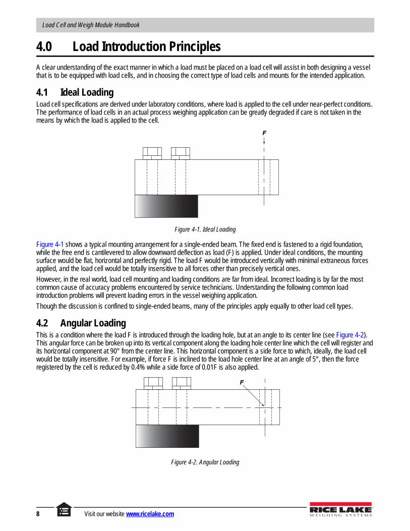
4.1 Ideal LoadingLoad cell specifications are derived under laboratory conditions, where load is applied to the cell under near-perfect conditions. The performance of load cells in an actual process weighing application can be greatly degraded if care is not taken in the means by which the load is applied to the cell.
F
Figure 4-1. Ideal Loading
Figure 4-1 shows a typical mounting arrangement for a single-ended beam. The fixed end is fastened to a rigid foundation, while the free end is cantilevered to allow downward deflection as load (F) is applied. Under ideal conditions, the mounting surface would be flat, horizontal and perfectly rigid. The load F would be introduced vertically with minimal extraneous forces applied, and the load cell would be totally insensitive to all forces other than precisely vertical ones.
However, in the real world, load cell mounting and loading conditions are far from ideal. Incorrect loading is by far the most common cause of accuracy problems encountered by service technicians. Understanding the following common load introduction problems will prevent loading errors in the vessel weighing application.
Though the discussion is confined to single-ended beams, many of the principles apply equally to other load cell types.
4.2 Angular LoadingThis is a condition where the load F is introduced through the loading hole, but at an angle to its center line (see Figure 4-2). This angular force can be broken up into its vertical component along the loading hole center line which the cell will register and its horizontal component at 90° from the center line. This horizontal component is a side force to which, ideally, the load cell would be totally insensitive. For example, if force F is inclined to the load hole center line at an angle of 5°, then the force registered by the cell is reduced by 0.4% while a side force of 0.01F is also applied.
F
Figure 4-2. Angular Loading
8 Visit our website www.ricelake.com

Introduction to Load Cells
If the direction of the force is constant, calibration will compensate for this and the scale will weigh accurately. However, if the angle changes as the force is applied, it will cause nonlinearity and if there is friction in the mechanical system, hysteresis will also be present. Angular loads can be caused by mounts that are out of level, a nonrigid foundation, thermal expansion/contraction, structure deflection under load, and the unavoidable deflection of the load cell itself.
4.3 Eccentric LoadingThis is a condition where the load F is applied vertically to the cell, but its line of action is shifted away from the vertical line through the loading hole (see Figure 4-3). This is not a detrimental condition if the force is applied consistently at the same point, since calibration will compensate for this effect. However, if the point of application moves horizontally as the scale is loaded, it will cause nonlinearity and possibly hysteresis. Eccentric loads may be caused by poorly designed mounting arrangements, thermal expansion/contraction of the scale and damaged parts.
F
Figure 4-3. Eccentric Loading
4.4 Side LoadingThis is a condition where the vertical load F (which is to be measured) is accompanied by a side force R applied at 90° to F (see Figure 4-4). This force can be constant, but more typically is a force that varies over time and hence affects the linearity and possibly the hysteresis of the scale. The ideal load cell would be totally insensitive to side loads. However, in practice these extraneous forces do affect the output of the cell and two seemingly identical cells can react differently to the same side load. A related condition is the end force, P, which is similar to a side force, except that it acts on the end face of the cell. Side forces are typically the result of thermal expansion/contraction, mounts which are not level, and vessel dynamics (caused by mixers, etc.).
F
R P
Figure 4-4. Side Loading
© Rice Lake Weighing Systems All Rights Reserved 9

Load Cell and Weigh Module Handbook
4.5 Twisting LoadsTypically, a side force does not act exactly at the neutral axis and hence produces a torque or twisting effect in addition to the side force. A load cell can be subjected to a torque (T) in a number of ways. Figure 4-5(a) illustrates a condition where the line of action of a side force is moved away from the neutral axis by a distance h resulting in a torque of Rh. Figure 4-5(b) illustrates a situation where the load is hung from the cell using a bolt. Any side force applied by this arrangement has a much larger twisting effect on the cell because of the increased distance h1 to the neutral axis.
R
R
h
(a) (b)
h1
T
T
Figure 4-5. Twisting Loads
Figure 4-6 illustrates a torque of magnitude Fy exerted as the result of the load F being applied at a distance y from the loading hole center line.
F
y
Figure 4-6. Twisting Loads
Mounts which are out of level as well as thermal expansion/contraction, structure deflection under load and dynamic side forces (caused by rotating mixers, etc.) all cause twisting of the load cell. Since these forces tend to vary in magnitude as a function of time, temperature and/or load, the effects are not predictable, and will degrade system accuracy.
10 Visit our website www.ricelake.com

Introduction to Load Cells
5.0 DC Circuit Theory
5.1 ElectronAn electron is a negatively charged particle that is a part of all atoms. Electrons found in orbits closer to the atom's center, or nucleus, are held into the atomic structure more closely than those electrons in the outermost orbit. Conductors such as gold, copper and silver have one electron in their outer orbit, also called the valence shell. These valence electrons can easily escape their atom and move randomly to another atom. These electrons are called free electrons. Free electrons bump into other valence electrons, causing more free electrons. Conductors have many free electrons randomly moving from atom to atom.
Insulators are opposite of conductors. Their valence shells contain many electrons which are tightly held to their atoms. Insulators have few free electrons and are very poor conductors of electricity.
5.2 Current and VoltageElectrical current is the orderly flow of electrons. When electrons flow past a given point at the rate of 6.24 x 10¹⁸ electrons per second, one ampere (amp) of current is present. The name given to the number 6.24 x 10¹⁸ is a coulomb. So we can say one ampere of current is equal to one coulomb passing a given point in one second. The symbol used for amperes is A.
In order to move electrons in a conductor to produce current flow, a force must be exerted on the conductor. In electrical circuits this force is a difference in electrical potential between two points and is called voltage. So, current is the actual electron flow and the voltage is the force that causes the electrons to flow. The symbol used in electronics for current is I, and is measured in amperes (A). The symbol for voltage is E.
5.3 ResistanceCurrent flowing through a conductor encounters opposition from the conductor. This opposition to current flow is called resistance. The symbol used to denote resistance is R. The unit of measure for resistance is called the ohm (Ω).
5.4 Direct Current CircuitsA German physicist named G.S. Ohm developed a definite relationship between voltage, current and resistance in a closed circuit. A circuit consists of a voltage source and a complete path for current flow. The path must start at one side of the voltage source and end at the other side. This gives the circuit a complete, uninterrupted path and also establishes a potential difference between ends of the path since one side of the source has a positive potential and the other side has a negative potential. Mr. Ohm stated, "Current is directly proportional to voltage and inversely proportional to resistance." This relationship is known as Ohm's Law.
As a formula, Ohm's Law looks like this:
Current (in amperes) =Voltage (in volts)
Resistance (in ohms)
Using the symbols for current, voltage and resistance, this relationship is shown as I = E/R. More commonly, Ohm's Law is referred to in the form E = IR, or voltage equals current times resistance.
To symbolize a direct current circuit we use the symbol to represent the battery which is the power source. The symbol for resistance is . The diagram of a simple direct current circuit is shown in Figure 5-1 on page 12.
© Rice Lake Weighing Systems All Rights Reserved 11

Load Cell and Weigh Module Handbook
Battery (E)
Resistor (R)
+
--
Notice there is a voltage source (battery), a conductor path and opposition to the current (resistance). The path is also closed to allow current flow through the circuit.
Figure 5-1. Direct Current Circuit
The resistance is the load or what is being acted upon by the current. It could be a light bulb, heating element or any other type of resistive electrical component, such as a load cell.
Let's take a closer look at Ohm's Law, I = E/R. Since voltage and current are directly proportional, increasing the battery voltage of the circuit will also increase the current flow. Also decreasing the resistance will increase current flow as current and resistance are indirectly proportional.
5.4.1 Series Resistive CircuitA series circuit contains a power source, one or more resistances and only one path for current flow. Let's look at a series circuit with two resistors.
ET = 10 V R1
R2
+
--
Figure 5-2. Series Resistive Circuit
Looking at the circuit, we find a 10 V power source. There are two resistors in the circuit and only one path for current to flow. The current in a series circuit is constant, no matter where the current is measured in the circuit, it will be the same.
The total resistance (RT) in the circuit is the sum of all resistances. (RT = R1 + R2 ...). The total resistance of our circuit is 400 Ω. Using Ohm's Law we can find the total current in the circuit: IT = ET / RT, IT = 10 V / 400 Ω = 0.025 amps (A) or 25 milliamps (mA). Since we know the total current, we know the current through R1 and R2 (IR1, IR2). Current is constant in a series circuit so IT = IR1 = IR2. The sum of the voltage drops in a series circuit are equal to the applied voltage. What is the voltage drop across R1? Using Ohm's Law the voltage drop across R1 (ER1) equals the current through R1 (IR1) times the resistance of R1.
In a formula it looks like this: ER1 = IR1R1
ER1 = 0.025 A x 100 Ω = 2.5 V
ER2 = 0.025 A x 300 Ω = 7.5 V
ET = ER1 + ER2
ET = 2.5 V + 7.5 V = 10 V
12 Visit our website www.ricelake.com

Introduction to Load Cells
Let's look at another example.
ET = 120 VRT
R2
R3 =
R1
Find: ER1
ER2
ER3
Figure 5-3. Series Resistive Circuit
The problem asks to find the voltage drops across each of the resistors. First, find the total circuit current, which also equals the current through each of the resistors. Using Ohm's Law:
IT= ET / RT
IT = 120 V / 6000 Ω
IT = 20 mA
We also know that: RT = R1 + R2 + R3
To find R3 we can say: R3 = RT - R1 - R2
R3 = 6 KΩ - 2 KΩ - 1 KΩ
R3 = 3 KΩ
Using Ohm's Law to find ER1, ER2 and ER3:
ER1 = IR1 x R1
= 0.020 A x 2000 Ω
= 40 V
ER2 = IR2 x R2
= 0.020 A x 1000 Ω
= 20 V
ER3 = IR3 x R3
= 0.020 A x 3000 Ω
= 60 V
© Rice Lake Weighing Systems All Rights Reserved 13

Load Cell and Weigh Module Handbook
5.4.2 Parallel Resistive CircuitA parallel circuit contains a power source and more than one path for current.
R1 = 100
IR1 = IR2 =
R2 = 200
ET = 10 V
Figure 5-4. Parallel Resistive Circuit
In a parallel circuit the total voltage (ET) is applied to all circuit branches. Because of this, it is said voltage in a parallel circuit is constant. The total circuit current is the sum of all branch currents.
Total resistance in a parallel circuit is found by calculating the reciprocal of the sum of the reciprocals for each resistance. This concept in a formula looks like this:
RT =1
1/R1 + 1/R2...
For our circuit:
RT =1
1/100 + 1/200
RT =1
0.015
RT = 66.67 Ω
Notice that the total resistance is lower than the lowest individual resistance. For two resistors in parallel, total resistance can also be computed by using a formula called "Product Over the Sum." It looks like this:
RT =R1 x R2R1 + R2
RT =100 x 200
100 + 200
RT =20000
300
RT = 66.67 Ω
If the parallel resistors are the same value, it can be divided by the total number of resistors. For example, if there are five (5), 100 ohm resistors in parallel the total resistance would be 100 Ω / 5 or 20 Ω.
In our example circuit we can find total current by using Ohm's Law:
IT =ERRT
IT =10 V
66.67 Ω
IT = 0.15 A or 150 mA
14 Visit our website www.ricelake.com

Introduction to Load Cells
Use Ohm's Law to find IR1 and IR2.
IR1 =ER1R1
=10 V
100 Ω
= 0.1 A or 100 mA
IR2 =ER2R2
=10 V
200 Ω
= 0.05 A or 50 mA
By adding IR1 and IR2 we find the total circuit current is 150 mA, just as we calculated with Ohm's Law.
Let's look at another example.
RT
R1 = 100K
IR1 = IR2 = 0.002 A
R2 =
Find: ET
R1
R3
IR1
R1 =
IR3 = 0.001 A
Figure 5-5. Parallel Resistive Circuit
Let's start by finding ET. We know that ET is the same as the voltage applied to each branch. Since we know R2 and IR2 we can use Ohm's Law to find ER2 which is the same as ET.
ER1 = R1 x IR1
= 100,000 Ω x 0.002 A
= 200 V
Since we know ET we can find R3.
R3 =ETIR3
= 200 V0.001 A
= 200 KΩ
© Rice Lake Weighing Systems All Rights Reserved 15

Load Cell and Weigh Module Handbook
We know ET and RT is given. Use Ohm's Law to figure out IT.
IT =ETIT
= 200 V28.57 KΩ
= 7 mA or 0.007 A
Since IT = IR1 + IR2 + IR3 we can figure out the current through branch resistor IR1.
IR1 = IT - IR3 - IR2
= 7 mA - 1 mA - 2 mA
= 4 mA or 0.004 A
Since we know ET and IR1 we can find R1 using Ohm's Law.
R1 =ETIR1
= 200 V0.004 A
= 50 KΩ
5.4.3 Series-Parallel CircuitA series-parallel circuit has at least two parallel branches in addition to at least one resistor through which total circuit current flows. The resistor through which all circuit current flows is called the series resistor.
Below is an example of a series-parallel circuit.
ET = 10 V
R2 = 100
Find: RT
IT
ER1
ER2
ER3
R1 = 50
R3 = 150
Figure 5-6. Series-Parallel Circuit
To find total circuit resistance, find the equivalent resistance (Req) of R2 and R3 in parallel.
Req = 11/R2 + 1/R3
= 11/100 + 1/150
= 60 Ω
16 Visit our website www.ricelake.com

Introduction to Load Cells
The equivalent series circuit is shown below.
ET = 10 V
Req = Equivalent Resistance
R1 = 50
Req = 60
Figure 5-7. Series-Parallel Circuit Equivalent
To find RT add the series resistances. RT = R1 + Req
RT = 50 Ω + 60 Ω
= 110 Ω
.
To find total current in the circuit use Ohm's Law.
IT =ETRT
= 10 V100 Ω
= 0.091 A or 91 mA
Since total circuit current flows through R1 we can say IT = IR1. Using Ohm's Law we can figure the voltage drop across R1.
ER1 = IR1R1
= 0.091 A x 50 Ω
= 4.55 V
© Rice Lake Weighing Systems All Rights Reserved 17

Load Cell and Weigh Module Handbook
Since R1 drops or uses 4.55 volts, that leaves 10 V - 4.45 V or 5.45 volts to be dropped across the parallel network of R2 and R3. Using Ohm's Law we can determine the current flow through R2 and R3. The total current in the circuit will divide proportionately between R2 and R3. In other words, the total current in the circuit will be the sum of the branch currents IR2 and IR3.
IR2 =ER2R2
= 5.45 V100 Ω
= 0.0545 A or 54.5 mA
IR3 =ER3R3
= 5.45 V150 Ω
= 0.0363 A or 36.3 mA
IT = IR2 + IR3
= 54.5 mA + 36.3 mA
= 90.8 mA
Rounding off the 90.8 mA to the nearest whole number, we get 91 mA just as we calculated earlier.
Remember that a series-parallel circuit has to have at least one component through which total circuit current passes. The following type of circuit is sometimes incorrectly referred to as a series-parallel circuit.
ET = 6 V
R2 = 4.5K
R1 = 1.5K
R4 = 10K
R3 = 2K
Figure 5-8. Parallel Circuit
Using our definition of series-parallel circuits, we can see that total circuit current does not flow through any of the components. This circuit is actually a parallel circuit.
To determine the current flow through R1 + R2 we need to add these resistances for a total branch resistance of 6 KΩ. Using Ohm's Law we can find the current through branch R1 + R2.
IR1+R2 =ER1 + ER2R1 + R2
= 6 V6,000 Ω
= 0.001 A or 1 mA
18 Visit our website www.ricelake.com

Introduction to Load Cells
To determine the current flow through R3 + R4 we add their resistances for a total of 12 KΩ. Use Ohm's Law to calculate total current.
IR3+R4 =ER3 + ER4R3 + R4
= 6 V12,000 Ω
= 0.0005 A or 0.5 mA or 500 µA
Total circuit current is the sum of the currents through both branches or IT = IR3 + R4 + IR1 + R2 or 1 mA + 0.5 mA = 1.5 mA.
To calculate total circuit resistance we can use Ohm's Law again.
RT =ETIT
= 6 V0.0015 A
= 4,000 Ω or 4 KΩ
We can also calculate total resistance by using the "reciprocal of the sum of the reciprocals" formula or the "product over the sum" formula. We know the R1 + R2 branch resistance is 6.0 KΩ and the R3 + R4 branch resistance is 12 KΩ.
RT =1
1 + 1R1 + R2 R3 + R4 OR
= 11/6,000 + 1/12,000
= 13/12,000
= 11/4,000
= 4,000 Ω or 4 KΩ
RT =(R1 + R2) x (R3 + R4)(R1 + R2) + (R3 + R4)
= (6,000) x (12,000)6,000 + 12,000
= 72,000,00018,000
= 4,000 Ω or 4 KΩ
If we want to know the voltage drop across each resistor we can also use Ohm's Law. Looking at R1 we know that the current through R1 equals the current through R2 and the branch made up of R1 + R2, because these two resistances are in series with each other. Using Ohm's Law we can multiply the resistance of R1 times the current through R1 (IR1) to find ER1 (voltage drop across R1).
ER1 = R1IR1
= 1,500 Ω x 0.001 A
= 1.5 V
Ohm's Law can also be used to find voltage drops throughout the rest of the circuit.
This circuit is the foundation for building a Wheatstone bridge circuit which is the circuit used in load cells. We will explore this circuit in the next section.
© Rice Lake Weighing Systems All Rights Reserved 19

Load Cell and Weigh Module Handbook
5.5 Conductor SizeA conductor or wire has a certain amount of resistance depending on its diameter. The larger the diameter, the lower the resistance. If we stretch the wire we have decreased its diameter, or cross-sectional area, thus increasing its resistance. The opposite is also true. If we compress the wire, its diameter is increased and its resistance is decreased. Since it takes a force to act upon the wire to compress or stretch it, the wire can be configured to measure force. This configuration of wire is called a strain gauge.
5.6 Strain GaugeA strain gauge consists of a very fine length of wire that is woven back and forth in a grid and laid on a piece of paper or plastic called its base. A common wire used is a copper-nickel alloy with a diameter of about one thousandth of an inch (0.001"). The wire is zig-zagged to form a grid so to increase the effective length of the wire that comes under the influence of the force applied to it. Leads are attached to the ends of the gauge. Strain gauges can be made very small, sometimes as small as 1/64". These gauges are cemented to a strong metal object, commonly referred to as the load receiving element, to make up a load cell. The gauges are configured into a circuit called a Wheatstone bridge.
Figure 5-9. Strain Gauge
5.7 Wheatstone BridgeThe type of resistive circuit used in load cells is a Wheatstone bridge.
ET = 10 V R1 = 350
R3 = 350
R2 = 350
R4 = 350
A
Note All resistors are equal.
A is a symbol for an ammeter, a device used to measure current flow and direction.
Figure 5-10. Balanced Wheatstone Bridge
When power is applied to this bridge the current flowing in the R1 / R3 branch is equal to the current flowing in the R2 / R4 branch. This is true because all resistors are equal. Since there is no voltage difference between points 1 and 2 there is no current flow through the ammeter. This bridge is in a balanced condition.
20 Visit our website www.ricelake.com

Introduction to Load Cells
Now let's increase the resistance of R1 and R4 to 350.5 ohms, and decrease the resistance of R2 and R3 to 349.5 ohms.
ET = 10V R1 = 350.5
R3 = 349.5
R2 = 349.5
R4 = 350.5
A
Figure 5-11. Unbalanced Wheatstone Bridge
Observe that the bridge becomes unbalanced. There is actually three paths for current flow in this circuit.
• Path 1 Negative battery terminal through R2 and R4 back to the positive battery terminal.• Path 2 Negative battery terminal through R1 and R3 back to the positive battery terminal.• Path 3 Negative battery terminal through R2, the ammeter, R3 and back to the positive battery terminal.
Notice this time there is current flow through the ammeter. This current flow is a result of a potential difference between points 1 and 2. The larger the potential difference the larger the current flow through the ammeter.
5.8 Load CellWe can take our strain gauge and Wheatstone bridge theories and use them to construct a load cell. We will use a column of steel and glue a strain gauge on each of the four sides of the column. As weight is placed on top of the column, the length of the column would decrease. The column also would become "fatter," or bulge out. Two strain gauges are placed opposite of each other to respond proportionately to the change in length.
Two other gauges are placed on opposite sides of the column and respond to the change in the column's bulge. Since one pair of strain gauges become shorter their wire diameters become larger and their resistance decreases. The other pair of strain gauges are positioned so their wires lengthen, thus decreasing their diameter and increasing their resistance. If we hung the same weight from the bottom of the column instead of compressing the column we would be placing tension on it. The column and strain gauges would act in the opposite direction but still stretch and compress the wires by the same amount. See Figure 5-12.
Load
Front & back gauges shorten,wire diameter increases.
Side gauges lengthen,wire diameter decreases.
Figure 5-12. Strain Gauge
© Rice Lake Weighing Systems All Rights Reserved 21

Load Cell and Weigh Module Handbook
We can wire our strain gauges into a Wheatstone bridge configuration. We can calibrate the ammeter to read in pounds instead of amps. In effect we actually have a scale. Of course this is a crude, very inaccurate scale. It is intended to show the basic load cell principle. Load cells are made in different shapes and configurations. The strain gauges are strategically placed for peak performance. See Figure 5-13.
- Output
+ Output
- Excitation
+ Excitation
Figure 5-13. Load Cell
22 Visit our website www.ricelake.com

Introduction to Load Cells
6.0 Load Cell Electrical Theory
6.1 WiringA load cell can have a cable with four or six wires. A six-wire load cell, besides having + and - signal and + and - excitation lines, also has + and - sense lines. These sense lines are connected to the sense connections of the indicator. These lines tell the indicator what the actual voltage is at the load cell. Sometimes there is a voltage drop between the indicator and load cell. The sense lines feed information back to the indicator. The indicator either adjusts its voltage to make up for the loss of voltage, or amplifies the return signal to compensate for the loss of power to the cell.
Load cell wires are color coded to help with proper connections. The load cell calibration data sheet for each load cell contains the color code information for that cell. Rice Lake Weighing Systems also provides a load cell wiring color guide on the back cover of the Load Cell Guide and a wire guide phone app at www.ricelake.com/wireapp.
6.2 Calibration DataMost load cells are furnished with a calibration data sheet or calibration certificate. See Section 7.0 on page 27 for an example of a calibration certificate. This sheet provides pertinent data about the load cell. The data sheet is matched to the load cell by model number, serial number and capacity. Other information found on a typical calibration data sheet is output expressed in mV/V, excitation voltage, non-linearity, hysteresis, zero balance, input resistance, output resistance, temperature effect on both the output and zero balance, insulation resistance and cable length. The wiring color code is also included on the calibration data sheet.
Figure 6-1 illustrates a calibration curve and shows how many of the important load cell terms above relate to each other.
Rated Output
Calibration Curve
Zero Balance
LOAD
B
OU
TP
UT
Non-Linearity
Combined Error
Hysteresis
Repeatability
Figure 6-1. Calibration Curve
© Rice Lake Weighing Systems All Rights Reserved 23

Load Cell and Weigh Module Handbook
6.3 OutputA load cell’s output is not only determined by the weight applied, but also by the strength of the excitation voltage, and its rated mV/V full scale output sensitivity. A typical full scale output for a load cell is 3 millivolts/volt (mV/V). This means that for each volt of excitation voltage applied at full scale there will be 3 millivolts of signal output. If we have 100 lb applied to a 100 lb load cell with 10 volts excitation applied, the load cell signal strength will be 30 mV. That is 10 V x 3 mV/V= 30 mV. Now let’s apply only 50 lb to the cell, keeping our excitation voltage at 10 volts. Since 50 lb is 50% or one half of full load, the cell signal strength would be 15 mV.
58 Ω
30 Ω 10 Ω
58 Ω
30 Ω 10 Ω
-In (-Exc)
+Out (+Sig)
+In (+Exc)
-Out (-Sig)
T2 350.5 ΩC1 349.5 Ω
T1 350.5 Ω
C2 349.5 Ω
Figure 6-2. Wheatstone Bridge
The Wheatstone bridge shown in Figure 6-2 is a simple diagram of a load cell. The resistors marked T1 and T2 represent strain gauges that are placed in tension when load is applied to the cell. The resistors marked C1 and C2 represent strain gauges which are placed in compression when load is applied.
The +In and -In leads are referred to as the +Excitation (+Exc) and -Excitation (-Exc) leads. The power is applied to the load cell from the weight indicator through these leads. The most common excitation voltages are 10 VDC, and 15 VDC depending on the indicator and load cells used. The +Out and -Out leads are referred to as the +Signal (+Sig) and -Signal (-Sig) leads. The signal obtained from the load cell is sent to the signal inputs of the weight indicator to be processed and represented as a weight value on the indicator’s digital display.
As weight is applied to the load cell, gauges C1 and C2 compress. The gauge wire becomes shorter and its diameter increases. This decreases the resistances of C1 and C2. Simultaneously, gauges T1 and T2 are stretched. This lengthens and decreases the diameter of T1 and T2, increasing their resistances. These changes in resistance cause more current to flow through C1 and C2 and less current to flow through T1 and T2. Now a potential difference is felt between the output or signal leads of the load cell.
Now trace the current flow through the load cell. Current is supplied by the indicator through the -In lead. Current flows from -In through C1 and through -Out to the indicator. From the indicator current flows through the +Out lead, through C2 and back to the indicator at +In. In order to have a complete circuit, we needed to get current from the -In side of the power source (Indicator) to the +In side and we accomplished that. Current also needs to pass through the indicator’s signal reading circuitry. We accomplished that as the current passed from the -Out lead through the indicator and back to the load cell through the +Out lead. Because of the high internal impedance (resistance) of the indicator, very little current flows between -Out and +Out.
24 Visit our website www.ricelake.com

Introduction to Load Cells
Since there is a potential difference between the -In and +In leads, there is still current flow from -In through T2 and C2 back to +In, and from -In through C1 and T1 back to +In. The majority of current flow in the circuit is through these parallel paths. Resistors are added in series with the input lines. These resistors compensate the load cell for temperature, correct zero and linearity.Let’s look at a load cell bridge circuit in mathematical terms to help in understanding the bridge circuit in both a balanced and unbalanced condition. Our Wheatstone bridge can either be drawn in a conventional diamond shape or as shown in Figure 6-3 on page 25. Either way, it is the same circuit.
ET = 10 V
R2 = 350
R1 = 350
R4 = 350
R3 = 350
V 12+Sig -Sig
+Exc
-Exc
Figure 6-3. Wheatstone Bridge
We have replaced the ammeter with a voltmeter which will represent the display on our weight indicator. Also, the leads connected to our indicator are designated +Sig and -Sig. These represent our positive and negative signal leads. A 10 volt battery represents our indicator’s power supply that provides the precise voltage to excite or power the load cell. The resistance values represent our four strain gauges which make up our load cell.
Since there is no load on our cell, all strain gauge resistances are the same. Using Ohm’s Law we can figure the voltage drops at points 1 and 2. Each branch contains 350 Ω + 350 Ω = 700 Ω of resistance. The current flow in the branch is the branch voltage divided by the branch resistance.
IR1 + R2= ER1 + R2 IR3 + R4= ER3 + R4
R1 + R2 R3 + R4
= 10 V = 10 V
700 Ω 700 Ω
= 14.3 mA or 0.0143 A = 14.3 mA or 0.0143 A
To figure the voltage at point 1 we can use Ohm’s Law.
ER3 = IR3R3
= 0.0143 A x 350 Ω
= 5 V
Since all resistances are equal, the voltage at point 2 is also 5 V. There is no voltage difference between points 1 and 2 thus a zero reading is displayed on our indicator.
© Rice Lake Weighing Systems All Rights Reserved 25

Load Cell and Weigh Module Handbook
Now let's place a force on our load cell. Our force caused R1 and R4 to go into tension, which increased their resistances. R2 and R3 went into compression, which decreased their resistances. These changes are depicted in the following diagram.
ET = 10 V
R2 = 349.5
R1 = 350.5
R4 = 350.5
R3 = 349.5
V 12
Figure 6-4. Wheatstone Bridge
Notice that the individual branch resistances still total 700 Ω, so there is still 0.0143 A of current in each branch of our circuit.
However, there is a potential difference between points 1 and 2, thus a reading is displayed on our indicator. Let's calculate the potential difference.
To find the voltage at point 1 we will calculate the voltage drop across R3. We know the current through R3 is 0.0143 A.
ER3 = IR3R3
= 0.0143 A x 349.5 Ω
= 4.9979 V
To find the voltage at point 2 we will calculate the voltage drop across R1. Again, we know the current through R1 is 0.0143 A.
ER1 = IR1R1
= 0.0143 A x 350.5 Ω
= 5.0122 V
To find the potential difference between points 1 and 2, subtract ER3 from ER1 and find the difference to be 0.0143 V or 14.3 mV.
We see that our bridge has become unbalanced and the potential difference across the bridge is 14.3 mV. The indicator is calibrated so a certain millivolt reading would correspond to a certain weight measurement. As we previously stated the indicator draws current. But its internal resistance is so high that the current it draws is negligible and has no affect on load cell operation.
26 Visit our website www.ricelake.com

Introduction to Load Cells
7.0 Rice Lake Weighing Systems Calibration Certificate
1. Model No. 50210-252. Serial No. 376473. Capacity 25 lb4. Output 3.0678 mV/V5. Excitation 10 Volts6. Non-Linearity < 0.010 % FSO7. Hysteresis < 0.010 % FSO8. Zero Balance -0.0230 mV/V9. Input Resistance 375 Ohms Nominal
10. Output Resistance 350 Ohms11. Temperature Effect
Output < 0.0005 % / FZero < 0.0010 % / F
Insulation Resistance 5000 Mega Ohms at 50 VDCCable Length 20 ft
NTEP Certificate No. ****Minimum Dead Load (lb) ****Class ****V min ****n Maximum ****Load Cell Usage ****Safe Load Limit (lb) ****
Table 7-1. Wiring Color Code
Wiring
Red + Input
Green + Output
White - Output
Black - Input
© Rice Lake Weighing Systems All Rights Reserved 27

Load Cell and Weigh Module Handbook
28 Visit our website www.ricelake.com

Weigh Modules
Weigh Modules
8.0 Weigh Modules: Single-Ended Beam . . . . . . . . . . . . . . . . . . . . . . . . . . . . . . . . . . . . . . . 308.1 Introduction . . . . . . . . . . . . . . . . . . . . . . . . . . . . . . . . . . . . . . . . . . . . . . . . . . . . . . . . . . . . . . . . . . . 30
8.1.1 General Mounting Principles. . . . . . . . . . . . . . . . . . . . . . . . . . . . . . . . . . . . . . . . . . . . . . 308.1.2 Single-Ended Beam Orientation . . . . . . . . . . . . . . . . . . . . . . . . . . . . . . . . . . . . . . . . . . . 30
8.2 SURVIVOR RL1700 Series Weigh Modules . . . . . . . . . . . . . . . . . . . . . . . . . . . . . . . . . . . . . . . . 318.3 RL50210 TA Weigh Modules . . . . . . . . . . . . . . . . . . . . . . . . . . . . . . . . . . . . . . . . . . . . . . . . . . . . . 328.4 RL1800 / SURVIVOR RL1855 HE Weigh Modules. . . . . . . . . . . . . . . . . . . . . . . . . . . . . . . . . . . . . 338.5 RL1900 Weigh Modules . . . . . . . . . . . . . . . . . . . . . . . . . . . . . . . . . . . . . . . . . . . . . . . . . . . . . . . . . 348.6 Paramounts HS and Paramounts EP . . . . . . . . . . . . . . . . . . . . . . . . . . . . . . . . . . . . . . . . . . . . . . 35
9.0 Weigh Modules: Double-Ended Beam. . . . . . . . . . . . . . . . . . . . . . . . . . . . . . . . . . . . . . . 379.1 Introduction . . . . . . . . . . . . . . . . . . . . . . . . . . . . . . . . . . . . . . . . . . . . . . . . . . . . . . . . . . . . . . . . . . . 37
9.1.1 General Mounting Principles. . . . . . . . . . . . . . . . . . . . . . . . . . . . . . . . . . . . . . . . . . . . . . 379.1.2 Double-Ended Beam Orientation . . . . . . . . . . . . . . . . . . . . . . . . . . . . . . . . . . . . . . . . . . 37
9.2 RL1600 Weigh Modules . . . . . . . . . . . . . . . . . . . . . . . . . . . . . . . . . . . . . . . . . . . . . . . . . . . . . . . . . 389.3 SURVIVOR RL2100 HE Weigh Modules . . . . . . . . . . . . . . . . . . . . . . . . . . . . . . . . . . . . . . . . . . . . 399.4 EZ Mount 1 Weigh Modules . . . . . . . . . . . . . . . . . . . . . . . . . . . . . . . . . . . . . . . . . . . . . . . . . . . . . . 409.5 Translink™ Truck Scale Weigh Modules . . . . . . . . . . . . . . . . . . . . . . . . . . . . . . . . . . . . . . . . . . . . 419.6 MVS Truck Scale Modules . . . . . . . . . . . . . . . . . . . . . . . . . . . . . . . . . . . . . . . . . . . . . . . . . . . . . . . 42
10.0 Weigh Modules: Compression Canisters . . . . . . . . . . . . . . . . . . . . . . . . . . . . . . . . . . . . 4310.1 Introduction . . . . . . . . . . . . . . . . . . . . . . . . . . . . . . . . . . . . . . . . . . . . . . . . . . . . . . . . . . . . . . . . . . . 43
10.1.1 General Mounting Principles. . . . . . . . . . . . . . . . . . . . . . . . . . . . . . . . . . . . . . . . . . . . . . 4310.2 RLC Weigh Modules . . . . . . . . . . . . . . . . . . . . . . . . . . . . . . . . . . . . . . . . . . . . . . . . . . . . . . . . . . . . 44
11.0 Weigh Modules: Tension Mounting (S-Beam) . . . . . . . . . . . . . . . . . . . . . . . . . . . . . . . . 4511.1 Introduction . . . . . . . . . . . . . . . . . . . . . . . . . . . . . . . . . . . . . . . . . . . . . . . . . . . . . . . . . . . . . . . . . . . 45
11.1.1 General Mounting Principles. . . . . . . . . . . . . . . . . . . . . . . . . . . . . . . . . . . . . . . . . . . . . . 4511.2 ITCM Mounts. . . . . . . . . . . . . . . . . . . . . . . . . . . . . . . . . . . . . . . . . . . . . . . . . . . . . . . . . . . . . . . . . . 45
© Rice Lake Weighing Systems All Rights Reserved 29

Load Cell and Weigh Module Handbook
8.0 Weigh Modules: Single-Ended BeamRice Lake Weighing Systems offers a wide variety of weigh module styles, including the industry’s only waterproof-guaranteed modules. This section includes only some of the weigh modules offered by Rice Lake Weighing Systems, along with information on the design, construction, features and applications of these weigh modules. For a complete list of the weigh modules offered by Rice Lake Weighing Systems and any additional specifications, visit our website at www.ricelake.com/lcwm.
Please refer to the Load Cell Guide for the load cell options of all the Rice Lake Weighing Systems’ weigh modules.
8.1 IntroductionSingle-ended beam load cells offer many advantages when used in well-designed weigh modules. Modules using single-ended beam load cells have a low profile and are generally self-checking. Load cell replacement is possible in most single-ended beam mount systems by raising the vessel only enough to remove pressure from the cell.
Figure 8-1. Single-Ended Beam
8.1.1 General Mounting Principles• The mounting surface should be flat and level.• The mounting bolts should be torqued to specified values.• The mounting block should be thick enough to provide adequate threads for the mounting screws.• The corner of the mounting surface (where the cell cantilevers out) must be hardened to prevent peening.• The mounting bolts should be at least grade five to prevent stretching or the possibility of breaking.• The load should be applied vertically through the center line of the load hole (the load may be applied from above, as
illustrated in Figure 8-1, or may be hung from below).• The load introduction must provide flexibility to avoid the transmission of extraneous forces and to tolerate the
unavoidable deflection of the load cell itself.
8.1.2 Single-Ended Beam OrientationFigure 8-2 illustrates four different vessels and recommended mounting configurations for single-ended beam weigh modules. The vessels below, to the left, illustrate a vertical cylindrical vessel. Note that the longitudinal axis through each load cell points towards the center of the vessel.
This principle could also be used for the vessels to the right, if it were convenient to mount the cells in each corner with the longitudinal axis pointing toward the center. However, it may be more convenient, and is acceptable, to mount the cells as illustrated. As these cells are relatively immune to extraneous forces applied along the longitudinal axis of the cell, it should point in the direction of any prevalent side force (for example, on a roller conveyor, the load cells should point in the direction of travel).
Figure 8-2. Single-Ended Beam Orientation
30 Visit our website www.ricelake.com

Weigh Modules
8.2 SURVIVOR® RL1700 Series Weigh ModulesThese light- to medium-capacity modules use single-ended beam load cells and offer precision-machined, weld-less construction to maximize washdown cleaning effectiveness. This design, coupled with integral jacking/shipping bolts, eases installation and minimizes maintenance costs. OIML C3-certified load cells in capacities from 5-5,000 kg (11-11,023 lb) provide accurate, consistent weighments. The unique design of the RL1700 HE weigh module isolates the load cell from side loads and overloads, minimizing load cell mechanical damage and eliminating the need for extraneous hardware. The RL1700 HE weigh module offers a guaranteed waterproof rating to ensure reliable performance in moisture-laden environments.
Allowable Movement Figure 8-3 illustrates the RL1700 HE module’s capability to handle movement. The load may be checked in one of two directions. This allows positioning in one of two orientations for proper checking.
Figure 8-3. SURVIVOR RL1700 HE
Construction and Features• All stainless steel construction.• Hermetically sealed, stainless steel load cells, IP66/68, guaranteed waterproof.• OIML certified load cells from 5-5,000 kg (11-11,023 lb).• Bolt-in-place design; module bolts directly to tank leg without requiring additional load buttons or mounting plates.• Self-checking with lift-off/tip-over protection and jacking/shipping bolts.• Load cell is isolated from overload in all directions.• Weldless construction retains less residue and allows fast, thorough cleaning.• NTEP certified load cells are available upon request. Please visit our website at www.ricelake.com/lcwm for
more information.
Typical ApplicationsA typical application for the SURVIVOR RL1700 HE is multi-ingredient micro-batching as shown in Figure 8-4. Additional applications include meat and poultry processing, chemical batching/blending and dye/ink blending.
Figure 8-4. SURVIVOR RL1700 HE in Micro-Ingredient Batching
© Rice Lake Weighing Systems All Rights Reserved 31

Load Cell and Weigh Module Handbook
8.3 RL50210 TA Weigh ModulesThese low-capacity modules use single-ended beam load cells and provide a cost-effective alternative for low-range weighing needs with capacities from 50-2,500 lb (23-1,134 kg). A variety of features makes this module easy to install and an exceptional choice for various indoor weighing applications where checking requirements are low. Environmentally protected load cells, neoprene isolation/compression mounts and other Rice Lake components are the key to this module’s outstanding performance. The direct connection of the vessel to the flexible neoprene pad also acts to cushion shock loads.
Allowable MovementFigure 8-5 illustrates the RL50210 TA module’s capability to handle movement. The arrows indicate the various means by which the load introduction plate can move relative to the cell to minimize the transfer of extraneous forces.
Figure 8-5. RL50210 TA
Construction and Features• Large base plate and spacer washer, the load cell is attached or bolted directly to the base plate.• Environmentally protected load cells.• Load introduction through a steel plate bonded to a neoprene pad accommodates vessel movement in all directions.• Neoprene isolation/compression mounts allow for minor misalignment, thermal expansion and shock absorption.• This module is available in capacities from 50-2,500 lb (23-1,134 kg) in mild steel and stainless steel.• Capacities 500-2,500 lb (227-1,134 kg) incorporate an overload stop under the free end of the cell for durability.• Some capacities are NTEP certified. Please visit our website at www.ricelake.com/lcwm for more information.
Typical ApplicationsThese modules should be attached so their longitudinal axis aligns with the direction of greatest expected movement of the vessel or conveyor. On a roller conveyor, this would normally be along the line of conveyor travel. See Figure 8-6. Typical applications include conveyor/In-motion weighing, small tanks/hoppers and small platform scales where minor shock loading may be a problem.
Figure 8-6. RL50210 TA on Conveyor
32 Visit our website www.ricelake.com

Weigh Modules
8.4 RL1800 / SURVIVOR RL1855 HE Weigh ModulesThese weigh modules use single-ended beam load cells in center-pivoted modules with capacities up to 10,000 lb (4,536 kg) per module. While these are compression-style modules, the cell is actually mounted in tension since the load is introduced through a center loading bolt in a hanging trunnion suspended beneath the load cell. The trunnion can pivot in all directions on a set of spherical washers, allowing the top plate (attached to the vessel) to rock without twisting the load cell. This arrangement makes the modules self-centering, and able to accommodate movement in all directions. This module is self-checking and provides lift-off protection.
RL1800 and RL1855 HE modules allow the installer to adjust overall height easily with a center loading bolt that is attached to the hanging trunnion. This adjustment feature speeds the process of equalizing the load between all modules. These modules allow load cell removal and replacement without raising the tank – an important consideration in some installations.
Allowable MovementFigure 8-7 illustrates the RL1800 and RL1855 HE modules with arrows indication allowable movement.
Figure 8-7. RL1800 and RL1855 HE Modules on Horizontal Cylindrical Tank
Construction and Features• A base plate and spacer support the load cell.• A trunnion block is suspended below the free end of the cell and is attached to the cell using a bolt in tension which is
screwed into a threaded load hole. A spherical washer set is placed between the bolt head and block.• A chair arrangement is attached to the trunnion block through pivot screws, and the load is applied to the top plate of this
chair. This arrangement allows the chair to move in the directions indicated in Figure 8-7.• Self-checking design with lift-off/tip-over protection and lateral restraint.• The module provides height adjustment.• Accommodates a broad range of alloy steel, stainless steel and hermetically sealed stainless steel load cells.• RL1800 module is available in capacities from 250-10,000 lb (113-4,536 kg) in both mild steel and stainless steel, while
the RL1855 HE module is available in capacities from 1,000-10,000 lb (454-4,536 kg) in stainless steel.• RL1855 HE module has a PTFE-jacketed cable and integral conduit adapter to heighten chemical and moisture resistance.• Some capacities are NTEP certified. Please visit our website at www.ricelake.com/lcwm for more information.
Typical ApplicationsTypical applications for the RL1800 are conveyors and medium-capacity tanks and hoppers. Applications for the RL1855 HE include chemical batching/blending, fertilizer blending and medium-capacity tanks and hoppers as well.
LoadingBolt
Figure 8-8. RL1800 and RL1855 HE Modules on a Horizontal Cylindrical Tank
© Rice Lake Weighing Systems All Rights Reserved 33

Load Cell and Weigh Module Handbook
8.5 RL1900 Weigh ModulesThe RL1900 weigh module is similar in design to the RL1800, but accommodates slightly more lateral movement than the RL1800. This weigh module is suited for tank, hopper and bin weighing operations with medium-range capacities. Each module combines multi-directional movement and self-checking capabilities.
Allowable MovementFigure 8-9 illustrates the RL1900 modules with arrows indication allowable movement.
Figure 8-9. RL1900 Modules
Construction and Features• A base plate and spacer support the load cell.• A trunnion block is suspended below the free end of the load cell. It is attached to the load cell using a bolt which passes
through the clearance load hole and is retained by a nut at the top of the cell. Two spherical washer sets are used; one sits between the bolt head and trunnion block, the other sits between the nut and the top of the load cell (which is counterbored to accept the washer set).
• A chair arrangement is attached to the trunnion block through pivot screws; the load is applied to the top plate of this chair. This arrangement allows the chair to move in the directions indicated in Figure 8-9.
• This module allows slightly greater lateral movement than the RL1800 by virtue of the fact that the suspension bolt passes through a clearance load hole in the cell and has spherical washer sets at the top and bottom.
• Self-checking design with lift-off/tip-over protection and lateral restraint.• The module provides height adjustment.• Available in capacities from 1,000-10,000 lb (454-4,536 kg) in stainless steel.• This module can accommodate both environmentally protected and hermetically sealed load cells.• NTEP certified load cells. Please visit our website at www.ricelake.com/lcwm for more information.
Typical ApplicationsTypical applications for the RL1900 are medium-capacity tanks, bins and hoppers, as well as washdown or corrosive applications.
Figure 8-10. RL1900 Modules on Hopper Scale
34 Visit our website www.ricelake.com

Weigh Modules
8.6 Paramounts® HS and Paramounts EPThe versatile Paramounts vessel weighing system consists of three different weigh modules, which together make a complete system of fixed and sliding modules with single-ended load cells. This unique system allows a vessel to expand freely on sliding modules, yet the system is self-checking. All models are available in capacities up to 22,500 lb (10,206 kg).
Allowable Movementa. Fixed-Pin Module – With the fixed-pin module, the load is transferred from the top plate to the load cell via a load pin which enters a counterbore in the top plate and load cell. The pin acts as a pivot point and only allows the top plate to rotate while fixing the corner of the vessel.
b. Free-Sliding Module – With the free-sliding module, the load pin has a flat top surface on which the top plate is free to slide in all directions. To minimize friction, the top surface of the pin is PTFE-coated and slides on a smooth stainless steel slider plate. The cleanliness of these two surfaces is assured by a neoprene suction seal.
c. Side-Stop Module – The side-stop module uses the same PTFE-coated pin and stainless steel slider plate, but in addition it has side bumpers. These bumpers check the top plate movement laterally. The top plate is checked to move only in the direction of the longitudinal axis of the load cell.
A three-cell system uses one of each style of module; all additional modules are free-sliding.
a b c
Figure 8-11. The Three Module Designs of the Paramounts System Include the (a) Fixed-Pin Module, (b) Free-Sliding Module, and (c) Side-Stop Module
Construction and Features• No Torsional Effects: All SB4, SB10 and SB5 load cells incorporate a blind hole for load introduction. The load is
introduced via a convex loading pin. The convex surface allows the module’s top plate to rock without twisting the cell. The load pin is centered in the load hole by a pliable polymer “O” ring. The bottom of the blind hole is located on the neutral axis of the Flintec sensing section. Therefore, torsional effects are virtually eliminated.
• Jacking Screw and Lift-Off Protection: Each module consists of a base plate to which the load cell is attached and a top plate through which the load is introduced. A safety check screw is rigidly fixed to the top plate and passes through a large clearance hole in the washer plate attached to the base plate. This screw prevents lift-off and also may be used to jack up the empty vessel for load cell replacement.
• Allows Movement: There are three different styles of modules resulting from differences in the top plate and loading pin design. Each serves as part of a complete system that allows free movement of the attached vessel.
• Matched Outputs: The SB4, SB10 and SB5 load cells are matched output, stainless steel load cells. All Paramounts load cell kits use SB, SB10 and SB5 load cells with outputs matched to ±0.07%. This eliminates corner trimming at initial installation or recalibration when a load cell is replaced.
• Withstands Hostile Environments: Paramounts HS are available in mild steel or stainless steel with hermetically sealed stainless steel load cells. Paramounts EP models come standard with stainless steel, environmentally protected load cells.
• Available in capacities up to 22,250 lb (10,206 kg) in either mild steel or stainless steel.• Some capacities are NTEP certified. Please visit our website at www.ricelake.com/lcwm for more information.
© Rice Lake Weighing Systems All Rights Reserved 35

Load Cell and Weigh Module Handbook
Typical ApplicationsA three-module system would use one of each module. Scales requiring more than three modules use additional free-sliding modules. Figure 8-12 is a typical example of a six-module system. The fixed pin module fixes the vessel in the corner, allowing it to rotate about the loading pin only. The vessel will expand outward from this corner. The side-stop module placed at the opposite end keeps the vessel in check but does not restrict the expansion. The use of four free-sliding modules ensures that the vessel’s expansion/contraction is unrestricted in either direction.
FREE
FREE
SIDE FIXED
FREE FREE
Figure 8-12. Paramounts Mounting System on Cylindrical Tank
Figure 8-13. Paramounts on Suspended Hopper
36 Visit our website www.ricelake.com

Weigh Modules
9.0 Weigh Modules: Double-Ended Beam
9.1 IntroductionDouble-ended shear beams are medium- and high-capacity workhorses that are rugged, stable, and able to handle side loads well. The modules come in two varieties, an end-supported cells loaded in the center and a center-supported cells loaded at the ends. The end-loaded cell is used in the Translink hanging-link truck scale module described later in this section. The more common center-loaded version described below is used in the RL1600, RL2100 HE, EZ Mount 1, and MVS mounting systems.
Figure 9-1 shows some important guidelines for applying load to a center-loaded, double-ended shear beam and for orienting a module using this type of load cell.
Figure 9-1. Double-Ended Beam
9.1.1 General Mounting Principles• The load cell should be horizontal in both directions.• The load should be applied vertically through the cell’s center.• The load should be introduced without producing a twisting effect around the center.• The load must not move along the cell.
9.1.2 Double-Ended Beam OrientationIn Figure 9-2, we illustrate the best mounting position of double-ended beams for several vessel shapes, where a line from the center of the vessel is at right angles to the longitudinal axis through the load cell. The mounts for these cells allow the least restricted vessel movement. This is particularly important when significant thermal expansion/contraction is expected.
Some double-ended beam modules should be oriented with the load cell’s longitudinal axis in line with the expected movement. On a truck scale, that will normally be in the direction of truck travel.
Figure 9-2. Double-Ended Beam Orientation
© Rice Lake Weighing Systems All Rights Reserved 37

Load Cell and Weigh Module Handbook
9.2 RL1600 Weigh ModulesThese assemblies are suitable for medium- to heavy-capacity applications because of the inherent strength and stability of the double-ended center-loaded cell which is supported at both ends on pins. The modules are self-checking in all directions while allowing some freedom for the vessel to expand/contract in a single direction by sliding on the mounting pins. The modules also offer lift-off protection to prevent the tank from accidental tipping.
The RL1600 module is a rugged and economical module for use where minimal expansion/contraction movement is expected. Precise alignment is critical with these modules, as there is little room for misalignment with the clamping yoke that holds the load plate to the load cell. Load cell replacement requires raising the vessel only an inch to remove the cell.
The RL1600 series modules are available in either fabricated mild steel or cast iron, and in fabricated stainless steel where extra corrosion protection is required.
Allowable MovementThis module allows limited movement in a direction perpendicular to the longitudinal axis of the load cell.
Figure 9-3. RL1600 Weigh Module
Construction and Features• A rigid base plate with four cross-drilled uprights to support the pins holding the load cell.• A chair clamps around the load cell’s center. This arrangement allows the cell freedom to slide laterally a short distance
on the pins.• The module is self-checking in all directions.• Available in mild steel and stainless steel construction in capacities from 1,000-75,000 lb (454-34,020 kg), and in cast
iron from 1,000-25,000 lb (454-11,340 kg).
Typical ApplicationsTypical applications for the RL1600 are medium- to heavy-capacity tanks, bins and hoppers, as well as bulk material management.
Figure 9-4. RL1600 Weigh Modules on Low-Profile Tank
38 Visit our website www.ricelake.com

Weigh Modules
9.3 SURVIVOR RL2100 HE Weigh ModulesThese medium- to heavy-capacity modules are available in two sizes in capacities ranging from 20,000-100,000 lb (9,072-45,359 kg). The SURVIVOR RL2100 HE uses a double-ended shear beam load cell and is ideally suited for tanks, hoppers, and reactors that are subject to harsh, hostile environments. This module provides superior corrosion, moisture ingress, and mechanical protection. In the majority of applications, the assemblies are self-checking and held captive with no need for check or stay rods. The load cells are each waterproof guaranteed and NTEP certified by utilizing the RL75060S stainless steel load cell.
Allowable MovementFigure 9-5 illustrates the RL2100 HE module’s capability to handle movement.
Figure 9-5. SURVIVOR RL2100 HE
Construction and Features• Welded seal, stainless steel load cells, IP67, guaranteed waterproof.• Bolt-in-place design, module bolts directly to tank leg without requiring additional load buttons or mounting plates.• Tolerates eccentric loads and side loads of up to 100% of capacity.• PTFE jacketed cable is standard for maximum chemical resistance.
• All stainless steel construction.• Self-checking design with lift-off/tip-over protection.• NTEP certified. Please visit our website at www.ricelake.com/lcwm for more information.
Typical ApplicationsTypical applications for the SURVIVOR RL2100 HE include heavy-capacity tanks, blenders, reactors, and bulk inventory management, as well as petroleum refining process control and chemical blending/batching.
Figure 9-6. SURVIVOR RL2100 HE in Heavy-Capacity Application
© Rice Lake Weighing Systems All Rights Reserved 39
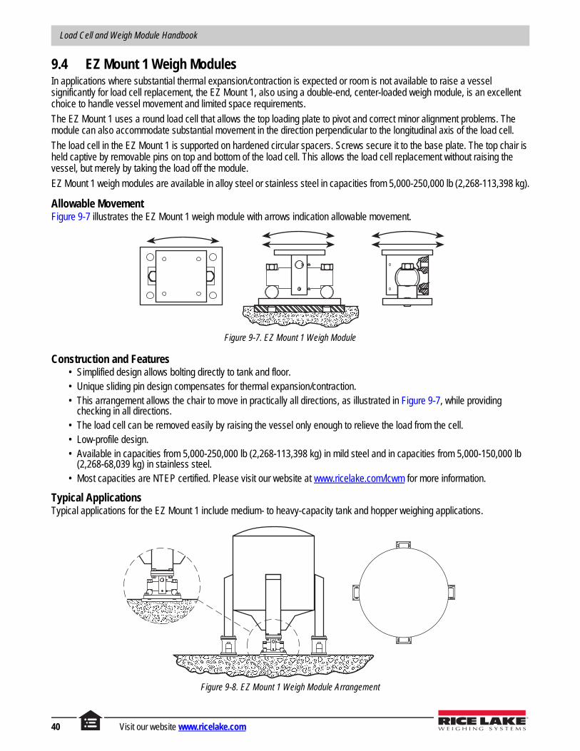
Load Cell and Weigh Module Handbook
9.4 EZ Mount 1 Weigh ModulesIn applications where substantial thermal expansion/contraction is expected or room is not available to raise a vessel significantly for load cell replacement, the EZ Mount 1, also using a double-end, center-loaded weigh module, is an excellent choice to handle vessel movement and limited space requirements.
The EZ Mount 1 uses a round load cell that allows the top loading plate to pivot and correct minor alignment problems. The module can also accommodate substantial movement in the direction perpendicular to the longitudinal axis of the load cell.
The load cell in the EZ Mount 1 is supported on hardened circular spacers. Screws secure it to the base plate. The top chair is held captive by removable pins on top and bottom of the load cell. This allows the load cell replacement without raising the vessel, but merely by taking the load off the module.
EZ Mount 1 weigh modules are available in alloy steel or stainless steel in capacities from 5,000-250,000 lb (2,268-113,398 kg).
Allowable MovementFigure 9-7 illustrates the EZ Mount 1 weigh module with arrows indication allowable movement.
Figure 9-7. EZ Mount 1 Weigh Module
Construction and Features• Simplified design allows bolting directly to tank and floor.• Unique sliding pin design compensates for thermal expansion/contraction.• This arrangement allows the chair to move in practically all directions, as illustrated in Figure 9-7, while providing
checking in all directions.• The load cell can be removed easily by raising the vessel only enough to relieve the load from the cell.• Low-profile design.• Available in capacities from 5,000-250,000 lb (2,268-113,398 kg) in mild steel and in capacities from 5,000-150,000 lb
(2,268-68,039 kg) in stainless steel. • Most capacities are NTEP certified. Please visit our website at www.ricelake.com/lcwm for more information.
Typical ApplicationsTypical applications for the EZ Mount 1 include medium- to heavy-capacity tank and hopper weighing applications.
Figure 9-8. EZ Mount 1 Weigh Module Arrangement
40 Visit our website www.ricelake.com

Weigh Modules
9.5 Translink™ Truck Scale Weigh ModulesSelf-centering mounting assemblies like the Translink are classified as compression-type mounts, yet actually apply load to their cells in a tension manner through a hanging pendulum mechanism below the load cell. The pendulum action gives them their unique self-centering ability.
The modules are commonly used to support a free-floating platform like a truck scale. The platform’s horizontal float is limited by bumper pads on all sides. The deck will always return to a central position after lateral movement and not remain in contact with the bumper pads.
Unlike the other double-ended beams described so far, the Translink mounting assembly uses an end-loaded shear beam that is supported by a concave or convex insert in the center that allows the cell to pivot.
Allowable MovementFigure 9-9 illustrates the Translink weigh module with arrows indication allowable movement.
Figure 9-9. Translink Weigh Module
Construction and Features• A bridge is welded to a base plate. The bridge can accommodate a hardened convex or concave insert on which the
load cell sits. Two roll pins prevent the cell from sliding sideways.• A forged link hangs from each end of the load cell, supporting a heat-treated load bar which passes under the bridge.
The load bar has circular grooves (corresponding to the loading grooves in the load cell) in which the links sit, and the top chair sits on each end of the load bar.
• Free movement in all directions in the horizontal plane with virtually no friction.• Completely self-centering, this module has a pendulous action which returns the deck to its original position after it has
been disturbed longitudinally or laterally.• This module is ideally suited for vehicle scales or high-capacity vessel scales.• This module requires the scale to be checked in the horizontal plane. Stay rods may be used or, because of the self-
centering action, bumper bolts are also sufficient. It does not provide lift-off protection which must be provided externally if required on a vessel scale.
• The Translink module is available in mild steel in capacities from 25,000-100,000 lb (11,340-45,359 kg).
Typical ApplicationsTypical applications for the Translink weigh module includes truck scale mounts and heavy-capacity horizontal tanks.
Figure 9-10. Translink Truck Scale Arrangement
© Rice Lake Weighing Systems All Rights Reserved 41

Load Cell and Weigh Module Handbook
9.6 MVS Truck Scale ModulesThe MVS load cell module is used primarily for truck scales, and in certain vessel-weighing applications. The modules are constructed of cast iron and are available in load cell capacities from 10,000-75,000 lb (4,536-34,019 kg). The center-link design provides freedom of movement in the longitudinal direction while also self-centering, making this module ideal for vehicle scales.
Unlike the double-ended beams used for the RL1600 or EZ Mount 1, the MVS module should be mounted with the greatest expected movement aligned with the longitudinal axis of the load cell. In a truck scale, this is normally in the direction of truck travel.
Allowable MovementFigure 9-11 illustrates the MVS weigh module with arrows indication allowable movement.
Figure 9-11. MVS Weigh Module
Construction and Features• The load cell ends are screwed to a rigid U-shaped base plate.• A link sits over the center of the cell which has a radiused groove at the center. The bottom of this link has two saddle
blocks which project outwards. The top girder chair assembly sits on these ears.• The module is free to move.• Because the load is suspended by a link, the scale is free to rock back and forth along the longitudinal axis of the load
cell. Because of the pendulous action of the link, the scale will return to its original position after being displaced along the longitudinal axis of the cell.
• When a number of modules are fastened to a deck, the modules are restrained from rocking laterally.• A scale using this module must be checked along the longitudinal axis of the load cell to prevent over-travel. Stay rods or
bumper bolts may be used.• The module does not provide lift-off protection which, if required in a vessel weighing application, must be provided
externally.
Typical ApplicationsTypical applications for the MVS weigh module includes truck/track scale conversion and heavy-capacity horizontal tanks.
Figure 9-12. MVS Truck Scale Arrangement
42 Visit our website www.ricelake.com

Weigh Modules
10.0 Weigh Modules: Compression Canisters
10.1 IntroductionWhen mounts are needed in capacities over 100,000 lb (45,359 kg), canister load cell mounts are one of the choices available. These cells are good in severe conditions and have provided proven performance for decades in truck, railroad, and heavy-capacity tank applications. Available in capacities to 500,000 lb (226,796 kg) per mount assembly, most canister mounting assemblies require more components than mounts using beam load cells, especially if the mounts are designed to accommodate expansion.
The load is transferred to the cell through a hardened, convex load button which mates with a hardened flat loading plate. The rounded load button and flat plate tend to promote point loading, minimizing extraneous forces.
10.1.1 General Mounting Principles• A compression canister should be mounted on a flat plate of sufficient thickness to prevent deflection. The foundation
must be rigid.• The load should be introduced through a spherically radiused load button which is hardened.• The load must be introduced vertically along the center line of the cell.• The top plate which contacts the load button must be hardened to prevent peening of the contact point.• Some external method of both horizontal and vertical checking may be required.
Figure 10-1. Compression Canister Weigh Module
© Rice Lake Weighing Systems All Rights Reserved 43

Load Cell and Weigh Module Handbook
10.2 RLC Weigh ModulesThe RLC self-aligning silo mount, together with the RLC load cell family, is an ideal solution for medium capacity process control, batch weighing, silo/hopper and belt scale applications.
The RLC mount incorporates a removable rocker pin design that uses hardened stainless steel components on all load bearing surfaces. The full stainless steel construction guarantees long term reliability, even in the harshest environments.
Allowable MovementThe RLC mount shown in Figure 10-2 tolerates controlled movement in all directions. The silo or hopper is held captive, eliminating the need for additional check rods, unless major load movement is anticipated. The unique design allows the load cell to be easily removed for replacement.
Figure 10-2. RLC Weigh Module
Construction and Features1. The RLC load cell consists of three concentric rings machined from a single piece of stainless steel. The outer ring
rests on the base plate. The middle ring contains four circular strain gauges. The inner ring accepts the load and deflects vertically, activating the strain gauges in the middle ring.
2. A separate loading pin fits into the load cell’s inner ring and into a hardened bearing cup on the top plate of the mount. The inner ring vertical travel is limited by the base plate, providing positive overload protection at 150% of capacity.
3. The RLC ring load cell is held captive in the mount by three pins at the cell’s outer circumference. To install or replace the load cell, the mount’s top plate need only be raised with the integral jacking screws a fraction beyond the height of the pins.
4. The jacking screws provide lift-off protection as well as lateral self-checking capabilities to eliminate the need for check rods.
Typical ApplicationsTypical applications for the RLC weigh module includes medium-capacity tanks, bins and hoppers, as well as washdown or corrosive applications. Can also be used in process control and batch weighing.
Figure 10-3. RLC Weigh Module Arrangement
44 Visit our website www.ricelake.com

Weigh Modules
11.0 Weigh Modules: Tension Mounting (S-Beam)
11.1 IntroductionSuspension mounting with tension S-beam load cells is often used for light to medium vessels where an existing overhead structure may be used to suspend the vessel.
11.1.1 General Mounting PrinciplesFigure 11-1 illustrates the correct way to apply load to an S-beam load cell.
• The surface from which the cell is suspended should be rigid and provide minimal deflection under loads.• The entire suspension should be as long as possible with the load cell placed approximately at the center.• The center line of the top and bottom rods should pass through the load cell’s load holes. The center line through the
assembly should be vertical.• The load cell cable should emerge from the fixed end of the cell so that it does not affect accuracy.• The extremities of the suspension should be attached to the structure and vessel in such a manner that they are free to
move. At a minimum, use spherical washer set as illustrated in Figure 11-1.• Use a suitable hardware assembly such as eye bolts or the ITCM system at the load cell to minimize the transmission of
extraneous forces.
Figure 11-1. S-Beam Weigh Module
11.2 ITCM MountsThe ITCM assembly is a particularly convenient method of suspending a weigh vessel. The combination of clevises and rod-end ball joints ensure that forces detrimental to accurate system performance are isolated from the load cell. In addition, the unique electrical isolation provided to the load cell by this assembly helps prevent damage from stray currents.
Allowable MovementFigure 11-2 illustrates the use of the ITCM weigh module. This mounting arrangement prevents most of the potential problems caused by extraneous forces acting on S-beam load cells.
a b cFigure 11-2. ITCM Weigh Module
© Rice Lake Weighing Systems All Rights Reserved 45

Load Cell and Weigh Module Handbook
Construction and Features• The ITCM consists of a high-precision rod end ball joint which is screwed into each end of the S-beam. The rod end ball
joint has a “ball” which is free to rotate in a PTFE bearing; see Figure 11-2(c). A clevis is attached to the rod end ball joint using a shoulder screw.
• This arrangement provides excellent alignment between the center lines of the rods and the center line through the cell’s load holes.
• This arrangement allows movement in the directions indicated by the arrows and also allows rotation, thus ensuring that extraneous forces are not transmitted to the load cell.
• The ITCM also incorporates an insulating system which will not allow the flow of stray currents through the load cell. The parallel ground strap provides further protection with an alternate path to ground.
• ITCMs are available in mild steel in capacities from 100-20,000 lb using the RL20000 load cell. Stainless steel versions are available in capacities from 100-5,000 lb
• 20,000 lb ITCM assemblies do not have PTFE lined rod end ball joints.
NoteA single ITCM is often used to convert a mechanical truck or hopper scale to electronics. This allows for taking advantage of process control or data collection options available with electronic weighing. The conversion can be accomplished by inserting an ITCM assembly in the steelyard rod without affecting the operation of the mechanical beam or dial which may be retained as a backup.
Typical ApplicationsFigure 11-3 illustrates what is perhaps the simplest weigh vessel. This works well under the following conditions:
• Weighing self-leveling materials only.• The vessel is symmetrical about the point of suspension so that the center of gravity rises along the same vertical line
each time.These restrictions ensure that the content’s center of gravity is always vertically below the load cell, removing the tendency of the vessel to bind against the bumpers. Bumpers are provided to limit the amount of sway produced if the tank were accidentally hit or subjected to other external forces. Bumpers can only be used with a self-centering vessel mounting arrangement, since the vessel cannot remain in contact with bumpers without causing weight reading errors. The vessel must also be restrained from rotating to prevent suspension hardware from unscrewing.
Figure 11-3. ITCM Weigh Module Arrangement
A weigh vessel suspended from a single load cell may be used to weigh solids if horizontal stay rods are used to eliminate the side movement caused by shifts in the content’s center of gravity.
46 Visit our website www.ricelake.com

Weigh Modules
The three load cell suspension system shown in Figure 11-4 uses three S-beam load cells placed 120° apart on a cylindrical vessel. This avoids the problems of having to adjust the weight carried by each cell, as the inherent stability of a 3-point hanging system will ensure equal loading at each point. To ensure stability, suspension rods should be attached to the vessel at or above the center of gravity of the filled vessel. Though this configuration is inherently stable, special attention is required when significant vibrations, agitation, wind or seismic activities are possible. In this case, bumpers or horizontal check rods should also be employed.
Each support point should be equally rigid and deflect by the same amount when loaded. If not, the load may be transferred unequally, which may overload one or more of the cells.
Figure 11-4. Three Load Cell Suspension System
The 4-cell suspension system shown in Figure 11-5 is most common for rectangular hoppers. As mentioned previously, adjustment will be necessary to equalize the load carried by each load cell to within 10% of each other.
Figure 11-5. Four Load Cell Suspension System
NoteNote the use of safety check rods in the suspension mount illustrations. Each rod passes through a large clearance hole at the lower end and the nuts are loose so there is no interference with the weighing accuracy. All suspended vessel weighing systems must be protected by safety check rods or chains to prevent damage or injury in the event of a failure.
© Rice Lake Weighing Systems All Rights Reserved 47

Load Cell and Weigh Module Handbook
48 Visit our website www.ricelake.com

Vessel Weighing System Design
Vessel Weighing System Design
12.0 Bulk Material Weighing Systems. . . . . . . . . . . . . . . . . . . . . . . . . . . . . . . . . . . . . . . . . . . 5012.1 Custody Transfer. . . . . . . . . . . . . . . . . . . . . . . . . . . . . . . . . . . . . . . . . . . . . . . . . . . . . . . . . . . . . . . 5012.2 Material Proportioning . . . . . . . . . . . . . . . . . . . . . . . . . . . . . . . . . . . . . . . . . . . . . . . . . . . . . . . . . . . 5012.3 Loss in Weight. . . . . . . . . . . . . . . . . . . . . . . . . . . . . . . . . . . . . . . . . . . . . . . . . . . . . . . . . . . . . . . . . 5112.4 Common Hopper Scale Arrangements . . . . . . . . . . . . . . . . . . . . . . . . . . . . . . . . . . . . . . . . . . . . . . 51
13.0 Maximizing System Accuracy . . . . . . . . . . . . . . . . . . . . . . . . . . . . . . . . . . . . . . . . . . . . . 5613.1 Environment . . . . . . . . . . . . . . . . . . . . . . . . . . . . . . . . . . . . . . . . . . . . . . . . . . . . . . . . . . . . . . . . . . 5613.2 Load Cell and Mount . . . . . . . . . . . . . . . . . . . . . . . . . . . . . . . . . . . . . . . . . . . . . . . . . . . . . . . . . . . . 5613.3 Mechanical/Structural Considerations. . . . . . . . . . . . . . . . . . . . . . . . . . . . . . . . . . . . . . . . . . . . . . . 5713.4 Calibration . . . . . . . . . . . . . . . . . . . . . . . . . . . . . . . . . . . . . . . . . . . . . . . . . . . . . . . . . . . . . . . . . . . . 5713.5 Operational Considerations. . . . . . . . . . . . . . . . . . . . . . . . . . . . . . . . . . . . . . . . . . . . . . . . . . . . . . . 57
14.0 Selecting the Number of Supports and Load Cell Capacity . . . . . . . . . . . . . . . . . . . . . 5814.1 Number of Supports . . . . . . . . . . . . . . . . . . . . . . . . . . . . . . . . . . . . . . . . . . . . . . . . . . . . . . . . . . . . 58
14.1.1 Suspended Vessels . . . . . . . . . . . . . . . . . . . . . . . . . . . . . . . . . . . . . . . . . . . . . . . . . . . . 5814.1.2 Upright Cylindrical Vessels in Compression . . . . . . . . . . . . . . . . . . . . . . . . . . . . . . . . . . 5814.1.3 Square, Rectangular or Horizontal Cylindrical Vessels Mounted in Compression . . . . . 58
14.2 Load Cell Capacity . . . . . . . . . . . . . . . . . . . . . . . . . . . . . . . . . . . . . . . . . . . . . . . . . . . . . . . . . . . . . 58
15.0 Calculating Thermal Expansion of Vessels and Stay Rods . . . . . . . . . . . . . . . . . . . . . 5915.1 Stay Rod Expansion/Contraction . . . . . . . . . . . . . . . . . . . . . . . . . . . . . . . . . . . . . . . . . . . . . . . . . . 5915.2 Vessel Expansion/Contraction . . . . . . . . . . . . . . . . . . . . . . . . . . . . . . . . . . . . . . . . . . . . . . . . . . . . 60
16.0 Calculating Tank Volumes . . . . . . . . . . . . . . . . . . . . . . . . . . . . . . . . . . . . . . . . . . . . . . . . 6116.1 Formulas for Tank Shapes and Sections . . . . . . . . . . . . . . . . . . . . . . . . . . . . . . . . . . . . . . . . . . . . 61
16.1.1 Cylinder. . . . . . . . . . . . . . . . . . . . . . . . . . . . . . . . . . . . . . . . . . . . . . . . . . . . . . . . . . . . . . 6116.1.2 Portion of Cylinder . . . . . . . . . . . . . . . . . . . . . . . . . . . . . . . . . . . . . . . . . . . . . . . . . . . . . 6116.1.3 Horizontal Cylinder (Partially Filled) . . . . . . . . . . . . . . . . . . . . . . . . . . . . . . . . . . . . . . . . 6116.1.4 Frustum of Cone . . . . . . . . . . . . . . . . . . . . . . . . . . . . . . . . . . . . . . . . . . . . . . . . . . . . . . . 6216.1.5 Hemispherical End . . . . . . . . . . . . . . . . . . . . . . . . . . . . . . . . . . . . . . . . . . . . . . . . . . . . . 6216.1.6 Spherical Segment . . . . . . . . . . . . . . . . . . . . . . . . . . . . . . . . . . . . . . . . . . . . . . . . . . . . . 6216.1.7 Hemispherical End (Partially Filled) . . . . . . . . . . . . . . . . . . . . . . . . . . . . . . . . . . . . . . . . 6216.1.8 Square Prism (Rectangular Cross Section) . . . . . . . . . . . . . . . . . . . . . . . . . . . . . . . . . . 6316.1.9 Square Prism (Square Cross Section) . . . . . . . . . . . . . . . . . . . . . . . . . . . . . . . . . . . . . . 6316.1.10 Wedge I. . . . . . . . . . . . . . . . . . . . . . . . . . . . . . . . . . . . . . . . . . . . . . . . . . . . . . . . . . . . . . 6316.1.11 Wedge II . . . . . . . . . . . . . . . . . . . . . . . . . . . . . . . . . . . . . . . . . . . . . . . . . . . . . . . . . . . . . 6416.1.12 Frustum of Pyramid. . . . . . . . . . . . . . . . . . . . . . . . . . . . . . . . . . . . . . . . . . . . . . . . . . . . . 64
16.2 Angle of Repose . . . . . . . . . . . . . . . . . . . . . . . . . . . . . . . . . . . . . . . . . . . . . . . . . . . . . . . . . . . . . . . 6416.3 Calculation Examples . . . . . . . . . . . . . . . . . . . . . . . . . . . . . . . . . . . . . . . . . . . . . . . . . . . . . . . . . . . 65
17.0 Wind and Seismic Effects on Vessel Stability . . . . . . . . . . . . . . . . . . . . . . . . . . . . . . . . 6917.1 Overview . . . . . . . . . . . . . . . . . . . . . . . . . . . . . . . . . . . . . . . . . . . . . . . . . . . . . . . . . . . . . . . . . . . . . 6917.2 Wind and Seismic Weigh Module Policy . . . . . . . . . . . . . . . . . . . . . . . . . . . . . . . . . . . . . . . . . . . . . 7117.3 Wind Forces . . . . . . . . . . . . . . . . . . . . . . . . . . . . . . . . . . . . . . . . . . . . . . . . . . . . . . . . . . . . . . . . . . 7217.4 Seismic Forces . . . . . . . . . . . . . . . . . . . . . . . . . . . . . . . . . . . . . . . . . . . . . . . . . . . . . . . . . . . . . . . . 74
© Rice Lake Weighing Systems All Rights Reserved 49

Load Cell and Weigh Module Handbook
12.0 Bulk Material Weighing SystemsBulk materials are weighed for various reasons. Although this discussion focuses on the weighing of bulk solids, many of the principles are equally applicable to the weighing of bulk liquids. For the sake of convenience, we have classified bulk material weighing into three general types:
12.1 Custody TransferWeighing bulk material on a truck scale is a typical example of custody transfer weighing where material is being traded for dollars. The filled truck is weighed and the known tare weight of the truck is subtracted to determine the net weight of product. This may be done for invoicing or inventory-control purposes. Typically, achieving a predetermined weight is not important in this situation. What is important is knowing how much material entered or left the facility.
Figure 12-1. Truck Scale Application
12.2 Material ProportioningFigure 12-2 shows ingredients being weighed on separate scales, then mixed. Each scale must be accurate, or there could be a detrimental effect on the proportions of each ingredient in the finished product.
Figure 12-2. Separate Weigh Hoppers
Figure 12-3 shows several materials being mixed to a given recipe and batched one at a time into a single weigh hopper. As all ingredients are weighed in the same weigh hopper, the weighing system must be linear to achieve correct proportioning. It does not need to be calibrated accurately if the final net weight of product is not critical.
Figure 12-3. Single Weigh Hopper
50 Visit our website www.ricelake.com

Vessel Weighing System Design
12.3 Loss in WeightFigure 12-4 shows an example where the weigh hopper is first topped up and when the filling process stops, the material is fed out at a controlled rate. The total amount of material supplied to the process may be important, but the rate at which product is fed into the batching process from the weigh hopper is usually more important.
Figure 12-4. Controlled Rate Weigh Hopper
12.4 Common Hopper Scale Arrangements
Arrangement AOne of the simplest hopper weighing systems is illustrated below in Figure 12-5. The weigh hopper may be filled using feed conveyor, front-end loader, auger, etc., and the material may be removed from the hopper using a discharge conveyor.
Figure 12-5. Loader Fed Weigh Hopper
Advantages of this system are:• Low cost compared to other systems.• Low overall height.
Disadvantages of this system are:• Slow fill and discharge (low throughput).• Difficult to achieve an accurate prescribed weight because of inconsistency in input material flow.
© Rice Lake Weighing Systems All Rights Reserved 51

Load Cell and Weigh Module Handbook
Arrangement BFigure 12-6 below illustrates a weigh hopper positioned directly under the storage silo.
Figure 12-6. Storage Silo Fed Weigh Hopper
Advantages of this system are:• The weigh hopper is gravity-fed, simplifying the feed process and providing a more uniform flow.• Faster fill cycle and greater throughput.• 2-speed fill may be used for greater target accuracy.
Disadvantages of this system are:• Higher overall height.• Material must be conveyed higher to storage silo.
Arrangement CA conveyor-fed system can be improved by adding an upper surge hopper as shown in Figure 12-7. The surge hopper allows the conveyor to be run continuously and isolates the weigh hopper from the sometimes erratic flow of material from the conveyor.
Figure 12-7. Surge Hopper Fed Weigh Hopper
Advantages of this system are:• Weigh hopper isolated from the feed conveyor.• The input conveyor can run continuously.• Surge hopper serves as a buffer to smooth out demand.• 2-speed fill is possible.• Faster fill and higher throughput possible.
Disadvantages of this system are:• Higher overall height.• Higher cost.• More complex controls and mechanical arrangement.
52 Visit our website www.ricelake.com

Vessel Weighing System Design
Arrangement DThis arrangement is similar to Arrangement C, however, a lower surge hopper has been added to speed up the discharge cycle. This system, shown in Figure 12-8, is typically used in multiple draft grain loadout systems where multiple drafts are required to fill a rail car or barge. The weight of each draft can be accumulated and the target weight of the final draft adjusted to achieve the desired car net load.
Figure 12-8. Multiple Draft Weigh Hopper System
Advantages of this system are:• Weigh hopper isolated from the feed conveyor.• Surge hopper serves as a buffer to smooth out demand.• 2-speed fill is possible.• Faster fill, discharge and throughput possible.
Disadvantages of this system are:• Higher overall height.• Higher cost.• More complex controls and mechanical arrangement.
Arrangement EFigure 12-9 illustrates a single storage silo with two weigh hoppers suspended underneath. This arrangement can be used to provide material continuously to a process. As one hopper is emptying, the other can be filling. If the system is sized correctly, there is no interruption to the material flow on the discharge belt.
Figure 12-9. Dual Weigh Hopper SystemAdvantages of this system are:
• Continuous material flow.• High throughput possible.
Disadvantages of this system are:• Higher overall height.• Higher cost than pulse discharge systems.• More complex controls and mechanical arrangement.
© Rice Lake Weighing Systems All Rights Reserved 53

Load Cell and Weigh Module Handbook
Arrangement FFigure 12-10 illustrates a loss in weight system. This is used where a process needs a batch of material (not more than the capacity of the weigh hopper), but that material needs to be fed to the process at a controlled rate.
The process starts by filling the hopper with at least enough material for the upcoming process. The fill is then stopped and the discharge begins. The rate at which the discharge takes place is controlled by monitoring the “loss in weight” of the hopper and then modulating the discharge rates to maintain the desired flow rate. The discharge may be ended at the completion of the process step, or when a specific amount of material has been discharged.
Figure 12-10. Loss in Weight System
Advantages of this system are:• Gives the ability to supply material at a constant rate.
Disadvantages of this system are:• Complex controls and mechanical arrangement.• Higher cost than pulse discharge systems.
Arrangement GFigure 12-11 illustrates a multiple-ingredient batching system where all the ingredients are weighed one at a time in a single weigh hopper.
Figure 12-11. Single Weigh Hopper, Multiple-Ingredient Batching System
Advantages of this system are:• Lower cost than multiple-weigh hoppers.• Scale calibration may not be critical, as all ingredients are weighed in a single scale, assuring correct proportions.
Disadvantages of this system are:• The accuracy of minor ingredients may suffer where the scale capacity is large compared to the weight of ingredient.• System is somewhat slow because each material must be batched in one at a time, and the cycle cannot repeat until the
weigh hopper has been discharged.
54 Visit our website www.ricelake.com

Vessel Weighing System Design
NoteWe recommend not attempting to weigh a batch of material which is less than 20 scale divisions since the accuracy will be questionable.
For Example, if a hopper scale has a 0.5 lb division size, we recommend not weighing less than a 10-lb batch on that scale. It’s better to weigh minor ingredients accurately on a scale suited to the purpose, and add those ingredients to the batch by hand. For example, if making raisin oatmeal cookies, it may not be too much of a problem to batch-weigh the raisins along with the oatmeal. However, it may be prudent to weigh the salt on a more sensitive bench scale and hand-add it to the hopper at completion of the weigh cycle.
Arrangement HThe system illustrated in Figure 12-12 below is a multiple-ingredient batching system which has a separate weigh hopper for each ingredient.
Figure 12-12. Separate Weigh Hoppers, Multiple-Ingredient Batching System
Advantages of this system are:• Weigh hopper capacity can be sized appropriately for each material so that each weighment is close to the scale
capacity, providing greater accuracy.• Faster throughput, since all materials can be weighed and discharged simultaneously.
Disadvantages of this system are:• Higher cost.• Each scale must be accurate to ensure correct proportioning.
© Rice Lake Weighing Systems All Rights Reserved 55

Load Cell and Weigh Module Handbook
13.0 Maximizing System AccuracyHigh accuracy systems are generally considered to have system errors of ±0.25% or less; lower accuracy systems will have system errors of ±0.50% or greater. Most weight indicators typically have an error of ±0.01%, hence, the main source of error will be the load cells and, more importantly, the mechanical arrangement of the scale itself. In vessel weighing, each installation is unique in terms of the mechanical arrangement, site conditions and environmental factors. Therefore, it is impossible to be specific in this publication about the system accuracy that can be achieved. The first requirement is to determine what the customer’s accuracy expectations/requirements are, then design the system accordingly. Grouped under subheadings below are recommendations that contribute to high accuracy. It will not be possible to comply with all these recommendations; however, they should be kept in mind when designing a system.
13.1 Environment• Install the vessel in a controlled environment where seasonal temperature fluctuations are minimized. If this is not
feasible, use load cells with temperature compensation specifications that will allow satisfactory performance over the expected temperature range.
• Use a metal shield to protect the load cells from radiant heat sources. Use an insulating pad between the vessel and load cell mount if heat is being conducted.
• If thermal expansion/contraction of the vessel is expected, choose a mount which will allow unhindered lateral movement. If stay rods are required, position them so that thermally induced movement is minimized. See Section 20.0 on page 84 for more information.
• Place the vessel indoors, if possible, where it will be protected from wind and drafts.• Do not place the vessel in an environment where its support structure is subject to vibration. Ensure that vibrations are
not transmitted via attached piping or stay rods.• Select load cells and mounts that will give the degree of corrosion protection required.• Use load cells that have the degree of environmental protection required for the application. For example, avoid possible
drifting problems with standard load cells in washdown applications by specifying hermetically sealed cells.
13.2 Load Cell and Mount• Choose load cells with accuracy that is consistent with the desired system accuracy. • Do not grossly oversize the load cells; see Section 14.2 on page 58. The best accuracy will be achieved when weighing
loads close to the vessel capacity. As a general rule, do not attempt to weigh a load of less than 20 graduations.• If it is not possible to trim the corners, use load cells with matched outputs, particularly if the vessel is not symmetrical
and/or the material is not self-leveling. Otherwise, use a pretrimmed junction box.• Support the vessel entirely on load cells; do not use dummy cells or flexures that would hinder a good calibration. See
Section 21.0 on page 87.• Use proven load cell mounts that will provide optimal loading conditions.• Orient the mounts as recommended in the installation manual.
56 Visit our website www.ricelake.com

Vessel Weighing System Design
13.3 Mechanical/Structural Considerations• Support the load cell mounts on a rigid structure; this will ensure a high natural frequency and reduce the amount of
bounce and instability. All support points must be equally rigid to avoid tipping of the vessel as load is applied. Minimize interaction between adjacent weigh vessels mounted on the same structure. Vehicular traffic must not cause deflection of the vessel’s support structure.
• Ladders, pipes and check rods, etc. should not be allowed to shunt the weight that should rest on the load cells.• Where piping or conduit must be attached to the vessel, use the smallest diameter acceptable for the application. Use
the longest unsupported horizontal length of pipe possible to connect to the vessel.• Use an indicator that is EMI/RFI protected. Provide grounding and transient protection in accordance with the
manufacturer’s recommendations. In general, take measures to reduce electrical interference.• Use a good-quality junction box which remains stable with changing temperatures. Look for a junction board which has a
solder mask at a minimum and which preferably is with a conformal coating also. Ensure that the enclosure is suited to the environment.
13.4 Calibration• Hang weights off the corners of the vessel to trim the load cell outputs when calibrating. Use weights as described
above, or known weight of material to perform the calibration. See Section 26.0 on page 99.
13.5 Operational Considerations• Maintain an even and consistent flow of material.• Avoid simultaneous fill/discharge of weigh vessel.• Slow down the filling cycle as much as possible and/or use a 2-speed fill cycle.• Reduce to a minimum the amount of “in flight” material.• Use preact learning to predict the optimum cutoff point based on past performance.• Use Auto Jog to top off contents after fill.• If possible, switch off any vibrating or mixing equipment while the weight is being determined.• Reduce to a minimum the surging of liquids while a weight reading is being taken.
© Rice Lake Weighing Systems All Rights Reserved 57

Load Cell and Weigh Module Handbook
14.0 Selecting the Number of Supports and Load Cell Capacity
14.1 Number of SupportsThe number of supports to be recommended is dependent on the geometry, gross weight, structural strength and stability of the vessel. The number of supports chosen for a vessel influences the capacity of the load cells required. In general, no more than eight supports should be used. It becomes more difficult to get even weight distribution on all supports as the number increases beyond three. Below is a look at a number of examples.
14.1.1 Suspended VesselsThese vessels are very often suspended from an existing structure which will sometimes dictate how many supports will be used. In general, one or more supports may be used. Using three supports or fewer has the advantage of not requiring adjustment of the length of the support linkages to distribute the load equally between all supports (assuming the cells are arranged symmetrically on the vessel).
14.1.2 Upright Cylindrical Vessels in CompressionThe most convenient method of mounting is with three supports arranged at 120° intervals. Correct weight distribution is inherent to 3-point support and is preferred whenever possible. With tall slender vessels or vessels subject to fluid sloshing, wind or seismic loads, stability against tipping becomes a consideration. In these situations, four or more supports should be considered. See Section 17.0 on page 69.
14.1.3 Square, Rectangular or Horizontal Cylindrical Vessels Mounted in CompressionBecause of geometry, it is usually most convenient to mount these vessels on four supports, close to each corner. Higher capacities may require more than four.
14.2 Load Cell CapacityIt is vital to the performance of a weighing system to select load cells of the correct capacity. Here are some guidelines:
• All load cells selected must be of the same capacity.• Estimate the vessel dead weight, including all piping, pumps, agitators, insulation and vessel heating fluids.• Add the maximum live weight of product to be weighed to the dead weight. This is the gross weight of the vessel and
contents.• Divide the gross weight by the number of legs or support points. This is the nominal weight which will be carried by each
load cell.• Select a load cell with a capacity somewhat greater than the nominal weight. The following should be considered when
determining how much greater the load cell capacity should be:• Is the dead weight accurate?• Will the load be evenly distributed on all cells?• Is the vessel fitted with an agitator or subjected to shock loading?• Is it possible the vessel will be overfilled, exceeding the live weight value?• Will the vessel be subjected to wind or seismic loading? For more information, see Section 17.0 on page 69.
A good rule is to select a load cell with a capacity 25-50% in excess of the calculated nominal load per cell. Once the load cell capacity has been determined, check that the live weight signal is adequate for the instrumentation selected. See Section 22.0 on page 90 for information on how to determine this for the system. This is particularly important when the ratio of dead weight to live weight is high.
Additional factors to consider:
• Load Cell Construction Material—In a corrosive environment, stainless steel outperforms nickel-plated alloy steel.• Load Cell Protection—The ultimate degree of protection can be achieved with hermetically sealed load cells which
ensure the integrity of the strain gauge section of the cell in corrosive or washdown applications.• Cable Length—Check that the standard cable length will be adequate for the installation. Longer cable lengths are
available on special order in some cases.
58 Visit our website www.ricelake.com
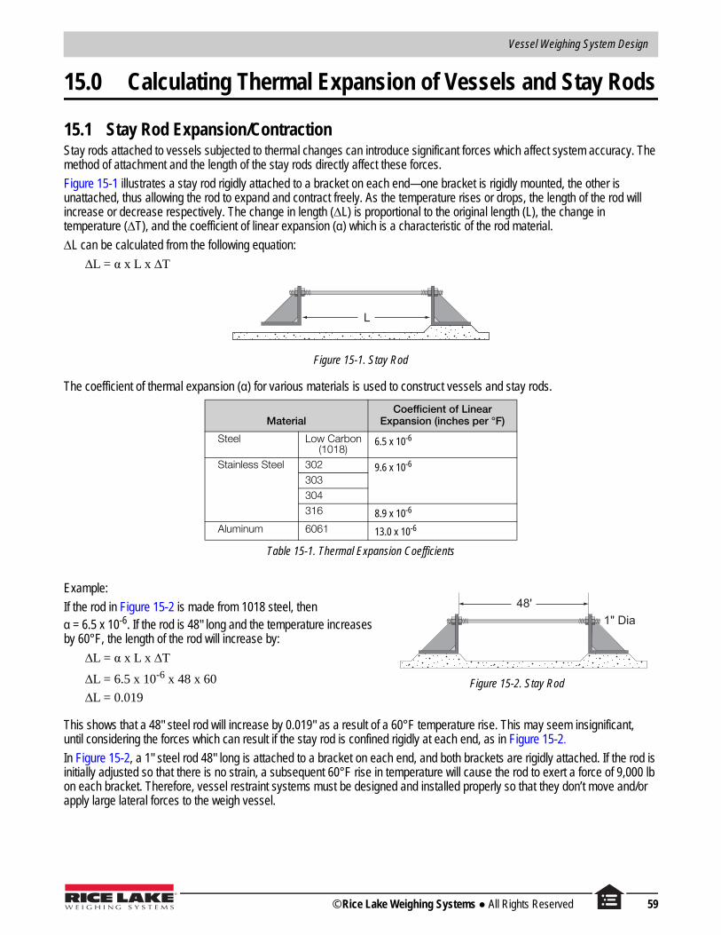
Vessel Weighing System Design
15.0 Calculating Thermal Expansion of Vessels and Stay Rods
15.1 Stay Rod Expansion/ContractionStay rods attached to vessels subjected to thermal changes can introduce significant forces which affect system accuracy. The method of attachment and the length of the stay rods directly affect these forces.
Figure 15-1 illustrates a stay rod rigidly attached to a bracket on each end—one bracket is rigidly mounted, the other is unattached, thus allowing the rod to expand and contract freely. As the temperature rises or drops, the length of the rod will increase or decrease respectively. The change in length (∆L) is proportional to the original length (L), the change in temperature (∆T), and the coefficient of linear expansion (α) which is a characteristic of the rod material.
∆L can be calculated from the following equation:
∆L = α x L x ∆T
Figure 15-1. Stay Rod
The coefficient of thermal expansion (α) for various materials is used to construct vessels and stay rods.
Table 15-1. Thermal Expansion Coefficients
Example:48'
1" Dia
Figure 15-2. Stay Rod
If the rod in Figure 15-2 is made from 1018 steel, then α = 6.5 x 10⁻⁶. If the rod is 48" long and the temperature increases by 60°F, the length of the rod will increase by:
∆L = α x L x ∆T
∆L = 6.5 x 10-6 x 48 x 60
∆L = 0.019
This shows that a 48" steel rod will increase by 0.019" as a result of a 60°F temperature rise. This may seem insignificant, until considering the forces which can result if the stay rod is confined rigidly at each end, as in Figure 15-2.In Figure 15-2, a 1" steel rod 48" long is attached to a bracket on each end, and both brackets are rigidly attached. If the rod is initially adjusted so that there is no strain, a subsequent 60°F rise in temperature will cause the rod to exert a force of 9,000 lb on each bracket. Therefore, vessel restraint systems must be designed and installed properly so that they don’t move and/or apply large lateral forces to the weigh vessel.
MaterialCoefficient of Linear
Expansion (inches per °F)
Steel Low Carbon (1018)
6.5 x 10⁻⁶
Stainless Steel 302 9.6 x 10⁻⁶
303304316 8.9 x 10⁻⁶
Aluminum 6061 13.0 x 10⁻⁶
L
© Rice Lake Weighing Systems All Rights Reserved 59

Load Cell and Weigh Module Handbook
15.2 Vessel Expansion/ContractionTemperature fluctuations will cause weigh vessels to grow and contract. Figure 15-3 illustrates this.
Shown is a top view of a rectangular vessel. The solid line represents its size at 70°F and the inner and outer broken lines represent its size at 40°F and 100°F respectively. The amount that the sides will increase/decrease in length can be found using the expansion formula discussed previously.
144.0"
84.0"
Therefore: ∆L = X x L x ∆T
Figure 15-3. Weigh Vessel Expansion/Contraction
If the vessel is made from mild steel, the length will vary by ± 0.028" (6.5 x 10-6 x 144 x 30), and the width will vary by ± 0.016" (6.5 x 10-6 x 84 x 30) as the temperature fluctuates by ± 30°F. It will be apparent that if the load cell is held rigidly by the mount, enormous side forces will be applied to the cell, hence the need to use a mount which can accommodate vessel expansion/contraction due to changes in temperature.
In the case of a cylindrical vessel Figure 15-4, the change in diameter (∆D) resulting from a change in temperature (∆T) is given by:
∆D = α x D x ∆T
Example:
If a cylindrical vessel is 96" in diameter and made from 304 stainless steel and is subjected to a temperature rise of 80°F as the result of being filled with a hot liquid, then the diameter will increase by:
∆D = 9.6 x 10-6 x 96 x 80= 0.074"
Vessels with attached piping can be subjected to severe side forces as a result of temperature variations if the connections are not executed properly. It is worth noting that vessels expand and contract vertically as well as horizontally with changes in temperature. Rigidly-attached piping may magnify the effects of this expansion, as seen in Figure 15-5. See Attaching Piping to Weigh Vessels in Section 18.0 on page 76 for detailed guidelines on this subject.
Figure 15-5. Weigh Vessel with Rigidly-Attached Piping
D
Figure 15-4. Cylindrical Vessel
60 Visit our website www.ricelake.com

Vessel Weighing System Design
16.0 Calculating Tank Volumes
16.1 Formulas for Tank Shapes and Sections
16.1.1 Cylinder
H
D
Volume =π
D2H4
16.1.2 Portion of Cylinder
h
D
Volume =π
hD28
16.1.3 Horizontal Cylinder (Partially Filled)
h
D L
Volume =π
D2L -π
D2Lcos-1 (2h - D)+ ( h -
D ) L√ hD - h24 720 D 2
If the vessel is filled completely (h = D), then this formula reduces to:
Volume =π
D2L4
If the vessel is filled half way (h = D/2), then this formula reduces to:
Volume =π
D2L8
© Rice Lake Weighing Systems All Rights Reserved 61

Load Cell and Weigh Module Handbook
16.1.4 Frustum of Cone
h
D
d
Volume =π
h(D2 + dD + d2)12
16.1.5 Hemispherical End
D
D2
Volume = πD3
12
16.1.6 Spherical Segment
L
DVolume = πL ( D2
+ L2 )8 6
The radius of the sphere from which the segment is cut is:
r = D3 + 4L2
8 L
Note: r ≠ D/2 (D is the diameter of the vessel)
16.1.7 Hemispherical End (Partially Filled)
h D Volume = π (3h2 D-2h3)12
62 Visit our website www.ricelake.com

Vessel Weighing System Design
16.1.8 Square Prism (Rectangular Cross Section)
H
B
A
Volume = ABH
16.1.9 Square Prism (Square Cross Section)
H
B
A
Volume = A2 H
16.1.10 Wedge I
B
h
a
A
Volume = ( a + A ) Bh2
© Rice Lake Weighing Systems All Rights Reserved 63

Load Cell and Weigh Module Handbook
16.1.11 Wedge II
16.1.12 Frustum of Pyramid
16.2 Angle of ReposeWhen a granular material is dropped from above onto a flat surface it tends to form a cone. The shape of this cone is described by the angle of repose (α), which is a characteristic of the material. The angle of repose varies somewhat with particle size, moisture content, etc. The relationship between α, h, and D is:
The volume of any cone is:
Volume =hAB
2
Volume =h (2AB + Ab + aB + 2ab)6
Volume =Dtanα
2
height x area of base
3
A
B
h
A
a
h
bB
h
D
64 Visit our website www.ricelake.com

Vessel Weighing System Design
In calculating the volume of material in a vessel, an adequate approximation can be made by adding 1/3 of the height of the cone to the height of material up to the cone.For example, assume the height of the material in the cylindrical vessel to be 15' + 1.5' = 16.5 feet.The volume is calculated using the following formula:
16.3 Calculation Examples
Example 1Calculate the volume of liquid in the horizontal tanks shown below. It has hemispherical ends and is filled to a height of 4.5 feet.
For ease of calculation, this can be broken into 3 sections:
Volume =π
D2h = 3.14
x (13)2 x 16.5 = 2190 cubic feet4 4
4.5'
15'
13'
4.5'
3' 20' 3' 3'
(b)(a) (c)
© Rice Lake Weighing Systems All Rights Reserved 65
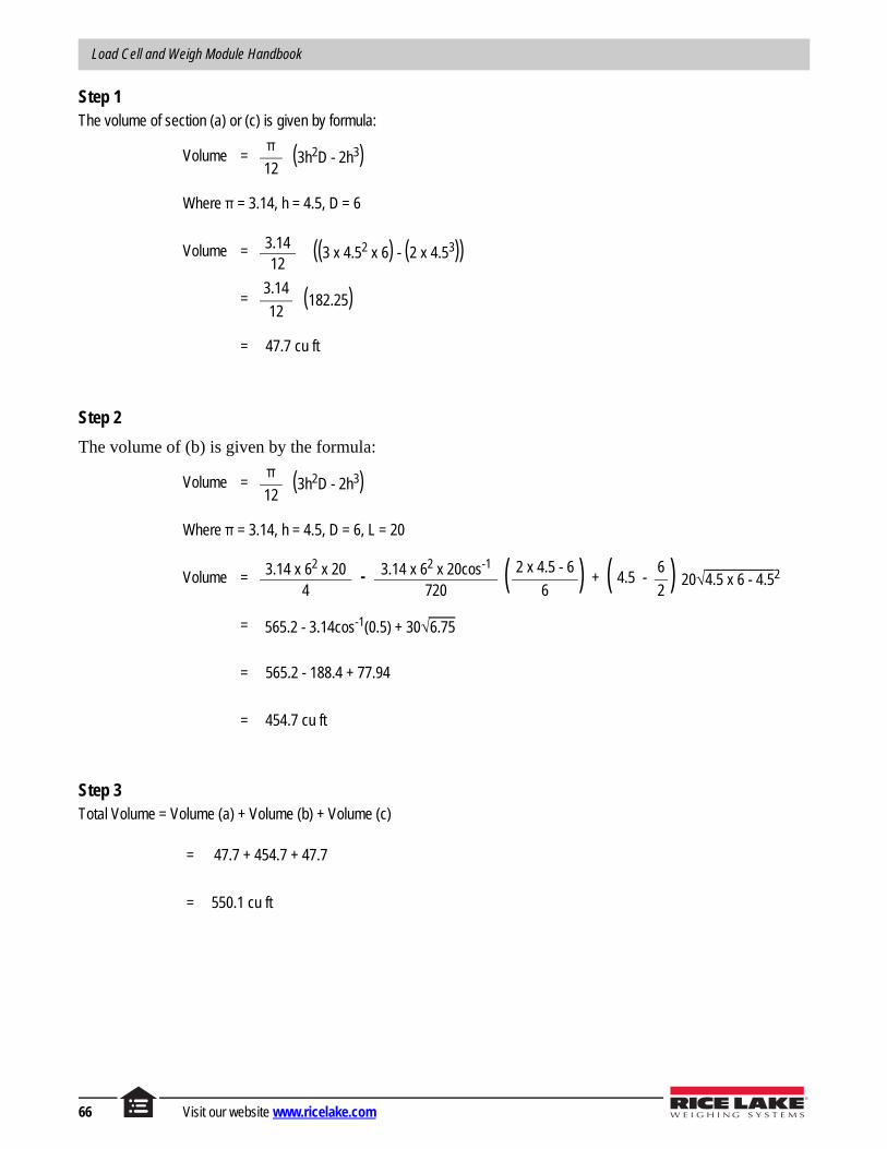
Load Cell and Weigh Module Handbook
Step 1The volume of section (a) or (c) is given by formula:
Step 2
The volume of (b) is given by the formula:
Step 3Total Volume = Volume (a) + Volume (b) + Volume (c)
Volume =π (3h2D - 2h3)12
Where π = 3.14, h = 4.5, D = 6
Volume = 3.14 ((3 x 4.52 x 6) - (2 x 4.53))12
=3.14 (182.25)12
= 47.7 cu ft
Volume =π (3h2D - 2h3)12
Where π = 3.14, h = 4.5, D = 6, L = 20
Volume = 3.14 x 62 x 20 - 3.14 x 62 x 20cos-1 ( 2 x 4.5 - 6 ) + ( 4.5 - 6 ) 20√ 4.5 x 6 - 4.52
4 720 6 2
= 565.2 - 3.14cos-1(0.5) + 30√ 6.75
= 565.2 - 188.4 + 77.94
= 454.7 cu ft
= 47.7 + 454.7 + 47.7
= 550.1 cu ft
66 Visit our website www.ricelake.com

Vessel Weighing System Design
Example 2If, in the last example, the vessel were filled completely, then the volume would be:
Total Volume = Volume (a) + Volume (b) + Volume (c)
Example 3If the vessel in Example 2 is filled with linseed oil, calculate the weight of material when the vessel is full.The density of linseed oil is 58.5 lb/cu ft. From Example 2, we know that the volume of the vessel is 678.2 cu ft.
Example 4Calculate the volume of material in the hopper shown below:
Volume = πD3+ πD2L + πD3
12 4 12
= 3.14(63) + 3.14(62) x 20 + 3.14(63)12 4 12
= 56.5 + 565.2 + 56.5
= 678.2 cu ft
Weight of Material = Volume x Density
Weight of Material = 678.2 x 58.5
Weight of Material = 39,675 lb
5' 7'
5'3'
3'
6'
2'
12'
© Rice Lake Weighing Systems All Rights Reserved 67

Load Cell and Weigh Module Handbook
For ease of calculation, this may be broken into 2 sections as follows:
Step 1The volume of section (a) is given by:
Where leveled height is assumed to be 6.7'
Step 2The volume of section (b) is given by:
Step 3
Example 5
If, in the last example, the vessel was filled to overflowing, then the volume would be:
Total Volume = Volume (a) + Volume (b)
Volume (b) = 73.0 cu ft (same as the previous example)
Volume (a)= 5 x 7 x 9.7 = 339.5 cu ft
Total Volume = 339.5 + 73.0= 412.5 cu ft
Volume = ABh
= 5 x 7 x 6.7
= 234.5 cu ft
Volume =h (2AB + Ab + aB + 2ab)6
Volume =3 ((2 x 5 x 7) + (5 x 5) + (3 x 7) + (2 x 3 x 5))6
=3 (146)6
= 73.0 cu ft
Total Volume = Volume (a) + Volume (b)
= 234.5 + 73.0
= 307.5 cu ft
5'
(a)
6.7'6'
2'
5'
3'
(b)
3'
3'
9.7' Volume (a)
Volume (b)
68 Visit our website www.ricelake.com

Vessel Weighing System Design
17.0 Wind and Seismic Effects on Vessel Stability
17.1 OverviewOther than forces resulting from the impact of a vehicle, wind and seismic forces are the most important external forces which might affect a weigh vessel. The threat from vehicular traffic can be guarded against using properly designed guard rails. The effects of wind and seismic forces, where they are a factor, must be accounted for in the design of a weigh vessel. At a minimum, consideration of these forces might affect the capacity of load cells selected. In more extreme cases they may dictate the use of additional restraints on a vessel. In general, weigh modules have a lift-off capacity of 150% of capacity, and a side-load capacity of 100% of capacity.
Figure 17-1. External Forces on a Weigh Vessel
In general, these forces act horizontally at the center of gravity (CG) of the weigh vessel. Figure 17-1-A illustrates a four-legged vertical cylindrical vessel and the forces acting on it in the absence of wind or seismic forces. W is the vessel’s weight (an empty and full vessel should be considered separately, as either one may be the limiting case), and it acts through the vessel’s center of gravity. Assuming that the four legs are arranged symmetrically, then each leg will exert a force of 1/4W on each mount.
Figure 17-1-B illustrates the same vessel with the addition of a horizontal force F (the result of wind or seismic activity.) The vessel exerts a horizontal force of 1/4 F on each load cell mount. Also, there is an additional force of F0T acting on the left-hand side load cell mounts, which means that each is now carrying a load of 1/4W + F0T. On the right-hand side load cell mounts, a force of F0T is also induced as a result of F, however, this force is in the opposite direction to the existing 1/4W and the total force here is reduced to 1/4W - F0T. Therefore, the load is being transferred from the mounts on one side of the vessel to those on the other. The load cell capacity selected must be capable of withstanding this additional force for the extremes of wind or seismic forces expected. If F was increased to where F0T equaled W/4 then there would be zero load on the right hand mounts and the load would have doubled to W/2 on the left-hand mounts. Further increase in F will cause the vessel to lift up on the right-hand mounts and may, in the extreme case, cause the vessel to tip.
AB
© Rice Lake Weighing Systems All Rights Reserved 69

Load Cell and Weigh Module Handbook
The relationship between F0T and F may be stated as follows for the vessel shown in Figure 17-1:
F0T = 0.7 Fh/D
Where h = height to the center of gravity and D = vessel diameter.
It is desirable to reduce F0T; this can be done by reducing F or h or by increasing D. Dimension h can be reduced by reducing the vessel height (not always practical) or by placing the mounts at the vessel’s center of gravity as illustrated earlier. In this case h = 0 and hence F0T = 0.
It is interesting to compare the stability of a vessel supported on 3 and 4 load cell mounts. Figure 17-2 shows a top view of a vertical cylindrical vessel supported at 3 and 4 points (broken and solid lines respectively). The vessel will tend to tip about a straight line drawn between adjacent support points; the greater the distance from the center of gravity to this line the more stable the vessel will be. A vessel supported at 3 points will be approximately 29% less stable than if it were supported at 4 points.
Figure 17-2. Vertical Cylindrical Vessel Top View
Because of the many variables in vessel design and site conditions, it is impossible to deal comprehensively with the calculation of wind and seismic forces in this text. However, the following subsections deal with these forces in general terms and point out the information necessary for a complete analysis. Refer to the Uniform Building Code (UBC) for further details.
While the effects of both wind and seismic forces should be considered, it is acceptable to consider these forces in isolation.
Top view of cylindrical vessel
.25D .35D
CG
.5D
= Diameter
= Center of Gravity
= 3 point support
= 4 point support
D
CG
70 Visit our website www.ricelake.com

Vessel Weighing System Design
17.2 Wind and Seismic Weigh Module PolicyWind and seismic forces are external forces that may affect a weigh vessel and are substantial considerations when designing a vessel weighing application. With tall, slender vessels, or vessels subject to wind or seismic loads, stability becomes a primary concern.
A structural engineer is required to ensure the vessel and mounts are properly sized and designed for the specific location’s likelihood of damage due to wind and seismic forces (see Figure 17-4 on page 73 and Figure 17-5 on page 74). There are many variables to consider when determining if a system is structurally sound, examples include the geological make-up of the application site and the vessel’s foundation design.
The effects of wind and seismic forces must be accounted for in the design of a weigh vessel on an individual installation basis. Although load cell capacity and the use of additional vessel restraints may be part of the preventative design, site conditions and the extent of wind and seismic forces for the geographic location must also be thoroughly reviewed. Because of the many variables in vessel loading, it is Rice Lake Weighing Systems’ policy to encourage you to follow best practices and review vessel weighing applications with a licensed structural engineer who is familiar with wind and seismic forces.
Rice Lake Weighing Systems can provide the recommended load cell/weigh module force limitations based on a safety factor (SF) from 1 to 5 for Rice Lake manufactured weigh modules. In addition, load cell specifications that a structural engineer will need to determine a complete wind/seismic analysis of the application are available. Rice Lake Weighing Systems recommends using a safety factor of 5 for seismic zone applications, but ultimately, the system should be reviewed and certified by a licensed structural engineer to verify this is sufficient.
If you have any questions about wind and/or seismic forces and how they affect your vessel weighing application, please feel free to contact Rice Lake’s engineering department at 800-472-6703.
© Rice Lake Weighing Systems All Rights Reserved 71

Load Cell and Weigh Module Handbook
17.3 Wind ForcesConsideration must be given to the effects of wind loading when a weigh vessel is installed outdoors. This is particularly important for tall slender vessels, vessels installed in exposed locations (for example, facing a large body of water), or those installed in a high wind-speed location. In analyzing the effects of wind loading, it must be assumed that the wind may blow at a vessel in any horizontal direction.
Figure 17-3 illustrates the effect of wind blowing at a vertical cylindrical vessel. Note that not only is there a force exerted against the windward side of the vessel, but there is also a suction force on the leeward side. These forces are additive, and tend to tip the vessel in the direction of the wind. At right angles to the wind direction are suction forces pulling on each side due to the increased speed of the wind at these points. Since these are equal and opposite in direction, they have no net effect on the stability of the vessel.
Figure 17-3. Wind Forces on a Vertical Cylindrical Vessel
To perform a complete wind force analysis, the following information is necessary:
• Vessel: The vessel’s dead and live weights, number of supports, and overall dimensions such as height, length of legs, diameter, etc.
• Minimum basic wind speed: This may be taken from Figure 17-4 on page 73, which is a map of the USA superimposed with wind speed contours. This map is based on a 50-year mean recurrence interval which has traditionally been accepted as a reasonable risk. If local records indicate higher 50-year wind speeds, then the higher values should be used. This map does not consider the effects of tornadoes.
• Exposure: The exposure conditions at the site must be known. Built up or rough terrain can cause a substantial reduction in wind speed. The United Building Code (UBC) defines 3 exposure categories:
• Exposure B: has terrain with buildings, forest or surface irregularities 20 feet or more in height covering at least 20% of the area extending one mile or more from the site.
• Exposure C: has terrain which is flat and generally open, extending one half mile or more from the site in any full quadrant.
• Exposure D: represents the most severe exposure in areas with basic wind speeds of 80 mph or greater and has terrain which is flat and unobstructed facing large bodies of water over one mile or more in width relative to any quadrant of the vessel site. Exposure D extends inland from the shoreline 1/4 mile or 10 times the vessel height, whichever is greater.
• Importance Factor: An importance factor of 1.15 is used for essential facilities which must be safe and usable for emergency purposes after a windstorm in order to preserve the health and safety of the general public. Such facilities include medical facilities having surgery or emergency treatment areas, fire and police stations. A factor of 1.0 is used for all other facilities.
Wind Direction
72 Visit our website www.ricelake.com

Vessel Weighing System Design
With this information, the wind forces can be calculated in accordance with methods described in the UBC. This information may be used to verify the stability of the vessel using standard mounts, or to design additional restraints if deemed necessary.
Figure 17-4. Wind Speed Contours Map
• Values are fastest mile speeds at 33 feet above ground for Exposure Category C and are associated with an annual probability of 0.02.
• Linear interpolation between wind speed contours is acceptable.• Caution in use of wind speed contours in mountainous regions of Alaska is advised.• Wind speed for Hawaii is 80 and Puerto Rico is 95.• Wind speed for Alaska varies from 70 inland to over 110 in coastal areas. • Where local records or terrain indicate higher 50-year wind speeds, they shall be used.• Wind speed may be assumed to be constant between the coastline and the nearest inland contour.
100
90
100
9080
70
80
70
70
80
70
80
7080
90
80 10090
110
110
110
110100
90
8070
90
80
70
7070
90
90
8070
Basic wind speed 70 mph
Special wind speed region
© Rice Lake Weighing Systems All Rights Reserved 73

Load Cell and Weigh Module Handbook
17.4 Seismic ForcesFigure 17-5 is a seismic zone map of the United States. The zones are numbered 0 (little likelihood of damage) through 4 (likelihood of major damage) which indicate, on an ascending scale, the severity of damage likely as the result of earthquakes. The effects of seismic forces should be considered on vessels being installed in zones 1 through 4.
The following information is required in order to perform a complete seismic analysis.
• Vessel: The vessel’s dead and live weights, number of supports, and overall dimensions such as height, length of legs, diameter, etc.
• The seismic zone (from Figure 17-5) in which the vessel will be installed.• Is the vessel freestanding, mounted on a structure, or on the roof of a building?• Function of structure. Does the vessel:
• Contain material or equipment necessary for the protection of essential facilities (hospitals, fire and police stations), hazardous facilities or special occupancy structures (schools, jails and public utilities)?
• Contain sufficient quantities of toxic or explosive substances to be dangerous to the safety of the general public if released?
• Support the operation of public utility facilities?• Perform a function not listed above.
• Site geology/soil characteristics and the vessel’s structural period, if available.With this information, the forces resulting from seismic activity can be calculated according to methods described in the Uniform Building Code (UBC). A structural engineer and geologist will need to examine vessel design and site location to determine the correct capacity of load cells to be used.
Figure 17-5. Seismic Zone Map
ALASKA
HAWAII1
2B
3
3
1
2B
4
2B
1
0
2B
3
3
4
1
2B
3
3
43
4
3
4
2B
1
1
2B1
1
2B
0
0
0
2A
1
2A
2A
3
0
1
0
0
2A
1
1
1
2A
2A
1
3
2B
74 Visit our website www.ricelake.com

Vessel Attachments
Vessel Attachments
18.0 Attaching Piping to Weigh Vessels . . . . . . . . . . . . . . . . . . . . . . . . . . . . . . . . . . . . . . . . . 7618.1 Example I . . . . . . . . . . . . . . . . . . . . . . . . . . . . . . . . . . . . . . . . . . . . . . . . . . . . . . . . . . . . . . . . . . . . 7718.2 Example 2 . . . . . . . . . . . . . . . . . . . . . . . . . . . . . . . . . . . . . . . . . . . . . . . . . . . . . . . . . . . . . . . . . . . . 79
19.0 Piping Guidelines . . . . . . . . . . . . . . . . . . . . . . . . . . . . . . . . . . . . . . . . . . . . . . . . . . . . . . . 8120.0 Vessel Restraint Systems. . . . . . . . . . . . . . . . . . . . . . . . . . . . . . . . . . . . . . . . . . . . . . . . . 84
20.1 Stay Rods . . . . . . . . . . . . . . . . . . . . . . . . . . . . . . . . . . . . . . . . . . . . . . . . . . . . . . . . . . . . . . . . . . . . 8420.2 Safety Check Rods . . . . . . . . . . . . . . . . . . . . . . . . . . . . . . . . . . . . . . . . . . . . . . . . . . . . . . . . . . . . . 85
21.0 Low-Accuracy Systems: Partial Mounting on Flexures . . . . . . . . . . . . . . . . . . . . . . . . 87
© Rice Lake Weighing Systems All Rights Reserved 75

Load Cell and Weigh Module Handbook
18.0 Attaching Piping to Weigh VesselsAttached piping is by far the largest source of error in vessel weighing; therefore, the piping arrangement must be carefully planned in the design of any weigh vessel.
Figure 18-1 shows a vessel mounted on load cells and supported on an I-beam structure. An attached horizontal pipe is rigidly supported a distance “l” from the vessel.
Figure 18-1. Vessel Application
When the vessel is loaded, it moves downward as shown in Figure 18-2 as a result of:
• The deflection of the load cell (0.005" to 0.015" at full load).• The deflection of the support structure.
Figure 18-2. Deflection of Vessel Application
The attached pipe also deflects downward by the same amount ∆h and it applies an upward force to the tank.
The effects of piping are particularly severe when several pipes are attached to a low-capacity weigh vessel. Through proper design, the upward forces exerted by the pipes can be reduced to a small percentage of the vessel’s live load. Then, by calibrating the vessel with weight, the remaining effects can be compensated for. Calibration using a load cell simulator will not produce accurate results, since there is no way to simulate the effects of attached piping.
l
l
h
76 Visit our website www.ricelake.com

Vessel Attachments
Some common rules for piping design are as follows:
• Reduce deflection of the vessel support structure to a minimum.• Use the smallest diameter, lightest wall pipe possible.• All pipes must run horizontally away from the vessel.• Place the first pipe support 20 to 30 times the pipe diameter away from the vessel (for example, for a 2" diameter pipe,
the first support would be placed at least 40", and preferably 60", away from the vessel).
Pipe diameters and wall thickness, pipe support intervals, etc., must be chosen consistent with the functionality, structural, and reliability requirements of the system in addition to recommendations of this section.
For a more rigorous treatment of the subject, the force F1 exerted on the vessel may be calculated using the following equation:
Where:
D = outside diameter of piped = inside diameter of pipe∆h = total deflection of the pipe at the vessel relative to the fixed point.E = Young’s modulus
=29,000,000 for mild steel=28,000,000 for stainless steel=10,000,000 for aluminum
l = length of pipe from the vessel to the first support point.
This yields conservative results, since it assumes that the pipe is held rigidly at both ends. In practice there will be some give in both the support point and its attachment to the vessel. The following example illustrates the use of this formula.
18.1 Example IA steel tank is supported on load cells and a steel structure with deflections of 0.008" and 0.250" respectively under load. A 4" schedule 40 pipe is attached horizontally with 36" free span between the vessel and the first support point. What force F1 is exerted upward on the vessel?
From the above information:
∆h = 0.008" + 0.250" = 0.258"E (mild steel) = 29,000,000D = 4.50, d = 4.03 (For schedule 40 pipe)l = 36"
Hence:
= 13,840 lb
F1 = 0.59(D4- d 4) x (∆h) x El 3
F1 = 0.59(4.504- 4.034) x (0.258) x 29,000,000363
Note
36"
© Rice Lake Weighing Systems All Rights Reserved 77

Load Cell and Weigh Module Handbook
• Example 1 summarizes the above result. The other lines (Examples 2–5) represent the result when one parameter is changed. The last column on the right expresses the % change in F1 relative to Example 1 (13,840 lb).
• Example 2 shows the effect of doubling the length of pipe between the vessel and first support point. The 87% reduction shows that F1 can be greatly decreased by increasing the distance to the first support point.
• Example 3 shows the effect of cutting the structural deflection in half from 0.250" to 0.125" (the load cell deflection of 0.008" remains the same). It is obvious from the 48% reduction that F1 can be moderately decreased by reducing the vessel’s deflection.
• Example 4 shows the effect of using a lighter-wall schedule 10S pipe instead of schedule 40.• Example 5 shows the effect of reducing the size of the pipe from 4" schedule 40, to 2" schedule 40. From the large 93%
reduction, it is clear why the smallest diameter pipe suitable for the application should be used.
These and other piping guidelines are summarized in Section 19.0 on page 81. Note that while the emphasis here is on attached piping, these recommendations apply equally to attached electrical conduit and cables.
If several pipes are attached to a vessel, the vertical force exerted on the vessel can be calculated for each individually, as described above, then added together to get the total force F acting vertically on the vessel.
That is:
F = F1 + F2 + F3 …
Where F1 is the force exerted by pipe 1, F2 the force exerted by pipe 2, etc.
Accepted practice in the scale industry for ensuring that piping does not adversely affect the required accuracy is to ensure that the following relationship is satisfied:
F ≤ 0.1 x [system accuracy (%)] x [live load (lb)]
For example, if a vessel’s live load is 50,000 lb and a system accuracy of 0.25% is required, then
F ≤ 0.1 x 0.25 x 50,000F ≤ 1,250 lb
i.e., the sum of all vertical pipe forces must be less than or equal to 1,250 lb
Example PipePipe Length
(l)Deflection
(∆h)Upward Force
(F1)Percentage
Reduction in (F1)
1 4″ schedule 40 36″ 0.258 13,840 ---
2 4″ schedule 40 72″ 0.258 1,730 87%
3 4″ schedule 40 36″ 0.133 7,130 48%
4 4″ schedule 10S* 36″ 0.258 7,630 45%
5 2″ schedule 40† 36″ 0.258 976 93%
* For 4″ Schedule 10S, D=4.50, d=4.26; †For 2″ Schedule 40, D=2.38; d=2.16
Table 18-1. Examples
78 Visit our website www.ricelake.com

Vessel Attachments
18.2 Example 2The vessel shown has the following characteristics:
• 40,000 lb live load• Mounted on 4 each 20,000 lb single-ended beams
with full scale deflections of 0.010"• Structure deflection of 0.375"• Accuracy requirement of 0.5%• Material is stainless steel throughout
1. Determine allowable F value:
F ≤ 0.1 x [system accuracy (%)] x [live load (lb)]F ≤ 0.1 x 0.5 x 40,000≤ 2,000 lb
The sum of all vertical pipe forces must be less than or equal to 2,000 lb.
2. Determine total deflection. Since the live load represents only ½ of the load cell capacity, the load cell deflection will be:
Total deflection ∆h = load cell deflection + structure deflection = 0.005 + 0.375 = 0.380"
3. Determine FX for each pipe using the formula:
0.010 = 0.005"
2
FX = 0.59(D4- d 4) x (Dh) x El 3
F1 = 0.59(3.504- 3.074) x 0.380 x 28,000,000723
= 1,029 lb
F2 = 0.59(2.3754- 2.074) x 0.380 x 28,000,000603
= 391 lb
F3 = 0.59(3.504- 3.074) x 0.380 x 28,000,000843
= 648 lb
F4 = 0.59(1.3154- 1.0494) x 0.380 x 28,000,000363
= 239 lb
60"
36"
72"
84"
2" Schedule 10S
3" Schedule 40
3" Schedule 40 Pipe 1
1" Schedule 40
Pipe 3
Pipe 4
Pipe 2
© Rice Lake Weighing Systems All Rights Reserved 79

Load Cell and Weigh Module Handbook
4. Determine F using the formula:
Since F calculated for the vessel is greater than the value determined in Step 1, this is not acceptable. There are several solutions.
• Accept a lower accuracy (perhaps 1%, instead of 0.5%)• Reduce the deflection of the support structure• Improve the piping by:
• using smaller, lighter pipes• use flexible hose or bellows• increase the distance to the first pipe support points
If we apply the third bullet, improve the piping by increasing the distance to the first pipe support points, then we would focus our attention on the main offender, pipe 1. The problem can be solved simply by increasing the distance to the first support from 72" to 82", yielding an F1 = 697 lb.
Therefore, F = 697 + 391 + 648 + 239 = 1,975 lb.This is less than 2,000 lb and the design is now acceptable.
F = F1 + F2 + F3 + F4
= 1,029 + 391 + 648 + 239
= 2,307 lb
80 Visit our website www.ricelake.com

Vessel Attachments
19.0 Piping Guidelines
Incorrect Piping Guidelines Correct
Use the smallest diameter pipe suitable for the application.
Use the lightest wall pipe suitable for the appli-cation.
Do not attach pipes directly to the vessel if pos-sible (vented systems). Allow them to enter through large clearance holes. Flexible boots may be used to seal out dust if necessary.
Do not run an attached pipe vertically to its first support point. This will suspend the vessel and destroy accuracy. All pipes should be run horizontally away from the vessel.
Increase the distance between the vessel and the first pipe support.
Avoid long vertical runs of pipe, particularly when they are restrained from vertical move-ment. This is because any thermally induced expansion/contraction of the vertical pipe will be translated into detrimental vertical forces on the vessel, directly affecting accuracy.
Use flexible hose to make the connection to the vessel. Do not use the flexible hose to compensate for an initial offset in the pipes.
Table 19-1. Piping Guidelines
© Rice Lake Weighing Systems All Rights Reserved 81

Load Cell and Weigh Module Handbook
Use flexible bellows to make the connection to the vessel, if possible. Do not use the bellows to compensate for an initial offset in the pipes. Two bellows may be used in series where large deflections must be accommodated.
Placing a right angle bend in the pipe in a hor-izontal plane greatly reduces the stiffness of the pipe. Pipe supports should be used to strengthen the positioning of the pipe.
Avoid tilting of the weigh vessel as a result of non-uniform support stiffness. Small rotations of the vessel can be amplified into large move-ments at the first support.
Do not support pipes on a structure which may deflect independently of the vessel. Do sup-port pipes from the vessel’s support structure so that the support point moves with the ves-sel, thus reducing the relative deflection.
Do not attach all pipes to the same side of the vessel. Arrange them symmetrically around its diameter, as far as possible.
Incorrect Piping Guidelines Correct
Table 19-1. Piping Guidelines (Continued)
82 Visit our website www.ricelake.com

Vessel Attachments
When attaching pipes to a vessel partially mounted on flexures, extra care must be exer-cised to avoid side forces induced by thermal expansion/contraction of the pipes. Use flexi-ble hose, bellows, or a loop, and attach the pipes relative to the load cells/flexures, as shown, to minimize the transfer of weight from the flexures to the cells or vice versa.
With horizontal vessels partially mounted on flexures, do not attach pipes at the live end. Attach pipes over the flexures if possible, since any vertical forces exerted there are not “seen” by the load cells.
Fill pipes for liquids should enter horizontally so that impingement of in-flight material has minimal effect on the weight reading.
With granular materials, fill the vessel sym-metrically. Use a deflector cone to help distrib-ute/level the material.
Do not use rubber pads or other devices which will increase the deflection of the vessel under load. Strengthen the support structure to reduce deflection.
Do not allow a common discharge pipe to hang directly from the vessels. In the example at left, discharging tank B will temporarily add weight to tank A. For a better installation, sup-port the pipes independently.
Flexible electrical cables should not run verti-cally to a weigh vessel; they should run hori-zontally or provide a loop as shown.
Incorrect Piping Guidelines Correct
Table 19-1. Piping Guidelines (Continued)
Load Cells
Flexures
Flexure Module FlexureModule
A B
© Rice Lake Weighing Systems All Rights Reserved 83

Load Cell and Weigh Module Handbook
20.0 Vessel Restraint SystemsWhile many of the mounting arrangements offered by Rice Lake Weighing Systems are self checking, there are situations where additional vessel restraints may be required to steady a vessel subjected to constant vibration, or to restrain a vessel from toppling or falling in the event of some unforeseen circumstance. Two main types of restraint systems are stay rods and check rods.
20.1 Stay RodsStay rods are used to rigidly restrain a vessel in the horizontal direction. These rods are installed horizontally in tension\between a bracket on the vessel and a bracket attached to the vessel’s support structure or foundation. Because of the negligible deflection of load cells under load, the stay rods will have little effect on the accuracy of the system when installed properly. It is necessary to install a number of rods to restrict a vessel fully in a horizontal plane; see Figure 20-1. On a circular vessel, the rods should always be tangential. This prevents the vessel from shifting in any direction, but leaves it free for thermal expansion/contraction.
Figure 20-2 illustrates stay rods attached to a suspended vessel. The rods must be horizontal so that they do not affect the weighing accuracy. Fastening nuts are tightened so the rod is snug; do not over-tighten. This placement of the nuts ensures the rods operate in tension and are never subjected to a compressive or buckling load.
Stay rods are used to:• Improve system stability and accuracy by limiting vessel oscillation or vibration.• Protect piping from fatigue due to constant vessel movement.• Ensure the stability of tall slender vessels or vessels with heavy eccentrically mounted equipment.• Ensure the stability of vessels against wind, seismic forces or threat from vehicular traffic.• Hold a vessel in place when mounted on canister cells. These cells have very little tolerance of side forces and must be
loaded in the vertical direction only.
Figure 20-1. Stay Rod Applications
84 Visit our website www.ricelake.com

Vessel Attachments
Figure 20-2. Stay Rod Application
When using stay rods to provide vessel stability, they are most effective when attached at or above the center of gravity of the filled vessel. Stay rods should be made as long as practical, as this will be beneficial in reducing forces in the vertical direction. It should be emphasized that the rods must be horizontal; for this reason one of the attachment points should be adjustable in a vertical direction.
20.2 Safety Check RodsSafety check rods are similar to stay rods in that they may be applied to a vessel in similar fashion as stay rods. However, they are fitted loosely to the vessel and may also be applied in a vertical direction.
Safety check rods are left loose so that under normal operation they do not apply any axial forces to the weigh vessel. They are not an active part of the weigh system. The safety check rods shown do add to the tare weight of the vessel, but this is constant and does not affect the weighing accuracy. Safety check rods are, as the name implies, a safety feature intended to restrain the vessel if and when it is subjected to large external or internal forces or if there is a mechanical failure in the vessel’s normal support mechanism.
Horizontal safety check rods should be used to:• Ensure the stability of tall slender vessels or vessels with heavy eccentrically mounted equipment.• Ensure the stability of vessels against wind or seismic forces or threat from vehicular traffic.
As shown in Figure 20-3 (a), to be most effective, safety check rods must be fitted at or above the filled vessel’s center of gravity. Note that stay rods will perform all these functions and more; however, safety check rods are less critical to system operation and therefore do not require the same attention to detail for successful installation.
Vertical safety check rods should be used:• On all vessels mounted in tension where failure of the normal suspension means would allow the vessel to fall and cause
injury or damage, see Figure 20-3 (b).• In place of horizontal check rods when it is not practical to use these to ensure the stability of tall slender vessels or
those subjected to wind or seismic forces, see Figure 20-3 (c).Vertical safety rods must be installed in an oversized hole in the lower bracket so that they do not interfere in any way with the vertical movement of the vessel.
For more information, see Section 15.0 on page 59.
Note
© Rice Lake Weighing Systems All Rights Reserved 85

Load Cell and Weigh Module Handbook
Figure 20-3. Safety Check Rods
(a)
(b) (c)
86 Visit our website www.ricelake.com

Vessel Attachments
21.0 Low-Accuracy Systems: Partial Mounting on FlexuresAs noted earlier, low-accuracy weigh systems may be partially supported on flexures if the following conditions are met:
• The vessel contents are self-leveling.• The vessel is symmetrical around a vertical line through the content’s center of gravity.
These restrictions ensure that as the vessel fills, the center of gravity of the contents rises along a vertical line whose location is fixed relative to the support points. This ensures that each load cell always sees the same proportion of the load.
The horizontal cylindrical tank illustrated in Figure 21-1 is mounted on two flexures at one end and two load cells at the other.
It is very important that the vessel is level and the ends are identical in shape. This is a lower-cost weighing system which will work satisfactorily if low accuracy is acceptable.
Figure 21-1. Horizontal Cylindrical Tank Application
Flexures may also be used with tension applications. Figure 21-2 is an example of a circular vessel suspended from one load cell and two flexures (or simply tension rods in this case).
Care must be taken to separate the flexures and load cells to opposite sides or ends of the vessel. In Figure 21-2, for example, the flexures could not be placed on one diagonal and the load cells on the other.
If these vessels are to be calibrated electrically, then the geometry of the vessel must be known accurately. This allows the percentage of the load carried by the load cell(s) to be calculated. A practical alternative is to calibrate with a known weight of liquid. It is not practical to calibrate these vessels with test weights since they could not be placed with any precision at the center of the vessel.
These arrangements should be avoided when the potential exists for weight to be transferred from one support to another. This can be caused by wind-loading, thermal expansion/contraction of pipes, etc.
Figure 21-2. Suspended Circular Vessel Application
© Rice Lake Weighing Systems All Rights Reserved 87

Load Cell and Weigh Module Handbook
88 Visit our website www.ricelake.com

Installation and Service Tips
Installation and Service Tips
22.0 Determining Microvolts per Graduation . . . . . . . . . . . . . . . . . . . . . . . . . . . . . . . . . . . . . 9023.0 Load Cell Mounting Hardware Safety Guidelines . . . . . . . . . . . . . . . . . . . . . . . . . . . . . 91
23.1 Safety Backup . . . . . . . . . . . . . . . . . . . . . . . . . . . . . . . . . . . . . . . . . . . . . . . . . . . . . . . . . . . . . . . . . 9123.2 Estimating Gross Load . . . . . . . . . . . . . . . . . . . . . . . . . . . . . . . . . . . . . . . . . . . . . . . . . . . . . . . . . . 9123.3 Safe Load . . . . . . . . . . . . . . . . . . . . . . . . . . . . . . . . . . . . . . . . . . . . . . . . . . . . . . . . . . . . . . . . . . . . 9123.4 Load Distribution . . . . . . . . . . . . . . . . . . . . . . . . . . . . . . . . . . . . . . . . . . . . . . . . . . . . . . . . . . . . . . . 9123.5 Threaded Connections . . . . . . . . . . . . . . . . . . . . . . . . . . . . . . . . . . . . . . . . . . . . . . . . . . . . . . . . . . 9123.6 Jam Nuts . . . . . . . . . . . . . . . . . . . . . . . . . . . . . . . . . . . . . . . . . . . . . . . . . . . . . . . . . . . . . . . . . . . . . 9123.7 Wire Rope Assemblies . . . . . . . . . . . . . . . . . . . . . . . . . . . . . . . . . . . . . . . . . . . . . . . . . . . . . . . . . . 9123.8 Attachment Points of a Load Cell Hardware Assembly. . . . . . . . . . . . . . . . . . . . . . . . . . . . . . . . . . 9123.9 Swaying in a Suspended Vessel Scale . . . . . . . . . . . . . . . . . . . . . . . . . . . . . . . . . . . . . . . . . . . . . . 9123.10 Hopper Scales: Guarding Against Contamination. . . . . . . . . . . . . . . . . . . . . . . . . . . . . . . . . . . . . . 9123.11 Selecting Steel Rod or Any Other Weight-Bearing Components . . . . . . . . . . . . . . . . . . . . . . . . . . 92
24.0 Load Cell Trimming. . . . . . . . . . . . . . . . . . . . . . . . . . . . . . . . . . . . . . . . . . . . . . . . . . . . . . 9324.1 Load Cell Trimming . . . . . . . . . . . . . . . . . . . . . . . . . . . . . . . . . . . . . . . . . . . . . . . . . . . . . . . . . . . . . 9324.2 Excitation Trim. . . . . . . . . . . . . . . . . . . . . . . . . . . . . . . . . . . . . . . . . . . . . . . . . . . . . . . . . . . . . . . . . 93
24.2.1 Excitation Trimming Procedure. . . . . . . . . . . . . . . . . . . . . . . . . . . . . . . . . . . . . . . . . . . . 9324.3 Signal Trim . . . . . . . . . . . . . . . . . . . . . . . . . . . . . . . . . . . . . . . . . . . . . . . . . . . . . . . . . . . . . . . . . . . 9424.4 What is mV/V/Ohm Calibration? . . . . . . . . . . . . . . . . . . . . . . . . . . . . . . . . . . . . . . . . . . . . . . . . . . . 95
24.4.1 Traditional Approach. . . . . . . . . . . . . . . . . . . . . . . . . . . . . . . . . . . . . . . . . . . . . . . . . . . . 9524.4.2 Paramounts. . . . . . . . . . . . . . . . . . . . . . . . . . . . . . . . . . . . . . . . . . . . . . . . . . . . . . . . . . . 96
25.0 Load Cell Troubleshooting. . . . . . . . . . . . . . . . . . . . . . . . . . . . . . . . . . . . . . . . . . . . . . . . 9725.1 Physical Inspection . . . . . . . . . . . . . . . . . . . . . . . . . . . . . . . . . . . . . . . . . . . . . . . . . . . . . . . . . . . . . 9725.2 Zero Balance . . . . . . . . . . . . . . . . . . . . . . . . . . . . . . . . . . . . . . . . . . . . . . . . . . . . . . . . . . . . . . . . . . 9725.3 Bridge Resistance . . . . . . . . . . . . . . . . . . . . . . . . . . . . . . . . . . . . . . . . . . . . . . . . . . . . . . . . . . . . . . 9825.4 Resistance to Ground . . . . . . . . . . . . . . . . . . . . . . . . . . . . . . . . . . . . . . . . . . . . . . . . . . . . . . . . . . . 99
26.0 Calibration Guidelines for Vessel Weighing Systems. . . . . . . . . . . . . . . . . . . . . . . . . . 9926.1 Calibration Using Certified Test Weights. . . . . . . . . . . . . . . . . . . . . . . . . . . . . . . . . . . . . . . . . . . . . 9926.2 Calibration Using Weighed Material . . . . . . . . . . . . . . . . . . . . . . . . . . . . . . . . . . . . . . . . . . . . . . . 10026.3 Calibration Using Material Substitution Method . . . . . . . . . . . . . . . . . . . . . . . . . . . . . . . . . . . . . . 10026.4 Calibration Using A Load Cell Simulator . . . . . . . . . . . . . . . . . . . . . . . . . . . . . . . . . . . . . . . . . . . . 101
© Rice Lake Weighing Systems All Rights Reserved 89

Load Cell and Weigh Module Handbook
22.0 Determining Microvolts per GraduationWhether sizing load cells for a mechanical conversion, replacing truck scale cells, or designing a weighing vessel, it’s tempting to pick a grossly oversized load cell for “overload insurance.” This practice can create a problem that can cost many hours in troubleshooting and redesign. If the capacity is oversized too much, the signal output may be cut to a point where the system will not operate as planned. Determining the application’s required microvolts per graduation (µV/grad) will allow for properly sizing of a load cell, ensuring adequate signal and overload protection.
The signal sensitivity of electronic digital weight indicators is specified as a minimum microvolt per graduation value. A microvolt (µV) is one millionth of a volt. The µV per graduation value is the amount of scale output signal change required to change the meter display one graduation. If the scale output signal is below this value, the meter will not perform properly.
The following process will help to determine the µV per graduation rating of the weighing system:
1. Determine full scale output of the load cell (output signal at 100% of capacity). For example: A cell rated at 3.0 mV/V, when supplied with 10 V of excitation from a digital weight indicator, will provide 30 mV of full scale output.
3.0 mV/V x 10 V = 30 mV
2. Determine how much of the output will be caused by the live load in the application. If the cell has a capacity of 500 lb and the live load placed on it is 300 lb, then 60% of the total capacity of the cell is live load.
3. Determine how much signal represents the live load by multiplying full scale load cell output by the actual amount of live loadat full scale.
30mV x 0.5 = 15 mV
4. Actual µV/graduation rating is determined by dividing the live load signal by the number of graduations the electronic digitalweight indicator is programmed to read. If the indicator is set for 5,000 graduations then:
If the µV/graduation rating was less than the minimum sensitivity rating on the indicator, the installation will not work. The live load signal needs to be increased. How can this be done?
Increase the excitation level. In #1, if 15 V of excitation were used instead of 10 V, then 15 x 3.0 mV/V = 45 mV. By completing the rest of the formula, the µV/graduation would be 4.5 µV.
Use a cell with higher full scale output. This works if the original cell was less than 3.0 mV/V; generally few standard cells are available with more than 3.0 mV/V output.
Counterbalance the dead load off the load cell. This may allow the use of a smaller capacity load cell, thus raising the µV rating, as a greater portion of the total output will be live load signal.
If a signal problem is experienced, using an oversized load cell will worsen the µV/graduation rating. This is because even less of the full scale output would be live load signal. As an example, if a 1000 lb cell were in the given example instead of a 500 lb cell, only 25% of the capacity would be used.
This would give a µV/graduation of:
250 = 0.50 or 50%
500
15 mV = 3.0 μV/graduation
5000 grads
30 mV x 25% = 1.5 μV/graduation
5000 grads
CAUTION
90 Visit our website www.ricelake.com

Installation and Service Tips
23.0 Load Cell Mounting Hardware Safety GuidelinesInstall only load cell mounting hardware and assemblies that have been specifically designed for use in tank, hopper or hanging scale applications. Often, the use of an inferior-grade product results in component failure, which risks equipment damage and personal injury. These simple suggestions are provided to help minimize the exposure to vessel-scale installation hazards.
23.1 Safety BackupIf failure of one or more load cell hardware assemblies could cause injury or damage, a safety backup (safety chains, safety rods, etc.) must be used. The assemblies must be inspected routinely for damage, excessive wear or corrosion, and replaced if necessary.
23.2 Estimating Gross LoadTo select the correct load cell or load cell hardware for a given application, it is necessary to know the total weight on the scale, including the net weight of product, the tare weight of the vessel, and the weight of the platform, tank or hopper, as appropriate.
23.3 Safe Load Do not exceed the safe-load figures listed in this catalog for any load cell hardware. Where shock loads are present, it may be necessary to derate these safe-load figures depending on the severity of the shock load.
23.4 Load DistributionIn multiple load cell applications, make certain that the weight is evenly distributed between all cells.
23.5 Threaded ConnectionsBe sure that all threads of a threaded connection are in engagement. For example, an eye bolt that is screwed into an S-type load cell should protrude slightly on the opposite side.
23.6 Jam NutsLock any threaded connections with a jam nut to prevent inadvertent disassembly. If a load is suspended from a single load cell, make sure the load cannot rotate, as this may loosen the jam nut.
23.7 Wire Rope AssembliesWith wire rope assemblies, do not twist the rope during assembly or disassembly. For example, do not remove a frozen nut from one end of a rope assembly by holding the opposite end. Do not use wire ropes to suspend a load without use of safety chains or safety rods.
23.8 Attachment Points of a Load Cell Hardware AssemblyEnsure that the attachment points of a load cell hardware assembly are aligned properly and that the assembly is essentially vertical.
23.9 Swaying in a Suspended Vessel ScaleIf there is excessive swaying in a suspended vessel scale, apply horizontal checking to reduce the amplitude.
23.10 Hopper Scales: Guarding Against ContaminationWith hopper scales, guard against contamination of the product being weighed as a result of the failure of the load cell or hardware assembly. For example, do not locate a wire rope assembly over a hopper scale where broken strands of wire could fall into the weighing vessel, contaminating the product being weighed.
© Rice Lake Weighing Systems All Rights Reserved 91

Load Cell and Weigh Module Handbook
23.11 Selecting Steel Rod or Any Other Weight-Bearing ComponentsSelect steel rod or any other weight-bearing components so that their minimum tensile strength is at least four times the total weight carried by that component. Note that threaded rod is generally made from a low tensile strength mild steel which should be checked for tensile strength before use in any suspended vessel scale.
Based on dry assembly. Variables such as lubrication, plating, etc. may reduce the values listed above as much as 20% and must be taken into consideration. General formula for calculating torque is as follows: Torque in Inch/lb = 0.2 x Nominal Diameter of Screw x Load in lb, where load = 80% of yield strength, expressed in lb, not pounds per square inch. The tension induced in a cap screw may be checked by measuring overall length before torquing.
Cap screw diameter
Recommended Torque (ft lb)
Heat-treated 1038 hex head SAE Grade 5
Alloy hex head SAE Grade 5
UNC UNF UNC UNF
1/4" 11 13 12 15
5/16" 21 23 25 30
3/8" 38 40 50 60
7/16" 55 60 85 95
1/2" 85 95 125 140
9/16" 125 140 175 195
5/8" 175 210 245 270
3/4" 300 330 425 460
7/8" 450 490 660 700
1" 680 715 990 1050
1-1/8" 885 990 1470 1655
1-1/4" 1255 1380 2100 2310
1-3/8" 1635 1875 2750 3110
1/4" 11 13 12 15
Table 23-1. Steel Rod Tensile Strength
Note
92 Visit our website www.ricelake.com

Installation and Service Tips
24.0 Load Cell TrimmingIt may be necessary to trim the load cell outputs as a first step before starting the calibration process. Trimming is performed at the junction box to equalize the weight reading from all cells in a system. This ensures that the scale weighs correctly regardless of where the load is applied to the scale.
Trimming is necessary if:1. It is a legal-for-trade weighing application.
*2. The location of the center of gravity of the contents is not fixed, e.g., powder material which may accumulate on one side.
*3. A high-accuracy weighing system is required.
Trimming is not necessary if:4. Matched output load cells are used (as in the Paramounts).
5. Weighing self-leveling materials (liquids).
6. The vessel is partially supported on flexures.
*Assume that the vessel’s center of gravity (see 2 and 3 above) rises along the same vertical line as the vessel is filled. Each load cell is always subjected to the same percentage of the weight.
Trimming involves placing the same weight over each load cell in turn, and adjusting the corresponding trim pot in the junction box until the indicator reads the same for all cells. To further illustrate load cell trimming, please review the following examples of signal trim and excitation trimming procedures.
24.1 Load Cell TrimmingMany weighing systems use multiple load cells and therefore require a summing junction box to tie or “sum” the load cell signals together, allowing a digital weight indicator to read a single “system” signal. The summing process actually wires multiple load cells so that all their signal lines and excitation lines are in parallel, providing instantaneous electronic summing of the signals.
Load cell summing is necessary because:
• Weight distribution in multiple load cell systems is not equal at each load cell. The vessel loading process, presence of agitators, and the characteristics of the material and many other factors affect weight distribution on the load cells.
• It is virtually impossible to make each load cell exactly alike. Load cell manufacturing process tolerances allow for some variance in individual cell specifications. This variance, if unchecked, would not allow for the kinds of accuracy required in modern process applications.
There are two summing methods: excitation trim and signal trim.
24.2 Excitation TrimThis is the oldest method of trimming the output from a strain gauge load cell. Excitation trimming adds series resistance to the excitation circuit of the load cell, thereby reducing the excitation voltage at the cell. The load cell with the lowest mV/V output receives the full excitation voltage. All other load cells in the system with a higher mV/V output receive proportionally smaller excitation voltages. This results in matched full load outputs for all load cells in the system.
Figure 24-1 on page 94 is a functional diagram of an excitation trim J-box. Note that a variable resistor or potentiometer (pot), is inserted in the + excitation lead of each load cell. If the pot is opened so that resistance is zero, the full excitation voltage is applied to the load cell. As resistance is increased, excitation voltage decreases.
24.2.1 Excitation Trimming ProcedureThe simplest method of trimming with excitation is to set up the system, turn all trim pots to the “open” or full excitation setting, and test each corner of the system with a calibrated test weight or any dead weight. Once the lowest output corner is located, the other cells are trimmed to match by physically loading with the same weights and adjusting the pots. This procedure can be practical if used in field replacement of load cells in light-capacity floor scales. It is not typically used in heavy-capacity scales where application of test weights to corners in such a manner is not practical.
© Rice Lake Weighing Systems All Rights Reserved 93

Load Cell and Weigh Module Handbook
Another method is pretrimming. Here, the load cells are trimmed by mathematically calculating the excitation voltage for the load cell, then measuring the excitation voltage with a voltmeter, while adjusting the pot to the required voltage. The following five steps walk through this procedure.
Figure 24-1. Excitation Trimming Load Cells
1. Determine how much excitation voltage the electronic digital weight indicator is supplying to the load cells. This is found by measuring, with a voltmeter, the actual excitation voltage present at the reference cell’s excitation leads. For this example, use 10 volts DC.
The reference cell is the cell with the lowest mV/V rating, as shown on its calibration certificate.
2. Determine the exact mV/V rating of each load cell and locate the cell with the lowest rating. The exact mV/V rating is found on the calibration certificate supplied with the load cell or on the label itself. Just because a cell is rated at 3 mV/V, don’t assume it’s exactly 3 mV/V.#1 = 2.997 mV/V #3 = 2.999 mV/V#2 = 3.003 mV/V #4 = 3.002 mV/VCell number 1 has the lowest rating at 2.997 mV/V.
3. Calculate the trimming factor by multiplying the lowest mV/V by the excitation voltage.2.997 mV/V x 10V = 29.970 mV
4. Calculate the adjusted excitation voltage for the remaining load cells and adjust each respective trim pot to the appropriate voltage level.#1 = leave alone, lowest mV/V#2 = 29.97 mV ÷ 3.003 mV/V = 9.980 volts#3 = 29.97 mV ÷ 2.999 mV/V = 9.993 volts#4 = 29.97 mV ÷ 3.002 mV/V = 9.983 voltsThe scale is now trimmed.
5. Verify the results with certified test weights or a known amount of material.
24.3 Signal TrimThis form of trimming first appeared as an alternative to excitation trimming for indicators with gated power supplies. Because of the compatibility that signal trimming has with virtually all indicators and its relative immunity to temperature and vibration problems, signal trimming is gaining popularity for all installations. It involves adding a relatively high parallel resistance between the signal leads of each load cell as shown in Figure 24-2. The added parallel resistance creates a “leakage path” that shunts some of the available load cell signal away from the indicator. The larger this parallel resistance, the more signal available to the indicator from the load cell. Conversely, the smaller this parallel resistance, the less signal available to the indicator from the load cell.
TRIM POT
EXCITATION
+
- SIGNAL
+
-
Note
94 Visit our website www.ricelake.com

Installation and Service Tips
Figure 24-2. Signal Trimming Procedure
24.4 What is mV/V/Ohm Calibration?The Paramounts Vessel Weighing System utilizes a unique system of mV/V/ohm calibration to ensure that all their load cell outputs match precisely. While there are other manufacturers who offer a similar calibration concept, there are important technical differences provided with Flintab products. To understand these differences, let's first review the "traditional" method of matching load cell outputs.
24.4.1 Traditional ApproachThe conventional approach adjusts the short circuit current (mV/ V/ohm) of each load cell to a standard value, within a close tolerance. This does, indeed, ensure that multiple load cell systems will be "corner adjusted" without further trimming, providing there are no mechanical load introduction asymmetries. It also ensures that the system corner adjustment is preserved, even when a load cell is subsequently replaced. It does not, however, preserve the system calibration.
Let's look at this using a simple two-load cell example. Extension to the "n" load cell case is straightforward. In the figure below, two identical load cells are assumed and the conventional equations for
Figure 24-3. Two-Load Cell Example
Where V1 and V2 are voltage sources, R1 and R2 are resistances. It is easier to understand the concepts by using the Norton equivalent circuit. Here, we have two current sources driving currents through the parallel combination of the load cell source impedances. The currents are the short circuit currents (I) of the respective load cell (mV/V/ohm) and they are set equal to some standard value. Note that the mV/V output is the same as in the arrangement above.
Figure 24-4. Norton Equivalent Circuit
TRIM POT
EXCITATION
+
- SIGNAL
+
-
R1 R2 V0 = 1 + 2+1 2+ 2+1 ++
V I =
V0 = x
RR R + R = V
R
V R
V R +
I I
© Rice Lake Weighing Systems All Rights Reserved 95

Load Cell and Weigh Module Handbook
In either case, the system is "cornered." That is, the system output is the same whether the load cells are equally loaded or all the load is on one or the other load cell. Now let's replace the right hand load cell with a unit which has a source resistance that is 2% higher than the load cell it replaced. Since it must have the same short circuit current (mV/V/ohm), its open circuit output voltage will be set 2%.
Now we have the two current generators driving their currents through the parallel combination of their source impedances as before. The system is still "cornered" but the system output is 1% higher, because the parallel combination of the two source impedances is now 1% higher, or the open circuit output voltage of the replacement load cell is 2% higher. So, the system must be recalibrated! This can be a difficult task, especially with high-capacity vessel scales. Unfortunately, the conventional approach does nothing to avoid the need for recalibration after load cell replacement.
24.4.2 ParamountsGiven the same set of circumstances regarding the replacement load cell (source impedance 2% higher), the short circuit current is set to the standard value, as before, but the open circuit voltage is adjusted to a standard value by loading the output terminals with resistance that drops the output voltage of the replacement load cell to the standard value. In this example, a resistance of 51R is placed across the output terminals of the replacement load cell and that additional resistor is shown added to the paralleled source resistances in the figure below.
Figure 24-5. Norton Equivalent Circuit with Additional Resistor
Now the standardized current sources are driving their short circuit currents through the paralleled source resistances; the third resistance, the paralleled combination of the three resistances, is now equaling the original value of R/2. Hence the output voltage with the replacement load cell in place is the same as it was before the replacement. Not only is the system still "cornered," but the system calibration has been maintained. There is no need for system recalibration after load cell replacement. All Flintab SB4 and UB1 load cells are factory-calibrated in the above manner.
1.01 Vx1.02 RR2.02 RV0 = V
R V R+ = V
RI = 1.02 V1.02 R =
= Vx(1.02) (51) R3
(1.02) (51) R2 + 1.02 R2 + 51 R2
2 V R x R
2V0 = V
R V R+ =
I I
96 Visit our website www.ricelake.com

Installation and Service Tips
25.0 Load Cell TroubleshootingHere are some easy-to-follow steps to help troubleshoot potential load cell problems. Before beginning, a good quality digital multimeter and at least a 4½ digit ohm meter will be needed. The tests are: physical inspection, zero balance, bridge resistance and resistance to ground.
25.1 Physical InspectionHow does it look? If it is covered with rust, corroded or badly oxidized, chances are the corrosion has worked its way into the strain gauge area as well. If the general and physical condition appear good, then look at specifics: sealing areas, the element itself, and the cable.
In most load cells, areas of the load cell are sealed to protect the contents from contamination by water and chemicals. To see if any seals have been degraded, get right up close to the cell and look at the strain gauge seals (Figure 25-1 points A). Is rust concentrated on a part of the cover weld? If there is no cover, look to see if there are any tiny holes in the potting. These are indications that there has been contamination to the gauge area. Check the load cell cable entrance (Figure 25-1 point B) for signs of contamination.
Figure 25-1. Load Cell
Other items to look for: metal distortion or cracks, metal rippling, cracks in the weld, or abrasions in the metal. It may be necessary to remove the load cell and check it for physical distortion against a straight edge.
No inspection would be complete without thoroughly inspecting the cable. Cable should be free of cuts, crimps and abrasions. If the cable is cut and in a wet environment, water or chemicals can “wick” up the cable into the strain gauge area, causing load cell failure.
If your physical inspection fails to uncover any identifiable damage, a more detailed evaluation is required.
25.2 Zero BalanceThis test is effective in determining if the load cell has been subjected to a physical distortion, possibly caused by overload, shock load or metal fatigue. Before beginning the test, the load cell must be in a “no load” condition. That is, the cell should be removed from the scale or the dead load must be counterbalanced.
Now that the cell is not under any load, disconnect the signal leads and measure the voltage across the negative signal and positive signal. The color code for determining negative- and positive-signal leads is provided on the calibration certification with each load cell. The output should be within the manufacturer’s specifications for zero balance, usually ± 1% of full scale output. During the test, the excitation leads should remain connected with the excitation voltage supplied by the digital weight indicator. Be certain to use exactly the same indicator that is used in the cell’s daily operation to get a reading accurate to the application.
A
B
© Rice Lake Weighing Systems All Rights Reserved 97

Load Cell and Weigh Module Handbook
The usual value for a 1% shift in zero balance is 0.3 mV, assuming 10 volts excitation on a 3 mV/V output load cell. To determine the application’s zero shift, multiply the excitation volts supplied by the indicator by the mV/V rating of the load cell. When performing a field test, remember that load cells can shift up to 10% of full scale and still function correctly. If the test cell displays a shift under 10%, there may be another problem with the suspect cell, and further testing is required. If the test cell displays a shift greater than 10%, it has probably been physically distorted and should be replaced.
25.3 Bridge ResistanceBefore testing bridge resistance, disconnect the load cell from the digital weight indicator. Find the positive and negative excitation leads and measure across them with a multimeter to find the input resistance. Don’t be alarmed if the reading exceeds the rated output for the load cell. It is not uncommon for readings as high as 375 Ω for a 350 Ω load cell. The difference is caused by compensating resistors built into the input lines to balance out differences caused by temperature or manufacturing imperfections. However, if the multimeter shows an input resistance greater than 110% of the stated output value (385 Ω for a 350 Ω cell or 770 Ω for a 700 Ω cell), the cell may have been damaged and should be inspected further. **
If the excitation resistance check is within specs, test the output resistance across the positive and negative Signal leads.
This is a more delicate reading, and should be 350 Ω ±1% (350 Ω cell). Readings outside the 1% tolerance usually indicate a damaged cell.
Now comes the tricky part. Even if the overall output resistance test was within normal specifications, the load cell could still be damaged. Often when a load cell is damaged by overload or shock load, opposite pairs of resistors will be deformed by the stress—equally, but in opposite directions. The only way to determine this is to test each individual leg of the bridge. The Wheatstone Bridge diagram, in Figure 25-2, illustrates a load cell resistance bridge and shows the test procedure and results of a sample cell damaged in such a manner. We’ll call the legs that are in tension under load T1 and T2, and the legs under compression C1 and C2.
With the multimeter, we tested each leg and got the following readings:
• T1(–Sig, +Exc) = 282 Ω
• C1(–Sig, –Exc) = 278 Ω
• T2(+Sig, –Exc) = 282 Ω
• C2(+Sig, +Exc) = 278 Ω
When testing leg resistance, a reading of 0 Ω or ∞ means a broken wire or loose connection within the cell.
In a good load cell in a “no load” condition, all legs need not have exactly equal resistance, but the following relationships must hold true:
1. C1 = T2
2. T1 = C2
3. (C1 + T1) = (T2 + C2)
In this damaged load cell, both tension legs read 4 Ω higher than their corresponding compression legs. The equal damage mimics a balanced bridge in the output resistance test (3 above), but the individual leg tests (1, 2 above) show that the cell must be replaced.
On multiple-cell applications for matched millivolt output, excitation resistance values may be higher than 110%.
282W
– Sig + Sig
– Exc
+ Exc
278W
C1
T2
T1
C2
278W
282W
Figure 25-2. Wheatstone Bridge
Note
Note
98 Visit our website www.ricelake.com

Installation and Service Tips
25.4 Resistance to GroundIf the load cell has passed all tests so far but is still not performing to specifications, check for electrical leakage or shorts. Leakage is nearly always caused by water contamination within the load cell or cable, or by a damaged or cut cable. Electrical shorting caused by water is usually first detected in an indicator readout that is always unstable, as if the scale were constantly “in motion.” The wrong cell in the wrong place is the leading cause of water contamination. Almost always, these leaking cells are “environmentally-protected” models designed for normal non-washdown, not the “hermetically sealed” models that would have stood up to washdown and other tough applications.
Another cause is loose or broken solder connections. Loose or broken solder connections give an unstable readout only when the cell is bumped or moves enough so the loose wire contacts the load cell body. When the loaded scale is at rest, the reading is stable.
To really nail down electrical leakage problems though, test resistance to ground with a low-voltage megohm-meter. Use caution; a high-voltage meter that puts more than 50VDC into the cell may damage the strain gauges. If the shield is tied to the case, twist all four leads together and test between them and the load cell metal body. If the shield is not tied to the case, twist all four leads and the shield wire together and test between them and the body. If the result is not over 5000 MΩ, current is leaking to the body somewhere.
If the cell fails this test, remove the shield wire and test with only the four live leads to the metal body. If this tests correctly (over 5000 MΩ), it can be reasonably certain the current is not leaking through a break in the cable insulation or inside the gauge cavity.
Minor water infiltration problems can sometimes be solved outside the factory. If it is apparent that water contamination has occurred and is certain that the cable entrance seal is the entry point, try this remedy: remove the cell to a warm, dry location for a few days, allowing the strain gauge potting to dry. Before putting the cell back into service, seal with silicone around the cable entry point in the load cell body. This prevents the reentry of water vapor into the cell.
26.0 Calibration Guidelines for Vessel Weighing SystemsThere are various methods available to calibrate a system. This section outlines some of the more common. However, the following recommendations apply regardless of the method adopted.
• If the scale is to be used in legal-for-trade weighing, check with the state or local Weights and Measures authority for specific requirements in your area.
• The weight indicator should be switched on for 20 to 30 minutes (or as recommended by the manufacturer) before beginning calibration.
• The weighing system should be exercised several times by the application and removal of weight before beginning calibration. This ensures that everything is seated properly in place.
• While exercising the weighing system, check the return to zero each time the scale is unloaded. Be certain to turn off any Auto Zero function the indicator may have. If return to zero is poor, check for mechanical binding before proceeding.
• For best accuracy, use a weight of 80 to 100% of scale capacity for calibration.
26.1 Calibration Using Certified Test WeightsThis method will yield the most accurate results-however, it can be difficult to place test weights in or on the vessel and attain accurate readings. These difficulties have been overcome in some installations by providing a means of hanging test weights from the vessel by chains.
1. Remove all weights from the vessel.2. Zero the indicator (follow the manufacturer's instructions).3. Place test weights on the vessel equal to 80 to 100% of scale capacity, evenly distributed.4. Adjust the indicator until it reads the weight applied to the vessel.5. Remove the test weights, check the return to zero, adjust if necessary.6. Reapply the weights once more to verify the calibration.
© Rice Lake Weighing Systems All Rights Reserved 99

Load Cell and Weigh Module Handbook
This method cannot be used with vessels partially mounted on flexures, since the weights cannot be placed accurately at the center of gravity of the contents.
26.2 Calibration Using Weighed MaterialThis method uses a known weight of material (often water or sand) as a test weight. This material is often loaded on a truck of known tare weight, weighed on a truck scale, and transported to the job site. It is important that material is not lost or altered in transit. Use the same calibration procedure as described under Calibration Using Certified Test Weights where the weighed material is used in place of the certified test weights.
26.3 Calibration Using Material Substitution MethodThis method is used to accurately calibrate high-capacity scales when a limited amount of certified test weights is available. It allows for the substitution of the known weight of material in a stepped fashion.
1. Remove all weight from the vessel.
2. Zero the digital weight indicator.
3. Place test weights on the vessel equal to at least 5% of scale capacity.
4. Adjust the indicator until it reads the weight applied to the vessel.
5. Remove the test weights and replace with material until the indicator accurately displays the weight of the certified test weights.
6. Again place the test weights on the vessel with the material. Record the indicator reading of the total weight of material and test weights.
7. Remove the test weights and replace with additional material until the indicator reads the total recorded weight.
8. Again place the test weights on the loaded vessel. Record the indicator reading.
9. Repeat this process until the applied weight (certified test weights and added material) is between 80 to 100% of total scale capacity.
10. The weight now applied to the scale is the weight of certified weights plus material multiple. (For example, if the certified weights total 5000 lb and 8 material substitutions were made, then the total weight on the scale is now = 5000 + (8 x 5000) = 45,000 lb)
This method cannot be used with vessels partially mounted on flexures.
Note
Note
100 Visit our website www.ricelake.com

Installation and Service Tips
26.4 Calibration Using A Load Cell SimulatorThis is the simplest and fastest method of scale calibration, particularly on large-capacity scales. It is less accurate than the other methods described. A major disadvantage is that it doesn't test the scale mechanically or take into account the influence of friction, piping, support deflection, etc. However, the method is sometimes sufficient for process weighing applications that need not meet legal-for-trade requirements.
The following example is based on the premise that a power supply of exactly 10 VDC is used. Measure the power supply for the exact excitation voltage to obtain specific results.
To calibrate with a simulator:1. Disconnect the cable from the junction box at the indicator.
2. Connect a load cell simulator to the indicator. The simulator should have a vernier for fine adjustments.
3. Set the simulator to 0.0 mV/V and zero the indicator.
4. Set the simulator's output (in mV/V) to simulate the output of the load cells at full scale capacity (ignoring dead load for now). To find the simulated full scale output, use the following formula:
For example:If four 5,000 lb, 3 mV/V load cells are used for a 10,000 lb capacity scale, the simulator setting expected when 10,000 lb is placed on the scale can be determined by the following:
Therefore, the simulator should be set to 1.5 mV/V.
5. Adjust the indicator to display the capacity of the scale (10,000 lb in our example) and set the indicator's span.
6. Adjust the simulator's output in steps (1.0 mV/V, 0.5 mV/V, 0.0 mV/V) and verify the indicator's linearity and return to zero.
7. Remove the simulator and reconnect the load cells. Recalibrate the indicator's zero point to take account of the actual dead weight of the vessel.
8. The accuracy of this method can be greatly increased by using a high-resolution 5 1/2 digit volt meter to measure the indicator's actual excitation voltage and to verify the actual mV output from the simulator. Those more accurate figures can then be used in the above procedure.
Total Load Cell mV/V Output =
Simulator mV/V Setting
Total Load Cell Capacity Displayed Weight
3.0 mV/V =
Simulator mV/V Setting
20,000 lb 10,000 lb
© Rice Lake Weighing Systems All Rights Reserved 101

Load Cell and Weigh Module Handbook
102 Visit our website www.ricelake.com

Appendix
Appendix
27.0 Units of Measure . . . . . . . . . . . . . . . . . . . . . . . . . . . . . . . . . . . . . . . . . . . . . . . . . . . . . . . 10428.0 Glossary. . . . . . . . . . . . . . . . . . . . . . . . . . . . . . . . . . . . . . . . . . . . . . . . . . . . . . . . . . . . . . 105
© Rice Lake Weighing Systems All Rights Reserved 103

Load Cell and Weigh Module Handbook
27.0 Units of MeasureVoltage, current and resistance are electrical properties. These properties each have their own units of measure as shown in the chart below.
Instead of writing out 25 volts, write 25 V; 1 ampere can be written as 1 A; and 100 ohms can be written as 100 Ω. Often times these units are too large or small for easy use. For these cases, we can use prefixes to further qualify each unit of measure. Refer to the chart below for the most common prefixes.
Whole number symbols are represented by upper case letters while fractional number symbols are represented by lower case letters. The symbol for micro is the Greek letter "µ" NOT a lower case "u." Resistance readings can range from millionths of ohms to several million ohms. Let's look at an example of 60,000 ohms and find another way to write it. The prefix for 1,000 is kilo and its symbol is K. The symbol for ohms is Ω. So we can write 60,000 ohms as 60 KΩ. Essentially, we made our value 1,000 times larger. (Ohms to kilohms).
When working with electronic weighing systems, it is very common to find very low current and voltage levels. A common value is 3 mV. We can also write 3 mV as:
0.003 volts
3 mV
3 x 10⁻³ volts
10-3 is the same as 0.001, 1/1000, 1/103 or 1/(10 x 10 x10).
It is sometimes desirable to convert millivolts (mV) to microvolts (µV). Millivolts are 1,000 timers larger than microvolts. So to change millivolts to microvolts we need to multiply the number of millivolts by 1,000. For example:
3 millivolts = 3 x 1,000 microvolts
3 mV = 3000 µV
These two numbers both represent the same values.
Unit Measurement Of Abbreviation
Volt Voltage V
Ohm Resistance Ω
Ampere Current A
Table 27-1. Units of Measure
Prefix Symbol Value Factor
Mega M 1,000,000 106
Kilo K 1,000 103
Centi c .01 10-2
Milli m .001 10-3
Micro µ .000001 10-6
Table 27-2. Unit of Measure Prefixes
Note
104 Visit our website www.ricelake.com

Appendix
28.0 Glossary
A
A/D (Analog to Digital)Conversion of continuously varying (analog) voltage levels to discrete binary-numbered (digital) values (e.g., a load cell output can be fed through an A/D converter to produce a continuous stream of digitized information and sent to a digital indicator).
ACCUMULATORA circuit or register device in a computer that receives, totals and stores numbers.
ACCURACYPrecision in the measurement of quantities and in the statement of physical characteristics. Accuracy is expressed in terms of error as a percentage of the specified value (e.g., 10 volts ± 1%), as a percentage of a range (e.g., 2% of full scale), or as parts (e.g., 100 parts per million).
AMBIENT CONDITIONSThe conditions (humidity, pressure, temperature, etc.) of the medium surrounding the load cell.
AMPEREUnit of electrical current intensity. One ampere of current is 6.24 x 10¹⁸ electrons passing a point in one second; often shortened to "amp".
ANALOGAnything that corresponds, point for point or value for value, to an otherwise unrelated quantity; data represented by continuous values rather than in discrete steps.
ANGULAR LOAD, CONCENTRIC(Common Center)A load applied concentric with the primary axis at the point of application, and at some angle with respect to the primary axis.
ANGULAR LOAD, ECCENTRIC (Off Center)A load applied eccentric with the primary axis at the point of application and at some angle with respect to the primary axis.
APERTUREThe total range (in percentage) of full scale capacity over which a digital weight indicator's "Automatic Zero Maintenance" (AZM) and "Push-button Auto Zero" (PAZ) functions will operate; Handbook 44 maximum is +2% of full scale.
APPROVEDAcceptable to the authority having jurisdiction over the area for in which a system or equipment will be used.
ASCII (American Standard Code for Information Interchange)Pronounced "askee." A seven-bit plus parity code established by the American National Standards Institute (ANSI) to achieve compatibility between data services.
ASSOCIATED APPARATUSApparatus in which the circuits are not necessarily intrinsically safe themselves, but may affect the energy in the intrinsically safe circuits and are relied upon to maintain intrinsic safety. An associated apparatus has identified intrinsically safe connections for intrinsically safe apparatus and may also have connections for non-intrinsically safe apparatus.
ASYNCHRONOUS TRANSMISSIONData transmission in which time intervals between transmitted characters may be of unequal length. Transmission is controlled by start bits at the beginning of each character and stop bits at the end of each character.
AUTHORITY HAVING JURISDICTIONWhere public safety is primary, the "Authority Having Jurisdiction" may be a federal, state, local or other regional institution, department or individual. Some examples are a fire chief, fire marshal, chief of a fire protection bureau, labor department, health department, building official, electrical inspector or other having statutory authority. For insurance purposes, an insurance inspection department rating bureau or other insurance company representative may be the "Authority Having Jurisdiction".
AIT (Auto Ignition Temperature)The minimum temperature required for a substance to initiate or cause self-sustained combustion independently of the heating or heated equipment. Also referred to as ignition temperature.
AZM (Automatic Zero Maintenance)An electronic means of providing "true zero" at all times on a digital scale. AZM compensates for such conditions as indicator or load cell drift or debris on a scale platform by electronically tracking out minor variations around zero; also called "zero tracking".
AVERAGE PIECE WEIGHT (APW)On a counting scale, the amount of weight divided by the number of samples which comprised that weight. APW is used by the counting scale to count pieces during normal operation.
AXIAL LOADA load applied along a line concentric with the primary axis.
B
BAUDA unit of communications processing speed in digital data communications systems. The speed in baud is the number of discrete conditions of signal events per second. If each signal event represents only one bit condition, baud rate equals bits per second (BPS).
© Rice Lake Weighing Systems All Rights Reserved 105

Load Cell and Weigh Module Handbook
BCD (Binary Coded Decimal)A data coding system in which four binary bits represent the decimal numbers 0 through 9. The BCD equivalent of the decimal number 187 is 0001 1000 0111.
BEAMThe indicating device of a lever scale.
BEZELA holder designed to receive and position the edges of a lens, meter, window or display.
BIDIRECTIONALData flow in either direction on a wire between pieces of equipment. Each equipment item can both receive and transmit data.
BITThe smallest unit of information in a binary system, consisting of a "0" or a "1" (formed from Binary Digit).
BLACKOUTA sudden loss of AC line power usually as a result of an overload or other power failure.
BOARD OF GOVERNORSNational Conference on Weights and Measures body of officials that sets NTEP policy and has final say in disputes.
BRIDGE CIRCUITA network of four "leg" components connected so that the input signal may be applied across two branches in parallel and the output signal taken between two points, one on each side of the parallel branches. At some ratio of the resultant four arms of the circuit, the output points are at the same potential, and the output voltage is zero. The bridge then is said to be balanced or set to null.
BROWNOUTA deliberate lowering of line voltage by a power company to reduce load demands.
C
CALIBRATIONThe comparison of load cell outputs against standard test loads.
CALIBRATION CURVEA record (graph) of the comparison of load cell outputs against standard test loads.
CANTILEVER BEAMA beam-type load cell that has a machined-out center. The load sensing elements (strain gauges) are mounted on the inside perimeter of this machined center.
CAPACITANCEThe ability of a component or material to store an electrostatic charge; measured in farads. Because the farad is a very large quantity, capacitance in electronic applications is usually expressed in millionths of a farad (microfarads) or millionths of a millionth of a farad (pico farads).
CERMETAn alloy of ceramic and metal, usually titanium carbide and nickel, used as a resistance element in some variable resistors; acronym of ceramic metal.
CHECK RODSRods installed to prevent a vessel or other weighing system component from gross tipping or extended travel. They do not interfere with normal travel or expansion.
CHECKWEIGHERA scale used to verify predetermined weight within prescribed limits.
CLASS IIIClasses of scales used in commercial weighing not otherwise specified; grain test scales, retail precious metals and semiprecious gem weighing, animal scales, postal scales, and scales used to determine laundry charges.
CLASS IIILVehicle, axle-load, livestock, railway track scales, crane and hopper (other than grain hopper) scales.
CLC (Concentrated Load Capacity)Maximum load designated by the manufacturer that can be placed anywhere on the platform of a vehicle, axle-load or livestock scale using the prescribed test pattern (an area at least 4 feet long and as wide as the scale platform).
CMOS (Complementary Metal Oxide Semiconductor)Chip technology characterized by a low power requirement and a high noise immunity. CMOS chips are susceptible to damage by electrostatic discharge (ESD).
CC (NTEP Certificate of Conformance)Certification that a device meets all applicable requirements of Handbook 44.
COMBINED ERROR (Non-linearity and Hysteresis)The maximum deviation from the straight line drawn between the original no-load and rated load outputs expressed as a percentage of the rated output and measured on both increasing and decreasing loads.
COMPENSATIONThe utilization of supplementary devices, materials or processes to minimize known sources of error.
COMPRESSIONA force applied to a strain gauge that causes the gauge wires to compress and their crosssectional area to increase, thus decreasing the gauge resistance.
CONFORMALLY COATEDRefers to load cells which have a protective coating applied over the strain gauges, terminal strip, etc., within the gauged cavity. The cavity opening may additionally be covered with side plates to protect against physical damage. These cells are suitable for normal indoor applications; they should not be used in wet or washdown applications.
106 Visit our website www.ricelake.com

Appendix
CONTINUOUS MODETransmission of serial output data in which the data is transmitted automatically following each indicator display update; usually used to interface indicators to computers, score boards and other remote devices requiring constant data updating.
CONTROL DRAWINGA drawing or document provided by the manufacturer of the intrinsically safe or associated apparatus that details the allowed interconnections between the intrinsically safe and associated apparatus.
CPU (Central Processing Unit)The computer module or chip that controls fetching, decoding and executing instructions; controls processing operations for the device.
CREEPThe change in load cell output occurring with time, while under load, and with all environmental conditions and other variables remaining constant; usually measured with Rated Load applied and expressed as a percent of Rated Output over a specific period of time.
CREEP RECOVERYThe change in no-load output occurring with time, after removal of a load which has been applied for a specific period of time; usually measured over a specified time period immediately following removal of rated load and expressed as a percent of rated output.
CURRENTFlow of electrons past a point in a specified period of time; measured in amperes.
CURRENT LOOPA current-based method of serial communications between digital devices; a logic high is represented by current flowing in the loop; a logic "low" is represented by a lack of current flowing in the loop.
D
d (Division)Value of the smallest increment indicated (displayed) by a scale.
DASH POTA dampening device used to reduce scale oscillations.
DEAD LOADThe fixed force of the weigh bridge, platform, and other load-supporting structures of the scale, the value of which is to be permanently balanced or cancelled out in the weight or measuring system
DEFLECTIONThe change in length along the Primary Axis of the load cell between no-load and Rated Load conditions.
DEMAND MODETransmission of serial output data which requires a manual "Print" command to initiate the output data. Usually used to interface indicators to printers.
DIGITALSystem of signal representation employing discrete rather than continuously variable (analog) values.
DIGITAL AVERAGINGThe ability of a digital indicator to smooth bouncy or erratic readings by taking several readings and averaging them together before sending the signal to the display. Increasing the digital averaging slows the indicator's update rate.
DIP (Dual Inline Package)An integrated circuit contained within a standard housing characterized by its low profile, rectangular body, and symmetrical placement of leads along two opposing sides of the device.
DORMANT SCALEA built-in scale having a self-contained under structure.
DOT MATRIXA method of printing in which a rectangular array (matrix) of spaces are filled in to form alphanumeric and punctuation characters.
DRIBBLEIn filling operations, the weight value over which material is slowly handled to provide a more accurate cutoff.
DRIFA random change in output under constant load conditions.
DROPOUTA temporary loss of electrical power normally caused by utility and maintenance switching functions where break-before-make switching strategies are used.
E
e (Verification Scale Division)Value of a verification scale division specified by the manufacturer; sets value for tolerances and accuracy class.
emin (Minimum Verification Scale Divisions)The minimum scale division or value for which a device complies with applicable requirements, e.g., bench or counter scale.
ECCENTRIC LOADAny load applied parallel to, but not concentric with, the Primary Axis.
EEPROM (Electrically Erasable Programmable Read Only Memory)A data storage component whose data can be repeatedly read out; the stored data can be erased by an electrical signal and new data then can be programmed into the component.
© Rice Lake Weighing Systems All Rights Reserved 107

Load Cell and Weigh Module Handbook
ELECTRICAL NOISEExtraneous undesirable currents or voltages which interfere with desirable electrical quantities. Some causes are distant lightning, radio transmitters, welding equipment, electrical switching equipment, poor brush contact on motors, and other electronic devices utilizing switching power supplies.
ELECTRONA negatively-charged subatomic particle that orbits the nucleus of an atom. Electrical current is the flow of electrons.
ELECTROSTATIC CHARGEAn electric charge on the surface of an insulated object.
EMI (Electromagnetic Interference)Interference caused by electrical fields due to capacitive coupling, or magnetic fields due to mutual inductance of electromagnetic fields (radio waves).
ENVIRONMENTALLY PROTECTEDRefers to load cells which have a strain gauge cavity filled with a potting compound. The cavity opening is also generally protected with loose-fitting side plates or molded plastic to protect against physical damage. These cells are protected from normal environmental factors in indoor or outdoor applications. They should not be submersed or washed down.
EPROM (Erasable Programmable Read Only Memory)A data storage component whose data can be repeatedly read out; the stored data can be erased by applying ultraviolet light, and new data then can be programmed into the component.
ERRORThe algebraic difference between the indicated and true value of the load being measured.
ESD (Electrostatic Discharge)A rapid discharge of an electrostatic potential that can cause damage to integrated circuits.
EXCITATIONThe voltage or current applied to the input terminals of the load cell. Most load cells have a rated excitation voltage of 10 VDC. There are load cells available that are rated at 15, 20 and 25 VDC and also some that have both AC and DC excitation ratings.
EXCITATION TRIMMethod of matching load cell outputs in a multicell system by adjusting the excitation voltage to each individual load cell. Adjustment is made by changing the setting of a variable resistor in series with the excitation input.
EXPLOSION PROOF ENCLOSUREAn enclosure that is capable of withstanding an explosion of a specified gas or vapor which may occur within it and of preventing the ignition of the gas surrounding the enclosure. The enclosure also must operate at such an external temperature so that it is incapable of igniting its surrounding atmosphere.
F
FACTORY MUTUAL (FM) SYSTEM APPROVEDAll products displaying this symbol have been approved for use in hazardous (classified) locations when following the proper installation procedures and drawings, and utilizing intrinsic safety barriers.
FLEXURESThin steel or plastic bands or plates which replace the pivots and bearings of a conventional scale, allowing less movement and reducing friction.
FULCRUMA pivot point for a lever.
FULL DUPLEXSimultaneous, two-way, independent data transmission in both directions.
G
GATED POWER SUPPLYA power supply that allows conduction only when signal magnitude is within specified limits.
GRADUATIONA mark on an instrument or vessel indicating degrees or quantity.
H
HALF DUPLEXData transmission in both directions, but not simultaneously (see Full Duplex).
HANDBOOK 44 (H-44)A comprehensive set of requirements for weighing and measuring devices that are used in commerce and law enforcement activities; not a federal law, but developed and updated annually by the National Conference on Weights and Measures. Its complete title is "Specifications, Tolerances, and Other Technical Requirements for Weighing and Measuring Devices."
HANDSHAKINGExchange of predetermined signals between two devices for purpose of control.
HAZARDOUS (CLASSIFIED) LOCATIONA location where fire or explosion hazards may exist due to the presence of flammable gases or vapors, flammable liquids, combustible dust or easily-ignitable fibers or flyings.
HERMETICALLY SEALEDRefers to load cells which have a metallic protective cover welded or soldered in place to protect the strain gauge cavity. Some cells of this type have additional protection at the cable entry such as a glass-to-metal seal. These load cells provide the best possible protection in harsh chemical or washdown environments.
108 Visit our website www.ricelake.com

Appendix
HIGH PASS FILTERA filter passing frequency components above a designated frequency and rejecting components below that frequency.
HYSTERESISThe maximum difference between load cell output readings for the same applied load. One reading is obtained by increasing the load from zero and the other reading is obtained by decreasing the load from rated load. Measurements should be taken as rapidly as possible to minimize creep. Hysteresis is measured as percentage of the full scale rated output (% F.S.). Common load cell hysteresis values are 0.02% F.S., 0.03% F.S. and 0.05% F.S.
I
INFLUENCE FACTORSEnvironmental elements that may alter or interrupt an electronic or mechanical indication (e.g., temperature, humidity, radio frequency interference, barometric pressure, electric power).
INPUT BRIDGE RESISTANCEThe input resistance of the load cell. It is measured by placing an ohmmeter across the input or excitation leads. It is usually higher than the output bridge resistance because of the presence of compensating resistors in the excitation circuit.
INTERFACEA device or circuit that allows two units to communicate. Some of the standard interfaces used in the scale industry are 20 mA current loop, BCD, RS-232, RS-422 and RS-485.
INTRINSICALLY SAFE CIRCUITA circuit in which any spark or thermal effect is incapable of causing ignition of a mixture of flammable or combustible material in air under prescribed test conditions in its most easily ignitable concentration.
INTRINSICALLY SAFE SYSTEMAn assembly of interconnected intrinsically safe apparatus, associated apparatus and interconnecting cables in which the parts of the system, which may be used in hazardous (classified) locations, are intrinsically safe circuits; may include more than one intrinsically safe circuit.
INTRINSIC SAFETY BARRIERA network designed to limit the energy (voltage and current) available to the protected circuit in the hazardous (classified) location under specified fault conditions.
INTRINSIC SAFETY GROUND BUSA grounding system that has a dedicated conductor, separate from the power system, so ground currents will not normally flow, and which is reliably connected to a ground electrode in accordance with Article 200 of the NEC.
INSULATION RESISTANCEThe DC resistance measured between the load cell circuit and the load cell structure; normally measured at fifty volts DC and under standard test conditions.
INTERNATIONAL PROTECTION (IP) RATINGA rating system that defines a product's or enclosure's protection against the ingress of solid objects and liquids. See page 257 for a chart defining the IP rating system.
I/O (Input/Output)The circuits or devices that allow a digital unit to send (output) data and receive (input) data.
J
J-BOX (Junction Box)A box or enclosure used to join different runs of cable or wiring; it contains space and terminals for connecting and branching the enclosed conductors and adjustments to provide load cell trimming.
L
LATCHTo maintain a closed (energized) state in a pair of relay contacts after initial energization from a single electrical pulse.
LATCHING RELAYA relay which locks into the mode for which it is energized (On or Off); requires a start-stop button; once activated it stays activated until the setpoint is reached or the stop button is pushed.
LED (Light Emitting Diode)A semiconductor light source that emits visible light or invisible infrared radiation.
LEVERA tool that transfers force equally with reduction or multiplication.
LIVE LOADThe load applied to a scale base that is actually being measured by the weighing system.
LOADThe weight or force applied to the load cell.
LOAD CELLA device which produces an output signal proportional to the applied weight or force. Types of load cells include beam, S-beam, platform, compression and tension.
LOW PASS FILTERA filter which passes frequency components below a designated frequency and rejecting components above that frequency.
M
MASSThe quantity of matter in a body.
MEGOHMMETERA special ohmmeter for measuring resistances in the megohm (106 ohms) range; also called a megger.
© Rice Lake Weighing Systems All Rights Reserved 109

Load Cell and Weigh Module Handbook
METAL FILM RESISTORA fixed or variable resistor in which the resistance element is a thin or thick film of a metal alloy deposited on a substrate made of plastic or ceramic material.
MICROA prefix meaning millionths (10-6); symbol is "µ".
MICROVOLTS PER GRADUATIONThe number of microvolts of live load signal that are needed to change the display.
MINIMUM DEAD LOAD - Load CellsMinimum dead load is specified for NTEP load cells. In a given application, the dead load
applied to each cell must be greater than or equal to the minimum dead load specified by the load cell manufacturer.
MOTION DETECTIONA circuit used in an indicator to sense when the displayed weight data is changing at a greater rate than preset limits (or is unstable) and to inhibit certain functions during this time. Functions inhibited may be data output, entry of a push-button auto zero, entry of an auto tare value or activation of zero tracking.
MOV (Metal Oxide Varistor)A voltage-dependent resistor whose resistance predictably changes with voltage applied; used in transient protectors as a shunt protection device.
N
nmax (Maximum Number of Scale Divisions)The maximum number of scale divisions for which a product has been approved. The nmax must be greater than or equal to the number of divisions for which the scale will be configured.
NEGATIVE LOGICBinary logic in which a high negative state represents a "1" condition and a low negative state represents a "0" state.
NEMANational Electrical Manufacturers Association.
NCWM (National Conference on Weights and Measures)An association of state and local officials. Federal and industry representatives that adopt uniform (model) laws and regulations (e.g., NIST Handbook 44).
NIST (National Institute for Standards and Technology)An agency of the federal government to which all precision measurements are traceable. Formerly the National Bureau of Standards (NBS)
NOMINAL LOAD CAPACITYThe designed normal maximum load cell capacity. Output load cell sensitivity is based on this capacity unless otherwise specified.
NON-LATCHING RELAYSRelays that will stay at the logic level based on the current setpoint data. These relays will "toggle" from energized to de-energized states depending on the signal sent to them.
NON-LINEARITYThe maximum deviation of the calibration curve from a straight line drawn between the no-load and rated load outputs. It is expressed as a percentage of the full-scale rated output. It is measured on an increasing load only. Common non-linearity values are 0.02% F.S. and 0.03% F.S.
NONVOLATILE MEMORYA computer storage medium whose contents remain unaltered when the power is switched off; contents are available when power is switched on again.
NTEP (National Type Evaluation Program)A program of cooperation between the National Conference On Weights & Measures, NIST, state weights and measures officials and the private sector for determining conformance of weighing equipment with the provisions of H-44.
O
OEM (Original Equipment Manufacturer)A manufacturer who produces equipment for use or inclusion by another manufacturer in its product.
OHMThe unit of electrical resistance. The resistance through which a current of one ampere will flow when a voltage of one volt is applied.
OHM'S LAWThe relationship between current, voltage and resistance. Current varies directly with voltage, and inversely with resistance (I = E/R, where I = Current, E = Voltage and R = Resistance).
OUTPUTThe signal produced by the load cell where the output is directly proportional to excitation and the load applied. The signal must be in terms such as millivolts per volt (mV/V) or volts per ampere (V/A).
OUTPUT BRIDGE RESISTANCEThe output resistance of the cell. It is measured by placing an ohmmeter between the signal or output leads. Common bridge resistances are 350 Ω, 480 Ω, 700 Ω, 750 Ω and 1000 Ω.
OUTPUT, RatedThe algebraic difference between the outputs at no-load and at rated load.
OVERLOAD RATING, SafeThe maximum load, in percent of Rated Capacity, which can be applied without producing a permanent shift in performance characteristics beyond those specified.
110 Visit our website www.ricelake.com

Appendix
OVERLOAD RATING, UltimateThe maximum load, in percent of Rated Capacity, which can be applied without producing a structural failure.
OWMOffice of Weights and Measures at NIST.
OIML (International Organization of Legal Metrology)Treaty organization that recommends technical requirements for weighing and measuring equipment prior to the sale or distribution of a model or type within the state, nation, etc.
P
PARALLEL CIRCUITA circuit in which the components are connected across each other. The voltage applied to each component is the same.
PARALLEL COMMUNICATIONSType of data communication in which all elements in an information item (bits in a word) are acted upon simultaneously, rather than one at a time as in serial communications.
PARITYA method of error checking where an extra bit is sent to establish an even or odd number of ones in the data of a character.
PAZ (Push-button Auto Zero)Extension of the AZM function of a digital weight indicator through the use of a frontpanel push-button.
POISEA moveable weight that counterbalances the load on a scale.
PORTA point at which signals may be introduced to or extracted from a circuit, device, or system.
POTENTIOMETERA variable resistor employed as a voltage divider.
POTTED CELLA load cell which is environmentally sealed by filling the strain gauge cavity with a material that protects the gauges from environmental hazards such as moisture. The potting material must not interfere with normal strain gauge movement, and allow the gauges to return to their normal zero output position.
PREACTWeight value which is set to allow for material in suspension during a filling operation.
PRESSURIZATIONThe process of supplying an enclosure with clean air or an inert gas with or without continuous flow at sufficient pressure to prevent the entrance of combustible dust.
PRIMARY AXISThe axis along which the load cell is designed to be loaded; normally its geometric center line.
PROTECTIVE COMPONENTA component or assembly which is so unlikely to become defective in a manner that will lower the intrinsic safety of the circuit that it may be considered not subject to fault when analysis or tests for intrinsic safety are made.
PURGINGThe process of supplying an enclosure with clean air or an inert gas at sufficient flow and positive pressure to reduce, to an acceptable safe level, the concentration of any flammable gases or vapors initially present, and to maintain this safe level by positive pressure with or without continuous flow.
R
RACEWAYAn enclosed channel designed for holding wires, cables, or busbars.
RAINPROOFAn enclosure so constructed, protected, or treated, as to prevent rain from interfering with the successful operation of the apparatus under specified test conditions.
RAINTIGHTAn enclosure so constructed or protected that exposure to a beating rain will not result in the entrance of water under specified test conditions.
RAM (Random Access Memory)A data storage device that can be accessed in any order. It is known as a read/write memory, as information can be written into the memory, then read out when needed by the microprocessor. The contents of RAM are lost when the system is powered down.
REACTANCEThe opposition offered to the flow of alternating current by pure capacitance, pure inductance, or a combination of the two. Its unit is the "ohm".
REFERENCE STANDARDA force-measuring device whose characteristics are precisely known relative to a primary standard.
REMOTE SENSINGA method of regulating the excitation voltage to the load cells. Some indicators compensate for voltage drops occurring between the indicator and load cells by increasing the indicator excitation output voltage; other indicators compensate for this voltage drop by amplifying the load cell return signal.
REPEATABILITYThe maximum difference between load cell output readings for repeated loadings under identical loading and environmental conditions; the ability of an instrument, system, or method to give identical performance or results in successive instances.
© Rice Lake Weighing Systems All Rights Reserved 111

Load Cell and Weigh Module Handbook
RESISTANCEOpposition to current flow offered by a purely resistive component; simple opposition to current flow. Measured in ohms. See REACTANCE.
RESISTIVITYThe electrical resistance offered by a unit cube of material to the flow of direct current between opposite faces of the cube. It is measured in "ohm-centimeters."
RESOLUTIONThe smallest change in mechanical input which produces a detectable change in the output signal.
RFI (Radio Frequency Interference)Radio frequency energy of sufficient magnitude to possibly affect operation of other electrical equipment.
ROM (Read Only Memory)A memory unit in which instructions or data are permanently stored for use by the machine or for reference by the user. The stored information is read out non-destructively and no information can subsequently be written into the memory.
RS-232A voltage-based serial method of data communication used to transfer data between digital devices. Two wires carry the data; one wire is signal ground, and several control wires may be used for handshaking. A logic "high" is from -3 to -25 volts and a logic "low" is from +3 to +25 volts. Transmission distance should be restricted to 50 feet.
S
SAFE OVERLOAD RATINGThe maximum load, in percent of rated capacity, which can be applied without producing a permanent shift in performance characteristics beyond those specified. A common safe overload rating is 150% F.S.
SAFETY FACTORA figure denoting the overload (and allowance thereof) a device can withstand before breaking down.
SCALEA device for weighing, comparing and determining weight or mass.
SENSITIVITYThe ratio of the change in output to the change in mechanical input.
SERIAL TRANSMISSIONA method of data transmission in which each bit of information is sent sequentially on a single channel.
SETPOINTIn a feedback control loop, the point which determines the desired value of the quantity being controlled.
SHEAR BEAMA bending beam load cell in which the strain gauges are mounted on a thin web of material in a machined-out cavity in the load cell.
SHIFT TESTA test intended to disclose the weighing performance of a scale under off-center loading.
SHOCK LOADA sudden increase in load usually caused by dropping weight onto the scale. Can cause permanent load cell damage.
SIDE LOADAny load acting 90° to the primary axis at the point of axial load applications.
SIGNAL TRIMA method of matching load cell outputs in a multicell system by adjusting the output signal voltage through a variable resistor placed across the signal leads.
SIP (Signal In-Line Package)A flat, molded component package having terminal lugs along one side; half of a dual inline package (DIP).
SPANThe difference between the highest value and the lowest value.
STABILIZATION PERIODThe time required to ensure that any further change in the parameter being measured is tolerable.
STACKA temporary storage area in a computer memory consisting of a small group of registers. Data stored in the stack is retrieved from the stack in reverse order in which it is stored.
STANDARD TEST CONDITIONSThe environmental conditions under which measurements should be made, when measurements under any other conditions may result in disagreement between observers at different times and places. The conditions are as follows: Temperature: 72°F ± 3.6 (23°C ± 2) Barometric Pressure: 28 to 32 inches Hg.
STATIC OVERLOAD CAPACITYCapacity as a percentage of nominal load limit capacity, in which the load cell can safely be loaded to this limit with no adverse affect on the performance or any change in its zero balance or other specifications.
STAY RODSRods installed to rigidly restrain a vessel or other weighing system component in the horizontal position. They will have little effect on the accuracy of the system when installed properly.
STRAIN GAUGEA device for detecting the strain that a certain force produces on a body. The gauge consists of one or more fine wires cemented to the surface under test. As the surface becomes strained, the wires stretch or compress, changing their resistance. Several strain gauges are used to make up a load cell.
112 Visit our website www.ricelake.com

Appendix
T
TAREThe weight of an empty container or vehicle, or the allowance or deduction from gross weight made on account thereof.
TEMPERATURE COEFFICIENTA figure which states the extent to which a quantity drifts under the influence of temperature.
TEMPERATURE EFFECT, On Rated OutputThe change in rated output due to a change in ambient temperature. It is usually expressed as the percentage change in rated output per 100°F change in ambient temperature.
TEMPERATURE EFFECT, On Zero BalanceThe change in zero balance due to a change in ambient temperature. It is usually expressed as the change in zero balance in percent of rated output per 100°F change in ambient temperature.
TEMPERATURE RANGE, CompensatedThe range of temperature over which the load cell is compensated to maintain rated output and zero balance within specific limits.
TEMPERATURE RANGE, SafeThe extremes of temperatures within which the load cell will operate without permanent adverse change to any of its performance characteristics.
TERMINAL RESISTANCE, Corner to CornerThe resistance of the load cell circuit measured at specific adjacent bridge terminals at standard temperature with no load applied and with the excitation and output terminals open-circuited.
TERMINAL RESISTANCE, Input (Excitation)The resistance of the load cell circuit measured at the excitation terminals at standard temperature with no load applied and with the output (signal) terminals open-circuited.
TERMINAL RESISTANCE, Output (Signal)The resistance of the load cell circuit measured at the output signal terminals at standard temperature with no load applied and with the excitation terminals open-circuited.
TOLERANCEThe amount of error that is allowed in a value. It is usually expressed as a percent of nominal value, plus or minus so many units of measurement.
TRACEABILITYThe step-by-step transfer process by which the load cell calibration can be related to primary standards.
TRANSDUCERA device that converts energy from one form to another.
TRANSIENTA momentary surge on a signal or power line. It may produce false signals or triggering impulses and cause insulation or component breakdowns and failures.
TRIACA three-terminal, gate controlled, bidirectional silicon switching device that can switch either alternating or direct currents.
TRIMTo make a fine adjustment, as of load cell outputs in a multicell system.
U
ULTIMATE OVERLOAD RATINGThe maximum load, in percent of rated capacity, which can be applied to a load cell, without producing a structural failure.
V
vmin (Minimum Verification Scale Division/Load Cell)A parameter used to select load cells for NTEP approved applications. For single cell applications, vmin must be less than or equal to the scale division size; for mechanical scale conversions using one load cell, vmin must be less than or equal to the scale division size divided by the scale multiple. For a scale using more than one load cell, vmin must be less than or equal to the scale division divided by the square root of the number of cells.
VOLATILE MEMORYA computer storage medium whose contents are lost when there is a loss of power.
VOLTThe unit of voltage, potential difference and electromotive force. One volt will send a current of one ampere through a resistance of one ohm.
VOLTAGEThe electrical potential difference that exists between two points and is capable of producing a flow of current when a closed circuit is connected between the two points.
VOLTAGE DIPA temporary decrease in voltage level lasting at least one alternating current cycle.
VOLTAGE SPIKELarge damaging voltage pulse caused when lightning strikes a power line, communication line, a signal or sensing line, or even the ground nearby.
VOLTAGE SURGEA temporary rise in voltage level lasting at least one alternating current cycle.
© Rice Lake Weighing Systems All Rights Reserved 113

Load Cell and Weigh Module Handbook
W
WATER-PIPE GROUNDAn earth connection made by running a strong wire to the nearest cold water pipe.
WATER TIGHTAn enclosure so constructed that moisture will not enter the enclosure under specified test conditions.
WEATHER PROOFAn enclosure so constructed or protected that exposure to the weather will not interfere with successful operation of its contained equipment.
WEIGHTThe force or amount of gravitational pull by which an object or body is attracted toward the center of the earth.
Z
ZENER DIODEA semiconductor diode which is used in the reverse biased condition. It exhibits a nondestructive breakdown at a predetermined reverse voltage, so while the diode is operating in this breakdown region, an increase in current flow through the diode will not result in increased voltage drop across the diode. It is used in voltage regulation circuits and as a voltage limiting device in intrinsic safety barriers.
ZERO BALANCEThe output signal of the load cell with rated excitation and with no load applied, usually expressed in percent of rated output.
ZERO RETURNThe difference in Zero Balance measured immediately before Rated Load application of specified duration, measured after removal of the load, and when the output has stabilized.
ZERO SHIFT, PermanentA permanent change in no-load output.
ZERO STABILITYThe degree to which the load cell maintains its Zero Balance with all environmental conditions and other variables remaining constant.
114 Visit our website www.ricelake.com

Rice Lake continually offers web-based video training on a growing selection of product-related topics at no cost. Visit
www.ricelake.com/webinars.

Check out our website
for this handbook and more helpful informationwww.ricelake.com/lcwm
230 W. Coleman St. • Rice Lake, WI 54868 • USAUSA: 800-472-6703 • Canada/Mexico: 800-321-6703 • Direct: 715-234-9171 • FAX: 715-234-6967 • www.ricelake.com
An ISO 9001 registered company © 2017 Rice Lake Weighing Systems PN 22054 9/17Specifications subject to change without notice
on load cells and weigh modules