
Load Balancing Storage Made Easy File Fabric
35
Load Balancing Storage Made Easy File Fabric Version 1.1.0
Transcript of Load Balancing Storage Made Easy File Fabric

Load Balancing Storage Made Easy FileFabricVersion 1.1.0

Table of Contents
1. About this Guide . . . . . . . . . . . . . . . . . . . . . . . . . . . . . . . . . . . . . . . . . . . . . . . . . . . . . . . . . . . . . . . . . . . . . . . . . . . . . . . . . . . . . 4
2. Loadbalancer.org Appliances Supported . . . . . . . . . . . . . . . . . . . . . . . . . . . . . . . . . . . . . . . . . . . . . . . . . . . . . . . . . . . . . . . 4
3. Loadbalancer.org Software Versions Supported . . . . . . . . . . . . . . . . . . . . . . . . . . . . . . . . . . . . . . . . . . . . . . . . . . . . . . . . . 4
4. File Fabric Software Versions Supported . . . . . . . . . . . . . . . . . . . . . . . . . . . . . . . . . . . . . . . . . . . . . . . . . . . . . . . . . . . . . . . 4
5. Storage Made Easy File Fabric . . . . . . . . . . . . . . . . . . . . . . . . . . . . . . . . . . . . . . . . . . . . . . . . . . . . . . . . . . . . . . . . . . . . . . . . 4
6. Load Balancing File Fabric . . . . . . . . . . . . . . . . . . . . . . . . . . . . . . . . . . . . . . . . . . . . . . . . . . . . . . . . . . . . . . . . . . . . . . . . . . . . 4
Load Balancing & HA Requirements. . . . . . . . . . . . . . . . . . . . . . . . . . . . . . . . . . . . . . . . . . . . . . . . . . . . . . . . . . . . . . . . . . . 4
Persistence (aka Server Affinity) . . . . . . . . . . . . . . . . . . . . . . . . . . . . . . . . . . . . . . . . . . . . . . . . . . . . . . . . . . . . . . . . . . . . . . 4
Virtual Service (VIP) Requirements . . . . . . . . . . . . . . . . . . . . . . . . . . . . . . . . . . . . . . . . . . . . . . . . . . . . . . . . . . . . . . . . . . . . 5
Port Requirements . . . . . . . . . . . . . . . . . . . . . . . . . . . . . . . . . . . . . . . . . . . . . . . . . . . . . . . . . . . . . . . . . . . . . . . . . . . . . . . . . . 5
7. Deployment Concept . . . . . . . . . . . . . . . . . . . . . . . . . . . . . . . . . . . . . . . . . . . . . . . . . . . . . . . . . . . . . . . . . . . . . . . . . . . . . . . . 5
8. Load Balancer Deployment Methods. . . . . . . . . . . . . . . . . . . . . . . . . . . . . . . . . . . . . . . . . . . . . . . . . . . . . . . . . . . . . . . . . . . 6
Layer 4 DR Mode . . . . . . . . . . . . . . . . . . . . . . . . . . . . . . . . . . . . . . . . . . . . . . . . . . . . . . . . . . . . . . . . . . . . . . . . . . . . . . . . . . . 6
Layer 7 SNAT Mode . . . . . . . . . . . . . . . . . . . . . . . . . . . . . . . . . . . . . . . . . . . . . . . . . . . . . . . . . . . . . . . . . . . . . . . . . . . . . . . . . 7
Our Recommendation . . . . . . . . . . . . . . . . . . . . . . . . . . . . . . . . . . . . . . . . . . . . . . . . . . . . . . . . . . . . . . . . . . . . . . . . . . . . . . . 8
9. Configuring File Fabric for Load Balancing. . . . . . . . . . . . . . . . . . . . . . . . . . . . . . . . . . . . . . . . . . . . . . . . . . . . . . . . . . . . . . 8
10. Loadbalancer.org Appliance – the Basics . . . . . . . . . . . . . . . . . . . . . . . . . . . . . . . . . . . . . . . . . . . . . . . . . . . . . . . . . . . . . . 8
Virtual Appliance . . . . . . . . . . . . . . . . . . . . . . . . . . . . . . . . . . . . . . . . . . . . . . . . . . . . . . . . . . . . . . . . . . . . . . . . . . . . . . . . . . . 8
Initial Network Configuration . . . . . . . . . . . . . . . . . . . . . . . . . . . . . . . . . . . . . . . . . . . . . . . . . . . . . . . . . . . . . . . . . . . . . . . . . 9
Accessing the WebUI . . . . . . . . . . . . . . . . . . . . . . . . . . . . . . . . . . . . . . . . . . . . . . . . . . . . . . . . . . . . . . . . . . . . . . . . . . . . . . . 9
Main Menu Options . . . . . . . . . . . . . . . . . . . . . . . . . . . . . . . . . . . . . . . . . . . . . . . . . . . . . . . . . . . . . . . . . . . . . . . . . . . . . 10
HA Clustered Pair Configuration . . . . . . . . . . . . . . . . . . . . . . . . . . . . . . . . . . . . . . . . . . . . . . . . . . . . . . . . . . . . . . . . . . . . . . 11
11. Appliance Configuration for File Fabric – Using Layer 4 DR Mode and Layer 7 SNAT Mode. . . . . . . . . . . . . . . . . . . 11
Duplicate Service Function . . . . . . . . . . . . . . . . . . . . . . . . . . . . . . . . . . . . . . . . . . . . . . . . . . . . . . . . . . . . . . . . . . . . . . . . . . 11
Layer 4 Direct Routing Configuration . . . . . . . . . . . . . . . . . . . . . . . . . . . . . . . . . . . . . . . . . . . . . . . . . . . . . . . . . . . . . . . . . . 11
Configuring VIP 1 – SME Web Portal. . . . . . . . . . . . . . . . . . . . . . . . . . . . . . . . . . . . . . . . . . . . . . . . . . . . . . . . . . . . . . . . 11
Configuring VIP 2 – SME SFTP . . . . . . . . . . . . . . . . . . . . . . . . . . . . . . . . . . . . . . . . . . . . . . . . . . . . . . . . . . . . . . . . . . . . 13
Layer 7 SNAT Mode Configuration . . . . . . . . . . . . . . . . . . . . . . . . . . . . . . . . . . . . . . . . . . . . . . . . . . . . . . . . . . . . . . . . . . . 14
12. Appliance Configuration for File Fabric – Using Only Layer 7 SNAT Mode . . . . . . . . . . . . . . . . . . . . . . . . . . . . . . . . . 15
Duplicate Service Function . . . . . . . . . . . . . . . . . . . . . . . . . . . . . . . . . . . . . . . . . . . . . . . . . . . . . . . . . . . . . . . . . . . . . . . . . . 15
Configuring VIP 1 – SME Web Portal . . . . . . . . . . . . . . . . . . . . . . . . . . . . . . . . . . . . . . . . . . . . . . . . . . . . . . . . . . . . . . . . . . 15
Configuring the Virtual Service (VIP) . . . . . . . . . . . . . . . . . . . . . . . . . . . . . . . . . . . . . . . . . . . . . . . . . . . . . . . . . . . . . . . 15
Defining the Real Servers (RIPs) . . . . . . . . . . . . . . . . . . . . . . . . . . . . . . . . . . . . . . . . . . . . . . . . . . . . . . . . . . . . . . . . . . . . . . 16
Configuring VIP 2 – SME SFTP . . . . . . . . . . . . . . . . . . . . . . . . . . . . . . . . . . . . . . . . . . . . . . . . . . . . . . . . . . . . . . . . . . . . . . . 17
Configuring the Virtual Service (VIP) . . . . . . . . . . . . . . . . . . . . . . . . . . . . . . . . . . . . . . . . . . . . . . . . . . . . . . . . . . . . . . . 17
Defining the Real Servers (RIPs) . . . . . . . . . . . . . . . . . . . . . . . . . . . . . . . . . . . . . . . . . . . . . . . . . . . . . . . . . . . . . . . . . . . . . . 18
Configuring VIP 3 – SME SQL. . . . . . . . . . . . . . . . . . . . . . . . . . . . . . . . . . . . . . . . . . . . . . . . . . . . . . . . . . . . . . . . . . . . . . . . 18
Configuring the Virtual Service (VIP) . . . . . . . . . . . . . . . . . . . . . . . . . . . . . . . . . . . . . . . . . . . . . . . . . . . . . . . . . . . . . . . 18
Defining the Real Servers (RIPs) . . . . . . . . . . . . . . . . . . . . . . . . . . . . . . . . . . . . . . . . . . . . . . . . . . . . . . . . . . . . . . . . . . . . . . 19
Configuring VIP 4 – SME Memcache . . . . . . . . . . . . . . . . . . . . . . . . . . . . . . . . . . . . . . . . . . . . . . . . . . . . . . . . . . . . . . . . . 20
Configuring the Virtual Service (VIP). . . . . . . . . . . . . . . . . . . . . . . . . . . . . . . . . . . . . . . . . . . . . . . . . . . . . . . . . . . . . . . 20
Defining the Real Servers (RIPs) . . . . . . . . . . . . . . . . . . . . . . . . . . . . . . . . . . . . . . . . . . . . . . . . . . . . . . . . . . . . . . . . . . . . . . 21
Finalizing the Configuration . . . . . . . . . . . . . . . . . . . . . . . . . . . . . . . . . . . . . . . . . . . . . . . . . . . . . . . . . . . . . . . . . . . . . . . . . 22
13. Testing & Verification . . . . . . . . . . . . . . . . . . . . . . . . . . . . . . . . . . . . . . . . . . . . . . . . . . . . . . . . . . . . . . . . . . . . . . . . . . . . . . 22
Using System Overview . . . . . . . . . . . . . . . . . . . . . . . . . . . . . . . . . . . . . . . . . . . . . . . . . . . . . . . . . . . . . . . . . . . . . . . . . . . . 22
Layer 4 Direct Routing Specific Check. . . . . . . . . . . . . . . . . . . . . . . . . . . . . . . . . . . . . . . . . . . . . . . . . . . . . . . . . . . . . . . . 23
SFTP Service Check . . . . . . . . . . . . . . . . . . . . . . . . . . . . . . . . . . . . . . . . . . . . . . . . . . . . . . . . . . . . . . . . . . . . . . . . . . . . . . . 24
14. Technical Support . . . . . . . . . . . . . . . . . . . . . . . . . . . . . . . . . . . . . . . . . . . . . . . . . . . . . . . . . . . . . . . . . . . . . . . . . . . . . . . . . 24
15. Further Documentation. . . . . . . . . . . . . . . . . . . . . . . . . . . . . . . . . . . . . . . . . . . . . . . . . . . . . . . . . . . . . . . . . . . . . . . . . . . . . 24

16. Conclusion . . . . . . . . . . . . . . . . . . . . . . . . . . . . . . . . . . . . . . . . . . . . . . . . . . . . . . . . . . . . . . . . . . . . . . . . . . . . . . . . . . . . . . . 24
17. Appendix . . . . . . . . . . . . . . . . . . . . . . . . . . . . . . . . . . . . . . . . . . . . . . . . . . . . . . . . . . . . . . . . . . . . . . . . . . . . . . . . . . . . . . . . . 25
Solving the ARP Problem . . . . . . . . . . . . . . . . . . . . . . . . . . . . . . . . . . . . . . . . . . . . . . . . . . . . . . . . . . . . . . . . . . . . . . . . . . . 25
Windows Server 2012, 2016 & 2019 . . . . . . . . . . . . . . . . . . . . . . . . . . . . . . . . . . . . . . . . . . . . . . . . . . . . . . . . . . . . . . . 25
Testing the SFTP Service . . . . . . . . . . . . . . . . . . . . . . . . . . . . . . . . . . . . . . . . . . . . . . . . . . . . . . . . . . . . . . . . . . . . . . . . . . . 29
Configuring HA - Adding a Secondary Appliance . . . . . . . . . . . . . . . . . . . . . . . . . . . . . . . . . . . . . . . . . . . . . . . . . . . . . . 30
18. Document Revision History . . . . . . . . . . . . . . . . . . . . . . . . . . . . . . . . . . . . . . . . . . . . . . . . . . . . . . . . . . . . . . . . . . . . . . . . . 34

1. About this Guide
This guide details the steps required to configure a load balanced Storage Made Easy File Fabric environment
utilizing Loadbalancer.org appliances. It covers the configuration of the load balancers and also any File Fabric
configuration changes that are required to enable load balancing.
For more information about initial appliance deployment, network configuration and using the Web User Interface
(WebUI), please also refer to the Administration Manual.
2. Loadbalancer.org Appliances Supported
All our products can be used for load balancing File Fabric. For full specifications of available models please refer
to https://www.loadbalancer.org/products. Some features may not be supported in all cloud platforms due to
platform specific limitations, please check with Loadbalancer.org support for further details.
3. Loadbalancer.org Software Versions Supported
V8.3.8 and later
4. File Fabric Software Versions Supported
File Fabric – version 1906.00 and later
5. Storage Made Easy File Fabric
Storage Made Easy provides an on-premises Enterprise File Fabric solution which is storage agnostic and can be
used either with a single storage back-end or multiple public/private storage systems. In the event of the latter, the
File Fabric unifies the view across all access clients and implements a common control and governance policies
through the use of its cloud control features.
The product is supplied as a software 'appliance' which is run inside of a hypervisor and consists of a pre-
configured, 'hardened' operating system (CentOS) and the File Fabric Application provided by Storage Made Easy.
6. Load Balancing File Fabric
NoteIt’s highly recommended that you have a working File Fabric environment first before
implementing the load balancer.
Load Balancing & HA Requirements
To deploy File Fabric as an HA deployment, 4 SME File Fabric instances are needed. When configured as per the
Storage Made Easy guides, the topology will be as follows:
2 SME Web servers
2 SME SQL servers
Persistence (aka Server Affinity)
Load balancing File Fabric requires source IP address affinity. This is true for both the layer 4 and layer 7 based
load balancing methods described in this document.
© Copyright Loadbalancer.org • Documentation • Load Balancing Storage Made Easy File Fabric 4

Virtual Service (VIP) Requirements
To provide load balancing and HA for File Fabric, the following VIPs are required:
Web portal access
SQL
Memcache
SFTP
Port Requirements
The following table shows the ports that are load balanced:
Port Protocols Use
80 TCP/HTTP Web Portal Access over HTTP
443 TCP/HTTPS Web Portal Access over HTTPS
3306 TCP/SQL SQL Service
2200 TCP/SFTP SFTP Service
11211 TCP/Memcache Memcache Service
7. Deployment Concept
VIPs = Virtual IP Addresses
Note
The load balancer can be deployed as a single unit, although Loadbalancer.org recommends a
clustered pair for resilience & high availability. Please refer to Configuring HA - Adding a
Secondary Appliance for more details on configuring a clustered pair.
© Copyright Loadbalancer.org • Documentation • Load Balancing Storage Made Easy File Fabric 5

8. Load Balancer Deployment Methods
The load balancer can be deployed in 4 fundamental ways: Layer 4 DR mode, Layer 4 NAT mode, Layer 4 SNAT
mode, and Layer 7 SNAT mode.
For File Fabric, using a combination of layer 4 DR mode and layer 7 SNAT mode is recommended. It it also possible
to only use layer 7 SNAT mode, however the performance of this set up is not as great and client source IP
addresses are not passed through to the SME servers on the back end. Both of these setups are described below
and are used for the configurations presented in this guide. For configuring using a combination of layer 4 DR
mode and layer 7 SNAT mode please refer to Appliance Configuration for File Fabric – Using Layer 4 DR Mode and
Layer 7 SNAT Mode. For configuring using only layer 7 SNAT mode refer to Appliance Configuration for File Fabric
– Using Only Layer 7 SNAT Mode.
Layer 4 DR Mode
One-arm direct routing (DR) mode is a very high performance solution that requires little change to your existing
infrastructure.
Note Kemp, Brocade, Barracuda & A10 Networks call this Direct Server Return and F5 call it N-Path.
DR mode works by changing the destination MAC address of the incoming packet to match the selected Real
Server on the fly which is very fast.
When the packet reaches the Real Server it expects the Real Server to own the Virtual Services IP address
(VIP). This means that you need to ensure that the Real Server (and the load balanced application) respond to
both the Real Server’s own IP address and the VIP.
The Real Servers should not respond to ARP requests for the VIP. Only the load balancer should do this.
Configuring the Real Servers in this way is referred to as Solving the ARP Problem. For more information
please refer to DR Mode Considerations.
On average, DR mode is 8 times quicker than NAT for HTTP, 50 times quicker for Terminal Services and much,
much faster for streaming media or FTP.
The load balancer must have an Interface in the same subnet as the Real Servers to ensure layer 2
connectivity required for DR mode to work.
The VIP can be brought up on the same subnet as the Real Servers, or on a different subnet provided that the
© Copyright Loadbalancer.org • Documentation • Load Balancing Storage Made Easy File Fabric 6

load balancer has an interface in that subnet.
Port translation is not possible in DR mode i.e. having a different RIP port than the VIP port.
DR mode is transparent, i.e. the Real Server will see the source IP address of the client.
Layer 7 SNAT Mode
Layer 7 SNAT mode uses a proxy (HAProxy) at the application layer. Inbound requests are terminated on the load
balancer, and HAProxy generates a new request to the chosen Real Server. As a result, Layer 7 is a slower
technique than DR or NAT mode at Layer 4. Layer 7 is typically chosen when either enhanced options such as SSL
termination, cookie based persistence, URL rewriting, header insertion/deletion etc. are required, or when the
network topology prohibits the use of the layer 4 methods.
This mode can be deployed in a one-arm or two-arm configuration and does not require any changes to the Real
Servers. However, since the load balancer is acting as a full proxy it doesn’t have the same raw throughput as the
layer 4 methods.
The load balancer proxies the application traffic to the servers so that the source of all traffic becomes the load
balancer.
Layer 7 SNAT mode is a full proxy and therefore load balanced Real Servers do not need to be changed in any
way.
Because layer 7 SNAT mode is a full proxy any server in the cluster can be on any accessible subnet including
across the Internet or WAN.
Layer 7 SNAT mode is not transparent by default, i.e. the Real Servers will not see the source IP address of the
client, they will see the load balancer’s own IP address by default, or any other local appliance IP address if
preferred (e.g. the VIP address). This can be configured per layer 7 VIP. If required, the load balancer can be
configured to provide the actual client IP address to the Real Servers in 2 ways. Either by inserting a header
that contains the client’s source IP address, or by modifying the Source Address field of the IP packets and
replacing the IP address of the load balancer with the IP address of the client. For more information on these
methods please refer to Transparency at Layer 7.
© Copyright Loadbalancer.org • Documentation • Load Balancing Storage Made Easy File Fabric 7
Layer 7 SNAT mode can be deployed using either a 1-arm or 2-arm configuration.
You should not use the same RIP:PORT combination for layer 7 SNAT mode VIPs and layer 4 SNAT mode VIPs
because the required firewall rules conflict.
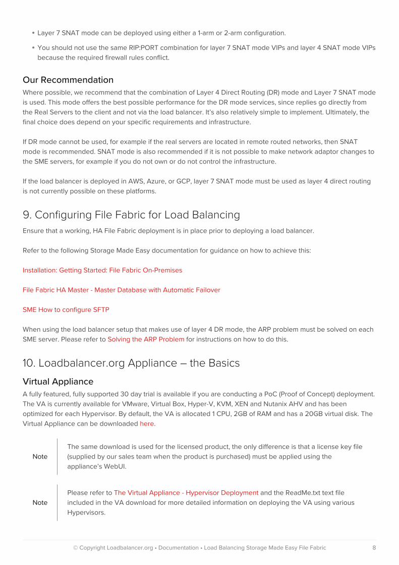
Our Recommendation
Where possible, we recommend that the combination of Layer 4 Direct Routing (DR) mode and Layer 7 SNAT mode
is used. This mode offers the best possible performance for the DR mode services, since replies go directly from
the Real Servers to the client and not via the load balancer. It’s also relatively simple to implement. Ultimately, the
final choice does depend on your specific requirements and infrastructure.
If DR mode cannot be used, for example if the real servers are located in remote routed networks, then SNAT
mode is recommended. SNAT mode is also recommended if it is not possible to make network adaptor changes to
the SME servers, for example if you do not own or do not control the infrastructure.
If the load balancer is deployed in AWS, Azure, or GCP, layer 7 SNAT mode must be used as layer 4 direct routing
is not currently possible on these platforms.
9. Configuring File Fabric for Load Balancing
Ensure that a working, HA File Fabric deployment is in place prior to deploying a load balancer.
Refer to the following Storage Made Easy documentation for guidance on how to achieve this:
Installation: Getting Started: File Fabric On-Premises
File Fabric HA Master - Master Database with Automatic Failover
SME How to configure SFTP
When using the load balancer setup that makes use of layer 4 DR mode, the ARP problem must be solved on each
SME server. Please refer to Solving the ARP Problem for instructions on how to do this.
10. Loadbalancer.org Appliance – the Basics
Virtual Appliance
A fully featured, fully supported 30 day trial is available if you are conducting a PoC (Proof of Concept) deployment.
The VA is currently available for VMware, Virtual Box, Hyper-V, KVM, XEN and Nutanix AHV and has been
optimized for each Hypervisor. By default, the VA is allocated 1 CPU, 2GB of RAM and has a 20GB virtual disk. The
Virtual Appliance can be downloaded here.
Note
The same download is used for the licensed product, the only difference is that a license key file
(supplied by our sales team when the product is purchased) must be applied using the
appliance’s WebUI.
Note
Please refer to The Virtual Appliance - Hypervisor Deployment and the ReadMe.txt text file
included in the VA download for more detailed information on deploying the VA using various
Hypervisors.
© Copyright Loadbalancer.org • Documentation • Load Balancing Storage Made Easy File Fabric 8

Note
For the VA, 4 NICs are included but only eth0 is connected by default at power up. If the other
NICs are required, these should be connected using the network configuration screen within the
Hypervisor.
Initial Network Configuration
After boot up, follow the instructions on the console to configure the IP address, subnet mask, default gateway,
DNS and other network settings.
ImportantBe sure to set a secure password for the load balancer, when prompted during the setup
routine.
Accessing the WebUI
The WebUI is accessed using a web browser. Appliance authentication is based on Apache .htaccess files. User
admin tasks such as adding users and changing passwords can be performed using the WebUI menu option:
Maintenance > Passwords.
NoteA number of compatibility issues have been found with various versions of Internet Explorer and
Edge. The WebUI has been tested and verified using both Chrome & Firefox.
NoteIf required, users can also be authenticated against LDAP, LDAPS, Active Directory or Radius. For
more information please refer to External Authentication.
1. Using a browser, access the WebUI using the following URL:
https://<IP-address-configured-during-network-setup-wizard>:9443/lbadmin/
2. Log in to the WebUI:
Username: loadbalancer
Password: <configured-during-network-setup-wizard>
Note To change the password, use the WebUI menu option: Maintenance > Passwords.
Once logged in, the WebUI will be displayed as shown below:
© Copyright Loadbalancer.org • Documentation • Load Balancing Storage Made Easy File Fabric 9

NoteThe WebUI for the VA is shown, the hardware and cloud appliances are very similar. The
yellow licensing related message is platform & model dependent.
3. You’ll be asked if you want to run the Setup Wizard. If you click Accept the Layer 7 Virtual Service
configuration wizard will start. If you want to configure the appliance manually, simple click Dismiss.
Main Menu Options
System Overview - Displays a graphical summary of all VIPs, RIPs and key appliance statistics
Local Configuration - Configure local host settings such as IP address, DNS, system time etc.
Cluster Configuration - Configure load balanced services such as VIPs & RIPs
Maintenance - Perform maintenance tasks such as service restarts and taking backups
View Configuration - Display the saved appliance configuration settings
Reports - View various appliance reports & graphs
© Copyright Loadbalancer.org • Documentation • Load Balancing Storage Made Easy File Fabric 10

Logs - View various appliance logs
Support - Create a support download, contact the support team & access useful links
Live Chat - Start a Live Chat session with one of our Support Engineers
HA Clustered Pair Configuration
Loadbalancer.org recommend that load balancer appliances are deployed in pairs for high availability. In this guide
a single unit is deployed first, adding a secondary unit is covered in Configuring HA - Adding a Secondary
Appliance.
11. Appliance Configuration for File Fabric – Using Layer 4 DR Mode and
Layer 7 SNAT Mode
Duplicate Service Function
As of version 8.3.8 of the Loadbalancer.org appliance, the Duplicate Service button can be used to save time
during initial configuration. This function duplicates the configuration of a given virtual service along with all of the
associated back end real servers which have been defined. This is useful for deployments where multiple, very
similar virtual services are used, with only minor changes between them. It saves time as the same settings and real
servers do not need to be repeatedly defined.
First, fully create the initial virtual service as directed. Then click the Modify button for the virtual service in
question, click the Duplicate Service button near the top, and make the necessary changes for the new, duplicated
virtual service.
This feature is available for both layer 4 and layer 7 virtual services.
Layer 4 Direct Routing Configuration
Configuring VIP 1 – SME Web Portal
Configuring the Virtual Service (VIP)
1. Using the web user interface, navigate to Cluster Configuration > Layer 4 – Virtual Services and click on Add a
new Virtual Service.
2. Define the Label for the virtual service as required, e.g. SME_WebPortal.
3. Set the Virtual Service IP Address field to the required IP address, e.g. 192.168.86.84.
4. Set the Ports field to 80,443.
5. Leave the Protocol set to TCP.
6. Leave the Forwarding Method set to Direct Routing.
7. Click Update to create the virtual service.
© Copyright Loadbalancer.org • Documentation • Load Balancing Storage Made Easy File Fabric 11

8. Click Modify next to the newly created VIP.
9. Ensure that the Persistence Enable checkbox is checked and that the Timeout is set to 1800.
10. Leave the Health Checks Check Type set to Connect to port.
11. Click Update.
Defining the Real Servers (RIPs)
1. Using the web user interface, navigate to Cluster Configuration > Layer 4 – Real Servers and click on Add a
new Real Server next to the newly created VIP.
2. Define the Label for the real server as required, e.g. SMEWEB01.
3. Set the Real Server IP Address field to the required IP address, e.g. 192.168.86.78.
4. Click Update.
5. Repeat these steps to add additional SME servers as required.
© Copyright Loadbalancer.org • Documentation • Load Balancing Storage Made Easy File Fabric 12

Configuring VIP 2 – SME SFTP
Configuring the Virtual Service (VIP)
1. Using the web user interface, navigate to Cluster Configuration > Layer 4 – Virtual Services and click on Add a
new Virtual Service.
2. Define the Label for the virtual service as required, e.g. SME_SFTP.
3. Set the Virtual Service IP Address field to the required IP address, e.g. 192.168.86.84.
4. Set the Ports field to 2200.
5. Leave the Protocol set to TCP.
6. Leave the Forwarding Method set to Direct Routing.
7. Click Update to create the virtual service.
8. Click Modify next to the newly created VIP.
9. Ensure that the Persistence Enable checkbox is checked and that the Timeout is set to 1800.
© Copyright Loadbalancer.org • Documentation • Load Balancing Storage Made Easy File Fabric 13

10. Leave the Health Checks Check Type set to Connect to port.
11. Click Update.
Defining the Real Servers (RIPs)
1. Using the web user interface, navigate to Cluster Configuration > Layer 4 – Real Servers and click on Add a
new Real Server next to the newly created VIP.
2. Define the Label for the real server as required, e.g. SMEWEB01.
3. Set the Real Server IP Address field to the required IP address, e.g. 192.168.86.78.
4. Click Update.
5. Repeat these steps to add additional SME servers as required.
Layer 7 SNAT Mode Configuration
To load balance the SQL and Memcache services, layer 7 virtual services should be used. This is because layer 4
direct routing mode does not provide any real benefit or advantage for these services.
To set up layer 7 virtual services for SQL and Memcache, follow the appropriate instructions from the next section
of this document, Appliance Configuration for File Fabric – Using Only Layer 7 SNAT Mode, i.e.:
© Copyright Loadbalancer.org • Documentation • Load Balancing Storage Made Easy File Fabric 14

Configuring VIP 3 – SME SQL
Configuring VIP 4 – SME Memcache
Finalizing the Configuration
12. Appliance Configuration for File Fabric – Using Only Layer 7 SNAT
Mode
Duplicate Service Function
As of version 8.3.8 of the Loadbalancer.org appliance, the Duplicate Service button can be used to save time
during initial configuration. This function duplicates the configuration of a given virtual service along with all of the
associated back end real servers which have been defined. This is useful for deployments where multiple, very
similar virtual services are used, with only minor changes between them. It saves time as the same settings and real
servers do not need to be repeatedly defined.
First, fully create the initial virtual service as directed. Then click the Modify button for the virtual service in
question, click the Duplicate Service button near the top, and make the necessary changes for the new, duplicated
virtual service.
This feature is available for both layer 4 and layer 7 virtual services.
Configuring VIP 1 – SME Web Portal
Configuring the Virtual Service (VIP)
1. Using the web user interface, navigate to Cluster Configuration > Layer 7 – Virtual Services and click on Add a
new Virtual Service.
2. Define the Label for the virtual service as required, e.g. SME_WebPortal.
3. Set the Virtual Service IP Address field to the required IP address, e.g. 192.168.86.84.
4. Set the Virtual Service Ports field to 80,443.
5. Set the Layer 7 Protocol to TCP Mode.
6. Click Update to create the virtual service.
© Copyright Loadbalancer.org • Documentation • Load Balancing Storage Made Easy File Fabric 15

7. Click Modify next to the newly created VIP.
8. Set Persistence Mode to Source IP.
9. Set Health Checks to Connect to port.
10. In the Other section click Advanced to expand the menu.
11. Check the Timeout checkbox.
12. Set Client Timeout to 5m (this is 5 minutes).
13. Set Real Server Timeout to 5m.
14. Click Update.
Defining the Real Servers (RIPs)
1. Using the web user interface, navigate to Cluster Configuration > Layer 7 – Real Servers and click on Add a
new Real Server next to the newly created VIP.
2. Enter an appropriate name for the server in the Label field, e.g. SMEWEB01.
3. Change the Real Server IP Address field to the required IP address, e.g. 192.168.86.78.
4. Click Update.
5. Repeat these steps to add additional servers as required.
© Copyright Loadbalancer.org • Documentation • Load Balancing Storage Made Easy File Fabric 16
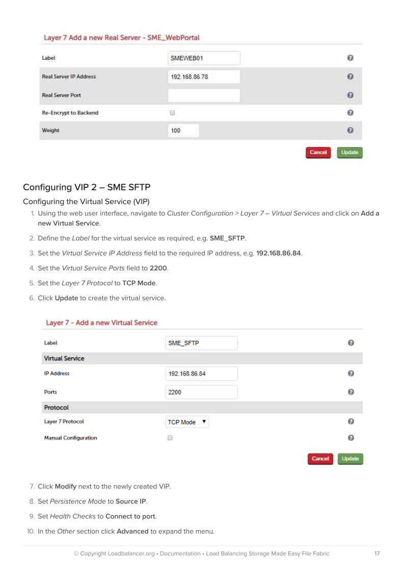
Configuring VIP 2 – SME SFTP
Configuring the Virtual Service (VIP)
1. Using the web user interface, navigate to Cluster Configuration > Layer 7 – Virtual Services and click on Add a
new Virtual Service.
2. Define the Label for the virtual service as required, e.g. SME_SFTP.
3. Set the Virtual Service IP Address field to the required IP address, e.g. 192.168.86.84.
4. Set the Virtual Service Ports field to 2200.
5. Set the Layer 7 Protocol to TCP Mode.
6. Click Update to create the virtual service.
7. Click Modify next to the newly created VIP.
8. Set Persistence Mode to Source IP.
9. Set Health Checks to Connect to port.
10. In the Other section click Advanced to expand the menu.
© Copyright Loadbalancer.org • Documentation • Load Balancing Storage Made Easy File Fabric 17
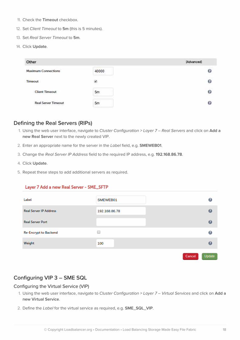
11. Check the Timeout checkbox.
12. Set Client Timeout to 5m (this is 5 minutes).
13. Set Real Server Timeout to 5m.
14. Click Update.
Defining the Real Servers (RIPs)
1. Using the web user interface, navigate to Cluster Configuration > Layer 7 – Real Servers and click on Add a
new Real Server next to the newly created VIP.
2. Enter an appropriate name for the server in the Label field, e.g. SMEWEB01.
3. Change the Real Server IP Address field to the required IP address, e.g. 192.168.86.78.
4. Click Update.
5. Repeat these steps to add additional servers as required.
Configuring VIP 3 – SME SQL
Configuring the Virtual Service (VIP)
1. Using the web user interface, navigate to Cluster Configuration > Layer 7 – Virtual Services and click on Add a
new Virtual Service.
2. Define the Label for the virtual service as required, e.g. SME_SQL_VIP.
© Copyright Loadbalancer.org • Documentation • Load Balancing Storage Made Easy File Fabric 18

3. Set the Virtual Service IP Address field to the required IP address, e.g. 192.168.86.81.
4. Set the Virtual Service Ports field to 3306.
5. Set the Layer 7 Protocol to TCP Mode.
6. Click Update to create the virtual service.
7. Click Modify next to the newly created VIP.
8. Set Persistence Mode to Source IP.
9. Set Health Checks to Connect to port.
10. In the Other section click Advanced to expand the menu.
11. Check the Timeout checkbox.
12. Set Client Timeout to 5m (this is 5 minutes).
13. Set Real Server Timeout to 5m.
14. Click Update.
Defining the Real Servers (RIPs)
1. Using the web user interface, navigate to Cluster Configuration > Layer 7 – Real Servers and click on Add a
new Real Server next to the newly created VIP.
© Copyright Loadbalancer.org • Documentation • Load Balancing Storage Made Easy File Fabric 19

2. Enter an appropriate name for the server in the Label field, e.g. SMESQL01.
3. Change the Real Server IP Address field to the required IP address, e.g. 192.168.86.82.
4. Click Update.
5. Repeat these steps to add additional servers as required.
Configuring VIP 4 – SME Memcache
Configuring the Virtual Service (VIP)
1. Using the web user interface, navigate to Cluster Configuration > Layer 7 – Virtual Services and click on Add a
new Virtual Service.
2. Define the Label for the virtual service as required, e.g. SME_MEMCACHE_VIP.
3. Set the Virtual Service IP Address field to the required IP address, e.g. 192.168.86.86.
4. Set the Virtual Service Ports field to 11211.
5. Set the Layer 7 Protocol to TCP Mode.
6. Click Update to create the virtual service.
© Copyright Loadbalancer.org • Documentation • Load Balancing Storage Made Easy File Fabric 20

7. Click Modify next to the newly created VIP.
8. Set Persistence Mode to Source IP.
9. Set Health Checks to Connect to port.
10. In the Other section click Advanced to expand the menu.
11. Check the Timeout checkbox.
12. Set Client Timeout to 5m (this is 5 minutes).
13. Set Real Server Timeout to 5m.
14. Click Update.
Defining the Real Servers (RIPs)
1. Using the web user interface, navigate to Cluster Configuration > Layer 7 – Real Servers and click on Add a
new Real Server next to the newly created VIP.
2. Enter an appropriate name for the server in the Label field, e.g. SMESQL01.
3. Change the Real Server IP Address field to the required IP address, e.g. 192.168.86.82.
4. Click Update.
5. Repeat these steps to add additional servers as required.
© Copyright Loadbalancer.org • Documentation • Load Balancing Storage Made Easy File Fabric 21
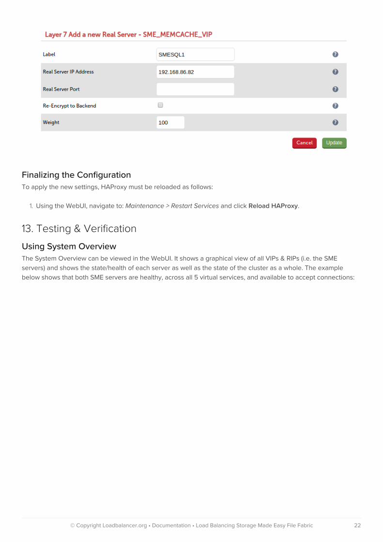
Finalizing the Configuration
To apply the new settings, HAProxy must be reloaded as follows:
1. Using the WebUI, navigate to: Maintenance > Restart Services and click Reload HAProxy.
13. Testing & Verification
Using System Overview
The System Overview can be viewed in the WebUI. It shows a graphical view of all VIPs & RIPs (i.e. the SME
servers) and shows the state/health of each server as well as the state of the cluster as a whole. The example
below shows that both SME servers are healthy, across all 5 virtual services, and available to accept connections:
© Copyright Loadbalancer.org • Documentation • Load Balancing Storage Made Easy File Fabric 22

Layer 4 Direct Routing Specific Check
If using the setup that combines layer 4 DR mode and layer 7 SNAT mode, it is possible to specifically check that
layer 4 DR mode has been correctly configured (including verifying that the real servers have been modified
correctly in regards to the ARP problem).
After sending traffic to the layer 4 DR mode virtual services, check that connections are not in the SYN_RECV state
and that they are ESTABLISHED. This can be done through the load balancer’s WebUI, by navigating to Reports >
Layer 4 Current Connections.
If there are a significant number of connections in the SYN_RECV state then that implies that the ARP problem has
not been correctly resolved on the back end real servers.
© Copyright Loadbalancer.org • Documentation • Load Balancing Storage Made Easy File Fabric 23

SFTP Service Check
For details on how to perform a check of the SFTP service, see Testing the SFTP Service.
14. Technical Support
For more details about configuring the appliance and assistance with designing your deployment please don’t
hesitate to contact the support team using the following email address: [email protected].
15. Further Documentation
The Administration Manual contains much more information about configuring and deploying the appliance. It’s
available here: https://pdfs.loadbalancer.org/loadbalanceradministrationv8.pdf.
16. Conclusion
Loadbalancer.org appliances provide a very cost effective solution for highly available load balanced Storage Made
Easy File Fabric environments.
© Copyright Loadbalancer.org • Documentation • Load Balancing Storage Made Easy File Fabric 24

17. Appendix
Solving the ARP Problem
When using Layer 4 DR mode, the ARP problem must be solved. This involves configuring each Real Server to be
able to receive traffic destined for the VIP, and ensuring that each Real Server does not respond to ARP requests
for the VIP address – only the load balancer should do this. The steps below are for Windows 2012 and later.
Windows Server 2012, 2016 & 2019
The basic concept is the same as for Windows 2000/2003. However, additional steps are required to set the
strong/weak host behavior. This is used to either block or allow interfaces receiving packets destined for a different
interface on the same server. As with Windows 2000/2003/2008, if the Real Server is included in multiple VIPs,
you can add additional IP addresses to the Loopback Adapter that correspond to each VIP.
Step 1 of 3: Install the Microsoft Loopback Adapter
1. Click Start, then run hdwwiz to start the Hardware Installation Wizard.
2. When the Wizard has started, click Next.
3. Select Install the hardware that I manually select from a list (Advanced), click Next.
4. Select Network adapters, click Next.
5. Select Microsoft & Microsoft KM-Test Loopback Adapter, click Next.
6. Click Next to start the installation, when complete click Finish.
Step 2 of 3: Configure the Loopback Adapter
1. Open Control Panel and click Network and Sharing Center.
2. Click Change adapter settings.
© Copyright Loadbalancer.org • Documentation • Load Balancing Storage Made Easy File Fabric 25

3. Right-click the new Loopback Adapter and select Properties.
4. Uncheck all items except Internet Protocol Version 4 (TCP/IPv4) and Internet Protocol Version 6 (TCP/IPv6)
as shown below:
NoteLeaving both checked ensures that both IPv4 and IPv6 are supported. Select one If
preferred.
5. If configuring IPv4 addresses select Internet Protocol Version (TCP/IPv4), click Properties and configure the IP
address to be the same as the Virtual Service (VIP) with a subnet mask of 255.255.255.255 , e.g.
192.168.2.20/255.255.255.255 as shown below:
© Copyright Loadbalancer.org • Documentation • Load Balancing Storage Made Easy File Fabric 26
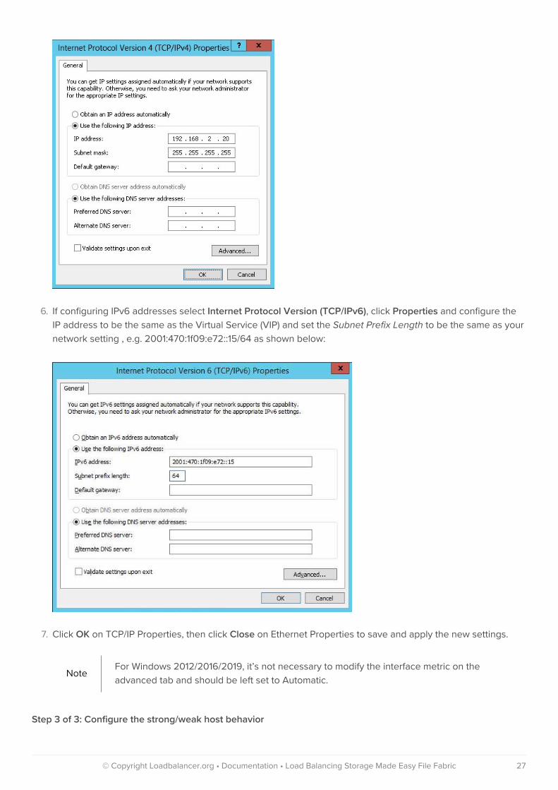
6. If configuring IPv6 addresses select Internet Protocol Version (TCP/IPv6), click Properties and configure the
IP address to be the same as the Virtual Service (VIP) and set the Subnet Prefix Length to be the same as your
network setting , e.g. 2001:470:1f09:e72::15/64 as shown below:
7. Click OK on TCP/IP Properties, then click Close on Ethernet Properties to save and apply the new settings.
NoteFor Windows 2012/2016/2019, it’s not necessary to modify the interface metric on the
advanced tab and should be left set to Automatic.
Step 3 of 3: Configure the strong/weak host behavior
© Copyright Loadbalancer.org • Documentation • Load Balancing Storage Made Easy File Fabric 27

To configure the correct strong/weak host behavior for Windows 2012/2016/2019, the following commands must be
run on each Real Server:
For IPv4 addresses:
netsh interface ipv4 set interface "net" weakhostreceive=enablednetsh interface ipv4 set interface "loopback" weakhostreceive=enablednetsh interface ipv4 set interface "loopback" weakhostsend=enabled
For these commands to work, the LAN connection NIC must be named "net" and the loopback NIC must be named
"loopback" as shown below. If you prefer to leave your current NIC names, then the commands above must be
modified accordingly. For example, if your network adapters are named "LAN" and "LOOPBACK", the commands
required would be:
netsh interface ipv4 set interface "LAN" weakhostreceive=enablednetsh interface ipv4 set interface "LOOPBACK" weakhostreceive=enablednetsh interface ipv4 set interface "LOOPBACK" weakhostsend=enabled
For IPv6 addresses:
netsh interface ipv6 set interface "net" weakhostreceive=enablednetsh interface ipv6 set interface "loopback" weakhostreceive=enablednetsh interface ipv6 set interface "loopback" weakhostsend=enablednetsh interface ipv6 set interface "loopback" dadtransmits=0
For these commands to work, the LAN connection NIC must be named "net" and the loopback NIC must be named
"loopback" as shown below. If you prefer to leave your current NIC names, then the commands above must be
modified accordingly. For example, if your network adapters are named "LAN" and "LOOPBACK", the commands
required would be:
netsh interface ipv6 set interface "LAN" weakhostreceive=enablednetsh interface ipv6 set interface "LOOPBACK" weakhostreceive=enablednetsh interface ipv6 set interface "LOOPBACK" weakhostsend=enablednetsh interface ipv6 set interface "LOOPBACK" dadtransmits=0
NoteThe names for the NICs are case sensitive, so make sure that the name used for the interface and
the name used in the commands match exactly.
Start PowerShell or use a command window to run the appropriate netsh commands as shown in the example
below:
© Copyright Loadbalancer.org • Documentation • Load Balancing Storage Made Easy File Fabric 28
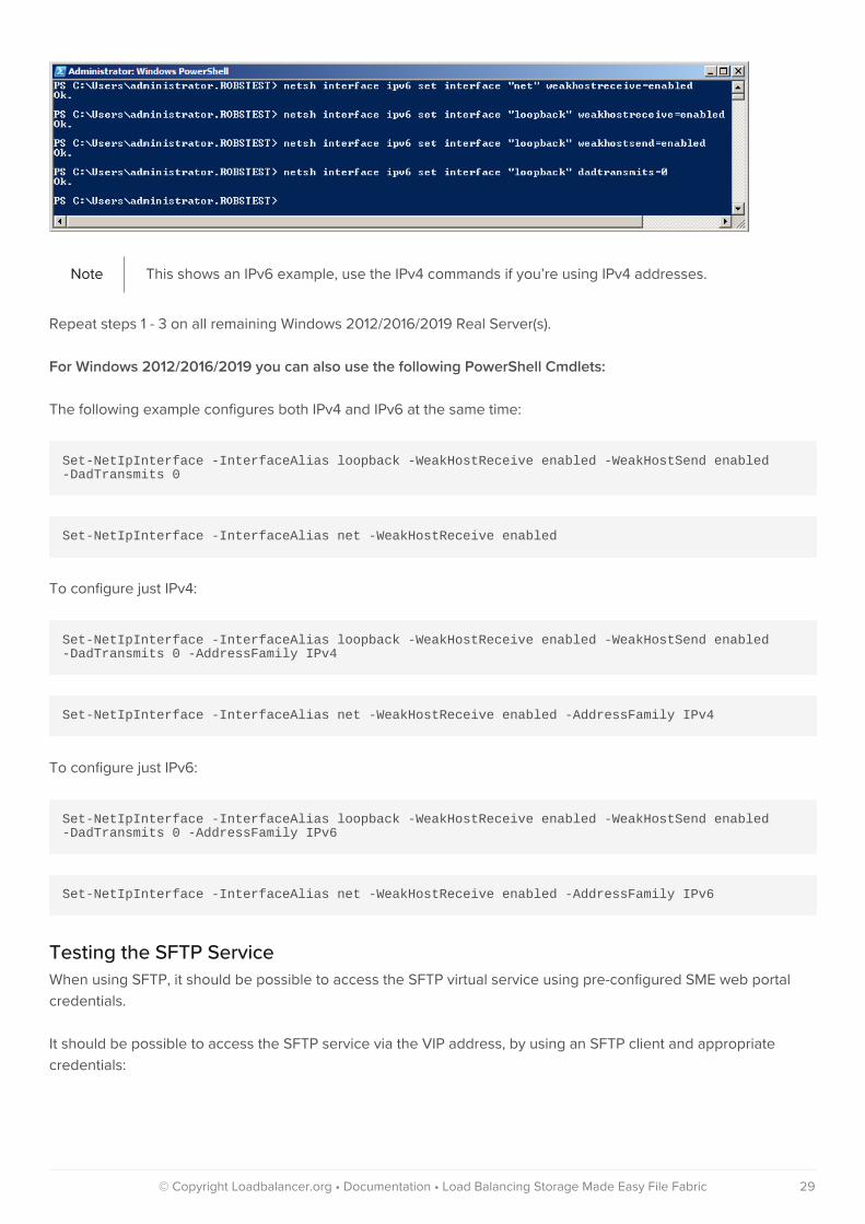
Note This shows an IPv6 example, use the IPv4 commands if you’re using IPv4 addresses.
Repeat steps 1 - 3 on all remaining Windows 2012/2016/2019 Real Server(s).
For Windows 2012/2016/2019 you can also use the following PowerShell Cmdlets:
The following example configures both IPv4 and IPv6 at the same time:
Set-NetIpInterface -InterfaceAlias loopback -WeakHostReceive enabled -WeakHostSend enabled-DadTransmits 0
Set-NetIpInterface -InterfaceAlias net -WeakHostReceive enabled
To configure just IPv4:
Set-NetIpInterface -InterfaceAlias loopback -WeakHostReceive enabled -WeakHostSend enabled-DadTransmits 0 -AddressFamily IPv4
Set-NetIpInterface -InterfaceAlias net -WeakHostReceive enabled -AddressFamily IPv4
To configure just IPv6:
Set-NetIpInterface -InterfaceAlias loopback -WeakHostReceive enabled -WeakHostSend enabled-DadTransmits 0 -AddressFamily IPv6
Set-NetIpInterface -InterfaceAlias net -WeakHostReceive enabled -AddressFamily IPv6
Testing the SFTP Service
When using SFTP, it should be possible to access the SFTP virtual service using pre-configured SME web portal
credentials.
It should be possible to access the SFTP service via the VIP address, by using an SFTP client and appropriate
credentials:
© Copyright Loadbalancer.org • Documentation • Load Balancing Storage Made Easy File Fabric 29

The test connection should appear on the System Overview page:
Configuring HA - Adding a Secondary Appliance
Our recommended configuration is to use a clustered HA pair of load balancers to provide a highly available and
resilient load balancing solution.
We recommend that the Primary appliance should be configured first, then the Secondary should be added. Once
the Primary and Secondary are paired, all load balanced services configured on the Primary are automatically
replicated to the Secondary over the network using SSH/SCP.
© Copyright Loadbalancer.org • Documentation • Load Balancing Storage Made Easy File Fabric 30

Note
For Enterprise Azure, the HA pair should be configured first. In Azure, when creating a VIP using
an HA pair, 2 private IPs must be specified – one for the VIP when it’s active on the Primary and
one for the VIP when it’s active on the Secondary. Configuring the HA pair first, enables both IPs
to be specified when the VIP is created.
The clustered HA pair uses Heartbeat to determine the state of the other appliance. Should the active device
(normally the Primary) suffer a failure, the passive device (normally the Secondary) will take over.
Note
A number of settings are not replicated as part of the Primary/Secondary pairing process and
therefore must be manually configured on the Secondary appliance. These are listed by WebUI
menu option in the table below:
WebUI Main Menu
Option
Sub Menu Option Description
Local Configuration Hostname & DNS Hostname and DNS settings
Local Configuration Network Interface
Configuration
All network settings including IP address(es), bonding configuration
and VLANs
Local Configuration Routing Routing configuration including default gateways and static routes
Local Configuration System Date & time All time and date related settings
Local Configuration Physical – Advanced
Configuration
Various settings including Internet Proxy, Management Gateway,
Firewall connection tracking table size, NIC offloading, SMTP relay,
logging and Syslog Server
Local Configuration Security Appliance security settings
Local Configuration SNMP Configuration Appliance SNMP settings
Local Configuration Graphing Appliance graphing settings
Local Configuration License Key Appliance licensing
Maintenance Software Updates Appliance software update management
Maintenance Firewall Script Appliance firewall (iptables) configuration
Maintenance Firewall Lockdown
Wizard
Appliance management lockdown settings
To add a Secondary node - i.e. create a highly available clustered pair:
1. Deploy a second appliance that will be the Secondary and configure initial network settings.
2. Using the WebUI, navigate to: Cluster Configuration > High-Availability Configuration.
© Copyright Loadbalancer.org • Documentation • Load Balancing Storage Made Easy File Fabric 31

3. Specify the IP address and the loadbalancer user’s password for the Secondary (peer) appliance as shown
above.
4. Click Add new node.
5. The pairing process now commences as shown below:
6. Once complete, the following will be displayed:
7. To finalize the configuration, restart heartbeat and any other services as prompted in the blue message box at
the top of the screen.
© Copyright Loadbalancer.org • Documentation • Load Balancing Storage Made Easy File Fabric 32

NoteClicking the Restart Heartbeat button on the Primary appliance will also automatically restart
heartbeat on the Secondary appliance.
NoteFor more details on configuring HA with 2 appliances, please refer to Appliance Clustering for
HA.
© Copyright Loadbalancer.org • Documentation • Load Balancing Storage Made Easy File Fabric 33

18. Document Revision History
Version Date Change Reason for Change Changed By
1.0.0 17 December 2019 Initial version IBG, AH
1.0.1 3 September 2020 New title page
Updated Canadian contact details
Branding update
Change to Canadian
contact details
AH
1.1.0 1 December 2021 Converted the document to AsciiDoc Move to new
documentation
system
AH, RJC, ZAC
© Copyright Loadbalancer.org • Documentation • Load Balancing Storage Made Easy File Fabric 34

About Loadbalancer.orgLoadbalancer.org’s mission is to ensure that its clients’ businesses are never interrupted. The load balancer experts ask the right questions to get to the heart of what matters, bringing a depth of understanding to each deployment. Experience enables Loadbalancer.org engineers to design less complex, unbreakable solutions - andto provide exceptional personalized support.
United Kingdom
Loadbalancer.org Ltd.Compass House, North HarbourBusiness Park, Portsmouth, PO6 4PSUK:+44 (0) 330 380 [email protected]@loadbalancer.org
Canada
Loadbalancer.org Appliances Ltd.300-422 Richards Street, Vancouver,BC, V6B 2Z4, CanadaTEL:+1 866 998 [email protected]@loadbalancer.org
United States
Loadbalancer.org, Inc.4550 Linden Hill Road, Suite 201Wilmington, DE 19808, USATEL: +1 [email protected]@loadbalancer.org
Germany
Loadbalancer.org GmbHTengstraße 2780798,München, GermanyTEL: +49 (0)89 2000 [email protected]@loadbalancer.org
© Copyright Loadbalancer.org • www.loadbalancer.org