lnterpact Compact CM - ElectricalPartManuals.com Gerin... · Compact 1989 new products Here under,...
164
Compact lnterpact Compact CM e el power www . ElectricalPartManuals . com
Transcript of lnterpact Compact CM - ElectricalPartManuals.com Gerin... · Compact 1989 new products Here under,...

Compact lnterpact Compact CM
mastering electrical power www . El
ectric
alPar
tMan
uals
. com

------�-----�-�··�,.-·�-,-----------------------------·
www . El
ectric
alPar
tMan
uals
. com

:---115--
t 155 J
.,.,1'-1/lr
www . El
ectric
alPar
tMan
uals
. com

www . El
ectric
alPar
tMan
uals
. com

Compact 1989 new products
Here under, briefly, the most significant innovations. In order to obtain all relevant technical informations, look into your 89 low voltage catalogue.
Compact C1 01 N/H/L The new Compact C101 N/H/L circuitbreaker offers reduced dimensions in a 100 ampere size frame. Thanks to its exceptional connection by bars, crimped lugs and cables without additional accessories.
Compact C401 N/H/L The new Compact C401 N/H/L circuitbreaker replaces the actual C400N/H/L equipped with the standard trip units. The C401 N/H/L offers new motor protection trip units with adjustable magnetic and new direct current trip units.
lnterpact IN switches A range from 63 to 2500 A with high performances : • high making capacity, • long mechanical life, • positive break indication, • 3 pole width for the ratings 1000 up to 2500 A.
Panelpact Panelpact is a new mccb's distribution board which can be erected at any public place.
Visucompact CSOON ST to C1250N ST Fully visible break up to mccb's 1250 A. The visual proof of isolation between supply and load circuits can be achieved by : • fixed Visucompact C161N to C1250N ST, • drawout Visucompact CBOON ST to C1250N ST.
New performances for mccb's C161N/H/L • the C161N/H/L is now available for the ratings 100 and 125 A.
See pages 1 00 to 1 03.
See pages 64 to 66.
www . El
ectric
alPar
tMan
uals
. com

Compact system
page N° description characteristics
arts numbers C100E C225E C400E C600E C100NF F150N C101N/H/L C161N/H/L TC160N/L C250N/H/L C401N/H/L C630N/H/L C400N/H/L ST C630N/H/L ST C800N/H/L ST C1000N/H/L ST
Compact circuit-breakers with thermal-magnetic trip units
circuit protection and control
c:9 D type
protection with low magnetic threshold
t:9 G type
selectivity for protection against short-circuit
(9 SA, SB type
protection of motor starters
c:9 MA type
6 8 8 8 10 19 26 26 26 26
58 58 58 58 58 58 60 60 61 61 61 64 64 66 66 66 68 68 6B 68 70 70 70 70 74 74 74 80 80 80
Compact circuit-breakers with control units (solid state trip units)
circuit protection and control
l5? ST204S, ST2050, ST305G
selectivity for protection against short-circuits
� ST204S, ST305S, ST305SL, ST204SB, ST305SB
9 9 9 20 30 30
76 82 86 86 86 88 88 88 an QO 90
models and add-ons
residual current protection
with Vigi module : Vigicompact(1)
fully visible break
with Visu module: Visui::ompact
11 1 2 32
61 65 69 71 7 2 75 7 8 81 8 4 77 7 8 83 8 4 86 9 2 86 92 86 9'2
auxiliaries and accessories
-electrical auxiliaries
(j remote control
� accessories
� connection
14 13 14 14 40 41 50 54
59 59 59 59 59 59 59 59 59 59 59
59 59
63 63 63 67 67 67 69 69 69 69 73 73 73 73 79 79 79 79 85 85 85 85 79 79 79 79 85 85 85 85 87 87 87 87 89 89 89 89 91 91 91 91
www . El
ectric
alPar
tMan
uals
. com

source changeover
automatic and manual soi.Jrce changeover
13 42
94 94 94 94 94 94 94 94
l nterpact load break switches Compact Nl load break switches Fupact fuse-switches
lnterpact load break switches
auxiliaries and accessories
electrical auxiliaries
accessories
connection
98 99 100 102 103
Compact type Nl load break switches
10 104 105
auxiliaries and accessories
remote control
conneetion
63 67
73 79 85
87
91
Fupact fuse-switches
Compact CM
Compact CM with control units (solid state trip units)
circuit protection and control
STCM1
selectivity for protection against short-circuit
STCM2 STCM3
144 145 145 148 148 148 154
auxiliaries and accessories
electrical auxiliaries
remote control
connection
144 144 150 153 155 155
www . El
ectric
alPar
tMan
uals
. com

www . El
ectric
alPar
tMan
uals
. com

low voltage mccb's Compact 11 to 1250 A
1 Compact system
___________ page
presentation 6 Compact type D, G, SA, SB 8 Compact type ST 9 Compact type MA, Nl 10 Vigicompact 11 Compact with Vigirex
withdrawable Compact 12 Visucompact remote control 13 automatic source changeover auxiliaries 14 accessories Compact circuit-breakers 15 UL listed
www . El
ectric
alPar
tMan
uals
. com

Compact system presentation
Compact t01 Compact C161
12
Compact C250 Compact C401 and C630
2 8
Compact C400 ST and C630 ST
Compact CBOO ST, C 1 000 ST and C1 250 ST
7
1 basic frame 2 release unit interchangeable 3 Vigi module for earth leakage
protection up to C630N/H/L 4 Visu module for fully visible break on
Compact or earth leakage Vigicompact 5 Shunt trip or undervoltage release
for remote tripping of the circuit breaker
6 auxiliary and alarm switches for signalling and control
7 motor mechanism for remote operation of the circuit breaker
8 rotary handle, breaker mounted, padlockable as standard, center lock optional
9 rotary handle type MCC 10 rotary handle without door locking 1 1 plug-in base 1 2 terminal shields, convertible to lug
shields
www . El
ectric
alPar
tMan
uals
. com

standards Merl in Gerin low voltage devices comply with all national and international standards (see table below) . The breaking capacities for 220 V, 380/415 V, 440 V, 500 V and 660 V given in this catalogue cover almost all existing three phase systems. Values for commonly used North American voltages are also given.
country
Europe France Germany Great Britain Australia Italy South Africa Finland
description
standard
IEC 157-1 NF C 63-120 VDE 0660 BS 4752 AS 2184 CEI 1 7.5 SASS 1 56 Fl E13
Compact moulded case circuit-breakers come in single-pole, two-pole, three-pole and four-pole versions. Available in fixed or drawout patterns, they are designed for the control and protection of electric circuits. Compact circuit-breakers are equipped with trip units providing: • protection against overloads by adjustable thermal releases or solid state trip units (control units); • protection against short-circuits by adjustable magnetic releases or solid state trip units (control units) (fixed threshold for C1 01 and C161 N/H/L). 4 levels of performances Compact circuit-breakers can meet 4 levels of performances: • Compact E type (economical); • Compact N type (standard) ; • Compact H type different from the standard Compact by its high breaking capacity; • current limiter Compact L type with a very high breaking capacity, (see table below).
kA
150
Moreover, the Compact and their derived breakers are approved for marine applications. Approvals for merchant marine and offshore (see page 1 8) . Specific regulation must be observed in order to reduce to minimum the risks involved in shipboard operations. The Compact circuit-breakers manufactured by Merlin Gerin are recognised by the following authorities: • Bureau Veritas: BV • Lloyd's Register of Shipping: LAS • Registro Italiano Navale: RINA • Germanische Lloyd's: GL • USSR Register of Shipping: USSR AS • Det Norske Veritas: JNV • American Bureau of Shipping: ASS
Modular design Compact circuit-breakers and switches are designed as modular, easy-to-fit, bolt-on, screw-on or clip-in units for simple design and layout of electrical installations and easy modifications. The shunt trip or undervoltage release, and the auxiliary and alarm switches are fitted inside the breaker avoiding all risk of contact with live parts on all the Compact range.
Positive break indication All Compact circuit-breakers ensure positive break indication. That means that the operating handle position reflects the position of the contacts and when the circuit breaker is in off position that all the fixed and moving contacts are separated by the required distance.
standards and description
Characteristics Dimensions, tripping curves Part numbers
page 1 7 page 11 3 page 57
Two other versions of the Compact range described in separate leaflets are: • UL listed according to UL 489, (see page 1 5) • designed to Japanese Industrial standard JIS C8370
Tropicalization Compact and Compact derived breakers as well as their auxiliaries are tropicalized. They meet treatment 2 requirements NF C 63-100 standards. Rate of relative humidity is 95 % at 45 %, or 80 % at 55 °C (warm and humid climate) .
Degree of protection (standard NF C 20-01 0) installation and type C101 NIHIL to of operating C1250N/H switchgear with terminal shields visible handle IP403 switchgear in enclosures or cubicles visible handle IP405 direct rotary handle IP405 extended rotary handle IP557 motor mechanism IP405
C401L C400LST
C630L C630L ST
ST C1000L ST
ST C1000H ST
CBOON ST OOON ST
www . El
ectric
alPar
tMan
uals
. com

Compact system presentation (continued)
Compact without release type trip unit
--
Complete circuit-breaker
circuit control and protection
low magnetic threshold protection
protection against shortcircuits w ith selectivity
protection against shortcircuits with SELLIM system selectivity
functions of Compact equipped with thermalmagnetic trip units
Characteristics Dimensions, tripping curbes Part numbers
Compact with standard D type trip unit
page 1 7 page 1 1 3 page 57
To ensure protection against overcurrents, Compact circuit-breakers are equipped with thermal-magnetic D type trip unit, interchangeable for TC160 to C630N/H/L (non interchangeable for C101 to C 1 61 N/H/L). This trip unit provides: • the protection against overloads by an adjustable thermal trip unit, • the protection against short-circuits by an adjustable magnetic trip for C250 to C630N/H/L (fixed threshold for C101 to C1 61 N/H/L)
Compact with G type trip unit Compact G type circuit-breakers come with G type thermal-magnetic trip units instead of the standard D type trip unit. They provide protection against overloads downstream of engine generator sets. G type trip unit interchangeable for TC1 60 to C630N/H/L (non interchangeable for C1 01 to C 1 61 N/H/L). This trip unit provides: • the protection against overloads by an adjustable thermal trip unit, • the protection against short-circuits by an adjustable magnetic trip for C250 to C630N/H/L (fixed threshold for C101 to C161 N/H/L) with a lower threshold than the D type trip unit.
Compact with SA type selective trip unit Compact SA type circuit-breakers come with SA type thermal-magnetic trip units instead of the standard D type trip unit. They improve protection selectivity on circuits subjected to heavy inrush currents (motor starting, no-load coupling of LV/LV transformers, etc.). The SA type trip unit is fitted on C 1 61 H/L, and interchangeable for TC1 60N/L and C250N/H/L. This trip unit provides: • the protection against overloads by an adjustable thermal trip unit, • the protection against short-circuits by a fixed threshold magnetic trip.
Compact with SB type selective trip unit Compact SB type circuit-breakers come with SB type thermal-magnetic trip units instead of the standard D type trip unit. They provide full selectivity with all downstream Compact circuit-breakers. The SB type trip unit is interchangeable for TC1 60L and C250L. This trip unit provides: • the protection against overloads by an adjustable thermal trip unit, • the protection against short-circuits by a fixed threshold magnetic trip
www . El
ectric
alPar
tMan
uals
. com

Compact C1 OOOL ST
Compact C630L ST
circuit control and protection
standard protection
short-time low threshold protection
protection against shortcircuits with selectivity
protection against short· circuits with SELLIM system selectivity
other functions
functions of Compact equipped with solid state trip units
Characteristics Dimensions, tripping curves Part numbers
Compact with control unit
page 30 page 1 1 3 page 57
The control unit is a solid state trip unit supplied by sensors built into the circuitbreaker. It operates on its own current and combines the protection features conventionally offered by the type D, G , SA and SB thermal-magnetic trip units. The control unit offers 3 levels of protection: • long time with adjustable setting for protection against overloads; • short time with adjustable pick-up and delay for protectjon against short-circuits; • instantaneous with fixed pick-up for protection against very high short-circuits.
Compact with control unit ST204S ou ST205D Depending on the Compact circuit-breaker type and rating, standard protection is provided by the following control units: • ST204S for Compact G400N/H/L ST and C630N/H/L ST; • ST2050 for Compact CSOON/H/L ST to C1 250N/H ST.
Compact with control unit ST305G Control unit ST305G is for Compact CSOON/H ST to C1250N/H ST circuitbreakers. It is specially designed for the protection of generators, long cables, etc. (high impedance circuits).
Compact with control unit ST204S, ST305S or ST305SL Depending on the Compact circuit-breaker type and rating, this protection is provided by the following control units: • ST204S for Compact C400N/H/L ST and C630N/H/L ST; • ST305S for Compact CSOON/H/L ST to C1 250N/H ST; • ST305SL for Compact CSOOL ST and C 1 000L ST. These control units provide short-circuit protection with time discrimination.
Compact with control unit ST204SB or ST305SB Depending on the Compact circuit-breaker type and rating, this protection is provided by the following control units: • ST204SB for Compact C400L ST and C630L ST; • ST305SB for Compact CSOOL ST and C1 000L ST. These control units are for Compact type L current limiting circuit-breakers. They combine the advantages of current l imiting and cascading, and provide full selectivity with all downstream Compact circuit-breakers.
Compact CSOON/H/L ST to C1250N/H ST circuit-breakers can be equipped with the following complementary functions: • ground fault protection (options T and Tz), • load monitoring and control (option A), - , ........ �--1!_ •• •
www . El
ectric
alPar
tMan
uals
. com

Compact system presentation (continued)
Compact without release MA type trip unit
--
Compact type MA
Compact CBOONI load break switch
starter protection
circuit control
Compact circuit-breaker for starter protection Compact load break switch
Characteristics Dimensions, tripping curves Part numbers
pages 1 7 and 1 0< page 1 1 3 pages 57 and 1 0!
Compact with MA type trip unit Compact MA type circuit-breakers offer magnetic protection only. The MA trip unit can be fitted on Compact C101 to C630N/H/L.
Protection of motors starters The starter, which consists of a contactor and a thermal relay, ensures remote control and protection against overloads. By protecting this starter by a Compact MA type circuit-breaker, the combination benefits from the functions and additional possibilities of the breaker: • control: in addition to the normal operating man03uvres, the Compact MA allows easy and safe on-load opening, particularly during starting, or in case of locking of the rotor. • protection against short-circuits: the Compact MA type circuit-breaker ensures the opening of all the poles with indication given by the position of the handle (OFF, ON, TRIPPED). • isolating: the Compact MA type circuitbreaker can be used to isolate circuits with positive break indication. • complementary functions: earth leakage protection, emergency tripping by shunt trip or undervoltage release, signalling by auxiliary contacts, etc.
Magnetic protection only Case of protection against short-circuits without the protection against overloads (LV/LV transformer).
Compact type Nl load break switches Compact type Nl load break switches are derived from Compact circuit-breakers, with the trip unit replaced by a type N l switch unit used to latch the operating mechanism. They provide positive break indication and may be used for applications such as: • coupling of two networks, • secondary switchboard input switch, • isolation of a motor from the network. Compact type Nl load break switches can be fitted with the same auxiliaries and accessories as Compact circuit-breakers: auxiliary switches, voltage releases, remote control systems, Vigi modules, locks, etc. The same functions can therefore be provided including: • residual current protection, • remote opening and closing, • manual or automatic source changeover.
www . El
ectric
alPar
tMan
uals
. com

Compact
--
Vigicompact
Compact C250N
+
Vigirex RH50
+
+ Vigi module
+ shunt trip release
. MX
residual current protection
residual current protection by an add-on module
residual current protection by a separate residual current relay
Vigicompact circuit-breaker Compact circuit-breaker with separate residual current relay
Characteristics Dimensions, tripping curves Part numbers
page 1 7
page 113
page 57
Residual current protection is used to provide several important functions: • protection of persons against direct contact (IT and TN grouding systems), • additional protection of persons against indirect contact (TT grouding systems), • protection of equipment and property against the risk of damage or fire caused by earth fault currents. The devices presented below are protected against inadvertent tripping.
Vigicompact The Vigicompact is made up of a Compact C1 01 N/H/L to C630N/H/L ST circuitbreaker with one of the following types of clip-in Vigi modules: • REH for the Vigicompact C101 N/H/L to C250N/H/L, • RMM for the Vigicompact C101 N/H/L and C161 N/H/L, • REM for the Vigicompact C401 N/H/L to C630N/H/L ST. The Vigi modules are interchangeable and may be fitted with lead seals.
Compact with Vigirex and separate toroid type sensor This type of residual current protection can be implemented on all Compact circuit-breakers from C1 01 N/H/L to C1 250N/H ST and on Compact type NJ load break switches. It consists of: • a Compact circuit-breaker or load break switch, • a voltage release, • a separate Vigirex residual current relay, • a separate toroid type sensor.
www . El
ectric
alPar
tMan
uals
. com

Compact system presentation (continued)
plug-in Compact and base
drawout chassis
Compact C1250N drawout version
+
Compact Visu module
--
withdrawability
fully visible break
withdrawable Compact Visucompact circuit breaker for the fully visible break
Characteristics Dimensions, tripping curves Part numbers
withdrawable Compacts The withdrawable function allows:
page 1 7 page 1 1 3 page 57
• removal of circuit-breaker without touching live parts, • fast interchanging of devices, • prewiring of extra fixed parts ready for easy fitting of the moving portion when additional outgoing circuits become necessary.
All withdrawable Compact circuit-breakers come with an automatic tripping device eliminating all danger of on-load withdrawal. The auxiliary circuits are disconnected at the same time as the power circuits.
Compact plug-in version with base Compact C101 N/H/L to C630N/H/L ST fixed circuit-breakers can be made withdrawable by adding a set of connecting pins and a plug-in base.
Compact with drawout chassis The drawout chassis is supplied as: • the standard withdrawable version for Compact C800N/H/L ST to C1 250N/H ST circuit-breakers, • a complementary version for Compact C 1 61 N/H/L to C630N/H/L ST plug-in circuit-breakers with base. Compact circuit-breakers on drawout chassis can be moved to three positions: • « connected » position with power and auxiliary circuits connected, • « disconnected » position with power and auxiliary circuits disconnected, • « fully withdrawn » position for checks requiring removal of the moving portion of the circuit-breaker from the chassis.
Visucompact Fully visible break, for all cases requiring visual proof of isolation between supply and load circuits for safety of persons, is provided by Visucompact circuit-breakers. These devices are available in fixed and drawout versions: • fixed Visucompact C1 61 N to C1250N ST comprising: o a fixed Compact circuit-breaker, o a Visu module which can be locked in « OFF » position by a padlock or keylock. The Visu module provides the fully visible break and allows on-load opening of the device. • drawout Visucompact C800N ST to C1 250N ST comprising: o a moving chassis as for the Compact circuit-breaker of the same rating, complete with an operating mechanism compartment and a handle extension. o a fixed part identical to that of the Compact of the same rating, complete with safety shutters blocking access to the power contacts and a « disconnected » ���"'"" n<>rllnr.kina device.
www . El
ectric
alPar
tMan
uals
. com

remote control
built-in remote control unit for Compact TC160N/L
+
Compact motor mechanism
--
motorised Compact
automatic source changeover
remote control automatic source changeover
Characteristics Dimensions, tripping curves Part numbers
page 1 7 page 1 1 3 page 57
The remote control comprises a unit which is fitted onto the front of the Compact circuit-breaker. This unit contains the electrical and mechanical parts which are able to actuate the circuit-breaker on remotely sent orders. This association enables the following to be performed: • remote opening and closing, • protection of circuits against overloads and short-circuits, • positive break indication, maintained with the remote control, and indicated by the position of the breaking devices.
This remote control can act: • on orders from push-buttons, switches or relays, • locally by action on the mechanical devices located on the front of the unit.
Compact TC1 60N/L The Compact TC1 60N/L is a Compact circuit-breaker equipped with a built-in remote control. It is mainly used for: • remote control and protection of distribution circuits (lighting, heating, air conditioning, overall control of a workshop, etc.); • special purposes such as general protection of installations accessible with difficulty (unit in weatherproof or explosion-proof enclosure, unit fitted outside dangerous or wet locations); • load shedding/restoring of non-priority circuits.
adaptable motor mechanism The adaptable motor mechanism is an add-on unit which can be easily fitted on the front of the Compact circuit-breaker. It is used for remote control of circuits with low operating frequencies.
The Compact C250N/H/L to C1250N/H can take 2 types of remote control: • the T type unit enabling: o daily opening and closing of a circuit from a control desk. o load shedding/restoring of non-priority circuits, o automatic source changeover. • the TS type unit which offers, in addition ot the functions of the T type, the possibility of performing high-speed closing synchrocoupling operations.
The automatic source changeovers of the Compact range are composed of: • a base plate; • 2 Compact (circuit-breakers or switch) rating 1 60 to 1 250 A with mechanical and electrical interlock. These breakers can be: o the same o different with respect to type rating or trip unit (see next page); • 2 type motor mechanism (1 per breaker); •
• an automatism plate in one single piece with terminal block for external connections.
www . El
ectric
alPar
tMan
uals
. com

Compact system presentation (continued)
2 OF block
CAM block
direct rotary handle
remote mdications remote tripping
front operation
instal lation
auxiliary switches, voltage releases, accessories
Characteristics Part numbers
auxiliary switches, voltage releases
page 17 page 57
A range of auxiliary contacts, shunt trips and undervoltage releases equips all Compact circuit-breakers and their derived products. These auxiliaries are fitted inside the circuit-breaker without any difficulty. Regarding particularly the Compact C100E to C600E and C101N/H/L to C1250N/H ST, they are simply clipped in without any risk of contact with the live parts.
standard auxiliaries • OF contact double throw switch Used for a signal or a control l inked with the "OFF" or "ON" position. • SO contact double-throw switch Used for indication when the breaker opens on any fault (overload, short-circuit, earth leakage, tripping by MX or MN). • SDE contact Used for indication when the breaker opens on an electrical fault (overload, short-circuit or earth leakage). • MX voltage release for shunt tripping; • instantaneous or delayed MN voltage release for undervoltage tripping.
standard auxiliaries For Visu module or rotary operating handle • CAM early break contact with advanced action before the operation of the main contacts of the circuit-breaker (opening or closing depending on the way the contact is fitted). General used to initiate an early break on downstream devices.
rotary handle Compact C101N/H/L to C1250N/H ST circuit-breakers can be equipped with rotary handles: • standard direct rotary handle; • type MCC direct rotary handle, for Compact C101N/H/L to C250N/H/L. • extended rotary handle with door locking when circuit-breaker is in "ON" position ; available with short or long extension shaft; • extended rotary handle without door locking, with short extension shaft.
A large range of accessories is available for easy installation and operation of Compact circuit-breakers. Sealing accessories for tamperproofing of Compact cover, terminal shields and settings. Label holders, adaptable to the front face of Compact circuit-breakers for identification purposes. Door cut-out grommet designed to cover the perimeter of the door cut-out for the handle, making a precise door cut-out unnecessary. Tight bellows designed to seal the handle passage through the door. Locator designed to prevent the moving part of a Compact N or H from being plugged into the base of a Compact L. Terminal shields designed to prevent
www . El
ectric
alPar
tMan
uals
. com

CK 800 N breaking ce�ty N; normal . H: high breaking l: cummt.llmiting ex�: Compact CM.,,NN orNS NN: 100 % rated NS: fltandard rated
�rating
frame size CM: 3000A 3-pole CK: 1200A � CJ: · 600A 3-pole . CF: 250A 2-pole afld 3-pdle CE: 100A 1-pole, 2-pole and S.pole
240V: OS 10.2, 480V: CE 104, 600V: CE 106
Approvals for North America Specifications for low voltage circuitbreakers in the USA are very different from those in most other industrialized countries and stipulate special approvals for all devices. The necessary approval is delivered by Underwriters Laboratory and indicated by the UL mark. The Compact UL range The UL range includes devices rated from 1 5 to 3000 A and offers three breaking capacity levels. It differs from the IEC range by: • device designations: see opposite. • performance indications based on American voltages, e.g. 480 V 60 Hz. See table opposite. • cable connectors complying with UL 486 B for copper and aluminium cables. • rating plug on solid state trip units: American standards forbid the use of a circuit-breaker for which the long time setting could be adjusted to a value
Compact circuit-breakers UL listed
Characteristics, Dimensions and Part numbers: consult us.
exceeding the thermal withstand of the cables or busbars. To satisfy this requirement, it is necessary either to offer a large number of different ratings or a basic breaker with rating plugs determining the maximum setting value. Consult us for appropriate documentation.
raliiig liiuglm 1 CK1200N I ca1 n� 'Y# CK1200!-t 3523:> current transformer CT = 1200A • ground fauh
.. a· .. .25 .•
,1 ... .. .2 •CT .e
www . El
ectric
alPar
tMan
uals
. com

www . El
ectric
alPar
tMan
uals
. com

low voltage mccb's Compact 11 to 1250 A 2 characteristics
page tables of performances for Merchant Marine and off-shore 18 mccb's selection table of Compact C100E to C600E 19 Compact C100NF to C1250N ST 20 Compact C101H to C1250H ST 22 Compact C101L to C1000L ST 24 trip unit selection table for Compact C1 OOE to 161 L 26 Compact TC160N to C630L 28 Compact C400N ST to C1250H ST 30 Vigicompact ELCB selection table 32 cascading 34 auxiliaries 40 remote control 41 automatic source changeover 42 wiring diagrams 44 accessories 50 installation 54 ordering information 56
www . El
ectric
alPar
tMan
uals
. com

characteristics Compact mccb's for Merchant Marine and Off-shore
table of performances The Compact circuit breakers manufactured by Merlin Gerin for Merchant Marine and Off-shore are recognized by the following authorities : The performances are : • homologated by B V ; • approved by USSR RS, RINA, G L ; • listed b y LRS ; • used for DN V, ABS
Compact C125N C1 25LE
BV rated current 1 1 5 1 1 5
Bureau (A)
Veritas breaking 220 v capacity 380 v (kA rms 440 v 12 100 50/60Hz)
600 v 660 v
making 220 v current 380 v (kA peak) 440 v 24 220
600 v 660 v
LRS rated current 1 25 1 25
Lloyd's (A)
Register breaking 220 v 86 of shipping capacity 380 v 15
(kA rms 440 v 14 111 50/ 60Hz) 600 v 660 v 5.8
making 220 v 190 current 380 v 30 (kA peak) 440 v 28 257
600 v 660 v 9
RINA rated current 1 25 125
Registro (A)
Italiano breaking 220 v Navale capacity 380 v
(kA rms 440 v 14 100 50/60Hz) 600 v 660 v
making 220 v current 380 v (kA peak) 440 v 28 220
600 v 660 v
GL rated current J (A) Germanische Lloyd's breaking 220 v
capacity 380 v (kA rms 440 v 50/60Hz)
600 v 660 v
making 220 v current 380 v (kA peak) 440 v
600 v 660 v
USSR RS rated current 1 25 11 25
USSR (A) I
Register breaking 220 v 85 150 of Shipping capacity 380 v 22 100
(kA rms 440 v 14 100 50/60Hz) DNV 600 v Det Norske 660 v 6 25 Veritas
making 220 v 187 330
ABS current 380 v 46 220
American (kA peak) 440 v 28 220
Bureau 600 v of Shipping 660 v 10 [52
C1 25L C16011 C160H C160L C250N C250� 1 1 0 1 45 1 45 220
150 16 150 15
330 32 330 30
1 25 1 60 160 250
86 26.2 35
160 18 160 22 89
I 8.1 10 190 54 75
345 36 345 46 226
14 17 1 25 1 60 1 60 250
150 16 150 22
330 32 330 46
I
I
I I
I
1125 1 60 1 60 1 60 250 250
150 85 85 150 85 85 150 25 35 150 35 50 150 18 22 150 22 25
50 8 10 50 10 12 330 187 187 330 187. 187 330 52 73 330 73 105 330 36 46 330 46 52
i 105 13 '17 105 17 24
C250L C40011 C400H C400L C63011 C630H C630L H80( C125� C1000L 210 340 340 320 590 590 520 1 000 910
i
150 20 20 130 20 20 130 30 120
50 50 20 50
330 40 40 286 40 40 286 63 264
105 105 40 105 250 400 350 630 550 1 1 60 1 000
50 33
160 22 118 120 40 123 89 89 61 61 I 20 61
115 70
345 46 272 280 84 277 226 226 130 130 40 130 235 400 350 630 I 550 1 250 1 000
110 22 123 33.5 120 40 123 I
I I I I
242 46 270 70 I i 84 275 I i
I I i 1 16o I : I I 40 i I 35
! 30
; I I i 84 I
73 i I 63
i i I
250 400 400 400 630 630 1 630 800 1 250 1 1 000 I
150 85 85 150 85 85 150 80 65 150 150 35 50 150 35 50 150 60 50 150 150 22 25 150 22 25 150 40 40 100
50 10 12 50 10 12 50 15 20 50 330 187 187 330 187 i 187 '330 176 143 330 330 73 105 330 73 105 330 132 105 330 330 46 52 330 46 52 330 84 84 220
I 105 17 24 105 17 124 105 30 40 J 105
www . El
ectric
alPar
tMan
uals
. com

characteristics selection table: circuit breakers
economical range (type E)
electrical characteristics
thermal-magnetic
state
options
models
auxi l iaries
accessories
insta l lation
rated current (A) at
Nema AB1
dimensions (mm)
weights lkn\
Compact
Description Dimensions Part numbers
Compact with thermal magnetic trip unit
C1 00E
1 .7
page 5 page 113 page 57
www . El
ectric
alPar
tMan
uals
. com

characteristics selection table: circuit-breakers (continued)
(i) new
standard range (type N)
electrical characteristics
trip units
solid state
options
els
auxiliaries
accessories
installation
rated current (A) at
rated voltage (V)
dimensions (mm)
weights (kg)
Compact with thermal magnetic trip unit
C1 00NF F1 50N C1 00NF/F1 50N
www . El
ectric
alPar
tMan
uals
. com

Compact with solid state trip unit
Description Dimensions Part numbers
page 5
page 1 1 3 page 57
C40 1 N 4i) C630N C400N ST ·C630N ST CSOON ST C1 000N ST C1 250N ST
400 630 400 630 800 380 590 380 590 780 360 550 360 550 760
660 660 660 660 250 3, 4 3,4 3,4 3, 4
85 85 -----+-:--�---�---85 35 35 35 22 22 22 15 15 15 10 10 10
85 85 85 85 22 22 22 22 30 12 12 12 12 22
1000 1250- (1160)(4} 970 1150- (1080)(4) 950 1050- (990)(4}
-------+�66� 0�--------� 6�6�0 __________ �
3, 4 3, 4 • •
85 50 40 40 25
42 42 30 30 22 22
50 (2PJ(1} 50 (2PJ(1) 50 (4PJ(1)
--+=·-------4�·�-------�--------•
•
•
•
• • •
• • •
• •
• • •
�--------�-+----------+----------,_----------+-·-----------t-�·-------1�·�-------
-----+---------+----------4-------+·=-------------- · ----------�·,___ ______ __
• • •
• • •
-�-------t=·-------+=·�------1�·�------�· ----- -�·�-------�·---------•
•
•
•
•
•
•
•
•
•
•
FC •
•
H 290 290 5.4 6.5
• • • • • •
• • • • • •
• • • • • •
• • • • • •
• • • • • •
• • • • • •
• • • • • •
• • • • • •
• • • • • •
• • • • • •
• • • • • •
• • • • • •
• • • • • •
• • • • • • • • • • • •
•
w D 157.5 171 210 171
•
H 290 290 5.4 6.5
•
w D 157.5 171 210 171
•
H 290 290 5.4 6.5
•
w D 157.5 171 210 171
•
H 290 290 5.4 6.5
•
w D 157.5 171 210 171
H w 374 210 374 280 13 17
•
D H 172 374 172 374
13 17
w 210 280
•
D H 172 374 172 374
13 17
RC •
• w D 210 172 280 172 www .
Elec
tricalP
artM
anua
ls . c
om

characteristics selection table: circuit-breakers (continued)
(i) new.
high breaking capacity (type H)
Compact
electrical rated current (A) at 40 oc characteristics 50 oc
60 oc rated voltage (V) AC 50/60 H z
DC number of poles positive break indication breaking capacity AC (kA rms2_* IEC-P1 (0-CO cycle), 220/240 v UTE-P1 , VDE I"K2, 380/415 v BS, NBN, AS, 440 v CEI, SASS
500 V(2) 660 V(2)
Nema AB1 240 v •defined for a p.f. of: • 0.5 if 6 < kA rms � 1 0.
480 v • 0.3 if 1 0 < kA rms � 20. b k" · DC • 0.25 if 20 < kA rms � 50. rea mg capacity
600 V(2) � 250 v
• 0.2 if kA rms > 50. (kA) UR � 0.015 s 500 V(2)
trip units interchangeable built-in
thermal-magnetic type D type G (generator protection) type S, SA (selective) type SB (selective Sellim) type MA (motor protection)
solid state (3) type ST205D type ST305G type ST204S type ST204SB type ST305S type ST305SL type ST305SB
options fault indicators ground fault load shedding
models Vigicompact (ELCB) Visucompact (visible break CB) automatic source changeover manual source changeover Compact switch type Nl
auxiliaries auxiliary switch (OF, CAM) alarm switch (SO, SDE) shunt trip (MX) undervoltage release (MN) motor mechanism (T, TS)
accessories terminal shields connection accessories padlocking device locking devices rotary handles
i nstallation versions front or rear connected fixed plug-in
dimensions (mm) fixed FC 3P
4P weights fixed FC 3P (kg) 4P
I Compact with thermal magnetic trip unit
I
I !
C1 01 H (j) I C1 61 H I C250H
100 1 60 250 95 1 50 235 90 1 40 220 660 660 660 500 500 500 2, 3, 4 3, 4 3, 4 • • ..
I 1 00 85 85 50 50 50 42 22 25 25 (1 2 for 15 A) 1 4 1 8 1 5 ( 1 0 for 1 5 A) ' 10 12 85 85 85
1 8 25 10 ' 14
50 (2P�1) 50 (2P�1) 85 (2P�1) 50 (4P�1) 50 (4P�1) 85 (4P�1) .. • • • • ••
i• • \a
I • I• •
I : I
I I
i
• • •
• • II • • • • • • • • • ,., • • jll • • •
I. • • '• • built-in • " .. • .. • • II • • • FC RC FC RC FC • • • • .. • • • • II H w D H w D H w
1128 105 1 24 1 55 1 05 139 230 140 128 140 1 24 1 55 140 139 230 185 1 .6 1 .7 3.7 2 2.1 4.2 -
'
I ' I ' i C401 H (i) I
L I 400 ! i 380 '360 :660 '500 : i 3, 4 ; I"' I I L85
50 25 I
: 1 8 •1 2 85
[25 ' '14 85 (2P)(1) 85 (4P)(1) ..
I I• !
! !M !
; I ' '
i ' .. ' I 1& I I 1,.
· '" ! '" ! I• ' .. I Ia I
II i • • .. • •
RC FC RC • • • • • • D H w D 145 290 157.5 171 1 45 290 210 1 71
5.4 6.5
www . El
ectric
alPar
tMan
uals
. com

· C630H
i Compact with solid state trip unit '
I ! I C400H ST i C630H ST I I C800H ST C1 000H ST
Description Dimensions Part numbers
I C1 250H ST
page 5 page 113 page 5 7
------+·� 63� 0�-------- -+�40�0�-------- �/ �
63�0�-------- �
8=
0�0 __________ �1� 0�00�-------- �1= 25= 0�-�(�
1�1 6�0�
)(4�)----r--------------
' 590 380 I 590 780 !?70 1 150- (1080 (4) • 550 360 550 760 950 1050 - (990)(4). ; 660 660 ' 660 660 660 660 I 250 '3, 4
85 '50
25 ' 18 : 1 2 : 85 . 25
14 . 85 (2P)(1)
· "
' " . ..
...
. ..
, ..
:• I .. ,FC . .. , .. :H
:290 '5.4 :6.5
RC • •
w D 157.5 171 210 171
3, 4 •
85 50
. 25 18 1 2 85
'25 1 4
II • • • FC • • H 290 290 5.4 6.5
RC • •
w D 157.5 171 210 171
3, 4 I a
85 50 25
1 18 12 85 25 14
•
I•
• .. II • • .. • • •
,II • • • FC •
I• H 290 290 5.4 6.5
RC • II
w D 157.5 1 71 210 171
3, 4 •
1 00 70 50
I 50 . 40
65 50 25
I I
w 210 280
3, 4 •
100 70 50 50 40 65 50 25
•
• II
•
'" • •
• " • • • • •
• • • • • •
RC FC • • I D H 172 374 1 72 374
1 3 1 7
w 210 280
3, 4 •
100 70 50
. 50 40 65
. 50 ! 25
•
• •
•
Ia • •
• •
•
•
•
• • • •
• • • •
RC FC • •
• D H 172 374 1 72 374
13 17
AC •
• w D 210 172 280 1 72 www .
Elec
tricalP
artM
anua
ls . c
om

characterist ics selection table: circuit-breakers (continued)
Cj) new
very high breaking capacity (type L)
Compact
electrical rated current (A) at 40 oc characteristics 50 oc
60 oc ----------
rated voltage (V) AC 50/60 H z DC
number of poles positive break indication breaking capacit}' AC (kA rms)' IEC-P1 (0-CO cycle), 220/240 v UTE-P1 , VDE I"K2, 380/41 5 v BS, NBN, AS, 440 v CEI, SABS
500 V(2) 660 V(2) -�--�
Nema AB1 240 v 480 v •defined for a p.f. of:
• 0.5 if 6 < kA rms ,;; 10. 600 V(2) • 0.3 if 1 0 < kA rms ,;; 20. . ,;; 250 v • 0.25 if 20 < kA rms ,;; 50. breakmg capacity DC • 0.2 if kA rms > 50. (kA) UR .;; 0.015 s 500 V(2)
trip units
thermal-magnetic
solid state (3)
options
models
auxiliaries
accessories
interchangeable built-in tyee o type G (generator protection) tyee S, SA (selective) tyee SB (selective Sellim) type MA (motor protection) tyee ST205D tyee ST305G type ST204S type ST204SB type ST305S tyee ST305SL tyee ST305SB fault indicators ground fault load shedding Vigicompact (ELCB) '{i.sucompact (visible break CB) automatic source changeover manual source changeover Compact switch txpe Nl auxiliary switch (OF, CAM) alarm switch (SO, SDE) shunt trip (MX) undervoltage release (MN) motor mechanism (T, TS) terminal shields connection accessories padlocking device locking devices rotary handles
--
--
installation versions front or rear connected fixed
----------
plug-in dimensions (mm) fixed FC
weights fixed FC (kg)
3P 4P 3P 4P -- · . . - -
Compact with thermal magnetic trip unit
i ll II 1 1 iT � � ............
C1 01 L (i) C1 61 L TC1 60L
100 1 50 1 50 95 1 40 1 40 90 1 30 1 30 660 660 660 500 500 500 3, 4 3, 4 3, 4 • • •
1 50 1 50 1 50 1 50 1 50 150 1 25 1 50 1 50 1 00 1 00 1 00 50 22___ � 50 1 50 1 50 1 50 1 00 1 00 1 00 50 50 85 1 00 (2P)(1) 100 (2P)(1) 1 00 (2P)(1) 1 00 (4P)(1) 1 00 (4P)(1l 1 00 (4Pj(1)
• • • • • •
• • •
--
• • • •
�- • •
• • •
• • • • • • • • • •
• built-in • • • • built-in • • • • • • • • • •
FC RC FC RC FC • • • • • • • • • • H w D H w D H w 218 1 05 1 24 1 85 1 05 214 238 105 218 140 1 24 185 1 40 214 238 1 40 3. 1 4.3 7.1 3.5 5.6 9.0
C250L
235 223 21 1 660 500
C-.--------3, 4 • r---- -1 50 1 50 1 50 1 00 60 1 50
-
1 00 85 ,---
----
1 00 (2P)Pl 1 00 (4P)(1) •
• • •
----f-----• •
--t----�--
• �--
• •
• • • •
-- ----
• • • • •
----
•
RC FC RC • • • • • • -1---
--
D H w D 260 263 140 220 260 263 185 220
8.5 1 0
www . El
ectric
alPar
tMan
uals
. com

C401 L U) C630L
350 550 325 520 300 490 660 660 500 250 3, 4 3, 4 • •
1 50 150 1 50 150 1 50 150 1 00 100 60 50 150 1 50 100 100 85 50 100 (2PJ(1) 100 (2P)(1) 100 (4P)(1) • •
• •
• •
• • ---
--�-�-• • • •
• • • • • • • • • • • • • • • • • • • • FC AC FC AC • • • • • • • • H w D H w D 290 1 57.5 246 290 157.5 246 290 210 246 290 210 246 1 0 1 0 12.2 12.2
Compact with solid state trip unit
C400L ST C630L ST CSOOL ST
350 550 800 325 520 780 300 490 760 660 660 660
3, 4 3, 4 3, 4 • • •
1 50 150 150 1 50 1 50 1 50 150 150 1 50 100 100 100 60 50 60 1 50 1 50 1 50 100 100 150 85 50 65
• • •
• • • •
• • • • •
• •
• • • • • •
• • • • • • • • • • • • • • • • • • • • ill • • • • • • • • • FC AC FC AC FC • • • • • • • • • H w D H w D H w 290 157.5 246 290 157.5 246 374 210 290 210 246 290 210 246 374 280 10 10 25 12.2 1 2 .2 33
AC • • D 262 262
Description Dimensions Part numbers
C1 000L ST
1000 " (910)(4) 950 " (870)(4) 880 -__(_800)(4) 660
3, 4 •
150 150 1 50 100 60 150 1 50 65
•
• • • • •
• •
• • • • • • • • • • FC AC • •
• H w D 374 210 262 374 280 262 25 33
page 5 page 1 1 3 page 57
www . El
ectric
alPar
tMan
uals
. com

characteristics selection table : trip units
Cj) new
for Compact C1 00E C225E C400E C600E
release unit interchangeable built-in • • • •
standard trip unit type D thermal fixed threshold fixed threshold fixed threshold fixed threshold thermal-magnetic lr (A) rating lr at : rating lr at : rating lr at : rating lr at :
continuous current setting 4o•c 5o•c 6o•c 4o•c 5o•c 6o•c 4o•c 5o•c 6o•c 4o•c 5o•c 6o•c 1 5 1 5 1 4 1 4 1 25 1 25 1 1 7 1 09 250 250 236 221 500 500 470 440 20 20 1 9 1 B 1 50 1 50 1 42 1 32 300 300 2B5 269 600 600 560 516 30 30 29 27 175 1 75 1 65 1 55 350 350 326 300 40 40 3B 36 200 200 1B7 1 72 400 400 3BO 360 50 50 4B 45 225 225 213 200 60 60 57 54 80 BO 76 72 1 00 1 00 95 90 -
magnetic fixed threshold fixed threshold fixed threshold fixed threshold lrm (A) rating lrm rating lrm rating lrm rating lrm min. and max. threshold 1 5 300 1 25 B75 250 2500 500 5000 2 poles loaded 20 300 1 50 1 050 300 3000 600 6000
30 300 175 1 750 350 3500 40 350 200 2000 400 4000 50 400 225 2250 60 BOO 80 BOO 1 00 BOO
-�
other trip un its type G thermal low magnetic release magnetic
lrm (A) max. and min. threshold 2 poles loaded
type SA thermal selective release magnetic
lrm (A)
instantaneous protect. I (A) type SB thermal Sellim selective release m�g_netic (full discrimination with all downstream breaker) lrm (A)
type MA thermal magnetic release only magnetic
I max (A) maximum continuous current at 65°C lrm (A) max. and min. threshold 2 poles loaded
www . El
ectric
alPar
tMan
uals
. com

'
C1 00NF F1 50N
•
fixed threshold rating lr at :
40°C 50°C 60°C 1 5 1 5 20 20 30 30 40 40 50 50 60 60 80 80 1 00 1 00 125 125 150 1 50
"l 1 9 29 38
C1 00NF 48 57 77 · 95 1 1 8 �F150N 1 42
fixed threshold rating 1 5 20 30 40 50 60 80 1 00 1 25 1 50
lrm
= l 300 300 40°
C100NF 400 800 800 800 875 f 1 050 F150N
C1 01 N G) C1 0 1 H
•
adj. 0.7 to 1 x lr rating lr at :
40°C 50°C 60°C 15 1 5 1 4.3 13.6 25 25 23.5 22.3 40 40 38 35.6 63 63 60.5 57.3 80 80 76.8 72.8 1 00 1 00 95 90
fixed threshold rating lrm (C 1 0 1 N only) 1 5 1 30 25 200 40 320 63 500 80 640 1 00 BOO
0.7 to 1 x lr fixed threshold rating lrm (C 1 0 1 N only) G15 85 G25 1 00 G40 120 G63 1 90 Gao 240 G 1 00 300
without adj. 5 to 1 2.5 x lr rating I max (C101H only) MA2.5 2.5 MA6.3 6.3 MA12.5 1 2.5 MA25 25 MA50 50 MA100 1 00
C101 L G)
•
adj. 0.7 to 1 x lr rating lr at :
40°C 50°C 60° C 1 5 1 5 1 4.3 13.6 25 25 23.5 22.3 40 40 38 35.6 63 63 60.5 57.3 80 80 76.8 72.8 1 00 1 00 95 90
fixed threshold rating lrm 1 5 1 30 25 200 40 320 63 500 80 640 1 00 800
without adj. 5 to 1 2.5 x lr rating I max MA2.5 2.5 MA6.3 6.3 MA12.5 1 2.5 MA25 25 MA50 50 MA100 1 00
1 1/lr Tripping curves Description
C1 61 N C161 H
•
adj. 0.7 to 1 x lrl:) rating lr at : N/2
40°C 50°C 60°C (A) 80 80 74 68 40 1 00 1 00 94 88 63 1 25 1 25 1 1 7 1 09 63 1 60 1 60 1 50 140 80
fixed threshold rating lrm (C1 6 1 N only) 80 560 1 00 700 125 825 1 60 1 1 20
0.75 to 1 x lr fixed threshold rating lrm (C1 6 1 N only) G63 1 60 GSO 200 G 1 00 250 G125 320 G160 400
same as D type fixed threshold rating lrm (C161H only) SASO 2000 SA100 2000 SA125 2000 SA160 2000
2000
C161 L
•
adj. 0.7 to 1 x lr(1l rating lr at :
page 1 1 3 page 8
N/2
80 40°C 50°C 60�C (A) 80 74 68 40
1 00 1 00 94 88 63 1 25 125 1 1 7 1 09 63 1 60 1 50 1 42 132 80
fixed threshold rating lrm 80 560 1 00 700 1 25 825 1 60 1 1 20
same as D type fixed threshold rating lrm SASO 2000 SA100 2000 SA125 2000 SA160 2000
2000
without without fixed threshold fixed threshold rating I max lrm (C161H only) rating I max irm MA100 1 00 1 250 MA100 1 00 1 250 MA125 1 25 1 600 MA125 1 25 1 600 MA160 1 60 2000 MA160 1 60 2000
www . El
ectric
alPar
tMan
uals
. com

characteristics selection table trip units (continued)
{j) new
for Compact TC1 60N
release unit interchangeable • built-in
standard trip units type 0 thermal adj. 0.63 to 1 x lr thermal-magnetic lr (A) rating lr at : N/2
continuous current setting 40°C sooc 60°C (A) t 025 25 28 21 -I 040 40 38 35 -
063 63 59 55 -
01 00 1 00 94 88 63 0160 1 60 1 50 140 1 00
magnetic fixed threshold lrm (A) rating lrm min. and max. threshold 025 200 2 poles loaded 040 280
063 440 0100 700 0160 1 1 20
other trip units type G thermal same as D type low magnetic release magnetic fixed threshold
lrm (A) rating mm max. and min threshold G63 160 2 poles loaded GBO 200
G1 00 250 G125 320 G160 400
type SA thermal same as D type selective release magnetic fixed threshold
lrm (A) rating lrm SA63 2000 SA100 2000 SA160 2000
instantaneous protect. I (A) 2000 type 58 thermal Sellim selective release magnetic (full discrimination with lrm (A) all downstream breaker)
type MA thermal without magnetic release only magnetic fixed threshold
I max (A) maximum rating I max lrm continuous current at 65°C MA160 1 60 2000 lrm (A) max. and min. threshold 2 poles loaded
TC1 60L C250N C250H
• •
adj. 0.63 to 1 x lr adj. 0.7 to 1 x lr('l rating lr at : N/2 rating lr at : N/2
40°C 50°C 60°C (A) 40°C sooc 60°C (A) 025 25 23 21 - 0200 200 1 90 1 80 1 00 040 40 38 35 - 0250 250 235 220 1 25 063 63 59 55 -
0100 1 00 94 88 63 0160 1 50 140 1 30 1 00
fixed threshold adjustable rating lrm rating lrm 025 200 0200 1 000 to 2000 040 280 0250 1 250 to 2500 063 440 0100 700 0160 1 1 20
same as D type same as D type fixed threshold adjustable rating lrm rating lrm G63 1 60 G200 500 to 1 000 GBO 200 G250 500 to 1 000 G100 250 G1 25 320 G160 400
same as D type same as D type fixed threshold fixed threshold rating lrm rating lrm SA63 2000 SA125 1 000 SA100 2000 SA160 1 280 SA160 2000 SA200 1 600
SA250 2000
2000 3000 same as D type (21 fixed threshold rating lrm 58100 1 000 58125 1 250 58160 1 600
without without fixed threshold adjustable rating I max lrm rating I max lrm MA160 1 60 2000 MA250 250 1 600 to 3200
www . El
ectric
alPar
tMan
uals
. com

C250L
•
adj. 0. 7 to 1 x fr ill rating lr at : N/2
40°C 50°C 60°C (A) 0200 200 1 90 1 80 100 0250 235 223 2 1 1 125
adjustable rating lrm 0200 1 000 to 2000 0250 1 250 to 2500
same as D type adjustable rating lrm G200 500 to 1 000 G250 500 to 1 000
same as D type fixed threshold rating lrm SA125 1 000 SA160 1 280 SA200 1 600 SA250 2000
3000 same as D type fixed threshold rating lrm SB160 1 600 SB200 2000 SB250 2500
without adjustable rating I max lrm MA250 250 1 600 to 3200
C40 1 N (i) C401 H •
adj. 0.75 to 1 x lr\11 rating lr at : N/2
40°C 50°C 60°C (A) 0321 320 305 290 1 60 0401 400 380 360 200 for direct current : P1 P2 without thermal P3
adjustable rating lrm 0321 1600 to 3200 0630 3200 to 6300 for direct current : P1 800 to 1600 P2 1 200 to 2500 P3 2000 to 4000
protection carried out by C400N/H/ ST equipped with ST204S trip unit (see page 30)
protection carried out by C400N/H ST equipped with ST204S trip unit (see page 30)
without adjustable rating I max lrm MA321 320 2000 to 4000
C401 L (i)
•
adj. 0.75 to 1 x lr\11 rating lr at : N/2
40°C 50°C sooc (A) 0321 320 305 290 1 60 0401 350 325 300 200 for direct current : P1 P2 without thermal P3
adjustable rating lrm 0321 1600 to 3200 0630 3200 to 6300 for direct current : P1 800 to 1 600 P2 1 200 to 2500 P3 2000 to 4000
protection carried out by C400L ST equipped with ST204S trip unit (see page 30)
protection carried out by C400L ST equipped with ST204S trip unit (see page 30)
protection carried out by C400L ST equipped with ST204SB trip unit (see page 30)
without adjustable rating I max lrm MA321 320 2000 to 4000
t(s)
1 1/lr Tripping curves Description
C630N C630H •
adj. 0.75 to 1 x l�'l t"l rating lr at : N/2
40°C 50°C 60°C (A) 0500 500 475 450 250 0630 630 595 550 320 for direct current : P1 P2 without thermal P3 P4
adjustable rating lrm 0500 2500 to 5000 0630 3200 to 6300 for direct current : P1 800 to 1 600 P2 1 200 to 2500 P3 2000 to 4000 P4 3200 to 6300
protection carried out by C630N/H ST equipped with ST204S trip unit (see page 30)
protection carried out by C630N/H ST equipped with ST204S trip unit(see page 30)
without adjustable rating I max lrm MA500 500 3200 to 6300
page 1 1 3
page 8
C630L
•
adj. 0. 75 to 1 x lr (1) (3) rating lr at : N/2
40°C 50°C 60°C (A) 0500 500 475 450 250 0630 560 525 490 320 for direct current : P1 P2 without thermal P3 P4
adjustable rating lrm 0500 2500 to 5000 0630 3200 to 6300 for direct current : P1 800 to 1 600 P2 1 200 to 2500 P3 2000 to 4000 P4 3200 to 6300
protection carried out by C630L ST equipped with ST204S trip unit (see page 30)
protection carried out by C630L ST equipped with ST204S trip unit (see page 30)
protection carried out by C630L ST equipped with ST204SB trip unit (see page 30)
without adjustable rating I max lrm MA500 500 3200 to 6300
www . El
ectric
alPar
tMan
uals
. com

characteristics selection table: ST trip units
type of protection Instantaneous trip units ST204S/ST205D
Selective trip units ST204SB/ST305S/SUSB/G
Model shown with T option (ground fault protection) and F option (fault indicator).
selection table Compact C400N/H ST C630N/H ST C400L ST C630L ST C800N/H ST C1 000N/H ST C1 250N/H ST C800L ST C1 000L ST
characteristics type long time delay protection
lr (A) = l n x . . .
ln(A) 400 630 400 630 800 1 000 1 250 800 1 000
continuous current setting
tripping between short time delay protection
lm (A) = l rx . . . short time pick-up precision ± 1 5 o,u time delay by steps of 0.1 s
instantaneous protection
The ST204S and ST205D trip units, for general purpose, offer two levels of protection: • adjustable long time delay for protection against overload; • instantaneous for protection against short circuit. The ST204S is also a selective trip "\.In it with a fixed time delay. The threshold are given either for 1 , 2 or 3 poles loaded.
The ST204SB and ST305S/SL/SB/G trip units offer the following protections: • adjustable long time delay for protection against overload; • short time for protection against short circuit; • instantaneous for protection against short circuit; • ground fault protection. The threshold are given either for 1 , 2 , or 3 poles loaded. These different types of trip unit meet each requirement for: • selective application ST305S and ST305SL; • full continuity of service with Sellim system, ST305SB and ST204SB. • generator protection ST305G.
ST204S ST204SB ST205D ST305S • • • • • •
• • • • • •
ST204S ST204SB ST205D ST305S
0.4 to 1 0.4 to 1 0.4 to 1 0.4 to 1
1 .05 to 1 .20 1 .05 to 1 .20 1 .05 to 1 .20 1 .05 to 1 .20
2.5 to 1 0 2.5 to 1 0 2 to 1 0
0 to 0.3
1 5 x In 8 x ln 2 to 1 0 lr 1 2 x ln
0
Instantaneous threshold
Adjustments of protections
0 Adjustments of protections
ST305G ST305SL
• • •
• •
ST305G ST305SL
0.4 to 1 0.4 to 1
1 .05 to 1 .20 1 .05 to 1 .20
1 . 6 to 4 2 to 1 0
0 to 0.3 o to 0.3
1 2 x In 8 x ln
ST305SB
• •
ST305SB
0.4 to 1
1 .05 to 1 .20
2 to 1 0
0 to 0.3
8 x ln
www . El
ectric
alPar
tMan
uals
. com

optional functions (for selective trip unit only) Load monitoring (R option) Two adjustable load limits depending on
Ground fault protection (T option)
I ST30S T+F I
·� 0 T
Fault indicator (F option)
lr · lm tm
@ (§) .@ xln xlr S
characteristics
the long time delay adjustement activate opto-decoupled output (transistors). These two thresholds can be used in applications such as load shedding and reconnection interlocks indication , alarms . . .
The ground fault protection is a "residual"type. It can be completed with a zone selective •
interlock (type Z). On request, the ground fault protection can be a "source ground return" (type W). In this case, the selective zone interlock is always supplied. The threshold are given either for 1 , 2 or 3 poles loaded.
In addition of the standard fault indication (toggle, SO and SDE auxiliaries contacts) , the fault indicator enables to discriminate the three causes of tripping: overload (LD), short circuit (CR + inst) or ground fault (T). A push button is provided to reset these indicators.
type I ST204S ST204SB ST205D ST305S ground fault protection
lh = ln x . . . pick-up
or time delay (s)
load monitoring lc1 ln x . . . lc2 ln x . . . precision ± 5 %
mini test kit fault indicator
front label
ST 305 ST + F
T
lh th
'f4: .�. ·2 X In .S S
4
I I I I I • I
1 I
lh lr lm 1 2 1n I
2 I
I I '
• •
� 9> r!t] fault
s lm tm
'�,�,0, ·4 X In 1 2 X lr 1 0
0.2 to 0.6
0.1 to 0.4
0.8 to 1 0.8 to 1
• •
3 I
test
+ -
@
""' I\_ 1/lr
Tripping curves Description
page 1 40 page 9
0 Adjustments of load monitoring
T tt'lreshold
T time delay
0 Adjustments of ground fault protection
ST305G ST305SL ST305SB
0.2 to 0.6 0.2 to 0.6 0.2 to 0.6
0.1 to 0.4 0.1 to 0.4 0.1 to 0.4
0.8 to 1 0.8 to 1 0.8 to 1 0.8 to 1 0.8 to 1 0.8 to 1
• • • • • •
1 Typical curve 2 Fault indicators(1) built-in light emitting
diode annunciators discriminate the 3 causes of tripping: overloads (lr), short circuit (lm) or ground fault (T)
3 Alarm indicator(1J before tripping, a built-in light emitting diode annunciator indicates that the long time pick-up has been exceeded. The advantage of this feature is the accurate adjustment of the long time setting on site with the actual load.
4 Built-in ground fault protection o Adjustable pick-up and delay for selectivity, o Suitable with an external current sensor.
5 Built-in overcurrent protection o Adjustable current setting and delay
www . El
ectric
alPar
tMan
uals
. com

characteristics selection table · Vigicompact ELCB
� new
Vigicompact
electrical characteristics rated current (A) at 40°C
fixed plug-in
C1 01 N/H/L REH or RMM Ci)
C1 01 N/H/L
1 00 1 00
C1 61 N/H/L REH or RMM
C 1 61 N/H C 1 61 L
1 60 1 50 1 60 1 50
rated voltage AC (V) 50/60 Hz + 1 0% - 1 5% 151
220 to 4 1 5 (500 for RMM) 220 to 4 1 5 (500 for RMM)
3, 4 3, 4 number of oles ·-------+----------------JL------�-
breaking capacity AC trip unit
same as C1 01 N/H/L same as C1 61 N/H/L
accessories and auxiliaries
Vi i module ty e of Vigi module REH161
HS MS and LS RMM161 MS
TC1 60N/L REH
TC1 60N TC1 60L ----�
1 60 1 50 1 60 1 50 220 to 4 1 5
3, 4 -- - ----
same as TC1 60N/L
REH160 HS MS and LS
intentional delay
IL>.n (A) 12_1
___ 0.3-1 -3-_:1_c_O_�_:-:.::._
step ,--------rc� 0 I I I 0.03 0
0.3-1 -3-1 0 0 I II
0.3 without
�""'------+0.._,.::_:03:____-_0_:::.3._-1,_.,.-3-_1_0 -----------+-0 0 I II
auxiliary supRiy AC 50/60 Hz I installation
dimensions (mm)
weight (kg)
Vigirex RCD
delay (ms) 0 0 60 200 tri . time (ms) 131 50 50 1 70 390 50
0 50 T02 class T02 T2 on step _o�-+-...:.T.,_2 ___ ��
built-in without built-in
--
-----0 60 200 50 1 70 390 T2 on ste 0
(self voltage) (self current) (self voltage)
versions FC RC FC RC • (4) fixed
plug-in • • .(4) • (4)
fixed FC H w D type NIH 3P 2 1 8 1 05 1 24
4P 21 8 1 40 1 24 type N/H 3P 2.3
4P 3.1
Ci)
0 50 T2 without (self current)
----------------�-- --- --
0 0 60 200 50 50 1 70 390 T02 � on step _()_
_ _ -� _ -� built-in (self voltage)
FC RC
type of Viglrex RH5QI61 RH53A RH5QI61 RH53A RH5QI61 n (A 0.03.-0.1-0.3-1-3 0.03-0.1-0.3-1-3 0.03.-0.1-0.3-1-3 0.03-0.1 -0.3-1-3 0.03.-0.1-0.3-1-3
intentional step 0 0 0 0 I I I 0 delay delay (ms) =c=.L>:=L__ __ +-=o.___ ____ -i--"o.___-=9:::.0--=2=-50=-----+-o=---------f---'o.___-=9:..o-=-25::.:o.____+ o
T02 on step 0 T02 on step 0 class
auxiliary supply AC 50/60 Hz 220/240
installation
with IL>.n =0.03 with IL>.n =0.03 ---�
220/240 or 220/40 220/240 or 380/4 1 5 380/4 1 5
o n circuit-breaker M X o r MN a ��������::_:__:�-�-��-----------� separated toroid TN __(:)_1_0 plu_g>C--"-inc__+=•------------------t-''"--(0 in mm) PN 0 50 •
TF 0 30 -------IN 0 80 MN 0 1 20
���-�--�S::::N�0._.,_20::_:0:____�-+------------�---------- --shielded wire I = 1 00 m • • •
Protection against transient fault currents : The Vigi modules are equipped with a .,,,�,;�n �au;ra nrPVP.nt i na the i nadvertent
They comply with international standards (withstand test to 8/20 !LS wave and impulse voltage 1 .2/50/Ls, classe A . . . ) .
The earth-leakage protection with Vigirex RCD is achieved by the combination of :
. .. �.- : ...... ...... ....... h ..... l • a circuit-breaker equipped with a shunt tr io or an undervoltage release,
www . El
ectric
alPar
tMan
uals
. com

C250N/H/L REH
C250N/H C250L
250 235 250 235 220 to 415
3 , 4 same as C250N/H/L
REH250 HS MS and LS 0.03 0.3-1 -3-1 0 0 0 I II 0 0 60 200 50 50 1 70 390 T02 T2 on step 0 built-in (self voltage)
FC RC • • (4) • • H w D 350 1 40 1 45 35.0 1 85 1 45 5.2 6.2
RHS0(6) RH53A 0.03-0.1-0.3-1-3 0.03-0.1-0.3-1-3 0 0 I II 0 0 90 250
T02 on step 0 with ILI.n:0.03
220/240 220/240 or 380/415
• •
•
• •
C401 N/H/L C400N/H/L ST REM
C401 N/H C401L C400N/H ST C400L ST
400 350 360 30 220 to 415
3 , 4 same as C401 N/H/L or C400N/H/L ST
REM401/400/630 MS and LS 0.3-1 -3--1 0-30 0 I I I 0 60 200 50 1 70 390 T2 on step 0 built-in (self voltage)
FC RC • • • • H w D 410 157.5 1 71 4 10 210 1 71 7.8 9.7
RHS B) RH53A 0.03-0.1-0.3-1-3 0.03-0.1-0.3-1-3 0 0 I II 0 0 90 250
T02 on step 0 with 1An:0.03
220/40 220/240 or 380/415
•
•
• •
C630N/H/L C630N/H/L ST REM
C630N/H C630L C630N/H ST C630L ST
630 550 550 520 220 to 415
3, 4 same as C630N/H/L or C630N/H/L ST
REM401/400/630 MS and LS 0.3-1 -3-1 0-30 0 I I I 0 60 200 50 1 70 390 T2 on step 0 built-in (self voltage)
FC RC • • • • H w D 410 1 57.5 1 71 4 10 210 1 71 7.8 9.7
RH50(6) RH53A 0.03-0.1-0.3-1-3 0.03-0.1-0.3-1-3 0 0 0 0 90 250
T02 on step 0 with ILI.n:0.03
220/240 220/240 or 380/415
•
•
• •
Dimensions Part numbers
+
CSOON/H/L ST, C1 000N/H/L ST, C1 250N/H ST
page 1 1 3 page 57
+
same as C800N/H/L ST, C1 000N/H/L ST or C1 250N/H ST
RH5()(6) 0.03-0.1-0.3-1-3 0 0
220/240
• • • •
RH53A 0.03-0.1-0.3-1-3 0 I II 0 90 250 T02 on step 0 with ILI.n:0.03
220/240 or 380/415
( 1 ) HS : high sensitivity MS : medium sensititivity LS : low sensitivity (2\ Trinninn ::�t I An ..,....,,.. h; ....... : ... � -� • • - ,,....
www . El
ectric
alPar
tMan
uals
. com

characteristics cascading
upstream circuit-breaker: breaking capacity
kArms 150 C101t 100 CIOIN 85 C101H C161N
C1&1H 30
:� upstream
I C161L. C250I.
C250N C250H
I downstream circuit-breaker: maximum prospective ISC -kArms I 150
I 100
downstream
85 C63L C60LC C32L
65
60
- - · ·-50
I 40 _ _ .,. C63H
C45AO C45N XC40
I SC40 C32H
---� C32N 30 NCIOO C100E
25
� ,. Example: 220/240 V network
Note: For clarity, the C400N, H or L ST and the C630N, H or L ST have been omitted from the above bar graphs since their cascading characteristics are identical to these of the C401 N , H or L and the 630N, H or L respectively.
C101N C63LH
C32LH
NC100 C63L C63LS C63H C60LC C45AO C45N XC40 SC40 C32L C32H
C32N
C100E
... - - - -
p.. • C63H C4SN SC40 XC40 C32H C32N
. Nelli& C100E
l 1 1 50 A
, C161N C101N C63LH C32LH
NC100 C63L C63LS C63H CSOLC C45AO C45H XC40 SC40 C32l C32H C32N
C63l C63LS CSOLC C32L
C100E
.�
� l sc 70 kA . /
C250N C161N C101N C63LH C32LH
C63L C63LS C80t.C C32L C32LS
� C100E NCIOO
looC63H C45AO C45N XC40 SC40 C32H •C32N·
) l ise = 38 kA l 1 62 A � 28 A
220/240 V network upstream: downstream: Multi 9 and Compact
C4$1t C401N C401H
C400E
C401N C250N C161N C101N C63LH C32LH
C400E C63L C63LS C60LC C32L C32LS
C400E C63L C63LS C50LC C32L
C22SE C100E
J C100E
� �
C800E
�
By installing a C250L circuit-breaker (breaking capacity 1 50 kA) at the upstream end of the installation, and with an lsc of 38 kA on the busbars, it is possible to install a C32N circuit-breaker (breaking capacity 1 6 or 1 2 kA depending on the curve) on the 28 A outgoing l ine, a NC1 00 circuit-breaker (breaking capacity 1 5 or 1 2 kA depending on the curve) on the 62 A outgoing l ine and A C161 N circuit-breaker (breaking capacity 85 kA) on the 1 50 A outgoing line (the latter does nnt invnlve cascadina since the C161 N
www . El
ectric
alPar
tMan
uals
. com

kArms 150
C630L 100 85 C630N CBOON
---�30 �--- C630H
kArms 150
C630N
C401N
C250N
C161N
C101N
100 C600E
I C400E
85 C600E C600E C400E C400E
65
60
-�- ---50 C225E
C100E
40
30 f C100E
25 C225E C225E CTOOE
Example: 380 V network (3P + N) with three-phase and single-phase (phase + neutral) outgoing lines.
C800H
C600N
C630N C401N
C250N
C161N
C125N
I C600E
C400E
C225E C!OOE
f 1 20 A
C800L
CIOOON
C800N C630N C401N
C250N C161N
C125N
CsooE C400E
C600E C400E
C100E
C225E C100E
f l sc 1 60 A�� I
C!OOOH
ClOOON
C800N C630N C401N
C250N
C161N
C125N
;
C600E
C400E
C225E C100E
70 kA
) f lsc = 54 kA f l 50 A �l 90 A
CIOOOI. CIA -C1250H Masterpac -
Ct250N -
C1000N
C800N
C630N C401N
C250N 0161N
C101N
C600E C1250N C1250N
C400E CTOOON CTOOON
C800N CSOON
C630N C630H C401N C401H
C250N
C161N
C101N
1---C600E C600E C400E C400E -
-C100E
r----
r----
1-C225E C225E
CTOOE ClOOE
f--
By installing a 4-pole C161 L circuit-breaker (breaking capacity 1 50 kA) at the upstream end of the installation, and with an lsc of 54 kA on the busbars, it is possible (see pages 36 and 37) to install a 3-pole C100E circuit-breaker on the 90 A outgoing line (see above table for singlephase outgoers), a 2-pole C63H circuitbreaker (breaking capacity 12 kA) on the 50 A outgoing line and a C32N circuitbreaker (breaking capacity 1 6 or 1 2 kA deoenrlinn nn tho l"' l l r\/.0.\ ,.....,.. • 1... .- nn A
www . El
ectric
alPar
tMan
uals
. com

characteristics cascading (continued)
upstream circuit-breaker: breaking capacity
kArms I l 1 5 0 CHill 70 50 C101H Ct�tH 35 30 25 CIOtN C161N • if 22 upstream
C161L
downstream circuit-breaker: maximum prospecti�e ISC
kArms I 1 50 I C101N I I C63LH I
I C32LH 1
I I 1 0 0 , I I I I I I I 70 I I I I ! I I I 65 I 50 C101N CtOOE
C63L NC100 I C63LS C63L
downstream I CSOLC C63LS C32L C60LC C32LS C32L
C32LS 35
/" C63H XC40
� - · C100E C45AD C101N · - -NC100 C45N
, _ C63L
C63H C32H C32L XC40 C32N C45AD C45N [Jctooe 20 I C100E C32H C32N 1 5 NC100
C63H XC40 C45AO C45N C32H
, , C32N
Example: 380 V network
Note: For clarity, the C400N, H or L ST and the C630N, H or L ST have been omitted from the above bar graphs since their cascading characteristics are ''"'��•;��� tn th"'"" nf the C401 N, H or L
NCIOO C63H XC40 C45AO C45N C32H C32N
T
I I I t I I I t C161N
C101N p C63LH C32LH
I , i I I I
CtOOE NC100 C63L C63LS C60LC C32L C32LS
C161N C101N C63L C32l
C63H XC40 - C45AD C45N C32H C32N
UC100E
NC100 C63H XC40 C45AD C45N C32H C32N
I C250H
C250H
I I i i I I
I I
C250N C161N C101N C63L C63LS C60LC C32L
C160N C32LS CIOIN C60LC C63L C32L
C225E C225E CtOOE C100E
I
380/4 1 5 V network(1) upstream: Compact downstream: Multi 9 and Compact
I C2501. C401L
C401H j-- C401N r-----r--C400E
C260N C401N C161N C260N C101N C161N
C101N
C63LH C63LH C32LH C32LH
C225E C40tN C400E C63L C250N C63L C63LS C161N C63LS CSOLC CtOtN CSOLC C32L C63L C32L C32LS C63LS C32LS
r-- C60LC '--C260N C32L C161N C32LS C101N C63L C63LS C60LC -ITNCIOO C32L C225E
CtOOE C32LS C63H )>20A• XC40 C45N C32H C32N
o;20A• XC40 C45N C32N
C400E C400E
NC100 CtOOE
C225E C225E C225E CtOOE CtOOE C100E
By 1nstall1ng a C161 L Circuit-breaker (breaking capacity 1 50 kA) at the upstream end of the installation , and with an lsc of 24 kA on the busbars, it is possible to install a C32N circuit-breaker (breaking capacity 8 kA) on the 30 A outgoing line, <>nrl ::l C1 01 N circuit-breaker (breaking
--1-
-
---
1----
www . El
ectric
alPar
tMan
uals
. com

kArms 150 C6301. 70 50 C630H 35 30 C630N
25 22 CGOOE
kArms 150 C630N
C401N
C25QN
C161N
'C101N
100
70
65
50 C630N CSOOE C4()1N C400E C250N
C161N
C101N
t--35 CSOOE CSOOE C401N
C251JN
C161N
C101N
I-30 C225E
25 C400E C400E
20 C!OOE
15 C225E C225E C225E
C!OOE C100E C!OOE
.·
(I) For 1P + N and 2P downstream breakers on n or r� ... �-���!fBI-SystemS, f9f9f fO the C8SCadina t�hiA fnr
CSOOH C800N
CSOON C630N
C401N
C250N
C630N C161N C401N C101N C250N
C161N
C101N
1- 1-CSOOE 0600E
1- 1-
C400E C400E
C225E C225E
CIOOE C100E
C600I. C!OOOL
C!OOOH C!25011 CM (3) C!OOON C125QN (2)
CSOON C!OOON
C630N CSOON
C401N C630N C250N C401N
C250N f-.
f--- 1--C161N C1000N C161N C1250N C1250N
C101N CSOON C101N C!OOON C1000N
C630N CSOON CSOON
C401N C630N
C250N C401N rr= C250N
CSOOE C630N C161N C600E C1000N C161N C630N
C400E C401N C101N C400E C630N C101N C401N
C25QN C401N C40011ST C161N C250N
C101N C161N
CIOIN
t- J-- � 1-C800E C600E C600E C800E
t-- � I- f--
C400E C400E C400E C400E
C!OOE C!OOE C100E CIOOE
www . El
ectric
alPar
tMan
uals
. com

characteristics cascading (continued)
440 V network(1) upstream: Compact/ Compact CM/Masterpact dowstream: Compact/ Compact CM/Masterpact
� upstream
u pstream circuit-breaker: breaking capacity
kArms i 1 I I .::1 5::...0
-+----+-'f----+--'r..,..... ___.-+---+-1----H cte� 1-+-i' ----<-...-----+11,�, h-----+-+---''-4 CI01l h----+-' -j--��� .::12::...5 --+--++--+-1 �tOlL 1-+---t--+----t-1 h-i -�' -+' ---11-1 t--i-i --t-+1 ---11-1 85 I I I 80 65 �50--+--++----t-1 ,
.:.::�'----+-�� c'lllm ,' 22 / I '', � C1G1N 18
! I \ j
'H1r---f--'r---'r ·L 1-+-.....--\'rl C2�
l I I
I
---�---LL---����---L�--�--��--��--�--��._�� +---�,L---�---4� ��----���----+------downstream circuit-breaker: maximum prospective ISC ' 1 1 , , , 1 ! �r kArms 1 1 :
downstream
125 I I
i I 100 ! I 85
70 l l I I i I
65
�__, _ _ � ·- -' I I I I 40 I I
25
22
20
18
I Example: 440 V network
C101N
Note: For clarity, the C400N, H or L ST and the C630N, H or L ST have been omitted from the above bar graphs since their cascading characteristics are irlP.ntical to these of the C401 N, H or L
i I I i
I i l ! i I i l j ! I f , I I I I I , i ,1
i
! ! I
I : I I I - - t l- - ...
i I I l i ! J I I
C161N f+----t---1 C101N
C101N
l
C161N I C101N
: \
C161N C161N C101N C101N
C250N C161N C101N
.l
'
' i I I : I ) :
i ' I
I , I
I :
C161N C161N C101N C101N
C401N C250N C161H C125N
\ I I ! i
' I , ' � - - t� - - r I : I !
I i ! I
i I I i
l
I ! I I
C630N C401N C250N C161H
C161N C161N , C101N C101N
t I •
C630N C401N C250N
C161N C101N
By Instal l ing a C630L Circuit-breaker (breaking capacity 1 50 kA) at the upstream end of the installation, and with an lsc of 48 kA on the busbars, it is possible to install a C1 01 N circuit-breaker (breaking capacity 20 kA) on the 1 00 A outgoing l ine and the C250N circuitbreaker (breaking capacity 22 kA) on the
1--
-
www . El
ectric
alPar
tMan
uals
. com

kArms � 150 125 85 80 65 50 40 25 22 20 1 8
kArms
125
100
85
70
65
50
I i I I i : 1 I I I
I
' I
1 !
! ! i ! '
' ' I ' I
� I i
i i : I i i
' I I I I C630N I I I
25
22
C401N
C250H
C250N
C161H
20 C161N
------1 C101N
18
I
C800N
C630N
C401N
C250H
C250N
C161H
C161N
C101N
l
\ t
C800L
C800N
C630N
C401N
I C2SON
I I j 1,
', i i
I \ i
J j C161H
C161N
C101H
C101N
i '
C!flOOII
C630N
C401N
C250H
C250N
C161H
+ C161N
C101N
C1000N
CSOON
C630N C401N
C250H
C250N C161H
C161N
C101N
i I : i
C1000N
C800N C630N C401N
I C250N
: I
' I ! ! i ! I t l I I
I
C161N
C101N
; j
i
:
� I ! H-I I
Cl2SON
C630N
C401N
C250H
C250N
C161H
C161N
C101N
I i j I
i II i
! l ! j ! i
I I
I I i ! \ I I , , I I I j ! I
I
' i i I I I
j !
I '
Ct250N
C1fl0011
C800N
C630N C401N
C250H
C250N C161H
C161N
C101N
\ ! ) i
: I, I i
' I
i I
Cll
C1250N
C1000N
C800N
\ : ', : : i
i
I : I
CII H
CM
C1250N
C1000N
C800N
C630H C400H
C630N C401N
1-+--t-t Masterp. (112)
C1250N
C1fl0011
C800N
(I)
C1250N
C1000N
C800N
Masterp. L (11
MPH1
((1800) MPN1
(>1800)
C630H p.40!H
www . El
ectric
alPar
tMan
uals
. com

characteristics electrical auxil iaries
auxiliaries contacts
OF contact SO contact opening and closing for fault indication
SDE contact for electrical fault indication
CAM contact with early break
voltage releases
MX shunt trip release MN undervortage release
C101
C161 1o C 1 250
A range of auxiliary contacts shunt trips and undervoltage releases equips all the Compact circuit breakers and their derived products. These auxiliaries are fitted i nside the circuit breaker without any difficulty. Regarding particularly the Compact C100E to C600E and C1 01 to C1 250N/H/L, these auxiliaries are fixed by a simple ratching without any risk of contact with the live parts.
OF contact double-throw switch used for a signal or a control l inked with the "OFF " or "ON" position of the circuit breaker (signalling, electrical locking, relaying, etc.). Double-throw switch used for indication when the breaker opens on any fault. The SO contact operates on : • overcurrent or insulation fault (Vigi module) trip, • opening by action of the voltage release (MX or MN).
Normaly close contact , used for an indication when the breaker opens on an electrical fault. The SDE contact only operates for an overcurrent or insulation fault (Vigi module) trip. It reverts to its rest position when the circuit breaker is reset. Generally associated with T and TS type remote control units, it enables remote
Double-throw switch used tor a function l inked with the "open" or "closed" position of the rotary operating handle or of the Visu module of the Compact C101 to C1 250N/H/L. Depending on the way it is fitted, the CAM contact operates with early make or early break.
The voltage releases are used for remote tripping of the circuit breaker : • with MX release, by shunt trip in the control circuit (push-button, relay, etc.) ; • with MN release, when the control circuit supply voltage is absent or drops below a minimum threshold (voltage failure, remote opening by push-button, relay, etc). Tripping by action of MX or MN release always requires resetting of the circuit breaker. The MX release is equipped with a selfbreaking contact which cuts its control circuit as soon as the circuit breaker is trip . For a supply voltage Un, th is release operates for a voltage from 70% to 1 1 0% of Un . Operation of the MN release complies with the requirements of the standard lEG 1 57-1 . For a supply voltage Un : • opening of the circuit breaker takes place for a voltage lower than or equal to
auxiliary switches voltage releases
Part numbers Wiring diagrams
page 57 page 44
Tropicalization All the auxiliaries are tropicalized all climates and comply with treatment 2 of the standard NF C 63-100.
This contact reverts to its rest position when the c i rcuit breaker is reset.
Characteristics for Compact C125 to
C1 250N/H/L TC1 60N/L ----------+-rated current
-----------breaking AC 220 V capacity 380 v
DC 24 V 48 v 1 1 0 v 220 v
resetting to be performed after opening by action of the voltage release (MX or MN) .
Characteristics for Comp�----- _ rated current breaking AC capacity
DC 24 V
Characteristics ----------------- ----------------�Compact _ __ _ __ ...f.1_()_1_.!tl_ � 250N/H/_l-
rated current 2 A --·---�----- �-breaking AC 5 A
capacity 1 . 4 A ---·- -·---------·· DC -�2�.8�A�--1 A -:-:-c:--:-:--t--::-::--------0.3 A 0.1 A
• closing of the circuit breaker becomes possible for a voltage equal to or greater than 85% of Un . For a voltage lower than or equal to 35% of Un, closing is prevented .
Characteristics fOrCOn!P�-------c1111·�gff��o power AC 50 Hz see part number supply = Un AC 60 Hz page
DC Mx- · ----- ---r------r--- -··-pick-up·---·.A.c(VA)--r-.w- ---"15o--consumption DC (W) 6 10 opening_____ ,;;; so --�a-time (ms)
MN seal-in consumption opening time (ms)
AC (VA) 1 0 8 DC (W) 6 5 instant. MN ,;;; 50 ,;;; so time delayed MN 250/700 250/700 ---------- ·-- �--·-_J__ __
www . El
ectric
alPar
tMan
uals
. com

characteristics remote control
Compact TC1 60N/L with bu ilt-in remote control
T and TS type adaptable motor mechanism
characteristics Compact type remote control type power supply AC 50/60 Hz (V)
DC consumption opening AC (V)
VA
DC (V) w
closing AC (V) VA
DC (V) w
operating time opening (ms) closing (ms)
endurance mechanical (IEC CO cycle) electrical/380 V
maximum operating frequency (cycles/mn) operating limits voltage (V)
ambiant temp. (0C) other characteristics
description The Compact TC160N/L with built-in remote control is a circuit breaker. The toggle is replaced by a soleno"id ON/OFF operator. The Compact TC1 60N/L consists of : • a circuit breaking component part and a C160 trip unit ; • an interchangeable MT remote control unit comprising 2 fast acting coils (closing and opening). This unit is fitted with a connection terminal strip for connecting the remote control wiring. • a local manual control. This manual control is in addition used for local circuit breaker resetting after tripping on a fault, and performs positive break indication. • a padlocking device in the • open •
position (padlock hasp 0 6 to 8 mm).
description For the Compact C250 to C1250N/H/L the T and TS type motor mechanism : • are equipped with a padlockable toggle, (padlock hasp 0 6 to 9 mm). The toggle, which indicates the 3 circuit breaker positions, enables manual resetting. This control can, on option, be locked by 1 Ronis 1 351 .500 or Profalux KS5 824 D4Z keylock (except on the source changeovers). • can be associated with an SDE contact to perform remote resetting, after opening by MX or MN voltage release. If tripping due to an overcurrent or insulation fault (with Vigi module) occurs, manual resetting is compulsory in all cases on the circuit breaker (no remote resetting) .
TC160N/L C250N/H/L to C630N/H/L MT T 48, 1 1 0/127, 220/240, 1 1 0/127, 220/240, 380/41 5 380/415, 440/480
, TS
Compact TC1 60N/L with built-in remote control, adaptable motor mechanism
Dimensions Part numbers Wiring diagrams
Auxiliaries
page 1 1 3 page 57
page 46
The Compact TC160N/L can be fitted with the following auxiliaries : • auxiliary contacts (1 block of 2 OF identical to that of the C161N , or 1 block of 1 OF + SD special to the TC1 60) ; • a Vigi REH 1 60 or REB 1 60 earth leakage unit ; • a load shedding-restoring device, fitted in a separate housing from the Compact TC1 60N/L. If a voltage failure occurs, this device causes delayed tripping of the circuit breaker which can then be remotely reclosed. • operating voltage : 220 V AC ± 15%, • temperature : - 5 to + 60°C, • time delay (220 V, 40°C) : 500 ms ± 150 ms. The Compact TC160N/L cannot be fitted with standard MX or MN voltage trip releases.
Auxiliaries The Compact circuit breakers equipped with a motor mechanism can be fitted with the same auxiliaries as the manual controled circuit breaker (see maximum possibilities page 46).
CBOON/H/L to C1250N/H/L T TS 1 1 1 0/127, 1 1 0/1 27, 220/240, 1 1 0/127,
220/240 380/415, 440/480 220/240 48/60, 1 1 0/1 30 24, 48/60, 1 1 0/ 130, 220/250 J 1 1 01125 24, 48/60, 1 1 0/130, 220/250 1 1 0/125 48 to 415 1 1 0 to 240 380 to 480 .::; 1 50 500 700 48 to 1 30 24 to 250 .::; 1 50 500 48 to 415 1 1 0 to 240 380 to 480 .::; 650 500 700 48 to 1 30 24 to 250 .::;500 i 500 30 500 1 50 200 30000 1 0000 30000 for 1 .::; 40 A 25000 for I : 63 A I
I 1 6000 for I = 1 00 A I 1 2000 for I : 160 A I
I 2 / 2 0.85 to 1 . 1 0 Un at 40°C - 5 to + 60°C
: 1 1 0 to 240 1 1 0 to 240 380 to 480 i 500 I 750 1 000 i 1 1 0/125 500
1 24 to 250
, 1 1 0 to 240 1 1 1 0 to 240 380 to 480 500 750 1 000
I 1 1 0/125 1 24 to 250 : 500 I 5QQ ' 500 ) 400 60 1 400 1 0000 ! 1 0000
! I ' '
1 2 ' 2
identical to those of the Compact without motor mechanism
1 1 0 to 240
1 1 0/125
1 1 1 0 to 240
1 1 0/125
1 50 50 2000
i I l 2
www . El
ectric
alPar
tMan
uals
. com

characteristics automatic source changeover
C250 to C1 250N/H/L
use The automatic source changeover achieves automatically the switching of a circuit supply from a Normal supply N to a Replacement supply R and vice versa.
R replacement supply
'y-- - - -- - - - - v - - - - - - - - - -J l load
The automatic source changeover is particularly well adapted to i ndustrial or tertiary installations including : • either a permanent standby supply (the mains supply, a generator set with built-in in start-up relay), • or and emergency set in "off" position carrying out starting and stopping orders given by the automatic source changeover (except for TC1 60N/L changeover).
variations The Compact breakers which equip the automatic source changeover can receive the same auxiliaries as basic Compact. It is possible to achieve the following functions : • switch by subsitution of the trip unit by Nl switch module, or by the switch accessories ; • protection of persons by adding a Vigi module
-;
• visible break by adding a Visu module on the left side breaker (Normal N) ; • special protections such as selective protection, protection with low magnetic threshold, etc . , achieved by another trip unit adapted to the protection searched for. The following table gives the possible variations for each type of automatic source changeover. These addings can be combined or concern only one of the two breakers.
accessories In addition to the necessary accessories for automatic operatings, the breakers which equip the C250 to C1 250 automatic source changeover can receive the usual Compact accessories.
Note For C250 to C1 250N/H/L source changeover, the possible adding of auxil iary contacts must always take into account that one OF switch is systematically used to operate the changeover.
i nstal lation The automatic source changeover is delivered fitted, wired, set and ready to be connected. The automatism plate normally fitted to the base plate is removable and can be separated for a possible remoteness (the cable of auxil iary connections is one meter long). The auxiliaries supply comes from the networks to be checked. The automatic source changeover can be mounted : • either horizontally, • vertically, • on horizontal or vertical rails. Indications for fitting and operating as well as the diagram appear on the leaflet supplied with the breaker.
operating The automatism plate i ncluding contactors has the following functions : • to switch the circuits supply from Normal to Replacement supply in case of failure of voltage N ; • to switch back this supply when voltage N returns ; • to select the operating mode by means of a 4 positions preselection switch (except for TC1 60 source changeover) : D automatic, o stop (breakers on"OFF" position), lJ controlled operating on Normal supply, c1 controlled operating on Replacement supply.
According to the type of changeover selected the automatism can be equipped with time delay, or starting/stop orders sending or load shedding/restoring devices.
Note For the changeover with 3 TC1 60N/L, delivered without automatism, the electrical and mechanical interlocks allow local or remote control closing of only one breaker. The table of the opposite page gives the characteristics and possibilities of each type of Compact automatic source changeover. www .
Elec
tricalP
artM
anua
ls . c
om

type composition standard
other possibilities
versions fixed plug-in
variations .
switch Nl block personal Vigi module REH protection Vigi module REM
Vigirex + CT visible break Visu module auxiliaries automatism plate removable selector switch auxiliary contacts
characteristics rated voltage Un (V) AC 50-60 Hz operating voltage 131 (V) AC 50-60 Hz number of poles supply of the N or R voltage automatism and the AC 50-60 Hz motor mechanisms (V)
maximum consumption opening
closing permanently
time of switching number of reverse operations
operating (see page 41) use with permanent supply R non permanent reversing N � R detection of voltage failure N starting of standby set 161 load shedding order 161 order or reversing
reversing R�N detection of return voltage N order of reversing load restoration order (6) cancelling of generator start up order 161
(1) Add an undervoltage release, or a shunt trip (2) On normal incoming only (3) Operating limits : - 5 to 60°C, and 0.85 to 1 . t0 Un. (4) Add starting t ime of generator set. �SJ
_�
_OF auxiliary contact is always used for the
Compact TC1 60N/L 2 TC160N/L 3 TC1 60N/L
FC RC • • • •
• •
• (2)
•
2 OF or OF + SD
4 1 5 220, 240, 380, 4 1 5 3 , 4 • 220, 240, 380, 4 1 5
AC 1 50 VA 650 VA 15 VA 0.2 s 1 0000
•
instantaneous 17J
instantaneous
time delayed by T2 10 to 1 80 s
after time delay T2
Compact
characteristics operation
Dimensions Parts numbers Wiring diagrams
Compact
page 1 1 3 page 5 7 page 45
C250 to C630N/H/L caoo to C1 250N/H/L 2 C250 or 2 C400 or 2 C630N/H/L 2 caoo or 2 C1 ooo or 2 C1 250N/H/L C400 or C401 + C250 C 1 000 + C800 C630 + C250, C400 or C401 C 1 250 + C800, C1 000
- --FC RC FC RC
• • • • --��-----• •
• • • • C400 to C630 • (1 ) • (1 ) • (2) • (2)
• • • • C250I5l : 2 OF or OF + SD C800/C1 OOO/C1250 151 C400/C401/C630i5l : OF + SD or 3 OF + SD OF + SD or 3 OF + SD
4 1 5 4 1 5 220, 240, 380, 4 1 5 220, 240, 380, 4 1 5 3 , 4 3, 4 • • 220, 240, 380, 4 1 5 220, 240, 380, 4 1 5
AC AC 700 VA 1 000 VA 700 VA 1 000 VA 65 VA 65 VA 0.9 s 14l 1 s 14l 1 0000 1 0000
• • • •
time delayed by T1 time delayed by T1 0.1 to 30 s 0.1 to 30 s
after time delay T1 after time delay T1 after t ime delay T1 , after time delay T1 , when voltage on R when voltage on R
time delayed by T3 time delayed by T3 0.1 to 3 s after 0.1 to 3 s after load shedding order load shedding order
time delayed by T2 time delayed by T2 10 to 1 80 s 1 0 to 1 80 s
after time delay T2 after time delay T2 after time delay T2 after time delay T2 instantaneous, when instantaneous, when voltage returns on N voltage returns on N
www . El
ectric
alPar
tMan
uals
. com

characteristics auxil iary
connection of auxiliary Plug-in Compact
Auxiliary wire block (fixed part and moving part)
Fixed Compact
Auxiliary wire block tor fixed RC Compact
auxi l iary equipment possibilities The table here under indicates : • the type and q uantity of auxiliaries which can be fitted at the same time on each Compact,
Peak possibilities
type of auxiliary contacts Compact
C100E
C225E or
C400E, C600E or
C101 N/H/L, C161 N/H/L or
TC160N/L, or
C250N/H/L or
C401N/H/L, C400N/H/L ST, C630N/H/L,
OF SD SDE
+ 1
2 + 1 + 1
3 + 1
2 1 + 1
2 + 1
2 + 1 (1) + 1 + 1 (1)
+ 1 + 1 (1) C630N/H/L ST, or CBOON/H/L ST (2):! 3 C1 000N/H/L ST ( l,
+ 1 + 1 111
C1250N/H ST (2)
Plug-in FC or RC Compact C101 to C1 250N/H/L
<=
Fixed RC Compact C1 01 to C1250N/H/L
Fixed FC Compact C101 to C1 250N/H/L
connection of auxiliary auxiliary equipment possibilities
The auxiliary connections are output from the circuit breaker via 6-terminal or 3-terminal plug-in blocks depending on the auxiliary to be connected. These blocks have numbered terminals and comprise: • a moving part, fixed onto the circuit breaker, and receiving the internal connections. These connections are identified by coloured wires; • a fixed part, mounted on the plug-in base of the circuit breaker. This fixed part, which makes up the terminal block, directly receives the external connections (6.35 mm clips).
It is the moving part of the plug-in block, fixed onto the circuit breaker, which is used as the terminal block for direct connection of the external connections (6.35 mm clips).
The external connections are connected directly to the auxiliary via the front panel, through a hole made after removing the pre-cut part of the cover. Each terminal is marked with a number (see diagram).
• the type and quantity of plug-in blocks to be provided (for plug-in Compacts). The signe + indicates the auxiliaries which can be fitted together on the same unit.
+ voltage releases + motor mechanism auxil. wire block MX MN auxil. wire block T TS auxil. wire block without without (fixed breaker) + (fixed breaker) without without (fixed breaker) + or (without breaker)
without without (fixed breaker) + or (without breaker)
1111111\ + 1 or [ill] 1 x 6 terminals 1 x 3 terminals
li lt! Ill Itt IIIII + built-in 1 x 6 terminals mot. mech. 1 x 6 terminals
ill II !II + 1 or [ill] + 1 or 1 [illffi
1 x 6 terminals 1 x 3 terminals 1 x 6 terminals
[ill]] 1 x 6 terminals [ill] liTill] + 1 or
lHintl [IT!Ij] 1 x 3 terminals + 1 or 1 1 x 6 terminals
2 x 6 terminals
www . El
ectric
alPar
tMan
uals
. com

wiring diagrams
Compact C1 01 to C250N/H/L 2 OF contacts
Y Y Y Y Y Y 1 1 12 14 21 22 24
1 block of 6 terminals
r I I I L
, I I I _j
1 OF contact + 1 contact SO
1 block of 6 terminals (back view)
OF1 l!lD I r i 1112 14 IS1 92WI : 1 I I f f I fl L _ _ _ j
r I I I L
, I I I _j
Compact C401 and C630N/H/L, C400 and C630N/H/L ST 1 OF contact + 1 SO contact 3 OF contacts + 1 contact SO
1 block of 6 terminals
Compact CBOO to C1 250N/H/L ST 1 OF contact + SO contact
1 block of 6 terminals r - - - - - - - -, ,-- - - - - -.=-:::::; I I I I I I I I I I I I L _ _ _ _ _ _ _ _j L _ . _ _ __ _ _ _ _j
1 block of 6 terminals (back view)
Of2 jOF� I r -, lli122 24!31 �341 : : I I I I I II L _ _ _ _ _ _
_ j OF1 !SO 1 r---, n 12 14191 92wi : : I I I I I II L j ������-----
3 OF contacts + 1 SO contact
2 block of 6 terminals (back view)
wiring diagrams
1 MX or MN voltage release
2 j j y y y 01 04
1 block of 3 terminals (back view)
r 1 [7 1 L _ _ _ _ _ _ _ _ : I J r - - - , I I I I I I L _j
1 MX or MN voltage release
1�, y y y C1 C2
- ---
, '
� , -
Y Y Y 01 04
1 block of 3 terminals (back view)
r --, r -, I I I I I I I I I I I I L - - - - - - - _j L - - - - - - - �
:-------: WXC2 1 L J f l I
1 MX or MN voltage release
1 block of 3 terminals (back view)
r --, r -, I I I I I I I I I I I I L _ _ _ _ _ _ _j L _ _ _ _ _ _ _ _j [-------] �;y---- - - -J � m
www . El
ectric
alPar
tMan
uals
. com

characteristics remote control
Compact TC1 60N/L
With built-in remote control unit
for Compact C250 to C630N/H/L
Adaptable motor mechanism type T
r - - - - - - - - - - -
1 41 - 1 41 -� .� � ·s i 1 g f,TA1.�v;, t� s4 �)p� I E PO E/,PR s
P1 ON pushbutton PO OFF pushbutton PR reset pushbutton PM emergency manual operation PM1 manual closing M motor E clutching coil E1 closing coil SO alarm switch which opens on any kind of fault SDE alarm switch which opens on any electrical fault CA self feeding contact C1 limit switch changeover contact allowing non
simultaneous continuous signals to be sent LD alarm
-iv
relay control liAl�IA2IA4 I?- - � s
relay control
switch control
��M _\/
switch control
switch control I I I 1 I I �'1Ats��2 �> l
C2 clutching coil limit switch CD incorporated alarm switch which opens on a fault
and reQuires manual resetting and closing CV1 locking contact which opens on a manual operation
and padlocking CV2 locking contact which opens when motor
mechanism is rocked CS limit contact used for changeover system R resistor V padlocking or locking
wiring diagrams of Compact TC 1 60 to C630N/H/L
connection
C250N/H/L 1 bloc of 3 terminals (back view)
r - - - - - - - - , , - --
., I I I I i I I I �'I -------� �---� � m ------
connection
C250N/H/L 1 block of 6 terminals (back view)
l C ' I I I I I I I I I
L _ _ _ _ _ _ _ _ l L _ _ _ ..J x1A2A4B1B?J I I I I I U C401/C630N/H/L and C400/C630N/H/L ST 1 block of 6 terminals (back view)
I --; / T \ \ \A1A2A4 81 S:184j �--- - - - -J II I I I I I � - - - - - -- - � , - - - � I I I I L - - - - - - - _j _ _j
C250N/H/L 1 block of 6 terminals (back view)
1 r • I I I I I I I I I I
L - - - - - - - - 1 L - - - .J 1�1 A2 A4 81 B2J I I I I I II
C401 /C630N/H/L and C400/C630N/H/L ST 1 block of 6 terminals (back view)
r ; �r \ \ \A1A2A4 81 B2 84 �----- - - J II I I I I I ;- - - - - - - - � ,r- -1 I �- - J �
www . El
ectric
alPar
tMan
uals
. com

for Compact C800 to C1 250N/H/L
Adaptable motor mechanism type T
l
r - - - - - - - - - - -
3 .... � c: I � i � � �l¥ f1'A1A4'B+2 84
E:)P1 I E PO E�PR s
Adaptable motor mechanism type TS
� �
� PM1 -J PM
3: -"' I= � ! � ! ¥ � � � I I I I I IA1t� ' 2ttA4'� 84 11 12 14 �94A91 92 PO E ) E) P1 � LD - - - - - - - - - - - - - - - -
5
relay control switch control
relay control switch control
wiring diagrams of Compact C800 to C1 250N/H/L
connection
1 block of 6 terminals (back view)
r - - - - - - - , r I I I I I I I I I L _J L
' I I I I I I I J l
- - -- , I I I j
2 blocks of 6 terminals (back view)
- - - , I I I j
www . El
ectric
alPar
tMan
uals
. com

characteristics sequence of operation and wiring diagram of automatic source changeover
with 2 Compact TC1 60N/L
operating • with replacement supply permanent standby only, • without selector switch • without order of load shedding.
changeover from Normal supply (N) to Replacement supply (R)
"NORMAL" operation
N voltage present and Normal CB closed R voltage present and Replacement CB opened
---- - -on request- - - - ,
[]tection of _j failure (without)
me delay) --- --
closing of Replacement CB
"REPLACEMENT" operation
wiring diagram
,
-..., _'t' _ _ _ _ _
' I I I
I I I I I I
I I r· - - � - - - - - - - --- - - - - - - - - - - - - - - '
' detection of N failure I I I (T1 time delay adjustable from 0.1 to 180 s) L _ _ - - - - r ·- - - - - - - - ··- - - - - - - - - - - - J
I I 1- - - - - or - - - -1 I I
,- - __ _ _ _ L _ _ _ _ _ _ l , - _ _ _ _ l _ _ _ - - -- , 1 duration < T1 I 1 duration � T1 I L _ _ _ _ _ _ _ _ _ _ _ _ _ J L - - - - - --r - - - - - - J
i-�.;_-m-;, ��smo�- - - - l r--- ------ ----..J I "NORMAL" I I operation I ._ _ _ _ _ _ _ _ _ _ _ _ _ _ j
I I I I I I - - - - - - - - - - - - ;
I opening of 1 I Normal CB I L _ _ _ - - - _ _ _ _ _ J
I I I I I
l � �����=;�n�; �---J I "REPLACEMENT" I I operation 1 L - -- - - -- -- - - __ j
with 2 Compact TC 1 60N/L
reversing from Replacement supply (R) to Normal supply (N)
"REPLACEMENT" operation
R voltage present and Replacement CB closed N voltage absent and Normal CB opened -------------------------------------------
detection of return N voltage (T2 time delay, adjustable from 0.1 to 180 s)
duration < T2
------'------same position
"REPLACEMENT" operation
R
PM1 PMO E1 EO C1
CV1
v XN XR XT2
[
manual closing manual opening closing coil opening coil
duration � T2
opening of Replacement CB
closing of Normal CB
"NORMAL" operation
limit switch changeover contact allowing non simultaneous continuous signals to be sent
-l
locking contact which opens on a manual operation and padlocking padlocking or locking locking contact (on interlocking device) which opens on closing Normal CB locking contact (on interlocking device) which opens on closing Replacement CB time delay relay for detection of N failure voltage
I r-------------r.�rr���������==����� [_t �!N - - s:j-- - �� ] I Automatism system
Interlocking : --;::£lo-----p� C t -]PM1
1P"r----- -
-- ---
-
-
-
._
-_
·_
:
-
__
_ .... _:_-i_�_�_.v·--�
-_,· ,� �-- �0
- A1 A2 A4
.___ www . El
ectric
alPar
tMan
uals
. com

with 2 Compact C250 to C1 250N/H/L
operating • motor mechanisms: type T • selector switch "Auto". • standby set: stopped.
changeover from Normal supply (N) to Replacement supply (R)
" 'NORMAL'' operation
N voltage present and Normal CB closed R voltage absent and Replacement CB opened
I detection of N failure (T1 time delay adjustable from 0.1 to 30 s)
or
I -� duration < T1 ! duration � T1
I starting order of standby set
I detection of R voltage present
I load schedding order
I order of reversing (after T3 time delay adjustable from 0.1 to 30 s)
I opening of Normal CB
I closing of
same position I Replacement CB
"NORMAL" operation I "REPLACEMENT" operation
wiring diagram
I I
with 2 Compact C250 to C1 250N/H/L
reversing from Replacement supply (R) to Normal supply (N)
"REPLACEMENT" operation
R voltage present and Replacement CB closed N voltage absent and Normal CB opened
I detection of return N voltage (T2 time delay adjustable from 10 to 180 s)
duration < T2
same position
"REPLACEMENT" operation
cloSing N opening N
closing A open·lng A
PM M E so CA C1
CD
CV1
CV2
cs v
I I duration ;, T2
J opening of Replacement CB
I closing of Normal CB
I I restoring order
I cancelling of I generator start up order
I "NORMAL" operation
emergency manual operation motor clutching coil alarm switch which opens on any kind of fault self feeding contact limit switch changeover contact allowing non simultaneous continuous signals to be sent incorporated alarm switch which opens on a fault and requires manual resetting and closing locking contact which opens on a manual operation and padlocking locking contact which opens when motor mechanism is rocked limit contact used for changeover system padlocking or locking
Automatism system connection with standby set (non permanent supply)
connection w1th permanent replacement supply
I
I
I I
www . El
ectric
alPar
tMan
uals
. com

characteristics accessories
direct rotary handle Direct rotary handle
Direct rotary handle MCC type
extended rotary handle With door locking
Without door locking
Shaft bracket
The direct rotary handle is available for all the Compact circuit breakers. It mainly consists of: • an adaptation frame fitted on the Compact, • a toggle always lockable by 3 padlocks (not supplied), • a driving system, which links this toggle with the adaptation frame. This handle can be transformed into an extended rotary handle by means of a set of accessories, supplied on option. The positive break indication is kept with the direct rotary handle. Degree of protection: IP 40.
The direct rotary handle MCC type designed for Compact C101 to C250N/H/L used in Motor Control Centers. It comes as a single part whose toggle is always lockable by 3 padlocks (not supplied). This handle cannot be fitted with any other accessory. The positive break indication is kept with the MCC type direct rotary handle. Degree of protection: IP 40.
The extended rotary handle is made up of a direct rotary handle (see above), completed by: • an extension frame for fitting the toggle, • an extension shaft which exists in 2 models: short or long. The positive break indication is kept with the extended rotary handle. Degree of protection: IP 55.
The extended rotary handle without door locking equips the Compact C1 01 to C1 250N/H/L. It comprises the same component parts as the rotary handle with door locking except for the following points: • the extension frame is replaced by an escutcheon to support the toggle, • the extension shaft only exists in the short model. The positive break indication is kept with the extended rotary handle. Degree of protection: IP55. This rotary handle can be optionally fitted with a key lock (see "locking devices").
Designed for the rotary handle with extended shaft, this shaft bracket enables to eliminate the play of the shaft and to facilitate the operating of several rotary handles on the same door (systematically supplied for a long shaft).
rotary handle
Dimensions: page 1 1 3
The direct rotary handle is fitted in place of the cover. It can be optionally fitted with: • a red toggle with a yellow escutcheon to comply with the VDE standard; • a key lock (see "locking devices"); • a CAM contact with early break or make depending on fitting (see page 40).
Dimensions: page 1 1 3
The rotary h�ndle and its extension frame can be fitted: • either in front of the door, • or behind the door. In both cases, a locking device allows the door to be opened only when the circuit breaker is in the "OFF" position. This rotary handle can be optionally fitted with the same accessories as the direct rotary handle.
www . El
ectric
alPar
tMan
uals
. com

locking devices Locking by padlock and key lock
Locking for Compact C101 to C1 250N/H/L
Locking for plug-in CBOO to C1 250N/H/L ST
Other locking devices
Compact C101 to C1 250N/H/L with toggle padlocking device
i nterlocking devices Mechanical interlock
Interlocking by key locks
For Compact C101 to C1 250N/H/L The safety locking devices require a rotary handle to be fitted in addition on the circuit breaker. To lock the unit in the "OFF" position, this handle comprises: • a padlocking device for 3 padlocks (not supplied), which is systematically incorporated in the toggle, • a pre-drilled location, designed to accomodate 1 key lock supplied on option(1), whose key is captive when the unit is in the "ON" position. For plug-in C161 to C1 250N/H/L The escutcheon of the fixed chassis can receive a locking device which forbids the plug-in of the moving part. The device can receive 3 padlocks, and 1 or 2 (only caoo to C1250N/H/L ST) Ronis key locks 1 351 .500 or Profalux KS5 824 D4Z (not supplied). It allows to be locked the Compact circuit-breaker in draw-out position . For the C800 to C1250N/H/L ST the key locks are available: • either with 2 free keys • or with 1 free key and 1 captive key.
For the Compact C101 to C1 250N/H/L, there is a removable device for 3 padlocks (not supplied), which can be easily fitted when the operation takes place to lock the toggle in the "OFF" position.
The mechanical interlock is achieved by a mechanism which combines 2 rotary handles to constitute a manual source changeover. This device forbids the simultaneous closing of the 2 breakers but allows the opening. The Compact C101 to C1 250N/H/L, are fixed normally on a panel or rails.
This interlocking is easily achieved by equipping each of the 2 Compact, either fixed or plug-in, with a standard key lock system, combining 2 key locks and a single key. This solution enables 2 geographically distant units to be interlocked.
locking and interlocking devices
Locking possibilities type of padlock unit hasp 0
(mm)
Compact with rotary handle
key lock type
C101 5 to 8 Ranis 1 351 .500 to or Profalux C1250N/H/L KS5 824 D4Z
Visu module V250N/H/L V400 and 6 to 8 V630N/H/L
V800 and 5 to 8 V1250
Ranis 1 351 .500 or Profalux KS5 824 D4Z
Plug-in caoo to C1250N/H/L ST fixed chassis 5 to 7 Ranis 1 351 .500
(key chassis) and/or Ranis 1 351 .500 (key captive), or Profalux KS5 824 D4Z
(1) Key locking cannot be fitted on the source changeovers.
Dimensions: page 1 1 3
www . El
ectric
alPar
tMan
uals
. com

characteristics accessories (continued)
for Compact C1 01 to C1 250N/H/L Sealing accessories
Label holder
Door cut-out grommet
� Q J Before fitting the After fitting the After fitting the grommet grommet for fixed grommet for plug-
circuit breaker in circuit breaker
Tight bellows
Locator for Compact L type
Terminal shields
short terminal shields Long terminal shields
Spacing support
The sealing accessories are fitted in the holes provided on the front of the circuit breaker. They are ready to receive the steel wire and lead lock-pin (supplied with the set).
The label holder comprises a transparent cover in which a label is fitted marking the protected outgoer. It is fixed by means of self-tapping screws, in 2 holes provided for this purpose on the front of the Compact.
The grommet is a moulded part which is fitted on the door by simple riveting. It enables a door cut roughly without special finishing to be used. It is available for C100E to C600E and C101 to C1 250N/H/L
The bellows ensures the tightness of the toggle (IP 43) when operation is performed via a door or an escutcheon. It is fitted on the front of the Compact C225 to C600E and C101 to C630N/H/L with direct handle.
This locator is designed to avoid the plugging-in of a Compact N or H type in place of a Compact L type. This locator is fitted on the base of Compact C161 to C630L.
The terminal shields are insulating, sealable accessories used to prevent direct contacts with live parts. The terminal shields are compulsory: • in plug-in version (short terminal shields always supplied with the breaker). • for voltages ;;;. 500 V (short or long terminal shields to be ordered separately). According to the type of connection, the Compact can receive: • either short terminal shields for fixed rear connection and plug-in version, • or long terminal shields for fixed front connection version.
The spacing support enables : • either to aligne the front face of fixed Compact C1 01 N/H/L with the other Compact. A long rear connection has to be used for a fixed RC C1 01 NIHIL when using the spacing support ref. 39991 . • either to replace a fixed FC C1 25N/H/L by a C1 01 N/H/L.
installation accessories
By means of these accessories: • the circuit breaker cover can be sealed, • access to the trip release unit settings can be prevented. Nota: the terminal shields are always supplied with their sealing accessories.
In the plug-in version for CSOO to C1 250N/H/L ST, a tunnel for the handle fixed to the circuit breaker to pass through, gives a degree of protection of IP 40.
Fittin possibilities Compact type
C101 N/H/L fixed FC C161 N/H fixed RC to C1 250N/H . TC 1 60N plug-In C400L FC/RC to C1000L C161 L, fixed FC TC 160L fixed RC C250L,
plug-in FC/RC
terminal shields exten-short long sion
• •
•
• • •
•
www . El
ectric
alPar
tMan
uals
. com

for withdrawable Compact C161 to C1 250N/H/L Connected/disconnected position carriage switches
Connections set of auxiliaries
Watertight escutcheon
For C161 to C630N/H/L, and in addition to the local position indicator for the CSOO to C1 250N/H/L, two micro-switches are available for the fixed chassis (of the drawout circuit breaker).
The connections set allows to check the auxiliaries circuits when the breaker is in the disconnected position. It is possible to fit 1 or 2 connections sets (8 pins).
For C161 to C630N/H/L the escutcheon ensures the tightness of the handle (IP40) when the control is achieved through a door in connected/disconnected position. It is mounted on the door.
The disconnected position is indicated only when the minimum insolating distance between fixed and moving disconnecting contacts has been reached . Contacts characteristics: breaking capacity 5A/250V CA, 2A/24V CC, 0 . 1 5A/220V CC
www . El
ectric
alPar
tMan
uals
. com

characteristics installation
connection : Compact C1 OOE to C600E Compact C1 01 to C630N/H/L Compact C400 and C630N/H/L ST
Compact C1 01 to C630N/H/l, C400 and C630N/H/l ST
direct connection
By bars, or cables with crimped lugs
connection with accessories with connectors for bare cables
Angle terminals
spreader for C401 and C630N/H/L for C400 and C630N/H/L ST
fixed FC fixed RC plug-in FC (2) plug-in RC (2)
possible dimensions of bars or crimped cable-lugs (mm) C1 00E C161 N/H/L TC1 60N/L C225E C250N/H/L C400/C600E C101 N/H/L C401/C630N/H/L
C400/C630N/H/LST
bars L 16 25 25 20 30 40 (1) d 8 1 1 1 2 1 1 1 5 20 0 6.5 6 8 8 1 0 1 2
crimped L 1 6 25 25 20 30 40 lugs 0 6.5 6 8 8 1 0 1 2 (1) fixed FC plug-In FC plug-In RC
possible dimensions of cable cross-section (mm2) connector C100E C161 N/H/L TC160N/L C225E
C101 N/H/L C250N/H/L C400/C600E
C401 /C630N/H/L C400/C630N/H/LST
single
double
fixed FC by bars, or crimped lugs
2.5 to 16c
1 .5 to 70" 16 to 95c: built-in
With connectors for bare cables
1 6 to 95c 2.5 to 95° 1 6 to 1 85c 70 to 300° 50 to 1 50c
2 cables 70 to 240u
The spreader, intended for the C401 and C630N/H/L, C400 and C630N/H/L ST, enables the pole distance to be increased foe easier connections. It allows a width of 60 mm busbars and crimped cable-lugs (compared with a width of 40 mm for direct connection). The spreader takes the same accessories as the direct connection.
www . El
ectric
alPar
tMan
uals
. com

Compact CBOO to C1 250N/H/L ST
direct connection
By flat or edgewise bars
� 011 12.s!dtrr ,;��50
connection with accessories
With connectors for bare cables 0-l· '-ti-® s 58 s 38 _i 4-
� Vfi With complementary terminal pads for cables with crimped lugs
12 < 0 " 13 (2)
fixed FC
plug-in RC
fixed FC
fixed FC
plug-in RC
connection : Compact C800 to C1 250N/H/L ST
fixed RC
fixed RC
www . El
ectric
alPar
tMan
uals
. com

ordering information
information to be given when ordering
Breaker • function • type and rating • number of poles
Trip unit releases • number of releases • type and rating of the release
Version • fixed, plug-in • front or rear connected
Auxiliaries • auxiliary contacts : o ON, OFF switch (OF) o alarm switch (SD) • voltage release : o shunt trip release (MX) o undervoltage release (MN) • motor mechanism (specify the voltages and the type of current)
Accessories • terminal shields, rotary handle, interlock, connection accessories, etc.
The order acknowledgement summarizes the order specifications using symbols as il lustrated in the examples opposite.
Compact prices See separate price list.
Note : users must follow the installation and connection
The selection tables in our Compact catalogue can be used to determine the breaker or switch best suited to your needs. In your order, specify the characteristics as indicated in the examples here under (see abbreviation below) :
example 1 example 2 example 3
Compact MCCB Vigicompact ELCB Compact switch C40 1 H C250N REH C630NI 4P 3P 3P
3T + N/2 3T 0321 G200
plug-in fixed fixed rear connected front connected rear connected
1 ON-OFF switch 1 alarm switch
1 shunt-trip 240 V - 50 Hz
1 motor mechanism 48 V DC
1 direct rotary handle padlocking device
C401 H - 4P - 3T + N/2 C250N REH - 3P - 3T C630NI - 3P - F - RC 0321 - PI - RC - 1 OF - 1 SD G200 - F - FC 1 padlocking device 1 MX 240 V 50 Hz 1 T250 48 V DC 1 direct rotary handle
Abbreviations 2P, 3P, . . . 2-pole, 3-pole, . . . MCCB moulded case circuit-breaker ELCB earth leakage circuit-breaker
2T, 3T, . . . 2 trips, 3 trips, . . . F fixed
UVR undervoltage release SHT shunt trip release NO normally open NC normally closed p.f. power factor
PI plug-in FC front connected RC rear connected OF ON-OFF auxiliary contact SD alarm auxiliary contact SDE electrical fault auxiliary contact MX shunt trip MN undervoltage release LS low sensitivity MS medium sensitivity HS high sensitivity
www . El
ectric
alPar
tMan
uals
. com

low voltage mccb's Compact 11 to 1250 A 3 part numbers
page ordering information 56 Compact mccb's and models, auxiliaries and accessories Compact C1 OOE to C600E 58 Compact C100NF, F150N Compact C 101 N/H/L 60 Compact C161 N/H/L 64 Compact TC160N/L 68 Compact C250N/H/L 70 Compact C401 N/H/L 74 Compact C400N/H/L ST 76 Visucompact C400N 78 Visucompact C401 N ST Compact C630N/H/L 80 Compact C630N/H/L ST 82 Visucompact C630N 84 Visucompact C630N ST Compact CBOON/H/L ST 86 Compact C1 OOON/H/L ST 88 Compact C1250N/H ST 90 Visucompact CBOON ST 92 Visucompact C1 OOON ST Visucompact C1250N ST automatic and manual 94 source changeover
www . El
ectric
alPar
tMan
uals
. com

part numbers C1 OOE to C600E C1 00NF, F1 50N
Compact C1 OOE complete breaker .. . rating 3P
3t �� -------��-- -��--fixed � 1 5 40101 FC 20 40102
30 40103 40 40104 --�---50 40105 60 40106 80 40107 1 00 40108
Compact C225E rating 3P 3t
fixed � 1 25 43460 FC 1 50 44461
1 75 43462 200 43463 225 43464
Compact mccb's C1 00E to CGOOE, C1 OONF and F1 50N
Auxiliaries and accessories, opposite page Characteristics page 1 7 Dimensions, tripping curves page 1 1 3 Presentation page 5
consisting of
fixed Jt 1 25 • RC
---��-1 50 •
= C225E fixed FC --�������---! + 1 set of rear connections per pole 41190
175 • = C225E fixed FC to + 1 set of rear connections per pole 43472 225
Compact C400E rating 3P 3t ----------
fixed j 250 44490 FC
--��-300 44491 350 44492 400 44493
fixed ) 250 • RC to
400
= C400E fixed FC + 1 set of rear connections per pole 44800
Compact CGOOE rating 3P 3t ----
fixed � 500 45450 FC 600 45451
fixed J 500 • = C600E fixed FC RC 600 • + 1 set of rear connections per pole 44800 -
complete breaker . . . . . . consisting of :
Compact C1 OONF rating 1 P 1 t
t fixed j 1 5 4001 0 FC 20 4001 1
30 40012 40 40013 50 4001 4 60 4001 5 80 40016 1 00 40017
Compact F 1 50N rating 1P 1 t
I fixed � 1 25 41 509 FC 1 50 41 51 0
www . El
ectric
alPar
tMan
uals
. com

4j) new
electrical auxi l iaries auxiliary double-throw switches rJ 1 OF
2 OF 1 SD 1 0F + 1 SD 3 OF + 1 SD
voltage release (for remote tripping)
• MX (shunt trip) AC 50/60 Hz or DC (1J(V) I} 24
48/60 1 1 0/130 2201240 220/300 380/415 380/480
I! MN (undervoltage release) AC 50 Hz (V)
J 1 1 0/130 2201240 380/415
CA 60 Hz (V) 220/240
DC (V) 24 48 1 1 0/130 250
accessories locking by padlocks or key lock II of the toggle
(in open position) by 3 padlocks (not supplied)
circuit label holder
� pack of 1 0
cutout gramme! Q for door
tight bellows for toggle (IP43)
sealable terminal shields
• short term. shields 3P
.... long term. shields 3P
phase separators rating 1 25A to 1 50A rating 1 75A to 225A
connection (see p. 54)
connectors for bare cable
� single connectors per pole for 1 cable 70L � S � 300�
double connector per pole for 2 cable 70' .;; S .;; 240' 1 set of 3 connectors
rating 1 25A to 150A rating 1 75A to 225A with phase separators
spreader for fixed FC 3P
C100E C225E
40036 42901
40037 42902
40022 <il 42910 40023 (48V) 42911 40031 42912 40032
42913 40033
42914
42920 42921 42922
42928
42923 42924 42925 42926
44936 44936
42976 42976
42977 42977
41318
3x 40041 Gl 42960
40040 42962
42964 43470
41184 43473
C400E C600E
44900 44901
44910 4491 1 44912
44913
44914
44920 44921 44922
44928
44923 44924 44925 44926
44936
42976
44938
44965
44829
44831
44813
44814
· · - · ·
C100NF F150N
' 'Y
44936
40041 <il
-
Compact mccb's C1 OOE to CSOOE, C1 OONF and F1 50N auxiliaries, accessories, connection, spare parts
Characteristics Presentation
page 1 7 page 5
www . El
ectric
alPar
tMan
uals
. com

part n u mbers C1 01 N/H/L
(i) new
Compact C1 01 N Ul
Compact C1 01 H U')
Compact C 1 0 1 L Ul
Compact mccb's C101 N/H/L with D type trip unit
Auxiliaries and accessories Characteristics
page 63
page 1 7 page 1 1 3
page 5 Dimensions, tripping curves Presentation
complete breaker.. . . . consisting of: rating 2P 3P 4P
� & & M & + N�
fixed � 15 38500 38510 38520 38-=5c:c3oc----+------------------FC
fixed l} RC
25 38502 38512 38522 38532 40 38503 38513 38523 38533 63 38505 3851 5 38525 38535 80 38506 38516 38526 38536 1 00 38507 38517 38527 38537 1 5 38550 38560 38570 38580 = C101N fixed FC .c2�5
__ =c38
-:.:5:-:5""2--'
3-:.:8:-:5:.-6c::2
__.3:.:-8:.-5c:.7=-2
__.3:.-8:.-5=-82
"-----------l + 1 set of rear connections (1 )
40 38553 38563 38573 38583 63 38555 38565 38575 38585 80 38556 38566 38576 38586 1 00 38557 38567 38577 38587
per pole 39998
FC .c.25
=------'3:.:-8:-:6:.-0=-2
__.3:-:8:=-6-=-1 2=----
3:=-8c::62
=2�
3=-8
=-63
::.:2-___ __ ----l + 1 set of plugs per pole 39985
plug-in �l-·- 1 5 38600 38610 38620 38630 = C101N fixed FC
RC : . 40 3 6 2 3 + 1 plug-in base 8 03 38613 386 3 3863 FC/RC 2P 39972 3P 39973 4P 39974 63 38605 38615 38625 38635 + 1 set of short term. shields 2P/3P 39983 4P 39984 80 38606 38616 38626 38636 1 00 38607 38617 38627 38637 rating 3P 4P
& & M & + N� ---------=-----�-�����--��--------------------38660 38670 38680 fixed 1 5 FC j fixed J RC
25 38662 38672 38682 40 38663 38673 38683 63 38665 38675 38685 80 38666 38676 38686 1 00 38667 38677 38687 1 5 25
38710 38720 38730 = C101H fixed FC -'-=-------'3"-'8c:.7-=-1 2=----
3:.-8�72
=2�
3=-87
.:c3::.:2-___
__ ----l + 1 set of rear connections (1 )
40 38713 38723 38733 63 38715 38725 38735 80 38716 38726 38736 1 00 38717 38727 38737
plug-in��-_15::__ ___ _____,3._,8c:.7=-60=---=3:..=8_:_7.:..70=---=3=-8.:c78::.:0-___ __ ----l = C1 01 H fixed FC
FC 25 38762 38772 38782 + 1 set of plugs RC =-
40"-----------'�=��
7��"-'
7�---------l + 1 plug-in base FC/RC
.c.63=------------'3:-:8._-_7c::63=----3:.-8_:_7.:.:3�3=-8.:.:8-:.:3-___ __ ----l + 1 set of short term. shields
80 1 00 rating
fixecj j 1 5 FC 25
40 63 80 1 00
38765 38775 38785 38766 38776 38786 38767 38777 38787 3P 4P 3t 3t 4t 3t + N/2
38810 38820 38830 38812 38822 38832 38813 38823 38833 38815 38825 38835 38816 38826 38836 38817 38827 38837
fixed ) RC 1 5 -=-----�3=-97._,2:-:0.__3.._,9,_.7�3=-0__.3,_..9�7 4,.-0,._____ __ __j :=: C1 01 L fixed FC
39722 39732 39742 + 1 set of rear connections ( 1 ) 25 40 39723 39733 39743 63 39725 39735 39745 80 39726 39736 39746 1 00 39727 39737 39747
plug-in�� 1 5 FC 25
38860 38870 38870 :=: C101L fixed FC -=------'3-:.:8:.-8:=-6c::2
__.3:.-8:=-8�72
"---'3""8"'8"-'82
"----------1 + 1 set of limitor plugs + 1 plug-in base FC/RC RC 40
63 80 1 00
38863 38873 38883 + 1 set of short term. shields 38865 38875 38885 38866 38876 38886 38867 38877 38887
per pole 39998
per pole 39985 3P 39973 4P 39974 3P 39983 4P 39984
per pole 39998
per pole 39992 3P 39973 4P 39974 3P 39983 4P 39984
www . El
ectric
alPar
tMan
uals
. com

Ci) new
complete breaker . . .
Vigicompact C1 0 1 N REH * U)
Vigicompact C1 01 H REH *
Vigicompact C101 L REH * (i)
Vigicompact C101 N/H/L RMM * CD
Compact C1 01 N/H/L
rating
�------fixed j 1 5 FC 25
40 63 80 1 00
fixed ) 1 5 RC to
1 00
plug-inll 15 RC to
1 00
fixed j 1 5 FC to
1 00
fixed ) 1 5 RC to
1 00
plug-in�� 1 5 RC to
1 00
fixed j 15 FC to
1 00
fixed ) 1 5 RC to
1 00
plug-inll 1 5 RC to
1 00
rating
fixed j 1 5 FC to
1 00
fixed J 1 5 RC to
1 00
plug-in�l 15 RC to
1 00
with a Vigirex RCD and �� n.n . . ·. a separate toroid lllllll CD = D
*i!!r!f
�fl + C1 Compact fixed or plug-in (see page before)
(1) long rear connection ref. 39991 when using spacing support.
voltage release
(see page electrical auxiliaries)
3P 4P 3t 3t 4t 3t + N/2
38910 38920 38930 38912 38922 38932 38913 38923 38933 38915 38925 38935 38916 38926 38936 38917 38927 38937 • • •
• • •
• • •
• • •
• • •
• • •
• • •
• • •
3P 4P 3t 3t 4t 3t + N/2
• • •
• • •
• • •
+ + Vigitex RCD Ul
AH50 220/240V 50040 220/240V 50041 inherent safety model
RH53A 220/240V 50082 380/415V 50084
Vigicompact mccb's C101 N/H/L Compact mccb's C101 N/H/L with Vigirex RCD
Auxiliaries and accessories page 63 Characteristics page 1 7 Dimensions, tripping curves page 1 1 3 Presentation page 5
. . . consistin of:
= C101N fixed FC + 1 Vigi module REH 101 3P 39944 4P 39945
= C1 01 H REH fixed FC + 1 set of rear connections (1 ) per pole 39998
= C101N REH fixed FC + 1 set of Vigi plugs per pole 39992 + 1 plug-in base FC/RC 3P 39973 4P 39974 + 1 set of short term. shields 3P 39983 4P 39984
= C101H fixed FC + 1 Vigi module REH 1 01 3P 39944 4P 39945
---------C101H REH fixed FC + 1 set of rear connections (1 ) per pole 39998
= C101 H REH fixed FC + 1 set of Vigi plugs per pole 39992 + 1 plug-in base. FC/RC 3P 39973 4P 39974 + 1 set of short term. shields 3P 39983 4P 39984
= C101L fixed FC + 1 Vigi module AEH 101 3P 39944 4P 39945
= C101L REH fixed FC + 1 set of rear connections (1) per pole 39998
= C101L REH fixed FC + 1 set of Vigi l imiter plugs per pole 39996 + 1 plug-in base FC/RC 3P 39973 4P 39974 + 1 set of short term. shields 3P 39983 4P 39984
= C101 N/H/L same versions as for Vigicompact REH + 1 Vigi module RMM 101 3P 39946 4P 39947
C= �- + a toroidal sensor Ul shielded wire <D
(2 conductors)
TN030 plug-in 50105 1 = 1 00 m 50136 TF030 50135 PN050 50106
www . El
ectric
alPar
tMan
uals
. com

part n u mbers C1 0 1 N/H/L (continued)
Compact mccb's C1 01 N/H/L G and MA type
(i) new
Compact C 1 01 N type G * (i)
Compact C101 H type MA (i)
Compact C1 01 L type MA (i)
complete breaker . . . rating
fixed j G15 FC G25
G40 G63 GSO G100
fixed ) G15 RC to
G100
plug-in�� G15 FC to RC G100
rating
fixed j MA2,5 FC MA6,3
MA12,5 MA25 MA50 MA100
fixed ) MA2,5 RC MA6,3
MA12,5 MA25 MA50 MA100
3P 3t
39360 39362 39363 39365 39366 39367 •
•
3P 3t
39410 3941 1 39412 39413 39414 39415 39460 39461 39462 39463 39464 39465
4P 3t 4t
39380 39382 39383 39385 39386 39387 •
•
Auxiliaries and accessories, opposite page Characteristics page 1 7
Dimensions, tripping curves page 1 1 3 Presentation page 5
. . . consisting of:
- C101N type G fixed FC + 1 set of rear connections (1 )
= C101N type G fixed FC + 1 set of plugs + 1 plug-in base FC/RC + 1 set of short term. shields
C101H type MA fixed FC 1 set of rear connections (1 )
per pole 39998
per pole 39985 3P 39973 4P 39974 3P 39983 4P 39984
per pole 39998
plug-in� MA2,5 39510 FC � MA6,3 3951 1
= C1 01 H type MA fixed FC -�---�-----------J + 1 set of plugs per pole 39985
3P 39973 3P 39983 4P 39984
RC MA12,5 MA25 MA50 MA100 rating
fixed j MA2,5 FC MA6,3
MA12,5 MA25 MA50 MA100
fixed ) MA2,5 RC MA6,3
MA1 2,5 MA25 MA50 MA100
39512 3951 3
+ 1 plug-in base FC/RC + 1 set of short term. shields
39514 3951 5 3P 3t
39560 39561 39562 39563 39564 39565 39610 C101L type MA fixed FC 3961 1 + 1 set of rear connections (1 )
39612 39613 39614 39615
plug-in� MA2,5 39660 FC I MA6 3 39661
�c='-----====----------- l = C101L type MA fixed FC + 1 set of l imiter plugs + 1 plug-in base FC/RC RC MA12,s
MA25 MA50 MA100
39662 39663
+ 1 set of short term. shields
39664 39665
per pole 39998
per pole 39992 3P 39973 4P 39974 3P 39983 4P 39984
' � ' • � - - �--� .................. .,"'tinn ...,f ��991 when usinQ spacing
www . El
ectric
alPar
tMan
uals
. com

Cj} new
electrical auxi l ia ries auxiliary double-throw switches <il
1 OF 40036 2 OF 2 x 40036 1 OF + 1 SD 40036 + 40037 1 CAM (for rotary handle) 39981
voltage release (for remote tripping) <il
• MX (shunt trip) AC 50/60 Hz (V) 24 40022 48 40023 1 1 0/1 30 40031 220/240 40032 380/415 40033 440/480 40034
DC (V)
�4 48 1 1 0/125 250
MN (undervoltage release) AC 50/60 Hz DC (V) (V)
24 40038 24 48 40039 48 1 1 0/1 30 40044 1 1 0/130 220/240 40045 250 380/41 5 40046 440/480 40043 MN (with time delay relay) 220 V 50/60 Hz
40029 40030 40028 40026
40047 40048 40049 40050
= MN 1 1 0/1 30 V 40049 + time delay relay 250/700 ms + 42930
auxiliary wire block (see quantity p. 44) .:t��i!�G mo'-'-vi=n,._g =pa=rt.:____:-----
42942 o:::� short wires c-3--'t c_er-'-m-'-·-.c=:-c= for types N/H 6 term.
fixed part for all types 3 term.
6 term. pack of 24 female clips
42943
42940 42941 42946
accessories direct rotary ha�n-'-d'-'le
--:-�-------
standard with black toggle red toggle only watertight escutcheon (CNOMO)
MCC type
front door mounting
39980 <il 42891 42892
39979<il
short shaft 39977 <il ( = 39980 + 42882)
long shaft 39978 <il ( = 39980 + 42884)
rear door mounting short shaft 39953 <il
( = 39980 + 42889)
long shaft 39954 <il ( = 39980 + 42897)
front door mounting short shaft 39976 ID
( = 39980 + 45853)
accessories Tor converting direct rotary handle to extended handle
front door mounting short shaft long shaft
rear door mounting short shaft long shaft
42882 42884
42889 42897
without door locking
.__ front door mounting short shaft 45853
shaft bracket
� for short shaft 42868 (always included on rotary handles with long shaft)
locking by padlocks or key lock :� of the rotary handle (circuit-breaker in OFF position)
by 3 padlocks ___ built::irJ 1 Ranis key lock 1 351 .500 41 940 1 Profalux key lock 42888 KS5 824 D4Z
------ ------- -----II of the toggle (in OFF position)
by 3 padlocks 44936
44826
key locks interlocking (for breakers with rotary handle)
1 set of 2 Ranis 1 351 .500 41 950 key locks (1 single key)
1 set of 2 Profalux 42878 KS5 824 D4Z key locks (1 single key)
Compact mccb's C1 01 N/H/L auxiliaries, accessories, connection, spare parts
Characteristics Presentation
page 17 page 5
sealing accessories
(\,. for release, adjustment,
lltf1 � cover
circuit label holder
� pack of 1 0
cutout gramme!
for Compact with rotary handle (IP435)
39970 Ill
42976
42977
39969 «»
-....
short term. shields 2P/3P 39983 ID 4P 39984 1D
long term. shields 2P/3P 39994 (J) 4P 39995 (J)
protective shield 2P/3P/4P 42968 for plug-in base
enables to aligne 1D 2P/3P 39993 the front face of ID 4P 39999 a fixed C101 N/H/L with other Compact
1 set of long rear connections
connection (see p. 54)
Polybloc terminal (for bare cables)
spare parts
39991 1D
07100
cover of 2P/3P/4P 39968 <D circuit-breaker
black toggle for : rotary handle 42875
www . El
ectric
alPar
tMan
uals
. com

part numbers C1 61 N/H/L
(j) new
Compact C1 61 N
Compact C1 61 H
Compact C1 61 L
chassis for withdrawable CB •
fixed FC
com lete breaker . . . rating 2P 3P 4P
� � � M � + N� 80 40500 40504 40512 40508 40516 1 00 w 40501 40505 4051 3 40509 40517
Compact mccb's C161 N/H/L with D type trip unit
Auxiliaries and accessories Characteristics Dimensions, tripping cu rves Presentation
consisting of :
page 67 page 1 7 page 1 1 3 page 5
1 25 Q 40502 40506 40514 40510 40518 �-,------:-1-=-60::..__4'-.:0:.:-5-=-03=----:4�05::_:0:_:7_4_:_:0:.:5c.:1�5_4c-=0-=-5-c-
1 1c__c4.=_05=-c1:.:-9---+------,���-,-=----- ·---------fixed J 80 40520 40524 40532 40528 40536 = C161N fixed FC RC 1 00 U! 40521 40525 40533 40529 40537 + 1 set of rear connections per pole 41190
1 25 w 40522 40526 40534 40530 40538 1 60 40523 40527 40535 40531 40539
40540 40544 40552 40548 40556 FC 1 00 w 40541 40545 40553 40549 40557 plug-in ll 80
RC ..:.1 ::..:25=-w=---4'-'0:.:-5-=-42�4-=-05=-4c-=6c....4-:..:0:.:5:.:-5=-
4 --.:4c::0-=-55-:..:0=--=-40::..:5
:.:5:.:.8--l
1 60 rating
40543 40547 40555 40551 40559 2P 3P 4P � � � M � + N�
C161N fixed FC + 1 set of plugs per pole 41 194 + 1 plug-in base
FCIRC 2P 41195 3P 41196 4P 41197 + 1 set of short term. shields 2PI3P 42965 4P 42961
fixed j 80 ----40_5_6_4_4_0_5_6_2_4_0_5
-68_4_0_56-6--l----------·-----·----
FC
fixed J RC
1 00 @ 40570 40563 40572 40575 � 40571 40574 40573 40576 1 60 40567 40565 40561 40569 80 40584 40592 40588 40596 1 00 @ 40585 40593 40589 40597 1 25 @ 40586 40594 40590 40598 1 60 40587 40595 40591 40599
Plug-in �J so 40604 40612 40608 40616 FC · 1 00 w 40605 40613 40609 40617 RC _:_1 2�5=-w�--�4�06�0�6�4�0�6�1�4�4�0�61�0�40�6�1�8-4
_:..::.:�------.::.:-�����=-'-'����
fixed j FC
fixed J RC
1 60 40607 4061 5 4061 1 40619 rating 2P
2t 80 1 00 w 1 25 w 1 60 80 1 0o w 1 25� 1 60
3P 4P � � M � + N� 40624 40632 40628 40636 40625 40633 40629 40637 40626 40634 40630 40638 40627 40635 40631 40639 40644 40652 40648 40656 40645 40653 40649 40657 40646 40654 40650 40658 40647 40655 40651 40659
FC 100 iil Plug-in ll 80
RC 1 25 w
40664 40672 40668 40676 40665 40673 40669 40677 40666 40674 40670 40678
1 60 40667 40675 40671 40679 com lete chassis . . . cype 3P 4P
plug-in cj for C 1 61 NIH 41920 41921 �g "� for C 1 61 L 41922 41923
= C161H fixed FC + 1 set of rear connections
= C161H fixed FC + 1 set of plugs + 1 plug-in base FCIRC + 1 set of short term. shields
to complete with :
per pole 41190
per pole 41 194 3P 41196 4P 41197 3P 42965 4P 42961
:----=-�C"C"C-cc--c--c-��� - ----·-1 Compact C161 NIHIL plug-in FCIRC
auxiliaries and accessories specific to the chassis
1 set of 2 switches locking in draw-out position
(1 NO + 1 NC) for plug-in and draw·out indication 41925 with 1 key lock (supplied) =R�o-:-ni-':s-'1..=3_:_5-:-1 ._:_50-=::0=----=-=---4-'1-'-9=29
Profalux KS5 824 D4Z 41930 G:l locking in draw-in position
watertight escutcheon disconnectable auxiliary wire block
Compact N l type (load break switches)
automatic and manual source changeover Compact
with 1 key lock (supplied) Ronis 1 351 .500 Profalux KS5 824 G4Z
for operation through the door for "test position" (1 0 plugs per block), instead of standard auxiliary wire·block
page 1 04
page 94
41 947 @ 41 948 41926 41928
www . El
ectric
alPar
tMan
uals
. com

(i) new
Vigicompact C161 N REH * complete breaker.,. rating 3P 4P
& & � & + N�
Vigicompact mccb's C1 61 N/H/L Compact mccb's C1 61 N/H/L with Vigi module REH or RMM
Auxil iaries and accessories Characteristics Dimensions, tripping curves Presentation
consisting of :
page 67
page 1 7 page 1 1 3 page 5
----c--------c-c---c---l---=-��c--�=--------------80 40854 40862 40858 40866 = C1 61N fixed FC fixed
FC
fixed ) RC
1 00 1 25 1 60 80 to 1 60
plug-in �lao FC to RC 1 60
Vig icompact C1 6 1 H REH • rating
fixed � 80 FC to
1 60
fixed ) 80 RC to
1 60
plug-in�� 80 FC to RC . 1 60
Vigicompact C161 L REH * rating
2P 2t
40855 40863 40859 40867 40856 40864 40860 40868 40857 40865 40861 40869 •
•
3P 3t
•
•
•
•
•
4P 3t
•
•
•
3P 4P
• •
• •
4t 3t + N/2
• •
• •
• •
3t 3t 4t 3t + N/2
fixed FC
80 40874 40882 40878 40886 1 00 � 40875 40883 40879 40887 1 25 � 40876 40884 40880 40888
+ 1 Vigi module REH161
= C161 N REH fixed FC + 1 set of rear connections
= C161 N REH fixed FC + 1 set of Vigi plugs + 1 plug-in base FC/RC + 1 set of short term. shields
= C161 H fixed FC + 1 Vigi module REH1 61
= C161 H fixed FC + 1 set of rear connections
= C161H REH fixed FC + 1 set of Vigi plugs + 1 plug-in base FC/RC + 1 set of short term. shielde
= C161 L fixed FC + 1 Vigi module REH161
3P 41 550 4P 41551
per pole 41 1 90
per pole 41 199 3P 41 1 96 4P 41 1 97 3P 42965 4P 42961
3P 41550 4P 41 551
per pole 41 190 ------per pole 41199
3P 41 1 96 4P 41197 3P 42965 4P 42961
3P 41550 4P 41 551
1 60 40877 40885 40881 40889 -pl
-ug
---in
-�-l-�80�----4�0�9=79
�4�0�98
�7�
4�09�8
�3�
40�9�9�1�T-------------------------
FC 1 00 � 40980 40988 40984 40992 RC -'--
1 2':-:5'-:c�----4
'-'0"'9"-8=--1 -
'4-"0"-98=--
9'---'
4"-09
=--8=--5;.___c
4=--09
=--9:-::3'--1
--------�----�-�-------; 1 60 40982 40990 40986 40994
Vig icompact C161 N/H/L RMM *
Compact C161 N/H/L
fixed � FC ,. fixed ) Rc <1l
rating
80 to 1 60
80 to 1 60
plug-in �lao FC to RC <1l 1 60
with a Vigirex R<?D and 1.11 .. 11 .. __ :11 a separated toro1d llllllll
= n !Hi!f \\fr
+ �l
(1 ) exceot L tvnA
Compact fixed or plug-in (see page before)
voltage release
(see page electrical auxiliaries)
3P 3t
•
•
•
4P 3t
•
•
•
4t 3t + N/2
• •
• •
• •
+
Vigirex RCD �
RH50 220/240V 50040 220/240V 50041 inherent safety model
RH53A 220/240V 50082 380/415V 50084
= C161 N/H/L same versions as for Vigicompact REH + 1 Vigi module RMM161 3P 41612 4P 41613
Q: +
toroidal sensor �
TN030 plug-in 50105 TF030 50135 PN050 50106
shielded wire � (2 conductors)
1 = 1 00 m 50136
www . El
ectric
alPar
tMan
uals
. com

part numbers C1 61 N/H/L (continued)
Compact mccb's C1 61 N/H/L G and MA type Visucompact mccb's C1 61 N
� new
Compact C1 61 N type G * complete switch . . . rating 3P 4P 4P
3t 3t 4t
Auxiliaries and accessories, opposite page Characteristics page 1 7 Dimensions, tripping curves page 113 Presentation page 5
consisting of
----------�------------------------------+----------------------------------------G63 40896 (i) 40897 (i) fixed
FC
fixed ) RC
Gao 40744 40748 G100 40745 40749 G125 40746 40750 G160 GBO to G160
40747 •
40751 •
plug-in ll GBO FC to RC G160
• •
= C161 N type G fixed FC + connection accessories as for C161 N (see p. 64)
SA1 00 40705 40709 Compact C1 61 H type SA* �x
ced j SABO 40704 40708
=s�A�1 2�5�----�4�o7=o�6----�4�o=71�o�----�
fixed ) RC
SA 1 60 40707 40711 SABO • • to SA160
plug-in lt SABO FC to RC SA160
• •
= C161H type SA fixed FC + connection accessories as for C161H (see p. 64)
Compact C161 L type SA· �xced j SABO 40724 40728
SA100 40725 40729 SA125 40726 40730 �S�A�16�0
------�4�07=2=7�--�4�0=73�1�----�
fixed ) SABO 40955 40959 RC �S�A�10�0
-------�4�09�5�6----�4�0�96�0�----� � =s�A1�2�5------4�0�9=57�--�4�0�96�1�----�
SA160 40958 40962 plug-in ll SABO 40967 40971 FC SA 1 00 40968 40972 RC �S�A�12�5------�40�9�6�9
----�4�0�97�3�----� � �SA�1�6�0------4�0=9=7o�----4�0�97�4�--�
Compact C1 61 H type MA* f
��x
ced j MA1 00 40765 40773
MA125 40766 40774 �
--�=----�M�A=1�6�0�======4�07�6�7=4�0�7�7�5==========�����������--
------
------
fixed J MA100 40785 40793 = C161H type MA fixed FC RC :--M::-:A-:1-::-25=-
-----4c-=0-=7:=-8-=-6-4'-'0-=7-=-94c___ ________ -----J + connection accessories as for C161 H (see p. 64)
� MA 1 60 40787 40795 plug-inll MA100 • • FC to RC MA160
Compact C1 6 1 l type MA* f���ed j MA100 MA125
�----� __ _:--M�-:A��1�6�0��������������������-�=====��---------------------------------------
40805 40813 40806 40814 40807 40815
Visucompact C1 61 N *
fixed ) MA 1 00 RC MA125�----�����--------� ----------�����-----------�
40835 40843 40836 40844
MA160 40837 40845 40935 40939 40936 40940 40937 40941
plug-in lt MA100 FC � MA125 RC � �M::-:A�16�0�----�����--------�
fixed ' FC
,. fixed J RC
rating
80 to 160 80 to 1 60
3P 3t •
•
4P 3t 4t 3t + N2 • • •
• • •
= C161N fixed FC + 1 Visu module V160 3P 42413 4P 42414
= Visucompact C161N fixed FC + 2 sets of TC160N RC (for line-side) + 2 sets of C161 N RC (for load-side)
2 x 42450 2 x 41 190
earth leakage Visucompact C1 61 N REH/RMM
= Visucompact C161 N fixed FC/RC -r 1 Vigi module REH161 3P 41550 4P 41551
or
auxiliaries and accessories specific to the Visucompact
Vigi module RMM161 3P 41612(i)4P 41613(i)
auxiliary double-throw switch OF standard or CAM earty break depending on mounting 42906 earthing switch for neutral in open position (compulsory if the transformer neutral is earthed on the load side of the Visucompact)
42415
locking of the Visu mode =-by'--=-3--"p:.=a=-dl:.:.oc=k�s__,('-'-no::.:tc.:s:.::u:r:.ppc:l:..::ie=-d)'------,--------------------=bu=ilt"'---i"-'n in open position by Ronis key lock 1351 .500 (supplied) 41940
terminal shields for Visucompact or earth leakaqe Visucompact
by Profalux key lock KS5 B24 D4Z (supplied) 42888 long terminal shields for FC (1 set) 3P 42969 4P 42963 short terminal shields fo"-r�Rc..:C'---'--(1'---s�e'-"t)'------------=-3Pc..c-=4�29::c7cc1_4"-P-4c..:2c.:9�6:'-1
www . El
ectric
alPar
tMan
uals
. com

(i) new
electrical auxil iaries auxilla�ouble-throw switches ' 2 0F
1 0F+ 1 SO 1 CAM (for rotary handle or Visu module)
42901 42902 42905
volta�_release (for remote tripping). _______ � � MX (shunt trip) AC 50/60 Hz or DC (V) ��-----------------24 42910 48/60 4291 1 1 1 0/130 42912 220/300 42913
���--�----::3:::80':"-/"-'48::.:0'-:------:-c----c-----:---'42914 MN (undervoltage release) AC 50 Hz DC (V) (V) 48 (lJ 42919 24 42923 1 1 0/1 30 42920
-=-48=
-�---'-42
CC'9":2"'4
220/240 42921 1 1 0/130 42925 380/41 5 42922 250 525 42927 AC 60 Hz (V) 1 1 0/127 42931 220/240 42928 440 42933 MN (with time delay relay) 220 V 50/60 Hz = MN 1 1 0/130 V + time delay relay
250/700 ms
42926
42925
42930
auxiliary wire block (see quantity p. 44)
•• moving �art short wires 3 term. 42942 for types N/H 6 term. 42943 long wires 3 term. • 42944 for type L 6 term. 42945 fixed �art for all types 3 term. 42940
6 term. 42941 pack of 24 female clips 42946
accessories direct rotary hac:cn"'d"-le'c-:---:------c
----------� with black toggle 41310 red toggle 42891
type
extended rotary handle with do_p_r__l_ocki11_g____
front door mounting short shaft 41312
( = 4131 0 + 42882) long shaft 41311
( = 41310 + 42884) -----'------without door locking 1·- ......, front door mounting
' ( = 41 31 0 + 45853) . & short shaft 41322
long shaft 41320 ( = 41310 + 42897)
accessories for converting direct rotary handle to extended handle
42882 42884
rear door mou_n-"t'--in�g'--:---::----:-:-:=-:: short shaft 42889 long shaft 42897
without door locking
..__& short shaft 45853
shaft bracket ----------------------c-�c-:: for short shaft 42868
l!r (always included on rotary � handles with long shaft)
locking by padlocks or key lock of the rotary handle {0cuit-breaker in OFF position) by 3 padlocks (not supplied) built-in 1 Ronis key lock 1 351 .500 41 940 1 Profalux key lock 42888 KSS 824 D4Z
------ -----:--:--c-----:---of the toggle (in OFF position) by 3 padlocks (not supplied)
mechanical interlocking
44936
(for breakers with rotary handl---'e) ________
4_
4_8_2-=-6 � mechanical device
��A -----------key locks interlocking (for breakers with rotary handle)
1 set of 2 Ronis 1351 .500 41 950 key locks (1 single key) 1 set of 2 Profalux 42878 KSS 824 D4Z key locks (1 single key)
sealing __ _ll_c::cessories � for release, adjustment, cover · ·�
circuit label holder
42975
Compact mccb's C1 61 N/H/L auxiliaries, accessories, connection, spare parts
Characteristics Presentation
page 1 7 page 5
cut-out grommet for door
for toggle (IP43)
for plug-in Compact C161 L
42977
41318
42463
sealable terminal shields
• ....
short term. shields 2P/3P 42965 4P 42961
long term. shields 2P/3P 42962 4P 42963
extension for L type 3P 42966 4P 42967
protective shield 2P/3P/4P 42968 for plug-in base phase separators 2P/3P 42964
accessories for substitution mounting a C161 N/H on a C1 60 base
ID 2P/3P 40953 til 4P 40954
connections (see p. 54) Polybloc terminal (for bare cables)
6 cables S .;; 1 o� 07100
connectors for bare cables 2.5" .;;s o;; 1 6LJ per pole 4 1 1 85
, ' o 1 6c o;; S .;; sse (AI)per pole 40950 1 6c o;; S .;; 95" per pole 4 1 1 83
angle terminals (prohibited on C161 H)
spare parts
I
cover
neutral pole cap for 4-pole equipment with rotary handle
toggle
black toggle for :
2P/3P 41350 4P 41351
41313
41 352
rotary handle 42875 Visu module V160 42885
www . El
ectric
alPar
tMan
uals
. com

part numbers TC1 60N/L for remote control
Compact mccb's TC 1 60N/L with type D trip unit
Ci) new
Compact TC1 60N *
Compact TC1 60L •
trip un its
chassis for withdrawable CB ti)
II
Complete breaker . . . rating 2P 3P 4P
� � � � � + N�
Auxiliaries and accessories, opposite page Characteristics page 1 7 Dimensions, tripping curves page 1 1 3 Presentation page 5
consisting of :
fixed FC
25 42580 42586 4259�2�4�25�9�8�----�-==�T�C�1�6�0�N�w-i�th�o-u�t-r-el�e-a-se--a-nd�M�T�m�o-�d�ul�e-----42581 42587 42593 42599 40 ---=-=�=��=�=..._ ___ 1 2P 42570 3P 42571 4P 42572
63 - + type 0 release (see opposite page) 42582 42588 42594 42600 + MT module 220/240 V AC 42951 42583 42589 42595 42601 42607 1 00 (other voltages, see opposite page)
1 60 42584 42590 42596 42602 42608 fixed J RC 1 00
1 60 ��g-inll ,;: 63 RC 1 00 . 1 60
rating --- --fixed j 25 FC 40
63
• • • • • •
• • • • • • • • • • • • • • • • • • • • • •
3P 4P 3t 3t 4t 3t + N/2 42636 42642 42648 42637 42643 42649 42638 42644 42650
1 00 42639 42645 42651 42657 1 60 42640 42646 42652 42658
fixed J .;: 63 • • • RC --- - ·--
1 00 • • • • ----1 60 • • • •
��g-in�� ,;: 63
RC 1 00 1 60
• • •
• • • • • • • •
Standard type D release rating 2P 3P 4P � � � � � + N� 025 42380 42386 42820 42392 040 42381 42387 42821 42393 063 42382 42388 42822 42394 0100 42383 42389 42823 42395 42401 0160 42384 42390 42824 42396 42402 Selective type SA release for TC160L only rating 3P 4P
SA63 8A1 00 8A160
3t 4t 42423 42426 42424 42427 42425 42428
Type MA release rating 3P 4P
3t 4t MA160 42441 42442 com lete chassis . . .
_____ type 3P 4P
:: TC160N fixed FC + 1 set of rear connections per pole 42450
:: TC160N fixed FC + 1 set of plugs 42452 + 1 plug-in
base FC/RC 2P 42457 3P 42458 4P 42459 + 1 set of short term. shields 2P/3P 42960 4P 42961 + 1 3-terminal block
moving part 42944 fixed part 42940
== TC160L fixed FC, without release and MT module
+ type 0 release + MT module 220/240 V AC
3P 42621 4P 42622 (see at foot)
42951 (other voltages, see opposite page)
== TC160L fixed RC, without release and MT module
+ type 0 release + MT module 220/240 V AC
3P 42660 4P 42661 (see at foot)
42951 (other voltages, see opposite page)
== TC160L without release, plug-in without base and MT module 3P 42664 4P 42665 + type 0 release (see at foot) + MT module 220/240 V AC 42951
(other voltages, see opposite page) + 1 plug-in base FC/RC 3P 42458 4P 42459 + 1 set of short term. shields 2P/3P 42960 4P 42961 + 1 3-terminal block
moving part 42944 fixed part 42940
Low magnetic setting type G release rating 3P 4P
3t 4t G63 42830 42836 G80 42831 42837 G100 42832 42838 G125 42833 42839 G160 42834 42840 Selective type SB release for TC160L only rating 3P 4P
3t 4t 88100 42430 42433 88125 42431 42434 88160 42432 42435
to complete with :
plug-ini"ii
for TC1 60N 42737 42738 1 Compact TC1 60N/L plug-in FC/RC (see above) �g c:f ... for TC160!:,_�739___ 427�-"4""0 ___ --''-------------------------------
auxil iaries and accessories specific to the chassis
1 set of 2 switches locking in draw-out position
(1 NO + 1 NC) for plug-in and draw-out indication 41925 with 1 key lock (supplied) '::cR"'o"-niccs_:1-=3.:c51'c' . .:c50=c:0=-:-_-=-__ 4:._:1-=9=29
Profalux K85 824 04Z 41930 locking in draw-in position
disconnectable auxiliary wire block
with 1 key lock (supplied) _R_o_ni_s_1_3_51_._50_0 _____ 4_1_9_47 Profalux K85 824 G4Z 41948
for "test position" (1 0 plugs per block), 41928 instead of standard auxiliary wire-block www .
Elec
tricalP
artM
anua
ls . c
om

complete breaker . . . Vigicompact TC1 60N REH * rating
j fixed ,; 063 FC 0 1 00
0 1 60 fixed ) ,; 063 RC 0 1 00
0 1 60
FC 0 1 00 plug-in�� ,; 063
RC 0 1 60
Vigicompact TC1 60L REH * rating
fixed j ,; 063 FC 0 1 1)0
0 1 60
FC 0 1 00 plug-in�� ,; 063
RC 0 1 60
Vigicompact TC1 60N/L REB" rating
fixed j 025 FC to
0160 fixed ) 025 RC (1) to
0 1 60 plug-in�� 025 FC to RC 0 1 60
3P 3t • • • • • • • • •
3P 3t • • • • • •
3P 3t •
•
•
4P 3t 4t • • • • • • • • • • • • • • • • • •
4P 3t 4t • • • • • • • • • • • •
4P 3t 4t • •
• •
• •
electrical auxiliaries connection (see p. 54)
3t + N/2
• •
• •
• •
3t + N/2
• •
• •
3t + N/2 •
•
•
auxiliary double-throw switches Polybloc terminal (for bare cables)
I � �� + 1 so ·�r auxiliary wire-block G\ moving part G'!ljj31 long wires
fixed part
3 term. 6 term.
42901 42903
42944 42945
42940 42941
for all types ::3__-:le::.:r.:.:.mc:__. _:c:::=_.:.::c 6 term.
pack of 24 female clips
accessories sealing accessories
(\ for release, adjustments, -� � cover circuit label holder
locator
pack of 1 0
for plug-in Compact TC1 60L
sealable terminal shields
• short term. shields
.... long term. shields
extension for L type
protective shield for plug-in base
2P/3P 4P
2P/3P 4P 3P 4P
2P/3P/4P
42946
42975
42976
42963
42960 42961 42962 42963 42966 42967 42968
connectors for bare cables �15c,;s ,;95c: per pole 0
angle terminals � for fixed version per pole � (long terminal shield compulsory)
spare parts
8 cover 2P/3P neutral cap for 4-pole equipment
=
-=
=
=
=
Vigicompact mccb's TC1 60N/L Compact mccb's TC1 60N/L auxiliaries, accessories connections, spare parts
Characteristics page 1 7 Dimensions, tripping curves page 1 1 3 Presentation page 5
consistin of :
---------- ·-- - - ------- - ----TC160N fixed FC + 1 Vigi module REH 1 60 3P 42473 4P 42474
Vigicompact TC160N REH fixed FC + 1 set of rear connections per pole 42450
Vigicompact TC160N REH fixed FC + 1 set of Vigi plugs per pole 42550 + 1 plug-in base FC/RC 3P 42458 4P 42459 + 1 set of short term. shields 3P 42960 4P 42961 + 1 3-terminal block
moving part 42944 fixed part 42940
TC160L fixed FC, + 1 Vigi module REH1 60 3P 42473 4P 42474
TC160L without release, plug-in without base, without MT module, with Vigi connections
3P 42671 4P 42672 + type 0 release (see opposite page) + 1 Vigi module REH160 3P 42473 4P 42474 + MT module 220/240 V AC 42951
+ (other voltages, at foot) 1 plug-in base FC/RC 3P 42458 4P 42459
+ 1 set of short term. shields 3P 42960 4P 42961 + 1 3-terminal block
moving part 42944 fixed part 42940
TC160N/L same versions as type REH + 1 Vigi module REB 1 60 3P 42477 4P 42478
separate elements MT remote control module (interchangeable)
07100
AC 50/60 Hz (V) 48 42953 1 1 0/127 42950
Q_C (V) _____ _
48/60 42953 1 1 0/130 42954
42460 220/240 42951
42462
42869 42890
380/415 42952 220/240 42956 load shedding device for tripping on undervoltage 220/240 V AC 42956
www . El
ectric
alPar
tMan
uals
. com

part numbers C250N/H/L
{i) new
Compact C250N
Compact C250H
trip units
chassis for withdrawable CB
fixed FC
Complete breaker . . . ratihg 2P 3P 4P
� & & � & + N� 0200 4301 1 43015 43019 43023 43027 0250 43012 43016 43020 43024 43028
Compact mccb's C250N/H/L with type D trip unit
Auxiliaries and accessories Characteristics Dimensions, tripping curves Presentation
consisting of :
page 73 page 1 7 page 1 1 3 page 5
= C250N without release---·---------�----
2P 43001 3P 43002 4P 43003 + type 0 release (see at foot) � cc--:---=-----=-=-=-:c-----c------:-�--c---:-----:-�---c--:-c-- --c---l---=-c-cc=-�-----cc-=-=--------
fixed ) 0200 43035 43039 43043 43047 43051 = C250N fixed FC RC 0250 43036 43040 43044 43048 43052 + 1 set of rear connections per pole 43800
��g-incj .. 0200 43083 43087 43091 43095 43099 RC di-BBr 0250 43084 43088 43092 43096 43100
rating
fixed � 0200 FC 0250
fixed J 0200 RC 0250
3P 3t
4P 3t 4t 3t + N/2
431 12 431 16 43120 43124 431 1 3 431 17 43121 43125
43132 43136 43140 43144 43133 43137 43141 43145
= C250N fixed FC + 1 set of plugs per pole 43802 + 1 plug-in
base FC/RC 2P 43809 3P 43810 4P 4381 1 + 1 set of short term. shields 2P/3P 43829 4P 43830
= C250 without release + type 0 release
= C250H fixed FC + 1 set of rear connections
3P 43104 4P 43105 (see at foot)
per pole 43800
��g-in�� 0200 RC 0250
43172 43176 43180 43184 43173 43177 431 81 43185
= C250H fixed FC + 1 set of plugs + 1 plug-in base FC/RC + 1 set of short term. shields
per pole 43802 3P 43810 4P 4381 1 3P 43829 4P 43830
rating
fixed 0200 FC 0250
3P 4P 3t 3t 4t 3t + N/2 43196 43200 43204 43208 = C250L without release, fixed FC 43197 43201 43205 43209 + type 0 release
3P 431 88 4P 43189 (see at foot) � ---�------------------�---------------------fixed J 0200
RC 0250 43220 43224 43228 43232 43221 43225 43229 43233
= C250L without release, fixed RC
+ type 0 release 3P 43212 4P 43213
(see at foot) ��g-in�� 0200
RC 0250 �c_c_----4=-=3=2--'-44_:__c4c::3=-24-'-'8=---:4=-32=5=-=2:__:_43=-:2=::5:.::6'-- l = C250L without release, plug-in without base 43245 43249 43253 43257 3P 43236 4P 43237 + type 0 release (see at foot) + 1 plug-in base FC/RC 3P 43810 4P 4381 1
Standard type D release rating 2P 3P 4P
2t 3t 3t 4t 3t N/2 0200 43261 43264 43267 43270 43273 0250 43262 43265 43268 43271 43274
Selective type SA release for C250L only rating 3P 4P
SA125 SA160 SA200 8A250
3t 4t --------1 43284 43289 43285 43290 43286 43291 43287 43292
Type MA release rating 3P 4P
3t 4t MA250 43308 4331 1 complete chassis . . . type 3P 4P
& & � & + N�
Low magnetic setting type G relea_s�e __ _
rating 3P 4P
G200 G250
3t 4t 43277 43280 43278 43281
Selective type SB release for C250L only rating 3P 4P
3t 4t -8-B-16
_0 _
___ 43297 --4�3�3�01�--88200 43298 43302 88250 43299 43303
to com lete with :
��--����-��==�==���-�-�--���--����------plug-in�� for C250N/H 43786 43787 43787 43787 1 Compact C250N/H/L, plug-in FC/RC (see above)
�g for C250L 43788 43789 43789 43789 for C250N/H 43790 43791 43791 43791 1 Compact C250N/H/L, plug-in FC/RC (see above with motor with motor mechanism and p. 73) mechanism for C250L with motor mechanism
43792 43793 43793 43793
auxil iaries and accessories specific to the chassis
1 set of 2 switches locking in draw-out position
(1 NO + 1 NC) for plug-in and draw-out indication 41925 with 1 key lock (supplied) _R_on_i_s_1_35_1_.5_0_0 ______ 4_1�92_9
Profalux KS5 824 04Z 41930 locking in draw-in position with 1 key lock (supplied) Ronis 1 351 .500 41947 (j)
Profalux KS5 824 G4Z """'"' .............. ...... tinn thrn••nh th� rlnnr
41948 (j) 41926
www . El
ectric
alPar
tMan
uals
. com

(i) new
complete breaker . . .
Vigicompact mcbb's C250N/H/L Compact mccb's C250N/H/L : with Vigi module REH or REB
Auxiliaries and accessories Characteristics Dimensions, tripping curves Presentation
consisting of :
page 73 page 1 7 page 1 1 3 page 5
Vigicompact C250N REH * rating 3P 4P 3t 3t 4t 3t N/2
-fixed FC
0200 43348 43351 43354 43357 = C250N fixed FC 025_0_. - --43-34_9_4_3-35_2_4-33_5_5_4-33_5_8_ + 1 Vigi module REH250 3P 43340 4P 43341 t-
fixed -�-=-------=02-00-- ---.-- --- -.-- .--
· --+-=-�C�2�5-0�N�R=E=H�fi-xe_d_F_C --- ------- -
RC : to + 1 set of rear connections per pole 43800 0250
plug-in��-- 0200 • • • • =-C-2S_O_N_R_E_H-fi
-x-ed-FC-- ---- ·---
FC . , to RC • . 0250
+ 1 set of Vigi plugs + 1 plug-in base FC/RC + 1 set of short term. shields
per pole 43803 3P 43810 4P 4381 1 3P 43829 4P 43830
Vigicompact C250H REH * rating 3P 3t
4P 3t 4t
fixed FC
0200 to 0250
• • J --=------- - ---------fixed J RC
0200 to 0250
��g-in
.
cj.. g200
RC ""' 0250 -----
• •
• •
• •
• •
• •
= C250H fixed FC + 1 Vigi module REH250 3P 43340 4P 43341
----------------- --- --C250H REH fixed FC + 1 set of rear connections
= C250H REH fixed FC + 1 set of Vigi plugs + 1 plug-in base FC/RC + 1 set of short term. shields
per pole 43800
per pole 43803 3P 43810 4P 4381 1 3P 43829 4P 43830
Vigicompact C250L REH * rating 3P 3t
4P 3t 4t 3t + N/2
fixed ' FC ,.
-----+----=-��c--�=--------- -- ---· 0200 43426 43429 43432 43435 - C250L fixed FC --.0:::25"'o'------=4�3='4:::27--....::4�3::'"43�0-....::"'4--.34::.:3o.-3'---"'43.._4'-'3�6'---l + 1 Vigi module REH250 3P 43340 4P 43341
��g-incj .. g2oo
RC ""' 0250 • • • • C250L without release, plug-in without base,
with Vigi connections 3P 43348 4P 43349 + type 0 release (see opposite page) + 1 Vigi module REH250 3P 43340 4P 43341
Compact C250N/H/L with a Vigirex RCD and l:..!l ·_lr ·l a separated toroid �)•l•
= [1 + iff'!f!f' Compact fixed or plug-in (see page before)
voltage release
(see page electrical auxiliaries)
+
Vigirex RCD !il
RH50 220/240V 50040 220/240V 50041 inherent safety model
RH53A 220/240V 50082 380/41 5V 50084
+ 1 plug-in base FC/RC 3P 43810 3P 4381 1 + 1 set of short term. shields 3P 43829 4P 43830
+
toroidal sensor !il
PN050 50106 IN080 50107
shielded wire ffi (2 conductors)
1 = 1 00 m 50136
www . El
ectric
alPar
tMan
uals
. com

part numbers C250N/H/l (continued)
Visucompact mccb's C250N Compact mccb's C250N
Visucompact C250N *
earth leakage Visucompact C250N REH *
auxiliaries and accessories specific to the Visucompact
complete breaker . . . rating 3P 4P
3t 3t 4t 3t + N/2
Auxiliaries and accessories, opposite page Characteristics page 1 7 Dimensions, tripping curves page 1 1 3 Presentation page 5
. . . consisting of:
fix-ed---------�0�2�00�------.-----.-----.-----.-----+-==--�C�2�50�N�fi�xe-d�F�C--------------------------
FC to + 1 Visu module V250 3P 43329 4P 43330 0250
------------�---------------------------4------------�--����-----------------fixed ) 0200 • • • • == Visucompact C250N fixed FC RC to + 1 set of rear connections per pole 43800
0250
rating 3P 3t
4P 3t 4t 3t + N/2 ��ed
-
t-���0:�:�: ________
•
_____
•
_____
•
_____
•
____ � fixed ) 0200
== Visucompact C250N fixed FC/RC + 1 Vigi module REH250 3P 43340 4P 43341
RC to 0250
• • • •
auxiliary double·throw switch OF standard or CAM early break depending on mounting 42906 earthing switch for neutral in open position (compulsory if the transformer neutral is earthed on the load side of the Visucompact) 43332 locking of the Visu module "-by'--:::3:-"p'-"a"'d-'lo-'-c_k _,__(n-'o-'-t-'-s'-:'up'-'p"'li-'-ed-:-')
:.-:-__ --::--c:--------------------'b'-'u--:-il-::-t-�in in open position by Ronis key lock 1351 .500 (supplied) 41940
terminal shields for Visucompact or earth leakage Visucompact connection
�����L---------------��� by Profalux key lock KS5 824 04Z (supplied) 42888 long terminal shields for FC (1 set) 3P 43838 4P 43832 short terminal shields for RC (1 set) 3P 43839 4P 43830 same as fixed Compact (p. 73)
Compact Nl type (load break switches) page 104
automatic and manual source changeover Compact page 94
www . El
ectric
alPar
tMan
uals
. com

4j) new
electrical auxi l iaries auxiliary double-throw switches
� �2�0�F���--------�42�9�0=1 '•,_'_ �ti 1 OF+ 1 SD 42902 1 - 1 CAM (for rotary handle 42905
or Visu module) voltage release (for remote tripping)
iii( l}
iitl [t
MX (shunt trip) AC 50/60 Hz or DC (V) 24 48/60 1 1 0/130 220/300 380/480 MN (undervoltage release) AC 50 Hz DC (V) (V) 48 Ul 42919 24 1 1 0/1 30 42920 48 220/240 42921 1 1 0/130 380/415 42922 250 525 42927 AC 60 Hz (V) 1 1 0/127 42931 220/240 42928 440 42933 MN (with time delay relay) 220 V AC 50/60 Hz
= MN 1 1 0/130 V DC + time delay relay
250/700 ms
4291 0 429 1 1 42912 42913 42914
42923 42924 42925 42926
42925
42930
auxiliary wire block (see quantity p. 44) a moving part -�� short wires 3 term. 42942 for types N/H 6 term. 42943 long wires for type L
fixed part for all types
3 term. 42944 6 term. 42945
3 term. 42940 6 term. 42941
pack of 24 female clips 42946
adaptable motor mechanism
1 20/127<1)43775 220/240(1 )43776 380/415(2)43777 440/480(2)43778
type TS (for synchronizing) AC 50/60 HZ M
DC (V) 24(1) 43770 48/60(1 ) 43771 1 1 0/125(1)43772 220/250(1)32773
DC M
1 1 0/127(1)43754 1 1 0/125(1)43752 220/240(1)43755
SDE alarm switch 44906 Sealable cover 42974 locking of the motor mech.(3) 44876 by 1 key lock (not supplied) Ronis 1351 .500 or Profalux KS5 824 D4Z
(1) Direct supply motor mechanism. (2) Motor mechanism supplied through and additional resistor: • T 400/630 380/415 V 43877 • TAnn/�.'ln 'l'ln/'lAn \1 A'l"7"7e �--;-•-M ... .. ........
accessories
with black toggle 43820 red toggle 42891 watertight escutcheon 44940
MCC type 43824
front door mounting short shaft 43821
( = 43820+42882) long shaft 43835
( = 43820+42884) rear door mounting
short shaft 43846 Gl (=43820+42889) long shaft 43847 Gl
( =43820+ 42897)
front door mounting short shaft 43822
( =43820+45853)
accessories for converting direct rotary handle to extended handle
42882 42884
rear door mounting short shaft 42889
������� _______ lo�n�g�s�h�a�ft 42897 without door locking
shaft bracket
short shaft 45853
for short shaft 42868 (always included on rotary handles with long shaft)
locking by padlocks or key lock of the rotary handle (circuit-breaker in OFF position) by 3 padlocks (not supplied) _ built-in 1 Ronis key lock 1351 .500 41940 1 Profalux key lock 42888 KS5 824 D4Z of the toggle (in OFF position) by 3 padlocks (not supplied)44936
mechanical interlocking (for breakers with rotary handle)
mechanical device 44826
key locks interlocking (for breakers with rotary handle)
1 set of 2 Ronis 1 351 .500 41950 rti>'f1'. �-> key locks (1 single key) �'Q--:.q
1 set of 2 Profalux 42878 KS5 824 D4Z key locks (1 single key)
Compact mccb's C250N/H/L auxiliaries, accessories, connections, spare parts
Characteristics Presentation
page 1 7 page 5
sealing accessories
. 0 for release, adjustment, ·� t� cover 42975
circuit label holder pack of 1 0 42976
cut-out grommet for door Compact fixed or plug-in 42977 without motor mechanism 43745 Ul
for toggle (IP43) 42896
locator ______ c-----,---c----------------for plug-in contact 43816
sealable terminal shields
•Ill ....
short term. shields 2P/3P 43829 4P 43830
long term. shields 2P/3P 43831 4P 43832
extension for L type 3P 43833 4P 43834
protective shield 2P/3P/4P 43836 for plug-in base phase separators Ul 2P/3P 43840
connection (see p. 54) connectors for bare cables
1 6c <:;; S <:;; 1 85� (Aiu) per pole 43813
16 · <:;; S <:;; 1 85- per pole 43828
angle terminals
cover 2P/3P 43940 4P 43941
neutral pole cap for 43947 4-pole equipment with rotary handle
toggle 43945
block toggle for : rotary handle 42875 Visu module V250 44846
www . El
ectric
alPar
tMan
uals
. com

part n u mbers C401 N/H/L
4j) new
Compact C401 N (i)
Compact C401 H (i)
trip un its (i)
Characteristics: p. 28 Description: p. 8
chassis for withdrawable CB
auxiliaries and accessories specific to the chassis
fixed 6 FC " fixed ) RC
complete breaker . . . rating 2P 3P
2t 3t 4P 3t 4t 3t + N/2 -----------
0321 44663 44665 44667 44669 44671 0401 44664 44666 44668 44670 44672
0321 44693 44695 44697 44699 44701 0401 44694 44696 44698 44700 44702
plug-in c:j 0321 4471 9 44721 44723 44725 44727 �� c:tl 0401 - 44720 44722 44724 44726 44728�
rating 3P 4P 3t 3t 4t 3t + N/2 - ----------
fixed j 0321 44675 44677 44679 44681 FC 0401 44676 44678 44680 44682
fixed ) 0321 44703 44705 44707 44709 RC 0401 44704 44706 44708 44710 -
-----·---------
--
FC ;I 0401 _____ _ plug-in� 0321
RC .... 44729 44731 44733 44735 44730 44732 44734 44736
rating 3P 4P 3t 3t 4t 3t + N/2 --
---------------------
--
---- -- ------
fFixced j 0321 _ _ _ 44685 44687 44689 44691
0401 44686 44688 44690 44692 --------
-------- -
fixed ) 0321 RC 0401 -----
4471 1 44713 44715 44717 44712 44714 44716 44718
plug-in� 0321 44737 44739 44741 44743 FC ;I i::J401 ---44738 44740 4474£44744 RC ....
Standard type D release rating 2P 3P 4P
3t 3t 4t 3t + N/2 0321 44771 44773 44775 44777 44779 0401 44772 44774 44776 44778 44780
Type MA release rating 3P 4P
3t 3t ------- ------------ - --
MA321 44781 44782
complete chassis . . . type 3P 4P
3t 3t 4t 3t + N/2
Compact mccb's C401 N/H/L with D type trip unit
Auxiliaries and accessories Characteristics Dimensions, tripping curves Presentation
. . . consist ing of:
= C401 N without release
page 79 page 1 7 page 1 1 3 page 5
2P 44660 3P 44661 4P 44662 + type D release (here under)
- C401 N fixed FC + 1 set of rear connections per pole 44800
- � -- ·- ------ -- ---"·--- -- - ---------- --- - ----· -- -- - ------ - ---= C401 N fixed FC
+ 1 set of plugs (1 ) per pole 44802 + 1 plug-in base
FC/RC 2P 44809 3P 44810 4P 44811 + 1 set of short term. shields 2P/3P 44829 4P 44830
= C401 H without release 3P 44673 4P 44674 + type D release (here under)
= C401 H fixed FC + 1 set of rear connections per pole 44800
= C401 H fixed FC + 1 set of plugs (1 ) + 1 plug-in base FC/RC + 1 set of short term. shields
per pole 44802 3P 44810 4P 4481 1 3P 44829 4P 44830
= C401 L without release, with spacing supports 3P 44683 4P 44684
+ type release (here under) = C401 L fixed FC, with spacing supports
+ 1 set of connections per pole 44839 + 1 set of connections for supports per pole 44800
= ·c401 L fixed FC with spacing supports + 1 set of connections for supports per pole 44839 + 1 set of plugs(1) per pole 44802 + 1 plug-in base FC/RC 3P 44810 4P 4481 1 + 1 set of short term. shields 3P 44829 4P 44830
Type P release : _ __________________ _
Trip unit for DC current (no thermal) with adjustable magnetics : P1 : 800 to 1 600A P3 : 2000 to 4000A P2 : 1200 to 2500A If U ,;; 250 V CC, use a 3P 3t Compact with 2 poles in series on the same polarity. If 250 < U ,;; 500 V DC, use a 4P 4t with 2 poles in series on each polarity. rating 3P 4P
3t 3t 4t 3t + N/2 -- -- ------ ---- - ------ - -----P1 44783 44784 _P2 ________ ___ _:_44-'-'7:.:8:.::5 __ 4_:_4.:.:7-=8c=6 __ P3 44787 44788 to complete with :
�gg-in �--
f_
Cf�4
�
0
g
1
:
N
�
/H
� �/H
__ _::..:::.::.:=c!'----':.:.::=-:::.::�'--'-::.:.:::.::::-c:�-:.:.:.:.::::.:::-=-�--1--�-��act C4����H/
L���u
-g--i-n -F�/R�
---(
-
se
_
e
_
a
_
b
_
ov�
-lr 44896 44897 44897 44897 1 Compact C401 N/H/L, plug-in FC/RC (see above with motor with motor mechanism and p. 79) mechanism
C401L
44898 44899 44899 44899 with motor mechanism
1 set of 2 switches locking in draw-out position
locking in draw-in position
(1 NO + 1 NC) for plug-i� and draw-out indication with 1 key lock (supplied) Ranis 1 351 .500
Profalux KS5 824 D4Z with 1 key lock (supplied) Ranis 1 351 .A
Profalux KS5 824 G4Z - ---- ---
---- ----watertight escutcheon __ ___________ for operation through the door disconnectable auxil iary wire block for "test position" (1 0 plugs per block),
instead of standard auxiliary wire-block
41925 41929 41 930 41947 Ul 41948 Ul 44904 41928
www . El
ectric
alPar
tMan
uals
. com

CJ) new
complete breaker . . .
Vigicompact mccb's C401 N/H/L Compact mccb's C401 N/H/L with Vigirex RCD
Auxiliaries and accessories Characteristics Dimensions, tripping curves Presentation
. . . consisting of:
page 79 page 1 7 page 1 1 3 page 5
Vigicompact C401 N REM * Cj) rating 3P 4P & & a & + Nn
fixed ' 0321 44745 44747 44749 44751 0401 44746 44748 44750 44752
- C401N fixed FC + 1 Vigi module
REM401/400/630 3P 44430 4P 44431 FC If --�--�--��---------------------------�--��������-----------fixed ) 0321 • • • • _ C401 N REM fixed FC RC to + 1 set of rear connections
0401 -p�lu
_g_-i_n
_l __ �--�0�3�2�1--------.-----.-----.----.----�-::--C-40_1 _N -RE
_M __ fix-ed_F
_C
__ _
FC to + 1 set of plugs (1) RC 0401 + 1 plug-in base FC/RC
+ 1 set of short term. shields
per pole 44800
per pole 44802 3P 44817 4P 44818 3P 44829 4P 44830
Vigicompact C401 H REM * Cj) rating 3P 4P & & a & + Nn
fixed j 0321 FC 0401
fixed ) 0321 RC to
0401
plug-in�� 0321 FC to RC 0401
Vigicompact C401 L REM * Cj) rating
Compact C401 N/H/L
fixed ' FC If fixed ) RC
0321 0401
0321 to 0401
plug-in ll 0321 FC to RC 0401
with a Vigirex RCD and ��l ·_!.']_ a separated toroid !llll•
== fl1 + --<lit "'')--1j
Compact voltage fixed or release plug-in (see previous (see page page) electrical
auxiliaries)
+
44753 44756 44759 44761 44754 44757 44760 44762
• •
• •
3P 4P
• •
• •
& & a & + Nn 44763 44765 44767 44769 44764 44766 44768 44770
• • • •
• • • •
+
Vigirex RCD Cil
RH50 220/240V 50040 220/240V 50041 inherent safety model
RH53A 220/240V 50082 380/415V 50084
:: C401 H fixed FC + 1 Vigi module
REM401 /400/630 3P 44430 4P 44431 --------
:: C401 H REM fixed FC + 1 set of rear connections per pole 44800
------ -- -----
== C401 H REM fixed FC + 1 set of plugs (1) per pole 44802 + 1 plug-in base FC/RC 3P 44817 4P 44818 + 1 set of short term. �hields 3P 44829 4P 44830
== C401L fixed FC with spacing supports + 1 Vigi module
REM401 /400/630 3P 44430 4P 44431
== C401L REM fixed FC with spacing supports + 1 set of connections for supports per pole 44839 + 1 set of rear connections per pole 44800
== C401 L REM fixed FC with spacing supports + 1 set of connections for supports per pole 44839 + 1 set of plugs(1) per pole 44802 + 1 plug-in base FC/RC 3P 44817 4P 44818 + 1 set of short term. shields 3P 44829 4P 44830
C): �- + a toroidal sensors Cil shielded wire Cj)
(2 conductors) ------------
-IN 080 plug-in 50107 1 = 1 00 m 50136 MN0 1 20 50108
www . El
ectric
alPar
tMan
uals
. com

part n um bers C400N/H/L ST
(i) new
Compact C400N ST
with built-in solid release
Compact C400H ST
with built-in solid release·
Compact C400L ST
with built-in solid release
chassis for withdrawable CB
auxiliaries and accessories specific to the chassis
Compact mccb's C400N/H/L ST with ST trip units
Auxiliaries and accessories Characteristics Dimensions, tripping curves Presentation
page 79 page 1 7 page 1 1 3 page 5
complete breaker... . . . consisting of:
fixed ' FC ,. fixed ) RC
rating 3P 4P 3t 3t 4t 3t + N/2
ST204S 44500 44501 44502 44503
44506 44507 44508 44509
�ig-inll ST204S 44518 44519 44520 44521
fixed ' FC ,. fixed ) RC
rating
ST204S
ST204S
3P 4P 3t 3t 4t 3t + N/2 44530 44531 44532 44533
44536 44537 44538 44539
�ig-inll ST204S 44548 44549 44550 44551
fixed
� FC
fixed ) RC
rating
ST204S ST204SB
ST204S ST204SB
3P 4P & & M & + N�
. 44560 44561 44562 44563 44564 44288 44565 44289
44566 44567 44568 44569 44570 44290 44571 44291
FC ... ST204SB 44576 44292 44577 44293 plug-inl ST204S 44572 44573 44574 44575
RC 1lr ���----����������
complete chassis .. . 3P 4P
3t 3t 4t 3t + N/2 plug-in l for 400N/H ST 44892 44893 44893 44893 FC ... for C400L ST 44894 44895•44895 44895 RC 1lr for C400N/H ST 44896 44897 44897 44897
with motor mechanism for C400L ST 44898 44899 44899 44899 with motor mechanism
1 set of 2 switches locking in draw-out position
locking in draw-in position
watertight escutcheon disconnectable auxiliary wire block
=
=
=
=
C400N ST fixed FC + 1 set of rear connections
C400N ST fixed FC + 1 set of plugs (1 ) + 1 plug-in base FC/RC + 1 set of short term. shields
C400H ST fixed FC + 1 set of rear connections
C400H ST fixed FC + 1 set of plugs (1) + 1 plug-in base FC/RC + 1 set of short term. shields
per pole 44800
per pole 44802 3P 44810 3P 44829
4P 4481 1 4P 44830
per pole 44800
per pole 44802 3P 44810 3P 44829
4P 4481 1 4P 44830
C400L ST fixed FC with spacing supports + 1 set of connections for supports per pole 44839 + 1 set of rear connections per pole 44802
= C400L ST fixed FC with spacing supports + 1 set of connections for supports per pole 44839 + 1 set of plugs(1) 3P 44802 + 1 plug-in base FC/RC 3P 44810 4P 4481 1 + 1 set of short term. shields 3P 44829 4P 44830
to complete with :
1 Compact C400N/H/L ST, plug-in FC/RC (see above)
1 Compact C400N/H/L ST, plug-in FC/RC (see above with motor mechanism and p. 79)
(1 NO + 1 NC) for plug-in and draw-out indication 41925 with 1 key lock (supplied)
=R�o-:ni-':s_1-'-35:':1=·::-50-::0:-=:-c--=-=----4:-:1-'-9�29 Profalux KS5 B24 D4Z 41930
with 1 key lock (supplied) Ronis 1 351 .A 41 947 11! Profalux KS5 B24 G4Z 4194811!
for operation through the door 44904 for "test position" (10 plugs per block), 41928 instead of standard auxiliary wire-block
www . El
ectric
alPar
tMan
uals
. com

(i) new
complete breaker . . .
Vigicompact mccb's C400N/H/L ST Compact mccb's C400N/H/L ST with Vigirex RCD
Characteristics Dimensions, tripping curves Presentation
. . . consisting of:
page 1 7
page 1 1 3
page 5
Vigicompact C400N ST REM * rating 3P 4P & & � & + N�
fixed FC
fixed ) RC
ST204S 44317 44318 44319 44320
ST204S • • • •
��g-in �� ST204S • • • •
= C400N ST fixed FC + 1 Vigi module REM401/400/630
= C400N ST REM fixed FC + 1 set of rear connections
= C400N ST REM fixed FC -t 1 set of plugs (1 ) + 1 plug-in base FC/RC + 1 set of short term. shields
3P 44430 4P 44431
per pole 44800
per pole 44802 3P 44817 4P 44818 3P 44829 4P 44830
Vigicompact C400H ST REM * rating 3P 4P & & � & + N�
fixed FC
REM401/400/630 3P 44430 4P 44431 �--�
S�T�20�4�S�----
4-4
-
32
-
1--44_3_2
_
2_4_4_3
-
23
--4
-
43_2
_
4 __
�
==
�
C
�
4
�
0
7
0H�S�T�f�lx�
e
�
d
�
F
�
C
��-------------------
+ 1 Vigi module
fixed ) ST204S • • • • = C400H ST REM fixed FC RC + 1 set of rear connections
��g-in �� ST204S • • • • = C400H ST REM fixed FC
+ 1 set of plugs (1) + 1 plug-in base FC/RC + 1 set of short term. shields
per pole 44800
per pole 44802 3P 44817 4P 44818 3P 44829 4P 44830
3P 4P 3t 3t 4t 3t + N/2 Vigicompact C400L ST REM •
rating
Compact C400N/H/L ST with a Vig irex RCD and a separated toroid
44325 44326 44327 44328 • • • •
fixed � ST204S FC ST204SB
���----�--------�---------1 • • • • • • • •
fixed ) ST204S RC ST204SB
���----�--��--�--��--- ! • • • • • • • •
plug-in�
ST204S FC .. ST204SB RC 11r ���----=---�--��--�----l
lilT r� + '---'-"'
Compact fixed or plug-in (see previous page)
voltage release
(see page electrical auxiliaries)
+
Vigirex RCD Gl
RH50 220/240V 50040 220/240V 50041 inherent safety model
RH53A 220/240V 50082 380/415V 50084
= C400L ST fixed FC with spacing supports + 1 Vigi module REM401/400/630 3P 44430 4P 44431
= C400L ST REM fixed FC with spacing supports + 1 set of connections for supports per pole 44839 + 1 set of rear connections per pole 44800
= C400L ST REM fixed FC with spacing supports + 1 set of connections for supports per pole 44839 + 1 set of plugs(1) per pole 44802 + 1 plug-in base FC/RC 3P 44817 4P 44818 + 1 set of short term. shields 3P 44829 4P 44830
+
toroidal sensors Gl
IN080 plug-in 50107 M N 0 1 20 50108
shielded wire Q) (2 conductors)
I = 1 00 m 50136
www . El
ectric
alPar
tMan
uals
. com

part n u mbers C401 N/H/L and C400N/H/L ST
Visucompact mccb's C401 N/H/L and C400N/H/L ST
m new
Visucompact C401 N *
fixed j FC
fixed I RC
complete breaker . . . rating 3P 4P
0321 to 0401
0321 to 0401
3t 3t • •
• •
4t 3t + N/2 • •
• •
Auxiliaries and accessories, opposite page Characteristics page 1 7 Dimensions, tripping curves page 1 1 3 Presentation page 5
. . . consisting of:
= C401 N fixed FC + 1 Visu module V400
= Visucompact C401 N fixed FC + 1 set of rear connections
3P 44410 4P 4441 1
per pole 44800
Visucompact C400N ST * rating 3P 4P 31 3t 4t 3t + N/2
earth leakage Visucompact C401 N REM *
earth leakage Visucompact C400N ST REM *
auxiliaries and accessories specific to the Visucompact
fixed ' FC ,. ST204S • • • • = C400N ST fixed FC
+ 1 Visu module V400 3P 44410 4P 4441 1
--�==�---------------fixed ) RC
ST204S Visucompact C400N ST fixed FC • • • • = -----------------+ 1 set of rear connections per pole 44800
rating 3P 4P 3t 3t 4t 3t + N/2
fixed j 0321 FC to
0401
• • • • = Visucompact C401 N fixed FC + 1 Vigi module
REM401 /400/630 3P 44430 4P 44431 fixed ) 0321 RC to
0401
• • • •
rating 3P 4P 31 3t 4t 3t + N/2 ---------
fixed j FC
fixed ) RC
ST204S • •
ST204S �=_:_:::___ ____ • •
auxiliary double-throw switch
• •
• •
= Visucompact C400N ST fixed FC/RC + 1 Vigi module
REM401/400/630 3P 44430 4P 44431
i OF standard or CAM early break depending on mounting 42906 2 OF 47757
earthing switch for neutral in open position (compulsory if the transformer neutral is earthed on the load side of the Visucompact 44413 locking of the Visu module by 3-"p-"a-'-'dl-=-oc"'k_("-n-=-ot'-s""u"'p="p-"lied=-:) --:----::--::-----------------'b=-'u'-il-=t·=in in open position by Ronis key lock 1 351 .500 (supplied) 41940
by Profalux key lock KS5 824 D4Z (supplied) 42888 terminal shields for Visucompact :_::lo'-'ng"-'-'te:::.r:.cm:::.in=a::_l s:-.:h.:::ie:::ld,_.s-_:_::fo_,_r _,_F-=C--'('-'-1 �s-=et'L) -----------=3'-P_4-_:4::::83-=3..__-"4P,__,4'-'4,_,83=2 or earth leakage Visuoompact short terminal shields for RC (1 set) 3P 44834 4P 44830 connection same as fixed Compact C401 N or C400N ST (P- 79)
Compact N l type (load break switches) page 1 04
automatic and manual source changeover Compact page 94
www . El
ectric
alPar
tMan
uals
. com

(i) new
electrical auxi l iaries auxiliary double-throw switches
-.-.. � ·r� 1 0F + 1 SO 44900 3 OF + 1 SO 44901 1 C,A.M (for rotary handle 44827 or Visu module)
voltage release (for remote tripping)
• l:.
• Il
••
MX (shunt trip) AC 50/60 Hz or DC (V) 24 48/60 1 1 0/1 30 220/300 380/480 MN (undervoltage release) AC 50 Hz DC (V) (V) 1 1 0/130 44920 24 220/240 44921 48 380/41 5 44922 1 1 0/130
250 AC 60 Hz (V)
1 1 0/127 44648 �0/240 44928 440 44649 MN (with time delay relay) 220 V AC 50/60 Hz
= MN 1 1 0/1:0v V OC + time delay relay
44910 449 1 1 449 1 2 4491 3 44914
44923 44924 44925 44926
44925
250/700 ms + 44930
moving part short wires 3 term. 42942 for types N/H 6 term. 42943 long wires 3 term. 42944 for type L 6 term. 42945 fixed part for all types 3 term. 42940
6 term. 42941 pack of 24 female clips 42946
adaptable motor mechanism
DC (V)
1 1 0/127(1)44975 24(1) 44970 220/24()(1)44976 48/60(1) 44971 380/41 5(2)44977 1 10/125(1)44972 440/48()(2)44978 220/250(1)44973
type TS (for synchronizing)(3) AC 50/60 HZ DC (V) (V) 1 10/127(1)44984 �1�1 0�/�1 2�5�(1�)-44_9_8_2 220/240(1)44985
accessories for motor mechanism SOE alarm switch 44906 Sealable cover 42974 locking of the motor 44876 mech. (3) by 1 key lock (not supplied) Ronis 1 351 .500 or Profalux KS5 824 04Z
(1 ) Direct supply motor mechanism. (2) Motor mechanism supplied through an additional resistor: • T 400/630 380/415 V 44977
accessories direct rotary handle with black toggle 44820 red toggle 44847 watertight escutcheon 44940
extended rotary handle
front door mounting short shaft 44821
( = 44820 + 42882) long shaft 44835
( = 44820 + 42884) rear door mounting
� short shaft 44837 ( = 44820 + 42889)
long shaft 44840 ( = 44820 + 42897)
without door locking
· ii!!iilll front door mounting
I• a short shaft 44828 J"f',IJ····'\� ( = 44820 + 45853)
accessories for converting direct rotary handle to extended handle
with door locking ��r-�� front door mo����g shaft 42882 � ��� ____ .c..::lo'""ng"--'-'sh.:=ac.cft_--'4=28=-=8:..c4
rear ·door mounting short shaft 42889 long shaft 42897
without door locking short shaft 45853
shaft bracket for short shaft 42868 (always included on rotary handles with long shaft)
locking by padlocks or key lock of the rotary handle (circuit-breaker in OFF position) by 3 padlocks (not supplied) 1 Ronis key lock 1 351 .500 1 Profalux key lock KS5 824 04Z
of the toggle (in OFF position)
built-in 41 940 42888
by 3 padlocks (not supplied) 44936
mechanical interlocking (for breakers with rotary handle)
mechanical device 44826
key locks interlocking (for breakers with rotary handle)
q_7 1 set of 2 Ronis 1 351 .500 41950 q!{t<Q-�:q key locks (1 single key)
1 set of 2 Profalux KS5 824 04Z key locks (1 single key)
sealing accessories for release, adjustment, cover
42878
44937
Compact mccb's C401 N/H/L and C400N/HIL ST : auxil iaries, accessories; connections, spare parts
Characteristics Presentation
page 1 7 page 5
cut-out grommet for door lg Compact fixed or plug-in without motor mechanism 44938 with motor mechanism 43745
for toggle (IP43) 44965
for plug-in contact 4381 6 sealable terminal shields
• .. ..
short term. shields 2P/3P 44829 4P 44830
long term. shields 2P/3P 44831 4P 44832
extension for L type 3P 43833 4P 43834
protective shield 2P/3P/4P 44836 for plug-in base
connection (see p. 54)
connectors for bare cables single connector per pole 44813 for 1 cable 70° .;; S .;; 3oon
double connector per pole 44814 for 2 cables 70° .;; S <;;240°
angle terminals
spreader for fixed FC or 3P 44841 plug-in FC/RC version 4P 44842
spare parts
� tt\
cover
toggle
2P/3P/4P 44960 4P 43941
44964
black toggle for : rotary handle 44846 Visu module V400/630 45858
www . El
ectric
alPar
tMan
uals
. com

part numbers C630N/H/L
� new
Compact C630N
Compact C630H
trip units
Characteristics: p. 28 Description: p. 8
chassis for withdrawable CB
auxiliaries and accessories specific to the chassis ·
fixed j FC
fixed ) RC
complete breaker . . •
rating 3P 4P
0500 0630
0500 0630
a a • a + N� 45016 45020 45024 45028 45017 45021 45025 45029
45036 45040 45044 45048 45037 45041 45045 45049
plug-In l 0500 FC I 0630 RC
45076 45080 45084 45088 45077 45081 45085 45089
fixed J FC
fixed J RC
rating
0500 0630
0500 0630
3P 4P a a • a + N� 451 16 45120 45124 45128 451 17 45121 45125 45129
45136 45140 45144 45148 45137 45141 45145 45149
plug-inll 0500 FC 0630 RC
45176 45180 45184 45188 45177 45181 45185 45189
rating 3P 4P a 3t 4t 3t + N/2
fFixced � _=D0-=
56o�o
0'------'4�52::.:1:..:.6
_4_::5:.:2=2-'-
0 __.:4:.::5:::22::.:4=----:.45::.:2:.:2:.::8-l � 45217 45221 45225 45229
fixed J 0500 45236 45240 45244 45248 RC :::D.::..63�0:..._ ___ __,4�52::.:3:..:.7_4_::5:.:2:..:.4-'-1
--'4:.::5:::24_,_,5:.._:_45::.:2�4:.::9-I
FC 0630 45277 45281 45285 45289 plug-inll 0500 45276 45280 45284 45288
RC :::.::..�----��__:::.::.::-'---':.:::::��:.::.::-1
Standard type D release rating 3P 4P
a a • a + N� 0500 45315 45319 45323 45327 0630 45316 45320 45324 45328
Type MA release rating 2P 3P
2t 3t 4P 3t
MA500 45360 45364
complete chassis . . . type 3P 4P
4t 3t + N/2
3t 3t 4t 3t+ N/2 plug-inl for C630N/H 44892 44893 44893 44893
�� ... for C630L 44894 44895 44895 .44895 _..- C630N/H 44896 44897 44897 44897 with motor mechanism
C630L with motor mechanism
44898 44899 44899 44899
1 set of 2 switches locking in draw-out position
locking in draw-in position
watertight escutcheon disconnectable auxiliary wire block
Compact mccb's C630N/H/L with type D trip unit
Auxiliaries and accessories Characteristics Dimensions, tripping curves Presentation
. . . consisting of:
page 85 page 1 7 page 1 1 3 page 5
= C630N without release + type D release
3P 45002 4P 45003 (here under)
= C630N fixed FC + 1 set of rear connections
= C630N fixed FC + 1 set of plugs (1) + 1 plug-in base FC/RC + 1 set of short term. shields
= C630H without release + type D release
= C630H fixed FC + 1 set of rear connections
= C630H fixed FC + 1 set of plugs (1) + 1 plug-in base FC/RC + 1 set of short term. shield
per pole 44800
per pole 44802 3P 44810 4P 4481 1 3P 44829 4P 44830
3P 45102 4P 45103 (here under)
per pole 44800
per pole 44802 3P 44810 4P 44811 3P 44829 4P 44830
= C630L without release, with spacing supports 3P 45202 4P 45203
+ type D release (here under)
= C630L fixed FC, with spacing supports + 1 set of connections for support per pole 44839 + 1 set of rear connections per pole 44800
= C630L fixed FC with spacing support + 1 set of connections for support per pole 44839
per pole 44802 3P 44810 4P 4481 1 3P 44829 4P 44830
+ 1 set of plugs (1) + 1 plug-in base FC/RC + 1 set of short term. shields
Type P release : Trip unit for DC current (no thermal) with adjustable magnetics : P1 : 800 to 1 600A P3 : 2000 to 4000A P2 : 1 200 to 2500A P4 : 3200 to 6300A If U ,.; 250 V CC, use a 3P 3t Compact with 2 poles in series on the same polarity. If 250 < U ,.; 500 V DC, use a 4P 3t with 2 poles in series on each polarity. rating 2P 3P 4P
a a • a + N� P1 44783 44784 P2 44785 44786 P3 44787 44788 P4 44789 44790 to complete with :
1 Compact C630N/H/L, plug-in FC/RC
1 Compact C630N/H/L plug-in FC/RC with motor mechanism
(see above)
(see above and p. 85)
(1 NO + 1 NC) for plug-in and draw-out indication 41925 with 1 key lock (supplied) :::Rc::.o:..cni"'s--'1-=3.::..5c:1 . .::..50::c0=----=--=---4'-'1-=9=29
Profalux KS5 B24 D4Z 41930 with 1 key lock (supplied) Ronis 1 351 .A 41947 ID
Profalux KS5 B24 G4Z 41948 ID for operation through the door 44904 for "test position" (10 plugs per block), 41928 instead of standard auxiliary wire-block
www . El
ectric
alPar
tMan
uals
. com

� new
Vigicompact C630N REM * complete breaker .. . rating 3P 4P
& & � &+N�
Vigicompact mccb's C630N/H/L Compact mccb's C630N/H/L with Vigirex RCD
Auxil iaries and accessories Characteristics Dimensions, tripping curves Presentation
page 85 page 1 7 page 1 1 3 page 5
. . . consisting of:
= C630N fixed FC + 1 Vigi module REM401 /400/630 3P 44430 4P 44431
C630N REM fixed FC
fixed ' 0500 45401 45405 45409 45413
_Fc ___ _fr __ �
0763�o�------
4-54_o_2_4_5_4_o_6_4_5_41_o __
45_4_1_4�--��������--
-------------------
fixed ) 0500 RC and
0630
FC il and plug-in� 0500
RC .. 0630
Vigicompact C630H REM * rating
fixed ' FC ,. fixed ) RC
0500 0630
0500 and 0630
plug-in�� 0500 FC and RC 0630
Vigicompact C630L REM * rating
fixed ' FC ,. fixed ) RC
0500 0630
0500 and 0630
FC il and plug-in� 0500
RC .. 0630
Compact C630N/H/L with a Vigirex RCD and a separated toroid _ ���
+ l;!#f Compact fixed or plug-in (see previous page)
voltage release
(see page electrical auxil iaries)
• •
• •
3P 4P
• •
• •
& & � &+N� 45391 45392 45393 45394 45395 45396 45397 45398
• •
• •
3P 4P
• •
• •
& & � &+N� 45421 45425 45429 45433 45422 45426 45430 45434
• • • •
• • • •
+ arb +
Vigirex RCD G)
RH50 220/240V 50040 220/240V 50041 inherent safety model
RH53A 220/240V 50082 380/415V 50084
= + 1 set of rear connections per pole 44800
= C630N REM fixed FC + 1 set of plugs ( 1 ) per pole 44802 + 1 plug-in base FC/RC 3P 44817 4P 44818 + 1 set of short term. shields 3P 44829 4P 44830
= C630H fixed FC + 1 Vigi module REM401/400/630
= C630H REM fixed FC + 1 set of rear connections
= C630H REM fixed FC + 1 set of plugs (1) + 1 plug-in base FC/RC + 1 set of short term. shields
3P 44430 4P 44431
per pole 44800
per pole 44802 3P 44817 4P 44818 3P 44829 4P 44830
= C630L fixed FC with spacing supports + 1 Vigi module REM401/400/630 3P 44430 4P 44431
= C630L REM fixed FC, with spacing supports + 1 set of connections for supports per pole 44839 + 1 set of rear connections per pole 44800
= C630L REM fixed FC with spacing supports + 1 set of connections for supports per pole 44839 + 1 set of plugs(1) per pole 44802 + 1 plug-in base FC/RC 3P 44817 4P 44818 + 1 set of short term. shields 3P 44829 4P 44830
+
toroidal sensors li'
IN080 plug-in 50107 MN0120 50108
shielded wire G) (2 conductors)
I = 100 m 50136
www . El
ectric
alPar
tMan
uals
. com

part numbers C630N/H/L ST
4D new
Compact C630N ST
with built-in solid release
Compact C630H ST
with built-in solid release
with built-in solid release
chassis for withdrawable CB
auxiliaries and accessories specific to the chassis
fixed ' FC ,.
fixed ) RC
complete breaker .. . rating 3P 4P
� � M �+N� ST204S 45500 45501 45502 45503
ST204S 45506 45507 45508 45509
FC ... -
plug-in�
ST204S
RC � 45518 45519 45520 45521
rating 3P 4P � � M �+ N�
Compact mccb's C630N/H/L ST with ST trip unit
Auxiliaries and accessories Characteristics Dimensions, tripping curves Presentation
. . . consisting of:
= C630N ST fixed FC + 1 set of rear connections
page 85 page 1 7 page 1 1 3 page 5
per pole 44800
= C630N ST fixed FC + 1 set of plugs (1) + 1 plug-in base FC/RC + 1 set of short term. shields
per pole 44802 3P 44810 4P 44811 3P 44829 4P 44830
��ed �--�S=T=20�4�S�----
4=5=53�0�4=55�3=1�4�5=5=3
�2
�
4
=
5
=
53
�
3
��--�������----------------------fixed ) ST204S 45536 45537 45538 45539 = C630H ST fixed FC RC + 1 set of rear connections per pole 44800
��g-in��
ST204S
rating
45548 45549 45550 45551
3P 4P 3t 3t 4t 3t + N/2
fixed ' ST204S 45561 45562 45563 45564 FC ,. �ST�2=0�4�S�8 ____ �4�55=6�0_4�5�5�90�4�5�56=5�45=5�9�1-1
= C630H ST fixed FC + 1 set of plugs (1) + 1 plug-in base FC/RC + 1 set of short term. shields
per pole 44802 3P 44810 4P 44811 3P 44829 4P 44830
fixed ) ST204S 45566 45567 45568 45569 = C630L ST fixed FC with spacing supports RC ST204S8 45570 45592 44571 45593 + 1 set of connections for supports per pole 44839
FC ... ST204S8 45576 45578 44577 45579 plug-in
� ST204S 45572 45573 45574 45575
RC ���==----���������-1
complete chassis . . . 3P 4P
3t 3t 4t 3t + N/2
+ 1 set of rear connections per pole 44800 = C630L ST fixed FC with spacing supports
+ 1 set of connections for supports per pole 44839 + 1 set of plugs(1) per pole 44802 + 1 plug-in base FC/RC 3P 44810 4P 44811 + 1 set of short term. shields 3P 44829 4P 44830
to complete with :
1 Compact C630N/H/L ST, plug-in FC/RC (see above) FC ... for C630L 44894 44895 44895 44895 plug-in l for 630N/H 44892 44893 44893 44893
RC • C'fo:.:.r-:C:-=c6'=3-=-oN=c/cc-H:----4"-48==.9-'-6-4:-:4�8�97=-'4'-'48�9::.:7:....:4..:.48�9:.:7'
--I-----,-1 -=c:--o
_m_p_a-cct-cC=-s=-=s=o::-Ncc/H:-:-/:c-L--:S::::T=-,
-p71u-g
--:-i-n-=F=ccctR=-c:=----c(:--se-e-cab:--o
-v-e with motor with motor mechanism and p. 85) mechanism for C630L with motor mechanism
44898 44899 44899 44899
1 set of 2 switches locking in draw-out position
locking in draw-in position
watertight escutcheon disconnectable auxiliary wire block
(1 NO + 1 NC) for plug-in and draw-out indication 41925 with 1 key lock (supplied) =R-'-o'-:cni-'-s-'1-'-3c':51:::'.-'-50'::0'-::-c--=-=----4:-:1-'-9�29
Profalux KS5 824 D4Z 41930 with 1 key lock (supplied) Ronis 1351 .A 41947 Gl
Profalux KS5 824 G4Z 41948 •il for operation through the door 44904 for "test position" (10 plugs per block), 41928 instead of standard auxiliary wire-block
www . El
ectric
alPar
tMan
uals
. com

(j) new
complete breaker . . .
Vigicompact C630N/H/L ST Compact C630N/H/L ST with Vigirex RCD
Auxiliaries and accessories Characteristics Dimensions, tripping curves Presentation
consisting -of :
page 85 page 1 7 page 1 1 3 page 5
Vigicompact C630N ST REM * rating 3P 4P � � � � + N�
fixed ll FC '" fixed ) RC
ST204S 45437 45438 45439 45440
ST204S • • • •
��g-in�� ST204S • • • •
= C630N ST fixed FC + 1 Vigi module
REM401/400/630
= C630N ST REM fixed FC + 1 set of rear connections
= C630N ST REM fixed FC + 1 set of plugs (1) + 1 plug-in base FC/RC + 1 set of short term. shields
3P 44430 4P 44431
per pole 44800
per pole 44802 3P 44817 4P 44818 3P 44829 4P 44830
Vig icompact C630H ST REM * rating 3P 4P � � � � + N�
fixed ' FC ,. fixed ) RC
ST204S
ST204S
��g-in�� ST204S
45441 45442 45443 45444
• • • •
• • • •
= C630H ST fixed FC + 1 Vigi module
REM401/400/630
= C630H ST REM fixed FC + 1 set of rear connections
= C630H ST REM fixed FC + 1 set of plugs (1) + 1 plug-in base FC/RC + 1 set of short term_ shields
3P 44430 4P 44431
per pole 44800
per pole 44802 3P 44817 4P 44818 3P 44829 4P 44830
Vigicompact C630L ST REM * rating 3P 4P 3t 3t 4t 3t+ N/2
Compact C630N/H/L ST
fixed � ST204S = C630L ST fixed FC with spacing supports FC ST204SB • • • • + 1 Vigi module -"----'----=------'-----------J REM401/400/630 3P 44430 4P 44431
--���-----------------------�-�����������--�------�-----
45445 45446 45447 45448
fixed ) ST204S • • • • = C630L ST REM fixed FC, with spacing supports RC �
s=T2-c-0:-4:-:Sc::B:------.-----
.-----
.-----
.------l + 1 set of connections for supports per pole 44839
=-:.=-=:__ __ _::_ __ __:�---=------=:__----l + 1 set of rear connections per pole 44800
FC ... ST204SB • • • • plug-in � ST204S • • • •
RC 11r ���--=---=-��-=--� = C630L ST REM fixed FC with spacing supports
+ 1 set of connections for supports per pole 44839 + 1 set of plugs(1) per pole 44802 + 1 plug-in base FC/RC 3P 44817 4P 44818 + 1 set of short term. shields 3P 44829 4P 44830
with a Vigirex RCD and �·Y:ll·'J·_ a separated toroid llllilll
= o Mt!f,!f' ii�
+ lj + +
Compact fixed or plug-in (see previous page)
voltage release
(see page electrical auxiliaries)
Vigirex RCD 11!
RH50 220/240V 50040 220/240V 50041 inherent safety model
RH53A 220/240V 50082 380/415V 50084
toroidal sensors 11!
IN 080 50107 MN0120 50108
shielded wire 11! (2 conductors)
1 = 1 00 m 50136
www . El
ectric
alPar
tMan
uals
. com

part numbers C630N/H/L and C630N/H/L ST
Visucompact . mccb's C630N/H/L and C630N/H/L ST
Visucompact C630N
Visucompact C630N ST *
earth leakage Visucompact C630N REM *
earth leakage Visucompact C630N ST REM *
auxiliaries and accessories specific to the Visucompact
----fixed j FC
fixed ) RC
fixed j FC
fixed ) RC
fixed j FC
fixed ) RC
fixed j FC
fixed ) RC
com lete breaker .. . rating 3P 4P
3t 3t 4t 0500 • • • to 0630
0500 • • • to 0630
rating 3P 4P 3t 3t 4t
ST204S • • •
ST204S • • •
rating 3P 4P 3t 3t 4t
0500 • • • to 0630
0500 • • • to 0630
rating 3P 4P 3t 3t 4t
ST204S • • •
ST204S • • •
auxiliary double-throw switch
3t + N/2 •
•
3t + N/2 •
•
3t + N/2 •
•
3t + N/2 •
•
Auxiliaries and accessories opposite page Characteristics page 1 7 Dimensions, tripping curves page 1 1 3 Presentation page 5
. . . consisting of:
= C630N fixed FC + 1 Visu module V630 3P 45385 4P 45386
= Visucompact C6300N fixed FC + 1 set of rear connections per pole 44800
- C630N ST fixed FC + 1 Visu module V630 3P 45385 4P 45386
= Visucompact C630N ST fixed FC + 1 set of rear connections per pole 44800
= Visucompact C630N fixed FC + 1 Vigi module REM400/630 3P 44430 4P 44431
= Visucompact C630N ST fixed FC/RC + 1 Vigi module REM400/630 3P 44430 4P 44431
OF standard or CAM early break depending on mounting 42906 2 OF 47757
earthing switch for neutral in open position (compulsory if the transformer neutral is earthed on the load side of the Visucompact) 44413 locking of the Visu module �by'--=-3--"p"'a=dl"'oc=k.:...>:_(n:.::ot:..s::.:u::rp:r:p.::.:lied::=) ___________ __,b::.:u:::il=-t-=in in open position by Ronis key lock 1 351 ·500 (supplied) 41940
by Profalux key lock KS5 824 04Z (supplied) 42888 terminal shields tor Visucompact "'lo
c-n,_g -'-te'-'r-'-m-'-in"'a":
-1 "-'sh-'-ie"'ld""s'-f"'o-'--r -'--F-"'C_,(ce1 -=s"'-et"-) ----·--=3
3'=Pp_44=-:44'=838.=.334=--4-c;4Pp=-'444-c4.=.8833='=2o or earth leakage Visucompact short terminal
connection same as fixed Compact
Compact Nl type (load break switches) page 1 04
automatic and manual source changeover Compact page 94
www . El
ectric
alPar
tMan
uals
. com

4D new
electrical auxi l iaries auxiliary double-throw switches
1 0F + 1 SO 44900 �3�0�F_+�1�S�D ________ �4�4�90:c:1 1. CAM (for rotary handle 44827 or Visu module)
voltage release (for remote tripping) MX (shunt trip) AC 50/60 Hz or DC (V) 24 44910 48/60 449 1 1 1 1 0/130 44912 220/300 44913 380/480 44914 MN (undervoltage release) AC 50 Hz DC (V) (V)
1 1 0/130 44920 24 220/240 44921 48 380/41 5 44922 1 1 0/130
250 AC 60 Hz (V)
1 1 0/127 44648 220/240 44928 440 44649 MN (with time delay relay) 220 V AC 50/60 Hz
44923 44924 44925 44926
= MN 1 1 0/130 V DC 44925 + time delay relay 250/700 ms + 44930
auxiliary wire block (see quantity p. 44)
•• moving part short wires for types N/H
long wires for type l fixed part for ail types
3 term. 42942 6 term. 42943 3 term. 42944 6 term. 42945
3 term. 42940 6 term. 42941
pack of 24 female clips 42946
adaptable motor mechanism
AC 50/60 HZ DC (V) (V) 1 1 0/127(1 )44975 24(1) 44970 220/240(1)44976 48/60(1) 44971 380/415(2)44977 1 1 0/125(1)44972 440/480(2)44978 220/25()(1)44973
AC 50/60 HZ DC (V) _M��---1 1 0/127(1)44984 1 10/125(1)44982 220/240(1) 44985
accessories for motor mechanism SDE alarm switch Sealable cover locking of the motor mech. by 1 key lock (not supplied) Ronis 1 351 .500 or Profalux KS5 824 D4Z
(1 ) Direct supply motor mechanism.
44906 42974 44876
(2) Motor mechanism supplied through an additional resistor: • T400/630 380/415 V 44977
accessories direct rotary handle with black toggle red toggle watertight escutcheon
44820 44847 44940
extended rotary handle
front door mounting short shaft 44821
( = 44820 + 42882) long shaft 44835
( = 44820 + 42884) rear door mounting
short shaft 44837 ill ( = 44820 + 42889)
long shaft 44840 ill ( = 44820 + 42897)
without door locking . front door mounting
short shaft 44828 . a ( = 44820 + 45853)
accessories for converting direct rotary handle to extended handle
front door mounting short shaft 42882 long shaft 42884
rear door mounting short shaft 42889 long shaft 42897
without door locking short shaft 45853
.,.s...,ha�ftc:..::b'-'ra::c:.:.:k"'-et:__ _______ ______ _
� for short shaft 42868 (always included on rotary handles with long shaft) ---------,-locking by padlocks or key lock of the rotary handle (circuit-breaker in OFF position) by 3 padlocks (not supplied) built-in 1 Ronis key lock 1 351 .500 41 940 1 Profalux key lock 42888 KS5 824 D4Z
of the toggle (in OFF position) by 3 padlocks (not supplied)
mechanical interlocking (for breakers with rotary handle) �m�"""" '";�
44936
44826
-�----------key locks interlocking (for breakers with rotary handle)
1 set of 2 Ronis 1351 .500 41 950 key locks (1 single key)
1 set of 2 Profalux KS5 824 D4Z key locks (1 single key)
sealing accessories
f\.. for release, adjustment,
-� � _co_v
_e_r ___ __
42878
44937
Compact mccb's C630N/H/L and C630N/H/L ST : auxiliaries, accessories, connections, spare parts
Characteristics Presentation
page 1 7 page 5
cut-out grommet for door IQ Compact fixed or plug-in without motor mechanism 44938 with motor mechanism 43745
locator
for toggle (IP43) 44965
for plug-in contact 43816 sealable terminal spields
·....
short term. shields 2P/3P 44829
long term. shields
extension for l type
4P 44830
2P/3P 44831 4P 44832 3P 43833 4P 43834
protective shield 2P/3P/4P 44836 for plug-in base
connection (see p. 54) connectors for bare cables
single connector per pole 44813 for 1 cable 70c :;;; S :;;; 30oc: double connector per pole 44814 for 2 cables 70c :;;; S :;;; 240c
angle terminals for fixed FC version per pole 44815 (long terminal shields compulsory)
for fixed FC or 3P 44841 plug-in FC/RC version 4P 44842
spare parts
• '
cover 2P/3P/4P 44960 4P 43941
toggle
black toggle for : rotary handle Visu module V400/630
44964
44846
45858
www . El
ectric
alPar
tMan
uals
. com

part numbers CBOON/H/L ST
CD new
C800N ST*
CSOOH ST *
Compact CSOON/H/L ST
fixed FC
fixed J RC
complete breaker . . . rating 3P
3t ST205D 46251
ST205D •
4P 3t 4t 3t + N/2 46252 46253 46254
• • •
Compact mccb's CSOON/H/L ST with ST trip units
Auxiliaries and accessories Characteristics Dimensions, tripping curves Presentation
page 87 page 1 7 page 1 1 3 page 5
= C800N ST without release + ST205D trip unit
3P 46001 4P 46002 (see at foot)
+ Neutral CT for 4P 4t or tor 4P 3t + N/2
= C800N ST complete fixed FC + rear connections
46220 46223
1 piece 46958
drawouttt flat pads ------------�--�����--��:-·------- -
= C800N ST complete fixed FC RC ST205D 46291 46292 46293 46294
�ed�g�e�w�is�e�cp�ad�s��--�������� ST205D 46331 46332 46333 46334
rating
fixed ' FC If ST205D
3P 3t
4P 3t 4t 3t + N/2
46256 46257 46258 46259
+ moving chassis + fixed chassis + pads flat
or edgewise
C800H ST without release + ST205D trip unit + Neutral CT tor 4P 4t
3P 46981 4P 46982 3P 46984 4P 46986
1 piece 46990 1 piece 46988
3P 46004 4P 46005 (see at foot)
or for 4P 3t + N/2 46220 46223
fixed J RC ST205D ---+--�����--�--=-��-----------------= C800H ST complete fixed FC • • • •
drawoutl flat pads RC �ST�2�0�5�D--��46=2�9�6_4�6�2�97�4�62=9�8�4�6�2=9�9�
e�d�g�
e�w=
is�e�a�d�s�����������
fixed FC
fixed ) RC
ST205D 46336 46337 46338 46339
rating
ST305SL
ST305SL
3P 4P & & M & + N� 46370 46371 46372 46373
• • • •
rear connections
= C800H ST complete fixed FC + moving chassis + fixed chassis + pads flat
or edgewise
C800L ST without release + ST 305SL trip unit + Neutral CT for 4P 4t
1 piece 46958
3P 46919 4P 46920 3P 46984 4P 46986
1 piece 46990 1 piece 46988
3P 46019 4P 46020 (see at foot)
or for 4P 3t + N/2 46220 46223
= C800L ST complete fixed FC + rear connection flat
or edgewise 1 piece 46916 1 piece 46913
drawoutl flat pads ----------�----�-���------���----------------= C800L ST complete fixed FC
RC ST305SL 46374 46375 46376 46377 �ed�g�e�w�is�e�pa=d�s�------------------� ST305SL 46378 46379 46380 46381
+ moving chassis + fixed chassis + pads flat
or edgewise
3P 46979 4P 46980 3P 46983 4P 46985
1 piece 46990 1 piece 46988
with a Vig irex RCD and IJl·]'l a separated toroid !ll•l• = n !�#f
+ + CJ: �- + a Compact fixed or plug-in (see above)
voltage release
(see page electrical auxiliaries)
Compact N l type (load break switches)
Vigirex RCD til
RH50 220/240V 50040 220/240V 50041 inherent safety model
RH53A 220/240V 50082 380/415V 50084
page 1 04
automatic and manual source changeover Compact page 94
trip units (see characteristics on page 30) Compact type
N/H
type of solid state protection trip units
Standard i ST20sD----46151 Selective ! ST305S
\ ST305S + R � �g���; F
i ST305S + R + F ! ST305ST + F
Generator ! ST305G
46152 461 53 46154 461 55 46156 46157 46158
Compact type L
type of solid state protection trip units Selective ST305SL 46164
-------ST305SL+ R 46165 ST305SL+ F 46166 ST305SLT 46167 ST305SL + R + F 46168 ST305SLT + F 46169
Selective ST305SB 46170 with ST305SB + R 46171
C:T'IO<;C:R + F 46172
toroidal sensors til shielded wire til (2 conductors)
M N 0 1 20 50108 1 = 1 00 m 50136 SN0200 50109
external neutral CT for option T and Tz Sensor to be fitted in the system neutral earth connection: ref. CT neutral BOOA 46248
Functions referenced by the letters : F fault indicator on front face R load monitoring T ground fault protection Tz ground fault protection with zone selective interlocking consult us
www . El
ectric
alPar
tMan
uals
. com

(j) new
electrical auxil iaries auxiliary switches
' 1 OF + 1 SD 44900 3 OF + 1 SD 44901 1 CAM (for rotary handle 44827 or Visu module) double-throw micro-switches "plugged-in" position 46963 "withdrawn" position 46964
voltage releases (for remote tripping)
11 MX (shunt trip) AC 50/60 Hz or DC M IJ 24 44910 48/60 4491 1 1 1 0/130 44912 220/300 44913 380/480 44914
r! MN (undervoltage release) AC 50 Hz DC M M 48 44919 24 44923 ------1 10/130 44920 48 44924 220/240 44921 1 1 0/130 44925 380/415 44922 250 44926 AC 60 Hz M 1 1 0/127 44648 220/240 44928 440 44649 MN t'ith time delay relay) 220 AC 50/60 Hz = MN 1 1 0/130 V DC 44925 + time delay relay 250/700 ms 44930
auxiliary wire block (see quantity p. 44)
•• moving j)art short wires 3 term. 42942 for types N/H 6 term. 42943 long wire 3 term. 42944 for type L 6 term. 42945 fixed j)art for all types 3 term. 42940
6 term. 42941 pack of 24 female clips 42946
connection set of auxiliaries (replace the standard auxil iary wire blocks)
.;. connection set (6 wires) 46989 with extension cable additionnal connection set 41 928 (j) (6 wires)
adaptable motor mechanism type T (for remote control)
AC 50/60 Hz DC M M 1 10/127(1) 46928 24(1) 46917 220/240(1) 46929 48/60(1) 46918 38o/4i5i2f46930 1 1 0/125(1) 46919 440/480(2) 46931 220/25(1(1) 46920
1 1 0/127(1) 46876 1 1 0/1 25(1) 46874 220/240(1) 46877
SDE alarm switch 46962 sealable cover (consult us) locking of the motor mech. 44876 by 1 key lock (not supplied) Ronis 1 351 .500 or Profalux KS5 824 D4Z
(1) Direct supply motor mechanism (2) Motor mechanism supplied through an additional resistor
accessories
46933
front door mounting short shaft 46935
( = 46933 + 42882)
long shaft 46937 ( = 46933 + 42884)
rear door mounting short shaft 46871 w
( = 46933 + 42889)
long shaft 46872 w ( = 46933 + 42897)
front door mounting short shaft 46938
( = 46933 + 45853)
accessories for converting direct rotary handle to extended handle
42882 42884
short shaft 42889 long shaft 42897
without door locking
�& shaft bracket
short shaft 45853
for short shaft 42868 (always included on rotary handles with long shaft)
!_clcking by j)adlocks or key lock of the rotary handle
� (circuit-breaker in "OFF" position)
1 . � by 3 padlocks (not supplied) built-in 1 Ronis key lock 1 351 .500 41940 1 Profalux key lock 42888 KS5 824 D4Z
for withdrawable circuit-breaker locking device for 1 or 2 46974 •il keylocks (not supplied) keylocks for locking in draw-out position (free key)
1 keylock Ronis 1351 .500 41940 •D Profalux 42888 <il KS5 824 D4Z
1 set of 2 keylocks (1 key only) Ronis 1 351 .500 41 950 w Profalux 42878 w KS 824 D4Z
keylocks for locking in draw-in position (free key)
1 key Ronis 1351 .500 41 945 w Profalux 42900 w KS5 824 D4Z
of the to�gle (in "OFF' position) by 3 padlocks (not supplied) 44936
mechanical interlocking (for fixed breakers with rotary handle) �mechanical device 46946
Compact mccb's C800N/H/L ST auxiliaries, accessories connection, spare parts
Characteristics page 1 7 page 1 1 3 page s
Dimensions, tripping curves Presentation
key locks interlocking (for breakers with rotary handle and withdrawable breakers)
1 set of 2 key locks 41 950 Ronis 1351 .500 (1 key only) 1 set of 2 key locks 42878 Profalux KS5 824 D4Z (1 key only)
sealing accessories _ (\ for release, adjustment -� ®'> cover
46939 44937
circuit label-holder set of 1 0 42976
door cut-out .grommet for fixed breaker 44938
for withdrawable breaker 46977 (tightness IP40) with extended w toggle
insulating shutters (for insulating the disconnecting contacts on fixed chassis)
1 piece 46987 sealable terminal shields
• short 3P 46993 (1 l ine side 4P 46992
.... or load side) long 3P 46999 (1 line side 4P 46995 or load side)
connection (see p. 55} connectors for 4 Cu or AI cables 70 � 8 � 240c
1 set with 3P 46960 long terminal shield 4P 46994 (line side or load side)
connection j)ads
� for fixed FC Comj)aCt N/H/L 1 � edgewise pads 1 piece 46988
for fixed RC Compact NIH edgewise pads 1 piece 46958 for fixed RC Comj)aCt L flat pads 1 piece 46916 u> edegewise pads 1 piece 46913 •D
testing devices
� �
� '
testing kit 54172
�te�s�ti�ng�u_n�it ____________ 43362
3P/4P 44997
toggle 46996
black toggle for : rotary handle 45858 Visu module
www . El
ectric
alPar
tMan
uals
. com

part numbers C1 OOON/H/L ST
Compact mccb's C1 000N/H/L ST with ST trip unit
fj) new
C1 000N ST*
C1 000H ST*
complete breaker . . . rating 3P 4P
& & � & + N� -�----- - --- - - - ---- ---------
fixed FC
fixed ) RC
ST205D 46266 46267 46268 46269
ST205D • • • • ------------- -----·--- ---------
j__ ____ ----------·-----·--------------drawouttt flat pads RC ST205D 46306 46307 46308 46309
edgewise pads s=
r�
2�o�so�
���4�6�3�4�6-4�6�3�47�4�63�4�8-4�6�3�4�9-1
rating 3P 4P 3t 3t 4t
Auxiliaries and accessories Characteristics
page 89 page 1 7 page 1 1 3 page 5
Dimensions, tripping curves Presentation
. . . consisting of:
C1 000N ST without release + ST205D trip unit + Neutral CT for 4P 4t
3P 46007 4P 46008 (see at foot)
or for 4P 3t + N/2 46221 46223
C1 000N ST complete fixed FC + rear connections
C1 OOON ST complete fixed FC + moving chassis + fixed chassis + pads flat
or edgewise
1 piece 46958
3P 46981 4P 46982 3P 46984 4P 46986
1 piece 46990 1 piece 46988
-·--·-------·--·��-�-=---=-=-cc--c=---+---::�=-=-=-==--=-��------:c�-=-=-�-c::�::-:cc� fixed t- ST205D 46271 46272 46273 46274 C1 000H ST without release 3P 4601 0 4P 4601 1 FC + ST205D trip unit (see at foot)
fixed ) RC
fixed � FC
fixed ) RC
ST205D
ads
rating
• , __ ::.. _ __:.=-....._ •
46311 46312 46313 46314
3P 4P & & � & + N�
ST305SL :::._:_::=-=-::. ___ 40.:-:63o.::8:=2_4.:..:6:.::3=83 46384 46385
ST305SL • •
drawour_, flat pads_ · ---------
RC ST305SL 46386 46387 46388 46389 ed ewise ads
+ Neutral CT for 4P 4t 46221 or for 4P 3t + N/2 46223
= C1 000H ST complete fixed FC + rear connections
= C1 OOOH ST complete fixed FC + moving chassis + fixed chassis + pads flat
or edgewise
= C1 000L ST without release + ST 305SL trip unit + Neutral CT for 4P 4t
1 piece 46958
3P 46981 4P 46982 3P 46984 4P 46986
1 piece 46990 1 piece 46988
3P 46022 4P 46023 (see at foot)
or for 4P 3t + N/2 46221 46223
:= C1 OOOL ST complete fixed FC + rear connection flat
or edgewise
C1 OOOL ST complete fixed FC + moving chassis + fixed chassis + pads flat
or edgewise
1 piece 46916 1 piece 46913
3P 46981 4P 46982 3P 46983 4P 46985
1 piece 46990 1 piece 46988
Compact C1 OOON/H/L ST with a Vigirex RCD and a separated toroid \iB + �1 + �: a
Compact fixed or plug-in (see above)
voltage release
(see page electrical auxiliaries)
Compact N l type (load break switches)
+ �·
Vigirex RCD lil toroidal sensors w
RH50 220/240V 50040 M N 0 1 20 220/240V 50041 SN0200 inherent safety model
RH53A 220/240V 50082 380/41 5V 50084
page 1 04
+
shielded wire (j) (2 conductors)
50108 1 = 1 00 m 50136 501 09
automatic and manual source changeover Compact page 94
trip units (see characteristics en page 30)
Compact type of solid state Compact type of solid state external neutral CT for option T and Tz type protection trip units type protection trip units Sensor to be fitted in the system neutral earth N/H Standard ST205D 46151 L Selective ST305SL 46164 connection: ref.
Selective ST305S 46152 ST305SL + R 46165 CT neutral 1 OOOA 46249
ST305S + R 461 53 ST305SL + F 46166 Functions referenced by the letters : ST305S + F 46154 ST305SLT 46167 F fault indicator on front face ST305ST 461 55 ST305SL + R + F 46168 R load monitoring ST305S + R + F 46156 ST305SLT + F 461 69 ST305ST + F 461 57 Selective ST305SB 46170 T ground fault protection ·-- · ----
with ST305SB + R 46171 Tz ground fault protection with zone Generator ST305G 46158 <::T'IO'i(.; + R 46159 Sellim ST305SB + F 46172 selective interlocking consult us
- � - -- C'T�f\J:C'DT A�17':l
www . El
ectric
alPar
tMan
uals
. com

fl) new
electrical auxil iaries auxiliary switches
1 OF + 1 SD 3 OF + 1 SD 1 CAM (for rotary handle or Visu module) double-throw micro-switches "plugged-in" position "withdrawn" position
voltage releases (for remote tripping)
44900 44901 44827
46963 46964
Mill[ MX (shunt trip) 111, AC 50/60 Hz or DC (V) 171 24 44910 �
48�/6�0�--------------
4�
4�9�1 1
l� 1 1 0/130 220/300 380/480 MN (undervoltage release) AC 50 Hz DC (V) (V) 48 44919 24 1 1 0/130 44920 48 220/240 44921 1 10/130 380/415 44922 250 AC 60 Hz (V) 1 10/127 44648 220/240 44928 440 44649 MN (with time delay relay) 220 V AC 50/60 Hz
= MN 1 10/130 V DC + time delay relay
250/700 ms
44912 44913 44914
44923 44924 44925 44926
44925
44930 auxiliary wire block (see quantity p. 44)
•• moving eart short wires 3 term. 42942 for types N/H 6 term. 42943 long wire 3 term. 42944 for type L 6 term. 42945 fixed eart for all types 3 term. 42940
6 term. 42941 pack of 24 female clips 42946
connection set of auxiliaries (replace the standard auxiliary wire blocks)
-�. connection set (6 wires) 46989 with extension cable additionnal connection set 41 928 (j) (6 wires)
adaptable motor mechanism
DC (V)
1 1 0/127(1) 46928 24(1) 4691 7 220/24()(1) 46929 48/60(1) 46918 38o/4i5(2)4693o 1 1 0/1 25(1) 46919 440/48()(2) 46931 220/250(1) 46920
1 1 0/127(1) 46876 1 10/1 25(1) 46874 220/240(1) 46877
SDE alarm switch 46962 sealable cover (consult us) locking of the motor mech. 44876 by 1 key lock (not supplied) Ronis 1 351 .500 or Profalux KS5 824 D4Z
(1) Direct supply motor mechanism (2) Motor mechanism supplied through an additional resistor
accessories
46933
front door mounting short shaft 46935
( = 46933 + 42882)
long shaft 46937 ( = 46933 + 42884)
rear door mounting short shaft 46871 (i)
( = 46933 + 42889)
long shaft 46872 (i) ( = 46933 + 42897)
without door locking
.� front door mounting lpl &. short shaft 46938 ...._\. ( = 46933 + 45853)
accessories for converting direct rotary handle to extended handle
front door mounting short shaft 42882 long shaft 42884
rear door mounting short shaft 42889 long shaft 42897
without door locking
shaft bracket
short shaft 45853
for short shaft 42868 (always included on rotary handles with long shaft)
locking by padlocks or key lock of the rotary handle
� (circuit-breaker in "OFF" position)
\. @iQ) by 3 padlocks (not supplied) built-in 1 Ronis key lock 1 351 .500 41 940 1 Profalux key lock 42888 KS5 824 D4Z
for withdrawable circuit-breaker locking device for 1 or 2 46974 (i) keylocks (not supplied) keylocks for locking in draw-out position (free key)
1 keylock Ronis 1351 .500 41940 (i) Profalux 42888 (i) KS5 824 D4Z
1 set of 2 keylocks (1 key only) Ronis 1 351 .500 41 950 w Profalux 42878 w KS 824 D4Z
keylocks for locking in draw-in position (free key)
1 key Ronis 1351 .500 41 945 w Profalux 42900 w KS5 824 D4Z
44936
of the to�gle (in "OFF' position) by 3 padlocks (not supplied)
mechanical interlocking (for fixed breakers with rotary handle)
46946 � � mechanical device
::- � 1.
Compact mccb's C1 OOON/H/L ST auxiliaries, accessories connection, spare parts
Characteristics page 1 7 page 1 1 3 page 5
Dimensions, tripping curves Presentation
key locks interlocking (for breakers with rotary handle and withdrawable breakers)
q_,. 1 set of 2 key locks 41 950 q'Q _ _ q Ronis 1 351 .500 (1 key only)
1 set of 2 key locks 42878 Profalux KS5 824 D4Z (1 key only)
sealing accessories (\, for release, adjustment 46939
44937 � � cover circuit label-holder
set of 1 0 42976
door cut-out.grommet for fixed breaker 44938
for withdrawable breaker 46977 (tightness IP40) with extended w toggle
insulating shutters (for insulating the disconnecting contacts on fixed chassis)
1 piece 46987 sealable terminal shields
.. ....
short 3P (1 l ine side 4P or load side)
46993 46992
long -=-:3P
=---------'-46::c9:-:9c::9
(1 line side 4P 46995 or load side)
connection (see p. 55) connectors for 4 Cu or AI cables 70 � 8 � 240°
1 set with 3P 46960 long terminal shield 4P 46994 (line side or load side)
connection eads for fixed FC Compact N/H/L edgewise pads 1 piece 46988
for fixed RC Compact NIH edgewise pads 1 piece 46958 for fixed RC Compact L flat pads 1 piece edegewise pads 1 piece
46916 Ul 46913 Ul
testing devices
� �
� 6
testing kit
testing unit
toggle
black toggle for : ���ary ha��le
541 72
43362
3P/4P 44997
46996
45858
www . El
ectric
alPar
tMan
uals
. com
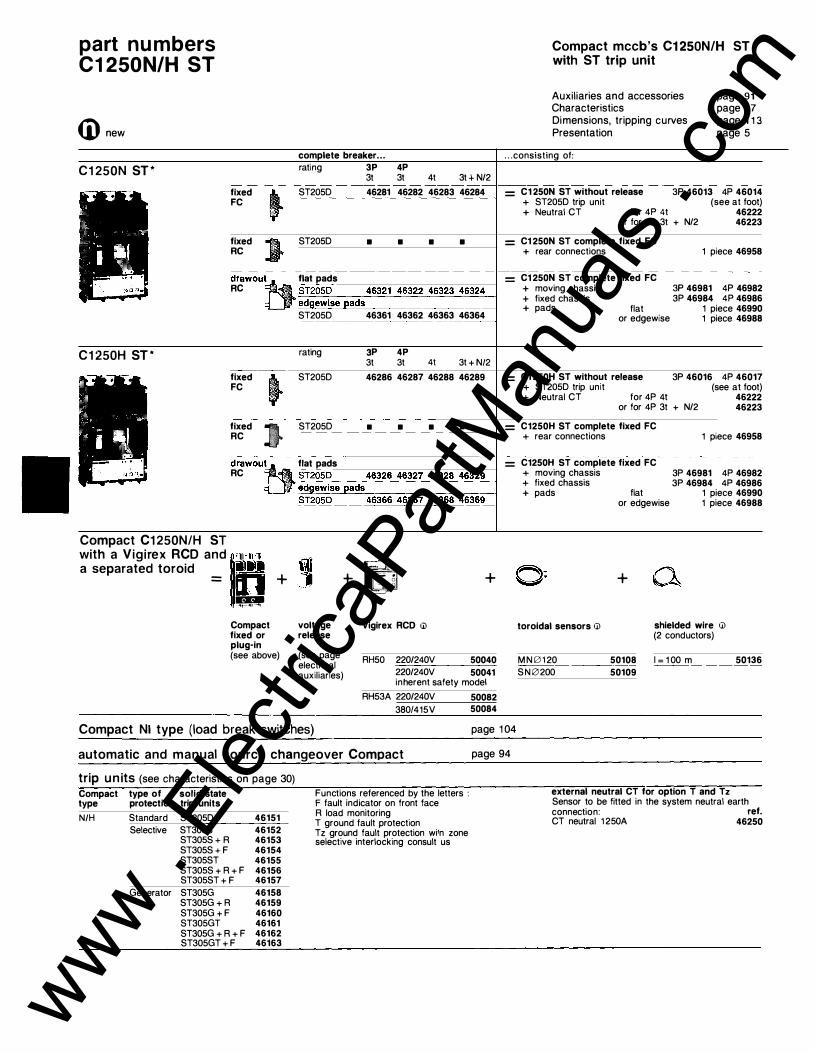
part numbers C1 250N/H ST
Ci) new
C1 250N ST*
fixed j FC
fixed ) RC
complete breaker .. . rating 3P 4P
3t 3t 4t 3t + N/2 ST205D 46281 46282 46283 46284
ST205D • • • •
drawou�-11 flat pads RC iJ ;;"';-c:-g"'2���!:�:=cs-e��_;a=d-,-s�4�6�3�2-1-'_-'4�6�3-2=2��4�6-3cc _2=3��4�6-3=2�4��
C1 250H ST*
fixed FC
fixed ). RC ,
ST205D 46361 46362 46363 46364
rating
ST205D
ST205D
3P 4P & & � & + N�
46286 46287 46288 46289
• • • •
drawoutti flat pads RC ; .:::.ST._,2::::0:.::5.:::.D __ __._46::::3:::-2:.::6_4'-"6:.::3=-27,_.4.=:63,..2-,8'-4_.,6-,3:--2.:::.9-l
' e�d�g�e�w�is=e�a=d=s�����-�---4
Compact C1 250N/H ST with a Vigirex RCD and ��1·.!1 .]. a separated toroid !llll•
= n + 1f!'!f!" Compact fixed or plug-in (see above)
ST205D 46366 46367 46368 46369
voltage release
(see page electrical auxiliaries)
+ �-;_� - 0 . - +
Vigirex RCD til
RH50 220/240V 50040 220/240V 50041 inherent safety model
RH53A 220/240V 50082 380/415V 50084
Compact mccb's C1 250N/H ST with ST trip unit
Auxiliaries and accessories Characteristics
page 91 page 1 7 page 1 1 3 page 5
Dimensions, tripping curves Presentation
. . . consisting of:
= C1250N ST without release + ST205D trip unit + Neutral CT for 4P 4t
3P 46013 4P 46014 (see at foot)
or for 4P 3t + N/2 46222 46223
= C1250N ST complete fixed FC + rear connections
= C1250N ST complete fixed FC + moving chassis + fixed chassis + pads flat or edgewise
= C1250H ST without release + ST205D trip unit + Neutral CT for 4P 4t
1 piece 46958
3P 46981 4P 46982 3P 46984 4P 46986
1 piece 46990 1 piece 46988
3P 46016 4P 46017 (see at foot)
or for 4P 3t + N/2 46222 46223
= C1250H ST complete fixed FC + rear connections
= C1250H ST complete fixed FC + moving chassis + fixed chassis + pads flat
or edgewise
+
1 piece 46958
3P 46981 4P 46982 3P 46984 4P 46986
1 piece 46990 1 piece 46988
toroidal sensors til shielded wire til (2 conductors)
MN0120 50108 1 = 1 00 m 50136 SN0200 50109
Compact Nl type (load break switches) page 1 04
automatic and manual source changeover Compact
trip un its (see characteristics on page 30) Compact type N/H
type of solid state protection trip units Standard ST205D Selective ST305S
ST305S + R ST305S + F ST305ST ST305S + R + F ST305ST + F
Generator ST305G ST305G + R ST305G + F ST305GT ST305G + R + F ST305GT + F
46151 46152 46153 46154 46155 46156 46157 46158 46159 46160 46161 46162 46163
Functions referenced by the letters : F fault indicator on front face R load monitoring T ground fault protection Tz ground fault protection wi1n zone selective interlocking consult us
page 94
external neutral CT for option T and Tz Sensor to be fitted in the system neutral earth connection: ref. CT neutral 1 250A 46250
www . El
ectric
alPar
tMan
uals
. com

� new
electrical auxi l iaries <IUxiUa_ry switches_ _ _ __ _
1 OF + 1 SO 3 OF + 1 SO
44900 44901
- -- - -- - - -1 CAM (for rotary handle or Visu module)
44627
double-throw micro-swi.cctccch�es'-------c--c "plugged-in" position '46963
"withdrawn" position 46964 vo_ltage release£1for remot� tri)J!ling)�=--=-� MX (shunt trip) AC 50/60 Hz or DC (V) 24 48/60 1 1 0/130 220/300 380/480 MN (undervoltage release) AC 50 Hz DC (V) (V) 48 44919 24
4491 0 4491 1 44912 44913 44914
44923 1 1 0/1 30 44920 48 44924
-- - --�---220/240 44921 1 1 0/ 130 44925 ------ -- -
-
---
380/41 5 44922 250 44926 --------- - -----AC 60 Hz (V) 1 1 0/1 27 44648 220/240 44928 ---
--- --
----
440 44649 --- --- -- - - - --MN (with time delay relay) 220 V AC 50/60 Hz = MN 1 1 0/130 V OC 44925 + time delay relay 250/700 ms 44930 - ---
- ---- -- - - -- - --
--- ----auxiUary wire block (see quantity� 44) __ _
�� moving part__ ___ _ _ __ _ ��· short wires 3 term. 42942 tor types NtH 6 term:- 42943 fixed pa_rt__ _ ___ _ _ __ _
tor all types 3 term. 42940 6 term. 42941
- - - - - - - ---pack of 24 female cliQs _ _ 429� connection set of auxiliaries (replace the standard auxiliary wire blocks)
connection set (6 wires) with extension cable additionnal connection set (6 wires)
adaptable motor mechanism
46989
41 928 (j)
type T (for remote control) --------Acso/60 Hz
_oc _ _ - -
M (VJ 1 1 0/1 27(1 ) 46928 24(1) 46917 220/24()(1) 46929 48/60(1) 46918 380/415(2)
-46930 1 1 0/1 25(1) 46919
440/48()(2) 46931 220/250(1) 46920 ---·-- ---- ----------
1 1 0/127(1) 46876 1 1 0/1 25(1) 46874
SOE alarm switch 46962 sealable cover (consult us) locking of the motor mech. 44876 by 1 key lock (not supplied) Ronis 1 351 .500 or Profalux KS5 824 04Z
(1) Direct supply motor mechanism (2) Motor mechanism supplied through an additional resistor
accessories direct rotary handle
with black toggl13_ _ _ �fi_�3
extended rotary handle with door locking _______ _
front door mounting short shaft 46935
( = 46933 + 42882)
long shaft 46937 ( = 46933 + 42884)
rear door mounting short shaft 46871 (J)
( = 46933 + 42889)
long shaft 46872 (J) ( = 46933 + 42897)
without door Joe�-------- _ _ _
ifiiffr, front door mounting
Ira a� short shaft 46938 �\. ( = 46933 + 45853)
accessories for converting direct rotary handle to extended handle
with door locking front door mounting
short shaft long shaft
rear door mounting short shaft long shaft
without door locking
42882 42884
42889 42897
short shaft 45853
shaft brack_-::e:.:.t __ _
for short shaft 42868 11r (always included on rotary � handles with long shaft)
--------------locking by padlocks or key lock
of the rotary handle (circuit-breaker in "OFF" position) by 3 padlocks (not supplied) built-in 1 Ronis key lock 1 351 .500 41 940 1 Profalux key lock 42888 KS5 824 04Z
for withdrawable circuit-breaker ------- - ---locking device for 1 or 2 46974 (j) keylocks (not supplied) keylocks for locking in draw-out position (free key) 1 keylock Ronis 13�()()�40 Ul
Profalux 42888 Ul KS5 824 04Z
1 set of 2 keylocks (1 key only) Ronis 1 351 .500 41 950 (J) ----- ---Profalux 42878 (J) KS 824 04Z
keylocks for locking in draw-in position (free key) 1 key Ronis 1 351 .500 41 945 Ul
Profalux 42900 (J) KS5 824 04Z ----- ----
of the toggle (in "OFF" position) � by 3 padloc
_ks_(_no_t_
s_uP_P_Iied_) 44936
-----mechanical interlocking (for fixed breakers with rotary handle) � mechanical device 46946
Compact mccb's C1 250N/H ST auxiliaries, accessories connection, spare parts
Characteristics page 1 7 page 1 1 3
page 5 Dimensions, tripping curves Presentation
key locks interlocking (for breakers with rotary handle and withdrawable breakers)
<eW- 1 set of 2 key locks 41950 q'G---"J� Ron is 1 35 �O<J_(
1_key _only) 1 set of 2 key locks 42878 Profalux KS5 824 04Z (1 key only)
sealing accesso_r� ________ ___ _ _
(\ for release, adjustment 46939 ItO � cover 44937
circuit label-holder - -- - --- -- -- - ---- --
--
---
set of 1 0 42976
(joor �t-out grommet Q for fixed breaker 44938 - ----
- --· ---
----
-
-
- -- - -- -- --
- -- --- ----Ill for withdrawable breaker 46977 lllio l:��:'"' /P<O) w/lh '"'"'"' 0
insulating shutters (for insulating the disconnecting contacts on fixed chassis)
! piec_e__ _ 46987 sealable terminal shields
• ....
short 3P (1 line side 4P or load side)
46993 46992
- - --------- -
----
- -long :3.f:_ _ _ _ _ 4699� (1 line side 4P 46995 or load side)
connection (see p. 55)
connectors for 4 Cu or AI cables 70 ( S ( 240
�� 1 set with 3P 46960 long terminal shield 4P 46994 (line side or load side)
---connection pads ___ _ __ _ __ ____ _ _ _ _
f_o_r fixed FC Compact !!fH/_1.. edgel'/i�e_pad�_1 _p_iece --�6988
for . fixecl_B�()m)Ja� f'.l/_li_ ��ew�s_e__pads_1_1)_iec�. _ �69_�
testing devices 54172
43362
3P/4P 44997
--
----- - - - - -- - -
- --
� toggle 46996
t& black toggle tor : rotary handle 45858 \ / ; ,.. , , ....... - ...J • . I -
www . El
ectric
alPar
tMan
uals
. com

part numbers CSOON/H/L ST to C1 250N/H ST
CD new
fixed Visucompact complete breaker . . .
Visucompact CSOON ST * rating 3P 4P 3t 3t
fixed FC � . .
ST205D •
Visucompact C1 000N ST * rating 3P 3t
fixed � ST205D • FC
Visucompact C1 250N ST* rating 3P 3t
fixed � ST205D • FC
drawout Visucompact
Visucompact CSOON ST * rating 3P 3t
RC ' ,1• ST205D • drawou� flat ads
1 edgewise pads ST205D
Visucompact C1 000N ST* rating
•
3P 3t
drawout:eJ..
flat ads RC . ST205D •
: edgewise pads
Visucompact C1250N ST*
ST205D •
rating 3P 3t
RC ST205D •
•
4P 3t
•
4P 3t
•
4P 3t
•
•
4P 3t
•
•
4P 3t
•
4t 3t + N/2
• •
4t 3t + N/2
• •
4t 3t + N/2
• •
4t 3t + N/2
• •
• •
4t 3t + N/2
• •
• •
4t 3t + N/2
• • drawouttt flat ads
�ed=g�
e�w�i�se�p�ad�s�------------------� ST205D •
Visucompact with a Vigirex �CD and 1.,1 . 11'1 separated tor01d iillllil
- o ----1t- '�r----'ll
Compact fixed or plug-in (see previous page)
voltage release
(see page electrical auxil iaries)
+
• • •
+
Vigirex RCD 11J
RH50 220/240V 50040 220/240V 50041 inherent safety model
RH53A 220/240V 50082 'lRn/.1.1 r:..v 50084
Visucompact mccb's CSOON ST to C1 250N ST
Auxiliaries and accessories Characteristics
page 93 page 1 7 page 1 1 3 page 5
Dimensions, tripping curves Presentation
. . .consisting of:
= C800N ST complete fixed FC + Visu module vaoo
with intermediate cover 3P 46907 4P 46908 without cover or accessories(1 ) 3P 46940 4P 46941
= C1 000N ST complete fixed FC + Visu module V1 250
with intermediate cover 3P 46909 4P 46910 without cover or accessories(1 ) 3P 46942 4P 46943
= C1 250N ST complete fixed FC + Visu module V1 250 3P 46909 4P 46910
with intermediate cover 3P 46909 4P 46910 without cover or accessories(1 ) 3P 46942 4P 46943
= C800N ST complete fixed FC + moving chassis 3P 46981 4P 46982 + fixed chassis 3P 46984 4P 46986 + pads flat 1 piece 46990
or edgewise 1 piece 46988 + safety shutters 46987 I1J + door cut-out grommet 46977 I1J
= C1000N ST complete fixed FC + moving chassis 3P 46981 4P 46982
3P 46984 4P 46986 + fixed chassis + pads flat
or edgewise + safety shutters + door cut-out grommet
1 piece 46990 1 piece 46988
46987 I1J 46977 Ul
= C1250N ST complete fixed FC + moving chassis 3P 46981 4P 46982
3P 46984 4P 46986 + fixed chassis + pads flat
or edgewise + safety shutters + door cut-out grommet
�= �- +
toroidal sensors I1J
M N 0 1 20 50108 SN0200 50109
a
1 piece 46990 1 piece 46988
46987 Ul 46977 I1J
shielded wire w (2 conductors)
1 = 1 00 m 50136 www . El
ectric
alPar
tMan
uals
. com

Visucompact mccb's CSOON ST to C1 250N ST : auxiliaries, accessories and connections
auxi l ia ries, accessories and connections specific to the fixed Visucompact auxiliary double-throw switch
locking of the Visu module in open position
terminal shields for Visucompact
OF standard or CAM early break depending on mounting 42906 2 OF 47757 by 3 padlocks (not supplied) by Ranis key lock 1 351 .500 (supplied)
built-in 41 940
by Profalux key lock KS5 824 D4Z (supplied) 42888 line side (phase separators) 3P/4P 47756 load side 3P 46999 4P 46995
connection for Visucompact CSOON ST line side, same as lnterpact IN 1000 see page 1 03 load side, same as Compact CSOON ST see page 87
connection for Visucompact C1000N ST line side, same as lnterpact IN1 000 see page 1 03 load side, same as Compact C1000N ST see page 89
connection for Visucompact C1 250N ST line side, same as lnterpact IN1 600 see page 1 03
____________________________ lo�a�d_s�id�e�·�s�a�m�e�a�s_C�o�m�p�a�c�t �C�1 2�5�0_N_S�T�----�s.ee page 91
auxi l iaries, accessories and connections specific to the drawout Visucompact same as drawout Compact of same rating '""fo"-r ....:V.:.:-is._..uc:::.co:::m.:.:p,...a:::c::.t _..c .... s.,_oo:::N_:__ ________________ _..s:::e.,_e _,p=a-"'ge=--:8'--7
for Visucompact C1 OOON see page 89 for Visucompact C1 250N see page 91
www . El
ectric
alPar
tMan
uals
. com

part numbers automatic and manual source changeover with TC1 60N/L, C1 01 to C1 250N/H/L
4D new
automatic source changeover
constitution
I C250N + C250N
TC1 60N/L *
I TC1 60 r·v 4 TC160 I
C250N/H/L *
� 'I-�
C401 /C400/C630N/H/L * C630N/H/L ST *
I g� �-v -1 c2so I
--
�v-� C63o
CSOON/H ST * C1 OOON/H ST *
C1 250N/H ST * �J - l caoo I -'V-- C1 000 C1 250
CSOOL ST * C1 000L ST *
� � -v C1000
3P fixed j • FC
3P fixed j • FC
fixed ) • RC
�gg-in lt• 3P
fixed j • FC
fixed ) • RC
��g-in lt• RC ..
3P fixed � • FC
fixed i • RC '
FC . ' plug-in �i •
RC ::
3P fixed � • FC .
-- -fixed ) • RC
3P fixed � • FC
fixed ) • RC .
l N normal l R replacement �y-------"\7---- - - -\-� automat1sm j
l load The automatic source changeover is equipped with : • different types of breakers N, H or L • different ratings (except TC1 60) • different trip unit (D, G, SA . . . )
4P Normal + replacement • TC1 60N TC1 60N w/o release and w/o release and MT module MT module
3P 42576 3P 42576 4P 42577 4P 42577
: or + or TC1 60L !11 TC160L!11 (see p. 68) (see p. 68)
4P Normal + replacement • : C250N/H/U41 + C250N/H/L (see p. 70) (see p. 70) •
• 4P Normal + replacement • C401 N/H/U41
(see p. 74) = to + C250N/H/L
C630N/H/L ST!41 (see p. 70) • (see p. 82)
• 4P Normal + replacement • C401 N/H/U41 + C401 N/H/L
(see p. 74) (see p. 74) = to + to
C630N/H/L ST!41 C630N/H/L ST • (see p. 82) (see p. 82)
• 4P Normal + replacement • C800N/H ST C800N/H ST
(see p. 86) (see p. 86) or or
= C1 000N/H ST + C1 000N/H ST • (see p. 88) (see p. 88) or or C1 250N/H ST C1 250N/H ST (see p. 90) (see p. 90)
4P Normal + replacement • C800L ST C800L ST (see p. 86) (see p. 86) or or
= C1 000L ST + C1000L ST • (see p. 88) (see p. 88)
Characteristics Dimensions, tripping curves Presentation
Note :
page 4 6 page 1 28 page 42
• the higher rating is always to the left, on normal incoming ; • for Compact C250 to C630 fixed FC, it is possible to associate a type L with a type N/H by using of spacing supports which balance the difference of depth (4).
-t- accessories + 1 plate with interlocking 42742 + 2 release units (see p. ) + 2 MT modules AC 50 Hz 220/240 V 2 X 42951
380/41 5 V 2 X 42952 + 1 automatism AC 50 Hz(21 220 V
380 v 41 5 v
+ accessories + 1 plate with interlocking + 2 motor mechanisms T250
220/240 V(31 AC 50 Hz + 1 automatism AC 50 Hz 220 v
240 v 380 v 415 v
+ accessories + 1 plate with interlocking + 1 motor mechanism T400/630
220/240 V!31 AC 50 Hz + 1 motor mechanism T250
220 V/240 V(31 AC 50 Hz + 1 automatism AC 50 Hz 220 v
240 v 380 v 41 5 v
42795 42796 42797
43743
2 x 43776 44888 44891 44889 44890
43744
44976
43776 44888 44891 44889 44890
---- -- ------
+ accessories + 1 plate with interlocking 44855 + 2 motor mechanisms T400/630
220/240 V(31 AC 50 Hz 2 x 44976 + 1 automatism AC 50 Hz 220 v 44888
240 v 44891 380 v 44889 415 v 44890
+ accessones ---+ 1 plate with interlocking 46947 + 2 motor mechanisms T800/1 000/1250
220/240 V!31 AC 50 Hz 2 X 46929 + 1 automatism AC 50 Hz 220 v 44888
240 v 44891 380 v 44889 415 v 44890
+ accessories - ··- ---
---+ 1 plate with interlocking 46947 + 2 motor mechanisms T800/1 000/1250
220/240 V!31 AC 50 Hz 2 X 46929 + 1 automatism AC 50 Hz 220 v 44888
240 v 44891 380 v 44889 415 v 44890 www .
Elec
tricalP
artM
anua
ls . c
om

4j) new
manual source changeover
with mechanical interlocking
C1 01 to 3P
C630N/H/L * fixed j • FC
fixed J • RC
��g-in ll •
C800 to C1 250N/H/L ST*
w1th key locks
:JHt� Jsl� :- >
C1 01 to C1250N/H/L
fixed j FC
fixed J RC
fixed .. FC If fixed J RC
(1) It is posible to associate a TC160N with a TC160L, or to compose a 3 TC1 60N/L changeover. Consult us. (2) A 220/240 V AC automatism is available with time delay "voltage failure on Normal supply" 0.1 to 30 s : 42899 (3) For 380 and 415 V, the adaptation resistor is included in the correspondent automatism. (4) To associate a Compact L type with a N or H type. (on fixed FC version only) . . . . . . on N or H type the part
3P •
•
3P •
•
The manual source changeover with mechanical interlocking is composed of : • 1 mechanical interlocking device • 2 Compact. The compact breakers are installed side by side, on panel or rails, without plate (for installation, see page 131) .
4P Normal + replacement • C101 to C101 to
= 630N/H/L + C630N/H/L (see p. 60 to 82) (see p. 60 to 82)
•
•
4P Normal + replacement • C8oo to C8oo to
- C1 250N/H/L ST + C1 250N/H/L ST -(see p. 86 to 91) (see p. 86 to 91 )
•
Th1s mterlockmg 1s easy set up by the addition, on each breaker, of the locking device, which can be equipped with 2 locks bearing the same key number. The one and only key will lock only one out of the breakers.
4P Normal + replacement • C101 to C101 to
C1 250N/H/L + C1 250N/H/L (see p. 60 to 82) (see p. 60 to 82)
•
• I
I
It is necessary to equip each breaker with a direct rotary handle, for mounting of the mechanism which interlocks the handles. The rating, the trip units and the number of poles of the breakers can be different. On the other hand, the versions �fixed, plug-in, front or rear connected) must be identical .
+ + +
+ + +
+ +
+
accessones 1 mechanical interlocking 44826 1 direct rotary handle per switch C1 01/C161 41310
C250 43820 C400/630 44820
accessories 1 mechanical interlocking 46946 1 direct rotary handle per switch
C800 to C1 250 46933
accessones 1 direct rotary handle per switch
C101/C161 C250 C400/630 C800 to C1250
1 set of 2 keys locks (1 single key) :
41310 43820 44820
46933
Ranis 1 351 .500 41 950 Profalux KS5 824 D4E 42878
www . El
ectric
alPar
tMan
uals
. com

switches 63 to 2500 A
for circuit control
coupling In the event of a normal supply failure, the switch enables the essential supply feeders, supplied via the standby source to be isolated from the non-essential side of the system .
distribution As a main incomer of the secondary switchboard, where protection is provided upstream, the switch enables the secondary switchboard to be isolated .
motor control When fitted to the line side of the motor, the switch provides either local or remote isolation of the motor from the system , for maintenance purposes etc.
which switch should you choose ?
lnterpact load break switches
Compact Nl load break switches
A simple high performance switch specifically designed for isolation and control, the range comes complete with a full range of accessories which include: • auxiliary contacts for on/off indication and control • auxiliary for early break • installation accessories • 3 and 4 pole versions • padlocking/changeover facility • compliance with B.S. etc AC22/23 rated
A high performance switch utilising the Moulded Case Circuit Breaker technology and hence offering the advantages of a MCCB, i .e. : • O.F. auxiliary contact for on/off indication • CAM switch for early break • MX shunt trip and MN undervoltage releases • Vigi module for earth fault protection, giving protection of the installation • adaptable remote control facility • available as source changeover system • full range of installation accessories • full range of connection accessories • padlocking/changeover- facility • compliance with B.S. etc AC22/23 rated
IN63T to IN2500
C1 01 Nl to C1 250NI
www . El
ectric
alPar
tMan
uals
. com

load break switches
4 switches, enclosures page
lnterpact load break switches 98 Compact load break switches 1 04 Fupact fuse-switches 106 individual enclosures 108 Panelpact enclosures 110
www . El
ectric
alPar
tMan
uals
. com

switches l nterpact load break switches IN63T to IN2500
. ' .
-
l I . ·\ .
presentation lnterpact is a range of 63 to 2500 A, 3 or 4-pole switches, of moulded case construction with double break contact configuration. They are used for control and isolation of distribution circuits: • main switch, • coupling, • head of divisional switchboard, • " motor" circuit control, • local isolating device, • etc.
The lnterpact range can be fitted with auxiliaries such as: • auxiliary contacts, • installation accessories, • connection accessories, • etc. (for further details refer to following pages)
positive break indication All lnterpact devices provide isolation with positive break indication. Their control handle can only indicate the "off" position if all the contacts are indeed open and a proper distance apart.
installation lnterpact switches are installed on a panel or on metal supports, and can operate in all positions.
Degree of protection bare unit with terminal shields unit in enclosure or cubicle with
tropicalization
direct ctrl extended ctrl
IP405 IP405 IP557
lnterpact switches and their auxiliaries are tropicalized . They comply with treatment 2 of the NF C63-100 standard; relative humidity of 95 % at 45 °C, or 80 % at 55 °C (hot and wet climate).
standards lnterpact switches comply with: • IEC 408 recommendations, • French Standard NF C63-130,
description characteristics
Characteristics Dimensions Part numbers
page 5 page 1 1 3 page 57
www . El
ectric
alPar
tMan
uals
. com

ID new
auxi l iaries and accessories
CAM switch
Extended and lateral rotary handle
shaft bracket
Locking by padlocks or. key lock
for IN63T to IN160T
Interlocking
mechanical interlocking
connection
Direct connection IN63T bare cables
for IN250 to IN2500
key locks interlocking
~ Connection with accessories Polybloc connectors for IN 125T for IN 125T and I N 1 60T to IN630
The CAM switch is a common point auxiliary changeover contact which, depending on how it is fitted, can provide : • either the OF function, connected with the lnterpact "on" or "off" position, • or the CAM function, for early break or early make (break only on IN63T). Note : a block with 2 changeover contacts is also available for the IN400 to IN2500 (OF function only).
Lateral rotary handle The standard di rect rotary handle on lnterpact IN63T to IN 160T switches may be converted into a lateral direct rotary handle by an optional accessory kit. Extended rotary handle (IP557) is obtained by adding to the standard rotary handle an accessory kit comprising : • an escutcheon to be fitted in front of the door to accomodate the handle,
To lock the lnterpact in the "open" position, the handle includes : • a padlock fitting for 3 padlocks (not supplied) built into the toggle of all the lnterpact devices (1 padlock only for IN63T); • a pre-drilled location on the IN250 to IN2500 to fit 1 key lock (supplied on option), with a key held captive when the lnterpact is in the "closed" position.
Mechanical interlocking This interlocking equips the lnterpact IN63T to IN630. It is achieved by a mechanism which connects the handles of 2 direct control lnterpacts to constitute a manual source changeover. This device prevents both switches from being closed at the same time, but enables them to be opened.
The terminal shields are sealable insulating accessories used to avoid direct contacts with live parts. Depending on the switch type, the lnterpact can be fitted : • either with short or long terminal shields, • or with phase separators.
IN1 000 and IN1600
angle terminals for IN 125T
spreader for iN400 and IN630
for IN1000 and I N 1 600 to IN630 � � �
auxiliaries, accessories
Possible combinations lnterpact block block block
1 OF 2 OF . CAM IN63T IN125T,IN1 60T,IN250 IN400,1N630, IN1 000, IN 1600, IN2500
• an extension shaft.
+ 1 i + 1
+ 1
The extended rotary handle does not alter the visible break indication function, and can be optionally fitted with : • a shaft bracket to eliminate vertical play at the end of the shaft. • a door latch which only allows the door to be opened when the handle is in the "open" position.
Locking possibilities lnterpact 1 padlock key lock
0 hasp type (mm)
IN63T to IN160T , 5 to 8 · without IN250 5 to 8 ' Ronis 1 351 .500 IN400 to IN630 · 6 to 8 · or Profalux IN1 000 to IN2500 i 5 to 8 KS5 824 D4Z
Interlocking by key locks This interlocking equips the lnterpact IN250 to IN2500. It consists of equipping both the lpterpacts with a standard interlock associating 2 key locks and a single key. This solution enables 2 geographically distant switches to be interlocked.
The terminal shields are always supplied with their sealing accessories.
Fitting possibilities lnterpact : term. shields phase
short · long separators IN63T to IN1 60T IN250 to IN630 • IN1000 to IN2500
edgewise pads for IN1000 and IN 1600
• •
•
connectors for IN2500 www .
Elec
tricalP
artM
anua
ls . c
om

switches lnterpact load break switches IN63T to IN2500
4j) new
lnterpact
characteristics rated current (A) at so•c rated service current {A) AC 50/60 Hz cl. AC 22 (U � 400 V)
cl. AC 23 (U � 400) DC cl. DC 23 (U � 250) (11
rated voltage (V) AC 50/60 Hz DC
number of poles short circuit making current (kA peak) withstand current (kA rms for 1 s.) endurance (CO)
protection upstream protection
auxiliaries and accessories adaptable auxiliaries
adaptable auxiliaries
installation version
overall dimensions (mm)
- - -----�-�--weight (kg)
mechanical electrical at 4 15 V
Compact circuit breaker (61 (lsc max. = breaking capacity of the CB)
aM type fuse (21 max. (A) lsc max. (kA rms)
g 1 type fuses max. (A) lsc max. (kA rms)
OF switches CAM switch terminal shields connection accessories padlocking device locking device extended rotary handle mechanical interlocking key lock interlocking
connection fixed
3P 4P 3P 4P
(1) Number of poles having to peform the break : 1 at 48 V, 2 at 1 25 V. 4 at 250 V. (2) aM fuses must be systematically associated by a thermal release. (3) Phase separators. 14\ With no time delaved trio unit.
IN63T
63 63 63 63 660 500 3, 4 1 5 2.5 1 5000 1 000
NC100 C10 1N C161 N
63 50 80 50
• • • • •
• •
FC • H w 85 1 20 85 1 20 0.75 0.80
D 1 05 1 05
characteristics
Description Dimensions Part numbers
• IN1 25T
1 25 1 25 1 25 1 25 660 500 3, 4 20 5.5 15000 1 000
C161 N/L
1 25 50 1 60 50
• • • • •
• • ·- .
FC RC • • H w D 1 28 1 70 1 05 1 28 1 70 1 05 1 .4 1 .5
page 5
page 1 1 3 page 57
• I N 1 60T
1 60 1 60 1 60 1 60 660 500 3, 4 20 5.5 1 5000 1 000
C161 N/H/L
1 25 50 1 60 50
• • • • •
• •
FC RC • • H w D 1 28 1 70 1 05 1 28 1 70 1 05 1 .4 1 .5
www . El
ectric
alPar
tMan
uals
. com

- ¥7-
I •
IN250 IN400 IN630 IN1 000 U) IN1600 U)
250 400 630 1 000 1 600 2500 250 400 630 1 000 1 600 250 400 500 630 250 400 630 1 000 1 600 660 660 660 660 660 500 500 500 500 500 3, 4 3, 4 3, 4 3, 4 3, 4 3, 4 30 40 50 75 75 1 05 8.5 1 2 25 35 35 50 1 0000 1 0000 1 0000 1 500 1 500 1 500 1 000 1 000 1 000 500 250 250
C250N/H/L C40 1 N C630N/H C800N/H ST (5) C1 000N/H ST (5) Compact CM (4) (5) C400N ST C630N/H ST C1 000N/H ST (5) C1 250N/H ST (5)
C1 250N/H ST (5) C1 000L ST (7) C800/C1 OOOL ST(7) Compact CM (4) (5)
250 400 500 1 00 1 00 1 00 315 500 630 1 00 1 00 1 00
• • • • • -· -----· -------• • • • • • • • • • (3) . (3) • (3� • • • • • • • • • • • • • • • • • • • • • • • • • • • ---·----• • • • • •
FC RC FC RC FC RC FC FC FC • • • • • • • • • H w D H w D H w D H w D H w D H w D 1 70 230 1 51 230 280 1 70 230 280 1 70 300 340 200 Ill 300 340 200 Ill 440 340 31 1 .5 11l 1 70 230 1 5 1 230 280 1 70 230 280 1 70 300 410 200 300 410 200 440 410 31 1 .5 2.7 4.3 4.8 1 2 11l 1 5 11l 35 11l 2.8 4.7 5.3 1 5 1 8 45
www . El
ectric
alPar
tMan
uals
. com
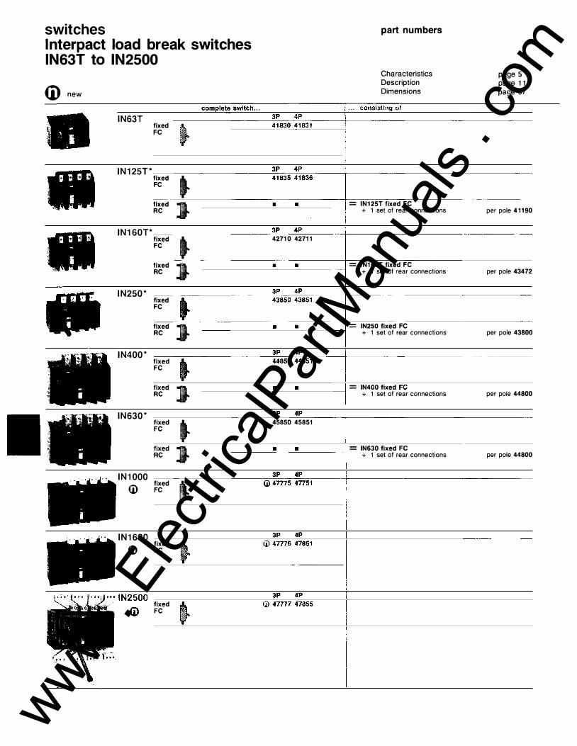
switches lnterpact load break switches IN63T to IN2500
4D new
' '
.. I
' '
I
IN63T
IN 1 25T*
IN1 60T*
IN250*
IN400*
IN630*
IN1 000
U>
IN1 600
U>
fixed FC
fixed FC
fixed RC
fixed FC
fixed RC
fixed FC
fixed RC
fixed FC
fixed RC
fixed FC
fixed RC
fixed FC
fixed FC
fixed FC
� J � J � J
J � J j
4271 0 4271 1
45850 45851
part numbers
Characteristics Description Dimensions
= IN1 25T fixed FC + 1 set of rear connections
= IN1 60T fixed FC + 1 set of rear connections
= IN250 fixed FC + 1 set of rear connections
= IN400 fixed + 1 set of rear connections
= IN630 fixed FC + 1 set of rear connections
page 5 page 1 1 3
page 57
per pole 41190
per pole 43472
per pole 43800
per pole 44800
per pole 44800
www . El
ectric
alPar
tMan
uals
. com

electrical auxi l iaries auxiliary contacts
1 OF or CAM IN63T to IN1 60T IN250 to IN2500 2 OF IN400 to IN2500
accessories
with black toggle red toggle IN63T IN1 25T/IN1 60T IN250 IN400/IN630
lateral rotary handle with black toogle IN63T IN1 25T/1 60T
red toogle only IN63T IN1 25T/1 60T
41843 42906
47757
built-in
41 847 41 848 44847 45859
41826 41827
41 822 41 824
accessories for converting direct handle to extended handle
-- IN1000 to IN1600 �'\\ IN2500
lfl.. IN63T to IN1 60T -........... IN250 to IN630 41839 45853 47753 47763
for lateral rotary handle IN1 25T/IN1 60T 41825
locking of the toggle by 3 padlocks built-in (1 padlock on IN63T)
by key lock (in open and closed position) for IN250 to IN2500 1 Ronis key lock 1 351 .500 41940 1 Profalux key lock 42888 1<25 B24 D4Z
door locking for switch in closed position (only for extended rotary handle)
IN63T to IN160T 41840 IN250 to IN2500
mechanical interlocking (only for direct rotary handle)
47754
IN63T to IN160T 41 846 IN250 to IN630 45856
key lock interlocking for IN250 to IN2500
q 1 set of 2 Ronis 1 351 .500 41 950 ��,;r.,.. key locks (1 single key)
1 set of 2 Profalux 42878 KS5 B24 D4Z key locks (1 single key)
sealable terminal shields short term. shields (1 set) IN250 3P/4P 43830 IN400/IN630 3P/4P 44830 long term. shields (1 set) IN63T 3P/4P 41841 IN1 25T/IN1 60T IN250 IN400/IN630
phase separators (1 set) •"lliiiiiii IN 1 000/1 N 1 600
_..-- IN2500
3P/4P 41842 3P/4P 43832 3P/4P 44832
3P/4P 47756 3P/4P 47860
connection Polybloc terminal (for bare cables)
I J IN1 25T/IN1 60T � 6 cables S ..; 1 0°
connectors for bare cables
IN160T 1 6° ..;s ..;95°
IN250T
07100
per pole 42715
1 6° ..;s .;;;; 1 85° per pole 43813 extension of rear connections (compulsory when per pole 43848 spacing supports)
IN400/IN630 single connector per pole 44813 ( 1 cable S ..; 300° ) double connector per pole 44814 (2 cables S ..;2400 )
spreader IN400/IN630
� IN1000 (1 set)
� IN1600 (1 set)
connectors IN2500
spare parts
per pole 47758 per pole 47858
3P 44841 4P 44842
3P 47760 4P 47761
3P 2 X 47760 4P 2 x 47761
1 piece 55675
black toggle (for direct rotary handle) A IN63T 41 844 'li' �IN71�2�5�T/�IN�1�6�0�T�--------4�1�8�4=5
'\\ IN250 44846 IN400/IN630 45858 IN1000/IN1600 47759 IN2500 47862
auxiliaries, accessories connection, spare parts
www . El
ectric
alPar
tMan
uals
. com

switches Compact load break switches C1 01 Nl to C1 250NI
Cj) new
Compact
by fuses (lsc max.
models with adaptable elements
adaptable auxiliaries
adaptable accessories
i nstallation
(1) According to IEC standards, AC 21, AC 22 and AC 23 classes are corresponding to a normal operating in alternative current, and DC 21 , DC 22 and DC 23 to a normal operating in direct current.
(2) Number of pole having to perform the break: ?P ::�t ?r:;.n \1 AD ""t &;;.tV'\\1·
characteristics
description dimensions
page 1 0 page 1 1 3
www . El
ectric
alPar
tMan
uals
. com

Cj) new
C101 N I * ti)
C161 N I *
TC1 60NI *
C250NI*
C401 N I * ti)
C630NI *
fixed FC
fixed RC
complete switch .. . 2P 3P 4P 39702 39703 39704
part numbers
Description Dimensions
. . . consisting of:
page 1 o page 1 1 3
• --.--.-��--- ----+--�C�1�0�1 �N"'"'I�f�ix_e__,d,..'F=-c�------------ �---
------- --�------��--- + 1 set of rear connections(1 ) per pole 39998
40902 40903 40904
• • •
C101 Nl fixed FC + 1 set of plugs per pole 39985 + 1 plug-in base FC/RC 2P 39972 3P 39973 4P 39974 + 1 set of short term. shields 2P/3P 39983 4P 39984
per pole 41 190
C161 Nl fixed FC + 1 set of plugs per pole 41 194 + 1 plug-in base FC/RC 2P 41 195 3P 41 1 96 4P 41 197 + 1 set of short term. shields 2P/3P 42960 4P 42961
TC160NI without MT module and release, fixed FC
+ 1 switch module 2P 42570 3P 42571 4P 42572
2P/3P 42405 4P 42406 + 1 MT module 220/240V AC
(other voltages, see page 69) 42951
ccfi-xe-d-:---�=------. ---. �--.� --- ---- --l--=-r=c�16=-0c-:N-:-clccfc-ix-e-d:-cF=c�----RC
____ _cc_ ___ �------�� + 1 set of rear connections per pole 42450
I ·nl +--�T�C�1�6�0�N�I �fi-x-ed�F=c _ ______________ �--�RCC
ug-t 11 ---•--�--•-- - -•-- -------+ 1 set of plugs per pole 42452 .. + 1 plug-in base FC/RC 2P 42457 3P 42458 4P 42459 + 1 set of short term. shields 2P/3P 42960 4P 42961 + 1 3-terminal block
fixed j FC
fixed i RC
43325 43326 43327 moving part 42944 fixed part 42940
C250NI without release, fixed FC 2P 43001 3P 43002 4P 43003
+ 1 switch module 2P/3P 43323 4P 43324
----'•=--- • --•--� -------+ = C250NI fixed FC + 1 set of rear connections per pole 43800
------�--------- --------+-=--:Cc-:2c=5c:-O:-:N""I cofix-e-d""F=c=---�·--�----- ----plug-ini , �g 41 --fixed FC
fixed RC � ..
• • • -----
44792 44793
+ 1 set of plugs per pole 43802 + 1 plug-in base FC/RC 2P 43809 3P 43810 4P 4381 1 + 1 set of short term. shields 2P/3P 43829 4P 43830
= C401 Nl without release, fixed FC 3P 44661 4P 44662
+ 1 switch module 3P 45375 4P 45376 • --.--��
-----+---:C'"4�01NI fixed FC
+ 1 set of rear connections per pole 44800
FC -fl. + 1 set of plugs(t ) plug-inl _____ __-,•'----""'•'-----------1 = C401NI fixed FC
RC -{1" + 1 plug-in base FC/RC + 1 set of short term. shields
per pole 44802 3P 44810 4P 4481 1 3P 44829 4P 44830
��ed � fixed ) . . RC j plug-incj·
.. ·· �.·· ..
�g �·
45379 45380 C630WI without release, fixed FC 3P 45002 4P 45003
+ 1 switch module 3P 45375 4P 45376 -�----------·�--- ----+---ccc-:-:-:�c---c-=c=cc-- ---� �--------C630NI fixed FC • •
• •
+ 1 set of rear connections
C630NI fixed FC + 1 set of plugs + 1 plug-in base FC/RC + 1 set of short term. shields
per pole 44800
per pole 44802 3P 44810 4P 4481 1 3P 44829 4P 44830
CBOONI *ST fixed C1 250NI *ST
FC C800NI C1250NI
46025 46026 46028 46029
fixed RC ) • •
• •
C800 Nl or G1250 Nl fixed FC + 1 rear connections 1 piece 46958
--- -+---:C�8�0�0:-:N=-I o-r-C�12�5=-0�N�I �fi-xe-d�F�C-------- . + 1 moving chassis + 1 fixed chassis FC/RC + pads flat
3P 46981 4P 46982 3P 46984 4P 46986
1 piece �����
www . El
ectric
alPar
tMan
uals
. com

switches Fupact fuse-switches UC50 to UD630T
description, characteristics
characteristics (IEC 408)
Fupact fuse-switch fuse size rated current AC 22 (A) without stricker vertical installation
with stricker
horizontal installation without stricker
with stricker
rated current AC 23 380-41 5-440-500 v (A) 660 V rated voltage (V) AC 50/60 Hz(4)
rated isolation voltage (V)
application The Fupact fuse-switches are designed for: • the control, protection and isolation of switching of highly inductive loads (transformers, capacitors . . . ) ; • the protection and isolation of motor control circuits. They are used in all AC and DC circuits at voltages up to 660 V. Operation The Fupact switching technology offers optimum safety: • Fupact fuse switches, unlike fusedisconnectors, are suitable for ON-LOAD operation. • the Fupact's are fixed-mounted and isolation is provided on both the line and the load sides of the fuses. The fuses are therefore isolated when the switch is open .
Positive contact indication The handle can only indicate the OFF position if all the contacts are actually open. With its guaranteed contact seperation, the Fupact affords maximum safety.
ucso UD63 UC125 UC125 1 4 x 51 DIN 00 22 x 58 DIN 00
40°C 50 63 1 26- 1 25 60°C 40 50 !QQ. __ c.!Q_� 40°C 37 47 94 94 --�- ··- rc---
- ·-- C=----60°C 28 75 75
Dimensions page 1 1 3
models The Fupact range includes: • 2 items for cylindrical fuses (UC50 and UC125), • 6 items from 63 to 630 A for fuses of D IN type (UD63-UD125-UD160-UD250TUD400T-UD630T) . Number of poles: • 3 poles with 3 fuses; • 4 poles with 3 fuses, neutral broken and unprotected (provided l ink) ; • 4 poles with 4 fuses (except UD63).
standards Fupact fuse-switches comply with international IEC standard 408, with British Standard BS 5419 , German standard VDE 0660, VDE 01 13 , Det Norske Veritas, AS 1 775-1 975, UL 512 .
approvals UL and ASTA certified (UD 160 to 400 pending) Lloyd's Register of Shipping, Germanische Lloyd's, Register of Shipping of the USSR.
tropicalization All climates (treatment 2) .
UD160 UD250T UD400T UD630T DIN 00(1) DIN 1 DIN 2 DIN 3 -·---
---::-::-�----- �- 250 400 630
1 28 200 320 504 -· 1 20 1 88 296 472 ---- �--�-- ---�-96 1 50 224 378 m· �-- 1�-'144 ..
40°C 45 57 224 360 567 --f---�
- -
-
-- "Tis. ·-f-C-------60°C 36 45 90 90 1 80 288 454 40°C r=� -
- - - -1-=::-----108- ---
--:-::------··
1--·--
--
-
34 42 �- 78 1 56 272 425 60°C 27 34 67 67 86 1 34 216 340
--f-C--------50 63 1 1 5 1 1 5 1 25 250 400 630
-
--
--45 40 63 �-�-- 63 250 �- 630
--
---rsso-- --660 660 660 660 660 660 660
··-1--------1-----·-· -- f------750 750 750 750 750 750 750 750
--
-
--
rated fuses short-circuit capacity at 500 V (kA) 50 50 �� 1 00 1 00(2) 1 00 1 00 f-=-::-·-· 80 breaking capacity AC 23 380-41 5-440-500 v (A) 660 V breaking capacity DC 1 1 0 V (2 poles in series) (A) UR :;:; 1 5 ms 200 V (2 poles in series) operational power AC 23 380 V (kW) 4 15 v
500 V 660 V
mechanical endurance (CO) weight without fuse 3P 3 fuses (kg) 4P 4 fuses auxiliary switches breaking capacity
thermal rating
--500 - --
350 300 - -250 22 30 30 30 1 0000 1 .6 1 .9
� 500 __
350 300
--
250 30 30 30 30 1 0000 1 .6 1 .9
800 ___ 800 ---500 500 'sao 500
. ----
--- �--�-55 55 ---· 60 60 75 75 55
-� rss---7500 7500 1 .8 1 .8 2.3 2.3
4 A at 415 V AC1 1 ; 1 A at 1 1 5 V DC1 1 1 0 A
�0 3200 3200 4500 500 3200 3200 4500 �----
1 600 �-- - 1 600 3200 400 1 200 1 600 2000 �----
1 30 21 0 3 15 '65- ----1 40
· ·--r:-:-::----- r-::-:-::--·---230 340 80
f-:-::c'-· 280 400 1 70
55 230 330 -- �
�---
--
· · · - 540 --7500 5000 5000 3000 1 .8 6.9 7.8 1 5.5 -2.3 c.I-9 8.8 1 9
www . El
ectric
alPar
tMan
uals
. com

ID new
part numbers Fupact with standard handle and short shaft (without fuses)
accessories et auxiliaries
Fupact 3P 4P 4P type 3 fuses 3 fuses(t ) 4 fuses
UC50 49001 49002 49003 UD63 49004 49005 UC1 25 49006 49007 49008 UD125 49009 49010 49011 UD1 60 49012 49013 49014 UD250T 49210 49211 49212 UD400T 49216 49217 49218 UD630T 49219 49220 49221
fuse cover (compulsory when the fuse-switch is mounted without door or escutcheon)
blown fuses indicating device for fuse with striker
terminal shields (for one side)
auxiliary switches
auxiliary switch cover
long shaft fort extended rotary handle
neutral link and its support
locking device (key lock not supplied) black toggle
part numbers accessories, auxiliaries
3P 4P 3 fuses 3 fuses(1)
UC50 49024 49025 UD63 49026 49027 UC1 25-UD1 25-UD160 49028 49029 UD250T 49237 49237 UD400T 40238 49238 UD630T 49250 49251 UD50 49057 49058 UC125 49059 49060 UD250T 49080 49081 UD400T 49083 49084 UD630T 49086 49087 UC125-UD1 25-UD160 49034 49035 UD250T (per pole. 49257) 3x 49250 4 X 49255 UD400T (per pole. 49257) 3 x 49257 4 X 49257 UD630T (per pole. 49257) 3 x 49257 4 X 49257 UC50-UD63 1 OF 49056 UC1 25-UD1 25-UD1 60 1 OF 49041 UD250T-UD400T-UD630T 1 OF 49089 UC50-UD63 UC125-UD125-UD160
4P 4 fuses
49025
49029 49247 49248 49251 49058 49060 49082 49085 49088 49035 4 X 49255 4 X 49257 4 X 49257
2 OF 49040 2 OF 49042 2 OF 49090
49045 49046
UD250T-UD400T-UD630T included with OF contacts UC50-UD63-UC1 25 49048 UD1 25-UD 1 60
UD250T-UD400T-U D630T 49245 UD50-UD63 49273 UC125-UD125-UD160 49274 UD250T-UD400T 49275 UD630T 49276 UD250T-UD400T-UD630T 49053 UC50-UD63-UC1 25 49054 UD125-UD160
UD250T-UD400T-UD630T 49055
www . El
ectric
alPar
tMan
uals
. com

individual enclosures weatherproof metal enclosures
CD new
part numbers metal enclosures
accessories locks for rotary handle, switch in • OFF • position
dimensions (mm)
direct rotary handle
for Compact C1 01 N to C630N
for Vigicompact C101N to C630N
for Compact C8oo to C1 250N ST
for lnterpact IN63T to IN630
for Fupact
description Weatherproof metal enclosures are available for the following circuits breakers: • Compact and Vigicompact C1 01 N to C1 250N as well as their variations, all types of trip unit, in fixed front connected version; • lnterpact I N63T to IN630. The weatherproof metal enclosures include: • a plate equipped for the mounting of fixed front connected, two, three or four pole circuit-breakers; • a door cutout for the fixing of the rotary handle.
characteristics Degree of protection: IP 55. 1 .5 mm thick electro-zinc coated steel sheet. Beige epoxy powder painting. Cable entry through removable bottom plate. Secured by 4 holes on the back or by external fixing lugs (supplied).
C101N C161 N C250N C400N C630N 39960 li) 41932 43990 44990 45990
C101 N C161 N C250N C400N C630N 39959$ 41933 43991 44991 44991
C800N C1 000N C1 250N 46888 46888 46888
IN63T IN125T IN250 IN630 IN160T IN400
41853 41856 43843 44941
consult us
description, characteristics part numbers dimensions
control and locking Compact C1 01 N to C630N ST Vigicompact C1 01 N to C630N ST • direct rotary handle actuated through the door, with watertight escutcheon; • locking of the breaker in • OFF •
position by 3 padlocks (not supplied). Available on request: o locking of the breaker in • OFF •
position with a Ranis lock 1 351 .500 or " Profalux lock KS5 824 D4Z.
Compact C800 to C1 25.0N ST • waterproof extended rotary handle; • locking of the breaker in • OFF •
position by 3 padlocks (not supplied). • locking of the door when the breaker is in • ON • position .
lnterpact IN63T t o IN630 • extended rotary handle; • locking of the switch in • OFF • position by 3 padlocks, not supplied (only one padlock for IN63T). Available on request: o locking of the switch in • OFF • position with a Ranis lock 1 351 .500 or a Profalux lock KS5 824 D4Z (except IN63T, I N 1 25T, IN 1 60T). o locking of the door when the switch is in • ON • position.
including: • empty enclosure with plate and drilled door, • 1 direct rotary handle, • 1 watertight escutcheon for rotary handle, (to complete with Compact 2P, 3P, 4P, fixed FC)
• empty enclosure with plate and drilled door, • 1 direct rotary handle, • 1 watertight escutcheon for rotary handle, (to complete with Vigicompact 3�, 4P, fixed FC)
• empty enclosure with plate and drilled door, • 1 extended rotary handle (front door
mounted), • accessories for watertight rotary handle, (to complete with Compact 3P, 4P, fixed FC)
• empty enclosure with plate and drilled door, • accessories for converting direct to eJCtended
rotary handle (to complete with lnterpact 3P, 4P, fixed FC)
by 3 padlocks (1 padlock for IN63T), padlock not included built-in by keylocks for C101 N to C1250 1 Ron is key lock 1 351 .500 and lnterpact IN250 to IN400 1 Profalux key lock KS5 824 D4Z
lnterpact IN63T to IN1 60T lnterpact IN250 to IN630
extended rotary handle
41940 42888 41840 45854
Compact Vigicompact Compact lnterpact C101 N C250N C630N C 1 0 1 N C250N C800N ST C1 000N ST IN63T IN125T IN250 C161 N C400N C 1 61 N to C630N C1 250N ST IN 160T to IN630
H 400 600 800 500 800 825 800 400 400 600 w 300 400 600 400 600 550 600 300 300 400 D 200 200 275 200 275 275 275 1 50 1 50 200
www . El
ectric
alPar
tMan
uals
. com

individual enclosures weatherproof polyester enclosures
4D new
part numbers polyester enclosures for Compact
C1 01 N to C630N
for Vigicompact C101 N to C630N
description Weatherproof polyester enclosures are avai lable for the following circuits breakers: • Compact and Vigicompact C 1 0 1 N to C1 250N as well as their variations, all types of trip unit, in fixed front connected version; • lnterpact IN63T to IN630. The weatherproof polyester enclosures include: • a plate equipped for the mounting of fixed front connected, two, three or four pole circu it-breaker; • a door cutout for the fixing of the rotary handle.
characteristics Degree of protection: IP 55. Beige polyester. Shockproof and corrosionproof. The screwed transparent cover can be fitted with lead seals. Cable entry through removable bottom and top plates. Secured by 4 holes on the back.
C 1 01 N C161 N C250N C400N C630N 39958 Ul 42987 43995 44995 44995
C101N C161 N C250N C400N C630N 39957 ill 41937 43996 44996 44996
description, characteristics part numbers dimensions
control and locking Compact C 1 0 1 N to C630N Vigicompact C1 01 N to C630N ST • extended rotary handle; • locking of the breaker in " OFF .. position by 3 padlocks (not supplied). • locking of the cover when the breaker is in " ON .. position . Available on request: o locking of the breaker in " OFF .. position with a Ranis lock 1 351 .500 or a Profalux lock KS5 B24 D4Z.
lnterpact IN63T to IN630 • extended rotary handle; • locking of the switch in " OFF . . position by 3 padlocks not supplied (only one padlock for IN63T). Available on request: • locking of the switch in " OFF • position with a Ranis lock 1 351 .500, or a Profalux lock KS5 B24 D4Z (except IN63T, I N 1 25T, IN1 60T). • locking of the cover when the switch is in " ON .. position.
i ncluding: • empty enclosure with plate and drilled door, • 1 direct rotary handle, • 1 watertight escutcheon for rotary handle, (to complete with Compact 2P, 3P, 4P, fixed FC)
• empty enclosure with plate and drilled door, • 1 direct rotary handle, • 1 watertight escutcheon for rotary handle . (to complete with Vigicompact 3P, 4P , fixed FC)
--------- - -------- - - -
accessories locks for rotary handle, switch in " OFF . . position
for lnterpact IN63T to IN400
tioor locking, switch in closed position
dimensions (mm) extended rotary handle
-- ---Compact C101N C250N C400N C161 N C630N
H -�-"
540 720
IN63T IN1 25T IN250 IN400 • empty enclosure with plate and drilled door, IN 16 1T IN630 • accessories for converting direct to extended 41858 41 859 43844 44942 --
rotary handle, (to complete with lnterpact 3P, 4P, fixed FC)
built-in by 3 padlocks (1 padlock for IN63T), padlocks not included ------------
by keylocks for C1 01 N to C630N , 1 Ron is key lock 1 351 .500 and lnterpact IN250 to IN400 1 Profalux key lock KS5 924 D4Z
lnterpact IN63T to IN1 60T lnterpact IN250 to IN630
---.--- - · ----- �-Vigicompact lnterpact C 1 01 N C250N IN63T IN125T IN250 IN400 C161 N to C630N IN 160T IN630
540 720 270 360 540 720
41940 42888 41840 45854
· · - ----
------ ·
-· --- - ---------· ----- - -----w 270 270 360 270 360 270 270 360 360 0 -- --- --- - ---------·-
235 235 235 235 235 1 85 185 1 85 1 85
www . El
ectric
alPar
tMan
uals
. com

panel boards Panel pact
(i) new
H
Wd
presentation Panelpact mccb's distribution boards are enclosures designed for the installation of several Compact circuit-breakers. They are available in five sizes with 6 to 22 ways and in two types : • C1 for incoming breaker up to 800A, • C2 for incoming breakers up to 1 OOOA. Standards : Pnalepact complies wit IEC 439-1 . 1 985 and BS 5486. part 1 . 1 977.
characteristics
Electrical characteristics : • rated insulation voltage : 660 V AC - 500 V DC. • rated frequency : 50/60 Hz. �� C1 � current of busbars 800 1 000 maximum rated (A)
rated short-time withstand (kA rms/1s)
rated peak withstand (kA) rated conditional short-circuit (kA rms)
Enclosure
35 50
75 1 05 50 70
• Panelpact mccb distribution boards are totally enclosed, dust protected and vermin proof. The degree of protection of the standard enclosure is IP 31 for indoor installation. The pan assembly can be fitted in an IP 55 enclosure for outdoor installation. • the enclosure is manufactured from 2 mm thick electro-zinc coated sheet steel , with beige RAL 1019 epoxy polyester powder finish.
d imensions l}'(le C1 size (ways) 6 1 0 1 4 H 1 260 1 470 1 680 w 650 650 650 D 250 250 250 Wd 400 400 400
1 8 1 890 650 250 400
22
description characteristics dimensions
• a hinged door fitted with lock and key has to be opened for operating the switchgear. Access to the cabling space and to the switchgear is obtained by removing a front cover bolted with quarter-turn fasteners. • ample wiring space is available in compliance with recommendations of cable manufacturers. Detachable blank gland plates are provided at the top and bottom. • when necessary for handling, lifting lugs are available on request.
Pan assembly • the pan assembly is a completely independent unit that can be taken out of the enclosure, for maintenance purposes for example. • all components are mounted on a strong chassis consisting of 2 mm thick electro-zinc coated folded sheet steel. • busbars are made of hard drawn high conductivity copper (cross section : 264 mm2 (C1 ) - 480 mm2 (C2) and full neutral is included, when required. Busbars supports are designed to withstand the maximum mechanical stresses under fault conditions. They are made of moulded polyphenylene oxide (Noryl) (resistance to heat : 1 30°C and dielectric strength : 220 kV/cm).
Derating Panelpact is suitable for use at 50°C.
C2 6 1 0 1 4 1 8 22
2100 1 260 1 470 1 680 1 890 2 100 650 850 850 850 850 850 250 325 325 325 325 325 400 600 600 600 600 600
www . El
ectric
alPar
tMan
uals
. com

Panelpact C1 type
Panelpact C2 type
opti ons
Incoming device Maximum : 800 A
Part numbers of accessories for incoming devices : C250N C401 N/C400N ST C630N/C630N ST C800N ST IN250 IN401/IN630 lugs
Incoming device Maximum : 1000 A
4971 5 49716 49716 4971 7 49718 49719 49720
Part numbers of accessories for incoming devices : C401 N/C400N ST 49700 C630N/C630N ST C800N ST/C1000N ST IN401/IN630 IN1000 lugs
Base C1 C2
H 210 mm 49593 49594
Blanking plate H 85 mm, L 120 mm
Part numbers of neutral adjacent to breakers : sizes 6 ways 10 ways 14 ways 18 ways 22 ways
C1 C2 49521 49526 49522 49527 49523 49528 49524 49529 49525 49530
Parts numbers of outgoing terminals extension : sizes terminal (set of 2) 70 mm2 49533 70 mm2 49534
49700 49701 49702 49703 49704
07348
part numbers
Outgoing devices Circuit-breakers possible : Compact C100E and C100NF.
Necessary ways : 1 xC100E/NF 3P=3xC100E/NF 1P=1 way
Part numbers of cubicle and neutral S}'stem : sizes cubicle 6 ways 49721 10 ways 49722 14 ways 49723 18 ways 49724 22 ways 49725
Outgoing devices Circuit-breakers possible :
neutral sy:stem 49511 49512 49513 49514 49515
Compact C100E/NF-C161 N-C225E-C250N .
Necessary ways : The number of ways occupied by each device is indicated in the following table.
Part numbers of connections and accessories for upstream devices : C100NF 1P 1 way 49536 C100E/NF 3P 1 way 49536 C161N 3P 1 way 49537 C225E 3P 1 way 49538 C250N 3P 2 ways* 49600 • maximum : 2 x C250N in a 6 or 10 way Panelpact 4 x C250N in a 14 way Panelpact 6 x C250N in a 18 or 22 way Panelpact
Parts · numbers of cubicle and neutral sy-stem : sizes cubicle neutral system 6 ways 49705 49516 10 ways 49706 49517 14 ways 49707 49518 18 ways 49708 49519 22 ways 49709 49520
www . El
ectric
alPar
tMan
uals
. com

www . El
ectric
alPar
tMan
uals
. com

low voltage mccb's low voltage switches Compact lnterpact 5 dimensions tripping curves
page C100E to C600E 114 C100NF, F150N 115 C1 01 N/H/L/NI 116 C161N/H/L/NI 118 C250N/H/L/NI 120 C401/C630N/H/L/NI 122 C400/C630N/H/L ST C800/C 1 OOQ/C1250N/H/L/N I 124 chassis for withdrawable CB 126 rotary handles 127 remote control 128 changeover TC160N/L, 1 30 C250 to C1250N/H/L lnterpact IN63T to IN2500 132 Fupact UC50 to UD630T 135 tripping curves 136
www . El
ectric
alPar
tMan
uals
. com

dimensions C1 OOE/C225E/C400E/C600E
Compact C1 00E
Fixed equipment
Compact C225E
Fixed equipment
Compact C400E/C600E
Fixed equipment
Weights (kg) type No of
poles fixed
1 .,
Front connected panel or rail-mounted
Front or rear connected panel or rail-mounted
Front or rear connected panel or rail-mounted
Drilling diagrams panel-mounted front or rear connected
(,is�-· 3St35r �- --r-r 1 1 90 I l I t I , I t-1-----+ 1 , ___ ..
3-pole
Drilling diagrams panel-mounted front or rear connected
12,5
3-pole
Drilling diagrams panel-mounted front or rear connected
rail-mounted front connected
3-pole
rail-mounted front connected
'I I I \bJ
3-pole
rail-mounted front connected
It" I 1 ! I I ,: 240 f , 1 I
' LLLi -d 25
3-pole
Drilling of the door
�---,--fo lfW I I 88 I I
� � 27,5
Drill ing of the door
�---ti '114,5 I I 88 ' I � :a - 27,5
Drilling of the door
�----:� I I 93 I ; 1 104
I
74
www . El
ectric
alPar
tMan
uals
. com

dimensions C1 00NF/F1 50N
Compact C1 00NF
Fixed equipment
1 2 h� 17,5 r·=rrl 1 o4 I so
LfF�� 5-li35 5
Compact F 1 50N
Fixed equipment
12,5H· �r 17,' -�-- ]:1385
Weights (kg)
13o I so tfF;� 5�: 5
type No of fixed
Front connected panel or rail-mounted
Front connected panel or rail-mounted
Dril l ing diagrams panel or rail-mounted front connected
19 1 � 35 � ' ' m- � 9o I I ill s I I UJ -S l ' 19
1 -pole
Drilling diagrams panel or rail-mounted front connected
17,54:r rfi-� 120 I J ll6 I I LU_-G I.J I I
17,5 1 -pole
Dril l ing of the door
'
g: Drilling of the door
www . El
ectric
alPar
tMan
uals
. com

dimensions C1 01 N/H/L
Compact C 1 0 1 N/H , C1 01 N I
Fixed equipment 12 Plug-in equipment
Compact C1 01 L
Fixed equipment
Plug-in equipment
Weight (kg) type No of fixed
poles
C101 N/H, C101 NI 2 1 .5 3 1 .6 4 ?
plug-in
Front or rear connected panel or rail-mounted
Dril l ing diagrams panel-mounted front or rear connected
rail-mounted front connected
't I '
Drilling of the door
I I I �32 90 ��)-t-
�ru;--. , :
' l L -Front or rear connected panel or rail-mounted
l?---145 ,��.r�
2 or 3-pole
Dril l ing diagrams panel-mounted front or rear connected
4-pole
2 or 3-pole 4-pole
Front or rear connected
Dril l ing diagrams panel-mounted
panel or rail-mounted front or rear connected
Front or rear connected panel or rail-mounted
r :lr �! 1(e) 8,5 89
3-pole 4-oole Dril l ing diagrams panel-mounted front or rear connected
3-pole
-�--. 70. -+. 35-t-'
rt--:i:-1 I I I I I I
, . .. e.·· . · . . , b) I .
' · .· 94 7 ! : :e I I . . . . I C:'l:==i:::::l
4-pole
==---t 2, 3 or 4-pole
rail-mounted front connected
2, 3 or 4-pole
19 i 50 27,5
Dri l l ing of the door
l---..-4
��---�: � = .,J ' 50 27,5 Dril l ing of
rail-mounted the door front or rear connected
3 or 4-pole Dril l ing of
rail-mounted the door front or rear connected
'
r---n . � iJJ£:111,5 I 60 I I 85
W¥* 9;� 1 · cx===:L_f � =
3 or 4-pole
I -50 I 27,5 with base
2.2 (a) For rear connection only (b) Necessary with auxiliary wire blocks only
2.4 (d) Long terminal shields for front connection
� 1 (�) !3hort terminal shields for rear connection
www . El
ectric
alPar
tMan
uals
. com

Vigicompact C1 01 N/H
Fixed equipment
Plug-in equipment
Weight (kg) type
Front or rear connected panel or rail-mounted
Front or rear connected
Vigicompact C1 01 N/H
Dril l ing diagrams panel-mounted front or rear connected
3-pole
-t---70 435in..! 15 ..,.at ()'l , v+B
. �+ . , (b) I 94 I 7
I I I I I I I I Le.Q�-cu!�� ...fas�as�as+--h
17,5
4-pole
Dri l l ing diagrams panel-mounted
rail-mounted front connected
2, 3 or 4-pole
Dri l l ing of the door
Drilling of rail-mounted the door
panel or rail-mounted front or rear connected front or rear connected
3-pole 4-pole
I l I I Ll_,..,. _J
3 or 4 pole
(a) For rear connection only (b) Necessary with auxiliary wire blocks only (d) Long terminal shields for front connection (e) Short terminal shields for rear connection
www . El
ectric
alPar
tMan
uals
. com

dimensions C1 61 N/H/L
Compact C1 61 N/H , C 1 6 1 N I
Fixed equipment
Plug-in equipment
Compact C1 61 L
Fixed equipment
Plug-in equipment
Weight (kg) type No of fixed plug-in
poles with base
C 1 6 1 N/H, C161N I 2 1 .5 2.2 3 1 .7 2.4 A ') 1 " 1
Compact C1 61 N/H/L, C1 61 NI
Front or rear connected panel or rail-mounted
Drilling diagrams panel-mounted front or rear connected
2 or 3-pole 4-pole
Front or rear Drilling diagrams
rail-mounted front connected
' I 1 I .;32 I I I I (f) 120 4 bik-- 1 ' 17,5J
2, 3 or 4-pole
Drilling of the door
�----� '114,5 I I 88 ' I � � - 27,5
Drilling of connected panel-mounted rail-mounted the door panel or rail-mounted front or rear connected front or rear connected
2 or 3-pole 4-pole
Front or rear connected
lei 15
Dril l ing diagrams panel-mounted front or rear connected
rail-mounted front connected
-Tfll�l � 185 -
, c-l , 166 - 21 3-pole 4-pole 3 or 4-pole
Front or rear Drilling diagrams connected panel-mounted rail-mounted
panel or rail-mounted front or rear connected front or rear connected ];-190. 1 I T 1illl [ ';l r :J - - - -.
4- ole 3 or 4 pole
(a) For rear connection only
2, 3 or 4-pole
Drilling of the door
Drilling of the door
(b) Necessary with auxiliary wire blocks only (d) Long terminal shields for front connection (e) Short terminal shields for rear connection
www . El
ectric
alPar
tMan
uals
. com

Vig icompact C1 61 N/H
Fixed equipment
Plug-in equipment
Visucompact C1 61 N
Fixed equipment
earth leakage Visucompact C16 1 N
Weight (kg) type No of fixed plug-in
Front or rear connected panel or rail-mounted
115---< -r--f-45,5
l> � -�--M ' 344 c ':l r :J
Drilling diagrams panel-mounted front or rear connected
3-pole 4-pole
Front or rear connected
Drilling diagrams panel-mounted
panel or rail-mounted front or rear connected
Front or rear connected panel or rail-mounted
3-pole
Drilling diagrams panel-mounted front or rear connected
3-pole 4-pole
The size of the earth leakage Visucompact is identical to the one of the Visucompact (see above), except that the height is 80 mm greater.
poles with base
Vigicompact 3 2.3 3.4 C161 N 4 3.1 4.6 Visucompact 3 3.7 C161 N 4 4.2
Vigicompact C1 61 N/H, Visucompact and earth leakage Visucompact C1 61 N
rail-mounted front connected
2, 3 or 4-pole
14,5
Drilling of the door
i l ssj �-an ±ti� Drilling of
rail-mounted the door front or rear connected
4-pole 3, 4-pole
rail-mounted front connected
3 or 4-pole
Thus :
Drilling of the door
--�l_HE: 187,5 I I I I I 88 : I l I I· · .. I L-.L --
so 27,5
• the height dimension changes from 308 to 388, • the lower mounting holes should be repeated 80 mm lower.
(a) For rear connection only (b) Necessary with auxiliary wire blocks only (d) Long terminal shields for front connection (e) Short terminal shields for rear connection
www . El
ectric
alPar
tMan
uals
. com

dimensions C250N/H/L
Compact C250N/H, C250NI
Fixed equipment
Plug-in equipment
Compact C250L
Fixed equipment
Plug-in equipment
Weight (kg) type No of fixed plug-in
Front or rear connected
Drilllng diagrams panel-mounted front or rear connected panel or rail-mounted
2 or 3-pole 4-pole
Front or rear connected panel or rail-mounted
Front or rear connected
Front or rear connected
Drilling diagrams panel-mounted front or rear connected
Drilling diagrams panel-mounted front or rear connected
3-pole
Drilling diagrams panel-mounted front or rear connected
3-pole
poles with base
C250N/H, C250NI
2 3.5 4.8 3 3.7 5.7
Compact C250N/H/L, C250NI
4-pole
4-pole
rail-mounted front connected
2, 3 or 4-pole
rail-mounted
25
front or rear connected
4-pole
rail-mounted front connected
3 or 4-pole
Drilling of the door
Drilling of the door
2, 3 or 4-pole
Drilling of the door
Drilling of rail-mounted the door front or rear connected
3 or 4-pole
(a) For rear connection only (middle hole useless for 2-pole equipment).
www . El
ectric
alPar
tMan
uals
. com

Vigicompact C250N/H
Fixed equipment
Plug-in equipment
Visucompact C250N
Fixed equipment
earth leakage Visucompact C250N
Weight (kg)
Front or rear connected panel or rail-mounted
Front or rear connected
Drilling diagrams panel-mounted front or rear connected
Drilling diagrams panel-mounted
panel or rail-mounted front or rear connected
Front or rear connected panel or rail-mounted
Drilling diagrams panel-mounted front or rear connected
3-pole 4-pole
The size of the earth leakage Visucompact is identical to the one of the Visucompact (see above), except that the height is 1 20 mm greater.
type No of fixed plug-in poles with base
Vigicompact 3 5.2 7.1 C250N/H 4 6.2 8.6 Visucompact 3 6.6 C250N 4 7.4
Visucompact and earth leakage Visucompact C250N
rail-mounted front connected
rail-mounted
Drilling of the door
Drill ing of the door
front or rear connected
rail-mounted front connected
3 or 4-pole
Thus:
Drilling of the door
• the height dimension changes from 400 to 520. • the lower mounting holes should be repeated 1 20 mm lower.
(�! ��r rear con�_l!ction
_only
www . El
ectric
alPar
tMan
uals
. com

dimensions C401 N/H/L, C400N/H/L ST C630N/H/L, C630N/H/L ST
Compact C401 /C630N/H , C400/C630N/H ST, C401 /C630NI
Fixed equipment
Plug-in equipment
Front or rear connected panel or rail-mounted
Front or rear connected
Drilling diagrams panel-mounted front or rear connected
Compact C401 /C630N/H/L, C400/C630N/H/L ST, C401 /C630NI
I I I I ---!-.,..+ + I =f-'--�-�--"�� -52,� 26,5
rail-mounted front connected
Drilling of the door
�--..,-n ' I 93 I : I I 104 I I
74 2 or 3-pole 4-pole 2, 3 or 4-pole
Dri l l ing diagrams panel-mounted rail-mounted
Drilling of the door
panel or rail·mounted front or rear connected front or rear connected
375 I '
_t
Compact C401 /C630L , C400/C630L ST Fixed equipment
Plug-in equipment
Weight (kg) type No of fixed
poles
C401 IC630N/H, 2 4.3 C401/C630NI 3 5.4 C400/C630N/H ST
plug-in with base
6 . 1 8.9
Front or rear connected panel
Front or rear connected
Drill ing diagrams panel-mounted front or rear connected
3-pole 4-pole
Dril l ing diagrams panel-mounted
2 or 3-pole
panel or rail-mounted front or rear connected
3-pole 4-pole
4-pole
Fl "'-'=--:!.'='fl I 113 : I
42 2, 3 or 4-pole
Drill ing of the door
r-----n-T i 1 93113 ' I I 1 104 i I I �--!:1_42 Drilling of
rail-mounted the door front or rear connected
3 or 4-pole
L:r'1:::::r-r:::r-;------• I I : 113
I I J I I 104 : '
(al For rear connection onlv
www . El
ectric
alPar
tMan
uals
. com

Vigicompact C401 /C630N/H, C400/C630N/H ST Fixed equipment
Plug-in equipment
Visucompact C401 /C630N, C400/C630N ST Fixed equipment
earth leakage Visucompact C401 /C630N/C400/C630 ST
Weight (kg) type No of fixed plug-in
Front or rear connected panel or rail-mounted
Front or rear connected
Dri l l ing diagrams panel-mounted front or rear connected
3-pole
Drilling diagrams panel-mounted
panel or rail-mounted front or rear connected
Front or rear connected panel or rail-mounted
3-pole
Drilling diagrams panel-mounted front or rear connected
3-pole 4-pole
4-pole
The size of the earth leakage Visucompact is identical to the one of the Visucompact (see above), except that the height is 1 20 mm greater.
poles with base
Vigicompact 3 7.8 1 1 .2 C401 /C400/C630N 4 9.7 13.3 Visucompact 3 1 0.7 C401 /C400/C630N 4 1 2.4
Vigicompact C401/C630N/H, C400/C630N/H ST, Visucompact and earth leakage Visucompact C401/C630N, C400/C630N ST
rail-mounted front connected
Drilling of the door
- - - - -..---. I 93
3 or 4-pole
I I I I I 104 I I
42
panel-mounted front connected
Drilling of the door
4-pole 3 or 4-pole
rail-mounted front connected
Thus:
Drill ing of the door
r-�---.=--�?--=�-= :;;s� I I T I ' i : 1i3 �'-J] ; i3j33
I I I I 1- - - , I I I 0
: : I --1 I I I ' ' I I I I I I I I I I L_..!._
3 or 4-pole
• the height dimension changes from 530 to 650. • the lower mounting holes should be repeated 1 20 mm lower.
(a) For rear connection_only
www . El
ectric
alPar
tMan
uals
. com

dimensions Compact
CSOON/H/L ST to C1 250N/H ST C800N/H/L ST to C1 250N/H ST, C800NI, C1 250NI
Compact CSOON/H/L ST, C1 000N/H/L ST, C1 250N/H ST, CSOONI , C1 250NI
Fixed FC (flat or edgewise pads)
Drawout equipment
Weights (kg) type No of fixed drawout
poles with base
caoo to 3 1 3 3 1 I
Cut-out and dri l l ings for fixing : on panel
Cut-out and drill ings for fixing
�210:-tt-33
-'-· I . ��
23 6615 1 [t--t�r I +---'- I t#35 152 I : I
I I + + I -T : c: BE: 1 1 0 1 80 222 1 I l t l L 1 I
-r-----"-
•
'§ -
I I I
' (-
'
66 I 1 I I I I (b) t-+ -
1 I (3) ttl- �I· -------!1.! ��:3 �276=:21
on rail mounted
Door cut-out
Door cut-out
r - - r - - - - - - - - -, 1 I I I I
I
: [C]}t1� ! ! I 1-l-: : I i
I :_11 76 � --!...-1-----,-.J
I I I
...t--120�24
www . El
ectric
alPar
tMan
uals
. com

Visucompact C800 to C1 250N ST
Fixed FC
62
Drawout equipment
Weights (kg) type No of fixed drawout
poles with base
Visucompact 3 27 31 CBOON ST 4 32 36
3P/4P
Visucompact C800N ST to C1 250N ST
Cut-out and drillings for fixing : on rail mounted
0 1 0 1 0
" 1 280
�i 240
����
Door cut-out
l--370 --
,.. _, ,... , ,.. .., ,... r-r- - - - ...1 Lot 1...1 U � I I I I I , I I , I I ' ' r'l I I , _ _
I I 0-. : 1 04 I I I I I I - -i----+ 1 1
I I 69
!.L.!._ - - - J • 74 63
t 188
+
Cut-out and drill ings for fixing Door cut-out
r - - r - - - - - - - - .., I I I I I I 1 I I : I I : [:] I t
: 1 35 : -! t : 1 I I : : I i 1 : _1176 �--!...-1- - - - - �- .J
I I I
+120�--- 24
www . El
ectric
alPar
tMan
uals
. com

dimensions chassis for withdrawable CB
chassis for withdrawable CB
for Compact C1 61 to C630N/H/L ST
·� i l 'II dimensions (mm)
C161 N/H 3P 4P
C16 1L 3P 4P
C250N/H 3P 4P
C250L 3P 4P
C401 N/H to 3P C630N/H ST 4P C40 1 L to 3P C630L ST 4P
200 I
A B 207 1 78 207 2 1 3 207 1 78 207 21 3 330 21 3(1 ) 330 258(1) 330 2 13(1 ) 330 258(1 ) 390 231 390 284 390 231 390 284
c D E 1 42 60 57 1 42 60 57 2 17 60 57 2 17 60 57 1 48 70 27 1 48 70 27 223 70 27 223 70 27 1 74 87 27 1 74 87 27 249 87 27 249 87 27
Dril l ing diagram panel
F G H 35 156 1 65 70 1 91 1 65 35 1 56 1 65 70 19 1 1 65 69 1 96 272 1 1 4 241 272 69 1 96 272 1 1 4 241 272 76.5 2 14 332 1 29 267 332 76.5 2 14 332 1 29 267 332
J 1 87.5 1 87.5 1 87.5 1 87.5 310 310 310 3 10 370 370 370 370
for Compact C1 61 to C630N/H/L ST
rail-mounted
K L M N p 61 60 1 40 41 .5 88 96 60 1 40 41 .5 88 61 60 140 4 1 .5 88 96 60 1 40 4 1 .5 88 90 1 20 1 80 82 88 1 35 1 20 1 80 82 88 90 1 80 1 80 82 88 1 35 1 80 1 80 82 88 1 05 1 80 1 80 1 22 1 04 1 57.5 1 80 1 80 1 22 1 04 1 05 1 80 1 80 1 22 1 04 1 57.5 1 80 1 80 1 22 1 04
(1 ) For Compact C250N/H/L with motor mechanism : the dimensions 8 is to be increased of 9 mm (on the neutral side).
Q R 64 50 64 50 64 50 64 50 81 .5 50 81 .5 50 81 .5 50 81 .5 50 78.5 74 78.5 74 78.5 74 78.5 74
www . El
ectric
alPar
tMan
uals
. com

dimensions rotary handles
direct rotary handle
Compact C1 01 to C630N/H/L
MCC type rear door mounted
extended rotary handle
with door locking front door mounted
rear door mountea
without door locking front door mounted
Compact C800 to C1 250N/H/L ST
39 maxi
Direct handle through the door
Drilling of the door
Drilling of the door
084
for Compact C1 01 to C1 250N/H/L
Dimensions (mm)
C101N/H/L
C161N/H
C161 L
A B C
1 93 1 1 0 1 05
1 93 1 1 0 105
26a 1a5 105
D E G H
24 ao
3a.5 ao
3a.5 ao
64 74
7a.5 74
7a.5 74
C250N/H 1 93 1 1 0 140 46 ao a6 9 1 . 5
C250L 26a 1a5 140 46 ao a6 9 1 . 5
C401N/H t o 1 93 1 1 0 157.5 9 7 9 6 1 45 1 20 C630N/H ST
C40 1 L to 26a 1 a5 157.5 97 96 145 1 20 C630L ST
CaOO to 216 1 1 0 210 1 1 0 1 23 1 69 179 C1 250N/H ST
CaOOL ST 306 200 210 1 10 1 33 1 69 1 79 C1 000L ST
Dimensions (mm)
C161N/H
C161L
C250N/H
C250L
A C D
1 67 105 1 9
242 1 05 1 9
1 67 1 4 0 3a.5
242 140 3a.5
Dimensions (mm) B F
E
1 05
105
105
105
F G H
140 7 1 .5 52.5
215 7 1 .5 52.5
140 91 a1
215 91 a1
G• H short shaft long shaft mini maxi mini maxi
C101 N/H/L
C1S1N/H
C1S1L
C250N/H
C250L
C401N/H to C630N/H ST
1 1 0 1a6 310
1 10 1 aS 310
1a5 2S1 3a5
1 1 0 1 aS 310
1a5 2S1 3a5
1 1 0 1 aS 310
310
31 0
3a5
310
3a5
310
500 64. 74
500 7a.5· 74
575 7a.5· 74
500 as· 91 .5
575 as· 9 1 .5
500 1 45. 1 20
C40 1 L to CS30L ST
1a5 2S1 3a5 3a5 575 145. 120
Caoo to 1 1 0 209 333 333 523 1 S9 • 1 79 C1 250N/H ST
CaOOL ST 1 1 0 290 423 423 S13 1s9• 1 79 C1 000L ST
• to balance the vertical play of the axis according to distance d (equal to F-B), dimension G is to be increased of : •O mm for d < 200 when using a bracket (see accessories pages ) . 01 mm for 76 ,;; d < 120 c2 mm for 120 �d< 160 without a bracket 03 mm for 1SO ,;;d < 200 •o mm for d ;. 200 (large length shaft always supplied with bracket).
www . El
ectric
alPar
tMan
uals
. com

dimensions remote control
Compact TC1 60N
Fixed equipment
Plug-in equipment
3Maxi
Compact TC1 60L
Fixed equipment
Plug-in equipment
Weight (kg) type No of fixed
poles
TC1 60N 3 4.0 4 4.8
Front or rear connected panel or rail-mounted
Front or rear connected panel or rail-mounted
Front or rear connected panel or rail-mounted
Front or rear connected
Drilling diagrams panel-mounted front or rear Connected
3-pole
Dril l ing diagrams panel-mounted front or rear connected
Drilling diagrams panel-mounted front or rear connected
4-pole
Drilling diagrams panel-mounted
panel or rail-mounted front or rear connected
3-pole
plug-in with base
4.7 5 �
Compact TC1 60N/TC1 60L
4-pole
rail-mounted front connected
3 or 4-pole
Dril l ing of the door
r -'T:·;r !�1:�85i�rl.s I I I I I I 1 I I : : : 159 I I I : : I
I L
Drilling of rail-mounted the door front or rear connected
rail-mounted front connected
3 or
f-=-�;���·.�:�,.Go I I I 1 I I I I I : : : I I I I I I t·�·.':�:j};f;J,f:·,·��·�1 .. _,. _ _ _ _ _ ,
110
Drilling of the door
Drilling of rail-mounted the door front or rear connected
3 or 4-pole
(a) For rear connection only (b) Necessary with auxiliary wire blocks only (c) Necessary with auxiliary wire blocks for motor mechanism
www . El
ectric
alPar
tMan
uals
. com

motor mechanism T250 and TS250
for Compact C250N/H/L Fixed or plug-in equipment Dril l ing
of the door
motor mechanism T401 /400/630 and TS401 /400/630
for Compact C401 /C400/C630N/H/L Fixed or plug-in equipment Dril l ing
of the door
,.. _ .. ,_ _, ... _ .. ,._.. .. . r--------r-r116 5 I ,..------l 96,5 ' I I I I I I I I I I I 1:"--
108
159
motor mechanism TS00/1 000/1 250 and TSS00/1 000/1 250
for Compact C800 to C1 250N/H/L ST (consult us) Fixed equipment Dri l l ing
N·H : 263,5 of the door
L : 353,5 -
Fixed equipment
Drawout equipment : The dimensions of the remote control modules on Compact drawout circuitbreakers C800/1 000 and 1 250N/H/L and
the corresponding door cutouts are identical to those indicated above for the remote control modules on fixed circuitbreakers.
'IV.eight tkg) motor mechanism weight
adaptable motor mechanism
Drilling of the door
www . El
ectric
alPar
tMan
uals
. com

dimensions automatic source changeover
Compact changeover TC1 60N/L
Front connected rail-mounted
Compact changeover C250N/H/L
Front connected rail-mounted
Fixed equipment
Compact changeover Front connected
C401 to C630 N/H/L ST panel or rail-mounted
Fixed equipment
Compact changeover CBOO to C1 250N/H/L ST
L : 230
Weights (kg)_____ type 30 4P ::CTC�16:.::0.:..:Nc__
____ _.::1 2::.:·=.6 __ __:_14. 2
type C401 N/H to C630N/H ST
with 2 Compact TC1 60N/L, C250 to C1 250N/H/L
Drilling diagrams horizontal rails mounted
3 or 4-pole
Dri l l ing diagrams horizontal rails mounted
I · ... =� ( !118 �==�_ 450 '!032 I T
3 or 4-pole
Drill ing diagrams horizontal rails mounted
3 or 4-pole
,::--=---�----=----=-----:::;--"1 I I 265 1,--------.,l ' �,----� � T I . .. . I =� 1 \1a I :::�
.6�5
'!032 I I · l t 15-- ·=tt ::f---- 200 � 137
3 or 4-pole
3P 4P 30.2 32.4
vertical rails mounted
3 or 4 pole
vertical rails mounted
450 -
�,-1 1
_1 _ _
.-1=1= � '!0
,
32
3 or 4 pole
vertical rails mounted
3 or 4 pole
3 or 4 pole
www . El
ectric
alPar
tMan
uals
. com

mechanical i nterlocking
Compact C1 01 N/H/L to C630N/H/L with direct rotary handle
r
Dril l ing diagram panel or rail-mounted
r-- --220 ---- ---t+r rr-�=t-�"*=�H- I I I 1 -----l-�--t--E --1- �E-j-.o� 0
'0-¥f+l+ F$ T±l� 1 80 L
180 L---���:..J mechanical interlocking
Compact C800 to C1 250N/H/L ST with direct rotary handle
I I I I I I " 32 T I I I I I I c
tH- ±J - Li -±J . _ _t
3 or 4-pole
Dri l l ing diagram panel or rail-mounted
j-- - - 290 --J-F-j-07 �E-j-.o �- E -J-.o � D ' ' . ' -l--t ·?fr-*ffs- rr r&J� + I I I I I I " 32 T
I I I I I I c
Li -±F Li ±J , . _ _i
3 or 4-pole
mechanical interlocking, chassis for withdrawable CB
A 3P
C101N/H/L 325 C161N/H/L 325
B 4P
360 74 360 74
c D E F 3P 4P
90 19 35 70 35 120 17.5 35 70 35
G
64 78.5
C250N/H/L 360 405 91.5 180 25 45 90 47.5 91.5 C401N/H/L 377.5 430 122 240 25 52.5 105 52.5 122 to C630N/H/L ST
C 1 61 N/H/L A B C D E F G 3P 4P 3P 4P
caoo 430 570 179 240 74 140 210 70 200.5 to C1250N/H/L ST
www . El
ectric
alPar
tMan
uals
. com

dimensions lnterpact IN63T to IN2500
l nterpact I N 63T
Fixed equipment
lnterpact I N 1 25T/I N 1 60T
Fixed equipment
lnterpact IN250
Fixed equipment
lnterpact I N400/IN630
Fixed equipment
Front or rear connected panel or rail mounted
Front or rear connected panel or rail-mounted
Front or rear connected panel or rail-mounted
Front or rear connected panel or rail-mounted
Dril l ing diagrams panel-mounted front or rear connected
3 or 4-pole
Drilling diagrams panel-mounted front or rear connected
11 ,5 3 or 4-pole
Drilling diagrams panel-mounted front or rear connected
17,5
3 or 4-pole
Dril l ing diagrams panel-mounted front or rear connected
17,5 )1'35(81 h��� 19!5 t_, ' �
1 1180
�_!_�� ' I - 25
�2,5152,��� 17,5 26 3 or 4-pole
IN63T to IN630
rail-mounted front connected
3 or 4-pole
rail-mounted front connected
I I 9o ' I �___l v�- £3 3 I .. r 3 or 4-pole
rail-mounted front connected
I I ¢ .. £ ' L
3 or 4-pole
rail-mounted front connected
3 or 4-pole
Drilling of the door
r - - - - - - ,-,fs I I I I
Dril l ing of the door
Dril l ing of the door
Drilling of the door
www . El
ectric
alPar
tMan
uals
. com

lnterpact IN1 OOO/IN1 600 r:=:� , ____ 200 -----:
l nterpact IN 2500
Weight (kg type No of poles type No of poles
3 4 3 4
IN63T 0.75 0.80 IN400 4.3 4.7 IN1 25T 1 . 4 1 . 5 IN630 4.8 5.3
Front connected panel or rail-mounted
Front connected panel or rail-mounted
IN1 000 to IN 2500
Drilling diagram panel or rail-mounted
3P/4P
j I 1ao
. � -r-"Tr"'Tr-rrT 27.5 L. ...J l- ...J 1-..J L...J
Dril l ing diagram panel or rail-mounted
3P/4P
Drilling of the door
r--, r ., r-., , .. .., r _ _ _ .._...�. .._ ...�. l.. ...�. .._..L I I I 1
23,5
I 1 1a5 I 1 1 L --r-r L.. ...J
Dril l ing of the door
-rr""Tr---r ...J L--.1 L.. -1 3P.131 4P•201
www . El
ectric
alPar
tMan
uals
. com

dimensions lnterpact IN63T to IN2500 (continued)
extended rotary handle lnterpact IN63T to IN630
lateral rotary handle lnterpact IN63T to I N 1 60T
mechanical interlocking lnterpact IN63T to IN1 60T
lnterpact IN250 to IN630
39maxi
Weight (kg) type No of poles type
3 4
IN63T 0.75 0.80 IN630 IN1 25T 1 .4 1 .5 IN1 000 IP\.1-t &::nT
lnterpact IN1000 to IN2500 Drilling of the door
No of poles 3 4
4.8 5.3 1 2 1 5
Dril l ing of the door
�4�r ! r�.-.--. � . -._ ._� -¢ 35 ±5 T I 1 2 ¢8
- f . . i 4 I .;J -f;;�sj-
Dril l ing diagram
3 or 4-pole
Drilling diagram
3 or 4-pole
rotary handle mechanical interlocking
Dimensions (mm) type M N d* e
mini maxi g
IN63T 29.5 1 9 1 80 306 35 50 44 IN125T 44 22.5 1 80 306 35 50 44 IN1 60T
IN250 68* 33 1 80 306 43.5 45.5 65 IN400 77' 45 1 80 306 43.5 45.5 65 IN630
IN1 000 67.5* 65 1 80 306 43.5 46.5 97 IN1 600
IN2500 67.5' 65 22 388 43.5 46.5 97 • To balance the vertical play of the axis dimension M is to be increased of 3 mm for d > 220 mm.
Dimensions (mm) lnterpact H L
IN63T 1 1 8 1 55 IN125T 1 32 202 IN1 60T
Dimensions (mm) lnterpact A B c IN63T 295 1 01 60 IN1 25T 345 1 47.5 90 IN1 60T
Dimensions (mm) lnterpact A B c IN250 522 1 99 1 20 IN400 570 235 1 80 IN630
M d mini maxi
67 30 200 84 30 200
D E F G 1 2.5 45 21 .5 29.5 1 9
D 25 25
70 35 44
----�- --
E F G 90 47.5 68 1 05 52.5 77
www . El
ectric
alPar
tMan
uals
. com

dimensions Fupact UCSO to UD630T
Fupact UCSO f-·---- A
Fupact UC1 25/UD1 25/UD 1 60
Fupact lJD400T
222 3P i I 10 -+-+---- 268 4P.3f � 50 -f-294 4P.4f
Adjustment limits of the length of the shaft type A (mm)
short shaft long shaft UC50 140-200 262-340 UD63 140-200 220-360 UC125, UD125, 145-200 230-360 UD160 UD250T, UD400T 235-345 445-555 UD630T 260-350 340-420
Drilling of the door
Fupact UD63 r-------- A I
I>
Fupact UD250T
57,5 ---t fb7 -�Tar ho _ __j_ 23,5
www . El
ectric
alPar
tMan
uals
. com

tripping curves
Compact C1 OOE
2() Hi --' . ;
1 Q5 � .�"T' Q2 I= 0.1
0.05 0,02 O.Q1
0,005 0,002 :_t 0.001 �
3=
05 2 3 4 5 7 10 20 30 50 70 100 200 1/lr ambient compensation
Here after the following curves: 1 : mini and maxi thermal cold start tripping, 2: mini and maxi thermal hot start tripping, 3: magnetic threshold Note • the variation of the tripping time is given according to 1/lr (I = real current, and lr = maximum value of the breaking trip unit rating for the ambient temperature nf 40 °C:\
Compact C225E trip unit release 0 1 25, 0 1 50
Q5 Q2 0.1
0_05 0,02 0.01
0,005 0002 0_001 05
: , ccir\1.;" ' , X i ; _ •- ji ·
" .i ')1 ' !It •!lilt T I "• · ' • -c " H r=J :. r-:± ' i - i'.'."'M � ,� U .� --· .;..;. _l�
, .:_q · • · • _,. p=.: 3 r-- ' Jcce : • �'--'i
2 3 4 5 7 10 20 30 50 70 100 200 1/lr ambient compensation
Compact C225E trip unit release 0 1 75, 0225
. _•JII· ' :-. �g
"c=± ' : . _ , ,'c �
d-'" l:c;=-OXXJ2 :- _ ) -� � ; n+ �- ;_r� -:- r. -:�-=-0.0011J;JQ;::5 :i::cijo:'e!T.f!:i:i.¥2
-,E"' 3P'f;�· �"'\!if ::g10"'-"'"�-2D�,g�:iE if�!_! 1 50J?:t.!;-Zi-ro�: ·��3-- ""'"v�c ambient compensation
Compact C1 OOE to C600E
Compact C400E
5 =f-:lf 0 i i � T i ; ' 'l ,, 2 :'-"++ Ur•n" ·� 1 u - ; ' •
-
QQ2� ��'if}F �b��-� � . � 3 1-"-'-: t : �.I 0.1 F '� - p · -- " +f-7' ' "
Q05 Ft �- . o.o2 a:;: rr" EE 0.01
o.oos FE- " c+ - · 0.002 '" l'ff+-..r: 0f)()1 !:::t=_t : Q5 2 3 4 5 7 10
ambient compensation
coef
-20 30 50 70 100 200 1/lr
1 . 3 f----,----,---,---,--,---1 .2 f----f--- -----1- --1------l----f--�·-+---t . -t- -·-+---1---1 ' 1 r- -t--- 250-300-400A r- -t-- -r-----1 - ··� - --- - - -- - --f- � 0.9 . -- -- --- ...... r---- -- �- --+----f---+--+---"1 O.B r--- ---1----+----·-+---+-J�SLOA� f--· --0 7o 10 20 30
Compact C600E
0.05 f=;:'_ 0.02 : � 1 � :\ --::::-- i -
� -.;-t-4
40 50 60
Q01 : c:c: " . �"'!'§ _ . ,c.'_�_:f ooo5-�����-�-���-�-�· �,��tt- �·����· -E-�'"+�r-�o.oo2�t-c-,.....jt.. =l '--/=t-f""',..-J. =1_.' =1' ='f't�-:;:j,L=rr- .. rh--t-.-•�: 'h�+ri-I=--�-O.OOl'jja_0"5 :i::.i_i:i:'p'el_':':E: F2 :i:
. 3�4'f!==--7�ll_oi;j1 �-'-i:· l:i,;!2D�30;?::50�70;iiKXJcEI
T�200ih,.l/ic
ambient compensation
www . El
ectric
alPar
tMan
uals
. com

Compact C1 OONF and F1 50N
Compact C1 00NF (1 P) Compact F1 50N (1 P)
t(s)
20 30 50 70 100 2CK) 1/lr
ambient compensation ambient compensation
www . El
ectric
alPar
tMan
uals
. com

tripping curves
Compact C101 N/H
10000ht�('(�����Fi����ftti�� ff -�"-'�r==�r w =-�ff��! .��,ff,���. �,��. f��F�-�- ·�- �t�- §1�±���cFL� lfi · ··=" •·Di' np lei± 'f" "« " · = ·· . . .
· � :: �t-;!f�-=---£:1 F0f l F 1� ' C5"f ; � .-SI
-� ��:· ' ,:ti;w, _.:. � · lt-' • c : .
• ' S8- ;:jl=f • J=oi• ' ; ' · · f=C'·
2 3 4 5 7 10 20 30 50 70 100 200 1/lr ambient compensation
0 8
O ?QL_ __ 1
LQ--�2�0---
3
�0---4L0---
5
�0---6�Q----,C
Compact C1 0 1 L
0 � r�T+t i 02 r-::nl � 01 '"=R-i
• H . ; . :·.:..:. .'. � W'Ffl= "=l=i ' "= l l# .
05 2 3 4 5 7 1
0 20 30 50 70 100 200 1/lr ambient compensation
Compact C161 N/H
10000 5000 1h· 2000 1000 500 200 100 50 20 10
1 5 2 1
005 0.0 2 00 1
5 000 0,002 000 1
t(SJ
.
l\: ·I -.l ·HI\ ·,
. \ \ ' t-:;:f? , , \ \: \ �'. �, �� k v'\
I).. I , t... I'll I'•
I
. , . 1 . 2 • •
�-:--,.........,.
=t 3
I 05 2 3 4 5 7 10 20 30 50 70 100 200 ltlr
ambient compensation
Compact C1 6 1 L
10000 5000 1h· 2000 1000 500 200 100 50 20 10
1 5
02 1
00 5
1 5 002 00
000 0,002 000 1
t\S)
' 1\ . \\ �\ 1\ \ �
\ �� \: \ �'\ \ \.' '\ IY
'
2
/
(": "
-- � - 1----
1
2 ..
.·
.
� 3 �---'
05 2 3 4 5 7 10 20 30 50 70 100 200 1 1r ambient compensation
Compact C1 01 N/H/L to C161 N/H/L and TC1 60N/L
Compact TC1 60N
0_5 063 a 016� 02 D63 a o1eo -·
0.1 !:±.ic;-t .hi tf 0.05 . :IT" f.1=+: . . 0.02 :tfc=:i.:�� ·�
ambient compensation
Compact TC1 60L
10000 5000 1h 2000 1000 500 200 100 50 20 10
1
0.5
02 0 .1
005 002 0.0 1
0005 0.002 0.00 1
t\S\
!
ll J\. li. .� �,, l-- -. 'c.Xi 1.1. ..D: \ �,_"'' \ .)i i'\
\ ·�
I
' .. I
f.:;.. .. 2 .. [2
� "
r;o2s
;,.;.;_� . [::' 3• �
' , .
h�n
• • r;. ·:
--
"""f .
05 2 3 4 5 7 10 20 30 50 70 100 200 1/lr ambient compensation
www . El
ectric
alPar
tMan
uals
. com

Compact C250N/H
"0000 t(s) 5000 1h--
2000 "090 500 200 2 100 50 20 10
3
Q5
Q2 0_1
0,05
0,02 0,01
Q005 Q002 0,001
Q5 2 3 4 5 7 10 20 30 50 70 100 200 1/lr ambient compensation
Compact C250L
10000 5000
111-
2000 1000 500 200
100
50
20
10
1
05
02
,1
005
0.02
0.0 1
0.005
0,002
0.00 1
t(sl
'
!\ " \ 1\ v T\1 "\ \ � \,K',
'
2
'r-. -
...
f.-
•c
-�
3
r-- -r--
05 2 3 4 5 7 10 20 30 50 70 100 200 1 1r
ambient compensation
coef. 1 . 3 f--��--�,------ ------,--- .---
1 2 �1-----+---+----+---1--1 . 1 1---- ----....-="'1"'--c-+��+--�-+�- -
1----1-·----+----"'���-+----1 ...........
0.9 -
--f----1----f-- -r-....
L_ - -� .......
Compact C401 N/H
10000
5000 1h
2000 1000
500
200
100
50
20
10
1
5
02
1
005
002
00 1
0005
0.002
0001
t lsl J l� �-
:m / I \i ' '.1 it-·, \ \ 12 \IX "' �.I'
I'•
j---·
-�
' ,---
3 ·[-----
-- f--'-==
05 2 3 4 5 7 10 20 30 50 70 100 200 lllr
ambient compensation
Compact C401 L
0
10000
500 1h·
2000
1000
500
200
100
50
0 2 10
0
0
5 2 1
5
2
.1 5 0.0
00
00
2
1
000 5
2 0.00
0001
t(sl .L l � !\ / \4. ,, \.1 ' .\ � ' X ' "'
i'"""
!-'�·
•c
�
-c:c 3
t- -
0.5 2 3 4 5 7 10 20 30 50 70 100 200 1 1r
ambient compensation
coef. 1 .3 f----,---.��,-�-.�--,�- ' r--�--r--+--r--�- ---1 . 2 r---�--+--+- --t---�·-+---+--+---�r---+----1 . 1 1----f- -+--+- -1--+---f-- - ·---
1 t---r-----t---t---+---+-�rs::. 0.9 r---1--- ' +----+--·1---C-- - -1- --j-- --
Compact C250N/H/L to C630N/H/L
Compact C630N/H
0
10000
500 1h-
2000
1000
500
200
100
50
20
10
2
1 5
1
02
0
005
0.02
00 1 Q005
0.002
0.00 1
tiS! j l� --
!L:"' Ji' \t' 1\" _il \ 12 \IX "' �I'
r-----1-
3 -�-
---
.......
05 2 3 4 5 7 10 20 30 50 70 100 200 t lr
ambient compensation
Compact C630L
0 1000
5000 1h
2000 1000
500
200
100
50
20
10
5
2 '
1
5
2
1
5
1
00
002
QO
0.005
0.002
000 1
t\SI
.L l � -
!.l l:::':: \-\ ,, .ll ' .1. 2' 'IX ,, "' 1 ...
�-- -� 3 f.-
t- ......
05 2 3 4 5 7 10 20 30 50 70 100 200 1 1r
ambient compensation
www . El
ectric
alPar
tMan
uals
. com

tripping curves
Compact C400N/H/L ST and C630N/H/L ST ST204S trip unit
1 long -time delay 2 short time delay 3 instantaneous
�H---�������--������ �H--,�������������� - - -
Compact CSOONIH/L ST to C1 250N/H ST ST205D trip unit
' 1-+ I FC
2 3 4 s s a 10
��� o;o 2 _ _ 10 . 1r 1
20 30 40 5060 80 100 200 -300
Compact CSOOL ST and C1000L ST ST305SL - ST305SB trip units
i - - ---=- -= I
__::::
Compact CSOON/H/L ST to C1 250N/H ST ST305S trip unit
1 (s)
:f :
- ::.-=t .L
2 3 4 5 6 8 10 20 3 4 5 6 8 10
Compact C800N/HIL ST to C1 250N/H ST Ground fault protection (T)
In = rating (CT) lr = long time delay protection threshold (LA) lm = short time delay protection threshold (CR) lnst = instantaneous protection threshold 0 • 0.1 • 0.2 • 0.3 • 0.4 = delay band of CR protection lh = ground fault protection threshold lc1 = first load shedding threshold setting lc2 = second load shedding threshold setting
Compact CSOONIH/L ST to C1250NIH ST ST305G trip unit
I
ltr =F
Compact CSOONIH/L ST to C1250NIH ST Load monitoring (R)
10000 5000 200) 1000 500 200 100 50 20 10
1
1 05 .02 01
005
I($)
1--1<2 = o.e • • � •r
I f----
i r--
--
' I '----
1-= lc1 .. o.t • 1 x lr
::::::
---;---� � : 'l'i'l'i-� ' -\' lt {S� , ___;_ I±
r----+ c-=
-- �-I _:_ ' -
www . El
ectric
alPar
tMan
uals
. com

ambient compensation of C400N/H/L ST
coef. ln(A) 1
0.94 0.9
0.88
0 81
0.75
ambient compensation of C800N/H/L
coer. ln(A) 1 800 �-----.,..
0.99 790
0.98 780
0 97 770
•c
ambient compensation of C630N/H/L ST
coef. ln(A) C630N/H ST 1
0.94
0.89
0 84
0 78
ambient compensation of C1 OOON/H/L
coer. ln(A) 1 1 000 �--�----"""'"
0.95 950
910 ------ - -0.9 900
0.85 850
0.8 800 20 25 30 35
•c
·c
·Compact C400N/H/L ST and C630N/H/L ST Compact CSOON/H/L ST to C1 250N/H ST
ambient compensation of C1 250N/H
coer. ln(A) 1 12501---..c---..,..
0.96 1200
www . El
ectric
alPar
tMan
uals
. com

Compact 1 1 to 1 250 A moulded case circuit-breakers ·
typical specifications
general Moulded case circuit breakers (mccb's) shall be MERLIN GERIN make or equivalent. Mccb's shall comply with IEC 1 57- 1 : 1 973 and BS 4752: Pt. 1 : 1 977. The breaking capacities of the circuit breakers shall be at least equal to the prospective fault level at the point of the distribution system where the breakers are installed, un less the limitation capacity of an upstream breaker allows cascading. All mccb's shall be designed for horizontal or upright mounting (except for the Compact CM, which is designed for upright mounting only) without any adverse effect on electrical performance.
construction Operating mechanism shall be of the quick make quick break type, with the speed of operation i ndependent of the operator, and with a trip mechanism mechanically independent of operating handle so as to prevent the contacts from being held closed against short-circuit and overload conditions. The operating mechanism shall be constructed to operate all poles in a multi-pole breaker simultaneously during opening, closing and tripped conditions.
The breakers shall be operated by a toggle which shall clearly indicate the three fundamental positions ; ON , OFF and TRIPPED.
If required, front mounting rotary handles shall be supplied, except on the Compact CM.
The breaking and extinction of the electrical arc shall be achieved by means of non-welding contacts and an arc chute surrounding these contacts .
Except for the Compact CM, the breakers shall have a positive break indication. In addition, they shall provide double insulation of the front face allowing the installation of auxiliaries without isolating the unit.
All accessories and electrical auxiliaries such as shunt trip or undervoltage release, auxil iary contact and motor mechanism shall be manufactured in such a way that they can be easily adapted on the installation premises.
The current limiting mccb's with very high breaking capacity shall be made of two parts : • a standard circuit breaker to break small and medium fault currents , • a current l imiter block to break and limit large short-circuit currents. The current limiter block shall be of electromechanical type (fuse free) and factory fitted to the standard breaker.
operation Each pole of the mccb shall be provided with a bi-metallic thermal element for i nverse time delay protection and a magnetic element for short-circuit protection. The thermal release shall be of the adjustable type and the adjustment device shall be equipped with a sealing facility.
Thermal magnetic trip units on mccb's of 250 A size and above shall be interchangeable.
Above 400A, the mccb's shall be available with solid state type trip units energized by an internally mounted current transformer. No external power supply shall be required to operate the tripping mechanism.
Current discrimination tables showing overload and short-circuit discrimination shall be provided for each rating of breaker.
www . El
ectric
alPar
tMan
uals
. com

low voltage mccb's Compact CM 630 to 3200 A 6 Compact CM
____ ___ ____________ page presentati()_ll___ 1 44 characteristics 1 48 Visucompact CM1 250 to 2500 A 1 49 remote control 1 50 auxiliaries wiring diagrams connection part numbers dimensions
1 51 1 52 1 53 1 54 1 56
--:--:--------�----tripping curves 1 58
www . El
ectric
alPar
tMan
uals
. com

Compact CM presentation
Swttch
choice of the circuit-breaker The source (or incoming) circuit-breaker, the main outgoing circuit-breakers, and the secondary (or divisional) outgoing circuit-breakers should be chosen so that: • their rating is at least equal to the current rating of the outgoer considered; • their breaking capacity is at least equal to the short-circuit current calculated at the level considered; • discrimination can be ensured with the downstream protective device.
presentation of the range The Compact CM1250, CM1600, CM2000, CM2500 and CM3200 circuit-breakers extend the Compact range up to 3200A. They benefit from Merlin Gerin's vast experience in insulating moulded cases, and present all the advantages of performance and functions which are the strong-points of this range. In particular, they require no maintenance whatsoever. Fitted at the outset with a solid state trip unit, they take another step forward in protection of installations. They exist in three-pole and four-pole versions(1J , They are fixed and front connecting. They come in two versions: a standard version and a type H version with a higher breaking capacity.
high performances
Breaking capacity The breaking capacity is the same whatever the rating of the equipment: • standard version: 70 kA rms under 380/415 V (according to IEC-P1 ) ; • type H version: 85 kA rms under 380/415 V (according to IEC-P1 )(2J.
Discrimination The Compact CM enables full
Visucompact
standards The Compact CM complies with the following standards: IEC 1 57-1 UTE NF C 63- 120 VDE 0660 BS 4752 UL 489 JIC C 8370 (consult us)
circuit protection and control function The CM1 250 to CM3200 circuitbreakers fitted with the STCM1 trip unit ensure protection and control of circuits.
function of protective device d iscrimination on short-circu its The CM1250 to CM3200 circuit-breakers fitted with STCM2 or STCM3 tri p units(t J enable time discrimination to be obtained up to the instantaneous trip th reshold (35 kA rms). This characteristic makes full discrimination with most Compact circuitbreakers possible.
other functions
Control of circuits The Compact CM16001 to CM32001 switch is identical in presentation to the Compact CM circuit-breaker. Its auxiliaries and accessories are identical to those of the Compact CM.
Positive break indication. The Compact CM gives a positive break indication. The handle can only indicate the "OFF" position if all the contacts are actually open and separated by a suitable distance. Similarly, it is only in this position that padlocking is possible. If the equipment has an auxiliary contact block, this position is also visualized bv an aclnitinn"l
Compact CM circuit-breaker
Characteristics Dimensions Part numbers
Compact with remote control
Visible break disconnection.
page 1 48 page 1 56 page 1 54
A variant, the Visucompact CM, complying with French Standard C13-1 00, performs visible b reaking(t J .
remote control The remote control performs opening and closing of the Compact CM on orders coming from push-buttons, changeover switches or relays. It is fixed to the front face of the circuit-breaker.
tropical ization The Compact CM circuit-breakers, their variants and accessories are tropicalized and adapted for use in the following climatic conditions: They meet treatment 2 from NF C 63-100 standards. Rate of relative humidity is 95 % at 45 °C, or 80 % at 55 oc (hot and humid climates) .
i nstallation The Compact CM is installed on a panel or on metal supports. It is fixed at 4 points accessible from the front, and located on the rear vertical plane. For control access through the door, two cut-outs can be envisaged: • either to the control handle alone, with the position indicators and locking devices, • or, in addition to the above parts, to the trip unit setting adjustments. The equipment can be supplied from upstream or downstream indifferently.
www . El
ectric
alPar
tMan
uals
. com

STCM trip unit
STCM2
The STCM is a solid state trip unit fitted to all the Compact CM circuit-breakers. It is supplied by sensors built into the circuitbreaker, and operates without an auxiliary supply source. The settings are accessible from the front. Three types of trip unit are avai lable: • the STCM1 for protection against: o overloads (long time delay), adjustable. o short-circuits (instantaneous), adjustable. • the STCM2 has a wider adjustment range than the STCM1 . It offers the possibility of time discrimination and provides protection against: o overloads (long time delay), adjustable. o short-circuits, adjustable threshold and time delay (short time delay). Discrimination is obtained on settings A, B, C and setting 0 gives instantaneous tripping.
test kit
A portable test kit with connecting cables can be used to test the STCM2 or STCM3 type trip units.
• the STCM3 carries out the same functions as the STCM2, with in addition a high threshold earth fault protection (greater than 500 A).
Protection testing On the STCM2 and STCM3, a connector enables the user to check the processing unit by means of a mu lti-voltage test kit supplied on option.
Fault indication When tripping on a fault occurs, it is indicated in two ways: c mechanically by the red SDE indicator, o electrically by closing microswitch .
SDE operation u local manual resetting: the SDE has to be pressed in to close the circuit-breaker. c automatic resetting: it is not necessary to press the SDE in to close the circu;tbreaker.
The voltage supply to this test kit can be 1 1 0-1 27-220-240 V (50/60 Hz).
STCM trip unit test kit
Tripping curves
Selection of setting
page 1 58
The trip unit operating threshold can be adjusted as a function of the circuitbreaker sensor current ratings In given below.
Compact CM 1 250 1 600 2000 2500 3200 Phase In 1250 1 600 2000 2500 3200 Neutral In 630 800 1 000 1 250 -
Adjustment of the setting is carried out on all the poles simultaneously, including neutral for the four-pole Compact with protected neutral.
www . El
ectric
alPar
tMan
uals
. com

Compact CM presentation
1 1
1 0
9 8 7
CM circuit-breaker 1 terminal pad 2 cover fixing screw 3 auxiliary circuit connection terminal
block 4 main and auxiliary contact position
indicator 5 padlocking device 6 key-locking device 7 opening push-button 8 operating handle and position indicator 9 SDE: fault current trip indicator;
the SDE is used for local resetting 10 test kit connector 1 1 long and short time delay protection
with time delay setting adjustment.
www . El
ectric
alPar
tMan
uals
. com
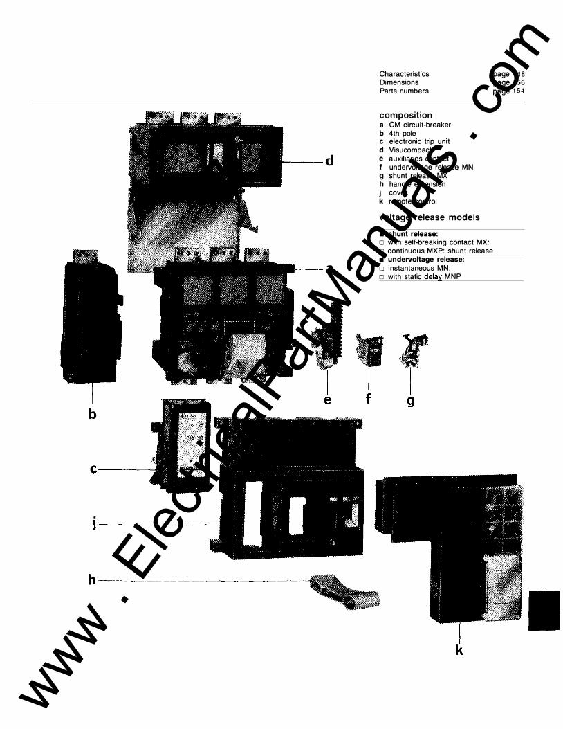
Characteristics page 1 48 Dimensions page 1 56
Parts numbers page 1 54
composition a CM circuit-breaker b 4th pole c electronic trip unit d Visucompact
d e auxiliaries contact f undervoltage release MN g shunt release MX h handle extension j cover k remote control
voltage release models
• shunt release: o with self-breaking contact MX: o continuous MXP: shunt release • undervoltage release:
a o instantaneous MN: o with static delay MNP
f b
. ]--------
k
www . El
ectric
alPar
tMan
uals
. com

Compact CM electrical characteristics
Compact type CM1250 CM1250H CM1600 · CM1600H rated current 40 oc 1 250 1 250 1 600 1 600
45 oc 1 250 1250 1 540 1 540 50 oc 1 250 1 250 1 470 1 470 55 oc 1 250 1 250 1 400 1 400 60 oc 1 250 1 250 1 330 1 330
rated voltage (V) AC 660 660 660 660 dielectric te11t voltage (V) AC 3000 3000 3000 3000
CM2000 2000 1 930 1 840 1 750 1 660 660 3000
Dimensions Part numbers Presentation
CM2000H CM2500 2000 2500 1 930 241 0 1 840 231 0 1 750 2200 1 660 2075 660 660 3000 3000
CM2500H 2500 241 0 231 0 2200 2075 660 3000
CM3200 3200 3 1 00 3000
page 1 56
page 1 54
page 1 44
CM3200H 3200 3100 3000
2800 2800 2700
· !----'-"----2700
660 ·--
660 --3000 3000
2500 for auxiliary circuits (do not carry out a dielectric test on the STCM trip unit) number of poles 3,4 3,4 3,4 3,4 3,4 3.4 3,4 3,4 3 3 4th pole rating (A) 1 250 1250 1 250 1 250 1 250 1 250 1 250 1 250 breaking capacity 220/240 v 85 1 25 85 1 25 85 1 25 85 1 25 85 85 (kA rms) in AC 380/415 v 70 85 70 85 70 85 70 85 70 85 IEC-P1 --UTE-P1 440 v 50 85 50 85 50 85 50 85 50 85
VDE-1"-K;! 500 v 50 50 50 50 50 50 50 50 50 50 BS 4752-P1 600 v 50 50 50 50 50 50 50 50 50 50
660 v 50 50 50 50 50 50 50 50 50 50 - - ----NEMA 240 v 85 1 25 85 1 25 85 1 25 85 1 25 85 1 25
480 v 65 85 65 85 65 85 65 85 65 85 600 v 50 50 50 50 50 50 50 50 50 50
making capacity 380 v 1 50 1 87 1 50 1 87 1 50 1 87 1 50 1 87 1 50 1 87 (kA peak) in AC 440 v 1 1 0 1 87 1 1 0 1 87 1 1 0 1 87 1 1 0 1 87 1 1 0 1 87
500 v 1 1 0 1 1 0 1 1 0 1 1 0 1 1 0 1 1 0 1 1 0 1 1 0 1 1 0 1 1 0 600 v 1 1 0 1 1 0 1 1 0 1 1 0 1 1 0 1 1 0 1 1 0 1 1 0 1 1 0 1 1 0 660 v 1 1 0 1 1 0 1 1 0 1 1 0 1 1 0 1 1 0 1 1 0 1 10 1 1 0 1 1 0
three-phase power loss (W) circuit-breaker 2 10 2 10 330 330 390 390 525 525 700 700 Visucompact 300 300 480 480 540 540 750 750
maximum break time (ms) 50 50 50 50 50 50 50 50 50 50 endurance mechanical 1 0000 1 0000 1 0000 1 0000 1 0000 1 0000 1 0000 1 0000 1 0000 1 0000 (CO cycles) electrical at ln/380 V 2000 2000 2000 2000 2000 2000 2000 2000 2000 2000 weight (kg) 3P 41 41 41 41 46 46 63 63 83 83
4P 56 56 56 56 61 61 78 78 switch version electrodynamic withstand (kA) 65 65 65 65 . thermal withstand (3 s) (kA rms) I 32 32 32 32 weight (kg) 3P 37 42 59 79
--r--------4P 52 57 74
Visucompact version weight (kg) 3P 64 64 73 92
4P 86 86 95 1 1 4 degree of protection IP405 IP405 IP405 IP405 IP405 IP405 IP405 IP405 IP405 IP405 tropicalization ambient temperature 45 oc and 95 % relative humidity or ambient temperature 55 oc and relative humidity 80 %
solid state trip unit mounting on Compact CM
long time delay protection
short time delay and instantaneous protection(2)
earth fault protection
3P 4P, unprotected neutral 4P, protected neutral lr = in x . . . tripping between: lm = l r x . . . accuracy setting of time delay maximum resettable time (ms) maximum breaking time (ms) It = In x . . . accuracy setting of time delay maximum resettable time (ms) maximum breaking time (ms)
• •
0.5-0.6-0.7-0.8-0.9-1 1 .05 and 1 .25 lr 3-4-5-6 ± 20 % none 0 50
STCM2 • • • 0.5-0.6-0.7-0.8-0.9-1 1 .05 and 1 .25 l r 2-4-6-8 ± 1 5 % 0 A B C
. 0 35 1 25 225 50 1 20 220 330
STCM3 • (1) ---------
0.5·0.6-0. 7·0.8-0.9-1 1 .05 and 1 .25 l r 2·4-6-8 ± 1 5 % 0 A B c 0 35 125 225 50 1 20 220 330 0,2-0,3-0,4-0,5 ± 15 %(3)
0 0,1 0,2 0,3 0 1 35 235 345 1 30 230 340 460
( 1 ) For systems with distributed but unswitched neutral, a 4th sensor can be supplied separately or fitting according to installation instructions. The Statipact STCM3 cannot be fitted to the 3200A Compact CM or four-pole Compact CM. ��� �� � the <;:ompact CM circuit-breakers incorporate an instantaneous trinninn thrPc:hnlrl c:;p,t �t ':t l:; V A r ...... ., ; ,.., ,.,rl...la;�� ·- •1... - - - - · - - · = - - -
www . El
ectric
alPar
tMan
uals
. com

Compact CM Visucompact CM1 250 to 2500
presentation The Visucompact CM is a three or fourpole unit comprising: • a disconnector for visible break disconnection. • a fixed Compact CM circuit-breaker for control and protection against overcurrents. The disconnection function is carried out by high electro-dynamic withstand selfcompensated finger contacts, which make the electrical connection by direct engagement on the upstream side of the circuit-breaker. The position of the contacts can be seen directly through a transparent screen. A pretipping system prevents on-load disconnection. The disconnector is always fitted with an "open" position padlocking device for 3 padlocks (not supplied). The Visucompact CM complies with the standards: C 1 3- 100 on consumer sub-stations. C 1 5-100 on electrical installation operation and maintenance.
i nstallation The Visucompact CM is delivered in three separate elements: • a disconnector mounted on a mounting plate • a fixed Compact CM circuit-breaker • the fitting accessories. The disconnector mounting plate is provided with guides to make circuitbreaker installation easier. The electrical connection between the two units being by means of the high-pressure finger contacts, the circuit-breaker can easily be disconnected after the downstream connections have been removed.
characteristics Disconnector characteristics are at least equivalent to those of circuit-breakers on which they are used . The Visucompact CM therefore offers the same performances as the Compact CM (3l _
Visucompact type CM1250 to CM2500 rated voltage 660 V AC number of poles 3 or 4 The other characteristics are identical to those of the Compact CM.
Dimensions Part numbers
electrical auxi l iaries, accessories and locking devices
page 1 57 page 1 54
All the Compact CM auxiliaries can be fitted to the Visucompact CM. Moreover, the disconnector can accept: • 1 unit of 2 auxiliary contacts(1 l_ • a device for locking in "open" position by Profalux 824-04-Z key-lock (lock supplied)(2l . • a door interlock (the door can only be opened if the disconnector is open).
(1 ) Changeover type with common point. Characteristics identical to those of the Compact CM OF contact. (2) Key shape identical to the Profalux V1 1 -18 . On r.:.nr u:,,c;::t �nnic:. 1 ��1R tvne lock. Kev shaoe identical the
www . El
ectric
alPar
tMan
uals
. com

Compact CM remote control
presentation The remote control opens and closes the Comact CM from a distance on orders from push-buttons, changeover switches or relays. It is fitted to the front face of the CM1 250 and CM3200 circuit-breakers and the Visucompact. Like the Compact CM, the remote control does not require any maintenance.
description Equipped with gear motor, the remote control ensures charging of operating mechanism and closing of the circuitbreaker in the same cycle. • remote opening is carried out by the MX shunt release or the MN or MNR undervoltage release. • local opening is carried out by a pushbutton.
electrical characteristics Compact type supply voltage (A) AC
DC consumption on closing AC (all voltages)
DC (all voltages) reponse time (under Un)
The state of the circuit-breaker is given by an indicator: • white: circuit-breaker closed. • green: circuit-breaker open. These two indicators give a positive break indication. A handle fitted on the front face enables the circuit-breaker to be operated locally. When local operation takes place, the remote electrical closing orders are locked.
use • remote control and protection of circuits with a low operating rate; • daily opening and closing of a circuit from a control desk; • non-priority circuit load-shedding and restoring control.
Compact CM1250 to CM3200 50 Hz 48 1 1 0 60 Hz 1 20 1 27
24 30 VA 700 w 700 closing: T < 1 .5 s opening: circuit-breaker opening time
1 27 240 48
Dimensions Part numbers Wiring diagram
installation
page 1 57 page 1 55 page 1 52
The remote control can be installad on the whole range of Compact CM circuitbreakers having either a shunt trip unit (MX) or an undervoltage release unit (MN). It is fitted to the front of the circuitbreaker<1 ).
220 240 380 415 265 277 440 480 1 00 1 1 0 1 25 220
�op!"e�r�at�in�g�li�m�it�s---==--
---------_:_VO�I'-'ta�g'c:e'-: 0"-'.c;-_85-:.__,tO:c__-_1 ·-.:.1_,U:o:n..___,at._4-'-'0._0_,C::__ ____________ ��-�-----�----endurance CO cycles (IEC) 10 000 max operating rate 2 cycles per minute fault contact (SDE) •
www . El
ectric
alPar
tMan
uals
. com

Compact CM electrical auxil iaries and accessories
insta l lation of auxi l iaries
auxi l ia ry contacts
4 OF + SO unit
voltage releases
Shunt tr ip unit (MX)
Undervoltage release unit (MN)
1
2
Auxiliaries can be easily fitted without adjustment by means of 2 fixing screws. Each auxiliary unit has a precabled connection terminal (except the SDE
• 1 unit including 2 OF contacts of changeover type with common point to indicate open or closed; • 1 unit including 4 OF contacts of changeover type with common point to indicate open or closed, associated with an SD contact of changeover type with common point which indicates the circuitbreaker discharged position following tripping either by the static trip unit or by the voltage release units; • 1 SDE contact (electrical fault signal), a closing contact which indicates circuitbreaker discharged position following tripping by the static trip unit only. This contact cannot be fitted in Compact CM load break switches.
Fitting possibilities Whatever the type of Compact CM, its rating and the number of poles, only one voltage release can be fitted per circuitbreaker, either: • an undervoltage relese o instantaneous (MN),
Electrical characteristics supply voltage see page 1 55
Part numbers Wiring diagram
page 1 55 page 1 52
contact which has to be wired to 2 separate terminals supplied). This terminal is accessible from the front without removing the cover.
Fitting possibilities In addition to the voltage release, each circuit-breaker can accept auxiliary contacts in the combinations given below:
OF 2 4 4
so SOE
Electrical characteristics auxiliaries t}'�e OF rated current (A) 2 breaking AC 240V 6 capacity 480V 6
600V 3 DC 24V 3
48V 3 125V 0.5 250V 0.25
so 2 5 5 3 3 3 0.5 0.25
o delayed action by static time delay (MNR); • or a shunt trip o with self-breaking contact (MX),
SOE 2 2
2 1 .2 0.4 0.2
o continuous (MXP), A derivative of the MX trip unit, it can remain continuously under voltage to prevent closing.
undervoltage release unit
operation between 0.35 and 0.7 Un
instantaneous (MN) time delayed (MNR)
shunt trip unit self-breaking (MX)
shunt trip unit continuous (MXP)(1 )
consumption (all voltages) inrush AC (VA) 200 DC (W) 45
opening time 50 ms
hold 80 3
accessories: static time delay set from 0.5 to 1 s operation between 0.7 and 1 . 1 Un consumption (all voltages) inrush
AC (VA) 1 1 0 DC (W) 1 20
opening time 50 ms operation between 0. 7 and 1 . 1 Un consumption (all voltages) inrush
AC (VA) 200 DC (W) 45
opening time 50 ms
hold 80 3
(1 ) a derivative of the MN trip unit, it can remain continuously under voltage while preventing closing.
On i l lustration opposite: 1 - key-lock 2 - padlock device
The following locking devices can be supplied on request: • open position padlocking device (padlock not supplied). • a device for locking in open position by Profalux KS5B24 key-lock supplied, key shape identical to Profalux V1 1 - 18. On request, Ranis N2070 type lock, key shape identical to Ron is 1 1 04 or EL 1 1 AP. www .
Elec
tricalP
artM
anua
ls . c
om

Compact CM wiring diagrams
Wiring diagram with: remote control right-hand terminal block
h L l Remote control
terminal block
Lett-hand terminal block
s� 'L.IID--·-
used for internal operation of remote control
manual control right-hand terminal block
Voltage releases
�MN �MNR �MX �NIXP
XR connection terminals K self-supply relay MX shunt release with self-breaking contact MN undervoltage release MXP continuous shunt release M electrical operating mechanism motor M2 cover opening interlock QF CM circuit-breaker BPO opening pushbutton YS fault trip lock-out and reset SDE fault trip indication XR connection terminals R additional resistance for U > 220 V AC or DC
diagram no. 698596 for local manual reset
"-T .., I I I I I I I I I I
' $ $ 1 I I
1 2 1 1 41 22
- - MX
J.+-.---1-4-4--4-4�1--1-+--- MN
- � - BPO
www . El
ectric
alPar
tMan
uals
. com

Compact CM connection
Compact CM connection For the 1 250, 1 600 and 2000A ratings, the equipment is supplied with bare terminals. A set of orientable connectors can be supplied on option. The bars can then the fitted in all the usual directions.
1 250-1 600-2000A ratings
Horizontal or vertical flat bars on bare terminals.
3200A rating
Horizontal edgewise bars with connectors.
Horizontal or vertical edgewise bars with connectors.
Visucompact CM connection
For the 2500A rating, the disconnector is always supplied with a set of orientable connectors per phase. These connectors must be used to connect the bars. However, the neutral terminal is supplied bare. A set of connectors can be supplied for this terminal as an optional extra.
2500A rating
Horizontal flat bars with connectors.
Vertical edgewise bars with connectors.
The method of connection to the (upstream) disconnector terminals is the same as for the Compact CM. Only the distance between fixing centres and the dimensions of the terminal differ (see overall dimensions). The connectors are the same as for the Compact CM, and the bar orientation and arrangement possibilities are the same. As for the Compact CM, the 2500A rating must be connected by means of the connectors supplied with the equipment.
For the 3200A rating, the basic circuitbreaker includes connectors enabling connection to be made by means of horizontal edgewise bars.
Horizontal edgewise bars with connectors.
Vertical edgewise bars with connectors.
www . El
ectric
alPar
tMan
uals
. com

Compact CM CM1 600 to CM3200
Compact CM
Compact CM1 250 fixed t-FC
Compact CM1 600 fixed j FC
Compact CM2000 fixed j FC
Compact CM2500 fixed t-FC
Compact CM3200 fixed j FC
Compact CM type H
Compact CM1 250H fixed j FC
Compact CM1 600H fixed j FC
Compact CM2000H fixed j FC
Compact CM2500H fixed j FC
Compact CM3200H fixed j FC
Visucompact CM
Visucompact CM1 250 fixed j FC
Visucompact CM1 600 fixed
j FC
Visucompact CM2000 fixed
t-FC
Visucompact CM2500 fixed j FC
Compact CM switches
Compact CM1 6001 fixed j FC
Compact CM20001 fixed j FC
Compact CM25001 fixed
� FC
Compact CM32001 fixed j FC
trip unit
STCM1 STCM2 STCM3 STCM1 STCM2 STCM3 STCM1 STCM2 STCM3 STCM1 STCM2 STCM3 STCM1 STCM2
trip unit
STCM1 STCM2 STCM3 STCM1 STCM2 STCM3 STCM1 STCM2 STCM3 STCM1 STCM2 STCM3 STCM1 STCM2
trip unit
STCM1 STCM2 STCM3 STCM1 STCM2 STCM3 STCM1 STCM2 STCM3 STCM1 STCM2 STCM3
rating (A)
1 600
2000
2500
3200
3P 4P 3t 3t 4t
55400 55406 5541 1 55417 55427 55401 55407 55412 55418 55428 55402 55408 55413 55419 55429 55403 55409 55414 55420 55430 55405 55416
3P 4P 3t 3t 4t
55433 55439 55444 55450 55460 55434 55440 55445 55451 55461 55435 55441 55446 55452 55462 55436 55442 55447 55453 55463 55438 55449
3P 4P 3t 3t 4t
55466 55470 55474 55478 55486 55467 55471 55475 55479 55487 55468 55472 55476 55480 55488 55469 55473 55477 55481 55489
3P 4P
55490 55494
55491 55495
55492 55496
55493
31 + N/2
55422
55423
55424
55425
3t + N/2
55455
55456
55457
55458
3t + N/2
55482
55483
55484
55485
Compact CM mccb's Visucompact CM Compact CM type I switches
Auxiliaries and accessories opposite page Characteristics page 1 48 Dimensions, tripping curves pages 1 56-1 58 Presentation page 1 44
4th earth fault protection sensor (fitted outside the circuit-breaker, with STCM3 only)
1 250 A 55528
1 600 A 55529
2000 A 55530
2500 A 55531
4th earth fault protection sensor (fitted outside the circuit-breaker, with STCM3 only)
1 250 A 55528
1 600 A 55529
2000 A 55530
2500 A 55531
4th earth fault protection sensor (fitted outside the circuit-breaker, with STCM3 only)
1 250 A 55528
1 600 A 55529
2000 A 55530
2500 A 55531
www . El
ectric
alPar
tMan
uals
. com

electrical auxi l iaries auxiliary switches
for Compact CM 2 OF 55541 4 0F + 1 SD 55542 for Visucompact CM 2 OF 55543 for remote control 4 OF (supplied with remote control)
55676
voltage releases (for remote tripping)
lin
MX (shunt trip) AC 50 Hz (V) AC 60 Hz (V) 48 55546 1 20/127 55547 _1 1_0_/1_2_7 _5_55_4_7 =-24C-'0:"/2=:6=-=5'----'"55:-c5=-4=-=8 208/220 55548 -'-44-'-'0"--/4'-=8"-0 ___,5'-=5�55=-=0 /240
380/415 55549 ------440 55550 DC (V) __
24 55544 30 55545 48 55546 1 1 0/1 25 55547 220 55548 MXP (continuous current shunt trip) AC 50 Hz (V) AC 60 Hz (V) 48 55693 1 20 55592 1 1 0 55586 1 27 55586 1 27 55587 240 55593 220 55588 265 55588 240 55589 277 55594 380/415 55591 440 55595
480 55591 DC (V) 24 55597 30 55598 48 55599 60 55697 1 1 0 55600 1 25 55601 220 55602 MN (instantaneous undervoltage release)
AC 50 Hz (V) AC 60 Hz (V) 48 55681 1 20 55558 1 1 0 55552 1 27 55552 1 27 55553 240 55559 220 55554 265 55554 240 55555 277 55560 380/415 55557 440 55561
480 55557 DC (V) 24 55563 30 55564 48 55565 60 55685 1 1 0 55566 1 25 55567 220 55568
MNR (time delayed undervoltage release)
AC 50 Hz (V) AC 60 Hz (V) 48 55687 1 20/1 27 55570 1 1 0 55569 240 55572 1 20/127 55570 440 55578 208/220 55571 240 55572 380 55573 415 55574 DC (V) 24 55580 30 55581 48 55582 1 1 0 55583 1 25 55584 220 55585
AC 50 Hz (V) AC 60 Hz (V) 48 55603 1 20/127 55611 1 1 0 55604 240 55613 1 27 55605 265 55614 220/240 55607 277 55615 380 55609 440 55616 415 55610 480 55617 DC (V) __
24/30 55618 48 55620 60 55621 1 00 55622 1 1 0 55623 1 25 55624 220 55625
accessories locking by padlocks or key lock
� for Compact CM for 3 padlocks (not supplied) 55653 for 3 padlocks (not supplied) 55654 + 1 Profalux 824D4Z
for 3 padlocks (not supplied) 55655 + 1 Ronis type 1 351 8
for Visucompact CM on disconnector (2)
for 3 padlocks (not supplied) 1 Profalux 824D4Z 55657 1 Ronis type 1 351 8 55658 1 door lock 55659
sealing accessory transparent sealable shield 55652 for Statipact STCM trip units
dummy trip unit (supplied with Compact CM switch)
-----fo_r_Co __ m_p_a_ct-C�M-s-w-it-ch ______ 55_5_3_5 1 250 to 3200A
testing kit for Statipact STCM2 and STCM3 (1 1 0-1 27-220-240V CA) 55651
connection for Compact CM and Visucompact CM
phase or neutral connector for � Compact CM ,; 2000A or neutral iUJJ connector for Compact CM
,;2500A 1 connector 55660
auxiliaries, accessories connection, spare parts
www . El
ectric
alPar
tMan
uals
. com

Compact CM dimensions
Compact CM1 250 to 2500
Approximate weights (kg) without accessories or auxiliaries rating 1 250 1600 2000 3-pole 41 41 46 4-pole 56 56 61
Terminal pads All ratings
2500 63 78
N.B.: any busbar passing over blowing openings will have to be insulated.
Connection Compact CM1 250 to 2000 (1 )
fao
� j155 j1201120j-
''"�- - . I ' I � I I
55
i -1-105 t- --
Bare terminals for horizontal or vertical flat bars.·
Terminals with connectors for horizontal or vertical edgewise bars.
1 250 to 2000A connectors (1 )
Compact CM3200
Approximate weight: 83 kg The dimensions of the Compact CM3200 are identical to those of the Compact CM1 250 to 2500 except for the terminal pads.
Compact CM2500 (2)
c c c; j135f140t140j-o ii' 20-lt- I ""tf-20 I ! �· 105 -
r.fl., j .
-
f.l, .L � 1 I 75 I . -Terminals with connectors for horizontal flat bars.
2500A connectors (2)
Phases 1 and 3 RH upstream or LH downstream
-1�5 -:- -c
1 ,5 l'l11 Jr�40 _t{_�
C : busbar fixing axis
Compact CM1 250 to 3200
-L 1ss--L120 + 120� 89 - ·
c c c j135t140t14o+- 1is 1r���20 60 -
. ' -l-rr+·l ' . .. 115. .
i t ' ' t --Terminals with connectors for vertical flat bars.
LH upstream or RH downstream
j155-r20f120t- 55i '� .f.. '
• 105 ! . I t t ·
Terminals with connectors for lforizontal or vertical edgewise bars.
Central phase
i-- 120+ 1?0--j tt----- 390 ----tl
550
+
25 - f 2s�fs�-12
I '-'-f---'"--12L, 5 : ' 12 5 20 .
_:� 45
www . El
ectric
alPar
tMan
uals
. com

Visucompact CM1 250 to 2500
Approximative weights (kg) without accessories or auxiliaries rating 1 250 1 600 2000 2500 3-pole 64 64 73 92 4-pole 86 86 95 1 1 4
Upstream terminal pads
rating a b ,; 1 600 1 20 1 50 2000 1 30 1 40 2500 130 140
e = 80 for 1 250 and 1600 ratings e = 1 00 for 2000 and 2500 ratings
Upstream connection. The downstream connection is identical to the Compact CM (see opposite). Visucompact CM1 250 to 2000 <1 1 . Visucompact CM2500 (2)
Bare terminals for horizontal or vertical flat bars.
Terminals with connectors for horizontal or vertical edgewise bars.
remote control for Compact CM1 250 to 3200
(1) For the 1 250 to 2000A ratings, the connectors are
Terminals with connectors for horizontal flat bars.
16
330 r I c:--1 i I I L
Visucompact CM1 250 to 2500
-------!
- ... . . . . •' ,, " l L• • .. I I I
r - �s:::;D�363' 653 : : 579 I
1 1 763
c c
I I : I. I I I I
"1120j'1�150f-' 11 20--i:"' i -ii-'20 60 ,A:t �..-� 1k
i � t- -Terminals with connectors for vertical flat bars.
"i140,00,130r
·�·· · - ·· r -: I I I + I
Terminals with connectors for horizontal or vertical edgewise bars.
C : busbar fixing axis
22
www . El
ectric
alPar
tMan
uals
. com

Compact CM tripping curves
STCM1
, t t fH �f+�' l'f ' c j 1- 'x ' t ' l'f�W
· -ocin 't � .
. �� , ,.f' , t" r�t , . . .. .,. 't"; .,. ::tt:;' , �·· ,,,
tc .' + .g'�i-f£ t 1= FI'cl ' - " �J:t rJ ' ' '
(1) long time delay protection (overloads). (2) instantaneous protection (short-circuits).
STCM2 and STCM3 10000 5000 1h· 2000 1000 500 200 100
50
20 10
1 05 02
.1 005 002 00 1
0005 0002 000 1
tis!
'\. '\
05
1
,[', ' '
'
'1 3�-JC lo/, 11
' 4
2 3 4 5 6 78 10 20 30 50 70 100 200 1/lr (3) short t1me delay protection (short-c"cu1ts), with t1me delay settings. (4) instantaneous 35 kA (shown for the 2500A rating).
STCM3 10000 t(s) 5000 I ' 1h-- ' 2000 1000 ' I .
- : I 500
200 Jl 100
05 ' I 02 - ;
earth protection
TT'
::"
i
i . ·.· l i ' ' " '
! , ' � · _ -_; ,_ '-:j_ " _ _,_ _ _
�+ c1lf-i.' 'l,... ; 'icc': ; r+ lfi �� 6 •'-t ' .P"lt�', · l:i:'r.=\. • J::t & · EF
0,05 OJ G_2 0.4 Q50} 1 2 3 5 7 10 201/ln
(5) earth fault protection. (6) time delay settings for earth protection.
www . El
ectric
alPar
tMan
uals
. com

www . El
ectric
alPar
tMan
uals
. com

MERLIN GERIN 38050 Grenoble cedex France tel. : 76 57 60 60
As standards, specifications and designs develop from time to time, always ask for confirmation of the information given in this publication. www .
Elec
tricalP
artM
anua
ls . c
om