LMProPower - shop.next2vet.se · This scaler is designed for dental purposes. It is designed for...
36
USER MANUAL LMProPower UltraLED USER MANUAL
Transcript of LMProPower - shop.next2vet.se · This scaler is designed for dental purposes. It is designed for...
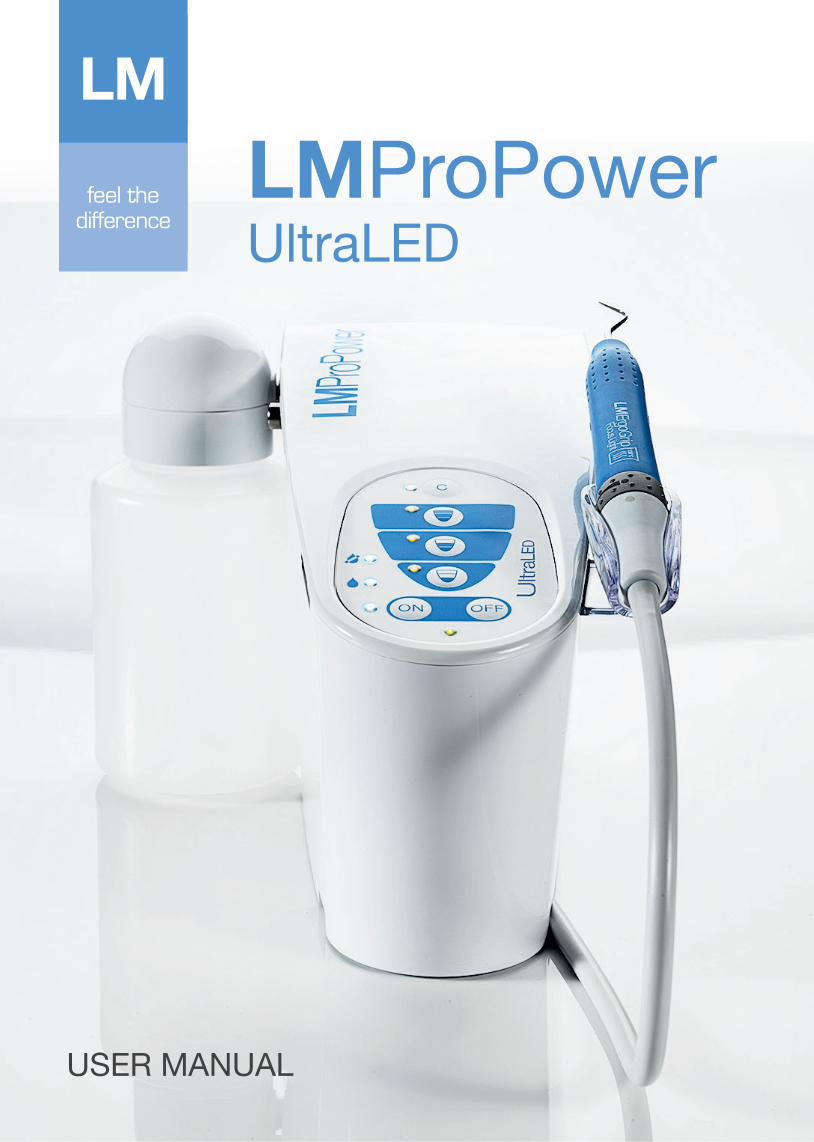
USER MANUAL
LMProPowerUltraLED
USER MANUAL
This manual is valid for:LM-ProPower 100721741 LM-ProPower 100731751LM-ProPower 100721741usLM-ProPower 100731751usLM-ProPower 100721741jpLM-ProPower 100731751jp Important!Read this manual carefully before using the product.
How to read this manualEach chapter starts with a section with general instructions, which is followed by sections with additional information. First read the general section and then proceed to the section that applies to your product. If there are any questions regarding the contents of this manual, please contact LM-Instruments Oy.
Manufacturer, Marketing and SalesLM-Instruments OyPL 88 (Norrbyn rantatie 8)FI-21601 Parainen. FinlandTelephone: +358 2 4546 400Fax: +358 2 4546 444E-mail: [email protected]: www.lm-dental.com
CopyrightCopyright 2014 LM-Instruments Oy. All rights reserved. The contents of this manual may be changed without notice. No part of this manual may be reproduced in any form or by any means without permission in writing from LM-Instruments Oy.
0537
2
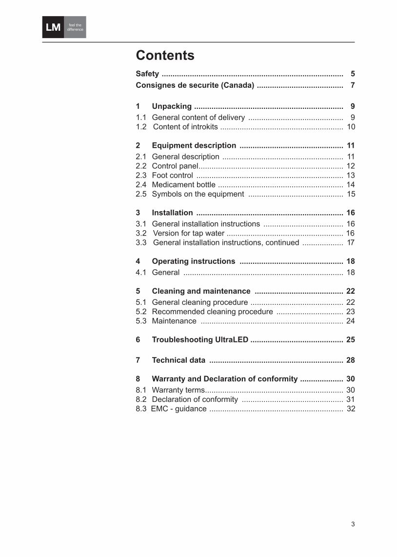
ContentsSafety .................................................................................... 5Consignes de securite (Canada) ........................................ 7
1 Unpacking ..................................................................... 91.1 General content of delivery ............................................ 9 1.2 Content of introkits ......................................................... 10
2 Equipment description ................................................ 112.1 General description ........................................................ 112.2 Control panel ................................................................... 122.3 Foot control .................................................................... 132.4 Medicament bottle .......................................................... 142.5 Symbols on the equipment ............................................ 15
3 Installation .................................................................... 163.1 General installation instructions ..................................... 163.2 Version for tap water ...................................................... 16 3.3 General installation instructions, continued ................... 17
4 Operating instructions ................................................ 184.1 General .......................................................................... 18
5 Cleaning and maintenance ......................................... 225.1 General cleaning procedure ........................................... 22 5.2 Recommended cleaning procedure ............................... 235.3 Maintenance .................................................................. 24
6 Troubleshooting UltraLED ........................................... 25
7 Technical data .............................................................. 28
8 Warranty and Declaration of conformity .................... 308.1 Warranty terms ................................................................ 30 8.2 Declaration of conformity ............................................... 31 8.3 EMC - guidance .............................................................. 32
3

4
5
SafetyIntended useThis scaler is designed for dental purposes. It is designed for removal of tartar or calculus on teeth and other dental work where the ultrasonic vibration is beneficial. The unit should only be used by licensed dental proffesionals trained in the proper use of scaling devices. Do not use it for applications where it is not intended. If you are unsure about your application, please contact your local dealer or place of purchase.
General requirementsService of the product is only to be performed by authorized service personnel.The product must be connected to electricity- and water supply meeting the requirements specified in the Technical data section page 28.The product needs special precautions regarding EMC (Elektro Magnetic Compability) and needs to be installed and put into service according to the EMC information provided on page 33. Portable and mobile RF (Radio Frequency) communications equip-ment can affect the product.
ContraindicationsDo not use the scaler on patients with cardiac pacemakers. The scaler may disturb the function of the pacemaker.
General precautions • The product is not suitable for use in the presence of flammable gases.• Only use the product in combination with LM-Instruments and Amdent scaler tips.• If the handpiece tubing is damaged or worn-out, it must immedia- tely be replaced to avoid exposing the user or the patient to elec- tric hazard.• Use the original packaging when returning equipment for service.
WarningsThe product should not be used adjacent to or stacked with other equipment. If adjacent or stacked use is necessary, the product should be observ-ed to verify normal operation in the configuration in which it will be used.
Safety

66
WARNING
Caution
Note
Safety notices in this manual
Warning indicates a potentially dange-rous situation. Non-observance may lead to death or injury.
Caution indicates a potentially harmful situation. Non-observance may damage the equipment.
Note indicates a situation where special notice should be observed.
Safety

7
Consigne de sécurité (Canada)Utilisation prévueCet appareil à ultrasons est destiné à des applications dentaires. Il est conçu pour éliminer le tartre ou les calculs des dents et pour toute autre application dentaire où les vibrations ultrasonores sont bénéfiques. Cet appareil doit être exclusivement manipulé par des professionnels dentaires diplômés ayant suivi une formation relative à l’utilisation correcte des dispositifs de détartrage. N’employez pas cet appareil pour des applications pour lesquelles il n’est pas conçu. Au cas où vous ne seriez pas sûr de son application, veuillez contacter votre distributeur local ou le point de vente.
Conditions généralesLe service du produit doit être executé seulement par le personnel de service autorisé avec les outils et le matériel appropriés. Le produit doit être relié à l’approvisionnement de l’électricité et à l’approvisionnement en eau répondant aux exigences définies dans la section Caractéristiques techniques à la page 28. Le produit exige des précautions spéciales concernant la CEM (Compatibilité Electromagnétique) et doit être installé et mis en service selon à la page 33. L’équipement de communication RF (Radio Fréquence) portable et mobile peut affecter le produit.
Contres-indicationN’employez pas sur des patients avec les stimulateurs cardiaques. Le produit peut déranger la fonction du stimulateur.
Précautions générales• Le produit n’est pas approprié pour l’usage en présence d’un mélange anesthésique inflammable. • Utilisez seulement le produit en combinaison avec des inserts de détartreur de LM-Instruments et Amdent. • Si la tuyauterie de pièce à main est endommagée ou usée, elle doit immédiatement être substituée pour éviter d’exposer l’utilisateur ou le patient au risque électrique. • Utilisez l’original empaquetage en renvoyant le matériel pour le service.
AvertissementLe produit ne doit pas être utilisé à proximité ou empilé avec d’autres équipements. Si l’usage adjacent ou empilé est nécessaire, le produit doit être surveillé pour une utilisation normale suivant la configuration dans laquelle il sera utilisé.
Consigne de sécurité

Notifications de sûreté en ce manuel
“Warning” indique une situation proba-blement dangereuse. La inobservance peut mener à la mort ou des dommages.
“Caution” indique une situation probable-ment nocive. La inobservance peut endom-mager le matériel.
“Note” décrit si on observe la notification spéciale.
8
Consigne de sécurité
6
WARNING
Caution
Note

Carefully unpack your LM-ProPower UltraLED unit and verify that all accessories and components are included according to the content lists below:
1.1 General content of delivery
1 Unpacking
Note
This chapter describes the components of the delivery and can be used as a check list when unpacking. Con-tact your place of purchase if anything is missing. For a description of the features of the equipment, read the Equipment description sec-tion on page 11.
6
Safety notices in this manual
Warning indicates a potentially dangerous situation. Non-observ-ance may lead to death or injury.
Caution indicates a potentially harmful situation. Non-observ-ance may damage the equipment.
Note indicates a situation where special notice should be ob-served.
WARNING
Caution
Note
9
Unpacking
1. LM-ProPower UltraLED unit
2. Scaler handpiece connected to unit
3. Scaler introkit (see section 1.2 )
4. 500 ml medicament bottle or water hose 6 mm (1/4”)
5. Foot control
6. Foot control cable
7. Power cord
8. LM-ProPower Fixer
7
2
3
4
1
6
8
5

10
1.2 Content of introkitsContent of UltraLED Scaler introkit3 x Scaler tips 3 x ErgoGrips 3 x Torque Wrenches3 x Tip Check Cards
Unpacking

11
2 Equipment description2.1 General descriptionLM-ProPower UltraLED is an effective piezoelectric scaler in a versatile and ergonomic appliance.
The device’s LED lights, advanced electronics, quality, and high-durability LM-DuraGradeMAX tips enhance the execution of procedures which require great precision.
Ergonomically designed ErgoGrip handpieces with soft silicone hand-les give the user a comfortable, relaxed grip as well as an excellent feel.
LM-ProPower is highly adaptable to any procedure or user approach. It is not only an outstanding scaling and cleaning device, but it also brings power and versatility to endodontics, implantology, restorative treatments, minimally invasive treatments and apical surgery.
Equipment description
1. UltraLED Handpiece (with an ErgoGrip and a tip mounted)
2. Water flow control ring
3. Handpiece tubing
4. Control panel
5. Foot control
6. Medicament bottle
7. Depressurisation button
1
6
5
2
4
3
7
12
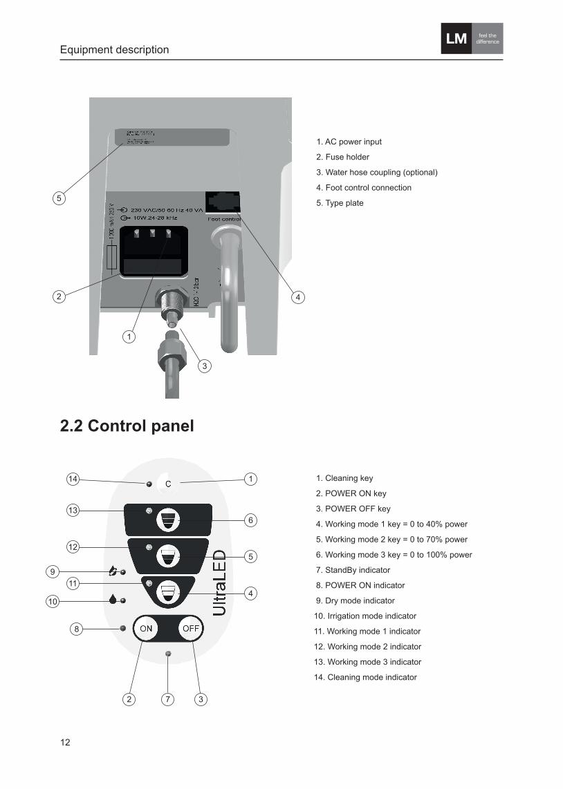
1. AC power input
2. Fuse holder
3. Water hose coupling (optional)
4. Foot control connection
5. Type plate
2.2 Control panel
1. Cleaning key
2. POWER ON key
3. POWER OFF key
4. Working mode 1 key = 0 to 40% power
5. Working mode 2 key = 0 to 70% power
6. Working mode 3 key = 0 to 100% power
7. StandBy indicator
8. POWER ON indicator
9. Dry mode indicator
10. Irrigation mode indicator
11. Working mode 1 indicator
12. Working mode 2 indicator
13. Working mode 3 indicator
14. Cleaning mode indicator
Equipment description
14
2 7 3
8
13
12
911
104
5
6
1
42
3
1
5
13
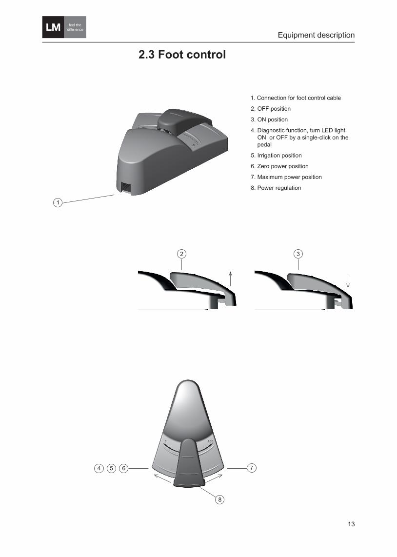
2.3 Foot control
11. Connection for foot control cable
12. OFF position
13. ON position
14. Diagnostic function, turn LED light ON or OFF by a single-click on the pedal
15. Irrigation position
16. Zero power position
17. Maximum power position
18. Power regulation
1
Equipment description
32
75 6
8
4
1

14
2.4 Medicament bottle (optional)LM-ProPower has a medicament dispenser system, making the device independent of a fixed water supply connection. The medicament bottle can be used for either medi-cament solutions or ordinary clean water.The unit contains an electrically driven air compressor. When operating the unit the compressed air forces the fluid from the bottle through the hose and to the handpiece and the tip/nozzle.
The LM-ProPower can be delivered either with the medicament dispenser system or with fixed water supply connection without the bottle and bottle connector.
Equipment description
2
1
1. Medicament bottle
2. Bottle connector
3. Depressurisation button
3

15
2.5 Symbols on the equipment Working mode 1 = 0 to 40% power
Working mode 2 = 0 to 70% power
Working mode 3 = 0 to 100% power
Irrigation mode
Dry mode
Automatic cleaning function
Power ON
Power OFF
Example of type plate. The type plate is placed on the back side of the scaler unit.
Caution
Consult accompanying documents.
Compliance label indicating compliance with the Medical Device Directive 93/42/EEC. 0537 is the ID-number of the Notified Body: VTT
Withstands autoclave temperature 135°C (275°F).
Type B applied part according to the degree of protection against electrical shock.
Fuse
Input
Output
Please do not throw the equipment into the domestic refuse. Please use the re-turn and collection systems available in your country for the disposal of this product. The equipment can also be returned to the manufacturer for disposal.
0537
Equipment description
CLASSIFIED
9800163
Medical electrical equipment classified by ETL with respect to electric shock, fire, mechanical, and other specified hazards in accordance with the Safety Standards ANSI/AAMI ES 60601-1 and CAN/CSA C22.2 No 60601-1:08
16
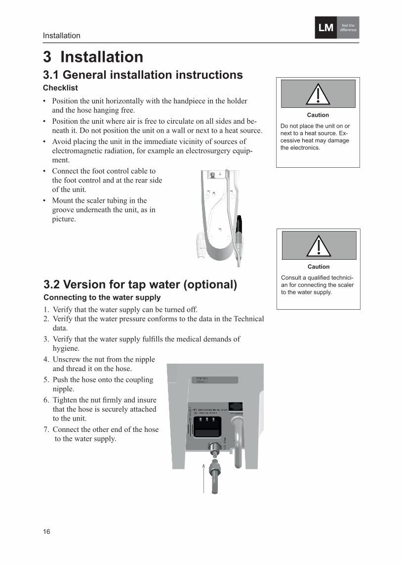
Caution
Do not place the unit on or next to a heat source. Ex-cessive heat may damage the electronics.
Caution
Consult a qualified technici-an for connecting the scaler to the water supply.
Installation
6
WARNING
Caution
Note
6
WARNING
Caution
Note
3 Installation3.1 General installation instructionsChecklist• Position the unit horizontally with the handpiece in the holder
and the hose hanging free.• Position the unit where air is free to circulate on all sides and be-
neath it. Do not position the unit on a wall or next to a heat source.• Avoid placing the unit in the immediate vicinity of sources of
electromagnetic radiation, for example an electrosurgery equip-ment.
• Connect the foot control cable to the foot control and at the rear side of the unit.
• Mount the scaler tubing in the groove underneath the unit, as in picture.
3.2 Version for tap water (optional)Connecting to the water supply1. Verify that the water supply can be turned off. 2. Verify that the water pressure conforms to the data in the Technical
data.3. Verify that the water supply fulfills the medical demands of
hygiene.4. Unscrew the nut from the nipple
and thread it on the hose.5. Push the hose onto the coupling
nipple.6. Tighten the nut firmly and insure
that the hose is securely attached to the unit.
7. Connect the other end of the hose to the water supply.
17
WARNING
The unit must be connec-ted to an AC power outlet provided with a protective ground. USA and Canada: The power cord and plug must be classified as ”Hos-pital-Grade”.
6
Safety notices in this manual
Warning indicates a potentially dangerous situation. Non-observ-ance may lead to death or injury.
Caution indicates a potentially harmful situation. Non-observ-ance may damage the equipment.
Note indicates a situation where special notice should be ob-served.
WARNING
Caution
Note
Installation
• Verify that the voltage rating on the rear side match the voltage of the AC power outlet.
• Verify that the AC power outlet is provided with a protective ground.
• Connect the power cord to the unit and the AC power outlet. All indicator lamps will illuminate for a short period during a self check of the unit.
• The unit is standby when the green indicator lamp is illuminated.
3.3 General installation instructions, continued

18
Operating instructions
4 Operating instructionsPreparations (bottle version)1. Fill the medicament bottle with water or medicament solution
according to the Medicaments that can be used, listed on page 29.
2. Screw the bottle connector onto the bottle and push it onto the con-nector. See picture in section 2.4
3. Check that the power cord is connected and the unit is in stand-by mode, the green indicator lamp is illuminated.
4.1 General1. Gently slide the ErgoGrip on to the scaler handpiece.
2. Carefully place the tip in the torque wrench.
3. Use the torque wrench and screw the tip clockwise on to the scaler handpiece. Tighten until resistance and the torque wrench slides. The torque wrench prevents the tip from being overtightened.
WARNING
A tip that is bent, altered, worn more than 2 mm will loose performance and must be exchanged. Prolonged use may cause tip breakage and injury to the patient.
The operator should be aware of that ultrasonic in-struments with small diame-ters are subject to breakage at any time. If not used cor-rectly or with too much po-wer or force the instrument WILL break.
Do not use nickel-titanium files, since they easily break at high frequenses.
6
Safety notices in this manual
Warning indicates a potentially dangerous situation. Non-observ-ance may lead to death or injury.
Caution indicates a potentially harmful situation. Non-observ-ance may damage the equipment.
Note indicates a situation where special notice should be ob-served.
WARNING
Caution
Note

19
10. Keep the patient’s lips, cheeks and tongue out of the way of the tip and perform treatment according to “How to use the scaler” section on next page.Note
At low power settings there will be no spray.
Increase the water flow if the handpiece feels too warm.
6
Safety notices in this manual
Warning indicates a potentially dangerous situation. Non-observ-ance may lead to death or injury.
Caution indicates a potentially harmful situation. Non-observ-ance may damage the equipment.
Note indicates a situation where special notice should be ob-served.
WARNING
Caution
Note
4. Turn on the UltraLED scaler by ON key on the keyboard. The blue indicator lamp illuminates and the scaler is activated.
5. The indicators next to the working modes are flashing to remind that a working mode has to be selected. If several blue indicators are flashing instead, check that the scaler hand piece is connected. If the problem remains concern the trouble shooting section. Check the re-commended working mode that is marked on the tip and choose the working mode by pressing the corresponding working mode key on the keyboard.
6. A second press of the “ON” key activates the dry mode for scaling without water/medicament.
7. A third press of the “ON” key activates the irrigation mode. The irrigation mode can also be activated in the scaling mode by pressing down the foot control in the leftmost position.
8. By pressing the “ON” key repeatedly, it will toggle between normal scaling, dry and irrigation mode.
9. Keep the handpiece over the cuspidor bowl and depress the foot control in the leftmost position and adjust the water flow with the ring on the handpiece until the water is dripping from handpiece as in picture below. Recommended flow: 20 ml/min.
WARNING
Remember to choose the right working mode if chang-ing scaler tip during the treatment
New tips are not sterile upon delivery. Sterilize before use according to the clinic’s routines.
Keep the patient’s lips, cheeks, and tongue out of the way of the activated tip, since contact may cause burns because of friction heat.
6
Safety notices in this manual
Warning indicates a potentially dangerous situation. Non-observ-ance may lead to death or injury.
Caution indicates a potentially harmful situation. Non-observ-ance may damage the equipment.
Note indicates a situation where special notice should be ob-served.
WARNING
Caution
Note
Operating instructions
Caution
Without cooling fluid, the maximum operating time, for the scaler handpiece, is 2 minutes followed by a cooling-down period of 8 minutes. Operating without cooling fluid for more than 2 minutes may cause over-heating of the scaler hand-piece.After above cycle has been repeated 2 times, the scaler handpiece has to cool down for at least 60 minutes.
6
WARNING
Caution
Note
20
Operating instructions
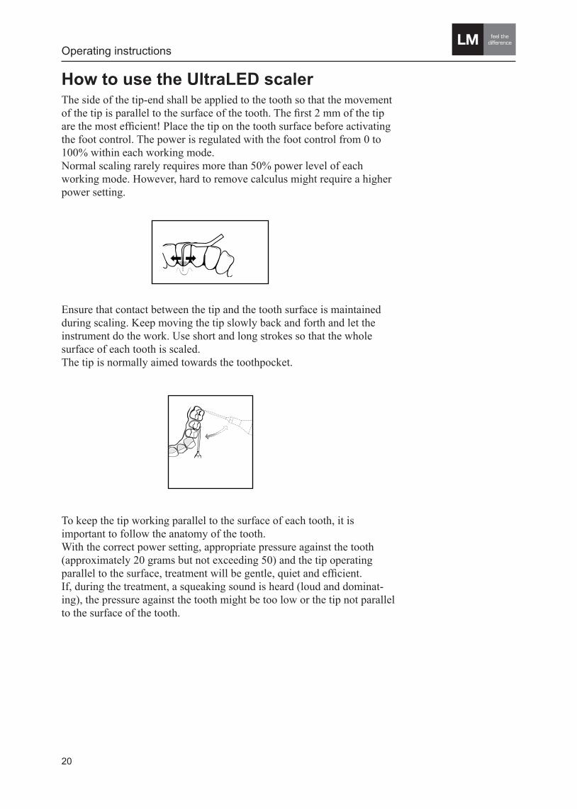
How to use the UltraLED scalerThe side of the tip-end shall be applied to the tooth so that the movement of the tip is parallel to the surface of the tooth. The first 2 mm of the tip are the most efficient! Place the tip on the tooth surface before activating the foot control. The power is regulated with the foot control from 0 to 100% within each working mode.Normal scaling rarely requires more than 50% power level of each working mode. However, hard to remove calculus might require a higher power setting.
Normal scaling rarely requires more than 50% power level. However, hard to remove calculus might require a higher power setting.
The tip is normally aimed towards the toothpocket.
With the correct power setting, appropriate pressure against the tooth (approx. 20 grams but not exceeding 50) and the tip operating parallel to the surface, treatment will be gentle, quiet and efficient.
If, during the treatment, a squeaking sound is heard (loud and dominating), the pressure against the tooth might be too low or the tip not parallel to the surface of the tooth.
To keep the tip working parallel to the surface of each tooth, it is important to follow the anatomy of the tooth.
How to use the scalerThe side of the tip-end shall be applied to the tooth so that the movement of the tip is parallel to the surface of the tooth. The first 2 mm of the tip are the most efficient! Place the tip on the tooth surface before activating the foot switch.
Ensure that contact between the tip and the tooth surface is maintained during scaling. Keep moving the tip slowly back and forth and let the instrument do the work. Use short and long strokes so that the whole surface of each tooth is scaled.
Ensure that contact between the tip and the tooth surface is maintained during scaling. Keep moving the tip slowly back and forth and let the instrument do the work. Use short and long strokes so that the whole surface of each tooth is scaled.The tip is normally aimed towards the toothpocket.
To keep the tip working parallel to the surface of each tooth, it is important to follow the anatomy of the tooth.With the correct power setting, appropriate pressure against the tooth (approximately 20 grams but not exceeding 50) and the tip operating parallel to the surface, treatment will be gentle, quiet and efficient.If, during the treatment, a squeaking sound is heard (loud and dominat-ing), the pressure against the tooth might be too low or the tip not parallel to the surface of the tooth.
21
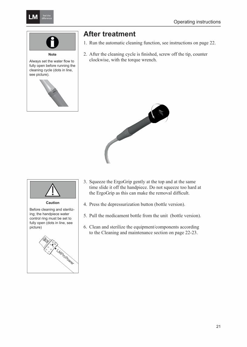
After treatment 1. Run the automatic cleaning function, see instructions on page 22.
2. After the cleaning cycle is finished, screw off the tip, counter clockwise, with the torque wrench.
3. Squeeze the ErgoGrip gently at the top and at the same time slide it off the handpiece. Do not squeeze too hard at the ErgoGrip as this can make the removal difficult.
4. Press the depressurization button (bottle version).
5. Pull the medicament bottle from the unit (bottle version).
6. Clean and sterilize the equipment/components according to the Cleaning and maintenance section on page 22-23.
Operating instructions
Caution
Before cleaning and steriliz- ing; the handpiece water control ring must be set to fully open (dots in line, see picture)
6
WARNING
Caution
Note
Note
Always set the water flow to fully open before running the cleaning cycle (dots in line, see picture).
6
Safety notices in this manual
Warning indicates a potentially dangerous situation. Non-observ-ance may lead to death or injury.
Caution indicates a potentially harmful situation. Non-observ-ance may damage the equipment.
Note indicates a situation where special notice should be ob-served.
WARNING
Caution
Note
22
Cleaning and maintenance
Note
Always set the water flow to fully open before running the cleaning cycle (dots in line, see picture).
6
Safety notices in this manual
Warning indicates a potentially dangerous situation. Non-observ-ance may lead to death or injury.
Caution indicates a potentially harmful situation. Non-observ-ance may damage the equipment.
Note indicates a situation where special notice should be ob-served.
WARNING
Caution
Note
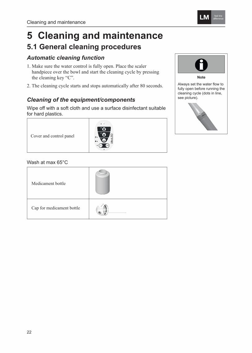
5 Cleaning and maintenance5.1 General cleaning proceduresAutomatic cleaning function1. Make sure the water control is fully open. Place the scaler handpiece over the bowl and start the cleaning cycle by pressing the cleaning key “C”.2. The cleaning cycle starts and stops automatically after 80 seconds.
Cover and control panel
Cleaning of the equipment/components Wipe off with a soft cloth and use a surface disinfectant suitable for hard plastics.
Wash at max 65°C
Medicament bottle
Cap for medicament bottle

23
Scaler tips
Torque wrenches
LM-ErgoGrip Focus LED
LM-ProPower scaler handpiece
Autoclave in steam at 134°C (max 135°C) for at least 3 minutes
Caution
Do not sterilize any scaler accessories using dry heat or chemical autoclaves. This may damage the material.
5.2 Recommended cleaning procedureBeginning of the day Run the automatic cleaning cycle with clean water. See instructions on page 22.
After each treatment• Run the automatic cleaning cycle with clean water. See instructions
on page 22.• Wipe off the cover, control panel, handpiece and the hose with a
soft cloth. Use a surface disinfectant suitable for hard plastics.• Wash the ErgoGrip, the tip and possibly the scaler handpiece and
autoclave according to the clinic’s routines.
End of the day• Run the automatic cleaning cycle with clean water. See instructions
on page 22.• Remove and wash medicament bottle and bottle cap at a maximum
temperature of 65°C (bottle version).
Cleaning and maintenance
6
WARNING
Caution
Note
Note
Autoclaving the handpiece regularly may shorten the life time of the scaler hand-piece.
6
Safety notices in this manual
Warning indicates a potentially dangerous situation. Non-observ-ance may lead to death or injury.
Caution indicates a potentially harmful situation. Non-observ-ance may damage the equipment.
Note indicates a situation where special notice should be ob-served.
WARNING
Caution
Note
6
WARNING
Caution
Note
Caution
Before cleaning and steriliz- ing; the handpiece water control ring must be set to fully open (dots in line, see picture)
Note
Always set the water flow to fully open before running the cleaning cycle (dots in line, see picture).
6
Safety notices in this manual
Warning indicates a potentially dangerous situation. Non-observ-ance may lead to death or injury.
Caution indicates a potentially harmful situation. Non-observ-ance may damage the equipment.
Note indicates a situation where special notice should be ob-served.
WARNING
Caution
Note

24
Cleaning and maintenance
5.3 MaintenancePower cord Inspect the power cord, cables and the handpiece hose daily to insure that the equipment is in good condition without mechanical damage.
O-rings (bottle connector) Lubricate the O-rings regularly with a glycerine based, water soluble lubricant. Vaseline may also be used, but it may shorten the durability time of the O-rings.
Tips When a tip is bent, altered, or worn more than 2 mm it will loose performance and must be exchanged. Check the tip length weekly by comparing the tip to a tip check card.
Exchanging fuses1. Disconnect the power cord from the AC power outlet and the unit.2. Open the fuse holder on the rear side of the unit.
Weekly (bottle version)• Run the automatic cleaning cycle with an anti-microbial cleaning
agent solution in the bottle. See instructions on page 22. We recommend to use a separate bottle for the cleaning agent solution. Concerning exposure times of cleaning agent, follow instructions given by manufacturer.
• Before patient treatment; to rinse the lines from cleaning agent solution put clean water in the bottle and run the automatic cleaning cycle until clean water comes out of the handpieces.
3. Inspect the fuses for damages. Replace damaged fuses with new ones. Verify the fuse specifications according to the Technical data section on page 28.
4. Close the fuse holder.
Caution
A petroleum based lubricant on the o-rings may shorten their durability time.
WARNING
A tip that is bent, altered, scratched or worn more than 2 mm will loose performan-ce and must be exchan-ged. Prolonged use may cause tip breakage and inju-ry to the patient.The opera-tor should be aware of that ultrasonic instruments with small diameters are subject to breakage at any time. If not used correctly or with too much power or force the instrument WILL break.
6
Safety notices in this manual
Warning indicates a potentially dangerous situation. Non-observ-ance may lead to death or injury.
Caution indicates a potentially harmful situation. Non-observ-ance may damage the equipment.
Note indicates a situation where special notice should be ob-served.
WARNING
Caution
Note
6
WARNING
Caution
Note
25
Troubleshooting
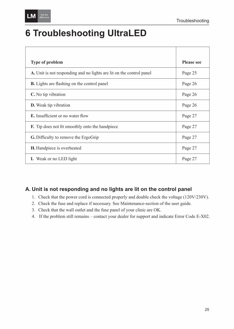
6 Troubleshooting UltraLED
A. Unit is not responding and no lights are lit on the control panel1. Check that the power cord is connected properly and double check the voltage (120V/230V).2. Check the fuse and replace if necessary. See Maintenance-section of the user guide.3. Check that the wall outlet and the fuse panel of your clinic are OK.
4. If the problem still remains – contact your dealer for support and indicate Error Code E-X02.
Type of problem Please see
A. Unit is not responding and no lights are lit on the control panel Page 25
B. Lights are flashing on the control panel Page 26
C. No tip vibration Page 26
D. Weak tip vibration Page 26
E. Insufficient or no water flow Page 27
F. Tip does not fit smoothly onto the handpiece Page 27
G. Difficulty to remove the ErgoGrip Page 27
H. Handpiece is overheated Page 27
I. Weak or no LED light Page 27
26
Troubleshooting
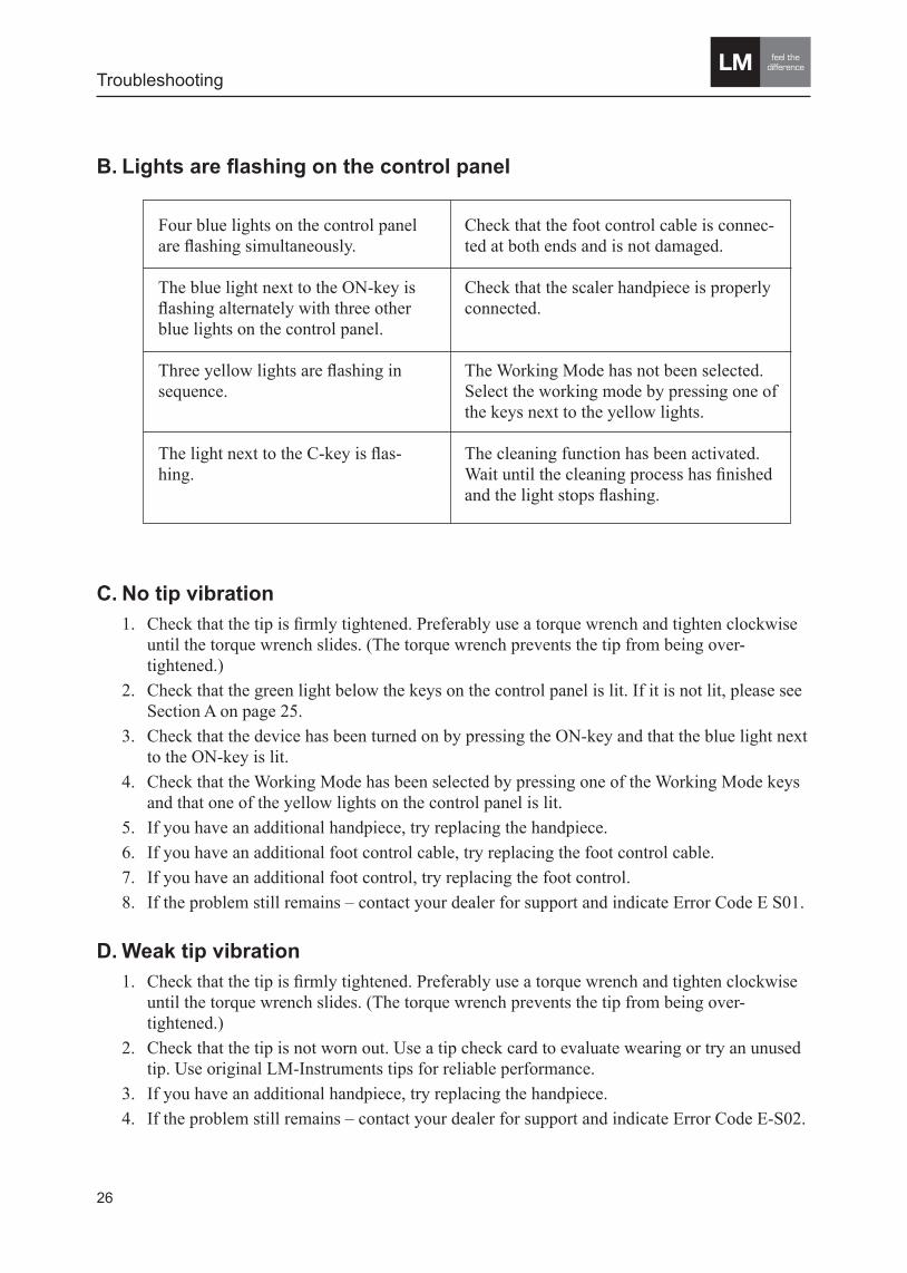
C. No tip vibration 1. Check that the tip is firmly tightened. Preferably use a torque wrench and tighten clockwise
until the torque wrench slides. (The torque wrench prevents the tip from being over- tightened.)
2. Check that the green light below the keys on the control panel is lit. If it is not lit, please see Section A on page 25.
3. Check that the device has been turned on by pressing the ON-key and that the blue light next to the ON-key is lit.
4. Check that the Working Mode has been selected by pressing one of the Working Mode keys and that one of the yellow lights on the control panel is lit.
5. If you have an additional handpiece, try replacing the handpiece. 6. If you have an additional foot control cable, try replacing the foot control cable. 7. If you have an additional foot control, try replacing the foot control.8. If the problem still remains – contact your dealer for support and indicate Error Code E S01.
D. Weak tip vibration1. Check that the tip is firmly tightened. Preferably use a torque wrench and tighten clockwise
until the torque wrench slides. (The torque wrench prevents the tip from being over- tightened.)
2. Check that the tip is not worn out. Use a tip check card to evaluate wearing or try an unused tip. Use original LM-Instruments tips for reliable performance.
3. If you have an additional handpiece, try replacing the handpiece.4. If the problem still remains – contact your dealer for support and indicate Error Code E-S02.
B. Lights are flashing on the control panel
Four blue lights on the control panel are flashing simultaneously.
The blue light next to the ON-key is flashing alternately with three other blue lights on the control panel.
Three yellow lights are flashing in sequence.
The light next to the C-key is flas-hing.
Check that the foot control cable is connec-ted at both ends and is not damaged.
Check that the scaler handpiece is properly connected.
The Working Mode has not been selected. Select the working mode by pressing one of the keys next to the yellow lights.
The cleaning function has been activated. Wait until the cleaning process has finished and the light stops flashing.

27
Troubleshooting
E. Insufficient or no water flow when foot switch is activated1. If the unit are equipped with a water bottle: Check that the medicament/water bottle is
properly connected i.e. the cap is tightened and pushed in all the way onto the connector. Check that the o-rings on cap and connector are in good condition. Replace o-rings if worn. O-rings can be lubricated with a glycerine based lubricant (or vaseline).
2. If the unit are connected with tap water: Check that the tap water hose is properly connected to the back of the device and that the tap water system is OK (tap/valve is open and possible filter is OK).
3. Check that dry mode is not activated i.e. that the blue light next to the crossed-out water drop is not lit. If it is lit, press the ON-key.
4. Adjust the water control ring on the handpiece to fully open (dots aligned).5. Try with another tip.6. Use the LM-ProPower Fixer to check that the water hose inside the handpiece has not stuck
in the autoclave. Insert the Fixer carefully into the handpiece from the hose connector side. (To avoid the hose getting stuck, the water adjustment on the handpiece should be set to fully open before sterilization in autoclave.)
7. If the problem still remains – contact your dealer for support and indicate Error Code E-S04.
F. Tip does not fit smoothly onto the handpiece1. Clean handpiece threads with compressed air and try with a new tip.2. If the problem still remains, the threads of the handpiece may be damaged and the handpiece
needs to be replaced. Contact your dealer and indicate Error Code E-S06.
G. Difficulty to remove the ErgoGrip from the handpiece1. Grab the ErgoGrip gently near the lens and at the same time twist and slide it off the
handpiece.2. If the problem still remains, replace the ErgoGrip.
H. Handpiece is overheated during use1. Check that the fluid flow is sufficient (at least 20 ml/min).2. If the problem still remains, replace the handpiece and contact your dealer.
I. Weak or no LED light.1. Check that lens in the ErgoGrip is clear and clean. Clean or replace if necessary. 2. If you have an additional handpiece, try replacing the handpiece.3. If the problem still remains – contact your dealer for support and indicate Error Code E-S03.
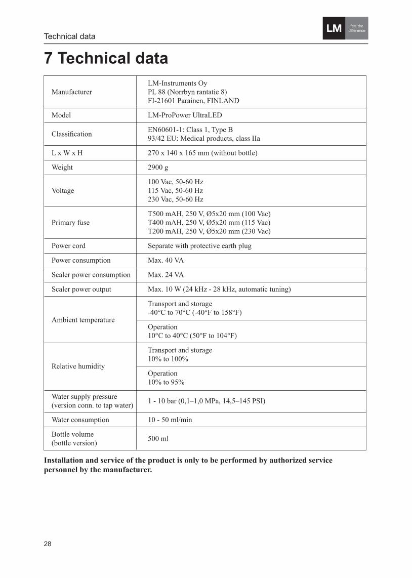
7 Technical data
Manufacturer LM-Instruments Oy
PL 88 (Norrbyn rantatie 8) FI-21601 Parainen, FINLAND
Model LM-ProPower UltraLED
Classification EN60601-1: Class 1, Type B 93/42 EU: Medical products, class IIa
L x W x H 270 x 140 x 165 mm (without bottle)
Weight 2900 g
Voltage 100 Vac, 50-60 Hz
115 Vac, 50-60 Hz 230 Vac, 50-60 Hz
Primary fuse T500 mAH, 250 V, Ø5x20 mm (100 Vac)
T400 mAH, 250 V, Ø5x20 mm (115 Vac) T200 mAH, 250 V, Ø5x20 mm (230 Vac)
Power cord Separate with protective earth plug
Power consumption Max. 40 VA
Scaler power consumption Max. 24 VA
Scaler power output Max. 10 W (24 kHz - 28 kHz, automatic tuning)
Ambient temperature
Transport and storage -40°C to 70°C (-40°F to 158°F)
Operation 10°C to 40°C (50°F to 104°F)
Relative humidity
Transport and storage 10% to 100%
Operation 10% to 95%
Water supply pressure (version conn. to tap water) 1 - 10 bar (0,1–1,0 MPa, 14,5–145 PSI)
Water consumption 10 - 50 ml/min
Bottle volume (bottle version) 500 ml
Installation and service of the product is only to be performed by aut horized service personnel by the manufacturer.
28
Technical data

Technical data
29
Medicaments that can be used• Clean water• Cetylpyridinium chloride• Clorhexidine• Essential oils• Hydrogen peroxide, 3% USP• Povidine iodine, 10% solution • Saline solution• Sangurinara extract• Sodium hypochlorite 1% solution
WARNING
Immedately after using any kind of medicament in the medicament bottle, run the automatic cleaning cycle with clean water in the med-icament bottle for both the scaler and the polisher un-til clean water comes out of the handpieces.
6
Safety notices in this manual
Warning indicates a potentially dangerous situation. Non-observ-ance may lead to death or injury.
Caution indicates a potentially harmful situation. Non-observ-ance may damage the equipment.
Note indicates a situation where special notice should be ob-served.
WARNING
Caution
Note

30
Warranty and declaration
8 Warranty and Declaration of conformity 8.1 Warranty TermsThe following warranty terms apply to the sale of LM-Instrument Oy’s products (hereinafter “Products”) to a purchasing company or individual by LM-Instruments Oy (hereinafter “Manufacturer”).
Manufacturer hereby warrants that the Products will be free from defects arising from faulty materi-als or workmanship for a period of twenty four (24) months from the date of purchase by a customer from Manufacturer’s authorized dealer (hereinafter “Authorized Dealer”). The warranty period is exceptionally three (3) months for products with a life inherently shorter than 24 months due to normal wear and tear, for example tips of ultrasonic scalers, tips of endodontic files.
This warranty shall not apply to Products or parts thereof; which have been subject to abuse, misuse, negligence or accident or are not connected to proper power supply; to which any modification, alteration or attachment has been made without written consent of the Manufacturer; or which are installed or operated violating instructions for installation, use and maintenance; which are normally consumed in operation.
The sole and exclusive remedy under this warranty shall be limited to correct or circumvent the errors or to repair or replacement of defective parts of Products by the Manufacturer, EXW Manufacturer’s factory, providing that a written claim of the defect is sent to the Manufacturer within the warranty period and the original part is returned to Manufacturer’s factory by the Authorized Dealer, and Manufacturer’s inspection establishes the existence of such a defect.
The customer must contact the Authorized Dealer from whom the products were purchased to request repair or replacement under this warranty and a written claim of the defects and send the original Product the Authorized Dealer.
This warranty is void if service or repair is performed by persons not authorized by the manufacturer.
Any Products not manufactured by the Manufacturer, carries only such warranty, if any, as given by any manufacturer thereof.
This warranty is the Manufacturer’s only warranty in respect of the Products and the Manufacturer disclaims all other warranties, whether of merchantability, fitness for particular purpose or otherwise, guarantees and liabilities, express or implied, arising by law or otherwise. In no event shall the Manufacturer be liable for any general, consequential or incidental damages, loss of use or loss of profits by reason of the manufacturer’s negligence or otherwise in connection with the sale, delivery, installation, repair or use of the Products.
The Manufacturer shall have no liability whatsoever to the Authorized Dealer or customer or any other person for or on account of any injury, loss or damage of any kind or nature, sustained by, or any damages assessed or asserted against, or any other liability incurred by or imposed upon the handling, use, operation, maintenance or repairs of Products by anyone other than the Manufacturer. This exclusion of liability does not apply pursuant to the laws on product liability in case of personal injury and property damage to privately used objects resulting from the Products.

Warranty and declaration
31
8.2 Declaration of conformityThe manufacturer hereby declares that theLM-ProPower UltraLED unitClass I, type B according to EN60601-1 equipped with original acces-sories conforms to the essential requirements of the Medical Device Directive 93/42/EEC with reference to the following harmonized standards:
IEC 60601-1, Third edition 2005 EN 60601-1: 2006
Classification: Medical products, Class IIa:
0537
WARNING
No modification of this equipment is allowed.
6
Safety notices in this manual
Warning indicates a potentially dangerous situation. Non-observ-ance may lead to death or injury.
Caution indicates a potentially harmful situation. Non-observ-ance may damage the equipment.
Note indicates a situation where special notice should be ob-served.
WARNING
Caution
Note
Warranty and declaration
32
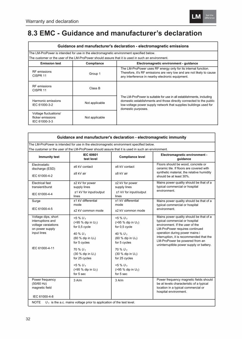
8.3 EMC - Guidance and manufacturer’s declaration
The LM-ProPower uses RF energy only for its internal function.Therefore, it's RF emissions are very low and are not likely to cause any interference in nearby electronic equipment.
Group 1RF emissionsCISPR 11
RF emissionsCISPR 11
Class B
The LM-ProPower is suitable for use in all establishments, including domestic establishments and those directly connected to the public low-voltage power supply network that supplies buildings used for domestic purposes.
Harmonic emissionsIEC 61000-3-2
Not applicable
Voltage fluctuations/flicker emissionsIEC 61000-3-3
Not applicable
Guidance and manufacturer's declaration - electromagnetic emissions
Emission test Compliance Electromagnetic environment - guidance
The LM-ProPower is intended for use in the electromagnetic environment specified below.
The customer or the user of the LM-ProPower should assure that it is used in such an environment.
The LM-ProPower is intended for use in the electromagnetic environment specified below.
The customer or the user of the LM-ProPower should assure that it is used in such an environment.
3 A/m 3 A/m
IEC 61000-4-8
<5 % U T
(>95 % dip in UT)for 0,5 cycle
40 % U T
(60 % dip in UT)for 5 cycles
70 % U T
(30 % dip in UT)for 25 cycles
<5 % U T
(>95 % dip in UT)for 5 sec
±2 kV for powersupply lines
±1 kV for input/output lines
±1 kV differentialmode
±2 kV common mode
NOTE U T is the a.c. mains voltage prior to application of the test level.
Power frequency magnetic fields should be at levels characteristic of a typical location in a typical commercial or hospital environment.
Mains power quality should be that of a typical commercial or hospital environment.
Mains power quality should be that of a typical commercial or hospital environment.
Power frequency(50/60 Hz)magnetic field
±2 kV for powersupply lines
±1 kV for input/output lines
±1 kV differentialmode
±2 kV common mode
Electrical fast transient/burst
Floors should be wood, concrete or ceramic tile. If floors are covered with synthetic material, the relative humidity should be at least 30%.
Electromagnetic environment -guidance
Electrostaticdischarge (ESD)
IEC 61000-4-2
±6 kV contact
±8 kV air
±6 kV contact
±8 kV air
IEC 61000-4-4
Surge
IEC 61000-4-5
<5 % U T
(>95 % dip in UT)for 0,5 cycle
40 % U T
(60 % dip in UT)for 5 cycles
70 % U T
(30 % dip in UT)for 25 cycles
<5 % U T
(>95 % dip in UT)for 5 sec
Guidance and manufacturer's declaration - electromagnetic immunity
Mains power quality should be that of a typical commercial or hospital environment. If the user of the LM-ProPower requires continued operation during power mains iinterruption, it is recommended that the LM-ProPower be powered from an uninterruptible power supply or battery.
Immunity testIEC 60601test level
Compliance level
Voltage dips, short interruptions andvoltage varaiationson power supplyinput lines
IEC 61000-4-11

Warranty and declaration
33
The LM-ProPower is intended for use in the electromagnetic environment specified below.
The customer or the user of the LM-ProPower should assure that it is used in such an environment.
b Over the frequency range 150 kHz to 80 MHz, field strengths should be less than 3 V/m.
Field strengths from fixed transmitters, such as base stations fro radio (cellular/cordless) telephones and land mobile radios,amateur radio, AM and FM radio broadcast and TV broadcast cannot be predicted theoretically with accuracy. To assess the electromagnetic environment due to fixed RF transmitters. an electromagnetic site survey should be considered. If the measured field strength in the location in which the LM-ProPower is used exceeds the applicable RF compliance level above, the LM-ProPower should be observed to verify normal operation. If abnormal performance is observed additional measures may be necessary, such as reorienting or relocating the LM-ProPower.
a
Guidance and manufacturer's declaration - electromagnetic immunity
Immunity test IEC 60601 test levelCompliance
levelElectromagnetic environment - guidance
Portable and mobile RF communications equipment should be used no closer to any part of the LM-ProPower including cables, than the recommended separation distance calculated from the equation applicable to the frequency of the transmitter.
d = 2,3√P 800 MHz to 2,5 GHZ
NOTE 1 At 80 MHz and 800 MHz, the higher frequency range applies.
Recommended separation distance
IEC 61000-4-3 80 MHz to 2,5 GHz
Conducted RF
IEC 61000-4-6
3 Vrms
150 kHz to 80 MHz
3 V d = 1,2√P
Radiated RF 3 V/m 3 V/m d = 1,2√P 80 MHz to 800 MHz
were P is the maximum output power rating of the transmitter in watts (W) according to the transmitter manufacturer and d is the recommended separation distance in metres (m).
Field strengths from fixed RF transmitters as deter-
mined by an electromagnetic site survey,a should be less
than the compliance level in each frequency range.b
Interference may occur in the vicinity of equipment marked with the following symbol:
NOTE 2 These guidelines may not apply in all situations. Electromagnetic propagation is affected by absorption and reflectionfrom structures, objects and people.

34
Warranty and declaration
150 kHz to 80 MHz
NOTE 1 At 80 MHz and 800 MHz, the separation distance for the higher frequency range applies.
NOTE 2 These guidelines may not apply in all situations. Electromagnetic propagation is affected by absorption and reflection from structures, objects and people.
12
0,23
0,73
2,3
7,3
23
0,12
0,38
1,2
3,8
100 12
0,1
1
10
0,12
0,38
1,2
3,8
W d = 1,2√P d = 1,2√P
0,01
d = 2,3√P
Recommended separation distances betweenportable and mobile RF communications equipment and the LM-ProPower
The LM-ProPower is intended for use in an electromagnetic environment in which radiated RF disturbances are controlled. The customer or the user of the equipment can help prevent electromagnetic interference by maintaining aminimum distance between portable and mobile RF communications equipment (transmitters) and the LM-ProPower as recommended below, according to the maximum output power of the communications equipment.
Separation distance according to frequency of transmitterm
For transmitters rated at a maximum output power not listed above, the recommended separation distance d in metres (m) can be estimated using the equation applicable to the frequency of the transmitter, where P is the maximum output power rating of the transmitter in watts (W) according to the transmitter manufacturer.
Rated maximum output power of transmitter
150 kHz to 80 MHz 80 MHz to 800 MHz 800 MHz to 2,5 GHz

35

www.lm-dental.com/Downloads
9770
035
G
03
14E
N
LMDentalLM-Instruments Oy
PL 88 (Norrbyn rantatie 8)
FI-21601 Parainen, Finland
Tel. +358 2 4546 400
Fax +358 2 4546 444
www.lm-dental.com