
LK3-B430E LK3-B431E LK3-B432E LK3-B433E · ii LK3-B430E-, B431E-, B432E-, B433E- Mark II Use the...
73
� INSTRUCTION MANUAL Please read this manual before using the machine. Please keep this manual within easy reach for quick reference. ELECTRONIC LOCKSTITCH BAR TACKER ELECTRONIC LOCKSTITCH BELT LOOP BAR TACKER ELECTRONIC LOCKSTITCH EYELET BUTTONHOLE END BAR TACKER ELECTRONIC LOCKSTITCH DECORATIVE PATTERN TACKER LK3-B430E LK3-B431E LK3-B432E LK3-B433E
Transcript of LK3-B430E LK3-B431E LK3-B432E LK3-B433E · ii LK3-B430E-, B431E-, B432E-, B433E- Mark II Use the...
�
INSTRUCTION MANUAL
Please read this manual before using the machine.Please keep this manual within easy reach for quick reference.
ELECTRONIC LOCKSTITCH BAR TACKERELECTRONIC LOCKSTITCH BELT LOOP BAR TACKERELECTRONIC LOCKSTITCH EYELET BUTTONHOLE ENDBAR TACKERELECTRONIC LOCKSTITCH DECORATIVE PATTERN TACKER
LK3-B430ELK3-B431ELK3-B432ELK3-B433E
iLK3-B430E-, B431E-, B432E-, B433E- Mark II
Thank you very much for buying a BROTHER sewing machine. Before using your new machine, please read the safety instruc-tions below and the explanations given in the instruction manual.
With industrial sewing machines, it is normal to carry out work while positioned directly in front of moving parts such as theneedle and thread take-up lever, and consequently there is always a danger of injury that can be caused by these parts. Followthe instructions from training personnel and instructors regarding safe and correct operation before operating the machine sothat you will know how to use it correctly.
SAFETY INSTRUCTIONS
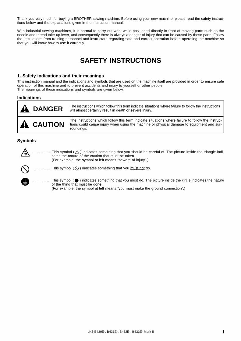
1. Safety indications and their meaningsThis instruction manual and the indications and symbols that are used on the machine itself are provided in order to ensure safeoperation of this machine and to prevent accidents and injury to yourself or other people.The meanings of these indications and symbols are given below.
Indications
The instructions which follow this term indicate situations where failure to follow the instruc-tions could cause injury when using the machine or physical damage to equipment and sur-roundings.
Symbols
................ This symbol ( ) indicates something that you should be careful of. The picture inside the triangle indi-cates the nature of the caution that must be taken.(For example, the symbol at left means “beware of injury”.)
................ This symbol ( ) indicates something that you must not do.
................ This symbol ( ) indicates something that you must do. The picture inside the circle indicates the natureof the thing that must be done.(For example, the symbol at left means “you must make the ground connection”.)
CAUTION
The instructions which follow this term indicate situations where failure to follow the instructionswill almost certainly result in death or severe injury.DANGER

ii LK3-B430E-, B431E-, B432E-, B433E- Mark II
Use the sewing machine in an area which is free fromsources of strong electrical noise such as high-frequency welders.Sources of strong electrical noise may cause prob-lems with correct operation.
Any fluctuations in the power supply voltage shouldbe within ±10% of the rated voltage for the machine.Voltage fluctuations which are greater than this maycause problems with correct operation.
The power supply capacity should be greater than therequirements for the sewing machine's electricalconsumption.Insufficient power supply capacity may cause prob-lems with correct operation.
CAUTION
The ambient temperature should be within the rangeof 5°C to 35°C during use.Temperatures which are lower or higher than this maycause problems with correct operation.
The relative humidity should be within the range of 45%to 85% during use, and no dew formation should occurin any devices.Excessively dry or humid environments and dew for-mation may cause problems with correct operation.
Avoid exposure to direct sunlight during use.Exposure to direct sunlight may cause problems withcorrect operation.
In the event of an electrical storm, turn off the powerand disconnect the power cord from the wall outlet.Lightning may cause problems with correct operation.
Environmental requirements
Machine installation should only be carried out by aqualified technician.
Contact your Brother dealer or a qualified electricianfor any electrical work that may need to be done.
The sewing machine weighs more than 47 kg. Theinstallation should be carried out by two or more people.
Do not connect the power cord until installation iscomplete, otherwise the machine may operate if thefoot switch is pressed by mistake, which could resultin injury.
Hold the machine head with both hands when tilting itback or returning it to its original position.
Furthmore, after tilring back the machine head, do notpush the face plate side or the pulley side from above,as this could cause the machine head to topple over,which may result in personal injury or damage to themachine.
Be sure to connect the ground. If the ground connec-tion is not secure, you run a high risk of receiving aserious electric shock, and problems with correctoperation may also occur.
All cords should be secured at least 25 mm away fromany moving parts. Furthermore, do not excessivelybend the cords or secure them too firmly with staples,otherwise there is the danger that fire or electric shockscould occur.
Install the belt covers to the machine head and motor.
If using a work table which has casters, the castersshould be secured in such a way so that they cannotmove.
Be sure to wear protective goggles and gloves whenhandling the lubricating oil and grease, so that they donot get into your eyes or onto your skin, otherwise in-flammation can result.Furthermore, do not drink the oil or eat the grease un-der any circumstances, as they can cause vomitingand diarrhoea.Keep the oil out of the reach of children.
Installation
2. Notes on safety
Wait at least 5 minutes after turning off the power switch and disconnecting the power cord from the wall outlet beforeopening the face plate of the control box. Touching areas where high voltages are present can result in severe injury.
DANGER

iiiLK3-B430E-, B431E-, B432E-, B433E- Mark II
CAUTION
Set the needle to the needle up stop position beforeturning off the power.If this is not done, the wiper may strike the needle,which might cause the needle to break.
Turn off the power switch before carrying out cleaning,otherwise the machine may operate if the foot switchis pressed by mistake, which could result in injury.
Be sure to wear protective goggles and gloves whenhandling the lubricating oil and grease, so that they donot get into your eyes or onto your skin, otherwise in-flammation can result.Furthermore, do not drink the oil or eat the grease un-der any circumstances, as they can cause vomitingand diarrhoea.Keep the oil out of the reach of children.
This sewing machine should only be used by opera-tors who have received the necessary training in safeuse beforehand.
The sewing machine should not be used for anyapplications other than sewing.
Be sure to wear protective goggles when using themachine.If goggles are not worn, there is the danger that if aneedle breaks, parts of the broken needle may enteryour eyes and injury may result.
Set the needle to the needle up stop position beforeturning off the power.If this is not done, the wiper may strike the needle,which might cause the needle to break.
Turn off the power switch at the following times,otherwise the machine may operate if the foot switchis pressed by mistake, which could result in injury.• When threading the needle• When replacing the needle and bobbin• When not using the machine and when leaving the
machine unattended
If using a work table which has casters, the castersshould be secured in such a way so that they cannotmove.
Attach all safety devices before using the sewingmachine. If the machine is used without these devicesattached, injury may result.
Do not touch any of the moving parts or press anyobjects against the machine while sewing, as this mayresult in personal injury or damage to the machine.
If an error occurs in machine, or if abnormal noises orsmells are noticed, immediately turn off the powerswitch. Then contact your nearest Brother dealer or aqualified technician.
If the machine develops a problem, contact yournearest Brother dealer or a qualified technician.
Sewing
Cleaning
Hold the machine head with both hands when tilting itback or returning it to its original position.Furthermore, after tilting back the machine head, donot push the face plate side or the pulley side fromabove, as this could cause the machine head to toppleover, which may result in personal injury or damage tothe machine.
Use only the proper replacement parts as specified byBrother.
If any safety devices have been removed, be abso-lutely sure to re-install them to their original positionsand check that they operate correctly before using themachine.
Any problems in machine operation which result fromunauthorized modifications to the machine will not becovered by the warranty.
Maintenance and inspection of the sewing machineshould only be carried out by a qualified technician.
Ask your Brother dealer or a qualified electrician tocarry out any maintenance and inspection of theelectrical system.
Set the needle to the needle up step position beforeturning off the power.If this is not done, the wiper may strike the needle,which might cause the needle to break.
Turn off the power switch and disconnect the powercord from the wall outlet at the following times,otherwise the machine may operate if the foot switchis pressed by mistake, which could result in injury.• When carrying out inspection, adjustment and
maintenance• When replacing consumable parts such as the ro-
tary hook
If the power switch needs to be left on when carryingout some adjustment, be extremely careful to observeall safety precautions.
Maintenance and inspection

iv LK3-B430E-, B431E-, B432E-, B433E- Mark II
Safety devicesEye guardFinger guardThread take-up coverThread take-up solenoid coverBelt coverMotor cover, etc.
2
Moving partsmay cause injury.
Operate with safety devices.Turn off main switch before threading, changing bobbin and needle, cleaning etc.
3 Be sure to connect the ground. If the ground connection is not secure, you run a high risk of receiving aserious electric shock, and problems with correct operation may also occur.
The following warning labels appear on the sewing machine.Please follow the instructions on the labels at all times when using the machine. If the labels have been removed or aredifficult to read, please contact your nearest Brother dealer.
3. Warning labels
1
Hazardous voltagewill cause injury.
Turn off main switch and wait 5 minutes before opening this cover.
Un voltage non adaptéprovoque des blessures.
Eteindrel'interrupteur et attendre 5 minutes avantd' ouvrir le capot
Hochspannungverletzungsgefahr!
Bitte schalten sie den hauptschalter aus und warten sie 5 minuten, bevor sie dieseabdeckung öffnen.
Un voltaje inadecuadopuede provocar las heridas.
Apagar el interruptorprincipal y esperar 5 minutos antes de abrir esta cubierta.
Eye guard
Thread take-up solenoidcover Finger
guard
2
Motor cover
3
4 Direction of operation
Threadtake-upcover
4
Belt cover
1
LK3-B430E Mark IILK3-B432E Mark IILK3-B433E Mark II
[LK3-B431E Mark II]
Thread take-up cover
Eye guard
Thread take-upsolenoid cover
Motor coverBelt cover
1
3
2
4
Fingerguard
B432E Mark II

LK3-B430E-, B431E-, B432E-, B433E- Mark II
CONTENTS
1. NAME OF EACH PART ............................... 01
2. SPECIFICATIONS ......................................... 02
2-1. Specifications ....................................... 2
2-2. Program list .......................................... 3
3. INSTALLATION............................................. 07
3-1. Power table ........................................... 73-2. Installing the motor ............................. 9
3-3. Installing the motor pulley .................. 93-4. Installing the control box .................... 103-5. Installing the rubber cushions ............ 11
3-6. Installing the oil pan ............................ 113-7. Installing the cushions ......................... 113-8. Installing the machine head ............... 12
3-9. Installing the head rest ........................ 123-10. Installing the liquid cooling tank,
optional ................................................. 12
3-11. Installing the operation panel ............. 133-12. Connecting the ground wire ............... 133-13. Connecting the cords ........................... 14
3-14. Installing the V-belt .............................. 153-15. Installing the belt cover ....................... 163-16. Installing the foot switch ..................... 16
3-17. Installing the motor cover ................... 173-18. Installing the spool stand .................... 173-19. Installing the eye guard ...................... 17
4. LUBRICATION ............................................... 18
4-1. Lubrication points ................................ 18
5. OPERATION .................................................. 19
5-1. Name and function of eachoperation panel item ........................... 19
5-2. Operating procedure ............................ 21
6. CHECKING THE SEWING PATTERN....... 22
7. CORRECT USE......................................... 23
7-1. Selecting the needle and thread ........ 237-2. Installing the needle ............................ 237-3. Threading the upper thread ................ 23
7-4. Winding the lower thread ................... 247-5. Replacing the bobbin case and
threading the thread ............................ 25
7-6. Sewing conditions and threadtension ................................................... 25
8. SEWING ................................................... 28
9. MAINTENANCE AND INSPECTION ....... 29
9-1. Cleaning the rotary hook .................... 299-2. Lubrication ............................................ 309-3. Draining the oil ..................................... 31
9-4. Cleaning the control box air inletport ........................................................ 31
9-5. Cleaning the eye guard ....................... 319-6. Checking the needle ............................ 31
10.STANDARD ADJUSTMENTS ................. 32
10-1. Adjusting the needle bar height ......... 3210-2. Adjusting the needle bar lift
amount .................................................. 32
10-3. Adjusting the driver needle guard ..... 3310-4. Adjusting the needle clearance .......... 3310-5. Adjusting the shuttle race thread
guide ...................................................... 3310-6. Adjusting the thread take-up
amount .................................................. 34
10-7. Adjusting the movable knife ............... 3410-8. Adjusting the work clamp lift
amount .................................................. 36
10-9. Work clamp pressure adjustment ...... 3710-10.Work clamp closing-distance
adjustment ............................................ 38
10-11.Work clamp interchangeability ........... 3810-12.Adjusting the needle up stop
position ................................................. 39
10-13.Adjusting the thread wiper ................. 3910-14.Checking the input sensor and
DIP switch input ................................... 40
10-15.Checking the input voltage ................. 4110-16.Clearing all memory settings ............. 4110-17.Moving stitch patterns ......................... 42
11.USING THE COUNTERS ......................... 43
11-1. Using the bobbin thread counter ....... 4311-2. Using the production counter ............ 43
12.CHANGING FUNCTIONS USINGTHE DIP SWITCHES ................................ 44
12-1. Operation panel DIP switches ............ 44
12-2. Setting the presser mode ................... 4412-3. DIP switches inside the control
box ......................................................... 45
12-4. Using user programs ........................... 46
13.CHANGING SPECIAL FUNCTIONSUSING THE MEMORY SWITCHES ........ 48
13-1. Using the cycle sewing function ........ 50
14.TABLE OF ERROR CODES ...................... 52
15.GAUGE PARTS LIST ACCORDINGTO SUBCLASSES .................................... 54
16.TROUBLESHOOTING ................................. 62
17.OPTIONAL PARTS ....................................... 65
1 LK3-B430E-, B431E-, B432E-, B433E- Mark II
1 . NAME OF EACH PART
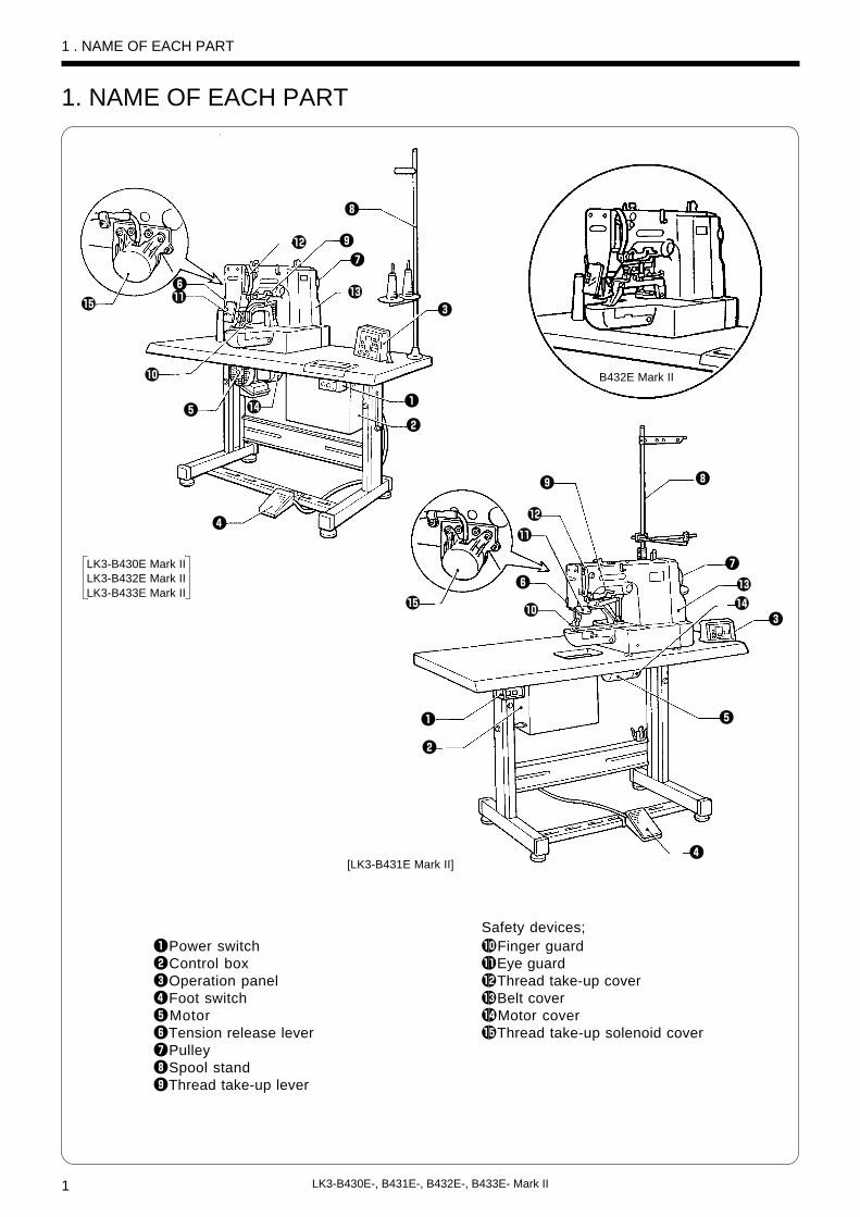
1. NAME OF EACH PART
Safety devices;qPower switch !0Finger guardwControl box !1Eye guardeOperation panel !2Thread take-up coverrFoot switch !3Belt covertMotor !4Motor coveryTension release lever !5Thread take-up solenoid coveruPulleyiSpool standoThread take-up lever
!5
y!1
!2 o
u
!3
i
e
q
w
r
!4t
!0
!5
o
!2
!1
y
!0
i
u
!3
!4
tq
w
e
r
LK3-B430E Mark IILK3-B432E Mark IILK3-B433E Mark II
[LK3-B431E Mark II]
B432E Mark II

2LK3-B430E-, B431E-, B432E-, B433E- Mark II
2 . SPECIFICATIONS2-1 . Specifications
2 . SPECIFICATIONS
Standard equipmentStandard equipment(Option for -2 spec.)
Maximum sewing speed
Maximum pattern size
Feed mechanism
Stitch length
Number of stitches
Maximum stitch number
Work clamp lifter
Work clamp height
Rotary hook
Wiper device
Thread trimmer device
Thread take-up device
Data storage method
Number of user programs
Number of stored data
Motor
Weights
Power source
Single needle lock stitch
2,500rpm2,700rpm
12 × 3 mm max. 30 × 30 mm max.30 × 10 mm max.
R-θ intermittent feed mechanism (pulse-motor driven mechanism)
0.1-10.0 mm
Variable ( 21, 28, 35, 42, 45 stitches pre-
set)
Variable ( 21, 28, 35 stitches pre-set) Variable
Variable (14, 15, 19, 21, 22, 28, 29, 30, 35,
42, 43, 45, 56, 64 stitches pre-set)
20,000 stitches (including 10,000 stitches which can be added)
Solenoid type
17 mm max.
Shuttle hook (shuttle hook 2, optional)
Standard equipment
Standard equipment
Standard equipment(Option for -2 spec.)
P-ROM (Any sewing pattern can be added using BAS-PC/300.)
16
(Up to 100 patterns can be added. Total number of stitches of stored data which can be added is within 10,000.)
6 sewing patterns are set already
3 sewing patterns are set already
33 sewing patterns are set already
Three-phase 400W induction motor
Machine head: 47kg, Operation panel: 0.6kg, Control box: 9-19kg (depending on destination)
Single-phase 220-230V 3-phase 220, 380, 400, 415V
Maximum electric power consumption; 600VA
Stitch formation
Number of cycle programs
4
LK3-B431E Mark II Electronic lockstitch belt loop bar tacker
LK3-B432E Mark II Electronic lockstitch eyelet buttonhole
end bar tacker
LK3-B433E Mark II Electronic lockstitch decorative pattern
tacker
LK3-B430E Mark II Electronic lockstitch
bar tacker
BROTHER INDUSTRIES, LTD.
MADE IN JAPAN
LK3-B430E-3BROTHER INDUSTRIES, LTD.
MADE IN JAPAN
LK3-B431E-3BROTHER INDUSTRIES, LTD.
MADE IN JAPAN
LK3-B432EBROTHER INDUSTRIES, LTD.
MADE IN JAPAN
LK3-B433E-3
527
DenimKnitted materials
Ordinary materials1
Bar tacking length 14 - 25mm3Bar tacking length 6 - 14mm2
Denim2Ordinary materials1
Knitted materials7

3 LK3-B430E-, B431E-, B432E-, B433E- Mark II
2-2 . Program listSewing patterns are limited as shown in the table below. (Any program is available as long as the sewingpattern is within the work clamp and feed plate in size.)The sewing size is the length when the enlargement/reduction ratio is 100%.[B430E Mark II]
-1
-5
-2
Use
For ordinary materials
For denim
Program No.
1
4
5
8
13
15
20
21
2
3
6
14
16
17
18
19
Sewing patternNo. of
stitches
42
30
29
21
35
42
28
35
42
35
30
35
43
42
56
64
Standard bar tacking length
16mm
16mm
10mm
7mm
10mm
10mm
7mm
7mm
20mm
20mm
16mm
16mm
16mm
24mm
24mm
24mm
Standard bar tacking width
2mm
2mm
2mm
2mm
2mm
2mm
2mm
2mm
3mm
3mm
3mm
3mm
3mm
3mm
3mm
3mm
Specifica-tion
2 . SPECIFICATIONS
* The difference between -1 and -5 specifications for ordinary material is that the standard presser foot andfeed plate are different.

4LK3-B430E-, B431E-, B432E-, B433E- Mark II
31
32
33
28
22
15
8mm
8mm
8mm
2mm
2mm
2mm
-7
Use
For knitted materials
Program No.
7
9
22
Sewing patternNo. of
stitches
28
21
14
Standard bar tacking length
8mm
7mm
7mm
Standard bar tacking width
2mm
2mm
2mm
Specifica-tion
Program No.
10
11
12
23
24
25
Sewing patternNo. of
stitches
21
28
28
35
42
45
Standard bar tacking length
10mm
10mm
20mm
25mm
25mm
25mm
Standard bar tacking width
0.3mm
0.3mm
0.3mm
0.3mm
0.3mm
0.3mm
* To prevent thread breakage due to heat, set the sewing speed to a maximum of 2,500 rpm for sewingknitted materials.
* The sewing start and sewing end of the sewing patterns for program numbers 31 to 33 are in the middle ofthe pattern.
<Straight bar tacking>
2 . SPECIFICATIONS
* Use the presser foot and feed plate for straight bar tacking when using theabove programs.

5 LK3-B430E-, B431E-, B432E-, B433E- Mark II
Vertical bar tacking
vertical straight bar
tacking
Sewing patternProgram No.
26
27
28
29
30
No. of stitches
28
35
19
21
28
Standard bar tacking length
3mm
3mm
0.3mm
0.3mm
0.3mm
Standard bar tacking width
10mm
10mm
10mm
10mm
10mm
<Vertical bar tacking &vertical straight bartacking>
2 . SPECIFICATIONS
* Use the presser foot and feed plate for straight bar tacking when using the aboveprograms.
If you want to sew a pattern other than standerd patterns, you can create your original pattern using the BAS-PC/300. Consult with your local Brother sales Office for details.
6LK3-B430E-, B431E-, B432E-, B433E- Mark II
Program No.
1
2
3
4
5
6
Sewing patternNo. of
stitches
21
28
28
35
42
45
Standard bar tacking length
10mm
10mm
20mm
25mm
25mm
25mm
Standard bar tacking width
0.3mm
0.3mm
0.3mm
0.3mm
0.3mm
0.3mm
2 . SPECIFICATIONS
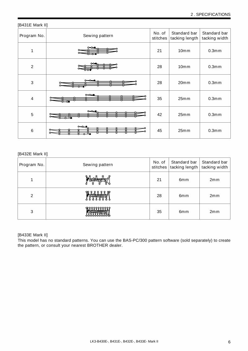
[B431E Mark II]
Program No.
1
2
3
Sewing patternNo. of
stitches
21
28
35
Standard bar tacking length
6mm
6mm
6mm
Standard bar tacking width
2mm
2mm
2mm
[B432E Mark II]
[B433E Mark II]This model has no standard patterns. You can use the BAS-PC/300 pattern software (sold separately) to createthe pattern, or consult your nearest BROTHER dealer.

7 LK3-B430E-, B431E-, B432E-, B433E- Mark II
Machine installation should only be carriedout by a qualified technician.
Contact your Brother dealer or a qualifiedelectrician for any electrical work that mayneed to be done.
The sewing machine head weighs more than47 kg. The installation should be carried outby two or more people.
Do not connect the power cord until installa-tion is complete, otherwise the machine mayoperate if the foot switch is depressed by mis-take, which could result in injury.
Hold the machine head with both hands whentilting it back or returning it to its original posi-tion. Furthermore, after tilting back the ma-chine head, do not push the face plate sideor the pulley side from above, as this couldcause the machine head to topple over, whichmay result in personal injury or damage tothe machine.
All cords should be secured at least 25 mmaway from any moving parts. Furthermore,do not excessively bend the cable or se-cure it too firmly staples, otherwise there isthe danger that fire or electric shocks couldoccur.
Be sure to connect the ground. If the groundconnection is not secure, you run the riskof receiving a serious electric shock, andproblems with correct operation may alsooccur.
Install the belt covers to the machine headand motor.
CAUTION
3. INSTALLATION
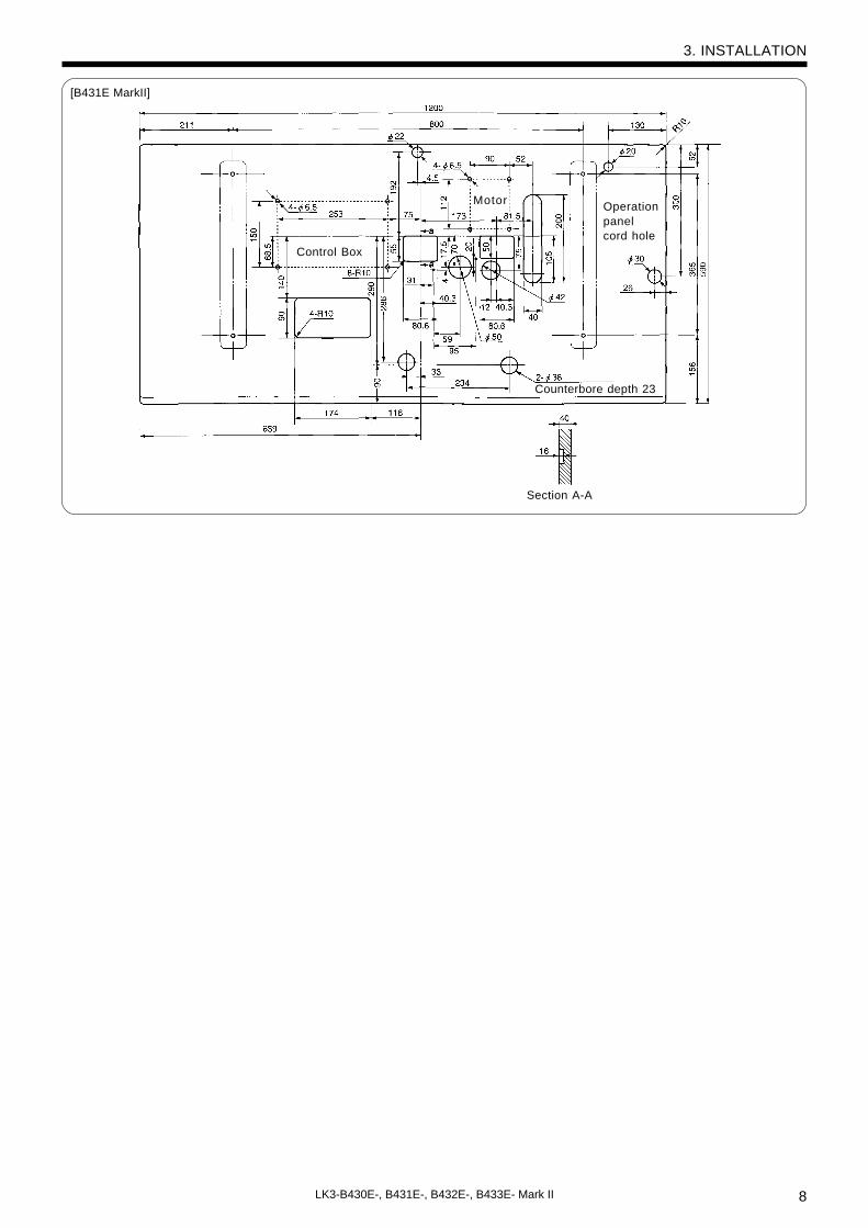
3-1 . Power table• Use the power table which has been specially
designed for each sewing machines.* If using a commercially-available table, process
it as shown in the illustration below.
NOTE:The thickness of the table should be at least 40 mm, and it should be strong enough to bear the weight and vibration ofthe sewing machine.If the distance A between the insides of the legs is less than 740 mm, move the control box installation position closerto the motor (B = 247 mm).Check that the control box is at least 10 mm away from the leg. If the control box and leg are touching, it could cause thesewing machine to operate incorrectly.
B431E Mark II
Model code
127-V30-00001
127-V31-00001
Table/ legs assembly
ModelB430E-, B432E-, B433E
Mark II
3. INSTALLATION
Motor
Control Box
2-ø3
depth 5
Counterboredepth 23
Section A-A
Operationpanel cordhole
LK3-B430E Mark IILK3-B432E Mark IILK3-B433E Mark II
b
8LK3-B430E-, B431E-, B432E-, B433E- Mark II
Motor
Control Box
Counterbore depth 23
Section A-A
[B431E MarkII]
3. INSTALLATION
Operationpanelcord hole

9 LK3-B430E-, B431E-, B432E-, B433E- Mark II
q
we
r
y
u
q
e
Table
1mm
t
q
w
e
3-2 . Installing the motorInstall the motor u to the work table with the four ac-cessory bolts q, cushions w, cushion collars e, flatwashers r, spring washers t and nuts y.At that time, fix by setting bolts q a little to the rightof oval hole on motor.
NOTE:Tighten the nuts y so that the clearance between the tableand the cushion collars e is approximately 1 mm.
3-3 . Installing the motor pulleyPlace the motor pulley q onto the shaft of the motorw so that the key groove is aligned, and then tightenthe set screw e so that the center of the V groove inthe motor pulley q is aligned as closely as possiblewith the center of the belt hole in the power table.
3. INSTALLATION

10LK3-B430E-, B431E-, B432E-, B433E- Mark II
!0
!1
!2
w
e q
oiu
yt
r
t
u
i
o
y
Table
Cushion collars
Nuts
Flat washers
Rubber collers3mm
!3
3-4 . Installing the control box
1. Remove the 12 screws q, and then open the covers (panel mounting assembly w and main P.C. boardmounting plate e).NOTE:
When opening the cover, hold it securely so that it does not fall down.2. Install the control box with the four accessory bolts r, cushions t, cushion collars y, rubber collars u,
flat washers i and nuts o as shown in the illustration above. At this time, leave a gap of approximately3 mm between the work table and the top of the box.* Use two nuts o at each installation location, and make sure that both nuts are tightened.
3. Close the covers (panel mounting assembly w and main P.C. board mounting plate e), and tighten themwith the screws q.* The main P.C. board mounting plate e will be opened again during “3-13. Connecting the cords”, so
provisionally tighten it with the screw q.4. Install the power switch !0 with the two screws !1.5. Secure the power switch cord with the three staples !2.6. Pass the motor cord through the cord hole !3.
3. INSTALLATION
LK3-B430E Mark IILK3-B432E Mark IILK3-B433E Mark II
Cushions
r
!0
ty
uio
qe
w
!1
!2
[LK3-B431E Mark II]
11 LK3-B430E-, B431E-, B432E-, B433E- Mark II
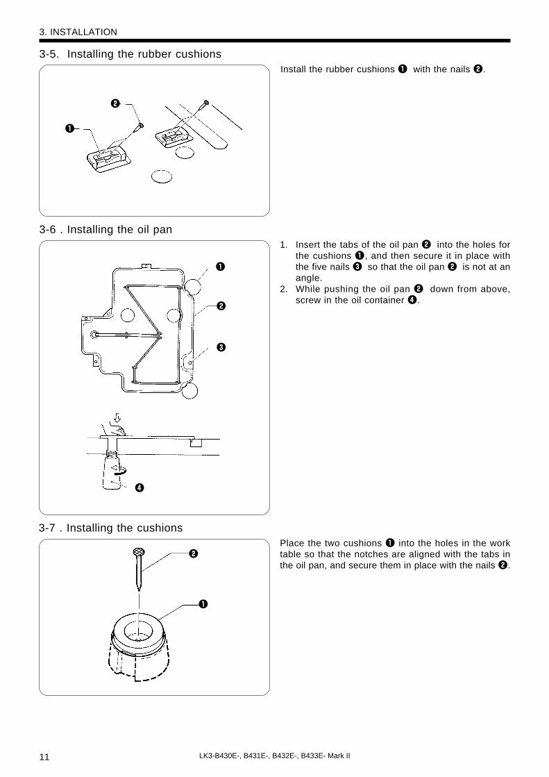
3-5. Installing the rubber cushions
3-6 . Installing the oil pan
3-7 . Installing the cushions
Install the rubber cushions q with the nails w.
1. Insert the tabs of the oil pan w into the holes forthe cushions q, and then secure it in place withthe five nails e so that the oil pan w is not at anangle.
2. While pushing the oil pan w down from above,screw in the oil container r.
Place the two cushions q into the holes in the worktable so that the notches are aligned with the tabs inthe oil pan, and secure them in place with the nails w.
3. INSTALLATION
w
w
e
q
r
w
q
q

12LK3-B430E-, B431E-, B432E-, B433E- Mark II
y
u
q
wq
3-8 . Installing the machine head
1. Insert the head hinges q into the machine head so that they are parallel, and then secure them with thetwo set screws w.
2. Place the machine head gently on top of the rubber cushions e and cushions r.NOTE:
Pull the cords t out as shown in the illustration above in order to prevent them from being clamped by the machinehead.
3. Install the hinge presser y with the two screws u.
3-9 . Installing the head restTap the head rest q into the table hole.NOTE:
Tap the head rest securely into the table hole.
3-10 .Installing the liquid cooling tank, optional1. Remove the rubber plug, and then push the liquid
cooling tank q.2. Tighten it with the set screw w.
3. INSTALLATION
w
e
q
r
t
66
13
17

13 LK3-B430E-, B431E-, B432E-, B433E- Mark II
Be sure to connect the ground. If the ground connection is not secure, you run the risk of receiv-ing a serious electric shock, and problems with correct operation may also occur.
t
e
w
r
w
rq
e
t
q
CAUTION
Table
Table
RedWhite
BlackYellow/Green
3-11 . Installing the operation panel
1. Install the rear frame q to the work table (top or bottom) with the four wood screws w.2. Install the front frame e to the rear frame q with the four screws r.
* The vertical orientation of the front frame e is the same whether it is installed to the top or the bottom ofthe work table.
3. Insert the connector cord t into the control box through the hole at the side of the box. Refer to “3-13.Connecting the cords” for details on connecting the cord.
4. Secure the connector cord t with the staples (in three places).
3-12 . Connecting the ground wire
Connect to the power switch. However, theblack wire is insulated to the inside of the boxand is not used.
3. INSTALLATION
The operation panel can be installed to either the top or bottom of the work table.
Top of work table Bottom of work table
Connect to ground

14LK3-B430E-, B431E-, B432E-, B433E- Mark II
Connection location
X, Y, Sewing sensor
Synchronizer
Machine specification select connectorThread take-up solenoid*Presser solenoidThread trimmer solenoid
Pulse motor, Y
Pulse motor, X
Operation panel
Upper shaft motor
No. of pins
12-pin
5-pin
8-pin
5-pin
4-pin
4-pin (blue)
4-pin
26-pin
3-pin
Cord mark
z
x
c
v
b
n
m
None
None
Connection location on circuit board
P1 (ORG2)
P2 (SYNCHRO)
P3 (SELECT)
P4 (SOL2)
P5 (SOL)
P6 (YPM)
P7 (XPM)
P8 (PANEL)
P11 (UVW)
Machine head connectors
w
q
!1
!0r
P11 P7P6
P5P4
e
P3P2
P1
P8
!3!2
q
o
ui
y
t
* Provided as an option for B430E Mark II-2 and B433E Mark II-2 specifications. In addition, theB432E Mark II also has a movable solenoid connected.
3-13 . Connecting the cords
1. Gently tilt back the machine head.NOTE:
After tilting back the machine head, do not push the face side or the pulley side from above.2. Pass the cords q through the hole w in the work table.3. Gently return the machine head to its original position.4. Remove the six screws e, and then open the control box cover (main P.C. board mounting plate r).
NOTE:When opening the cover, hold it securely so that it does not fall down.
5. Loosen the two screws t,and then open the cord presser plate y in the direction of the white arrow andpass the cords q through the opening.
6. Loosen the screw o, and then attach the ground cord u for the machine head and the ground cord i forthe operation panel as shown in the illustration.
7. Loosen the screw !1, and then attach the ground cord !0 for the upper shaft motor as shown in the illustra-tion.
8. Securely connect connectors P1 to P8 and P11 as indicated in the table.9. Secure the cords q with the cord clamps !2 and !3.10. Close the cord presser plate y in the direction of the black arrow, and secure it by tightening the screws t.
NOTE:Check that the cords do not get pulled when the machine head is tilted back gently.
11. Tighten the cover (main P.C. board mounting plate r) with the six screws e.
3. INSTALLATION

15 LK3-B430E-, B431E-, B432E-, B433E- Mark II
r Approx. 9-10mm10N
V-belt
Motor
A
B
3-14 . Installing the V-belt
Approx. 1mm
Sewingmachine
1. Gently tilt back the machine head, and then placethe V-belt q into the V grooves on the machinehead pulley w and the motor pulley e.NOTE:
After tilting back the machine head, do not push theface plate side or the pulley side from above.
2. Gently return the machine head to its original po-sition.* Be careful not to clamp the cords at this time.
3. Provisionally install the accessory tension pulleyassembly r with the accessory flat washer, springwasher and bolt.
4. Adjust the belt tension by moving the tension pul-ley assembly to the right and left so that there is 9--10 mm of deflection in the V-belt q when it isgently pushed in the middle with a force of ap-proximately 10 N. After adjusting, tighten the boltA to secure the left pulley assembly.
5. Move the right tension pulley so that there is agap of about 1 mm between it and the V-belt q,and then tighten the bolt B to secure the rightpulley assembly.NOTE:
Use brother specified V-belt (belt, VM).The V-belt q may stretch slightly when it is first used,so adjust the belt tension after about 3,000 cycles ofuse.When above belt tension is week, this will be cause offollowing problems;
• Noise & vibration become large.• Needle up stop position becomes unstable.• Error message [E-50] is displayed.Check that the motor is positioned so that the V-belt is straight. (Fig.1)
3. INSTALLATION
w
q
e
Fig.1

16LK3-B430E-, B431E-, B432E-, B433E- Mark II
e
q
w
[A]
[B]
w
q
e
rt
y
u
3-15 . Installing the belt cover
1. Loosen the two screws w of the upper cover q and the two screws r of bed cover Le.2. Insert the belt cover t in the direction of the arrow, and then secure it with the two screws w, the two
screws r and the screw y.* When tilting back the machine head, loosen the screws w and r, remove the screw y and then remove
the belt cover t first.3. Attach the rubber plug u to the belt cover.
3-16. Installing the foot switch
1. Insert the connector of the foot switch e into the connector w of the control box q.2. Install the foot switch e to the work table leg !2 with foot switch support plate A r, foot switch support
plate C t, the bolt y, spring washer u, flat washer i, bolt o, spring washer !0 and flat washer !1 asshown in Figure A.
♦ If foot switch support plate B !3 is used in a back-to-front position, it can be used as shown in Figure. B.1. Remove the screw !4 and rubber plug !5.
* Note that the spring !6 will come out when the screw !4 is removed.2. Turn foot switch support plate B !3 back to front, and then install it with the bolt !7, spring washer !8 and
flat washer !9 as shown in Figure. B.NOTE:
If using the foot switch without installing it to the work table leg, move the foot switch at least 10 mm away from theleg. If the foot switch is not fully in contact with the work table leg when the foot switch is used, for example, if it isjust hooked loosely onto the work table leg, it may cause the sewing machine to operate incorrectly.If using the optional two-pedal foot switch, change the setting of DIP switch A on the oreration panel while referringto "Setting the presser mode" on page 44.
3. INSTALLATION
!6
!0 e
r
t
y
!4
!9
!5
!8
!3
!7
!1
o
ui
!2
17 LK3-B430E-, B431E-, B432E-, B433E- Mark II
q
ew
q
CAUTION
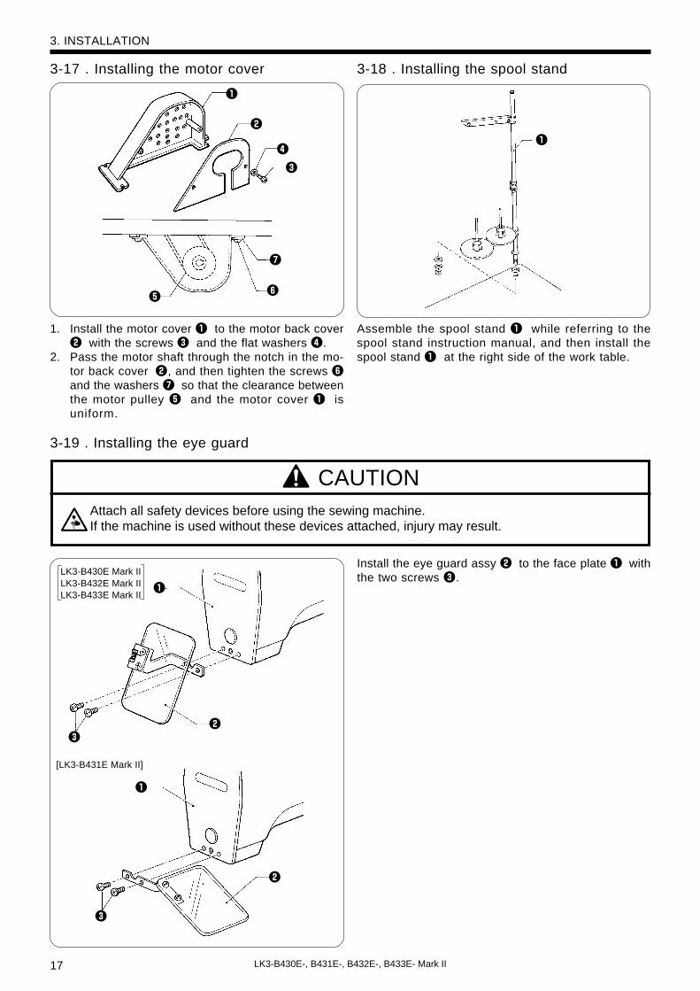
3-17 . Installing the motor cover
1. Install the motor cover q to the motor back coverw with the screws e and the flat washers r.
2. Pass the motor shaft through the notch in the mo-tor back cover w, and then tighten the screws yand the washers u so that the clearance betweenthe motor pulley t and the motor cover q isuniform.
3-18 . Installing the spool stand
Assemble the spool stand q while referring to thespool stand instruction manual, and then install thespool stand q at the right side of the work table.
3-19 . Installing the eye guard
Attach all safety devices before using the sewing machine.If the machine is used without these devices attached, injury may result.
Install the eye guard assy w to the face plate q withthe two screws e.
3. INSTALLATION
w
q
e
r
ty
u
LK3-B430E Mark IILK3-B432E Mark IILK3-B433E Mark II
[LK3-B431E Mark II]
q
w
e
18LK3-B430E-, B431E-, B432E-, B433E- Mark II
Turn off the power switch before starting lubricating, otherwise the machine may operate if thefoot switch is depressed by mistake, which could result in injury.
Be sure to wear protective goggles and gloves when handling the lubricating oil and grease, sothat they do not get into your eyes or onto your skin, otherwise inflammation can result.Furthermore, do not drink the oil or eat the grease under any circumstances, as they can causevomiting and diarrhoea.Keep the oil out of the reach of children.
CAUTION
4. LUBRICATION
4 . LUBRICATION
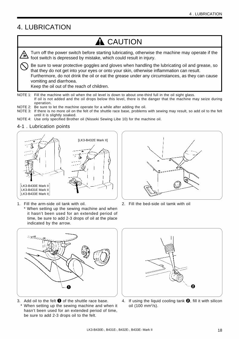
NOTE 1: Fill the machine with oil when the oil level is down to about one-third full in the oil sight glass.If oil is not added and the oil drops below this level, there is the danger that the machine may seize duringoperation.
NOTE 2: Be sure to let the machine operate for a while after adding the oil.NOTE 3: If there is no more oil on the felt of the shuttle race base, problems with sewing may result, so add oil to the felt
until it is slightly soaked.NOTE 4: Use only specified Brother oil (Nisseki Sewing Libe 10) for the machine oil.
4-1 . Lubrication points
1. Fill the arm-side oil tank with oil.* When setting up the sewing machine and when
it hasn’t been used for an extended period oftime, be sure to add 2-3 drops of oil at the placeindicated by the arrow.
2. Fill the bed-side oil tamk with oil
4. If using the liquid cooling tank w, fill it with siliconoil (100 mm2/s).
3. Add oil to the felt q of the shuttle race base.* When setting up the sewing machine and when it
hasn’t been used for an extended period of time,be sure to add 2-3 drops oil to the felt.
q w
LK3-B430E Mark IILK3-B431E Mark IILK3-B433E Mark II
[LK3-B432E Mark II]

19 LK3-B430E-, B431E-, B432E-, B433E- Mark II
5 . OPERATION5-1 . Name and function of each operation panel item
S E L E C T
PROGRAM NO.
R E S E T
COUNTER
X-SCALE
Y-SCALE
SPEED
P
T E S T
BOBBIN.WIND
P4P3
P1 P2POWER
B430E Series
q
w
r
e
t
y
u
i
o
!0
!1 !4
q POWER indicator .................. Illuminates when the power switch has been turned on.
w RESET switch ...................... . Press this switch to reset the machine when an error occurs.
e TEST switch ......................... Use this switch when you want to operate only the feed mechanism in orderto check a pattern.
r TEST indicator ...................... Illuminates when the TEST switch has been pressed.
t BOBBIN. WIND switch ......... Press this switch to wind the lower thread.
y SELECT switch ..................... Use this switch to select a menu (program number, X and Y feed, speed andcounter). Each time the switch is pressed, one of the menu indicators (u to!1) illuminates, and the setting for that menu item appears in the display !4.The illiminated indicator changes as follows each time the switch is pressed.
PROGRAM NO. indicator u →X-SCALE indicator i →Y-SCALE indicator o →SPEED indicator !0 →COUNTER indicator !1
u PROGRAM NO. indicator ..... Illuminates when the SELECT switch y is pressed to shown the programnumber setting.
5 . OPERATION

20LK3-B430E-, B431E-, B432E-, B433E- Mark II
S E L E C T
PROGRAM NO.
R E S E T
COUNTER
X-SCALE
Y-SCALE
SPEED
P
T E S T
BOBBIN.WIND
P4P3
P1 P2POWER
B430E Series
y
i
o
!0
!1 !4
!2
!3
i X-SCALE indicator ................ Illuminates when the SELECT switch y is pressed to shown the X-scale set-ting.
o Y-SCALE indicator ................ Illuminates when the SELECT switch y is pressed to shown the Y-scale set-ting.
!0 SPEED indicator ................... Illuminates when the SELECT switch y is pressed to shown the speed set-ting.
!1 COUNTER indicator ............. Illuminates when the SELECT switch y is pressed to show the bobbin threador production counter setting.
!2 DISPLAY SET switches ........ Used to change the menu details which are displayed in the window !4.
!3 User program switches ....... Used to set and select user programs.
!4 Display window .................... This display window will indicate the current statu for the selected menu,error or memory switch.
5 . OPERATION

21 LK3-B430E-, B431E-, B432E-, B433E- Mark II
5-2 . Operating procedure
Program No.
X-scale (%)
Y-scale (%)
Speed (rpm)
Factory default
0 *1
100
100
2,000
B431E MarkII B432E MarkII B433E MarkII
1 – 6 1 – 3 100 – *2
B430E MarkII
Variable range
1 – 33
20 – 200
20 – 200
1,000 –2,500 1,000 – 2,700
S E L E C T
PROGRAM NO.
COUNTER
X-SCALE
Y-SCALE
SPEED
P
S E L E C T
PROGRAM NO.
COUNTER
X-SCALE
Y-SCALE
SPEED
P
S E L E C T
PROGRAM NO.
COUNTER
X-SCALE
Y-SCALE
SPEED
P
Press the SELECT switch yuntil the PROGRAM NO. in-dicator illuminates.
Press the DISPLAY SETswitches !2 until the desiredprogram number is flashingin the display window.
Depress the foot switch tothe second step.* The display will stop flashing
and illuminates steadily, andthe feed mechanism will moveto the sewing start position.
This completes the setting of theprogram number.
1 2 3
Press the SELECT switch yuntil the X-scale or Y-scaleindicator illuminates.
Press the DISPLAY SETswitches !2 until the de-sired scale setting is flash-ing in the display window.(The setting is displayed as a per-
centage.)
Depress the foot switch tothe second step.* The display will stop flashing
and illuminates steadily, andthe feed mechanism will moveto the sewing start position.
1 2 3
Press the SELECT switch yuntil the SPEED indicator il-luminates.
Press the DISPLAY SETswitches !2 until the de-sired speed setting is flash-ing in the display window.
1 2
This completes the setting of the X-scale or Y-scale.
y
y
y
!2
!2
1st step2nd step
Preparation Turn on the power switch. (The POWER indicator q will illuminate and the pro- gram number will flash in the display window !4.)
*1 For checking the origin points for X and Y feed*2 Custom-made program
5-2-1 . Setting the program number
Determine the appropriate program from the program list which is given on pp. 3 - 5.
5-2-2 . Setting the X-scale and Y-scale
5-2-3 . Setting the sewing speed
1st step2nd step
NOTE:Be sure to check the sewing pattern(refer to page 22) after setting hasbeen completed to make sure thatthe needle hole does not go out ofthe area circumscribed by the workclamp.
5 . OPERATION
!2

22LK3-B430E-, B431E-, B432E-, B433E- Mark II
1. Turn on the power switch.(The POWER indicator will illuminate and the program number will flash in the display window.)
2. Press the TEST switch.(The TEST indicator will illuminate.)
3. Depress the foot switch to the second step.Only the feed mechanism will move.[Check that the needle hole q does not protrude past the frame of the work clamp w.]
* If you depress the foot switch again and keep it depresses after the feed mechanism has started to
move, the feeding speed will increase.
* If you would like to stop the feed while it is moving, press the TEST switch.
4. Press the TEST switch.(The TEST indicator will switch off and the test mode will be cleared.)
5. Depress the foot switch.The work clamp will rise and the preparation for sewing will be completed.
T E S T
T E S T
q
w
1st step2nd step
6. CHECKING THE SEWING PATTERN■ When checking by operating only the feed mechanism
To ensure safety during use ......You can prevent accidental changes being made toprograms by setting DIP switches 7 and 8 to ON.When DIP switch 7 is ON
... The sewing pattern cannot be enlarged.When DIP switch 8 is ON
... The program number cannot be changed.
6. CHECKING THE SEWING PATTERN
23 LK3-B430E-, B431E-, B432E-, B433E- Mark II
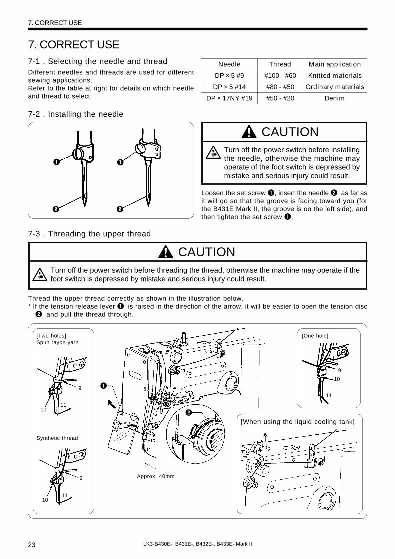
7. CORRECT USE7-1 . Selecting the needle and thread
DP × 5 #9
DP × 5 #14
DP × 17NY #19
Thread
#100 - #60
#80 - #50
#50 - #20
Main application
Knitted materials
Ordinary materials
Denim
Needle
q
w
9
1011
q
w
Approx. 40mm
[When using the liquid cooling tank]
Turn off the power switch before threading the thread, otherwise the machine may operate if thefoot switch is depressed by mistake and serious injury could result.
Turn off the power switch before installingthe needle, otherwise the machine mayoperate of the foot switch is depressed bymistake and serious injury could result.
Different needles and threads are used for differentsewing applications.Refer to the table at right for details on which needleand thread to select.
7-2 . Installing the needle
CAUTION
Loosen the set screw q, insert the needle w as far asit will go so that the groove is facing toward you (forthe B431E Mark II, the groove is on the left side), andthen tighten the set screw q.
7-3 . Threading the upper thread
Thread the upper thread correctly as shown in the illustration below.* If the tension release lever q is raised in the direction of the arrow, it will be easier to open the tension disc
w and pull the thread through.
7. CORRECT USE
Synthetic thread
q
w
9
1011
[Two holes]Spun rayon yarn
9
10
11
[One hole]
CAUTION

24LK3-B430E-, B431E-, B432E-, B433E- Mark II
8. To wind more thread ontothe bobbin, loosen the setscrew t and pull the bob-bin presser q outward.
1. Place the bobbin all the way onto the shaft.
2. Thread the thread as shown in the illustration atright, wind the thread around the bobbin sev-eral times in the direction of the arrow, and thenpress the bobbin presser q.
3. Turn on the power switch.(The POWER indicator on the operation panel willilluminate.)
4. Check that the needle is not touching the presser foot,and then while pressing the BOBBIN. WIND switch w, de-press the foot switch e to start the machine. Keep de-pressing the foot switch e until the lower thread stopsbeing wound onto the bobbin.
Release the BOBBIN. WIND switch w after the machine startsoperating. If you release the foot switch before winding is com-pleted, depress it once more while pressing and holding theBOBBIN. WIND switch w.
7. Remove the bobbin,hook the thread ontothe knife r, and thenpull the bobbin in thedirection of the arrowto cut the thread.
6. Release the foot switch e.
5. The bobbin presser q will automatically return to its original position after a set amount of thread (80 -90% of the bobbin capacity ) has been wound on.
q
BOBBIN.WIND
ew
Case A
Case B
CAUTION
7-4 . Winding the lower thread
Do not touch or place anything against any of the moving parts while winding the lower thread,otherwise personal injury or damage to the machine may result.
w
q
q
t
r
7. CORRECT USE
<<If the thread winds onto the bobbin unevenly>>If the thread winds onto the bobbin unevenly, loosenthe nut q and turn the bobbin winder thead tensionstud w to adjust.* If the thread winds on as shown in A, turn the bob-
bin winder thread tension stud w clokwise; if itwinds on as shown in B,turn the bobbin winderthead tension stud w counterclockwise.

25 LK3-B430E-, B431E-, B432E-, B433E- Mark II
Turn off the power switch before removing and replacing the bobbin case, otherwise the machinemay operate if the foot switch is depressed by mistake and serious injury could result.
q
30mm
Upper thread
Lower thread
Upper thread tension (N)
Lower thread tension (N)
Thread take-up spring height (mm)
Thread take-up spring tension (N)
Pre-tension (N)
Needle
Large hook
←�
←�
1.0 - 1.3
←�
←�
←�
←�
←� ←�
←�
←�
←�
←�
1.4 - 1.8
←�
←�
Large hook
Ordinary materials
Standard hook
#50 or equivalent
#60 or equivalent
0.6 - 0.9
0.2 - 0.3
6 - 8
0.15 - 0.35
0.1 - 0.3
DP × 5 #14
Denim
Standard hook
#30 or equivalent
#50 or equivalent
1.2 - 1.6
0.2 - 0.3
6 - 8
0.4 - 0.6
0.3 - 0.5
DP × 17NY #19
Knitted materials
Standard hook
#60 or equivalent
#80 or equivalent
0.8 - 1.2
0.25 - 0.3
8 - 9
0.4 - 0.5
0.1 - 0.3
DP × 5#9
Use
CAUTION
7-5. Replacing the bobbin case and threading the thread
Pull the shuttle race cover q towardyou to open it.
Insert a new bobbin into the bobbincase, and then pass the threadthrough the slot w and pull it outfrom the thread hole e. Check thatthe bobbin turns in the direction ofthe arrow when the thread is pulledat this time.
Pass the thread through the leverthread hole r, and then pull out ap-proximately 30 mm of thread.
7-6 . Sewing conditions and thread tension
w
e
r
The sewing conditions given in the above table may need to be changed depending on the article being sewn.
7. CORRECT USE

26LK3-B430E-, B431E-, B432E-, B433E- Mark II
8 layers of denim
12 layers of denim
Ordinary materials
Max. sewing speed(rpm)
2,700
2,300
2,700
Use
knitted materials 2,500
8 layers of denim
Ordinary materials
Max. sewing speed(rpm)
2,500
2,500
Use
WeakerStronger
WeakerStronger
w
q
7-6-1. Guide to maximum sewing speed
<Standard hook>
<Large hook>
7-6-2 . Lower thread tension
Adjust the thread tension to the weakest possible ten-sion by turning the thread tension nut q until the bob-bin case will not drop by its own weight while thethread end coming out of the bobbin case is held.
7-6-3 . Upper thread tension
Turn the tension nut q(main tension) to adjust thetension as appropriate for the material being sewn.Furthermore, turn the thread nut w(sub-tension) to ad-just the remaining length of upper thread to 35 - 40mm, when the thread take-up lever is not used.
weaker stronger
q
NOTE:The thread may break due to heat under some sewingconditions. If this happens, reduce the sewing speed, oruse the liquid cooling tank (option).
7. CORRECT USE
27 LK3-B430E-, B431E-, B432E-, B433E- Mark II
Lower Higher
q
Become greater Become less
q
w
w
q
e
q WeakerStronger
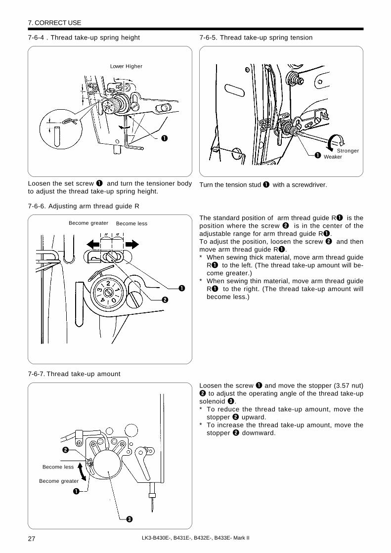
7-6-4 . Thread take-up spring height 7-6-5. Thread take-up spring tension
Loosen the set screw q and turn the tensioner bodyto adjust the thread take-up spring height.
Turn the tension stud q with a screwdriver.
7-6-6. Adjusting arm thread guide R
The standard position of arm thread guide Rq is theposition where the screw w is in the center of theadjustable range for arm thread guide Rq.To adjust the position, loosen the screw w and thenmove arm thread guide Rq.* When sewing thick material, move arm thread guide
Rq to the left. (The thread take-up amount will be-come greater.)
* When sewing thin material, move arm thread guideRq to the right. (The thread take-up amount willbecome less.)
7-6-7. Thread take-up amount
Loosen the screw q and move the stopper (3.57 nut)w to adjust the operating angle of the thread take-upsolenoid e.* To reduce the thread take-up amount, move the
stopper w upward.* To increase the thread take-up amount, move the
stopper w downward.
7. CORRECT USE
Become greater
Become less
28LK3-B430E-, B431E-, B432E-, B433E- Mark II
Turn off the power switch at the following times, otherwise the machine may operate if the footswitch is depressed by mistake, which could result in injury.• Threading• When replacing the needle• When not using the machine and when leaving the machine unattended.
Do not touch any of the moving parts or press any objects against the machine while sewing, asthis may result in personal injury or damage to the machine.
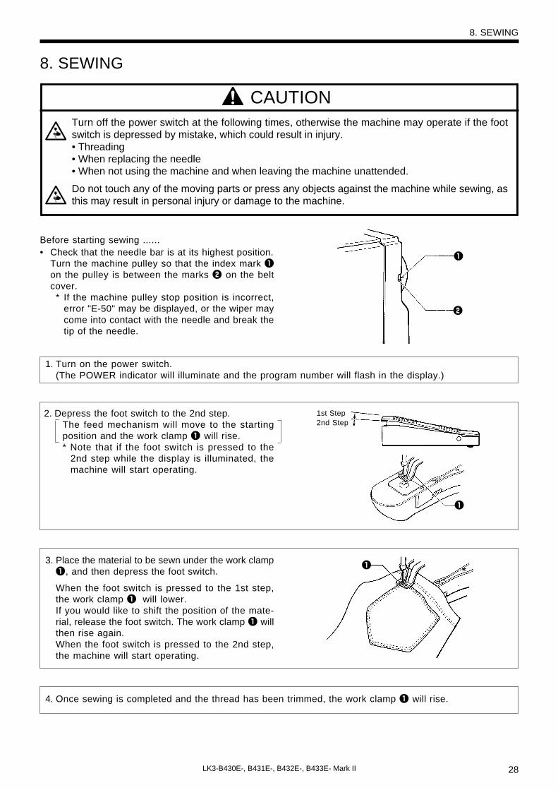
4. Once sewing is completed and the thread has been trimmed, the work clamp q will rise.
1. Turn on the power switch.(The POWER indicator will illuminate and the program number will flash in the display.)
2. Depress the foot switch to the 2nd step.The feed mechanism will move to the startingposition and the work clamp q will rise.* Note that if the foot switch is pressed to the
2nd step while the display is illuminated, themachine will start operating.
3. Place the material to be sewn under the work clampq, and then depress the foot switch.
When the foot switch is pressed to the 1st step,the work clamp q will lower.If you would like to shift the position of the mate-rial, release the foot switch. The work clamp q willthen rise again.When the foot switch is pressed to the 2nd step,the machine will start operating.
1st Step2nd Step
q
q
CAUTION
8. SEWING
Before starting sewing ......• Check that the needle bar is at its highest position.
Turn the machine pulley so that the index mark qon the pulley is between the marks w on the beltcover.
* If the machine pulley stop position is incorrect,error "E-50" may be displayed, or the wiper maycome into contact with the needle and break thetip of the needle.
8. SEWING
w
q

29 LK3-B430E-, B431E-, B432E-, B433E- Mark II
r
9 . MAINTENANCE AND INSPECTION
9 . MAINTENANCE AND INSPECTION
CAUTIONTurn off the power switch before carrying out cleaning, otherwise the machine may operate if thefoot switch is pressed by mistake, which could result in injury.
Be sure to wear protective goggles and gloves when handling the lubricating oil and grease, sothat they do not get into your eyes or onto your skin, otherwise inflammation can result.Furthermore, do not drink the oil or eat the grease under any circumstances, as they can causevomiting and diarrhoea. Keep the oil out of the reach of children.
9-1 . Cleaning the rotary hook1. Pull the shuttle race cover toward you to open it,
and then remove the bobbin case.
2. Open the setting claw q in the direction indicatedby the arrow, and then remove the shuttle racebody w and the shuttle hook e.
3. Clean all the dust and thread ends from aroundthe driver r, the top of the rotary hook threadguide and the shuttle race.
q
e w
30LK3-B430E-, B431E-, B432E-, B433E- Mark II
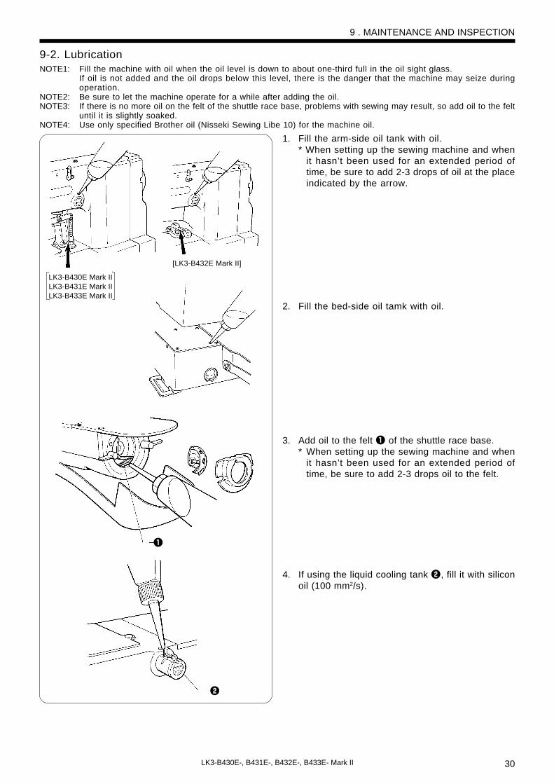
9-2. LubricationNOTE1: Fill the machine with oil when the oil level is down to about one-third full in the oil sight glass.
If oil is not added and the oil drops below this level, there is the danger that the machine may seize duringoperation.
NOTE2: Be sure to let the machine operate for a while after adding the oil.NOTE3: If there is no more oil on the felt of the shuttle race base, problems with sewing may result, so add oil to the felt
until it is slightly soaked.NOTE4: Use only specified Brother oil (Nisseki Sewing Libe 10) for the machine oil.
1. Fill the arm-side oil tank with oil.* When setting up the sewing machine and when
it hasn’t been used for an extended period oftime, be sure to add 2-3 drops of oil at the placeindicated by the arrow.
2. Fill the bed-side oil tamk with oil.
3. Add oil to the felt q of the shuttle race base.* When setting up the sewing machine and when
it hasn’t been used for an extended period oftime, be sure to add 2-3 drops oil to the felt.
4. If using the liquid cooling tank w, fill it with siliconoil (100 mm2/s).
9 . MAINTENANCE AND INSPECTION
q
w
LK3-B430E Mark IILK3-B431E Mark IILK3-B433E Mark II
[LK3-B432E Mark II]

31 LK3-B430E-, B431E-, B432E-, B433E- Mark II
9 . MAINTENANCE AND INSPECTION
q
9-3 . Draining the oil1. Remove and empty the waste oil container q
whenever it is full.2. After emptying the waste oil container q, screw it
back into its original position.
9-4 . Cleaning the control box air inlet portUse a vacuum cleaner to clean the filter in the air inletport w of the control box q at least once a month.
* If the machine is used while the air inlet port isblocked, the inside of the control box will overheat.When this happens, the overheating error code (“E-d0”) will be displayed and you will not be able tooperate the sewing machine.
9-5 . Cleaning the eye guardWipe the eye guard clean with a soft cloth.NOTE:
Do not use solvents such as kerosene or thinner to cleanthe eye guard.
9-6 . Checking the needleAlways check that the tip of the needle is not brokenand also the needle is not bent before starting sew-ing.
w
q

32LK3-B430E-, B431E-, B432E-, B433E- Mark II
Maintenance and inspection of the sewingmachine should only be carried out by a quali-fied technician.
Ask your Brother dealer or a qualified electri-cian to carry out any maintenance and inspec-tion of the electrical system.
Turn off the power switch and disconnect thepower cord from the wall outlet at the follow-ing times, otherwise the machine may oper-ate if the foot switch is depressed by mistake,which could result in injury.· When carring out inspection, adjustment andmaintenance
· When replacing consumable parts such asthe rotary hook and knife
Hold the machine head with both handswhen tilting it back or returning it to its origi-nal position. Furthermore, after tilting backthe machine head, do not push the faceplate side or the pulley side from above, asthis could cause the machine head to toppleover, which may result in personal injury ordamage to the machine.
If the power switch needs to be left on whencarrying out some adjustment, be extremelycareful to observe all safety precautions.
If any safety devices have been removed,be absolutely sure to re-install them to theiroriginal positions and check that they op-erate correctly before using the machine.
10 . STANDARD ADJUSTMENTS
10 . STANDARD ADJUSTMENTS
q
a A
(DP × 5) DP × 17
w
e
e
CAUTION
10-1 . Adjusting the needle bar height
Turn the machine pulley to move the needle bar to the lowest position. Then remove the rubber plug w,loosen the set screw e and then move the needle bar up or down to adjust so that the second reference linefrom the bottom of the needle (reference line A) is aligned with the lower edge of the needle bar bush q.* If using a DP × 5 needle, use the highest reference line (reference line a).
10-2 . Adjusting the needle bar lift amount
Adjust the needle bar lift amount as described below so that the tip of the rotary hook is aligned with thecenter of the needle when the machine pulley is turned to raise the needle bar from its lowest position untilthe lowest reference line on the needle (reference line B) is aligned with the lower edge of the needle bar bushq.* If using a DP × 5 needle, use the second reference line from the top of the needle (reference line b ).1. Open the support w in the direction of the arrow, and remove the felt support e.2. Loosen the screw r , and move the driver to adjust so that the tip of the rotary hook is aligned with the
needle center line.* When returning the felt support e, place it as shown in the illustration so as not to clamp the felt t, and
then gently press the felt t and the wick y until they are at the same height as the rotary hook race.* Return the support w to its original position.
q
b B
(DP × 5) DP × 17 t
r
w
e
y
t
t
q
q

33 LK3-B430E-, B431E-, B432E-, B433E- Mark II
1
0.01 - 0.08mm
Tip
Needle center line
10-3 . Adjusting the driver needle guard
Turn the machine pulley to align the tip of the rotary hook with the needle center line. Then loosen the setscrew w and turn the eccentric shaft e to adjust so that the driver needle guard q contacts the needle.If the needle contact pressure is too great, skipped stitches may occur. On the other hand, if the driver needleguard qis not touching the needle, the tip of the inner rotary hook will obstruct the needle, resulting in anexcessively high amount of friction.
10-4 . Adjusting the needle clearance
Turn the machine pulley to align the tip of the rotary hook with the needle center line. Then loosen the setscrew q and turn the eccentric shaft w to adjust so that the clearance between the needle and the rotary hookis 0.01 - 0.08 mm.
10-5 . Adjusting the shuttle race thread guide
Install the shuttle race thread guide q by pushing it in the direction of the arrow so that the needle groove isaligned with the center of the needle plate hole.NOTE:
If the shuttle race thread guide is in the wrong position, thread breakages, soiled thread or catching of the thread mayoccur.
10 . STANDARD ADJUSTMENTS
w
q
ew
q
34LK3-B430E-, B431E-, B432E-, B433E- Mark II
q
q
e
w
r
q
B
A
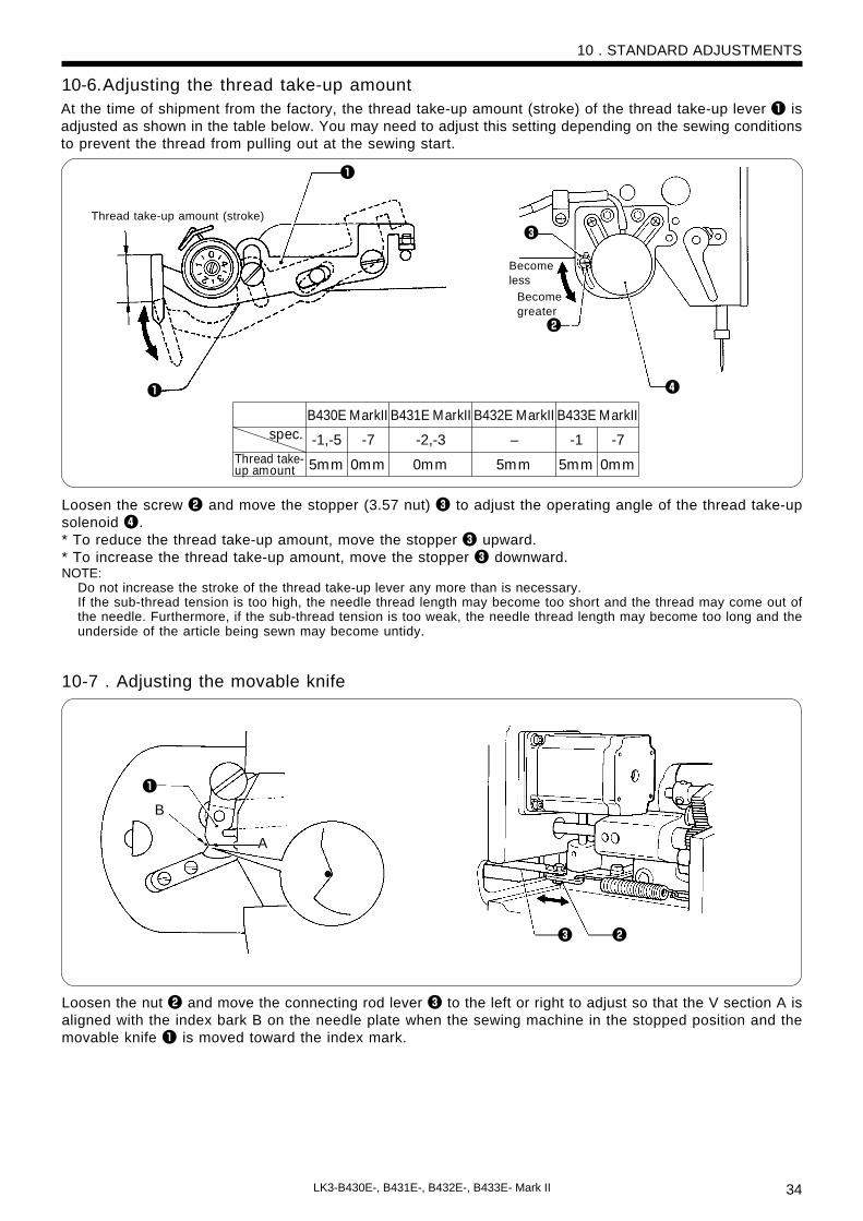
10-6.Adjusting the thread take-up amount
10-7 . Adjusting the movable knife
10 . STANDARD ADJUSTMENTS
e w
Thread take-up amount (stroke)
Becomeless
Becomegreater
Loosen the screw w and move the stopper (3.57 nut) e to adjust the operating angle of the thread take-upsolenoid r.* To reduce the thread take-up amount, move the stopper e upward.* To increase the thread take-up amount, move the stopper e downward.NOTE:
Do not increase the stroke of the thread take-up lever any more than is necessary.If the sub-thread tension is too high, the needle thread length may become too short and the thread may come out ofthe needle. Furthermore, if the sub-thread tension is too weak, the needle thread length may become too long and theunderside of the article being sewn may become untidy.
Loosen the nut w and move the connecting rod lever e to the left or right to adjust so that the V section A isaligned with the index bark B on the needle plate when the sewing machine in the stopped position and themovable knife q is moved toward the index mark.
At the time of shipment from the factory, the thread take-up amount (stroke) of the thread take-up lever q isadjusted as shown in the table below. You may need to adjust this setting depending on the sewing conditionsto prevent the thread from pulling out at the sewing start.
spec.
Thread take-up amount
B431E MarkII B432E MarkII B433E MarkII
-2,-3 –-7
0mm
-7
0mm
-1
B430E MarkII
-1,-5
0mm 5mm 5mm5mm

35 LK3-B430E-, B431E-, B432E-, B433E- Mark II
q w
e
rt
y
o
!1
!0
y
u
i
!0
!3
10-7-1 . Replacing the movable knife and fixed knife
1. Open the large shuttle hook cover, remove the screws q and w, and then remove the feed plate e.2. Remove the two screws r and the two screws t, and then remove the needle plate y.3. Remove the thread trimmer connecting rod u from the connecting rod lever pin i.
4. Remove the movable knife o and replace it with a new one. At this time, check that the movable knife oand the fixed knife !0 cut the thread cleanly. If necessary, adjust by using the appropriate movable knifewasher !1 (supplied as accessories).* Apply grease to the outside of the collar !2 at this time.
5. Install the fixed knife !0 at a distance of 0.5 mm from the needle hole plate !3.6. Place the thread trimming connecting rod uonto the connecting rod lever pin i, and then install to the
needle plate y.
10 . STANDARD ADJUSTMENTS
0.5mm
!2

36LK3-B430E-, B431E-, B432E-, B433E- Mark II
10-7-2. Adjusting the engagement of the movable knife and fixed knife
A. After the movable knife and fixed knife are properly engaged, tighten the screw as shown in Fig.1.B. Turn the movable knife (in the direction of the arrow) while the screw is still tightened.C. Loosen the screw.D. Turn the movable knife (in the direction of the arrow) while the screw is still loosened.Repeat above steps A, B, C and D four or five times to maintain the cutting performance of the knife.
A B C D
Cuttingedge
Movable knife
Fix knife
17mm
e
w
qr
10-8 . Adjusting the work clamp lift amount
The maximum work clamp lift amount is 17 mm from the top of the needle plate.The lift amount for each model is adjusted as shown in the table at the time of shipment.
1. To adjust the work clamp lift amount, loosen the bolt q and move the presser arm lever plate w up ordown.
2. Apply grease to the bottom of the presser plate e to the top of the presser arm lever plate w and to thesliding part of the work clamp (grease is already applied at the time of shipment), and check that themovement becomes easier.
3. Check that there is a gap between the presser arm lever plate w and the presser plate e when the presserfoot is lowered.* If movement is sluggish when the work clamp is being raised and lowered, it may not be possible to
increase the work clamp lift amount.* If the work clamp cannot be raised or lowered, error code “E-61” or “E-63” will be displayed.
10 . STANDARD ADJUSTMENTS
Fig. 1
Cuttingedge
Cuttingedge
Cuttingedge
[B430E-, B431E-, B433E MarkII]
-2,-3
10 mm+10Lift amount
-1,-5
10 mm
-2
14 mm
-7
9 mm
spec.
+10
+10
+10
-1
10 mm
-2
14 mm
-7
9 mm
B431E Mark IIB430E Mark II B433E Mark II
+10
+10
+10

37 LK3-B430E-, B431E-, B432E-, B433E- Mark II
[B432E Mark II]The maximum work clamp lift amount is 17 mm from the top of the needle plate when the machine isstopped. The lift amount is adjusted 13+1
0 mm at the time of shipment.
While the machine is stopped, loosen the bolt q and move the presser roller attachment plate w vertically toadjust the lift amount.* When making this adjustment, check to see if the work clamp will open. Also, readjust the closing distance
of the work clamp according to the second procedure of “10-10. Work clamp closing-distance adjustment”.* Loosen the nut t and turn the stop lever adjusting screw y to adjust the position of the stop lever e so that it does
not touch the adjusting ring r when the presser foot is raised.* If the work clamp cannot be raised or lowered, error code “E-61” or “E-63” will be displayed.
10-9.Work clamp pressure adjustment(B432E Mark II)Loosen the lower adjusting ring q as much as pos-sible (to the extent that the material being sewn doesnot slip and alter the pattern). Then, adjust the pres-sure by turning the upper adjusting ring w.
* Removal of the work clamp springLower the work clamp, then place the adjusting ringe in the hole of the frame, remove the tip of theadjusting screw from the lever holder r, and re-move the work clamp spring t.
w
q
w
q
r
e
t
10 . STANDARD ADJUSTMENTS
17mm
y
t
e r
38LK3-B430E-, B431E-, B432E-, B433E- Mark II
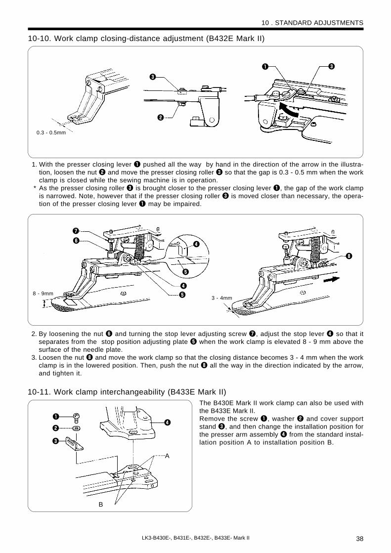
10-10. Work clamp closing-distance adjustment (B432E Mark II)
1. With the presser closing lever q pushed all the way by hand in the direction of the arrow in the illustra-tion, loosen the nut w and move the presser closing roller e so that the gap is 0.3 - 0.5 mm when the workclamp is closed while the sewing machine is in operation.
* As the presser closing roller e is brought closer to the presser closing lever q, the gap of the work clampis narrowed. Note, however that if the presser closing roller e is moved closer than necessary, the opera-tion of the presser closing lever q may be impaired.
2. By loosening the nut y and turning the stop lever adjusting screw u, adjust the stop lever r so that itseparates from the stop position adjusting plate t when the work clamp is elevated 8 - 9 mm above thesurface of the needle plate.
3. Loosen the nut i and move the work clamp so that the closing distance becomes 3 - 4 mm when the workclamp is in the lowered position. Then, push the nut i all the way in the direction indicated by the arrow,and tighten it.
0.3 - 0.5mm
e
w
q e
8 - 9mm
u
y
r
t
r
t
3 - 4mm
i
q
w
e
r
A
B
10 . STANDARD ADJUSTMENTS
10-11. Work clamp interchangeability (B433E Mark II)The B430E Mark II work clamp can also be used withthe B433E Mark II.Remove the screw q, washer w and cover supportstand e, and then change the installation position forthe presser arm assembly r from the standard instal-lation position A to installation position B.
39 LK3-B430E-, B431E-, B432E-, B433E- Mark II
2±0.5mm
q
we
Approx.20mm
r
t
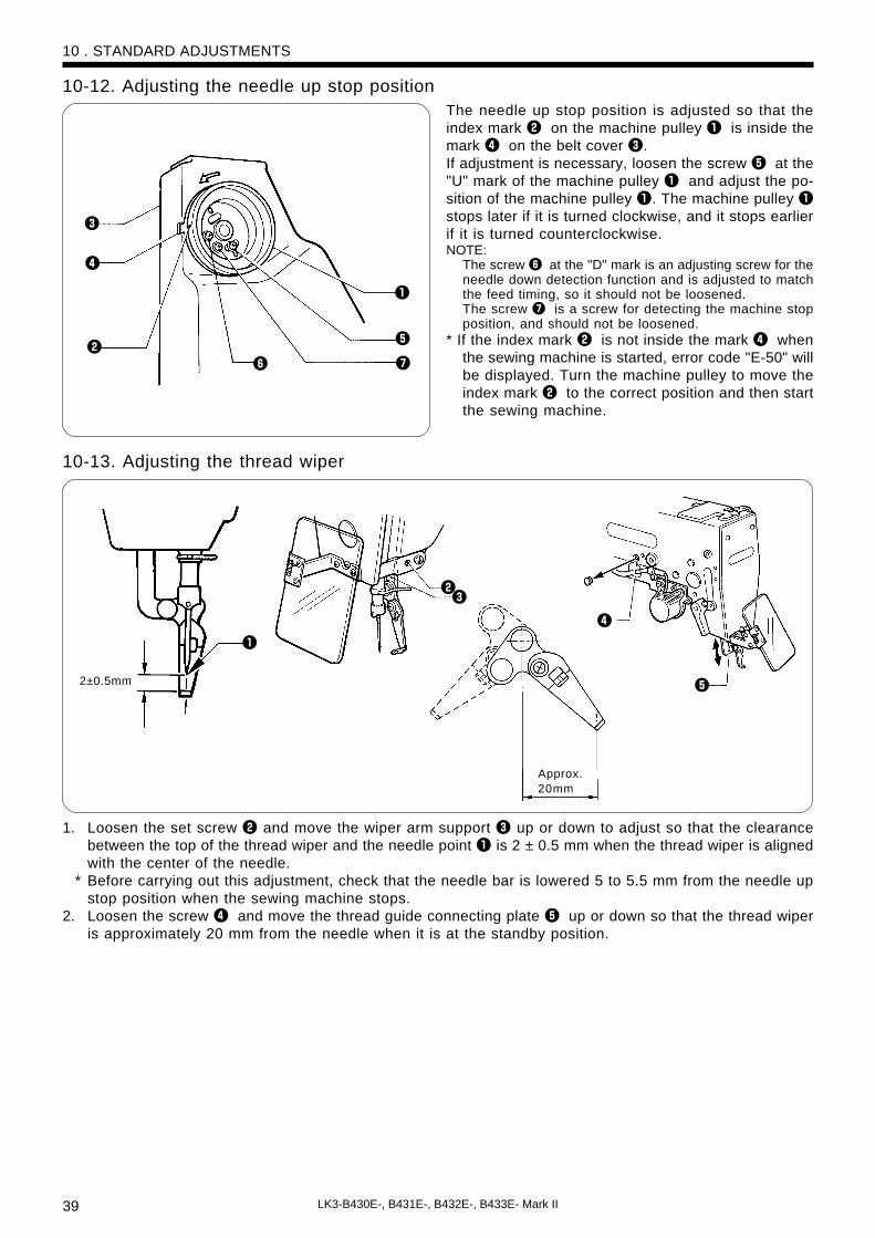
10-12. Adjusting the needle up stop positionThe needle up stop position is adjusted so that theindex mark w on the machine pulley q is inside themark r on the belt cover e.If adjustment is necessary, loosen the screw t at the"U" mark of the machine pulley q and adjust the po-sition of the machine pulley q. The machine pulley qstops later if it is turned clockwise, and it stops earlierif it is turned counterclockwise.NOTE:
The screw y at the "D" mark is an adjusting screw for theneedle down detection function and is adjusted to matchthe feed timing, so it should not be loosened.The screw u is a screw for detecting the machine stopposition, and should not be loosened.
* If the index mark w is not inside the mark r whenthe sewing machine is started, error code "E-50" willbe displayed. Turn the machine pulley to move theindex mark w to the correct position and then startthe sewing machine.
10-13. Adjusting the thread wiper
1. Loosen the set screw w and move the wiper arm support e up or down to adjust so that the clearancebetween the top of the thread wiper and the needle point q is 2 ± 0.5 mm when the thread wiper is alignedwith the center of the needle.
* Before carrying out this adjustment, check that the needle bar is lowered 5 to 5.5 mm from the needle upstop position when the sewing machine stops.
2. Loosen the screw r and move the thread guide connecting plate t up or down so that the thread wiperis approximately 20 mm from the needle when it is at the standby position.
10 . STANDARD ADJUSTMENTS
uw
q
e
r
t
y

40LK3-B430E-, B431E-, B432E-, B433E- Mark II
1. When the X-SCALE indicator q is illuminated and the RESET switch e is pressed while the TEST switch wis being pressed, the state of the X home position signal will appear on the display window r.
· When sensor is ON · When sensor is OFF
2. Each time the SELECT switch t is pressed, a different indicator will illuminate and the operating conditionfor the corresponding item will appear on the display window r.· When X-SCALE indicator is illuminated ...... X home position sensor (ON when home position detected)· When Y-SCALE indicator is illuminated ...... Y home position sensor (ON when home position detected)· When SPEED indicator is illuminated ......... Synchronizer ( * 1)· When COUNTER indicator is illuminated ... Presser sensor (ON when presser is lowered)· When PROGRAM NO. indicator is illuminated ... Work clamp closed sensor (ON when work clamp is open
[B432E Mark II only])
* 1 The synchronizer display simultaneously displays the needle up signal (3rd digit), the 24-section signal (2nd digit) and the needle down signal (1st digit).
[ H L L] “H” when the sensor is on, and “L” when the sensor is off Needle down signal 24-section signal Needle up signal
If the DIP switches at the side of the operation panel are changed at this time, the number of the DIP switchwhich was changed will be displayed in the 4th digit position of the display window r for about onesecond.
NOTE:The DIP switch can be changed at this time without turning off the power so that you can check the DIP switch input.However, you should normally always turn off the power when changing DIP switch settings.
3. Press the TEST switch w again to return the display to the normal condition.
S E L E C T
PROGRAM NO.
R E S E T
COUNTER
X-SCALE
Y-SCALE
SPEED
P
T E S T
BOBBIN.WIND
P4P3
P1 P2POWER
B430E Series
e
w
t
r
q
10-14. Checking the input sensor and DIP switch input
10 . STANDARD ADJUSTMENTS

41 LK3-B430E-, B431E-, B432E-, B433E- Mark II
10 . STANDARD ADJUSTMENTS
S E L E C T
PROGRAM NO.
R E S E T
COUNTER
X-SCALE
Y-SCALE
SPEED
P
T E S T
BOBBIN.WIND
P4P3
P1 P2POWER
B430E Series
r
e t
200V
220V
230V
100V380V400V415V
Display
[090 - 110]
[100 - 120]
[105 - 125]
[100 - 120]
Notes
“100” is displayed when the input voltage is 200 V.
“110” is displayed when the input voltage is100V (for 100-V spece.), 380V (for 380-V spece.),400V (for 400-V spece.)or 415V (for 415-V spece.).
Specifications
w
q
10-15. Checking the input voltage
1. Turn on the power switch.2. Press the SELECT switch q until the Y-SCALE indicator w illuminates.3. While pressing the TEST switch e, press the RESET switch r.4. If the input voltage is normal, the input voltage conditions will be shown in the display window t as
indicated in the table above.5. Press the TEST switch e again to return the display to the normal condition.
10-16. Clearing all memory settingsIf the sewing machine stops operating normally, the cause may be that an incorrect memory setting may havebeen made by means of the memory switch, for instance. In such cases, carry out the following procedure toclear the memory, and also check the DIP switch settings.[ Method ]While pressing the RESET switch, turn on the power. This will clear all of the memory setting.NOTE
• This operation causes all settings stored in memory such as memory switch and user program settings to be cleared.• If the optional emergency stop switch has been installed, you should reset memory switch No. 10 to ON.
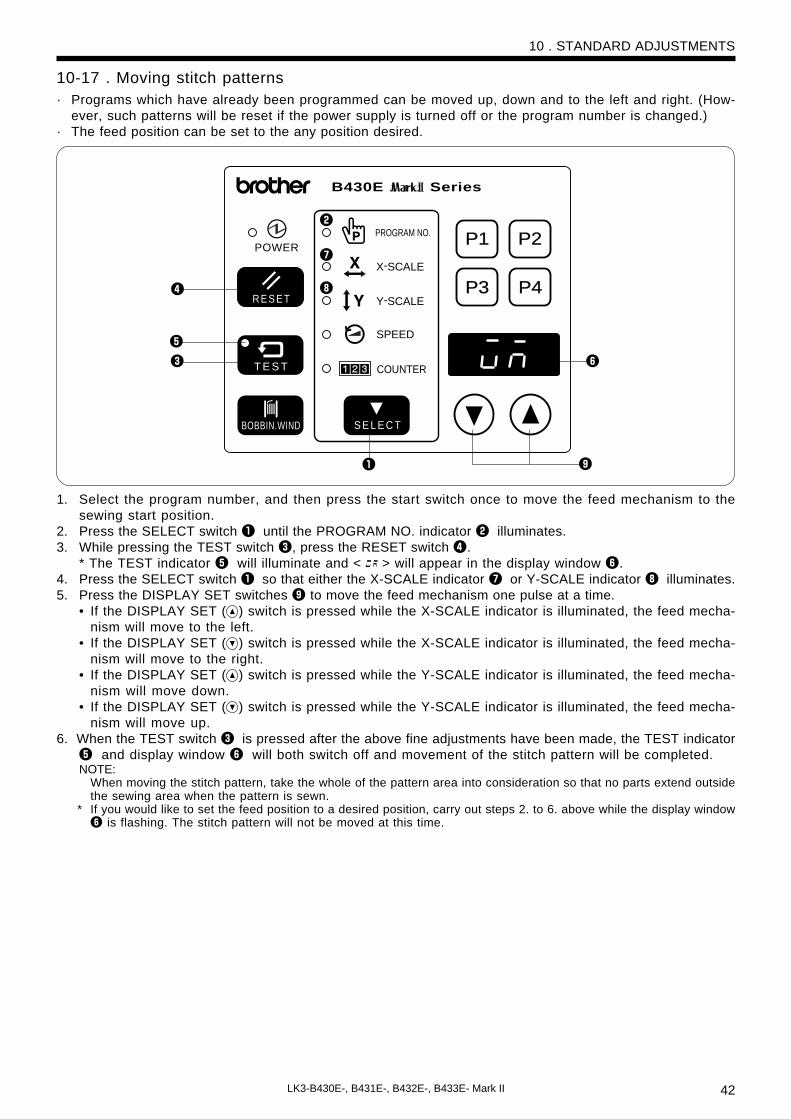
42LK3-B430E-, B431E-, B432E-, B433E- Mark II
S E L E C T
PROGRAM NO.
R E S E T
COUNTER
X-SCALE
Y-SCALE
SPEED
P
T E S T
BOBBIN.WIND
P4P3
P1 P2
B430E Series
POWER
r
e
q
y
t
o
w
u
i
10-17 . Moving stitch patterns· Programs which have already been programmed can be moved up, down and to the left and right. (How-
ever, such patterns will be reset if the power supply is turned off or the program number is changed.)· The feed position can be set to the any position desired.
1. Select the program number, and then press the start switch once to move the feed mechanism to thesewing start position.
2. Press the SELECT switch q until the PROGRAM NO. indicator w illuminates.3. While pressing the TEST switch e, press the RESET switch r.
* The TEST indicator t will illuminate and < > will appear in the display window y.4. Press the SELECT switch q so that either the X-SCALE indicator u or Y-SCALE indicator i illuminates.5. Press the DISPLAY SET switches o to move the feed mechanism one pulse at a time.
• If the DISPLAY SET ( ) switch is pressed while the X-SCALE indicator is illuminated, the feed mecha-nism will move to the left.
• If the DISPLAY SET ( ) switch is pressed while the X-SCALE indicator is illuminated, the feed mecha-nism will move to the right.
• If the DISPLAY SET ( ) switch is pressed while the Y-SCALE indicator is illuminated, the feed mecha-nism will move down.
• If the DISPLAY SET ( ) switch is pressed while the Y-SCALE indicator is illuminated, the feed mecha-nism will move up.
6. When the TEST switch e is pressed after the above fine adjustments have been made, the TEST indicatort and display window y will both switch off and movement of the stitch pattern will be completed.NOTE:
When moving the stitch pattern, take the whole of the pattern area into consideration so that no parts extend outsidethe sewing area when the pattern is sewn.
* If you would like to set the feed position to a desired position, carry out steps 2. to 6. above while the display windowy is flashing. The stitch pattern will not be moved at this time.
10 . STANDARD ADJUSTMENTS

43 LK3-B430E-, B431E-, B432E-, B433E- Mark II
11. USING THE COUNTERS11-1 . Using the bobbin thread counter
S E L E C T
PROGRAM NO.
R E S E T
COUNTER
X-SCALE
Y-SCALE
SPEED
P
T E S T
BOBBIN.WIND
P4P3
P1 P2POWER
B430E Series
r
e y
tq
S E L E C T
PROGRAM NO.
R E S E T
COUNTER
X-SCALE
Y-SCALE
SPEED
P
T E S T
BOBBIN.WIND
P4P3
P1 P2POWER
B430E Series
r
e y
q u
w
t
w
1. Press the SELECT switch q until the COUNTERindicator w illuminates.
2. While pressing the TEST switch e, press the RE-SET switch r.* The COUNTER indicator w will flash and the
counter will switch to bobbin thread counter set-ting mode.
3. Press the DISPLAY SET switches t to set the num-ber of articles to be sewn.• The bobbin thread counter can be set to sew a
number of articles from one (“0001”) through to9999 (“9999”).If the bobbin thread counter is set to “0000”,
sewing is carried out without the number of ar-ticles sewn being counted.
• If you press the RESET switch r while settingthe bobbin thread counter, the setting will returnto “0000”.
4. Press the TEST switch e.* The number displayed in the display window y
will then be stored as the bobbin thread countersetting.
11-2 .Using the production counter
1. Press the SELECT switch q until the SPEED indi-cator w illuminates.
2. While pressing the TEST switch e , press the RE-SET switch r .* The COUNTER indicator t and the SPEED indi-
cator w will i l luminate, and the productioncounter will be displayed in the display windowy.
• Press the RESET switch r to reset the produc-tion counter to “0000”.
• You can also press the DISPLAY SET switchesu to set the production counter to the desiredvalue.
3. When the foot switch is depressed, the sewing ma-chine will start sewing.
4. If you press the TEST switch e or the SELECTswitch q, the display will return to showing thebobbin thread counter.
11 . USING THE COUNTERS
5. Each time the sewing of a single article is completed, the number being displayed in the display window ywill become smaller. When the number of articles set by the bobbin thread counter have all been sewn,“0000” will be displayed in the display window y, and an alarm will start sounding continuously.* The sewing machine will not operate during this time, even if the foot switch is depressed.
6. Replace the bobbin, and then press the RESET switch r.* The alarm will then stop sounding, and the number which was set in step 3. above will be re-displayed in
the display window y.
The production counter can be displayed in the display window y separately from the bobbin thread counter.
If you use the bobbin thread counter to set the number of articles which can be sewn with the amount ofbobbin thread available, you can stop the bobbin thread running out in the middle of sewing a pattern.
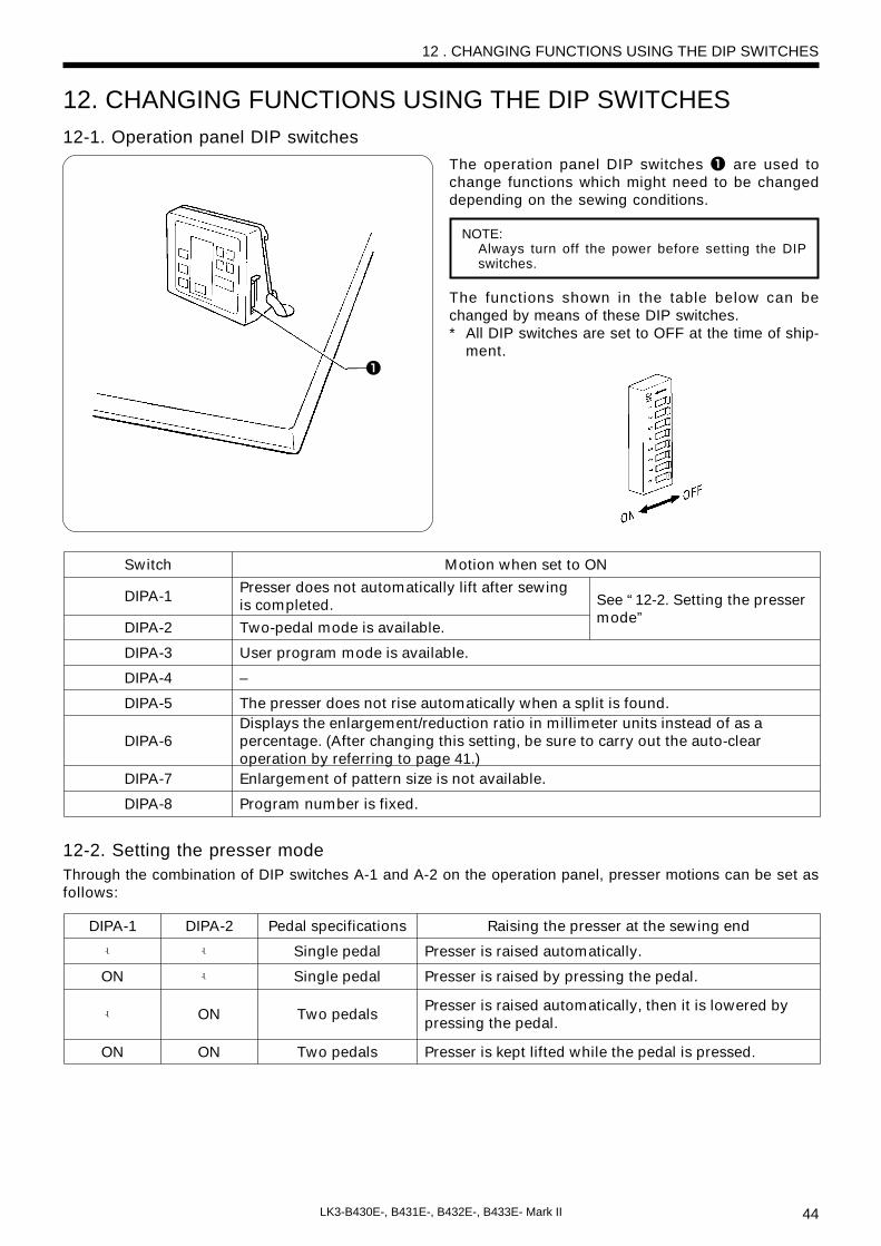
44LK3-B430E-, B431E-, B432E-, B433E- Mark II
q
DIPA-1
DIPA-2
DIPA-3
DIPA-4
DIPA-5
DIPA-6
DIPA-7
DIPA-8
Motion when set to ON
See “12-2. Setting the presser mode”
Presser does not automatically lift after sewing is completed.
Two-pedal mode is available.
User program mode is available.
–
The presser does not rise automatically when a split is found.Displays the enlargement/reduction ratio in millimeter units instead of as a percentage. (After changing this setting, be sure to carry out the auto-clear operation by referring to page 41.)Enlargement of pattern size is not available.
Program number is fixed.
Switch
-�
ON
-�
ON
DIPA-2
-�
-�
ON
ON
Pedal specifications
Single pedal
Single pedal
Two pedals
Two pedals
Raising the presser at the sewing end
Presser is raised automatically.
Presser is raised by pressing the pedal.
Presser is raised automatically, then it is lowered by pressing the pedal.
Presser is kept lifted while the pedal is pressed.
DIPA-1
12. CHANGING FUNCTIONS USING THE DIP SWITCHES12-1. Operation panel DIP switches
The operation panel DIP switches q are used tochange functions which might need to be changeddepending on the sewing conditions.
NOTE:Always turn off the power before setting the DIPswitches.
The functions shown in the table below can bechanged by means of these DIP switches.* All DIP switches are set to OFF at the time of ship-
ment.
12-2. Setting the presser modeThrough the combination of DIP switches A-1 and A-2 on the operation panel, presser motions can be set asfollows:
12 . CHANGING FUNCTIONS USING THE DIP SWITCHES

45 LK3-B430E-, B431E-, B432E-, B433E- Mark II
q
DIPB-1
DIPB-2
DIPB-3
DIPB-4
DIPB-5
DIPB-6
DIPB-7
DIPB-8
Motion when set to ON
First two stitches are sewn at a low speed of 260 rpm.
Last two stitches are sewn at a low speed of 260 rpm.
–
Last two stitches are sewn at a low speed of 700 rpm.
First two stitches are sewn at a low speed of 400 rpm.
Low speed sewing is not performed at the start of sewing.
The motor operates in reverse when the upper shaft stops, to return the needle bar to close to its highest position. *NOTE
Area checking of the sewing data is not carried out.
Switch
DANGER
12-3 . DIP switches inside the control box
Wait at least 5 minutes after turning off the power switch and disconnecting the power cord fromthe wall outlet before opening the face plate of the control box. Touching areas where high volt-ages are present can result in severe injury.
The DIP switches q inside the control box are used tochange functions which do not often need to bechanged once they have been set.
The functions can be changed as shown in the tablebelow by changing the positions of the DIP switchesq.* All DIP switches are set to OFF at the time of ship-
ment.NOTE:
When opening the cover, hold it securely so that it doesnot fall down.
12 . CHANGING FUNCTIONS USING THE DIP SWITCHES
*NOTE:When the motor operates in reverse to raise the needle, the thread take-up will stop at a position which is lower thanits normal stopping position. As a result, the thread take-up will rise slightly at the sewing start, and this may result inthe thread pulling out under certain coditions.

46LK3-B430E-, B431E-, B432E-, B433E- Mark II
12-4. Using user programs
Recording a user program
12. Press the TEST switch w. This completes the recording.* The menu indicators ( e to i ) will all illuminate and “p1” will appear in the display to indicate that user program No.1 is currently
selected.
11. Press the SELECT switch e. * This completes the recording of user program No.1.
* “PP 2” will then appear in the display window o, to indicate that user program No.2 is now being recorded.
Repeat steps 3. through to 11. to record further programs as desired.
10. Press the DISPLAY SET switches !0 to select the speed setting that you would like to record.
9. Press the SELECT switch e. * The SPEED indicator u will illuminate.
8. Press the DISPLAY SET switches !0 to select the Y scale setting that you would like to record.
7. Press the SELECT switch e. * The Y-SCALE indicator y will illuminate.
6. Press the DISPLAY SET swithes !0 to select the X scale setting that you would like to record.
5. Press the SELECT switch e. * The X-SCALE indicator t will illuminate.
4. Press the DISPLAY SET switches !0 to select the number for the program that you would like to record.
3. Press the SELECT switch e .* The PROGRAM NO. indicator r will illuminate.
2. Turn on the power switch.While pressing the TEST switch w, press the SE-LECT switch e.
* All of the menu indicators (r to i) will illuminate and themode will switch to recording mode.
* In addition, “PP 1” will appear in the display window o toindicate that user program No.1 is being recorded. (Oncerecording of No.1 is completed, No.2 will be displayed; onceNo.2 is completed, No.3 will be displayed. Thus the nextunrecorded program letter is always displayed.)
q
!1
S E L E C T
PROGRAM NO.
R E S E T
COUNTER
X-SCALE
Y-SCALE
SPEED
P
T E S T
BOBBIN.WIND
P4P3
P1 P2POWER
B430E Series
o
!0e
w
!2
r
t
y
u
i
1. Turn off the power switch and then set DIP switchA-3 of the DIP switches q to ON.
12 . CHANGING FUNCTIONS USING THE DIP SWITCHES
User program ...It can store sixteen different programs which can include details such as the program number, X scale, Yscale and sewing speed. If you are sewing certain patterns over and aver again, it is useful to record thesettings for these patterns into a user program.

47 LK3-B430E-, B431E-, B432E-, B433E- Mark II
Clearing the user programs
2. Depress the foot switch to the second step.
3. Check the sewing pattern (see P.22), and then sew the pattern selected.
1. Switch the machine to recording mode by the procedure in steps 2. of recording a user program.
2. Use the DISPLAY SET switches !0 to specify the user program number which is to be cleared of data.
3. Press the RESET switch !2 .* The buzzer will sound and the user program with the number selected will be cleared.* If you press and hold the RESET switch !2 until after the buzzer has sounded twice, all user programs
will be cleared.NOTE:
If data has been recorded in user programs P1, P2, P3 and P4 and you then clear the data in user program P2, thecontents of P3 will be transferred to P2, and the contents of P4 will be transferred to P3.
1. Press the DISPLAY SET switches !0 to select the speed program number for the user program that youwould like to use.
*The user program numbers P1 to P4 can also be selected using the user program switches !1.
Using a user program
12 . CHANGING FUNCTIONS USING THE DIP SWITCHES

48LK3-B430E-, B431E-, B432E-, B433E- Mark II
memo-00
memo-01
memo-02
memo-03
memo-04
memo-05
memo-06memo-07memo-08
memo-09
memo-0Amemo-0b
memo-0c
memo-0d
memo-0E
memo-0F
Motion when set to ON
At the end of sewing, the feed plate will be returned to the sewing start point via mechanical home position.
Work clamp will move to the sewing start point, and then will be lifted.(The work clamp rises at the final stitch to enable the quick taking out of the workpieces.)
Feed will move automatically to the next starting point at the same time as a user program is switched. (Normally it moves to the starting point after sewing starts.)
When sewing using programs, the programs which have been set will be sewn in numerical order. (Cycle sewing mode is set.)
The sewing speed will be fixed at the minimum speed for the maximum pitch of the sewing data.(Set this to ON if you are concerned that vartations in pitch may cause changes in the sewing speed.)
Increases the presser solenoid lifting force (Set to ON when using the optional spring for extra-heavy material)
Enlargement and reduction ratio settings for X and Y become the same.–Test feeding is carried out stitch by stitch when the foot switch is depressed.
The sewing start point becomes the reference point for enlargements and reductions.(The reference point for enlargements and reductions is normally the center of the sewing frame.)
Work clamp does not close.Work clamp closes when it is lower.
Needle stops in up position during emergency stop.(EMERGENCY STOP switch is available as an option.)
The bar tacking stitches (with a pitch of less than 1 mm) are also enlarged and reduced. (Normally stitches with a pitch of less than 1 mm are not enlarged or reduced.)
Test feeding will be performed at the same speed as that for actual sewing.(This is used for checking feeding operation.)
After sewing is finished, the work clamp automatically opens and closes once (practice operation).
Switch
* *
S E L E C T
PROGRAM NO.
R E S E T
COUNTER
X-SCALE
Y-SCALE
SPEED
P
T E S T
BOBBIN.WIND
P4P3
P1 P2POWER
B430E Series
r
t
w
q
e
13. CHANGING SPECIAL FUNCTIONS USING THE MEMORY SWITCHESThe functions of the switches on the operation panel q can be changed to carry out special functions.NOTE:
After changing the memory switch settings, press the power switch to turn the power off and then back on again.The memory switches “00 - 2F” are set to OFF at the time of shipment.
1. Turn on the power switch.2. While pressing the TEST switch w, press the BOB-
BIN. WIND switch e. * “00 - - ” will appear in the display window r.
3. Press the DISPLAY SET switches t to set the twodigits at the left of the display window r to thecorresponding number (00 to 4F) of the functionshown in the table below that you would like toselect.
4. When the BOBBIN. WIND switch e is pressed, thetwo spaces at the right in the display window willchange from “ - - ” to “ON”.* If you press the RESET switch y at this time,
memory switches from 00 to 2F will all be set toOFF (“--”), and memory switches from 30 to 4Fwill be returned to their initial settings.
5. Press the TEST switch w .* The display will return to normal.
■ Memory switches 00 - 0F
13. CHANGING SPECIAL FUNCTIONS USING THE MEMORY SWITCHES
*B432E Mark II only.

49 LK3-B430E-, B431E-, B432E-, B433E- Mark II
13. CHANGING SPECIAL FUNCTIONS USING THE MEMORY SWITCHES
memo-11 - memo-13
memo-19
memo-1A
memo-1b
memo-14
memo-15
memo-16
memo-17
memo-18
memo-1F
Motion when set to ON
—
Presser position errors are not detected.
Needle up stop position errors are not detected.
Presser can be moved up and down before the home position is detected.(Normally the presser cannot be moved up and down until after the home position has been detected.)
Solenoid wiper can be used (available as an option).
—
Needle cooler output is enabled. (Needle cooler is available by special order.)
Thread take-up device is not operated at the sewing end.
Thread take-up device operates one stitch before the sewing end.
Thread is not trimmed when an emergency stop occurs during sewing. (EMERGENCY STOP switch is available as an option.)
Switch
memo-1c —
memo-1d —
memo-1E Errors can be reset using the EMERGENCY STOP switch. (EMERGENCY STOP switch is available as an option.)
memo-10 The optional emergency stop switch can be used.
memo-20
memo-21
Motion when set to ON
Machine head from previous B430E series is used. (Only the operation panel and box are Mark II.)
Rotating-type thread breakage detector operates. (Device is available by special order.)
Switch
memo-22 During thread breakage detection, sensitivity is decreased from 8 to 14 stitches at the sewing start. (Sensitivity during sewing is three stitches.)
memo-23 When DIP switch A-8 is simultaneously ON, setting values changed using the operation panel are ignored.
memo-24 - memo-2F —
memo-30
memo-31
memo-32
memo-33
memo-34
memo-35
memo-36
memo-37
memo-38
memo-39
memo-3A
memo-3b
memo-3c
memo-3d
memo-3E
memo-3F
memo-40-
memo-4F
Possible setting range
0 - 30
0 - 30
c :12 - 25 × 100rpm 25
/zx :12 - 27
1 - 10
0 - 5
3 - 9
—
1 - 20
1 - 20
1 - 20
1 - 20
1 - 20
—
—
—
—
—
Units
mm
mm
× 100rpm
× 7.5°
Needle
× 100rpm
—
× 7.5°
× 7.5°
× 7.5°
× 7.5°× 7.5°
—
—
—
—
—
Initial value
/zc:30x :12
/z :10x:3,c:30
27
5
0
4
—
10
10
10
10
10
—
—
—
—
—
Explanation
Limits the maximum area in the horizontal direction (X)
Limits the maximum area in the vertical direction (Y)
Changes the maximum sewing speed.
Changes the feed timing1 (Fast) ←5 (Standard) →10 (Slow)
The sewing speed at the sewing start is 400 rpm for the specified number of stiches.
Changes the sewing start speed specified by memo-34.
—
Changes the feed timing one stitch before the sewing end.1 (Fast) ←10 (Standard)→20 (Slow)
Changes the feed timing two stitches before the sewing end. �Changes the feed timing for the third stitch at the sewing start.1 (Fast) ←10 (Standard) →20 (Slow)
Changes the feed timing for the second stitch at the sewing start.
Changes the feed timing for the first stitch at the sewing start.
—
—
—
—
—
Switch
■ Memory switches 10 - 1F
■ Memory switches 20 - 2F
■ Memory switches 30 - 4F30 to 4F are set by entering two-digit values.These values are incremented using the P2 switch, and decremented using the P4 switch.
NOTE:/...B430E Mark II, z...B431E Mark II, x...B432E Mark II, c...B433E Mark II

50LK3-B430E-, B431E-, B432E-, B433E- Mark II
o
S E L E C T
PROGRAM NO.
R E S E T
COUNTER
X-SCALE
Y-SCALE
SPEED
P
T E S T
BOBBIN.WIND
P4P4P3
P1 P2P2POWER
B430E Series
!0
!1e
w
!2
r
t
y
u
i
q
13-1. Using the cycle sewing function
13. CHANGING SPECIAL FUNCTIONS USING THE MEMORY SWITCHES
What is the cycle sewing function?The cycle sewing function lets you program up to four patterns for cycle sewing of patterns in a predetermined order.
Recording a cycle sewing program
1. Set DIP switch q-3 to ON, and then record thepatterns which you would like to use for cyclesewing. (Refer to “12-4. Using user programs”.)
* Cycle sewing cannot be performed using patterns (P1 to P16)
which have not had a user program assigned.
2. Set the memo-03 switch to ON. (Refer to page 48for how to do this.)
3. While pressing the TEST switch w, press the SE-LECT switch e.
* All of the menu indicators (r to i) will illuminate and the
mode will switch to recording mode.
4. Press the P1 switch o.• “Pc 1” will appear in the display window !0 to
indicate that cycle sewing program No. 1 is be-ing recorded.
* Programs P2, P3 and P4 switches can also be used for pro-gramming.
5. Press the SELECT switch e. *The PROGRAM No. indicator r will illuminate and “1- -” will appear in the display window !0.
6. Press the DISPLAY SET switches !1 to select the number for the user program that you would like torecord.
7. Press the SELECT switch e. *“2- -” will appear in the display window !0.
8. Press the DISPLAY SET switches !1 to select the number for the user program that you would like torecord.
9. Repeat steps 5. and 6. to record all programs which you would like to include for cycle sewing.* After “9- -” is displayed, “A- -”, “b- -”, “c- -”, “d- -”, “E- -” and “F- -” will be displayed in that order so that up to the 15th pattern can
be recorded.* If you would like to return to a previous number during the recording procedure, press the P1 switch so that “Pc 1” is displayed, and
then return to step 4.
10. Press the TEST switch w.• This completes the setting of cycle sewing program No. 1.* The menu indicators (r to i) will all illuminate and “c1-1” will appear in the display window !0 to indicate that the cycle sewing
program No.1 is currently selected.
51 LK3-B430E-, B431E-, B432E-, B433E- Mark II
13. CHANGING SPECIAL FUNCTIONS USING THE MEMORY SWITCHES
1. When “c1-1” is flashing in the display window !0, press the foot switch to the second step.
2. Start sewing.
3. “c1-1”, “c1-2”, “c1-3” are sewn in order for each article, and when the last-recorded pattern has beensewn, the display returns to “c1-1".
* If you press one of the DISPLAY SET switches !1 when “c1-*” is displayed, you can return to the previous stitch pattern or skip astitch pattern.
* If you press the SELECT switch e when “c1-*” is displayed, you can check the contents of the recorded user program.
Using a cycle sewing program
Clearing a cycle sewing program
1. Switch the machine to recording mode by the procedure in step 3. of recording a user program.
2. Use one of the P* switches (user program switches) to specify which cycle sewing program to clear.* Press the P1 switch o if you would like to clear cycle sewing program No. 1. (“Pc 1” will be displayed.)
3. Press the RESET switch !2.* The recorded contents of the specified cycle sewing program will then be cleared.
* If you press and hold the RESET switch !2 until after the buzzer has sounded twice, all cycle sewing programs will be cleared.
NOTE:If you clear a user program after any cycle sewing programs have been recorded, all recorded cycle sewing programswill also be cleared.

52LK3-B430E-, B431E-, B432E-, B433E- Mark II
Wait at least 5 minutes after turning off the power switch and disconnecting the power cord fromthe wall outlet before opening the face plate of the control box. Touching areas where high volt-ages are present can result in severe injury.
Machine motor operation error.
E-13
E-20
E-21
E-30
E-32
E-31
E-40
E-41
E-42
E-50
E-60E-61E-62
E-64 Work clamp does not close.E-63
E-70
E-80
E-81
E-82
E-90
E-91
Cause
Machine specification select connector is not connected properly.
Problem with machine motor stopping, or synchronizer connection error.
Data is outside possible sewing area due to enlargement ratio setting.
The data format of the user program (% or mm) does not match the setting of DIP switch A-6.
After changing the setting of DIP switch A-6, clear all memory settings. (Refer to “10-16. Clearing all memory settings”.)
Stitch pattern data overlaps the sewing area when area limiting is active.
Length of a stitch exceeds 10 mm.
Abnormality in the sewing data.
Invalid program number specified.
Needle bar does not stop when the needle is raised.
Presser has not been lowered.Presser cannot be raised.Presser is not raised.Presser cannot be lowered.
Cooling fan does not operate.
Motor PROM is not correctly inserted.
Foot switch was depressed when the power was turned on.
An operation panel switch was depressed when the power was turned on.
Abnormal drop in power supply voltage, or power was turned on again immediately after it was turned off.
Abnormal rise in power supply voltage.
Remedy
Turn off the power and check if connectors P3 is disconnected.
Turn off the power, and then turn the machine pulley to check if the machine has locked up. Check the synchronizer connection. Check if connectors P11, P12 and P13 are disconnected.
Turn off the power and check the ground wire connection.
Press the RESET switch, and then set the enlargement ratio again.
Press the RESET switch, and then reset the memory switches “30” and “31” or enlargement ratio.
Press the RESET switch, and then set the enlargement ratio again.
If programming a new sewing data, repeat the procedure from the beginning.
Press the RESET switch and specify a correct number.
Turn the pulley to align the index mark with the needle up stop position. (Refer to “10-12. Adjusting the needle up stop position”.) Check the V-belt tension. (Refer to “3-14. Installing the V-belt”.)
Refer to “16. Troubleshooting”.Turn off the power and check the connection of presser sensor connector P1.
Turn off the power, and then check if the cooling fan is blocked with scraps of thread.
Turn off the power and check.
Turn off the power and check.
Turn off the power and check the operation panel. Check that all panel cords are normal.
Turn off the power and check the input voltage. After turning off the power, wait 3 seconds or more before turning it on again. (Refer to “10-15. Checking the input voltage”.)
Turn off the power and check the input voltage. (Refer to “10-15. Checking the input voltage”.)
Code
*
14. TABLE OF ERROR CODES
DANGER
If a malfunction should occur with the sewing machine, a buzzer will sound and an error code will appear inthe display window. Follow the remedy procedure to eliminate the cause of the problem.
14. TABLE OF ERROR CODES
*B432E Mark II only

53 LK3-B430E-, B431E-, B432E-, B433E- Mark II
E-10
E-11
E-12
E-14
Cause
Emergency stop switch was pressed.
Emergency stop switch was pressed during sewing.
Emergency stop switch is being continually pressed, or emergency switch connection error.
Thread breakage detected.
Remedy
Turn the EMERGENCY STOP switch clockwise to release the lock, and then press the RESET switch to reset the error.
Turn the EMERGENCY STOP switch clockwise to release the lock, and then press the RESET switch to reset the error. You can then press the STEP BACK switch to repeat the sewing.
Turn off the power and check.
Turn the EMERGENCY STOP switch clockwise to release the lock, and then press the RESET switch to reset the error. You can then press the STEP BACK switch to repeat the sewing.
Code
E-E2Corrupted EEPROM control information data.
Press the RESET switch to reset the error. However, the data (memory switches, display and user programs) will all be initialized.
E-A0
E-b0
E-d0
E-E0
E-F0
E-F1
E-F2
E-E1
Cause
Home position cannot be detected (malfunction of home position sensor), or malfunction of power supply circuit board.
You tried to change the program number when DIP switch A-8 was set to ON.
Heat sink of control circuit board is abnormally hot.
Malfunction of EEPROM (malfunction of main circuit board).
Solenoid short-circuit (malfunction of main circuit board), or power relay is not operating (malfunction of power supply circuit board).
Bad connection in cable between power supply circuit board and main circuit board.
Abnormal current detected in power supply circuit board.
Corrupted EEPROM data, or main PROM version has been upgraded.
Remedy
Turn off the power and check the connection of home position sensor connector P1.
Press the RESET switch.Set DIP switch A-8 to OFF before trying to change the program number.
Turn off the power and clean the air intake port of the box.
Turn off the power, and turn it back on. If the error continually occurs, contact a qualified service technician.
Turn off the power and contact a qualified service technician.
Turn off the power and check if connectors P16 is disconnected.
Turn off the power and contact a qualified service technician.
Press the RESET switch to reset the error. However, the data (memory switches, display and user programs) will be reset to the backup data or initialized.
Code
Panel display
Text display A b c d E F 6 H L o
REFERENCE segment LED alphabet
14. TABLE OF ERROR CODES
■ Errors generated when optional equipment is connected

54LK3-B430E-, B431E-, B432E-, B433E- Mark II
15. GAUGE PARTS LIST ACCORDING TO SUBCLASSESThe following are standard gauge parts according to each specification. (In the following table, parts marked with ★ are common with the LK3-B430E; parts with ✩ are common withthe BAS-311E.)
15. GAUGE PARTS LIST ACCORDING TO SUBCLASSES
B430E Mark II
-2 -5-1 -7
(φ2.2)S49980-001 FM
(φ2.6)S10212-101 E
(φ1.6)S10211-001 A
152690-301 B 159610-201 A159610-201 A
154340-001 B154339-001 A
154341-001 154341-001
S15667-001 LA
154342-001 B159612-001 A
159613-051159613-051
152687-902 B 152685-903 A152685-903 A
152686-101 B 152682-101 A
107606-001 104525-001
144588-001 B 145519-001
S15902-401 LA S15902-401 LA
154339-001 A
S16074-101 LAS16074-101 LA
159612-001 A
S16492-101 LA
S15667-001 LA
S15665-001 LA
S15663-991 LB S15662-992 LA
Spring, anti-spin
Screw
Tension spring
SpecificationPart name
Needle hole plate
Bobbin case assy
Bobbin
Shuttle hook
Large shuttle hook
Spring tension
Spring ★
★
★
★★
★
★
★
★
★
★
★
★
★
★
✩
✩
★
★
★
★
★
✩
✩
★
✩
✩
✩
✩
★
✩
✩
✩
✩
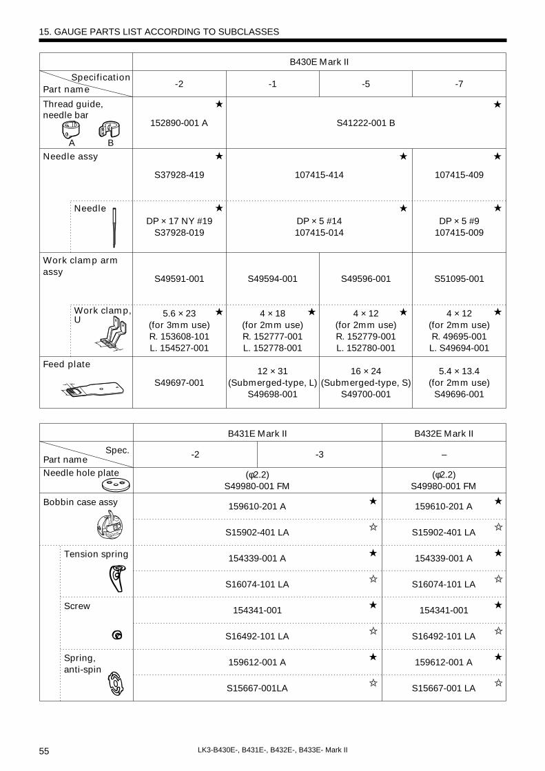
55 LK3-B430E-, B431E-, B432E-, B433E- Mark II
15. GAUGE PARTS LIST ACCORDING TO SUBCLASSES
A B
B430E Mark II
-2 -5-1 -7
152890-001 A S41222-001 B
S37928-419 107415-414 107415-409
DP × 17 NY #19S37928-019
DP × 5 #14107415-014
DP × 5 #9107415-009
S49591-001 S49594-001 S51095-001
4 × 12 (for 2mm use)R. 49695-001L. S49694-001
S49596-001
5.6 × 23 (for 3mm use)R. 153608-101L. 154527-001
4 × 18 (for 2mm use)R. 152777-001L. 152778-001
4 × 12 (for 2mm use)R. 152779-001L. 152780-001
S49697-00112 × 31
(Submerged-type, L)S49698-001
16 × 24(Submerged-type, S)
S49700-001
5.4 × 13.4 (for 2mm use)
S49696-001
Needle
Work clamp, U
SpecificationPart name
Thread guide,needle bar
Needle assy
Work clamp arm assy
Feed plate
★
★
★
★ ★ ★★
★
★
★
★
★
B432E Mark II
-3 –Spec.
Tension spring
Screw
Spring,anti-spin
(φ2.2)S49980-001 FM
159610-201 A
S15902-401 LA
154339-001 A
S16074-101 LA
154341-001
S16492-101 LA
159612-001 A
S15667-001 LA
Part nameNeedle hole plate
Bobbin case assy
B431E Mark II
-2
(φ2.2)S49980-001 FM
159610-201 A
S15902-401 LA
154339-001 A
S16074-101 LA
154341-001
S16492-101 LA
159612-001 A
S15667-001LA
★ ★
✩ ✩
★ ★
✩ ✩
★ ★
✩ ✩
★ ★
✩ ✩

56LK3-B430E-, B431E-, B432E-, B433E- Mark II
Feed plate432
S51084-001
431-LS51851-001
431-L154417-101
S51852-001 LS51853-001 S
Needle
Work clamp, U
–431-S
154416-101
Work clamp arm assy
–431-S
S51848-001
★ ★
DP × 5#14107415-014
DP × 5#14107415-014
★ ★
107415-414107415-414
Needle assy
B432E Mark II
-3 –Spec.
Large shuttle hook
Spring tension
159613-051 A
S15665-001 LA
152685-903 A
S15662-992 LA
152682-101 A
104525-001
Part name
Bobbin
Shuttle hook
B431E Mark II
-2
159613-051
S15665-001LA
152685-903 A
S15662-992 LA
152682-101 A
104525-001
★ ★
✩ ✩
★ ★
★ ★
★ ★
★ ★
★ ★
✩ ✩
Spring
145519-001145519-001
Thread guide, Needle bar
S41222-001 BS41222-001 B
A B
15. GAUGE PARTS LIST ACCORDING TO SUBCLASSES
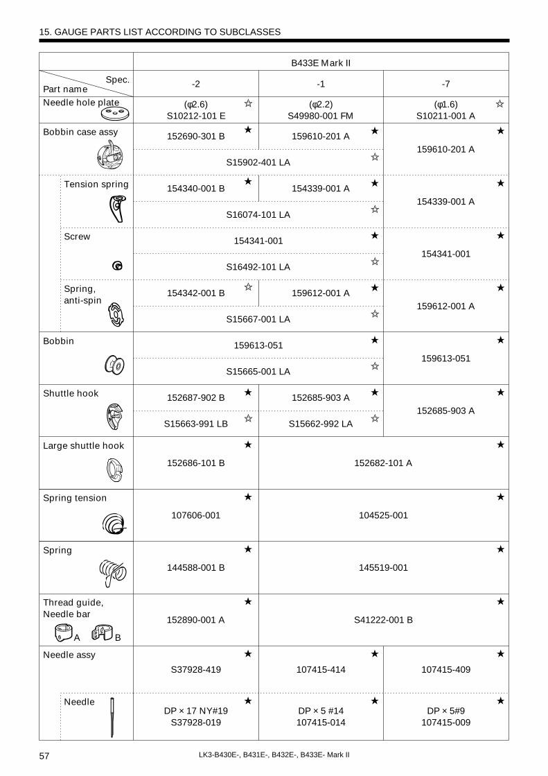
57 LK3-B430E-, B431E-, B432E-, B433E- Mark II
-1 -7Spec.
Tension spring
Screw
Spring, anti-spin
(φ1.6)S10211-001 A
159610-201 A
154339-001 A
154341-001
159612-001 A
Part nameNeedle hole plate
Bobbin case assy
B433E Mark II
-2
(φ2.2)S49980-001 FM
(φ2.6)S10212-101 E
159610-201 A152690-301 B
S15902-401 LA
154339-001 A
159612-001 A
152685-903 A
S15662-992 LA
154340-001 B
S16074-101 LA
154341-001
S16492-101 LA
154342-001 B
S15667-001 LA
�
★ ★
✩
★ ★
✩
★ ★
✩
★ ★
✩
Needle ★ ★DP × 5#9
107415-009
107415-414
DP × 5 #14107415-014
DP × 17 NY#19S37928-019
★
★
★ ★
107415-409S37928-419
Needle assy
Large shuttle hook
Spring tension
159613-051
152685-903 A
152682-101 A
104525-001
145519-001
S41222-001 B
Bobbin
Shuttle hook
159613-051
S15665-001 LA
152687-902 B
S15663-991 LB
152686-101 B
107606-001
★ ★
✩
★ ★
★
★
★
★
★
★
★
★
✩
★
✩
Spring
144588-001 B
Thread guide, Needle bar
152890-001 A
A B
✩✩
✩
★
★
15. GAUGE PARTS LIST ACCORDING TO SUBCLASSES
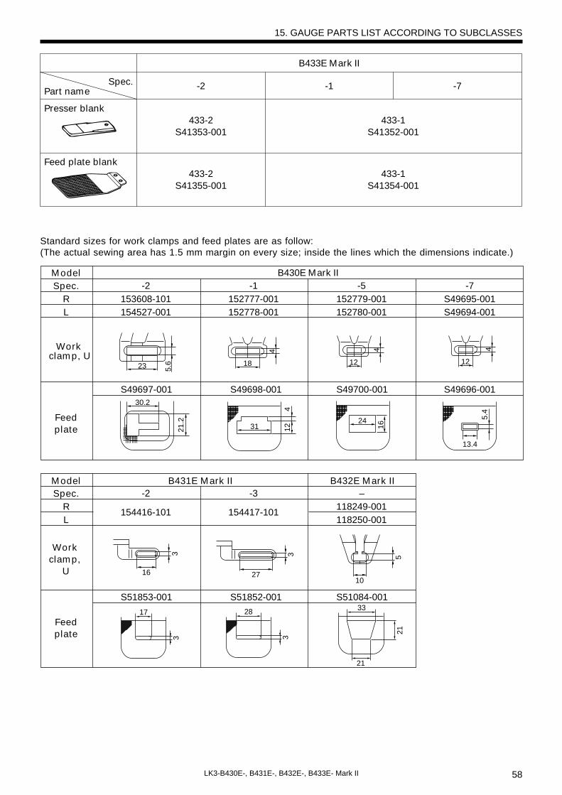
58LK3-B430E-, B431E-, B432E-, B433E- Mark II
15. GAUGE PARTS LIST ACCORDING TO SUBCLASSES
-3 –-2R
154417-101118249-001
154416-101118250-001
S51852-001 S51084-001S51853-001
L
Spec.Model B432E Mark IIB431E Mark II
Work clamp,
U
Feedplate
33
21
21
28
3
17
3
16
3
27
3
10
5
-1 -7Spec.Part name
Presser blank
Feed plate blank
B433E Mark II
-2
433-1S41352-001
433-1S41354-001
433-2S41353-001
433-2S41355-001
Standard sizes for work clamps and feed plates are as follow:(The actual sewing area has 1.5 mm margin on every size; inside the lines which the dimensions indicate.)
-1 -5-2 -7R 152777-001 152779-001153608-101 S49695-001
152778-001
18
3124
30.2
12 1621.2
4
4
12234
5.6
152780-001154527-001 S49694-001
S49698-001 S49700-001S49697-001 S49696-001
L
Spec.B430E Mark IIModel
Work clamp, U
Feedplate
12
4
13.4
5.4
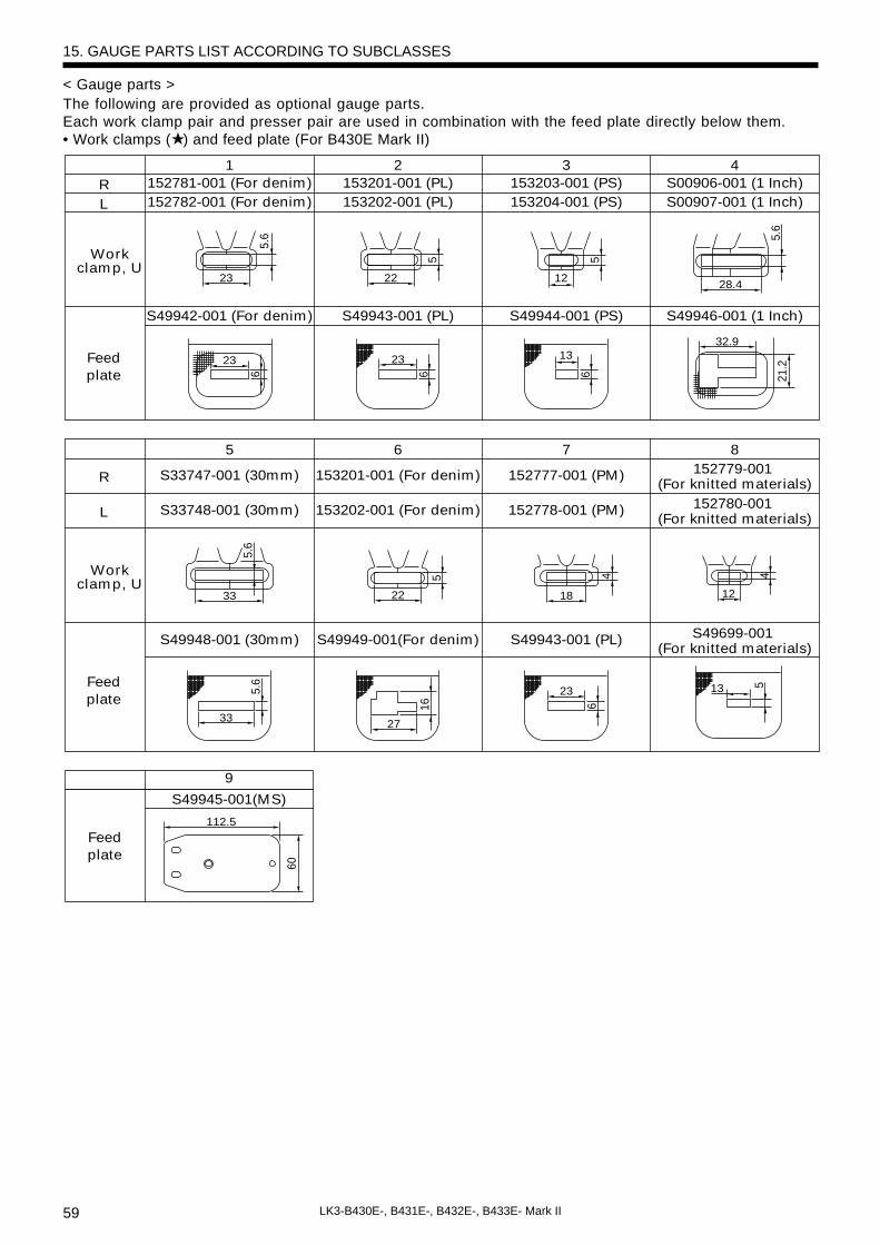
59 LK3-B430E-, B431E-, B432E-, B433E- Mark II
< Gauge parts >The following are provided as optional gauge parts.Each work clamp pair and presser pair are used in combination with the feed plate directly below them.• Work clamps (★ ) and feed plate (For B430E Mark II)
15. GAUGE PARTS LIST ACCORDING TO SUBCLASSES
1 2 3 4R 152781-001 (For denim)
152782-001 (For denim)153201-001 (PL)153202-001 (PL)
153203-001 (PS)153204-001 (PS)
S00906-001 (1 Inch)S00907-001 (1 Inch)
S49942-001 (For denim) S49943-001 (PL) S49944-001 (PS) S49946-001 (1 Inch)
L
Workclamp, U
Feedplate
Workclamp, U
Feedplate
5 6 7 8
R S33747-001 (30mm)
S33748-001 (30mm)
153201-001 (For denim)
153202-001 (For denim)
152777-001 (PM)
152778-001 (PM)
152779-001 (For knitted materials)
152780-001 (For knitted materials)
S49948-001 (30mm) S49949-001(For denim) S49943-001 (PL) S49699-001 (For knitted materials)
L
23
23
33
33 27
23
22 18
5.6
5.6
16 6
5 4
23 1332.9
6 6 6 21.2
22 12 28.4
5.6
5 5
5.6
13 5
12
4
S49945-001(MS)
Feedplate
9
112.5
60

60LK3-B430E-, B431E-, B432E-, B433E- Mark II
15. GAUGE PARTS LIST ACCORDING TO SUBCLASSES
11 12 13
S46771-001(For straight bar
tacking/submerged)
S46774-001(For vertical bar
tacking)
S46774-001 (For vertical bar
tacking/submerged)
S46770-001(For straight bar
tacking/submerged)
S46773-001(For vertical bar
tacking)
S46773-001(For vertical bar
tacking/submerged)
S49974-001 (For straight bar
tacking/submerged)
S49971-001 (For vertical bar
tacking)
S49975-001 (For vertical bar
tacking/submerged)
156006-001 156006-001 156006-001017680-512 017680-512 017680-512 017680-512
R
L
Work clamp, U
Feedplate
Work clamp, U
Bolt
10
S46771-001 (For straight bar
tacking)
S46770-001 (For straight bar
tacking)
S49970-001 (For straight bar
tacking)
156006-001
32.4
5.6
32.4
5.6
4.4
13
4.4
13
42
16.5
33
3
5
13
15
23
14.6φ13
14.6
10
10
15
RS46777-001
(For circular stitching)
S46780-001(For crescent bar
tacking)
LS46776-001
(For circular stitching)
S46779-001(For crescent bar
tacking)
Feedplate
Work clamp, U
Bolt
S49972-001(For circular stitching)
156006-001
S49973-001(For crescent bar
tacking)
156006-001
Work clamp, U
017680-512017680-512
14
φ13
* Separate programs must be created if using 14 or 15.
3834
20.4
42
with lozenge
Without lozenge
Feedplateblank
15994-000
S49976-000
S49977-000
S49978-000
Presser blank
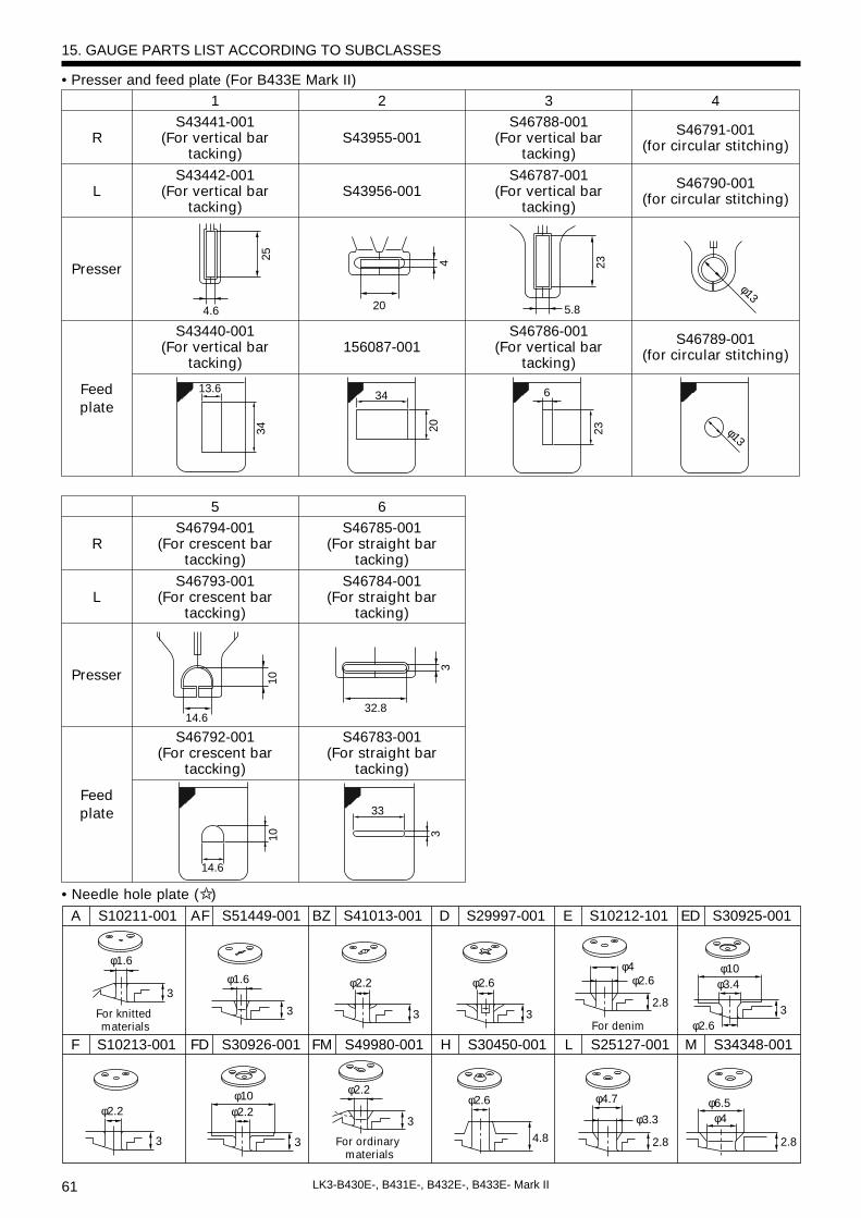
61 LK3-B430E-, B431E-, B432E-, B433E- Mark II
15. GAUGE PARTS LIST ACCORDING TO SUBCLASSES
S10211-001A S51449-001AF
For knitted materials
For ordinary materials
For denim
S30926-001FD
S41013-001BZ
S49980-001FM
S29997-001D
S30450-001H
S10212-101E
S25127-001L
S30925-001ED
S34348-001MS10213-001F
3
3
3 3
4.8 2.8 2.8
2.83
3
φ1.6
φ2.2
3
φ1.6
φ10
φ2.2 φ2.6
φ2.6 φ4.7 φ6.5φ4φ3.3
φ2.6φ10φ3.4
φ2.2
φ2.6
φ4
3
φ2.2
• Needle hole plate (✩ )
2 3 4
S43955-001S46788-001
(For vertical bar tacking)
S46791-001(for circular stitching)
S43956-001S46787-001
(For vertical bar tacking)
S46790-001(for circular stitching)
156087-001S46786-001
(For vertical bar tacking)
S46789-001(for circular stitching)
R
L
Presser
Feed plate
1S43441-001
(For vertical bar tacking)
S43442-001(For vertical bar
tacking)
S43440-001 (For vertical bar
tacking)
6S46785-001
(For straight bar tacking)
S46784-001(For straight bar
tacking)
S46783-001(For straight bar
tacking)
R
L
Presser
Feed plate
5S46794-001
(For crescent bar taccking)
S46793-001(For crescent bar
taccking)
S46792-001 (For crescent bar
taccking)
4.6
25
20
4
5.8
23
φ13
13.6
34
34
20
6
23 φ13
32.8
3
14.6
10
14.6
33
310
• Presser and feed plate (For B433E Mark II)
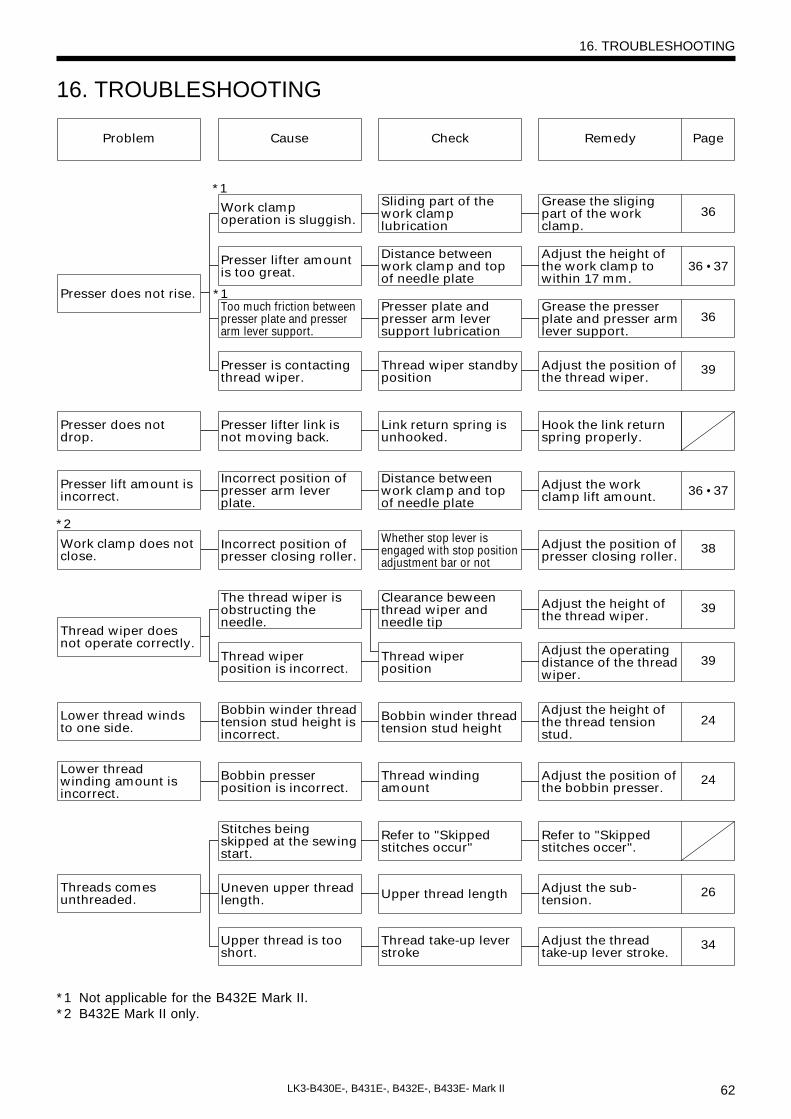
62LK3-B430E-, B431E-, B432E-, B433E- Mark II
16. TROUBLESHOOTING
16. TROUBLESHOOTING
Problem Cause Check Remedy Page
Presser does not rise.
Presser does not drop.
Presser lift amount is incorrect.
Work clamp operation is sluggish.
Sliding part of the work clamp lubrication
Grease the sliging part of the work clamp.
36
Presser lifter amount is too great.
Distance between work clamp and top of needle plate
Adjust the height of the work clamp to within 17 mm.
36 • 37
Too much friction between presser plate and presser arm lever support.
Presser plate and presser arm lever support lubrication
Grease the presser plate and presser arm lever support.
36
Presser is contacting thread wiper.
Thread wiper standby position
Adjust the position of the thread wiper.
39
Presser lifter link is not moving back.
Link return spring is unhooked.
Hook the link return spring properly.
Incorrect position of presser arm lever plate.
Distance between work clamp and top of needle plate
Adjust the work clamp lift amount. 36 • 37
Thread wiper does not operate correctly.
The thread wiper is obstructing the needle.
Clearance beween thread wiper and needle tip
Adjust the height of the thread wiper.
39
Thread wiper position is incorrect.
Thread wiper position
Adjust the operating distance of the thread wiper.
39
Lower thread winds to one side.
Bobbin winder thread tension stud height is incorrect.
Bobbin winder thread tension stud height
Adjust the height of the thread tension stud.
24
Lower thread winding amount is incorrect.
Bobbin presser position is incorrect.
Thread winding amount
Adjust the position of the bobbin presser.
24
Stitches being skipped at the sewing start.
Refer to "Skipped stitches occur"
Refer to "Skipped stitches occer".
Threads comes unthreaded.
Uneven upper thread length. Upper thread length Adjust the sub-
tension.26
Upper thread is too short.
Thread take-up lever stroke
Adjust the thread take-up lever stroke.
34
Work clamp does not close.
Incorrect position of presser closing roller.
Adjust the position of presser closing roller.
38
*1
*2
*1
Whether stop lever is engaged with stop position adjustment bar or not
* 1 Not applicable for the B432E Mark II.* 2 B432E Mark II only.

63 LK3-B430E-, B431E-, B432E-, B433E- Mark II
16. TROUBLESHOOTING
Problem Cause Check Remedy Page
Upper thread breaks.
Upper thread tension is too strong. Upper thread tension Adjust the upper
thread tension. 26
Lower thread breaks.
Skipped stitches occur.
Needle breaks.
Needle is installed incorrectly. Needle direction
Install the needle so that the groove is facing forward.
23
Thread is too thick for the needle. Thread and needle Use the correct
thread for the needle. 23
Thread take-up spring tension and height are incorrect.
Thread take-up spring tension and height
Adjust the tension and height of the thread take-up spring.
27
Damaged or burred rotary hook, needle hole plate or needle.
Damage or burringFile smooth or replace the afffected part.
Thread melting (synthetic thread) Thread edge Use a thread cooling
device (optional). 65
Lower thread tension is too strong. Lower thread tension Adjust the lower
thread tension. 26
Corners of needle hole plate or bobbin care are damaged.
DamageFile smooth or replace the affected part.
Clearance between needle and rotary hook tip is too great.
Needle clearance Adjust the needle clearance. 33
Incorrect needle and rotary hook timing.
Needle bar lift amount
Adjust the needle bar lift amount. 32
Driver is contacting needle more than is necessary.
Clearance between driver and needle
Adjust the driver needle guard. 33
Needle is bent. Bent needle Replace the needle.
Needle is installed incorrectly. Needle direction
Install the needle so that the groove is facing forward.
23
Needle clearance Adjust the needle clearance. 33
Needle is touching the rotary hook.
Needle bar lift amount.
Adjust the needle bar lift amount. 32
Needle is bent. Bent needle Replace the needle.
Needle is too thin. Needle and threadUse the correct needle for the material.

64LK3-B430E-, B431E-, B432E-, B433E- Mark II
Problem Cause Check Remedy Page
Upper thread is not trimmed.
Fixed knife is blunt. Fixed knife blade Sharpen or replace the fixed knife.
Thread jamming.
Poor seam finish on reverse side of material.
Incorrect thread tightness.
Shuttle race thread guide position
Adjust the position of the shuttle race thread guide.
33Movable knife does not pick up the thread. Needle bar lift
amountAdjust the needle bar lift amount. 32
The movable knife does not pick up the thread because of skipped stitches at the sewing end.
Skipped stitches at sewing end
Refer to "Skipped stitches occur".
Movable knife position is incorrect.
Movable knife position
Adjust the position of the movable knife. 34
Sub-tension is too weak. Sub-tension
Turn the sub-tension nut to adjust the tension.
26
Thread take-up spring tension and height are incorrect.
Thread take-up spring tension and height
Adjust the tension and height of the thread take-up spring.
27
Incorrect needle and rotary hook timing.
Needle bar lift amount
Adjust the needle bar lift amount. 32
Shuttle race thread guide is not separating the threads.
Shuttle race thread guide position
Adjust the position of the shuttle race thread guide.
33
Shuttle race thread guide is not separating the threads.
Shuttle race thread guide position
Adjust the position of the shuttle race thread guide.
33
Upper thread is not properly tight. Upper thread tension. Adjust the upper
thread tension. 26
Uneven upper thread length. Upper thread length Adjust the sub-
tension. 26
Upper thread is too long.
Thread take-up lever stroke
Adjust the thread take-up lever stroke. 34
Upper thread tension is too weak.
Lower thread tension is too weak.
Upper thread tension Adjust the upper thread tension. 26
Lower thread tension Adjust the lower thread tension. 26
Thread take-up spring tension and height are incorrect.
Thread take-up spring tension and height
Adjust the tension and height of the thread take-up spring.
27
16. TROUBLESHOOTING
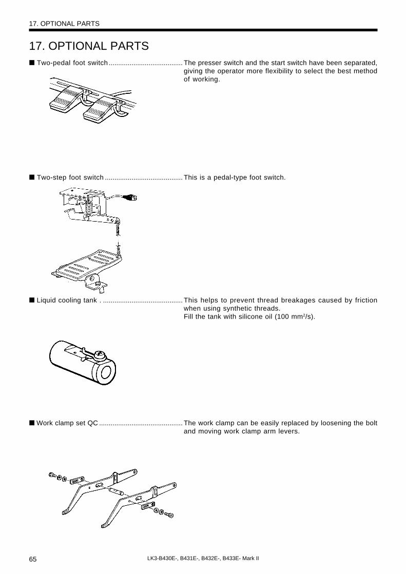
65 LK3-B430E-, B431E-, B432E-, B433E- Mark II
17. OPTIONAL PARTS■ Two-pedal foot switch ....................................... The presser switch and the start switch have been separated,
giving the operator more flexibility to select the best methodof working.
■ Two-step foot switch ......................................... This is a pedal-type foot switch.
■ Liquid cooling tank . .......................................... This helps to prevent thread breakages caused by frictionwhen using synthetic threads.Fill the tank with silicone oil (100 mm2/s).
■ Work clamp set QC ............................................ The work clamp can be easily replaced by loosening the boltand moving work clamp arm levers.
17. OPTIONAL PARTS
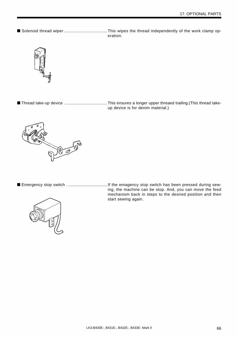
66LK3-B430E-, B431E-, B432E-, B433E- Mark II
■ Solenoid thread wiper ....................................... This wipes the thread independently of the work clamp op-eration.
■ Thread take-up device . ..................................... This ensures a longer upper threaed trailing.(This thread take-up device is for denim material.)
■ Emergency stop switch . ................................... If the emagency stop switch has been pressed during sew-ing, the machine can be stop. And, you can move the feedmechanism back in steps to the desired position and thenstart sewing again.
17. OPTIONAL PARTS

INSTRUCTION MANUAL
BROTHER INDUSTRIES,LTD. NAGOYA,JAPAN
Printed in Japan 118-V30, V31V32, V33
S91V30-102,-10+2000.03. B (1)