
LJNGLEYSUB-UBRARY - NASA of parallel wing a 75 inches-Chord of wing at 7 ft. from the center = 72...
32
LJNGLEYSUB-UBRARY - -rt - I H t. Aid TECHNICAL EEi1IOPANDLJMS NATICNAL ADVISORY COMMITTEE FOR AERONAUTICS No 214 THE "TURKEY UZARD" LIDR y Roy G. Mille' and E. T. Brom. (One . of Winners of 0-licler Uesicn Corimetition oonc'uced b '1i 2'h:' ) Taken from Y1igt A:i1 12, T9, 26, and !.ay 3, 1923 June, 1923 NACA L1BRAR' LA$L&V AJ1ONAUT1AL LAOL*ATOEY Le1 F%d. Vs. https://ntrs.nasa.gov/search.jsp?R=19930084584 2018-05-27T21:27:39+00:00Z
Transcript of LJNGLEYSUB-UBRARY - NASA of parallel wing a 75 inches-Chord of wing at 7 ft. from the center = 72...

LJNGLEYSUB-UBRARY- -rt - I
H t. Aid
TECHNICAL EEi1IOPANDLJMS
NATICNAL ADVISORY COMMITTEE FOR AERONAUTICS
No 214
THE "TURKEY UZARD" LIDR
y Roy G. Mille' and E. T. Brom.
(One . of Winners of 0-licler Uesicn Corimetition oonc'uced b '1i 2'h:' )
Taken from Y1igt A:i1 12, T9, 26,
and !.ay 3, 1923
June, 1923
NACA L1BRAR' LA$L&V AJ1ONAUT1AL LAOL*ATOEY
Le1 F%d. Vs.
https://ntrs.nasa.gov/search.jsp?R=19930084584 2018-05-27T21:27:39+00:00Z

LI
NATIONAL ADVISORY COMMITTEE FOR AERONAUTICS..
TECHNICAL MEMORANDUM NO.2I
THE "TURKEY BUZZARD' GLIDER.*
By Roy G. Miller and D. T. Brown.
(One of winners of Glider Design Competition conducted by "Flight.")
General Description.
The "Turkey Buzzard is a semi-internally braced monoplane
(Fig. 1). The wing is placed above the fuselage for two important
aerodynamical reasons: first, because this position minimizes the
mutual interference between the wing and the fuselage, and, sec-
ond, useful lifting surface is utilized with the wing passing over
the fuselage instead of through it. Structural simplicity is main-
tained by not breaking the fuselage fairing and the wing profile.
The short lift-struts greatly reduce the weight of the wing beams,
and do not offer much head resistance.
The plan form of the wing is tapered to improve the aerodynam-
ical efficiency and to reduce the structural weight. The profile
is tapered solely for aerodynamical reasons.
The ribs employed are of stiff paDer, reinforced with wood cap-
strips and stiffeners which are cemented on by means of dope. This
type of rib is extremely light and strong. An experimental rib of
six-foot chord weighed only 0.22 lb and stood a test load- of 264 lbs
before breaking. This corresponds to a load factor of about 25g
* Taken from "Flight," April 12, 19, 26, and May 3, 1923.
-2-
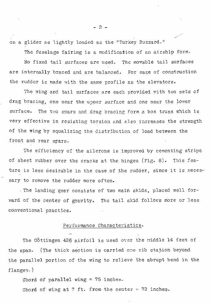
on a glider as lightly loaded as the !Turkey Buzzard.
The fuselage fairing is a modification of an airship form.
No fixed tail surfaces are used. The movable tail surfaces
are internally braced and are balanced. For ease of construction
the rudder is made with the same profile as the elevators.
The wing and tail surfaces are each provided with two sets of
drag bracing, one near the upper surface and one near the lower
surface. The two spars and drag bracing form a box truss which is
very effective in resisting torsion and also increases the strength
of the wing by equalizing the distribution of load between the
front and rear spars.
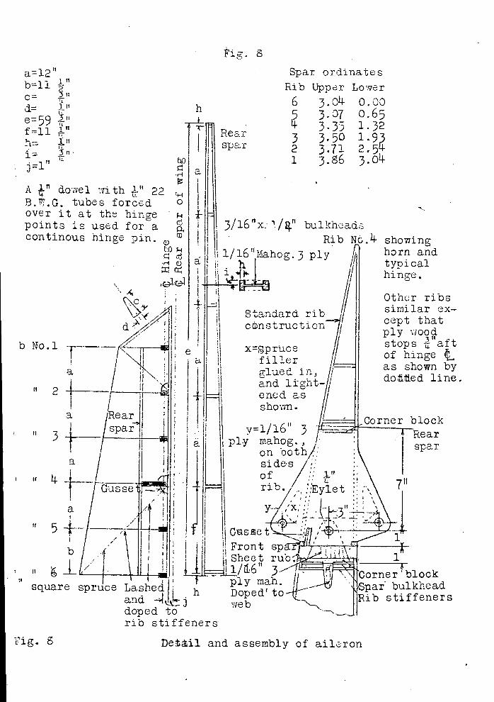
The efficiency of the ailerons is improved by cementing strips
of sheet rubber over the cracks at the hinges (Fig. 8). This fea-
ture is less desirable in the case of the rudder, since it is neces-
sary to remove the rudder more often.
The landing gear consists of two main skids, placed well for-
ward of the center of gravity. The tail skid follOws more or less
conventional practice.
Performance Characteristics.
The Gattingen 426 airfoil is used over the middle 14 feet of
the span. (The thick section is carried one rib station beyond
the parallel portion of the wing to relieve the abrupt bend in the
flanges.)
Chord of parallel wing a 75 inches-
Chord of wing at 7 ft. from the center = 72 inches.
- 3 -
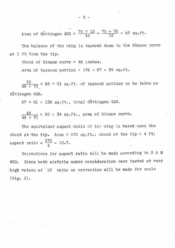
Area of Göttingen 426 = 75 X 12 12 +75 12
= 87 sq.-Lo-U--
The balance of the wing is tapered down to the Sloane curve
at 1 ft from the tip.
Chord of Sloane curve = 48 inches.
Area of tapered portion = 172 - 87 = 85 sq.ft.
72 85 = 51 sq.ft. of tapered portion to be taken as 48 ± 72
Gottingen 426.
87 + 51 138 sq.f't., total Gttingen 426.
48 x 85 34 sq.ft., area of Sloane curve. 48 + 72
The equivalent aspect ratio of the wing is based upon the
chord at the tip. Area = 172 sq.ft.; chord at the tip 4 ft;
aspect ratio = 172 = 10.7. 4.
Corrections for aspect ratio will be made according to R & M
450. Since both airfoils under consideration were tested at very
high values of LV ratio no correction will be made for scale
(Fig. 2).
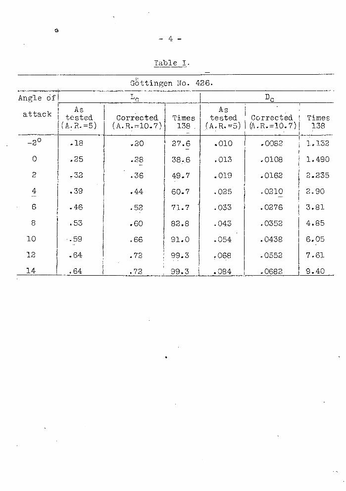
Table I
I'll No. 426.
Angle 6t Lc Dc __________________________
As As I
attack tested Corrcted i Times tested I Corrected Times l(A . R.= 5) (A.R.10.7) 138 ( 138
-2 0 11 .18 .20 1 27,5 .010 .0082 1.132
0 .25 .28 38.. 6 .013 .0108 1.490
2 .32 .36 49.7 .019 .0162 2.235
.44 60.7 .025 .0210 2.90
6 .46 I .52 71.7 .033 .0276 3.81
8 .53 .60 82.8 .043 .0352 4.85
10 .59 .66 91.0 .054 .0438 6.05
12 .64 .72 99.3 .068 .0552 7.61
14[ .64 1 .72 _ 99.3 _.084 .0682j 9.40
-5-
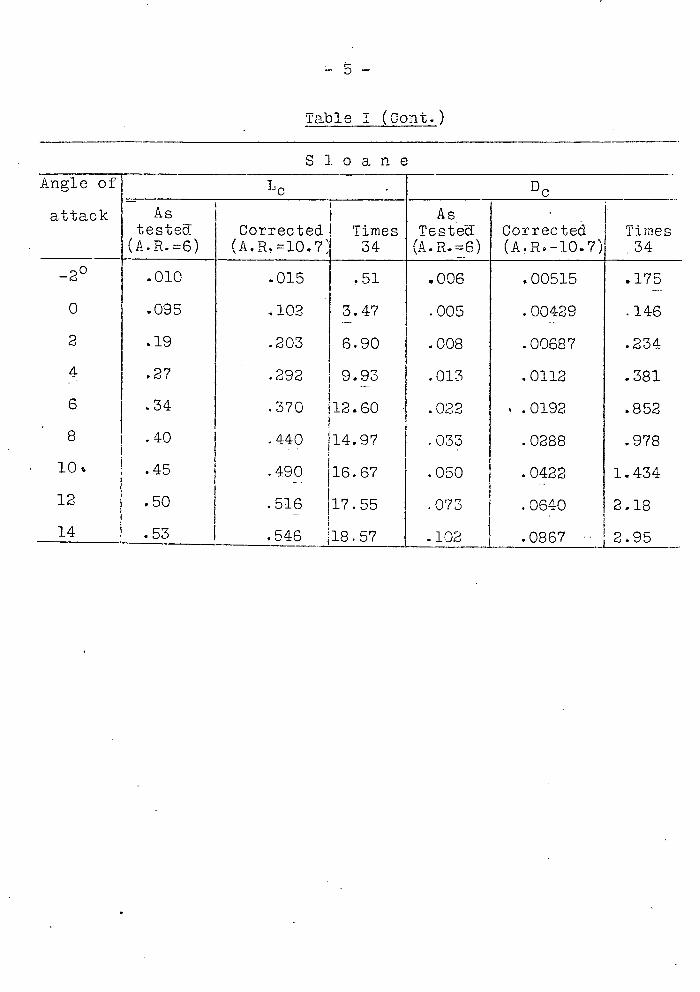
Table I (Cont.)
S 1 0 a n e Angle of Lc . Dc attack AS As
tested- Corrected Times Tested Corrected Times (A.R.=6) (A.R.=10.7 34 (A.PL.=6) (A.R-10.7) 1 34
-20 .010 .015 .51 .006 .00515 .175
0 .095 102 3.47 .005 .00429 .146
2 .19 .203 6.90 .008 .00687 .234
4 .27 .292 9.93 .013 .0112 .381
6 .34 .370 112.60 .022 . .0192 .852
8 1 .40 .440 1 14.97 .033 .0288 .978
10 •45 .490 16.67 .050 .0422 1.434
12 .50 .516 17.55 .073 .0640 218
14 .53 1.546 18.57 .102 j .0867
-6--
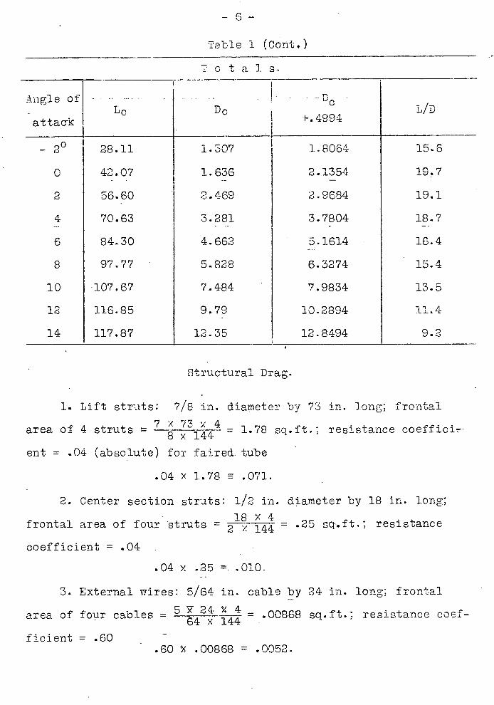
Table 1 (Cont)
C t a 1 S.
_'k-ngle of
attack I Lc D c LID
- 20 28.11 1.507 1 1.8064 156
0 42.07 1.633 2.1354 19.7
2 56.60 2.469 2.9684 1911
4 70.63 3.281 3.7804 18.7
6 84.30 4.662 5.1614 16.4
8 97.77 5.828 6.3274 15.4
10 107.67 7.484 7.9834 13.5
12 116.85 9.79 10.2894 11.4
14 117.87 12.35 12.8494 9.2
Structural Drag.
1. Lift struts: 7/8 in. diameter by 73 in. long; frontal g
area of 4 strutsx x 4 = 1.78 so.ft.: resistance coefficir. 8 144
ent = ..04 (absolute) for faired. tube
.04 X 1.78 .071.
2. Center section struts: 1/2 in. diameter by 18 in. long;
frontal area of four truts = 2x 14 = .25 sqft.; resistance
coefficient .04
.04 y .25
3. External wires: 5/64
area of four cables =64 Y
ficient .60 - .60 ') .00
.010.
in. cable by 24 in. long; frontal
144.00868 sq.ft.; resistance coef-
368 .0052.
-7- /
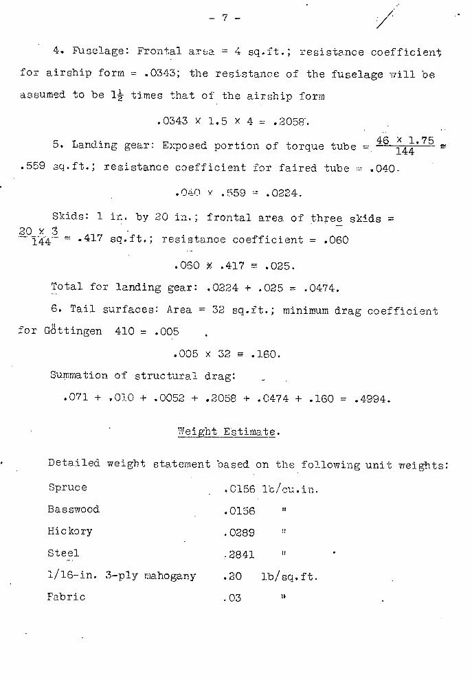
4. Fuselage: Frontal a:rsa 4 sq.ft.; resistance coefficient
for airship form = .0343; the resistance of the fuselage -..,iill be
assumed to be l times that of the airship form
.0343 Y 1.5 x 4 = .2058.
5. Landing gear: Exposed portion of torque tube = 46 X 1.75
.559 sq.ft.; resistance coefficient for faired tube .040.
.040 y •59 = .0224.
Skids: 1 in. by 20 in.; frontal area of three skids 20
.417 sq.ft.; resistance coefficient .060
.060 X .417 .025.
Total for landing gear: .0224 + .025 = .0474.
6. Tail surfaces: Area = 32 sq.ft.; minimum drag coefficient
for Gittingen 410 .005
.005 x 32 0 .160.
Summation of structural drag:
.071 + .010 + .0052 + .2058 + .0474 + .160 = .4994.
Weight Estimate.
Detailed weight statement based on the following unit weights:
Spruce .0156 lb/cu.in.
Basswood .0156 u
Hickory .0289
Steel .2841
1'16-in. 3-ply mahogany .20 lb/sq.ft.
Fabric .03
- 8 -
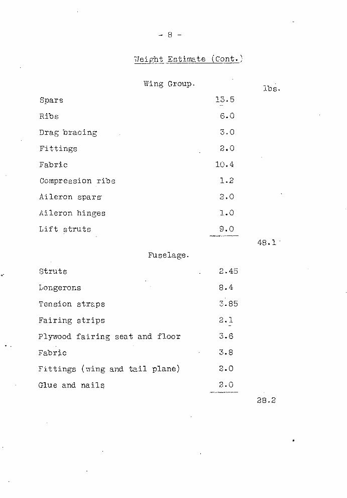
WeiRht Estirriate (Cont.'
Wing Group.
Spars 13.5
Ribs 6.0
Drag bracing 3.0
Fittings 2.0
Fabric 10.4
Compression ribs 1.2
Aileron spars 2.0
Aileron hinges 1.0
Lift struts 9.0
lbs.
48.1
Fuselage.
Struts 2.45
Longerons 8.4
Tension straps 3.85
Fairing strips 2.1
Plywood fairing seat and floor 3.6
Fabric 3.8
Fittings (wing and tail plane) 2.0
Glue and nails 2.0
28.2

-9-
Weight Estimate (Cont.)
Ribs
Spars
Special rib
Fabric
Glue and nails
Horizontal Tail Surfaces.
1.56
3.50
32
1.32
7
7.00
Rudder: Weight is proportional to area of horizontal surface 3.2
Landing Gear.
Torque tube 6.0
Skids (three) 6.8
Horns, fittings and cord 2.0
14.8
Controls.
Stick .55
Pulleys .83
1.38
Total dead weight 102.7 lbs.
The stress analysis nas based on
mate of 150 lbs., which was purposely
an ample factor of safety. Using the
above and the live load of 150 lbs. k
load factor will be 4.8 instead of 4,
will be 3.7 instead of 3.08 (Fig. 3).
an original dead weight esti-
made high in order to ensure
dead weight as calculated
pt the same, the low speed
and in the diving condition
-' (' - -
Fuselage
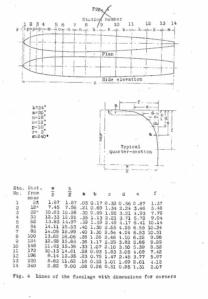
The fuselage is a modification of an airship form with cor-
iers rounded, as shown in Fig. 4, to conforrti to sine curve.
The cross-sectional area at each station is proportional to
the cross-sectional area of an airship hull but the shape of the
cross-section is modified to suit structural considerations as
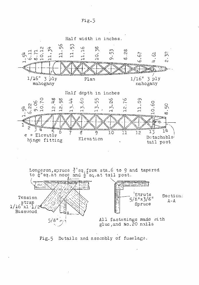
shown in Figs. 5 and. 6.
Wing Ribs.
Drawing (Fig. 7) shows a typical rib, with the dimensions of
the various ribs indicated in tabular form. it
Gottingen No. 426 section. The flanges, or
Spruce, and are doped to the cartridge pape
ers are placed vertically between upper and
ble intervals, and always against front and
spars where these intersect the ribs.
Rib No.10 is the
'cap strips' are of
r web. Spruce stiffen-
lower flanges at suita-
rear faces of the wing
In the case of the compression ribs a further strengthening
is provided by horizontal fore-and-aft compression members of
Spruce, running outside the vertical stiffeners, and lashed to them.
Wing Spars.
Another set of drawings shows the general lay-out of the wing,
and gives details of the wing spars (Figs. 9 and 10).
The dimensions of the tapering portion of the spar are given
in the small table at the top of Fig. 9.
- U -
The trailing edge is formed by braided cord of 'fish-line.
The internal drag bracing is piano wire.
Fittings.
The wing design calls for practicall y no metal fittings. The
few fittings required for the internal drag bracing are of the sim-
plest form, i.e., plain strips of sheet steel of light gage, passed
through slots in the spar webs and having their ends splayed out , Fig. 11
at the required angle. One such fitting is shown in/dealing with
the fitting for the "A 1' struts which secures the center section of
the wing to the fuselage.
On another drawing (Fig. 15) is shown one of the very simple
fittings by means of which the lift struts are attached to the
wing spars.
Ailerons.
The ailerons (Fig. 8) are of a construction similar to that
of the wings. The ribs are similar to the main ribs, except for
No. 4, shown in the drawing, which carries the ailerons horn.
This rib is made up of two pieces of mahogany, placed one on each
side of the rib, and having between them a spruce filler glued in
and lightened as shown by dotted line. The hinges are formed of
three-ply plates, of spade shape as indicated in the drawings, with
a continuous hinge pin formed of a 1/4-inch wood dowel rod, over
which is forced a length of 1/4-inch tube to form a bearing surface
at the hinge points. Similarly a metal bush in the form of an eye--
let is formed on the three-ply plates providing the hinges.
- 12 -
Elevator.
In general design the elevator is of similar construction to
that of the wing (Figs. 12 and 13). The ribs are similar to the
wing ribs in construction, with the exception of the center rio
T has a three-ply web in place of the thick paper webs. The
section used is Gttingen No. 410, and the dimensions of the vari-
ous ribs are given in the accompanying table. It should be pointed
out that the section is a symmetrical one, i.e., biconvex, and that
the dimensions given in the table are half-depths.
The elevator crank lever or "horn" is in the form of two plates
placed one on each side of the central rib (Detail A, Fig. 13), and
attached at corner blocks and packing pieces by small bolts. The
elevators are mounted on the sides of the fuselage, as indicated in
the side view (Figs. 1, 5 and 14). The corresponding bearings on
the front spar of the elevator are shown in the elevator, (Detail
B, Fig. 13). The stern post of the fuselage is detachable, so as
to admit of the elevator being put into place (Fig. 5).
Piir cr -
No construction drawing is provided for the rudder, since the
construction is so nearly like that of the elevators. Spars sirnila1
to those in the elevatoiare used. The lower ends are drawn down
to fair-in with the fuselage. Ribs 2 to 6 inclusive of the eleva-
tor are duplicated on the rudder. Ribs q and 3 have the noses cut
off. The horns are similar to those used for the elevators, and ar
attached to rib Io. 3. All the ribs are 0± a construction similar
to those employed in the wing.
Landing Gear.
The landing gear consists of to skids placed well forward of
the center of gravity, (Figs. 16 and 17). They are mounted on the
ends of a torque tube, which transmits the rotational deflections
to a shock absorber located within the fuselage. This tube Is of
steel and runs across the bottom of the fuselage, through bearings
on the lower longerons. This arrangement permits quite a wide
track for the landing skids.
Tail Skid.
The tail skid is of hickor y, and is of the usual swivelling
type (Fig. 14). The fitting is attached centrally to a cross-beam
or strut of the fuselage, The arrangement of swivel fitting, rub-
ber shock absorbers and "snubber" should be clear from the drawing.
The control stick is tubular in form (Fig. 15), and the foot
bar of the usual type.
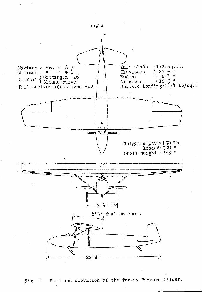
Fig.l
/
Maximum chord Minimum If LtJII
fS!oaneGottingen I426
Airfoil curve Tail sectionsGottingen .#lO
Main plane 172sq.ft. Elevators 22.14.
Rudder 8.7 U
Ailerons "
Surface loading l 7 11- lb/sq.
Weight empty 150 lb. loaded 300
Gross weight 253
32'
_5 1 6 U ---
6'3" Maximum chord
22'
Fig. 1 Plan and elevation of the Turkey Buzzard Glider.

10 See Table I for individual characteristics of the Gottingen 426
6 and. the Sloane airfoils.
4
Hi .Li±tttLrf t 5. Gross weight.
\
r
H L bD
.3W. 50
bD
3. C)
2 20
25 30 35 40 45
Airspeed, H.P.H.
Fig.2
2
0 0 -2 00 h0 • o 12° i6
Angie of attack
L/D -c 28 140
24 120
20 100
16 80
12 60
8 4o
20
0
I-
7: zi
D. '4
12
Fig.2 Aerodynamic characteristics and gliding angles of the "Turkey Buzzard Glider".
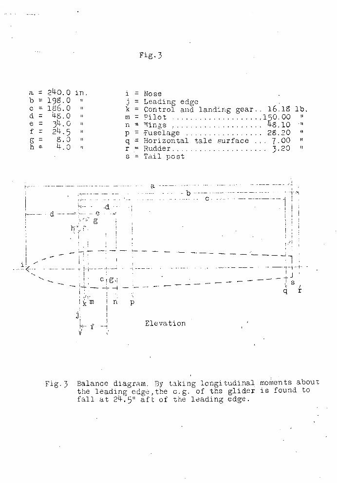
Fig.3
a 240.0 in. I = Nose b 19.0 1 = Leading edge c = 1E6.0 k Control and landing gear. . 16.1 lb. d = 48.0 in Pilot .................... 150.00
34.0 n . ..... . ..................... 48.10 TI
f 24.5 iip fuselage ................. 28.20
g = 8.0 q Horizontal tale surface . . . 7.00 h 43 r = Rudder ..................... 320
s = Tail post
a
...............................c.—...---------.----
-i.' d ....
g
h, I
- I
......-.--.i_-,_-_.
q r
n p
Elevation
Fig. 3 Balance diagram. By taking longitudinal, moments about the leading edge,the c.g. of the glider is found. to fall at 24.5" aft of the leading edge.
Statio/nu ber 1 2 3 4 5 6 7 8 /9 10 11 12 13 14
r k k----
T_riH1Side elevation
S
-:----.f--- n
EF=2 40
I
Typical 'quartersection
Sta. Dist w h No. from a b c d. e f
nose 1 2 S 1.87 1.87 .05 Q.17 0.33 0.56 0.8? 1.37 2 12 7.45 7.56 .21 0.69 1,34 2.24 3.46 5.46 3 22' 10.63 10.98 .30 0.99 1.92 3.21 4,93 7.79 4 32 12.33 12.91 .35 1.13 2.21 3.71 5.72 9.04 5 52 13.83 14.97 .39 1.29 2.49 4.17 6.41 10.14 6 64 14.11 15.53 .40 1.30 2.55 4.25 6.55 10.34 7 82 1.08 15.99 .40 1.30 2.54 4.24 6.53 10.31 8 100 13.62 16.06 .38 1.26 2.46 4.10 6.32 9.98 9 124 12.68 15.85 .36 1.17 2.29 3.82 5.88 9.29
10 148 11-63 15-36 .33 1.07 2.10 3.50 5.39 8.52 fl 172 10.13 14.61 .28 0.93 1.83 3.05 4.69 7.42 12 196 8.14 13.36 .23 0.75 1.47 2.45 3.77 5.97 13 220 5.62 11.62 .16 0,52 1.01 1.69 2.61 4.12 14 240 2.82 9.00 .08 0.26 0.51 0,85 1.31 2.07
Fig. 4 Lines of the fuselage with dimensions for corners
0 '-O N-
CUO Cu -0
IX\ •0\H
tOJ
ru oJ
7p1c
ON
to 0
• '.0 H H 0
H
.z- 0 : '.D LC\ CU
V. N\ v", 0 Lc\
to
Fig. 3
Half width in inches.
cu LC Lf\ '.0 tO H H H r\ - H tO
.zt r1 N- • H H • If', ('Si N- r4 ('I 0 H H H H 0 • '.0 '.0 V"
• '.0OH H H H 0\ tO
1/16" 3 ply Plan 1/16" 3 ply mahogany mahogany
Half depth in inches
• 50 9 10 11 12 1, lfr e = Elevaror Detachable; hinge fitting Elevation tail -00st
Loneron,sruce --'s q .from sta.6 to 9 and tapered to "sq.at nose and --"sq.at tail post.
Tension
U Section.-
trap Spruce
Basswood 'A_VAll fastenings made. ilith
S gluc,and No.20 nails
Fig-5 Details and assembly of fuselage.
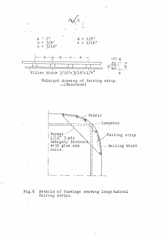
a 2" -. ci b 3/8" e
C = 3/1611
a.
t ifli FrT
Filler block 3/16"< 3./16'x i/"
Enlarged drawing -.-
of fairing strip. (Bass'7ood)
Longe ron
Former-1
mahogaiy fastene' with glue and nails.
-Fairing strip
Nailing block
Fig.6 Details of fuselage showing longitudinal fairing strips.

A
I^b
iiTTTTa=Lasdtostiffeners square spruce
stiffeners Table II
Dimensions given are in inches Dist. Up- Lov- Dist. Up Low- fr om per er fro m per er
sq. long- L.E. ord. ord. L.E. ord. ord.
udinals run Rib No.1 Rib No.2 ll length of
Ln0.00 0. .34 0.00 0.52 .52 0.60 O. .i 06L1 1.20 .20
Spruce 1.20 1.22 .05 1.28 1.60 09 2.40 1.6 .00 2.55 2.13 .01 3.60 1.92 o4 3.83 2J6 .02
De tail of nose 4L80 2.11 07 5.10 2.72 .05 7.20 2.35 .19 7.66 3.06 .10 0 .60 2.52 .22 10.20 3.32 .16
2 . 7 0 .30 15.30 3 . 5 .20 19.20 2.70 .27 20J-0 354 20 24L00 2.53 .23 25.50 3.27 .18 28.80 2.30 .19 30.60 289 .14 33.60 L98 .17 35.70 2.39 .13 3J40 1.57 ..10 14. 0.80 1.81 .10 3.20 1.02 .07 45.90 1.09 .03
1 -Paper doped 1+5.6o 6.65 .oi- 4 J-o 0.63 .00, to bulkhead 8.00• 0.10 .10 51.00 0.10 .10
Rib No-3 Rib No.4 000 0.70 70 0.00 0.9^ .92 0.68 1.50 .214. 0.71 1.85 .33 1.35 1.96 .11 lJ3 2.37 .19 2 . 7 0 2.57 .03 2.85 3.08 .06 405 3.00 .00 4.28 3 . 57 .045.40 3.31 .00 5.70 3.97 .02
Split cp strips8.11 .77 .05 8.55 .514- .01
10.80 10 .06 11.40 4.93 .00 square. 16.20 4.40 .10 17.10 5.28 .03 square corn- 21.60 4.36 .11 22.80
_ 18 .05
pression members 27.00 3 . 97 .14 28.50. .73 .12 fLon ribs 1)6,lO,32JI-0 3J-7 .15 3-L20 4.10 .17 f; 90 Armorplate 37.80 2.814- .17
.i1I39.90 3. 29
2.14-0.20
paper 43.20 2.11 45.60 .19 1Krat48.60 1.20 .08 51.30 1.35 .11 51.30 071 .02 5410 0.77 04
A-A 54.00 0.10 .10 57.00 0.10 .10 Table continued on next page
Figs 7 Detail and assembly of typical rib with table of ordinates for all ribs.

Fig.7 Qontinued Table II
(Continued Dimensions given are in indhes
Dist. Up- Lovr- Dist. Up- Lo-:r4- Dist. Up- Lo'-from per er from per er from per er L.E. ord. ord. L.E. ord. ord. L.E. ord. ord.
Rib No.5 Rib No.G Rib NO-7
0.00 1.20 1.20 0.00 1.47 1J7 0.00 1.60 1.80
0.75 2.29 .52 0.79 2.70 .68 0.83 3.15 .90 1.50 2.85 .3 6 1.58 3.33 . 1.65 3. .67
3.00 3.67 .18 3.15 4.22 .28 3.30 4L81 .
.50 4.22 .11 .72 68 .20 L95 5 . 5 .32
6.00 4L67 .08 6.30 5 . 37 ,15 6.60 6.10 .23
9.00 5.3)4 .05 9.)45 6.16 .08 9.90 7.00 .12 12.00 5.80 .00i2.60 6.7 0 .03 13.20 7.60 .03 16.00 6.23 .0018.90 7.16 .00 19.80 8.12 .00 24.00 6 0 .05 25.20 6.99 .07
j 26.40 7.88 .07
30.00 5.50 .12 31.60 6.29 .14 33.00 7.09 .16 36.00 .7)4 .20 37.80 .36 .26 39.60 6.06 .33 2.00 3.76 .26 )4 4,20 .29 . 33 6.20 )4.7$ .)40
48-.00 2.70 .25 50.40 3.04 . 35 52.50 3.34 .42 54 d 00 1.47 .13 56.7 0 1 .66 .21 I 59.40 1.78 .27
57.00 0.60 .0 59.80 0.92 .10 62.70 0.97 .11 60.00 0.10 .10 63.00 0.10 .10 166.00 0.10 .10
Rib No.8 Rib No.9 Rib No.10
0.00 2.13 2.1 0.00 2.45 2.45 0.00 2.53 2.53
0.s6 3.63 1.10 0.90 4.06 1.30 0.9)4 )4.26 1.37 1.73 .37 . .s4 i.o LL6 1.00 1.6 5.09. 1.11
3)45 5.)42 .60 3.60 6.01 . 73 3.75 6.2783
5.17 6.22 ,L5 .4o 6.90.50 5.62 7.17 .60
6.90 6.66 .36 7.20 7.60 .47; 7.50 7.89 .46 10.34 7.64 .18 10.80 8.66 .25 1 1L25 8.64 .43 13.80 8.52 .08 14J40 9J42 . 10: 15.00 9.83 .16 20.70 9.08 .00 21.60 10.05 .00 22.50 10.49 .00, 27.6 0 8.61 .09 26.60 9.72 .io: 30.00 10.14 .10 3)4.50 7 . 93 .21 36.00 8.70 .23 37.50 9.08 .23
14140 6.73 .140 3.20 7.36 .145 145.00 ^ .ot.66 •1#
48.30 5.28 .148 50.40 5.80 .56 52.50 .60 55.20 3.70 .50 57.60 14.03 .59 60.00 4.20 .62 62.10 1.94 .32 6)4.60 2.10 .39 67.50 2.19 .4]. 65.50 1.07 .15 66,40 1.13 .20 71.2.5 1.20 .19 69.00 0.10 .10 72.00 0.10 .10 75.00 0.10 1P
U 3
if
If 5
IT
square sp I,
11 ply j on both sides
rib Eylet
Y--
i f Gusse
spar
Front sp________1
I
Sheet rub,. 1/6" 3
e Lashedply mah.
and - L. h DopedT to-i
dopedweb
rib stiffeners
\.U'Corner block -- 4}Spar bulkhead
HRib stiffeners
'i.
Spar ordinates Rib Upper Lower
6 3.0 0.00 h
5 3.37 0.65 ' 3 . 35 1.32 Rear 3 3.50 1.9
spar 2 3.71 25 1 3 30L.
3/16x: '/ bu1khcad Rib N6.4 showing
H i1/lEUMahog.3 ply fl horn and a11 h typical hinges
a12' b11 -" C=
1= if U-
e59 '3.."
f=ll A n
-i= ill
I-bO
j=1"
A dowel with ." 22 ,U.
B..G. tubes forced over it at the hinge points is used for a a continous hinge pin.
ri )
3II1
Othcr ribs similar ex-cept that ply wood stops aft of hinge as shown by doed line.
1 Standard rib cnstruction
b No.1 T, xpruce
/ N a filler a I 1N ii 1ued in.
/__ HI and light-ened as
I shown. .ear IL
Fig. 9 Detail and assembly of ai1ron

Fig.. 9Rib Fr4 sta. Upper
5 75.9
6 8,16
7 530
S 5.42
9 S.52
10 .60
Dnt T Lower 350 2.51 2.04 1.23 0J2 0.00
Rear Upper Lower
7.55 3.49 755 2.51 7.55 2.05 7 . 55 1.29 7.55 o.46 7.55 0.00
1/16"3 ply mahog. h/4h
C
Flanges taper ifor-J ly from ribs 1 to 10
to sections as shown. Spar sections unifoDrn j from rib 11 to 1
Basswood bulkheads wide and and brought flush with beam flange. j
CL
a=12" f=5/16' n' b15- g--, 41 F.S. c= 6" d1/2" h=1/4' a e=3/S i=8.61.sb
j 7 . 55R ...s. èL
4-In
,Spruce H a
filler block, a see detail L____
I
I. drawing
1 1 1 .-Fig. 15
1/16 3 ply mahog
d e-J
f- 1-
Rear spar
0
Front spar
N.b 1
3 IT If 'Ii.
II Ii 5 II TI 6
II II 7
II IT5
II II9
10
n 'I 11
12
tI 13
ii
IT II 15
Fig. 9
I I L
Detail and assembly of wing spars.
Rib FrontFront sta. Upper Lower Tip 6.73 6.61
1 7.37 5.96 2 7.60 5.46 3 773 LL6 4 7.91 4.24
R Upper 6.56 7455 7.55 7.55
Lo.7er 6.7 6.06 5.
4,23

Fig. 10
Ribs Nos;. 1,, .6, 10 drag struts (compression ribs)
r spar---\
uare sprucefastened / \ to rib _- ---stiffeners
/-H 7\ •1
.-.
Rib No. 1
2
II IT 3
II .11
•
H II 5
- • . .:\ II II 6
•
IT Ii 7
TI If
• IT-
II
------Antidrag wire
Stiff paper :i nose doped. o
iL Drag wire
TI
Rea
1!! U.
Braided - cord
TraJ ing.-.. edge
•1 Fig. 10 Assembly of wing
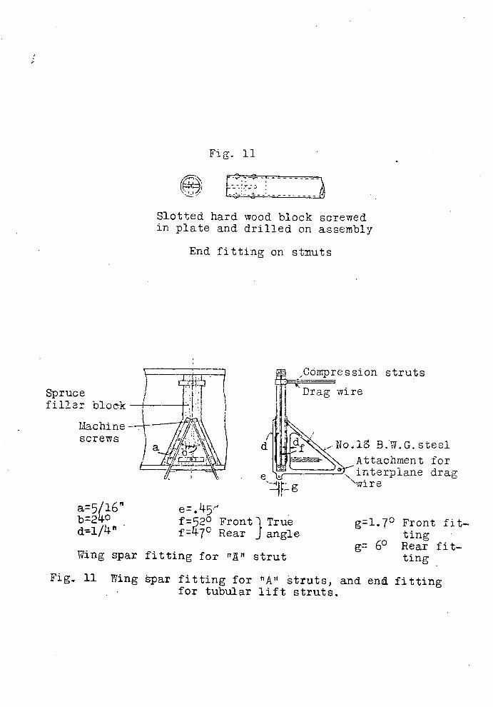
Cóipression struts Drag wire
-No.l B.W.G. steel Attachment for
_1! interplane drag "wire
Spruce filler bloc-k
Machine screws
e
Fig. 11
Slotted hard wood block screwed in plate and drilled on assembly
End fitting on stnuts
k
a5/l6" b=24°
e.5' f=2° Front I True f7° Rear J angle
Wing spar fitting for "A" strut
91.70 Front fit-ting
g 60 Rear fit-ting
Fig. 11 Wing spar fitting for "A" struts, and end fitting for tubular lift struts.

Rib N.6
If II 5 Braided
if 4
II U 1
U H 2
If U 3
'-Il
a= 3. b1/16"x3/4' basswood c1/16 3 x1/2 basswood d1/16x3/4' basswood e1/16 3 ply mahogany
Distance in inches from Ifrom L.E. Rib No.4 0.00 0.00 0.39 0.81' 0.78 1.13 1.56 1.54 2.34 1.53 3.12 2.04 4.6s 2.50 6.24 2.6 9.36 2.51
12.48 2.34 15.60 2.00 18.72 1.64 21,54 1.18 24.96 0.74 25.05 0.34 29.64 0.18 31.10 007 31.20 0.00 Rib No.6 0.00 0,30 0.60 1.20 1.80 2.40 3.60
7.20 9.60
12.00 14.4o 16.50 19.20 21.60 22.80 23.90 24.00 is at
0.00 0.32 0.44 0.60 0471 0.50 0.91 0.96 0.95 0.92 0.50 0,64 0.45 0.29 0.13 0.07 0.03 0.00
15 per
Fig:. 12 Per Distance Distance cent in inches in inches
from If roil) from from chord L. E. ± L. E. ±
Rib No. Rib ' No .2 0.00 0.00 0.00 00.00 0.00 1.25 0.53 1.10 0.4 1.07 2.50 1.05, 1.(; 5 0.96 1.50 5.00 2.10 212 1 .92 2.06 7,5() 3.15 2.50 2. 2,43
10.00 420 2.77 3.4 2.71 15.03 6.o 3. 14 5.76 3.05 20..0 &4o 3.74 7.6 3.2 30,00 12.60 3,4 11.52 3.34 40,00 16.o 3.20 15.36 3.10 50.00 60 .00
21.00 2.74 19.20 2.67 25.20 2.23 23,04 2.17
70.00 29.40 1.62 26.s8 1.56 o.00 33.60 LOl 30.72 0.9 90.00
95.0037.80 o.45 34.56 0.44 39.90 0.23 36.4 0.22
-- -- 100.00
41.90 42.00
0.09 0.00
35.30 35.40
0.05 0.00
/ b a0.00 1.25 2.50 5,00 750
10.00 - o 20.00
rd 30.00 40.00 i
0 Q,QQ I 0.00 :i
70.00 1 CO 910.00 ;
90.00 2 95.00 2 -- -- 2
100.00 2 Note-The
cent f=5 5/5r1 g3 7/5" h11 3t1 i=6.3'
Distance in inches from from L.E. Rib No.3 0.00 0.00 0.44 0.95 0.57 1.36 1.74 i.s6 2.61 2.20 3.50 2.4
2.74 5.22 6.96 2.94 io,44 3.02 1 3.92 2.50 17,40 2.42 20.55 1.95 2436 1.41 27.54 0.59 31.32 o.4o 33.06 0.20 34.70 0,05 34.80 0.00 .b No.5 000 0.00 0.35 0.55 0.69 0.52 1.35 1,12 2.07 1.34 2.76 1.49 4.14 1.69 5.52 1.79 8.25 1.52 1.04 1.70 .3,80 1.45 .6.56 1.18 .9 . 32 0.84 2.05 •0.511- 4.84 0.24 6.22 0.12 7.50 0.06 7.60 0.00 front spar of chord.
Fig. 12 Assembly and rib ordinates of elevator

Fig. 13
No. 18 B.W . G . steel 2 Req. .-3/16" Sq.basswood
3/ "
1/211 -3/16x . 11 Pc.
D -- - etail A of
1/16 3PlY
t "
Joany
210 l)V '_3/16" Sq basiood lPc
3A i o Drill
No.18 BW.G.f "ream steel ?1 Spruce Detail "B
7/16"x1/2 11 4L93" 2 req.
Rear spar - 1/16" 3ply mahogan y web. Split flanges,each half 1/16 11xl/"basswood.Fastenings to be made with nails and glue.
0119
91I911_+S.__..9r1
01. Basswood -ED-0 11^^
N-^ ^Ib 0 0 -:d-H r-A \_0 50 0 Ln C\j
N- 0 Ln L1 . .
IIBII 77=7 -1-D D M A.
S -
3/ll 1/'5<3/16"Basswood Front Spar
1/16" 3ply mahogany web. Split flanges of spruce,e5ach half to be 3/16" 1/2at the middle and tapered to 3/16"square at the ends.
Fig. 13 Details and assembly of spars and horn of elevator.

f 1 7/s" g 1 i/1." h 0 1/2" i = 0 1/L"
= 4 5 k = 1/4Trad.
older .1/2TB.W.G. Washer
earn
Fitting
Fig. 1 1!-
Shackle
Shock absorber
Strap
a 1/1+" LI LI'- cl \ . e-t7
1/2" 1 13/16"f1anc b C =
1 2
15/16" l/L" . Snubber \
iir i/i6"3ply sides. Y
a = 0 1/2;? e = 0 3/8" f' 0 3/"pin N .\ Washer
NoBWG.st ee 1 1 "x3 Hickory -Skid
. - - h' -
Fig.14 Tail skid and elevator hinge fitting.

steel bolt
Fig. 15..
Wing spar fitting
Spruce fi11eT-1 block.
Screw
fl Rivet hole
/
6° rear/ 1.6° front
Control stick.
II 1 1 No20 B.W.G. steel tube.
l/x 1/2 stiffener Universal joint--"
1 H - . ,Cable.,"
--,- Pulley
H / 1/16 3 ply floor i/Y sq. stiffener
Fig.15. Wing spar lift strut fitting and control stick.
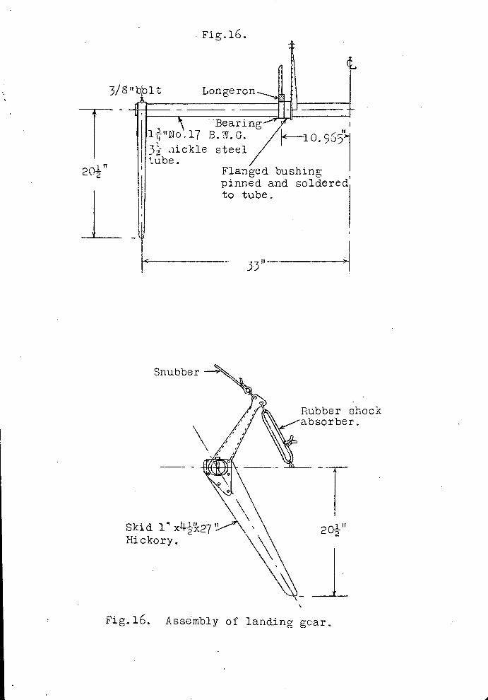
Snubber
Skid l'x Hickory.
Lbber shock sorber.
201-2 If
Fig.16.
3/ 8 bblt Longeron
0. iickle steel
20 Flanged bushing pinned and soldered to tube.
53"
Fig.16. Assembly of landing gear.

:o cH L_2 o f; O oJ
Bearing 2 required
5/8 U
1/2"
i/4-' drill
No.100 B.W.G. steel
12Flange bushing brazed to horn
Bore to fit tub
. 18 B.W.G.
Fig.17.
Bronze
No.18
steel. j
•) TF]T
.05 Horn 2 required
3/8"drill
k------ L.," 7/ _____
ti 0 0
flattened and tube[r l
I brazed on.
•L °,' If
Skid fitting 2 required IFig..l7 Details of landing gear.


![DIVISION I - Minnesota Department of Transportation ... · Web viewFor lifts thicknesses from 3 inches [75 mm] to 6 inches [150 mm] compact using both a pneumatic-tired and pad foot](https://static.fdocuments.in/doc/165x107/5b4dcb6c7f8b9af2438b534d/division-i-minnesota-department-of-transportation-web-viewfor-lifts-thicknesses.jpg)