The Liverpool Telescope Iain Steele Liverpool John Moores University.
Page 1
Liverpool Cruise Terminal
WIE12464-100-TN-14-2-2
Liverpool Cruise Terminal Technical Note – Cormorant Mitigation
This document has been prepared and checked in accordance with Waterman Group’s IMS (BS EN ISO 9001: 2015, BS EN ISO 14001: 2015 and BS OHSAS 18001:2007)
Issue Prepared by Checked & Approved by
Second Issue
Niall Machin Gavin Spowage
Associate Director Associate Director
1. Introduction
1.1. The shadow Habitat Regulations Assessment (HRA ref WIE12464-100-11-2-3-AA, Waterman
January 2019) for the Liverpool Cruise Terminal proposed ecological mitigation for cormorant
Phalacrocorax carbo in the form of a floating pontoon structure. MEAS and Natural England have
advised that the floating pontoon should be a permanent structure. This is secured by a planning
condition.
1.2. Small numbers of cormorant (up to 12) were recorded using on-site dockside structures in 2017
winter ornithological surveys. As the scheme will result in the loss of structures, particularly Princes
Jetty, used by roosting/resting cormorant during construction, a floating pontoon for roosting/resting
cormorant will be installed. To ensure the loss of the jetty is fully mitigated, the floating pontoon will
be a permanent installation. The new jetty will also provide cormorant resting/roosting locations.
1.3. This Note sets out further detail on the design and location of the floating pontoon and sits as part of
the strategic approach to cormorant mitigation in the wider Liverpool Waters vicinity of which the
Cruise Terminal is part.
1.4. A strategic approach to cormorant mitigation within the overall Liverpool Waters area is being
coordinated by Arup on behalf of Peel Land & Property (Ports) Ltd. The provisions within this
Technical Note are covered by and conform with the overarching strategic approach.
1.5. This Technical Note constitutes an Ecological Conservation Management Plan (ECMP) for
cormorants for the Liverpool Cruise Terminal development.
2. Pontoon design and location
Design
2.1. Floating platforms are used by wintering and other bird species, including cormorant, as night time
roosts and daytime resting areas. Cormorants utilising such structures have become a feature of
many of the UK’s urban areas where large bodies of water occur.
Waterman Infrastructure & Environment Limited
Merchants House, Wapping Road, Bristol, BS1 4RW www.watermangroup.com
Date: Date: October 2019
Client Name: Liverpool City Council
Document Reference: WIE12464-100-TN-14-2-2

Page 2
Liverpool Cruise Terminal
WIE12464-100-TN-14-2-2
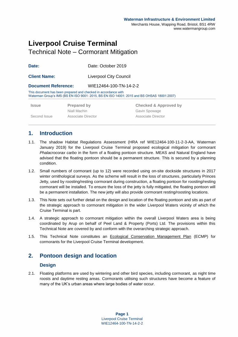
2.2. A schematic design is shown as Figure 1. This is designed to enable a single 3m by 3m pontoon to
be initially delivered by the neighbouring Isle of Man Ferry Terminal scheme in October 2019, with
additional pontoons being added to form a larger structure as other nearby developments, including
the Liverpool Cruise Terminal come forward.
Individual 3m by 3m pontoon design
2.3. Refer to Annex A for proposed pontoon design.
Larger joint pontoon design
2.4. It is known that a larger pontoon resource is required to jointly deliver cormorant mitigation for the
Isle of Man Ferry Terminal, Liverpool Cruise Terminal, Northern Relief Road and, potentially, the C02
project. Figure 1 therefore shows how four 3m by 3m blocks can form one single larger pontoon unit.
The final design may instead be a square 6m by 6m arrangement.
2.5. Whilst each individual scheme is expected to deliver appropriate mitigation for roosting/resting
cormorant displacement, there is a degree of ‘double counting’ of the birds involved. In particular,
the Isle of Man Ferry Terminal, Northern Relief Road and C02 developments will impact more or less
the same group of cormorants that currently rest/roost around West Waterloo Dock/Princes Dock
and the dockside structures. The cormorants using land impacted by Liverpool Cruise Terminal just
to the south would also interact with the West Waterloo/Princes Dock birds.
2.6. Therefore, it is appropriate for the individual developers to deliver a structure which could support
around 15-20 roosting/resting cormorant. The design in Figure 1 would accommodate upwards of
20 cormorants. It has been agreed that the relevant developers (Liverpool City Council, Isle of Man
Government Department of Infrastructure, and Peel Land & Property (Ports) Ltd) will jointly provide
this four-pontoon solution. However, a single 3m by 3m pontoon described in Annex A has been
installed by the Isle of Man Government under marine licence L/2019/00239/1, to meet the
requirements of condition 5.2.9 of that licence in advance of the other three pontoons (which can
then be attached to the single pontoon when they are installed), as the project timescales for the Isle
of Man scheme required the pontoon to be installed and in situ by 17th October 2019 at the latest.
That pontoon was installed on 16th October 2019. The date of installation of the second 3m x 3m
pontoon for the Liverpool Cruise Terminal is currently unknown.
Maintenance and Monitoring
2.7. The design will have an estimated life of at least 12 years with minimal maintenance. Minimal
management is required – just removal of bird droppings once per year (off site, not into the Dock).
2.8. The current pontoon and all subsequent pontoons, including the pontoon installed for the Liverpool
Cruise Terminal development, will be subject to an Adaptive Management Plan and annual winter
bird surveys. An Adaptive Management Plan has been drafted by Waterman (ref: WIE12464-100-
17-2-3) and forms an Appendix to the Liverpool Cruise Terminal CEMP document. The effectiveness
of the mitigation (i.e. the pontoon) will be reviewed annually and action taken to ensure appropriate
habitat for cormorant is maintained.
Page 3
Liverpool Cruise Terminal
WIE12464-100-TN-14-2-2
Figure 1: Proposed Cormorant Pontoon Design
Location
2.9. The floating pontoon(s) would be located in the eastern part of Princes Half Tide Dock, see Figure
2.

Page 4
Liverpool Cruise Terminal
WIE12464-100-TN-14-2-2
Figure 2: Proposed Cormorant Pontoon Location
3. Strategic approach
3.1. In their comments dated 18th March 2019 relating to the shadow HRA report submitted in support of
the planning application for the nearby Isle of Man Ferry Terminal proposed development (ref:
18F/3231), Natural England (NE) stated:
We are highly encouraged that development teams from a number of projects in the area are
working together to provide a combined mitigation pontoon. We have advised that a strategic
approach to mitigation would be the most beneficial approach to ensure impacts arising from the
number of developments is considered, therefore allowing for more certainty on deliverability of
mitigation within a holistic manner. We advise that a strategic mitigation strategy should be
provided and ideally in advance of projects coming forward so that the strategy can be agreed and
in place, therefore allowing a smooth process through the planning stages.
3.2. In response to NE’s advice, Peel, the site owners and holders of the outline permission for the
Liverpool Waters Masterplan have agreed to co-ordinate a strategic approach to cormorant mitigation
for Liverpool Cruise Terminal (LCT), Isle of Man Ferry Terminal (IoM), Northern Link Road (NLR)

Page 5
Liverpool Cruise Terminal
WIE12464-100-TN-14-2-2
and C02. Peel have identified a new permanent pontoon facility to be provided in Princes Half Tide
Dock – see Figure 2 above.
3.3. The final large joint pontoon structure would comprise 4 interlocking units forming a single structure
of sufficient size and design to deliver the mitigation for the IoM, LCT, NLR and C02 schemes, i.e.
catering for at least 20 cormorants.
3.4. Peel, in association with the individual developers, will oversee the Annual Monitoring of the pontoon
facility in terms of winter bird monitoring surveys. The facility will be subject to an Adaptive
Management Plan (AMP) which sets out any additional actions required for successful mitigation,
e.g. responding to the monitoring in terms of adaptations that may be required to the structure to
make it more suitable for cormorant. The AMP will also address management or maintenance
requirements and respond to further additions/additional structural elements/habitats should other
schemes come forward in the vicinity that require ecological mitigation of this sort.
3.5. The strategic approach to cormorant mitigation within the overall Liverpool Waters area, including
the AMP for the cormorant pontoons, is being coordinated by Arup on behalf of Peel Land & Property
(Ports) Ltd. The provisions within this Technical Note are covered by and conform with the
overarching strategic approach.

Page 6
Liverpool Cruise Terminal
WIE12464-100-TN-14-2-2
ANNEX A
Cormorant Pontoon – Design Basis Statement and Method Statement

REPORT
IOM Ferry Terminal – Bird Pontoon
Design Basis Statement
Client: Sisk
Reference: PB8850-RHD-ZZ-XX-RP-Z-0001
Status: Draft/P02
Date: 30 July 2019

P r o j e c t R e l a t e d
30 July 2019 DESIGN BASIS STATEMENT PB8850-RHD-ZZ-XX-RP-Z-0001 i
HASKONINGDHV UK LTD.
Burns House
Harlands Road
Haywards Heath
West Sussex
RH16 1PG
Maritime & Aviation
VAT registration number: 792428892
+44 1444 458551
royalhaskoningdhv.com
T
E
W
Document title: IOM Ferry Terminal – Bird Pontoon
Document short title: Design Basis Statement Reference: PB8850-RHD-ZZ-XX-RP-Z-0001
Status: P02/Draft Date: 30 July 2019
Project name: IOM Ferry Terminal Project number: PB8550
Author(s): Stephen Salmon
Drafted by: Stephen Salmon
Checked by: Mike Primrose
Date / initials: 26/07/2019
Approved by: Alistair Reid
Date / initials: 26/07/2019
Classification
Project Related
Disclaimer No part of these specifications/printed matter may be reproduced and/or published by print, photocopy, microfilm or byany other means, without the prior written permission of HaskoningDHV UK Ltd.; nor may they be used, without suchpermission, for any purposes other than that for which they were produced. HaskoningDHV UK Ltd. accepts noresponsibility or liability for these specifications/printed matter to any party other than the persons by whom it wascommissioned and as concluded under that Appointment. The integrated QHSE management system of HaskoningDHVUK Ltd. has been certified in accordance with ISO 9001:2015, ISO 14001:2015 and OHSAS 18001:2007.

P r o j e c t R e l a t e d
30 July 2019 DESIGN BASIS STATEMENT PB8850-RHD-ZZ-XX-RP-Z-0001 ii
Table of Contents
1 Introduction 1
2 Key Parameters 2
2.1 Geometry 2
2.2 Wind 2
2.3 Water Levels 2
2.4 Seabed Composition 2
2.5 Wave climate 2
2.6 Live loads 3
3 Results 4
3.1 Stability 4
3.2 Anchorage 4
4 Designers Risk Assessment 5
Appendix A - RSPB Design and Management of Rafts Note

P r o j e c t R e l a t e d
30 July 2019 DESIGN BASIS STATEMENT PB8850-RHD-ZZ-XX-RP-Z-0001 1
1 Introduction
The scope of the design comprises 1 No. 3 x 3m pontoon for bird roosting including Cormorants for a 12-year design life. The pontoon will be located in Princes Half-Tide Dock, Liverpool. The overall design is based on an adaptation of an existing RSPB design, as outlined in the RSPB Design and Management of Rafts notes, by forming the lower section in steel with upper section remaining as per the standard design. The RSPB design notes are included in Appendix A.
P r o j e c t R e l a t e d
30 July 2019 DESIGN BASIS STATEMENT PB8850-RHD-ZZ-XX-RP-Z-0001 2
2 Key Parameters
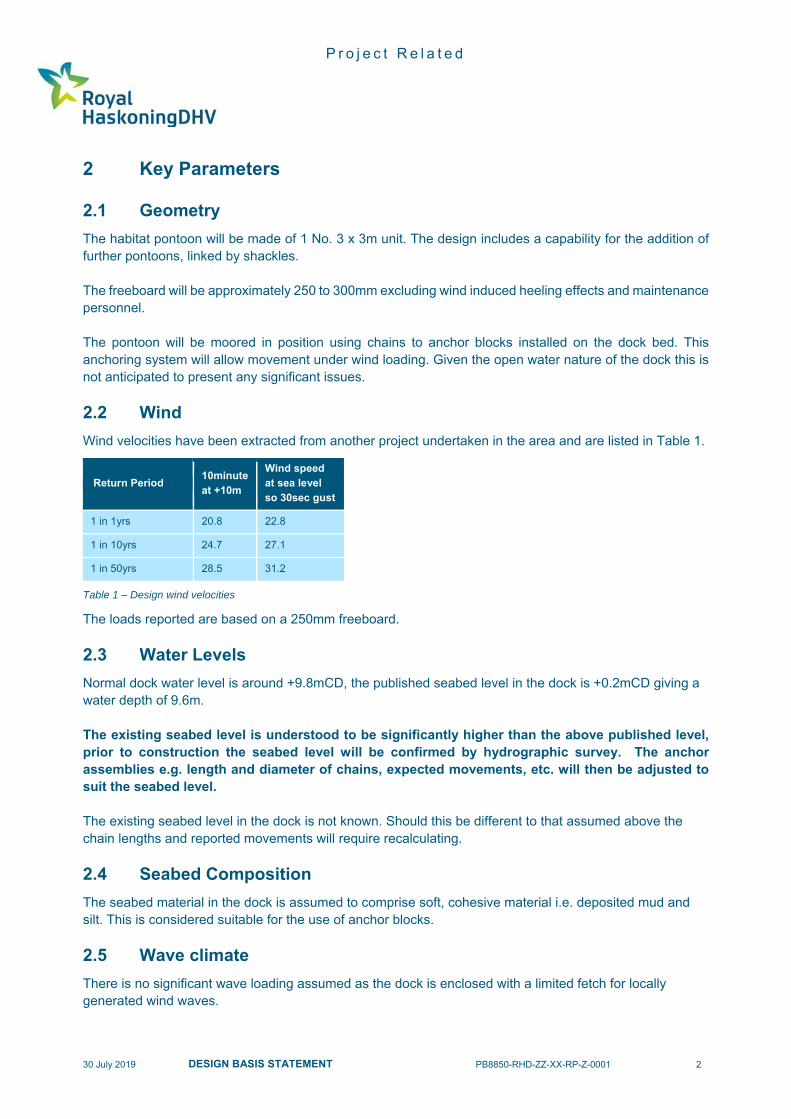
2.1 Geometry
The habitat pontoon will be made of 1 No. 3 x 3m unit. The design includes a capability for the addition of further pontoons, linked by shackles. The freeboard will be approximately 250 to 300mm excluding wind induced heeling effects and maintenance personnel. The pontoon will be moored in position using chains to anchor blocks installed on the dock bed. This anchoring system will allow movement under wind loading. Given the open water nature of the dock this is not anticipated to present any significant issues.
2.2 Wind
Wind velocities have been extracted from another project undertaken in the area and are listed in Table 1.
Return Period 10minute at +10m
Wind speed at sea level so 30sec gust
1 in 1yrs 20.8 22.8
1 in 10yrs 24.7 27.1
1 in 50yrs 28.5 31.2
Table 1 – Design wind velocities
The loads reported are based on a 250mm freeboard.
2.3 Water Levels
Normal dock water level is around +9.8mCD, the published seabed level in the dock is +0.2mCD giving a water depth of 9.6m. The existing seabed level is understood to be significantly higher than the above published level, prior to construction the seabed level will be confirmed by hydrographic survey. The anchor assemblies e.g. length and diameter of chains, expected movements, etc. will then be adjusted to suit the seabed level. The existing seabed level in the dock is not known. Should this be different to that assumed above the chain lengths and reported movements will require recalculating.
2.4 Seabed Composition
The seabed material in the dock is assumed to comprise soft, cohesive material i.e. deposited mud and silt. This is considered suitable for the use of anchor blocks.
2.5 Wave climate
There is no significant wave loading assumed as the dock is enclosed with a limited fetch for locally generated wind waves.

P r o j e c t R e l a t e d
30 July 2019 DESIGN BASIS STATEMENT PB8850-RHD-ZZ-XX-RP-Z-0001 3
2.6 Live loads
A uniformly distributed load of 0.40kPA and point load of 1.00kN has been assumed. This matches the recommend guidance provided in BS EN 1991-1 Table 6.10 for a Category H roof i.e. not accessible except for normal maintenance and repair. Ad additional load case of 3 No. persons (equivalent to 0.75kN each) on one side has also been assumed. This allows for 3 maintenance personnel or other unauthorised access. Cormorants have been proposed as the primary users of the pontoon accessing it by flying. These birds have typical body masses of up to 5.0kg. Consequently, they are not anticipated to have any significant impact on the freeboard or stability of the pontoon. By inspection their live loading is lower than that assumed in the design.

P r o j e c t R e l a t e d
30 July 2019 DESIGN BASIS STATEMENT PB8850-RHD-ZZ-XX-RP-Z-0001 4
3 Results
To achieve an initial 250-300mm freeboard with all the timber and gravel in-situ 762mm diameter tubes filled with polystyrene is required. The polystyrene will reduce the risk of the pontoon sinking should the tubes be perforated. These tanks are to act as support for the decking with additional angles to support the planking. The tubes will be sealed with square end plates that will allow welding to the square frame that holds the deck in place. Diagonal bracing will be attached to the end plates to secure the floatation tanks. The freeboard and trim of the pontoon is adjustable via the addition and positioning of steel plates on the deck (these will be gravel covered). Freeboard corrections will be achieved by adding the plates at the centre of the pontoon. Trim corrections will be made by adding plates to the edges of the pontoon. It should be noted that any reductions in freeboard beyond the assumed 250-300mm will have a disproportionate effect on reserve buoyancy due to the tube shape.
3.1 Stability
Full live load Max total load =0,40kN/m2 x 3m x 3m = 3.60kN With this load the freeboard will reduce by 30mm. With the UDL loading on one side only the heel will be in the region of 1.0° Therefore the unit is deemed stable for the expected use. Additional point loads Max total load = 3 x 0.75kN = 2.25kN With this load the freeboard will reduce by 20mm. With this loading on one side only the heel will be in the region of 1.2° Therefore the unit is deemed stable for the expected use.
3.2 Anchorage
The anchor assemblies comprise catenary chains attached to sinkers positioned on the seabed. Using a 12.0m length 25kg/m catenary chain the anchor sinkers need to have a submerged weight of 250kg. This is equivalent to a dry concrete mass of 420kg or 280kg of steel.

P r o j e c t R e l a t e d
30 July 2019 DESIGN BASIS STATEMENT PB8850-RHD-ZZ-XX-RP-Z-0001 5
4 Designers Risk Assessment
No. Risk Impact Mitigation Residual Risk
1
Floating structure that, though designed for wild life, will occasionally be accessed by people
Instability could result in operative having an unplanned entry to the water.
Structure designed to have good stability will little tilt when unevenly loaded.
Operatives to wear life jackets when accessing the pontoons.
Operatives to be given adequate training/instruction as to safe working practice.
Hand railing will not be installed as that would negatively impact the purpose of the structure.
Typical risks of working near water. Suitable procedures need to be in place.
2 Floating structure is within an active area
Significant movement of the pontoons could risk other structures within the basin
Movement kept below reasonable limit for design winds from 1:50year event
Supports on each side to take full wind load therefore there will be share capacity in the perpendicular anchors that will give appropriate safety factor.
Under extreme conditions the anchor blocks could be dragged a short distance on the seabed and may require repositioning
3 Corrosion of floatation tanks
Corrosion could eventually result in a hole in a take that would result in its loss of buoyancy
Tanks filled with expanding foam such as even with a hole water will not be able to fill the tanks.
Significant areas of corrosion could allow the foam to be damaged and lost. An appropriate inspection regime is recommended
4 Lifting
The pontoon will have to be transferred into the water by lifting on slings.
Structure kept to minimum weight
Tanks integral part of structure so slings under tanks during lifting not anticipated to put undue stresses into pontoon.
Typical risks of lifting large object into water. Suitable method statements would need to be produced
P r o j e c t R e l a t e d
Appendix A – RSPB Design and Management of Rafts Note

The RSPB
UK Headquarters
The Lodge
Sandy
Bedfordshire SG19 2DL
Tel: 01767 693690
The RSPB
Northern Ireland Headquarters
Belvoir Park Forest
Belfast BT8 7QT
Tel: 028 9049 1547
The RSPB
Scotland Headquarters
Dunedin House
25 Ravelston Terrace
Edinburgh EH4 3TP
Tel: 0131 311 6500
The RSPB
Wales Headquarters
Sutherland House
Castlebridge
Cowbridge Road East
Cardiff CF11 9AB
Tel: 029 2035 3000
www.rspb.org.uk Registered charity England and Wales no 207076, Scotland no SC037654
Design of management of rafts
Rafts are a useful way of providing island habitat in areas of deep or fluctuating water levels. Their
purpose is to improve breeding success by providing areas safe from flooding, disturbance or
predation. Rafts are unlikely to attract terrestrial predators and so are useful where islands would be
too close to shore for safety. They also provide wildfowl with loafing spots and are often used as
resting places by various bird species during the winter.
Main factors to consider when making a raft There are many conflicting requirements when constructing a nesting raft.
• The ability to float, preferably with the deck just above the water line.
• The ability to rise and fall easily with the water over the maximum flood range.
• Stability, so that the raft is not tipped or spun by current, waves or wind.
• A dry, sheltered nest site, which does not attract the attention of crows or other avian predators.
The nest area must be high enough not to be swamped by storm waves.
• Means of access and some protection from waves and current for young birds.
• Harmonious blending with the surroundings if possible.
• Practical factors e.g. water not excessively deep, lake shore accessible by vehicle, for bringing in
boat, raft and materials, and for regular maintenance checks.
• On SSSIs, formal consent may be required from NE, SNH or CCW.
Construction Although rafts vary in character and design, some basic considerations apply to each.
1. Timber rafts tend to absorb water and sink, although pine or other light wood floats better than
heavy timber. In most cases, additional floats must be used if the raft is to last for more than one
season.
2. Flotation blocks: Small rafts can be floated with plastic 4.5 litre containers. Slightly larger rafts
will stay afloat with 22 litre plastic drums. Rafts in the range of 1.2 - 1.8 m in dimension require
closed cell polystyrene blocks, polystyrene scraps, airtight metal drums (including old oil drums).
Polystyrene is easily held in place and can be adjusted to achieve right buoyancy. It should be
packed into strong polythene to prevent it from breaking up and littering the environment. Metal
drums need to be weighted so that they do not float too high. The flotation blocks must be
thoroughly cleaned before they are brought to the site to prevent pollution. Annual checks and
maintenance is important to ensure that the raft remains secure and firm, and that the flotation
devices are not disintegrating or leaking.
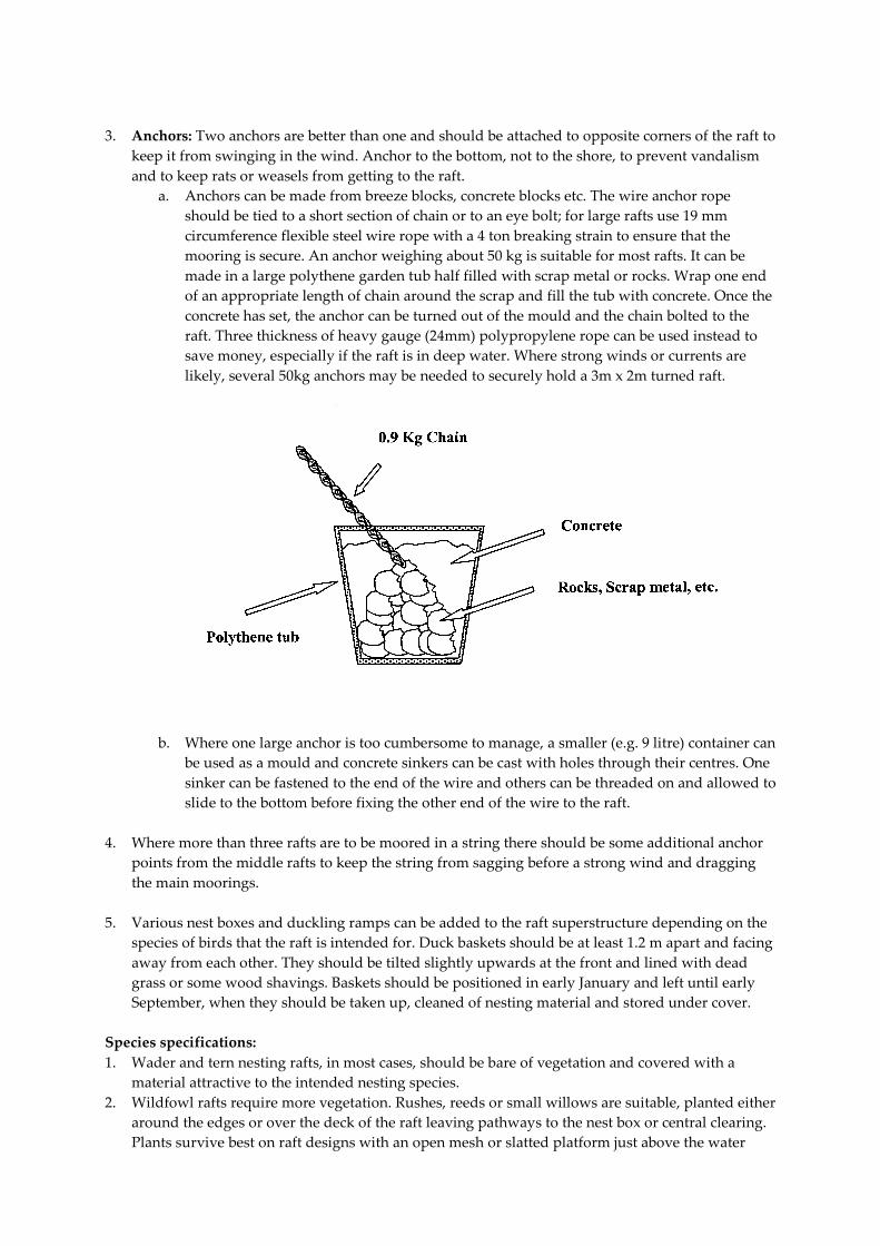
3. Anchors: Two anchors are better than one and should be attached to opposite corners of the raft to
keep it from swinging in the wind. Anchor to the bottom, not to the shore, to prevent vandalism
and to keep rats or weasels from getting to the raft.
a. Anchors can be made from breeze blocks, concrete blocks etc. The wire anchor rope
should be tied to a short section of chain or to an eye bolt; for large rafts use 19 mm
circumference flexible steel wire rope with a 4 ton breaking strain to ensure that the
mooring is secure. An anchor weighing about 50 kg is suitable for most rafts. It can be
made in a large polythene garden tub half filled with scrap metal or rocks. Wrap one end
of an appropriate length of chain around the scrap and fill the tub with concrete. Once the
concrete has set, the anchor can be turned out of the mould and the chain bolted to the
raft. Three thickness of heavy gauge (24mm) polypropylene rope can be used instead to
save money, especially if the raft is in deep water. Where strong winds or currents are
likely, several 50kg anchors may be needed to securely hold a 3m x 2m turned raft.
b. Where one large anchor is too cumbersome to manage, a smaller (e.g. 9 litre) container can
be used as a mould and concrete sinkers can be cast with holes through their centres. One
sinker can be fastened to the end of the wire and others can be threaded on and allowed to
slide to the bottom before fixing the other end of the wire to the raft.
4. Where more than three rafts are to be moored in a string there should be some additional anchor
points from the middle rafts to keep the string from sagging before a strong wind and dragging
the main moorings.
5. Various nest boxes and duckling ramps can be added to the raft superstructure depending on the
species of birds that the raft is intended for. Duck baskets should be at least 1.2 m apart and facing
away from each other. They should be tilted slightly upwards at the front and lined with dead
grass or some wood shavings. Baskets should be positioned in early January and left until early
September, when they should be taken up, cleaned of nesting material and stored under cover.
Species specifications:
1. Wader and tern nesting rafts, in most cases, should be bare of vegetation and covered with a
material attractive to the intended nesting species.
2. Wildfowl rafts require more vegetation. Rushes, reeds or small willows are suitable, planted either
around the edges or over the deck of the raft leaving pathways to the nest box or central clearing.
Plants survive best on raft designs with an open mesh or slatted platform just above the water
line, covered with moisture-holding mulch in which the plants can root and through which they
can reach the water.
Some raft models The area and water characteristics determine the best design for a raft. Some of the designs used on
RSPB reserves are described below as a guide.
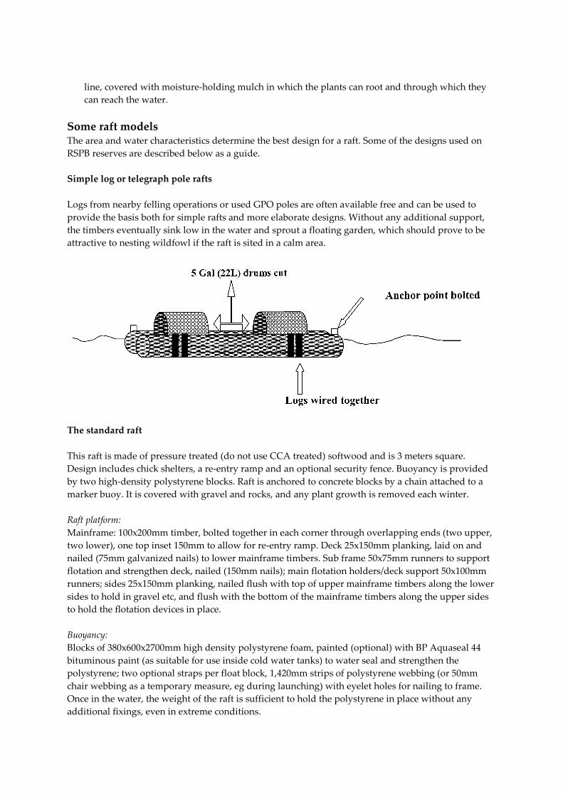
Simple log or telegraph pole rafts
Logs from nearby felling operations or used GPO poles are often available free and can be used to
provide the basis both for simple rafts and more elaborate designs. Without any additional support,
the timbers eventually sink low in the water and sprout a floating garden, which should prove to be
attractive to nesting wildfowl if the raft is sited in a calm area.
The standard raft
This raft is made of pressure treated (do not use CCA treated) softwood and is 3 meters square.
Design includes chick shelters, a re-entry ramp and an optional security fence. Buoyancy is provided
by two high-density polystyrene blocks. Raft is anchored to concrete blocks by a chain attached to a
marker buoy. It is covered with gravel and rocks, and any plant growth is removed each winter.
Raft platform:
Mainframe: 100x200mm timber, bolted together in each corner through overlapping ends (two upper,
two lower), one top inset 150mm to allow for re-entry ramp. Deck 25x150mm planking, laid on and
nailed (75mm galvanized nails) to lower mainframe timbers. Sub frame 50x75mm runners to support
flotation and strengthen deck, nailed (150mm nails); main flotation holders/deck support 50x100mm
runners; sides 25x150mm planking, nailed flush with top of upper mainframe timbers along the lower
sides to hold in gravel etc, and flush with the bottom of the mainframe timbers along the upper sides
to hold the flotation devices in place.
Buoyancy:
Blocks of 380x600x2700mm high density polystyrene foam, painted (optional) with BP Aquaseal 44
bituminous paint (as suitable for use inside cold water tanks) to water seal and strengthen the
polystyrene; two optional straps per float block, 1,420mm strips of polystyrene webbing (or 50mm
chair webbing as a temporary measure, eg during launching) with eyelet holes for nailing to frame.
Once in the water, the weight of the raft is sufficient to hold the polystyrene in place without any
additional fixings, even in extreme conditions.

Mooring:
Mooring ring bolted through center of mainframe timber (bolt fixed with two nuts so that it can
swivel freely), connected preferably to a chain or a 20mm diameter hawser-lay polypropylene rope
(which will not rot, but can be chafed), with hard eyes and shackles each end. Tether a 30-inch
circumference marker buoy to the raft end of the chain or rope with a length of polypropylene rope to
allow the raft to be detached, without having to pull up or lose the anchor.
Anchor:
Multiple small weights (up to 1m3 concrete as a total) for ease of transport. Four buckets 250mm high
by 300mm diameter of concrete, eyebolt set in centre; weights connected in pairs by shackles to
300mm lengths of chain; fixed to mooring by placing two pairs of weights together with the
connecting chains forming a cross, and attaching the mooring rope shackle to the point where the
chains cross. Exposed sites where wind and waves are strong may require more anchor weights.
Shelters (to protect from rain):
These comprise 1m long 25x150mm planks located in opposite corners, nailed flat onto end of upper
mainframe timber, side plank and 50x75mm end block.
Gravel covering:
Preferably of 15mm-25mm gravel with larger pieces and rocks to provide shelter, and give sufficient
weight to push running board down to water level.
Re- entry system (for chicks falling overboard):
These are located on opposite (lee) side of raft to the mooring ring: running board 3m, 25x150mm
plank nailed to bottom of the two lower mainframes. Ramp (1.5m, 25x150mm plank) sloping up to top
corner of mainframe, supported by up stand, nailed. Block gap under raft behind ramp with
25x150mm skirt plank.
Optional removable security fence:
These comprise four frames 230mm by 0.3m, made from 50x50mm planks covered with 25mm chicken
wire, bolted along each side and fixed at top corners.

A floating wildfowl nest for use on rivers
This design, successfully used on the Ray, near Oxford, is intended to overcome the problems posed
by strong currents, which make it difficult for wildfowl to nest successfully on rivers. Chick survival is
best where the floating nest is sited on a quiet backwater with gently sloping banks so that, when a
chick leaves the nest, it can get to the shore and climb out despite the current.
1. Drive a suitable length of 50mm diameter steel pipe into the riverbed to provide an anchor pole
on which the floating nest can rise and fall with changes in water level.
2. Cut out a circular platform from marine plywood and cut a hole in its centre so that it fits over the
anchor pipe.
3. Screw three boards to the circular plywood piece, so that they form an equilateral triangle to make
a frame underneath the platform for the floats.
4. Strap three 4.5 litre plastic or metal tins to the triangular frame, one each side. If metal tins are
used, they should be well painted with bitumen paint and coated inside with a spoonful of old
engine oil before capping.
5. Attach three metal struts, evenly spaced, to the edge of the platform, joined at the upper end to a
ring that fits over the anchor pipe. This upper ring, with the hole in the platform, forms the
bearing on which the nest rises and falls on the pipe.
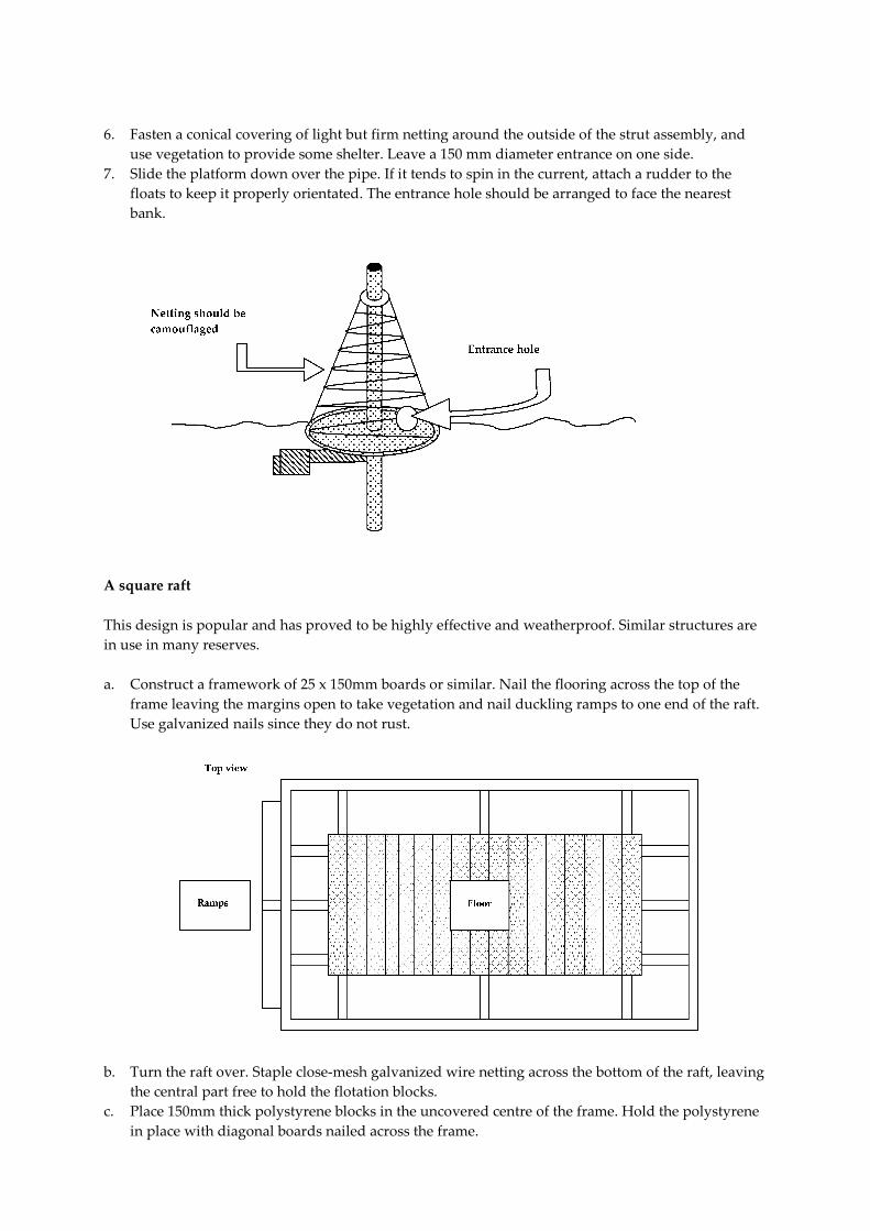
6. Fasten a conical covering of light but firm netting around the outside of the strut assembly, and
use vegetation to provide some shelter. Leave a 150 mm diameter entrance on one side.
7. Slide the platform down over the pipe. If it tends to spin in the current, attach a rudder to the
floats to keep it properly orientated. The entrance hole should be arranged to face the nearest
bank.
A square raft
This design is popular and has proved to be highly effective and weatherproof. Similar structures are
in use in many reserves.
a. Construct a framework of 25 x 150mm boards or similar. Nail the flooring across the top of the
frame leaving the margins open to take vegetation and nail duckling ramps to one end of the raft.
Use galvanized nails since they do not rust.
b. Turn the raft over. Staple close-mesh galvanized wire netting across the bottom of the raft, leaving
the central part free to hold the flotation blocks.
c. Place 150mm thick polystyrene blocks in the uncovered centre of the frame. Hold the polystyrene
in place with diagonal boards nailed across the frame.

d. Turn the raft right way up. Cut out blocks of rush, willow etc. to fit into the margins of the frame.
Fit anchor bolts to two opposite corners. Fix a nesting box or basket if required. You can cover the
raft with some gravel. Finally, tow the raft into the position and anchor it firmly.
A heavier variation:
The raft described below is very successful when attracting terns to nest. Bare shingle is required for
the nesting, but a completely exposed raft results in high chick mortality. At about one week old, tern
chicks leap overboard at the slightest disturbance. This can be prevented by providing them with
small shelters to hide underneath.
1. Drill the sleepers as indicated in the diagram, using a
brace and a bit, and bolt them together with eight
250mm coach bolts. Drill and fix anchor bolts in the
end sleepers.
2. Drill and bolt the cross members to the side sleepers.
These are required to make a rigid structure and to
resist the upward pressure of the floats.
3. Nail the side battens into position; these help hold the
shingle in place.
4. There are two ways to floor the raft. One is to trap plastic-coated chain link fencing, covered in
heavy-duty polythene, under the cross braces. Staple the fencing firmly to the sleepers.
Alternatively, nail old garage doors or other suitable sturdy timber to the cross members and
spread the flooring with a layer of concrete to help keep the shingle in place.
5. Float the raft. Unless you have mechanical help, placing approximately 0.8 cubic metres of
polystyrene blocks under the raft for flotation will require a number of water-hardy volunteers.
6. The amount of polystyrene needed varies with the weight of the raft so trials are necessary.
Provide some extra flotation to compensate for the shingle, which is added afterwards. The
polystyrene stays in place between the sleepers due to its buoyancy and should not need
fastening.
7. Spread a layer of shingle over the flooring.
8. Fix ramps or walls to the rafts sides, place a shelter on it, tow it into position and anchor it by
means of bolts in the end sleepers.

Welded Rafts
These two models were designed for the specific needs of a particular area. They require a great deal
of skills and therefore are only suitable if none of the previous ones can be used. The designs shown
have proved to have an estimated life of at least 12 years with minimal maintenance. These types
depend on availability of suitable welding equipment and skills, and sheet-metal float tanks used by
gravel companies for ferrying electrical equipment around wet pits.
Type A
Weld together three float tanks and attach a rim of logs with welded metal straps. To moor the raft, fix
a wire anchor rope to a 50 kg scrap iron or concrete anchor. This simple but strong raft gives a surface
area of 6.7 square metres. It successfully attracts ducks and geese, but has two disadvantages. It is so
buoyant that the nest floats at least a foot above the water so that, unless a ramp is attached to help
them, once the chicks leave the raft they cannot return. Soil ultimately dries out or is dislodged and
must be replaced at intervals along with fresh vegetation.
Type B
This rather elaborate design features a semi-flexible welded frame, which makes the raft very durable
in exposed conditions. The float tanks are the same size as in the previous design; the sleepers are
topped with a grid that holds nesting cover.
Construction:
• Weld the frame together and to the float tanks. Weld two anchor bolts to opposite corners.
• Manoeuvre the completed frame into the water.
• Slide the sleepers into position. Leave gaps between the pairs of sleepers so that plant roots can
reach the water.
• Cover the top of the frame’s central section with narrow-mesh galvanized metal.
• Fix the nesting boxes on top of the floats
• Cover the mesh with mulch or soil and suitable plants. Plant up the nesting boxes.
• Tow the raft into position and anchor from the anchor bolts.
Wildlife
Design of rafts 3/08

REPORT
IOM Ferry Terminal – Bird Pontoon
Method Statement
Client: Sisk
Reference: PB8850-RHD-ZZ-XX-RP-Z-0002
Status: Draft/P02
Date: 30 July 2019

P r o j e c t R e l a t e d
30 July 2019 METHOD STATEMENT PB8850-RHD-ZZ-XX-RP-Z-0002 i
HASKONINGDHV UK LTD.
Honeycomb
Edmund Street
Liverpool
L3 9NG
Maritime & Aviation
VAT registration number: 792428892
+44 151 236 2944
royalhaskoningdhv.com
T
E
W
Document title: IOM Ferry Terminal – Bird Pontoon
Document short title: Method Statement Reference: PB8850-RHD-ZZ-XX-RP-Z-0002
Status: P02/Draft Date: 30 July 2019
Project name: IOM Ferry Terminal Project number: PB8850
Author(s): Mike Primrose
Drafted by: Mike Primrose
Checked by: Ben Hughes
Date / initials: 25/07/2019
Approved by: Alistair Reid
Date / initials: 26/07/2019
Classification
Project Related
Disclaimer No part of these specifications/printed matter may be reproduced and/or published by print, photocopy, microfilm or by any other means, without the prior written permission of HaskoningDHV UK Ltd.; nor may they be used, without suchpermission, for any purposes other than that for which they were produced. HaskoningDHV UK Ltd. accepts noresponsibility or liability for these specifications/printed matter to any party other than the persons by whom it wascommissioned and as concluded under that Appointment. The integrated QHSE management system of HaskoningDHVUK Ltd. has been certified in accordance with ISO 9001:2015, ISO 14001:2015 and OHSAS 18001:2007.

P r o j e c t R e l a t e d
30 July 2019 METHOD STATEMENT PB8850-RHD-ZZ-XX-RP-Z-0002 ii
Table of Contents
1 Introduction 1
1.1 Site Location 1
2 Pontoon and Anchor Assemblies 2
3 Installation 3
3.1 Off-Site Fabrication 3
3.2 Survey 3
3.3 Lifting into the Dock 3
3.4 Means of Access 3
3.5 Gravel Placement 3
3.6 Anchor Assembly Installation 3
3.7 Mooring into Final Location 3
4 Maintenance 4
5 Decommissioning 5
P r o j e c t R e l a t e d
30 July 2019 METHOD STATEMENT PB8850-RHD-ZZ-XX-RP-Z-0002 1
1 Introduction
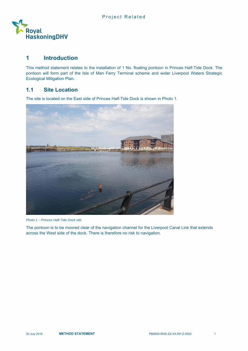
This method statement relates to the installation of 1 No. floating pontoon in Princes Half-Tide Dock. The pontoon will form part of the Isle of Man Ferry Terminal scheme and wider Liverpool Waters Strategic Ecological Mitigation Plan.
1.1 Site Location
The site is located on the East side of Princes Half-Tide Dock is shown in Photo 1.
Photo 1 – Princes Half-Tide Dock site
The pontoon is to be moored clear of the navigation channel for the Liverpool Canal Link that extends across the West side of the dock. There is therefore no risk to navigation.

P r o j e c t R e l a t e d
30 July 2019 METHOD STATEMENT PB8850-RHD-ZZ-XX-RP-Z-0002 2
2 Pontoon and Anchor Assemblies
The pontoon will comprise a below water level welded steel frame with an above water timber covering (pressure but not CCA treated softwood timber). The design is an adaptation of ‘the standard raft’ described in RSPB document Design and Management of Rafts. The anchor assemblies comprise steel sinkers and standard anchor chains. All the above components will be fabricated off-site. The topside of the pontoon will be covered in a layer of washed gravel.

P r o j e c t R e l a t e d
30 July 2019 METHOD STATEMENT PB8850-RHD-ZZ-XX-RP-Z-0002 3
3 Installation
3.1 Off-Site Fabrication
The pontoon and anchor assemblies will be fabricated off-site and transported to Princes Half Tide Dock by road.
3.2 Survey
A hydrographic survey of the dock will be undertaken to confirm the seabed level which will then allow the final mooring locations to be confirmed. In particular the water depth will allow the sinker positions and weights to be confirmed.
3.3 Lifting into the Dock
The pontoon will be lifted into the dock by a small mobile crane or HIAB, located alongside one of the quay walls.
3.4 Means of Access
A safe means of access between the pontoon and quay will be set up. Operatives working on the pontoon will also wear correct Personal Protective Equipment (PPE) which will include self-inflating life preservers at all times.
3.5 Gravel Placement
The gravel covering to the pontoon topside will be placed by hand and raked level. All gravel will be pre-washed to minimise dust.
3.6 Anchor Assembly Installation
The anchor assemblies will be attached to floatation bags and then be lifted into the dock by the mobile crane or HIAB. A small craft will then tow each of the anchor assemblies to the anchor locations and release the sinkers. The floatation bags will remain attached to the free end of the mooring chains.
3.7 Mooring into Final Location
The completed pontoon ill then be towed to the final location by a small craft. Each of the free anchor chains will then be attached to the pontoon and the floatation bags removed and retained.
P r o j e c t R e l a t e d
30 July 2019 METHOD STATEMENT PB8850-RHD-ZZ-XX-RP-Z-0002 4
4 Maintenance
The annual maintenance of the pontoon topside is envisaged to be undertaken in-situ. Access to the pontoon will be via a small boat. The pontoon design allows for the maintenance access in terms of flotation and stability. The anchor assemblies are not envisaged to require maintenance in the 12-year design life.

P r o j e c t R e l a t e d
30 July 2019 METHOD STATEMENT PB8850-RHD-ZZ-XX-RP-Z-0002 5
5 Decommissioning
The decommissioning of the pontoon is envisaged to be undertaken after a period of 12 years. The pontoon will be disconnected, temporarily positioned against a quay wall and a safe means of access installed using the previously described procedure. The gravel covering of the topside will be removed by hand and disposed of off-site. The pontoon will then be disconnected from any further pontoons, if installed, prior to being lifted from the dock by small mobile crane or HIAB. The pontoon will be then be disposed of off-site with transportation by road. There are two possibilities envisaged with regards to removal of the anchor assemblies.
1. The sinkers on the seabed may have embedded into what is assumed to be a soft mud / silt material. If this is the case it is proposed to cut the chains at seabed level. This would leave the sinkers in place as they pose no risk to navigation or to the environment. This will also mitigate the need for any air-lifting or dredging works that would otherwise be required to extract the sinkers.
2. In the event the sinkers remain on the seabed or to a shallow embedment, it is proposed they will
be lifted by floatation bag, be towed to near one of the quay walls and be lifted by small mobile crane or HIAB.
In either option the removed elements of the anchor assemblies will be then disposed be of off-site with transportation by road. The works in the dock will be undertaken using a diving contractor operating from a quay side.

A
21
EA
0015
A
0015
3000
3000
4No. 150x75x18 PFC FRAMING BEAMS
B
D
C
400
400
1100
1100
1
0015
1
0015
TIMBER RAMP
A E
4No. 150x75x18 PFC FRAMING BEAMS
SOLID WATERTIGHT BULKHEAD PLATES (2No. PAIRS)
TWIN TUBES IN PAIRS DESIGN INCORPORATING 2No. 762 x 8 CHS FOR FREEBOARD AND STABILITY WELDED TO BULKHEAD PLATES
B DC
3No. 150x75x18 PFC DECK BEAMS AS JOISTS
1500 1500
400 400
TIMBER EDGING PLANKS FIXED TO FRAMING PFC'S
50thk. GRAVEL
ASSUMED WATER LINE
250
21
ASSUMED WATER LINE
A EB DC
ASSUMED WATER LINE
250
Honeycomb, Edmund StreetLiverpool L3 9NG
Tel: +44 (0)151 236 2944Email: [email protected]
Website: www.royalhaskoningdhv.com
Royal HaskoningDHV UK Ltd.c
REVISION
TITLE
SCALEAT A1
REF.DATE
APPROVEDCHECKEDDRAWN
DRAWING No.
PROJECT
CLIENT
REVISIONS
REV DATE DESCRIPTION DRW CHK APR
SUITABILITY
As indicated
ISLE OF MAN FERRY TERMINAL
PONTOON GENERALARRANGEMENT
DD MP AR
07/10/19
P1.0S3PB8850-RHD-XX-XX-DR-C-0015
DD MP AR12.07.2019 FIRST ISSUEP1.0
PB8850-RHD-XX-XX-DR-C-0015
1 : 25
DECK PLAN
1 : 10
VIEW ON A
1 : 25
FRONT ELEVATION
3D VIEW OF PONTOON
NOTES1. THIS DRAWING SHOWS A CONCETPUAL GENERAL
ARRANGEMENT FOR THE PROPOSED COMPENSATORY HABITAT PONTOON.
2. ALL DIMENSION IN MILLIMETERS
3. STEEL S2 75 WITH C5-M DURABILITY HIGH COATING TO BS EN 12944.
4. TUBES TO BE FILLED WITH CUT POLYSTYRENE BLOCKS
5. 8No. ANCHOR BLOCKS AND CHAINS TBC BASED ON FINAL WATER DEPTH.
6. ALL WELDS TO BE 6mm FILLET WELDS.
7. GRAVEL TO BE NOMINALLY 50THK. 20mm SINGLE SIZED PRE-WASHED.
1 : 10
SECTION B-B