LIVE14 tDomore:2007 t0506 priced.qxd - Direct Automation · · 2014-07-01Client/Server Protocol...
14
1-800-633-0405 e38-26 Programmable Controllers Volume 14 Specialty Modules The Do-more H2 Series PLC supports the following specialty modules. Ethernet Communication Modules Part Number Description H2-ECOM100 100MBit Ethernet Communication Module H2-ECOM (No longer available) 10Base-T Ethernet Module Serial Communication Modules Part Number Description H2-SERIO 3-port RS-232 Serial I/O Module H2-SERIO-4 3-port RS-232/RS-485 Serial I/O Module Ethernet Remote I/O Modules Part Number Description H2-ERM 10Base-T Ethernet Remote Master Module H2-EBC100 100MBit Ethernet Base Controller H2-EBC (No longer available) 10Base-T Ethernet Base Controller High Speed I/O Modules Part Number Description H2-CTRIO High Speed Counter Interface Module H2-CTRIO2 High Speed Counter Interface Module Input Simulator Module Part Number Description F2-08SIM 8-point Input Simulator
Transcript of LIVE14 tDomore:2007 t0506 priced.qxd - Direct Automation · · 2014-07-01Client/Server Protocol...

1 - 8 0 0 - 6 3 3 - 0 4 0 5e38-26 Programmable ControllersVolume 14
Specialty Modules
The Do-more H2 Series PLC supports the following specialty modules.
Ethernet Communication Modules
Part Number Description
H2-ECOM100 100MBit Ethernet Communication Module
H2-ECOM(No longer available)
10Base-T Ethernet Module
Serial Communication Modules
Part Number Description
H2-SERIO 3-port RS-232 Serial I/O Module
H2-SERIO-4 3-port RS-232/RS-485 Serial I/O Module
Ethernet Remote I/O Modules
Part Number Description
H2-ERM 10Base-T Ethernet Remote Master Module
H2-EBC100 100MBit Ethernet Base Controller
H2-EBC (No longer available)
10Base-T Ethernet Base Controller
High Speed I/O Modules
Part Number Description
H2-CTRIO High Speed Counter Interface Module
H2-CTRIO2 High Speed Counter Interface Module
Input Simulator Module
Part Number Description
F2-08SIM 8-point Input Simulator

w w w . a u t o m a t i o n d i r e c t . c o m Programmable Controllers e38-27
CompanyInformation
SystemsOverview
ProgrammableControllers
Field I/O
Software
C-more & other HMI
Drives
SoftStarters
Motors &Gearbox
Steppers/Servos
Motor Controls
ProximitySensors
Photo Sensors
Limit Switches
Encoders
CurrentSensors
PressureSensors
TemperatureSensors
Pushbuttons/Lights
Process
Relays/Timers
Comm.
TerminalBlocks & Wiring
Power
CircuitProtection
Enclosures
Tools
Pneumatics
Appendix
ProductIndex
Part #Index
Volume 14
H2-ECOM100 <--->
OverviewEthernet Communications Modules offerfeatures such as:
• High-speed peer-to-peer networking of PLCs
• Fast updates with Do-more DesignerSoftware
• High-performance access for HumanMachine Interface (HMI), ERP, MES orother Windows-based software
• Industry standard Modbus TCPClient/Server Protocol
Simple connectionsUse Category 5 UTP cables which can berun up to 100 meters between nodes. Ifneeded, use repeaters to extend distancesand expand the number of nodes.
Our HA-TADP (10/100Base-T) PC networkadapter card and Stride Ethernet switchesare compatible with the ECOM modules.See the Communications Products sectionfor information on these items.
Specifications H2-ECOM100Communications 10/100Base-T Ethernet
Data Transfer Rate 100 Mbps max.
Link Distance 100 meters (328 ft)
Ethernet Port RJ45
Ethernet Protocols TCP/IP, IPX, Modbus TCP,DHCP, HTML configuration
Power Consumption 300 mA @ 5 VDC
See the Communicationssection for details on
Ethernet Switches
Message is sent outof port only
connected to device
Message in from a device
Modbus TCP communications architecture
NetEdit 3 ConfigurationSoftwareNetEdit 3 Configuration Software isincluded in the free Do-more Designersoftware. Use NetEdit 3 to configure theECOM modules for your network. Flexibleaddressing allows you to use your choiceof protocols and identification methods.Assign each module a number, a name orboth. You don’t have to use an IP address,but you can if it’s necessary for yournetwork. NetEdit 3 uses two protocols forPC-to-PLC communications: IPX andTCP/IP. The NetEdit 3 screen displays allidentifiers and troubleshooting informa-tion for each module on the network. Youcan use NetEdit 3 to adjust parameters forPLC-to-PLC communications by clickingon Advanced Settings. The network iden-tifiers can also be changed from Do-moreDesigner software.
Specialty Modules
H2-ECOM100
TheH2-ECOM100 supports the
Industry Standard Modbus TCPClient/Server Protocol
NetEdit 3 Configuration Software
1 - 8 0 0 - 6 3 3 - 0 4 0 5e38-28 Programmable Controllers
Specialty Modules
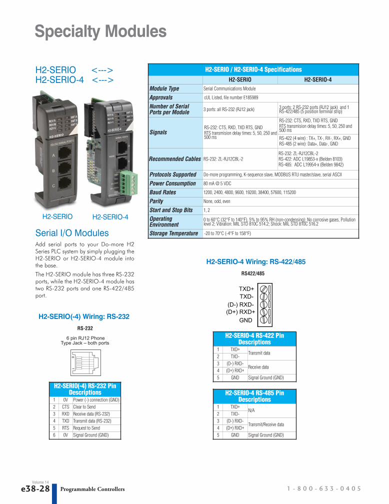
H2-SERIO <--->H2-SERIO-4 <--->
Serial I/O Modules Add serial ports to your Do-more H2Series PLC system by simply plugging theH2-SERIO or H2-SERIO-4 module intothe base.
The H2-SERIO module has three RS-232ports, while the H2-SERIO-4 module hastwo RS-232 ports and one RS-422/485port.
H2-SERIO / H2-SERIO-4 SpecificationsH2-SERIO H2-SERIO-4
Module Type Serial Communications Module
Approvals cUL Listed, file number E185989
Number of SerialPorts per Module 3 ports: all RS-232 (RJ12 jack) 3 ports: 2 RS-232 ports (RJ12 jack) and 1
RS-422/485 (5 position terminal strip)
SignalsRS-232: CTS, RXD, TXD RTS, GNDRTS transmision delay times: 5, 50, 250 and500 ms
RS-232: CTS, RXD, TXD RTS, GNDRTS transmision delay times: 5, 50, 250 and500 ms
RS-422 (4 wire) : TX+, TX-, RX-, RX+, GNDRS-485 (2 wire): Data+, Data-, GND
Recommended Cables RS-232: ZL-RJ12CBL-2RS-232: ZL-RJ12CBL-2RS-422: ADC L19853-x (Belden 8103)RS-485: ADC L19954-x (Belden 9842)
Protocols Supported Do-more programming, K-sequence slave, MODBUS RTU master/slave, serial ASCII
Power Consumption 80 mA @ 5 VDC
Baud Rates 1200, 2400, 4800, 9600, 19200, 38400, 57600, 115200
Parity None, odd, even
Start and Stop Bits 1, 2
OperatingEnvironment
0 to 60°C (32°F to 140°F), 5% to 95% RH (non-condensing); No corrosive gases, Pollutionlevel 2; Vibration: MIL STD 810C 514.2; Shock: MIL STD 810C 516.2
Storage Temperature -20 to 70°C (-4°F to 158°F)
H2-SERIO(-4) Wiring: RS-232
H2-SERIO(-4) RS-232 PinDescriptions
1 0V Power (-) connection (GND)2 CTS Clear to Send3 RXD Receive data (RS-232)4 TXD Transmit data (RS-232)5 RTS Request to Send6 0V Signal Ground (GND)
RS-232
16
6 pin RJ12 PhoneType Jack – both ports
Volume 14
H2-SERIO H2-SERIO-4
H2-SERIO-4 Wiring: RS-422/485
H2-SERIO-4 RS-422 PinDescriptions
1 TXD+Transmit data
2 TXD-3 (D-) RXD-
Receive data 4 (D+) RXD+
5 GND Signal Ground (GND)
RS422/485
GND
TXD+TXD-
(D-) RXD-(D+) RXD+
H2-SERIO-4 RS-485 PinDescriptions
1 TXD+N/A
2 TXD-3 (D-) RXD-
Transmit/Receive data 4 (D+) RXD+
5 GND Signal Ground (GND)

w w w . a u t o m a t i o n d i r e c t . c o m Programmable Controllers e38-29
CompanyInformation
SystemsOverview
ProgrammableControllers
Field I/O
Software
C-more & other HMI
Drives
SoftStarters
Motors &Gearbox
Steppers/Servos
Motor Controls
ProximitySensors
Photo Sensors
Limit Switches
Encoders
CurrentSensors
PressureSensors
TemperatureSensors
Pushbuttons/Lights
Process
Relays/Timers
Comm.
TerminalBlocks & Wiring
Power
CircuitProtection
Enclosures
Tools
Pneumatics
Appendix
ProductIndex
Part #Index
Volume 14
Specialty Modules
H2-ERM <--->
OverviewThe Ethernet Remote Master H2-ERMconnects a Do-more H2 Series PLC’slocal CPU base to slave I/O over a high-speed Ethernet link.
Need a lot of I/O?Each ERM module can support up to 16additional H2-EBC systems, 16Terminator I/O EBC systems, or 16 fullyexpanded H4-EBC systems. Of course,combinations are fine, too. The ERM alsosupports Edrives. See the Drives sectionfor details.Note: Applications requiring an extremelylarge number of T1H-EBC100 analog I/O orH4-EBC 16-channel analog I/O, couldexceed the buffer capacity of a singleH2-ERM module. In these cases, anadditional H2-ERM may be required.
Simple connectionsThe ERM connects to your controlnetwork using Category 5 UTP cables forcable runs up to 100 meters. Userepeaters to extend distances and expandthe number of nodes.
The PLC, ERM and EBC slave moduleswork together to update the remote I/Opoints. These three scan cycles are occur-ring at the same time, but asynchro-nously. Critical I/O points that must bemonitored every scan are best placed inthe CPU base.
Networking ERMs withother Ethernet devicesIt is highly recommended that a dedi-cated Ethernet remote I/O network beused for the ERM and its slaves. WhileEthernet networks can handle a largenumber of data transactions, andnormally handle them very quickly, heavyEthernet traffic can adversely affect thereliability of the slave I/O and the speedof the I/O network. Ensure ERM networks,multiple ERM networks and ECOM/officenetworks are isolated from one another.
Software configurationERM Workbench is a software utility thatmust be used to configure the ERM andits remote Ethernet slaves. ERM work-bench supports two methods of config-uring the ERM I/O network:
• ERM Workbench PLC Wizard greatly simplifies the configuration procedurewhen a PLC is used as the CPU interface.
• ERM Workbench configures the I/O network whether the CPU interface is aPLC or WinPLC, and allows access to allERM I/O network parameters.
ERM Workbench Software
Specifications H2-ERM
Communications 10BaseT Ethernet
Data Transfer Rate 10Mbps
Link Distance 100 meters(328 ft)
Ethernet Port RJ45
Ethernet Protocols TCP/IP, IPX
Power Consumption 320mA @5VDC
H2-ERM
Do-more CPU
H2-EBC100remote I/O
H4-EBCremote I/O
T1H-EBC100remote I/O
GS-EDRV100
GS3 drive
StrideEthernetSwitch
PC running ERM Workbench to configure the ERM andits slaves.The PC may be removed once the system isconfigured.
Stride Ethernet Switch (see the Communications
Products section for details)
Up to 100msegmentsbetweenswitches
H2-ERM

1 - 8 0 0 - 6 3 3 - 0 4 0 5e38-30 Programmable ControllersVolume 14
H2-EBC100 <--->
Use EBCs for Ethernet remote I/O slavesThe H2-EBC100 Ethernet Base Controllermodule provides a low-cost, high-perfor-mance Ethernet link for the Do-more H2Series PLC using the H2-ERM module andEthernet remote I/O. The H2-EBC100supports industry standard 10/100BaseTEthernet communications and is compat-ible with TCP/IP, IPX and Modbus TCP/IPprotocols for flexible PC communications.
Specialty Modules
Specifications H2-EBC100Communications 10/100Base-T Ethernet
Data Transfer Rate 100 Mbps max.
Link Distance 100 meters (328 ft)
Ethernet Port / Protocols
RJ45, TCP/IP, IPX, Modbus TCP/IP,DHCP, HTML configuration
Serial Port / Protocols RJ12, K-Sequence, ASCII IN/OUTModbus RTU
Power Consumption 300 mA
Easy to use, reliable and fastThe H2-EBC100 module plugs into theCPU slot of any DL205 I/O base andsupports all DL205 discrete and analogI/O modules. All EBC modules can beconfigured using NetEdit 3, included inthe free Do-more Designer software. TheH2-EBC100 also supports HTML config-uration.
H2-EBC100
NetEdit 3 Configuration Software
Do-more H2 Series PLC
H2-DM1E
H2-ERM
StrideEthernetSwitch
H2-EBC100
H2-EBC100
Up to 16 Ethernet remoteI/O bases
H2-EBC100

w w w . a u t o m a t i o n d i r e c t . c o m / P A C s Programmable Controllers e38-31
CompanyInformation
SystemsOverview
ProgrammableControllers
Field I/O
Software
C-more & other HMI
Drives
SoftStarters
Motors &Gearbox
Steppers/Servos
Motor Controls
ProximitySensors
Photo Sensors
Limit Switches
Encoders
CurrentSensors
PressureSensors
TemperatureSensors
Pushbuttons/Lights
Process
Relays/Timers
Comm.
TerminalBlocks & Wiring
Power
CircuitProtection
Enclosures
Tools
Pneumatics
Appendix
ProductIndex
Part #Index
Volume 14
Specialty Modules
H2-CTRIO <--->H2-CTRIO2 <--->
OverviewThe H2-CTRIO and H2-CTRIO2Counter I/O modules are designed toaccept high-speed pulse input signals forcounting or timing applications. Thesemodules also provide high-speed pulseoutput signals for servo/stepper motorcontrol, monitoring and alarming as wellas other discrete control functions.
The CTRIO(2) module offers greater flex-ibility for applications which call forprecise counting or timing based oninput events or for high speed controloutput applications. It can also be usedfor applications that call for a combina-tion of both high-speed input and high-speed output control functions.
The CTRIO(2) module has its own micro-processor and operates asynchronouslywith respect to the CPU. Therefore, theresponse time of the on-board outputs isbased on the module’s scan time, not theCPU’s scan time.
General SpecificationsSpecifications H2-CTRIO H2-CTRIO2
Discrete I/O Points Used None (I/O map directly in H2-DM1/E data structure)
Base Power Required 400 mA Max 275 mA Max
Isolation 2500V I/O to Logic, 1000V among InputChannels and All Outputs
1500V I/O to Logic, 1000V among InputChannels and All Outputs
Input SpecificationsSpecifications H2-CTRIO H2-CTRIO2
Inputs 8 pts sink/source
Maximum Input Frequency 100 kHz 250 kHz
Minimum Pulse Width 5 µsec 0.5 µsec
Input Voltage Range 9-30 VDC 9-30 VDC
Maximum Voltage 30 VDC
Input Voltage Protection Zener Clamped at 33 VDC
Rated Input Current 8 mA typical 12 mA maximum
Minimum ON Voltage 9.0 VDC
Maximum OFF Voltage 2.0 VDC
Minimum ON Current 5.0 mA
Maximum OFF Current 2.0 mA
OFF to ON Response Less than 3 µsec Less than 0.5 µsec
ON to OFF Response Less than 3 µsec Less than 0.5 µsec
Output SpecificationsSpecifications H2-CTRIO H2-CTRIO2
Outputs 4 pts (sink/source), independently isolated
Pulse Outputs 2 channels, 20 Hz to 25 kHzPulse/Direction or CW/CCW
2 channels, 20 Hz to 250 kHzPulse/Direction or CW/CCW
Minimum Pulse Width 5 µsec 0.5 µsecOutput Voltage Range 5-36 VDCMaximum Output Voltage 36 VDC
Maximum Load Current 1.0 A 1.0 A at 23°C0.5 A at 60°C
Maximum Leakage Current 100 µA Inrush Current 5.0 A for 20 ms 2.0 A for 10 msON State V Drop 0.3 VDC or less 0.45 VDC or lessOvercurrent Protection YesOFF to ON Response less than 3 µsec less than 1 µsecON to OFF Response less than 3 µsec less than 1 µsec
Software ConfigurationAll scaling and configuration is done fromwithin the Edit CTRIO/CTRIO2Configuration window of Do-moreDesigner. This eliminates the need for PLCladder programming or other interfacedevice programming to configure themodule.
Edit CTRIO/CTRIO2 Configuration Window Inputs Supported:• Counter• Quad Counter• Pulse Catch• Edge Timer• Dual Edge Timer
Outputs Supported:• Pulse train - used for servo/stepper
motor control. Configurable forCW/CCW or step and direction
• Discrete outputs - assigned toCounter/Timer input functions
• Raw output - outputs controlleddirectly from the CPU interface program
• Programmable limit switch
H2-CTRIO2H2-CTRIO

1 - 8 0 0 - 6 3 3 - 0 4 0 5e38-32 Programmable ControllersVolume 14
Specialty Modules
F2-08SIM <--->F2-08SIM Input Simulator
Inputs per Module 8Base Power Required 5VDC 50 mATerminal Type NoneStatus Indicator Switch sideWeight 2.65 oz. (75 g)
F2-08SIM

1 - 8 0 0 - 6 3 3 - 0 4 0 5e38-4 Programmable ControllersVolume 14
Do-more H2 Series PLC Overview
Module CompatibilityThe following table shows which DL205 components are supported by the H2-DM1 andH2-DM1E Do-more CPUs.
= Supported No = Not Supported
Module Compatibility TableModule Part Number Status Module Part Number Status
Base Units
D2-03B-1
Analog I/OModules
F2-04AD-1
D2-04B-1 F2-04AD-2
D2-06B-1 F2-08AD-1
D2-09B-1 F2-08AD-2
D2-03BDC1-1 F2-04RTD
D2-04BDC1-1 F2-04THM
D2-06BDC1-1 F2-02DA-1(L)
D2-09BDC1-1 F2-02DA-2(L)
D2-06BDC2-1 F2-02DAS-1
D2-09BDC2-1 F2-02DAS-2
Discrete I/O Modules
D2-08ND3 F2-08DA-1
D2-16ND3-2 F2-08DA-2
D2-32ND3 F2-4AD2DA
D2-32ND3-2 F2-8AD4DA-1
D2-08NA-1 F2-8AD4DA-2
D2-08NA-2 Local ExpansionModules
D2-CM No
D2-16NA D2-EM No
D2-04TD1
SpecialtyModules
H2-ERM
D2-08TD1 H2-ERM-F
D2-08TD2 D2-RMSM No
D2-16TD1-2 D2-RSSS No
D2-16TD2-2 H2-ECOM100
F2-16TD1P H2-ECOM-F
F2-16TD2P D2-DCM No
D2-32TD1 H2-EBC100
D2-32TD2 H2-EBC-F
D2-08TA H2-SERIO
F2-08TA H2-SERIO-4
D2-12TA F2-CP128 No
D2-04TRS H2-CTRIO
D2-08TR H2-CTRIO2
F2-08TR D2-CTRINT No
F2-08TRS F2-08SIM
D2-12TR Programmer D2-HPP No
D2-08CDROperatorInterface DV-1000 No
w w w . a u t o m a t i o n d i r e c t . c o m / P A C s Programmable Controllers e38-5
CompanyInformation
SystemsOverview
ProgrammableControllers
Field I/O
Software
C-more & other HMI
Drives
SoftStarters
Motors &Gearbox
Steppers/Servos
Motor Controls
ProximitySensors
Photo Sensors
Limit Switches
Encoders
CurrentSensors
PressureSensors
TemperatureSensors
Pushbuttons/Lights
Process
Relays/Timers
Comm.
TerminalBlocks & Wiring
Power
CircuitProtection
Enclosures
Tools
Pneumatics
Appendix
ProductIndex
Part #Index
Volume 14
Do-more H2 Series PLC Overview
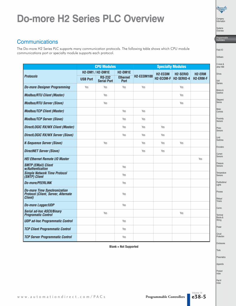
CPU Modules Specialty Modules
ProtocolsH2-DM1 / H2-DM1E H2-DM1E
H2-ECOM100 H2-ECOMH2-ECOM-F
H2-SERIOH2-SERIO-4
H2-ERM H2-ERM-FUSB Port RS-232
Serial PortEthernet
Port
Do-more Designer Programming Yes Yes Yes Yes Yes
Modbus/RTU Client (Master) Yes Yes
Modbus/RTU Server (Slave) Yes Yes
Modbus/TCP Client (Master) Yes Yes
Modbus/TCP Server (Slave) Yes Yes
DirectLOGIC RX/WX Client (Master) Yes Yes Yes
DirectLOGIC RX/WX Server (Slave) Yes Yes Yes
K-Sequence Server (Slave) Yes Yes Yes Yes
DirectNET Server (Slave) Yes Yes
HEI Ethernet Remote I/O Master Yes
SMTP (EMail) Clientw/Authentication Yes
Simple Network Time Protocol(SNTP) Client Yes
Do-more/PEERLINK Yes
Do-more Time SynchronizationProtocol (Client, Server, AlternateClient)
Yes
Do-more Logger/UDP Yes
Serial ad-hoc ASCII/BinaryProgramatic Control Yes Yes
UDP ad-hoc Programmatic Control Yes
TCP Client Programmatic Control Yes
TCP Server Programmatic Control Yes
CommunicationsThe Do-more H2 Series PLC supports many communication protocols. The following table shows which CPU modulecommunications port or specialty module supports each protocol.
Blank = Not Supported

1 - 8 0 0 - 6 3 3 - 0 4 0 5e38-34 Programmable ControllersVolume 14
Wiring Solutions
Wiring Solutions using the ZIPLink Wiring System
Solution 1: Do-more H2 Series PLC to ZIPLinkConnector ModulesWhen looking for quick and easy I/O-to-field termination, a ZIPLinkconnector module used in conjunction with a prewired ZIPLink cable,consisting of an I/O terminal block at one end and a multi-pinconnector at the other end, is the best solution.
Using the PLC I/O Modules to ZIPLink ConnectorModules selector tables located in this section,
1. Locate your I/O module/PLC. 2. Select a ZIPLink Module. 3. Select a corresponding ZIPLink Cable.
Solution 3: GS Series and DuraPulse DrivesCommunication CablesNeed to communicate via Modbus RTU to a drive or anetwork of drives?
ZIPLink cables are available in a wide range of configurations for connecting to PLCs and SureServo,SureStep, Stellar Soft Starter and AC drives. Add a ZIPLinkcommunications module to quickly and easily set up amulti-device network.
Using the Drives Communication selector tables located inthis section,
1. Locate your Drive and type of commu-nications. 2. Select a ZIPLink cable and other associ-ated hardware.
Solution 2: Do-more H2 Series PLC to 3rd PartyDevicesWhen wanting to connect I/O to another device within close proximityof the I/O modules, no extra terminal blocks are necessary when usingthe ZIPLink Pigtail Cables. ZIPLink Pigtail Cables are prewired to an I/Oterminal block with color-coded pigtail with soldered-tip wires on theother end.
Using the I/O Modules to 3rd Party Devices selector tableslocated in this section,
1. Locate your PLC I/O module. 2. Select a ZIPLink Pigtail Cable that is compatible
with your 3rd party device.
ZIPLinks simplify the normally tedious process of wiring betweendevices by utilizing prewired cables and DIN rail mountconnector modules. It's as simple as plugging in a cableconnector at either end or terminating wires at only one end.Prewired cables keep installation clean and efficient, using halfthe space at a fraction of the cost of standard terminal blocks.There are several wiring solutions available when using theZIPLink System ranging from PLC I/O-to-ZIPLink Connector
Modules that are ready for field termination, options forconnecting to third party devices, GS, DuraPulse and SureServoDrives, and specialty relay, transorb and communicationsmodules. Pre-printed I/O-specific adhesive label strips for quickmarking of ZIPLink modules are provided with ZIPLink cables.See the following solutions to help determine the best ZIPLinksystem for your application.

w w w . a u t o m a t i o n d i r e c t . c o m / P A C s Programmable Controllers e38-35
CompanyInformation
SystemsOverview
ProgrammableControllers
Field I/O
Software
C-more & other HMI
Drives
SoftStarters
Motors &Gearbox
Steppers/Servos
Motor Controls
ProximitySensors
Photo Sensors
Limit Switches
Encoders
CurrentSensors
PressureSensors
TemperatureSensors
Pushbuttons/Lights
Process
Relays/Timers
Comm.
TerminalBlocks & Wiring
Power
CircuitProtection
Enclosures
Tools
Pneumatics
Appendix
ProductIndex
Part #Index
Volume 14
Wiring Solutions
Solution 4: Serial Communications CablesZIPLink offers communications cables for use with Do-more H2 SeriesCPUs, that can also be used with other communications devices.Connections include a 6-pin RJ12 or 9-pin, 15-pin and 25-pin D-subconnectors which can be used in conjunction with the RJ12 or D-SubFeedthrough modules.
Using the Serial Communications Cables selectortable located in this section,
1. Locate your connector type 2. Select a cable.
Solution 5: Specialty ZIPLink ModulesFor additional application solutions, ZIPLink modules are available in avariety of configurations including stand-alone relays, 24VDC and120VAC transorb modules, D-sub and RJ12 feedthrough modules,communication port adapter and distribution modules, and SureServo50-pin I/O interface connection.
Using the ZIPLink Specialty Modules selector tablelocated in this section,
1. Locate the type of application. 2. Select a ZIPLink module.
Solution 6: ZIPLink Connector Modules to 3rd PartyDevicesIf you need a way to connect your device to terminal blocks withoutall that wiring time, then our pigtail cables with color-codedsoldered-tip wires are a good solution. Used in conjunction with anycompatible ZIPLink Connector Modules, a pigtail cable keeps wiringclean and easy and reduces troubleshooting time.
Using the Universal Connector Modules and PigtailCables table located in this section,
1. Select module type.2. Select the number of pins.3. Select cable.

1 - 8 0 0 - 6 3 3 - 0 4 0 5e38-36 Programmable ControllersVolume 14
NOTE: ZIPLINK CONNECTOR MODULES AND ZIPLINK CABLES SPECI-FICATIONS ARE IN THE ZIPLINK CATALOG SECTION.
Wiring Solutions
Do-more PLC Input Module ZIPLink SelectorPLC ZIPLink
InputModule
# ofTerms Component Module Cable †
D2-08ND3 10 Feedthrough ZL-RTB20 ZL-D2-CBL10*
D2-16ND3-2 19Feedthrough ZL-RTB20 ZL-D2-CBL19*
Sensor ZL-LTB16-24 ZL-D2-CBL19*
D2-32ND3¹ 40
Feedthrough ZL-RTB40ZL-D24-CBL40*
ZL-D24-CBL40*X
Sensor ZL-LTB32-24ZL-D24-CBL40*
ZL-D24-CBL40*X
D2-32ND3-2¹ 40
Feedthrough ZL-RTB40ZL-D24-CBL40*
ZL-D24-CBL40*X
Sensor ZL-LTB32-24ZL-D24-CBL40*
ZL-D24-CBL40*X
D2-08NA-1 10 Feedthrough ZL-RTB20 ZL-D2-CBL10*
D2-08NA-2 10 Feedthrough ZL-RTB20 ZL-D2-CBL10*
D2-16NA 19 Feedthrough ZL-RTB20 ZL-D2-CBL19*
Do-more PLC Analog Module ZIPLink SelectorPLC ZIPLink
AnalogModule
# ofTerms Component Module Cable
F2-04AD-1 10 Feedthrough ZL-RTB20 ZL-D2-CBL10*F2-08AD-1 10 Feedthrough ZL-RTB20 ZL-D2-CBL10*F2-04AD-2 10 Feedthrough ZL-RTB20 ZL-D2-CBL10*F2-08AD-2 10 Feedthrough ZL-RTB20 ZL-D2-CBL10*F2-02DA-1 10 Feedthrough ZL-RTB20 ZL-D2-CBL10*F2-02DA-1L 10 Feedthrough ZL-RTB20 ZL-D2-CBL10*F2-02DAS-1 10 Feedthrough ZL-RTB20 ZL-D2-CBL10*F2-08DA-1 19 Feedthrough ZL-RTB20 ZL-D2-CBL19*F2-02DA-2 10 Feedthrough ZL-RTB20 ZL-D2-CBL10*F2-02DA-2L 10 Feedthrough ZL-RTB20 ZL-D2-CBL10*F2-02DAS-2 10 Feedthrough ZL-RTB20 ZL-D2-CBL10*F2-08DA-2 10 Feedthrough ZL-RTB20 ZL-D2-CBL10*F2-4AD2DA 10 Feedthrough ZL-RTB20 ZL-D2-CBL10*F2-8AD4DA-1 19 Feedthrough ZL-RTB20 ZL-D2-CBL19*F2-8AD4DA-2 19 Feedthrough ZL-RTB20 ZL-D2-CBL19*
F2-04RTD2 MatchedOnly See Note 2
F2-04THM2 MatchedOnly See Note 2
Do-more PLC Combo In/Out Module ZIPLink Selector
PLC ZIPLinkComboModule
# ofTerms Component Module Cable
D2-08CDR 10 Feedthrough ZL-RTB20 ZL-D2-CBL10*
Do-more PLC Output Module ZIPLink SelectorPLC ZIPLink
OutputModule # of Terms Component Module Cable †
D2-04TD1³ 10 Feedthrough ZL-RTB20 ZL-D2-CBL10*
D2-08TD1 10 Feedthrough ZL-RTB20 ZL-D2-CBL10*D2-08TD2 10 Feedthrough ZL-RTB20 ZL-D2-CBL10*
D2-16TD1-2 19
Feedthrough ZL-RTB20 ZL-D2-CBL19*
Fuse ZL-RFU205 ZL-D2-CBL19*
Relay ZL-RRL16-24-1 ZL-D2-CBL19*
D2-16TD2-2 19Feedthrough ZL-RTB20 ZL-D2-CBL19*Fuse ZL-RFU205 ZL-D2-CBL19*Relay ZL-RRL16-24-2 ZL-D2-CBL19*
F2-16TD1P 19Feedthrough ZL-RTB20 ZL-D2-CBL19*Relay ZL-RRL16-24-1 ZL-D2-CBL19*
F2-16TD2P 19Feedthrough ZL-RTB20 ZL-D2-CBL19*Relay ZL-RRL16-24-2 ZL-D2-CBL19*
D2-32TD1¹ 40Feedthrough ZL-RTB40
ZL-D24-CBL40*
ZL-D24-CBL40*X
Fuse ZL-RFU405 ZL-D24-CBL40*ZL-D24-CBL40*X
D2-32TD2¹ 40Feedthrough ZL-RTB40
ZL-D24-CBL40*ZL-D24-CBL40*X
Fuse ZL-RFU405 ZL-D24-CBL40*ZL-D24-CBL40*X
D2-08TA 10 Feedthrough ZL-RTB20 ZL-D2-CBL10*F2-08TA 10 Feedthrough ZL-RTB20 ZL-D2-CBL10*
D2-12TA 19Feedthrough ZL-RTB20 ZL-D2-CBL19*
Fuse ZL-RFU205 ZL-D2-CBL19*
D2-04TRS³ 10 Feedthrough ZL-RTB20 ZL-D2-CBL10*
D2-08TR 10 Feedthrough ZL-RTB20 ZL-D2-CBL10*
F2-08TRS³ 19 Feedthrough ZL-RTB20 ZL-D2-CBL19*
F2-08TR4 10 Feedthrough ZL-RTB20 ZL-D2-CBL10*
D2-12TR 19Feedthrough ZL-RTB20 ZL-D2-CBL19*
Fuse ZL-RFU205 ZL-D2-CBL19*
† X in the part number represents a 45° angle plug
* Select the cable length by replacing the * with: Blank = 0.5m, -1 = 1.0m, or -2 =2.0m.
1 To make a custom cable for the 32-point modules, use: Ribbon-style Connector ZL-D24-CON-R, Solder-style 180° connector ZL-D24-CON or Solder-style 45° connectorZL-D24-CON-X.
2 The F2-04RTD and F2-04THM modules are not supported by the ZIPLink wiring sys-tem.
3 Caution: The D2-04TD1, D2-04TRS, and F2-08TRS outputs are derated not to exceedmodule specs 2A per point and 2A per common when used with the ZIPLink wiringsystem.
4 The F2-08TR outputs are derated not to exceed 2A per point and 4A per commonwhen used with the ZIPLink wiring system.
5 Note: Fuses (5 x 20 mm) are not included. See Edison Electronic Fuse section for (5 x20 mm) fuse. S500 and GMA electronic circuit protection for fast-acting maximumprotection. S506 and GMC electronic circuit protection for time-delay performance.Ideal for inductive circuits.To ensure proper operation, do not exceed the voltage andcurrent rating of ZIPLink module. ZL-RFU20 = 2A per circuit; ZL-RFU40 = 400 mA percircuit.

1 - 8 0 0 - 6 3 3 - 0 4 0 5e38-20 Programmable ControllersVolume 14
Power BudgetWhen determining the types and quantityof I/O modules you will be using, it isimportant to remember there is a definedamount of power available from the basepower supply.
The chart on the next page indicates thepower supplied and used by eachmodule. The adjacent chart shows anexample of how to calculate the powerused by your particular system. Thesecharts should make it easy for you todetermine if the devices you have chosenwill operate within the power budget ofyour system configuration.
If the I/O you have chosen for a baseexceeds the maximum power availablefrom the power supply, you may be ableto resolve the problem by using remoteI/O bases.
Base power supply specificationsThe table below lists base power supplyspecifications, including maximum inrushcurrent and maximum power consumedfrom your power source.
Power budget exampleThe example on the right shows how tocalculate the power budget for the Do-more PLC system. The examples areconstructed around a single 9-slot baseusing the devices shown. It is recom-mended you construct a similar table foryour Do-more PLC system. Follow thesteps to the right to determine your powerbudget.
1.Using a chart similar to the one below,fill in column 2.
2.Using the tables on the next page, enterthe current supplied and used by eachdevice (columns 3 and 4). Deviceswhich fall into the "Other" category(Row D) are devices such as the oper-ator interface and the handheldprogrammer, which also have powerrequirements, but do not directly pluginto the base.
3.Add the current used by the systemdevices (columns 3 and 4) starting withthe CPU slot and put the total in therow labeled “Maximum CurrentRequired” (Row E).
4.Subtract the row labeled “MaximumCurrent Required” (Row E), from therow labeled “Current Supplied” (RowB). Place the difference in the rowlabeled “Remaining Current Available”(Row F).
5.If “Maximum Current Required” isgreater than “Current Supplied” ineither column 3 or 4, the power budgetwill be exceeded. It will be unsafe touse this configuration, and you willneed to restructure your I/O configura-tion. Note the auxiliary power supplydoes not need to supply all the externalpower. If you need more than the300mA supplied, you can add anexternal 24V power supply. This willhelp keep you within your powerbudget for external power.
A Column 1 Column 2 Column 3 Column 4
Device Type 5VDC (mA) External Power 24VDC (mA)
B CURRENT SUPPLIED
Base 9 slot 2,600 300
C CURRENT REQUIRED
CPU SLOTSLOT 0SLOT 1SLOT 2SLOT 3SLOT 4SLOT 5SLOT 6SLOT 7
H2-DM1ED2-16ND3-2D2-16ND3-2D2-16NAD2-08NA-1D2-16TD1-2D2-08TAD2-08TA
27510010010050200250250
000008000
D OTHER
Operator interface EA1-S3ML 90 0
E Maximum Current Required 1415 80
F Remaining Current Available 2600-1415=1185 300-80=220
Power Supply Specifications
Specification AC Powered Bases 24 VDC Powered Bases 125 VDC Powered Bases
Part Numbers D2-03B-1, D2-04B-1, D2-06B-1, D2-09B-1 D2-03BDC1-1, D2-04BDC1-1, D2-06BDC1-1, D2-09BDC1-1 D2-06BDC2-1, D2-09BDC2-1
Voltage Withstand (dielectric) 1 minute @ 1,500 VAC between primary, secondary, field ground, and run relay
Insulation Resistance > 10 M� at 500 VDC
Input Voltage Range85-132 VAC (110 range) 170-264 VAC ( 220 range) 47-63 Hz
10.2-28.8 VDC (24 VDC)with less than 10% ripple
100-264 VDC (125 VDC) with less than 10% ripple
Auxiliary 24 VDC Output 300 mA max. none 300 mA max.
Maximum Inrush Current 30A 10A 20A
Maximum Power 80 VA 25W 30W
Base Units

w w w . a u t o m a t i o n d i r e c t . c o m / P A C s Programmable Controllers e38-21
CompanyInformation
SystemsOverview
ProgrammableControllers
Field I/O
Software
C-more & other HMI
Drives
SoftStarters
Motors &Gearbox
Steppers/Servos
Motor Controls
ProximitySensors
Photo Sensors
Limit Switches
Encoders
CurrentSensors
PressureSensors
TemperatureSensors
Pushbuttons/Lights
Process
Relays/Timers
Comm.
TerminalBlocks & Wiring
Power
CircuitProtection
Enclosures
Tools
Pneumatics
Appendix
ProductIndex
Part #Index
Volume 14
Base Units
Power RequirementsThis section shows the amount of powersupplied by each of the base powersupplies and the amount of powerconsumed by each module. The PowerConsumed charts list how muchINTERNAL power from each power sourceis required for the modules. Use this infor-mation when calculating the powerbudget for your system.
In addition to the internal power sources,bases offer a 24 VDC auxiliary powersupply with external power connections.This auxiliary power supply can powerexternal devices.
Use ZipLinks to reduce powerrequirementsIf your application requires a lot of relayoutputs, consider using the ZIPLink AC orDC relay output modules ZL-RRL16-24-1or ZL-RRL16-24-2. These modules canswitch high current (10A) loads withoutputting a heavy load on your base powerbudget. Refer to the Terminal Blocks andWiring Solutions section in this catalog formore information.
This logo is placed next to the I/Omodules that are supported by the ZIPLinkconnection systems. See the I/O modulespecifications at the end ofthis section.
Power ConsumedDevice 5V(mA) 24V AuxiliaryCPUsH2-DM1 250 0
H2-DM1E 275 0
DC Input ModulesD2-08ND3 50 0
D2-16ND3-2 100 0
D2-32ND3 25 0
D2-32ND3-2 25 0
AC Input ModulesD2-08NA-1 50 0
D2-08NA-2 100 0
D2-16NA 100 0
DC Output ModulesD2-04TD1 60 20
D2-08TD1 100 0
D2-08TD2 100 0
D2-16TD1-2 200 80
D2-16TD2-2 200 0
F2-16TD1P 70 50
F2-16TD2P 70 50
D2-32TD1 350 0
D2-32TD2 350 0
AC Output ModulesD2-08TA 250 0
F2-08TA 250 0
D2-12TA 350 0
Relay Output ModulesD2-04TRS 250 0
D2-08TR 250 0
F2-08TR 670 0
F2-08TRS 670 0
D2-12TR 450 0
Combination In/Out ModuleD2-08CDR 200 0
Power ConsumedDevice 5V(mA) 24V AuxiliaryAnalog ModulesF2-04AD-1 100 5
F2-04AD-2 110 5
F2-08AD-1 100 5
F2-08AD-2 100 5
F2-02DA-1 40 60 (note 1)
F2-02DA-1L 40 70 @ 12V (note 1)
F2-02DA-2 40 60
F2-02DA-2L 40 70 @ 12V
F2-02DAS-1 100 50 / channel
F2-02DAS-2 100 60 / channel
F2-08DA-1 30 50 (note 1)
F2-08DA-2 60 140
F2-4AD2DA 60 80 (note 1)
F2-8AD4DA-1 35 100 (note 1)
F2-8AD4DA-2 35 80 (note 1)
F2-04RTD 90 0
F2-04THM 110 60
Specialty ModulesH2-CTRIO 400 0
H2-CTRIO2 275 0
H2-EBC100 300 0
H2-ECOM100 300 0
H2-ERM 320 0
H2-SERIO 80 0
H2-SERIO-4 80 0
F2-08SIM 50 0Note 1: Add an additional 20 mA per output loop.
Power SuppliedDevice 5V(mA) 24V Auxiliary Device 5V(mA) 24V AuxiliaryBases BasesD2-03B-1 2600 300 D2-04BDC1-1 2600 None
D2-04B-1 2600 300 D2-06BDC1-1 2600 None
D2-06B-1 2600 300 D2-09BDC1-1 2600 None
D2-09B-1 2600 300 D2-06BDC2-1 2600 300
D2-03BDC1-1 2600 None D2-09BDC2-1 2600 300