LONESTARDRILLS.COM littlebeaver.com sales@littlebeaverLS400 Hydraulic Water Well Drilling Rig...
26
LS400 Hydraulic Water Well Drilling Rig OPERATOR’S MANUAL littlebeaver.com [email protected] P.O. Box 840, Livingston, Texas 77351 Phone: 936.327.3121 Fax: 936.327.4025 MFG BY: Little Beaver, Inc. 1017 1.800.227.7515 LONESTARDRILLS.COM
Transcript of LONESTARDRILLS.COM littlebeaver.com sales@littlebeaverLS400 Hydraulic Water Well Drilling Rig...

LS400
Hydraulic Water Well Drilling Rig
OPERATOR’S MANUAL
littlebeaver.com [email protected] P.O. Box 840, Livingston, Texas 77351
Phone: 936.327.3121 Fax: 936.327.4025MFG BY: Little Beaver, Inc. 1017
1.800.227.7515LONESTARDRILLS.COM

1017Page O-2
CUSTOMER SERVICEPh: 800/227-7515 or 936/327-3121 or Fax 936/327-4025
ORDERS...Place your orders by telephone, fax, or mail. When calling, please have your parts manual handyfor reference. Our hours are 8:00 am - 4:30 pm central time, Monday thru Friday. When orderingby mail or fax, include a description and LITTLE BEAVER part number for the items you areordering, your return address, and payment or your authorization for COD shipment.All orders are shipped UPS where possible. Freight charges will be added to your invoice. Someitems are oversize, resulting in a higher shipping cost. Power units and larger augers areshipped via motor freight due to their weight.
PAYMENT TERMS...COD, Cash in Advance, Visa, Mastercard or NET 30 with approved credit. COD limit for newaccounts is $500.00. Personal or company checks on new accounts will be held until they clearthe bank. To eliminate this delay, you may pay by wire transfer or send a certified or cashierscheck. For a NET 30 open account, please call or write for a credit application.
SERVICE AND REPAIR...Your Lone Star Hydraulic Water Well Drill Rig has been designed for user repair with ordinaryhand tools. No special tools are required. Consult the appropriate section of the parts manualfor instructions.
Service or technical consulation is available, free of charge, from the factory in Livingston, Texas.We will be pleased to help you with any problems or questions. Just write, fax, or call. Our hoursare 8:00am - 4:30pm central time, Monday thru Friday.
Factory repair is available. If you return a part to the factory, please include the followinginformation: Your name and return address, a description of the problem and payment orauthorization to return the repaired item COD for the repair and shipping charges.
RETURNS...Please call the factory for a return authorization. This will help to ensure that your parts arehandled properly. Include your name and address, customer account #, invoice # under whichthe returned parts were ordered, and a brief description of the problem with the parts or thereason for returning them. Parts to be considered for warranty must be returned to the factory forinspection within 10 days after receipt of replacement parts. Be sure to prepay the shippingcharges, we will not accept collect or COD packages.
Our mailing address...LITTLE BEAVER, Inc.P. O. Box 840Livingston, Texas 77351
The machine serial number for your Lone Star Hydraulic Water Well Rig is located on the rear side of
control panel as shown in figure 7. For your convenience, when requiring service or parts
information, refer to this number and your model number. Record the model number, machine serial
number and date of purchase in the space provided below:


medical treatment is not administered immediately.
CAUTION: Head protection must be worn at all times. Serious injury from falling objects may result.

MAINTENANCE AND LUBRICATION
CAUTION: Shut off power to adjust, service, or clean the machine.
CAUTION: Keep all safety shields and devices in place.
CAUTION: Do not climb mast to perform maintenance or lubricate. Climbing the mast
introduces a falling hazard which may cause injury to climber or persons on ground. Always
perform maintenance and lubrication procedures with mast in horizontal position.
CAUTION: Read and understand operator’s manual for each engine and mud pump.
Refer to operator’s manual of each engine and pump for maintenance information
WARNING: NEVER use hands to search for leaks, instead, use a piece of cardboard or wood.
Escaping hydraulic fluid under pressure can have sufficient force to penetrate the skin, causing
serious injury. Before disconnecting lines, be sure to relieve pressure. Before applying pressure,
be sure connections are tight and fittings and hoses are not damaged.
If injured by escaping fluid, see a doctor at once. Serious infection and/or reaction can develop
if proper medical treatment is not administered immediately.
HYDRAULIC OIL LEAKAGE: If any hydraulic oil leakage is encountered, check and
properly tighten the associated fitting. (Refer to torque chart for proper assembly torque). If the
leakage persists, it may be necessary to replace the associated fitting or hose assembly. If one of
the quick disconnect fittings is the source of leakage, the leaking quick disconnect fitting should
be replaced.
IMPORTANT: Keep all nuts, fasteners, and fittings properly torqued. Refer to Torque Chart
(inside back cover) for proper assembly torque.
RECOMMENDED GREASE: JET-PLEX-EP Lithium Complex Grease
Part no. 70794 for 14 oz. cartridge
NLGI No. 2 Grade
WEAR PLATES:
Lubrication:
The mast plate and wear plates should be kept clean and free of dirt and debris. Abrasives such
as sand, dust, and grit mixed with lubricant on plate surfaces causes accelerated wearing and
scoring of mast plate and wear plates. Therefore, clean mast plate surfaces by wiping surfaces
with clean rag. Daily lubricate (with paint brush) by applying a film of anti-seize compound
(KOPR-KOTE) on both sides of mast plate, front and rear, where wear plates slide. For best
results, apply anti-seize compound to mast plate while mast is in transport position. If anti-seize
compound is not available, tool joint compound may be used.

MAINTENANCE AND LUBRICATION CONT...
Adjustment:
Initially, the shim plates used to provide clearance between the 5/8” thick mast plate and wear
plates are two 5/16” and one 24 gauge (.024”) inch shim plates on each side (two ¼” shim plates
are also provided for future adjustment). Clearance between wear plates and mast plate should
be monitored for excessive clearance. As clearance approaches .060”, the 24 gauge shim plates
should be removed to decrease clearance. By using various combinations of shim plates,
clearance between wear plates and mast plate should be maintained between .024” and .060”.
Note: as wear plates wear, they may be flipped over and reassembled to decrease clearance.
Mast Plate
Tower Lift Support (disengaged position)
Draw-works
(Leaf) Chain
Shuttle Plate
Wear Plates
Shim Plates
Figure 1 (Folder: LS400_Manual) (LS400 Manual 016.JPG)

MAINTENANCE AND LUBRICATION CONT...
DRAW-WORKS (LEAF) CHAIN:
CAUTION: It is important to carefully inspect and maintain the chain. Failure of draw-works
chain due to excessive wear, damage, and corrosion may cause serious injury.
Adjustment: As chain stretches, it is important to maintain proper tension of chain. During
drilling process, observe chain slap against mast plate. Some chain slap is normal. However,
when chain slap becomes excessive, chain will require adjusting to remove excessive slack.
With the rotary head lowered and mast in transport position, adjust upper anchor bolt (located
behind draw-works cylinder) by loosening lock nut and tightening adjustment nut. Tighten nut
until chain slightly lifts off mast plate. It is important to not over tighten chain so some slack is
maintained. In other words, it is better to have a little too much slack than to over tighten chain.
The upper (longer) chain is subjected to greater loads than the lower (shorter) chain. Therefore,
the upper anchor bolt will require adjusting more frequently than lower anchor bolt (located at
base, rear of mast. NOTE: The bottom of shuttle plate (& wear plates) should come to between
½” to 1” from the bottom of mast plate. When chain can no longer be adjusted to maintain this
clearance, the chain must be replaced.
Adjustment Nut Lock Nut
Draw-works Cylinder
Upper
Anchor Bolt
Figure 2 (Folder: LS400_Manual) (LS400 Manual 053.JPG)
Periodic Inspection:
After each 30 days of operation (more frequently if exposed to rain and/or dust) leaf chains
should be inspected and lubricated. To aid in inspection and prior to lubrication, chains should
be cleaned. Water, steam, compressed air, and/or WD-40 may be used to clean chain. Carefully
examine chain and chain components for rust, corrosion, wear, and damage. Pay particular
attention to the sections of chain which moves over sheaves and to chain anchor points. Inspect
components for bending, damaged threads, cracked welds, or damaged retaining pins. Also, be
sure lock nuts and adjustment nuts remain tightened properly.
MAINTENANCE AND LUBRICATION CONT...
Lubrication:
Prior to lubrication, chains should be cleaned. Cleaning and lubrication may be more effective
by adjusting chain to increase slack or by removing chain to aid penetration between plates and
joints. Abrasives such as sand, dust, and grit mixed with oil on chain causes accelerated wearing
and scoring of articulating members of chain (pins and plates). Use water, steam, compressed
air, and/or WD-40 to clean chain with the aid of a stiff brush or wire brush. However, if water or
steam is used, compressed air or WD-40 must be used to remove moisture from chain plates and
joints. Use the heaviest (highest viscosity) oil that will penetrate plates and joints. Try #40 oil
and adjust for operating temperature for best results. Apply oil with paint brush or directly pour
on, but chain should be well flooded to ensure oil penetrates in between plates and into joints.
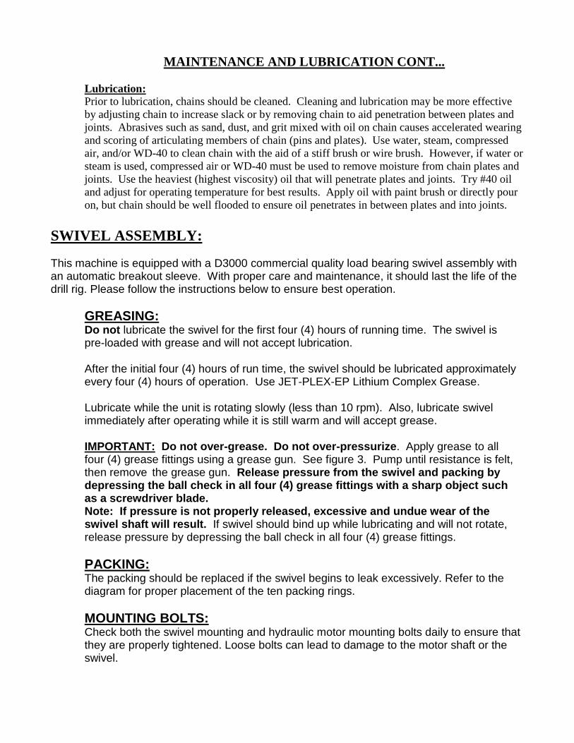
SWIVEL ASSEMBLY:
This machine is equipped with a D3000 commercial quality load bearing swivel assembly with an automatic breakout sleeve. With proper care and maintenance, it should last the life of the drill rig. Please follow the instructions below to ensure best operation.
GREASING: Do not lubricate the swivel for the first four (4) hours of running time. The swivel is pre-loaded with grease and will not accept lubrication.
After the initial four (4) hours of run time, the swivel should be lubricated approximately every four (4) hours of operation. Use JET-PLEX-EP Lithium Complex Grease.
Lubricate while the unit is rotating slowly (less than 10 rpm). Also, lubricate swivel immediately after operating while it is still warm and will accept grease.
IMPORTANT: Do not over-grease. Do not over-pressurize. Apply grease to all four (4) grease fittings using a grease gun. See figure 3. Pump until resistance is felt, then remove the grease gun. Release pressure from the swivel and packing by depressing the ball check in all four (4) grease fittings with a sharp object such as a screwdriver blade. Note: If pressure is not properly released, excessive and undue wear of the swivel shaft will result. If swivel should bind up while lubricating and will not rotate, release pressure by depressing the ball check in all four (4) grease fittings.
PACKING: The packing should be replaced if the swivel begins to leak excessively. Refer to thediagram for proper placement of the ten packing rings.
MOUNTING BOLTS: Check both the swivel mounting and hydraulic motor mounting bolts daily to ensure thatthey are properly tightened. Loose bolts can lead to damage to the motor shaft or theswivel.

MAINTENANCE AND LUBRICATION CONT...
Rotary Hydraulic Motor
Tower Lift Support
(engaged position)
Swivel Assembly
Grease Fittings
Figure 3 Rotary Drill Head Assembly (Folder: LS400_Manual) (LS400 Manual 018.JPG)
DRILL PIPE: Always lubricate the drill pipe threads with pipe joint compound before making up each
connection. After use, clean both male (pin) and female (box) threads with a wire brush to
remove dirt and grease residue. Replace the cap on the pin end. Clean all foreign matter from the
pipe before storing.
DRILL BITS: After use, clean the female (box) threads with a wire brush to remove dirt and grease residue.
Clean all foreign matter from the bit before storing.
CAUTION: NEVER operate drill rig with damaged or missing parts.
CAUTION: MAKE SURE EVERYONE IS CLEAR BEFORE OPERATING.
MAINTENANCE AND LUBRICATION CONT...
HYDRAULIC SYSTEM:
WARNING: NEVER use hands to search for leaks, instead, use a piece of cardboard or wood.
Escaping hydraulic fluid under pressure can have sufficient force to penetrate the skin, causing
serious injury. Before disconnecting lines, be sure to relieve pressure. Before applying pressure,
be sure connections are tight and fittings and hoses are not damaged.
If injured by escaping fluid, see a doctor at once. Serious infection and/or reaction can develop
if proper medical treatment is not administered immediately.
HYDRAULIC OIL LEAKAGE: If any hydraulic oil leakage is encountered, check and
properly tighten the associated fitting. (Refer to torque chart for proper assembly torque). If the
leakage persists, it may be necessary to replace the associated fitting or hose assembly. If one of
the quick disconnect fittings is the source of leakage, the leaking quick disconnect fitting should
be replaced.
HYDRAULIC RESERVOIR:
The hydraulic oil level should be maintained between minimum and maximum level on sight
gauge. Hydraulic Oil Recommendation: Most premium grade, mineral-oil based hydraulic fluids
with an anti-foam inhibitor are suitable. ISO VG 46 fluids are recommended for normal
temperature operation while ISO VG 32 fluids may be used in colder climates and ISO VG 68
may be used in warmer climates.
The hydraulic oil and in-tank return oil filter element should be changed after the first 50 hours
of use and once every 500 to 1000 hours or 6 months thereafter. Frequency of oil changes will
depend on cleanliness of oil and exposure to high oil temperatures. If oil temperatures should
ever exceed 80 degrees C (176 degrees F), oil should be changed much sooner. If the reservoir is
equipped with a visual indicator gauge, check gauge after oil has warmed up. The gauge will
usually indicate a higher reading when oil is cold and thick. Replace filter element if gauge
reads in yellow or red.
IMPORTANT: Never attempt to start engine with a low hydraulic oil level. A low hydraulic oil
level will cause excessive heat and premature component failures.
NOTE: Both engine oil and hydraulic oil levels should be checked prior to each day's use.
HYDRAULIC HOSES:
Inspect hoses daily for physical damage. Hoses must be replaced if they become substantially
damaged or excessively worn. Pay particularly close attention to hoses which move and flex
frequently, such as the hose to rotary drive head. Replacement hoses may be ordered directly
from factory or may be made locally. The old hose should be removed and taken to fabricator to
verify length and proper hose fittings. Be sure new hydraulic hose is capable of a minimum
working pressure of 3000 psi.
ENGINES:
CAUTION: Read and understand operator’s manual for each engine.
Refer to operator’s manual of each engine for maintenance information.

OPERATING INSTRUCTIONS:
DANGER: NEVER drill holes where there is a possibility of underground power cables or other
hazards. The exact location of underground services must be determined prior to drilling.
Inadvertent severing of telephone, fiber optic or CATV transmission cable, or damage to sewer
pipe is costly; RUPTURING OF GAS OR WATER LINES CAN CAUSE SERIOUS BODILY
INJURY AND/OR DEATH. COMING INTO CONTACT WITH BURIED POWER LINES
CAN CAUSE SERIOUS BODILY INJURY, SEVERE BURNS, AND/OR ELECTROCUTION.
Call local utility companies or your local One-Call number at least 48 hours before digging and
have underground utilities marked.
DANGER: NEVER run engine inside building or enclosed area. Exhaust gases contain carbon
monoxide, an odorless and deadly poison.
DANGER: Keep away from overhead electric wires and devices. Electrocution can occur
without direct contact. Failure to keep away will result in serious injury or death.
PRE-DRILLING SETUP:
WARNING: Lower outriggers to stabilize trailer before raising mast. Failure to stabilize trailer
may cause serious bodily injury or death.
Site Preparation:
Select a site that is suitable to safe operation of the equipment. It should be as level as possible so that
the rig can be set up and leveled with minimal cribbing and the operator and helpers will have safe
footing at all times. The mud pits should be positioned down-slope from the rig.
Control Panel Holding Pin
Locking Wedge
Outrigger Outrigger
Pad Pad
Roll Pin
Figure 4
(Folder: LS_New Rig)
(LS_New Rig 211.JPG)
Figure 5
(Folder: LS400_Manual)
(LS400 Manual 036.JPG)
(LS400 Manual 002.JPG)

CAUTION: Head protection must be worn at all times. Serious injury from falling objects may
result.
Leveling:
Lower the three (3) outriggers (jack stands – two at rear and one on tongue) to stabilize and initially
level rig. See figure 4. Using pads with large surface area under outriggers will help reduce settling of
rig during drilling process. Adjust outriggers to initially level rig with aid of small bubble level. Be
sure that all wheels are off ground so the entire weight of rig is on outriggers. Before raising mast, be
sure locking wedges are raised using holding pins and roll pins. Raise mast using mast (raise-lower)
control lever located on side of rig’s control panel. Once mast is in the vertical position, secure mast by
using two (2) locking wedges on each side of mast. See figure 5.
Mud Pump:
Remove the mud pump from the trailer and place it near the pit. Connect the mud hoses. The hose from
the center of the 3-way valve connects to the mud pump discharge; the hose from the bottom of the 3-
way valve connects to the mud mixer. The suction hose with foot valve connects to the mud pump
suction inlet.
CONTROL PANEL:
The control panel contains the controls and gauges for the drill rig. Access is obtained from either the
rear of the control panel or from the side. Take time to become familiar with controls’ locations and
actuations before operating.
Side:
The hydraulic system has two circuits, a low (3 gpm) flow and high (15 gpm) flow circuit. Each of
these two circuits supplies one (1) of two (2) different circuits depending on the position of the two (2)
selector valves. The selector valve on the low flow circuit will direct flow to either mast (raise – lower)
valve or breakout (unlock – lock) valve. The selector valve on the high flow circuit will direct flow to
either winch control valve or drill head control valves. Both of these selector valves are located on the
side of the control panel. The side of the control panel, also, contains controls for mast (raise – lower)
and winch (raise – lower). See figure 6.
Winch Control Valve
(Raise - Lower)
Mast (Raise - Lower) Valve
Selector Valve
(Winch – Drill Head)
Selector Valve
(Mast – Breakout)
Figure 6 (Folder: LS400_Manual)
(LS400 Manual 061.JPG)

Note: Some valve levers may be equipped with a restrictor plate, bushing, and spring. If so,
these valve levers are restricted from moving in one or both directions. This prevents accidental
actuation of hydraulic cylinder or motor in an undesirable direction. You can override this
restriction by pulling bushing toward end of lever while compressing spring and moving valve
lever in desired direction.
Rear:
Refer to figure 7 for locations of the following gauges and controls. There are five (5) gauges to
monitor while operating the rig.
1. Use the voltmeter to ensure proper operation of alternator. Needle should be in green area
while engine is running.
2. A tachometer is provided to indicate rpm of engine. For normal operation, the engine
should run between 3000 to 3500 rpm. For increased fuel economy, run engine at lowest
rpm possible to perform the desired task.
3. The hour meter should be used to schedule maintenance tasks.
4. Breakout / mast pressure gauge displays hydraulic oil pressure for actuators on the low
flow circuit.
5. System pressure gauge displays hydraulic oil pressure for the high flow circuit. This gauge
will provide feedback for rotary torque and down pressure while drilling. Normal maximum
system pressure is 2500 psi.
A light switch is provided to turn work lights on\off when working at night or other low light
conditions.
The left-hand valve of the “drill head controls” controls the rotary drive motor. Pulling the left-hand
valve lever down will cause the swivel stem to rotate in the normal clockwise or forward direction for
drilling. Pushing the lever up will cause the swivel stem to rotate in the counterclockwise or reverse
direction for "breaking out" the thread connection. The rotary should only be reversed when the drill
pipe slips are in place, to prevent loss of the drill string down the hole. This valve is detented so that the
lever will remain in the position to which it is placed. It must be placed back to the neutral position to
stop rotation.
IMPORTANT: Reverse rotation of the rotary should only be used momentarily and in limited
circumstances. Continued rotation in the reverse direction can unscrew the drill pipe and/or bit
and lead to loss of these items down the borehole.
The rotary speed valve controls rotation speed (rpm) of swivel stem. Rotary speed may be adjusted
while valve for rotary drive motor is engaged. To adjust, loosen set screw, move lever until desired
rotation speed is obtained, and tighten set screw.
The right-hand valve of the “drill head controls” controls the draw-works cylinder. Pulling the right-
hand valve lever down will cause the rotary drill head assembly to move downward. Pushing the lever
up will cause the rotary drill head assembly to move upward. This valve is spring centered so that
movement will stop if the operator lets go of the lever and to prevent unexpected movement when the
power source is started.
A bypass flow control is fitted to the downward side of the draw works hydraulic circuit and controls
“drill head down pressure”. This valve can be adjusted to control the downward force on the bit.

Turning the knob clockwise will increase the force, turning the knob counterclockwise will decrease the
force. The system pressure gauge will provide a relative indication of the amount of force.
The breakout valve is used to lock or unlock drill pipe from rotating when coming out (tripping out) of
borehole. The breakout valve lever is shorter to reduce confusion with “drill head controls”. Pushing
the breakout lever down will lock drill pipe to rotate with swivel stem. Pulling the breakout lever up
will unlock drill pipe from swivel stem.
The engine controls are located on lower section of rear panel. Engine controls include ignition switch,
choke control, and throttle control. Refer to figure 7.
Serial Number Plate
Voltmeter Tachometer
Light Switch Hour Meter
Breakout/Mast Pressure Gauge System Pressure Gauge
Rotary Speed Valve Drill Head Down Pressure Valve
Drill Head Control – Rotation Drill Head Control – Draw-Works
Raise/Lower
Breakout Valve
Choke Control
Ignition Switch Throttle Control
Figure 7
(Folder: LS400_Manual)
(LS400 Manual 065_vertical.JPG)
STARTING ENGINE:
DANGER: NEVER run engine inside building or enclosed area. Exhaust gases contain carbon
monoxide, an odorless and deadly poison.
To start gasoline engine, pull choke lever out to choke engine, set throttle lever between one-half and
full throttle, and turn key, clockwise, to start engine. If equipped, it may be necessary to squeeze primer
bulb to ensure fuel line is full of gasoline. After engine starts, gradually push choke lever in fully and
allow engine to warm-up for 2 to 3 minutes.
To stop gasoline engine, push throttle lever in to idle position and turn key, counterclockwise, to “off”
position.
WINCH:
A hydraulic winch is provided to aid in handling and lifting drill pipe, bits, and casing. Do not lift
objects weighing more than 1000 lbs. (454 kg). Do not connect winch cable to any object which will
cause a pull force greater than 1000 lbs. (4450 N). Only attach winch cable to objects which are within
the width of outriggers and within 10 feet (3 m) from rear of drill rig.
Mast Tower Extension:
DANGER: Keep away from overhead electric wires and devices. Electrocution can occur
without direct contact. Failure to keep away will result in serious injury or death.
The mast tower extension should be raised prior to drilling if winch is to be utilized during the drilling
and well development process.
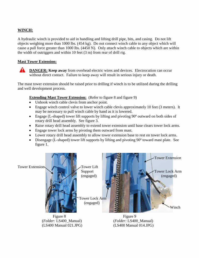
Extending Mast Tower Extension: (Refer to figure 8 and figure 9)
Unhook winch cable clevis from anchor point.
Engage winch control valve to lower winch cable clevis approximately 10 feet (3 meters). It
may be necessary to pull winch cable by hand as it is lowered.
Engage (L-shaped) tower lift supports by lifting and pivoting 90º outward on both sides of
rotary drill head assembly. See figure 3.
Raise rotary drill head assembly to extend tower extension until base clears tower lock arms.
Engage tower lock arms by pivoting them outward from mast.
Lower rotary drill head assembly to allow tower extension base to rest on tower lock arms.
Disengage (L-shaped) tower lift supports by lifting and pivoting 90º toward mast plate. See
figure 1.
Tower Extension
Tower Extension Tower Lift
Support Tower Lock Arm
(engaged) (engaged)
Tower Lock Arm
(engaged)
Winch
Figure 8 Figure 9
(Folder: LS400_Manual) (Folder: LS400_Manual)
(LS400 Manual 021.JPG) (LS400 Manual 014.JPG)

Retracting Mast Tower Extension: (Refer to figure 8 and figure 10)
Engage (L-shaped) tower lift supports by lifting and pivoting 90º outward on both sides of
rotary drill head assembly. See figure 3.
Raise rotary drill head assembly to lift tower extension until base clears tower lock arms.
Pivot tower lock arms 90º away from mast plate. See figure 10.
Lower rotary drill head assembly until mast tower extension is fully retracted.
Disengage (L-shaped) tower lift supports by lifting and pivoting 90º toward mast plate. See
figure 1.
Tower Extension
Tower Lift Support
(engaged)
Tower Lock Arm
(disengaged)
Figure 10
(Folder: LS400_Manual)
(LS400 Manual 024.JPG)
DRILLING PROCEDURE:
WARNING: Use extreme caution when using hydraulic winch. Do not lift objects weighing
more than 1000 lbs. (454 kg). Do not connect winch cable to any object which will cause a pull
force greater than 1000 lbs. (4450 N). Only attach winch cable to objects which are within the
width of outriggers and within 10 feet (3 m) from rear of drill rig.
CAUTION: Keep all safety shields and devices in place.
CAUTION: Make certain everyone is clear before operating.
CAUTION: Read and understand the operator's manual for the mud pump.
Before starting the mud pump, place the 3-way valve in the bypass position. Fill the pits, prime the mud
pump and start the mud pump by following the procedures found in the mud pump operator's manual.
Let it run until good circulation is established.
Raise the rotary drill head to within 12" of the top stops after applying pipe joint compound to swivel
stem threads. Be careful not to jam the shuttle plate into the stops, either top or bottom, as this can cause
undue stress on the draw-works drive components and the mast. If shuttle plate does come into contact
with stops, the chain must be adjusted (refer to Maintenance and Lubrication section for draw-works
chain adjustment).

Apply pipe joint compound to the threads of the swivel stem, the first drill pipe, and the bit. Screw the
drill pipe onto the swivel stem by hand, and then slowly lower the pipe through the slip plate. Screw the
bit onto the end of the pipe by hand. However, for longer, heavier drill pipe, the hydraulic winch may
be used to lift drill pipe into position. Attach the pipe handler to winch cable and drill pipe as shown in
figure 11. After drill pipe is lifted and threaded into position, lower pipe handler down drill pipe so it
may be detached. See figure 12.
Pipe Handler
Figure 11 Figure 12
(Folder: LS_New Rig) (Folder: LS_New Rig)
(LS_New Rig 181.JPG) (LS_New Rig 191.JPG)
After lowering drill pipe through slip plate, loosen slip plate bolts, and place pipe slips around drill pipe.
Ensure drill pipe is running true and level. Tighten slip plate bolts to hold drill pipe in position. See
figure 13.
Slip Plate Bolt Pipe Slips
Slip Plate
Slip Plate Bolt
Figure 13
(Folder: LS400_Manual)
(LS400 Manual 003.JPG)
To start drilling, lower the rotary drive head until the bit just contacts the ground. Place 3-way valve in
the drilling position so that drilling fluid flows out the bit. Move the rotary valve lever to start the bit
rotating in the clockwise direction.

Turn the drill head down pressure valve knob to the fully counterclockwise (open) position. Move the
draw-works valve lever in the lower direction and hold it open. The rotary drill head should not move at
this time. Turn the drill head down pressure valve knob slowly clockwise until the rotary drill head
starts to move downward. Use the drill head down pressure valve to control rate of feed of the drill bit.
Be careful not to move it too fast or bit can become plugged. Monitor cuttings from borehole to make
sure feed rate is correct for type of soil being cut. Harder soils will require more feed force. The system
pressure gauge will give a relative indication of the downward force.
Continue drilling pipe down until the rotary drill head comes to bottom of its travel. The pipe slip jaws
may be closed around the pipe as a guide. (When using 2-3/8” IF pipe, slip jaws cannot be used as a
guide.) Be sure to open the jaws before breakout lugs on the drill pipe come into contact with them. Let
the rotary drive head remain at the bottom for a short time to allow cuttings to clear. Monitor the up-
hole flow to determine when all the cuttings have been removed. Failure to adequately clear cuttings
from borehole may result in bit being trapped as the cuttings fall to the bottom of borehole when fluid
flow is diverted.
Place 3-way valve in bypass position to divert the flow of drilling fluid back to pits. Raise the rotary
drill head far enough to allow slip plate jaws to be closed around the drill pipe. Slowly rotate drill pipe
to position the breakout lugs in line with the opening in the slip, then lower the rotary drill head so that
the bottom of the tool joint is 1 ½" above the slip jaws.
Reverse rotary by lifting valve lever up sharply to the reverse (counterclockwise) direction and holding
it there. The swivel stem will "break out" of the drill pipe and when the pipe is completely unscrewed it
will drop free and fall into slip jaws. Carefully following this procedure will ensure that the threads of
swivel stem and drill pipe remain undamaged.
NOTE: If drill pipe fails to drop free of the swivel stem, then the cuttings were not completely
removed from the borehole.
ADDING PIPE:
- Raise rotary drill head to top of the mast, stopping at least 1" below the top stop.
- Apply pipe joint compound to the threads of swivel stem and drill pipe.
- Screw the new pipe into the box threads of the pipe resting in the slip jaws. Don't completely
tighten. Position the swivel stem threads about 1/2" above the top of the new pipe.
- Open the drill head down pressure valve by turning the knob completely counterclockwise.
- Pull the rotary valve lever partially downward to start the swivel stem turning slowly clockwise.
Pull the draw-works valve lever in the lower position. The rotary drill head should not move at
this time.
- While holding the valve lever open, turn the pressure control knob clockwise until the rotary drill
head starts to move downward slowly. Use the knob and/or the lever to control the rate of
movement as the threads start to engage. It may be necessary to have a helper hold the pipe to
position it in alignment with the swivel stem threads.
- Continue to let rotary drill head move downward as the threads, both top and bottom set, "make
up".
- Just as the threads begin to tighten (both top and bottom sets) return the valve levers to the
neutral positions to stop all movement.
- Push the draw-works valve lever up to raise the rotary drill head and pipe string so that the slip
jaws can be opened.

- Place 3-way valve in the drilling position, wait to make sure circulation is re-established and
fluid comes out the borehole, and continue as above.
COMPLETING THE BOREHOLE:
When the borehole is completed to the required depth, the drill pipe should be removed. Be sure to
allow time for the drilling fluid to circulate and completely clear the borehole of cuttings. Monitor the
outflow to determine when the borehole is clear.
COMING OUT (TRIPPING OUT):
NOTE: Coming out of the borehole should be done quickly to minimize the possibility of
borehole collapsing.
NOTE: This is the time when drill pipe is most likely to be dropped down the borehole. Follow
these steps carefully to prevent this from happening.
- Place 3-way valve in the bypass position. The mud pump is no longer needed and may be shut
off.
- Raise rotary drill head far enough to allow the slip jaws to be closed around the drill pipe closest
to swivel. Rotate drill pipe to position the breakout lugs in line with the openings in the slip,
then lower rotary drill head so that the larger end of the pipe is at least 1" above the slip jaws.
- Reverse rotary by lifting valve lever up sharply to the reverse (counterclockwise) direction but
do not hold it. As soon as the threads start to unscrew return the lever to neutral. Leave no more
than a 1/8" gap between the edges of the tool joints. Move the breakout lever down to engage
breakout to the lock position. It may be necessary to rotate swivel stem slightly to allow
breakout sleeve to engage completely.
- Lift draw-works valve lever to raise the rotary drill head. The slip jaws should remain closed as
the pipe rises. When the next joint appears, quickly open the jaws and then close them after the
joint passes.
NOTE: The preceding instruction does not apply to 2-3/8” IF pipe. The slip jaws cannot be
closed around the body of the pipe. They can only be closed directly below the tool joint.
- Raise rotary drill head far enough to allow the slip plate jaws to be closed around the drill pipe.
Rotate drill pipe to position breakout lugs in line with the openings in the slip, then lower the
rotary drill head so that the bottom of the tool joint is 1 ½" above the slip jaws.
- Reverse the rotary to break out the bottom set of threads, continue reversing until the bottom drill
pipe drops free and the drill string is suspended in the slip jaws.
NOTE: At this point it is very important not to "jam" the drill pipe between the swivel stem and
slip jaws. As the threads are unscrewed, either the rotary drill head must be raised or the drill
pipe must be allowed to drop. It is preferable that the procedure be started with adequate room
below the bottom tool joint so that the drill pipe can drop free.
- Disengage breakout to the unlock position. The drill pipe can now be unscrewed, removed and
placed in the pipe rack. For longer, heavier drill pipe, the hydraulic winch and pipe handler may
be used to assist in removing pipe. See figure 12 and figure 11.

- Lower rotary drill head and engage swivel stem threads into the drill pipe that remains in the slip.
- Do not tighten the threads, but leave a 1/8" gap between the tool joints.
NOTE: Make sure the threads are adequately engaged. Failure to do so can result in the drill
pipe dropping off the swivel stem and being lost down borehole.
- Engage breakout to the lock position.
- Repeat the process until last pipe reaches the surface. If possible, bring the bit up through the
slip plate and then replace pipe slips underneath before unscrewing the last pipe and bit. Place a
cover over the borehole to protect it from falling or dropped objects until casing is ready to be
placed.
TRANSPORTING:
Retract mast tower extension before lowering mast. Also, completely lower rotary drill head assembly
before lowering mast for transport.
IMPORTANT: Always retract draw-works cylinder completely before lowering mast. Towing
drill rig with draw-works cylinder extended will cause cylinder rod to bend and damage cylinder.
Therefore, be sure the rotary drill head assembly is completely lowered before lowering mast for
transport.
Prior to lowering mast, be sure locking wedges are raised using holding pins and roll pins. See figure 5.
Disconnect mud pump and hoses from drill rig. Slowly lower mast to horizontal position while
carefully watching hoses so they do not become snagged or pinched. Make certain outriggers are fully
retracted before transporting. Carefully secure equipment and tools.

SAFETY SIGN LOCATION:
36529
36233
71671
71684
71670 71672
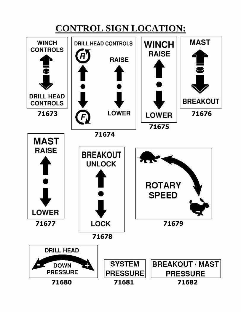
CONTROL SIGN LOCATION:
71673 71676
71675 71674
71677 71679
71678
71680 71681 71682

SAFETY/CONTROL SIGN LIST
PART NUMBERQTYITEM
3623331
7167032
7167313
7167414
7167515
7167616
7167717
7167818
7167919
71680110
71681111
71682112
71671113
71672214
36529315
71684216
1
8
14
15
4
9
12
10
13
11
15
6
3
14
7
5
15
2
2
1
SAFETY/CONTROL SIGN LOCATION:
16
16

1017
IMPORTANT: All nuts, fasteners, and fittings must be kept tightened. Refer to torque chart for proper assembly torque.
HYDRAULIC FITTINGS
SIZE TORQUE SIZE TORQUE
1/4 NPT 25 ft.lb. 7/16-20 SAE O-Ring 12 ft.lb.3/8 NPT 50 ft.lb 9/16-18 SAE O-Ring 20 ft.lb.1/2 NPT 75 ft.lb. 3/4-16 SAE O-Ring 35 ft.lb.3/4 NPT 110 ft.lb. 7/8-14 SAE O-Ring 50 ft.lb.
1-1/16-12 SAE O-Ring 70 ft.lb.
HEX HEADTYPE
S I Z E inch
GRADE 5
GRADE 8
WRENCH SIZE
No. 4 8 in lb 12 in lb 1/4" 12 in lb 3/32"
No. 6 16 in lb 23 in lb 5/16" 21 in lb 7/64"
No. 8 30 in lb 41 in lb 11/32" 42 in lb 9/64"
No.10 43 in lb 60 in lb 3/8" 60 in lb 5/32"
1/4" 8 ft lb 12 ft lb 7/16" 12 ft lb 3/16"
5/16" 17 ft lb 25 ft lb 1/2" 24 ft lb 1/4"
3/8" 30 ft lb 45 ft lb 9/16" 43 ft lb 5/16"
7/16" 50 ft lb 70 ft lb 5/8" 69 ft lb 3/8"
1/2" 75 ft lb 110 ft lb 3/4" 105 ft lb 3/8"
9/16" 110 ft lb 150 ft lb 13/16" 158 ft lb -----
5/8" 150 ft lb 220 ft lb 15/16" 195 ft lb 1/2"
3/4" 260 ft lb 380 ft lb 1-1/8" 353 ft lb 5/8"
WRENCH SIZE

TTTTTHHHHHIIIIINNNNNKKKKKSSSSSAFEAFEAFEAFEAFETTTTTYYYYYFIFIFIFIFIRRRRRSSSSST!T!T!T!T!
P.O. BOX 840 LIVINGSTON, TEXAS 77351PHONE 936/327-3121 FAX 936/327-4025Web: www.littlebeaver.com E-Mail: [email protected]