
LITMANUSRCP2210
194
CP2210 USER MANUAL 020-100410-03
-
Upload
cpatil319311 -
Category
Documents
-
view
68 -
download
2
Transcript of LITMANUSRCP2210

CP2210
U S E R M A N U A L
020-100410-03


CP2210
U S E R M A N U A L
020-100410-03

Table of Contents
CP2210 User Manual i020-100410-03 Rev. 1 (06-2010)
1: Introduction
1.1 Using this Manual........................................................................................................................1-11.2 Typographical Notations .............................................................................................................1-11.3 Safety Warnings and Guidelines .................................................................................................1-2
1.3.1 Labels and Marking .............................................................................................................1-21.3.2 General Precautions .............................................................................................................1-21.3.3 AC/Power Precautions.........................................................................................................1-3
Power Cords and Attachments .............................................................................................1-31.3.4 Lamp Precautions ................................................................................................................1-3
Wear Protective Clothing .....................................................................................................1-3Cool the Lamp Completely ...................................................................................................1-4
1.4 Purchase Record and Service Contacts .......................................................................................1-41.5 Projector Overview......................................................................................................................1-5
1.5.1 Key Features ........................................................................................................................1-51.5.2 How the Projector Works ....................................................................................................1-61.5.3 Air Filter Cover and Air Filter.............................................................................................1-61.5.4 Douser..................................................................................................................................1-61.5.5 Adjustable Feet ....................................................................................................................1-71.5.6 Lamp Door and Lamps ........................................................................................................1-71.5.7 LED Status Indicators..........................................................................................................1-71.5.8 Optional - Motorized Auxiliary Lens Mount (MALM).......................................................1-71.5.9 Projection Lens ....................................................................................................................1-71.5.10 Security Locks ..................................................................................................................1-71.5.11 Source and Communication Panel ....................................................................................1-8
PIB Faceplate Connections ...................................................................................................1-8PIB Faceplate Status Indicators ............................................................................................1-8ICP Faceplate Connections ...................................................................................................1-9
1.5.12 Touch Panel Controller (TPC)..........................................................................................1-101.5.13 List of Components...........................................................................................................1-10
2: Installation and Setup
2.1 Tools Required for Installation....................................................................................................2-12.2 Installation Instructions ...............................................................................................................2-2
2.2.1 Step 1: Position the Projector...............................................................................................2-22.2.2 Step 2: Adjust Tilt/Leveling ................................................................................................2-32.2.3 Step 3: Mount Touch Panel Controller (TPC) .....................................................................2-32.2.4 Step 4: Connect Exhaust Ducting (Optional) ......................................................................2-42.2.5 Step 6: Install Lens ..............................................................................................................2-5
Primary Zoom Lens Installation ...........................................................................................2-5Anamorphic Lens Installation ..............................................................................................2-6Wide Converter Lens (WCL) Installation ............................................................................2-6Motorized Auxiliary Lens Mount (MALM) Installation (Optional) ....................................2-6
2.2.6 Step 7: Install First Lamp.....................................................................................................2-72.2.7 Step 8: Connect to Power.....................................................................................................2-82.2.8 Step 9: Connect Sources ......................................................................................................2-9

ii CP2210 User Manual020-100410-03 Rev. 1 (06-2010)
Table of Contents
2.3 Connecting Sources .....................................................................................................................2-102.3.1 Cinema Servers ....................................................................................................................2-102.3.2 Connecting for Communications .........................................................................................2-11
PC/Laptop, Server or Network .............................................................................................2-112.4 Maximizing Light Output ............................................................................................................2-122.5 Calibrating Screen Brightness (fL) ..............................................................................................2-122.6 Basic Image Alignment ...............................................................................................................2-13
2.6.1 Basic Optical Alignment Procedure.....................................................................................2-132.7 Offset and Boresight Alignment...........................................................................................................2-13
2.7.1 Adjust Offset ........................................................................................................................2-132.7.2 Adjusting Left/Right Boresight............................................................................................2-14
Lens Mount Vertical Boresight .............................................................................................2-14Lens Mount Horizontal Boresight ........................................................................................2-15
2.7.3 Add Anamorphic Lens .........................................................................................................2-162.7.4 Wide Converter Lens ...........................................................................................................2-16
2.8 Fold Mirror and Convergence Adjustments ................................................................................2-172.8.1 DMD Convergence ..............................................................................................................2-172.8.2 Fold Mirror Adjustment .......................................................................................................2-17
2.9 Calibrating the System.................................................................................................................2-182.9.1 Color Calibration..................................................................................................................2-182.9.2 Electronic Screen Masking ..................................................................................................2-18
3: Operation
3.1 Powering Up/Powering Down the Projector................................................................................3-13.1.1 Powering Up the Projector ...................................................................................................3-13.1.2 Powering Down the Projector ..............................................................................................3-23.1.3 Projector Power States .........................................................................................................3-2
3.2 Using the Touch Panel Controller (TPC) ....................................................................................3-23.3 Main Panel ...................................................................................................................................3-3
Aux Lens ...............................................................................................................................3-5Lens Adjust ...........................................................................................................................3-5Test Patterns ..........................................................................................................................3-6
3.3.1 Navigating the User Interface ..............................................................................................3-7Title Bar ................................................................................................................................3-7Menu Button .........................................................................................................................3-7On Screen Keyboard .............................................................................................................3-7
3.4 User Access and Rights ...............................................................................................................3-83.5 TPC Windows..............................................................................................................................3-10
3.5.1 Status Window .....................................................................................................................3-103.5.2 Alarm Window.....................................................................................................................3-143.5.3 Projector LED Status Indicators ..........................................................................................3-143.5.4 Diagnostics Window............................................................................................................3-15
Diagnostics: Interrogator Window ........................................................................................3-15Diagnostics: SMPTE Errors Window ...................................................................................3-16Diagnostics: System Logs Window ......................................................................................3-17Diagnostics: DLP Management Window .............................................................................3-18

Table of Contents
CP2210 User Manual iii020-100410-03 Rev. 1 (06-2010)
3.5.5 Network Devices..................................................................................................................3-193.5.6 Channel Setup Windows......................................................................................................3-21
Channel Setup: Config 1 Window ........................................................................................3-22Channel Setup: Config 2 Window ........................................................................................3-25Channel Setup: 3D Control Window ....................................................................................3-26
3.5.7 Advanced Setup Window ....................................................................................................3-29Advanced Setup: Lamp Power / LiteLOC™ Setup Window ...............................................3-30Advanced Setup: Lamp History Window .............................................................................3-32Add Lamp Window ..............................................................................................................3-33Advanced Setup: LampLOC™ Setup Window ....................................................................3-34Advanced Setup: ILS File Setup Window ............................................................................3-35Advanced Setup: Lens Setup Window .................................................................................3-37Advanced Setup: Source File Setup Window .......................................................................3-39Advanced Setup: Screen File Setup Window .......................................................................3-41Advanced Setup: MCGD File Setup Window ......................................................................3-44Advanced Setup: TCGD File Setup Window .......................................................................3-45
3.5.8 Administrator Setup Window ..............................................................................................3-47Administrator Setup: Preferred Channel Setup Window .....................................................3-47Administrator Setup: Preferred Test Pattern Setup Window ................................................3-48Administrator Setup: Preferences Window ..........................................................................3-50Administrator Setup: Time Setup Window ..........................................................................3-52Administrator Setup: Communications Configuration Window ..........................................3-53Administrator Setup: Network Devices Window .................................................................3-55Administrator Setup: GPIO Setup Window .........................................................................3-56Administrator Setup: Foot Lamberts Calibration Window ..................................................3-57Administrator Setup: User Accounts Window .....................................................................3-60To Add a New User ..............................................................................................................3-61Administrator Setup: Upgrade Window ...............................................................................3-62Steps to Install an Upgrade Package .....................................................................................3-62
3.5.9 Service Setup .......................................................................................................................3-66Service Setup: File Management Window ...........................................................................3-66To Restore Backup Files .......................................................................................................3-67Service Setup: Marriage Window .........................................................................................3-67Service Setup: System Access Window ...............................................................................3-71
3.5.10 About Window..................................................................................................................3-723.5.11 Help Window....................................................................................................................3-73
3.6 Working with the Lamp...............................................................................................................3-743.6.1 Turning the Lamp ON..........................................................................................................3-74
If the Lamp Fails to Ignite ....................................................................................................3-753.6.2 Turning the Lamp OFF........................................................................................................3-753.6.3 Adjusting Lamp Power ........................................................................................................3-753.6.4 Adjusting Lamp Position (LampLOC™) ............................................................................3-773.6.5 Calibrating Screen Brightness (fL) ......................................................................................3-793.6.6 Age of a Lamp .....................................................................................................................3-79
3.7 Working with the Lenses.............................................................................................................3-803.7.1 Lens Mount Functions .........................................................................................................3-81

iv CP2210 User Manual020-100410-03 Rev. 1 (06-2010)
Table of Contents
3.7.2 Reset the ILS........................................................................................................................3-823.7.3 Calibrate the ILS ..................................................................................................................3-82
3.8 Working with 3D .........................................................................................................................3-823.8.1 Hardware Requirements for 3D Cinema Setups ..................................................................3-833.8.2 Hardware Setup....................................................................................................................3-833.8.3 Installation for 3D Servers with YCxCz Interface...............................................................3-84
Procedure Overview .............................................................................................................3-84Lamp Instructions .................................................................................................................3-84Measured Color Gamut Data (MCGD) Instructions .............................................................3-84Channel Setup Instructions ...................................................................................................3-85
3.8.4 System Test Pattern..............................................................................................................3-883.8.5 Verify 3D Cinema Content ..................................................................................................3-913.8.6 3D Troubleshooting .............................................................................................................3-91
3.9 Cinema Operation ........................................................................................................................3-923.9.1 Compatible Cinema Sources................................................................................................3-923.9.2 Image Formats......................................................................................................................3-92
Projector Variables: Using an Anamorphic Lens .................................................................3-92Projector Variables: Using a Wide Converter Lens ..............................................................3-93Theatre Variables: Masking ..................................................................................................3-93
3.10 Non-Cinema Operation..............................................................................................................3-943.10.1 Selecting a Source.............................................................................................................3-94
4: Maintenance
4.1 AC/Power Precautions.................................................................................................................4-14.2 Lamp Precautions ........................................................................................................................4-2
4.2.1 Wear Protective Clothing.....................................................................................................4-24.2.2 Cool the Lamp Completely ..................................................................................................4-2
4.3 Maintaining Proper Cooling ........................................................................................................4-34.3.1 Ventilation............................................................................................................................4-3
4.4 Preventative Maintenance............................................................................................................4-34.4.1 Light Engine Air Filter (P/N: 003-101463-xx) ....................................................................4-34.4.2 Radiator Filter ......................................................................................................................4-34.4.3 Liquid Cooler .......................................................................................................................4-4
Filling the Coolant Reservoir ................................................................................................4-44.4.4 Optional: Exhaust Duct (P/N: 119-103105-xx) ...................................................................4-4
4.5 Maintenance and Cleaning...........................................................................................................4-54.5.1 Lamp ....................................................................................................................................4-54.5.2 Optical ..................................................................................................................................4-5
Optical Component Cleaning Supplies .................................................................................4-54.5.3 Cleaning the Lens.................................................................................................................4-64.5.4 Cleaning the Lamp Reflector ...............................................................................................4-64.5.5 Other Components ...............................................................................................................4-7
Lamp Blower ........................................................................................................................4-74.5.6 Lamp Replacement ..............................................................................................................4-74.5.7 Rotating the Lamp................................................................................................................4-94.5.8 Air Filter Replacement.........................................................................................................4-10

Table of Contents
CP2210 User Manual v020-100410-03 Rev. 1 (06-2010)
Light Engine Air Filter .........................................................................................................4-10Radiator Filter Replacement .................................................................................................4-10
4.6 Lens Replacement........................................................................................................................4-114.6.1 Remove Lens .......................................................................................................................4-114.6.2 Install New Lens ..................................................................................................................4-12
5: Troubleshooting
5.1 Power ...........................................................................................................................................5-15.1.1 Projector Does Not Power ON.............................................................................................5-1
5.2 Lamp............................................................................................................................................5-25.2.1 Lamp Does Not Ignite..........................................................................................................5-25.2.2 Lamp Suddenly Goes OFF ..................................................................................................5-25.2.3 Flicker, Shadows Or Dimness .............................................................................................5-35.2.4 LampLOC™ Does Not Seem to Work................................................................................5-35.2.5 LiteLOC™ Does Not Seem to Work...................................................................................5-3
5.3 ILS ...............................................................................................................................................5-35.3.1 Reset the ILS........................................................................................................................5-35.3.2 Calibrate the ILS..................................................................................................................5-4
5.4 TPC..............................................................................................................................................5-45.5 Ethernet........................................................................................................................................5-4
5.5.1 Trouble Establishing Communication with Projector .........................................................5-45.6 Displays .......................................................................................................................................5-4
5.6.1 Blank Screen, No Display of Cinema Image.......................................................................5-45.6.2 Severe Motion Artifacts.......................................................................................................5-55.6.3 Image Appears Vertically Stretched or ‘Squeezed’ into Center of Screen..........................5-55.6.4 No Image, Just Pink Snow...................................................................................................5-55.6.5 Colors in the Display are Inaccurate...................................................................................5-55.6.6 Display is Not Rectangular .................................................................................................5-55.6.7 Display is “Noisy” ..............................................................................................................5-65.6.8 Display has Suddenly Frozen .............................................................................................5-65.6.9 Data is Cropped from Edges...............................................................................................5-65.6.10 The Projector is ON, but There is No Display..................................................................5-65.6.11 The Display is Jittery or Unstable.....................................................................................5-65.6.12 The Display is Faint..........................................................................................................5-75.6.13 The Upper Portion of the Display is Waving, Tearing or Jittering...................................5-75.6.14 Portions of the Display are Cut OFF or Warped to the Opposite Edge............................5-75.6.15 Display Appears Compressed (Vertically Stretched) .......................................................5-75.6.16 Display Quality Appears to Drift from Good to Bad, Bad to Good .................................5-7
6: Specifications
6.1 Display.........................................................................................................................................6-16.1.1 Panel Resolution and Refresh Rate......................................................................................6-16.1.2 Achievable Brightness (Measured at Screen Center) ..........................................................6-16.1.3 Achievable Contrast Ratio ...................................................................................................6-16.1.4 Color and Gray Scale...........................................................................................................6-1

vi CP2210 User Manual020-100410-03 Rev. 1 (06-2010)
Table of Contents
6.1.5 White Point ..........................................................................................................................6-16.1.6 Gamma.................................................................................................................................6-2
6.2 Source Signal Compatibility ........................................................................................................6-26.2.1 Cinema Inputs ......................................................................................................................6-26.2.2 Non-Cinema DVI Inputs (for Alternate Content)................................................................6-4
6.3 Control Signal Compatibility.......................................................................................................6-56.3.1 Ethernet Port ........................................................................................................................6-56.3.2 RS232-PIB ...........................................................................................................................6-56.3.3 RS232-ICP ...........................................................................................................................6-56.3.4 GPIO Port.............................................................................................................................6-56.3.5 Simple Contact Closure Interface (SCCI) Port ....................................................................6-66.3.6 3D Port .................................................................................................................................6-66.3.7 MALM (located on Auxiliary Input Panel) .........................................................................6-6
6.4 Touch Panel Controller ................................................................................................................6-66.5 Power Requirements ....................................................................................................................6-7
6.5.1 AC Input...............................................................................................................................6-76.5.2 UPS AC Input ......................................................................................................................6-7
6.6 Lamp ............................................................................................................................................6-76.7 Physical Specifications ................................................................................................................6-86.8 Regulatory....................................................................................................................................6-8
6.8.1 Safety ...................................................................................................................................6-86.8.2 Electro-Magnetic Compatibility ..........................................................................................6-8
Emissions ..............................................................................................................................6-8Immunity ...............................................................................................................................6-8Environmental .......................................................................................................................6-8
6.9 Environment.................................................................................................................................6-96.9.1 Operating Environment.......................................................................................................6-96.9.2 Non-Operating Environment...............................................................................................6-9
6.10 Accessories ................................................................................................................................6-96.10.1 Standard (sold with product).............................................................................................6-96.10.2 Accessories (sold separately) ............................................................................................6-9
A: Serial API
B: SCCI Port
C: GPIO Port

NOTICES
COPYRIGHT AND TRADEMARKS
© 2010 Christie Digital Systems USA, Inc. All rights reserved.
All brand names and product names are trademarks, registered trademarks or trade names of their respective holders.
REGULATORY
The product has been tested and found to comply with the limits for a Class A digital device, pursuant to Part 15 of the FCC Rules. These limits are designed to provide reasonable protection against harmful interference when the product is operated in a commercial environment. The product generates, uses, and can radiate radio frequency energy and, if not installed and used in accordance with the instruction manual, may cause harmful interference to radio communications. Operation of the product in a residential area is likely to cause harmful interference in which case the user will be required to correct the interference at the user’s own expense.
This Class A digital apparatus complies with Canadian ICES-003.Cet appareil numérique de la classe A est conforme à la norme NMB-003 du Canada.
이이이이 기기는기기는기기는기기는 업무용업무용업무용업무용 (A급급급급 )으로으로으로으로 전자파적합등록을전자파적합등록을전자파적합등록을전자파적합등록을 한한한한 기기이오니기기이오니기기이오니기기이오니 판매자판매자판매자판매자 또는또는또는또는 사용자는사용자는사용자는사용자는 이점을이점을이점을이점을 주의하시기주의하시기주의하시기주의하시기 바라며바라며바라며바라며 , 가정가정가정가정 외의외의외의외의 지역에서지역에서지역에서지역에서 사용하는사용하는사용하는사용하는 것을것을것을것을
목적으로목적으로목적으로목적으로 합니다합니다합니다합니다 .
GENERAL
Every effort has been made to ensure accuracy, however in some cases changes in the products or availability could occur which may not be reflected in this document. Christie reserves the right to make changes to specifications at any time without notice. Performance specifications are typical, but may vary depending on conditions beyond Christie's control such as maintenance of the product in proper working conditions. Performance specifications are based on information available at the time of printing. Christie makes no warranty of any kind with regard to this material, including, but not limited to, implied warranties of fitness for a particular purpose. Christie will not be liable for errors contained herein or for incidental or consequential damages in connection with the performance or use of this material.
The product is designed and manufactured with high-quality materials and components that can be recycled and reused. This symbol
means that electrical and electronic equipment, at their end-of-life, should be disposed of separately from regular waste. Please dispose of the product appropriately and according to local regulations. In the European Union, there are separate collection systems for used electrical and electronic products. Please help us to conserve the environment we live in!
Canadian manufacturing facility is ISO 9001 and 14001 certified.
WARRANTY
For complete information about Christie’s limited warranty, please contact your Christie dealer. In addition to the other limitations that may be specified in Christie’s limited warranty, the warranty does not cover:
a. Damage occurring during shipment, in either direction.b. Projector lamps (See Christie’s separate lamp program policy).c. Damage caused by use of a projector lamp beyond the recommended lamp life, or use of a lamp supplied by a supplier other than Christie.d. Problems caused by combination of the product with non-Christie equipment, such as distribution systems, cameras, video tape recorders, etc., or use of the product with any non-Christie interface device.
e. Damage caused by misuse, improper power source, accident, fire, flood, lightening, earthquake or other natural disaster.f. Damage caused by improper installation/alignment, or by product modification, if by other than a Christie authorized repair service provider.
g. For LCD projectors, the warranty period specified applies only where the LCD projector is in “normal use.” “Normal use” means the LCD projector is not used more than 8 hours a day, 5 days a week. For any LCD projector where “normal use” is exceeded, warranty coverage under this warranty terminates after 6000 hours of operation.
h. Failure due to normal wear and tear.
PREVENTATIVE MAINTENANCE
Preventative maintenance is an important part of the continued and proper operation of your product. Please see the Maintenance section for specific maintenance items as they relate to your product. Failure to perform maintenance as required, and in accordance with the maintenance schedule specified by Christie, will void the warranty.

CP2210 User Manual 1-1020-100410-03 Rev. 1 (06-2010)
1 Introduction
1.1 Using this Manual
USERS/OPERATORS: This manual is intended for trained users authorized to operate professional high-brightness projection systems, located in restricted areas, such as projection rooms in theatres. Such users may also be trained to replace the lamp and air filter, but cannot install the projector or perform any other functions inside the projector. NOTE: Only personnel trained specifically by Christie on lamp replacement and lamp safety may handle the lamp.
SERVICE: Only qualified Christie trained service technicians knowledgeable about all potential hazards associated with high voltage, ultraviolet exposure and high temperatures generated by the lamp and associated circuits are authorized to 1) assemble/install the projector and 2) perform service functions inside the projector.
This manual contains the following sections:
• Section 1 Introduction• Section 2 Installation and Setup• Section 3 Operation• Section 4 Maintenance• Section 5 Troubleshooting• Section 6 Specifications• Appendix A: Serial API• Appendix B: SCCI Port• Appendix C: GPIO Port
Disclaimer: Every effort has been made to ensure the information in this document is accurate and reliable. However, due to constant research, the information in this document is subject to change without notice. Christie Digital Systems assumes no responsibility for omissions or inaccuracies. Updates to this document are published regularly, as required. Please contact Christie Digital Systems for availability.
1.2 Typographical Notations
The following notations are used throughout this manual:
• References to specific areas of the document appear italicized and underlined. When viewed online the text appears in blue indicating a direct link to that section. For example, Section 2 Installation and Setup.
• References to other documents appear italicized and bold, such as Service Manual. • References to software menus and available options appear bold, such as Main panel, Preferences.• User input or messages that appear on screen, in status display units or other control modules appear in
Courier font. For example. “No Signal Present”, Login: christiedigital.
• Error codes, LED status appear in bold, e.g. LP, A1 etc.• Operational states of modules appear capitalized, such as power ON/OFF.

1-2 CP2210 User Manual020-100410-03 Rev. 1 (06-2010)
Section 1: Introduction
1.3 Safety Warnings and Guidelines
1.3.1 Labels and Marking
Observe and follow any warnings and instructions marked on the projector.
Danger symbols indicate a hazardous situation which, if not avoided, will resultin death or serious injury. This signal word is to be limited to the most extreme situations.
Warning symbols indicate a hazardous situation which, if not avoided, couldresult in death or serious injury.
Caution symbols indicate a hazardous situation which, if not avoided, couldresult in minor or moderate injury.
NOTICE! Addresses practices not related to personal injury.
The exclamation point within the equilateral triangle indicates related operating/maintenance instructions in the documentation accompanying the projector.
The lightning flash and arrowhead symbol within the equilateral triangle indicates non-insulated “dangerous voltage” within the projector's enclosure that may be of sufficient magnitude to constitute a risk of electric shock.
1.3.2 General Precautions
Never look directly into the projector lens or at the lamp. The extremely highbrightness can cause permanent eye damage. For protection from ultraviolet radiation, keepall projector housings intact during operation. Protective safety gear and safety goggles arerecommended when servicing.
FIRE HAZARD! Keep hands, clothes, and all combustible material away fromthe concentrated light beam of the lamp.
Position all cables where they cannot contact hot surfaces or bepulled or tripped over.
1) The American Conference of Governmental Industrial Hygienists(ACGIH) recommends occupational UV exposure for an 8-hour day to be less than0.1 microwatts per square centimeters of effective UV radiation. An evaluation ofyour workplace is advised to assure employees are not exposed to cumulativeradiation levels exceeding the government guidelines for your area. 2) Be awarethat some medications are known to increase sensitivity to UV radiation.
This projector must be operated in an environment that meets the operating range specification, as listed in Section 6 Specifications.
DANGER
WARNING
WARNING
WARNING

Section 1: Introduction
CP2210 User Manual 1-3020-100410-03 Rev. 1 (06-2010)
1.3.3 AC/Power Precautions
1) Use only the AC power cord supplied. DO NOT attempt operation if the AC supply is not within the specified voltage and power range. For details, refer to Section 6 Specifications.
2) As a safety feature the projector is equipped with a three-wire plug with a third (grounding) pin. If you are unable to insert the plug into the outlet, contact an electrician to have the outlet replaced. DO NOT defeat the safety purpose of the grounding-type plug.
3) DO NOT attempt operation if the AC supply is not within the rated voltage range, as specified on the licence label.
4) Disconnect projector from AC before opening any enclosure.
1) DO NOT allow anything to rest on the power cord. Locate the projector where the cordcannot be abused by persons walking on it or objects rolling over it. Never operate theprojector if the power cable appears damaged in any way.
2) DO NOT overload power outlets and extension cords as this can result in fire or shockhazards.
3) Note that only qualified service technicians are permitted to open any enclosure on theproduct and only if the AC has been fully disconnected from the product.
Power Cords and Attachments
The North American rated line cord is provided with each projetor. Ensure that you are using a line cord, socket and power plug that meets the appropriate local rating standards. Use only an AC power cord recommended by Christie. DO NOT attempt operation if the AC supply and cord are not within the specified voltage and power range.
NOTICE! Use only the attachements and/or accessories recommended by Christie. Use of others may result in the risk of fire, shock and personal injury.
1.3.4 Lamp Precautions
EXPLOSION HAZARD! Wear authorized protective safety gear whenever the lamp door is open! Never attempt to remove the lamp directly after use. The lamp is under significant pressure when hot and cold, and may explode, causing personal injury and/or property damage.
Any lamp used in the CP2210 is under high pressure and must be handled with great care at all times. Lamps may explode if dropped or mishandled.
Wear Protective Clothing
Never open the lamp door unless you are wearing authorized protective clothing such as that included in a Christie Protective Clothing Safety Kit (P/N: 598900-095). Recommended protective clothing includes, but may not be limited to a polycarbonate face shield, protective gloves, and a quilted ballistic nylon jacket or a welder’s jacket. NOTE: Christie’s protective clothing recommendations are subject to change. Any local or federal specifications take precedence over Christie recommendations.
WARNING
WARNING
DANGER

1-4 CP2210 User Manual020-100410-03 Rev. 1 (06-2010)
Section 1: Introduction
Cool the Lamp Completely
Lamp may explode causing bodily harm or death. Always wear protective clothing whenever lamp door is open or while handling lamp. Ensure those within the vicinity of the projector are also suited with protective clothing. Never attempt to access the lamp while the lamp is ON. Wait at least 10 minutes after the lamp turns OFF before powering down, disconnecting from AC and opening the lamp door.
1.4 Purchase Record and Service Contacts
Whether the projector is under warranty or the warranty has expired, Christie’s highly trained and extensive factory and dealer service network is always available to quickly diagnose and correct projector malfunctions. Complete service manuals and updates are available for all projectors. Should a problem be encountered with any part of the projector, contact your dealer. In most cases, servicing is performed on site. If you have purchased the projector, fill out the information below and keep with your records.
* The serial number can be found on the license label located on the front panel.
Table 1.1 Purchase Record
Dealer:
Dealer or Christie Sales/Service Contact Phone Number:
Projector Serial Number*:
Purchase Date:
Installation Date:
Table 1.2 Ethernet Settings
Default Gateway
Projector IP Address
Subnet Mask
DANGER

Section 1: Introduction
CP2210 User Manual 1-5020-100410-03 Rev. 1 (06-2010)
1.5 Projector Overview
The CP2210 is a professional quality, easy-to-use DMD™ projector utilizing Digital Light Processing (DLP™) Cinema technology from Texas Instruments. It’s all-in-one design integrates all components in a sleek projection head that can be table-top mounted or used with the optional rack stand. Integrating smoothly into traditional projection environments such as theatres and other wide screen exhibitor venues, the CP2210 offers stunning wide screen, high-resolution cinema images that remain flawless from first release to final show. The CP2210 interfaces with local networks typical in theatres throughout the world, and can be expanded even further by connecting non-cinema DVI source material for multimedia presentations from a variety of formats.
1.5.1 Key Features
• Three-chip mDC2K DLP Cinema® light engine.• .98” “mDC2K” panel format: 2,048(H) x 1,080 (V).• Maximum light output of 12,500 centre lumens, depending on lamp used.• Available for use with 2.0kW, 1.8kW and 1.4kW Xenon lamps supporting theatre screens up to 30 feet in
width.• All-in-one design (including ballast).• CineBlack™ contrast management for contrast ratios of 450:1 ANSI and 2100:1 full field.• CinePalette™ color management for film-like colorimetry.• Easily accessible Input/Output panel located on the operator side of the projector with access to:
• Two SMPTE 292M inputs, intended for cinema content – operable as two independently selectable inputs or as a single dual-link input (both inputs used simultaneously for one source).
• Two DVI-D inputs, intended for alternative content – operable as two independently selectable inputs or as a single twin- or dual-link input (dual-link requires optional adapter).
• RS232 Connections – one for Projector Intelligence Board (PIB) and one for TI electronics (ICP).• Single projector Ethernet network connection.• Dedicated 3D connection plug for interfacing with third party 3D systems.
• Easy-to-read three coloured LED indicators on the rear corners of the projector for status indication.• Supports CineLink® II link encryption on SMPTE 292M inputs.• LiteLOC™ feature for constant image brightness.• LampLOC™ feature for motorized three-axis lamp alignment (automatic or individually adjusted).• Available suite of field-interchangeable “prime” zoom lenses supporting 1.85:1 and 2.39:1 image formats.• Prime lens provides electronic adjustment of focus (stepper motor). *Manual adjustment is available in case of motor failure.
• Prime lens provides electronic adjustment of zoom (stepper motor).• Lens mount provides electronic adjustment of horizontal and vertical offset (stepper motors).• Optional Motorized Auxiliary Lens Mount for flat to scope format conversion (for optional 1.25x anamor-
phic or 1.26x converter lens).
Figure 1-1 CP2210 Projector

1-6 CP2210 User Manual020-100410-03 Rev. 1 (06-2010)
Section 1: Introduction
• Lamp easily replaceable via locked door on rear of projector.• Electronically operated “quick” douser.• Field adjustable RGB Convergence.• Easy-to-remove Light Engine including a permanently mounted handle and quick disconnects for cooling
and electrical connections.• Secure, encrypted communication protocol, with multi-level password access.• Content protected by a high-security Medeco® lock on front electronics compartment and SPB2 boundary
per DCI Digital Cinema System Specification v1.2.• Complies with DCI Digital Cinema System specification v1.2 mandated security requirements.• Air filter for projection compartment that is easily replaceable with common tools.• Optional Rack Mount Stand that supports the product for projection out standard theatre port windows and
provides for rack mounting of hardware.• Capability to split power supply to allow use of UPS (Uninterruptable Power Supply) to power head
electronics.• Touch Panel Controller (TPC) running Windows XPe for main projector interface. TPC can be removed
from the projector for ease of use or alternate mounting with optional extension cable. Ensure you have the latest software by visiting www.christiedigital.com.
• Seamless switching between 292 and DVI inputs.• Capable of supporting an internal image media block.• Easily serviceable LVPS with quick disconnects.• Separate and easily serviceable standby LVPS with quick disconnects.• Easy access for lamp power supply (LPS) removal.• Projector can be self-cooling or utilize external air extraction, depending on theatre configuration.
1.5.2 How the Projector Works
The CP2210 accepts a variety of cinema or DVI-compatible “non-cinema” signals for projection on screens typical in commercial theatre or other large screen applications. High-brightness light is generated by ashort arc Xenon lamp, then modulated by three Digital Micromirror Device (DMD) panels responding toincoming data streams of digitized red, green and blue color information. As these digital streams flow fromthe source, light from the responding “on” pixels of each panel is reflected, converged and then projected to thescreen through one or more front lenses, where all pixel reflections are superimposed in sharp full-colorimages.
1.5.3 Air Filter Cover and Air Filter
Located directly behind the air filter cover is a field replaceable air filter. The air filter is responsible for filtering the intake air before it begins circulating in the front compartment to cool the main electronics. Replace the air filter whenever the lamp is replaced or sooner in dusty/dirty environments. Check the condition monthly. Refer to 4.5.8 Air Filter Replacement, on page 4-10 for complete instructions.
1.5.4 Douser
For most instances, use the douser control buttons on the TPC to blank the display for instant picture muting. Closing the douser rotates a shutter blade in front of the illumination system and reduces lamp power to conserve lamp life.

Section 1: Introduction
CP2210 User Manual 1-7020-100410-03 Rev. 1 (06-2010)
1.5.5 Adjustable Feet
For many cinema installations, the projector is inclined slightly forward to match screen tilt and to minimize the amount of vertical offset required. Turn the adjustable feet to increase or decrease the projector height as needed for proper leveling and/or slight tilt. Refer to 2.2.2 Step 2: Adjust Tilt/Leveling, on page 2-3 for details on how to adjust the feet and how to properly secure the projector.
1.5.6 Lamp Door and Lamps
Located on the back of the projector is the lamp access door designed with a mid-security lock. The lamp door must remain closed and locked for all normal operation. Lamp replacement should only be performed by qualified technicians.
The projector is designed to operate with 2.0kW, 1.8kW and 1.4kW lamps. For a complete list of available lamp types refer to Section 6 Specifications.
1.5.7 LED Status Indicators
Located in the rear corners of the projector are two sets of LEDs, which illuminate to provide continuous feedback of the projector’s status. Refer to Section 3 Operation for details on the various LED states.
1.5.8 Optional - Motorized Auxiliary Lens Mount (MALM)
The MALM assembly is an optional hardware component, which when needed can be used to switch from flat to “scope” formats. This assembly can be secured to the projector base and supports either a 1.25x anamorphic lens or a 1.26x wide converter lens (WCL). The drive and control electronics package for this motorized accessory lens mount communicates with and is controlled by the projector over a 9-pin subminiature D cable that connects to the Auxiliary Input Panel.
1.5.9 Projection Lens
A variety of lenses can be used with the CP2210. Refer to the Section 6 Specifications for a list of available lenses.
1.5.10 Security Locks
Critical internal components and/or connections are protected by various security locks on projector covers/access panels. This safeguard enables only authorized personnel to access certain restricted areas of the projector. The projector’s panels cannot be removed with standard tools unless the key locks are open.
• Panels with high-security lock: Light Engine and Cardcage• Panels with low-security lock: Rear Access Door• No locks: Air Filter Access Panel

1-8 CP2210 User Manual020-100410-03 Rev. 1 (06-2010)
Section 1: Introduction
1.5.11 Source and Communication Panel
PIB Faceplate Connections
Located on the operator’s side of the projector (left side) is a communication panel that provides connection of external devices such as servers and a controller.
• Ethernet: Use the 10Base-T/100Base-TX Ethernet port for network connection to the projector.• GPIO: Connect external I/O devices, such as the Christie ACT, for remote control of a limited number of
projector functions. Refer to Appendix C: GPIO Port for GPIO pinouts.• SCCI: A Simple Contact Closure Interface (SCCI) port that provides the following functions upon a simple
dry contact closure: Lamp ON/OFF and Douser Open/Closed. Refer to Appendix B: SCCI Port for SCCI pinouts.
• RS232 ICP: Connect a PC or laptop for direct DLP communication. Trained users required.• RS232 PIB: Utilizes Christie-proprietary protocol and is intended for Christie accessories or third-party
automation equipment. • 3D: Connect a variety of 3D products to this connector, such as MasterImage or Real D for polarizing and
de-ghosting 3D content during projection.• Marriage: Marriage must be established to allow the projector to play encrypted content. This means the
security boundaries SPB1 and SPB2 are physically and electrically connected and that marriage is monitored 24/7. Marriage is initiated from a Wizard application on the TPC. A user with the appropriate credentials is prompted to press the Marriage button to establish marriage. If the button is pressed any other time it is ignored. Marriage cannot be established remotely.
• Emergency Start: This button is recessed into the faceplate to prevent accidental activation. It should only be used when the TPC has failed or is disconnected. When pressed, the projector is powered on, the lamp is powered up and the douser is opened. When you press and hold this button, the douser is closed and the lamp is powered OFF, but power is still ON.
• Reset: This button is slightly recessed into the faceplate to prevent accidental activation. It’s main purpose is to reset the electronics of the projector. After re-booting, the projector will return to its previous power mode (STANDBY or FULL power), however the lamp will not strike automatically and requires manual striking.
• DVI-A / DVI-B: Connect a variety of non-cinema video and graphics sources to either of these identical single-link DVI ports. These are single-link ports for single-link cables/connectors only. The connectors can be used together as a twin-link DVI port.
• HD-SDI A/HD-SDI-B: Connect a variety of high-definition cinema sources to these SMPTE 292M bit-serial standard interface BNCs. The connectors can be used together to deliver Dual Link HD-SDI following the SMPTE 372M standard.
PIB Faceplate Status Indicators
• STBY: Standby power (Single Color Green) indicates the presence of +24V from the standby power supply.• OFF: Indicates no standby power (breaker OFF or Standby power failure).• Green: Indicates standby power.
• PWR: Main power (Single Color Green) indicates the presence of +24V from the Low Voltage Power Supply (LVPS).
• OFF: No LVPS power (STANDBY mode or breaker OFF).• Green: Indicates full power.
• RUN: Blinking heartbeat (bi-color green/yellow).• OFF or Solid Green: Indicates projector not functioning properly.

Section 1: Introduction
CP2210 User Manual 1-9020-100410-03 Rev. 1 (06-2010)
• Blinking Green: OK (software/communication/OS/ICP/Enigma/IMB if present are operating normally).
• Solid Yellow: Communication error. NiOS functioning OK, but can no longer communicate with TPC.• PIB: Projector Intelligence Board Status (Bi-color Red/Green)
• OFF: Not detected.• Red: Detected communication problems etc.• Blinking Red: PIB card seating error.• Green: Detected and working properly.
• ICP: Integrated Cinema Processor Status (Bi-color Red/Green)• OFF: Not detected.• Red: Detected communication problems etc.• Green: Detected and working properly.
• LD: Link Decryptor (Enigma) Status (Bi-color Red/Green)• OFF: Not detected.• Red: Detected communication problems etc.• Green: Detected and working properly.
• IMB: Image Media Block Status (Bi-color Red/Green)• OFF: Not detected.• Red: Detected communication problems etc.• Green: Detected and working properly.
ICP Faceplate Connections
The ICP board provides the image processing electronics for the projector. The ICP faceplate includes a number of LEDs that are only functional when the projector is in full power mode.
• REGEN: (Regulators Enabled) This LED indicates the presence of the internal regulator enable signal. When illuminated BLUE the internal regulators are enabled. When OFF, not enabled.
• SOFTST: (Software State) This LED indicates the state of the software application. When OFF, in a Fail state (0). When RED, in a Fail state (1). When YELLOW, in a Fail state (2). When GREEN, status OK.
• OSST: (Operating System State) This LED indicates the state of the operating system. When OFF, in a Fail state (0). When RED, in a Fail state (1), When YELLOW, in a Fail state (2). When GREEN, status OK.
• FMTST: (FMT FPGA State) This LED indicates the configured state of the FMT FPGA. When RED, unable to configure FPGA with Main or Boot application. When YELLOW, in Boot application. When GREEN, in Main application.
• ICPST: (ICP FPGA State) This LED indicates the configured state of the ICP FPGA. When RED, unable to configure FPGA with Main or Boot application. When YELLOW, in Boot application. When GREEN, in Main application.
• Port A / Port B: Indicates the status of the ICP input port A or B. When OFF, no source is present. When GREEN, active source present.
• USB 1 / USB 2: For future use.

1-10 CP2210 User Manual020-100410-03 Rev. 1 (06-2010)
Section 1: Introduction
1.5.12 Touch Panel Controller (TPC)
NOTICE! Check the main switch on the back of the TPC. Ensure it is connected properly.
The TPC is a portable, touch-sensitive screen used to control the projector. It is mounted to the rear of the projector and can be adjusted at any angle using the flexible double ball joint mount for convenient viewing and flexible operation in various installation configurations. The TPC provides users with a means for monitoring operation and status of the projector. Users can turn the lamp ON/OFF, select a specific source/input, and obtain basic status information. Depending on the installation, the TPC can remain mounted to the projector or wall mounted anywhere else at the site. An optional extension cable is also available, which can be purchased separately to provide TPC access up to 100 feet away.
1.5.13 List of Components
Ensure the following components were received with the projector:
� Projector with Touch Panel Controller
� User Manual
� Warranty Card
� Web Registration Form
� Line Cord
NOTE: Lamp and lens supplied separately.

CP2210 User Manual 2-1020-100410-03 Rev. 1 (06-2010)
2 Installation and Setup
• All installation procedures must be performed by a qualified technician in a restricted access location.
• Never operate the projector without all of it’s covers in place.
• Projector uses a high-pressure lamp that may explode if improperly handled. Always wear manufacturer approved protective safety clothing (gloves, jacket, face shield) whenever the lamp door is open or while handling the lamp. Lamp installation/replacement requires a qualified technician.
• Two people are required to safely lift and install the projector.
• When transporting the projector from a cold environment it is essential the projector acclimatizes to the operating environment before powering up for a minimum of three hours after unpacking. Failure to ensure the projector has properly acclimatized could damage projector electronics. This applies to the lamp as well. The lamp will be damaged if it is powered ON when below room temperature. Lamps should be stored between 25-65°C (77-149°F).
Auto LampLOC™ must be run any time the projector is physically moved or when it has been levelled.
This section explains how to install, connect and optimize the projector for delivery of superior image quality. NOTE: Illustrations are graphical representations only and are provided to enhance the understanding of the written material.
2.1 Tools Required for Installation
Before you begin installation, it is important to fully understand all site requirements and characteristics, and that you have the following tools and components on hand.
� 19mm wrench
� Protective clothing/safety gear (required when handling the lamp)
� Lamp
WARNING

2-2 CP2210 User Manual020-100410-03 Rev. 1 (06-2010)
Section 2: Installation and Setup
2.2 Installation Instructions
2.2.1 Step 1: Position the Projector
Two people are required to safely lift and install the projector.
Auto LampLOC™ must be run any time the projector is physically moved or when it has been levelled.
1. An optional rack stand (P/N: 108-282101-xx) is available for use with the projector. For installation instructions, refer to the Rack Stand Installation Instruction Sheet (P/N: 020-100060-xx). NOTES: 1) When using the rack stand the foot lock brackets are a mandatory safety measure to prevent the projector from tipping. 2) The rack stand’s feet are used for leveling only and not for tilting the projector. To prevent tipping ensure the required accessories supplied by Christie are used.
2. Position the projector at an appropriate throw distance (projector-to-screen distance) and vertical position. Ideally, center the projector with the theatre screen. If competing for space with an already present film projector, aim the projector slightly off-center, as shown in Figure 2-1. This will slightly increase side keystoning, but will minimize the horizontal lens offset required. NOTE: Unlike film projectors, it is best to keep the projector lens surface as parallel to the screen as possible, even if significantly above the screen center. When a particularly short throw distance combines with a very wide screen, you may have to forfeit some aim and stay more parallel to the screen. In such cases, some lens offset can reduce the keystone distortion.
3. Once you have completed the remaining installation steps and the projector is up-and-running, adjust precise image geometry and placement, as described in 2.6.1 Basic Optical Alignment Procedure, on page 2-13.
Figure 2-1 Position the Projector
WARNING

Section 2: Installation and Setup
CP2210 User Manual 2-3020-100410-03 Rev. 1 (06-2010)
2.2.2 Step 2: Adjust Tilt/Leveling
Disconnect from AC for these alignments. Images are not yet needed.
NOTICE! The front-to-back tilt of the projector must not exceed 15°. This limit ensures safe lamp operation and proper position of the liquid cooling reservoir in the projector.
For an ideal installation, the CP2210 lens surface should be centered and parallel to the theatre screen. This orientation helps to ensure optimized lens performance with minimal offset. Choose a sturdy mounting surface that allows for this. If this position is not possible (such as when the projector is significantly higher than the center of the screen), it is better to rely on offset rather than extra tilt. Check with theatre personnel for the degree of screen tilt or measure this incline with a protractor at the screen. Tilt the projector to match the screen tilt angle by extending or retracting the projector’s four adjustable feet. For best optical performance, avoid tilting the projector excessively. Use vertical offset of the lens instead.
To adjust the height or level of the projector, extend or retract the adjustable feet located on the bottom of the projector by rotating them. Once the required adjustment is made, tighten the lock nut. (Figure 2-2)
2.2.3 Step 3: Mount Touch Panel Controller (TPC)
The TPC comes pre-assembled with its base and mounting arm. Check the main switch on the back of the TPC. Ensure it is connected properly.
1. Loosen the mounting arm just enough for the end to fit over the ball joint located on the rear panel of the projector. (Figure 2-3)
Figure 2-3 Loosen Mounting Arm
2. Tighten the mounting arm until it fits snug on the ball joint. Figure 2-4
Figure 2-4 Tighten Mounting Arm
3. Connect the cable from the TPC to the connector located on the projector’s rear panel.
4. Adjust the angle of the TPC as desired.
Figure 2-2 Adjusting

2-4 CP2210 User Manual020-100410-03 Rev. 1 (06-2010)
Section 2: Installation and Setup
2.2.4 Step 4: Connect Exhaust Ducting (Optional)
If the room the projector is installed in is not equipped to ventilate up to 11,000 BTU (per hour) the optional duct (P/N: 119-103105-xx) must be installed to emit the constant stream of warm exhaust air from the projector to the outside of the building. Connect pre-installed outside-venting ductwork via the 8” inside diameter fireproof ducting material attached to the projector’s top exit port. Confirm that 1) there are no obstructions or ‘kinks” within the ducting, 2) all air intake areas of the projector are clear and exposed, 3) The preinstalled outside-venting duct should be rigid at the projector and must also include a heat extractor/blower that maintains at least 450 CFM (212 L/s) when measured at the projector exhaust opening.
Calculating CFM in the 8” duct (Imperial): Use an anemometer to measure the ft/min or ft/sec at the rigid end of the open duct that connects to the projector. Ensure the measurement is taken right at the very end and without the projector connected. Then multiply the reading by the cross-sectional area of the 8” duct to calculate the cubic feet/min airflow.
Imperial formula: Measured linear ft/min x 0.34 = CFM
Calculating the flow rate in the 200mm duct (Metric): Use an anemometer to measure the air velocity in m/sec at the rigid end of the open duct that connects to the projector. Ensure the measurement is taken right at the very end and without the projector connected. Then multiply the reading by the cross-sectional area of the 200mm duct to calculate the airflow in L/s.
Metric formula: Measured linear air velocity m/s x 31.4 = L/s
Calculations should show 450 CFM (212 L/s) airflow in the 8”/200mm exhaust duct. DO NOT mount the extractor on the projector as this may introduce some vibration into the image.
Figure 2-5 Con-

Section 2: Installation and Setup
CP2210 User Manual 2-5020-100410-03 Rev. 1 (06-2010)
2.2.5 Step 6: Install Lens
The lens seals the projector, preventing contaminants from entering the area of the main front electronics. It is important a projector never be operated without a lens installed.
Primary Zoom Lens Installation
1. Turn the lens clamp to the OPEN position. (Figure 2-6)
2. Remove the two hex screws from the lens mount. (Figure 2-7)
3. Orient the lens so the lens retaining ring mounts line up with the lens mount. Fully insert the assembly straight into the lens mount opening without turning.(Figure 2-6). Magnets, mounted inside the lens mount, help to properly guide the lens. When you hear a clicking sound it indicates the lens has made contact with the magnets. These magnetic guides ensure the lens is properly seated inside the mount, that the aperture is orientated correctly and that the connector for motorized zoom and focus is properly connected.
4. Secure the two hex screws and position the lens clamp DOWN to lock the lens assembly in place (Figure 2-7).
Figure 2-7 Lock Lens in Place
Figure 2-6 Insert Lens

2-6 CP2210 User Manual020-100410-03 Rev. 1 (06-2010)
Section 2: Installation and Setup
Anamorphic Lens Installation
1. Install the M-MALM according to the instructions provided with the kit. Ensure the primary lens is optimized first for best optical alignment, offset and boresight.
2. Anamorphic orientation: Loosen the holding clamp on the auxiliary lens mount and adjust rotation of the whole anamorphic lens so the image remains perfectly square with anamorphic in and out.
3. Image shift: Adjust location of anamorphic lens so the image does not shift left or right with the anamorphic lens IN and OUT.
4. Vignetting: Adjust location of anamorphic lens so the image passes through the center as much as possible without vignetting or reducing side or corner brightness, especially in wide angle projection.
5. Focus primary lens: With the anamorphic lens not in place, re-focus the primary lens. The goal is good focus at center and on all sides. Now add the anamorphic lens and check focus again.
6. Focus anamorphic lens: If center-to-edge horizontal focus in the image needs improvement, focus the anamorphic lens - rotate its focus barrel as needed.
Wide Converter Lens (WCL) Installation
1. Install the Auxiliary Lens Mount and WCL according to the instructions provided with the kit. Ensure the primary lens is optimized first for best optical alignment, offset and boresight.
2. Image shift: Adjust the vertical and horizontal position of the WCL to align it with the already adjusted prime lens.
3. Pitch Adjustment: Adjust pitch, either up or down to equalize the top and bottom clearance to the prime lens barrel.
4. Yaw Adjustment: Adjust yaw so the clearance between both lens barrels is equal from side-to-side.
Motorized Auxiliary Lens Mount (MALM) Installation (Optional)
The M-MALM assembly is an optional hardware component, which when needed can be used to switch from flat to “scope” formats. This assembly can be secured to the projector base and supports either a 1.25x anamorphic lens or a 1.26x wide converter lens (WCL). The drive and control electronics package for this motorized accessory lens mount communicates with and is controlled by the projector over a 9-pin subminiature D cable that connects to the User I/O panel. For details, refer to the Motorized Auxiliary Lens Mount (M-ALM) Installation Instruction Sheet (P/N: 020-100188-xx). Figure 2-8 MALM Overview

Section 2: Installation and Setup
CP2210 User Manual 2-7020-100410-03 Rev. 1 (06-2010)
2.2.6 Step 7: Install First Lamp
• Only personnel trained specifically by Christie on lamp replacement and lamp safety may handle the lamp. High-pressure lamp may explode if improperly handled.
• Always wear Christie approved protective safety clothing (P/N: 598900-095) whenever the internal lamp door is open or while handling the lamp.
• Never attempt to access the lamp while the lamp is ON. Wait at least 15 minutes after the lamp turns OFF before powering down, disconnecting from AC and opening the internal lamp door.
1) Auto LampLOC™ must be run any time the lamp is removed (inspected orchanged). 2) DO NOT place heavy objects on the open rear access door.
1. Open lamp door. Using the security key provided, open the rear door to access the projector components. The door mechanism includes a safety interlock switch, which turns lamp power OFF and prevents it from being turned ON when the door is open. The interlock wiring connects directly to the ballast.
2. Open internal lamp door. Manually turn the two thumbscrews on the internal lamp door counterclock-wise.
3. Install the lamp. Refer to 4.5.6 Lamp Replacement, on page 4-7 for lamp installation instructions. Observe all warnings, and wear protective clothing and shielding.
Table 2.1 Lamp Types Available for CP2210
Lamp Type
1.4kW CXL-14M
1.8kW CDXL-18SD
2.0kW CDXL-20SD
DANGER

2-8 CP2210 User Manual020-100410-03 Rev. 1 (06-2010)
Section 2: Installation and Setup
2.2.7 Step 8: Connect to Power
• DO NOT attempt operation if the AC supply and cord are not within the specified voltage and power range. Refer to Section 6 Specifications.
• Always power down the projector before unplugging the AC line cord. The appropriate ratings for the projector are listed on the licence label (located on the back of the pro-jector). Wait 15 minutes for the main exhaust fan to turn OFF and for the lamp to cool sufficiently before unplug-ging the projector.
• A certified electrician is required. Ground (earth) connec-tion is necessary for safety. Never compromise safety by returning the current through the ground. Connect ground FIRST to reduce shock hazard from high leakage.
NOTICE! Use the line cord provided with each projector. DO NOT compromise safety by using other connectors. For all other regions, ensure a line cord, power plug and socket that meet the appropriate rating standards are used. For more information, refer to 3.1.1 Powering Up the Projector, on page 3-1.
This is a manual power-up procedure. Some installations may include an automation system that controls lamp ignition in conjunction with other theater variables, such as house lights, audio and the start of the feature from a digital media storage device/server.The projector is powered by 200-240VAC power from the theater. The switching ballast provides a well regulated DC current up to 85 amps with a maximum ballast power of 2.1kW. The power output from the lamp power supply (LPS) is controlled by the PIB, via a dedicated ‘RS232’ connection from the motherboard to the LPS. A switch selectable secondary 100-240VAC inlet is provided, allowing the main electronics to be powered separately, via a universal 100-240VAC UPS. The main LPS is powered through the main 200-240VAC inlet. A discrete AC switch above the 2 inlets (Figure 2-9) allows the user to select whether the main electronics are powered from the main inlet (requiring only 1 power cord to supply the entire unit), or the secondary inlet supplied by the UPS, via an additional line cord (not provided).
1. Connect the projector’s line cord to the AC receptacle at the lower-left rear corner of the projector and to proper AC - the outlets must be near the equipment and easily accessible. Use only the line cord provided with the projector or a power cord of appropriate ratings that comply with regional standards. When the main inlet is used the AC switch must be set to the left (Figure 2-10).
WARNING
Figure 2-9 AC Receptacle
Figure 2-10 Connecting to Power

Section 2: Installation and Setup
CP2210 User Manual 2-9020-100410-03 Rev. 1 (06-2010)
2. An optional feature to power all electronics through a UPS is available using the secondary inlet (cord not provided). When the secondary inlet is used the AC switch must be set to the right (Figure 2-10). This feature enables users to power all electronics through a UPS, which minimizes downtime in the event of a brief power outage.
2.2.8 Step 9: Connect Sources
Once the lamp is installed, the projector is essentially ready for operation. Although an image is not required at this time, it is recommended that external cinema servers and sources be connected. Before igniting the lamp for the first time, it is essential the following steps be completed to ensure successful communication.
1. Assign the projector a unique IP address. Each projector is given a default IP address, however if you are connecting the projector to an existing network you must give it a new IP address. For first time installations, assign the IP address in Administrator Setup: Communications Configuration window using the Touch Panel Controller (TPC).
2. Set the baud rate. Set the baud rate to match the external device connected (such as a server). The projector’s default baud rate is 115200 bps.
3. Enter Lamp information. From the Advanced Setup: Lamp History window define the type of lamp installed, serial number and the number of hours currently logged on the lamp (if any).
4. Power-up the projector.
a. On the TPC, click and hold the Power ON button for 1/4 second to fully power up the projector. This takes just under a minute to power ON the projector. NOTE: If the Lamp ON button is selected while the projector is still in Standby mode, the power will be turned ON before the lamp.
b. On the TPC, click and hold the Lamp ON button for 1/4 second to ignite the lamp.
If the lamp fails to ignite:
• If a safety interlock switch is open (i.e., lamp door is open), the status LED located in the top, left corner of the TPC will illuminate solid red, and the red LEDs on the rear of the projector will illuminate. In this state, the lamp cannot be struck until the interlock problem is resolved.
• If the lamp fails to ignite even though the interlock system is ok, the projector will automatically re-try ignition using 100% of the maximum power acceptable for the installed lamp. If this re-try fails, the lamp file may be incorrect or missing. Verify the lamp file type in the Advanced Setup: Lamp History window. Finally, if the lamp type is correct and the re-try still fails, a new lamp is likely required. The power reverts back to what was originally defined in the Advanced Setup: Lamp Power/LiteLOC Setup window.
If there is a power failure:
If your projector has been configured with a Uninterruptable Power Supply (UPS) and there is a power failure, simply click the Lamp ON button using the TPC to continue operation. For more information, see 3.1.1 Powering Up the Projector, on page 3-1.
5. Perform LampLOC ™ alignment immediately on the newly installed lamp. This will ensure the lamp is positioned correctly to achieve maximum light output. Access LampLOC™ features in Advanced Setup: LampLOC ™ Setup window.
6. Perform initial optical alignment in order to optim ize images displayed on screen. These adjustments must be done before boresight adjustments. Refer to 2.6 Basic Image Alignment, on page 2-13.
7. Adjust optical components when needed. In rare instances, the installer may have to adjust one or more optical components.

2-10 CP2210 User Manual020-100410-03 Rev. 1 (06-2010)
Section 2: Installation and Setup
2.3 Connecting Sources
2.3.1 Cinema Servers
Cinema servers, such as digital media storage devices or non-cinema sources, such as PCs reside outside the projector and are connected to one of the ports on the Projector Intelligence Board (PIB) located on the left (operator’s) side of the projector. (Figure 2-11 / Figure 2-12)
Figure 2-11 Connecting Cinema Sources
Figure 2-12 Connecting Non-Cinema Sources

Section 2: Installation and Setup
CP2210 User Manual 2-11020-100410-03 Rev. 1 (06-2010)
2.3.2 Connecting for Communications
The RS232 PIB port located on the PIB faceplate utilizes Christie-proprietary protocol and is intended for Christie accessories or automation controllers only. DO NOT connect other devices here.
Many communications with the projector are initiated on the Touch Panel Controller (TPC), which is mounted at the rear of the projector. Depending on the installation, you may also need certain other serial and/or Ethernet links to the CP2210, such as from a server or PC functioning as a controller, or from an existing on-site network including other equipment. For applications or equipment utilizing serial communications, use the Christie-proprietary serial protocol to connect to the RS232 PIB port on the PIB.
PC/Laptop, Server or Network
To communicate with the projector from a computer, server or an existing network, connect the equipment to the Ethernet hub or switch at your site.
Figure 2-13 Connecting Communications

2-12 CP2210 User Manual020-100410-03 Rev. 1 (06-2010)
Section 2: Installation and Setup
2.4 Maximizing Light Output
To ensure optimal operation and peak screen brightness, activate LampLOC™ to adjust the lamp position whenever a new lamp is installed in the projector. Once LampLOC™ adjustment is complete, the lamp will be well-centered and distanced correctly from the remainder of the illumination system.
Before adjusting LampLOC™, ensure the following criteria are met:
� The lamp is ON and the douser (shutter) is open during adjustment.
� Display a white test pattern. This is recommended to allow you to view LampLOC™ progress on screen.
1. Using the TPC, select Advanced Setup: LampLOC ™ Setup.
2. Click the Do Auto button to begin the auto LampLOC™ process.
3. LampLOC™ requires a few minutes to establish the best lamp position and optimize the light output. You will see 100% displayed on the screen when the operation is complete. NOTE: LampLOC™ can also be adjusted manually using the directional arrows in the same window. For more information on the features of the LampLOC™ Setup window refer to Section 3 Operation.
2.5 Calibrating Screen Brightness (fL)
The projector software uses a Wizard application to calibrate screen brightness in footlamberts (fL). The process involves measuring the screen brightness at both extremes of the lamp power (minimum and maximum) for a given lamp type. These measurements establish a range (stored in memory) from which the projector can interpolate all other lamp power settings by converting them to approximate footlamberts for display in the menus. Repeat the calibration if you switch to a different lamp type/size.
To access the screen brightness application wizard go to the Administrator Setup: Foot Lamberts Calibration window. Follow the steps outlined to complete the calibration. Refer to the Administrator Setup: Foot Lamberts Calibration Window, on page 3-57 for more information on this process.
Figure 2-14 LampLOC™ Setup Window
Figure 2-15 Footlamberts Calibration Wizard

Section 2: Installation and Setup
CP2210 User Manual 2-13020-100410-03 Rev. 1 (06-2010)
2.6 Basic Image Alignment
NOTICE! Assumes projector is fully assembled and powered up in its final location.
This procedure ensures that the image reflected from the DMDs is parallel to and well-centered with the lens and screen. This initial optical alignment is the foundation for optimizing images on the screen and must be completed before final boresight adjustments. Ensure the CP2210 is properly positioned relative to the screen before you begin. Refer to 2.2.1 Step 1: Position the Projector, on page 2-2.
2.6.1 Basic Optical Alignment Procedure
1. Display a good test pattern appropriate for analyzing image focus and geometry, such as the “framing” test pattern showing the crosshair centered across the image.
2. Course focus: Perform a quick preliminary focus and (if available) zoom adjustment with the primary lens only (Refer to 3.7 Working with the Lenses, on page 3-80). Focus the center of the image first, consistency across the image is not required at this point.
3. Center the image in the lens: Holding a piece of paper at the lens surface, adjust the offsets as necessary until the image is centered within the lens perimeter. A full white field works best for this.
4. Re-check side-to-side leveling: With the framing test pattern on screen, re-check projector leveling (refer to 2.2.2 Step 2: Adjust Tilt/Leveling, on page 2-3) so the top edge of the image is parallel to the top edge of the screen.
2.7 Offset and Boresight Alignment
NOTES: 1) Projector must be fully assembled and powered up in its final location. Install the auxiliary lens, if it will be used at the site. 2) A 5mm hex key is needed to make the required adjustments.
To ensure proper offset for your site and consistently good focus in all areas of the screen, a primary lens must be installed and its lens mount precisely adjusted in relation to internal optics, as described below. In some applications a wide converter lens (WCL) or anamorphic lens can be used to accommodate changes between flat and “scope” cinema displays.
2.7.1 Adjust Offset
IMPORTANT! Ensure the correct lens is selected in the Advanced Setup: Lens Setup window before calibration to ensure you will remain within the applicable boundary of the installed lens when adjusting.
Project an image with the primary lens only. Always adjust offset before boresight. Using the framing test pattern, adjust horizontal and vertical Offset as necessary to display a square image on the screen with minimal projector aiming error. NOTES: 1) For best optical performance, make sure to minimize keystone error by using offset more than aiming to center the image in off axis installations. 2) Avoid extreme tilts or offsets. Corner vignettes on a white test pattern indicates extreme offset that should be avoided using mechanical alignment.
Figure 2-16 CP2210 Lens Mount

2-14 CP2210 User Manual020-100410-03 Rev. 1 (06-2010)
Section 2: Installation and Setup
2.7.2 Adjusting Left/Right Boresight
The following section outlines the vertical and horizontal boresight adjustments for the lens mount. When performing these adjustments the goal is to balance the tilt of the lens mount to compensate for screen to projector tilt, but also to precisely maintain the original factory settings of the lens mount axial position.
Lens Mount Vertical Boresight
Only adjust vertical boresight 1/8 of a turn or less at one time to maintain optimal lens performance (i.e. factory setup of absolute lens distance to the prism). It is critical that each turn of the cap screws is tracked to ensure adjustments are accurate.
1. It is recommended that top/bottom boresight be completed before horizontal boresight. NOTE: Typically, horizontal boresight does not require adjustment. It should only be adjusted if a large horizontal angular offset to the screen is required.
Figure 2-17 Top/Bottom Image Adjustment
2. Select an appropriate test pattern for boresight adjustments, via the TPC by clicking the Test Patterns button from the Main Panel. This will launch a collection of test patterns predefined in the Administrator Setup: Preferred Test Pattern Setup window. It is recommended to use the DC2K Framing test pattern.
3. Use a 5mm hex key to loosen the set screw (Figure 2-17/B).
4. Use the 5mm hex key to turn the vertical adjust cap screw 1/8 of a turn counter-clockwise. (Figure 2-17/A).
5. Adjust both left and right horizontal adjusters by half the number of turns, in the opposite direction of the vertical adjust (Figure 2-18). For example, if the vertical adjust cap screws was turned 1/8 of a turn, the left and right horizontal cap screws should be turned 1/16 of a turn in the opposite direction.
6. Check the screen. If the projected image is worse than before the adjustment was made turn the vertical adjust cap screw 1/8 of turn clockwise. Ensure the left and right horizontal adjusters are adjusted equally in the opposite direction to correct axial focus. NOTE: The 1/8 of a turn is a suggestion only and can be less if needed; however, it should never be exceeded. Always compensate both left and right horizontal adjustments according to the vertical adjustment.
7. Always observe the screen after each adjustment. If necessary, continue to make adjustments until both top and bottom are equally sharp. Remember to adjust left and right horizontal adjusters in the opposite direction each time. This ensures the lens is in the same relative position.
8. When the top and bottom of the image are equally in focus lock the set screw to hold that position. Recheck the image.
A Cap Screw: Adjusts Top/Bottom Boresight
B Set Screw: Locks/Unlocks Cap Screw

Section 2: Installation and Setup
CP2210 User Manual 2-15020-100410-03 Rev. 1 (06-2010)
9. If fine tuning is required, focus the image at the left and right sides. Refer to Lens Mount Horizontal Boresight, on page 2-15.
Lens Mount Horizontal Boresight
Only adjust vertical boresight 1/8 of a turn or less at one time to maintain optimal lens performance (i.e. factory setup of absolute lens distance to the prism). It is critical that each turn of the cap screws is tracked to ensure adjustments are accurate.
Horizontal boresight should only be adjusted if a large horizontal tilt to the screen is required
1. When top/bottom boresight is complete, fine tune the image at the left and right sides of the screen.
Figure 2-18 Left/Right Image Adjustment
2. Select an appropriate test pattern for boresight adjustments, via the TPC by clicking the Test Patterns button from the Main Panel. This will launch a collection of test patterns predefined in the Administrator Setup: Preferred Test Pattern Setup window. It is recommended to use the DC2K Framing test pattern.
3. Use a 5mm hex key to loosen the set screw for right boresight (Figure 2-18/B).
4. Use the 5mm hex key to turn the right adjust cap screw (Figure 2-18/A) 1/16 of a turn clockwise.
5. Adjust the left adjust cap screw equally in the opposite direction (Figure 2-18/C).
6. Check the screen. If the projected image is worse than before the adjustment was made turn the right adjust cap screw 1/16 of turn counter-clockwise. Ensure the left adjuster is adjusted equally in the opposite direction.
7. Check the screen each time an adjustment is made. The right-side adjustments affect the top right and bottom left points on the screen (Figure 2-19). Once both cross hairs are in focus lock the set screw for right boresight.
Figure 2-19 Example of Framing Test Pattern
A Right Boresight Cap Screw
B Right Boresight Set Screw
C Left Boresight Cap Screw
D Left Boresight Set Screw

2-16 CP2210 User Manual020-100410-03 Rev. 1 (06-2010)
Section 2: Installation and Setup
8. Repeat Steps 3 to 7 for the left-side.
9. Each corner of the screen should be equally in focus when horizontal boresight is completed correctly. If necessary, repeat vertical boresight. Refer to Lens Mount Vertical Boresight, on page 2-14.
2.7.3 Add Anamorphic Lens
1. Install the Auxiliary Lens Mount according to instructions provided in the kit. Make sure to optimize your primary lens first for best optical alignment, offset and boresight.
2. Image geometry distortion: Loosen the holding clamp on the auxiliary lens mount. Adjust the rotation of the anamorphic lens so the image remains perfectly square with anamorphic in and out.
3. Image shift: Adjust the location of the anamorphic lens so that the image does not shift left or right with the anamorphic lens in and out.
4. Vignetting: Adjust the location of the anamorphic lens so the image passes through the center as much as possible without vignetting, reducing side or corner brightness, especially in wide angle projection.
5. Focus primary lens: With the anamorphic lens not in place, re-focus the primary lens via the TPC. For details, refer to 3.7 Working with the Lenses, on page 3-80. The goal is for good focus at the center and on all sides. Now add the anamorphic lens and check focus again.
6. Focus anamorphic lens: If center-to-edge horizontal focus in the image needs improvement, focus the anamorphic lens by rotating its focus barrel as needed.
2.7.4 Wide Converter Lens
1. Install the Auxiliary Lens Mount and Wide Converter Lens (WCL) according to instructions provided in the kit. Make sure to optimize your primary lens first for best optical alignment, offset and boresight.
2. Image shift: Adjust the vertical and horizontal position of the WCL to align it with the already adjusted prime lens.
3. Pitch Adjustment: Adjust pitch, either up or down to equalize the top and bottom clearance to the prime lens barrel.
4. Yaw Adjustment: Adjust yaw to make the clearance between both lens barrels equal from side-to-side.

Section 2: Installation and Setup
CP2210 User Manual 2-17020-100410-03 Rev. 1 (06-2010)
2.8 Fold Mirror and Convergence Adjustments
UV EXPOSURE! Protective UV glasses must be worn when performing convergence adjustments.
In rare instances, shipping and handling may affect the precise factory alignments of one or more optical components. As a final step of installation, the installer may have to adjust the fold mirror and/or convergence of the DMDs.
2.8.1 DMD Convergence
A convergence problem is evident when one or more projected colors (red/green/blue) appears mis-aligned when examined with a proper convergence test pattern. Normally, the three colors should overlap precisely to form pure white lines throughout the image. One or more poorly converged individual colors may appear adjacent to some of the lines. Qualified service technicians can correct the problem by following the instructions on the color label provided on the inside of the front top lid.
2.8.2 Fold Mirror Adjustment
If a corner or edge of the image is missing (after prime lens offset is ruled out), this may indicate the fold mirror has become misaligned with the rest of the optical system, resulting in cropping of data.
1. Use a 1.5mm hex key to unlock the two set screws (Figure 2-20/B).
2. To make adjustments turn the pivot screw 90-180° using a 2.5mm hex key (Figure 2-20/C).
3. Use the 2.5mm hex key to adjust both cap screws, which pivot the fold mirror back and forth (Figure 2-20/A).
4. Once the fold mirror is properly aligned tighten the two set screws and pivot screw.
Figure 2-20 Fold Mirror Adjustment
DANGER
A Cap Screw (1 of 2)
B Set Screw (1 of 2)
C Pivot Screw

2-18 CP2210 User Manual020-100410-03 Rev. 1 (06-2010)
Section 2: Installation and Setup
2.9 Calibrating the System
Use the TPC interface for calibrating the image color performance and defining electronic screen masking. This is required in your particular installation for the creation of Source, Screen, MCGD and TCGD files necessary for proper display of incoming material. You can also define the system/network configuration for communication links to the projector and transmit information to and from the CP2210 via an Ethernet or RS232 connection.
2.9.1 Color Calibration
After the CP2210 is installed and all components are mechanically aligned for optimized light output and geometry, its electronic system processing must be calibrated to ensure accurate color display in the new environment. In this one-time global calibration, the installer measures initial colors at the screen from the center of the viewing audience location, also called SMPTE seats, and enters this data—called Measured Color Gamut Data (MCGD)—into the TPC interface. The software then calculates precise corrections needed for regaining the desired color performance—called Target Color Gamut Data (TCGD)—and essentially compensates for the type of port window (if present), screen, lens, light output, ambient light and other current environmental factors that affect color performance. Results are defined in a file, activated, and downloaded to the projector memory to be used as a basis for all future displays.
If there are changes to the environment in the future (for example, a new screen is installed), the CP2210 should be re-calibrated. Also note that correction for proper color balance sometimes reduces overall light output. NOTE: Onsite MCGD files are not provided with the projector and must be created by the installer in the Section Advanced Setup: MCGD File Setup Window. Multiple gamut files can be saved for use in different situations, such as when an auxiliary lens is swapped on and off the projector. These saved gamut files are accessible for each channel in the Channel Setup: Config 2 Window.
2.9.2 Electronic Screen Masking
Image edge blanking can be corrected using the masking tool for precision cropping in the Advanced Setup: Screen File Setup Window. The effect is similar to aperture plate filing typically done for correcting images from film projectors. NOTE: The Flat and Scope Screen files are not provided with the projector and must be created by the installer. Once created, these files can be used for multiple channels, which are accessible in the Channel Setup: Config 1 Window for each channel.

CP2210 User Manual 3-1020-100410-03 Rev. 1 (06-2010)
3 Operation
This section describes the software controls used for basic projector operation once it is properly installed, aligned and configured by a qualified service technician. Software controls are performed on the Touch Panel Controller (TPC) which is a portable, touch-sensitive screen mounted to the rear of the projector. For more information on the TPC, refer to 3.2 Using the Touch Panel Controller (TPC), on page 3-2. All primary controls are on the Main panel of the TPC. For more information on the Main panel, refer to 3.3 Main Panel, on page 3-3.
3.1 Powering Up/Powering Down the Projector
3.1.1 Powering Up the Projector
Powering up the projector is a manual power-up procedure. Some cinema installations may include an automation system that controls lamp ignition in conjunction with other theatre variables such as house lights, audio and the start of the feature from a digital media storage device/server. WARNING! DO NOT attempt operation if the AC supply is not within the specified voltage range. NOTE: All primary controls on the Main panel of the TPC require a positive and deliberate hold time of approx. 1/4 second to activate. A short tap will be ignored.
1. Ensure the projector’s wall circuit breaker is ON.
2. On the TPC, click and hold the Power ON button for 1/4 second to fully power up the projector. This takes just under a minute to power ON the projector. NOTE: If the Lamp ON button is selected while the projector is still in Standby mode, the power will be turned ON before the lamp.
3. On the TPC, click and hold the Lamp ON button for 1/4 second to ignite the lamp.
If the lamp fails to ignite:
• If a safety interlock switch is open (i.e., lamp door is open), the status LED located in the top, left corner of the TPC will illuminate solid red, and the red LEDs on the rear of the projector will illuminate. In this state, the lamp cannot be struck until the interlock problem is resolved.
• If the lamp fails to ignite even though the interlock system is ok, the projector will automatically re-try ignition using 100% of the maximum power acceptable for the installed lamp. If this re-try fails, the lamp file may be incorrect or missing. Verify the lamp file type in the Advanced Setup: Lamp History win-dow. Finally, if the lamp type is correct and the re-try still fails, a new lamp is likely required. The power reverts back to what was originally defined in the Advanced Setup: Lamp Power/LiteLOC™ Setup win-dow.
If there is a power failure:
If your projector has been configured with a Uninterruptable Power Supply (UPS) and there is a power failure, simply click the Lamp ON button using the TPC to continue operation when the power returns. For more information, see Section 2 Installation and Setup.

3-2 CP2210 User Manual020-100410-03 Rev. 1 (06-2010)
Section 3: Operation
3.1.2 Powering Down the Projector
1. On the TPC, click and hold the Lamp OFF button for 1/4 second. NOTES: 1) The projector is still in “power on” mode, which allows for a fast lamp on response, if needed. 2) If you are turning off the power (going to Stand-by mode), there is no need to click the Lamp OFF button first. You can simply click the Power OFF button for the projector to turn the lamp OFF and go into cool down mode.
2. On the TPC, click and hold the Power OFF button for 1/4 second. The lamp will power off first and then the projector automatically enters a cool down mode where the fans and electronics stay on for 10 minutes. After this cool down period, the projector enters standby mode where all fans and most electronics will power down.
3. If you will be servicing or removing any projector cover, disconnect AC and turn the breaker OFF.
3.1.3 Projector Power States
The following table identifies what occurs when the TPC’s Power and Lamp buttons are clicked during any of the projector’s four main power states. Refer to Table 3.1.
Table 3.1 Projector Status when any TPC Lamp or Power Buttons Selected
3.2 Using the Touch Panel Controller (TPC)
The Touch Panel Controller (TPC) is a portable, touch-sensitive screen used to control the projector. At the TPC, users can turn the projector and lamp ON/OFF, select a specific channel defining the source/input as created by the installer, obtain status information, etc. The TPC is mounted to the rear of the projector in a simple, robust protective case which features an adjustable ball RAM mount to tilt it at different angles on the projector. Tilt/turn the TPC as desired for the best viewing angle. Two USB ports are located inside a flap on the rear, bottom region of the TPC to download log files and install software upgrades. A single black connection cord allows the TPC to be mounted elsewhere from the projector, which is extendable via an accessory cable. The TPC can also be manually held while looking through the port window.
This section of the manual details the CP2210 user interface. For more information on controlling the projector via serial API, refer to Appendix A: Serial API. NOTES: 1) Sample windows are shown throughout this section - text and/or icons may vary according to settings recorded in the password-protected windows. 2) In the rare event that the TPC fails or is disconnected, press the Emergency Start button that is recessed on the faceplate. When pressed, the projector is powered on, the lamp is turned on and the douser is opened.
Projector’s Current State:
Standby Power Mode (Solid Yellow)
Power ON/ Lamp OFF (Green Blip)
Power ON / Lamp ON (Solid Green)
Cooling Down Mode (Yellow Blip/Green Blip)
TP
C B
utt
ons
Click
ed
:
Power ON To full power ON (boot delay)
No action No action Cancels cool down, goes into full power
Power OFF No action Power OFF immediately
Lamp OFF (immediately), enters cool down mode
No action
Lamp ONTo power ON and lamp ON (boot delay)
To lamp ON (immediately)
No action Cancels cool down, goes to Lamp ON (immediately)
Lamp OFF No action No action Lamp OFF (immediately) No action

Section 3: Operation
CP2210 User Manual 3-3020-100410-03 Rev. 1 (06-2010)
3.3 Main Panel
The Main panel gives you easy access to the frequently used functionality when interacting with the projector. This includes buttons to select from nine user selected channels, as well as controls for the Power, Lamp, Douser, Aux Lens, Lens Adjust, and Test Patterns. NOTE: Status LED in the context of the TPC window refers to a circular indicator that mimics a physical Light Emitting Diode (LED).
Table 3.2 Main Panel
Control Description
1: Title Bar *
Status LED
Status Error Message
The title bar includes the current status of the projector in the form of a green, yellow, or red LED. The default is a green LED indicating that the projector is operating properly. If any of the monitored status items are less than normal, the LED turns to either yellow (indicating a warning) or red (indicating an error that must be attended to). Click the Status LED to open the Status window to deter-mine the components that are failing. For more information, refer to 3.5.1 Sta-tus Window, on page 3-10.
1
23
8
5
6
7
Figure 3-1 Main Panel
9
4
10
11
Title Bar
Status BarNavigation Button
Status LED

3-4 CP2210 User Manual020-100410-03 Rev. 1 (06-2010)
Section 3: Operation
2: Channels Buttons Nine of the most commonly used channels display on the Main panel for easy access. Select these channels in the Administrator Setup: Preferred Channel Setup window. To start a feature or presentation, click the corresponding display Channel button to activate the channel. NOTE: Clicking a Channel button auto-matically turns Test Patterns OFF to present show content.
3: All Channels Button Click to choose a channel from all 64 channels.
4: Power
Power OFF Power ON
Turn the projector ON or OFF. This changes the projector from stand-by to full power. The Power ON/OFF buttons require a hold-down period of a 1/4 sec-ond to prevent accidental activation. A message displays in the title bar indicat-ing when the projector is turning on/off.
5: Lamp
Lamp OFF Lamp ON
Turn the lamp ON or OFF. The Lamp ON/OFF buttons require a hold-down period of a 1/4 second to prevent accidental activation. If the Lamp ON button is selected before the Power ON button, a boot delay occurs for the projector to power ON and turn the lamp ON.
6: Douser
Douser Closed Douser Opened
Close or open the douser.
7: Aux Lens
Aux Lens OUT Aux Lens IN
(Optional) Engage or disengage the auxiliary lens. To widen images for scope cinema display, engage the auxiliary lens on the projector. If the auxiliary lens mount is not installed, the Aux Lens buttons are disabled (greyed).
8: Lens Adjust Controls for the Intelligent Lens System (ILS) which are lens motors that auto-mate the process of optimizing the projected image. Click to open the ILS Adjust window. See Lens Adjust Notes below.
9: Test Patterns
Disable Select Test Pattern
Select or disable test patterns. Clicking the Select Test Pattern button launches the Preferred Test Patterns window for you to choose a test pattern to display.
Control Description

Section 3: Operation
CP2210 User Manual 3-5020-100410-03 Rev. 1 (06-2010)
* Every window in the user interface has the same title bar (top of the window) and status bar (bottom of the window).
Aux Lens
The optional auxiliary lens mount widens the image for scope cinema display. Click the Aux Lens IN button to engage the auxiliary lens in front of the projector and click the Aux Lens OUT button to move the auxiliary lens to the right of the projector. You can also adjust the position of the auxiliary lens using the Motorized Auxiliary Lens Mount (MALM) features in the Lens Setup window. For more information, see Advanced Setup: Lens Setup Window, on page 3-37. NOTES: 1) The Aux Lens button is used to temporarily override the Auxiliary lens position that was defined in the Channel Setup: Config 1 window for that channel. 2) The Auxiliary Lens Mount is an option that may or may not be installed.
Lens Adjust
The Intelligent Lens System (ILS) adjusts the Focus, Horizontal (X) and Vertical (Y) Offset, and Zoom settings automatically. (Figure 3-2).
10: Operational Status Shows the status of top-level functionality in LED-like format to mirror the face-plate LEDs. Functionality includes Projector Intelligence Board (PIB), TI Elec-tronics Integrated Cinema Processor Board(s) (ICP), Link Decryptor (LD), Internal Media Block (IMB), Standby Power, Main Power, Run, and Marriage. Green LEDs mean the system is running properly. Red LEDs require attention. If an LED is red, click the Status LED button at the top, left corner of this panel to open the Status window.
11: Status Bar *
Menu Button
Status
The Menu button is the starting point to the user windows. Clicking this button opens a two layer menu system populated with available windows based on your permission level. Refer to Menu Button, on page 3-7. The bottom right corner of every window shows the logged in user, the active channel, as well as the status of the Power, Lamp, Douser, and Aux Lens. These icons change as these elements update from changes on the projector. The current time also dis-plays.
Control Description
Figure 3-2 Quick Launch Intelligent Lens System

3-6 CP2210 User Manual020-100410-03 Rev. 1 (06-2010)
Section 3: Operation
All settings on the ILS Adjust window are in real-time. ILS settings are saved in a file called ILS Flat , ILS Scope, or a user-defined file where each channel specifies the ILS file to use. For more information on channel settings, refer to the Channel Setup: Config 1 Window, on page 3-22.
Enable Automatic ILS Selected
When the Enable Automatic ILS check box is selected, the lens automatically moves to the position indicated in the ILS file associated with the current channel. Changing channels will change the position of the lens, assuming the new channel uses a different ILS file. When the Enable Automatic ILS check box is selected, any changes made to the focus, offset and zoom will overwrite the current values in the ILS file, therefore these changes will affect every channel that uses this ILS file.
Enable Automatic ILS NOT Selected
When the Enable Automatic ILS check box is NOT selected, the lens does not move unless you make adjustments to the focus, offset and zoom in the Lens Adjust window. These settings will NOT overwrite the ILS values and changing channels will not affect the position of the lens.
Test Patterns
Test patterns are used when setting up a projector to ensure proper image positioning and light on the screen. The Test Patterns button launches a collection of test patterns predefined in the Administrator Setup: Preferred Test Pattern Setup window, along with other options to turn the test pattern off, display all test patterns, and show the projected image on the full screen (this ignores the screen file settings). See Figure 3-3. For more information, refer to the Administrator Setup: Preferred Test Pattern Setup Window, on page 3-48.
Figure 3-3 Quick Launch Preferred Test Patterns Window

Section 3: Operation
CP2210 User Manual 3-7020-100410-03 Rev. 1 (06-2010)
3.3.1 Navigating the User Interface
Every window in the user interface has the same title bar (top of the window) and status bar (bottom of the window).
Title Bar
The title bar shows the current status of the system where the color of the LED indicates the state of the projector. (Figure 3-1). A green LED indicates that all systems are operating properly (default), a yellow LED indicates a warning and a red LED indicates an error which must be attended to. Clicking the LED launches the Status window to determine the components that are failing. For more information, see 3.5.1 Status Window, on page 3-10.
Menu Button
Accessing the various windows in the TPC software is done using the Menu button located in the bottom left corner of the window. From the menu tree that displays, select the desired menu item (or submenu item) for interaction. (Figure 3-4). Once finished, navigate to another window using the Menu button or click the
button in the top, right corner of the window to return to the Main panel.
On Screen Keyboard
Some options require a user input. When present, click the Launch Dialog button ( ) to launch the On Screen Keyboard (Figure 3-5) or On Screen Keypad. The On Screen Keypad will launch when entries require numerical values only.
Figure 3-4 Menu Options
Close Button
Navigation Button

3-8 CP2210 User Manual020-100410-03 Rev. 1 (06-2010)
Section 3: Operation
3.4 User Access and Rights
Accessing the different windows depends on login credentials. There are six distinct password-protected levels of use (Table 3.3). Each level has the rights of lower levels, plus additional rights as described.
Table 3.3 User Levels
Permission Level Description
Status Any user can view basic projector status, diagnostic information and software version information. This is the default level for Serial Communication sessions.
Operator This level of user can view detailed diagnostic logs for in-depth troubleshooting and view server errors. This is the default level at the TPC.
Advanced This level of user can define all display setups such as source resolution, aspect ratio, image cropping, and color gamut information, optimize light output, record lamp changes, and define setup files as selectable choices for processing a variety of incoming signals.
Administrator This level of user can activate channel and test patterns, perform screen Foot Lambert calibration, define Ethernet settings (IP network address), restore backup files, and upgrade the system software. NOTE: Administrators can add users and set user access rights from its own level and below only.
Service Installers and other service personnel can access all windows on the TPC, yet cannot perform Marriage.
Marriage Installers and other service personnel can access all windows on the TPC, which includes performing Marriage.
Figure 3-5 On Screen Keyboard

Section 3: Operation
CP2210 User Manual 3-9020-100410-03 Rev. 1 (06-2010)
Table 3.4 Accessible Windows Per User Level
Menu Status Operator Advanced Administrator Service Marriage
Main X X X X X X
Status X X X X X X
Diagnostics - Interrogator - SMPTE Errors - System Logs - DLP Management
X (except DLP
Management)
X (except DLP
Management)
X X X
Network Devices X X X X X X
Channel Setup - Config 1 - Config 2 - 3D Control
X X X X
Advanced Setup - Lamp Power / LiteLOC™ Setup - Lamp History - LampLOC™ Setup - ILS File Setup - Lens Setup - Source File Setup - Screen File Setup - MCGD File Setup - TCGD File Setup
X X X X
Administrator Setup - Preferred Channel Setup - Preferred Test Pattern Setup - Preferences - Time Setup - Communications Configuration - Network Devices - GPIO Setup - Foot Lamberts Calibration - User Accounts - Upgrade
X
X X
Service Setup - File Management - Marriage - System Access
X (except Marriage)
X (except
Marriage)
X
About X X X X X X
Help X X X X X X

3-10 CP2210 User Manual020-100410-03 Rev. 1 (06-2010)
Section 3: Operation
3.5 TPC Windows
3.5.1 Status Window
The Status window allows you to view read-only status information organized in groups of items where each item displays in a row of the form: LED, name, and value. The LED can be one of three colors: green, yellow, or red.
A green indicator signifies normal operation.
A yellow indicator signifies an unusual environmental condition, such as the lamp reaching a set limit of hours in use. It can also indicate a temperature having reached a higher than normal (but not critical) level. This is a warning state.
A red indicator can signify that 1) the environment has a serious problem or 2) a specific electrical component is not detected or does not appear to be functioning properly. These errors require immediate attention.
If the Item or Value are too long for the cell, click a row to display the full item entries at the bottom of the window. To adjust the width of the cells, move the mouse pointer to the end of the Item heading and watch for the cursor to change. Click and drag the cell to widen or shorten the width. Repeat this action at the end of the Value heading. This resizing propagates to all categories while the Status window remains open. Closing the Status window returns the cell spacing to the original width.
Figure 3-6 Status Window

Section 3: Operation
CP2210 User Manual 3-11020-100410-03 Rev. 1 (06-2010)
Table 3.5 Summary of Status: System Components
All
Displays all the status items that are in alarm state.
Cooling
Cooling PumpIntake Fanpack (bottom right)Intake Fanpack (bottom left)Intake Fanpack (top right)Intake Fanpack (top left)Light Engine FanRadiatorDC Blower AnodeDC Blower CathodeBallast Fan
Temperatures (degrees Celsius)
LocalCard Cage ExhaustLamp Exhaust 65 °C = warning, 75 °C = criticalFiltered Air IntakeIntegrator 90 °C = warning, 100 °C = criticalPrism 60 °C = warning, 70 °C = criticalBlue DMD 63 °C = warning, 68 °C = criticalGreen DMD 63 °C = warning, 68 °C = criticalRed DMD 63 °C = warning, 68 °C = criticalILS Board TemperatureLampLOC™ Board TemperatureEVB Board TemperatureBallast TemperatureFMT FPGAICP FPGAICP Board (MAX6656)PIB TemperatureBackplane Temperature
Interlocks
Fire Alarm interlock OK/FailedLamp door interlock OK/Failed
Signal
Input FrequencyInput PortData FormatLD Link0 StateLD Link1 StateLD Link2 StateLD Link3 State
Health
292-A Total SMPTE Error Count
292-A Recent SMPTE Error Count
292-B Total SMPTE Error Count
292-B Recent SMPTE Error Count
CPLD Self Test
PI Board Seated Properly
RAM Self Test
Flash Self Test
LVDS Self Test
LampLOC™ Health
LampLOC™ State
LampLOC™ X Sensor
LampLOC™ Y Sensor
LampLOC™ Z Sensor
EVB Health
EVB State
Lamp Info
Lamp ID

3-12 CP2210 User Manual020-100410-03 Rev. 1 (06-2010)
Section 3: Operation
Lamp Serial NumberLamp Power Lamp power in wattsLamp Current Lamp current in ampsLamp Voltage Lamp voltage in voltsLuminance Luminance in Foot Lamberts or CandelaLamp Intensity Current light intensity readingLamp Expired Status Yes/NoLamp Needs Rotation Yes/NoTotal Hours on Installed Lamp Total number of hours on current lampLamp State On/Off
Configuration
Projector model Displays projector modelProjector serial number Displays projector serial numberDate of manufacture Displays manufacture dateProjector subtypeProjector subtype IDLight engine native resolution 2048 x 1080Ballast IDIP Address Displays IP addressSubnet mask Displays subnet mask addressGateway Displays gateway address
Peripherals
Auxiliary Lens Install Status Yes/NoAuxiliary Lens Type Type of auxiliary lens installedILS Install Status Yes/NoILS HealthILS Temperature Displays ILS temperature in celsius/fahrenheit when ILS is installedILS Board IDILS Boot VersionILS Software VersionILS Hardware VersionILS X SensorILS Y SensorILS Focus SensorILS Zoom SensorILS State
System
Hours on projectorICP StateLD StateLamp Hours on projectorBallast StateAvailable Disk Space (MB)Disk space used (MB)Available Memory (KB)ICP 3.3v railICP 2.5v railICP 1.8v railICP 1.2v rail
Versions
Package VersionTPC SoftwareTPC OSEVB MainEVB BootEVB HardwareIMCB Lamp BootIMCB Lamp MainIMCB Lamp HardwareIMCB ILS BootIMCB ILS MainIMCB ILS HardwarePIB LVDS FPGAPIB FPGA ProductionPIB FPGA FactoryPIB Main ProductionPIB Main FactoryPIB BootloaderPIB CPLDPIB FPGA Active

Section 3: Operation
CP2210 User Manual 3-13020-100410-03 Rev. 1 (06-2010)
Router BootloaderRouter KernelRouter SysfsLD Security ListLD SoftwareLD Login ListICP SoftwareICP OSICP KernelICP RAM DiskICP Software BootICP Firmware BootICP Software MainICP Firmware MainICP Firmware FPGA ConfigICP Secure ProcessorFormatter Software BootFormatter Firmware BootFormatter Software MainFormatter Firmware MainFormatter SatelliteFormatter FPGA ConfigFormatter Sequence DataFormatter DMD DataPIB Mod ID.Rev.Level Value displayed as PIB model ID. Revision Number. LevelBackplane Mod ID.Rev.Level Value displayed as Backplane model ID. Revision Number. LevelFaceplate Mod ID.Rev.Level Value displayed as Faceplate model ID. Revision Number. Level
Security
Security enclosure armedSecurity enclosure tamperSecurity enclosure battery lowBottom Enclosure OpenTop Enclosure OpenLog ErrorLog WarningLogical Marriage TamperPhysical Marriage TamperLow BatteryMarriage ActiveProjector Security Lid TamperThe certificates on the LD have been zeroizedICP-LD Communication Error
Serials
LDICPProjectorBackplanePIBEVBLampLOC™ILSPrimary LensAuxiliary LensCurrent LampBallast

3-14 CP2210 User Manual020-100410-03 Rev. 1 (06-2010)
Section 3: Operation
3.5.2 Alarm Window
When an alarm condition is encountered, a full-screen red alarm window appears with a description of the alarm condition, state, and time the alarm occurred. (Figure 3-7). The list will not include alarms that the user has previously acknowledged even if they are still active. If an interlock failure occurs, power will no longer reach the lamp and the Lamp ON button on the Main panel will be disabled. Upon acknowledging the alarm by clicking the Acknowledge button, the Status: All Alarms window will show a list of these alarms.
3.5.3 Projector LED Status Indicators
In addition to the status indicators on the TPC, there are 2 sets of color-coded LED status indicators affixed to the top, rear corner of the projector skins - one set per side. These LEDs are designed to be easily viewable from a distance and on a wide angle so that the status of multiple projectors in a multiplex can be determined with a quick glance. The LEDs are ordered from top to bottom as red, yellow, and green. To communicate more information, the LEDs can be solid, flash or blip. Flashing is a regular ON/OFF cycle of the LED, while blipping has a long ON time with a brief OFF time. A blipping LED should appear to be solid, with periodic hiccups. Each LED has a specific meaning that quickly communicates the state of the projector.
Table 3.6 Projector Status LED Legend
LED State Description
Solid Green Lamp ON Power is ON, Lamp is ON.
Green Blip Power ON Power is ON, Lamp is OFF. The lamp can be struck when in this mode.
Solid Yellow Standby mode Power is OFF, Lamp is OFF. Power saving mode.
Yellow Blip/
Green Blip
Cool down mode Transitioning to Standby mode. Power is ON, Lamp is OFF.The lamp can be struck when in this mode.
Flashing Red New critical alarm or warning
New critical alarm or warning has NOT been acknowledged by operator.
Solid Red Existing critical alarm or warning
Critical alarm or warning exists, but has been acknowledged by operator.
Figure 3-7 Alarm Window

Section 3: Operation
CP2210 User Manual 3-15020-100410-03 Rev. 1 (06-2010)
3.5.4 Diagnostics Window
Required permission level - Operator (except DLP Management), Administrator or Service.
Diagnostics: Interrogator Window
The Diagnostics: Interrogator window captures the current state of the system that can assist in the diagnostics of projector components. It retrieves all of system logs and current configuration information and compresses it into a single file. NOTES: 1) For Interrogator to successfully retrieve these diagnostic files, the projector must remain in its “failed” state (with an incorrectly displayed image on-screen). 2) Always run Interrogator first before power cycling the projector otherwise important diagnostic files will be unusable. Interrogator can run in two modes:
• Basic Mode which enables the collection of log files only • Enhanced Mode which creates log files plus registered batch files.
Table 3.7 Diagnostics: Interrogator Window
NOTE: Log files are compressed into a .7z or 7-zip file format. A tool for opening these archives can be downloaded from http://www.7-zip.org.
Control Description
Basic Mode Executes the interrogator in basic mode and generates a zip file of the results.
Enhanced Mode Executes the interrogator in enhanced mode and generates a zip file of the results.
Download to USB Copies the interrogator file to a USB drive which is connected to one of the USB ports at the back of the TPC. Open the back cover to reveal the USB ports.
Figure 3-8 Diagnostics: Interrogator Window

3-16 CP2210 User Manual020-100410-03 Rev. 1 (06-2010)
Section 3: Operation
To Run Interrogator
1. Click an Interrogator mode and then click the Yes button to start the Interrogator process. A progress bar will display until Interrogator is finished. Once started, the Interrogator cannot be stopped. During this time, you cannot modify the projector settings. Warning! Never run Interrogator during a show as this could cause image disruption.
2. Once complete, download these files to a USB drive. Open the back flap of the TPC to gain access to the USB ports. Insert the USB drive and click the Download to USB button.
Diagnostics: SMPTE Errors Window
The Diagnostics: SMPTE Errors window shows the number of SMPTE Errors reported. The SMPTE error count is a numerical representation of signal integrity on the HD-SDI inputs reaching the projector on the BNC signal cables. A long or poor quality connection can cause higher counts and may be detectable before sparkles, or image artifacts are visible. These errors can be cleared, which will also clear the error count and free up memory for future logs.
Table 3.8 Diagnostics: SMPTE Errors Window
Region Control Description
SMPTE Error
Counts
292-A Total/Recent The total/recent count of 292-A errors.
292-B Total/Recent The total/recent count of 292-B errors.
Clear Errors Clears the SMPTE errors from the logfile and resets all SMPTE Error Counts to 0. This is used for testing to see if the error returns.
SMPTE Error History A history of SMPTE errors.
Figure 3-9 Diagnostics: SMPTE Errors Window

Section 3: Operation
CP2210 User Manual 3-17020-100410-03 Rev. 1 (06-2010)
Diagnostics: System Logs Window
This window provides status information about the projector’s components and log files for each device to be saved for diagnostics.
Table 3.9 Diagnostics: System Logs Window
Control Description
From: To Date range to download system log information. Click the From arrow to select a start date from the calendar that displays and click the To arrow to select an end date for the system log information.
Type Select the type of log file to retrieve, one of All , System, Event, Maintenance, Operational, Secu-rity , or Engineering. System retrieves all of the Event, Maintenance, Operational, and Security log files. All retrieves all System and Engineering log files.
Retrieve Logs Click to display the log information.
Download to USB Click to download the system log information that displays on-screen to a USB drive. Open the back flap of the TPC to gain access to the two USB ports.
Figure 3-10 Diagnostics: System Logs Window

3-18 CP2210 User Manual020-100410-03 Rev. 1 (06-2010)
Section 3: Operation
Diagnostics: DLP Management Window
The DLP Management window has controls for interacting with the TI Integrated Cinema Processor (ICP) electronics such as allowing you to turn off communication with the DLP hardware, copying the ICP/LD certificates, resetting the ICP board, and running a number of ICP and LD self tests.
Table 3.10 Diagnostics: DLP Management Window
Control Description
Stop DLP
Communication
Turns off communication to the DLP hardware (Integrated Cinema Processor and Link Decryptor). When the Stop DLP Communication check box is de-selected, communi-cation commences.
Download ICP
Certificate
Allows you to copy the ICP certificate to a file on the USB drive. Open the back flap of the TPC to gain access to the USB ports. If no USB drives are found, an error returns.
Download LD
Certificate
Allows you to copy the LD certificate to a file on the USB drive. Open the back flap of the TPC to gain access to the USB ports. If no USB drives are found, an error returns.
Reset DLP Resets the ICP board. NOTE: Ensure to reset the DLP when a movie is NOT playing since this will interrupt the playing content.
DLP Self Test Run a number of ICP and LD self tests of the DLP hardware and reports the results on-screen.
Figure 3-11 Diagnostics: DLP Management Window

Section 3: Operation
CP2210 User Manual 3-19020-100410-03 Rev. 1 (06-2010)
3.5.5 Network Devices
The Network Devices menu is an optional menu that only displays when a Network Device has been defined in the Administrator Setup: Network Devices window. Network Devices such as Christie ACT and an Integrated Media Block can be accessed. Refer to the Administrator Setup: Network Devices Window, on page 3-55.
Figure 3-12 Accessing Christie ACT via the Network Devices Window

3-20 CP2210 User Manual020-100410-03 Rev. 1 (06-2010)
Section 3: Operation
You can interact with the device via an on-screen keyboard by clicking in the top right corner of the
window. You can also alter the zoom of the device by clicking the drop-down menu, , in the top right corner of the window.
Figure 3-13 Christie ACT Displayed Through the TPC

Section 3: Operation
CP2210 User Manual 3-21020-100410-03 Rev. 1 (06-2010)
3.5.6 Channel Setup Windows
Required permission level - Advanced, Administrator , or Service.
Channels are projector presets that control how the projector handles and displays different content/inputs on the projection screen. In general, the options available through the Channel Setup window enable users to tailor projector processing for any type of incoming source, including 3D material, and collect these settings into a unique channel that any user can select from the Main panel. Up to 64 channels can be defined.
The Channel Setup: Config 1 and Config 2 windows consist of numerous display settings that can be adjusted and collectively saved as a custom setup or channel. Nine channels display as buttons directly on the Main panel while all 64 channels are accessible by clicking the All Channels button. You can activate a channel by selecting the proper channel from the Main panel or selecting the Channel Name in any Channel Setup window and clicking the Activate button. The status bar shows the active channel. (Figure 3-14)
Figure 3-14 Channel Setup Window
1 2 4
56
7
9
8
3

3-22 CP2210 User Manual020-100410-03 Rev. 1 (06-2010)
Section 3: Operation
Table 3.11 Channel Setup Window
Channel Setup: Config 1 Window
The Channel Setup: Config 1 window provides general configuration options when setting up a channel.
Control Description
1: Channel Name In the Channel Name list, select a channel to display its settings. Channels are displayed with the format #: Name where # is the channel number and Name is the name of the channel. To determine the current active channel, refer to the second item in the status bar. If the current channel is the active channel, a check mark displays beside the Launch Dialog button. NOTE: Selecting a channel from the Main panel does not change the channel listed in the Channel Name list. You must manually select the channel from the list to see the settings for the active channel.
2: Edit Name Click the Launch Dialog button to edit the name of the currently selected channel.
3: Active Channel The check mark indicates the selected channel in the Channel Name list is the active channel.
4: Activate Clicking the Activate button activates the currently selected channel. If the Activate button is greyed (disabled), the current channel selected is the active channel.
5: Config 1 General configuration options.
6: Config 2 Colour configuration options.
7: 3D Control Features to support 3D displays.
8: Warning The warning symbol indicates that the currently displayed file does not exist on the system and needs to be defined in the applicable Advanced Setup window.
9: Defaults Clicking the Defaults button launches a dialog for you to return the factory defaults of the current chan-nel or all channels.
Figure 3-15 Channel Setup: Config 1 Window
1
2
3
4
5
6
7
8
10
9

Section 3: Operation
CP2210 User Manual 3-23020-100410-03 Rev. 1 (06-2010)
Table 3.12 Channel Setup: Config 1 Window
When to Use a PCF?
The availability of functions in the Channel Setup: Config 1 window depends on whether you choose to utilize predefined Projector Configuration Files (PCFs) already downloaded to projector memory, or whether you prefer to implement your own settings. PCFs can be created using the DLP Application then downloaded to the projector. By enabling the Use PCF check box, you can select and implement a predefined PCF.
Most applications such as cinema, post production and “alternative” or “non-cinema” displays require one or more display parameters to be individually adjusted. In this case, clear the Use PCF check box.
Control Description
1: Icon Displays the icon associated with that channel. The Icon button allows you to select a new image from a list of available options.
2: Input Identifies/sets the location/connection of the current source, such as cinema port 292-A, 292-B or a DVI graphics port.
3: Data Format Identifies the source type (8-10-12 bit) and whether or not it is packed. The projector will process the incoming signal according to the data format selected here. NOTE: Available data formats depend on which projector input is selected and will reset to a default value if an input has not yet been selected.
4: Source File Identifies/sets the expected incoming source resolution and aspect ratio such as 1998x1080 Flat. The list of available sources are defined in the Advanced Setup: Source File Setup Window, on page 3-39. The source file is part of any pre-defined PCF that controls image processing for a given source. When the Use PCF check box is selected, this component is greyed out and protected from further change.
5: Screen File Identifies/sets display area, masking, cropping and expected lens for the current source. The default Screen Files are Flat or Scope, which must be defined in the Advanced Setup: Screen File Setup window. For more details, refer to the Advanced Setup: Screen File Setup Window, on page 3-41.
6: Use PCF Select the Use PCF check box to use a pre-defined Projector Configuration File (PCF) for this source and prohibit further Channel adjustments. When selected, the following PCF components will be greyed out: Source File in the Channel Setup: Config 1 window and Target Color, Color Space, Gamma, and LUT-CLUT in the Channel Setup: Config 2 window. Next, select the desired PCF from the PCF list below. Clear the Use PCF check box if you wish to adjust the Channel settings.
7: PCF In the PCF list, select the desired PCF from the available PCF files. This option is greyed when the Use PCF check box is clear.
8: Lamp File In the Lamp File list, select a lamp configuration that will associate the selected configuration with this channel. To edit the selected lamp file settings, click the Launch Dialog button to the right of the Lamp File list. This launches the Lamp File dialog, which offers the same options as those avail-able in the Advanced Setup: Lamp Power/LiteLOC™ Setup window. For more details, refer to the Advanced Setup: Lamp Power / LiteLOC™ Setup Window, on page 3-30. Any changes made in the Lamp File dialog are saved and will affect other channels that access this lamp file.
9: ILS File In the ILS File list, select an ILS configuration. This will associate an ILS configuration with this channel. To edit the selected ILS file settings, click the Launch Dialog button to the right of the ILS File list. This launches the ILS File dialog, which offers the same options as those available in the Advanced Setup: ILS File Setup window. For more details, refer to the Advanced Setup: ILS File Setup Window, on page 3-35. Any changes made in the ILS File dialog are saved and will affect other channels that access this ILS file. If the ILS is not enabled (the Enable Automatic ILS check box on the Advanced Setup: Lens Setup window is not selected), an error message returns prompting you to enable the ILS before proceeding with adjusting the ILS values.
10: Auxiliary Lens (Optional) - Indicates whether to use the anamorphic lens for this channel. If the lens mount is not installed, the Auxiliary Lens check box is greyed out.

3-24 CP2210 User Manual020-100410-03 Rev. 1 (06-2010)
Section 3: Operation
Channel Setup: Config 2 Window
The Channel Setup: Config 2 window provides color configuration options.
Table 3.13 Channel Setup: Config 2 Window
Control Description
1: Measured
Color
For a given channel/source, select the desired Measured Color Gamut Data (MCGD) file representing native “uncorrected” colors to use as a reference for calculating target color processing. The default MCGD file is Onsite, which must be defined in the Advanced Setup: MCGD File Setup window as a final step after installation as a calibration. For more details, refer to the Advanced Setup: MCGD File Setup Window, on page 3-44.
2: Target Color* Identifies/sets the special color processing called Target Color Gamut Data (TCGD) established for a given presentation. TCGD files are defined in Advanced Setup: TCGD File Setup Window, on page 3-45.
3: Color Space* Identifies/sets the method of color decoding for the current source. Default = YCbCr for all DVI sources. Default = Unity RGB for all cinema sources (i.e., SMPTE 292 A or 292 B ports).
4: Gamma* Identifies/sets the desired gamma (a.k.a. “de-gamma”) correction needed for proper tonal range of the source material, for example, a grayscale test pattern will be neutral and smoothly graduated.
5: LUT_CLUT* A complex color look-up table retrieved from internal electronics which applies a 3D color cube for increased color accuracy.
6: Scan Type Select the video scan type. The default is Progressive.
7: LD Bypass Select the LD Bypass check box to bypass the link decryptor. Use only if Marriage is broken and the content being displayed is non D-Cinema content, i.e. not CineLink 2 encrypted.
Figure 3-16 Channel Setup: Config 2 Window
1
2
3
4
5
6
7

Section 3: Operation
CP2210 User Manual 3-25020-100410-03 Rev. 1 (06-2010)
* NOTE: Components marked with an asterisk (*) are part of pre-defined PCFs (Projector Configuration Files) that controls image processing for a given source. When the Use PCF check box is selected, these components are greyed out and protected from further change.
Channel Setup: 3D Control Window
This window provides numerous controls for adjusting and synchronizing incoming 3D signals (often dual L/R HD-SDI signals at the SMPTE 292 A and 292 B ports with each other and with external 3D equipment such as screens, emitters and glasses.) For more details on setting 3D configurations, refer to Section 3.8 Working with 3D, on page 3-82.
Table 3.14 Channel Setup: 3D Control Window
Region Control Description
1: Enable 3D Select to enable 3D.
2: 3D Test
Patterns
Click the 3D Test Patterns button to display a dialog containing all 3D test patterns.
Figure 3-17 Channel Setup: 3D Control Window
1 2
3
4
5
7
8
9
106
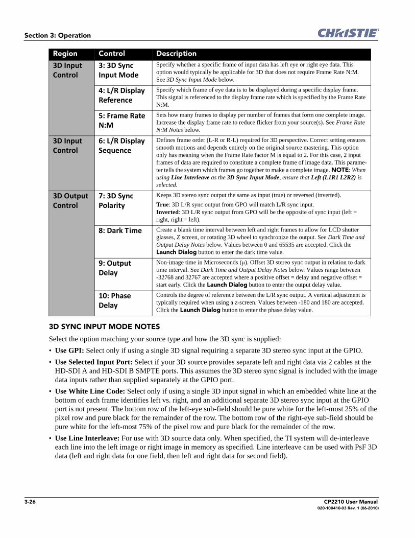
3-26 CP2210 User Manual020-100410-03 Rev. 1 (06-2010)
Section 3: Operation
3D SYNC INPUT MODE NOTES
Select the option matching your source type and how the 3D sync is supplied:
• Use GPI: Select only if using a single 3D signal requiring a separate 3D stereo sync input at the GPIO.
• Use Selected Input Port: Select if your 3D source provides separate left and right data via 2 cables at the HD-SDI A and HD-SDI B SMPTE ports. This assumes the 3D stereo sync signal is included with the image data inputs rather than supplied separately at the GPIO port.
• Use White Line Code: Select only if using a single 3D input signal in which an embedded white line at the bottom of each frame identifies left vs. right, and an additional separate 3D stereo sync input at the GPIO port is not present. The bottom row of the left-eye sub-field should be pure white for the left-most 25% of the pixel row and pure black for the remainder of the row. The bottom row of the right-eye sub-field should be pure white for the left-most 75% of the pixel row and pure black for the remainder of the row.
• Use Line Interleave: For use with 3D source data only. When specified, the TI system will de-interleave each line into the left image or right image in memory as specified. Line interleave can be used with PsF 3D data (left and right data for one field, then left and right data for second field).
3D Input
Control
3: 3D Sync
Input Mode
Specify whether a specific frame of input data has left eye or right eye data. This option would typically be applicable for 3D that does not require Frame Rate N:M. See 3D Sync Input Mode below.
4: L/R Display
Reference
Specify which frame of eye data is to be displayed during a specific display frame. This signal is referenced to the display frame rate which is specified by the Frame Rate N:M.
5: Frame Rate
N:M
Sets how many frames to display per number of frames that form one complete image. Increase the display frame rate to reduce flicker from your source(s). See Frame Rate N:M Notes below.
3D Input
Control
6: L/R Display
Sequence
Defines frame order (L-R or R-L) required for 3D perspective. Correct setting ensures smooth motions and depends entirely on the original source mastering. This option only has meaning when the Frame Rate factor M is equal to 2. For this case, 2 input frames of data are required to constitute a complete frame of image data. This parame-ter tells the system which frames go together to make a complete image. NOTE: When using Line Interleave as the 3D Sync Input Mode, ensure that Left (L1R1 L2R2) is selected.
3D Output
Control
7: 3D Sync
Polarity
Keeps 3D stereo sync output the same as input (true) or reversed (inverted).
True: 3D L/R sync output from GPO will match L/R sync input. Inverted: 3D L/R sync output from GPO will be the opposite of sync input (left = right, right = left).
8: Dark Time Create a blank time interval between left and right frames to allow for LCD shutter glasses, Z screen, or rotating 3D wheel to synchronize the output. See Dark Time and Output Delay Notes below. Values between 0 and 65535 are accepted. Click the Launch Dialog button to enter the dark time value.
9: Output
Delay
Non-image time in Microseconds (µ). Offset 3D stereo sync output in relation to dark time interval. See Dark Time and Output Delay Notes below. Values range between -32768 and 32767 are accepted where a positive offset = delay and negative offset = start early. Click the Launch Dialog button to enter the output delay value.
10: Phase
Delay
Controls the degree of reference between the L/R sync output. A vertical adjustment is typically required when using a z-screen. Values between -180 and 180 are accepted. Click the Launch Dialog button to enter the phase delay value.
Region Control Description

Section 3: Operation
CP2210 User Manual 3-27020-100410-03 Rev. 1 (06-2010)
FRAME RATE N:M NOTES
These N:M ratios define how many frames to display per number of frames that form one complete image. For all 3D use, the denominator is 2, indicating that two frames (left and right) are combined into every complete display frame. For non-3D, it is 1 frame. Set to the highest rate possible without image cropping.
DARK TIME and OUTPUT DELAY NOTES
The dark time between incoming L/R frames provides a brief interval of non-image time (in microseconds) for your switching device (such as shutters in glasses) to complete its switch. When this interval is properly set and exactly suits the speed of your device, neither eye sees image data intended for the other eye. This helps to prevent color artifacts and ghosting while ensuring that each eye sees all intended data.
The output delay setting shifts the 3D sync in relation to the Dark Time interval, starting each frame slightly earlier (-) or later (+). Adjust only as necessary—too much offset can cause “bleed-through” where each eye sees some data that is intended for the other, or causes color cropping since some DMD sequences may be clipped.
4:2 = 4 frames displayed
2 frames per image
EXAMPLE
Figure 3-18 Examples of Frame Rate N:M
5 frames, 2 sources:(48 Hz x 2.5)
6 frames, 2 sources:(48 Hz x 3)
5:2 6:2
120 Hz 144 Hz
A A AB B B
4 frames, 2 sources(48 Hz x 2)
4:2
96 Hz
24 Hz 24 Hz 24 Hz24 Hz 24 Hz 24 Hz
48 Hz 48 Hz 48 Hz
NOTE: Not for 2048 x 1080

3-28 CP2210 User Manual020-100410-03 Rev. 1 (06-2010)
Section 3: Operation
3.5.7 Advanced Setup Window
Required permission level - Advanced, Admin , or Service.
The Advanced Setup windows consist of 8 windows (9 if ILS is installed) that enable users to define numerous operating parameters such as working with lamp settings and adjusting the lens position. It also offers a broad range of options used primarily for defining how the projector responds to incoming sources in the given environment when setting up the source, screen, MCGD, and TCGD files. Since these options are saved to files, all Advanced Setup windows, with the exception of the Lamp History, LampLOC™ Setup, and Lens Setup windows, share common features to save and revert changes to the specific window files.
Table 3.15 Functionality in Advanced Setup Windows
Control Description
1: Current File In the Current File list, select a file for which to modify the settings. This option is only available in the Lamp Power / LiteLOC™ Setup, ILS Setup, Source File Setup, Screen File Setup, MCGD File Setup and TCGD File Setup windows. When changes are saved to the current file, this affects ALL channels using this file.
Lamp Power / LiteLOC™ Setup (Channel Setup: Config 1: Lamp File) *
ILS Setup (Channel Setup: Config 1: ILS File) *
Source File Setup (Channel Setup: Config 1: Source File)
Screen File Setup (Channel Setup: Config 1: Screen File)
MCGD File Setup (Channel Setup: Config 2: Measured Color)
TCGD File Setup (Channel Setup: Config 2: Target Color)
Figure 3-19 Functionality in Advanced Setup Windows
1 2 3 4

Section 3: Operation
CP2210 User Manual 3-29020-100410-03 Rev. 1 (06-2010)
* You can also edit these options in a dialog that launches from the Channel Setup: Config 1 window.
Advanced Setup: Lamp Power / LiteLOC™ Setup Window
LiteLOC™ is a lamp power control algorithm, which maintains a constant brightness as long as possible for the lamp by adjusting the power. As the lamp dims, over time the power level is increased and the red bar rises to keep the same brightness that was initially set. You can also set a precise power level for the lamp. A read-only area on the screen displays lamp performance details. The side bar graph represents the current light output and, if LiteLOC™ is enabled, a heavy line shows the chosen LiteLOC™ setting.
2: Save As Displays a dialog to enter a new configuration name and saves the current on-screen settings to this file.
3: Save Saves the current configuration with the on-screen settings. Important! If you wish to save your set-tings to a new screen file, make sure to edit the screen file name before you save, otherwise, you will overwrite the settings of the loaded screen file. Clicking the Revert button will not cancel a Save.
4: Revert Cancels new (unsaved) screen settings and reloads the settings for this file.
Control Description
Figure 3-20 Advanced Setup: Lamp Power / LiteLOC™ Setup Window
1
2
3
4
5
6 LiteLOC™
Target
Light
Intensity

3-30 CP2210 User Manual020-100410-03 Rev. 1 (06-2010)
Section 3: Operation
Table 3.16 Advanced Setup: Lamp Power / LiteLOC™ Setup
Table 3.17 Minimum and Maximum Lamp Power by Lamp Type
Christie provides a wide lamp power range to give flexibility in meeting different exhibition configurations. However, older lamps may not always strike at the lowest power settings. For more details, see Section 6 Specifications. For more information on setting lamp power, refer to 3.6.3 Adjusting Lamp Power, on page 3-75.
While it is common recommended practice in cinemas to run lamps only within their specified current ranges, we allow for an adjustment on the power supplies that allow operation of the lamps much lower than their specified wattage and up to 10% above. This is done for 2 reasons. Under-current operation is sometimes needed in systems that are normally operating both 2D and 3D operational modes and for 2D presentations. While there can be ignition problems if the current is dramatically lower than the specification, such problems don’t develop until the lamp has aged significantly. Over-current operation is used for LampLOC™ purposes. As a lamp ages, the voltage decreases. This allows for higher current to be used during the latter part of a lamp’s life and therefore extend the usability of the lamp.
Region Control Description
Manual Power
Adjust
1: Power % Indicates the percentage of power to supply to the lamp and automatically over-rides the LiteLOC™ setting that may be in effect. Refer to Table 3.17 for the valid Lamp Power ranges for specific lamp types. Adjusting the Lamp Power % causes the bar graph to rise or fall as lamp power increases or decreases. The LiteLOC™ red line and Lamp Status values will not change unless the Set Target button is clicked. This defines a new LiteLOC™ setting and selects the Enable LiteLOC™
check box. Lamp Power % is enabled only when the Enable LiteLOC™ check box is clear.
LiteLOC™ 2: Enable
LiteLOC™
Select the Enable LiteLOC™ check box to use LiteLOC™ for the current chan-nel. When LiteLOC™ is enabled, the last saved target value is used.
3: Light Meter
- Set Target
Clicking the Set Target button automatically enables LiteLOC™ (Enable LiteLOC™ check box selected) and maintains the current brightness level (shown in the Lamp Status region) as long as possible. Arbitrary units-of-mea-sure shown in the text region to the right of the Set Target button, not lumens or fL.
Lamp Status 4: Amps,
Volts, Watts,
~FL, Hours
Lamp current in amperes, lamp voltage in volts, lamp power in watts, approximate Foot Lamberts reading on the light sensor (assuming a calibration was per-formed), and hours on current lamp. These read-only values are updated automat-ically from the projector.
Intensity 5: Text Region Shows the current light sensor reading in arbitrary units-of -measure and does not represent actual lumens or fL. This read-only value is updated automatically from the projector.
6: Light Bar This visual representation of the projector’s light sensor indicates the current light intensity (vertical bar) and LiteLOC™ target (red horizontal line). The LiteLOC™ target updates automatically by moving the bar up or down based on the amount of light measured by the projector light sensor. The limits are self adjusting, so the absolute scale is not important.
Lamp Type Lamp Size Min Lamp Power Max Lamp Power
CXL-14M 1.4 kW 1000W (71.4)% 1600W (114.3%)
CDXL-18SD 1.8 kW 1000W (55.5%) 1900W (105%)
CDXL-20SD 2 kW 1000W (50%) 2100W (105%)

Section 3: Operation
CP2210 User Manual 3-31020-100410-03 Rev. 1 (06-2010)
Advanced Setup: Lamp History Window
The Advanced Setup: Lamp History window displays a read-only list of the previous and current lamps used by the projector. Once a lamp has been added, it can not be removed. When adding a new lamp, a separate dialog displays with editing boxes to record the new lamp type, serial number and the number of hours already logged on the lamp, if any. IMPORTANT! Ensure the projector is in full power ON mode when adding a new lamp. If done in stand-by mode, lamp information may be lost.
Table 3.18 Advanced Setup: Lamp History Window
Control Description
Date The date the lamp was installed. NOTE: Ensure TPC date and time are correctly set to automatically record the lamp change date properly.
Lamp Type The lamp type.
Serial Number The lamp serial number.
Hours The number of hours logged on the lamp.
Expiry Hours The recorded number of hours the lamp will expire.
Rotated States if the lamp has been rotated or not.
Reason The reason for changing the lamp.
Add Lamp Click the Add Lamp button to launch the Add Lamp window. See Add Lamp Window, on page 3-33.
Figure 3-21 Advanced Setup: Lamp History Window

3-32 CP2210 User Manual020-100410-03 Rev. 1 (06-2010)
Section 3: Operation
Add Lamp Window
Table 3.19 Advanced Setup: Add Lamp Window
Acknowledge
Lamp Rotation
Click to acknowledges when a lamp has been rotated.
Control Description
Type In the Type list, select the lamp type.
Serial Number In the Serial Number box, click the Launch Dialog button to enter the serial number of the new lamp. A serial number can be up to 128 alpha-numeric characters.
Reason for
Change
In the Reason for Change list, select a preset reason as to why you are installing this lamp.
Lamp Expiry In the Lamp Expiry box, click the Launch Dialog button to enter the number of hours in which the lamp will expire. The default value is 1200 hours for all lamps.
Hours Used In the Hours Used box, click the Launch Dialog button to enter the number of hours on the lamp. The value defaults to zero assuming a new lamp is being installed. If a used lamp is being inserted, enter the number of hours already on the lamp.
Control Description
Figure 3-22 Advanced Setup: Add Lamp Window

Section 3: Operation
CP2210 User Manual 3-33020-100410-03 Rev. 1 (06-2010)
Advanced Setup: LampLOC™ Setup Window
LampLOC™ buttons activate motors that reposition the bulb in the projector for optimized light output. Click the Do Auto button (recommended) to perform LampLOC™ or the individual buttons. NOTES: 1) The lamp must be ON before beginning LampLOC™. If it is turned off during a re-positioning, the bulb will return to its former position. 2) The douser opens and remains non-functional during a LampLOC™ adjustment. 3) For optimized performance during long term operation of the lamp, it may be beneficial to run LampLOC™ every month or two to improve lamp performance during lamp electrode burn back.
Table 3.20 Advanced Setup: LampLOC™ Setup Window
Region Control Description
1: Lamp
Position
Left/Right
Up/Down
In/Out
Arrow
Buttons
Manually moves lamp position in the X axis (left/ right for horizontal movement), Y axis (up/down for vertical movement), and Z axis (in/out for lamp axial axis move-ment). The current position of the lamp displays in cartesian coordinates. A single click corresponds to a single integer increment/decrement. Adjust one short click at a time, several longer clicks, or hold the button for an accelerated movement. There are projec-tor hardware specific limits, beyond which the lamp position will no longer move. These limits are to be defined during implementation.
2: Intensity Value Shows the current light sensor reading in arbitrary units-of -measure and does not rep-resent actual lumens or fL. This read-only value is updated automatically from the pro-jector.
Light Bar This visual representation of the projector’s light sensor indicates the current light intensity (vertical bar) and LiteLOC™ target (red horizontal line). The LiteLOC™ target updates automatically by moving the bar up or down based on the amount of light mea-sured by the projector light sensor. The limits are self adjusting, so the absolute scale is not important.
Figure 3-23 Advanced Setup: LampLOC™ Setup Window
1
2
3
LiteLOC™
Target
Light
Intensity

3-34 CP2210 User Manual020-100410-03 Rev. 1 (06-2010)
Section 3: Operation
Advanced Setup: ILS File Setup Window
Hazardous moving parts. Keep fingers and other body parts away. Remotely operated motors may start to spin without warning. Keep clear of rotating parts and avoid long hair, jewelry, and
loose clothing exposure to the knobs during manual adjustment.
The Intelligent Lens System (ILS) automates the process of adjusting the Focus, Horizontal (X) and Vertical (Y) Offset, and Zoom of the lens using a motorized lens mount. When enabled (Enable Automatic ILS check box in the Advanced Setup: Lens Setup window is selected), this window is used to modify the Intelligent Lens System (ILS) settings of ILS files. Any adjustments made to an ILS file will affect every channel that uses the file. You can adjust the focus, offset, or zoom using short, quick presses to advance the motors only a small step, slightly longer presses to advance more steps at a time, or hold the button for an accelerated movement. Experiment to get the feel. Reversing direction will cause a normal and deliberate overshoot and correction to take out any backlash in the precision mechanism for more precise results. Position values on the window will change in real-time. NOTE: If the Enable Automatic ILS check box on the Advanced Setup: Lens Setup window is not selected, a warning will display when trying to access the ILS File Setup window. Upon acknowledging the message, the options in the ILS File Setup window will be disabled (greyed).
3: Auto
LampLOC™
Do Auto Starts the auto LampLOC™ calibration procedure, which adjusts the lamp position until the highest light reading is obtained from the light sensor. Displays the LampLOC™ progress bar and Cancel Auto button.
Display Full
Screen
White
Test Pattern
Select to temporarily display a full screen white test pattern for the duration of the LampLOC™ adjustment. The previous display resumes when the LampLOC™ proce-dure is complete or the check box is cleared. Although it is not necessary to display a white test screen, it is often useful to visually monitor the motor action to assure the system is optimizing properly.
Auto
LampLOC™
Progress
Bar
Shows the current LampLOC™ procedure completion status when the Do Auto button is clicked. When status is finished, this bar and the Cancel Auto button become hid-den again.
Cancel Auto When the Cancel Auto button is clicked, the current LampLOC™ procedure is can-celled. The progress bar and Cancel Auto button will become hidden again.
Region Control Description
WARNING

Section 3: Operation
CP2210 User Manual 3-35020-100410-03 Rev. 1 (06-2010)
Table 3.21 ILS File Setup Window
Control Description
Focus Adjust the focus by clicking the clockwise/counterclockwise arrow buttons. Adjust one short click at a time, several longer clicks, or hold the button for an accelerated movement. If the focus limit is reached, further clicks will have no effect on the value.
Zoom Adjusts the zoom by clicking the negative/positive magnifying glass buttons. Adjust one short click at a time, several longer clicks, or hold the button for an accelerated movement. If the zoom limit is reached, further clicks will have no effect on the value.
Offset Adjusts the offset by clicking the up/down/left/right buttons to adjust the X/Y coordinates. Adjust one short click at a time, several longer clicks, or hold the button for an accelerated move-ment. If the offset limit is reached, further clicks will have no effect on the value. Values range from 0 to an upper limit based on the source format.
Quick Reset Resets the lens to the mechanical center before moving back to the original position.
MALM Reset If present, resets the position of the MALM to the mechanical reference point. This is typically used if the MALM is bumped or manually moved.
Figure 3-24 ILS File Setup Window

3-36 CP2210 User Manual020-100410-03 Rev. 1 (06-2010)
Section 3: Operation
Advanced Setup: Lens Setup Window
The Advanced Setup: Lens Setup window allows you to setup the primary and auxiliary lenses. You can also setup the Intelligent Lens System (ILS).
Table 3.22 Advanced Setup: Lens Setup Window
Region Control Description
1: Lens Data Primary Lens In the Primary Lens list, select the type of primary lens installed on the projector.
Serial Number In the Serial Number box, click the Launch Dialog button to enter the primary lens serial number.
Auxiliary Lens In the Auxiliary Lens list, select the type of the auxiliary lens installed on the pro-jector.
Serial Number In the Serial Number box, click the Launch Dialog button to enter the auxiliary lens serial number.
Save/Revert Saves/reverts the changes made to the lens type and/or serial number(s). Exiting the window before saving will lose your changes.
2: Intelligent
Lens System
Enable
Automatic ILS
When selected, the lens will automatically move to the position associated with the channel and all adjustments made to the focus, zoom, and offsets in the ILS File Setup window will overwrite the saved ILS values. For more information, see Advanced Setup: ILS File Setup Window, on page 3-35. When clear, adjustments can only be made from the ILS Adjust window launched from the Main panel. These adjustments are preserved when a channel changes, but are never written to an ILS file.
Figure 3-25 Advanced Setup: Lens Setup Window
1
2 3

Section 3: Operation
CP2210 User Manual 3-37020-100410-03 Rev. 1 (06-2010)
2: Intelligent
Lens System
Reset on
Startup
Select the Reset on Startup check box for the ILS to calibrate the lens when the projector starts up via the wall circuit or clicking the Power ON button. NOTE: This is not normally required. It is made available for cases where repeatability issues don’t go away by powering down the projector.
Quick Reset Click the Quick Reset button to perform a quick reset on the ILS. The lens will return to the manual position when complete. A quick reset allows the system to detect precise center positions so previous channel presets work as expected, even after manual adjustments.
Full
Calibration
Click the Full Calibration button to perform a full ILS calibration. The lens will return to the manual position when complete. A full calibration detects full range or movements on a new lens and also resets center detect positions.
3: Motorized
Auxiliary Lens
Mount
Calibration
(Optional)
MALM
Installed
Select the MALM Installed check box when a MALM is installed onto the pro-jector.
MALM Reset Resets the position of the MALM to the mechanical reference point. This is typi-cally used if the MALM is bumped or manually moved.
In Click the up/down buttons to increment the MALM to the right/left. Adjust one short click at a time, several longer clicks, or hold the button for accelerated move-ment. Alternatively, click the Launch Dialog button to the right of the IN text region to enter a value. If the MALM is in the OUT position (right), the MALM will first move to the IN position (left) before the incremental adjustments begin. You can also move the MALM to the IN position by clicking the Aux Lens In button on the Main panel. Refer to 3.3 Main Panel, on page 3-3.
Out Click the up/down buttons to increment the MALM to the right/left. Adjust one short click at a time, several longer clicks, or hold the button for accelerated move-ment. Alternatively, click the Launch Dialog button to the right of the OUT text region to enter a value. If the MALM is in the IN position (position), the MALM will first move to the OUT position (right) before the incremental adjustments begin. You can also move the MALM to the OUT position by clicking the Aux
Lens Out button on the Main panel. Refer to 3.3 Main Panel, on page 3-3.
Region Control Description

3-38 CP2210 User Manual020-100410-03 Rev. 1 (06-2010)
Section 3: Operation
Advanced Setup: Source File Setup Window
Incoming sources can vary widely in their pixel resolution and original aspect ratio. The projector must be able to respond to the myriad of possible combinations, projecting full images of the desired size, content, and proportion in every case. This consistency is achieved by creating a variety of source files in projector memory, each of which indicates the following for the projector:
• Incoming resolution (i.e., #pixels across, #pixels top-to-bottom)
• Desired offset (i.e., amount of data to discard. Rare.)
• Desired aspect ratio (i.e., the original display format to be recovered)
In rare cases, the content distributor may include this source information as part of a pre-defined Projector Configuration File (PCF) applied by using the PCF in the projector. Alternatively these variables can be defined in the Advanced Setup: Source File Setup window. With a good collection of assorted source files available in memory, the proper file can then be quickly chosen from within the Channel Setup: Config 1 window for implementation in the projector whenever a matching input signal is encountered. NOTE: For any source, the projector relies on Source File settings as well as Screen File settings. Refer to the Advanced Setup: Screen File Setup Window, on page 3-41.
Figure 3-26 Advanced Setup: Source File Setup Window
1 2
3

Section 3: Operation
CP2210 User Manual 3-39020-100410-03 Rev. 1 (06-2010)
Table 3.23 Advanced Setup: Source File Setup Window
RESOLUTION NOTES
To capture (or process) all of the incoming data, enter the full resolution of the incoming source material or leave at “0” (default). Regardless of whether or not the original material has been “squeezed” for use with an anamorphic lens, enter the current incoming resolution. Depending on how the source was formatted before distribution, this may not necessarily match the resolution of the projector or the original filmed material. For example, an original 2048 x 1080 native source supplied pre-squeezed as 1920 x 1080 requires a source file indicating this incoming 1920 x 1080 resolution. NOTE: Flat aspect ratio D-Cinema content normally is mastered as 1998 x 1080 pixels. Scope is mastered as 2048 x 858 pixels. In these cases, the source file should be set to 1998 x 1080 or 2048 x 858 respectively.
To capture only a portion of an incoming image full-screen—like a “zoom” function—, enter the approximate horizontal width and vertical height defining the area of the image to zoom in on. The projector automatically scales a center area of this size so that it fills the projector’s 2048 x 1080 display. The remaining data is ignored. It may be necessary to experiment with the values to accurately zoom in on a precise area. Offset must also be defined to zoom in on an area other than the center.
OFFSET NOTES
Offsetting an image is achieved by defining how much horizontal width and vertical height to discard. Offset coordinates can be particularly useful when zooming in on a portion of the image—they establish the top left corner location of the zoom area, with resolution determining the size of the area. Leave offset at 0 to process all incoming data or to zoom in at the center of the image.
• A positive “x/y” value - discards image data from top and/or left.• A negative “x/y” value - discards image data from bottom and/or right.
ASPECT RATIO NOTES
In the event your source material is pre-scaled or compressed, select the Custom option button and enter the desired aspect ratio. Adding the 1.25x anamorphic lens widens a “squeezed” image back to its original “scope” aspect ratio. For sources that are not pre-squeezed, aspect ratio can be left at 0 (nothing selected in window).
Control Description
1: Resolution Record the X/Y resolution of your incoming signal, such as 2048 (X) and 858 (Y) or 1920 (X) and 1080 (Y). The resolution must match the incoming signal format (assuming you want to display the entire image) and may differ from the original resolution that you want to recover. See Resolution Notes below. Click the up/down buttons to increment/decrement the X/Y resolution within the defined limits. Adjust one short click at a time, several longer clicks, or hold the button for an accelerated movement. Alternatively, click the Launch Dialog button to the right of the X/Y text regions to enter these values. The allowable X range is 0 to 4096 pixels and Y range of 0 to 2160 pixels.
2: Offset Record how much incoming data you wish to discard, essentially delaying the “starting” point for processing. Leave at 0 to process all available data. See Offset Notes below. Click the up/down buttons to increment/dec-rement the X/Y offset within the defined limits. Adjust one short click at a time, several longer clicks, or hold the button for an accelerated movement. Alternatively, click the Launch Dialog button to the right of the X/Y text regions to enter these values. The allowable X range is 0 to 4095 pixels and Y range of 0 to 2160 pixels.
3: Aspect
Ratio
Select an aspect ratio (width-to-height proportion) of the original cinema format you are trying to recover, usually 1.85 or 2.39. See Aspect Ratio Notes below. To enter a custom value, select the Custom option button and click the Launch Dialog button in the Custom box. A custom offset value can range from 0 to 7.99.
3:2
4:3
16:9
1.85:1
2.39:1 Figure 3-27 Aspect Ratio

3-40 CP2210 User Manual020-100410-03 Rev. 1 (06-2010)
Section 3: Operation
Advanced Setup: Screen File Setup Window
The Advanced: Screen File Setup window defines the portion of the projector’s display panel you wish to use and any cropping that is needed to disguise possible keystoning or other geometric aberrations. Once saved, a screen file can be used with any incoming source as desired. The default source files are called Flat and Scope, which must be defined before you can select them in the Channel Setup: Config 1 window. Screen data is not included in a PCF and is independent of source settings. Consider screen files as convenient compensations for physical limitations in the environment. You will typically need one or two screen files per site.
Table 3.24 Advanced Setup: Screen File Setup Window
Control Description
Letter Box Select the Letter Box check box to ensure that all image data is displayed and its aspect ratio is maintained. See Letter Box Notes below.
Lens Factor Define the anamorphic lens needed to stretch an image horizontally. In the Lens Factor list, click the Launch Dialog button to enter the new lens factor where values can range from 0.00 to 7.99. Leave at 1 (default) if no anamorphic lens is needed.
Presentation Define the projector’s display area to incoming data, i.e. the display size and location. By default, the projector uses its complete display area (a full 2048 x 1080 panel). See Presentation Notes below. To adjust the top, left presentation point, select the top left option button and then adjust the X/Y values using one of the two options:
• adjust the sliders to increase/decrease the value. Using the sliders moves the projected display area in real-time. • click the Launch Dialog button in the Presentation X/Y lists to enter a value using the on-screen keyboard.
Repeat this action after clicking the bottom right option button.
Figure 3-28 Advanced Setup: Screen File Setup Window

Section 3: Operation
CP2210 User Manual 3-41020-100410-03 Rev. 1 (06-2010)
PRESENTATION NOTES
Presentation points define what region of the projector’s available display area responds to incoming data. By default, the projector will use its complete display area, scaling the incoming data as necessary. If for some reason you want to limit the display area, enter the desired “upper left” and “lower right” presentation coordinates. To edit the upper left coordinates, select the top left option button and then adjust the X/Y values using either the sliders to increase/decrease the value or click the Launch Dialog button in the Presentation X/Y boxes to launch the on-screen keyboard. (Figure 3-29). Using the sliders moves the projected display area in real-time. You can define a smaller rectangular area in which the left and right top corners will always share the same “y” coordinate (y = 175 in Figure 3-29), as will the left and right bottom corners (y = 951 in Figure 3-29). The top and bottom left corners will share the same “x” coordinate (x = 80 in Figure 3-29), as will the top and bottom right corners (x = 1120 in Figure 3-29), thus top right and bottom left coordinates are not available to define the area. Incoming data will then automatically resize to fill the reduced rectangular area defined by the new coordinates, and any display pixels outside of this area remain off (black).
CROPPING NOTES
Cropping is the digital equivalent of filing aperture plates in a film projector to perfect the image “square-ness”. For example, if the bottom of the image appears slightly wider than the top, select the bottom left or bottom right option button and then adjust the X/Y coordinates using either the sliders to increase/decrease the value or click the Launch Dialog button in the Cropping X/Y boxes to launch the on-screen keyboard. The intent is to crop or “bring in” the corner(s) of the image slightly. NOTE: This is cropping, not electronic keystoned adjustment. In most cases, cropping assumes that the entire projector display area is in use, thus the coordinates initially define pixel locations on the projector’s 2048 x 1080 display area. Images that are significantly smaller in format may actually lie beyond the range of one or more cropping adjustments, thus you will not see evidence of cropping on the edges.
Cropping Cropping hides unwanted data, i.e. if the image appears keystoned. See Cropping Notes below.
To adjust the top, left cropping point, select the top left option button and then adjust the X/Y val-ues using one of the two options:
• adjust the sliders to increase/decrease the value. Using the sliders moves the projected display area in real-time. • click the Launch Dialog button in the Cropping X/Y lists to enter a value using the on-screen keyboard.
Repeat this action after clicking the top right; bottom left; and bottom right option buttons. When the top middle, right middle, bottom middle, left middle option buttons are selected, adjust the Curve value using either the slider or on-screen keyboard.
Control Description
Figure 3-29 Presentation Example

3-42 CP2210 User Manual020-100410-03 Rev. 1 (06-2010)
Section 3: Operation
When projecting onto a curved screen, a bowed image sometimes results. To correct these bowed edges so that the image appears properly in the display, select the left middle option button and then adjust the Curve value using either the sliders to increase the value or click the Launch Dialog button in the Curve box to launch the on-screen keyboard and type a new value. Repeat this step after selecting the middle right option button. This turns off or drops pixels outside of the cropped region.
LETTER BOX NOTES
Use Letter Box for virtually all normal operation. It ensures that all incoming data will display within your defined presentation area and nothing will be discarded. If desired, any “black bars” (unused pixels) could then be cropped off using the cropping control. Clearing the Letter Box check box also fills the defined presentation area, any extra data beyond this area—whether top-and-bottom or left-and- right—will be discarded. NOTE: Select the Letter Box check box for all cinema presentations.
Theatre Screen
80,175 1120,175
1120,95180,951
x=80y=200
x=1000y=200
x=1000y=951
Before After
Cropping Settings for top, left corner of screen
Figure 3-30 Cropping Example
Figure 3-31 Bow Cropping Example
80,175 1120,175
1120,95180,951
x=130y=175
Curve=-50
x=1070y=175
x=1070y=951
x=130y=951
Curve=50
Crop PointsBefore
Dropped pixels
Dropped
pixels
Unused pixels
Complete imageIncomplete image
Letter Box Letter Box
Figure 3-32 Letter Box Example

Section 3: Operation
CP2210 User Manual 3-43020-100410-03 Rev. 1 (06-2010)
Advanced Setup: MCGD File Setup Window
The MCGD File Setup window allows you to record measurements for currently projected “uncorrected” colors. Recording the projector’s uncorrected color performance is typically completed as a final step after installation as a calibration. By default, the projector will use this MCGD to calculate and implement precise processing modifications needed to achieve any target color gamut on-screen, essentially compensating for the type of port window, screen, lens, light output, ambient light and other current environmental factors influencing on-screen colors. If the environment degrades or changes (such as if an anamorphic lens is swapped on and off) or if an internal optical module is replaced, create one or more new MCGD files. To use an MCGD file as the reference file for target color processing (such as with a certain source and/or lens), select it in the Channel Setup: Config 2 window. NOTE: If the Measured Color option in the Channel Setup: Config 2 window shows a warning symbol next to the option, the MCGD File Setup still needs to be defined. This file must be defined before you can select it.
Table 3.25 Advanced Setup: MCGD File Setup Window
Control Description
1: Gamut Visual
Control
Click a colour option button to enable the colour test pattern on the screen. See To Record MCGD Color Settings below.
2: Off Button Turns off the displayed color and returns the projector to content play.
3: Revert Button With the cursor in a text box, click the Revert button to revert to the previously saved value.
4: Back Button Click the Back button to delete the entry before the cursor one character at a time.
5: Enter Button Click the Enter button to accept the current entry and advance the cursor to the next text region.
Figure 3-33 Advanced Setup: MCGD File Setup Window
1
23 4
5

3-44 CP2210 User Manual020-100410-03 Rev. 1 (06-2010)
Section 3: Operation
To Record MCGD Color Settings
For this one-time procedure for 2D displays, measure the initial “native” (i.e., uncorrected) x/y color coordinates for each color (Red, Green, Blue, and White) at the screen using a color meter. These values represent the current viewable primary colors and collectively defines the raw color performance or reference point for the projector in the current environment. A similar file needs to be defined for 3D channels with the 3D system installed and passive glasses worn. To define the MCGD:
1. On the TPC, ensure the Current Measured (MCGD) File is Onsite in the Advanced Setup: MCGD File Setup window.
2. Click a color option button to display the full-field color. Each color option button activates the corresponding full-field YCbCr test pattern of this native color so that measurements can be taken.
3. Measure the coordinates at the screen using a color meter.
4. On the TPC, record the values in the nearby x and y text boxes for the selected color.
5. Repeat Steps 2 - 4 for each color.
6. After all colors have been measured and recorded, select the Off option button to leave the special test pattern mode and then click the Save button. To cancel changes and return to the previous MCGD coordinates, leave the window without saving or click the Revert button next to the Save button.
Advanced Setup: TCGD File Setup Window
The TCGD File Setup window allows you to modify or create custom Target Color Gamut Data (TCGD) files for new color gamut performance and set how closely you want to match the target white. NOTE: Industry-defined TCG standards, such as P7v2 and others are write-protected and cannot be changed. Modifications to such a target must be saved under a new TCGD file name. Once you have created a new TCGD file, it appears in the Channel Setup: Config 2 window as Target Color where it can be selected for use in the display.
Figure 3-34 Advanced Setup: TCGD File Setup Window
2
13
5
4

Section 3: Operation
CP2210 User Manual 3-45020-100410-03 Rev. 1 (06-2010)
Table 3.26 Advanced Setup: TCGD File Setup Window
* Alter the values using one of the two options:
• click the up/down buttons to increment/decrement the coordinates/value. Adjust one short click at a time, several longer clicks, or hold the button for an accelerated movement.
• click the Launch Dialog button to the right of the x/y text regions to enter a value using the on-screen keyboard.
TCGD NOTES
You can create a new custom target by defining different coordinates for one or more TCGD colors or simply by changing the tolerance state and then saving as a new TCGD file. For most applications, TCGD values are used simply to verify that displayed colors actually do match the standard, i.e., you can measure each color at the screen and compare its coordinates to those appearing in the TCGD fields to confirm that the projected colors are accurate. For special applications in which you want to create a unique target color standard, enter new TCGD coordinates as desired and then click the Save As button to save as a new TCGD file.
To Record TCGD Color Settings
For each color, record the native “uncorrected” x/y color coordinates measured at the screen. These values represent the currently viewable primary colors, and collectively define the raw color performance “reference point” for this projector in the current environment. Each color option button activates the corresponding full-field YCbCr test pattern of this native color so that measurements can be taken. For example, to measure the red coordinates, click the Red option button to change the screen display to full-field red and measure coordinates at the screen. Repeat for each color, and record them in the x/y text boxes. After all colors have been measured and recorded, click the Save button. To cancel changes and return to the previous TCGD coordinates, leave the window without saving or click the Revert button next to the Save button.
Control Description
1: Use White
Clip *
Select the Use White Clip check box when playing back content encoded with the DCI XYZ color space. This will help bring the chromaticity of white within range with the projector without sacrificing output brightness or contrast. To adjust the actual white clip limit, select the Use White Clip check box and then select the radio button below the Use White Clip check box. Next, adjust the x/y values accordingly.
2: Gamut
Visual
Control *
The Target (TCGD) color fields show the corresponding x/y color coordinates defined for the current target color gamut in use. See TCGD Notes below. To adjust the value of the x/y color coordinates, click a color option button to display the x/y values for the selected color, and then change the value based on the measurements taken from the screen. The selected color displays above x text box.
3: Gain * Gain indicates the luminance (a.k.a. brightness or intensity) of each color as compared to full-on white, ranging from 0 (0%) to 1 (100%). You may want to modify one or more gain values to precisely match color levels in other adjacent displays or to accommodate a studio’s internal color management tech-nique. Gain would rarely if ever be adjusted for theatre use.
4: Display
Test Pattern
Shows a test pattern when the color changes. Select the Display Test Pattern check box and then select a color option button in the Gamut Visual Control region.
5: White
Tolerance *
The chosen target for white coordinates (White XY) under Target (TCGD) may be relaxed by estab-lishing a small “tolerance box” around it. This box represents four coordinates (0-1-2-3) plotted on a 1931 CIE Chromaticity graph and may vary from TCGD to TCGD. See White Tolerance Notes below. Select the White Tolerance check box to enable the White Tolerance grid and x/y text boxes. To change the value of the x/y colour coordinates measured from the screen, select one of the four corners and then adjust the value. Values range from 0.0 to 1.0.

3-46 CP2210 User Manual020-100410-03 Rev. 1 (06-2010)
Section 3: Operation
WHITE TOLERANCE NOTES
If desired, define new tolerance coordinates for the current TCGD to increase or decrease this tolerance area or to change its shape or location. Larger boxes relax the tolerance reducing the loss of light caused by precise matching. If the projector’s whites must precisely match the target white point defined for the current TCGD (typical for telecine use), ensure the White Tolerance check box is clear. If this match can be anywhere within the tolerance box (typical for theatre use), click the White Tolerance check box.
The White Tolerance check box status is saved with the TCGD. Keep in mind that some light is usually discarded for an exact match, resulting in a dimmer image. It is recommended that you enable the tolerance box for all applications requiring maximum brightness, such as in theatres. Do not enable the White Tolerance check box if exact color performance is more crucial than overall image brightness, such as in telecine applications.
3.5.8 Administrator Setup Window
Required permission level - Administrator or Service.
Administrator Setup: Preferred Channel Setup Window
The Preferred Channel Setup window enables the management and organization of all available channels. There are 64 pre-defined channels in total where nine channels display directly on the Main panel of the TPC. This window allows you to select and organize these nine channels.
Figure 3-35 Administrator Setup: Preferred Channel Setup Window
21
3

Section 3: Operation
CP2210 User Manual 3-47020-100410-03 Rev. 1 (06-2010)
Table 3.27 Administrator Setup: Preferred Channel Selection Window
To Add a Channel
To add a channel button, drag the button from the All Channels region (left side of graphic in Figure 3-35) and place it on top of a button in the Selected Channel Buttons region (right side of graphic in Figure 3-35). Buttons in this region can be dragged on top of one another to switch button locations.
To Delete a Channel
To remove a channel from the Selected Channel Buttons region (right side of graphic in Figure 3-35), drag and drop the channel on top of the trash can. This defines an empty channel on the Main panel. Channels dragged to the trash can cannot be retrieved. You need to add the channel from the All Channels region once again.
Administrator Setup: Preferred Test Pattern Setup Window
The Preferred Test Pattern Setup window enables the management and organization of all available test patterns. Patterns in the User Selected region (right side of graphic in Figure 3-36) are available to you via the Test Pattern button on the Main panel.
Control Description
1: All Channels An alphabetical list of all 64 channels to choose from.
2: Selected
Channel Buttons
A list of the nine buttons that display on the Main panel of the TPC. Buttons in this region can be dragged on top of one another to switch button locations.
3: Trash Can Used to delete a channel from the Selected Channel Buttons region.
Figure 3-36 Administrator Setup: Preferred Test Pattern Setup Window
21
3 4 5
6

3-48 CP2210 User Manual020-100410-03 Rev. 1 (06-2010)
Section 3: Operation
Table 3.28 Administrator Setup: Preferred Test Pattern Setup Window
To Add a Test Pattern
To add a test pattern, drag a test pattern from the Unselected Patterns region (left side of graphic in Figure 3-36) and drop it in the User Selected region (right side of graphic in Figure 3-36). If the Test Pattern is added, it will be removed from the Unselected Patterns region.
To Delete a Test Pattern
To remove a test pattern from the User Selected region, drag and drop the test pattern on top of the trash can. Test Patterns dragged to the trash can cannot be retrieved. You need to add the test pattern from the Unselected Patterns region once again.
Control Description
1: Unselected
Patterns
An alphabetical list of all available test patterns for display by the projector for you to choose from. If a pattern is dragged to the User Selected region, it will be removed from this list.
2: User
Selected
A list of test patterns specifically selected by the user. This list is displayed when you click the Test Pattern button on the Main panel.
3: Test Pattern
Off
The Test Pattern Off button stops displaying the test pattern currently displayed by the projector.
4: Test The Test button displays the selected test pattern on-screen regardless if the selected test pattern is in the Unselected Patterns region (left side of graphic in Figure 3-36) or User Selected region (right side of graphic in Figure 3-36).
5: Full Screen Select the Full Screen check box to display the test pattern full screen, 2048 x 1080. If the Full Screen check box is clear, the test pattern will show in native resolution which may not fill the projec-tion area.
6: Trash Can Used to delete a test pattern from the User Selected region.

Section 3: Operation
CP2210 User Manual 3-49020-100410-03 Rev. 1 (06-2010)
Administrator Setup: Preferences Window
The Preferences window provides access to various system parameters.
Table 3.29 Administrator Setup: Preferences Window
Region Control Description
1: General Temperature Units Select whether to display the temperature displayed on the TPC win-dows in Celsius or Fahrenheit, for example, the values in the Status: Temperatures window.
Image
Orientation
Select the orientation of the image on the screen. This is for flipping the image on the screen, for example if you install a projector upside down on the ceiling and need to switch the orientation. The default is Normal Front.
Luminance Units Select to display the luminance settings displayed on the TPC windows in Foot Lamberts or Candela, for example, the Luminance value in the Status: Lamp Info window.
Language Select to display the language of the TPC user interface and online help.
2: TPC
Controls
Beep on Screen
Press
Select the Beep on Screen Press check box if you want to hear a beep every time you touch the screen.
Enable Screen Saver
/ Screen Saver Delay
Select the Enable Screen Saver check box if you want to enter screen saver mode after a specified time of no interaction. While in screen saver mode, the screen is blank and the back light is off. In the Screen Saver Delay list, select the amount of non-interaction time before entering screen saver mode.
Figure 3-37 Administrator Setup: Preferences Window
1
2
4
3

3-50 CP2210 User Manual020-100410-03 Rev. 1 (06-2010)
Section 3: Operation
3: Alarm
Triggers
Over Temperature,
Fan Failure, Lamp
Rotation, Lamp
Expiry, LD Log Warn-
ing
Select the Alarm Triggers check boxes for the conditions you want to trigger an alarm window. Interlocks, communication faults, DMD over-temperature and lamp failure are all permanent triggers. It is strongly recommended all triggers remain selected during normal operation. The Lamp Rotation alarm is triggered when the Lamp Expiry value has reached 50%. The Lamp Expiry alarm is triggered when the Lamp Expiry value that was entered when installing the lamp is reached. The LD Log Warning alarm is triggered when the Link Decrypter logs are almost full.
4: Touch-
screen
Calibration
Calibrate Screen Click the Calibrate Screen button and follow the on-screen instruc-tions to touch and hold the red dot until calibration is complete.
Region Control Description

Section 3: Operation
CP2210 User Manual 3-51020-100410-03 Rev. 1 (06-2010)
Administrator Setup: Time Setup Window
The Time Setup window allows you to change the time zone and adjust the system time by up to ±15 minutes per year.
Table 3.30 Administrator Setup: Time Setup Window
Region Control Description
1: Time
Zone
Time Zone In the Time Zone list, select your time zone.
24 Hour Time Click the 24 Hour Time check box to display the TPC time in 24-hour format. Clear the 24 Hour Time check box to display the standard 12-hour format. The default format is 12-hour.
2: Time
Adjust
Time Offset The current time is displayed on each window of the TPC. It is retrieved from the LD board and cannot be altered. The Time Offset feature allows you to adjust the system time by a maximum of ± 15 minutes (900 seconds) per year. Click the up/down buttons to increment/dec-rement the time offset value or click the Launch Dialog button to the right of the time offset text region to enter the value using the on-screen keyboard.
Apply Time
Adjustment
Click the Apply Time Adjustment button to apply the changed time settings.
Figure 3-38 Administrator Setup: Time Setup Window
1
2

3-52 CP2210 User Manual020-100410-03 Rev. 1 (06-2010)
Section 3: Operation
Administrator Setup: Communications Configuration Window
The Communications Configuration window configures the Ethernet settings, serial communication parameters, SNMP settings, and remote access settings. NOTE: Record any new settings on page 1-4 of this manual.
Table 3.31 Administrator Setup: Communications Configuration Window
Region Control Description
1: Device Name Device Assign a specific name for this device in the network. In the Device Name text box, click the Launch Dialog button to edit the device name using the on-screen keyboard.
2: Ethernet
Settings
IP Address This is a unique address assigned for a specific device and site. The first three octets of the IP address identify the network to which the device belongs; the last octet identifies the specific device.
Subnet Mask All IP addresses for a network belong to the same Net Mask (also called a Subnet Mask) as defined by the network administrator.
Gateway This is a site specific network address and is common for Ethernet Man-agement and Service Ethernet ports.
Apply Click the Apply button to implement the current Ethernet configuration settings.
3: RS-232 Settings Serial Speed
(Baud)
In the Serial Speed list, select the serial port baud rate. The default value is 9600.
Figure 3-39 Administrator Setup: Communications Configuration Window
1
2 3
4 5

Section 3: Operation
CP2210 User Manual 3-53020-100410-03 Rev. 1 (06-2010)
NOTE: Contact Christie for the SNMP V3 user ID and password.
4: SNMP Settings Enable SNMP Select the Enable SNMP check box to enable the SNMP agent. By default, the check box is clear meaning SNMP is off (no Traps sent)
SNMP V2 /
SNMP V3
Select between SNMP v2 and v3 protocol.
Management IP The SNMP management IP address where traps and notifies will be sent.
Download MIB
to USB
Click the Download MIB to USB button to launch a License Agree-ment dialog to accept or reject certain conditions before downloading the SNMP Management Information Base (MIB) file to a USB drive.
Apply Click the Apply button to launch an editable version of the management IP Control and send SNMP traps to.
5: Remote Access Serial Access In the Serial Access list, select the degree of permission to grant serial access.
Ethernet Access In the Ethernet Access list, select the degree of permission to grant Ethernet access.
Region Control Description

3-54 CP2210 User Manual020-100410-03 Rev. 1 (06-2010)
Section 3: Operation
Administrator Setup: Network Devices Window
The Network Devices window lets you view the web interface of external peripherals such as Christie ACT and the Integrated Media Block (IMB).
To Add a Network Device
1. Select a check box to the left of the Christie ACT or Integrated Media Block devices to enable the device. If you want to add a different device, in the Device Name text box, enter the device name or click the Launch Dialog button to enter the device name using the on-screen keyboard.
2. In the URL text box, enter the URL or click the Launch Dialog button to enter the URL using the on-screen keyboard.
3. Your network device is now defined. View the web interface of this device by clicking the Menu button, selecting Network Device, and then selecting your new device. Refer to 3.5.5 Network Devices, on page 3-19 for more information on defined devices.
Figure 3-40 Administrator Setup: Network Devices Window
1 2

Section 3: Operation
CP2210 User Manual 3-55020-100410-03 Rev. 1 (06-2010)
Administrator Setup: GPIO Setup Window
The GPIO Setup window allows for the configuration of both input and output GPIO functions. For GPI, the system can be configured to trigger a specific pin either on a rising or falling edge. When the configured trigger is received, the function associated with that pin will be executed. Similarly when a specified function is activated on the projector, like the switch to a channel or the lamp turning on, a specified pin can be configured to send a rising of falling edge signal.
Table 3.32 Administrator Setup: GPIO Setup Window
Region Control Description
1: Inputs
Actions
Rising Edge In the Rising Edge list, select the rising edge option which will send the signal to execute the selected function.
Falling Edge In the Falling Edge list, select the falling edge option that will execute when the selected signal is received.
2: Output
Actions
Trigger In the Trigger list, select the trigger that will be sent when the selected function is activated.
Output In the Output list, select the output that will trigger the GPO signal to be sent.
Figure 3-41 Administrator Setup: GPIO Setup Window
1 2

3-56 CP2210 User Manual020-100410-03 Rev. 1 (06-2010)
Section 3: Operation
Administrator Setup: Foot Lamberts Calibration Window
The Foot Lambert Calibration window begins a series of panels that guides you through the process to calibrate the internal light sensor to Foot Lamberts. The left column of the Foot Lamberts Calibration window shows which state you’re currently at in the calibration process. (Figure 3-42). Click the Next/Prev buttons to navigate the windows. NOTE: Do not perform a Foot Lamberts Calibration when a show is playing as this will stop the show.
Figure 3-42 Administrator Setup: Foot Lamberts Calibration Start Window

Section 3: Operation
CP2210 User Manual 3-57020-100410-03 Rev. 1 (06-2010)
Steps to Perform Foot Lamberts Calibration
1. Before starting the Foot Lamberts Calibration measurement process, ensure the lamp is ON and you have your light meter ready (Figure 3-42). Click the Next button to proceed to the Test Pattern window. If either of these two conditions are not met, the Next button will be disabled (greyed out) and will not let you proceed with the calibration.
2. In the Test Pattern window, you need to click the Activate Full White Test Pattern button before proceeding. (Figure 3-43). NOTE: This procedure will stop any content currently playing on the projector. Click the Next button to proceed to the Maximum window.
Figure 3-43 Click to Activate a Full White Test Pattern

3-58 CP2210 User Manual020-100410-03 Rev. 1 (06-2010)
Section 3: Operation
3. In the Maximum window, the projector sets the lamp to the maximum light output. Measure the screen light output at the screen with a light meter and enter the value in the Meter Reading text region by clicking the up/down buttons or clicking the Launch Dialog button to launch the on-screen keyboard to enter this value. (Figure 3-44). Values can range from 0.00 to 1000.00. In the Meter Units list, select the preferred units (Foot Lamberts or Candelas). Once complete, click the Next button to proceed to the Minimum window.
4. In the Minimum window, repeat step 3 to record the minimum light output. Values can range from 0.00 to 1000.00. Once complete, click the Next button to proceed to the Save Calibration window.
5. In the Save Calibration window, click the Save button to permanently save the configuration. Click the Next button to proceed to the Complete window.
6. The Complete window shows the success of the Foot Lamberts calibration. Click the Finish button to return to the Main panel.
Figure 3-44 Record the Meter Reading at Maximum Light Output

Section 3: Operation
CP2210 User Manual 3-59020-100410-03 Rev. 1 (06-2010)
Administrator Setup: User Accounts Window
The User Accounts window provides options for the management of users, passwords, and user access rights. Depending on your login level, you will be able to manage users having the same or fewer access rights as you.
Table 3.33 Administrator Setup: User Accounts Window
Control Description
User Name &
Permissions
A read only data grid view used to display a list of all users and their permissions.
Add Click the Add button to launch a dialog to enter the username, password and permission level for a new user. See Adding a New User below.
Edit Select a user and click the Edit button to adjust the password and permission level for the user. If the active user is of a lower permission level then the currently selected user, a warn-ing will display preventing the changes.
Delete Select a user and click the Delete button. A confirmation dialog displays.
Figure 3-45 Administrator Setup: User Accounts Window

3-60 CP2210 User Manual020-100410-03 Rev. 1 (06-2010)
Section 3: Operation
To Add a New User
1. Click the Add button to launch a dialog to enter the username, password and permission level for a new user.
2. In the Username list, click the Launch Dialog button enter the username using the on-screen keyboard. The username requires 4 - 32 characters with no numbers or special characters.
3. In the Password list, click the Launch Dialog button enter the password using the on-screen keyboard. Passwords require 4 - 32 characters with spaces, numbers, and special characters accepted.
4. Repeat step 3 for the Confirm Password list.
5. In the Permission list, select the permission level for the new user. The level can be the same or lower than the current active user. Permission levels are Operator, Advanced, Administrator, and Service in order from lowest to highest.
Figure 3-46 Add a New User Window

Section 3: Operation
CP2210 User Manual 3-61020-100410-03 Rev. 1 (06-2010)
Administrator Setup: Upgrade Window
The Upgrade window begins a series of steps to walk you through the upgrade process. You must login with Administrator or Service permissions to use the upgrade feature. The left column of the Upgrade window shows which state you’re currently at in the upgrade process. Click the Next/Prev buttons to navigate the series of steps.
Steps to Install an Upgrade Package
1. Access the Upgrade Package using ONE of the following processes:• Insert the USB drive containing the upgrade package into one the USB ports at the back of the TPC.
Open the back cover and reveal the USB ports. Navigate to the Administrator Setup: Upgrade window and click the Upload button. (Figure 3-47). This launches a file selection dialog for you to navigate and select this file. Once complete, the system automatically advances to the Extraction window and begins extracting the upgrade package.
• From an FTP client, enter the projector IP address and enter the user name and password. Once con-nected, copy the upgrade package from the FTP site to the root folder of the projector. The upgrade pack-age should display in the Available Upgrade Files region of the File Selection window. (Figure 3-47). Select the upgrade package and click the Next button to advance to the Extraction window. NOTE: After copying several upgrade packages to the root folder, an alarm will occur if the disk space becomes full. Navigate to the root folder and delete the older upgrade packages. Once removed, copy the current upgrade package again.
2. The Extraction window shows the progress of extracting, decrypting, and verifying the files. On any failure, the upgrade process will display an error dialog and then bring you back to the File Selection window. On successful extraction of the package, the upgrade process will automatically advance to the Package Details window. Once the extraction is complete, you can remove the USB drive.
3. The Package Details window shows the versions of all components installed in the projector. (Figure 3-48). Select the type of install to perform: Upgrade Different Packages Only, Force Upgrade All, or Factory Defaults Install and click the Next button to advance to the Installation window.
4. The Installation window displays the state of the upgrade progress. (Figure 3-49). On successful completion or failure of the installation, a dialog will display indicating the state of the upgrade. Click the OK button. At this point, the TPC will reboot in order to install the TPC user interface software. The TPC will shut down, reboot, and display an install progress window as the user interface is installed. Once complete, click the Finish button to return to the Main panel.
5. Power cycle the projector by turning the breaker OFF and then ON again.

3-62 CP2210 User Manual020-100410-03 Rev. 1 (06-2010)
Section 3: Operation
Upgrade: File Selection Window
Table 3.34 Upgrade: File Selection Window
Control Description
Available
Upgrade Files
The Available Upgrade Files region shows all the available upgrades that are currently residing in the FTP directory of the projector. Upon selecting an upgrade package, the Remove and Next but-tons become active.
Disk Space
Used
Displays a visual representation of the amount of disk space used on the projector.
Free Space Displays the amount of available free space on the projector.
Upload Click the Upload button to launch a file selection dialog which allows you to select a file that does not reside in the FTP directory. This would be used to load a file from a USB drive.
Remove Highlight an upgrade file in the Available Upgrade Files region and then click the Remove button to delete the selected file from the available upgrades list. This button is disabled (greyed) if no upgrade file is selected.
Next The Next button proceeds with the upgrade process by moving to the Extraction window. This but-ton is disabled (greyed) if no upgrade file is selected.
Figure 3-47 Upgrade: File Selection Window

Section 3: Operation
CP2210 User Manual 3-63020-100410-03 Rev. 1 (06-2010)
Upgrade: Package Details Window
Table 3.35 Upgrade: Package Details Window
Control Description
Grid View Displays the available components in the upgrade package. This grid also displays the currently installed version along with the new version found in the upgrade package. If the current version and new version do not match, the row will be bold to indicate what will be upgraded.
Upgrade
Different
Packages Only
This selection instructs the upgrade system to only upgrade components that are newer or older than the currently installed version. This is the default and recommended upgrade method.
Force Upgrade
All
This selection instructs the upgrade system to upgrade all components found in the upgrade package. Components with the same version will also be upgraded.
Factory
Defaults
Install
This selection instructs the upgrade system to clear all configurations and upgrade all components on the system. This is equivalent to the projector when it’s released from the factory.
Figure 3-48 Upgrade: Package Details Window

3-64 CP2210 User Manual020-100410-03 Rev. 1 (06-2010)
Section 3: Operation
Upgrade: Installation Window
Table 3.36 Upgrade: Installation Window
Control Description
Grid View Displays the available components that are being upgraded, their versions, the current progress and current status. Current state can be one of the following: idle, transferring, programming, aborted, failed, and done.
Finish Once the installation is complete (regardless if the installation was success or not) the Finish button becomes enabled.
Figure 3-49 Upgrade: Installation Window

Section 3: Operation
CP2210 User Manual 3-65020-100410-03 Rev. 1 (06-2010)
3.5.9 Service Setup
Required permission level - Service or Marriage .
Service Setup: File Management Window
The File Management window enables the management of system backup and restore of various system settings.
Configuration - setup information for lamp, lens, communication settings, etc.
Channels - channel information such as channel definitions and selected channel buttons.
Preferences - preference information such as preferred test patterns, defined units, etc.
Users - a list of users for the projector.
Table 3.37 Service Setup: File Management Window
Region Description
1: Backup Click the Backup button to backup all information (Configuration, Preferences, Channels and Users) and save the password-protected file to a USB drive. NOTE: Ensure to install a USB drive before clicking the Backup button or else the file will be placed in an ftp location for you to retrieve.
2: Restore Restores the backup file to the system. You can select the type of information to restore. See To Restore Backup Files below.
3: Factory
Defaults
Resets the configuration, preferences, channels, users, or all information on the projector to the factory default. In the Select type list, select the reset type you are restoring (Configuration, Preferences, Chan-nels, Users or All Categories) and then click the Reset Defaults button. NOTE: Resetting Users or All Categories will automatically log out all users that are currently logged into the system.
Figure 3-50 Service Setup: File Management Window
2
1
3

3-66 CP2210 User Manual020-100410-03 Rev. 1 (06-2010)
Section 3: Operation
To Restore Backup Files
1. Click the Browse button to launch a file browser.
2. Navigate and select a saved backup file. Once a file is selected, the file path and name will display in the File to restore text region.
3. In the Select type list, select the file type you are restoring.
4. Click the Restore button to restore the saved backup file. There is a 5 - 10 second delay after the restore to allow you to read the status while the TPC prepares for the reboot or log off. NOTE: 1) Restoring Configuration, Preferences or All Categories reboots the TPC and resets the router back to the factory default, which may generate loss of connection errors in the log files. All users that are currently logged into the system will automatically log out. 2) Restoring Channels results in no special actions. You will remain in the File Management window.
Service Setup: Marriage Window
Required permission level - Marriage
Marriage is the process of engaging the DCI physical interlocks that enable the display of secured materials. The Marriage window begins a series of panels that guides you through the process required to engage the projector’s married condition. The left column of the Marriage window shows which state you’re currently at in the marriage process. (Figure 3-51) Click the Next/Prev buttons to navigate the series of steps. NOTE: Only Service Technicians can engage the projector’s marriage.
One of the key ideas behind marriage is that an authority figure examines the projector and ensures that it has not been tampered with before a marriage can be performed. This means that a person must be physically at the projector when the marriage is performed. It cannot be done remotely. To ensure an authority figure is present, there is a marriage button on the PI Board panel which must be pressed in order for the marriage process to complete.
Figure 3-51 Service Setup: Marriage Start Window

Section 3: Operation
CP2210 User Manual 3-67020-100410-03 Rev. 1 (06-2010)
Steps to Perform Marriage
1. Ensure the system is in full power mode to proceed, i.e. Power is ON. Click the Next button to proceed to the Marriage Checklist window. (Figure 3-51).
2. In the Marriage Checklist window, the system checks that all tamper switches are secure and lists the items that you must check to ensure the projector is secure before proceeding. Click the Next button to proceed to the Arming window.
Figure 3-52 Service Setup: Marriage Checklist Window

3-68 CP2210 User Manual020-100410-03 Rev. 1 (06-2010)
Section 3: Operation
3. In the Arming window, click the Arm Marriage button. (). A 30 second count-down timer begins. The LED in the Marriage button on the PI Board will flash green during this count-down. You MUST press the Marriage button on the PI Board within this 30 second window in order for the marriage to take effect. When the Marriage button is pressed, the LED button will change to a solid green to indicate a successful marriage.
Ethernet
DVI-D
ADVI-D
BHD-SDI A
HD-SDI B
Marriage
EmergencyStart
Reset
GPIO
SCCI
RS 232 IC
PRS 232 PIB
3D
Figure 3-53 Press Marriage Button on PI Board After Clicking Arm Marriage Button

Section 3: Operation
CP2210 User Manual 3-69020-100410-03 Rev. 1 (06-2010)
4. Upon clicking the Marriage button, a confirmation window displays the time remaining for marriage to complete. See Figure 3-54.
5. The Finish window states the success of the marriage. Click the Finish button to return to the Main panel.
Figure 3-54 Engaging Marriage Count Down Window

3-70 CP2210 User Manual020-100410-03 Rev. 1 (06-2010)
Section 3: Operation
Service Setup: System Access Window
The System Access window provides access to the Windows operating system of the TPC.
Table 3.38 Service Setup: System Access Window
Control Description
Task Manager Click the Task Manager button to launch the system’s task manager.
Computer
Management
Click the Computer Management button to launch the system’s computer management window.
Windows
Explorer
Click the Windows Explorer button to launch Windows Explorer.
Network
Connections
Click the Network Connections button to interact with the system’s network connections.
Figure 3-55 Service Setup: System Access Window

Section 3: Operation
CP2210 User Manual 3-71020-100410-03 Rev. 1 (06-2010)
3.5.10 About Window
The About window is a read-only interface that lists important information about the projector such as its serial number, the current software version, DLP version, type of lens installed, and type of lamp installed.
Figure 3-56 About Window

3-72 CP2210 User Manual020-100410-03 Rev. 1 (06-2010)
Section 3: Operation
3.5.11 Help Window
The Help window provides on-line information for every window in the TPC. Navigating the help system is done using the table of contents in the left column of the window. (Figure 3-57). The table of contents is structured identically to the menus available from the Menu button where content is organized in sections shown with a book icon next to it ( ). Double-click the title to expand the book and reveal the help pages. Double-click the expanded title to collapse the section. Help pages are recognized by an icon of a page with a question mark in the center of it ( ). Click the help page to display the information in the right column of the window.
Figure 3-57 Help Window

Section 3: Operation
CP2210 User Manual 3-73020-100410-03 Rev. 1 (06-2010)
3.6 Working with the Lamp
Simple software controls and adjustments can help to optimize lamp performance and ensure the brightest, most uniform image possible for the life of the lamp. These controls are located in the Advanced Setup: Lamp Power / LiteLOC™ Setup Window, on page 3-30, and the Administrator Setup: Foot Lamberts Calibration Window, on page 3-57.
This is a manual power-up procedure. Some cinema installations may include an automation system that controls lamp ignition in conjunction with other theatre variables such as house lights, audio and the start of the feature from a digital media storage device/server. WARNING! DO NOT attempt operation if the AC supply is not within the specified voltage range. NOTE: All primary controls on the Main panel of the TPC require a positive and deliberate hold time of approx. 1/4 second to activate. A short tap will be ignored.
3.6.1 Turning the Lamp ON
1. Ensure the projector’s wall circuit breaker is ON.
2. On the TPC, click and hold the Power ON button for 1/4 second to fully power up the projector. This takes just under a minute to power ON the projector. NOTE: If the LAMP ON button s selected while the projector is still in Standby mode, the power will be turned ON before the lamp.
3. On the TPC, click and hold the Lamp ON button for 1/4 second to ignite the lamp. (Figure 3-58).
Figure 3-58 Steps to Turn the Lamp ON
2
3

3-74 CP2210 User Manual020-100410-03 Rev. 1 (06-2010)
Section 3: Operation
If the Lamp Fails to Ignite
• If a safety interlock switch is open (i.e., lamp door is open), the status LED located in the top, left corner of the TPC will illuminate solid red, and the lamp cannot be struck until the interlock problem is resolved.
• If the lamp fails to ignite even though the interlock system is ok, the projector will automatically re-try ignition using 100% of the maximum power acceptable for the installed lamp. If this re-try fails, the lamp file may be incorrect or missing. Verify the lamp file type in the Advanced Setup: Lamp History window. Finally, if the lamp type is correct and the re-try still fails, a new lamp is likely required. The power reverts back to what was originally defined in the Advanced Setup: Lamp Power/LiteLOC™ Setup window.
If there is a Power Failure:
If your projector has been configured with a Uninterruptable Power Supply (UPS) and there is a power failure, simply click the lamp ON using the TPC to continue operation. For more information, see Section 2 Installation and Setup.
3.6.2 Turning the Lamp OFF
1. On the TPC, click and hold the LAMP OFF button for 1/4 second. NOTES: 1) The projector is still in “power on” mode, which allows for a fast lamp on response, if needed. 2) If you are turning off the power (going to Stand-by mode), there is no need to click the LAMP OFF button first. You can simply click the POWER OFF button for the projector to turn the Lamp OFF and go into cool down mode.
2. On the TPC, click and hold the POWER OFF button for 1/4 second. The lamp will power off first and then the projector automatically enters a cool down mode where the fans and electronics stay on for 10 minutes. After this cool down period, the projector enters standby mode where all fans and most electronics will power down.
3. If you will be servicing or removing any projector cover, disconnect AC and turn the breaker OFF.
3.6.3 Adjusting Lamp Power
There are two different lamp modes for general operation - maintain a specific brightness level (LiteLOC™) or specify a user defined lamp power level. NOTES: 1) Adjusting the lamp power requires Advanced user permissions or greater. 2) Keep in mind the formula: Current (Amperes) x Voltage (Volts) = Lamp Power (Watts) when adjusting the power level.
Using LiteLOC™
Maintain a specific brightness level from your lamp over time as follows:
1. In the Advanced Setup: Lamp Power/LiteLOC™ Setup window, adjust the Power % until the desired light output is reached at the screen (typically 14 fL). Adjusting the Power % is done by clicking the up/down arrow buttons to increase/decrease the current value, or click the Launch Dialog button to the right of the text region and enter the new value in the on-screen keyboard. Click the Enter button when finished. Any LiteLOC™ setting will automatically be disabled. (Figure 3-59)
2. Click the Set Target button to record the current brightness reading in memory. NOTE: Arbitrary units-of-measure are shown above the light output bar in the Intensity column.

Section 3: Operation
CP2210 User Manual 3-75020-100410-03 Rev. 1 (06-2010)
3. Select the Enable LiteLOC™ check box. As the lamp ages and loses efficiency, the projector gradually and automatically supplies more current to the lamp as necessary to maintain your chosen level of light output for as long as possible (the light level is read from an internal light sensor). To change your LiteLOC™ setting, adjust the Lamp Power % as desired and then click the Set Target button. The LiteLOC™ function automatically begins to maintain this new setting. (Figure 3-59)
When should I use LiteLOC™?
Typically, most theatre installations would use LiteLOC™ for daily operation, since it need only be set once for each lamp install and ensures consistent worry-free brightness at the screen for as long as possible. If desired, reset LiteLOC™ to a different level at any time or override with a specific lamp power setting.
How long can I maintain brightness?
Software can maintain a LiteLOC™ setting until the required power exceeds the maximum rating for the lamp (2.0, 3.0, 4.5 or 6.0 kW) by approximately 10%. The lower your LiteLOC™ setting, the longer it takes to reach this “over-drive” threshold and the longer you can maintain the desired brightness. For example, a 6000 watt lamp (6.0 kW) can be safely driven at no more than 6600 watts. To produce 14 fL at the screen, a new lamp would likely need less than this maximum rating-perhaps 5120 watts (example only). Over time, however, the lamp will require more and more current in order to produce the 14 fL, until eventually the lamp wattage reaches its 6600 overdriven maximum, and the power to it automatically levels off. At this point, the LiteLOC™ function terminates (i.e. the power level stabilizes), the lamp will begin to dim normally with age, and the light output gauge will begin falling. Either reduce your LiteLOC™ setting or replace the lamp.
Figure 3-59 Enable LiteLOC™
1
2
3

3-76 CP2210 User Manual020-100410-03 Rev. 1 (06-2010)
Section 3: Operation
Using Lamp Power
To change to a different power level, simply enter a new Lamp Power percentage at any time. This will override (and temporarily disable) any LiteLOC™ setting that may be in effect:
1. Set Lamp Power to apply a specific percentage of power appropriate for the installed lamp. LiteLOC™ will automatically be disabled.
2. Brightness will change accordingly, new values will appear for amps, volts and watts, and the blue light output bar graph will move above or below the LiteLOC™ line, depending on the new setting.
As the lamp ages and becomes more inefficient, your chosen power level will gradually produce less and less light output. To return to the previous LiteLOC™ setting, select the Enable LiteLOC™ checkbox.
NOTE: When re-enabling LiteLOC™ from a current brightness level that is more than 10% brighter or dimmer than the LiteLOC™ setting, the recovery will be immediate. When re-enabling LiteLOC™ from a brightness setting that differs by only 10% or less, the recovery will be gradual.
Understanding Lamp Power Values (%)
The Lamp Power % region accepts values from 50-110, which represents the power appropriate for the installed lamp. In other words, you can apply anywhere from 50% of the maximum power intended for the installed lamp up to an over-drive that exceeds the maximum rating by approximately 10%. Both current (amps) and power (watts) thresholds are read.
Keep in mind that higher lamp power settings do shorten lamp life-for best results, avoid over-driving a lamp for extended periods. When using LiteLOC™ (which automatically increases lamp power over time), check the Status menu lamp power readings periodically as the lamp ages, to prevent prolonged over-driving.
3.6.4 Adjusting Lamp Position (LampLOC™)
To ensure optimal lamp performance and peak brightness at the screen for the life of the lamp, activate LampLOC™ by clicking the Do Auto button in the Advanced Setup: LampLOC™ Setup window to adjust the lamp position whenever a new lamp is installed in the projector. Once LampLOC™ adjustment is complete, the lamp will be well-centered and distanced correctly from the remainder of the illumination system. NOTE: You can adjust lamp position either before or after adjustment of Lamp Power % or LiteLOC™.
Before adjusting LampLOC™, ensure the following criteria are met:
• The lamp must be ON and the douser (shutter) OPEN during adjustment. A 10-minute warm-up is recom-mended. Ensure to follow all the criteria specified in 3.1.1 Powering Up the Projector, on page 3-1.
• Perform a white test pattern. This is recommended to allow you to view LampLOC™ progress on-screen.
Automatically Adjusting the Lamp Position Using LampLOC™
For best results in all installations, perform a LampLOC™ adjustment. This activates a set of motors and sensors in the projector to precisely position the lamp for optimized performance and brightness, while utilizing filtering to eliminate signs of lamp flicker. Once aligned, this LampLOC™ setting can be considered fairly stable for the life of the lamp.
To automatically adjust LampLOC™, do the following:
1. Navigate to the Advanced Setup: LampLOC™ Setup window. (Figure 3-60)
2. Click the Do Auto button.
3. Let a few minutes pass to allow the LampLOC™ mechanism to establish the best lamp position and optimize the light output. You will see 100% displayed on the screen when the operation is complete.

Section 3: Operation
CP2210 User Manual 3-77020-100410-03 Rev. 1 (06-2010)
You can improve on-screen uniformity after running LampLOC™ by manually adjusting the z-axis motor. However, brightness efficiency will be decreased by a very small amount when this is done.
For more details, refer to the Advanced Setup: LampLOC™ Setup Window, on page 3-34.
Manually Adjusting the Lamp Position
The individual XYZ lamp position buttons, each of which moves the lamp in one axis only, are provided as a reassuring back-up should the Do Auto button fail, or if you feel the manual, operator-assisted lamp optimization results in greater output or improved brightness uniformity. Either measure your results with a light meter at the lens and screen or simply watch the light output gauge in the Intensity column of the Advanced Setup: LampLOC™ Setup window. NOTE: These buttons may attain a slightly higher peak than the Do Auto button, but the peak may not be centered on the lamp curve and lamp performance may not be optimized. Also, the Do Auto button utilizes filtering to eliminate the effects of any lamp flicker. In general, use the individual buttons only when you feel it is unavoidable.
Obtain peak readings on a light meter centered in front of the lens and then at the center of the screen. For each button, continue in one direction and then back up or reverse when the reading begins to decrease. NOTES: 1) This is an optional procedure—use the light output gauge in the Advanced Setup: LampLOC™ Setup window if preferred. 2) After performing LampLOC™ (Do Auto), brightness uniformity may also be improved on some lamps by manually adjusting the z-axis motor control. In some instances, this may cause a reduction in overall brightness.
1. Display a 100% white internal test pattern.
2. Use a tripod to center the light meter with the lens. The distance from the lens does not matter. You may need an attenuator or wish to construct an internal foil aperture first.
3. Adjust forward/aft (Z) until the brightness reading in front of the lens is maximized.
4. Adjust left/right (X) and up/down (Y) until the brightness reading in front of the lens is maximized.
Figure 3-60 Adjust Lamp Position

3-78 CP2210 User Manual020-100410-03 Rev. 1 (06-2010)
Section 3: Operation
5. Repeat Steps 3-4 as necessary.
6. Repeat Steps 3-5, but reading at the screen instead of at the lens.
7. Reset Lamp Power or LiteLOC if desired in the Advanced Setup: Lamp Power / LiteLOC™ Setup window. For more information, refer to the Advanced Setup: LampLOC™ Setup Window, on page 3-34
3.6.5 Calibrating Screen Brightness (fL)
In order to determine the screen brightness in footlamberts (fL), you must measure the screen brightness at both extremes of the lamp power (minimum and maximum) for a given lamp type and record these two readings using the Foot Lamberts Calibration window at Administrator Setup: Foot Lamberts Calibration . Refer to the Administrator Setup: Foot Lamberts Calibration Window, on page 3-57. These measurements establish a range (stored in memory) from which the projector can interpolate all other lamp power settings by converting them to approximate footlamberts for display in the appropriate TPC windows. Repeat the calibration if you switch to a different lamp type/size.
3.6.6 Age of a Lamp
When to Replace a Lamp
When a new lamp is installed and its serial number recorded, the lamp timer defaults to “0” and begins logging time for the new lamp. If installing a used lamp, enter the number of hours when adding the lamp for the timer to begin logging at the time specified. When replacing the lamp, be sure to specify the lamp expiry hours. For all lamp information and the ability to replace a lamp, navigate to the Advanced Setup: Lamp History window.
Assuming the Lamp Expiry check box is selected in the Administrator Setup: Preferences window (recommended), an expiry message will appear as an alarm window when the lamp has reached its defined Lamp Expiry limit and should be replaced. For details on replacing a lamp, refer to the 4.5.6 Lamp Replacement, on page 4-7. DANGER! 1) It is recommended that you set Lamp Expiry based on the average lifetime of the lamp, as older lamps become increasingly fragile and more prone to sudden failure or even explosion, which can be damaging and dangerous. 2) Lamp replacement must be performed by qualified service technicians only. These maximum limits appear in the table below:
Table 3.39 Lamp Expiry Hours
Lamp Rotation
When the lamp reaches mid-life, a Lamp Rotation message may appear as an alarm window to indicate the bulb should be physically rotated 180° to ensure an even burn of the lamp. For the alarm window to display, ensure the Lamp Rotation check box is selected in the Administrator Setup: Preferences window. Rotating the lamp improves its performance and life expectancy. Lamp rotation requires the same safety precautions as lamp replacement and must be performed by a qualified service technician only. For details on rotating a lamp, refer to 4.5.7 Rotating the Lamp, on page 4-9. Follow these steps and rotate the lamp 180° after loosening the cathode and anode lamp connectors.
You must acknowledge that the lamp rotation has taken place by clicking the Acknowledge Lamp Rotation button on the Advanced Setup: Lamp History window before beginning normal operation again.
Lamp TypeLamp TypeLamp TypeLamp Type Replace BEFOREReplace BEFOREReplace BEFOREReplace BEFORE
CXL-14 (1.4 kW) 3000 hours
CDXL-18SD (1.8 kW) 1500 hours
CDXL-20SD (2.0 kW) 1500 hours

Section 3: Operation
CP2210 User Manual 3-79020-100410-03 Rev. 1 (06-2010)
Maintaining Foot Lamberts
Over time, as the theatre screen ages and dust and dirt collects on the port window, the theatre may no longer be achieving the expected foot lamberts as reported. It is a good idea to periodically recalibrate foot lamberts. For more information, refer to the Administrator Setup: Foot Lamberts Calibration Window, on page 3-57.
3.7 Working with the Lenses
The lens mount secures the primary zoom lens to the projector and provides setup adjustments for correct boresight, and manually controlled focus, zoom and offsets. Refer to 2.6 Basic Image Alignment, on page 2-13 for all lens installation and boresight instruction.
An anamorphic lens (1.25x) can be installed into the optional motorized auxiliary lens mount, then adjusted into place in front of the primary lens to widen a “squeezed” image into a properly proportioned “scope” anamorphic cinema display. It is typically used in theatres having side masks that are retracted for “scope” images, or in theatres having fixed side masking but a very short throw ratio.
Figure 3-61 Anatomy of the Lens Mount
Lock/Unlock Clamp
HorizontalBoresight
Adjust (Left)
HorizontalBoresight Adjust (Right)
Vertical Boresight Adjust

3-80 CP2210 User Manual020-100410-03 Rev. 1 (06-2010)
Section 3: Operation
3.7.1 Lens Mount Functions
Hazardous moving parts. Keep fingers and other body parts away. Remotely operated
motors may start to spin without warning. Keep clear of rotating parts and avoid long hair, jewelry, andloose clothing exposure to the knobs during manual adjustment.
NOTE: Only Advanced users can modify channel settings.
Access the ILS
• From the Main panel, click the Lens Adjust button. • From the Advanced Setup window, select the ILS File Setup window.
Enable ILS Per Channel
The ILS adjusts each motor for the Zoom, Offset, and Focus based on the ILS settings of the selected channel when ILS is enabled.
1. From the Main panel, select one of the available channels.
2. Click the Test Patterns button from the Main panel and select a test pattern.
3. Click the Lens Adjust button from the Main panel to launch the ILS Adjust window.
4. Select the Enable Automatic ILS check box to automatically apply the active channel settings.
WARNING
Figure 3-62 Intelligent Lens System

Section 3: Operation
CP2210 User Manual 3-81020-100410-03 Rev. 1 (06-2010)
Permanently Alter the Active ILS Settings
1. Ensure the Enable Automatic ILS check box is selected.
2. Adjust the focus, Horizontal (X) and Vertical (Y) offset or zoom by clicking the applicable button. Adjustments can take place one step at a time or via continuous movement by holding the button down. NOTE: This over-writes the ILS settings.
Maintain Lens Position Regardless of Selected Channel
1. Clear the Enable Automatic ILS checkbox. NOTE: 1) When the Enable Automatic ILS check box is NOT selected, ILS adjustments can only be made from the ILS Adjust window which is launched by clicking the Lens Adjust button from the Main panel.
2. Adjust the focus, Horizontal (X) and Vertical (Y) offset, and zoom by clicking the applicable button. NOTE: This does not over-write the system settings for the ILS. If Enabled Automatic ILS is selected again, the ILS will position the lens to the saved channel settings.
3. If the Quick Reset or Lens Calibration buttons are clicked in the Advanced Setup: Lens Setup window, the lens returns to this remembered location. Also, this setting is remembered across system resets and reboots.
Focus
Click the left (retract) /right (extend) buttons as necessary for overall focus improvements.
Zoom
Click the left (zoom out) / right (zoom in) buttons to enlarge or shrink the image in each direction as necessary.
Offsets
Click the up/down/left/right buttons as necessary to center the image within the screen. For best results, avoid extreme tilts or offsets. Corner vignettes on a white test pattern indicates extreme offset that should be avoided. If you need more vertical offset range, you can mechanically adjust tilt to help compensate for significant differences in screen and lens height.
3.7.2 Reset the ILS
The ILS must be reset when:
• the lens has been physically bumped or moved• manual adjustments have been made to horizontal/vertical offset, zoom or focus• a power outage or brown-out occurred during a channel change• ILS settings are drifting within a short period of time
To reset the ILS, click the Quick Reset button from the Advanced Setup: Lens Setup window. NOTE: If the Quick Reset button is selected when Enable Automatic ILS is NOT selected, the lens will return to the remembered setting.
3.7.3 Calibrate the ILS
The ILS must be calibrated when a new lens has been installed.
To calibrate the ILS, click the Full Calibration button. NOTE: If the Full Calibration button is selected when Enable Automatic ILS is NOT selected, the lens will return to the remembered setting.

3-82 CP2210 User Manual020-100410-03 Rev. 1 (06-2010)
Section 3: Operation
3.8 Working with 3D
A single projector can display 3D images as described below. Such images require a 3D-capable source as well as additional hardware and cabling to correctly display and interpret the signal in a typical stereo 3D viewing environment. Images generated from a 3D-cinema source consist of a series of images (frames or fields) that alternate quickly between two slightly different viewpoints corresponding to the physical separation of our left and right eyes (called parallax). When these frames are displayed with enough speed and viewed with special glasses synchronized with the left/right (L/R) frame sequencing, the resulting “single” perceived image appears with much the same depth and perspective we sense in the real world. The full resolution triple flash hardware (Brilliant3D) allows for full 2K resolution using a 6:2 frame rate multiplication (Triple Flash). Triple Flash 3D is referenced to a frame rate that is of a high enough frequency to eliminate flicker as noticeable by the eye. The standard frame rate for most 2D D-Cinema content is 24 frames per second (FPS) as it is for film. For 3D, the server splits the 3D content (video signal) into 2 interleaved signals of 24 FPS each by the server, for a total of 48 FPS input into the projector. The projector’s frame rate multiplication is set to 6:2, meaning the input frame rate is multiplied by 3 (Triple) for a total frame rate of 144 frames per second (Hz or FPS).
After connecting signals to the projector, use the Channel Setup: 3D Control window to define and control the signal processing, synchronizing the output for devices used in your stereographic 3D display. Refer to the Channel Setup: 3D Control Window, on page 3-26. These settings ensure critical ordering and timing of the incoming left/right frames so they merge correctly into a convincing artifact-free 3D display without cross-talk, ghosting or other artifacts.
3.8.1 Hardware Requirements for 3D Cinema Setups
To display 3D, the CP2210 requires a 3D capable SMPTE source and a few special hardware / software setups as described below:
• CP2210 projector • Two HD-SDI cinema signals (left and right) connected to the projector’s SMPTE ports HD-SDI A and HD-
SDI B. NOTE: Use of a single input consisting of both left and right data is not currently supported for dig-ital cinema sources.
• One of the 3D Hardware Systems:
1. Pi-Cell polarizer for display on a screen that has a silver polarization-preserving surface for use with passive glasses (RealD).
2. Rotating polarizing wheel (external) with passive circular polarizing glasses (MasterImage). Requires a silver screen
3. IR emitter for controlling the left eye/right eye gating (switching) of active glasses (Xpand).
4. Dual projector 3D - passive glasses (circular or linear). Requires a silver screen
• One of the following custom 3D mode output signal:• 3D sync output cable (GPIO) such as available from RealD:
• For routing the projector’s output sync to your sync output device (connect from the projector’s GPIO to the emitter, filter wheel controller or polarizer). NOTE: The GPIO connector can be accessed from the right side of the projector. Refer to Appendix C: GPIO Port for GPIO information.
• 3D connector accessed from the right side of the projector.• Power supply for your sync output device, typically wired with the custom GPIO cable.• Proper 3D configuration defined in the TPC. Use an internal test pattern for best results.
3.8.2 Hardware Setup

Section 3: Operation
CP2210 User Manual 3-83020-100410-03 Rev. 1 (06-2010)
Use either an IR emitter to control gating in active glasses, a polarizing Z-screen (Pi-cell) with passive glasses or filter wheel with passive glasses.
Table 3.40 3D Hardware Systems
3.8.3 Installation for 3D Servers with YCxCz Interface
Procedure Overview
1. Install the 3D system components on the projector following the appropriate installation instructions.
2. Configure lamp brightness for 3D content by editing the Default 3D lamp file and select this file for all 3D channels.
3. Measure the color gamut with an appropriate color meter. Create a new measured color file, Onsite 3D, for use with 3D formats. Select this color file in all 3D channels.
4. Edit the channel values for your theatre. The predefined 3D Channels are named: 3D Flat 1998x1080 and 3D Scope 2048x858.
5. Run appropriate system test patterns to verify the performance of the new 3D channel formats.
6. Run 3D content to verify correct left and right eye data.
Lamp Instructions
The Default 3D lamp file in the Advanced Setup: Lamp Power / LiteLOC™ Setup window needs to be edited for 3D your configuration. Set the lamp power to the required Power % and then save the Default 3D lamp file. For information on editing the Default 3D Lamp File, refer to 3.6.3 Adjusting Lamp Power, on page 3-75.
Measured Color Gamut Data (MCGD) Instructions
An MCGD file needs to be defined for 3D configurations. MCGD readings MUST be taken with the 3D system in place and 3D glasses held in front of the light meter to define the new x and y color coordinates for Red, Green, Blue, and White. The light path must be the same as it will be for the viewers. For information on defining an MCGD file, refer to the Advanced Setup: MCGD File Setup Window, on page 3-44. Once complete, save the MCGD file as “3D Onsite” .
RealD Z-screen
RealD XL Box
Xpand MasterImage
Dual Projector
Installed/
Mounted
Components
Z-screen mounted in front of the projection lens
XL box mounted in front of the projection lens
None Installed wheel in front of the projec-tor
Polarizing plates in front of lenses
Silver Screen Yes Yes No Yes Yes
3D Glasses Polarizing cir-cular glasses
Polarizing cir-cular glasses
Active glasses Circular polarized glasses
Polarizing cir-cular or linear glasses

3-84 CP2210 User Manual020-100410-03 Rev. 1 (06-2010)
Section 3: Operation
Channel Setup Instructions
Channel Setup: Config 1 Settings for 3D Configurations
Table 3.41 Channel Setup: Config 1 Settings for all 3D Configurations
*The following settings are CRITICAL and are used specifically for 3D cinema presentations. Wrong settings on these parameters will destroy the image.
**The screen file needs to be edited for your theatre.
Input - This tells the projector that we are using both HD-SDI inputs.
Data Format - This setting tells the projector how the data is formatted. Any other setting will not work.
Source File - The Source file will either be flat or scope format, and either 1998 or 2048 containers
Screen File - These files will be set for scope and flat presentations.
Feature 3D Flat1998x1080
3D Scope2048x858
1: Channel Name 3D Flat 1998x1080 3D Scope 2048x858
2: Input* 292-Dual 292-Dual
3: Data Format* YCrCb 4:2:2 10 bits x2 YCrCb 4:2:2 10 bits x2
4: Source File 1998x1080 1.85 Flat 2048x858 2.39 Scope
5: Screen File** Flat Scope
Figure 3-63 Channel Setup: Config 1 Settings for 3D Flat 1998 x 1080
1
2
3
4
5

Section 3: Operation
CP2210 User Manual 3-85020-100410-03 Rev. 1 (06-2010)
Channel Setup: Config 2 Settings for 3D Configurations
Table 3.42 Channel Setup: Config 2 Settings for all 3D Configurations
Measured Color - Select the measured color file you defined for your 3D configuration. You must define the 3D Onsite file in the Advanced Setup: Lamp Power / LiteLOC Setup window before you can select this option in the Measured Color list.
Feature 3D Flat1998x1080
3D Scope2048x858
1: Channel Name 3D Flat 1998x1080 3D Scope 2048x858
2: Measured Color* 3D Onsite 3D Onsite
3: Target Color DC28_DCI-XYZE_314_351
DC28_DCI-XYZE_314_351
4: Color Space YCxCz Inverse ICT YCxCz Inverse ICT
5: Gamma Gamma 2.6 Gamma 2.6
6: LUT-CLUT Linear_9x9x9 Linear_9x9x9
Figure 3-64 Channel Setup: Config 2 Settings for 3D Flat 1998 x 1080
1
2
3
4
5
6

3-86 CP2210 User Manual020-100410-03 Rev. 1 (06-2010)
Section 3: Operation
Channel Setup: 3D Control Settings for 3D Configurations
Table 3.43 Channel Setup: 3D Control Settings for all 3D Configurations
*L/R Display Sequence is CRITICAL and is used specifically for 3D presentations. Wrong settings on this parameter will lose the 3D effect.
** Dark Time, Output Delay, and Phase Delay values differ based on the 3D hardware system implemented.
Feature 3D Flat1998x1080
3D Scope2048x858
1: Channel Name 3D Flat 1998x1080 3D Scope 2048x858
2: 3D Sync Input
Mode
Use ‘Line Interleave’ Use ‘Line Interleave’
3: L/R Display
Reference
Not Used Not Used
4: Frame Rate
N:M
6:2 6:2
5: L/R Display
Sequence*
Left (L1R1 L2R2) Left (L1R1 L2R2)
6: 3D Sync
Polarity
True True
7: Dark Time ** 430 microseconds 430 microseconds
8: Output Delay -120 microseconds -120 microseconds
9: Phase Delay 0 degrees 0 degrees
Figure 3-65 Channel Setup: 3D Control Settings for 3D Flat 1998 x 1080
1
2
3
4
5
6
7
8
9

Section 3: Operation
CP2210 User Manual 3-87020-100410-03 Rev. 1 (06-2010)
L/R Display Sequence - This setting tells the projector how to find the left and right eye frames.
Frame Rate N:M - Sets how many frames to display per number of frames that form one complete image. This defines triple flash, where each image is shown three times to ensure a smooth, jitter free presentation. Other settings will still show 3D, but without as crisp a presentation.
3D Sync Polarity - This setting changes the sense of the synchronization signal from the projector. Changing it will reverse left and right images on the screen.
Dark Time - For 3D applications, systems typically need a period of time where the image projected on the screen is black. Without some dark time, the presentation will appear to smear because this black or “dark time” is used to switch the mechanism that controls what a viewer’s left eye and right eye sees. Dark times set too short may show on screen as color and contouring errors. The projector will always produce at least 380 microseconds of dark time, so even if this setting is zero, a reasonably good presentation will result. Dark Time differs based on the 3D hardware system implemented.
Table 3.44 Suggested Dark Time Intervals per 3D Hardware System
NOTE: Check with 3D System Manufacturer for the most up-to-date dark time values for optimal settings.
Output Delay - This defines the delay between the beginning of the dark time and the synchronization signal sent to the control module.
3.8.4 System Test Pattern
The CP2210 includes several test patterns for use by projectionists during pre-show diagnostic checks to verify that the system is functioning properly.
1. In the Channel Setup: 3D Control window, click the 3D Test Patterns button and select a pattern.
2. With this image projected on a silver screen and the 3D hardware in place, put on a pair of 3D cinema eye wear.
3. While looking at the on-screen image, close your left eye and look at the image through your right eye. Switch when the image alternates.
3D System Dark Time (in microseconds)
RealD 430
MasterImage >1157
Xpand 700
3D Test Pattern Action
RGB-12bit -3D Dynamic Range Alternates between two images shown in Figure 3-66.
RGB-12bit-3D Four Quadrant Alternates between two images shown in Figure 3-67.
RGB-12bit-3D Full White Alternates between two 100% white images.
RGB-12bit-3D Half Descending Alternates between four images shown in Figure 3-68.
RGB-12bit-3D Horizontal Ramp Alternates between two horizontal ramp images.
RGB-12bit-3D L-Pattern Alternates between two images shown in Figure 3-69.

3-88 CP2210 User Manual020-100410-03 Rev. 1 (06-2010)
Section 3: Operation
Figure 3-66 RGB-12 bit -3D Dynamic Range Test Pattern
100% black field with 100% white (TL), red (TR), green (BR), blue (BL) boxes
100% black field with 100% red (TL), white (TR), blue (BR), green (BL) boxes
Figure 3-67 RGB-12bit-3D Four Quadrant Test Pattern
FRAME 1 - 100% white field box in 100% black field
FRAME 2 - 100% white field box in
FRAME 3 - 100% white field box in 100% black field
FRAME 4 - 100% white field box in 100% black field

Section 3: Operation
CP2210 User Manual 3-89020-100410-03 Rev. 1 (06-2010)
Figure 3-68 RGB-12bit-3D Half Descending Test Pattern
FRAME 1 - 100% white field with last lines 25% white and 75% black
FRAME 2 - 50% white field with last line 75% white and 25% black
FRAME 3 - 25% white field with last line 25% white and 75% black
FRAME 4 - 12.5% white field with last line 75% white and 25% black
Figure 3-69 RGB-12bit-3D L-Test Pattern
Green field with white “L” and last lines 25% white, 75% black
Magenta field with last lines 75% white, 25% black

3-90 CP2210 User Manual020-100410-03 Rev. 1 (06-2010)
Section 3: Operation
3.8.5 Verify 3D Cinema Content
After the hardware and software setup are complete, verify the synchronization of the server content. Play the actual 3D content while looking through the 3D cinema glasses to ensure the left and right eye display the content as intended. Next, reverse your glasses by putting them on while upside down to make your left eye look through the right lens and your right eye look through the left lens and see if the image improves or becomes distorted. If the image appears reversed, change the 3D Sync Polarity field from True to False or vise versa in the Channel Setup: 3D Control window.
3.8.6 3D Troubleshooting
Reversed 3D Effect (Pseudo 3D)
If the actual 3D content appears reversed, turn your glasses upside down (make your left eye look through the right lens and your right eye look through the left lens) to see if the image improves. If the image is reversed, change the 3D Sync Polarity field from True to False or vise versa in the Channel Setup: 3D Control window.
3D Test Pattern
Use the 3D internal test pattern to confirm 3D mode, L/R orientation and your sync output setting. This pattern automatically activates 3D mode and increases frame rate by a factor of 6:2. NOTE: The test pattern will flicker significantly due to its low frame rate and is not recommended for synchronizing projector processing with your 3D device.
Image Breakup
Increasing the Dark Time beyond its maximum may cause image breakup.
Image is “Too Dark”
Check the lamp brightness in the Advanced Setup: Lamp Power / LiteLOC™ Setup window. NOTE: The lamp power for 3D content will normally require to be twice as high as for 2D content except when using the RealD XL box.
No 3D Effect
In the Channel Setup: 3D Control window, ensure the Enable 3D check box is selected. Adjust certain settings in the Channel Setup: 3D Control window since they’re likely reversed.
Ghosting / Cross-talk
Ghosting or cross-talk indicates that the eyes are detecting portions of the opposing frame due to an “out-of-sync” system. Adjust Dark Time or Output Delay so that the projector’s display output is synchronized with the gating (switching) of your glasses.
Motion Artifacts
If the image seems to jump back and forth during horizontal pans or if there is a fluid-type motion artifact, the L/R Display Sequence is likely backwards. Change the L/R Display Sequence option to Left (L1R1 L2R2).
Disturbing Flashing in One Eye
If you detect a short flash each time a scene changes in 3D content, change the L/R Display Sequence option to Left (L1R1 L2R2).

Section 3: Operation
CP2210 User Manual 3-91020-100410-03 Rev. 1 (06-2010)
3.9 Cinema Operation
This section explains how trained operators can use the projector for presenting cinema events such as first-run movies stored on a digital media storage device. Read through these pages before displaying cinema for the first time. A good understanding of all cinema functions and how to access them will help you to run an event smoothly and easily. NOTE: Before attempting cinema use, the projector must be properly installed, aligned and configured by a qualified service technician as described in 2.2 Installation Instructions, on page 2-2.
3.9.1 Compatible Cinema Sources
Make sure a digital media storage device or cinema server is connected to one of the 292A or 292B input ports. These connections are typically made at the time of projector installation. Refer to Figure 2-18. For a list of standard single-link SMPTE 292M Formats, refer to Section 6 Specifications.
3.9.2 Image Formats
Two standard types of cinema displays, flat and scope, differ in their width-to-height aspect ratio (Figure 3-70). Achieving either of these displays from a wide variety of incoming source material depends on proper settings in the projector as well as certain theatre conditions.
Projector Variables: Using an Anamorphic Lens
Because the native resolution / format of the projector closely matches the flat aspect ratio (the native resolution being only slightly wider, at 1.89), the projector can essentially show incoming “flat” images through its standard zoom lens. Using an optional anamorphic lens, “scope” source material can be resized electronically to fill the DMD where the pixels are horizontally stretched so that the full 2.39 image width appears on-screen.
Figure 3-70 Standard Cinema Formats
Figure 3-71 Using Anamorphic Lens to Achieve “Scope” for Large Screens

3-92 CP2210 User Manual020-100410-03 Rev. 1 (06-2010)
Section 3: Operation
Projector Variables: Using a Wide Converter Lens
The optional Wide Converter Lens (WCL) acts similar to a zoom lens. It magnifies a “flat” image format of 1.85:1 to a “scope” image of 2.39:1, while maintaining the full resolution of the source material. The WCL simply mounts in front of a standard prime lens and expands the image just like a zoom of 1.26X, expanding the image to effectively decrease the throw ratio. The WCL magnifies both the horizontal and vertical image just like a large range zoom lens. Since the vertical and horizontal directions are both increased, an aspect ratio of 1:1 is maintained.
Theatre Variables: Masking
In order to present either type of feature on a single screen, a theatre typically uses masking to conceal any unused edge(s) of the screen. These movable flat black panels, or black curtains, are most commonly installed along the top edge of the screen changing the height of the screen but not its width.
Top Masking
• Add top masking for “scope”
• Raise top masking for “flat”
Side Masking
Alternatively, curtains (masks) may be installed at each side of the screen in order to change the width of the screen but not its height.
• Bring in masking from sides for “flat”
• Open masks for “scope”
In some cases, a theatre has both side and top/bottom masking installed. This arrangement is the most flexible of all.
Figure 3-72 Using Wide Converter Lens to Achieve “Scope” with No Resizing
Figure 3-73 Top Masking for Scope
Figure 3-74 Side Masking for Flat

Section 3: Operation
CP2210 User Manual 3-93020-100410-03 Rev. 1 (06-2010)
3.10 Non-Cinema Operation
To display alternative content originating from standard definition or high definition non-cinema sources such as a PC or other graphics devices, connect your non-cinema DVI source to the DVI-D A and DVI-D B ports on the faceplate. Each DVI port accepts and will auto-detect the progressive scan, digital RGB sources (3.10.1) displaying them in their original incoming format. Currently, DVI signals cannot be scaled to a different size and/or aspect ratio. NOTE: Each DVI port is a single-link port for a single-link cable/connector only. Using this pair of ports as a higher-bandwidth dual-link or twin-link pair requires additional hardware and is not currently supported. Refer to Section 6 Specifications for a list of compatible non-cinema DVI sources.
3.10.1 Selecting a Source
For any display, the projector interprets incoming signal data according to one of 64 user-selectable display files defined at the time of installation (or with each subsequent release of a new digital cinema feature) and stored in projector memory. Each file is essentially a collection of processing/display settings optimized for a particular cinema feature or non-cinema content, which enables consistent presentations with minimum further adjustment. Each file is represented by an assigned “channel button” selectable over several pages of the Main panel from the TPC. Depending on your installation, you may have 0-64 different non-cinema sources defined for use. For more information, refer to the Administrator Setup: Preferred Channel Setup Window, on page 3-47.
SELECT A NON-CINEMA SOURCE : With a non-cinema source connected to the projector, select the desired non-cinema channel button from the Main panel. If the button is not listed on the Main panel, click the All Channels button to the right of the nine buttons that display. Once selected, the projected display changes according to the corresponding file settings.
RETURN TO A CINEMA SOURCE: Select one of the channel buttons pre-configured for a cinema source input at port 292A or 292B from the Main panel—the projector now ignores the DVI ports and responds to the cinema source selected.


CP2210 User Manual 4-1020-100410-03 Rev. 1 (06-2010)
4 Maintenance
Installers, service trained operators and all other users must maintain a safe operating environment at all times. Read through this section in its entirety and understand all warnings and precautions before attempting to operate the projector.
4.1 AC/Power Precautions
Use only the AC power cord supplied. DO NOT attempt operation if the ACsupply and cord are not within the specified voltage and power range. For details, refer toSection 6 Specifications. As a safety feature the projector is equipped with a three-wire plugwith a third (grounding) pin. If you are unable to insert the plug into the outlet, contact anelectrician to have the outlet replaced. DO NOT defeat the safety purpose of the grounding-type plug. DO NOT attempt operation if the AC supply is not within the rated voltage range,as specified on the license label. Refer to the license label on the back of the projector and to3.1.1 Powering Up the Projector, on page 3-1.
1) DO NOT allow anything to rest on the power cord. Locate the projector where the cordcannot be abused by persons walking on it or objects rolling over it. Never operate theprojector if the power cable appears damaged in any way.
2) DO NOT overload power outlets and extension cords as this can result in fire or shockhazards.
3) Note that only qualified service technicians are permitted to open any enclosure on theproduct and only if the AC has been fully disconnected from the product.
Use a suitable line cord that meets the appropriate rating standards. Only use attachments or accessories recommended by Christie, such as the specific power cord supplied. Use of other attachments or accessories with this projector may result in the risk of fire, shock or personal injury.
• DO NOT allow anything to rest on the power cord. Position the projector in a location where no persons or objects can abuse the cord.
• Operate the projector at the specified voltage only.• Overloaded power outlets and extension cords can result in fire or shock hazards.
DANGER

4-2 CP2210 User Manual020-100410-03 Rev. 1 (06-2010)
Section 4: Maintenance
4.2 Lamp Precautions
EXPLOSION HAZARD! Wear authorized protective safety gear whenever the lamp door is open. Never attempt to remove the lamp directly after use. The lamp is under significant pressure when hot and cold and may explode, causing personal injury and/or property damage.
Any lamp used in the CP2210 is under high pressure and must be handled with great care at all times. Lamps may explode if dropped or mishandled.
4.2.1 Wear Protective Clothing
Never open the lamp door unless you are wearing authorized protective clothing such as that included in a Christie Protective Clothing Safety Kit (P/N: 598900-095). Recommended protective clothing includes, but may not be limited to a polycarbonate face shield, protective gloves, and a quilted ballistic nylon jacket or a welder’s jacket. NOTE: Christie’s protective clothing recommendations are subject to change. Any local or federal specifications take precedence over Christie recommendations.
4.2.2 Cool the Lamp Completely
Lamp may explode causing bodily harm or death. 1) Always wear protectiveclothing whenever lamp door is open or while handling lamp. 2) Ensure those within thevicinity of the projector are also suited with protective clothing. 3) Never attempt to accessthe lamp while the lamp is ON. Wait at least 10 minutes after the lamp turns OFF beforepowering down, disconnecting from AC and opening the lamp door.
The arc lamp operates at a high pressure that increases with temperature. Failure to allow the lamp to sufficiently cool prior to handling increases the potential for an explosion causing personal injury and/or property damage. After turning the lamp OFF, it is crucial that you wait at least 15 minutes before disconnecting AC and opening the lamp door. This provides enough time for the cooling fans to properly cool the lamp. Ensure the lamp is completely cooled before handling and always wear protective clothing!For all other precautions critical for safe removal and replacement of the lamp, refer to 4.5.6 Lamp Replacement, on page 4-7.
DANGER
DANGER

Section 4: Maintenance
CP2210 User Manual 4-3020-100410-03 Rev. 1 (06-2010)
4.3 Maintaining Proper Cooling
The CP2210 high-intensity lamp and electronics rely on a variety of cooling components to reduce internal operating temperatures. Regular inspection and maintenance of the entire cooling system is critical to prevent overheating and sudden projector failure and helps to ensure reliable operation of all projector components over time.
4.3.1 Ventilation
Vents and louvers in the projector covers provide ventilation, both for intake and exhaust. Never block or cover these openings. Do not install the projector near a radiator, heat register or within an enclosure. To ensure adequate airflow around the projector, keep a minimum clearance of 50cm (19.69”) on the left, right and rear sides of the projector from any walls or other obstructions. NOTE: If the optional exhaust duct (P/N: 119-103105-xx) is used the duct adapter occupies approximately 25.4cm (10”) on the left-side of the projector.
4.4 Preventative Maintenance
4.4.1 Light Engine Air Filter (P/N: 003-101463-xx)
Check: Monthly
It is recommended the air filter (located on the front of the projector) is replaced whenever the lamp is replaced, or sooner in dusty or dirty environments. A clogged air filter reduces air flow and can lead to overheating and failure of the projector. Check monthly by inspecting its color through the side vent grille with a flashlight. A grey colored filter should be replaced. Refer to Light Engine Air Filter, on page 4-10 for instructions.
4.4.2 Radiator Filter
It is recommended the radiator filter (located on left/front side of the projector). Inspect the filter routinely and replace if it appears greyish in color. Refer to Radiator Filter Replacement, on page 4-10 for instructions.

4-4 CP2210 User Manual020-100410-03 Rev. 1 (06-2010)
Section 4: Maintenance
4.4.3 Liquid Cooler
Check: Every 6 months
The liquid cooler system circulates liquid to and from the DMD heatsinks in the CP2210 reducing the DMD operating temperature to an acceptable level. Check the coolant level every six months, by removing the top projector lid and inspecting the filling station. Make sure the level of coolant remains above the minimum level indicator. If the liquid cooling system should fail, an over-temperature alarm window will display. If an over-temperature state remains for more than one minute, the lamp will turn OFF.
Filling the Coolant Reservoir
HAZARDOUS SUBSTANCE! The coolant used in this product contains ethyleneglycol. Use caution when handling. DO NOT ingest.
DO NOT use coolants other than that specified by Christie with your projector. Using unapproved coolant can result in projector damage and will also void projector warranty.
Top up the coolant with the Christie approved coolant Jeffcool E105. Use the refill bottle (with the nozzle) provided in the Liquid Coolant Fill Service Kit (P/N: 003-001837-xx). When refilling, use caution not to spill or let any of the coolant drip on or near the electronics. Do not allow the level of coolant to fall below the Minimum Fill Line. NOTE: After filling the reservoir, check the coolant hoses for kinks which may restrict fluid flow.
In the event coolant drips on any electronics or other nearby components, blot the affected area using a dust-free optical grade tissue. It is recommended you blot a few times, discard the tissue and use a new tissue to blot the area again. Keep repeating this cycle until the coolant is cleaned up. Then lightly moisten a new tissue with de-ionized water and blot the area again. Use a dry tissue to dry the area off. Repeatedly using clean tissue and blotting the area should successfully remove coolant spills.
4.4.4 Optional: Exhaust Duct (P/N: 119-103105-xx)
Check: Every 6 months
If used, check exhaust duct to ensure it is clean and unobstructed.
DANGER
WARNING

Section 4: Maintenance
CP2210 User Manual 4-5020-100410-03 Rev. 1 (06-2010)
4.5 Maintenance and Cleaning
Electrical Shock Hazard! Disconnect from AC when servicing. Ensure theproper protective clothing is worn during maintenance.
To help ensure optimized performance and reliability, regularly check electrical, optical and other components as described below.
4.5.1 Lamp
Check: Every 60 days or 500 hours
Always disconnect from AC and wear authorized protective safety gear.
• Check the contact surfaces of anode (positive) and cathode (negative) connections for cleanliness.
• Clean electrical contact surfaces as necessary to prevent contact resistance from scorching connectors. Use appropriate contact cleaner.
• Verify that all electrical and lamp connections are tight.
4.5.2 Optical
Unnecessary cleaning of optics can be more harmful than helpful, increasing the risk of degrading delicate coatings and surfaces. In this projector, check only the lens and lamp reflector. Maintenance of other optical components requires a qualified service technician. Check these components periodically in a clean, dust-free environment using a high-intensity light source or flashlight. Clean them only when dust, dirt, oil, fingerprints or other marks are obvious. Never touch an optical surface with your bare hands. Always wear latex lab gloves.
Optical Component Cleaning Supplies
• Soft camel-hair brush
• Dust-free blower - filtered dry nitrogen blown through an anti-static nozzle
• Dust-free lens tissue, such as Melles Griot Kodak tissues (18LAB020), Optowipes (18LAB022), Kim Wipes or equivalent
• For lens only. Lens cleaning solution such as Melles Griot Optics Cleaning Fluid 18LAB011 or equivalent
• For reflector only. Methanol
• Cotton swabs with wooden stems only
• Lens cleaning cloth/microfibre such as Melles Griot 18LAB024 or equivalent
DANGER
DANGER

4-6 CP2210 User Manual020-100410-03 Rev. 1 (06-2010)
Section 4: Maintenance
4.5.3 Cleaning the Lens
Check: Periodically
A small amount of dust or dirt on the lens has minimal effect on image quality. To avoid the risk of scratching the lens, clean only if absolutely necessary.
Dust:
1. Brush most of the dust off the lens with a camel-hair brush and/or blow dust away with compressed air.
2. Fold a microfibre cloth smooth and gently wipe remaining dust particles off the lens. Make sure to wipe evenly with the smooth portion of the cloth that has no folds or creases. DO NOT apply pressure with your fingers - use the tension in the folded cloth itself to collect dust.
3. If significant dust is still bound to the surface, dampen a clean microfibre cloth with coated optics cleaning solution (damp, not dripping). Wipe gently until clean.
Fingerprints, smudges, or oil present:
1. Brush most of the dust off with a camel-hair brush and/or blow dust away with compressed air.
2. Roll a lens tissue around a swab and soak it in the coated optics cleaning solution. Tissue should be damp but not dripping.
3. Gently wipe the surface using a figure eight motion. Repeat this motion until the blemish is removed.
4.5.4 Cleaning the Lamp Reflector
Check during each lamp replacement
Inspect the mirror surface (reflector) for cleanliness only during a lamp replacement when the lamp is already removed. Wear protective clothing while inspecting or cleaning. It is normal for the color on the reflector surface to vary.
Dusty:
1. Brush most of the dust off the lens with a camel-hair brush and/or blow dust away with compressed air.
2. If some dust remains, leave as is. Since the air circulating at the lamp is unfiltered, some dust is inevitable. Avoid unnecessary cleaning.
Fingerprints, smudges, or oil is present:
1. Brush most dust off the lens with a camel-hair brush and/or blow dust away with compressed air.
2. Fold a clean microfibre cloth and dampen with methanol. Make sure to wipe evenly with the smooth portion of the cloth that has no folds or creases. DO NOT apply pressure with your fingers. Use the solution in the cloth to collect the dirt.

Section 4: Maintenance
CP2210 User Manual 4-7020-100410-03 Rev. 1 (06-2010)
4.5.5 Other Components
In a normal operating environment check, clean and treat the components listed below every 6 months or so to help ensure proper lamp and projector function.
Lamp Blower
NOTICE! DO NOT bend the impeller blades or loosen the balancing weights.
A clogged lamp blower impeller or motor can reduce air flow leading to possible overheating and lamp failure of the lamp.
1. Vacuum loose dirt from the lamp blower impeller.
2. If necessary, use a brush with hot water.
4.5.6 Lamp Replacement
• Lamp replacement must be performed by a qualified service technician only.
• EXPLOSION HAZARD! Wear authorized protective clothing (P/N: 598900-095) whenever the internal lamp door is open and when handling the lamp.
• Never twist or bend the quartz lamp body.
• Use the correct wattage lamp supplied by Christie.
• Ensure those within the vicinity of the projector are also wearing protective safety gear.
• Never attempt to remove the lamp when it is hot. The lamp is under a great deal of pres-sure when hot and may explode, causing personal injury or death and/or property damage. Allow lamp to cool completely.
Improper installation of the lamp can cause serious damage to the projector.
1. Turn OFF Main AC: Click on the TPC Main panel to turn the lamp and main AC OFF. Allow the internal cooling fans to run for at least 10 minutes to cool the lamp.
2. Unplug the Projector: When the cooling fans stop, unplug the projector. Always power down and unplug the projector prior to servicing. Allow the lamp to cool before handling.
3. Open the Lamp Door: Wearing authorized protective safety gear, unlock and open the lamp door. If desired, release the latch mechanism to remove the door entirely.
4. Remove the old lamp and inspect the reflector.
a. Remove the two captive screws securing the isolator (Figure 4-1/C).
a. Using a 5mm hex key (provided on lamp door), remove the screw securing the anode wire. (Figure 4-1/D).
b. Loosen the cathode screw (Figure 4-1/E) using the hex key, provided on the rear access nut (Figure 4-1/F).
c. Holding the lamp from the anode end, carefully unscrew and remove the cathode nut (Figure 4-1/F).
d. Hold the lamp from the anode end and carefully slide out ensuring not to make contact with the reflector.
e. With your free hand guide the cathode end out of the reflector, on an angle.
DANGER
WARNING

4-8 CP2210 User Manual020-100410-03 Rev. 1 (06-2010)
Section 4: Maintenance
f. Before placing the old lamp into its protective case ensure the cathode nut is reinstalled. Place the lamp, within its case, on the floor where it cannot fall or be bumped. WARNING! Handle box with extreme caution - the lamp is hazardous even when packaged. Dispose of lamp box according to local area safety regulations.
g. With the lamp removed, visually inspect the reflector for dust. If necessary, clean the reflector, as described in 4.5.4 Cleaning the Lamp Reflector, on page 4-6.
Figure 4-1 Lamp Assembly
5. Remove the new lamp from the protective case. NOTE: Before removing the lamp from the case loosen the cathode screw and remove the cathode nut from the lamp.
6. Install new lamp.
Handle the lamp by the cathode/anode end shafts only, never the glass. DO NOT over-tighten. DO NOT stress the glass in any way. Check leads. Ensure the anode (+) lead between the lamp and ignitor is well away from any projector metal, such as the reflector or firewall.
a. Remove the cathode clamp from the lamp before removing it from its case.
b. Hold the anode end of the lamp in your left hand and angle it up through the hole in the back of the reflector assembly. Insert your right index and middle finger through the back front of the reflector and guide the lamp onto the cathode clamp. Be careful not to hit the lamp against the reflector.
c. Thread on and hand-tighten the cathode nut. Ensure the smooth portion of the nut is against the cathode clamp.
d. Tighten the cathode screw (Figure 4-1/E) onto the cathode end of the lamp, using the hex key, provided on the rear access door.
e. Align the ring terminal on the anode wire (Figure 4-1/B) with the mounting position (Figure 4-1/D), ensuring the crimped side of the wire is facing out. Tighten the anode screw. NOTE: Route anode lead away from nearby metal surfaces.
7. Close the internal lamp door and manually turn the two thumbscrews to lock it in place.
8. Close the rear access door. NOTE: Ensure the hex key is placed back into its holder before closing the rear access door.
A Reflector
B Anode Wire
C Isolator Screws
D Anode Nut
E Cathode Screw
F Cathode Nut
G Cathode Clamp
H Cathode Wire

Section 4: Maintenance
CP2210 User Manual 4-9020-100410-03 Rev. 1 (06-2010)
9. Software Adjustments. In the Advanced Setup: Lamp History window, click the Add Lamp button and record lamp type, serial number, reason for change and number of the hours logged on to the lamp. If the lamp has not been previously used, enter 0. Click Save to save the data entered. (Figure 4-2)
10. Power the Lamp ON. Click from the TPC Main panel to power the lamp ON.
11. Adjust LampLOC ™. Immediately adjust lamp position (LampLOC™) via Advanced Setup: LampLOC™ Setup window. By adjusting lamp position, you can achieve optimized light output by centering the lamp with the reflector and obtaining correct distancing from the center of the illumination system.
4.5.7 Rotating the Lamp
1) Lamp replacement must be performed by a qualified service technician only. 2) EXPLOSION HAZARD! Wear authorized protective clothing whenever the lamp door is open and when handling the lamp. Never twist or bend the quartz lamp body. Use the correct wattage lamp supplied by Christie. 3) Ensure those within the vicinity of the projector are also wearing protective safety gear. 4) Never attempt to remove the lamp when it is hot. The lamp is under a great deal of pressure when hot and may explode, causing personal injury or death and/or property damage. Allow lamp to cool completely.
When a lamp reaches mid-life it is recommended that it be physically rotated 180° to ensure an even burn of the lamp; thus improving performance and life expectancy. An alarm window will appear on the TPC which will require an acknowledgement once lamp rotation is complete.
1. Follow the same safety precautions as indicated in 4.5.6 Lamp Replacement, on page 4-7.
2. Remove the cathode cable and rotate the lamp 180°. Replace cathode cable.
3. In the Advanced Setup: Lamp History window, select the Acknowledge Lamp Rotation button.
Figure 4-2 Add Lamp Window
DANGER

4-10 CP2210 User Manual020-100410-03 Rev. 1 (06-2010)
Section 4: Maintenance
4.5.8 Air Filter Replacement
Use only special, high efficiency Christie approved filters. Never operate theprojector without the filter installed. Always discard used air filters.
Light Engine Air Filter
Replace the light engine air filter (P/N: 003-101463-xx) whenever the lamp module is replaced or sooner if operating the projector in a dusty or dirty environment. Check monthly in all cases. The filter is located on the front-right side of the projector behind the air filter cover.
1. Loosen the two captive screws along the bottom of the filter cover. (Figure 4-3)
2. To remove the cover pull it out and down.
3. Slide the air filter out and discard. Insert the new air filter with the airflow indicator facing toward the projector. NOTE: Never reuse an old air filter. The air filters in this product cannot be cleaned thoroughly enough for reuse and can lead to the contamination of optical components.
4. Install the air filter cover by inserting the two bottom tabs into place and then snapping the door closed. Tighten the two captive screws to secure.
Radiator Filter Replacement
Check: Monthly
The radiator air filter (P/N: 003-003082-xx) is located on left/front side of the projector behind the radiator through the side skin service door.
1. Remove the top lid.
a. Use a #2 Phillips™ to loosen the seven captive screws securing the top lid to the projector housing.
b. Unlock the rear access door using the low security key.
c. Lift the lid up from the rear of the projector and pull it away from the two tabs on the front skin.
2. Remove side skin service door.
a. Use a #2 Phillips™ to remove the two screws from the inside of the door.
b. To remove the door disengage the skin from the two snap tabs.
3. Remove Radiator filter.
a. Manually loosen the thumbscrew securing the radiator filter door.
b. To remove, pull the filter up and out.
c. Wash the radiator filter with water and a mild detergent or clean it with compressed air.
d. Ensure the air filter is completely dry and insert it with the air flow indicator facing toward the projector.
Figure 4-3 Remove Light Engine Air Filter
Figure 4-4 Remove Radiator Filter

Section 4: Maintenance
CP2210 User Manual 4-11020-100410-03 Rev. 1 (06-2010)
4.6 Lens Replacement
A variety of lenses can accommodate different throw distances and specific types of installations. For details, refer to Section 6 Specifications. To change a lens, follow the steps below. No tools are required for "compact" lenses shown.
4.6.1 Remove Lens
1. Turn the projector OFF. Allow the fans to cool the lamp before unplugging the projector. If necessary, a lens can be swapped out while the projector is running, but this can result in dust being drawn into the projector. Avoid if possible.
Figure 4-5 Lens Assembly
2. Install the lens cap and release the lens clamp by pushing it up (Figure 4-6).
Figure 4-6 Release Lens Clamp
3. If necessary, remove the two cap screws securing the lens to the lens mount using a 5mm hex key (Figure 4-6). The cap screws are only needed when the projector is ceiling mounted.
4. Pull the lens out of the lens mount. The lens, motorized zoom and focus connectors disconnect when the lens is pulled straight out of the mount.

4-12 CP2210 User Manual020-100410-03 Rev. 1 (06-2010)
Section 4: Maintenance
4.6.2 Install New Lens
1. Remove the small rear cap. Keep the front cap on.
2. Align the mounts on the lens connector with the lens mount. Insert the lens until it connects with the magnets on the mount. Once the lens makes contact with the magnetic plates it will be seated correctly and the connector for motorized zoom and focus will be properly connected (Figure 4-7).
3. Secure the lens clamp by pushing it down to the closed position.
4. For added stability, secure the cap screws provided on the lens mount. If you have installed a large zoom lens, one or more of the screws may be inaccessible - simply tighten those that are accessible. NOTE: Recommended for heaviest lenses, such as 0.8:1 and 1.3-1.75:1.
Figure 4-7 Install Lens

CP2210 User Manual 5-1020-100410-03 Rev. 1 (06-2010)
5 Troubleshooting
If the projector does not appear to be operating properly, note the symptoms and use this section as a guide. If the problem can not be resolved, contact your dealer for assistance. NOTE: A qualified service technician is required when opening an enclosure to diagnose any “probable cause”.
5.1 Power
5.1.1 Projector Does Not Power ON
1. Check the wall circuit breaker to see if it’s ON. If there is a problem with the wall circuit breaker “tripping” OFF, have a certified electrician investigate any electrical problem.
2. Check the status of the LEDs on the rear corners of the projector. (Figure 5-1). If there is no activity, see Step 3.
3. Verify power by looking through the non-operator’s side front access panel. One LED should be present in the lower middle region. This indicates the LVPS has power. (Figure 5-2)
Figure 5-2 View Power Status LEDs
4. On the TPC, verify in the Operational Status region of the Main panel that there is no failure with PIB communication (PIB Status).
Figure 5-1 Projector Status LEDs
LVPS Power LED

5-2 CP2210 User Manual020-100410-03 Rev. 1 (06-2010)
Section 5: Troubleshooting
5.2 Lamp
5.2.1 Lamp Does Not Ignite
1. Verify the hours currently on the lamp. If the hours are close to the typical lamp life, replace the lamp.
2. Check for interlock failures. From the Main panel on the TPC, click the LED in the top, left corner to open the Status window. (Figure 5-3). Alternatively, click the Menu button and select Status. With the Status window open, click Interlocks. If a failure is shown, interlock needs to be cleared before the lamp will light.
3. If the All Alarms field of the Status window shows a ballast communication problem, re-boot the projector and try turning the lamp ON again.
4. Check for an alarm condition. From the Main panel, click the LED in the top, left corner to open the Status window. Click Temperatures. If a DMD temperature is too high, the lamp will not ignite. Cool the projector and try again. Ensure there is proper ventilation, air filters are not blocked and liquid cooling reservoir has coolant and is circulating.
5. Listen for a “clicking” noise to indicate the ballast is attempting to strike the lamp. If the lamp does not ignite after the second attempt, check the power level of the lamp in the Advanced Setup: Lamp Power/LiteLOC™ Setup window. The lamp power may be too low, especially if the bulb is old. If the lamp power is acceptable, replace the lamp. For more information, refer to 4.5.6 Lamp Replacement, on page 4-7. Alternatively, if you hear a brief “click”, but no light appears, the lamp likely needs replacement. If you do not hear anything, it may indicate a problem with the ballast (Christie-trained service required).
5.2.2 Lamp Suddenly Goes OFF
1. Check the lamp power in the Advanced Setup: Lamp Power/LiteLOC Setup window. Try increasing the lamp power. NOTE: Older lamps may not reliably operate at significantly lower than rated power.
2. An interlock may be interrupting lamp function. From the Main panel, click the LED in the top, left corner to open the Status window. Click Interlocks. If a failure is shown, interlock needs to be cleared before the lamp will light.
3. If EVB errors occur, check the door interlock.
4. The DMDs may be overheated. Check for an alarm condition. From the Main panel, click the LED in the top, left corner to open the Status window. Click Temperatures. If a DMD temperature is too high, the lamp will not ignite. Cool the projector and try again. Ensure there is proper ventilation, air filters are not blocked and liquid cooling reservoir has coolant and is circulating.
5. Replace the lamp. For more information, refer to 4.5.6 Lamp Replacement, on page 4-7.
Figure 5-3 TPC LED

Section 5: Troubleshooting
CP2210 User Manual 5-3020-100410-03 Rev. 1 (06-2010)
5.2.3 Flicker, Shadows Or Dimness
1. Ensure the douser is OPEN completely.
2. LampLOC™ may need re-adjustment.
3. LampLOC™ may be in the middle of its adjustment. Wait until LampLOC™ completes.
4. Adjust LampLOC™. In the Advanced Setup: LampLOC Setup window, click the Do Auto button.
5. Check the lamp power in the Advanced Setup: Lamp Power/LiteLOC Setup window to see if the power is consistent or varying. Try to increase lamp power, if possible. Lamps which are near end of life may not operate reliably at lowest power range.
6. Fold mirror misalignment (Christie service required).
7. Integrator rod misalignment (Christie service required).
5.2.4 LampLOC™ Does Not Seem to Work
If the Do Auto LampLOC™ function does not work in the Advanced Setup: LampLOC Setup window, try adjusting the lamp position manually by clicking the up/down/left/right/in/out buttons in the LampLOC™ region. Watch the light level for changes indicating lamp movement, both on the TPC readout and on screen with a white test pattern.
5.2.5 LiteLOC™ Does Not Seem to Work
1. In the Advanced Setup: Lamp Power/LiteLOC Setup window, ensure LiteLOC™ is enabled.
2. If the lamp power has increased to its maximum in order to maintain a LiteLOC™ setting, LiteLOC™ is automatically terminated. If the values shown in the Advanced Setup: Lamp Power/LiteLOC Setup window indicate that the lamp power has reached this “over-drive” state, either reduce your LiteLOC™ setting or install a new lamp.
5.3 ILS
5.3.1 Reset the ILS
The ILS must be reset when:
• the lens has been physically bumped or moved• manual adjustments have been made to horizontal/vertical offset, zoom or focus• a power outage or brown-out occurred during a channel change• ILS settings are drifting within a short period of time
To reset the ILS, click the Quick Reset button from the Advanced Setup: Lens Setup window. NOTE: If the Quick Reset button is selected when Enable Automatic ILS is NOT selected, the lens will return to the remembered setting.
For more information, refer to Advanced Setup: Lens Setup Window, on page 3-37 and Advanced Setup: ILS File Setup Window, on page 3-35.

5-4 CP2210 User Manual020-100410-03 Rev. 1 (06-2010)
Section 5: Troubleshooting
5.3.2 Calibrate the ILS
The ILS must be calibrated when a new lens has been installed.
To calibrate the ILS, click the Full Calibration button. NOTE: If the Full Calibration button is selected when Enable Automatic ILS is NOT selected, the lens will return to the remembered setting.
For more information, refer to Advanced Setup: Lens Setup Window, on page 3-37 and Advanced Setup: ILS File Setup Window, on page 3-35.
5.4 TPC
1. If the TPC fails to initialize, re-boot the projector.
2. A failed TPC usually indicates a system failure requiring service.
3. If the TPC display is blank, ensure the TPC is on by opening the flap at the back of the TPC and verify the grey button in the bottom left corner is ON.
4. If the locations of button presses on the screen seem to be misinterpreted, the TPC screen may need recalibrating. In the Administrator Setup: Preferences window, click the Calibrate Screen button and follow the onscreen instructions.
5.5 Ethernet
5.5.1 Trouble Establishing Communication with Projector
Ensure Ethernet settings are valid for the site. All devices should have the same subnet mask yet unique IP addresses.
5.6 Displays
Some of the following troubleshooting entries assume the use of a third-party input source for displaying alternative “non-cinema” material. Before proceeding, ensure to consult the documentation supplied with the external equipment.
5.6.1 Blank Screen, No Display of Cinema Image
1. Ensure the lens cap is not on either end of the lens.
2. Ensure the lamp is ON.
3. Confirm all power connections are still OK.
4. Ensure the douser is OPEN by verifying the state of the douser on Main panel.
5. Ensure any test pattern other than the full black test pattern displays properly.
6. Is the correct display file selected?
7. Is the correct cinema port connected for this display file (i.e., 292-A or 292-B)? Check connections.

Section 5: Troubleshooting
CP2210 User Manual 5-5020-100410-03 Rev. 1 (06-2010)
5.6.2 Severe Motion Artifacts
Most likely there is a synchronization problem with reversed 3-2 pull-down in 60Hz-to-24Hz film-to-digital conversion in your source. The display file needs correction.
5.6.3 Image Appears Vertically Stretched or ‘Squeezed’ into Center of Screen
Source data converted from film and “pre-squeezed” for the CP2210 display format may require use of an anamorphic lens (or resizing) to regain full “scope” image width and proper proportions. Verify the Resolution and Aspect Ratio settings in the Advanced Setup: Source File Setup window as well as the Lens Factor in the Advanced Setup: Screen File Setup window.
5.6.4 No Image, Just Pink Snow
This problem is due to link encrypted cinema content not receiving the appropriate cryptographic key information from the source cinema server.
1. Ensure the projector’s security lid is not unlocked or opened. A warning will display on the TPC. In the event it is, close and lock the lid, and pause or stop the show on the server. Then, press Play on the server and wait several seconds for the projector to receive the set of decrypting keys (from the server). If after 30 seconds the projector does not recover, pause or stop the show and try playing again. If this doesn’t work, try resetting the server.
2. Check the Status window on the TPC for a tamper warning. If the lamp door is closed, the tamper switch may be faulty.
3. Ensure the IP octets for the projector and the server match. Change if necessary.
4. If you are running Cinema content, make sure the LD Bypass check box on the Channel Setup page is selected for the specific channel you are using.
5.6.5 Colors in the Display are Inaccurate
The color, tint, color space and/or color temperature settings may require adjustment at your input source or in the Channel Setup: Config 2 window. Ensure the correct PCF, TCGD and Color Space file for the source are used.
5.6.6 Display is Not Rectangular
1. Check the leveling of the projector. Ensure the lens surface and screen are parallel to one another.
2. Check the vertical offset. Adjust as necessary using the vertical offset knob or ILS.
3. Check that the anamorphic lens is straight. Rotate to orient aperture correctly.
4. Check the screen file. For more information, refer to Advanced Setup: Screen File Setup Window, on page 3-41.

5-6 CP2210 User Manual020-100410-03 Rev. 1 (06-2010)
Section 5: Troubleshooting
5.6.7 Display is “Noisy”
1. Display adjustment at your input source may be required. From a DVD player or an input module setting, adjust pixel tracking, phase and filter. Noise is particularly common on YPbPr signals from a DVD player.
2. The video input may not be terminated. Ensure the video input is terminated (75 ohms). If it is the last connection in a loop-through chain, the video input should be terminated at the last source input only.
3. The input signal and/or signal cables carrying the input signal may be of poor quality.
4. If the distance between the input source device and the projector is greater than 25 feet, signal amplifica-tion/conditioning may be required.
5. If the source is a VCR or off-air broadcast, detail may be set too high.
5.6.8 Display has Suddenly Frozen
If the screen blacks out inexplicably, it is possible that excessive voltage noise on the AC or ground input has interrupted the projector's ability to lock on to a signal. Power down the projector and then power back up again.
5.6.9 Data is Cropped from Edges
To display the missing material, reduce image size to fill the display area available in the projector, then stretch vertically to fill the screen from top to bottom. Add the anamorphic lens to regain image width. Cropping could also be due to the screen file selected that has cropping configured. In both scenarios, refer to Advanced Setup: Screen File Setup Window, on page 3-41 for more information.
5.6.10 The Projector is ON, but There is No Display
1. Ensure AC power is connected.
2. Make sure the lens cover is removed from the lens.
3. Make sure the douser is OPEN.
4. If the lamp is not ignited, click the LAMP ON button. If the lamp does not strike, refer to 5.2.1 Lamp Does Not Ignite, on page 5-2. Ensure the correct channel is selected with the appropriate configurations in the Channel Setup: Config 1 window.
5. Is an active source connected properly? Check the cable connections and make sure the alternative source is selected.
6. Can you access test patterns? If so, check your source connections again.
7. Ensure your Cinema server is running Series 2 compatible software.
5.6.11 The Display is Jittery or Unstable
1. If the non-cinema display is jittery or blinking erratically, ensure that the source is properly connected and is offering adequate quality for detection. With a poor quality or improperly connected source, the projector will repeatedly attempt to display an image, however briefly.
2. The horizontal or vertical scan frequency of the input signal may be out of range for the projector. Refer to Section 6 Specifications for scan frequency ranges.
3. The sync signal may be inadequate. Correct the source problem.

Section 5: Troubleshooting
CP2210 User Manual 5-7020-100410-03 Rev. 1 (06-2010)
5.6.12 The Display is Faint
1. The source may be double terminated. Ensure the source is terminated only once.
2. The source (if non-video) may need sync tip clamping.
5.6.13 The Upper Portion of the Display is Waving, Tearing or Jittering
This can occur with video or VCR sources. Check your source.
5.6.14 Portions of the Display are Cut OFF or Warped to the Opposite Edge
Resizing may need adjustment. Adjust until entire image is visible and centered. For more information, refer to Advanced Setup: Screen File Setup Window, on page 3-41.
5.6.15 Display Appears Compressed (Vertically Stretched)
1. The frequency of the pixel sampling clock is incorrect for the current source.
2. Sizing and positioning options may be adjusted poorly for the incoming source signal.
3. Use an anamorphic lens for typical HDTV and anamorphic DVD sources that have been re-sized and vertically stretched, via 3rd-party software.
5.6.16 Display Quality Appears to Drift from Good to Bad, Bad to Good
1. The source input signal may be of low quality.
2. The H or V frequency of the input may have changed at the source end.


CP2210 User Manual 6-1020-100410-03 Rev. 1 (06-2010)
6 Specifications
Due to continuing research, specifications are subject to change without notice.
6.1 Display
6.1.1 Panel Resolution and Refresh Rate
Pixel format (H x V square pixels) 2048 x 1080
Processing path 23.97 - 120 Hz
3D (24 fps per eye input, DLP Cinema®
Processing), Full Image (2048 x 1080) 144 Hz (frame tripled)
6.1.2 Achievable Brightness (Measured at Screen Center)
Nominal Maximum
1.4kW (CXL-14M) 4,750 lumens 5,000 lumens
1.8kW (CDXL-18SD) 10,215 lumens 11,220 lumens
2.0kW (CDXL-20SD) 11,350 lumens 12,470 lumens
6.1.3 Achievable Contrast Ratio
450:1 ANSI
2000:1 Full Field ON/OFF
6.1.4 Color and Gray Scale
Displayable colors 35.2 trillion
Gray Scale resolution 45 bits total linear, 15 bits per RGB component
6.1.5 White Point
Nominal White (full white, after calibration to Telecine mode, Review Rooms)
x = 0.314 ± 0.002
y = 0.351 ± 0.002
Nominal White (full white, after calibration to Telecine mode, Theatres)
x = 0.314 ± 0.006
y = 0.351 ± 0.006

6-2 CP2210 User Manual020-100410-03 Rev. 1 (06-2010)
Section 6: Specifications
6.1.6 Gamma
Review Rooms (nominal) 2.6 ± 2%
Theater (nominal) 2.6 ± 5%
6.2 Source Signal Compatibility
6.2.1 Cinema Inputs
• Number of inputs 2• Standard supported SMPTE 292M bit-serial• Connector type BNC
Table 6.1 Standard Single-link SMPTE 292M/372M Formats
Source Standard
Original Source Reso-lution
Vertical Frequency (Hz)
Scan Type Display Frame Rate (Hz)
SMPTE 296M 1280 x 720 23.98 / 24 Progressive 23.98 / 24
SMPTE 296M 1280 x 720 25 Progressive 25
SMPTE 296M 1280 x 720 29.97 / 30 Progressive 29.97 / 30
SMPTE 296M 1280 x 720 48 Progressive 48
SMPTE 296M 1280 x 720 50 Progressive 50
SMPTE 296M 1280 x 720 59.94 / 60 Progressive 59.94 / 60
SMPTE 296M 1280 x 720 100 Progressive 100
SMPTE 296M 1280 x 720 120 Progressive 120
SMPTE 274M 1920 x 1080 23.98 / 24 Progressive 23.98 / 24
SMPTE 274M 1920 x 1080 25 Progressive 25
SMPTE 274M 1920 x 1080 29.97 / 30 Progressive 29.97 / 30
SMPTE 274M 1920 x 1080 48 Progressive 48
SMPTE 295M 1920 x 1080 50 Progressive 50
SMPTE 274M 1920 x 1080 59.94 / 60 Progressive 59.94 / 60
SMPTE 274M 1920 x 1080 23.98 / 24 Interlaced 11.99 / 12
SMPTE 274M 1920 x 1080 25 Interlaced 12.5
SMPTE 274M 1920 x 1080 29.97 / 30 Interlaced 14.985 / 15
SMPTE 274M 1920 x 1080 48 Interlaced 24
SMPTE 295M 1920 x 1080 50 Interlaced 25
SMPTE 274M 1920 x 1080 59.94 / 60 Interlaced 29.97 / 30
SMPTE 274M 1920 x 1080 100 Interlaced 50

Section 6: Specifications
CP2210 User Manual 6-3020-100410-03 Rev. 1 (06-2010)
NOTES: 1) All formats supported at 10 bit 4:2:2 YCbCr or lower. ** DCI formats (SMPTE 428-9) are supported at 12 bit 4:4:4 XYZ. 2) When both SMPTE 292M inputs are used together in a dual-link configuration they will support all the formats listed in Table 6.1 in 4:4:4 YCbCr or RGB format with 10 or 12 bits per component. Also supported is 4:2:2 YCbCr progressive input with 10 or 12 bits per component and a pixel format of 1920 x 1080 at 47.96 or 48 fps. 3) For 3D content, the supported format is 4:2:2 YCbCr 10 bit per eye.
SMPTE 274M 1920 x 1080 120 Interlaced 60
SMPTE RP 211 1920 x 1080 23.98 / 24 Progressive (sF) 23.98 / 24
SMPTE RP 211 1920 x 1080 25 Progressive (sF) 25
SMPTE RP 211 1920 x 1080 29.97 / 30 Progressive (sF) 29.97 / 30
640 x 480 23.98 / 24 Progressive 23.98 / 24
640 x 480 25 Progressive 25
640 x 480 29.97 / 30 Progressive 29.97 / 30
640 x 480 48 Progressive 48
640 x 480 50 Progressive 50
640 x 480 59.94 / 60 Progressive 59.94 / 60
640 x 480 100 Progressive 100
640 x 480 120 Progressive 120
720 x 525 23.98 / 24 Interlaced 11.99 / 12
720 x 525 25 Interlaced 12.5
720 x 525 29.97 / 30 Interlaced 14.985 / 15
720 x 525 48 Interlaced 24
720 x 525 50 Interlaced 25
720 x 525 59.94 / 60 Interlaced 29.97 / 30
720 x 525 100 Interlaced 50
720 x 525 120 Interlaced 60
DCI** 2048 x 1080 24 Progressive 24
DCI** 2048 x 1080 48 Progressive 48

6-4 CP2210 User Manual020-100410-03 Rev. 1 (06-2010)
Section 6: Specifications
6.2.2 Non-Cinema DVI Inputs (for Alternate Content)
• Number of inputs 2• Standard supported VESA Digital Visual Interface (DVI-D)• Connector type 24-pin female DVI-D
Table 6.2 Format for Generic Inputs to DVI-D Ports, Single-Link
NOTE: All formats listed are 4:4:4 RGB.
Source Pixel Format
Bits / Comp
Vertical Rates
640 x 480 8 59.94 / 60 Hz
1280 x 720 8 59.94 / 60 Hz
1920 x 1080 8 59.94 / 60 Hz
720 x 480 8 59.94 / 60 Hz
1280 x 720 8 50 Hz
1920 x 1080 8 50 Hz
1440 x 480 8 59.94 / 60 Hz
1920 x 1080 8 59.94 / 60 Hz
1440 x 576 8 50 Hz
1920 x 1080 8 23.98 / 24 Hz
1920 x 1080 8 25 Hz
1920 x 1080 8 29.97 / 30 Hz
720 x 480 8 119.88 / 120 Hz
Table 6.3 Format for Generic Inputs to DVI-D Ports, Twin Link
NOTE: All formats listed are 4:4:4 RGB.
Source Pixel Format
Bits / Comp
Vertical Rates
640 x 480 10 59.94 / 60 Hz
1280 x 720 10 59.94 / 60 Hz
1920 x 1080 10 59.94 / 60 Hz
1280 x 720 10 50 Hz
1920 x 1080 10 50 Hz
1920 x 1080 10 59.94 / 60 Hz
1440 x 576 10 50 Hz
1920 x 1080 10 50 Hz
1920 x 1080 10 23.98 / 24 Hz
1920 x 1080 10 29.97 / 30 Hz
720 x 480 10 119.88 / 120 Hz

Section 6: Specifications
CP2210 User Manual 6-5020-100410-03 Rev. 1 (06-2010)
6.3 Control Signal Compatibility
6.3.1 Ethernet Port
Interface 10Base-T/100-Base-TX
Connector Female RJ-45
Bit Rate 10 Mbps or 100 Mbps half and full duplex
6.3.2 RS232-PIB
Interface TIA-232
Connector 9-pin subminiature D, female
Bit Rate 115200 (default), 1200, 2400, 9600, 19200, 38400, 57600bps
Flow Control Hardware (RTS/CTS)
Data Format 1 start bit, 8 data bits, 1 stop bit, no parity
Communication Protocol Christie Serial Protocol
6.3.3 RS232-ICP
Interface TIA-232
Connector 9-pin subminiature D, female
Bit Rate 38,400 (default), 57,600, 115,200 bps not auto-detected
Flow Control Hardware (RTS/CTS)
Data Format 1 start bit, 8 data bits, 1 stop bit, parity odd
6.3.4 GPIO Port
Interface Opto-LED inputs, transistor outputs
Connector 37-pin subminiature D, female
Number of I/O Lines 16 - 8 inputs, 8 outputs including 1 health signal output
Type of Connection Opto-isolated
Input Current 5mA nominal, 50mA maximum
Output Current 50mA maximum
Input forward voltage drop 1.1V nom., 1.4V max. (@5mA)

6-6 CP2210 User Manual020-100410-03 Rev. 1 (06-2010)
Section 6: Specifications
6.3.5 Simple Contact Closure Interface (SCCI) Port
Interface Opto-LED inputs, TTL voltage outputs
Connector 9-pin subminiature D, female
Number and type of I/O Input 1 - Lamp Off
Input 2 - Lamp On
Input 3 - Douser Open
Input 4 - Douser Closed
Output 1 - Projector Health (high = health ok)
Input Current 5mA nominal, 50mA maximum
Input forward voltage drop 1.1V nom., 1.4V max. (@5mA)
6.3.6 3D Port
Interface Proprietary 3D connector
Connector 15-pin subminiature D, female
Bit Rate 1,200 bps
Data Format 1 start bit, 8 data bits, 1 stop bit, no parity
Communication Protocol RS232 and GPIO
6.3.7 MALM (located on Auxiliary Input Panel)
Interface 3.3V CMOS
Connector 9-pin subminiature D, male
Number of I/O Lines 4 GPIO
6.4 Touch Panel Controller
Type of Display Color VGA TFT LCD, backlit
Display Size 144.8 mm (5.7 inches) diagonal
Display Resolution (H x V pixels) 640 x 480
Maximum Dimensions (W x H x D) 195 mm x 148 mm x 44.4 mm
Integrated Operating System Microsoft Windows® XPe
Communication Interface with Projector 10/100BaseT Ethernet
Power Requirement 1.02 A maximum at 24VDC ± 10%
Interface Connector 12-pin Circular connector (push-pull)

Section 6: Specifications
CP2210 User Manual 6-7020-100410-03 Rev. 1 (06-2010)
6.5 Power Requirements
6.5.1 AC Input
Voltage Range 200 - 240 VAC
Line Frequency 50 Hz - 60 Hz nominal
Inrush Current <85 A maximum
Current Consumption 16 A maximum (at 200 VAC)
Power Consumption 3200 W maximum
Current Rating of AC Input IEC-320-C19/20 A
Line Cord Plug Type NEMA 6-20P
6.5.2 UPS AC Input
Activation Discrete switch above the power inlet cord(s)
UPS inlet connector IEC-320-C13/10A, 240VAC
(rating for powering main electronics)
UPS Type Universal 100-240VAC
Ballast Power AC Plug Type/Current rating IEC-320-C19/20 A(on projector)
6.6 Lamp
Type: Xenon Short Arc Lamp
Power (software adjustable):
CXL-14M 1000W min., 1430W nom., 1600W max.
CDXL-18SD 1000W min., 1800W nom., 1900W max.
CDXL-20SD 1000W min., 2000W nom., 2100W max.
NOTES: 1) The ballast is power regulated to a maximum of 180A. Therefore the maximum power specifica-tion for a given lamp may not be achievable until the lamp has aged, since lamp voltage increases with hours of use.
Average Life:
CXL-14M 3000 hours
CDXL-18SD 1500 hours
CDXL-20SD 1500 hours
Wait time between lamp strikes: 2 minutes minimum
NOTE: Projectors typically force a 10 minute cool down period. Ensure you do not re-strike the lamp any sooner than 2 minutes into this cool down period since hot re-strikes reduce lamp life.

6-8 CP2210 User Manual020-100410-03 Rev. 1 (06-2010)
Section 6: Specifications
6.7 Physical Specifications
Size (L x W x H): 665 mm (26.18 inches) x 688 mm (27.08 inches) x 395 mm
(overall, including lens mount, stack and feet) (15.55 inches)
Weight:
As installed with lens 43 kg (95 lbs)
Shipping (includes packaging) 60 kg (132 lbs)
Operating Position:
Rotation about projection axis ± 15 degrees maximum
Tilt of projection axis from horizontal ± 15 degrees maximum
6.8 Regulatory
This product conforms to the following regulations related to product safety, environmental requirements and electromagnetic compatibility (EMC):
6.8.1 Safety
CAN/CSA C22.2 No. 60950-1
UL 60950-1
IEC 60950-1
6.8.2 Electro-Magnetic Compatibility
Emissions
FCC CFR47, Part 15, Subpart B, Class A - Unintentional Radiators
CISPR 22/EN 55022, Class A - Information Technology Equipment
Immunity
CISPR 24 / EN55024 EMC Requirements - Information Technology Equipment
Environmental
EU Directive (2002/95/EC) on the restriction of the uses of certain hazardous substances (RoHS) in electrical and electronic equipment and the applicable official amendments)
EU Directive (2002/96/EC) on waste and electrical and electronic equipment (WEEE) and the applicable official amendment(s)
Regulation (EC) No. 1907/2006 concerning the Registration, Evaluation, Authorization and Restriction of Chemicals (REACH) and its amendments.
China Ministry of Information Industry Order No.39 (02/2006) on the control of pollution caused by electronic information products, hazardous substances concentration limits (SJ/T11363-2006), and the applicable product marking requirements (SJ/T11364-2006)

Section 6: Specifications
CP2210 User Manual 6-9020-100410-03 Rev. 1 (06-2010)
6.9 Environment
6.9.1 Operating Environment
Temperature 10°C to 35°C (50°F to 95°F)
Humidity (non-condensing) 20% to 80%
Altitude 0 - 3000 meters
Maximum ambient temperature 35°C
6.9.2 Non-Operating Environment
Temperature -25°C to 65°C (-13°F to 149°F)
Humidity (non-condensing) 0% to 95%
6.10 Accessories
6.10.1 Standard (sold with product)
Touch Panel Controller (TPC) with interface cable
User Manual
Interconnect Diagram
Line Cord
6.10.2 Accessories (sold separately)
• Lenses (prime and auxiliary)
High Brightness Prime Zoom Lenses
• 1.05-1 DLPCine Fixed Lens (108-319104-01)• 1.3-1.75 DLPCine Zoom Lens (108-320106-01)• 1.39-1.9 DLPCine Zoom Lens (108-327103-01)• 1.5-2.2 DLPCine Zoom Lens (108-329105-01)• 1.75-2.4 DLPCine Zoom Lens (108-321107-01)• 1.9-3.0 DLPCine Zoom Lens (108-328104-01)• 2.4-3.9 DLPCine Zoom Lens (108-322108-01)• 3.9-6.5 DLPCine Zoom Lens (108-322109-01)
Auxiliary Lenses
• 1.25x Anamorphic Lens (38-809054-xx)• 1.26x Wide Converter Lens (108-281101-01)
NOTE: Use of the Anamorphic or Wide Converter Lens requires the optional Motorized Auxiliary Lens Mount (MALM).

6-10 CP2210 User Manual020-100410-03 Rev. 1 (06-2010)
Section 6: Specifications
• Motorized Auxiliary Lens Mount (MALM) (119-101101-01)• Rack Stand (108-282101-02)• Bracket Foot Lock used with optional Rack Stand (119-100101-01)• Service Manual (available online)
• Replacement Lamps • CDXL-14M (003-003066-01)• CDXL-18SD (003-002742-01)• CDXL-20SD (003-001976-01)
• Replacement Air Filter (003-002311-01)• Liquid Cooling Kit (003-001837-xx)• Extractor Adaptor Kit (119-103105-01)• TPC Remote Cable (003-111169-01)

CP2210 User Manual A-1020-100410-03 Rev. 1 (06-2010)
Appendix A: Serial API
Table A.1 Function Codes
Auxiliary Motorized Lens (AML)
DESCRIPTION - Control the motorized auxiliary lens (anamorphic or converter lens).
SUBCODE DESCRIPTION OF USE
CALI* 1, send command to find the center position of the sensor for MALM.
Cxxx Replace xxx with channel number. Valid range is 101 - 164.
INST 0-1, the flag to indicate if MALM is installed.
LENI* The number of steps to move MALM to lens in position where (AML1) is set
LENO* The steps to move MALM to lens out position where (AML0) is set
NONE Set auxiliary lens position: 0 - lens removed from optical path, 1 - lens inserted in optical path
POSI* Returns where MALM is located. Read-only command.
* command not applicable on all projectorsEXAMPLES:(AML?) Get the current status of auxiliary lens (AML+C108 1) Use auxiliary lens on channel 108.(AML+C108?) Query auxiliary lens setting for channel 108.(AML+C108!001) Response from previous query.(AML+INST 1) Set flag for using MALM, otherwise MALM is ignored(AML+LENI -300) Move lens to -300 for lens in position(AML+LENO 6000) Move lens to 6000 for lens out position(AML+POSI ?) Query where the lens is
Baud Rate (BDR)
DESCRIPTION - Set the baud rate for a serial communications port.
SUBCODE DESCRIPTION OF USE
PRTA Set the baud rate on port A. Rates can be 1200, 2400, 9600, 19200, 38400, 57600, or 115200.
EXAMPLES:(BDR+PRTA6) Set baud rate on port A to 115200 bits per second(BDR+PRTA?) Get baud rate (BDR+PRTA!006 ”115200)

A-2 CP2210 User Manual020-100410-03 Rev. 1 (06-2010)
Appendix B: Serial API
Channel (CHA)
DESCRIPTION - Select Channel configuration to use. Channel range is 101 to 164. Channel configuration sets the input rout-ing and image processing options for input signals.
SUBCODE DESCRIPTION OF USE
NONE Select Channel. Valid range 101 - 164
EXAMPLES:(CHA?) Get current active channel(CHA 108) Set channel 108 as active channel
Channel Icon (CHI)
DESCRIPTION - Set icon file name and path for the specified channel. This selects the icon to be displayed on the Web UI for the channel button.
SUBCODE DESCRIPTION OF USE
Cxxx Replace xxx with the channel number. Valid range is 101 - 164.
NONE Select icon for the current channel
EXAMPLES:(CHI+C108 “/etc/data/icons/ch108.ico”) Use ch 108.ico for channel 108(CHI+C108 ?) Get icon file name and path for channel 108(CHI?L) List all available channel icon entries
Color Space (CSP)
DESCRIPTION - Color space control, color space file will be set when PCF in Use (PIU) is OFF. This control describes the source colorimetry information. Can use index or text string to set control.
SUBCODE DESCRIPTION OF USE
Cxxx Replace xxx with the channel number. Valid range is 101 - 164.
NONE Select color space for the current channel
EXAMPLES:(CSP+C108 “RGB Unity”) Use file “RGB Unity” on channel 108(CSP+C108?) Get color space file name on channel 108(CSP?L) List all entries of color space control

Appendix B: Serial API
CP2210 User Manual A-3020-100410-03 Rev. 1 (06-2010)
Defaults (DEF)
DESCRIPTION - This control will reset all preference and configuration settings in the device to their default values. The value of 111 must be sent with each of the sub codes as well as the default. The number 111 helps prevent accidental use of this con-trol. Select data packing format for selected input.
SUBCODE DESCRIPTION OF USE
CHAN Restore default channel settings for specified channel. 0 defaults all channels.
CONF Restore default configuration settings.
PREF Restore default preferences.
USER Clears all users and restores the factory default user.
NONE Restore channel, config, preferences, and users.
EXAMPLES:(DEF 111) Restore all preference, configuration, and user controls to default.(DEF+USER 111) Clear all users and restore factory default user (DEF+CONF 111) Reset all configuration controls (DEF+PREF 111) Reset all preference controls (DEF+CHAN 101) Restore Channel 101 (DEF+CHAN 0) Restore all channels
Data Logging (DLG)
DESCRIPTION - Set/get the lowest log level to write to the engineering log, also extract data from log in text format.Levels are:0 = Trace: Level test output, threading info, protocol.1 = Debug: Debug messages.2 = Info: Informational messages.3 = Notices: Event of importance4 = Warning: Warnings5 = Error: An error has occurred6 = Clear: An error has been cleared
SUBCODE DESCRIPTION OF USE
NONE Set/get the minimum log level to write to the log.
EXLG Extract entries from log files. Requires 3 parameters: ”startdate”, “enddate”, “logtype”. The data parame-ters require the date in the format “yyyymmdd”. The logtype parameter can have the following values: “ENG” (engineering), “SEC” (security), “OPR” (operational), “MAI” (maintenance), “EVE” (event), “SYS” (system), “ALL”.
EXAMPLES:(DLG “20091108” “20091110” “ALL”) (DLG+EXLG!”Log data extracted to filename ‘logextract.txt’ on FTP root”)(DLG 2) Set current logging level to 2(DLG?) Get current logging level. Response is (LDG!00002 “Info”)

A-4 CP2210 User Manual020-100410-03 Rev. 1 (06-2010)
Appendix B: Serial API
Data Format (DTF)
DESCRIPTION - Select data packing format for selected input. Available data formats depends on current input port (as selected by SIN).
SUBCODE DESCRIPTION OF USE
Cxxx Replace xxx with the channel number. Valid range is 101 - 164.
NONE Select data format for current channel
EXAMPLES:(DTF?) Get current data format (DTF?L) Show entries on the list (DTF 1) Set current data format to 1 (292: 422 Packed 12Bit) (DTF+C108?) Get data format on channel 108 (DTF+C108 20) Use data format 20 (DVI: Unpacked 8Bit) on channel 108
Enable Error Messages (EME)
DESCRIPTION - Enable broadcasting error messages.
SUBCODE DESCRIPTION OF USE
FANF 0 - No Fan Fail warning will be generated,1 - Fan Fail warning will be generated.
NONE 0 - Disable broadcast, 1 - Enable broadcast of error messages to all connected serial ports and telnet sessions.
TEMP 0 - No Over Temperature warning will be generated,1 - Over Temperature warning will be generated.
EXAMPLES:(EME 1) Enable broadcasting error messages(EME+FANF 0) Disable fan fail alarm warnings(EME?) Requests current state of broadcast. Example response is (EME!001)

Appendix B: Serial API
CP2210 User Manual A-5020-100410-03 Rev. 1 (06-2010)
Focus Lens Position Adjustment (FCS)
DESCRIPTION - Adjust lens to specific focus position with a specified direction. NOTE: This command can only be used to update the current ILS file. Changing the focus for the current channel will change the focus for any channel using the same ILS file.
Use command without subcode: If ILS is on, motor will move to specified steps, and save data to the active channel. If ILS is off, motor will move to specified steps. Do not save data to the active channel
SUBCODE DESCRIPTION OF USE
BACN Motor backlash in negative direction. Read-only.
BACP Motor backlash in positive direction. Read-only.
CALB Calibrate travel range and backlash on specified. Only valid parameter for this command is 1. SET only command.
Cxxx Replace xxx with the channel number. Valid range is 101-164.
NONE Moving lens mount to a specified vertical position with a specified direction.
RNGN Motor moving range in negative direction. Read-only.
RNGP Motor moving range in positive direction. Read-only.
RSET Move motor to the center flag then move back to current position. Only valid parameter for this command is 1. SET only command.
STRT Start motor moving in specified direction, where direction can be (-1,1). Write-only for v1.3 or newer.
STOP Stops the motor. Write-only for v1.3 or newer.
MOVR Move the motor a given number of steps based on the current location. Write-only for v1.3 or newer.
EXAMPLES:(FCS 500 1) Move lens to position 500 at focus motor with positive approach(FCS 500 -1) Move lens to position 500 at focus motor with negative approach(FCS+C101 -500 1) Set lens focus position for channel 1 to -500 with positive approach(FCS ?) Return current motor position(FCS+CALB 1) Calibrate the focus axis(FCS+RSET 1) Reset the focus axis(FCS+STRT 1) Starts motor moving in positive direction(FCS+STOP ) Stops motor(FCS+MOVR -100) Move motor 100 steps in negative direction(FCS+MOVR 200) Move motor 200 steps in positive direction
Gamma Control (GAM)
DESCRIPTION - Gamma control, gamma file will be set when PCF in Use (PIU) i s off. This control describes the gamma response curve for the source signal.
SUBCODE DESCRIPTION OF USE
Cxxx Replace xxx with the channel number. Valid range is 101 - 164.
NONE Select gamma for the current channel.
EXAMPLES:(GAM+C108 “gamma 2.6”) Use file “gamma 2.6” on channel 108(GAM+C108?) Get gamma file name on channel 108(GAM?L) List all entries of gamma control

A-6 CP2210 User Manual020-100410-03 Rev. 1 (06-2010)
Appendix B: Serial API
Lamp History (HIS)
DESCRIPTION - Retrieve the history of installed lamp entries, including the current lamp. There is an individual entry for each lamp in the history. The format for each entry is: (HIS!AAA “BBBB/BB/BB” “C” “D” EEE FFF GGG HHH III JJJ KKK).
A = Lamp NumberB = Date InstalledC = Serial Number D = TypeE = StrikesF = Failed StrikesG = Failed RestrikesH = Unexpected Lamp OffI = Pre-installed HoursJ = Lamp HoursK = Lamp Rotation
SUBCODE DESCRIPTION OF USE
NONE None
EXAMPLES:(HIS?)(HIS!000 “N/A” “N/A” “N/A” 000 000 000 000 000 000 000)(HIS!001 “2007/05/21” “qa-1” “CDXL-30” 000 000 000 000 020 020 001)(HIS!002 “2007/05/21” “qa-2” “Other-30” 000 000 000 000 015 015 000)(HIS!003 “2007/05/21” “qa-3” “Other-20” 000 000 000 000 000 000 001)
Serial Help (HLP)
DESCRIPTION - Get help on serial commands.
SUBCODE DESCRIPTION OF USE
NONE Request entire command help listing or list for a single command
EXAMPLES:(HLP?) Retrieve entire command help listing(HLP? “DLG”) Retrieve all subcodes/descriptions for DLG control
ILS File (ILF)
DESCRIPTION - Set or get the current ILS file for the current or a specific channel.
SUBCODE DESCRIPTION OF USE
C1xx Set or get the current ILS file for a specific channel.
NONE Select the ILS file for a current channel.
EXAMPLES:(ILF+C101 “ILS Flat”) Set ILS file for channel 1 to file “ILS Flat”(ILF?L) List all available ILS files(ILF 1) Set ILS file for current channel to index 1 in file list

Appendix B: Serial API
CP2210 User Manual A-7020-100410-03 Rev. 1 (06-2010)
Intelligent Light System Config (ILS)
DESCRIPTION - Enable/disable the Intelligent Lens System for each channel.
SUBCODE DESCRIPTION OF USE
ACLB Enable/disable the Auto Lens Mount and Lens reset feature. Once ACLB is turned on, lens mount and lens system will be reset automatically when system is powered on.
CALB Calibrate travel range and backlash on specified. Only valid parameter for this command is 5. SET only command.
CSTS Motor calibration status (0-100%)
INST Sets ILS to installed
NONE Enable/Disable the Intelligent Lens System for each channel. (1/0)
RSET Move motor to center flag and then move back to current position. Only valid parameter for this command is 5. SET only command.
RSTS Motor reset status (0-100%)
EXAMPLES:(ILS 1) Enable ILS, lens will be moved to the position in each channel(ILS 0) Disable ILS, position data in each channel will not be used. Moving lens will not affect any channel setting (ILS+CALB 5) Calibrate all axes of the lens. Set only command(ILS+RSET 5) Reset all axes of the lens(ILS+ACLB 1) Reset lens automatically when power on
Internal Test Pattern (ITP)
DESCRIPTION - List and select internal test patterns. This command also creates the customized test pattern list from the internal test patterns. The list of available test patterns is determined by what files are loaded on the TI cinema electronics.
SUBCODE DESCRIPTION OF USE
FULL Set(1)/Reset(0) full screen size
KEEP When KEEP=1, don’t disable test pattern when changing channels
NOCR NOCR set non-correction test patterns for measured color. Valid range is 0 to 6
NONE Select test pattern from full list of defined test patterns
STUP Add test pattern from full list of defined test patterns to the user list. Each STUP command will overwrite what is currently stored so all patterns that should be in the user list must be specified in the command.
USER Select test pattern from user defined test pattern list
EXAMPLES:(ITP ?) Get current test pattern, 0 means no test pattern is used.(ITP 4) or (ITP “ “) Use number or string to set test pattern(ITP+USER 4) or (ITP+USER “ “) Use number or string to set test pattern from user’s test pattern list.(ITP+FULL 1) Use full screen size(ITP+FULL 0) Use active channel screen file(ITP+NOCR 1) Set non-correction test patterns for measured color you can use(ITP+STUP “DC2K Framing Green, DC2K Framing Red”) Add these two test patterns to the user list(ITP+STUP 1 3) Add these two test patterns indexed in the ITP list to the user list

A-8 CP2210 User Manual020-100410-03 Rev. 1 (06-2010)
Appendix B: Serial API
Lamp Intensity Calibration (LCA)
DESCRIPTION - This control is used to calibrate (correlate) the intensity feedback mechanism to footlamberts. Note the minimum/maximum power are used to pick two points on the curve. These points will not stay consistent over the life of the lamp, but the conversion algorithm will extrapolate the conversion beyond the range of the two end points. Footlamberts for minimum/maximum power are converted to integer by multiplying 100 because serial command protocol does not support floating point number. NOTE: Changing the lamp or lamp alignment will require re-calibration.
SUBCODE DESCRIPTION OF USE
MAXF Set footlamberts at maximum lamp power, the value should be (footlamberts * 100)
MAXS Set sensor value at maximum lamp power
MINF Set footlamberts at minimum lamp power, the value should be (footlamberts * 100)
MINS Set sensor value at minimum lamp power
NONE Not available
EXAMPLES:(LCA+MINF 10) Set 10 footlamberts as measured brightness at minimum lamp power(LCA+MINF?) Get footlamberts on minimum lamp power(LCA+MINS 5000) Set 5000 as reading value from the light sensor at minimum lamp power(LCA+MAXF 17) Set 17 footlamberts as measured brightness as maximum lamp power(LCA+MAXF?) Get footlamberts at maximum lamp power(LCA+MAXS 15000) Set 15000 as reading value from the light sensor on maximum lamp power
LUT CLUT Control (LCT)
DESCRIPTION - Set Look up Table (LUT) Color Look Up Table (CLUT) file for the specified channel. The CLUT is used during color processing in the cinema electronics.
SUBCODE DESCRIPTION OF USE
Cxxx Replace xxx with the channel number. Valid range is 101 - 164.
NONE Select CUT for the current channel
EXAMPLES:(LCT+C108 “9x9x9”) Use PCF file “9x9x9” on channel 108(LCT+C108?) Get LUT-CLUT file name on channel 108(LCT?L) List all entries of LUT-CLUT control

Appendix B: Serial API
CP2210 User Manual A-9020-100410-03 Rev. 1 (06-2010)
Lens Type (LEN)
DESCRIPTION - Define model and serial number for primary installed lens and auxiliary lens.
SUBCODE DESCRIPTION OF USE
AMOD Auxiliary lens model
ASER Auxiliary lens serial number
MMOD Main lens model
MSER Main lens serial number
NONE Not available
EXAMPLES:(LEN+MMOD?L) List supported lens model(LEN+AMOD?L) List supported auxiliary lens model(LEN+MMOD 1 Set lens model(LEN+MSER “xxxx”) Set lens serial number
Lens Horizontal Offset Adjustment (LHO)
DESCRIPTION - Adjust lens offset to specific horizontal position with a specified direction. NOTE: This command can only be used to update the current ILS file. Changing the horizontal offset for the current channel will change the horizontal offset for any channel using the same ILS file.
Use command without subcode: If ILS is on, motor will move to specified steps and save data to the active channel. If ILS is off, motor will move to specified steps, do not save data to the active channel
SUBCODE DESCRIPTION OF USE
BACN Motor backlash in negative direction. Read-only.
BACP Motor backlash in positive direction. Read-only.
CALB Calibrate travel range and backlash on specified. Only valid parameter for this command is 1. Set only command.
Cxxx Replace xxx with the channel number. Valid range is 101-164.
NONE Moving lens mount to a specified horizontal position with a specified direction.
RNGN Motor moving range in negative direction. Read-only.
RNGP Motor moving range in positive direction. Read-only.
RSET Move motor to the center flag then move back to current position. Only valid parameter for this command is 1. Set only command
STRT Start motor moving in specified direction, where direction can be (-1,1). Write-only for v1.3 or newer.
STOP Stops the motor. Write-only for v1.3 or newer.
MOVR Move the motor a given number of steps based on the current location. Write-only for v1.3 or newer.

A-10 CP2210 User Manual020-100410-03 Rev. 1 (06-2010)
Appendix B: Serial API
EXAMPLES:(LHO 500 1) Move lens to position 500 along horizontal axis with positive approach(LHO 500 -1) Move lens to position 500 along horizontal axis with negative approach(LHO+C101 -500 1) Set lens horizontal position for channel 1 to -500 with positive approach.(LHO ?) Return current motor position along horizontal axis and direction (-1 or 1)(LHO+CALB 1) Calibrate the horizontal axis(LHO+RSET 1) Reset the horizontal axis(LHO+STRT 1) Starts motor moving in positive direction(LHO+STOP) Stops motor(LHO+MOVR -100) Move motor 100 steps in negative direction(LHO+MOVR 200) Move motor 200 steps in positive direction

Appendix B: Serial API
CP2210 User Manual A-11020-100410-03 Rev. 1 (06-2010)
Lamp ID (Type) (LID)
DESCRIPTION - Get lamp type (ID) for the currently installed lamp. Supports readback of the list of supported lamp types.
SUBCODE DESCRIPTION OF USE
NONE Get Lamp ID for current lamp. This is a readonly control. Lamp ID can be changed with LPC (lamp change) command only.
EXAMPLES:(LID?L) List supported lamp IDs(LID?) Get the lamp ID for installed lamp
LampLOC™ Module (LLM)
DESCRIPTION - Allows adjustment of lamp position to optimize intensity and uniformity of the optical system. This is referred to as the LampLOC™ feature and can be done automatically or manually.
SUBCODE DESCRIPTION OF USE
AUTO Set to 1 to do LampLOC™ automatically. It will do calibration first, then move the X, Y, Z-motors to find the maximum brightness. Set to 0 to cancel auto adjustment and restore the previous position. Reset to 0 when it has finished.
MTRX Moving X-axis motor manually. Data range from - 400 to 400.
MTRY Moving Y-axis motor manually. Data range from - 400 to 400.
MTRZ Moving Z-axis motor manually. Data range from - 400 to 400.
NONE Not Available
STAT Provides feedback (status) on the progress of the Auto mode. Read-only command. Data range from 0 to 100, where 100 indicates the LampLOC™ is finished.
EXAMPLES:(LLM+MTRX 100) Move motor X to position 100(LLM+AUTO 1) Do LampLOC™ automatically(LLM+AUTO 0) Abort LampLOC™. It will restore the motors to previous position automatically(LLM+AUTO?) Get running status. (LLM+AUTO!000) indicates finished, (LLM+AUTO!001) indicates running(LLM+STAT ?) Get the progress feedback of the Auto mode (0-100%)
Adjust All Lens Position Parameters Simultaneously (LMV)
DESCRIPTION - Adjust all lens position parameters simultaneously.
SUBCODE DESCRIPTION OF USE
NONE (LMV <lho><lvo><zom><fcs><lhodir><lvodir><zomdir><fcsdir>)where <lhodir>, <lvodir>, <zomdir>, and <fcsdir> represent the horizontal, vertical, zoom, and focus position information. Valid values for direction are 1 and -1.
EXAMPLES:(LMV 1000 1500 500 -500 -1 -1 1 1)

A-12 CP2210 User Manual020-100410-03 Rev. 1 (06-2010)
Appendix B: Serial API
Local Settings (LOC)
DESCRIPTION - Set the time format and display options for temperature units.
SUBCODE DESCRIPTION OF USE
TEMP Set the temperature units. 0 - Celsius. 1 - Fahrenheit
TIME Set Time format. 0 - 24 hour, 1 - 12 hour.
EXAMPLES:(LOC+TIME 1) Set time zone to standard 12 hour(LOC+TIME?1) Get list of formats(LOC+TIME?)(LOC+TIME!001) Get time format
Lamp Changed (LPC)
DESCRIPTION - Record current lamp information into the lamp history, then start a new entry. Set lamp informa-tion of a new lamp type ID, serial number, and pre-used hours. When the values are set, use the (LPC 1) command to add the record.
SUBCODE DESCRIPTION OF USE
LPID Set lamp type ID for the new lamp
NONE Save lamp information to lamp history
PREV Set lamp previous lamp hours for the new lamp
SERL Set lamp serial number for the new lamp
EXAMPLES:(LPC+LPID 2) Set lamp type ID(LPC+SERL “CDX30-001”) Set lamp serial number(LPC 1) Save information to lamp history. Consecutive lamp changes require a 5 - 10 second time difference as writing to EEPROM is involved.
Lamp File (LPF)
DESCRIPTION - Set or get the current lamp file for the current or a specific channel.
SUBCODE DESCRIPTION OF USE
C1xx Set or get the current lamp file for a specific channel
NONE Set lamp file for current channel
EXAMPLES:(LPF+C101 “Default”) Set lamp file for channel 1 to file “Default”(LPF?L) List all available lamp files(LPF 1) Set lamp file for current channel to index 1 in file list

Appendix B: Serial API
CP2210 User Manual A-13020-100410-03 Rev. 1 (06-2010)
Lamp Hours (LPH)
DESCRIPTION - Get information on installed lamp. Read only control.
SUBCODE DESCRIPTION OF USE
FLSK Return total failed lamp strikes on the installed lamp
FRSK Return total failed lamp restrikes on the installed lamp
LPOF Return total lamp unexpected off times on the installed lamp
NONE Return lamp usage for current lamp in hours.
TLSK Return total lamp strikes on the installed lamp
EXAMPLES:(LPH?) Get usage in hours(LPH+FLSK?) Get lamp strikes
Lamp Intensity (LPI)
DESCRIPTION - Set lamp intensity setpoint. The value is used when lamp mode is set to LiteLOC™. The projector will adjust the Lamp Power to maintain this intensity. NOTE: This command can only be used to update the cur-rent lamp file. Changing the lamp intensity for the current channel will change the lamp intensity for any channel using the same lamp file.
SUBCODE DESCRIPTION OF USE
Cxxx Replace Cxxx with the channel number. Valid range is 101-164.
NONE Set lamp intensity for the current channel.
EXAMPLES:(LPI 4500) Set lamp intensity to 4500 for current channel(LPI+C103 4000) Set the lamp intensity to 4000 for channel 3(LPI?) Get lamp intensity for the active channel

A-14 CP2210 User Manual020-100410-03 Rev. 1 (06-2010)
Appendix B: Serial API
Lamp Life (LPL)
DESCRIPTION - Set/get expected lamp life in hours. The default hours will be used if lamp life is ‘not set’. Lamp expiry message will be sent out when lamp usage is over the lamp life.
SUBCODE DESCRIPTION OF USE
LIFE 0 - No warning will be generated. 1 - Lamp Life Expiry Warning will be generated when lamp hours extends past lamp life. Warning will be reported in SST. Warning will be cleared by extending lamp life or changing the lamp.
NONE Set or get expected lamp life. Setting the lamp life to 0 will set the value to the default lamp life for this type of lamp. Querying the value will return the actual lamp life in hours, so after setting it to 0, the query will return the default lamp life for this type of lamp.
ROTA Set to 1 acknowledge the Lamp Rotation Warning. Will auto clear at lamp life or on lamp change.
ROTW 0 - No warning will be generated. 1 - Lamp Rotation Warning will be generated when lamp hours extends past 1/2 lamp life. Warning will be reported in SST. Warning will be cleared by LPL+ROTA or changing the lamp.
EXAMPLES:(LPL 1500) Set lamp life limit to 500 hours(LPL 0) Set lamp life limit to default hours based on the lamp type(LPL ?) Get lamp life limit(LPL+LIFE 1) Enable lamp expired message.(LPL+LIFE 0) Disable lamp expired message.(LPL+ROTW 1) Enable lamp rotation message.(LPL+ROTA 1) Acknowledge that lamp was rotated.
Lamp Mode (LPM)
DESCRIPTION - Set lamp mode to constant power or LiteLOC™ for global and per channel. NOTE: This com-mand can only be used to update the current lamp file. Changing the lamp power for the current channel will change the lamp power for any channel using the same lamp file.
SUBCODE DESCRIPTION OF USE
Cxxx Replace Cxxx with the channel number. Valid range is 101-164.
NONE Set lamp mode for the current channel.
EXAMPLES:(LPM 0) Set Constant Power mode for current channel.(LPM “Constant Power”) Set Constant Power mode for active channel(LPB+C101 1) Set intensity mode for channel 1(LPM?) Get Lamp mode for active channel

Appendix B: Serial API
CP2210 User Manual A-15020-100410-03 Rev. 1 (06-2010)
Lamp Power (LPP)
DESCRIPTION - Set lamp power to be used when in Constant Power mode. NOTE: This command can only be used to update the current lamp file. Changing the lamp power for the current channel will change the lamp power for any channel using the same lamp file.
SUBCODE DESCRIPTION OF USE
Cxx Replace Cxxx with the channel number. Valid range is 101-164.
MINI Get nominal minimum lamp power for the current lamp. Read-only value
NONE Set lamp power for the current channel.
EXAMPLES:(LPP 2500) Set lamp power to 2500 for current channel(LPP+C102 2000) Set lamp power to 2000 for channel 2(LPP+C102?) Get the lamp power for channel 2
Lens Vertical Offset Adjustment (LVO)
DESCRIPTION - Adjust lens offset to specific vertical position with a specific direction. NOTE: This command can only be used to update the current ILS file. Changing the vertical offset for the current channel will change the ver-tical offset for any channel using the same ILS file.
Use command without subcode:• If ILS is ON, motor will move to specified steps and save data to the active channel.• If ILS is OFF, motor will move to specified steps. Do not save data to the active channel
SUBCODE DESCRIPTION OF USE
BACN Motor backlash in negative direction. Read-only.
BACP Motor backlash in positive direction. Read-only. Set only command.
CALB Calibrate travel range and backlash on specified. Only valid parameter for this command is 1. Set only command.
Cxx Replace Cxxx with the channel number. Valid range is 101-164.
NONE Moving lens mount to a specified vertical position with a specified direction.
RNGN Motor moving range in negative direction. Read-only.
RNGP Motor moving range in positive direction. Read-only.
RSET Move motor to the center flag then move back to current position. Only valid parameter for this command is 1. Set only command.
STRT Start motor moving in specified direction, where direction can be (-1,1). Write-only for v1.3 or newer.
STOP Stops the motor. Write-only for v1.3 or newer.
MOVR Move the motor a given number of steps based on the current location. Write-only for v1.3 or newer.

A-16 CP2210 User Manual020-100410-03 Rev. 1 (06-2010)
Appendix B: Serial API
EXAMPLES:(LVO 500 1) Move lens to position 500 along vertical axis with positive approach(LVO 500 -1) Move lens to position 500 along vertical axis with negative approach(LVO+C101 -500 1) Set lens (LVO+C101 - 500 1) Set lens vertical position for channel 1 to -500 with positive approach(LVO ?) Return current motor position along vertical axis and direction(LVO+CALB 1) Calibrate the vertical axis(LVO+RSET 1) Reset the vertical axis(LVO+STRT 1) Starts motor moving in positive direction(LVO+STOP ) Stops motor(LVO+MOVR -100) Move motor 100 steps in negative direction(LVO+MOVR 200) Move motor 200 steps in positive direction

Appendix B: Serial API
CP2210 User Manual A-17020-100410-03 Rev. 1 (06-2010)
Measured Color (MCG)
DESCRIPTION - Select the Measured Color Gamut file. This file describes the native colorimetry for the projector as installed and is required for accurate color processing in the cinema electronics. This control is per channel to allow for different colorimetry for applications such as 3D.
SUBCODE DESCRIPTION OF USE
Cxxx Replace xxx with the channel number. Valid range is 101 - 164.
NONE Select measured color gamut for the current channel.
RFSH Set (1) to refresh files, 0 do nothing
EXAMPLES:(MCG+C108 “Nominal”) Use file “Nominal” on channel 108(MCG+C108?) Get measured color file name on channel 108(MCG?L) List all entries of measured color control(MCG+RFSH 1) Refresh TI file list
Channel Name (NAM)
DESCRIPTION - Set the descriptive channel name for the specified channel
SUBCODE DESCRIPTION OF USE
Cxxx Replace xxx with the channel number. Valid range is 101 - 164.
NONE Select channel name for the current channel
EXAMPLES:(NAM+C108 “Scope 2.39”) Set channel name for channel 108(NAM+C108?) Get channel name for channel 108
Network Setup (NET)
DESCRIPTION - Set the network parameters for Eth0, Gateway, and Subnet 0.
SUBCODE DESCRIPTION OF USE
ETH0 Set the WAN IP address for the projector
GATE Set the WAN Gateway for the projector
HOST Host name
MAC0 Gets the MAC address of the projector
SUB0 Set the WAN subnet mask for the projector
EXAMPLES:(NET+ETH0 "192.168.1.35") Set new IP address on the projector(NET+GATE "192.168.0.1") Set the gateway (NET+SUB0 "255.255.255.0") Set the subnet mask on the projector(NET+HOST "MyHostName") Set the host name (NET+ETH0 ?) Retrieve IP address from the projector. (NET+ETH0! 192.168.1.35) (NET+MAC0 ?) Retrieve MAC address from the projector. (NET+MAC0! 00:12:3F:7B:76:B4) (NET+GATE ?) Retrieve default gateway. (NET+GATE! 192.168.0.1)

A-18 CP2210 User Manual020-100410-03 Rev. 1 (06-2010)
Appendix B: Serial API
Projector Configuration File (PCF)
DESCRIPTION - Set Projector Configuration File (PCF) file for the specified channel. This file is used to configure many aspects of the cinema electronics. It will only be used if PCF in use (PIU) control is set.
SUBCODE DESCRIPTION OF USE
Cxxx Replace xxx with the channel number. Valid range is 101 - 164.
NONE Select PCF file for the current channel
EXAMPLES:(PCF+C108 “SCOPE 2.39”) Use PCF file “Scope 2.39” on channel 108. File used when PIU is on(PCF?L) List all entries of PCF control
PCF In Use (PIU)
DESCRIPTION- Select whether to use the PCF file or not.
SUBCODE DESCRIPTION OF USE
Cxxx Replace xxx with the channel number. Valid range is 101 - 164.
NONE Select “Use PCF” for the current channel
EXAMPLES:(PIU?) Get the current status of PCF file(PIU+C108 1) Use PCF file on channel 108(PIU+C108 0) Do not use PCF file on channel 108
Ping (PNG)
DESCRIPTION - This command returns basic projector information to the user which includes the type of device & main software version. Note that some devices have multiple CPUs each with its own software version. Only the software version of what is considered to be the master CPU is returned here. The return parameters are: Type, Major, Minor, and Beta. The beta value is optional meaning it is an engineering build and has not been validated. NOTE: List of devices: 40 = ACT, 41 = CP2000-ZX, 42 = CP2000-M, 46 = CP2210/CP2220/CP2230, 48 = MCB/IMCB, 49 = EVB
SUBCODE DESCRIPTION OF USE
NONE None
EXAMPLES:(PNG?)(PNG!46 001 000 234) -- Indicates ‘Cinema’ type, software: 1 major, 0 minor, 234 beta

Appendix B: Serial API
CP2210 User Manual A-19020-100410-03 Rev. 1 (06-2010)
Power (PWR)
DESCRIPTION - Change the power state of the projector. Data can be: 3 - Power OFF - all electronics power OFF except Projector Control Module (PCM). It's also called Standby mode. 1 - Power ON - projector is powered ON with lamp ON. 0 - Full power mode - projector is ready for lamp ON. 11 - Warm up. Read only, it's middle status between standby and full power mode. 10 - Cool down. Read only, projector will stay in cooling down mode for 15 minute after lamp is turned OFF.
SUBCODE DESCRIPTION OF USE
COOL Status of current cooling down timer. Read only command.
NONE Select power state.
STAT Status of current power state. Read only command.
EXAMPLES:(PWR+STAT?) - Get projector power status (PWR+COOL?) - Get how many seconds left on cooling down mode(PWR3) - Set the projector to standby mode (PWR0) - Turn the projector ON and lamp OFF (PWR1) - Turn the projector ON and lamp ON (PWR?) - Get the target power state from the latest command sent to the projector. Target power state.For projector power states, refer to Table 3.1.
Remote Access Level (RAL)
DESCRIPTION - Set the remote serial protocol access level for a serial communications port. Valid sections are 0 - No Access, 1 - Login Required, 2 - Free Access. Default value is 1 - Login required.
SUBCODE DESCRIPTION OF USE
NONE Set the access level on Ethernet all ports.
PRTA Set the access level on RS232 port A.
EXAMPLES:(RAL 0) Disable remote serial protocol access for all Ethernet ports(RAL?) Get access level for Ethernet ports (RAL!0)(RAL+PRTA 2) Set remote serial protocol access level on port A to free access(RAL+PRTA?) Get access level (RAL+PRTA!2)
Screen Format (SCF)
DESCRIPTION - Select Screen format file which describes the geometry for the output image.
SUBCODE DESCRIPTION OF USE
Cxxx Replace xxx with the channel number. Valid range is 101 - 164.
NONE Select screen file for the current channel.
RFSH Set to 1 to refresh files, 0 do nothing.
EXAMPLES:(SCF+C108 “FLAT”) Use file “FLAT” on channel 108(SCF+C108?) Get screen file name on channel 108(SCF?L) List all available entries of screen control(SCF+RFSH 1) Refresh TI file list

A-20 CP2210 User Manual020-100410-03 Rev. 1 (06-2010)
Appendix B: Serial API
Shutter/Douser (SHU)
DESCRIPTION - Open/Close shutter/douser
SUBCODE DESCRIPTION OF USE
NONE Select douser position 0 - douser removed from optical path 1 - douser blocking optical path
STEP The number of steps the douser should be moved when opening/closing (default 60, minimum 30, maxi-mum 200)
EXAMPLES:(SHU 1) Close shutter(SHU 0) Open shutter(SHU?) Get current status of shutter(SHU+STEP?) Get number of steps douser should move to open/close
Select Input (SIN)
DESCRIPTION - Selecting input port will reset the list and default data of DTF control. Use index number or text description to select input port. Available options are: “Auto-select”, “292-A”, “292-B”, “292-Dual”, “DVI-A”, “DVI-B”,“DVI-Dual/Twin”
SUBCODE DESCRIPTION OF USE
Cxxx Replace xxx with the channel number. Valid range is 101 - 164.
NONE Select input for current channel
EXAMPLES:(SIN?) Get current input port(SIN?L) Show entries on the list(SIN 1) Set current input port to entry with index 1(SIN+C101 ?) Get input port on channel 101(SIN+C101 1) Set input on channel 101
SNMP Agent Configuration (SNM)
DESCRIPTION - This control will set the various configuration options for SNMP Agent
SUBCODE DESCRIPTION OF USE
ENVT Enables/Disables SNMP version 2 and enables version 3
LEXT Gets/sets the Lamp Expire Trap Flag for the SNMP Agent
LHLT Gets/sets the Lamp Half Life Trap Flag for the SNMP Agent
TSIP Sets the Trap IP address for the SNMP agent
EXAMPLES:(SNM+TSIP “xxx.xxx.xxx.xxx”) Sets the Trap IP address to xxx.xxx.xxx.xxx(SNM+TSIP “0.0.0.0”) Setting the IP address to 0.0.0.0 will stop SNMP Agent from sending the traps.(SNM+LHLT 1) Setting this flag to 1 will disable any future lamp half life traps (SNM+LEXT 1) Setting this flag to 1 will disable any future lamp expire traps (SNM+ENVT ?) Get the flag to see if V2 is enabled (1) or disabled (0)(SNM+ENVT 1) Enable SNMP V2(SNM+ENVT 0) Disable SNMP V2

Appendix B: Serial API
CP2210 User Manual A-21020-100410-03 Rev. 1 (06-2010)
Screen Orientation (SOR)
DESCRIPTION - Set screen orientation. This allows for flipping the screen orientation to allow for various mount-ing options of the projector including the use of mirrors and front or rear screen projection.
SUBCODE DESCRIPTION OF USE
NONE Select Orientation:0 - Normal Front, 1 - Inverted Rear, 2 - Normal Rear, 3- Inverted Front
EXAMPLES:(SOR?L) List orientation options (SOR?) Get the orientation status (SOR0) Set orientation to front
Select Source Format (SRF)
DESCRIPTION - Select the Source format file.
SUBCODE DESCRIPTION OF USE
Cxxx Replace xxx with the channel number. Valid range is 101 - 164.
NONE Select source format for the current channel
EXAMPLES:(SRF+C108 “XXX”) Use file “XXX” on channel 108(SRF+C108?) Get source file name on channel 108(SRF?L) List all entries of source control(SRF+RFSH 1) Refresh TI file list

A-22 CP2210 User Manual020-100410-03 Rev. 1 (06-2010)
Appendix B: Serial API
System Status (SST)
DESCRIPTION - Retrieve the various system status groups.
SUBCODE DESCRIPTION OF USE
ALRM Returns a summary of any active alarms
CONF Returns configuration data - model, sn, build date, etc
COOL Returns cooling data - cooling fans, air flow, etc
HLTH Returns system health
INTE Returns interlock data
LAMP Returns lamp operational data.
NONE Returns information on all status groups, with one message per item.
PERI Returns peripherals data - Cine-IPM, etc
SECU Returns security data
SIGN Returns signal data - freq, etc.
SYST Returns system data - power, hours of use, shutter open, etc
TEMP Returns temperature data
VERS Returns version numbers
EXAMPLE:(SST+ALRM?) returns (SST+ALRM!000 002 “101” “Prism temperature”) where parameters are: P1=index number, P2=error level, P3=value, P4=description.
Error level is:0=no errors or warnings, 1=warning, 2=error, 3=error and warning
Stop DLP Communication (STP)
DESCRIPTION - Stop communications to DLP Cinema Electronics temporarily, i.e. for DLP software upgrading.
SUBCODE DESCRIPTION OF USE
NONE 0 - restart DLP communications; 1 - stop DLP communications.
EXAMPLES:(STP 0) Restart DLP communication(STP 1) Stop DLP communication(STP?) Request current state. Example response is (STP!000)

Appendix B: Serial API
CP2210 User Manual A-23020-100410-03 Rev. 1 (06-2010)
Target Color Gamut (TCG)
DESCRIPTION - Set the Target Color Gamut file. This file describes desired output colorimetry from the projector. For this control to function the Measured Color Gamut Data must be accurate.
SUBCODE DESCRIPTION OF USE
Cxxx Replace xxx with the channel number. Valid range is 101 - 164.
NONE Select target color gamut for the current channel.
RFSH Set to 1 to refresh files, 0 do nothing
EXAMPLES:(TCG+C108 “Altanis”) Use file “Altanis” on channel 108(TCG+C108? ) Get target color file name on channel 108(TCG?L) List all available entries of target color control
Enable 3D (TDC)
DESCRIPTION - Enable/disable 3D on the specified channel or the current channel. This controls the frame rate multiplication features that allow for simulated three dimensional image projection.
SUBCODE DESCRIPTION OF USE
Cxxx Replace xxx with the channel number. Valid range is 101 - 164.
NONE Select 3D enable for the current channel
EXAMPLES:(TDC+C108 1) Enable 3D on channel 108(TDC+C108?) Get 3D setting on channel 108(TDC?) Get current 3D status
3D Dark Time (TDK)
DESCRIPTION - Set dark time for 3D control. This controls how much time between displayed images the output remains dark to allow for the glasses on other gating mechanism to flip between the eyes.
SUBCODE DESCRIPTION OF USE
Cxxx Replace xxx with the channel number. Valid range is 101 - 164.
NONE Select dark time for the current channel
EXAMPLES:(TDK+C101 1) Set dark time to 1 on channel 101(TDK+C101?) Get dark time on channel 101
Output Reference Delay (phase) (TDP)
DESCRIPTION - Set output reference delay phase for 3D control. This is an additional control for output timing rel-ative to input timing. The data range is -180 to 180.
SUBCODE DESCRIPTION OF USE
Cxxx Replace xxx with the channel number. Valid range is 101 - 164.
NONE Select output reference delay phase for the current channel
EXAMPLES:(TDP+C101 1) Set output reference delay phase to 1 on channel 101(TDP+C101?) Get output reference delay phase on channel 101

A-24 CP2210 User Manual020-100410-03 Rev. 1 (06-2010)
Appendix B: Serial API
3D L/R Display Reference (TDR)
DESCRIPTION - Set the L/R display reference for 3D control.
SUBCODE DESCRIPTION OF USE
Cxxx Replace xxx with the channel number. Valid range is 101 - 164.
NONE Select L/R display reference for the current channel
EXAMPLES:(TDR+C101 1) Set L/R display reference to 1 on channel 101(TDR+C101?) Get L/R display reference on channel 101
Output Reference Delay (time) (TDT)
DESCRIPTION - Set output reference delay time for 3D control. Thi command controls how much delay between the input and output reference timing.
SUBCODE DESCRIPTION OF USE
Cxxx Replace xxx with the channel number. Valid range is 101 - 164.
NONE Select reference delay for the current channel
EXAMPLES:(TDT+C101 1) Set output reference delay time to 1 on channel 101(TDT+C101?) Get output reference delay time on channel 101
Input Frame Dominance (TFD)
DESCRIPTION - Set input frame dominance for 3D control. This selects which signal is considered first in the source signal, the left or the right.
SUBCODE DESCRIPTION OF USE
Cxxx Replace xxx with the channel number. Valid range is 101 - 164.
NONE Select frame dominance for the current channel
EXAMPLES:(TFD?L) List all entries on Input Frame Dominance control(TFD+C101 1) Set Input Frame Dominance to 1 on channel 101(TFD+C101?) Get Input Frame Dominance on channel 101
3D Frame Rate Multiple (TFR)
DESCRIPTION - Setup frame rate multiple for 3D control
SUBCODE DESCRIPTION OF USE
Cxxx Replace xxx with the channel number. Valid range is 101 - 164.
NONE Select 3D frame rate for the current channel.
EXAMPLES:(TFR?L) List all entries on the frame rate multiple factor(TFR+C101 3) Set frame rate multiple to “4:2” on channel 101(TFR+C101?) Get frame rate multiple on channel 101

Appendix B: Serial API
CP2210 User Manual A-25020-100410-03 Rev. 1 (06-2010)
TI Certificate and Tracking Key (TIG)
DESCRIPTION - Gets the TI certificate and tracking key
SUBCODE DESCRIPTION OF USE
ENGC Retrieve LD Certificate
ICPC Retrieve ICP Certificate
EXAMPLES:(TIG+ENGC?) Gets the LD certificate(TIG+ICPC?) Gets the ICP certificate
Time/Date (TMD)
DESCRIPTION - Set/get the time, date and time zone.
SUBCODE DESCRIPTION OF USE
DATE Get the date in the form yyyy/mm/dd. Read-only.
TIME Set/get the local time in the form hh:mm:ss.
ZONE Set/get the time zone
EXAMPLES:(TMD+ZONE 20) Set time zone to EST(TMD+TIME “17:50:45”) Set new local time(TMD+TIME?) Get local time (TMD+TIME! 17:50:45)
3D Output Reference Polarity (TOP)
DESCRIPTION - Setup output timing signal reference polarity for 3D control.
SUBCODE DESCRIPTION OF USE
Cxxx Replace xxx with the channel number. Valid range is 101-164.
NONE Select output reference polarity for the current channel.
EXAMPLES:(TOP+C101 1) Set Output Reference Polarity to 1 on channel 101(TOP+C101?) Get Output Reference Polarity on channel 101
User ID (UID)
DESCRIPTION - Allows users to login to the serial interface.
SUBCODE DESCRIPTION OF USE
NONE None
EXAMPLES:(UID) “username” “password”) Login a user(UID) Logout the current user, also happens automatically when a new user logs in(UID?)(UID! “username” 01) Display the current logged in user and their access level

A-26 CP2210 User Manual020-100410-03 Rev. 1 (06-2010)
Appendix B: Serial API
Zoom Lens Position Adjustment (ZOM)
DESCRIPTION - Adjust lens to specific zoom position with a specified direction (1, -1). NOTE: This command can only be used to update the current ILS file. Changing the zoom for the current channel will change the zoom for any channel using the same ILS file.
Use command without subcode: If ILS is on, motor will move to specified steps and save data to the active channel. If ILS is off, motor will move to specified steps, do not save data to the active channel
SUBCODE DESCRIPTION OF USE
BACN Motor backlash in negative direction. Read-only.
BACP Motor backlash in positive direction. Read-only.
CALB Calibrate travel range and backlash on specified. Only valid parameter for this command is 1. Set only command.
Cxxx Replace xxx with the channel number. Valid range is 101 - 164.
NONE Moving lens mount to a specified vertical position.
RNGN Motor moving range in negative direction. Read-only.
RNGP Motor moving range in positive direction. Read-only.
RSET Move motor to the center flag then move back to current position. Only valid parameter for this command is 1. Set only command.
STRT Start motor moving in specified direction, where direction can be (-1,1). Write-only for v1.3 or newer.
STOP Stops the motor. Write-only for v1.3 or newer.
MOVR Move the motor a given number of steps based on the current location. Write-only for v1.3 or newer.
EXAMPLES:(ZOM 500 1) Move lens to position 500 with positive approach(ZOM 500 -1) Move lens to position -500 with negative approach(ZOM+C101-500 1) Set lens zoom position for chanel 1 to -500 with positive approach.(ZOM ?) Return current motor position(ZOM + CALB 1) Calibrate the zoom(ZOM + RSET 1) Reset the zoom(ZOM+STRT 1) Starts motor moving in positive direction(ZOM+STOP) Stops motor(ZOM+MOVR -100) Move motor 100 steps in negative direction(ZOM+MOVR 200) Move motor 200 steps in positive direction

CP2210 User Manual B-1020-100410-03 Rev. 1 (06-2010)
Appendix B: SCCI Port
The SCCI port (Simple Contact Closure Port) is a DB-9 (male) connector located on the PIB Faceplate board and is used to control a limited set of projector functionality through contact closures. The following table lists the control functions available through the SCCI.
Table B.1 SCCI Connector Pinouts
NOTE: All SCCI inputs require a pulse input of 50ms to several seconds to operate reliably. Inputs are 5V resistor current limited LED’s inside of optocouplers.
A “Health Output” on this connector is also provided for locations that require a projector Health Output. The output is an open-collector circuit which only draws power when the projector is deemed to be “un-healthy”. The primary use of the Projector Health Output is to ensure that patrons are not left in a dark theatre due to projector fault. Therefore, any fault that results in the movie playback stopping should cause this circuit to draw power and indicate an un-healthy state. The projector is always considered to be “healthy” in Standby Mode since there is no fear of projector fault causing an impact to patrons, and there should be no patrons in the theatre at that time.
PIN SIGNAL NAME DIRECTION DESCRIPTION
1 +5V Standby Out Current limited 5VDC supply
2 Lamp ON In Projector at Power On mode, lamp is ON
3 +5V Standby Out Current limited 5VDC supply
4 Lamp OFF In Projector at full power, lamp is OFF
5 +5V Standby Out Current limited 5VDC supply
6 Douser Closed In Close douser
7 Douser Open In Douser open
8 Health Output Out Open Collector Low when one of the following interlocks is tripped or condi-tions present:
• Lamp Door• Lamp Blower• Extractor• Tamper• Marriage• Ballast Communication
The show will not be able to play. Open Collector High when all inter-locks relevant to CineLink and Lamp are not tripped. The show is able to play.
9 Ground Out Ground


CP2210 User Manual C-1020-100410-03 Rev. 1 (06-2010)
Appendix C: GPIO Port
The GPIO port is a 37-pin D-sub connector (female) located on the PIB Board and provides 8 input and 7 output signals for interfacing a wide range of external devices to the projector. The pins that are configurable on this connector are done through the Administrator Setup: GPIO Setup window (Figure C-1).
As shown below, each available pairing of pins (+/–) is defined as either an input or output. Four inputs and three outputs have already been predefined. Configure a pin as an input if you want the projector to respond to an incoming signal, or as an output if you want an external device to respond to the projector.
Inputs Positive Negative Description
GPIN #1 Pin 1 Pin 20 3-D L/R Input ReferenceGPIN #2 Pin 2 Pin 21 3-D L/R Display ReferenceGPIN #3 Pin 3 Pin 22 ReservedGPIN #4 Pin 4 Pin 23 ReservedGPIN #5 Pin 5 Pin 24 InputGPIN #6 Pin 6 Pin 25 InputGPIN #7 Pin 7 Pin 26 InputGPIN #8 Pin 8 Pin 27 Input
Outputs Positive Negative Description
GPOUT #1 Pin 9 Pin 28 External 3-D L/R Output ReferenceGPOUT #2 Pin 10 Pin 29 ReservedGPOUT #3 Pin 11 Pin 30 ReservedGPOUT #4 Pin 12 Pin 31 OutputGPOUT #5 Pin 13 Pin 32 OutputGPOUT #6 Pin 14 Pin 33 OutputGPOUT #7 Pin 15 Pin 34 OutputPROJ_GOOD Pin 16 Pin 35 Projector Good
Figure C-1 Admin: GPIO Setup Window and GPIO Port Location on Projector
GPIO Connector
Pin 37
Pin 1

C-2 CP2210 User Manual020-100410-03 Rev. 1 (06-2010)
Appendix C: GPIO Port
If you are wiring your own GPIO cable for use with a server or 3D device such as an IR emitter or a polarizer, follow the circuit diagram Figure C-2.
Figure C-2 GPIO Circuit Diagram
GPO
GPO To Center
Pin of BNC
To Shielding
of BNC
+5 VDC (External Supply)
1K
2K
IR Emitter
Recommended Operating Point
Max. Current
Forward Voltage Drop
= 5 mA
= 50 mA
~ 1.1 V (@ 5 mA)


For the most current technical documentation, please visit www.christiedigital.com
USA – Cypress
ph: 714-236-8610
Canada – Kitchener
ph: 519-744-8005
United Kingdom
ph: +44 118 977 8000
Germany
ph: +49 2161 664540
France
ph: +33 (0) 1 41 21 44 04
Hungary/Eastern Europe
ph: +36 (0) 1 47 48 100
Singapore
ph: +65 6877 8737
Shanghai
ph: +86 21 6278 7708
Beijing
ph: +86 10 6561 0240
Korea
ph: +82 2 702 1601
Japan
ph: +81 3 3599 7481
Corporate of! ces Worldwide of! ces


