LISY35 LInux for SYstem35 ( Bally AS-2518-17 & AS-2518-35 ...1 IC1 Displays PIC18F45K22 -I/P 1 IC2...
9
LISY35_HW130_Board_Assembly_v1.0.docx Seite 1 LISY35 LInux for SYstem35 ( Bally AS-2518-17 & AS-2518-35 ) Hardware Version 1.3 Board Assembly [email protected] 23.05.2019 Version 1.0
Transcript of LISY35 LInux for SYstem35 ( Bally AS-2518-17 & AS-2518-35 ...1 IC1 Displays PIC18F45K22 -I/P 1 IC2...
LISY35_HW130_Board_Assembly_v1.0.docx Seite 1
LISY35
LInux for SYstem35
( Bally AS-2518-17 & AS-2518-35 )
Hardware Version 1.3
Board Assembly
23.05.2019 Version 1.0
LISY35_HW130_Board_Assembly_v1.0.docx Seite 2
Inhaltsverzeichnis Important remark .................................................................................................................................... 3
1. Bill of Material ..................................................................................................................................... 4
1.1. The ‚Base Set‘ ............................................................................................................................... 4
1.2. Basic function ............................................................................................................................... 4
1.3. WLAN Option ................................................................................................................................ 5
1.4. Sound Option 1 ............................................................................................................................. 5
1.5. Sound Option 2 ............................................................................................................................. 5
2. Step by Step ......................................................................................................................................... 6
2.1. Step1: X1, diodes, resistors .......................................................................................................... 6
2.2. Step 2. LEDs, IC-sockets, resistors arrays and push buttons ........................................................ 7
2.3. Step 3, Elko C1 & Switches, Header and Socket for Raspberry PI ................................................ 8
2.4. Step 4, Placement of all IC and the Raspberry PI ......................................................................... 9
2.5. Step 5, Sound Option 1 (optional) ................................................................................................ 9
LISY35_HW130_Board_Assembly_v1.0.docx Seite 3
Important remark
By using LISY35 it is possible to damage your pinball machine. As this is a
private project with NO commercial interest the author accepts no liability for
any damage that may arise by using LISY35!
LISY35_HW130_Board_Assembly_v1.0.docx Seite 4
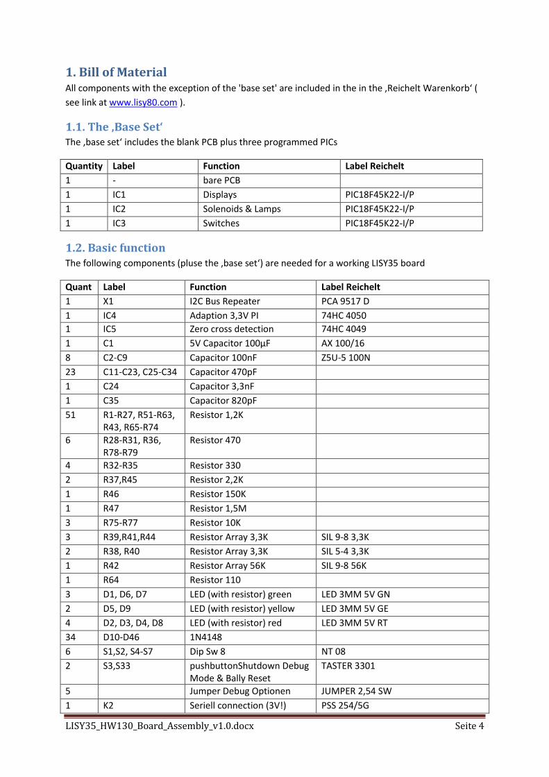
1. Bill of Material All components with the exception of the 'base set' are included in the in the ‚Reichelt Warenkorb‘ (
see link at www.lisy80.com ).
1.1. The ‚Base Set‘ The ‚base set‘ includes the blank PCB plus three programmed PICs
Quantity Label Function Label Reichelt
1 - bare PCB
1 IC1 Displays PIC18F45K22-I/P
1 IC2 Solenoids & Lamps PIC18F45K22-I/P
1 IC3 Switches PIC18F45K22-I/P
1.2. Basic function The following components (pluse the ‚base set‘) are needed for a working LISY35 board
Quant Label Function Label Reichelt
1 X1 I2C Bus Repeater PCA 9517 D
1 IC4 Adaption 3,3V PI 74HC 4050
1 IC5 Zero cross detection 74HC 4049
1 C1 5V Capacitor 100µF AX 100/16
8 C2-C9 Capacitor 100nF Z5U-5 100N
23 C11-C23, C25-C34 Capacitor 470pF
1 C24 Capacitor 3,3nF
1 C35 Capacitor 820pF
51 R1-R27, R51-R63, R43, R65-R74
Resistor 1,2K
6 R28-R31, R36, R78-R79
Resistor 470
4 R32-R35 Resistor 330
2 R37,R45 Resistor 2,2K
1 R46 Resistor 150K
1 R47 Resistor 1,5M
3 R75-R77 Resistor 10K
3 R39,R41,R44 Resistor Array 3,3K SIL 9-8 3,3K
2 R38, R40 Resistor Array 3,3K SIL 5-4 3,3K
1 R42 Resistor Array 56K SIL 9-8 56K
1 R64 Resistor 110
3 D1, D6, D7 LED (with resistor) green LED 3MM 5V GN
2 D5, D9 LED (with resistor) yellow LED 3MM 5V GE
4 D2, D3, D4, D8 LED (with resistor) red LED 3MM 5V RT
34 D10-D46 1N4148
6 S1,S2, S4-S7 Dip Sw 8 NT 08
2 S3,S33 pushbuttonShutdown Debug Mode & Bally Reset
TASTER 3301
5 Jumper Debug Optionen JUMPER 2,54 SW
1 K2 Seriell connection (3V!) PSS 254/5G
LISY35_HW130_Board_Assembly_v1.0.docx Seite 5
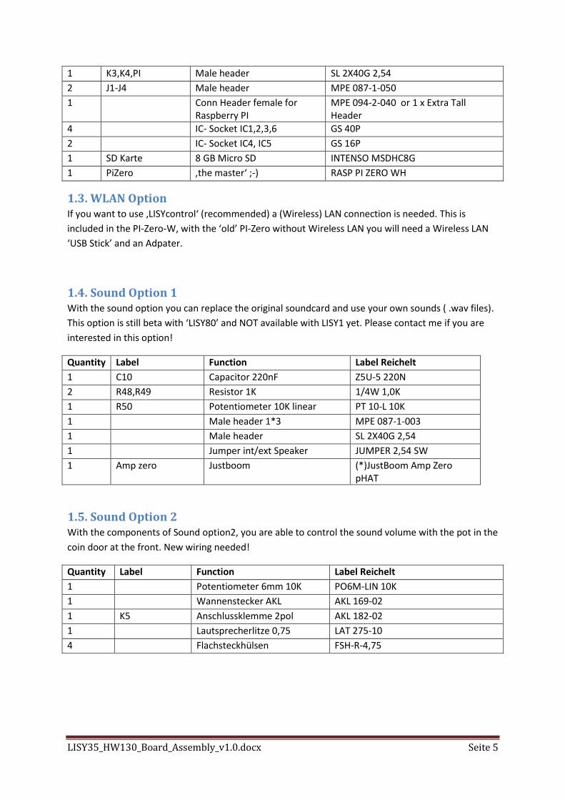
1 K3,K4,PI Male header SL 2X40G 2,54
2 J1-J4 Male header MPE 087-1-050
1 Conn Header female for Raspberry PI
MPE 094-2-040 or 1 x Extra Tall Header
4 IC- Socket IC1,2,3,6 GS 40P
2 IC- Socket IC4, IC5 GS 16P
1 SD Karte 8 GB Micro SD INTENSO MSDHC8G
1 PiZero ‚the master‘ ;-) RASP PI ZERO WH
1.3. WLAN Option If you want to use ‚LISYcontrol‘ (recommended) a (Wireless) LAN connection is needed. This is
included in the PI-Zero-W, with the ‘old’ PI-Zero without Wireless LAN you will need a Wireless LAN
‘USB Stick’ and an Adpater.
1.4. Sound Option 1 With the sound option you can replace the original soundcard and use your own sounds ( .wav files).
This option is still beta with ‘LISY80’ and NOT available with LISY1 yet. Please contact me if you are
interested in this option!
Quantity Label Function Label Reichelt
1 C10 Capacitor 220nF Z5U-5 220N
2 R48,R49 Resistor 1K 1/4W 1,0K
1 R50 Potentiometer 10K linear PT 10-L 10K
1 Male header 1*3 MPE 087-1-003
1 Male header SL 2X40G 2,54
1 Jumper int/ext Speaker JUMPER 2,54 SW
1 Amp zero Justboom (*)JustBoom Amp Zero pHAT
1.5. Sound Option 2 With the components of Sound option2, you are able to control the sound volume with the pot in the
coin door at the front. New wiring needed!
Quantity Label Function Label Reichelt
1 Potentiometer 6mm 10K PO6M-LIN 10K
1 Wannenstecker AKL AKL 169-02
1 K5 Anschlussklemme 2pol AKL 182-02
1 Lautsprecherlitze 0,75 LAT 275-10
4 Flachsteckhülsen FSH-R-4,75
LISY35_HW130_Board_Assembly_v1.0.docx Seite 6
2. Step by Step This Guide starts with the components with the least height and went from there step by step.
Please watch carefully the orientation of the components marked at the PCB. As I did some
‘optimization’ with the wiring (yes I did this by hand) you cannot expect that all parts have the same
orientation. Especially with the resistor Arrays take a second look to be on the save side and watch
the right position of ‘PIN1 ‘.
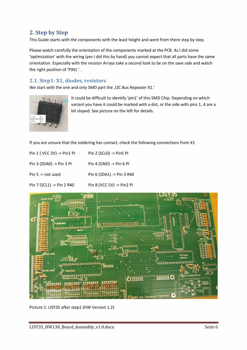
2.1. Step1: X1, diodes, resistors We start with the one and only SMD part the ‚I2C Bus Repeater X1.‘
It could be difficult to identify ‘pin1’ of this SMD Chip. Depending on which
variant you have it could be marked with a dot, or the side with pins 1..4 are a
bit sloped. See picture on the left for details.
If you are unsure that the soldering has contact, check the following connections from X1
Pin 1 ( VCC 3V) -> Pin1 PI Pin 2 (SCL0) -> Pin5 PI
Pin 3 (SDA0) -> Pin 3 PI Pin 4 (GND) -> Pin 6 PI
Pin 5 -> not used Pin 6 (SDA1) -> Pin 3 R40
Pin 7 (SCL1) -> Pin 2 R40 Pin 8 (VCC 5V) -> Pin2 PI
Picture 1: LISY35 after step1 (HW Version 1.2)
LISY35_HW130_Board_Assembly_v1.0.docx Seite 7
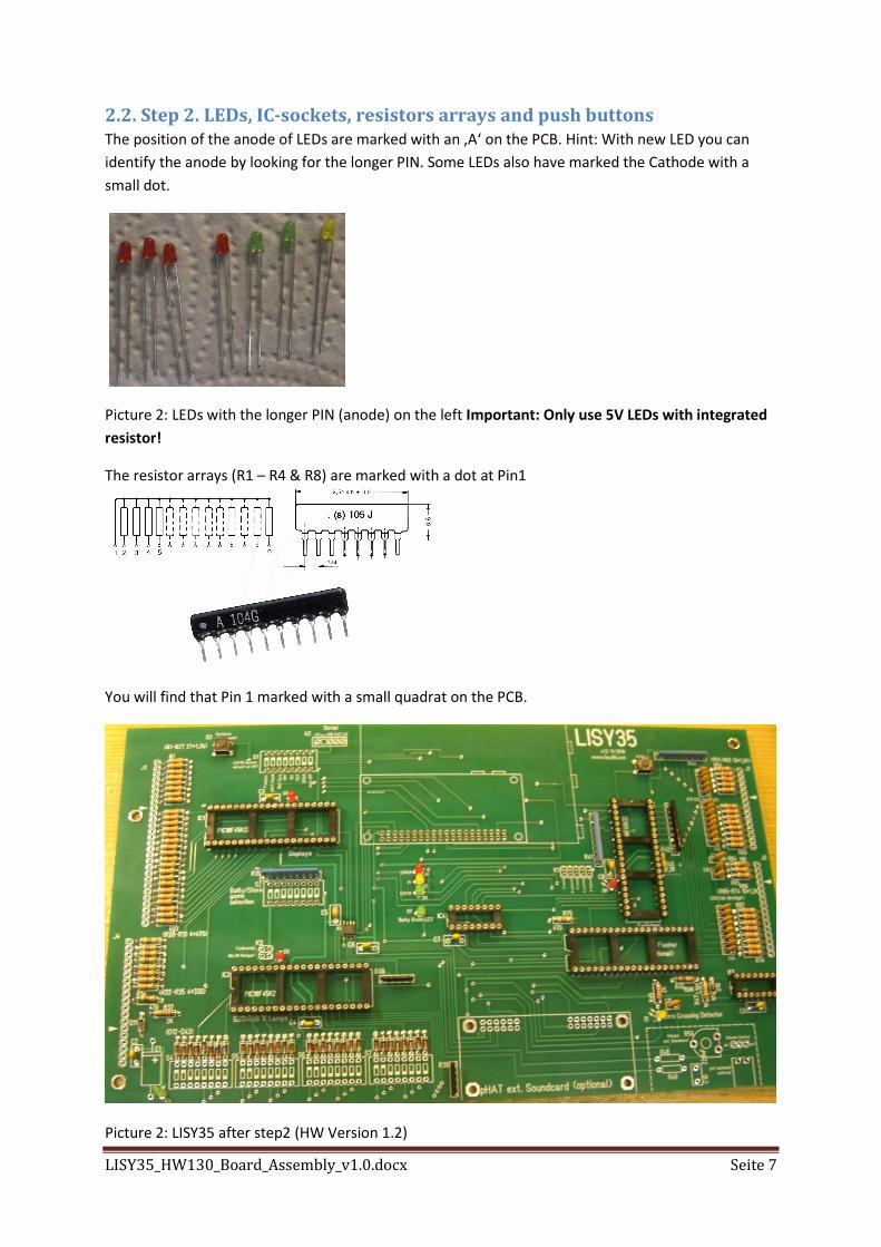
2.2. Step 2. LEDs, IC-sockets, resistors arrays and push buttons The position of the anode of LEDs are marked with an ‚A‘ on the PCB. Hint: With new LED you can
identify the anode by looking for the longer PIN. Some LEDs also have marked the Cathode with a
small dot.
Picture 2: LEDs with the longer PIN (anode) on the left Important: Only use 5V LEDs with integrated
resistor!
The resistor arrays (R1 – R4 & R8) are marked with a dot at Pin1
You will find that Pin 1 marked with a small quadrat on the PCB.
Picture 2: LISY35 after step2 (HW Version 1.2)
LISY35_HW130_Board_Assembly_v1.0.docx Seite 8
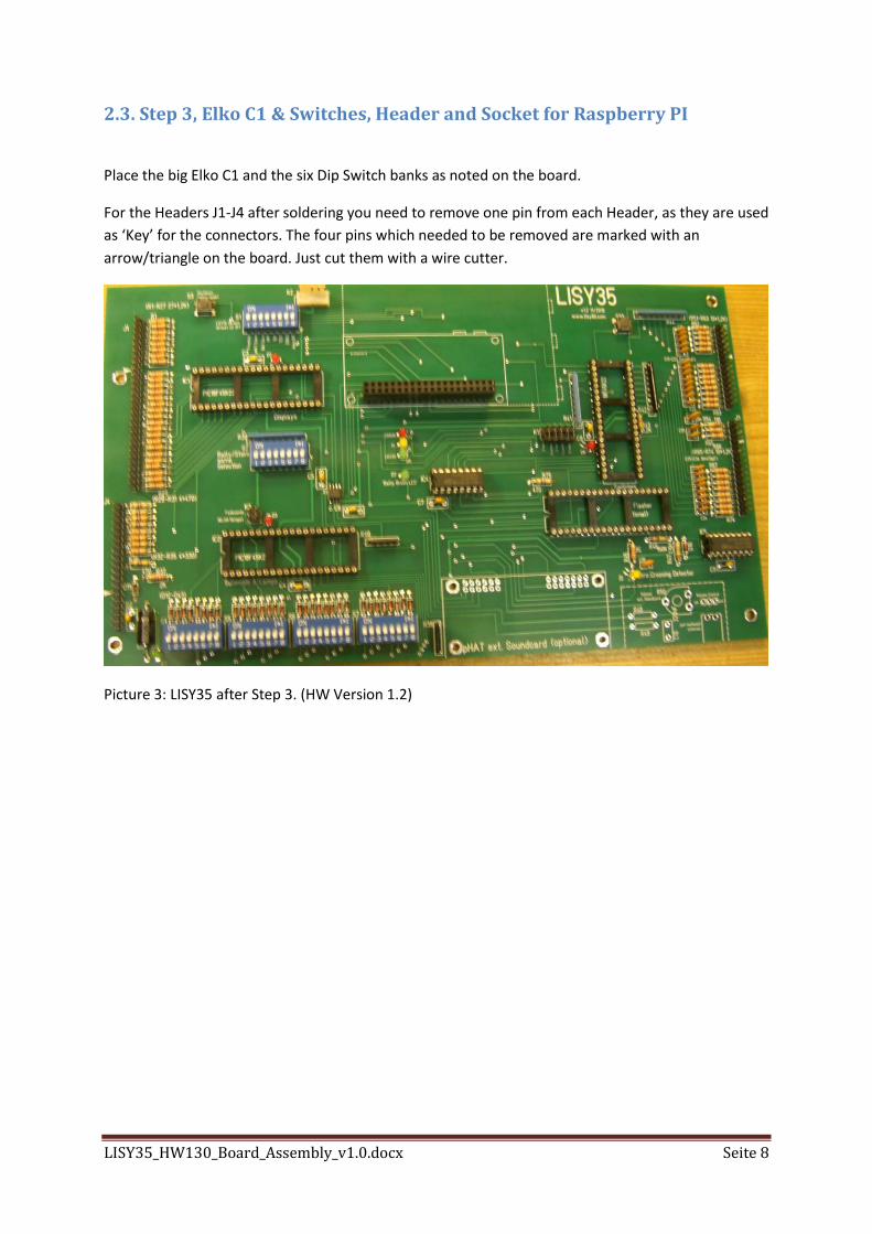
2.3. Step 3, Elko C1 & Switches, Header and Socket for Raspberry PI
Place the big Elko C1 and the six Dip Switch banks as noted on the board.
For the Headers J1-J4 after soldering you need to remove one pin from each Header, as they are used
as ‘Key’ for the connectors. The four pins which needed to be removed are marked with an
arrow/triangle on the board. Just cut them with a wire cutter.
Picture 3: LISY35 after Step 3. (HW Version 1.2)
LISY35_HW130_Board_Assembly_v1.0.docx Seite 9
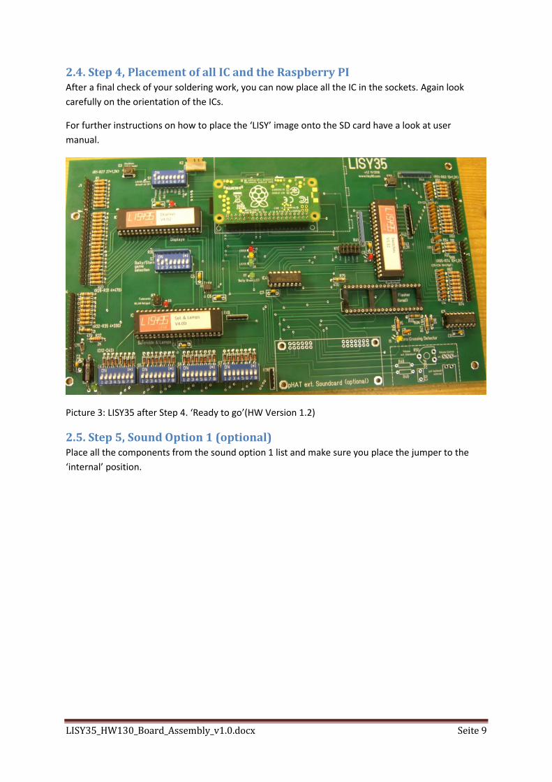
2.4. Step 4, Placement of all IC and the Raspberry PI After a final check of your soldering work, you can now place all the IC in the sockets. Again look
carefully on the orientation of the ICs.
For further instructions on how to place the ‘LISY’ image onto the SD card have a look at user
manual.
Picture 3: LISY35 after Step 4. ‘Ready to go’(HW Version 1.2)
2.5. Step 5, Sound Option 1 (optional) Place all the components from the sound option 1 list and make sure you place the jumper to the
‘internal’ position.