sulfur submerged pumps, molten sulfur pumps, chemical centrifugal pump

2 0 0 9 ED I TI O N
PRODUCT CATALOG& Engineering Reference
L I Q U I F L O C H E M I C A L P R O C E S S I N G P U M P S
Sulfuric Acid, 1 0 -7 5 % • Amyl Acetate • Tallow •
Hydrogen Peroxide, 5 0 % • G lucose (Corn Syrup) •
G lycerin • Hydrochloric Acid, 3 7 % • Methanol •
Sodium Hydroxide, 5 0 % • Aluminum Sulfate •
N itric Acid, 2 0 % • O leic Acid • Benzene • Sul
Cyclohexane • Xylene • Pentane • W ater, deion•
Ammonium Sulfate • Pyridine • Sulfur, molten • Jet
Jet Fuel • Acetonitrile • Maleic Acid • Urea • Dioc
Tetrahydrofuran (THF) • Ferric Sulfate • Hydrazine •
Ethanol • Sodium Hypochlorite, 2 0 % • Chlorofor
Potassium N itrate • Vinyl Chloride • Benzoic Acid
G asoline • Toluene • Silver N itrate • N aphthalene
Acetic Acid • Propylene G lycol • Kerosene •
Sulfuric Acid, 9 3 -1 0 0 % • Butyl Acetate • Ether
Lactic Acid • Tall O il (Liquid Rosin) • Phenol • Fatty
Butane • Hydrobromic Acid, 2 0 % • O leum •
Trichloroethane • Bitumen • Calcium Hydroxide •
Methylene Chloride • Brine (N aCl & W ater) •
Cyclohexanol • Fluorosilicic Acid • Potassium
Dowtherm • O xalic Acid • Thionyl Chloride •
Aniline • Potassium Permanganate • Citric Acid •
Paraffin • Mineral O il • Toluenesulfonic Acid •
Asphalt • Potassium Hydroxide, 5 0 % • Calcium
Brominhlorite • Formaldehyde • Sulfuric Acid,
Copper Sulfate • Sodium Peroxide • Barium Barium
Hydrogen Peropyl Alcohol • Crude O il • Dioctyl
Ammonium Hydroxide • Hyd Chlorobenzene •
Hydrofluoric Acid, 2 0 % • Ferric Chloride • Pro
Diethylamine (DEA) • Sodium Silicate • Phosphoric
N itrous Acid • Freon, general • N aphtha • To
Isopropyl Alcohol • Carbon Disulfide • Hydrazine
Methyl Ethyl Ketone (MEK) • Chromic Acid, 3 0 %
Acetone • Perchloroethylene • Ethylene G lycol •
Sodium Bicarbonate • Aqua Regia • Sulfurous Acid
Butyl Alcohol • Sodium Sulfide • Ammonium
Pyridine • W ater, distilled • Chlorine, anhydro
Hexane • Sodium Bisulfite • Diethylether • Boric
Perchloric Acid • Carbonic Acid • Acetaldehyde •
Toluene Di-Isocyanate (TDI) • Heptane • Benzyl
Alcohol • Hydraulic Fluid • Sodium Chlorate •
Ethylene O xide • Ammonia, anhydrous • Sulfuric
Vinyl Chloride • Potassium N itrate • G lycerin
Carbon Tetrachloride • Diesel Fuel • Butadiene •
Sodium Chloride • Aluminum Potassium Sulfate,
Trichlorotrifluoroethane • Ethanol •Sulfuric Acid
Ammonium N itrate • Hexane • Calcium Chloride •
Methylene p-diphenyl-Di-Isocyanate (MDI) • Ben
Aluminum Chloride, 2 0 % • Ether • Phthalic Acid •
O xalicl • Chlorosulfonic Acid • Ethyl Acetate •
Trichloroethylene • Sulfuric Acid, 1 0 -7 5 % • Amyl
Acetate • Tallow • Hydrogen Peroxide, 5 0 % •
G lucose (Corn Syrup) • G lycerin • Hydrochloric
Xylene • Methanol • Sodium Hydroxide, 5 0 % •
Aluminum Sulfate • N itric Acid, 2 0 % • O leic A
Benzene • Cyclohexane • Butane • Pentane •
W ater, deionized • Ammonium Sulfate • Pyridine •
Sulfur, molten • Jet Fuel • Acetonitrile • Maleic Acid
Urea • Tetrahydrofuran (THF) • Ferric Sulfate •
Hydrazine • Ethanol • Sodium Hypochlorite, 2 0 % •
Chloroform • Potassium N itrate • Vinyl Chloride •
Benzoic Acid • G asoline • Toluene • Silver N itrate
N aphthalene • Acetic Acid • Propylene G lycol •
K • S lfuric Acid, 9 3 -1 0 0 % • Butyl Acetate
TM For Over 35 Years, Liquiflo Pumps Have Handled Thousands
of Difficult Chemica ls
316 SS, Alloy-20 , Alloy-C, Titanium & PFA-Lined SS
Gear & Centrifuga l Pumps316 SS, Alloy-20 , Alloy-C, Titanium & PFA-Lined SS
SEALED & M AGN ETIC DRIV E

I N T R O D U C T I O N 2 0 0 9 E D I T I O N
For ove r 3 5 ye a r s ,
L i q u i f l o p u m p s h a ve h a n d l e d
t h ou sa n d s o f d i f f i c u l t c h e m i c a l s
Liquiflo specializes in the design and manufacture of high-alloy gear pumps and centrifugal pumps for the chemical processing industry. Our extensive experience and wide offering ofcorrosion and wear resistant materials enable us to engineer pumps capable of handling some of the most difficult and challenging chemical applications. These include pumping acids, caustics, corrosive salts, solvents, polymers and other types of chemicals, as well as hot or cold, viscous, extremely thin and hazardous liquids.
Liquiflo offers a large selection of standard Sealed and Mag-drive pumps (see chart below), repair kits, parts, options and accessories, which are available for immediate delivery. In addition,Liquiflo can customize pumps to meet your specific requirements. Our experienced applicationengineers, customer service representatives and worldwide network of distributors are available to assist you with your special chemical pumping applications.
This 153-page, full-color catalog describes Liquiflo’s extensive product offering in a clear and easy-to-understand format. A useful and comprehensive Engineering reference is included in the second part of the catalog. New to the 2009 edition are improved GeneralInformation and Engineering sections, the expanded H-Series – including the new H12 Close-Coupled Pumps, the addition of the new Max® Series High-Pressure Gear Pumps, and thenew Centry® Series Centrifugal Pumps.
L I Q U I F L O C H E M I C A L P R O C E S S I N G P U M P S
443 N orth Avenue
Garw ood
N ew Jersey
07027
USA
tel. 908 .518 .0777
fax . 908 .518 .1847
Liquiflo .com
OVE RVI E W o f L I QU I FLO GE AR & C E N T RI FU GAL P U M P FAM I L I E S
GE AR P U M P S C E N T RI FU GAL
General Purpose Gear Pumps Special Purpose Gear Pumps
* The 3-Series was replaced by the H-Series; the H-Series is recommended for all new applications and 3-Series upgrades.
H-Series 3-Series * 2 -Series 4 -Series M ax ® Series Centry ® Series
Heavy-Duty Industria l Standard-Duty Ultra -Low -Flow Low -Flow High-Presure Sub-AN SI
• 11 sizes • 11 sizes • 2 sizes • 4 sizes • 9 sizes • 3 sizes
• Sealed • Sealed • Mag-Drive • Mag-Drive • Sealed • Sealed
• Mag-Drive • Mag-Drive • Mag-Drive • Mag-Drive
M ax imum Flow Rates (approx .)
• 30 GPM • 55 GPM • 30 GPH • 3.5 GPM • 20 GPM • 150 GPM
M ax imum Differentia l Pressures
• 225 PSI • 100 PSI • 225 PSI • 100 PSI • 350 PSI • 100 ft (head)
Basic M ateria ls of Construction
• 316 SS • 316 SS • 316 SS • 316 SS • 316 SS • 316 SS
• Alloy-C • Alloy-C • Alloy-C • Titanium • Alloy-C
• Alloy-20 • Titanium
P U M P S
1t e l . 9 0 8 . 5 1 8 . 0 7 7 7 f a x . 9 0 8 . 5 1 8 . 1 8 4 7 w w w . l i q u i f l o . c o m
L I Q U I F L O C H E M I C A L P R O C E S S I N G P U M P S
P R O D U C T C AT A L O GTA B L E O F C O N T E N T S
G E N E R A L I N F O R M A T I O N
H-Series General Information 28-29
Model Coding 30-31
Specification Sheets 32-42
2-Series General Information 60
Model Coding 61
Specification Sheet 62
4-Series General Information 63
Model Coding 64
Specification Sheet 65
Max®-Series General Information 66-67
Model Coding 68
Specification Sheets 69-77
Centry ®-Series General Information 78-79
Model Coding 80
Specification Sheets 81-83
© Copyright 2009 Liquiflo. All rights reserved.
2 0 0 9 E d i t i o n
3-Series General Information 44-45
Model Coding 46-47
Specification Sheets 48-58
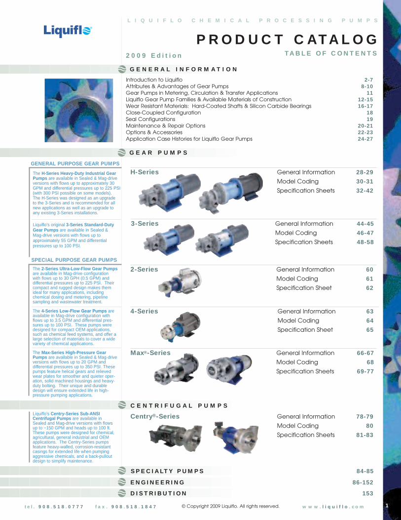
Introduction to Liquiflo 2-7Attributes & Advantages of Gear Pumps 8-10Gear Pumps in Metering, Circulation & Transfer Applications 11Liquiflo Gear Pump Families & Available Materials of Construction 12-15Wear Resistant Materials: Hard-Coated Shafts & Silicon Carbide Bearings 16-17Close-Coupled Configuration 18Seal Configurations 19Maintenance & Repair Options 20-21Options & Accessories 22-23Application Case Histories for Liquiflo Gear Pumps 24-27
G E A R P U M P S
The H-Series Heavy-Duty Industrial GearPumps are available in Sealed & Mag-driveversions with flows up to approximately 30GPM and differential pressures up to 225 PSI(with 300 PSI possible on some models).The H-Series was designed as an upgrade to the 3-Series and is recommended for allnew applications as well as an upgrade toany existing 3-Series installations.
Liquiflo’s original 3-Series Standard-DutyGear Pumps are available in Sealed & Mag-drive versions with flows up toapproximately 55 GPM and differentialpressures up to 100 PSI.
The 2-Series Ultra-Low-Flow Gear Pumpsare available in Mag-drive configuration with flows up to 30 GPH (0.5 GPM) anddifferential pressures up to 225 PSI. Theircompact and rugged design makes themideal for many applications, includingchemical dosing and metering, pipelinesampling and wastewater treatment.
The 4-Series Low-Flow Gear Pumps areavailable in Mag-drive configuration withflows up to 3.5 GPM and differential pres-sures up to 100 PSI. These pumps weredesigned for compact OEM applications,such as chemical feed systems, and offer alarge selection of materials to cover a widevariety of chemical applications.
The Max-Series High-Pressure GearPumps are available in Sealed & Mag-driveversions with flows up to 20 GPM anddifferential pressures up to 350 PSI. Thesepumps feature helical gears and relievedwear plates for smoother and quieter oper-ation, solid machined housings and heavy-duty bolting. Their unique and durabledesign will ensure extended life in high-pressure pumping applications.
GENERAL PURPOSE GEAR PUMPS
SPECIAL PURPOSE GEAR PUMPS
C E N T R I F U G A L P U M P SLiquiflo's Centry-Series Sub-ANSICentrifugal Pumps are available in Sealed and Mag-drive versions with flows up to ~150 GPM and heads up to 100 ft. These pumps were designed for chemical,agricultural, general industrial and OEMapplications. The Centry-Series pumpsfeature heavy-walled, corrosion-resistantcasings for extended life when pumpingaggressive chemicals, and a back-pulloutdesign to simplify maintenance.
D I S T R I B U T I O N 153
S P E C I A LT Y P U M P S 84-85
E N G I N E E R I N G 86-152
W HO IS LIQUIFLO?
Liquiflo is a division of Picut Industries with headquarters located in Garwood, NJ, USA. Picut Industries is a privatelyowned conglomerate of companies that produces precision products for the chemical, aerospace, automotive,electronics and commercial manufacturing industries. Picut Industries has over 350 employees and approximately280,000 square feet of modern manufacturing facilities. (For more information on Picut Industries, please refer to thefollowing website: www.picutindustries.com)
Since 1972, Liquiflo has manufactured high-alloy gear pumps and centrifugal pumps – designed specifically to meetthe demanding requirements of the chemical processing industry. Liquiflo gear pumps have handled thousands ofdifficult chemicals and have been successfully applied in many difficult pumping situations, including low-viscosity,high-viscosity, low-temperature and high-temperature applications.
One of Liquiflo’s strengths is the application of gear pumps to low-viscosity fluids by using a wide variety of non-metallic, self-lubricating components. In addition, Liquiflo was one of the first companies to apply magnetic-drivetechnology to gear pumps. By focusing mainly on chemical applications, Liquiflo has earned the reputation as oneof the world’s leading pump companies.
I N T ROD U C T I ON T O L I QU I FLO
WHY CHOOSE LIQUIFLO?
THE LIQUIFLO ADVANTAGE
n For decades, Liquiflo has led the field in engineered pumps designed to meet customer needs for metering, circulation and transfer of process fluids. Our pumps provide high reliability for handling difficult services, including high-temperature, high-pressure and low-flow chemical applications. The benefits to the customer include increased uptime, high operational effectiveness and less frequent service requirements.
n Liquiflo has over 35 years experience pumping thousands of difficult chemicals including acids, caustics, corrosive salts, solvents, polymers and other types of chemicals, as well as hot or cold, viscous, extremely thin and hazardous liquids. To date, Liquiflo has sold well over 100,000 pumps for thousands of different applications around the globe.
n Liquiflo offers a wide selection of standard high-alloy gear and centrifugal pumps to handle a variety of chemical applications. In addition, Liquiflo can custom engineer pumps to meet your specific requirements.
n Most Liquiflo pumps models have the choice of any sealing, mounting and port configurations: Sealed vs.Mag-drive; long-coupled vs. close-coupled; threaded vs. flanged ports.
n Liquiflo offers a large selection of ancillary options and accessories. These include repair kits, pump cartridges, ANSI & DIN flanges, sanitary fittings, temperature-control jackets, relief valves, electric or air motors, variable speed drives, gearboxes, base plate mounting, and more.
n Liquiflo’s conscientious and efficient operation ensures that quality products will reach our customers in the fastest time possible. Standard products and parts can usually be shipped in 1 to 3 workdays.
n Liquiflo’s comprehensive, full-color product literature is available in hardcopy form upon request, and is also available electronically on our website: www.liquiflo.com. Our website supports all standard Liquiflo pump models, including the Endura family of magnetically-driven centrifugal pumps.
n Liquiflo offers the following special options: custom assemblies, certified or custom drawings, Certificate of Conformance, Foundry Certified Material Test Reports, witnessed performance and hydrostatic testing, and custom tagging.
n Liquiflo’s experienced application engineers, customer service representatives and worldwide network of distributors are always available to assist you with your special chemical pumping applications.
2

3t e l . 9 0 8 . 5 1 8 . 0 7 7 7 f a x . 9 0 8 . 5 1 8 . 1 8 4 7 w w w . l i q u i f l o . c o m
MARKETS SERVED
Adhesives & Coatings Low-flow dispensing (glue for folding boxboards, parts assembly using glue instead of fasteners), spray coating with nozzles, difficult to handle ingredients(fast drying acrylic emulsions, isocyanates, solvents, plasticizers)
Chemical Plants Loading & unloading, process production areas, utilities (water, wastewater andboiler feedwater treatment), pilot plants, polymer manufacturing, monomers, DIwater, defoamers, catalysts, dyes, odor control additives, specialty chemicals
Fertilizers Nitric acid, sulfuric acid, phosphoric acid, ammonia, production of urea-ammonium nitrate (UAN)
Food & Dairy Canneries, dairies, meat processing, snack foods, raw material handling (salt andbrine solutions, vinegar, sugar solutions, additives), utilities (water, wastewater andboiler feedwater treatment; clean-in-place systems dispensing cleansing chemicals)
Iron & Steel Mills Utilities (water, wastewater and boiler feedwater treatment), acids for pickling, acidsand caustic solutions for finishing
Metal Finishing Surface cleaning (alkaline and caustic to degrease, rinse aids, neutralizingchemicals), zinc coatings (acids for pickling, zinc phosphate), electroplating (nickelor copper solutions), anodizing, passivation (bath in nitric or citric acid solutions)
Mining & Minerals Extraction (acids, solvents), reaction to cause precipitation (caustics), coagulationfor solids-liquid separation (polymers)
Municipalities Production of drinking water (flocculants, alum, sodium hypochlorite for disinfection),wastewater treatment (polymer for coagulating suspended solids, sludgeconditioning, sodium hypochlorite for disinfection of discharged treated water)
Personal & Household Products
Soap, laundry detergent, fabric conditioner, dishwasher detergent, householdcleaners, dyes, fragrances, surfactants
Pesticides Dilution into final product, incorporation of pesticide solution into dry product
Pharmaceuticals Bulk chemical handling (hydrochloric acid, solvents), utilities (cooling tower watertreatment, boiler feedwater treatment, wastewater chemical treatment, pumpinghigh purity water)
Power Plants & Utilities Boiler feedwater treatment chemicals, makeup water system regeneration,biocides for cooling tower water
Printing Inks for printing press manufacturers, publishers with printing operations and OEM’sthat build printing presses
Pulp & Paper Retention & drainage aids, biocides, wet strength additives, dry strength additives,coating polymers, sizing, pigments & fillers, bleaching chemicals
Refineries Utilities (water, wastewater and boiler feedwater treatment), solvent extractionprocesses (phenol or furfural to remove aromatics), chemical treatment (causticsolutions for removing sulfuric acid), fuel additives (ethanol and ethers)
Textiles Bleaching chemicals (hydrogen peroxide), caustics, fabric conditioners, dyes, utilities (water, wastewater and boiler feedwater treatment)
W hat a re some of the typica l markets and applica tio ns served by Liquiflo?
Some Applications
L I Q U I F L O C H E M I C A L P R O C E S S I N G P U M P S
I N T ROD U C T I ON T O L I QU I FLO
OEMs (Original Equipment Manufacturers)
Chemical metering systems, chillers, air-conditioning & refrigeration units, constanttemperature baths, printing presses, liquid dispensers (soaps, glues, paints, etc.)

I N T ROD U C T I ON T O L I QU I FLO
Headquartered in Garwood, NJ, Liquiflo’sresources include a highly skilled workforceand spacious manufacturing facilitiesequipped with high-tech machinery andinstrumentation. Liquiflo is also supported byour network of technically astute domesticand international distributors.
Loca tion & Resources
4
Liquiflo’s conscientious and efficient approach to manufacturing ensures that quality products will reachour customers in the fastest time possible. Our large inventory of parts and products enables us to shipover 90% of what we offer in just 1 to 3 workdays.
The “Flo ” of Liquiflo
Receiving
Product Assembly
Inspection
Stock room
Shipping
Product Testing
Packaging
Documenta tionTest Reports, Tagging,
Certificates, Product Manuals,Bill of Materials, etc.
Repa ir Kits,Accessories or
Spar e Parts
Specia l ProcessesParts Machining & Polishing,
Parts Trimming, MagnetAssembly & Balancing,
Containment Can Assembly& Testing, etc.
Product toCustomer
PurchasingParts & Materials
“ The Liqui -Flo Char t ”
Customer ServiceOrder Receiving &Acknowledgement
L I Q U I F L O C H E M I C A L P R O C E S S I N G P U M P S
5
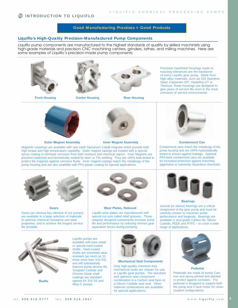
Liquiflo pump components are manufactured to the highest standards of quality by skilled machinists usinghigh-grade materials and precision CNC machining centers, grinders, lathes, and milling machines. Here aresome examples of Liquiflo’s precision-made pump components:
Liquiflo’s High-Qua lity Precision-M anufactured Pump Components
Good M anufacturing Practices = Good Products
I N T ROD U C T I ON T O L I QU I FLO
t e l . 9 0 8 . 5 1 8 . 0 7 7 7 f a x . 9 0 8 . 5 1 8 . 1 8 4 7 w w w . l i q u i f l o . c o m
Precision-machined housings made toexacting tolerances are the backbone of every Liquiflo gear pump. Made fromhigh-alloy materials, such as 316 StainlessSteel, Carpenter-20®, Hastelloy-C® orTitanium, these housings are designed togive years of service life even in the mostcorrosive of service environments.
Front Housing Center Housing Rear Housing
Outer Magnet Assembly Inner Magnet Assembly
Magnetic couplings are available with rare earth Samarium Cobalt magnets which provide both high torque and high temperature capability. Outer magnet casings are treated with a special epoxy coating to minimize corrosion from both moisture and chemical vapors. Inner Magnets areprecision balanced and hermetically sealed by laser or TIG welding. They are 100% leak-tested toprotect the magnets against corrosive fluids. Inner magnet casings match the metallurgy of thepump housing and are also available with PFA plastic coating for special applications.
Containment Can
Containment cans match the metallurgy of thepump housing and are 100% hydrostaticallytested to ensure against leakage. Optional PFA-lined containment cans are available for increased protection against extremelyaggressive or extremely hazardous chemicals.
Gears Wear Plates, Relieved
Gears (an obvious key element of our pumps)are available in a large selection of materials to optimize chemical resistance and wearproperties, and to achieve the longest servicelife possible.
Shafts
Bearings
Liquiflo pumps areavailable with bare metalor special hard-coatedshafts. Hard-coatedshafts are extremely wearresistant (as much as 10times more than 316 SS)and will substantiallyimprove pump service life.Tungsten Carbide andChrome Oxide shaftcoatings are standardoptions for 316 SS andAlloy-C pumps.
Liquiflo wear plates are manufactured withspecial cut-outs called relief grooves. Theseuniquely designed components increase pumplife and performance by reducing intrinsic gearseparation forces during pumping.
Journal (or sleeve) bearings are a criticalcomponent of the gear pump and must becarefully chosen to maximize pumpperformance and longevity. Bearings areavailable in acid-grade Carbon 60, SiliconCarbide, PEEK and PTFE – to cover a widerange of applications.
Only high-quality chemical dutymechanical seals are chosen for usein Liquiflo gear pumps. The standardand optimum seal componentcombination is a Carbon seal face vs.a Silicon Carbide seal seat. Othermaterial combinations are availablefor special applications.
Pedestals are made of sturdy CastIron and epoxy-primed and paintedto protect against corrosion. Thepedestal is designed to support boththe pump and C-face motor for close-coupled configurations.
Mechanical Seal Components
Pedestal

6
I N T ROD U C T I ON T O L I QU I FLO
All Liquiflo parts – whether produced internally or from an externalsource – are carefully inspected for compliance with specificationsbefore they are stocked, shipped or used to produce a final product.Over 70% of Liquiflo parts are produced internally.
Parts Inspection & Ba lancing
Liquiflo pumps and products are assembledby trained technicians using documentedstandard operating procedures.
Product Assembly
Technicians measuring the dimensions of pump components with precisioncalipers: Liquiflo pump components are precisely manufactured to tolerancesas low as .0004 inches (10 microns).
Technician balancing inner magnet for a mag-drivepump: Precision balancing of internal componentssignificantly extends the service life of our products.
Technicians assembling a group of chiller circulation pumps for a large OEM: Whether it’s a single pump order or a large pump order, Liquiflo is committed tocompleting each order accurately and on schedule.
Technician assembling an outer magnet for a mag-drive pump: Liquiflo produces a variety of magnetic couplings to fit each pump model and match the torque transmission required by the application.

L I Q U I F L O C H E M I C A L P R O C E S S I N G P U M P S
7
All functional products – includingpumps, replacement cartridges andrelief valves – are performance-tested before shipping. Testing isperformed in accordance withHydraulic Institute standards.
Product Testing
I N T ROD U C T I ON T O L I QU I FLO
Quick deliveries is one of Liquiflo’s major advantages. Liquiflo makes this possible by keeping a multi-million dollarinventory of over 100,000 individual parts comprised of over 3,000 unique part numbers. Over 90% of these partscan be shipped next-day. Standard pumpsand products are typically shipped within 3 workdays.
Stock room & Shipping
Large order of gear pumpsclose-coupled to electric
motors going to OEMfactory: Liquiflo pumps are
available with a largeselection of ancillary
options and accessories.These include flanged
ports, relief valves,temperature control
jackets, variable speeddrives, gear reducers, air
motors, base platemounting and more.
Technician testing performance of a gear pump: Testing is conducted withwater at room temperature. Each pumpmodel must meet its specification for flowrate at various differential pressures.
t e l . 9 0 8 . 5 1 8 . 0 7 7 7 f a x . 9 0 8 . 5 1 8 . 1 8 4 7 w w w . l i q u i f l o . c o m
8 t e l . 9 0 8 . 5 1 8 . 0 7 7 7 f a x . 9 0 8 . 5 1 8 . 1 8 4 7 w w w . l i q u i f l o . c o m
Gear Pumps are positive displacement pumps that are frequently used for metering, circulating and transferring both thin and viscous fluids at differential pressures higher than are typically achievable with centrifugal pumps.
Gear pumps can be considered a preferable alternative to Diaphragmpumps because they do not pulse or require an expensive air source to operate. For metering applications, Gear pumps, unlike Diaphragm pumps,do not require pulsation dampeners or other ancillary equipment. In continuous duty applications, Gear pumps generally last longer than Diaphragm, Progressive Cavity or Peristaltic pumps, which require frequent part replacements, such as diaphragms, stators, rotors or hoses.
The excellent characteristics of gear pumps (wide range of flow and pressure, pulseless flow, small andcompact design, long service life, ease of repair, etc.) have always made them a preferred choice ofpumping methods. Originally, gear pumps were mainly used in applications for pumping higher viscosity fluids, such as oils, which have good lubricating properties for the internal components of the pump. However, Liquiflo extended the useful range of gear pumps down to the extremely low viscosity of 0.3 cP for the chemical industry. This achievement was accomplished by using gears made from self-lubricatingengineered plastics, such as Teflon and PEEK, and developing special hardened Stainless Steel and Hastelloy-Cshafts that further extend the service life of gear pumps even when used with viscosities as low as 0.3 cP.
W hy Use Gear Pumps?
AT T RI BU T E S & AD VAN TAGE S OF GE AR P U M P S
Attributes & Advantages of Gear Pumps:
• Ideal for low-flow and high-pressure applications
• Virtually no pulsations – ideal for metering applications
• Flow accuracies of 0.5-2.0% are achievable
• Require less auxiliary equipment than Diaphragm pumps (pulsation dampeners, air compressors, dryers, etc.)
• No check valves to clog
• No diaphragms or hoses to rupture and leak
• Reliable – high MTBM (mean time between maintenance)
• Simple to understand and maintain – Repair kits are available which contain all components to completely and easily rebuild all Liquiflo gear pumps to like-new condition
• Self-priming/suction lift capability
• Low NPSHR – smaller pipe diameters are required
• Useful over wide range of viscosities (0.3 to 100,000+ cP)
• Bi-directional flow – interchangeable suction & discharge ports
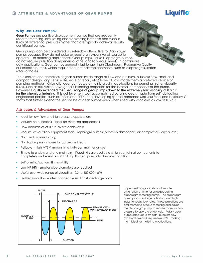
Upper (yellow) graph shows flow rate as function of time for a reciprocatingdiaphragm metering pump. The diaphragmpump produces large pulsations and highinstantaneous flow rates. These pulsations aredetrimental to precise metering and cause the diaphragm pump to require more suctionpressure to operate effectively. Rotary gearpumps produce a smooth, pulseless flow(dashed line) and require less NPSH, makingthem ideal for metering applications.TIME
DISCHARGE
ONE COMPLETE CYCLE
SUCTION
AVERAGEFLOW
PEAK FLOW =x AVERAGE FLOW
FLOW

9
Magnetically-Coupled Pumps have no dynamic seals to leakor replace. Mag-drive pumps provide a simple and securesolution to sealing toxic, noxious, crystallizing or most otherhazardous fluids.
Magnetically-coupled versions are available for all of Liquiflo’s product lines, including the Centry® Series centrifugal pumps.
W hy Use M ag-drive (Sea lless) Gear Pumps?
Mag-Drive Pumps:
• provide the simplest and best method for containing hazardous liquids
• are ideal for applications where absolutely no leakage can be tolerated
• are typically less expensive than double-sealed arrangements
• eliminate cooling loops required on double-sealed arrangements
• eliminate the need to dispose of barrier fluids used on double-sealed pumps
• require less maintenance than mechanically-sealed pumps since there are no seals to replace
Mag-drive pumps transfer power from the motor shaft to the pump drive shaftvia a magnetic coupling. The magneticcoupling consists of an outer magnet andinner magnet, matched in strength. Theouter magnet attached to the motor shaftcauses the inner magnet attached to thepump drive shaft to turn synchronously with the motor. Since the drive shaft iscompletely inside the pump housing, thereis no need for a dynamic seal and thepumped liquid is completely contained.
N o Dynamic Sea lsto Leak or Replace
M AG-DRIVEPUM PS
N o Sea l SupportSystem Requir ed
N o Barrier Fluidsto Dispose of
Simplest M ethod
Eco-Friendly
100% Conta inment
Hazardous Liquids
SAFETY FIRST!
ContainmentCan
OuterMagnet
InnerMagnet
PUMP
MOTOR
Pump Drive Shaft
AT T RI BU T E S & AD VAN TAGE S OF GE AR P U M P S
Motor Shaft
t e l . 9 0 8 . 5 1 8 . 0 7 7 7 f a x . 9 0 8 . 5 1 8 . 1 8 4 7 w w w . l i q u i f l o . c o m

10 t e l . 9 0 8 . 5 1 8 . 0 7 7 7 f a x . 9 0 8 . 5 1 8 . 1 8 4 7 w w w . l i q u i f l o . c o m
Liquiflo specializes in pumping lowviscosity liquids using gear pumps.Since low viscosity fluids have little tono lubricity, Liquiflo uses gears madefrom carefully chosen engineeredplastics such as PEEK or Teflon thathave substantial self-lubricatingproperties as well as excellent wearand corrosion resistant properties. Inaddition, we use hard-coated shaftsthat exhibit extreme resistance towear in the journal-bearing areaseven when pumping extremely thinfluids. Liquiflo has pumped liquids with viscosities as low as 0.3 cP with impressive results. We havedocumented applications of pumpsrunning in excess of 24,000 hourson 0.6 cP liquids.
High-Viscosity Fluids
AT T RI BU T E S & AD VAN TAGE S OF GE AR P U M P S
W hy Use Liquiflo Gear Pumps?Liquiflo has been producing high qua lity gear pumps for the chemica l industry for more than35 years. W ith an ex tensive selection of corrosion -resistant and w ear-resistant materia ls, sea lingconfigura tions and ancilla ry options, Liquiflo Gear Pumps can be custom engineered to handle aw ide range of chemica l pumping applica tions.
Water treatment polymers andfood materials up to 80,000 cP aretypical of the high-viscosity serviceof the H-Series gear pumps. Whenpumping high-viscosity materials, itis normally preferred to use largersize pumps running at slower speedto allow these thicker materials toenter the pump and fully fill thegear teeth cavities. Since slip is nota concern with high-viscosity fluids,gear outer diameters are usuallytrimmed to increase pumpefficiencies. Running largerpumps at lower speeds have the additional benefit of extendingpump life, decreasing pipe frictionlosses and reducing fluid shear.
Low -Viscosity Fluids
Liquiflo gear pumps are used in metering systems where themotor RPM is controlled to regulatepump output. Flow rate, pH levelsor RPM can trigger the control offeedback signals. Liquiflo H-Seriesgear pumps are available in awide variety of flow ranges (11 sizes offered), simplifyingselection for metering applications.(See following page and theEngineering section, page 101, for more information on Metering.)
M etering
Solid or highly viscous chemicalsat room temperature can beeffectively pumped once they are heated to a more fluid state.Liquiflo offers several materialsand ancillary options for thispurpose. Liquiflo’s pump selectionprocess evaluates the effect oftemperature on any nonmetalliccomponents inside the pump. If necessary, these parts will betrimmed to ensure effective and efficient operation at thepumping temperature. Theancillary options include theLiquiflo Temperature ControlJacket, Dual Kan® and PowerFrame. (See pages 22-23.)
High-Tempera ture FluidsAntifreeze, refrigerants or liquefied gases are typicallypumped at temperatures below20°C (i.e., room temperature).Liquiflo has successfully pumpedcold or cryogenic liquids with mag-drive pumps using special-purposematerials and equipment. TheLiquiflo Temperature Control Jacketand Dual Kan® are available forapplications where low liquidtemperatures must be preciselycontrolled. (See page 22.)
Low -Tempera ture Fluids
Crystallizing fluids can be problematicfor pumps with single mechanicalseals. Fluids that crystallize whenexposed to air can cause a crystalbuild-up around the edges of the seal faces, causing damage andpremature seal failure. For this service,Liquiflo offers pumps with doublemechanical seals or sealless magneticdrives. In both cases, the pumpedfluid is isolated from the air, preventingcrystallization. The double seal uses a pressurized barrier fluid system tocontain the pumpage and flush the seal faces.
Crysta llizing Fluids
Toxic, noxious, flammable,corrosive or other dangerousliquids are best handled usingsealless mag-drive pumps. Thesepumps have no dynamic sealsand therefore completely containthe pumpage. Liquiflo was one ofthe first companies to applymagnetic-drive technology togear pumps. Because of theirsimplicity, and importance tosafety and the environment, allLiquiflo pump models areavailable in mag-driveconfiguration.
Hazardous Fluids

11
GEAR PUM PS IN M ETERING, CIRCULATION & TRANSFER APPLICATIONS
Gear pumps are often used in feedback-controlled metering systems because of their inherent pulseless flowas well as other inherent advantages. Feedback signals from flow meters, pH sensors, tachometers, levelswitches, etc., can control the motor speed and regulate the pump output. For example, an instantaneousflow meter signal can keep the flow rate constant despite changes in pressure, viscosity or temperature; thesignal from a pH meter can vary the flow rate to control a process; or a totalizing flow meter signal can beused to send a specified volume of liquid to a process or tank and then automatically stop the motor.
M etering
Gear pumps are commonly used in applications where liquid needs to be circulated at a uniformrate to control temperature. Examples include cooling systems, such as chillers, air-conditioners andrefrigeration units.
Circula tion
Gear pumps are typically used in applications where liquid needs to be transferred from one locationto another. Examples include loading liquids to vehicles for transportation, unloading liquids to storagetanks, pumping liquid from one tank to another, or filling a tank against gravity.
Transfer
Supply Tank
Gear Pump
Flow M eter
Flow to Process
PIDControl
M otor
Variable Speed Drive
HeatEx changer
HeatSource
M otor
Gear Pump
Variable Speed Drive
CoolantSource
GearPump
StorageTank
M otorVariable
Speed Drive
SupplySource
FeedbackSigna l
t e l . 9 0 8 . 5 1 8 . 0 7 7 7 f a x . 9 0 8 . 5 1 8 . 1 8 4 7 w w w . l i q u i f l o . c o m

12 t e l . 9 0 8 . 5 1 8 . 0 7 7 7 f a x . 9 0 8 . 5 1 8 . 1 8 4 7 w w w . l i q u i f l o . c o m
The H-Series is Liquiflo’s most popula r and versa tile Gear Pump line, and is recommended for a ll new applica tions as w ell as an upgradeto any ex isting 3 -Series insta lla tions.
L I QU I FLO GE AR P U M P FAM I L I E S & AVAI LABLE M AT E RI ALS
GEN ERAL PURPOSE GEAR PUM P FAM ILIES: H-SERIES & 3 -S ERIES
(1) Available in 3-Series only. (Delrin gears are available for repair or replacement only.)
(2) 25% Glass-filled PTFE.
(3) For available seal materials, see page 19.
Note: For additional information on the above materials,
refer to the Engineering section, pages 132-135.
HOUSINGS GEARS WEAR PLATES BEARINGS SHAFTS
316 SS 316 SS Carbon 60 Carbon 60 316 SS
Alloy-C Alloy-C Silicon Carbide Silicon Carbide Alloy-C
Alloy-201 PEEK PEEK PEEK TC-Coated
Ryton Teflon2 Teflon2 CO-Coated
Teflon2
Carbon1
Delrin1
Gear
Shaft
Housing
Bearing
Wear PlateH-SERIES & 3 -SERIES Ava ilable M ateria ls of Constr uction
H-Series: Heavy DutyIndustria l Gear Pump
The H-Series Gear Pumps were designed as anupgrade to Liquiflo’s original 3-Series. With similaroutside dimensions and capacities, the H-Seriesincorporates larger diameter shafts and bearings,allowing them to handle higher pressures withextended service life. The H-Series pumps areavailable in 316 Stainless Steel or Alloy-Cconstruction, and Sealed and Mag-drive versionswith flows up to approximately 30 GPM anddifferential pressures up to 225 PSI with 300 PSIpossible on some models.
Seal 3
3-Series: Standar d Duty Gear Pump
Liquiflo’s original 3-Series Gear Pumps areavailable in Sealed and Mag-Drive versions with flows up to approximately 55 GPMand differential pressures up to 100 PSI.
The majority of low-to-medium flow chemical pumping applications (80-90%) can be handled with Liquiflo’ssignature product lines: the H-Series and 3-Series Gear Pumps. These pumps cover flow rates (Q) up toapproximately 55 GPM and differential pressures (∆P) up to 225 PSI (see graph below).
0 50 100 150 200 250
60
50
30
20
10
0
Q (GPM)
∆P (PSI)
3-Series
H-Series
Performance Range of H-Series & 3 -Series
Gear Pump Families

SPECIAL PURPOSE GEAR PUM P FAM ILIES
M ax ®-Series: High-Pressure Gear Pump
The Max-Series pumps feature helical gears and relievedwear plates for smoother and quieter operation andintrinsic reduction of gear separation forces. Their uniqueand durable design will assure extended life in high-pressure pumping applications. The Max-Series pumps are available in Sealed and Mag-Drive versions with flowsup to 20 GPM and differential pressures up to 350 PSI.The basic material of construction is 316 SS with Titaniumavailable for select models.
Note: See following page for more information on the Max-Series Pumps.
13
L I QU I FLO GE AR P U M P FAM I L I E S & AVAI LABLE M AT E RI ALS
4-Series: Low -Flow Gear Pump
The 4-Series Mag-Drive Gear Pumps were designed for OEMapplications such as chemical feed systems. These pumps offer alarge selection of materials to cover a wide variety of chemicalprocessing applications. A unique feature of the 4-Series pump isits parallel port connections located on the front of the pump.The 4-Series pumps are available in 316 SS, Alloy-C or Titaniumconstruction and deliver flows up to 3.5 GPM at differentialpressures up to 100 PSI.
2-Series: Ultra Low -Flow Gear Pump
The 2-Series Mag-Drive Gear Pumps were designed for low-flowapplications. Their compact and rugged design makes them idealfor many applications, including chemical dosing and metering,pipeline sampling and wastewater treatment. The 2-Series pumpsare available in corrosion-resistant 316 SS construction and deliverflows up to approximately 30 GPH (0.5 GPM) at differential pressures up to 225 PSI.
t e l . 9 0 8 . 5 1 8 . 0 7 7 7 f a x . 9 0 8 . 5 1 8 . 1 8 4 7 w w w . l i q u i f l o . c o m
Note: For more information on the available materials for the pump families listed above, refer to the Engineering section, pages 132-135.
2-Series, 4 -Series & M ax ®-SeriesGear Pumps
For applications involving ultra lowflows, compact chemical meteringsystems or higher differential pressures,Liquiflo offers several special purposegear pump families. (These pumpfamilies are described below.) Theperformance range of the specialpurpose pump families, relative to the H-Series, is shown at right.
Performance Range of Specia lPurpose Gear Pump Families
0 50 100 150 200 250 300 350
20
15
10
5
0
Q (GPM)
∆P (PSI)
Max-Series
2-Series
30
4-Series
H-Series

14
L I QU I FLO GE AR P U M P FAM I L I E S & AVAI LABLE M AT E RI ALS
M ax ®-Series High-Pressure Gear Pump
Close-coupledMag-Drive: Models M0-M8Sealed: Models M5-M8
Close-coupledSealed: Models M0-M4
t e l . 9 0 8 . 5 1 8 . 0 7 7 7 f a x . 9 0 8 . 5 1 8 . 1 8 4 7 w w w . l i q u i f l o . c o m
• Flow s up to 20 GPM
• Pressures up to 350 PSI
• Sea led or M ag-Drive
• 316 SS or Titanium Construction
• Threaded or Flanged Ports
• Ava ilable in 9 sizes
• Close-Coupled
• Tempera ture Control Jackets ava ilable
Heavy-Duty Constr uctionSolid 316 SS or Titanium Body
The M ax -Series heavy duty shaft and bearing design make it lasteven when operating at high differential pressures for extendedlengths of time. Its solid construction and oversized heavy duty boltswill minimize pump distortion caused by piping misalignment. Thepump mounting bracket is made of corrosion resistant 316 SS or sturdy Cast Iron.
Configura tionsM echanica l Sea l or M ag-Drive, Close-Coupled
The M ax -Series pumps are available in either single or doublemechanical seal or mag-drive configurations. The universal seal
housing will accommodate either a single or double mechanical seal.The close-coupled design eliminates difficulties and inconveniences of manually aligning the pump and motor. Max pumps are offered in 316 Stainless Steel or Titanium housings with a variety of internalcomponent materials to optimize your selection for specific chemical applications.
FEATURESThe Liquiflo M ax -Series Gear Pumps will handle differential pressures to 350 PSI and flows to 20 GPM. Their unique, durable design assuresextended life even in high-pressure pumping applications where othergear pumps could fail. The Max-Series pumps feature Helical Gearsand Relieved Wear Plates for smoother and quieter operation.
H ELICAL GEARSThe Liquiflo Max-SeriesGear Pump featuresHelical Gears for bothsmoother and quieteroperation, and longerbearing life due to intrinsic reduction of gear separation forces.
Applica tions for Corrosive Chemica ls
Liquiflo M ax -Series Gear Pumps were designed to handle a variety of chemical processing applicationsincluding the metering and transfer of extremely corrosive and toxic chemicals. The Max is available in severalchoices of corrosion resistant materials including 316 SS and Titanium to optimize longevity and long-termreliability. Liquiflo's highly experienced application engineers can assist you in optimizing the correct choice of materials to suit your specific chemical pumping applications.
17-4 PH SS Integra l Gear-Sha ft ArrangementSealed M ax -Series pumps are available with an integral gear-shaft arrangement made of 17-4 PH SS
(precipitate hardened stainless steel). By using a heat-treated metal-to-metal gear configuration, higherpressures can be achieved without the risk of galling or accelerated wear. 17-4 PH SS materials are onlyrecommended for moderately aggressive chemicals, and metal-to-metal gears should only be applied when pumping liquids with viscosities of at least 100 cP. Contact factory for specific applications.
Note: For more information on the Max-Series Gear
Pumps, see pages 66-77.

Typica l Uses and Applica tions
Liquiflo’s PFA-Lined Gear Pump is an excellent choice for inorganic acids, bases and salts, that are difficultto handle with or require expensive alloys in metallic pumps, such as: Hydrochloric Acid, Ferric Chloride,Sulfuric Acid, Hydrofluoric Acid, Sodium Hypochlorite, Nitric Acid, Sodium Hydroxide and Chromic Acid to name a few. Another key application area is for high purity services where contact with metalliccomponents must be avoided.
L I QU I FLO GE AR P U M P FAM I L I E S & AVAI LABLE M AT E RI ALS
Introducing the PFA-Lined Gear Pump N EW PRODUCT
GEARS
PEEK
Ryton
Teflon
BEARIN GS
Silicon Carbide*
SHAFTS
Silicon Carbide
HOUSIN GS
SS-PFA Lined
M A TERI A LS A V A I LA BLE
W EAR PLATES
Silicon Carbide*
N o Wetted M eta l Components
• PFA-Lined pressure boundary components
• PFA-Encapsulated Inner Magnet
• Self-Sintered Silicon Carbide (SiC) Shafts
• Self-Sintered Silicon Carbide Bearings &Wear Plates
• PEEK, Ryton or Teflon Gears
Advantages of PFA-Lined Sta inless Steel Housings
• Traditional pressure integrity expected of metal pumps
• Exempt from wicking problems associated with fiber reinforced housings
• Limits the effects of heat entrapment andcorresponding thermal expansion issues
• Limits the effects of fluid absorption
• Increases strength and durability required for process pump services
Benefits of SiC Sha fts & Bearings
• Exceptional chemical resistance
• Exceptional wear resistance
PFA-Lined Conta inment Cans
• Alloy-C containment can limits eddy current development and subsequent heat generation
• PFA-lined carbon fiber containment can eliminates eddy currents altogether
Features:• PFA-Lined Sta inless Steel Housings
• SiC Sha fts & Bearings
• PFA-Lined Conta inment Can
• Flow s up to 15 GPM
• Pressures up to 100 PSI
• Tempera tures to 200 ˚F
• Ava ilable in both DIN & AN SI flanged connections
• Currently ava ilable in 7 sizes
15t e l . 9 0 8 . 5 1 8 . 0 7 7 7 f a x . 9 0 8 . 5 1 8 . 1 8 4 7 w w w . l i q u i f l o . c o m
Pump M odel P1 P2 P3 P4 P5 P6 P7
Gear W idth (inches) 0.375 0.625 0.875 1.312 1.000 1.375 1.750
Flow (GPM ) @ 1750 RPM 1.4 2.4 3.4 5.0 8.6 11.8 15.0
Note: For further information about the PFA-Lined Gear Pump, please contact the factory.
* Other materials are available; contact factory. Note: For further information on the above materials, see the Engineering section,
pages 132-135.

Liquiflo uses a selection of three standard materials, 316 SS, Alloy-C and Titanium, for making pumphousings and shafts. These materials are unquestionably the best materials available in the market todayand are obviously chosen for there excellent corrosion resistant properties. Unfortunately, none of theseextremely corrosion resistant materials can be hardened by the conventional means of heat treatmentand therefore only offer limited wear resistant properties. In particular, the areas of the shaft that contactthe bearings (journal-bearing regions) are the only areas of the shaft that are subject to wear. The wearrate of the shaft is highly dependent on the viscosity of the fluid being pumped (thin fluids have lesslubricating properties), and the operating speed and pressure. Shaft wear is often the limiting factor onthe life cycle of the pump. By using a very specialized process, which we refer to as Hard Coating, Liquiflocan manufacture shafts with outstanding wear resistant properties in the critical journal-bearing areaswhile maintaining the excellent corrosion properties of 316 SS, Alloy-C or Titanium. This innovation can addas much as a 10-fold increase to the life of the pump. The dramatic improvement in pump life that HardCoating offers is especially evident when pumping thin fluids, which have little to no lubricating properties.
Wear Resistant M ateria ls: Hard-Coa ted Sha fts & Sil icon Carbide Bearings
Hard-Coa ted Sha fts: Liquiflo manufactures standard pump shafts using precision CNC machines. Hard-coated shafts areproduced by the following method:
3b. Rough Coated Shaft
1. Bare Metal Shaft
2. Undercut Shaft
3a. Plasma Spray Coating
4a. Diamond Grinding 4b. Polishing
5. Finished Coated Shaft
W E AR- RE SI STAN T M AT E RI ALS
1) Standard metal shaft, made from relatively soft316 SS, Alloy-C or Titanium. (Although these materials are extremely corrosion resistant, they lack substantial wear resistant properties in the journal-bearing regions – the critical areas where contact and wear often occurs.)
2) Shaft is undercut approximately .010” in the areas of bearing engagement to allow for wear-resistant coating material.
3) Shaft is plasma spray-coated with both intense heat and pressure, causing the carbide or oxide coating material to fuse with the base metal surface of the shaft. (These coating materials are extremely hard – close to that of diamond – and therefore are extremely wear resistant.)
4) The coated shaft is now diamond ground and polished to obtain the precise diametral tolerance and ultra-smooth surface finish, which allows for optimal fluid film lubrication during operation.
5) The finished coated shaft now has excellent wear resistant properties in the journal-bearing areas due to the hard coating process, and the base material of the shaft maintains the desired chemical resistance.
16
Undercut Area Undercut Area

W E AR- RE SI STAN T M AT E RI ALS
Silicon Carbide Bearings: Silicon Carbide (SiC) is one of the hardest synthetic materials known, having a Mohs hardness value ofapproximately 9.0 (diamond is the highest at 10). Consequently, special diamond tools are required tomachine it. Liquiflo pumps use self-sintered SiC bearings, which offer excellent abrasion and chemicalresistance. Due to the extreme hardness of the material, Liquiflo SiC bearings have a slip-fit design tofacilitate installation and removal of the bearings from the pump housings. SiC bearings are used inconjunction with hard-coated shafts to provide a highly effective wear-resistant material combination.
TC-Coated Sha fts vs. SiC Bearings: Tungsten Carbide coated shafts running against Silicon Carbide bearings provide superior wearresistance in difficult pumping applications. Liquiflo pumps constructed with this material combinationhave seen lifetimes in excess of 50,000 hours (over 5 years) of continuous operation!
Note: For guidelines on bearing and shaft material selection, and more information on fluid film lubrication, refer to the Engineering section, pages 136-137.
Liquiflo 316 SS and Alloy-C shafts are available with Tungsten Carbide or Chrome Oxide coating. Titanium shafts come standard with Titanium Oxide coating. These materials allow for a wide range of chemical, physical and thermal compatibility.
17
Chrome Ox ide (CO) Coa ted Sha ftCO-coated shafts are also compatible with a wide range of chemicals (including H2O2) but the ChromeOxide coating is slightly softer than Tungsten Carbide.Due to the very low thermal expansion of the ceramicCO coating, the application temperature must be limited to 250°F for this shaft material.
Tungsten Ca rbide (TC) Coa ted Sha ftTC-coated shafts are the primary choice when hardenedshafts are required. The Tungsten Carbide coating isextremely hard and compatible with a wide range ofchemicals, and can be used for high-temperatureapplications. One important application where TC-coatedshafts cannot be used is for hydrogen peroxide (H2O2), due to a catalytic reaction with the coating’s nickel binder. For this case, CO-coated shafts should be used.
Tita nium Ox ide (TO) Coa ted Sha ftTO-coated Titanium is the standard shaft material forLiquiflo Titanium pumps. Common applications includesodium hypochlorite (NaOCl) and aqueous ferricchloride (FeCl3). Due to the very low thermal expansionof the ceramic Titanium Oxide coating, the applicationtemperature must be limited to 250°F.
t e l . 9 0 8 . 5 1 8 . 0 7 7 7 f a x . 9 0 8 . 5 1 8 . 1 8 4 7 w w w . l i q u i f l o . c o m
Pure Self-Sintered Silicon Carbide (SiC) Bearings
Note: For more information about coated shafts (and uncoated shafts), refer to the Engineering section, page 135.
Wear Resistant M ateria ls: Hard-Coa ted Sha fts & Sili con Carbide Bearings

18 t e l . 9 0 8 . 5 1 8 . 0 7 7 7 f a x . 9 0 8 . 5 1 8 . 1 8 4 7 w w w . l i q u i f l o . c o m
Misaligned pumps add excess radial loads andstresses to shafts, bearings and seals. This is one of the most common causes of premature pump failure.The close-coupled configuration preventsmisalignment and eliminates the need to manuallyalign the pump and motor. Simply bolt the pump and motor to the pedestal and exact alignment isguaranteed. Installation and maintenance of thepump and motor are greatly simplified and themaintenance issues associated with misalignment are eliminated.
Features of Close-Coupled Design:
• Eliminates manual alignment of pump and motor
• Simplifies installation and maintenance
• Extends pump life by preventing misalignment
• Includes Cast Iron pedestal that rigidly supports pump and motor
• Sealed and Mag-drive pumps aredimensionally interchangeable
• Compatible with NEMA and IEC C-face motors
• Installation is quick and easy
Close-Coupled Configura tion
C LOSE - C OU P LE D C ON FI GU RAT I ON
The close-coupled configuration is the most commonarrangement for sealed pumps. It makes installation easy byeliminating the need to align the pump shaft to the motor shaftin the field. Perfect pump-motor alignment and positioning isguaranteed by the precision-machined mounting bracket.Close-coupled sealed pumps include a Cast Iron mountingbracket and flexible drive coupling ready to mate to a motor of your choice. The removable door on the mounting bracketallows for easy accessibility to the coupling or seal area of pumpfor servicing or seal replacement. These pumps can also befurnished from the factory with any type of motor, variablespeed drive or gear reducer.
Sea led Pumps – Close-Coupled
The Mag-drive pump is the ultimate method for handlinghazardous liquids since it eliminates the need for dynamic seals,which are the most common source of leaks in standard sealedpumps. Mag-drive pumps come standard in close-coupledconfiguration with mounting bracket and outer magnet that willattach to the motor frame size specified when ordering. Thesepumps can also be furnished from the factory with any type ofmotor, variable speed drive or gear reducer.
M agnetic Drive Pumps
CLOSE-COUPLED MAG-DRIVE
CLOSE-COUPLED SEALED
M isa ligned M otor & Pump
LONG-COUPLED CONFIGURATION
Removable door foraccess to seal area
19
SE AL C ON FI GU RAT I ON S
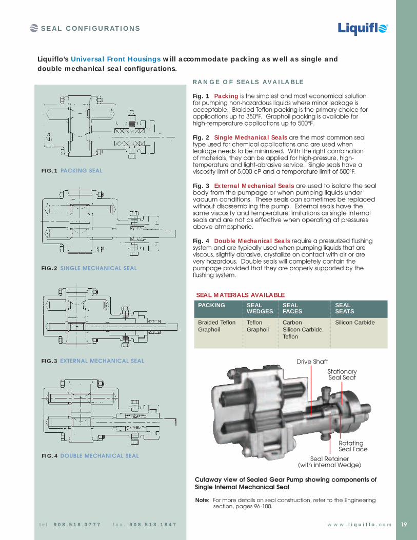
Liquiflo’s Universa l Front Housings w ill accommodate pack ing as w ell as single anddouble mechanica l sea l configura tions.
Fig. 1 Pack ing is the simplest and most economical solution for pumping non-hazardous liquids where minor leakage isacceptable. Braided Teflon packing is the primary choice forapplications up to 350°F. Graphoil packing is available for high-temperature applications up to 500°F.
Fig. 2 Single M echanica l Sea ls are the most common sealtype used for chemical applications and are used whenleakage needs to be minimized. With the right combination of materials, they can be applied for high-pressure, high-temperature and light-abrasive service. Single seals have aviscosity limit of 5,000 cP and a temperature limit of 500°F.
Fig. 3 Ex terna l M echanica l Sea ls are used to isolate the sealbody from the pumpage or when pumping liquids undervacuum conditions. These seals can sometimes be replacedwithout disassembling the pump. External seals have thesame viscosity and temperature limitations as single internalseals and are not as effective when operating at pressuresabove atmospheric.
Fig. 4 Double M echanica l Sea ls require a pressurized flushingsystem and are typically used when pumping liquids that areviscous, slightly abrasive, crystallize on contact with air or arevery hazardous. Double seals will completely contain thepumpage provided that they are properly supported by theflushing system.
FIG.1 PACKING SEAL
FIG.2 SINGLE MECHANICAL SEAL
FIG.4 DOUBLE MECHANICAL SEAL
FIG.3 EXTERNAL MECHANICAL SEAL
RA N G E O F SEA LS AV A I LA BLE
SEAL M ATERIALS AVAILABLE
PACKING SEAL SEAL SEAL WEDGES FACES SEATS
Braided Teflon Teflon Carbon Silicon CarbideGraphoil Graphoil Silicon Carbide
Teflon
Seal Retainer(with internal Wedge)
Drive Shaft
StationarySeal Seat
RotatingSeal Face
Cutaway view of Sealed Gear Pump showing components ofSingle Internal Mechanical Seal
t e l . 9 0 8 . 5 1 8 . 0 7 7 7 f a x . 9 0 8 . 5 1 8 . 1 8 4 7 w w w . l i q u i f l o . c o m
Note: For more details on seal construction, refer to the Engineering section, pages 96-100.

20 t e l . 9 0 8 . 5 1 8 . 0 7 7 7 f a x . 9 0 8 . 5 1 8 . 1 8 4 7 w w w . l i q u i f l o . c o m
Liquiflo pumps are easy to maintain or repair. Full-color installation and maintenance manuals are availablethat give clear, step-by-step instructions for disassembling and rebuilding the pumps. All manuals areavailable on the Liquiflo website and are also included with each pump, replacement cartridge or repair kitshipment. When pump maintenance or repair is necessary, the following options are available:
M aintenance & Repa ir Options:
A) Replace Pump – required when pump housings are worn to a point where acceptable performance cannot be restored by rebuilding pump with a repair kit or spare parts
B) Use Replacement Cartridge – this is the fastest way to replace a mag-drive pump that requires maintenance (see next page)
C) Use Repa ir Kit – if the housings are in good shape, pump performance can be restored to like-new condition by replacing the pump’s internal components (kits available for gear pumps only)
D) Replace Individua l Parts – all Liquiflo pump components can be purchased separately
Liquiflo Repa ir Kits conta in a ll components to completely rebuildyour Liquiflo Gear Pump to like-new condition
M AI N T E N AN C E & RE PAI R OP T I ON S
Simply place a “K” in front of the Liquiflo Pump Model Number.
How to Order Liquiflo Repa ir Kits:
REPAIR KIT CON TEN TS
• Gears • Bearings • O-Rings• Shafts • Wear Plates • Retaining Rings• Keys • Pins • Seals (if applicable)
Repa ir Kits a re ava ilable for a ll Liquiflo Gear Pum p Families
Why Use Repair Kits?
• Repair Kits simplify inventory and speed repair
• Repair Kits include gears and shafts pre-assembled
• Repair Kits ensure that all wear items in the pump will be replaced
• Repair Kits encourage replacement of non-reusable items such as O-rings and Retaining Rings
• Repair Kits allow pumps to be immediately rebuilt should a performance problem occur
• Repair Kits are a more efficient and cost-effective solution than using individual parts
Pump Model #: H5FS6PEEU000009Kit Model #: KH5FS6PEEU000009
Ex ample: Sealed Pump & Kit
21
M AI N T E N AN C E & RE PAI R OP T I ON S
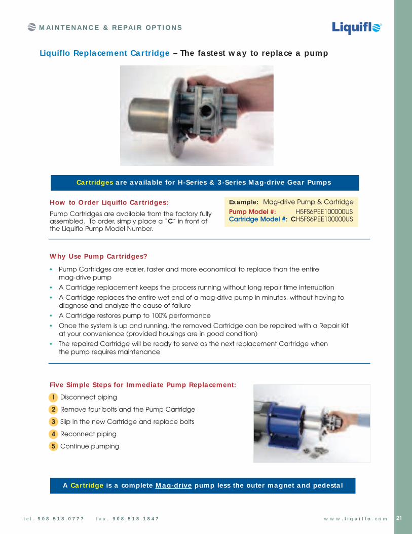
Cartridges a re ava ilable for H-Series & 3 -Series M ag-drive Gea r Pumps
Liquiflo Replacement Cartridge – The fastest w ay to replace a pump
How to Order Liquiflo Cartridges:
Pump Cartridges are available from the factory fully assembled. To order, simply place a “C” in front of the Liquiflo Pump Model Number.
W hy Use Pump Cartridges?
• Pump Cartridges are easier, faster and more economical to replace than the entire mag-drive pump
• A Cartridge replacement keeps the process running without long repair time interruption
• A Cartridge replaces the entire wet end of a mag-drive pump in minutes, without having to diagnose and analyze the cause of failure
• A Cartridge restores pump to 100% performance
• Once the system is up and running, the removed Cartridge can be repaired with a Repair Kit at your convenience (provided housings are in good condition)
• The repaired Cartridge will be ready to serve as the next replacement Cartridge when the pump requires maintenance
Five Simple Steps for Immedia te Pump Replacement:
1 Disconnect piping
2 Remove four bolts and the Pump Cartridge
3 Slip in the new Cartridge and replace bolts
4 Reconnect piping
5 Continue pumping
A Cartridge is a complete M ag-drive pump less the outer magnet and pedesta l
t e l . 9 0 8 . 5 1 8 . 0 7 7 7 f a x . 9 0 8 . 5 1 8 . 1 8 4 7 w w w . l i q u i f l o . c o m
Pump Model #: H5FS6PEE100000USCartridge Model #: CH5FS6PEE100000US
Ex ample: Mag-drive Pump & Cartridge

22 t e l . 9 0 8 . 5 1 8 . 0 7 7 7 f a x . 9 0 8 . 5 1 8 . 1 8 4 7 w w w . l i q u i f l o . c o m
Threaded Ports
All Liquiflo pumps are available with NPT or BSPT ports.
OP T I ON S & AC C E SSORI E S
PORT CON N ECTION S
Raised-Face (RF) Flanges
Most Liquiflo pumps are available with flanged ports to simplify pipingconnections. Available flanges are ANSI150# or 300# , DIN PN16 and JIS 10K.
Sanita ry Fittings
Tri-clamp sanitary fittings provide aconvenient alternative to threaded orflanged port connections.
TEM PERATURE CON TROL
Tempera ture Control (Hea t) Jackets(Clamp-on Design)
Liquiflo’s Temperature Control Jacket can maintain the pump at either elevated or reducedtemperatures. It is commonly used when pumpingliquids that solidify or become difficult to pumpwhen the temperature decreases. The jacket bodyis made of Cast Aluminum; the connectors aremade of Stainless Steel.
Dua l Kan ®
(Double Wa ll Conta inment Can)
Liquiflo’s patented Dual Kan® controls the temperature of the back end of amagnetically-driven pump by circulating a heating or cooling fluid through thecontainment can. This is ideal for applications requiring precise and uniform temperature control. The Dual Kan® will compensate for increases in temperature due to eddy current losses from the mag-drive coupling.(See Engineering section, page 92.)
Note: Available only for specific pump sizes. Consult Factory.

23
OP T I ON S & AC C E SSORI E S
S-AdapterThe S-Adapter is used with the Liquiflo MC-Pedestal tolong-couple mag-drive pumps. It isolates the pump from the motor and can be used when long-coupling motors or drives that do not have a C-face mounting. The maximumtemperature rating is 250°F (~120°C).
COUPLIN G & M OUN TIN G
Pow er FrameThe Liquiflo Power Frame is used to long-couple mag-drivegear pumps or the Centry® Series centrifugal pumps, for use in high-temperature applications – up to the pump’s maximumtemperature rating. Its integral cooling jacket keeps the bearingsystem of the pedestal cool even when it is coupled to a pumpoperating at extremely high temperature.
Base Pla te M ountingMost Liquiflo pumps are available with base-mounts tosimplify installation. Liquiflo also offers base-mounted unitswith or without the motor pre-installed. Stainless Steel andEpoxy-painted Channel Steel base plates are available.
RELIEF VALVES
Positive displacement pumps should be installed with a Relief Valve in the discharge line to protect the pump and pipingfrom any type of line blockage, including the inadvertent closingof an isolation valve. Liquiflo manufactures two sizes of reliefvalves in both 316 SS and Alloy-C. (See Engineering section, page 95, for more details.)
Mechanical couplings, coupling guards, risers,base plates, adapters, brackets and pedestals,can all be purchased separately.
ACCESSORIES
Liquiflo Gear Pumps can be furnished from the factory with anytype of motor, variable speed drive or gear reducer.
M ISCELLAN EOUS OPTION S
S-Adapter
Power Frame
Base-Mounted Unit includescoupling guard, not shown.
t e l . 9 0 8 . 5 1 8 . 0 7 7 7 f a x . 9 0 8 . 5 1 8 . 1 8 4 7 w w w . l i q u i f l o . c o m
Base Plate
Motor Adapter Plate
Coupling Guard
MechanicalCoupling
Pedestal
Riser
Note: For more details on Coupling & Mounting, see the Engineering section, page 94.
24 t e l . 9 0 8 . 5 1 8 . 0 7 7 7 f a x . 9 0 8 . 5 1 8 . 1 8 4 7 w w w . l i q u i f l o . c o m
There’s only one true test of pump performance: The Field Test
The following case histories (in alphabetical order) attest to the versatility and dependability of Liquiflogear pumps in some of the most difficult and challenging field applications. When you absolutelyhave to depend on a pump, isn’t it good to know that you can rely on the kind of performance thatLiquiflo pumps delivered in these cases?
Carbon-13 Ex traction Carbon-13, a stable isotope often called “the Gold Sample” is used in medical,biological, agricultural and environmental industries. With a value of about $700per gram, carbon-13 is extracted in a complicated and difficult operation thatrequires carefully controlled chemical reaction and condensation processes. This poses a particular challenge to the pumps that must continually circulate the process liquids at stable, precisely controlled rates.
A carbon-13 plant constructed in China evaluated centrifugal, diaphragm and locally produced gear pumps. None could provide the system control orreliability required – but Liquiflo could. The facility specified 20 sets of Liquiflo
gear pumps, equipped with frequency converters to accurately control flow rates. The chief engineerof the plant compared these Liquiflo pumps to a human heart in terms of their function andimportance to the operation. The pumps have operated for years without a single failure, and theirability to deliver precise, pulse-free pumping rates has allowed the entire plant to operate at highefficiency.
AP P LI C AT I ON C ASE H I ST ORI E S
Applica tion Case Histories for Liquiflo Gear Pumps
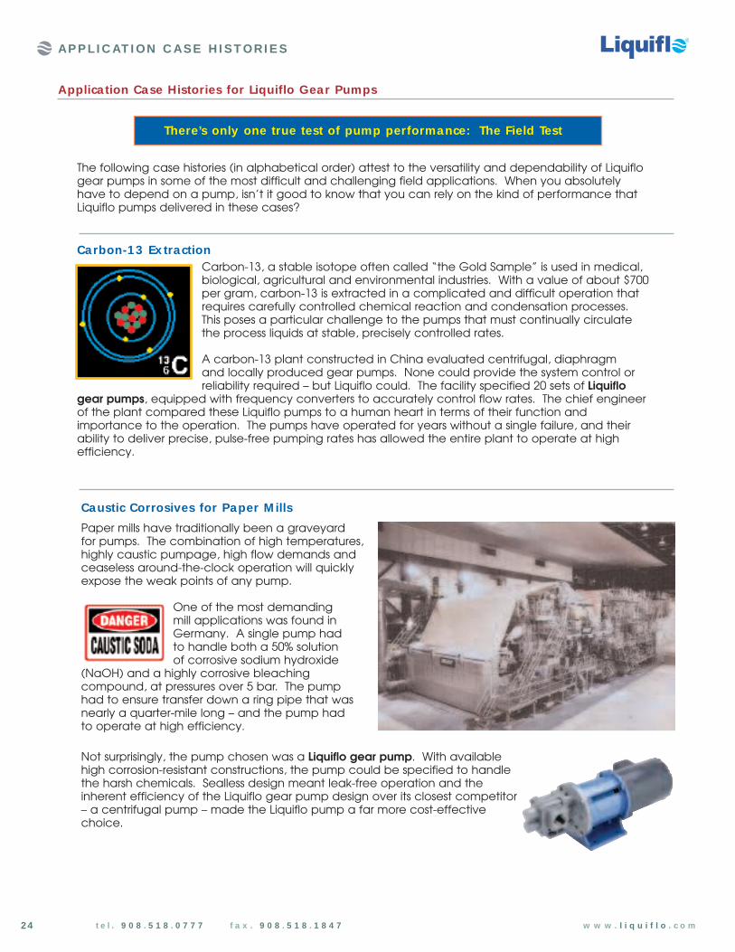
Caustic Corrosives for Paper M ills
Paper mills have traditionally been a graveyard for pumps. The combination of high temperatures,highly caustic pumpage, high flow demands andceaseless around-the-clock operation will quicklyexpose the weak points of any pump.
One of the most demanding mill applications was found inGermany. A single pump had to handle both a 50% solution of corrosive sodium hydroxide
(NaOH) and a highly corrosive bleachingcompound, at pressures over 5 bar. The pump had to ensure transfer down a ring pipe that wasnearly a quarter-mile long – and the pump had to operate at high efficiency.
Not surprisingly, the pump chosen was a Liquiflo gear pump. With availablehigh corrosion-resistant constructions, the pump could be specified to handlethe harsh chemicals. Sealless design meant leak-free operation and theinherent efficiency of the Liquiflo gear pump design over its closest competitor– a centrifugal pump – made the Liquiflo pump a far more cost-effectivechoice.

25
AP P LI C AT I ON C ASE H I ST ORI E S
Chemica l M etering for Water Purifica tion Plants The Metropolitan Water District of Southern California is the largestwater system in the world, responsible for providing billions of gallonsof safe, potable water to tens of millions of people.
Over the past twenty years, the Water District has tried a variety of chemical metering pumps – and found that all had limitations.Diaphragm pumps and progressive cavity pumps turned out to be maintenance-intensive, with a high cost of ownership. Many typesof gear pumps were tried – but they lacked the necessary accuracyand had high wear rates.
Then, in the early 1990’s, the District tried its first Liquiflo sealless mag-drive gear pumps. Even with variable speed drives and special motor engineering, the Liquiflo pumps were about half the price of the pumps they replaced. The performance of this combination has been so exceptional that the District has replaced over 124 of its previous pumps with this Liquiflo design.
Fumigants & Pesticides A leading US manufacturer of agricultural fumigants and pesticides had a problem with their currentpumps. They suffered from accelerated internal wear and early failure that was costing thousands ofdollars per month in replacements and downtime.
Their pump representative suggested a switch over to the Liquiflo H-Series gear pumps with a superior selection of internal componentsthan the current pumps, which gave the Liquiflo pumps a muchbroader reach of chemical compatibility.
The H-Series pumps promised to deliver increased pump life andapplication longevity – and they delivered on that promise. In the first calendar year after installation, the customer saw a $27,000 savings in parts and pump replacements, with a 52% decrease inoverall pump downtime.
M olten Sulfur Sulfur is a nonmetal solid element at room conditions. It is used to produce sulfuric acid as well as a variety of other importantsulfur-based compounds and products.
Molten sulfur is one of the most difficult chemicals to pump. First, highoperating temperatures are needed to keep a normally solid elementin a liquid state. Then, precise temperature levels must be maintained
– small variations lead to wide changes in viscosity. If the sulfur gets too cold, it sets up in the pump andpiping, requiring intensive, expensive downtime; too hot, and it polymerizes, turning into a near solid.
So it takes and extraordinary pump to transfer and meter sulfur – and that’s precisely what Liquiflo supplied to its customersfor this difficult application. Liquiflo’s highly specialized gearpump design uses a magnetic sealless drive, a heating jacket onthe pump end to maintain temperature, and a patented DualKan enclosure. The Dual Kan is fitted over the driven magneticarea, so sulfur can be melted before the pump is started. Thesefeatures allow the sulfur to stay within a very tight temperatureband. As a result, the pump is able to deliver accurate, pulse-free flows; and, liquid temperatures arekept within the optimum range, allowing trouble-free operation.
t e l . 9 0 8 . 5 1 8 . 0 7 7 7 f a x . 9 0 8 . 5 1 8 . 1 8 4 7 w w w . l i q u i f l o . c o m
Applica tion Case Histories for Liquiflo Gear Pumps

26
PFC Coolants for Tempera ture Controllers Perfluorocarbon (PFC) coolants are a popular alternative to environmentallyhazardous chlorinated solvents. One specialty application for PFC coolants is inhigh-performance chillers used for stringent semiconductor applications. The chillersystems require highly reliable temperature control, so every part of the system mustbe absolutely dependable.
This is why a customer’s system designers picked the Liquiflo gear pump to circulate the PFC coolant through the system. To accurately controltemperatures, the coolant must be constantly
circulating at precisely metered speeds – and absolutely no leakage of theexpensive coolant could be tolerated. The Liquiflo mag-drive gear pump,specifically engineered to maximize reliability, was the only pump projectengineers felt could deliver the essential uptime required for this application.Chiller systems using Liquiflo gear pumps have seen measured MTBM (meantime between maintenance) in excess of 40,000 hours!
AP P LI C AT I ON C ASE H I ST ORI E S
Polymer Flocculant for Water Trea tment
A wire technology company was using a progressive cavity pump to addmetered doses of polymer flocculant to a clarifier water treatment system.The flow was highly viscous, and spiked with lumps of dry polymer. Theprogressive cavity pump regularly sheared pins, and suffered extensivestator and rotor wear. Seals and packing glands needed constantmaintenance. Plant management replaced it with a Liquiflo gear pump.Using mechanical seals and Teflon bearings, the Liquiflo pump delivered five years of trouble-free service, 24 hours a day, 7 days a week – with onlyoccasional suction and discharge line cleaning needed to maintain like-new performance.
Shear-Sensitive Polymers
A specialty chemical company had narrowed its search for a polymer transferpump down to either a Liquiflo gear pump or a progressive cavity (PC) pump.The gear pump offered reliability and ease of maintenance, but the progressivecavity pump was known for its low-shear operation – a critical element, sinceshear could adversely influence the effectiveness of the high-quality polymersolution.
So they evaluated bothpumps with the polymersolutions, over a range ofspeeds and pressures. Using change in viscosity to
measure relative shear (the higher the viscosity, thelower the shear), they discovered that the Liquiflo gearpump actually induced less shear than the progressivecavity pump. Based on these findings, the chemicalcompany made Liquiflo gear pumps the standardcomponent on their polymer solution packages.
0 10 20 30 40 50 60
350
300
250
200
Pump Speed (Motor Hz)
VISCOSITY vs. SHEAR RATE
Gear
PC
Vis
cosi
ty (
cP)
Suggested operatingpoint for gear pump
Maximum operatingspeed for gear pump
t e l . 9 0 8 . 5 1 8 . 0 7 7 7 f a x . 9 0 8 . 5 1 8 . 1 8 4 7 w w w . l i q u i f l o . c o m
Applica tion Case Histories for Liquiflo Gear Pumps

Sodium Hypochlorite M etering for Wastew ater Trea tmen t PlantsA Texas wastewater treatment plant had trouble with the pumps itused to supply variable flows of 9-11% sodium hypochlorite (NaOCl)to its processes. The tubular diaphragm pumps suffered rupturesthat spewed the corrosive chemical into the plant. In addition, the flow suffered from pulses and surges that threatened to upsetprocess balances.
A Liquiflo gear pump was then tried as a replacement. Configuredwith a mag-drive for sealless, leak-free operation, and titaniumconstruction for corrosion resistance, the Liquiflo pump wasdesigned to provide greater reliability while delivering a range ofpulse-free, easy-to-measure media flows.
After 15 months of trouble-free service, the plant maintenance managerconsidered the Liquiflo solution to be a complete success – in terms of bothperformance and economy. Metered flows have been far more precise; reliabilityhas been absolute; and, because the Liquiflo pumps eliminated pulsing, they alsoeliminated the need for dampeners and additional pipe supports.
A P P LI C AT I ON C ASE H I ST ORI E S
Solvents for Ex traction of Organic Chemica ls
A chemical company specializing in the extraction of valuableorganic chemicals required large amounts of chlorinated and non-chlorinated solvents in their processes. These thin, non-lubricating fluids have low viscosities and low boiling points, sothey’re very difficult to pump, and very susceptible to leaks.
The company chose to use Liquiflo sealless mag-drive gearpumps with coated shafts for their applications with low NPSH,low flows or precise metering requirements. The gear pumps were equipped with air motors, which provided an effective and inexpensiveexplosion-proof system with variable speed capability. The Liquiflo gear pumps performed exceedingly well in this highly challenging environment.
Sulfuric Acid
Sulfuric acid (H2SO4) is the world’s most produced chemical. It is used in the production of batteries, dyes, drugs, insecticides,plastics, steel, paper, drain cleaners, explosives, detergents,fertilizers and many other materials. Sulfuric acid is also used forwater treatment, ore processing, oil refining, dehydrating and asa catalyst for chemical reactions.
Aqueous sulfuric acid is typically pumped over a wide range of concentration – fromdilute to 100% concentrated. The viscous and corrosive properties of sulfuric acid are highly dependenton concentration and temperature. The hygroscopic and exothermic nature of sulfuric acid can causeits concentration and temperature to change, altering its properties. These facts make sulfuric acida difficult chemical to handle.
Since sulfuric acid is highly important, corrosive and hazardous, it is no surprise that this chemical is one of Liquiflo’s most common pumping applications. A wide selection of standard options and corrosion-resistant materials allow Liquiflo gear pumps to be easily custom-engineered to handle the variousproperties of sulfuric acid.
27t e l . 9 0 8 . 5 1 8 . 0 7 7 7 f a x . 9 0 8 . 5 1 8 . 1 8 4 7 w w w . l i q u i f l o . c o m
Applica tion Case Histories for Liquiflo Gear Pumps

t e l . 9 0 8 . 5 1 8 . 0 7 7 7 f a x . 9 0 8 . 5 1 8 . 1 8 4 7 w w w . l i q u i f l o . c o m28
L I Q U I F L O C H E M I C A L P R O C E S S I N G P U M P S
H - SE RI E SHEAVY-DUTY INDUSTRIAL GEAR PUM PS
H-Series
Up to 225 PSI differentia l pressure
The H-Series Gear Pumps were designed as an upgrade to Liquiflo’s original 3-Series. With similar outside dimensions and capacities, the H-Series incorporates larger shafts and bearings, allowing them to handle higher pressures with extended service life. The H-Series pumps are available in Sealed and Mag-Drive versions with flows up to approximately 30 GPM and differential pressures up to 225 PSI.* * 300 PSI possible on some models. Contact factory.
The H-Series is recommended for all new applications as well as an upgrade to any existing 3-Series installations.
H-Series Specifica tions
* Higher viscosities possible. Contact factory. LC = Long-Coupled CC = Close-Coupled
SEALED H1F H3F H5R H5F H7N H7R H7FMAG-DRIVE H1F-MC H3F-MC H5R-MC H5F-MC H7N-MC H7R-MC H7F-MC
Max Flow Rate 0 .5 GPM (1 .9 LPM) 1 .4 GPM (5 .3 LPM) 2 .4 GPM (9 .1 LPM) 3 .4 GPM (13 LPM) 5 .4 GPM (20 LPM) 8 .6 GPM (33 LPM) 10 .7 GPM (40 .5 LPM)
Max Diff. Press. 225 PSI (15.5 BAR) 225 PSI (15.5 BAR) 225 PSI (15.5 BAR) 225 PSI (15.5 BAR) 225 PSI (15.5 BAR) 225 PSI (15.5 BAR) 225 PSI (15.5 BAR)
Max Discharge 300 PSI (20.7 BAR) 300 PSI (20.7 BAR) 300 PSI (20.7 BAR) 300 PSI (20.7 BAR) 225 PSI (15.5 BAR) 225 PSI (15.5 BAR) 225 PSI (15.5 BAR)
Max Temp. 500 ˚F (260 ˚C) 500 ˚F (260 ˚C) 500 ˚F (260 ˚C) 500 ˚F (260 ˚C) 500 ˚F (260 ˚C) 500 ˚F (260 ˚C) 500 ˚F (260 ˚C)
Max Viscosity 100,000* CPS 100,000* CPS 100,000* CPS 100,000* CPS 100,000* CPS 100,000* CPS 100,000* CPS
Max Speed 1750 RPM 1750 RPM 1750 RPM 1750 RPM 1750 RPM 1750 RPM 1750 RPM
NPSHR @ Max Speed 3 FT (0.9M) 2 FT (0.6M) 2 FT (0.6M) 2 FT (0.6M) 5.2 FT (1.6M) 5.2 FT (1.6M) 5.2 FT (1.6M)
Weight Sealed, LC 2.5 LBS (1.1 KGS) 2.5 LBS (1.1 KGS) 3.5 LBS (1.6 KGS) 3.5 LBS (1.6 KGS) 6.5 LBS (2.9 KGS) 6.5 LBS (2.9 KGS) 6.5 LBS (2.9 KGS)
Sealed, CC 23 LBS (10 KGS) 23 LBS (10 KGS) 24 LBS (11 KGS) 24 LBS (11 KGS) 29 LBS (13 KGS) 29 LBS (13 KGS) 29 LBS (13 KGS)
Mag-Drive, CC 31 LBS (14 KGS) 31 LBS (14 KGS) 32 LBS (15 KGS) 32 LBS (15 KGS) 36 LBS (16 KGS) 36 LBS (16 KGS) 36 LBS (16 KGS)
SEALEDLong-Coupled
MAG-DRIVEor SEALEDClose-Coupled
TM
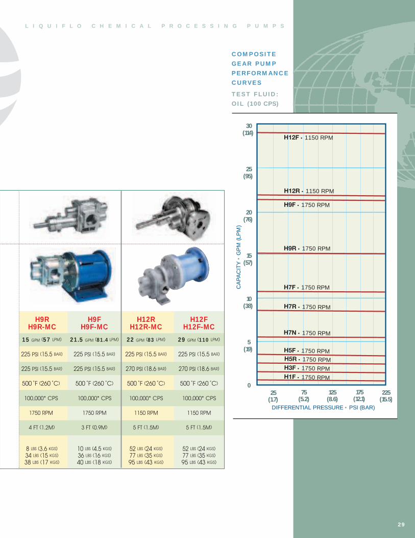
C OM P OSI T E
GE AR P U M P
P E RFORM AN C E
C U RVE S
T E ST FLU I D :
OI L (100 CPS)
L I Q U I F L O C H E M I C A L P R O C E S S I N G P U M P S
29
H9R H9F H12R H12FH9R-MC H9F-MC H12R-MC H12F-MC
15 GPM (57 LPM) 21 .5 GPM (81 .4 LPM) 22 GPM (83 LPM) 29 GPM (110 LPM)
225 PSI (15.5 BAR) 225 PSI (15.5 BAR) 225 PSI (15.5 BAR) 225 PSI (15.5 BAR)
225 PSI (15.5 BAR) 225 PSI (15.5 BAR) 270 PSI (18.6 BAR) 270 PSI (18.6 BAR)
500 ˚F (260 ˚C) 500 ˚F (260 ˚C) 500 ˚F (260 ˚C) 500 ˚F (260 ˚C)
100,000* CPS 100,000* CPS 100,000* CPS 100,000* CPS
1750 RPM 1750 RPM 1150 RPM 1150 RPM
4 FT (1.2M) 3 FT (0.9M) 5 FT (1.5M) 5 FT (1.5M)
8 LBS (3.6 KGS) 10 LBS (4.5 KGS) 52 LBS (24 KGS) 52 LBS (24 KGS)
34 LBS (15 KGS) 36 LBS (16 KGS) 77 LBS (35 KGS) 77 LBS (35 KGS)
38 LBS (17 KGS) 40 LBS (18 KGS) 95 LBS (43 KGS) 95 LBS (43 KGS)
175(12.1)
125(8.6)
DIFFERENTIAL PRESSURE • PSI (BAR)
CA
PA
CIT
Y•
GP
M(L
PM
)
H7N • 1750 RPM
H3F • 1750 RPM
225(15.5)
(114)
(95)
(76)
(57)
(38)
(19)
75(5.2)
H5F • 1750 RPM
H7R • 1750 RPM
H7F • 1750 RPM
H12R • 1150 RPM
H12F • 1150 RPM
25(1.7)
H9F • 1750 RPM
H9R • 1750 RPM
30
25
20
15
10
5
0
H5R • 1750 RPM
H1F • 1750 RPM
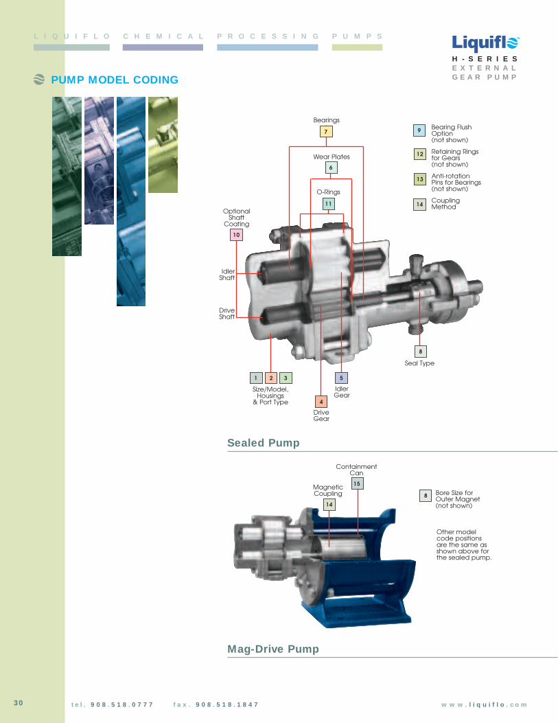
30
PUMP MODEL CODING
t e l . 9 0 8 . 5 1 8 . 0 7 7 7 f a x . 9 0 8 . 5 1 8 . 1 8 4 7 w w w . l i q u i f l o . c o m
L I Q U I F L O C H E M I C A L P R O C E S S I N G P U M P S
H - S E R I E SE X T E R N A LG E A R P U M P
Bearings
Wear Plates
IdlerGear
Seal Type
Size/Model,Housings
& Port Type
MagneticCoupling
DriveGear
DriveShaft
IdlerShaft
OptionalShaft
Coating
1 2 3
4
5
6
7
8
10
11
12
13
O-Rings
14
8 Bore Size forOuter Magnet(not shown)
Bearing FlushOption(not shown)
Retaining Ringsfor Gears(not shown)
Anti-rotationPins for Bearings(not shown)
CouplingMethod
15
ContainmentCan
Other modelcode positions are the same asshown above forthe sealed pump.
9
Sealed Pump
Mag-Drive Pump
14
TM
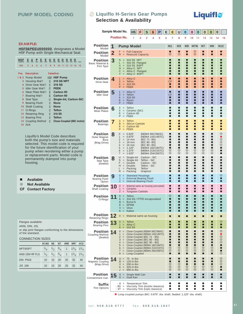
31t e l . 9 0 8 . 5 1 8 . 0 7 7 7 f a x . 9 0 8 . 5 1 8 . 1 8 4 7
H1 H3 H5 H7N H7 H9 H12
F = Full Capacity n n n U n n n
R = Reduced Capacity U U n U n n n
S = 316 SS NPT n n n n n n n
L = 316 SS Flanged n n n n n n n
X = 316 SS BSPT n n n n n n n
H = Alloy-C NPT n n n n n n n
C = Alloy-C Flanged n n n n n n n
Y = Alloy-C BSPT n n n n n n n
1 = Alloy-C n n n n n n n
3 = Teflon CF n n n n n n
6 = 316 SS n n n n n n n
P = PEEK n n n n n n n
1 = Alloy-C n n n n n n n
3 = Teflon CF n n n n n n
6 = 316 SS n n n n n n n
8 = Ryton n n n n n n n
P = PEEK n n n n n n n
3 = Teflon n n n n n n n
4 = Ceramic (SiC) n n n n n n n
E = Carbon 60 n n n n n n n
P = PEEK n n n n n n n
3 = Teflon n n n n n n n
B = Silicon Carbide n n n n n n n
E = Carbon 60 n n n n n n n
P = PEEK n n n n n n n
0 = 0.625” (NEMA 56C/56HC) n n n n n n U1 = 0.875” (NEMA 143/145TC) n n n n n n n
2 = 14 mm (IEC 71 - B5) n n n n n n U3 = 19 mm (IEC 80 - B5) n n n n n n U4 = 24 mm (IEC 90 - B5) n n n n n n U5 = 1.125” (NEMA 182/184TC) n n n n n n n
6 = 1.375” (NEMA 213/215TC) U U U U U U n
7 = 1.625” (NEMA 254/256TC) U U U U U U n
U = Single-Int Carbon - SiC n n n n n n n
S = Single-Int Teflon - SiC n n n n n n n
F = Double Carbon - SiC n n n n n n n
H = Double Teflon - SiC n n n n n n n
L = Packing Teflon n n n n n n n
R = Packing Graphoil n n n n n n n
0 = Standard Housings n n n n n n U1 = External Bearing Flush n n n n n n n
2 = Internal Bearing Flush n n n n n n n
0 = Material same as housing (uncoated) n n n n n n n
1 = Ceramic n n n n n n n
2 = Tungsten Carbide n n n n n n n
0 = Teflon U n n n n n n
6 = 316 SS / PTFE encapsulated n n n n n n n
B = Buna-N n n n n n n n
E = EPDM n n n n n n n
V = Viton n n n n n n n
K = Kalrez n n n n n n n
0 = Material same as housing n n n n n n n
0 = Teflon n n n n n n U1 = Alloy-C n n n n n n n
6 = 316 SS n n n n n n n
0 = Close-Coupled (NEMA 56C/56HC) n n n n n n U1 = Close-Coupled (NEMA 143/145TC) n n n n n n n
2 = Close-Coupled (IEC 71 - B5) n n n n n n U3 = Close-Coupled (IEC 80 - B5) n n n n n n U4 = Close-Coupled (IEC 90 - B5) n n n n n n U5 = Close-Coupled (NEMA 182/184TC) n n n n n n n
6 = Close-Coupled (NEMA 213/215TC) U U U U U U n
7 = Close-Coupled (NEMA 254/256TC) U U U U U U n
9 = Long-Coupled n n n n n n U
U = 75 in-lbs n n n n n n UB = 120 in-lbs n n n n n n UV = 200 in-lbs U U n n n n UK = 325 in-lbs U U U U U U n
J = 650 in-lbs U U U U U U n
S = Single Wall Can n n n n n n n
D = Dual Kan n n n n n n n
- 8 = Temperature Trim n n n n n n n
- 9D = Viscosity Trim (double clearance) n n n n n n n
- 9T = Viscosity Trim (triple clearance) n n n n n n n
n Long-coupled pumps (MC: 0.875” dia. shaft; Sealed: 1.125” dia. shaft)
2PositionModel
3PositionBasic Material &
Port Type
4PositionDrive Gear
5PositionIdler Gear
6PositionWear Plates
7PositionBearings
8PositionOuter Magnet
Bore (Mag-Drive)
9PositionBearing Flush
Option
10PositionShaft Coating
11PositionO-Rings
12PositionRetaining Rings
13PositionBearing Pins
14PositionMagnetic Coupling
(Mag-Drive)
15PositionContainment Can
Pump Model1PositionModel
Sample Model No.
Position No.
H5 F S 6 P E E U 0 0 0 0 01 2 3 4 5 6 7 8 9 10 11 12 13 14 15
PUMP MODEL CODING
H5F S 6 P E E U 0 0 0 0 0 0
Pump Model H5F H5F Pump
Housing Mat’l S 316 SS NPT
Drive Gear Mat’l 6 316 SS
Idler Gear Mat’l P PEEK
Wear Plate Mat’l E Carbon 60
Bearing Mat’l E Carbon 60
Seal Type U Single-Int, Carbon-SiC
Bearing Flush 0 None
Shaft Coating 0 None
O-Rings 0 Teflon
Retaining Ring 0 316 SS
Bearing Pins 0 Teflon
Coupling Method 0 Close-Coupled (56C motor)
N/A
1&2 3 4 5 6 7 8 9 10 11 12 13 14 15
1 & 2
3
4
5
6
7
8
9
10
11
12
13
14
15
Pos. Description Selection
EXAM PLE:H5FS6PEEU000000, designates a ModelH5F Pump with Single Mechanical Seal.
Liquiflo’s Model Code describesboth the pump’s size and materialsselected. This model code is required for the future identification of yourpump when reordering either a pump or replacement parts. Model code ispermanently stamped into pumphousing.
n Available
U Not Available
CF Contact Factory
Liquiflo H-Series Gear PumpsSelection & Availability
Flanges available:
ANSI, DIN, JIS, or slip joint flanges conforming to the dimensionsof the standard.
CONNECTION SIZES
H1/H3 H5 H7 H9R H9F H12
NPT/BSPT 1/4 1/2 3/4 1 11/4 11/4
ANSI 150# RF FLG 1/2 1/2 3/4 1 11/4 11/2
DIN PN16 10 15 20 25 32 40
JIS 10K 10 15 20 25 32 40
8PositionSeal Type
(Sealed)
SuffixTrim Options
14PositionCoupling Method
(Sealed)
0
TM

DIFFERENTIAL PRESSURE (PSI)
0.6
0.5
0.4
0.3
0.2
0.1
0100755025 1250
0.18
0.15
0.12
0.09
0.06
0.03
0
1750
1450
1150
900
PO
WE
R(B
HP
)
FLO
W(G
PM
)
600
1750
600
LPM
2.0
1.8
1.6
1.4
1.2
1.0
0.8
0.6
0.4
0.2
0
0 1 2 3 4 5 6 7 8 9
BAR
100 CPS Fluid (Oil)
1 CPS Fluid (Water)
P E R F O R M A N C E C U R V E S
H 1 F S E A L E DH 1 F - M C M A G - D R I VE
H1F Sealed, Long-Coupled
H1F-MC & H1F Sealed, Close-Coupled
Dimensional Data (inches)
Dimensional Data (inches)
4.50 PORT
CL
9.31
7.25
5.94
3.50 3.06 2.50 2.50
6.50
2.68
1.34
0.41 DIA.THRU
4.00 SHAFT
CL
TM
NOTES: (1) Add .31 inches for Bearing Flush Plugs.(2) Minimum dimension.
SEAL CONFIGURATIONSSINGLE & DOUBLE P ACKING
DIMENSION MECHANICAL SEALSCP (1 ) 6 .94 6 .94
L 5 .44 5 .44N 1 .12 1 .19 (2 )
H - S E R I E SG E A R P U M P
0.6
0.5
0.4
0.3
0.2
0.1
0
1750
1450
1150
900 FLO
W (
GP
M)
600
1750
LPM
2.0
1.8
1.6
1.4
1.2
1.0
0.8
0.6
0.4
0.2
0
0.24
0.20
0.16
0.12
0.08
0.04
0
DIFFERENTIAL PRESSURE (PSI)
100755025 2000 175150125 225
0 2 4 6 8
BAR10 12 14 16
PO
WE
R (
BH
P)
600
t e l . 9 0 8 . 5 1 8 . 0 7 7 7 f a x . 9 0 8 . 5 1 8 . 1 8 4 732
PORT SIZE 1/4” NPT/BSPT or 1/2” FLG
MAX FLOW 0.5 GPM; 1.9 LPM
MAX DIFFERENTIAL PRESSURE 225 PSI; 15.5 BAR
MAX DISCHARGE PRESSURE 300 PSI; 20.7 BAR
MAX TEMPERATURE 500˚F; 260˚C
MIN TEMPERATURE -40˚F; -40˚C
MAX VISCOSITY 100,000* CPS
NPSHR @ 1750 RPM 3 FT; 0.9 M
LIFT (DRY) 0.5 FT; 0.15 M
WEIGHT (without motor)SEALED, Long-Coupled 2.5 LBS; 1.1 KGSSEALED, Close-Coupled 23 LBS; 10 KGSMAG-DRIVE, Close-Coupled 31 LBS; 14 KGS
1.34
2.75
1.38
3.19
2.69
0.19
0.27 DIA. THRU
L
CP
N
0.63
0.375DIA.
SHAFT
2.68
.875
1.375PORT
CL
* Higher viscosities possible. Contact factory.
Sealed,Long-Coupled
Sealed or Mag-Drive,Close-Coupled
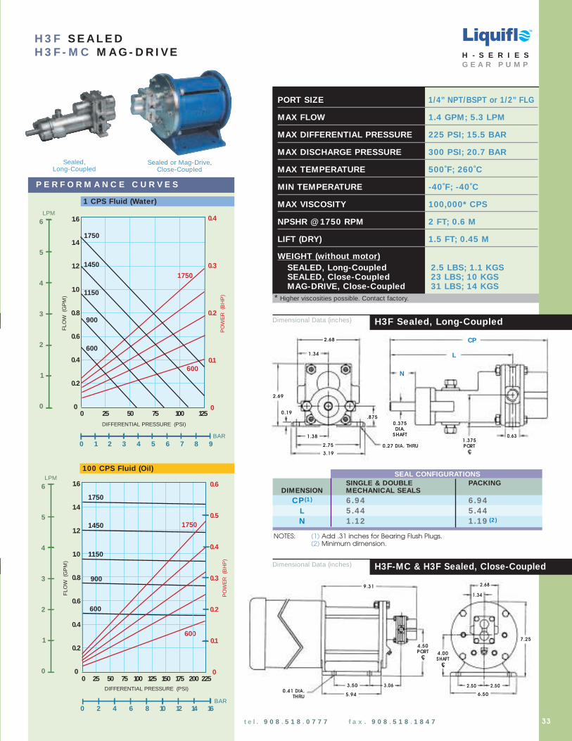
PORT SIZE 1/4” NPT/BSPT or 1/2” FLG
MAX FLOW 1.4 GPM; 5.3 LPM
MAX DIFFERENTIAL PRESSURE 225 PSI; 15.5 BAR
MAX DISCHARGE PRESSURE 300 PSI; 20.7 BAR
MAX TEMPERATURE 500˚F; 260˚C
MIN TEMPERATURE -40˚F; -40˚C
MAX VISCOSITY 100,000* CPS
NPSHR @ 1750 RPM 2 FT; 0.6 M
LIFT (DRY) 1.5 FT; 0.45 M
WEIGHT (without motor)SEALED, Long-Coupled 2.5 LBS; 1.1 KGSSEALED, Close-Coupled 23 LBS; 10 KGSMAG-DRIVE, Close-Coupled 31 LBS; 14 KGS
DIFFERENTIAL PRESSURE (PSI)
1.6
1.4
1.2
1.0
0.8
0.6
0.4
0.2
0755025 1000
1750
1450
900
PO
WE
R(B
HP
)
FLO
W(G
PM
)
1750
600
600
1150
0.4
0.3
0.2
0.1
0125
0 1 2 3 4 5 6 7 8 9BAR
LPM
6
5
4
3
2
1
0
H 3 F S E A L E DH 3 F - M C M A G - D R I VE
DIFFERENTIAL PRESSURE (PSI)
100755025 2000
1750
1450
1150
900
PO
WE
R(B
HP
)
FLO
W(G
PM
)
600
1750
1.6
1.4
1.2
1.0
0.8
0.6
0.4
0.2
0
600
0.6
0.5
0.4
0.3
0.2
0.1
0175150125 225
0 2 4 6 8BAR
10 12 14 16
LPM
6
5
4
3
2
1
0
100 CPS Fluid (Oil)
P E R F O R M A N C E C U R V E S
1 CPS Fluid (Water)
Dimensional Data (inches)
Dimensional Data (inches)
H3F Sealed, Long-Coupled
H3F-MC & H3F Sealed, Close-Coupled
TM
1.34
2.75
1.38
3.19
2.69
0.19
0.27 DIA. THRU
L
CP
N
0.63
0.375DIA.
SHAFT
2.68
.875
4.50 PORT
CL
9.31
7.25
5.94
3.50 3.06 2.50 2.50
6.50
2.68
1.34
0.41 DIA.THRU
4.00 SHAFT
CL
1.375PORT
CL
H - S E R I E SG E A R P U M P
* Higher viscosities possible. Contact factory.
33t e l . 9 0 8 . 5 1 8 . 0 7 7 7 f a x . 9 0 8 . 5 1 8 . 1 8 4 7
NOTES: (1) Add .31 inches for Bearing Flush Plugs.(2) Minimum dimension.
SEAL CONFIGURATIONSSINGLE & DOUBLE P ACKING
DIMENSION MECHANICAL SEALSCP (1 ) 6 .94 6 .94
L 5 .44 5 .44N 1 .12 1 .19 (2 )
Sealed,Long-Coupled
Sealed or Mag-Drive,Close-Coupled

PORT SIZE 1/2” NPT/BSPT/FLG
MAX FLOW 2.4 GPM; 9.1 LPM
MAX DIFFERENTIAL PRESSURE 225 PSI; 15.5 BAR
MAX DISCHARGE PRESSURE 300 PSI; 20.7 BAR
MAX TEMPERATURE 500˚F; 260˚C
MIN TEMPERATURE -40˚F; -40˚C
MAX VISCOSITY 100,000* CPS
NPSHR @ 1750 RPM 2 FT; 0.6 M
LIFT (DRY) 2 FT; 0.6 M
WEIGHT (without motor)SEALED, Long-Coupled 3.5 LBS; 1.6 KGSSEALED, Close-Coupled 24 LBS; 11 KGSMAG-DRIVE, Close-Coupled 32 LBS; 15 KGS
DIFFERENTIAL PRESSURE (PSI)
3.0
2.5
2.0
1.5
1.0
0.5
0755025 1000
1750
1450
900 PO
WE
R(B
HP
)
FLO
W(G
PM
)
1750
600
600
1150
125
0.6
0.5
0.4
0.3
0.2
0.1
0
0 1 2 3 4 5 6 7 8 9
BAR
LPM
11
10
9
8
7
6
5
4
3
2
1
0
DIFFERENTIAL PRESSURE (PSI)
1750
1450
1150
900
PO
WE
R(B
HP
)
1750
600
100755025 2000 175150125 225
0.90
0.75
0.60
0.45
0.30
0.15
0
3.0
2.5
2.0
1.5
1.0
0.5
0
600
LPM
11
10
9
8
7
6
5
4
3
2
1
0
0 2 4 6 8
BAR10 12 14 16
FLO
W(G
PM
)
100 CPS Fluid (Oil)
1 CPS Fluid (Water)
P E R F O R M A N C E C U R V E S
H 5 R S E A L E DH 5 R - M C M A G - D R I VE
H5R Sealed, Long-Coupled
H5R-MC & H5R Sealed, Close-Coupled
Dimensional Data (inches)
Dimensional Data (inches)
4.50 PORT
CL
9.81
7.25
5.94
3.50 3.31 2.50 2.50
6.50
2.44
1.22
0.41 DIA.THRU
4.00 SHAFT
CL
TM
H - S E R I E SG E A R P U M P
* Higher viscosities possible. Contact factory.
1.22
2.25
1.13
3.19
2.69
0.19
0.27 DIA. THRU
L
CP
N
1.00
0.500DIA.
SHAFT
0.875
2.44
1.375PORT
CL
34 t e l . 9 0 8 . 5 1 8 . 0 7 7 7 f a x . 9 0 8 . 5 1 8 . 1 8 4 7
NOTES: (1) Add .31 inches for Bearing Flush Plugs.(2) Minimum dimension.
SEAL CONFIGURATIONSSINGLE & DOUBLE PACKING
DIMENSION MECHANICAL SEALSCP (1 ) 7 .42 7 .42
L 5 .67 5 .67N 1 .12 1 .13 (2 )
Sealed,Long-Coupled
Sealed or Mag-Drive,Close-Coupled
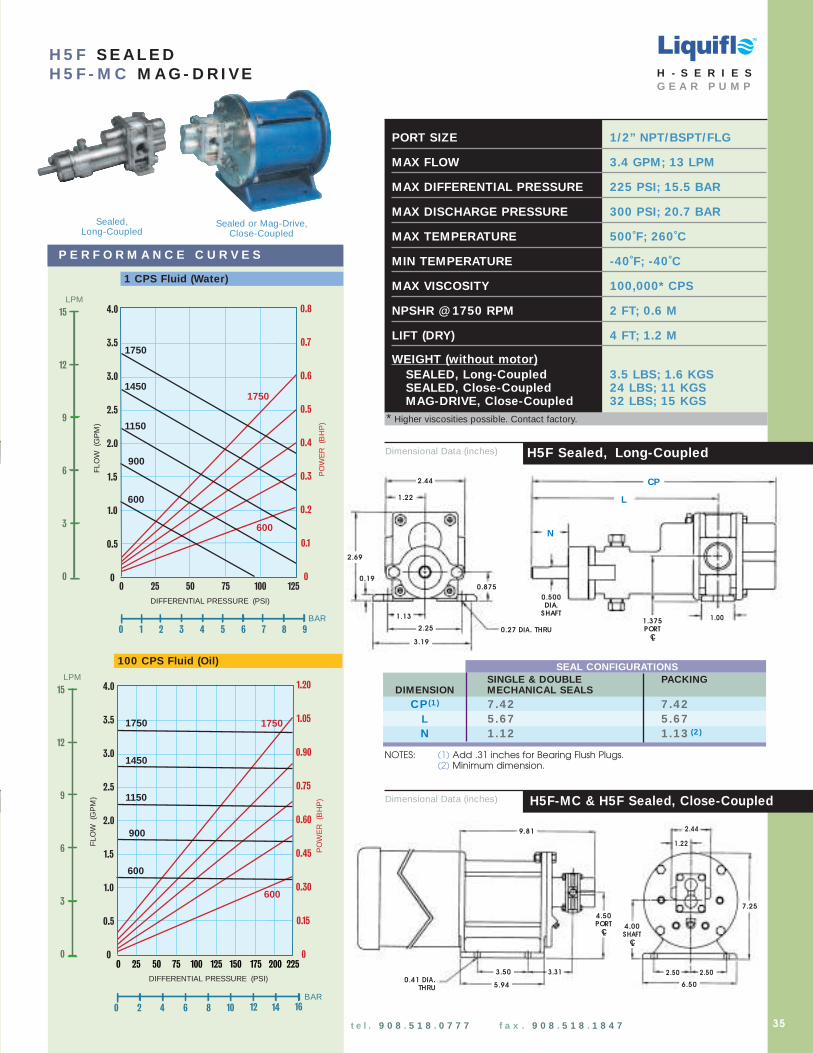
PORT SIZE 1/2” NPT/BSPT/FLG
MAX FLOW 3.4 GPM; 13 LPM
MAX DIFFERENTIAL PRESSURE 225 PSI; 15.5 BAR
MAX DISCHARGE PRESSURE 300 PSI; 20.7 BAR
MAX TEMPERATURE 500˚F; 260˚C
MIN TEMPERATURE -40˚F; -40˚C
MAX VISCOSITY 100,000* CPS
NPSHR @ 1750 RPM 2 FT; 0.6 M
LIFT (DRY) 4 FT; 1.2 M
WEIGHT (without motor)SEALED, Long-Coupled 3.5 LBS; 1.6 KGSSEALED, Close-Coupled 24 LBS; 11 KGSMAG-DRIVE, Close-Coupled 32 LBS; 15 KGS
DIFFERENTIAL PRESSURE (PSI)
4.0
3.5
3.0
2.5
2.0
1.5
1.0
0.5
0755025 1000
1750
1450
900
PO
WE
R(B
HP
)
FLO
W(G
PM
)
1750
600
600
1150
125
0.8
0.7
0.6
0.5
0.4
0.3
0.2
0.1
0
0 1 2 3 4 5 6 7 8 9
BAR
LPM
15
12
9
6
3
0
H 5 F S E A L E DH 5 F - M C M A G - D R I VE
H5F Sealed, Long-Coupled
H5F-MC & H5F Sealed, Close-Coupled
100 CPS Fluid (Oil)
P E R F O R M A N C E C U R V E S
1 CPS Fluid (Water)
Dimensional Data (inches)
Dimensional Data (inches)
TM
4.50 PORT
CL
9.81
7.25
5.94
3.50 3.31 2.50 2.50
6.50
2.44
1.22
0.41 DIA.THRU
4.00 SHAFT
CL
H - S E R I E SG E A R P U M P
* Higher viscosities possible. Contact factory.
1.22
2.25
1.13
3.19
2.69
0.19
0.27 DIA. THRU
L
CP
N
1.00
0.500DIA.
SHAFT
0.875
2.44
1.375PORT
CL
35t e l . 9 0 8 . 5 1 8 . 0 7 7 7 f a x . 9 0 8 . 5 1 8 . 1 8 4 7
NOTES: (1) Add .31 inches for Bearing Flush Plugs.(2) Minimum dimension.
SEAL CONFIGURATIONSSINGLE & DOUBLE P ACKING
DIMENSION MECHANICAL SEALSCP (1 ) 7 .42 7 .42
L 5 .67 5 .67N 1 .12 1 .13 (2 )
4.0
3.5
3.0
2.5
2.0
1.5
1.0
0.5
0
DIFFERENTIAL PRESSURE (PSI)
1750
1450
1150
900
PO
WE
R(B
HP
)
FLO
W(G
PM
)
600
100755025 2000 175150125 225
600
1.20
1.05
0.90
0.75
0.60
0.45
0.30
0.15
0
0 2 4 6 8
BAR10 12 14 16
1750
LPM
15
12
9
6
3
0
Sealed,Long-Coupled
Sealed or Mag-Drive,Close-Coupled

Dimensional Data (inches)
Dimensional Data (inches)
DIFFERENTIAL PRESSURE (PSI)
6
5
4
3
2
1
0755025 1000
1750
1450
900
PO
WE
R(B
HP
)
FLO
W(G
PM
)
1750
600
600
1150
1.2
1.0
0.8
0.6
0.4
0.2
0125
0 1 2 3 4 5 6 7 8 9
BAR
LPM22
20
18
16
14
12
10
8
6
4
2
0
6
5
4
3
2
1
0
DIFFERENTIAL PRESSURE (PSI)
1750
1450
1150
900
PO
WE
R(B
HP
)
FLO
W(G
PM
)
1750
600
100755025 2000 175150125 225
600
1.8
1.5
1.2
0.9
0.6
0.3
0
LPM22
20
18
16
14
12
10
8
6
4
2
0
0 2 4 6 8
BAR10 12 14 16
100 CPS Fluid (Oil)
1 CPS Fluid (Water)
P E R F O R M A N C E C U R V E S
H 7 N S E A L E DH 7 N - M C M A G - D R I VE
PORT SIZE 3/4” NPT/BSPT/FLG
MAX FLOW 5.4 GPM; 20 LPM
MAX DIFFERENTIAL PRESSURE 225 PSI; 15.5 BAR
MAX DISCHARGE PRESSURE 225 PSI; 15.5 BAR
MAX TEMPERATURE 500˚F; 260˚C
MIN TEMPERATURE -40˚F; -40˚C
MAX VISCOSITY 100,000* CPS
NPSHR @ 1750 RPM 5.2 FT; 1.6 M
LIFT (DRY) 6 FT; 1.8 M
WEIGHT (without motor)SEALED, Long-Coupled 6.5 LBS; 3 KGSSEALED, Close-Coupled 29 LBS; 13 KGSMAG-DRIVE, Close-Coupled 36 LBS; 16 KGS
H7N Sealed, Long-Coupled
H7N-MC & H7N Sealed, Close-Coupled
1.66
3.32
3.94
0.19
0.28 DIA. THRU
L
CP
N
0.875
0.625SHAFTDIA.
1.25
1.31
2.622.000PORT
CL
10.72
7.25
5.94
3.50 3.75 2.50
6.50
3.32
1.66
0.41 DIA.THRU
2.50
4.75 PORT
CL
4.00 SHAFT
CL
3.19
TM
H - S E R I E SG E A R P U M P
* Higher viscosities possible. Contact factory.
36 t e l . 9 0 8 . 5 1 8 . 0 7 7 7 f a x . 9 0 8 . 5 1 8 . 1 8 4 7
NOTES: (1) Add .31 inches for Bearing Flush Plugs.(2) Minimum dimension.
SEAL CONFIGURATIONSSINGLE & DOUBLE PACKING
DIMENSION MECHANICAL SEALSCP (1 ) 8 .20 8 .20
L 5 .98 5 .98N 1 .23 1 .25 (2 )
Sealed,Long-Coupled
Sealed or Mag-Drive,Close-Coupled
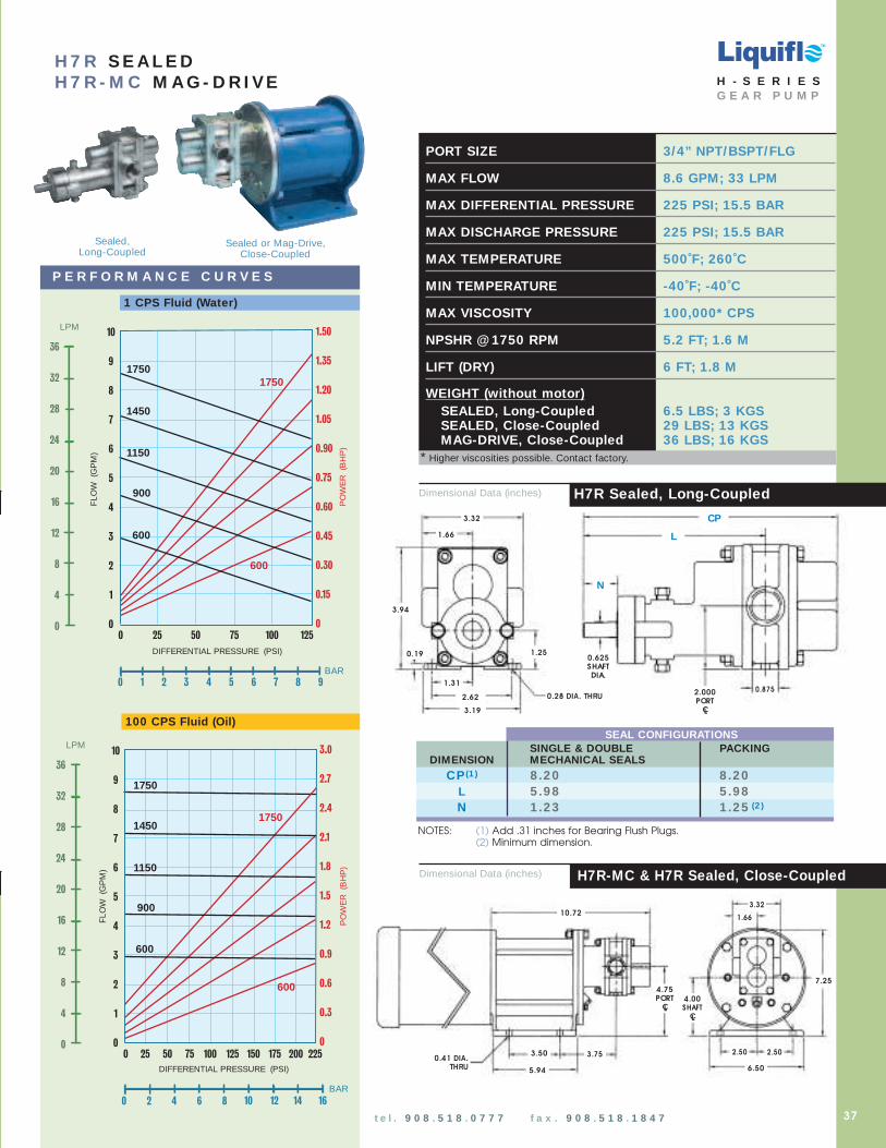
DIFFERENTIAL PRESSURE (PSI)
755025 1000
1750
1450
900
PO
WE
R(B
HP
)
FLO
W(G
PM
)
1750
600
600
1150
1.50
1.35
1.20
1.05
0.90
0.75
0.60
0.45
0.30
0.15
0
125
0 1 2 3 4 5 6 7 8 9
BAR
LPM
36
32
28
24
20
16
12
8
4
0
10
9
8
7
6
5
4
3
2
1
0
H 7 R S E A L E DH 7 R - M C M A G - D R I VE
10
9
8
7
6
5
4
3
2
1
0
DIFFERENTIAL PRESSURE (PSI)
1750
1450
1150
900
PO
WE
R(B
HP
)
FLO
W(G
PM
)
1750
600
100755025 2000 175150125 225
600
3.0
2.7
2.4
2.1
1.8
1.5
1.2
0.9
0.6
0.3
0
LPM
36
32
28
24
20
16
12
8
4
0
0 2 4 6 8
BAR10 12 14 16
H7R Sealed, Long-Coupled
H7R-MC & H7R Sealed, Close-Coupled
100 CPS Fluid (Oil)
P E R F O R M A N C E C U R V E S
1 CPS Fluid (Water)
PORT SIZE 3/4” NPT/BSPT/FLG
MAX FLOW 8.6 GPM; 33 LPM
MAX DIFFERENTIAL PRESSURE 225 PSI; 15.5 BAR
MAX DISCHARGE PRESSURE 225 PSI; 15.5 BAR
MAX TEMPERATURE 500˚F; 260˚C
MIN TEMPERATURE -40˚F; -40˚C
MAX VISCOSITY 100,000* CPS
NPSHR @ 1750 RPM 5.2 FT; 1.6 M
LIFT (DRY) 6 FT; 1.8 M
WEIGHT (without motor)SEALED, Long-Coupled 6.5 LBS; 3 KGSSEALED, Close-Coupled 29 LBS; 13 KGSMAG-DRIVE, Close-Coupled 36 LBS; 16 KGS
Dimensional Data (inches)
Dimensional Data (inches)
TM
1.66
3.32
3.94
0.19
0.28 DIA. THRU
L
CP
N
0.875
0.625SHAFTDIA.
1.25
1.31
2.622.000PORT
CL
10.72
7.25
5.94
3.50 3.75 2.50
6.50
3.32
1.66
0.41 DIA.THRU
2.50
4.75 PORT
CL
4.00 SHAFT
CL
3.19
H - S E R I E SG E A R P U M P
* Higher viscosities possible. Contact factory.
37t e l . 9 0 8 . 5 1 8 . 0 7 7 7 f a x . 9 0 8 . 5 1 8 . 1 8 4 7
NOTES: (1) Add .31 inches for Bearing Flush Plugs.(2) Minimum dimension.
SEAL CONFIGURATIONSSINGLE & DOUBLE P ACKING
DIMENSION MECHANICAL SEALSCP (1 ) 8 .20 8 .20
L 5 .98 5 .98N 1 .23 1 .25 (2 )
Sealed,Long-Coupled
Sealed or Mag-Drive,Close-Coupled
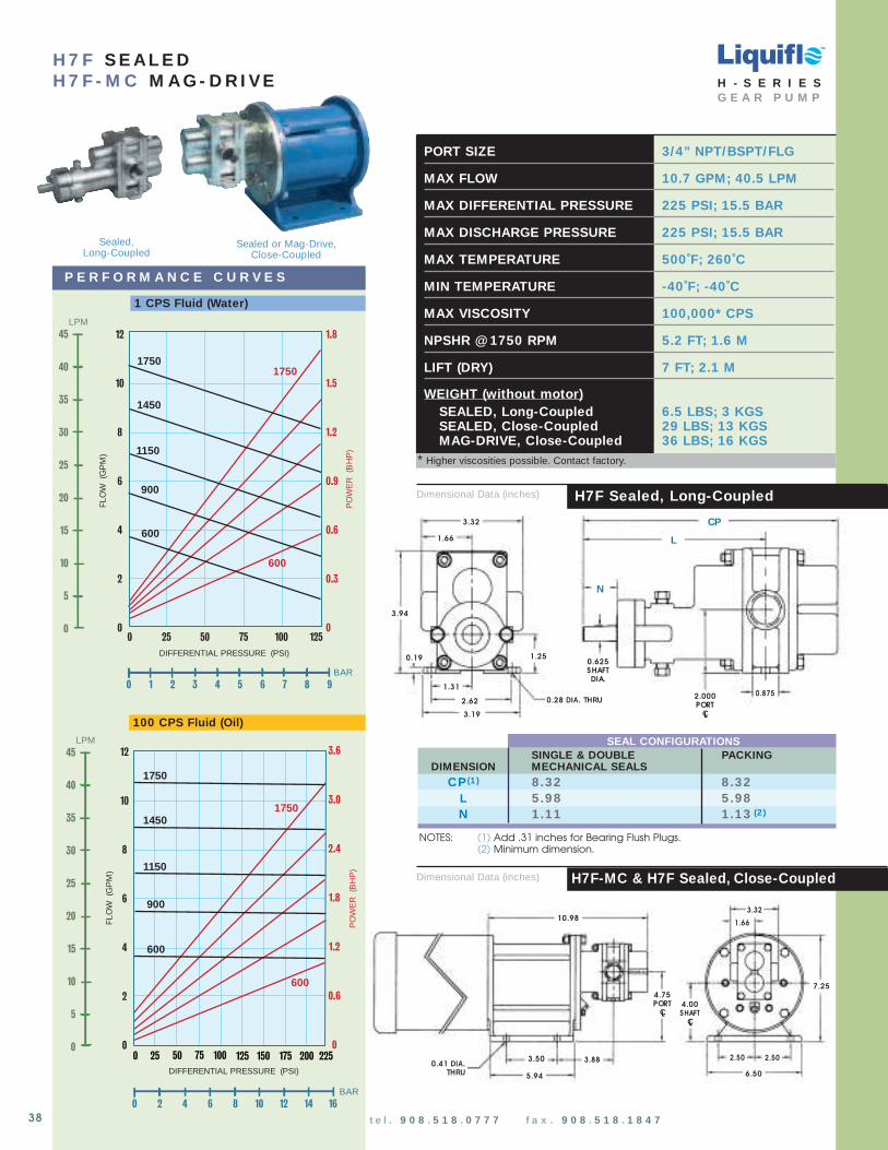
Dimensional Data (inches)
DIFFERENTIAL PRESSURE (PSI)
12
10
8
6
4
2
0755025 1000
1750
1450
900
PO
WE
R(B
HP
)
FLO
W(G
PM
)
1750
600
600
1150
1.8
1.5
1.2
0.9
0.6
0.3
0125
0 1 2 3 4 5 6 7 8 9
BAR
LPM45
40
35
30
25
20
15
10
5
0
12
10
8
6
4
2
0
DIFFERENTIAL PRESSURE (PSI)
1750
1450
1150
900
PO
WE
R(B
HP
)
FLO
W(G
PM
)
1750
600
100755025 2000 175150125 225
600
3.6
3.0
2.4
1.8
1.2
0.6
0
0 2 4 6 8
BAR10 12 14 16
LPM45
40
35
30
25
20
15
10
5
0
100 CPS Fluid (Oil)
1 CPS Fluid (Water)
P E R F O R M A N C E C U R V E S
H 7 F S E A L E DH 7 F - M C M A G - D R I VE
PORT SIZE 3/4” NPT/BSPT/FLG
MAX FLOW 10.7 GPM; 40.5 LPM
MAX DIFFERENTIAL PRESSURE 225 PSI; 15.5 BAR
MAX DISCHARGE PRESSURE 225 PSI; 15.5 BAR
MAX TEMPERATURE 500˚F; 260˚C
MIN TEMPERATURE -40˚F; -40˚C
MAX VISCOSITY 100,000* CPS
NPSHR @ 1750 RPM 5.2 FT; 1.6 M
LIFT (DRY) 7 FT; 2.1 M
WEIGHT (without motor)SEALED, Long-Coupled 6.5 LBS; 3 KGSSEALED, Close-Coupled 29 LBS; 13 KGSMAG-DRIVE, Close-Coupled 36 LBS; 16 KGS
H7F-MC & H7F Sealed, Close-CoupledDimensional Data (inches)
H7F Sealed, Long-Coupled
1.66
3.32
3.94
0.19
0.28 DIA. THRU
L
CP
N
0.875
0.625SHAFTDIA.
1.25
1.31
2.622.000PORT
CL
10.98
7.25
5.94
3.50 3.88 2.50
6.50
3.32
1.66
0.41 DIA.THRU
2.50
4.75PORT
CL
4.00 SHAFT
CL
3.19
TM
H - S E R I E SG E A R P U M P
* Higher viscosities possible. Contact factory.
38 t e l . 9 0 8 . 5 1 8 . 0 7 7 7 f a x . 9 0 8 . 5 1 8 . 1 8 4 7
NOTES: (1) Add .31 inches for Bearing Flush Plugs.(2) Minimum dimension.
SEAL CONFIGURATIONSSINGLE & DOUBLE P ACKING
DIMENSION MECHANICAL SEALSCP (1 ) 8 .32 8 .32
L 5 .98 5 .98N 1 .11 1 .13 (2 )
Sealed,Long-Coupled
Sealed or Mag-Drive,Close-Coupled
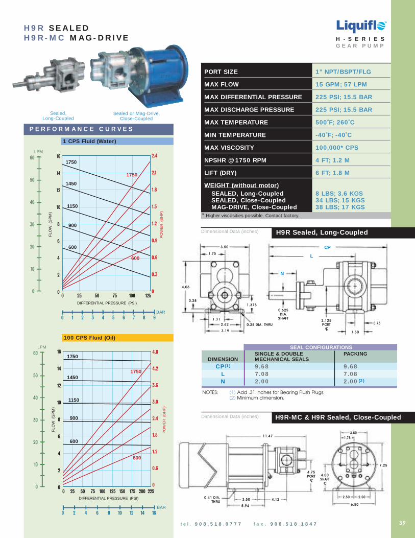
PORT SIZE 1” NPT/BSPT/FLG
MAX FLOW 15 GPM; 57 LPM
MAX DIFFERENTIAL PRESSURE 225 PSI; 15.5 BAR
MAX DISCHARGE PRESSURE 225 PSI; 15.5 BAR
MAX TEMPERATURE 500˚F; 260˚C
MIN TEMPERATURE -40˚F; -40˚C
MAX VISCOSITY 100,000* CPS
NPSHR @ 1750 RPM 4 FT; 1.2 M
LIFT (DRY) 6 FT; 1.8 M
WEIGHT (without motor)SEALED, Long-Coupled 8 LBS; 3.6 KGSSEALED, Close-Coupled 34 LBS; 15 KGSMAG-DRIVE, Close-Coupled 38 LBS; 17 KGS
DIFFERENTIAL PRESSURE (PSI)
755025 1000
1750
1450
900
PO
WE
R (
BH
P)
FLO
W (
GP
M)
1750
600
600
1150
2.4
2.1
1.8
1.5
1.2
0.9
0.6
0.3
0125
0 1 2 3 4 5 6 7 8 9
BAR
16
14
12
10
8
6
4
2
0
LPM
60
50
40
30
20
10
0
H 9 R S E A L E DH 9 R - M C M A G - D R I VE
DIFFERENTIAL PRESSURE (PSI)
1750
1450
1150
900
PO
WE
R(B
HP
)
FLO
W(G
PM
)
1750
600
100755025 2000 175150125 225
600
4.8
4.2
3.6
3.0
2.4
1.8
1.2
0.6
0
0 2 4 6 8
BAR10 12 14 16
16
14
12
10
8
6
4
2
0
LPM
60
50
40
30
20
10
0
H9R Sealed, Long-Coupled
H9R-MC & H9R Sealed, Close-Coupled
100 CPS Fluid (Oil)
P E R F O R M A N C E C U R V E S
1 CPS Fluid (Water)
Dimensional Data (inches)
Dimensional Data (inches)
TM
H - S E R I E SG E A R P U M P
* Higher viscosities possible. Contact factory.
39t e l . 9 0 8 . 5 1 8 . 0 7 7 7 f a x . 9 0 8 . 5 1 8 . 1 8 4 7
11.47
7.25
5.94
3.50 4.122.50
6.50
0.41 DIA.THRU
2.50
1.75
3.50
1.31
2.62
3.19
4.06
0.28
0.28 DIA. THRU
L
CP
1.50
0.625DIA.
SHAFT
0.75
N
1.75
1.375
2.125PORT
CL
4.00 SHAFT
CL
4.75 PORT
CL
3.50
NOTES: (1) Add .31 inches for Bearing Flush Plugs.(2) Minimum dimension.
SEAL CONFIGURATIONSSINGLE & DOUBLE PACKING
DIMENSION MECHANICAL SEALSCP (1 ) 9 .68 9 .68
L 7 .08 7 .08N 2 .00 2 .00 (2 )
Sealed,Long-Coupled
Sealed or Mag-Drive,Close-Coupled

Dimensional Data (inches)
DIFFERENTIAL PRESSURE (PSI)
755025 1000
1750
1450
900
PO
WE
R(B
HP
)
FLO
W(G
PM
)
1750
600
600
1150
3.5
2.8
2.1
1.4
0.7
0
125
0 1 2 3 4 5 6 7 8 9
BAR
LPM
90
80
70
60
50
40
30
20
10
0
25
20
15
10
5
0
DIFFERENTIAL PRESSURE (PSI)
1750
1450
1150
900
PO
WE
R(B
HP
)
FLO
W(G
PM
)
1750
600
100755025 2000 175150125 225
600
7.5
6.0
4.5
3.0
1.5
0
0 2 4 6 8
BAR10 12 14 16
25
20
15
10
5
0
LPM
90
80
70
60
50
40
30
20
10
0
100 CPS Fluid (Oil)
1 CPS Fluid (Water)
P E R F O R M A N C E C U R V E S
H 9 F S E A L E DH 9 F - M C M A G - D R I VE
PORT SIZE 11/ 4” NPT/BSPT/FLG
MAX FLOW 21.5 GPM; 81.4 LPM
MAX DIFFERENTIAL PRESSURE 225 PSI; 15.5 BAR
MAX DISCHARGE PRESSURE 225 PSI; 15.5 BAR
MAX TEMPERATURE 500˚F; 260˚C
MIN TEMPERATURE -40˚F; -40˚C
MAX VISCOSITY 100,000* CPS
NPSHR @ 1750 RPM 3 FT; 0.9 M
LIFT (DRY) 14 FT; 4.2 M
WEIGHT (without motor)SEALED, Long-Coupled 10 LBS; 4.5 KGSSEALED, Close-Coupled 36 LBS; 16 KGSMAG-DRIVE, Close-Coupled 40 LBS; 18 KGS
H9F-MC & H9F Sealed, Close-CoupledDimensional Data (inches)
H9F Sealed, Long-Coupled
TM
H - S E R I E SG E A R P U M P
* Higher viscosities possible. Contact factory.
40 t e l . 9 0 8 . 5 1 8 . 0 7 7 7 f a x . 9 0 8 . 5 1 8 . 1 8 4 7
12.22
7.25
5.94
3.50 4.502.50
6.50
0.41 DIA.THRU
2.50
2.00
4.00 SHAFT
CL
4.75 PORT
CL
2.00
4.00
1.31
2.62
3.19
4.06
0.28
0.28 DIA. THRU
N
CP
2.23
0.625DIA.
SHAFT
1.25
.63
1.375
2.125PORT
CL
L
4.00
NOTES: (1) Add .31 inches for Bearing Flush Plugs.(2) Minimum dimension.
SEAL CONFIGURATIONSSINGLE & DOUBLE P ACKING
DIMENSION MECHANICAL SEALSCP (1 ) 10 .44 10 .44
L 7 .47 7 .47N 2 .00 2 .00 (2 )
Sealed,Long-Coupled
Sealed or Mag-Drive,Close-Coupled

0.50
16.30
9.38
12.36
7.25
10.00
0.34 DIA. THRU
DRAIN PLUG(MC ONLY)
2.38
0.75
3.81
9.50
5.00
5.00
FLUSH PLUGS
3.63
DIFFERENTIAL PRESSURE (PSI)
25
20
15
10
5
0755025 1000
1150
600
PO
WE
R(B
HP
)
FLO
W(G
PM
)
1150
300
300
900
125
0 1 2 3 4 5 6 7 8 9
BAR
LPM
90
80
70
60
50
40
30
20
10
0
5
4
3
2
1
0
H 1 2 R S E A L E DH 1 2 R - M C M A G - D R I VE
25
20
15
10
5
0
DIFFERENTIAL PRESSURE (PSI)
1150
900
600
PO
WE
R(B
HP
)
FLO
W(G
PM
)
1150
300
100755025 2000 175150125 225
300
7.5
6.0
4.5
3.0
1.5
0
LPM
90
80
70
60
50
40
30
20
10
0
0 2 4 6 8
BAR10 12 14 16
100 CPS Fluid (Oil)
P E R F O R M A N C E C U R V E S
1 CPS Fluid (Water)
TM
H12R-MC & H12R Sealed, Close-CoupledDimensional Data (inches)
CPL
1.125DIA.
SHAFT
7.50
0.34 DIA. THRU
5.00
0.50
1.503.63
5.00SHAFT
CL
2.38
0.753.63
10.00
N
3.81PORT
CL
Dimensional Data (inches) H12R Sealed, Long-Coupled
H - S E R I E SG E A R P U M P
* Higher viscosities possible. Contact factory.
PORT SIZE 11/ 2” FLG or 1 1/ 4” NPT/BSPT
MAX FLOW 22 GPM; 83 LPM
MAX DIFFERENTIAL PRESSURE 225 PSI; 15.5 BAR
MAX DISCHARGE PRESSURE 270 PSI; 18.6 BAR
MAX TEMPERATURE 500˚F; 260˚C
MIN TEMPERATURE -40˚F; -40˚ C
MAX VISCOSITY 100,000* CPS
NPSHR @ 1150 RPM 5 FT; 1.5 M
LIFT (DRY) 15 FT; 4.5 M
WEIGHT (without motor)SEALED, Long-Coupled 52 LBS; 24 KGSSEALED, Close-Coupled 77 LBS; 35 KGSMAG-DRIVE, Close-Coupled 95 LBS; 43 KGS
41
Sealed,Long-Coupled
Sealed or Mag-Drive,Close-Coupled
t e l . 9 0 8 . 5 1 8 . 0 7 7 7 f a x . 9 0 8 . 5 1 8 . 1 8 4 7
NOTES: (1) Add .31 inches for Bearing Flush Plugs. (2) Minimum dimension.
SEAL CONFIGURATIONSDIMENSION SINGLE & DOUBLE PACKING
MECHANICAL SEALS
CP (1 ) 13 .69 13 .69L 9 .75 9 .75N 2 .56 2 .28 (2 )

* Higher viscosities possible. Contact factory.
PORT SIZE 11/ 2” FLG or 1 1/ 4” NPT/BSPT
MAX FLOW 29 GPM; 110 LPM
MAX DIFFERENTIAL PRESSURE 225 PSI; 15.5 BAR
MAX DISCHARGE PRESSURE 270 PSI; 18.6 BAR
MAX TEMPERATURE 500˚F; 260˚C
MIN TEMPERATURE -40˚F; -40˚ C
MAX VISCOSITY 100,000* CPS
NPSHR @ 1150 RPM 5 FT; 1.5 M
LIFT (DRY) 17 FT; 5.2 M
WEIGHT (without motor)SEALED, Long-Coupled 52 LBS; 24 KGSSEALED, Close-Coupled 77 LBS; 35 KGSMAG-DRIVE, Close-Coupled 95 LBS; 43 KGS
100 CPS Fluid (Oil)
1 CPS Fluid (Water)
P E R F O R M A N C E C U R V E S
H 1 2 F S E A L E DH 1 2 F - M C M A G - D R I VE
42t e l . 9 0 8 . 5 1 8 . 0 7 7 7 f a x . 9 0 8 . 5 1 8 . 1 8 4 7
Sealed,Long-Coupled
Sealed or Mag-Drive,Close-Coupled
DIFFERENTIAL PRESSURE (PSI)
35
30
25
20
15
10
5
0
755025 1000
1150
600
PO
WE
R(B
HP
)
FLO
W(G
PM
) 1150
300
300
900
0 1 2 3 4 5 6 7 8 9
BAR
125
7
6
5
4
3
2
1
0
LPM
120
100
80
60
40
20
0
DIFFERENTIAL PRESSURE (PSI)
1150
900
600
PO
WE
R(B
HP
)
FLO
W(G
PM
)
1150
300
100755025 2000 175150125 225
300
10.5
9.0
7.5
6.0
4.5
3.0
1.5
0
35
30
25
20
15
10
5
0
0 2 4 6 8
BAR10 12 14 16
LPM
120
100
80
60
40
20
0
0.50
16.30
9.38
12.36
7.25
10.00
0.34 DIA. THRU
DRAIN PLUG(MC ONLY)
2.38
0.75
3.81
9.50
5.00
5.00
FLUSH PLUGS
3.63
TM
H12F-MC & H12F Sealed, Close-CoupledDimensional Data (inches)
CPL
1.125DIA.
SHAFT
7.50
0.34 DIA. THRU
5.00
0.50
1.503.63
5.00SHAFT
CL
2.38
0.753.63
10.00
N
3.81PORT
CL
Dimensional Data (inches) H12F Sealed, Long-Coupled
H - S E R I E SG E A R P U M P
NOTES: (1) Add .31 inches for Bearing Flush Plugs. (2) Minimum dimension.
SEAL CONFIGURATIONSDIMENSION SINGLE & DOUBLE PACKING
MECHANICAL SEALS
CP (1 ) 13 .69 13 .69L 9 .75 9 .75N 2 .56 2 .28 (2 )

t e l . 9 0 8 . 5 1 8 . 0 7 7 7 f a x . 9 0 8 . 5 1 8 . 1 8 4 7 w w w . l i q u i f l o . c o m
3 - SE RI E S L I QU I FLO E X T E RN AL GE AR P U M P S
L I Q U I F L O C H E M I C A L P R O C E S S I N G P U M P S
TM
43
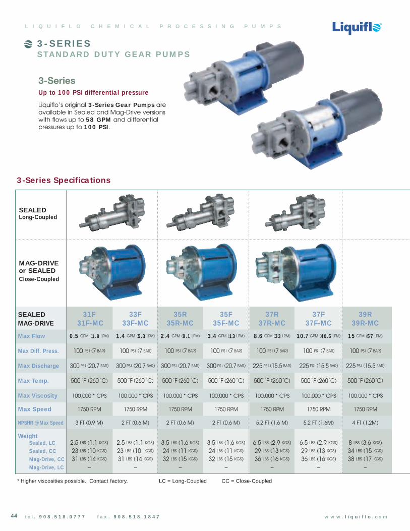
t e l . 9 0 8 . 5 1 8 . 0 7 7 7 f a x . 9 0 8 . 5 1 8 . 1 8 4 7 w w w . l i q u i f l o . c o m
3 - SE RI E SSTAN D ARD D U T Y GE AR P U M P S
SEALED 31F 33F 35R 35F 37R 37F 39RMAG-DRIVE 31F-MC 33F-MC 35R-MC 35F-MC 37R-MC 37F-MC 39R-MC
Max Flow 0.5 GPM (1 .9 LPM) 1 .4 GPM (5 .3 LPM) 2 .4 GPM (9 .1 LPM) 3 .4 GPM (13 LPM) 8 .6 GPM (33 LPM) 10 .7 GPM (40 .5 LPM) 15 GPM (57 LPM)
Max Diff. Press. 100 PS I (7 BAR) 100 PS I (7 BAR) 100 PS I (7 BAR) 100 PS I (7 BAR) 100 PS I (7 BAR) 100 PS I (7 BAR) 100 PS I (7 BAR)
Max Discharge 300 PS I (20.7 BAR) 300 PS I (20.7 BAR) 300 PS I (20.7 BAR) 300 PS I (20.7 BAR) 225 PS I (15.5 BAR) 225 PS I (15.5 BAR) 225 PS I (15.5 BAR)
Max Temp. 500 ˚F (260 ˚C) 500 ˚F (260 ˚C) 500 ˚F (260 ˚C) 500 ˚F (260 ˚C) 500 ˚F (260˚C) 500 ˚F (260˚C) 500 ˚F (260˚C)
Max Viscosity 100,000 * CPS 100,000 * CPS 100,000 * CPS 100,000 * CPS 100,000 * CPS 100,000 * CPS 100,000 * CPS
Max Speed 1750 RPM 1750 RPM 1750 RPM 1750 RPM 1750 RPM 1750 RPM 1750 RPM
NPSHR @ Max Speed 3 FT (0.9 M) 2 FT (0.6 M) 2 FT (0.6 M) 2 FT (0.6 M) 5.2 FT (1.6 M) 5.2 FT (1.6M) 4 FT (1.2M)
WeightSealed, LC 2.5 LBS (1.1 KGS) 2.5 LBS (1.1 KGS) 3.5 LBS (1.6 KGS) 3.5 LBS (1.6 KGS) 6.5 LBS (2.9 KGS) 6.5 LBS (2.9 KGS) 8 LBS (3.6 KGS)
Sealed, CC 23 LBS (10 KGS) 23 LBS (10 KGS) 24 LBS (11 KGS) 24 LBS (11 KGS) 29 LBS (13 KGS) 29 LBS (13 KGS) 34 LBS (15 KGS)
Mag-Drive, CC 31 LBS (14 KGS) 31 LBS (14 KGS) 32 LBS (15 KGS) 32 LBS (15 KGS) 36 LBS (16 KGS) 36 LBS (16 KGS) 38 LBS (17 KGS)
Mag-Drive, LC – – – – – – –
3-Series
Up to 100 PSI differentia l pressure
Liquiflo’s original 3-Series Gear Pumps are available in Sealed and Mag-Drive versions with flows up to 58 GPM and differentialpressures up to 100 PSI.
44
3-Series Specifica tions
* Higher viscosities possible. Contact factory. LC = Long-Coupled CC = Close-Coupled
L I Q U I F L O C H E M I C A L P R O C E S S I N G P U M P S
SEALEDLong-Coupled
MAG-DRIVEor SEALEDClose-Coupled
TM
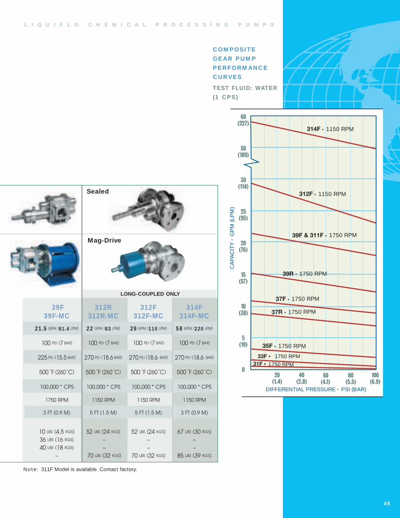
C OM P OSI T E
GE AR P U M P
P E RFORM AN C E
C U RVE S
TEST FLUID: WATER
(1 C P S)
60
50
30
25
20
15
10
5
080(5.5)
60(4.1)
40(2.8)
20(1.4)
DIFFERENTIAL PRESSURE • PSI (BAR)
CA
PA
CIT
Y•
GP
M(L
PM
)
37F • 1750 RPM
31F • 1750 RPM
39F & 311F • 1750 RPM
312F • 1150 RPM
314F • 1150 RPM
100(6.9)
35F • 1750 RPM
(227)
(189)
(114)
(95)
(76)
(57)
(38)
(19)
37R • 1750 RPM
33F • 1750 RPM
39R • 1750 RPM
L I Q U I F L O C H E M I C A L P R O C E S S I N G P U M P S
Not e: 311F Model is available. Contact factory.
45
39F 312R 312F 314F39F-MC 312R-MC 312F-MC 314F-MC
21 .5 GPM (81 .4 LPM) 22 GPM (83 LPM) 29 GPM (110 LPM) 58 GPM (220 LPM)
100 PS I (7 BAR) 100 PS I (7 BAR) 100 PS I (7 BAR) 100 PS I (7 BAR)
225 PS I (15.5 BAR) 270 PS I (18.6 BAR) 270 PS I (18.6 BAR) 270 PS I (18.6 BAR)
500 ˚F (260 ˚C) 500 ˚F (260 ˚C) 500 ˚F (260 ˚C) 500 ˚F (260 ˚C)
100,000 * CPS 100,000 * CPS 100,000 * CPS 100,000 * CPS
1750 RPM 1150 RPM 1150 RPM 1150 RPM
3 FT (0.9 M) 5 FT (1.5 M) 5 FT (1.5 M) 3 FT (0.9 M)
10 LBS (4.5 KGS) 52 LBS (24 KGS) 52 LBS (24 KGS) 67 LBS (30 KGS)
36 LBS (16 KGS) – – –
40 LBS (18 KGS) – – –
– 70 LBS (32 KGS) 70 LBS (32 KGS) 85 LBS (39 KGS)
LONG-COUPLED ONLY
Sealed
Mag-Drive
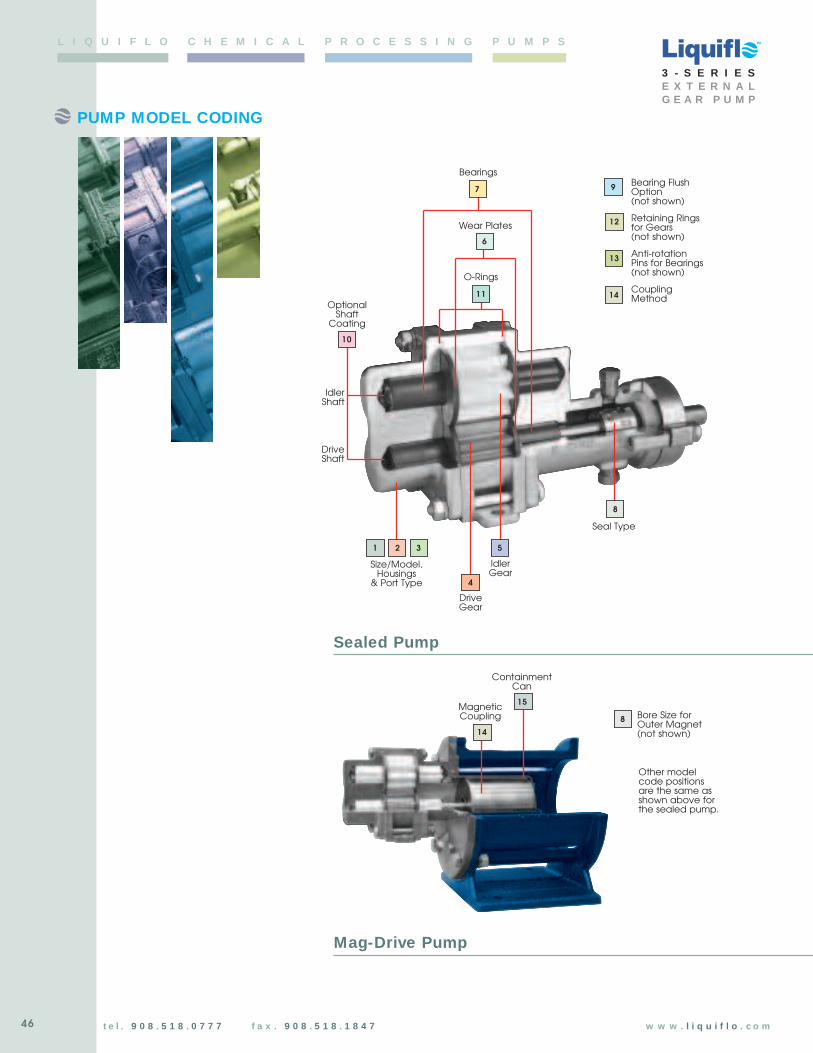
46
PUMP MODEL CODING
t e l . 9 0 8 . 5 1 8 . 0 7 7 7 f a x . 9 0 8 . 5 1 8 . 1 8 4 7 w w w . l i q u i f l o . c o m
L I Q U I F L O C H E M I C A L P R O C E S S I N G P U M P S
3 - S E R I E SE X T E R N A LG E A R P U M P
Bearings
Wear Plates
IdlerGear
Seal Type
Size/Model,Housings
& Port Type
MagneticCoupling
DriveGear
DriveShaft
IdlerShaft
OptionalShaft
Coating
1 2 3
4
5
6
7
8
10
11
12
13
O-Rings
14
8 Bore Size forOuter Magnet(not shown)
Bearing FlushOption(not shown)
Retaining Ringsfor Gears(not shown)
Anti-rotationPins for Bearings(not shown)
CouplingMethod
15
ContainmentCan
Other modelcode positions are the same asshown above forthe sealed pump.
9
Sealed Pump
Mag-Drive Pump
14
TM

47
PUMP MODEL CODING Liquiflo 3-Series Gear PumpsSelection & Availability
t e l . 9 0 8 . 5 1 8 . 0 7 7 7 f a x . 9 0 8 . 5 1 8 . 1 8 4 7
35 F S 6 P E E U 0 0 0 0 0 9
Pump Model 35F 35F Pump
Housing Mat’l S 316 SS NPT
Drive Gear Mat’l 6 316 SS
Idler Gear Mat’l P PEEK
Wear Plate Mat’l E Carbon 60
Bearing Mat’l E Carbon 60
Seal Type U Single-Int, Carbon-SiC
Bearing Flush 0 None
Shaft Coating 0 None
O-Rings 0 Teflon
Retaining Ring 0 316 SS
Bearing Pins 0 Teflon
Coupling Method 9 Long-Coupled
N/A
1&2 3 4 5 6 7 8 9 10 11 12 13 14 15
1 & 2
3
4
5
6
7
8
9
10
11
12
13
14
15
Liquiflo’s Model Codedescribes both the pump’s size and materials selected. This model code is required forthe future identification of yourpump when reordering either a pump or replacement parts. Model code is permanently stamped into pump housing.
n Available
U Not Available
CF Contact Factory
Note: Delrin Gears (Code = 5) are no longer available in new pumps but are available for repair and replacement only.
Flanges available:
ANSI, DIN, JIS,or slip joint flanges conforming to the dimensionsof the standard.
CONNECTION SIZES
31/33 35 37 39R 39F 312 314
NPT/BSPT 1/4 1/2 3/4 1 11/4 11/4 –
ANSI 150# RF 1/2 1/2 3/4 1 11/4 11/2 21/2
DIN PN16 10 15 20 25 32 40 65
JIS 10K 10 15 20 25 32 40 65
Note: 311F pumps available with same features as 39F
EXAM PLE:35FS6PEEU000009, designates a Model35F Pump with Single Mechanical Seal.
Pos. Description Selection
31 33 35 37 39 312 314
F = Full Capacity n n n n n n n
R = Reduced Capacity U U n n n n U
S = 316 SS NPT n n n n n n UL = 316 SS Flanged n n n n n n n
X = 316 SS BSPT n n n n n n UH = Alloy-C NPT n n n n n n UC = Alloy-C Flanged n n n n n n n
Y = Alloy-C BSPT n n n n n n UD = Alloy-20 NPT n n n n n n UW = Alloy-20 BSPT n n n n n n U
1 = Alloy-C n n n n n n n
3 = Teflon CF n n n n n n
6 = 316 SS n n n n n n n
P = PEEK n n n n n n n
1 = Alloy-C n n n n n n n
2 = Carbon U n n n n U U3 = Teflon CF n n n n n n
6 = 316 SS n n n n n n n
8 = Ryton n n n n n n n
P = PEEK n n n n n n n
3 = Teflon n n n n n n n
4 = Ceramic (SiC) n n n n n n n
E = Carbon 60 n n n n n n n
P = PEEK n n n n n n n
3 = Teflon n n n n n n n
B = Silicon Carbide n n n n n n n
E = Carbon 60 n n n n n n n
P = PEEK n n n n n n n
0 = 0.625” (NEMA 56C/56HC) n n n n n U U1 = 0.875” (NEMA 143/145TC) n n n n n n n
2 = 14 mm (IEC 71 - B5) n n n n n U U3 = 19 mm (IEC 80 - B5) n n n n n U U4 = 24 mm (IEC 90 - B5) n n n n n U U5 = 1.125” (NEMA 182/184TC) n n n n n U U
U = Single-Int Carbon - SiC n n n n n n n
S = Single-Int Teflon - SiC n n n n n n n
W = Single-Ext Carbon - SiC n n n n U U UX = Single-Ext Teflon - SiC n n n n U U UF = Double Carbon - SiC n n n n n n n
H = Double Teflon - SiC n n n n n n n
J = U-Cup Viton n n n n U U UL = Packing Teflon n n n n n n n
R = Packing Graphoil n n n n n n n
0 = Standard Housings n n n n n U U1 = External Bearing Flush n n n n n n n
2 = Internal Bearing Flush n n n n n n n
0 = Material same as housing (uncoated) n n n n n n n
1 = Ceramic n n n n n n n
2 = Tungsten Carbide n n n n n n n
0 = Teflon U n n n n n n
6 = 316 SS / PTFE encapsulated n n n n n n n
B = Buna-N n n n n n n n
E = EPDM n n n n n n n
V = Viton n n n n n n n
K = Kalrez n n n n n n n
0 = Material same as housing n n n n n n n
0 = Teflon n n n n n U U1 = Alloy-C n n n n n n n
6 = 316 SS n n n n n n n
0 = Close-Coupled (NEMA 56C/56HC) n n n n n U U1 = Close-Coupled (NEMA 143/145TC) n n n n n n n
2 = Close-Coupled (IEC 71 - B5) n n n n n U U3 = Close-Coupled (IEC 80 - B5) n n n n n U U4 = Close-Coupled (IEC 90 - B5) n n n n n U U5 = Close-Coupled (NEMA 182/184TC) n n n n n U U9 = Long-Coupled n n n n n U U
U = 75 in-lbs n n n n n U UB = 120 in-lbs n n n n n U UV = 200 in-lbs U U n n n U UK = 325 in-lbs U U U U U n n
J = 650 in-lbs U U U U U n n
S = Single Wall Can n n n n n n n
D = Dual Kan n n n n n n n
- 8 = Temperature Trim n n n n n n n
- 9D = Viscosity Trim (double clearance) n n n n n n n
- 9T = Viscosity Trim (triple clearance) n n n n n n n
n Long-coupled pumps (MC: 0.875” dia. shaft; Sealed: 1.000” dia. shaft)
2PositionModel
3PositionBasic Material &
Port Type
4PositionDrive Gear
5PositionIdler Gear
6PositionWear Plates
7PositionBearings
8PositionOuter Magnet
Bore(Mag-Drive)
9PositionBearing Flush
Option
10PositionShaft Coating
11PositionO-Rings
12PositionRetaining Rings
13PositionBearing Pins
14PositionMagnetic Coupling
(Mag Drive)
15PositionContainment Can
Pump Model1PositionModel
Sample Model No.
Position No.
35 F S 6 P E E U 0 0 0 0 01 2 3 4 5 6 7 8 9 10 11 12 13 14 15
8PositionSeal Type
(Sealed)
SuffixTrim Options
14PositionCoupling
Method(Sealed)
9
TM

TM
DIFFERENTIAL PRESSURE (PSI)
0.6
0.5
0.4
0.3
0.2
0.1
0806040200
1750
1450
FLO
W(G
PM
)
600
1750 LPM
2.0
1.8
1.6
1.4
1.2
1.0
0.8
0.6
0.4
0.2
0
0 2 4 6 8
BAR
100
0.12
0.10
0.08
0.06
0.04
0.02
0
PO
WE
R(B
HP
)
900
600
1150
3 1 F S E A L E D3 1 F - M C M A G - D R I VE
NOTES: (1) Add .31 inches for Bearing Flush Plugs.(2) Minimum dimension.
31F Sealed, Long-Coupled
31F-MC & 31F Sealed, Close-Coupled
100 CPS Fluid (Oil)
P E R F O R M A N C E C U R V E S
1 CPS Fluid (Water)
3 - S E R I E SG E A R P U M P
PORT SIZE 1/4” NPT/BSPT or 1/2” FLG
MAX FLOW 0.5 GPM; 1.9 LPM
MAX DIFFERENTIAL PRESSURE 100 PSI; 7 BAR
MAX DISCHARGE PRESSURE 300 PSI; 20.7 BAR
MAX TEMPERATURE 500˚F; 260˚C
MIN TEMPERATURE -40˚F; -40˚C
MAX VISCOSITY 100,000* CPS
NPSHR @ 1750 RPM 3 FT; 0.9 M
LIFT (DRY) 0.5 FT; 0.15 M
WEIGHT (without motor)SEALED, Long-Coupled 2.5 LBS; 1.1 KGSSEALED, Close-Coupled 23 LBS; 10 KGSMAG-DRIVE, Close-Coupled 31 LBS; 14 KGS
Dimensional Data (inches)
Dimensional Data (inches)
1.34
2.75
1.38
3.19
2.69
0.19
0.27 DIA. THRU
L
CP
N
0.63
0.375DIA.
SHAFT
SEAL CONFIGURATIONSSINGLE & DOUBLE EXTERNAL PACKING LIP
DIMENSION MECHANICAL MECHANICAL SEALSEALS SEAL
CP (1 ) 6 .94 7 .66 6 .94 6 .94L 5 .44 6 .16 5 .44 5 .44N 1 .12 1 .84 1 .19 (2 ) 1 .57
2.68
.875
4.50 PORT
CL
9.31
7.25
5.94
3.50 3.06 2.50 2.50
6.50
2.68
1.34
0.41 DIA.THRU
4.00 SHAFT
CL
1.375PORT
CL
* Higher viscosities possible. Contact factory.
48
DIFFERENTIAL PRESSURE (PSI)
0.6
0.5
0.4
0.3
0.2
0.1
0806040200
1750
1450
FLO
W(G
PM
)
600
1750 LPM
2.0
1.8
1.6
1.4
1.2
1.0
0.8
0.6
0.4
0.2
0
0 2 4 6 8
BAR
100
0.12
0.10
0.08
0.06
0.04
0.02
0
PO
WE
R(B
HP
)
600
900
1150
Sealed,Long-Coupled
Sealed or Mag-Drive,Close-Coupled

TM
PORT SIZE 1/4” NPT/BSPT or 1/2” FLG
MAX FLOW 1.4 GPM; 5.3 LPM
MAX DIFFERENTIAL PRESSURE 100 PSI; 7 BAR
MAX DISCHARGE PRESSURE 300 PSI; 20.7 BAR
MAX TEMPERATURE 500˚F; 260˚C
MIN TEMPERATURE -40˚F; -40˚C
MAX VISCOSITY 100,000* CPS
NPSHR @ 1750 RPM 2 FT; 0.6 M
LIFT (DRY) 1.5 FT; 0.45 M
WEIGHT (without motor)
SEALED, Long-Coupled 2.5 LBS; 1.1 KGSSEALED, Close-Coupled 23 LBS; 10 KGSMAG-DRIVE, Close-Coupled 31 LBS; 14 KGS
4.50 PORT
CL
9.31
7.25
5.94
3.50 3.06 2.50 2.50
6.50
2.68
1.34
0.41 DIA.THRU
0 2 4 6 8
BAR
DIFFERENTIAL PRESSURE (PSI)
1.6
1.4
1.2
1.0
0.8
0.6
0.4
0.2
0
80604020 1000
1750
1450
1150
900
PO
WE
R(B
HP
)
FLO
W(G
PM
)
600
1750
0.4
0.3
0.2
0.1
0
600
LPM
6
5
4
3
2
1
0
0 2 4 6 8
BAR
DIFFERENTIAL PRESSURE (PSI)
80604020 1000
1750
1450
1150
900
PO
WE
R(B
HP
)
FLO
W(G
PM
)
600
1750
600
1.6
1.4
1.2
1.0
0.8
0.6
0.4
0.2
0
LPM
6
5
4
3
2
1
0
0.4
0.3
0.2
0.1
0
100 CPS Fluid (Oil)
1 CPS Fluid (Water)
P E R F O R M A N C E C U R V E S
3 3 F S E A L E D3 3 F - M C M A G - D R I VE
33F Sealed, Long-Coupled
33F-MC & 33F Sealed, Close-Coupled
Dimensional Data (inches)
Dimensional Data (inches)
4.00 SHAFT
CL
1.34
2.75
1.38
3.19
2.69
0.19
0.27 DIA. THRU
L
CP
N
0.63
0.375DIA.
SHAFT
2.68
.875
1.375PORT
CL
3 - S E R I E SG E A R P U M P
* Higher viscosities possible. Contact factory.
t e l . 9 0 8 . 5 1 8 . 0 7 7 7 f a x . 9 0 8 . 5 1 8 . 1 8 4 749
NOTES: (1) Add .31 inches for Bearing Flush Plugs.(2) Minimum dimension.
SEAL CONFIGURATIONSSINGLE & DOUBLE EXTERNAL PACKING LIP
DIMENSION MECHANICAL MECHANICAL SEALSEALS SEAL
CP (1 ) 6 .94 7 .66 6 .94 6 .94L 5 .44 6 .16 5 .44 5 .44N 1 .12 1 .84 1 .19 (2 ) 1 .57
Sealed,Long-Coupled
Sealed or Mag-Drive,Close-Coupled
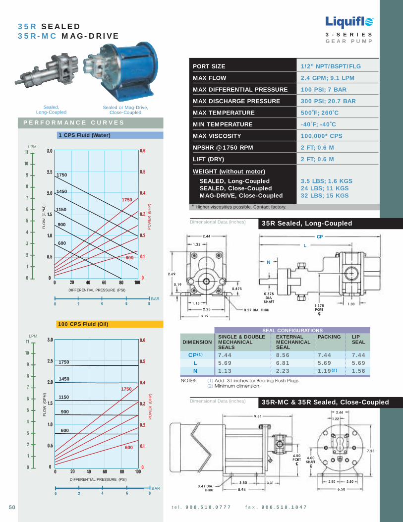
TM
0 2 4 6 8
BAR
DIFFERENTIAL PRESSURE (PSI)
3.0
2.5
2.0
1.5
1.0
0.5
080604020 1000
1750
1450
1150
900
PO
WE
R(B
HP
)
FLO
W(G
PM
)
1750
600
0.6
0.5
0.4
0.3
0.2
0.1
0
600
LPM11
10
9
8
7
6
5
4
3
2
1
0
3 5 R S E A L E D3 5 R - M C M A G - D R I VE
0 2 4 6 8
BAR
DIFFERENTIAL PRESSURE (PSI)
80604020 1000
1750
1450
1150
900
PO
WE
R(B
HP
)
FLO
W(G
PM
)
600
1750
3.0
2.5
2.0
1.5
1.0
0.5
0
600
0.6
0.5
0.4
0.3
0.2
0.1
0
LPM11
10
9
8
7
6
5
4
3
2
1
0
35R Sealed, Long-Coupled
35R-MC & 35R Sealed, Close-Coupled
100 CPS Fluid (Oil)
P E R F O R M A N C E C U R V E S
1 CPS Fluid (Water)
PORT SIZE 1/2” NPT/BSPT/FLG
MAX FLOW 2.4 GPM; 9.1 LPM
MAX DIFFERENTIAL PRESSURE 100 PSI; 7 BAR
MAX DISCHARGE PRESSURE 300 PSI; 20.7 BAR
MAX TEMPERATURE 500˚F; 260˚C
MIN TEMPERATURE -40˚F; -40˚C
MAX VISCOSITY 100,000* CPS
NPSHR @ 1750 RPM 2 FT; 0.6 M
LIFT (DRY) 2 FT; 0.6 M
WEIGHT (without motor)
SEALED, Long-Coupled 3.5 LBS; 1.6 KGSSEALED, Close-Coupled 24 LBS; 11 KGSMAG-DRIVE, Close-Coupled 32 LBS; 15 KGS
Dimensional Data (inches)
Dimensional Data (inches)
1.22
2.25
1.13
3.19
2.69
0.19
0.27 DIA. THRU
L
CP
N
1.00
0.375DIA.
SHAFT
0.875
9.81
7.25
5.94
3.50 3.31 2.50 2.50
6.50
2.44
1.22
0.41 DIA.THRU
2.44
1.375PORT
CL
4.50 PORT
CL
4.00 SHAFT
CL
3 - S E R I E SG E A R P U M P
* Higher viscosities possible. Contact factory.
t e l . 9 0 8 . 5 1 8 . 0 7 7 7 f a x . 9 0 8 . 5 1 8 . 1 8 4 750
NOTES: (1) Add .31 inches for Bearing Flush Plugs.(2) Minimum dimension.
SEAL CONFIGURATIONSSINGLE & DOUBLE EXTERNAL PACKING LIP
DIMENSION MECHANICAL MECHANICAL SEALSEALS SEAL
CP (1 ) 7 .44 8 .56 7 .44 7 .44L 5 .69 6 .81 5 .69 5 .69N 1 .13 2 .23 1 .19 (2 ) 1 .56
Sealed,Long-Coupled
Sealed or Mag-Drive,Close-Coupled

TM
9.81
7.25
2.44
1.22
4.50 PORT
CL
4.00 SHAFT
CL
PORT SIZE 1/2” NPT/BSPT/FLG
MAX FLOW 3.4 GPM; 13 LPM
MAX DIFFERENTIAL PRESSURE 100 PSI; 7 BAR
MAX DISCHARGE PRESSURE 300 PSI; 20.7 BAR
MAX TEMPERATURE 500˚F; 260˚C
MIN TEMPERATURE -40˚F; -40˚C
MAX VISCOSITY 100,000* CPS
NPSHR @ 1750 RPM 2 FT; 0.6 M
LIFT (DRY) 4 FT; 1.2 M
WEIGHT (without motor)SEALED, Long-Coupled 3.5 LBS; 1.6 KGSSEALED, Close-Coupled 24 LBS; 11 KGSMAG-DRIVE, Close-Coupled 32 LBS; 15 KGS
0 2 4 6 8
BAR
DIFFERENTIAL PRESSURE (PSI)
4.0
3.5
3.0
2.5
2.0
1.5
1.0
0.5
080604020 1000
1750
1450
1150
900
PO
WE
R(B
HP
)
FLO
W(G
PM
)
1750
600
600
LPM
15
12
9
6
3
0
0.8
0.7
0.6
0.5
0.4
0.3
0.2
0.1
0
100 CPS Fluid (Oil)
1 CPS Fluid (Water)
P E R F O R M A N C E C U R V E S
3 5 F S E A L E D3 5 F - M C M A G - D R I VE
35F Sealed, Long-Coupled
35F-MC & 35F Sealed, Close-Coupled
Dimensional Data (inches)
Dimensional Data (inches)
1.22
2.69
0.19
0.27 DIA. THRU
L
CP
N
1.00
0.375DIA.
SHAFT
0.875
2.44
2.25
1.13
3.19
1.375PORT
CL
3 - S E R I E SG E A R P U M P
* Higher viscosities possible. Contact factory.
t e l . 9 0 8 . 5 1 8 . 0 7 7 7 f a x . 9 0 8 . 5 1 8 . 1 8 4 751
5.94
3.50 3.31 2.50 2.50
6.500.41 DIA.
THRU0 2 4 6 8
BAR
DIFFERENTIAL PRESSURE (PSI)
80604020 1000
1750
1450
1150
900
PO
WE
R(B
HP
)
FLO
W(G
PM
)
600
1750
600
4.0
3.5
3.0
2.5
2.0
1.5
1.0
0.5
0
LPM
15
12
9
6
3
0
0.8
0.7
0.6
0.5
0.4
0.3
0.2
0.1
0
NOTES: (1) Add .31 inches for Bearing Flush Plugs.(2) Minimum dimension.
SEAL CONFIGURATIONSSINGLE & DOUBLE EXTERNAL PACKING LIP
DIMENSION MECHANICAL MECHANICAL SEALSEALS SEAL
CP (1 ) 7 .44 8 .56 7 .44 7 .44L 5 .69 6 .81 5 .69 5 .69N 1 .13 2 .23 1 .19 (2 ) 1 .56
Sealed,Long-Coupled
Sealed or Mag-Drive,Close-Coupled

DIFFERENTIAL PRESSURE (PSI)
10
9
8
7
6
5
4
3
2
1
080604020 1000
1750
1450
900
PO
WE
R(B
HP
)
FLO
W(G
PM
)
1750
600
600
1.6
1.4
1.2
1.0
0.8
0.6
0.4
0.2
0
1150
0 2 4 6 8
BAR
LPM
36
32
28
24
20
16
12
8
4
0
3 7 R S E A L E D3 7 R - M C M A G - D R I VE
37R Sealed, Long-Coupled
37R-MC & 37R Sealed, Close-Coupled
100 CPS Fluid (Oil)
P E R F O R M A N C E C U R V E S
1 CPS Fluid (Water)
PORT SIZE 3/4” NPT/BSPT/FLG
MAX FLOW 8.6 GPM; 33 LPM
MAX DIFFERENTIAL PRESSURE 100 PSI; 7 BAR
MAX DISCHARGE PRESSURE 225 PSI; 15.5 BAR
MAX TEMPERATURE 500˚F; 260˚C
MIN TEMPERATURE -40˚F; -40˚C
MAX VISCOSITY 100,000* CPS
NPSHR @ 1750 RPM 5.2 FT; 1.6 M
LIFT (DRY) 6 FT; 1.8 M
WEIGHT (without motor)SEALED, Long-Coupled 6.5 LBS; 2.9 KGSSEALED, Close-Coupled 29 LBS; 13 KGSMAG-DRIVE, Close-Coupled 36 LBS; 16 KGS
Dimensional Data (inches)
Dimensional Data (inches)
10.72
7.25
5.94
3.50 3.75 2.50
6.50
3.32
1.66
0.41 DIA.THRU
2.50
TM
1.66
3.32
3.94
0.19
0.28 DIA. THRU
L
CP
N
0.875
0.500SHAFTDIA.
1.25
1.31
3.19
2.622.000PORT
CL
4.75 PORT
CL
4.00 SHAFT
CL
3 - S E R I E SG E A R P U M P
* Higher viscosities possible. Contact factory.
52
10
9
8
7
6
5
4
3
2
1
0
DIFFERENTIAL PRESSURE (PSI)
80604020 1000
1750
1450
1150
900
PO
WE
R(B
HP
)
FLO
W(G
PM
)
600
1750
1.6
1.4
1.2
1.0
0.8
0.6
0.4
0.2
0
0 2 4 6 8
BAR
LPM
36
32
28
24
20
16
12
8
4
0
600
NOTES: (1) Add .31 inches for Bearing Flush Plugs.(2) Minimum dimension.
SEAL CONFIGURATIONSSINGLE & DOUBLE EXTERNAL PACKING LIP
DIMENSION MECHANICAL MECHANICAL SEALSEALS SEAL
CP (1 ) 8 .20 10 .32 8 .20 8 .20L 5 .98 8 .10 5 .98 5 .98N 1 .23 3 .35 1 .25 (2 ) 1 .56
Sealed,Long-Coupled
Sealed or Mag-Drive,Close-Coupled

PORT SIZE 3/4” NPT/BSPT/FLG
MAX FLOW 10.7 GPM; 40.5 LPM
MAX DIFFERENTIAL PRESSURE 100 PSI; 7 BAR
MAX DISCHARGE PRESSURE 225 PSI; 15.5 BAR
MAX TEMPERATURE 500˚F; 260˚C
MIN TEMPERATURE -40˚F; -40˚C
MAX VISCOSITY 100,000* CPS
NPSHR @ 1750 RPM 5.2 FT; 1.6 M
LIFT (DRY) 7 FT; 2.1 M
WEIGHT (without motor)SEALED, Long-Coupled 6.5 LBS; 2.9 KGSSEALED, Close-Coupled 29 LBS; 13 KGSMAG-DRIVE, Close-Coupled 36 LBS; 16 KGS
Dimensional Data (inches)
0 2 4 6 8
BAR
DIFFERENTIAL PRESSURE (PSI)
12
10
8
6
4
2
080604020 1000
1750
1450
900
PO
WE
R(B
HP
)
FLO
W(G
PM
)
1750
600
600
1150
1.8
1.6
1.4
1.2
1.0
0.8
0.6
0.4
0.2
0
LPM45
40
35
30
25
20
15
10
5
0
100 CPS Fluid (Oil)
1 CPS Fluid (Water)
P E R F O R M A N C E C U R V E S
3 7 F S E A L E D3 7 F - M C M A G - D R I VE
37F Sealed, Long-Coupled
37F-MC & 37F Sealed, Close-Coupled
Dimensional Data (inches)
TM
10.98
7.25
5.94
3.50 3.88 2.50
6.50
3.32
1.66
0.41 DIA.THRU
2.50
1.66
3.32
3.94
0.19
0.28 DIA. THRU
L
CP
N
0.875
0.500SHAFTDIA.
1.25
1.31
3.19
2.622.000PORT
CL
4.75 PORT
CL
4.00 SHAFT
CL
3 - S E R I E SG E A R P U M P
* Higher viscosities possible. Contact factory.
t e l . 9 0 8 . 5 1 8 . 0 7 7 7 f a x . 9 0 8 . 5 1 8 . 1 8 4 753
0 2 4 6 8
BAR
DIFFERENTIAL PRESSURE (PSI)
80604020 1000
1750
1450
1150
900
PO
WE
R(B
HP
)
FLO
W(G
PM
)
1750
12
10
8
6
4
2
0
1.8
1.6
1.4
1.2
1.0
0.8
0.6
0.4
0.2
0
600
LPM45
40
35
30
25
20
15
10
5
0
600
NOTES: (1) Add .31 inches for Bearing Flush Plugs.(2) Minimum dimension.
SEAL CONFIGURATIONSSINGLE & DOUBLE EXTERNAL PACKING LIP
DIMENSION MECHANICAL MECHANICAL SEALSEALS SEAL
CP (1 ) 8 .32 10 .44 8 .32 8 .32L 5 .98 8 .10 5 .98 5 .98N 1 .11 3 .23 1 .13 (2 ) 1 .44
Sealed,Long-Coupled
Sealed or Mag-Drive,Close-Coupled
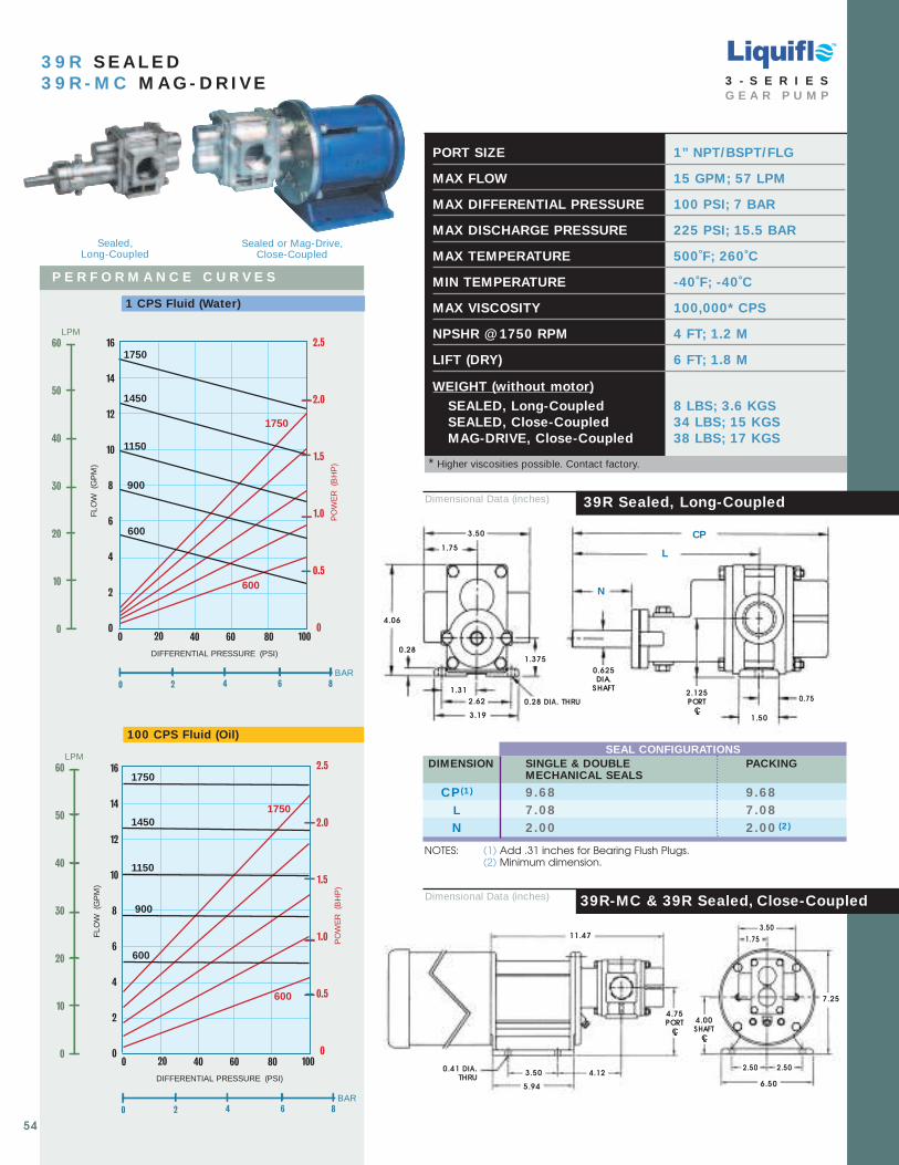
PORT SIZE 1” NPT/BSPT/FLG
MAX FLOW 15 GPM; 57 LPM
MAX DIFFERENTIAL PRESSURE 100 PSI; 7 BAR
MAX DISCHARGE PRESSURE 225 PSI; 15.5 BAR
MAX TEMPERATURE 500˚F; 260˚C
MIN TEMPERATURE -40˚F; -40˚C
MAX VISCOSITY 100,000* CPS
NPSHR @ 1750 RPM 4 FT; 1.2 M
LIFT (DRY) 6 FT; 1.8 M
WEIGHT (without motor)SEALED, Long-Coupled 8 LBS; 3.6 KGSSEALED, Close-Coupled 34 LBS; 15 KGSMAG-DRIVE, Close-Coupled 38 LBS; 17 KGS
11.47
7.25
5.94
3.50 4.122.50
6.50
3.50
0.41 DIA.THRU
2.50
Dimensional Data (inches)
0 2 4 6 8
BAR
DIFFERENTIAL PRESSURE (PSI)
16
14
12
10
8
6
4
2
080604020 1000
1750
1450
900
PO
WE
R(B
HP
)
FLO
W(G
PM
)
1750
600
600
LPM60
50
40
30
20
10
0
1150
2.5
2.0
1.5
1.0
0.5
0
3 9 R S E A L E D3 9 R - M C M A G - D R I VE
39R Sealed, Long-Coupled
39R-MC & 39R Sealed, Close-Coupled
100 CPS Fluid (Oil)
P E R F O R M A N C E C U R V E S
1 CPS Fluid (Water)
Dimensional Data (inches)
1.75
3.50
1.31
2.62
3.19
4.06
0.28
0.28 DIA. THRU
L
CP
1.50
0.625DIA.
SHAFT
0.75
NOTES: (1) Add .31 inches for Bearing Flush Plugs.(2) Minimum dimension.
SEAL CONFIGURATIONSDIMENSION SINGLE & DOUBLE PACKING
MECHANICAL SEALS
CP (1 ) 9 .68 9 .68L 7 .08 7 .08N 2 .00 2 .00 (2 )
TM
N
1.75
1.375
2.125PORT
CL
4.00 SHAFT
CL
4.75 PORT
CL
3 - S E R I E SG E A R P U M P
* Higher viscosities possible. Contact factory.
54
0 2 4 6 8
BAR
16
14
12
10
8
6
4
2
0
DIFFERENTIAL PRESSURE (PSI)
80604020 1000
1750
1450
1150
900
PO
WE
R(B
HP
)
FLO
W(G
PM
)
600
1750
600
2.5
2.0
1.5
1.0
0.5
0
LPM60
50
40
30
20
10
0
Sealed,Long-Coupled
Sealed or Mag-Drive,Close-Coupled

PORT SIZE 11/ 4” NPT/BSPT/FLG
MAX FLOW 21.5 GPM; 81.4 LPM
MAX DIFFERENTIAL PRESSURE 100 PSI; 7 BAR
MAX DISCHARGE PRESSURE 225 PSI; 15.5 BAR
MAX TEMPERATURE 500˚F; 260˚C
MIN TEMPERATURE -40˚F; -40˚C
MAX VISCOSITY 100,000* CPS
NPSHR @ 1750 RPM 3 FT; 0.9 M
LIFT (DRY) 14 FT; 4.2 M
WEIGHT (without motor)SEALED, Long-Coupled 10 LBS; 4.5 KGSSEALED, Close-Coupled 36 LBS; 16 KGSMAG-DRIVE, Close-Coupled 40 LBS; 18 KGS
DIFFERENTIAL PRESSURE (PSI)
25
20
15
10
5
0
80604020 1000
1750
1450
900
PO
WE
R(B
HP
)
FLO
W(G
PM
)
1750
600
600
LPM
90
80
70
60
50
40
30
20
10
0
1150
3.5
3.0
2.5
2.0
1.5
1.0
0.5
0
0 2 4 6 8
BAR
100 CPS Fluid (Oil)
1 CPS Fluid (Water)
P E R F O R M A N C E C U R V E S
3 9 F S E A L E D3 9 F - M C M A G - D R I VE
39F-MC & 39F Sealed, Close-Coupled Dimensional Data (inches)
Dimensional Data (inches)
12.22
7.25
5.94
3.50 4.502.50
6.50
2.00
4.00
0.41 DIA.THRU
2.50
2.00
4.00
1.31
2.62
3.19
4.06
0.28
0.28 DIA. THRU
N
CP
2.23
0.625DIA.
SHAFT
1.25
.63
1.375
39F Sealed, Long-Coupled
TM
2.125PORT
CL
L
4.75 PORT
CL
4.00 SHAFT
CL
3 - S E R I E SG E A R P U M P
* Higher viscosities possible. Contact factory.
t e l . 9 0 8 . 5 1 8 . 0 7 7 7 f a x . 9 0 8 . 5 1 8 . 1 8 4 755
25
20
15
10
5
0
DIFFERENTIAL PRESSURE (PSI)
80604020 1000
1750
1450
1150
900
PO
WE
R(B
HP
)
FLO
W(G
PM
)
600
1750
600
3.5
3.0
2.5
2.0
1.5
1.0
0.5
0
0 2 4 6 8
BAR
LPM
90
80
70
60
50
40
30
20
10
0
NOTES: (1) Add .31 inches for Bearing Flush Plugs.(2) Minimum dimension.
SEAL CONFIGURATIONSDIMENSION SINGLE & DOUBLE PACKING
MECHANICAL SEALS
CP (1 ) 10 .44 10 .44L 7 .47 7 .47N 2 .00 2 .00 (2 )
Sealed,Long-Coupled
Sealed or Mag-Drive,Close-Coupled
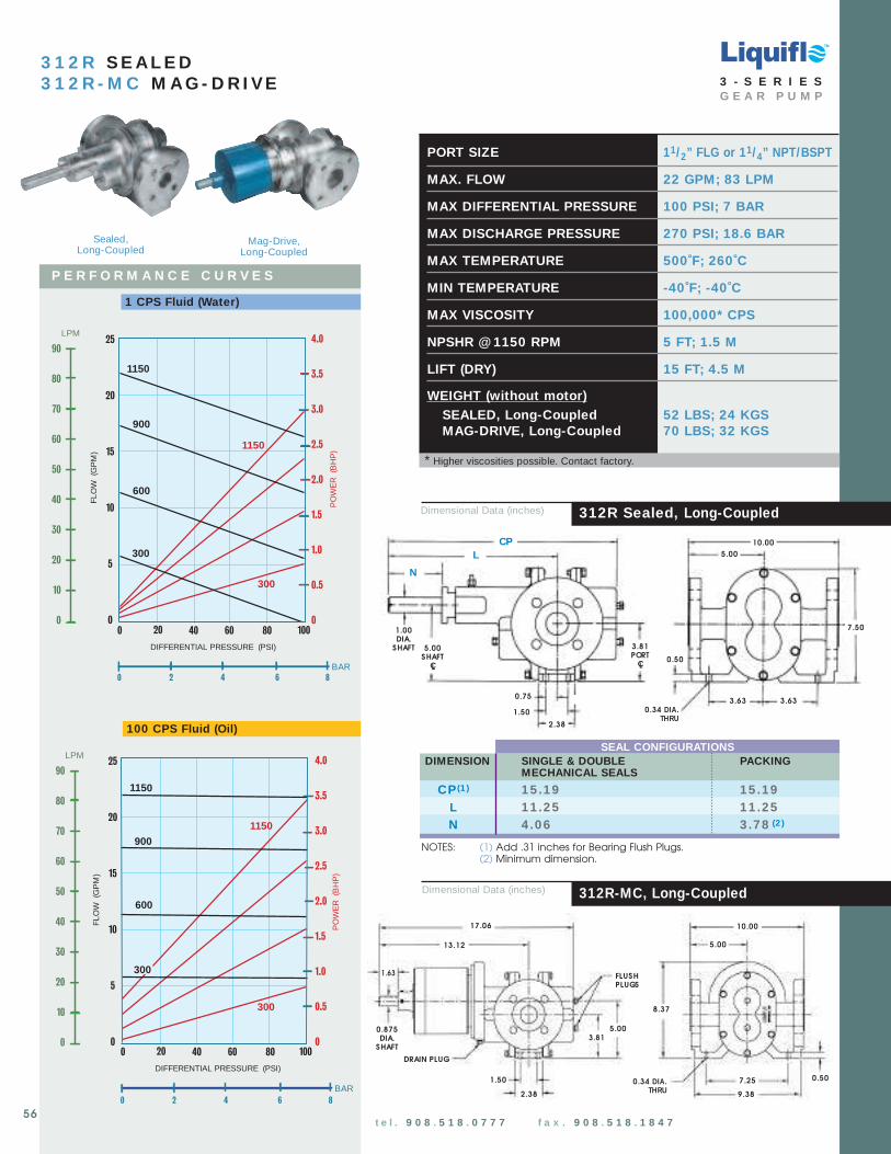
0.50
17.06
9.38
13.12
7.25
5.00
10.00
0.34 DIA. THRU
1.63
0.875DIA.
SHAFT
2.38
1.50
3.81
8.37
5.00
DRAIN PLUG
FLUSHPLUGS
TM
DIFFERENTIAL PRESSURE (PSI)
25
20
15
10
5
0
80604020 1000
900
PO
WE
R(B
HP
)
FLO
W(G
PM
)
1150
600
300
1150
4.0
3.5
3.0
2.5
2.0
1.5
1.0
0.5
0
300
0 2 4 6 8
BAR
LPM
90
80
70
60
50
40
30
20
10
0
3 1 2 R S E A L E D3 1 2 R - M C M A G - D R I VE
312R-MC, Long-Coupled
100 CPS Fluid (Oil)
P E R F O R M A N C E C U R V E S
1 CPS Fluid (Water)
PORT SIZE 11/ 2” FLG or 1 1/ 4” NPT/BSPT
MAX. FLOW 22 GPM; 83 LPM
MAX DIFFERENTIAL PRESSURE 100 PSI; 7 BAR
MAX DISCHARGE PRESSURE 270 PSI; 18.6 BAR
MAX TEMPERATURE 500˚F; 260˚C
MIN TEMPERATURE -40˚F; -40˚C
MAX VISCOSITY 100,000* CPS
NPSHR @ 1150 RPM 5 FT; 1.5 M
LIFT (DRY) 15 FT; 4.5 M
WEIGHT (without motor)SEALED, Long-Coupled 52 LBS; 24 KGSMAG-DRIVE, Long-Coupled 70 LBS; 32 KGS
Dimensional Data (inches)
CPL
1.00DIA.
SHAFT
7.50
0.34 DIA. THRU
5.00
0.50
1.50
3.63
5.00SHAFT
CL
2.38
0.753.63
10.00
N
3.81PORT
CL
Dimensional Data (inches) 312R Sealed, Long-Coupled
3 - S E R I E SG E A R P U M P
* Higher viscosities possible. Contact factory.
t e l . 9 0 8 . 5 1 8 . 0 7 7 7 f a x . 9 0 8 . 5 1 8 . 1 8 4 756
25
20
15
10
5
0
DIFFERENTIAL PRESSURE (PSI)
80604020 1000
1150
600
PO
WE
R(B
HP
)
FLO
W(G
PM
)
300
1150
300
4.0
3.5
3.0
2.5
2.0
1.5
1.0
0.5
0
900
0 2 4 8
BAR
LPM
90
80
70
60
50
40
30
20
10
0
6
NOTES: (1) Add .31 inches for Bearing Flush Plugs.(2) Minimum dimension.
SEAL CONFIGURATIONSDIMENSION SINGLE & DOUBLE PACKING
MECHANICAL SEALS
CP (1 ) 15 .19 15 .19L 11 .25 11 .25N 4 .06 3 .78 (2 )
Sealed,Long-Coupled
Mag-Drive,Long-Coupled
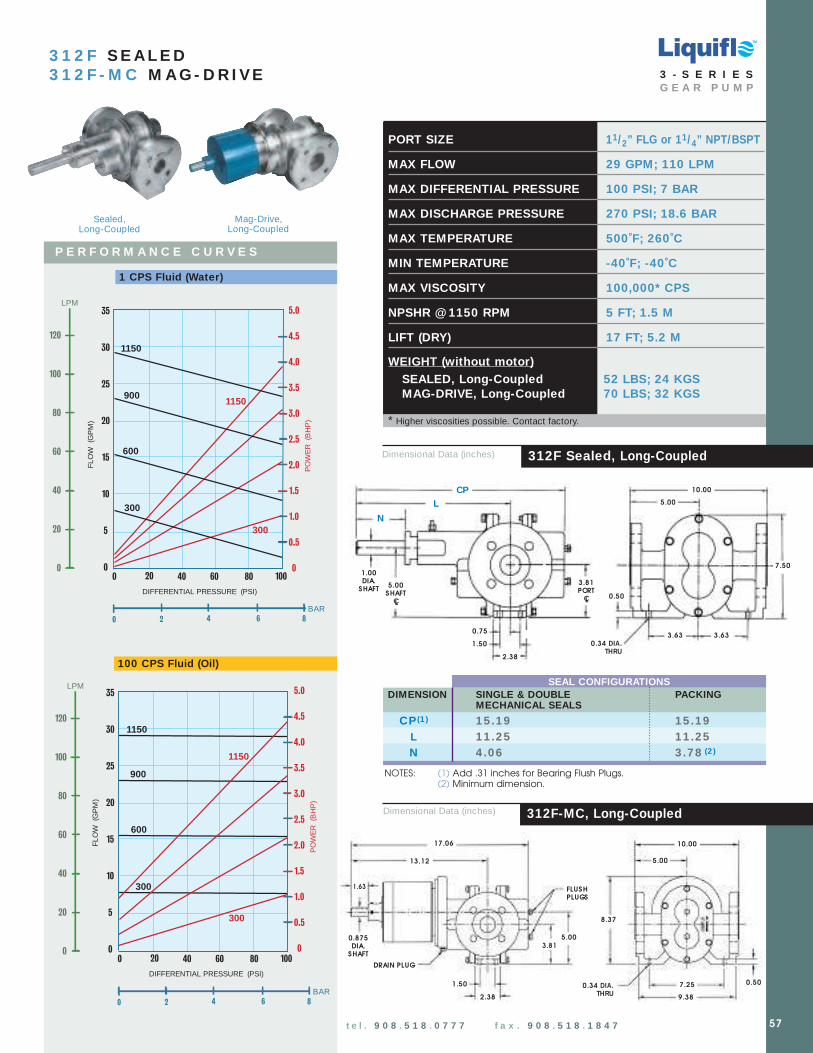
0.50
17.06
9.38
13.12
7.25
5.00
10.00
0.34 DIA. THRU
1.63
0.875DIA.
SHAFT
2.38
1.50
3.81
8.37
5.00
DRAIN PLUG
FLUSHPLUGS
TM
PORT SIZE 11/ 2” FLG or 1 1/ 4” NPT/BSPT
MAX FLOW 29 GPM; 110 LPM
MAX DIFFERENTIAL PRESSURE 100 PSI; 7 BAR
MAX DISCHARGE PRESSURE 270 PSI; 18.6 BAR
MAX TEMPERATURE 500˚F; 260˚C
MIN TEMPERATURE -40˚F; -40˚C
MAX VISCOSITY 100,000* CPS
NPSHR @ 1150 RPM 5 FT; 1.5 M
LIFT (DRY) 17 FT; 5.2 M
WEIGHT (without motor)SEALED, Long-Coupled 52 LBS; 24 KGSMAG-DRIVE, Long-Coupled 70 LBS; 32 KGS
DIFFERENTIAL PRESSURE (PSI)
35
30
25
20
15
10
5
080604020 1000
900
PO
WE
R(B
HP
)
FLO
W(G
PM
)
1150
600
300
1150
LPM
120
100
80
60
40
20
0
300
0 2 4 6 8
BAR
5.0
4.5
4.0
3.5
3.0
2.5
2.0
1.5
1.0
0.5
0
100 CPS Fluid (Oil)
1 CPS Fluid (Water)
P E R F O R M A N C E C U R V E S
3 1 2 F S E A L E D3 1 2 F - M C M A G - D R I VE
312F Sealed, Long-Coupled
312F-MC, Long-Coupled
Dimensional Data (inches)
CPL
1.00DIA.
SHAFT
7.50
0.34 DIA. THRU
5.00
0.50
1.50
3.63
5.00SHAFT
CL
2.38
0.753.63
10.00
N
3.81PORT
CL
3 - S E R I E SG E A R P U M P
Dimensional Data (inches)
* Higher viscosities possible. Contact factory.
t e l . 9 0 8 . 5 1 8 . 0 7 7 7 f a x . 9 0 8 . 5 1 8 . 1 8 4 7 57
0 2 4 6 8
BAR
DIFFERENTIAL PRESSURE (PSI)
80604020 1000
600
PO
WE
R(B
HP
)
FLO
W(G
PM
)
300
1150
35
30
25
20
15
10
5
0
300
5.0
4.5
4.0
3.5
3.0
2.5
2.0
1.5
1.0
0.5
0
900
1150
LPM
120
100
80
60
40
20
0
NOTES: (1) Add .31 inches for Bearing Flush Plugs.(2) Minimum dimension.
SEAL CONFIGURATIONSDIMENSION SINGLE & DOUBLE PACKING
MECHANICAL SEALS
CP (1 ) 15 .19 15 .19L 11 .25 11 .25N 4 .06 3 .78 (2 )
Sealed,Long-Coupled
Mag-Drive,Long-Coupled

0.50
19.06
7.25
14.12
3.815.00
10.00
0.52 DIA.THRU
0.875DIA.
SHAFT
4.25
1.63
3.00
9.38
8.37
5.00
FLUSHPLUGS
DRAIN PLUG
TM
0 2 4 6 8
BAR
DIFFERENTIAL PRESSURE (PSI)
80604020 1000
900
PO
WE
R(B
HP
)
FLO
W(G
PM
)
1150
600
300
1150
LPM
250
200
150
100
50
0
300
9
8
7
6
5
4
3
2
1
0
70
60
50
40
30
20
10
0
3 1 4 F S E A L E D3 1 4 F - M C M A G - D R I VE
314F Sealed, Long-Coupled
314F-MC, Long-Coupled
100 CPS Fluid (Oil)
P E R F O R M A N C E C U R V E S
1 CPS Fluid (Water)
PORT SIZE 21/ 2” FLG
MAX FLOW 58 GPM; 220 LPM
MAX DIFFERENTIAL PRESSURE 100 PSI; 7 BAR
MAX DISCHARGE PRESSURE 270 PSI; 18.6 BAR
MAX TEMPERATURE 500˚F; 260˚C
MIN TEMPERATURE -40˚F; -40˚C
MAX VISCOSITY 100,000* CPS
NPSHR @ 1150 RPM 3 FT; 0.9 M
LIFT (DRY) 20 FT; 6.1 M
WEIGHT (without motor)SEALED, Long-Coupled 67 LBS; 30 KGSMAG-DRIVE, Long-Coupled 85 LBS; 39 KGS
Dimensional Data (inches)
Dimensional Data (inches)
L
3.81PORT
CL
1.00DIA.
SHAFT
7.50
0.52 DIA.THRU
5.00
0.50
3.00
3.63
5.00SHAFT
CL
4.25
1.50 3.63
10.00
N
CP
3 - S E R I E SG E A R P U M P
* Higher viscosities possible. Contact factory.
58
0 2 4 6 8
BAR
DIFFERENTIAL PRESSURE (PSI)
80604020 1000
600
PO
WE
R(B
HP
)
FLO
W(G
PM
)
1150
300
70
60
50
40
30
20
10
0
1150
900
300
9
8
7
6
5
4
3
2
1
0
LPM
250
200
150
100
50
0
NOTES: (1) Add .31 inches for Bearing Flush Plugs.(2) Minimum dimension.
SEAL CONFIGURATIONSDIMENSION SINGLE & DOUBLE PACKING
MECHANICAL SEALS
CP (1 ) 17 .19 17 .19L 12 .25 12 .25N 4 .06 3 .78 (2 )
Sealed,Long-Coupled
Mag-Drive,Long-Coupled

2 - SE RI E S, 4 - SE RI E S & M AX - SE RI E S L I QU I FLO E X T E RN AL GE AR P U M P S
L I Q U I F L O C H E M I C A L P R O C E S S I N G P U M P S
TM
59t e l . 9 0 8 . 5 1 8 . 0 7 7 7 f a x . 9 0 8 . 5 1 8 . 1 8 4 7 w w w . l i q u i f l o . c o m
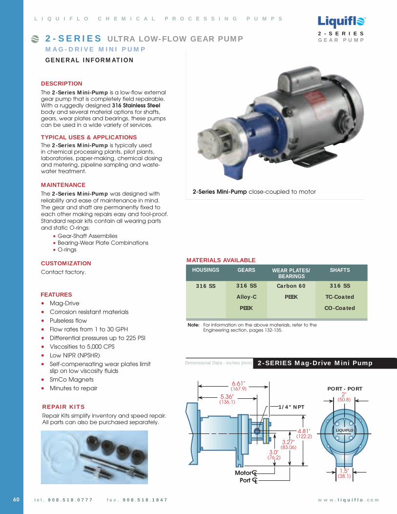
60
2 -SERIES M ag-Drive M ini Pump
TM
t e l . 9 0 8 . 5 1 8 . 0 7 7 7 f a x . 9 0 8 . 5 1 8 . 1 8 4 7 w w w . l i q u i f l o . c o m
REPAIR KITS
Repair Kits simplify inventory and speed repair.All parts can also be purchased separately.
FEATURES• Mag-Drive
• Corrosion resistant materials
• Pulseless flow
• Flow rates from 1 to 30 GPH
• Differential pressures up to 225 PSI
• Viscosities to 5,000 CPS
• Low NIPR (NPSHR)
• Self-compensating wear plates limit slip on low viscosity fluids
• SmCo Magnets
• Minutes to repair
L I Q U I F L O C H E M I C A L P R O C E S S I N G P U M P S
DESCRIPTION
The 2-Series M ini-Pump is a low-flow externalgear pump that is completely field repairable.With a ruggedly designed 316 Stainless Steelbody and several material options for shafts,gears, wear plates and bearings, these pumpscan be used in a wide variety of services.
TYPICAL USES & APPLICATIONSThe 2-Series M ini-Pump is typically usedin chemical processing plants, pilot plants, laboratories, paper-making, chemical dosing and metering, pipeline sampling and waste-water treatment.
MAINTENANCEThe 2-Series M ini-Pump was designed with reliability and ease of maintenance in mind. The gear and shaft are permanently fixed toeach other making repairs easy and fool-proof.Standard repair kits contain all wearing parts and static O-rings:
• Gear-Shaft Assemblies• Bearing-Wear Plate Combinations• O-rings
CUSTOMIZATIONContact factory. GEARS
316 SS
Alloy-C
PEEK
WEAR PLATES/BEARINGS
Carbon 60
PEEK
SHAFTS
316 SS
TC-Coated
CO-Coated
HOUSINGS
316 SS
MATERIALS AVAILABLE
2 - S E R I E S ULTRA LOW-FLOW GEAR PUM PM A G - D R I V E M I N I P U M P
GE N E RAL I N FORM AT I ON
Dimensional Data - inches (mm)
LIQUIFLO
2"�(50.8)
3.0"�(76.2)
3.27"�(83.06)
1 / 4 " N PT
5.36"�(136.1)
PORT - PORT
Motor
Port CL
CL1.5"�
(38.1)
4.81"�(122.2)
6.61"�(167.9)
2-Series Mini-Pump close-coupled to motor
2 - S E R I E SG E A R P U M P
Note: For information on the above materials, refer to the Engineering section, pages 132-135.

2-Series Mag-Drive Gear Pump
t e l . 9 0 8 . 5 1 8 . 0 7 7 7 f a x . 9 0 8 - 5 1 8 - 1 8 4 7 w w w . l i q u i f l o . c o m
TM
2 - S E R I E SG E A R P U M P
2
F = Full Capacity nR = Reduced Capacity n
S = 316 SS NPT nX = 316 SS BSPT n
1 = Alloy-C n6 = 316 SS nP = PEEK n
1 = Alloy-C n6 = 316 SS nP = PEEK n
E = Carbon 60 nP = PEEK n
0 = 0.500” (NEMA 48C) n1 = 14 mm (IEC 71 - B14 Face) n2 = 0.625” (NEMA 56C/56HC) n
0 = 316 SS (uncoated) n1 = 316 SS - Chrome Oxide Coated n2 = 316 SS - Tungsten Carbide Coated n
0 = Teflon nV = Viton nK = Kalrez n
X = 10 in-lbs n
- 8 = Temperature Trim n
3PositionBasic Material &
Port Type
4PositionDrive Gear
5PositionIdler Gear
6PositionWear Plates & Bearings
Combination
7PositionOuter Magnet Bore
(Motor Frame)
9PositionO-Rings
10PositionMagnetic Coupling
Pump Model1PositionModel
Sample Model No.
Position No.
2 S 6 P E 2 0 0 X
1 2 3 4 5 6 7 8 9 10
PUMP MODEL CODING
2F S 6 P E 2 0 0 X
Pump Model 2F 2F Pump
Housing Mat’l S 316 SS NPT
Drive Gear Mat’l 6 316 SS
Idler Gear Mat’l P PEEK
Wear Plates/Bearings E Carbon 60
Outer Magnet Bore 2 .625” (56C motor)
Shafts 0 Non-coated
O-Rings 0 Teflon
Magnetic Coupling X MCX
1 & 2 3 4 5 6 7 8 9 10
1 & 2
3
4
5
6
7
8
9
10
Liquiflo’s Model Code describesboth the pump’s size and materials selected. This model code is required for the future identification of your pump when reordering either a pump or replacement parts. Model code is permanentlystamped into pump housing.
n Available
U Not Available
CF Contact Factory
EXAM PLE:2FS6PE200X, designates a Model 2F Mag-Drive Pump.
Pos. Description Selection
8PositionShafts
2PositionModel
F
Liquiflo 2-Series Gear PumpsSelection & Availability
Wear Plates& Bearings Combo
Idler Gear
6Shafts
Outer MagnetBore
7
O-RingsMagneticCoupling
109
5
Drive Gear
4
MotorShaft
1
2
3
Model,Housing& Port Type
8
SuffixTrim Option
61

10 CPS Fluid (Oil)2 F
100 CPS Fluid (Oil)
35
30
25
20
15
10
5
0
1750
1450
1150
900 F
LO
W (G
PH
)
600
1750
LPH
140
120
100
80
60
40
20
0
0.21
0.18
0.15
0.12
0.09
0.06
0.03
0
DIFFERENTIAL PRESSURE (PSI)
100755025 2000 175150125 225
0 2 4 6 8
BAR
10 12 14 16
PO
WE
R (B
HP
)
600
35
30
25
20
15
10
5
0
1750
1450
1150
900
FL
OW
(G
PH
)
LPH
140
120
100
80
60
40
20
0
DIFFERENTIAL PRESSURE (PSI)
100755025 2000 175150125 225
0 2 4 6 8
BAR
10 12 14 16
PO
WE
R (B
HP
)
600
0.21
0.18
0.15
0.12
0.09
0.06
0.03
0
1750
600
TM
2 - S E R I E SG E A R P U M P
10 CPS Fluid (Oil)
P E R F O R M A N C E C U R V E S
2 R
100 CPS Fluid (Oil)
L I Q U I F L O C H E M I C A L P R O C E S S I N G P U M P S
2 - S E R I E S M ag-Drive M ini Pump
62
20
18
16
14
12
10
8
6
4
2
0
1750
1450
1150
900
FL
OW
(G
PH
)
600
1750
LPH
80
70
60
50
40
30
20
10
0
0.12
0.10
0.08
0.06
0.04
0.02
0
DIFFERENTIAL PRESSURE (PSI)
100755025 2000 175150125 225
0 2 4 6 8
BAR
10 12 14 16
PO
WE
R (B
HP
)
600
20
18
16
14
12
10
8
6
4
2
0
1750
1450
1150
900
FL
OW
(G
PH
)
600
1750
LPH
80
70
60
50
40
30
20
10
0
0.14
0.12
0.10
0.08
0.06
0.04
0.02
0
DIFFERENTIAL PRESSURE (PSI)
100755025 2000 175150125 225
0 2 4 6 8
BAR
10 12 14 16
PO
WE
R
(BH
P)
600
MODEL 2R (Reduced) 2F (Full)
PORT SIZE 1/4” NPT/BSPT 1/4” NPT/BSPTMAX FLOW 17 GPH; 64 LPH 32.5 GPH; 123 LPHMAX DIFFERENTIAL PRESSURE 225 PSI; 15.5 BAR 225 PSI; 15.5 BARMAX DISCHARGE PRESSURE 300 PSI; 20.7 BAR 300 PSI; 20.7 BARMAX TEMPERATURE 500˚F; 260˚C 500˚F; 260˚CMIN TEMPERATURE -40˚F; -40˚C -40˚F; -40˚CMAX VISCOSITY (300 RPM) 5,000 CPS 5,000 CPS
NPSHR @ 1750 RPM 3 FT; 0.9 M 3 FT; 0.9 MLIFT (DRY) negligible negligible
WEIGHT (without motor) 5 LBS; 2.3 KGS 5 LBS; 2.3 KGS
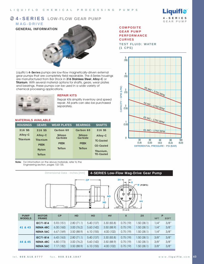
63t e l . 9 0 8 . 5 1 8 . 0 7 7 7 f a x . 9 0 8 . 5 1 8 . 1 8 4 7 w w w . l i q u i f l o . c o m
L I Q U I F L O C H E M I C A L P R O C E S S I N G P U M P S
C OM P OSI T E GE AR P U M PP E RFORM AN C EC U RVE S
T E ST FLU I D : WAT E R(1 C P S)
5
4
3
2
1
080
(5.5)60
(4.1)40
(2.8)20
(1.4)
DIFFERENTIAL PRESSURE • PSI (BAR)
CA
PA
CIT
Y •
GP
M (L
PM
)
45-MC • 1750 RPM
43-MC • 1750 RPM
100(6.9)
44-MC • 1750 RPM
41-MC • 1750 RPM
(19)
(15)
(11)
(7.6)
(3.8)
4 - S E R I E S LOW-FLOW GEAR PUM PM A G - D R I V EGENERAL INFORM ATION
Liquiflo’s 4-Series pumps are low-flow magnetically-driven externalgear pumps that are completely field repairable. The 4-Series housingsare manufactured from Bar Stock in 316 Stainless Steel, Alloy-C orTitanium. With several material options for shafts, gears, wear platesand bearings, these pumps can be used in a wide variety of chemical processing applications.
REPAIR KITSRepair Kits simplify inventory and speedrepair. All parts can also be purchased separately.
WEAR PLATES
Carbon 60
SiliconCarbide
PEEK
Teflon
BEARINGS
Carbon 60
SiliconCarbide
PEEK
Teflon
SHAFTS
316 SS
Alloy-C
TC-Coated
CO-Coated
Titanium,TO-Coated
HOUSINGS
316 SS
Alloy-C
Titanium
GEARS
316 SS
Alloy-C
Titanium
PEEK
Ryton
Teflon
MATERIALS AVAILABLE
4 - S E R I E SG E A R P U M P
Note: For information on the above materials, refer to the Engineering section, pages 132-135.
HO
CP
P (PORTS)
HVHD
2XX
1.50
4-SERIES Low-Flow Mag-Drive Gear PumpDimensional Data - inches [mm]
PUMP MOTOR CP HD HO HV X 2X PMODELS FRAME NPT BSPT
IEC71-B14 5.93 [151] 2.80 [71.1] 5.40 [137] 3.30 [83.8] 0.75 [19] 1.50 [38.1] 1/4” 3/8”
41 & 43 NEMA 48C 6.30 [160] 3.00 [76.2] 5.60 [142] 3.50 [88.9] 0.75 [19] 1.50 [38.1] 1/4” 3/8”
NEMA 56C 6.67 [169] 3.50 [88.9] 6.10 [155] 4.00 [102] 0.75 [19] 1.50 [38.1] 1/4” 3/8”
IEC71-B14 6.43 [163] 2.80 [71.1] 5.40 [137] 3.30 [83.8] 0.75 [19] 1.50 [38.1] 3/8” 3/8”
44 & 45 NEMA 48C 6.80 [173] 3.00 [76.2] 5.60 [142] 3.50 [88.9] 0.75 [19] 1.50 [38.1] 3/8” 3/8”
NEMA 56C 7.17 [182] 3.50 [88.9] 6.10 [155] 4.00 [102] 0.75 [19] 1.50 [38.1] 3/8” 3/8”
TM

64
PUMP MODEL CODING
Sample Model No.
Position No.
43 S 6 P E E N 2 0 01 2 3 4 5 6 7 8 9 10
41 43 44 45
S = 316 SS NPT n n n nX = 316 SS BSPT n n n nH = Alloy-C NPT n n n nY = Alloy-C BSPT n n n nT = Titanium NPT n n n nZ = Titanium BSPT n n n n
1 = Alloy-C n n n n3 = Teflon CF n n n4 = Titanium n n n n6 = 316 SS n n n nP = PEEK n n n n
1 = Alloy-C n n n n3 = Teflon CF n n n4 = Titanium n n n n6 = 316 SS n n n n8 = Ryton n n n nP = PEEK n n n n
3 = Teflon n n n n4 = Ceramic (SiC) n n n nE = Carbon 60 n n n nP = PEEK n n n n
3 = Teflon n n n nB = Silicon Carbide n n n nE = Carbon 60 n n n nP = PEEK n n n n
N = 20 in-lbs n n n nR = 30 in-lbs n n n n
0 = .500” (NEMA 48C) n n n n1 = 14 mm (IEC 71 - B14 Face) n n n n2 = .625” (NEMA 56C/56HC) n n n n
0 = Material Same as Housing (uncoated)* n n n nA = Chrome Oxide Coated n n n nC = Tungsten Carbide Coated n n n n
0 = No Motor n n n nA = 0.25 Hp/1750 RPM - TEFC-AC n n n nB = 0.25 Hp/1150 RPM - TEFC-AC n n n nC = 0.25 Hp/1750 RPM - TENV-DC w/ SCR Control n n n n
- 8 = Temperature Trim n n n n- 9D = Viscosity Trim (double clearance) n n n n- 9T = Viscosity Trim (triple clearance) n n n n
* Titanium pumps have TiO2-Coated Shafts as standard
2PositionBasic Material &
Port Type
3PositionDrive Gear
4PositionIdler Gear
5PositionWear Plates
6PositionBearings
7PositionMagnetic Coupling
8PositionOuter Magnet Bore
(Motor Frame)
9PositionShafts
10PositionMotor
Pump Model1PositionModel
43 S 6 P E E N 2 0 0
Pump Model 43 43 Pump
Housing Mat’l S 316 SS NPT
Drive Gear Mat’l 6 316 SS
Idler Gear Mat’l P PEEK
Wear Plate Mat’l E Carbon 60
Bearing Mat’l E Carbon 60
Magnetic Coupling N MCN
Outer Magnet Bore 2 .625” (56C motor)
Shafts 0 Non-coated
Motor 0 None
1 2 3 4 5 6 7 8 9 10
1
2
3
4
5
6
7
8
9
10
Liquiflo’s Model Code describesboth the pump’s size and materials selected. This model code is required for the future identification of yourpump when reordering either a pump or replacement parts. Model code ispermanently stamped into pumphousing.
n Available
U Not Available
CF Contact Factory
EXAM PLE:43S6PEEN200, designates aModel 43 Mag-Drive Pump.
Pos. Description Selection
Liquiflo 4-Series Gear PumpsSelection & Availability
Wear Plates
IdlerGear
Model,Housing
& Port Type
DriveGear
1 2
3
4
5
Bearings
InnerMagnet
6
7
9
10
Outer MagnetBore Size(not shown)
Shafts(not shown)
Motor(not shown)
8
4-Series Mag-Drive Gear Pump
4 - S E R I E SG E A R P U M P
SuffixTrim Options
TM

DIFFERENTIAL PRESSURE (PSI)
0.6
0.5
0.4
0.3
0.2
0.1
0806040200
1750
1450
FLO
W (
GP
M)
600
1750 LPM
2.0
1.8
1.6
1.4
1.2
1.0
0.8
0.6
0.4
0.2
0
0 2 4 6 8
BAR
100
0.12
0.10
0.08
0.06
0.04
0.02
0
PO
WE
R (
BH
P)
900
600
1150
4 - S E R I E S M A G - D R I V E G E A R P U M P
1 CPS Fluid (W ater)
41-MC
0 2 4 6 8
BAR
DIFFERENTIAL PRESSURE (PSI)
1.6
1.4
1.2
1.0
0.8
0.6
0.4
0.2
0
80604020 1000
1750
1450
1150
900
PO
WE
R (
BH
P)
FLO
W (
GP
M)
600
1750
0.4
0.3
0.2
0.1
0
600
LPM
6
5
4
3
2
1
0
43-MC
0 2 4 6 8
BAR
DIFFERENTIAL PRESSURE (PSI)
4.0
3.5
3.0
2.5
2.0
1.5
1.0
0.5
080604020 1000
1750
1450
1150
900
PO
WE
R (
BH
P)
FLO
W (
GP
M)
1750
600
600
LPM
15
12
9
6
3
0
0.8
0.7
0.6
0.5
0.4
0.3
0.2
0.1
0
0 2 4 6 8
BAR
DIFFERENTIAL PRESSURE (PSI)
3.0
2.5
2.0
1.5
1.0
0.5
080604020 1000
1750
1450
1150
900
PO
WE
R (
BH
P)
FLO
W (
GP
M)
1750
600
0.6
0.5
0.4
0.3
0.2
0.1
0
600
LPM11
10
9
8
7
6
5
4
3
2
1
0
44-MC 45-MC
TM
t e l . 9 0 8 . 5 1 8 . 0 7 7 7 f a x . 9 0 8 . 5 1 8 . 1 8 4 7 w w w . l i q u i f l o . c o m 65
4 - S E R I E SG E A R P U M P
DIFFERENTIAL PRESSURE (PSI)
0.6
0.5
0.4
0.3
0.2
0.1
0806040200
1750
1450
FLO
W (
GP
M)
600
1750 LPM
2.0
1.8
1.6
1.4
1.2
1.0
0.8
0.6
0.4
0.2
0
0 2 4 6 8
BAR
100
0.12
0.10
0.08
0.06
0.04
0.02
0
PO
WE
R (
BH
P)
600
900
1150
100 CPS Fluid (Oil)
41-MC
0 2 4 6 8
BAR
DIFFERENTIAL PRESSURE (PSI)
80604020 1000
1750
1450
1150
900
PO
WE
R (
BH
P)
FLO
W (
GP
M)
600
1750
600
1.6
1.4
1.2
1.0
0.8
0.6
0.4
0.2
0
LPM
6
5
4
3
2
1
0
0.4
0.3
0.2
0.1
0
43-MC
0 2 4 6 8
BAR
DIFFERENTIAL PRESSURE (PSI)
80604020 1000
1750
1450
1150
900
PO
WE
R (
BH
P)
FLO
W (
GP
M)
600
1750
600
4.0
3.5
3.0
2.5
2.0
1.5
1.0
0.5
0
LPM
15
12
9
6
3
0
0.8
0.7
0.6
0.5
0.4
0.3
0.2
0.1
0
0 2 4 6 8
BAR
DIFFERENTIAL PRESSURE (PSI)
80604020 1000
1750
1450
1150
900
PO
WE
R (
BH
P)
FLO
W (
GP
M)
600
1750
3.0
2.5
2.0
1.5
1.0
0.5
0
600
0.6
0.5
0.4
0.3
0.2
0.1
0
LPM11
10
9
8
7
6
5
4
3
2
1
0
44-MC 45-MC
MODEL 41 43 44 45
Port Size 1 / 4 ” NPT/3 / 8 ” BSPT 1 / 4 ” NPT/3 / 8 ” BSPT 3 / 8 ” NPT/BSPT 3 / 8 ” NPT/BSPT
Max Flow @ 1750 RPM 0 .5 GPM (1 .9 LPM) 1 .4 GPM (5 .3 LPM) 2 .4 GPM (9 .1 LPM) 3 .4 GPM (13 LPM)
Max Diff. Press. 100 PSI (7 BAR) 100 PSI (7 BAR) 100 PSI (7 BAR) 100 PSI (7 BAR)
Max Discharge Press. 300 PSI (21 BAR) 300 PSI (21 BAR) 300 PSI (21 BAR) 300 PSI (21 BAR)
Max Temperature 500˚F (260˚C) 500˚F (260˚C) 500˚F (260˚C) 500˚F (260˚C)
Min Temperature -40˚F (-40˚C) -40˚F (-40˚C) -40˚F (-40˚C) -40˚F (-40˚C)
Max Viscosity@ 300 RPM 4,500 CPS 3,700 CPS 2,000 CPS 1,000 CPS
NPSHR @ 1750 RPM 4.5 FT (1.4 M) 3 FT (0.9 M) 3 FT (0.9 M) 2 FT (0.6 M)
Lift (Dry) 0.5 FT (0.15 M) 1.5 FT (0.45 M) 2.0 FT (0.6 M) 4 FT (1.2 M)
Weight 11 LBS (5 KGS) 11 LBS (5 KGS) 13 LBS (6 KGS) 13 LBS (6 KGS)
4-Series Specifica tions
4-SERIES PERFORMANCE CURVES
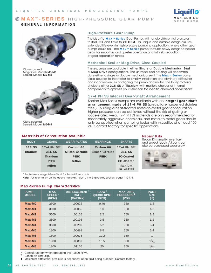
t e l . 9 0 8 . 5 1 8 . 0 7 7 7 f a x . 9 0 8 . 5 1 8 . 1 8 4 7 w w w . l i q u i f l o . c o m
L I Q U I F L O C H E M I C A L P R O C E S S I N G P U M P S
M A X - S E R I E SG E A R P U M P
66
M A X ™ - S E R I E S H I G H - P R E S S U R E G E A R P U M PG E N E R A L I N F O R M A T I O N
High-Pressure Gear Pump
The Liquiflo M ax ™ Series Gear Pumps will handle differential pressures to 350 PSI and flows to 20 GPM . Its unique and durable design assuresextended life even in high-pressure pumping applications where other gearpumps could fail. The M ax ™ Series pump features newly designed helicalgears for smoother and quieter operation and intrinsic reductionof gear separation forces.
M echanica l Sea l or M ag-Drive, Close-Coupled
These pumps are available in either Single or Double M echanica l Sea lor M ag-Drive configurations. The universal seal housing will accommo-date either a single or double mechanical seal. The M ax ™ Series pump close-couples to the motor to simplify installation and eliminate difficultiesand inconveniences of aligning the pump and motor. The body materialchoice is either 316 SS or Titanium with multiple choices of internal components to optimize your selection for specific chemical applications.
M ateria ls of Construction Ava ilable
BODY GEARS WEAR PLATES BEARINGS SHAFTS
316 SS 17-4 PH SS* Carbon 60 Carbon 60 17-4 PH SS*
Titanium 316 SS Silicon Carbide Silicon Carbide 316 SS
Titanium PEEK PEEK TC-Coated
PEEK Teflon CO-Coated
Teflon Titanium,TO-Coated
* Available as Integral Gear-Shaft for Sealed Pumps only.
Note: For information on the above materials, refer to the Engineering section, pages 132-135.
M ax -Series Pump Characteristics
PUMP MAX DISPLACEMENT † FLOW † MAX DIFF. PORTMODEL SPEED* RATE @1800 RPM PRESSUREt SIZE
(RPM) (Gal/Rev) (GPM) (PSI) (in)
Max-M0 3600 .00022 0.40 350 1/2
Max-M1 3600 .00055 1.0 350 1/2
Max-M2 3600 .00138 2.5 350 1/2
Max-M3 3600 .00193 3.5 350 1/2
Max-M4 3600 .00289 5.2 350 3/4
Max-M5 1800 .00491 8.8 350 3/4
Max-M6 1800 .00675 12.2 350 1
Max-M7 1800 .00859 15.5 350 11/4
Max-M8 1800 .01105 20 350 11/2
* Consult factory when operating over 1800 RPM.† Based on zero slip.t Maximum differential pressure is dependent upon fluid being pumped. Contact factory.
Close-coupledMag-Drive: Models M0-M8Sealed: Models M5-M8
Close-coupledSealed: Models M0-M4
Repa ir KitsRepair Kits simplify inventoryand speed repair. All parts canalso be purchased separately.
17-4 PH SS Integra l Gear-Sha ft ArrangementSealed Max-Series pumps are available with an integra l gear-sha fta r rangement made of 17 -4 PH SS (precipitate hardened stainlesssteel). By using a heat-treated metal-to-metal gear configuration,higher pressures can be achieved without the risk of galling oraccelerated wear. 17-4 PH SS materials are only recommended formoderately aggressive chemicals, and metal-to-metal gears shouldonly be applied when pumping liquids with viscosities of at least 100cP. Contact factory for specific applications.
TM

M A X - S E R I E SG E A R P U M P
t e l . 9 0 8 . 5 1 8 . 0 7 7 7 f a x . 9 0 8 . 5 1 8 . 1 8 4 7 w w w . l i q u i f l o . c o m 67
M ag-Drive Models M0–M8
• Hardened Stainless Steel Alignment Pins
Helical Gears for smoother and quieter operation
316 SS or Titanium Shafts (various coatings available)
Heavy Duty Cast Iron mounting bracket supports pump & motor
Heavy duty bolting andrugged construction
• Solid 316 SS or TitaniumHousings
• Oversized Bearings forhigh-pressure applications
• High-strength SmCo magnets
Relieved Wear Plates
1
2
4
5
6
7
8
3
Sea led Models M0–M4
• Hardened Stainless Steel Alignment Pins
Helical Gears for smootherand quieter operation –also available as Hardened Integral Gear-Shaft
316 SS shafts (coatings available)
or 17-4 PH SS IntegralGear-Shaft
All Stainless Steel mountingbracket resists corrosion
Heavy duty bolting &rugged construction
316 Stainless SteelHousings
Oversized Bearings forhigh-pressure applications
• Seal Chamber can acceptSingle or DoubleMechanical Seal
Relieved Wear Plates
1
2
3
4
5
6
7
L I Q U I F L O C H E M I C A L P R O C E S S I N G P U M P S
9
6 1 43 8
9
2
7
5
6 1
4
3
8
2
7
5
8
9
M A X - S E R I E S D E S I G N F E A T U R E S
9
TM

68
PUMP MODEL CODING
Liquiflo’s Model Code describesboth the pump’s size and materialsselected. This model code is required for the future identification of yourpump when reordering either a pump or replacement parts. Model code ispermanently stamped into pumphousing.
n Available
U Not Available
CF Contact Factory
Liquiflo Max ®-Series Gear PumpsSelection & Availability
t e l . 9 0 8 . 5 1 8 . 0 7 7 7 f a x . 9 0 8 . 5 1 8 . 1 8 4 7
2PositionBasic Material &
Port Type
3PositionDrive Gear
4PositionIdler Gear
5PositionWear Plates
6PositionBearings
7PositionMotor Frame
Size
8PositionSeal Type* or
Mag-Drive
9PositionBearing Flush
10PositionShafts
11PositionO-Rings
(Housing - Seal Seats)
12PositionMagnetic Coupling(Mag-Drive Only)
SuffixTrim Options
Pump Model1PositionModel
Flanges available:
ANSI, DIN, JIS, or slip joint flanges conforming to the dimensions of the standard.
CONNECTION SIZES
M0 – M3 M4 / M5 M6 M7 M8
THREADED 1/2 3/4 1 11/4 11/2
FLANGED 1/2 3/4 1 11/4 11/2
M5 S 6 P E E 0 U 0 0 0
Pump Model M5 M5 Pump
Housing Mat’l S 316 SS NPT
Drive Gear Mat’l 6 316 SS
Idler Gear Mat’l P PEEK
Wear Plate Mat’l E Carbon 60
Bearing Mat’l E Carbon 60
Motor Frame Size 0 0.625” (56C)
Seal Type U Single-Int, Carbon-SiC
Bearing Flush 0 None
Shafts 0 316 SS (uncoated)
O-Rings 0 Teflon
N/A
1 2 3 4 5 6 7 8 9 10 11 12
1
2
3
4
5
6
7
8
9
10
11
12
Pos. Description Selection
EXAM PLE:M5S6PEE0U000, designates a ModelM5 Pump with Single Mechanical Seal.
Sample Model No.
Position No.
M5 S 6 P E E U 0 0 0
1 2 3 4 5 6 7 8 9 10 11 12
0
M 0 M 1 M 2 M 3 M 4 M 5 M 6 M 7 M 8
S = 316 SS NPT n n n n n n n n n
L = 316 SS Flanged n n n n n n n n n
X = 316 SS BSPT n n n n n n n n n
T = Titanium NPT CF CF CF CF n CF n CF CFR = Titanium Flanged CF CF CF CF n CF n CF n
Z = Titanium BSPT CF CF CF CF n CF n CF CF
4 = Titanium CF CF CF CF n CF n CF n
6 = 316 SS n n n n n n n n n
9 = 17-4 PH SS Integral Gear-Shaft† n n n n n n n n n
P = PEEK n n n n n n n n n
3 = Teflon n n n n n n n n n
6 = 316 SS n n n n n n n n n
9 = 17-4 PH SS Integral Gear-Shaft† n n n n n n n n n
P = PEEK n n n n n n n n n
3 = Teflon n n n n n n n n n
4 = Ceramic (SiC) n n n n n n n n n
E = Carbon 60 n n n n n n n n n
P = PEEK n n n n n n n n n
B = Silicon Carbide n n n n n n n n n
E = Carbon 60 n n n n n n n n n
P = PEEK n n n n n n n n n
0 = 0.625” (NEMA 56C/56HC) n n n n n n n n n
1 = 0.875” (NEMA 143/145TC) n n n n n n n n n
2 = 14 mm (IEC 71 - B5) n n n n n n n n n
3 = 19 mm (IEC 80 - B5) n n n n n n n n n
4 = 24 mm (IEC 90 - B5) n n n n n n n n n
5 = 1.125” (NEMA 182/184TC) U U U U U n n n n
U = Single-Int Carbon - SiC n n n n n n n n n
F = Double Carbon - SiC n n n n n n n n n
0 = Mag-Drive (Sealless) n n n n n n n n n
0 = Standard Housings n n n n n n n n n
(without Bearing Flush)2 = Internal Bearing Flush n n n n n n n n n
0 = 316 SS (uncoated) n n n n n n n n n
1 = Ceramic Coated 316 SS n n n n n n n n n
2 = Tungsten Carbide Coated 316 SS n n n n n n n n n
3 = 17-4 PH SS Integral Gear-Shaft† n n n n n n n n n
4 = TiO2 Coated Titanium CF CF CF CF n CF n CF n
0 = Teflon - Viton n n n n n n n n n
V = Viton - Viton n n n n n n n n n
T = Teflon - Kalrez n n n n n n n n n
K = Kalrez - Kalrez n n n n n n n n n
U = (MCU) 75 in-lbs n n n n n U U U UB = (MCB) 120 in-lbs n n n n n n n n n
V = (MCV) 200 in-lbs n n n n n n n n n
- 8 = Temperature Trim n n n n n n n n n
- 9D = Viscosity Trim (double clearance) n n n n n n n n n
- 9T = Viscosity Trim (triple clearance) n n n n n n n n n
† Available for Sealed Pumps only.* Titanium Pumps are not available in Sealed configuration.s Seal Seat O-ring is not applicable for Mag-Drive Pumps.
TM

PORT SIZE 1/2” NPT/BSPT/FLG
MAX FLOW 0.40 GPM; 1.5 LPM
MAX DIFFERENTIAL PRESSURE 350 PSI; 24.1 BAR
MAX DISCHARGE PRESSURE 500 PSI; 34.5 BAR †
MAX TEMPERATURE 500˚F; 260˚C
MIN TEMPERATURE -40˚F; -40˚C
MAX VISCOSITY 100,000* CPS
NPSHR @ 1750 RPM 3 FT; 0.9 M
LIFT (DRY) 0.5 FT; 0.15 M
WEIGHT (without motor)SEALED, Close-Coupled 32 LBS; 14.5 KGSMAG-DRIVE, Close-Coupled 38 LBS; 17.3 KGS
* Higher viscosities possible. Contact factory.
M A X - S E R I E SG E A R P U M P
† Derating required for flanged pumps based on flange type and application temperature.
DIFFERENTIAL PRESSURE (PSI)
0.50
0.40
0.30
0.20
0.10
0
20015010050 3500
1500
1200
PO
WE
R
(BH
P)
FL
OW
(G
PM
)
300
1800
0 6 12 18
BAR
300
0.30
0.24
0.18
0.12
0.06
0
1800
300250
24
LPM
1.75
1.50
1.25
1.00
0.75
0.50
0.25
0
600
900
100 CPS Fluid (Oil)
P E R F O R M A N C E C U R V E S
M 0 S E A L E DM 0 M A G - D R I VE
TM
69t e l . 9 0 8 . 5 1 8 . 0 7 7 7 f a x . 9 0 8 . 5 1 8 . 1 8 4 7
3.50
5.00
4.504.00
9.29
7.25
0.41DIA.
THRU
3.50
5.94
2.85
6.50
H
3.50
2E
4.003.50
HPHH
9.02
6.75
Dimensional Data(inches)
M0 Sealed, Close-Coupled
M0 Mag-Drive, Close-CoupledDimensional Data(inches)
DIMENSIONAL DATA (inches)MOTOR FRAME H (Hole) HH HP 2ENEM A 56C 0 .34 Slot 3 .00 9 .89 4 .88NEM A 143TC 0 .34 Thru 4 .00 9 .70 5 .50NEM A 145TC 0 .34 Thru 5 .00 9 .70 5 .50
Mag-Drive, Close-CoupledSealed, Close-Coupled
DIFFERENTIAL PRESSURE (PSI)
0.50
0.40
0.30
0.20
0.10
0100755025 1250
PO
WE
R
(BH
P)
FL
OW
(G
PM
)
300
1800
0.15
0.12
0.09
0.06
0.03
0
30 cP Fluid (Oil)
0 2 4 6 10
BAR
LPM
1.75
1.50
1.25
1.00
0.75
0.50
0.25
0
30 CPS
150
1500
1200
300
1800
600
900
8
30 CPS Fluid (Oil)
Note: Model M0 is not recommended for viscosities below 30 cP.
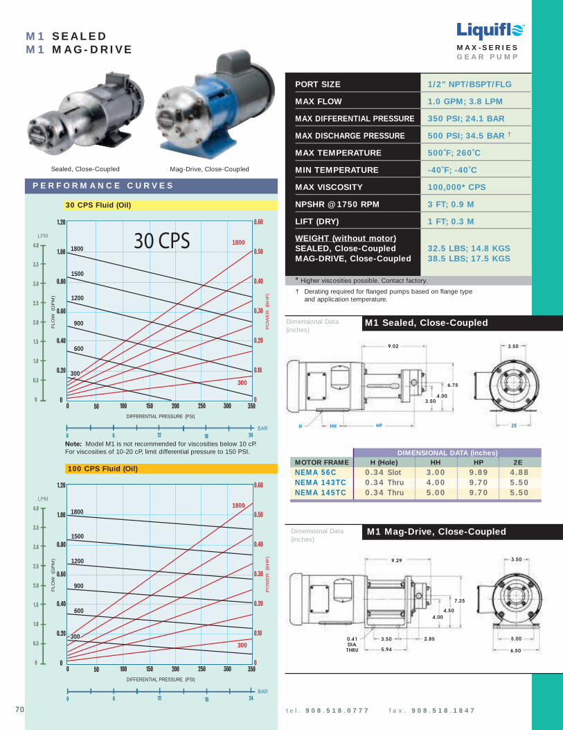
100 CPS Fluid (Oil)
P E R F O R M A N C E C U R V E S
t e l . 9 0 8 . 5 1 8 . 0 7 7 7 f a x . 9 0 8 . 5 1 8 . 1 8 4 7
M 1 S E A L E DM 1 M A G - D R I VE
PORT SIZE 1/2” NPT/BSPT/FLG
MAX FLOW 1.0 GPM; 3.8 LPM
MAX DIFFERENTIAL PRESSURE 350 PSI; 24.1 BAR
MAX DISCHARGE PRESSURE 500 PSI; 34.5 BAR †
MAX TEMPERATURE 500˚F; 260˚C
MIN TEMPERATURE -40˚F; -40˚C
MAX VISCOSITY 100,000* CPS
NPSHR @ 1750 RPM 3 FT; 0.9 M
LIFT (DRY) 1 FT; 0.3 M
WEIGHT (without motor)SEALED, Close-Coupled 32.5 LBS; 14.8 KGSMAG-DRIVE, Close-Coupled 38.5 LBS; 17.5 KGS
TM
M A X - S E R I E SG E A R P U M P
* Higher viscosities possible. Contact factory.
0 6 12 18
BAR24
DIFFERENTIAL PRESSURE (PSI)
1.20
1.00
0.80
0.60
0.40
0.20
020015010050 3500
1500
1200
900
PO
WE
R
(BH
P)
FL
OW
(G
PM
)
300
1800
600
0.60
0.50
0.40
0.30
0.20
0.10
0
1800
300250
LPM
4.0
3.5
3.0
2.5
2.0
1.5
1.0
0.5
0
300
70
M1 Mag-Drive, Close-CoupledDimensional Data(inches)
H
3.50
2E
4.003.50
HH
9.02
6.75
3.50
5.00
4.50
4.00
9.29
7.25
0.41DIA.
THRU
3.50
5.94
2.85
6.50
HP
Dimensional Data(inches)
M1 Sealed, Close-Coupled
† Derating required for flanged pumps based on flange type and application temperature.
Mag-Drive, Close-CoupledSealed, Close-Coupled
DIMENSIONAL DATA (inches)MOTOR FRAME H (Hole) HH HP 2ENEM A 56C 0 .34 Slot 3 .00 9 .89 4 .88NEM A 143TC 0 .34 Thru 4 .00 9 .70 5 .50NEM A 145TC 0 .34 Thru 5 .00 9 .70 5 .50
30 CPS Fluid (Oil)
DIFFERENTIAL PRESSURE (PSI)
1.20
1.00
0.80
0.60
0.40
0.20
020015010050 3500
1500
1200
900
PO
WE
R
(BH
P)
FL
OW
(G
PM
)
300
1800
600
0.60
0.50
0.40
0.30
0.20
0.10
0
1800
300250
LPM
4.0
3.5
3.0
2.5
2.0
1.5
1.0
0.5
0
300
0 6 12 18
BAR24
30 CPS
Note: Model M1 is not recommended for viscosities below 10 cP.For viscosities of 10-20 cP, limit differential pressure to 150 PSI.
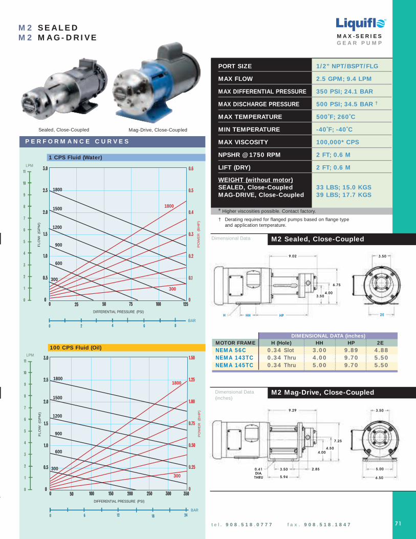
PORT SIZE 1/2” NPT/BSPT/FLG
MAX FLOW 2.5 GPM; 9.4 LPM
MAX DIFFERENTIAL PRESSURE 350 PSI; 24.1 BAR
MAX DISCHARGE PRESSURE 500 PSI; 34.5 BAR †
MAX TEMPERATURE 500˚F; 260˚C
MIN TEMPERATURE -40˚F; -40˚C
MAX VISCOSITY 100,000* CPS
NPSHR @ 1750 RPM 2 FT; 0.6 M
LIFT (DRY) 2 FT; 0.6 M
WEIGHT (without motor)SEALED, Close-Coupled 33 LBS; 15.0 KGSMAG-DRIVE, Close-Coupled 39 LBS; 17.7 KGS
* Higher viscosities possible. Contact factory.
P E R F O R M A N C E C U R V E S
DIFFERENTIAL PRESSURE (PSI)
3.0
2.5
2.0
1.5
1.0
0.5
0100755025 1250
1500
1200
900 PO
WE
R
(BH
P)
LPM
11
10
9
8
7
6
5
4
3
2
1
0
FL
OW
(G
PM
)
300
1800
600
300
0.6
0.5
0.4
0.3
0.2
0.1
0
1800
1 cP Fluid (Water)
0 2 4 6 8
BAR
M 2 S E A L E DM 2 M A G - D R I VE
TM
M A X - S E R I E SG E A R P U M P
t e l . 9 0 8 . 5 1 8 . 0 7 7 7 f a x . 9 0 8 . 5 1 8 . 1 8 4 7 71
Dimensional Data
M2 Mag-Drive, Close-CoupledDimensional Data(inches)
M2 Sealed, Close-Coupled
H
3.50
2E
4.003.50
HPHH
9.02
6.75
3.50
5.00
4.504.00
9.29
7.25
0.41DIA.
THRU
3.50
5.94
2.85
6.50
Mag-Drive, Close-CoupledSealed, Close-Coupled
1 CPS Fluid (Water)
DIFFERENTIAL PRESSURE (PSI)
3.0
2.5
2.0
1.5
1.0
0.5
020015010050 3500
1500
1200
900
PO
WE
R
(BH
P)
LPM
11
10
9
8
7
6
5
4
3
2
1
0
FL
OW
(G
PM
)
300
1800
0 6 12 18
BAR
600
300
1.50
1.25
1.00
0.75
0.50
0.25
0
1800
100 cP Fluid (Oil)
300250
24
100 CPS Fluid (Oil)
† Derating required for flanged pumps based on flange type and application temperature.
DIMENSIONAL DATA (inches)MOTOR FRAME H (Hole) HH HP 2ENEM A 56C 0 .34 Slot 3 .00 9 .89 4 .88NEM A 143TC 0 .34 Thru 4 .00 9 .70 5 .50NEM A 145TC 0 .34 Thru 5 .00 9 .70 5 .50

Mag-Drive, Close-CoupledSealed, Close-Coupled
PORT SIZE 1/2” NPT/BSPT/FLG
MAX FLOW 3.5 GPM; 13.1 LPM
MAX DIFFERENTIAL PRESSURE 350 PSI; 24.1 BAR
MAX DISCHARGE PRESSURE 500 PSI; 34.5 BAR †
MAX TEMPERATURE 500˚F; 260˚C
MIN TEMPERATURE -40˚F; -40˚C
MAX VISCOSITY 100,000* CPS
NPSHR @ 1750 RPM 2 FT; 0.6 M
LIFT (DRY) 4 FT; 1.2 M
WEIGHT (without motor)SEALED, Close-Coupled 33.5 LBS; 15.2 KGSMAG-DRIVE, Close-Coupled 39.5 LBS; 17.9 KGS
* Higher viscosities possible. Contact factory.
P E R F O R M A N C E C U R V E S
DIFFERENTIAL PRESSURE (PSI)
3.5
3.0
2.5
2.0
1.5
1.0
0.5
0100755025 1250
PO
WE
R
(BH
P)
FL
OW
(G
PM
)
300
1800
0 2 4 6 8
BAR
0.7
0.6
0.5
0.4
0.3
0.2
0.1
0
1 cP Fluid (Water)
1500
600
300
1800
900
1200
LPM
14
13
12
11
10
9
8
7
6
5
4
3
2
1
0
t e l . 9 0 8 . 5 1 8 . 0 7 7 7 f a x . 9 0 8 . 5 1 8 . 1 8 4 7
M 3 S E A L E DM 3 M A G - D R I VE
TM
M A X - S E R I E SG E A R P U M P
M3 Mag-Drive, Close-CoupledDimensional Data(inches)
H
3.50
2E
4.003.50
HH
9.02
6.75
3.50
5.00
4.504.00
9.29
7.25
0.41DIA.
THRU
3.50
5.94
2.85
6.50
HP
1 CPS Fluid (Water)
DIFFERENTIAL PRESSURE (PSI)
20015010050 3500
PO
WE
R
(BH
P)
FL
OW
(G
PM
)
300
1800
0 6 12 18
BAR
2.1
1.8
1.5
1.2
0.9
0.6
0.3
0
100 cP Fluid (Oil)
300250
24
3.5
3.0
2.5
2.0
1.5
1.0
0.5
0
LPM
14
13
12
11
10
9
8
7
6
5
4
3
2
1
0
1500
600
300
1800
900
1200
100 CPS Fluid (Oil)
Dimensional Data(inches)
M3 Sealed, Close-Coupled
† Derating required for flanged pumps based on flange type and application temperature.
72
DIMENSIONAL DATA (inches)MOTOR FRAME H (Hole) HH HP 2ENEM A 56C 0 .34 Slot 3 .00 9 .89 4 .88NEM A 143TC 0 .34 Thru 4 .00 9 .70 5 .50NEM A 145TC 0 .34 Thru 5 .00 9 .70 5 .50

Mag-Drive, Close-CoupledSealed, Close-Coupled
PORT SIZE 3/4” NPT/BSPT/FLG
MAX FLOW 5.2 GPM; 19.7 LPM
MAX DIFFERENTIAL PRESSURE 350 PSI; 24.1 BAR
MAX DISCHARGE PRESSURE 500 PSI; 34.5 BAR †
MAX TEMPERATURE 500˚F; 260˚C
MIN TEMPERATURE -40˚F; -40˚C
MAX VISCOSITY 100,000* CPS
NPSHR @ 1750 RPM 5 FT; 1.5 M
LIFT (DRY) 6 FT; 1.8 M
WEIGHT (without motor)SEALED, Close-Coupled 34 LBS; 15.5 KGSMAG-DRIVE, Close-Coupled 40 LBS; 18.2 KGS
* Higher viscosities possible. Contact factory.
DIFFERENTIAL PRESSURE (PSI)
5.5
5.0
4.5
4.0
3.5
3.0
2.5
2.0
1.5
1.0
0.5
0100755025 1250
PO
WE
R (B
HP
)
FL
OW
(G
PM
)
300
1800
0 2 4 6 8
BAR
1.1
1.0
0.9
0.8
0.7
0.6
0.5
0.4
0.3
0.2
0.1
0
1 cP Fluid (Water)
1500
600
300
1800
900
1200
LPM
22
20
18
16
14
12
10
8
6
4
2
0
1 CPS Fluid (Water)
P E R F O R M A N C E C U R V E S
5.5
5.0
4.5
4.0
3.5
3.0
2.5
2.0
1.5
1.0
0.5
0
PO
WE
R
(BH
P)
300
1800
2.75
2.50
2.25
2.00
1.75
1.50
1.25
1.00
0.75
0.50
0.25
0
1500
600
300
1800
900
1200
DIFFERENTIAL PRESSURE (PSI)
20015010050 3500
FL
OW
(G
PM
)
0 6 12 18
BAR
100 cP Fluid (Oil)
300250
24
LPM
22
20
18
16
14
12
10
8
6
4
2
0
M 4 S E A L E DM 4 M A G - D R I VE M A X - S E R I E S
G E A R P U M P
t e l . 9 0 8 . 5 1 8 . 0 7 7 7 f a x . 9 0 8 . 5 1 8 . 1 8 4 7 73
100 CPS Fluid (Oil)
Dimensional Data(inches)
M4 Mag-Drive, Close-CoupledDimensional Data(inches)
M4 Sealed, Close-Coupled
H
3.50
2E
4.003.50
HPHH
9.45
6.75
3.50
5.00
4.50
9.73
7.25
0.41DIA.
THRU
3.50
5.94
3.07
6.50
4.00
† Derating required for flanged pumps based on flange type and application temperature.
DIMENSIONAL DATA (inches)MOTOR FRAME H (Hole) HH HP 2ENEM A 56C 0 .34 Slot 3 .00 10 .10 4 .88NEM A 143TC 0 .34 Thru 4 .00 9 .91 5 .50NEM A 145TC 0 .34 Thru 5 .00 9 .91 5 .50
TM

PORT SIZE 3/4” NPT/BSPT/FLG
MAX FLOW 8.8 GPM; 33.5 LPM
MAX DIFFERENTIAL PRESSURE 350 PSI; 24.1 BAR
MAX DISCHARGE PRESSURE 500 PSI; 34.5 BAR †
MAX TEMPERATURE 500˚F; 260˚C
MIN TEMPERATURE -40˚F; -40˚C
MAX VISCOSITY 100,000* CPS
NPSHR @ 1750 RPM 5 FT; 1.5 M
LIFT (DRY) 6 FT; 1.8 M
WEIGHT (without motor)SEALED, Close-Coupled 42 LBS; 19.1 KGSMAG-DRIVE, Close-Coupled 42 LBS; 19.1 KGS
* Higher viscosities possible. Contact factory.
DIFFERENTIAL PRESSURE (PSI)
9
8
7
6
5
4
3
2
1
0100755025 1250
PO
WE
R
(BH
P)
FL
OW
(G
PM
)
300
1800
0 2 4 6 8
BAR
1.8
1.6
1.4
1.2
1.0
0.8
0.6
0.4
0.2
0
1 cP Fluid (Water)
1500
600
300
1800
900
1200
LPM
36
32
28
24
20
16
12
8
4
0
1 CPS Fluid (Water)
P E R F O R M A N C E C U R V E S
9
8
7
6
5
4
3
2
1
0
300
1800
4.5
4.0
3.5
3.0
2.5
2.0
1.5
1.0
0.5
0
1500
600
300
1800
900
1200
DIFFERENTIAL PRESSURE (PSI)
20015010050 3500
FL
OW
(G
PM
)
0 6 12 18
BAR
100 cP Fluid (Oil)
300250
24
LPM
36
32
28
24
20
16
12
8
4
0
PO
WE
R
(BH
P)
74 t e l . 9 0 8 . 5 1 8 . 0 7 7 7 f a x . 9 0 8 . 5 1 8 . 1 8 4 7
M 5 S E A L E DM 5 M A G - D R I VE
TM
M A X - S E R I E SG E A R P U M P
100 CPS Fluid (Oil)
Dimensional Data(inches)
M5 Mag-Drive, Close-CoupledDimensional Data(inches)
M5 Sealed, Close-Coupled
0.41DIA.
THRU
4.04
5.00
4.75
5.94
3.51
10.83
7.25
4.04
5.00
4.754.00
11.26
7.25
0.41DIA.
THRU
3.50
5.94
3.94
6.50
3.50
4.00
6.50
Sealed or Mag-Drive, Close-Coupled
† Derating required for flanged pumps based on flange type and application temperature.

PORT SIZE 1” NPT/BSPT/FLG
MAX FLOW 12.2 GPM; 46 LPM
MAX DIFFERENTIAL PRESSURE 350 PSI; 24.1 BAR
MAX DISCHARGE PRESSURE 500 PSI; 34.5 BAR †
MAX TEMPERATURE 500˚F; 260˚C
MIN TEMPERATURE -40˚F; -40˚C
MAX VISCOSITY 100,000* CPS
NPSHR @ 1750 RPM 5 FT; 1.5 M
LIFT (DRY) 7 FT; 2.1 M
WEIGHT (without motor)SEALED, Close-Coupled 54 LBS; 24.5 KGSMAG-DRIVE, Close-Coupled 54 LBS; 24.5 KGS
* Higher viscosities possible. Contact factory.
DIFFERENTIAL PRESSURE (PSI)
13
12
11
10
9
8
7
6
5
4
3
2
1
0100755025 1250
PO
WE
R (B
HP
)
FL
OW
(G
PM
)
300
1800
0 2 4 6 8
BAR
1.95
1.80
1.65
1.50
1.35
1.20
1.05
0.90
0.75
0.60
0.45
0.30
0.15
0
1 cP Fluid (Water)
1500
600
300
1800
900
1200
LPM
50
45
40
35
30
25
20
15
10
5
0
1 CPS Fluid (Water)
P E R F O R M A N C E C U R V E S
13
12
11
10
9
8
7
6
5
4
3
2
1
0
PO
WE
R
(BH
P)
300
1800
6.5
6.0
5.5
5.0
4.5
4.0
3.5
3.0
2.5
2.0
1.5
1.0
0.5
0
1500
600
300
1800
900
1200
DIFFERENTIAL PRESSURE (PSI)
20015010050 3500
FL
OW
(G
PM
)
0 6 12 18
BAR
100 cP Fluid (Oil)
300250
24
LPM
50
45
40
35
30
25
20
15
10
5
0
M 6 S E A L E DM 6 M A G - D R I VE M A X - S E R I E S
G E A R P U M P
t e l . 9 0 8 . 5 1 8 . 0 7 7 7 f a x . 9 0 8 . 5 1 8 . 1 8 4 7 75
100 CPS Fluid (Oil)
Dimensional Data(inches)
M6 Mag-Drive, Close-CoupledDimensional Data(inches)
M6 Sealed, Close-Coupled
0.41DIA.
THRU
4.04
5.00
4.754.00
5.94
3.70
11.20
7.25
4.04
5.00
4.754.00
11.63
7.25
0.41DIA.
THRU
3.50
5.94
4.13
6.50
6.50
3.50
Sealed or Mag-Drive, Close-Coupled
† Derating required for flanged pumps based on flange type and application temperature.
TM
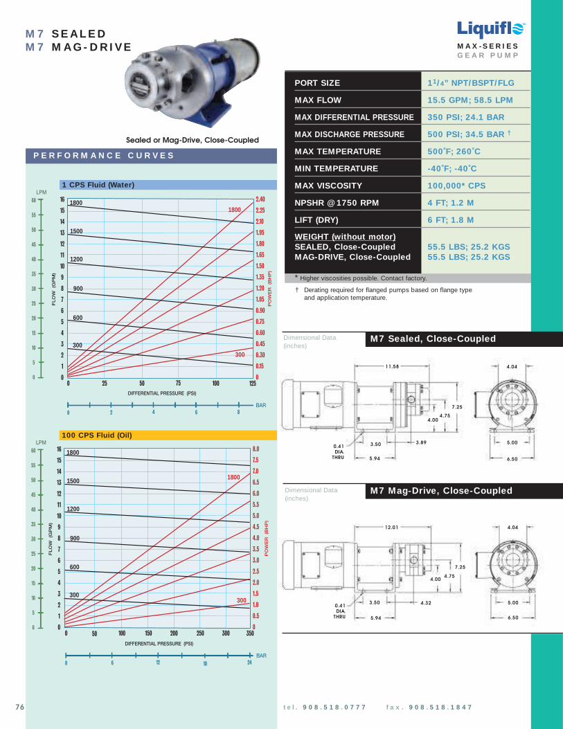
PORT SIZE 11/ 4” NPT/BSPT/FLG
MAX FLOW 15.5 GPM; 58.5 LPM
MAX DIFFERENTIAL PRESSURE 350 PSI; 24.1 BAR
MAX DISCHARGE PRESSURE 500 PSI; 34.5 BAR †
MAX TEMPERATURE 500˚F; 260˚C
MIN TEMPERATURE -40˚F; -40˚C
MAX VISCOSITY 100,000* CPS
NPSHR @ 1750 RPM 4 FT; 1.2 M
LIFT (DRY) 6 FT; 1.8 M
WEIGHT (without motor)SEALED, Close-Coupled 55.5 LBS; 25.2 KGSMAG-DRIVE, Close-Coupled 55.5 LBS; 25.2 KGS
* Higher viscosities possible. Contact factory.
DIFFERENTIAL PRESSURE (PSI)
16
15
14
13
12
11
10
9
8
7
6
5
4
3
2
1
0100755025 1250
PO
WE
R (B
HP
)
FL
OW
(G
PM
)
300
1800
0 2 4 6 8
BAR
2.40
2.25
2.10
1.95
1.80
1.65
1.50
1.35
1.20
1.05
0.90
0.75
0.60
0.45
0.30
0.15
0
1 cP Fluid (Water)
1500
600
300
1800
900
1200
LPM
60
55
50
45
40
35
30
25
20
15
10
5
0
1 CPS Fluid (Water)
P E R F O R M A N C E C U R V E S
16
15
14
13
12
11
10
9
8
7
6
5
4
3
2
1
0
PO
WE
R
(BH
P)
FL
OW
(G
PM
)
300
1800
8.0
7.5
7.0
6.5
6.0
5.5
5.0
4.5
4.0
3.5
3.0
2.5
2.0
1.5
1.0
0.5
0
1500
600
300
1800
900
1200
DIFFERENTIAL PRESSURE (PSI)
20015010050 3500
0 6 12 18
BAR
100 cP Fluid (Oil)
300250
24
LPM
60
55
50
45
40
35
30
25
20
15
10
5
0
76 t e l . 9 0 8 . 5 1 8 . 0 7 7 7 f a x . 9 0 8 . 5 1 8 . 1 8 4 7
M 7 S E A L E DM 7 M A G - D R I VE
TM
M A X - S E R I E SG E A R P U M P
100 CPS Fluid (Oil)
Dimensional Data(inches)
M7 Mag-Drive, Close-CoupledDimensional Data(inches)
M7 Sealed, Close-Coupled
0.41DIA.
THRU
4.04
5.00
4.75
5.94
3.89
11.58
7.25
4.04
5.00
4.754.00
12.01
7.25
0.41DIA.
THRU
3.50
5.94
4.32
6.50
3.50
4.00
6.50
Sealed or Mag-Drive, Close-Coupled
† Derating required for flanged pumps based on flange type and application temperature.

PORT SIZE 11/ 2” NPT/BSPT/FLG
MAX FLOW 20 GPM; 75 LPM
MAX DIFFERENTIAL PRESSURE 350 PSI; 24.1 BAR
MAX DISCHARGE PRESSURE 500 PSI; 34.5 BAR †
MAX TEMPERATURE 500˚F; 260˚C
MIN TEMPERATURE -40˚F; -40˚C
MAX VISCOSITY 100,000* CPS
NPSHR @ 1750 RPM 3 FT; 0.9 M
LIFT (DRY) 14 FT; 4.3 M
WEIGHT (without motor)SEALED, Close-Coupled 56 LBS; 25.4 KGSMAG-DRIVE, Close-Coupled 56 LBS; 25.4 KGS
* Higher viscosities possible. Contact factory.
DIFFERENTIAL PRESSURE (PSI)
100755025 1250
PO
WE
R (B
HP
)
FL
OW
(G
PM
)
300
1800
0 2 4 6 8
BAR
3.0
2.7
2.4
2.1
1.8
1.5
1.2
0.9
0.6
0.3
0
1 cP Fluid (Water)
1500
600
300
1800
900
1200
LPM
75
70
65
60
55
50
45
40
35
30
25
20
15
10
5
0
20
18
16
14
12
10
8
6
4
2
0
1 CPS Fluid (Water)
P E R F O R M A N C E C U R V E S
Sealed or Mag-Drive, Close-Coupled
M 8 S E A L E DM 8 M A G - D R I VE M A X - S E R I E S
G E A R P U M P
t e l . 9 0 8 . 5 1 8 . 0 7 7 7 f a x . 9 0 8 . 5 1 8 . 1 8 4 7 77
Dimensional Data(inches)
M8 Mag-Drive, Close-Coupled Dimensional Data(inches)
M8 Sealed, Close-Coupled
0.41DIA.
THRU
4.04
5.00
4.00
5.94
4.14
12.08
7.25
4.04
5.00
4.754.00
12.51
7.25
0.41DIA.
THRU
3.50
5.94
4.57
6.50
6.50
3.50
20
18
16
14
12
10
8
6
4
2
0
PO
WE
R
(BH
P)
300
1800
10
9
8
7
6
5
4
3
2
1
0
1500
600
300
1800
900
1200
FL
OW
(G
PM
)
DIFFERENTIAL PRESSURE (PSI)
20015010050 3500
0 6 12 18
BAR
100 cP Fluid (Oil)
300250
24
LPM
75
70
65
60
55
50
45
40
35
30
25
20
15
10
5
0
100 CPS Fluid (Oil)
† Derating required for flanged pumps based on flange type and application temperature.
4.75
TM

78 t e l . 9 0 8 . 5 1 8 . 0 7 7 7 f a x . 9 0 8 . 5 1 8 . 1 8 4 7 w w w . l i q u i f l o . c o m
FEATURESCentry® Models 621 and 622 are available with closed impellers as standard. Closedimpellers eliminate axial loads and extendthe life of the motor bearings when thepump is close-coupled to the motor. Forclose-coupled sealed pumps, closedimpellers simplify the axial positioning of the impeller.
MODELS AVAILABLE
Liquiflo's Centry ® line of Centrifuga l pumpsare ava ilable in 316 SS or Alloy-C w ith eitherPack ing, Single M echanica l Sea l, Double M echanica l Sea l or M ag-Drive configura tion.
0 25 50 75 100 125 150 175
100
75
50
0
25
FLOW RATE (GPM )
HEA
D (
Fee
t)
M odel�621
125
M odel�622
M odel�620
C E N T RY ® S U B - A N S I C E N T R I F U G A L P U M P S
L I Q U I F L O C H E M I C A L P R O C E S S I N G P U M P S
MODEL SIZE* (inches) MAX FLOW MAX HEAD
620 1 x 3/ 4 x 3 3/ 4 45 GPM 65 ft
621 1 1/ 4 x 1 x 5 90 GPM 100 ft
622 2 x 1 1/ 2 x 5 160 GPM 95 ft
* Suction Port Size x Discharge Port Size x Impeller Diameter Single Mechanical Seals:
Single mechanical seals are the mosteconomical type of seal to use whenleakage is not desired. When properlyinstalled and maintained, these seals willgenerally give years of trouble-free service.
Double Mechanical Seals:
Double Mechanical seals are also available for the Liquiflo Centry® Series centrifugalpumps. This seal configuration relies on abarrier lubrication system to cool andlubricate the seal faces.
Magnetically-Coupled Pumps:
These offer a simple and cost-effectivesolution to sealing toxic, noxious, crystallizingor most other fluids that present problems forsingle seals and would therefore require useof a double mechanical seal. Magnetically-coupled pumps eliminate the need for cooling loops that are required for doublemechanical seals.
CUSTOMIZATIONContact factory.
Centry® Model 621/622 Sealed Pumpshown Close-Coupled to motor.
Centry® Model 621/622 Mag-Drive Pump shownClose-Coupled to motor.
CENTRY-SERIESCENTRIFUGAL PUMPS
The Centry ® Series are Sealed and Magnetically-Coupled (MC)Centrifugal pumps engineered and manufactured for the user with increased needs for equipment reliability. These pumpsare specifically designed to handle the lower flow applicationsthat create maintenance problems for standard ANSI pumpsoperating at less than BEP. The Centry Series pumps can handleflows up to 160 GPM and heads up to 100 ft. They are availablein 316 Stainless Steel or Alloy-C constructions, and with threadedor flanged port configurations.
TM

L I Q U I F L O C H E M I C A L P R O C E S S I N G P U M P S
Centry® Model 620Mag-Drive Pump shownClose-Coupled to motor.
SEALED PUMP
MAG-DRIVE PUMP
MOTOR
MOTOR
Mechanically Sealed Pumps:• Compact close-coupled design or
long-coupled mounting
• Back pullout design to simplify maintenance
• Type 9 or Type 21 seals are available
• Several choices for seal materials to meet the requirements of the application
• Single or Double mechanical seal configurations are available
Mag-Drive Pumps:• Double support sleeve bearings are available
in Carbon or Silicon Carbide to extend the working life of the pump
• Optional hard Ceramic coated or Tungsten Carbide coated shafts are available for abrasive or thin fluids
• Available in compact close-coupled or Power Frame design, depending on model
Features of Sealed and SeallessCentry ® Pumps
Centry® Model 621 or Model 622
Centry® Model 621 or Model 622
Centry® Model 620 Sealed Pumpshown Close-Coupled to motor.
t e l . 9 0 8 . 5 1 8 . 0 7 7 7 f a x . 9 0 8 . 5 1 8 . 1 8 4 7 w w w . l i q u i f l o . c o m 79
CENTRY-SERIESCENTRIFUGAL PUMPS
TM

PUMP MODEL CODING
620 F S 2 0 0 0
Pump Model 620 Model 620
Impeller Diameter F Full- 3.75”
Basic Material S 316 SS
Seal Configuration 2 Sing. Int. Mech.
Motor Frame 0 NEMA 56C
O-Rings/Gaskets 0 Teflon
Impeller Trim 0 No Trim
1 2 3 4 5 6 7
1
2
3
4
5
6
7
Pos. Description Selection
EXAM PLE:620FS2000, designates a CentryModel 620 Sealed Centrifugal Pump.
Liquiflo’s Model Code describesboth the pump’s size and materialsselected. This model code is required for the future identification of yourpump when reordering either a pump or replacement parts. Model code ispermanently stamped into pumphousing.
n Available
U Not Available
CF Contact Factory
80 t e l . 9 0 8 . 5 1 8 . 0 7 7 7 f a x . 9 0 8 . 5 1 8 . 1 8 4 7 w w w . l i q u i f l o . c o m
TM
CENTRY-SERIESCENTRIFUGAL PUMPS
620 621 622
F = Full – 3.75” / 5.0” / 5.0” n n nR = Reduced (See Pos. 7) n n n
S = 316 SS NPT n n nL = 316 SS ANSI 150# RF Flanges n n nH = Alloy-C NPT n U UC = Alloy-C ANSI 150# RF Flanges n U U
2 = Single Internal Carbon/SiC n n n3 = Single Internal Teflon/SiC n U U4 = Double Carbon/SiC n U U5 = Lantern Ring Teflon Packing n U U7 = Lantern Ring Graphoil Packing n U U
0 = NEMA 56C/56HC (Close-Coupled) n n n1 = NEMA 143TC/145TC (Close-Coupled) n n n5 = NEMA 182TC/184TC (Close-Coupled) U n nP = Power Frame n n n
0 = Teflon n n nV = Viton n n nG = Graphoil n n n
0 = No Trim (Pos. 2 = F) n n n1 = 3.50” / 4.5” / 4.5” (Pos. 2 = R) n n n2 = 3.25” / 4.0” / 4.0” (Pos. 2 = R) n n n3 = 3.00” / 3.5” / 3.5” (Pos. 2 = R) n n n4 = 2.75” / 3.0” / 3.0” (Pos. 2 = R) n n n
3PositionHousing Material
& Port Type
4PositionSeal
Configuration
5PositionMotor Frame
6PositionO-rings/Gaskets
7PositionImpeller Trim
(Standard)
SEALED Pump Model1PositionModel
SEALED Pump Sample Model No.
Position No.
620 S 2 0 0 0
1 2 3 4 5 6 7
2PositionImpeller Diameter
F
620 621 622
F = Full – 3.75” / 5.0” / 5.0” n n nR = Reduced (See Pos. 10) n n n
S = 316 SS NPT n n nL = 316 SS ANSI 150# RF Flanges n n nH = Alloy-C NPT n U UC = Alloy-C ANSI 150# RF Flanges n U U
2 = Carbon U U U3 = Teflon n CF CFB = Silicon Carbide n n nE = Carbon 60 n n n
2 = Carbon U U U3 = Teflon n CF CFB = Silicon Carbide n n nE = Carbon 60 n U U
0 = NEMA 56C/56HC (0.625”) n n n1 = NEMA 143TC/145TC (0.875”) n n n2 = IEC 71 – B5 (14 mm) n n n3 = IEC 80 – B5 (19 mm) n n n4 = IEC 90 – B5 (24 mm) n n n5 = NEMA 182TC/184TC (1.125”) U n n
1 = Chrome Oxide n n n2 = Tungsten Carbide n n n
0 = Teflon n n nV = Viton n n nG = Graphoil n n n
D = (MCD) 33 in-lbs n U UF = (MCF) 120 in-lbs n n nW = (MCW) 200 in-lbs U n n
0 = No Trim (Pos. 2 = F) n n n1 = 3.50” / 4.5” / 4.5” (Pos. 2 = R) n n n2 = 3.25” / 4.0” / 4.0” (Pos. 2 = R) n n n3 = 3.00” / 3.5” / 3.5” (Pos. 2 = R) n n n4 = 2.75” / 3.0” / 3.0” (Pos. 2 = R) n n n
3PositionHousing Material
& Port Type
4PositionBearings
5PositionThrust Washers
6PositionMotor Frame
(Outer Magnet Bore)
7PositionShaft Coating
MAG-DRIVE Pump Model1PositionModel
MAG-DRIVE Pump Sample Model No.
Position No.
622 S E B 1 2 V F 2
1 2 3 4 5 6 7 8 9 10
2PositionImpeller Diameter
R
8PositionO-Rings/Gaskets
9PositionMagnetic Coupling
10PositionImpeller Trim
(Standard)
622 R S E B 1 2 V F 2
Pump Model 622 Model 622
Impeller Diameter R Reduced
Basic Material S 316 SS
Bearings E Carbon 60
Thrust Washers B SiC
Motor Frame 1 143TC/145TC
Shaft Coating 2 TC-coated
O-Rings/Gaskets V Viton
Magnetic Coupling F MCF, 120 in-lbs
Impeller Trim 2 4.0” Dia.
1 2 3 4 5 6 7 8 9 10
1
2
3
4
5
6
7
8
9
10
Pos. Description Code Selection
EXAM PLE:622RSEB12VF2 , designates a Centry Model 622 Mag-drive Centrifugal Pump.

t e l . 9 0 8 . 5 1 8 . 0 7 7 7 f a x . 9 0 8 . 5 1 8 . 1 8 4 7 w w w . l i q u i f l o . c o m
CENTRY-SERIESCENTRIFUGAL PUMPS
81
Port Connections: Suction 1.00” NPT/FLGDischarge 0.75” NPT/FLG
Impeller Diameter 3.75”
Impeller Trims (standard) 3.50”, 3.25”, 3.00” & 2.75”
Max Flow Rate 45 GPM
Max Total Head 65 ft
Max Discharge Pressure 300 PSI
Max Temperature 500 °F
Min Temperature -40 °F
NPSHR @ 3500 RPM & BEP 7.5 ft
NPSHR @ 1750 RPM & BEP 2.0 ft
Pump Weights: (less motor) NPT FLGSealed, Single Int. Mech. 16 lbs 20 lbsSealed, Packing & Dbl. Mech. 26 lbs 30 lbsMag-Drive 30 lbs 34 lbs
CENTRY M ODEL 620 TYPICAL PERFORM ANCE CHARACTERISTICS
6 2 0 S E A L E D 6 2 0 - M C M A G - D R I VE
6 2 0 SEA LED Dimensional data - inches
6 2 0 M A G - D RI V E Dimensional data - inches
1.00”SUCTION
MOTORLc
2.50
6.50
7.25
5.94
3.50
1.00”SUCTION
2.500.41DIA. THRU
Motor
2.25
8.87 6.50
4.14
Head (
Feet)
20
18
16
14
12
10
8
6
4
2
0
3.75
3.50
3.25 3.00
2.75
Eff
icie
ncy
Head (
Feet)
80
70
60
50
40
30
20
10
0
3.75
3.50 3.25
3.00 2.75
Model 620 1 x 0.75 x 3.75 1750 RPM Model 620 1 x 0.75 x 3.75 3500 RPM50
45
40
35
30
25
20
15
10
5
0
Eff
icie
ncy
50
45
40
35
30
25
20
15
10
5
0
30105 400 50252015 45350 15105 20 25
Flow (GPM)
0.20
0.15
0.10
0.05
0.0
3.75
2.75
5
4
3
2
1
0
3.75
BH
PN
PSH
R (
Feet)
Flow (GPM)
1.5
1.0
0.5
0.0
3.75
2.75
18
15
12
9
6
3
0
3.75
BH
PN
PSH
R (
Feet)
3.75 3.75
21 34
4244
44
42
38
34
28
21 34
4244
44
42
38
34
28
7.50
2.75
6.54
5.29 1.25 0.75”DISCHARGE
0.75”DISCHARGE
7.62
4.000.38
2.75
1.25 2.25
Motor
TM
Sealed, Close-Coupled Mag-drive, Close-Coupled

82 t e l . 9 0 8 . 5 1 8 . 0 7 7 7 f a x . 9 0 8 . 5 1 8 . 1 8 4 7 w w w . l i q u i f l o . c o m
CENTRY-SERIESCENTRIFUGAL PUMPS
Port Connections: Suction 1.25” NPT/FLGDischarge 1.00” NPT/FLG
Impeller Diameter 5.0”
Impeller Trims (standard) 4.5”, 4.0”, 3.5” & 3.0”
Max Flow Rate 90 GPM
Max Total Head 100 ft
Max Discharge Pressure 300 PSI
Max Temperature 500 °F
Min Temperature -40 °F
NPSHR @ 3500 RPM & BEP 15 ft
NPSHR @ 1750 RPM & BEP 3.7 ft
Pump Weights: (less motor) NPT FLGSealed, Single Int. Mech. 17 lbs 23 lbsMag-Drive 42 lbs 48 lbs
Sealed, Close-Coupled Mag-drive, Close-Coupled
6 2 1 S E A L E D 6 2 1 - M C M A G - D R I VE
6 2 1 SEA LED Dimensional data - inches
6 2 1 M A G - D RI V E Dimensional data - inches
1.25” SUCTION1 .32
MOTORLc
2.50
6.50
4.00
5.94
3.50
1.25” SUCTION1.00” DISCHARGE
2.500.41
DIA. THRU
Motor
1.00” DISCHARGE 2 .75
3 .50
5 .83
9.33
3.50
2 .751 .32
4.58
CENTRY M ODEL 621 TYPICAL PERFORM ANCE CHARACTERISTICS
Head (
Feet)
30
25
20
15
10
5
0
60
50
40
30
20
10
0
Head (
Feet)
Model 621 1.25 x 1 x 5 1750 RPM Model 621 1.25 x 1 x 5 3500 RPM
Eff
icie
ncy
Eff
icie
ncy
60
50
40
30
20
10
0
5.0
4.5
4.0
3.5 3.0
5.0
14 26 36
44 49
50
48
42
34
5.0
4.5
4.0
3.5 3.0
5.0
14 26 36
44 49
50
48
42
34
120
100
80
60
40
20
0
30105 400 50252015 4535 602010 800 100504030 9070
Flow (GPM)
0.4
0.3
0.2
0.1
0.0
5.0
3.0
BH
PN
PSH
R (
Feet)
Flow (GPM)
3
2
1
0
5.0
3.0
BH
PN
PSH
R (
Feet)
6
5
4
3
2
1
0
5.0
25
20
15
10
5
0
5.0
TM

83t e l . 9 0 8 . 5 1 8 . 0 7 7 7 f a x . 9 0 8 . 5 1 8 . 1 8 4 7 w w w . l i q u i f l o . c o m
CENTRY-SERIESCENTRIFUGAL PUMPS
Port Connections: Suction 2.0” NPT/FLGDischarge 1.5” NPT/FLG
Impeller Diameter 5.0”
Impeller Trims (standard) 4.5”, 4.0”, 3.5” & 3.0”
Max Flow Rate 160 GPM
Max Total Head 95 ft
Max Discharge Pressure 300 PSI
Max Temperature 500 °F
Min Temperature -40 °F
NPSHR @ 3500 RPM & BEP 13 ft
NPSHR @ 1750 RPM & BEP 3.2 ft
Pump Weights: (less motor) NPT FLGSealed, Single Int. Mech. 22 lbs 30 lbsMag-Drive 48 lbs 56 lbs
Sealed, Close-Coupled Mag-drive, Close-Coupled
6 2 2 S E A L E D 6 2 2 - M C M A G - D R I VE
6 2 2 SEA LED Dimensional data - inches
6 2 2 M A G - D RI V E Dimensional data - inches
2.0” SUCTION2 .12
MOTORLc
2.50
6.50
4.00
5.94
3.50
2.0” SUCTION1.5” DISCHARGE
2.500.41
DIA. THRU
Motor
1.5” DISCHARGE 3 .12
3 .82
6 .70
10.20
3.82
3 .122 .12
5.45
CENTRY M ODEL 622 TYPICAL PERFORM ANCE CHARACTERISTICS
Head (
Feet)
30
25
20
15
10
5
0
502010 700 904030 8060
Model 622 2 x 1.5 x 5 1750 RPM Model 622 2 x 1.5 x 5 3500 RPM
Head (
Feet)
120
100
80
60
40
20
0
1004020 1400 1808060 160120
Flow (GPM)
0.6
0.5
0.4
0.3
0.2
0.1
0
5.0
3.0
5
4
3
2
1
0
5.0
BH
PN
PSH
R (
Feet)
Flow (GPM)
18
15
12
9
6
3
0
5.0
BH
PN
PSH
R (
Feet)
Eff
icie
ncy
5.0
4.5
4.0
3.5
3.0
70
60
50
40
30
20
10
0
18 34 4655
60
61
59
54
5.0
5.0
4.5
4.0
3.5
3.0
70
60
50
40
30
20
10
0
18 34 4655
60
61
59
54
5.0
5
4
3
2
1
0
5.0
3.0
Eff
icie
ncy
TM
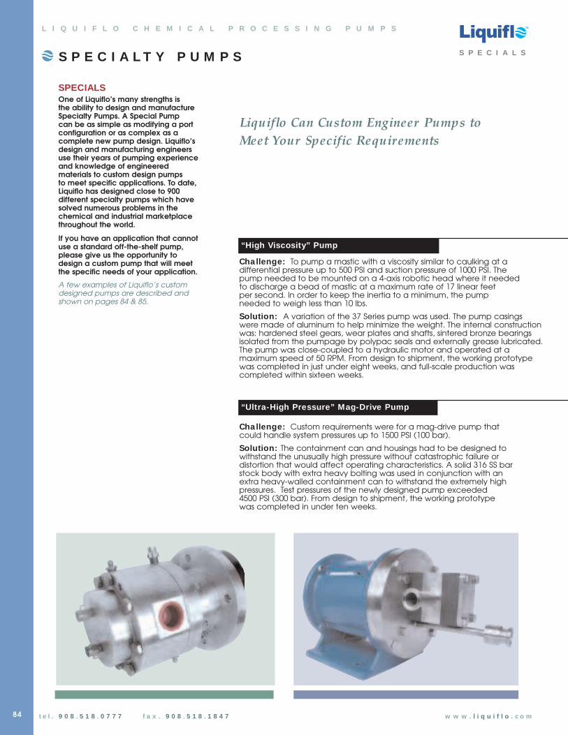
TM
t e l . 9 0 8 . 5 1 8 . 0 7 7 7 f a x . 9 0 8 . 5 1 8 . 1 8 4 7 w w w . l i q u i f l o . c o m
SPECIALSOne of Liquiflo’s many strengths is the ability to design and manufactureSpecialty Pumps. A Special Pump can be as simple as modifying a portconfiguration or as complex as acomplete new pump design. Liquiflo’sdesign and manufacturing engineersuse their years of pumping experienceand knowledge of engineeredmaterials to custom design pumps to meet specific applications. To date,Liquiflo has designed close to 900different specialty pumps which havesolved numerous problems in thechemical and industrial marketplacethroughout the world.
If you have an application that cannotuse a standard off-the-shelf pump,please give us the opportunity todesign a custom pump that will meetthe specific needs of your application.
A few examples of Liquiflo’s customdesigned pumps are described andshown on pages 84 & 85.
S P E C I A L T Y P U M P S S P E C I A L S
L I Q U I F L O C H E M I C A L P R O C E S S I N G P U M P S
“High Viscosity” Pump
Cha llenge: To pump a mastic with a viscosity similar to caulking at adifferential pressure up to 500 PSI and suction pressure of 1000 PSI. The pump needed to be mounted on a 4-axis robotic head where it needed to discharge a bead of mastic at a maximum rate of 17 linear feet per second. In order to keep the inertia to a minimum, the pump needed to weigh less than 10 lbs.
Solution: A variation of the 37 Series pump was used. The pump casings were made of aluminum to help minimize the weight. The internal construction was: hardened steel gears, wear plates and shafts, sintered bronze bearingsisolated from the pumpage by polypac seals and externally grease lubricated.The pump was close-coupled to a hydraulic motor and operated at amaximum speed of 50 RPM. From design to shipment, the working prototypewas completed in just under eight weeks, and full-scale production was completed within sixteen weeks.
“Ultra-High Pressure” Mag-Drive Pump
Cha llenge: Custom requirements were for a mag-drive pump thatcould handle system pressures up to 1500 PSI (100 bar).
Solution: The containment can and housings had to be designed towithstand the unusually high pressure without catastrophic failure ordistortion that would affect operating characteristics. A solid 316 SS barstock body with extra heavy bolting was used in conjunction with anextra heavy-walled containment can to withstand the extremely highpressures. Test pressures of the newly designed pump exceeded 4500 PSI (300 bar). From design to shipment, the working prototype was completed in under ten weeks.
Liquiflo Can Custom Engineer Pumps to
Meet Your Specific Requirements
84
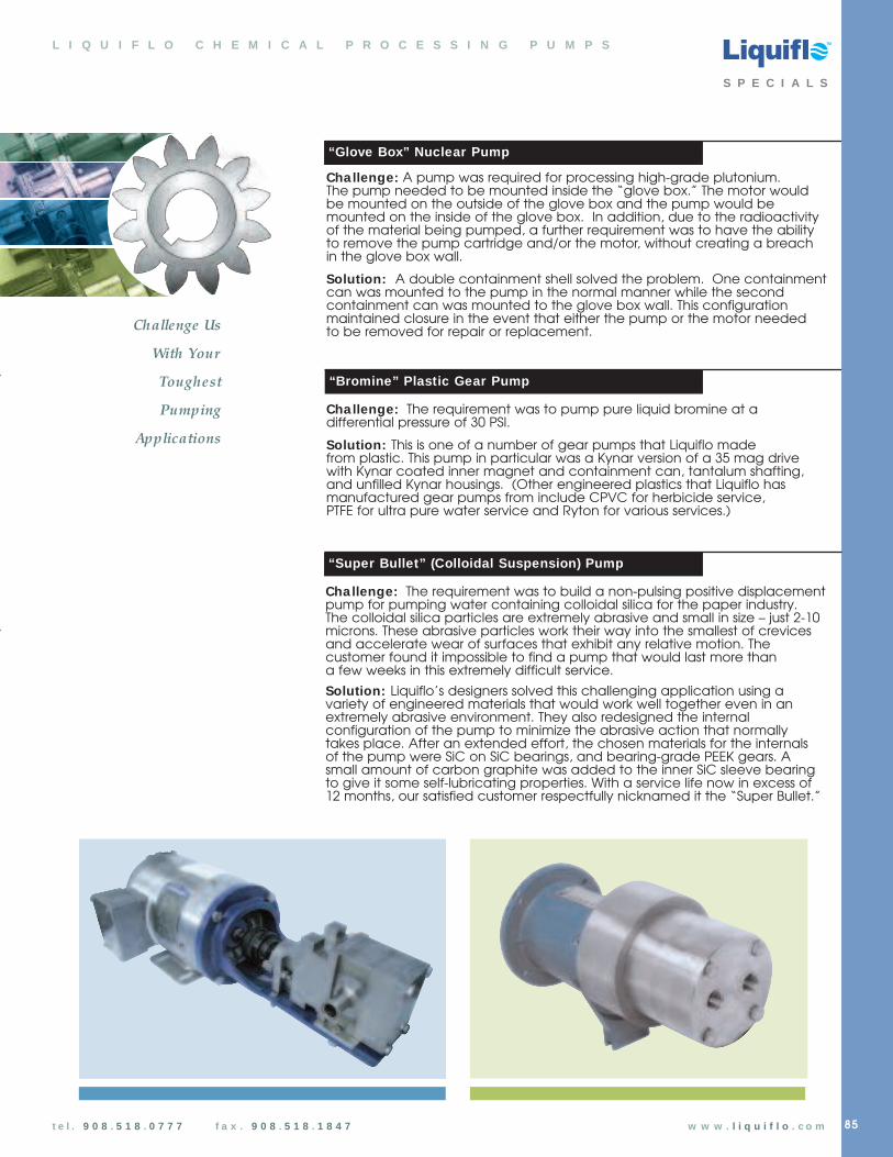
“Glove Box” Nuclear Pump
TM
t e l . 9 0 8 . 5 1 8 . 0 7 7 7 f a x . 9 0 8 . 5 1 8 . 1 8 4 7 w w w . l i q u i f l o . c o m
Cha llenge: A pump was required for processing high-grade plutonium.The pump needed to be mounted inside the “glove box.” The motor wouldbe mounted on the outside of the glove box and the pump would bemounted on the inside of the glove box. In addition, due to the radioactivityof the material being pumped, a further requirement was to have the abilityto remove the pump cartridge and/or the motor, without creating a breach in the glove box wall.
Solution: A double containment shell solved the problem. One containmentcan was mounted to the pump in the normal manner while the secondcontainment can was mounted to the glove box wall. This configurationmaintained closure in the event that either the pump or the motor needed to be removed for repair or replacement.
“Bromine” Plastic Gear Pump
Cha llenge: The requirement was to pump pure liquid bromine at adifferential pressure of 30 PSI.
Solution: This is one of a number of gear pumps that Liquiflo made from plastic. This pump in particular was a Kynar version of a 35 mag drivewith Kynar coated inner magnet and containment can, tantalum shafting,and unfilled Kynar housings. (Other engineered plastics that Liquiflo hasmanufactured gear pumps from include CPVC for herbicide service, PTFE for ultra pure water service and Ryton for various services.)
L I Q U I F L O C H E M I C A L P R O C E S S I N G P U M P S
85
“Super Bullet” (Colloidal Suspension) Pump
Cha llenge: The requirement was to build a non-pulsing positive displacement pump for pumping water containing colloidal silica for the paper industry. The colloidal silica particles are extremely abrasive and small in size – just 2-10microns. These abrasive particles work their way into the smallest of crevices and accelerate wear of surfaces that exhibit any relative motion. Thecustomer found it impossible to find a pump that would last more thana few weeks in this extremely difficult service.
Solution: Liquiflo’s designers solved this challenging application using avariety of engineered materials that would work well together even in anextremely abrasive environment. They also redesigned the internalconfiguration of the pump to minimize the abrasive action that normallytakes place. After an extended effort, the chosen materials for the internals of the pump were SiC on SiC bearings, and bearing-grade PEEK gears. Asmall amount of carbon graphite was added to the inner SiC sleeve bearingto give it some self-lubricating properties. With a service life now in excess of12 months, our satisfied customer respectfully nicknamed it the “Super Bullet.”
Challenge Us
With Your
Toughest
Pumping
Applications
S P E C I A L S