Liquid ultrasonic flowmeter for permanent installation · Liquid ultrasonic flowmeter for permanent...
30
Technical specification FLUXUS® F70x TSFLUXUS_F70xV2-1-1US_Lus, 2017-03-10 1 FLUXUS FLUXUS Measurement with transducers mounted with PermaRail F704 F705 Liquid ultrasonic flowmeter for permanent installation Transmitter for permanent outdoor wall or pipe mounting Features • Precise bi-directional and highly dynamic flow measure- ment with the non-invasive clamp-on technology • High precision at fast and slow flow rates, high tem- perature and zero point stability • Automatic loading of calibration data and transducer detection for a fast and easy set-up (less than 5 min), providing precise and long-term stable results • User-friendly design • Transducers available for a wide range of inner pipe di- ameters and fluid temperatures ( ) • approved transducers for hazardous areas available • HybridTrek automatically switches between transit time and NoiseTrek mode of measurement when high partic- ulate flows are encountered • Measurement is unaffected by fluid density, viscosity and solid content (max. 10 % of volume) Applications • Chemical industry • Petrochemical industry • Oil and gas industry • Pharmaceutical industry • Semiconductor industry • Mechanical engineering • Water and wastewater industry -274 to +1112 °F FM Class I Div. 2
Transcript of Liquid ultrasonic flowmeter for permanent installation · Liquid ultrasonic flowmeter for permanent...
Technical specification
FLUXUS® F70x
TSFLUXUS_F70xV2-1-1US_Lus, 2017-03-10 1
FLUXUS
FLUXUS
Measurement with transducers mounted with PermaRail
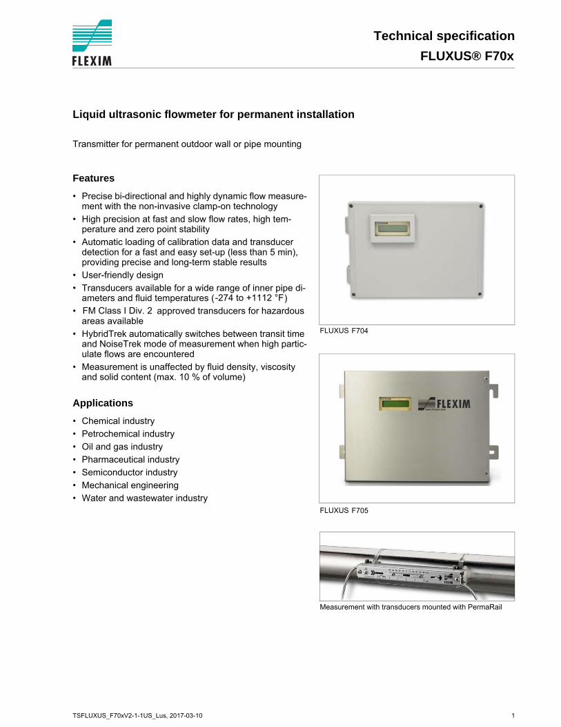
F704
F705
Liquid ultrasonic flowmeter for permanent installation
Transmitter for permanent outdoor wall or pipe mounting
Features
• Precise bi-directional and highly dynamic flow measure-ment with the non-invasive clamp-on technology
• High precision at fast and slow flow rates, high tem-perature and zero point stability
• Automatic loading of calibration data and transducer detection for a fast and easy set-up (less than 5 min), providing precise and long-term stable results
• User-friendly design
• Transducers available for a wide range of inner pipe di-ameters and fluid temperatures ( )
• approved transducers for hazardous areas available
• HybridTrek automatically switches between transit time and NoiseTrek mode of measurement when high partic-ulate flows are encountered
• Measurement is unaffected by fluid density, viscosity and solid content (max. 10 % of volume)
Applications
• Chemical industry
• Petrochemical industry
• Oil and gas industry
• Pharmaceutical industry
• Semiconductor industry
• Mechanical engineering
• Water and wastewater industry
-274 to +1112 °F
FM Class I Div. 2
FLUXUS® F70x Technical specification
Table of contents
TSFLUXUS_F70xV2-1-1US_Lus, 2017-03-102
Function ........................................................................................................................................................... 3Measurement principle...................................................................................................................................... 3Calculation of volumetric flow rate .................................................................................................................... 3Number of sound paths..................................................................................................................................... 4Typical measurement setup .............................................................................................................................. 5
Flow transmitter .............................................................................................................................................. 6Technical data................................................................................................................................................... 6Dimensions ....................................................................................................................................................... 92" pipe mounting kit (optional)......................................................................................................................... 11Terminal assignment....................................................................................................................................... 12
Transducers................................................................................................................................................... 13Transducer selection....................................................................................................................................... 13Transducer order code.................................................................................................................................... 14Technical data................................................................................................................................................. 15
Transducer mounting fixture ....................................................................................................................... 20
Coupling materials for transducers ............................................................................................................ 23
Connection systems ..................................................................................................................................... 24Transducer cable ............................................................................................................................................ 24
Junction box .................................................................................................................................................. 25Technical data................................................................................................................................................. 25Dimensions ..................................................................................................................................................... 252 " pipe mounting kit (optional)........................................................................................................................ 25Terminal assignment....................................................................................................................................... 26
Clamp-on temperature probe (optional) ..................................................................................................... 27
TSFLUXUS_F70xV2-1-1US_Lus, 2017-03-10 3
Technical specification FLUXUS® F70x
Function
Measurement principle
Transit time difference principle
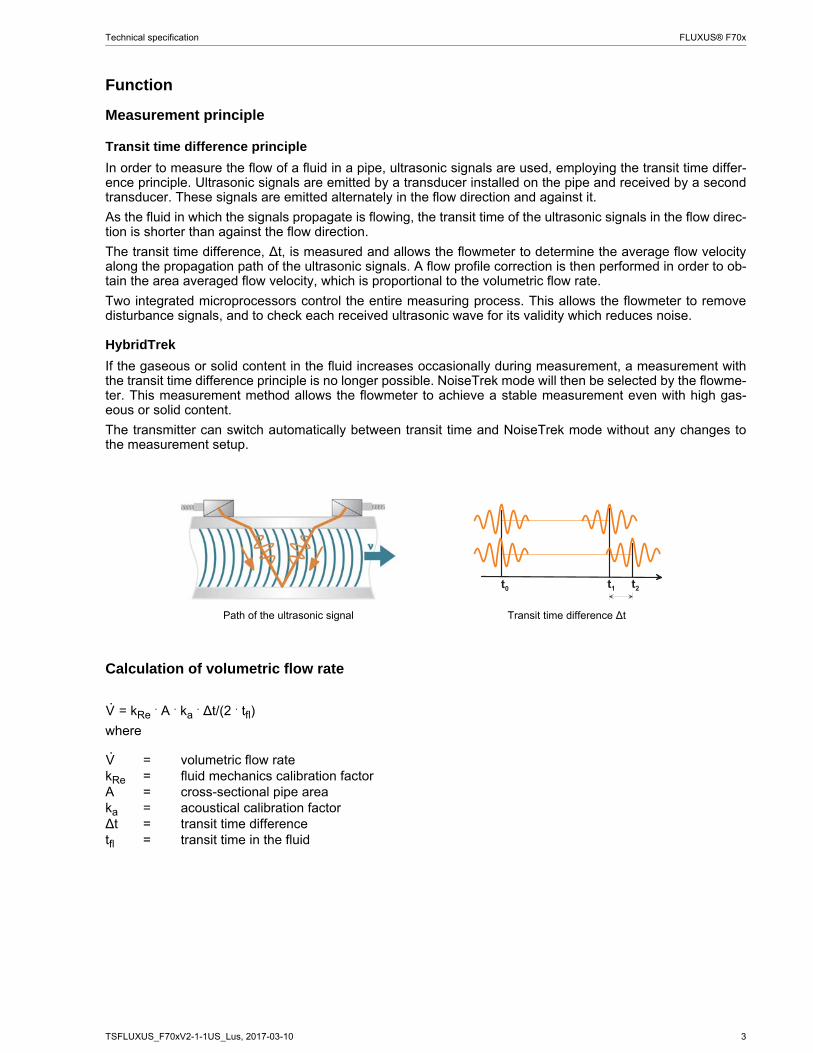
In order to measure the flow of a fluid in a pipe, ultrasonic signals are used, employing the transit time differ-ence principle. Ultrasonic signals are emitted by a transducer installed on the pipe and received by a secondtransducer. These signals are emitted alternately in the flow direction and against it.
As the fluid in which the signals propagate is flowing, the transit time of the ultrasonic signals in the flow direc-tion is shorter than against the flow direction.
The transit time difference, ∆t, is measured and allows the flowmeter to determine the average flow velocityalong the propagation path of the ultrasonic signals. A flow profile correction is then performed in order to ob-tain the area averaged flow velocity, which is proportional to the volumetric flow rate.
Two integrated microprocessors control the entire measuring process. This allows the flowmeter to removedisturbance signals, and to check each received ultrasonic wave for its validity which reduces noise.
HybridTrek
If the gaseous or solid content in the fluid increases occasionally during measurement, a measurement withthe transit time difference principle is no longer possible. NoiseTrek mode will then be selected by the flowme-ter. This measurement method allows the flowmeter to achieve a stable measurement even with high gas-eous or solid content.
The transmitter can switch automatically between transit time and NoiseTrek mode without any changes tothe measurement setup.
Calculation of volumetric flow rate
= kRe . A . ka . ∆t/(2 . tfl)
where
Path of the ultrasonic signal Transit time difference ∆t
= volumetric flow ratekRe = fluid mechanics calibration factorA = cross-sectional pipe areaka = acoustical calibration factor∆t = transit time differencetfl = transit time in the fluid
V·
V·
4 TSFLUXUS_F70xV2-1-1US_Lus, 2017-03-10
FLUXUS® F70x Technical specification
Number of sound paths
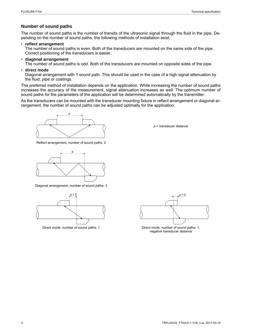
The number of sound paths is the number of transits of the ultrasonic signal through the fluid in the pipe. De-pending on the number of sound paths, the following methods of installation exist:
• reflect arrangementThe number of sound paths is even. Both of the transducers are mounted on the same side of the pipe. Correct positioning of the transducers is easier.
• diagonal arrangementThe number of sound paths is odd. Both of the transducers are mounted on opposite sides of the pipe.
• direct modeDiagonal arrangement with 1 sound path. This should be used in the case of a high signal attenuation by the fluid, pipe or coatings.
The preferred method of installation depends on the application. While increasing the number of sound pathsincreases the accuracy of the measurement, signal attenuation increases as well. The optimum number ofsound paths for the parameters of the application will be determined automatically by the transmitter.
As the transducers can be mounted with the transducer mounting fixture in reflect arrangement or diagonal ar-rangement, the number of sound paths can be adjusted optimally for the application..
a = transducer distance
Reflect arrangement, number of sound paths: 2
Diagonal arrangement, number of sound paths: 3
Direct mode, number of sound paths: 1 Direct mode, number of sound paths: 1,negative transducer distance
a
a
a > 0 a < 0
TSFLUXUS_F70xV2-1-1US_Lus, 2017-03-10 5
Technical specification FLUXUS® F70x
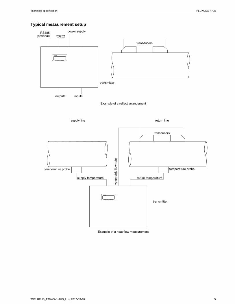
Typical measurement setup
Example of a reflect arrangement
Example of a heat flow measurement
transducers
transmitter
RS232
outputs inputs
power supplyRS485(optional)
transducers
transmitter
temperature probetemperature probe
supply line return line
volu
met
ric f
low
rat
e
supply temperature return temperature
6 TSFLUXUS_F70xV2-1-1US_Lus, 2017-03-10
FLUXUS® F70x Technical specification
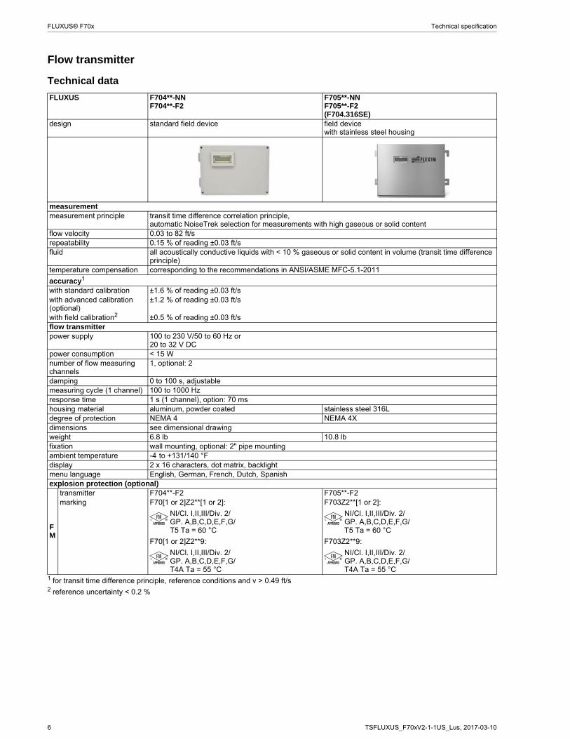
Flow transmitter
Technical data
FLUXUS F704**-NNF704**-F2
F705**-NNF705**-F2(F704.316SE)
design standard field device field devicewith stainless steel housing
measurementmeasurement principle transit time difference correlation principle,
automatic NoiseTrek selection for measurements with high gaseous or solid contentflow velocity 0.03 to 82 ft/srepeatability 0.15 % of reading ±0.03 ft/sfluid all acoustically conductive liquids with < 10 % gaseous or solid content in volume (transit time difference
principle)temperature compensation corresponding to the recommendations in ANSI/ASME MFC-5.1-2011
accuracy1
with standard calibration ±1.6 % of reading ±0.03 ft/swith advanced calibration (optional)
±1.2 % of reading ±0.03 ft/s
with field calibration2 ±0.5 % of reading ±0.03 ft/sflow transmitterpower supply 100 to 230 V/50 to 60 Hz or
20 to 32 V DCpower consumption < 15 Wnumber of flow measuring channels
1, optional: 2
damping 0 to 100 s, adjustablemeasuring cycle (1 channel) 100 to 1000 Hzresponse time 1 s (1 channel), option: 70 mshousing material aluminum, powder coated stainless steel 316Ldegree of protection NEMA 4 NEMA 4Xdimensions see dimensional drawingweight 6.8 lb 10.8 lbfixation wall mounting, optional: 2" pipe mountingambient temperature -4 to +131/140 °Fdisplay 2 x 16 characters, dot matrix, backlightmenu language English, German, French, Dutch, Spanishexplosion protection (optional)
FM
transmitter F704**-F2 F705**-F2marking F70[1 or 2]Z2**[1 or 2]:
NI/Cl. I,II,III/Div. 2/GP. A,B,C,D,E,F,G/T5 Ta = 60 °C
F70[1 or 2]Z2**9:
NI/Cl. I,II,III/Div. 2/GP. A,B,C,D,E,F,G/T4A Ta = 55 °C
F703Z2**[1 or 2]:
NI/Cl. I,II,III/Div. 2/GP. A,B,C,D,E,F,G/T5 Ta = 60 °C
F703Z2**9:
NI/Cl. I,II,III/Div. 2/GP. A,B,C,D,E,F,G/T4A Ta = 55 °C
1 for transit time difference principle, reference conditions and v > 0.49 ft/s2 reference uncertainty < 0.2 %
TSFLUXUS_F70xV2-1-1US_Lus, 2017-03-10 7
Technical specification FLUXUS® F70x
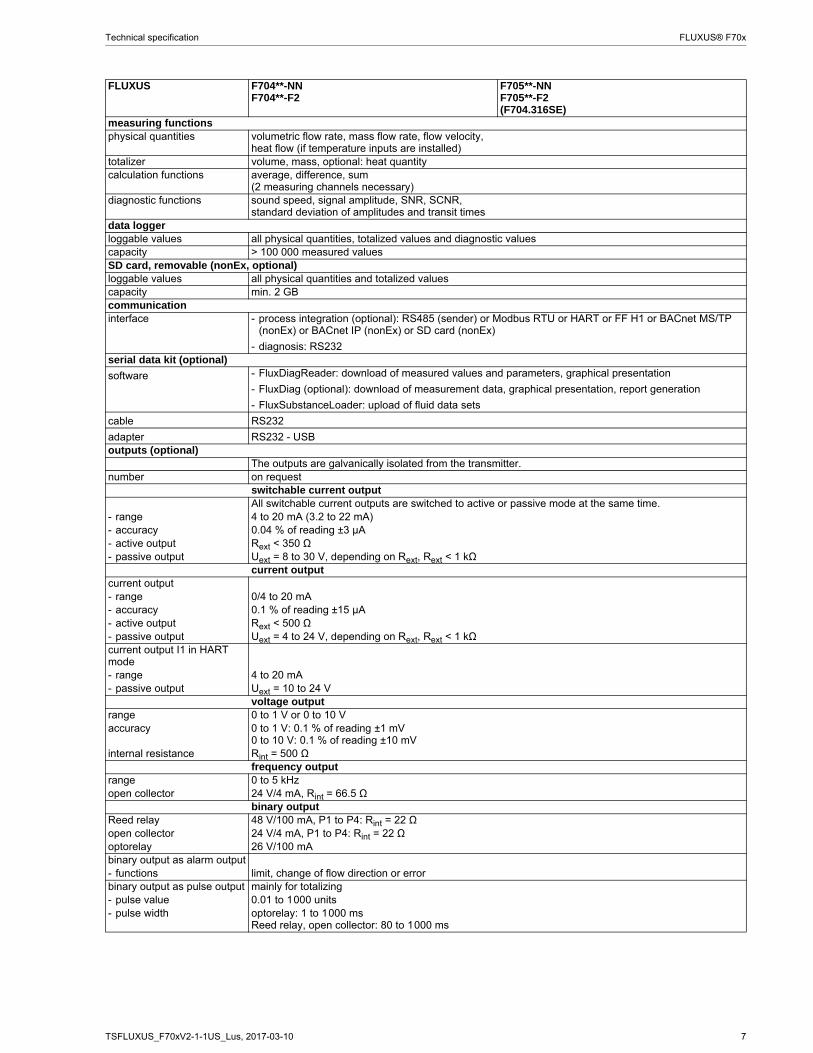
measuring functionsphysical quantities volumetric flow rate, mass flow rate, flow velocity,
heat flow (if temperature inputs are installed)totalizer volume, mass, optional: heat quantitycalculation functions average, difference, sum
(2 measuring channels necessary)diagnostic functions sound speed, signal amplitude, SNR, SCNR,
standard deviation of amplitudes and transit timesdata loggerloggable values all physical quantities, totalized values and diagnostic valuescapacity > 100 000 measured valuesSD card, removable (nonEx, optional)loggable values all physical quantities and totalized valuescapacity min. 2 GBcommunicationinterface - process integration (optional): RS485 (sender) or Modbus RTU or HART or FF H1 or BACnet MS/TP
(nonEx) or BACnet IP (nonEx) or SD card (nonEx)
- diagnosis: RS232serial data kit (optional)
software - FluxDiagReader: download of measured values and parameters, graphical presentation
- FluxDiag (optional): download of measurement data, graphical presentation, report generation
- FluxSubstanceLoader: upload of fluid data sets
сable RS232
adapter RS232 - USBoutputs (optional)
The outputs are galvanically isolated from the transmitter.number on request
switchable current outputAll switchable current outputs are switched to active or passive mode at the same time.
- range 4 to 20 mA (3.2 to 22 mA)- accuracy 0.04 % of reading ±3 μA- active output Rext < 350 Ω- passive output Uext = 8 to 30 V, depending on Rext, Rext < 1 kΩ
current outputcurrent output- range 0/4 to 20 mA- accuracy 0.1 % of reading ±15 μA- active output Rext < 500 Ω- passive output Uext = 4 to 24 V, depending on Rext, Rext < 1 kΩcurrent output I1 in HART mode- range 4 to 20 mA- passive output Uext = 10 to 24 V
voltage outputrange 0 to 1 V or 0 to 10 Vaccuracy 0 to 1 V: 0.1 % of reading ±1 mV
0 to 10 V: 0.1 % of reading ±10 mVinternal resistance Rint = 500 Ω
frequency outputrange 0 to 5 kHzopen collector 24 V/4 mA, Rint = 66.5 Ω
binary outputReed relay 48 V/100 mA, P1 to P4: Rint = 22 Ωopen collector 24 V/4 mA, P1 to P4: Rint = 22 Ωoptorelay 26 V/100 mAbinary output as alarm output- functions limit, change of flow direction or errorbinary output as pulse output mainly for totalizing- pulse value 0.01 to 1000 units- pulse width optorelay: 1 to 1000 ms
Reed relay, open collector: 80 to 1000 ms
FLUXUS F704**-NNF704**-F2
F705**-NNF705**-F2(F704.316SE)
8 TSFLUXUS_F70xV2-1-1US_Lus, 2017-03-10
FLUXUS® F70x Technical specification
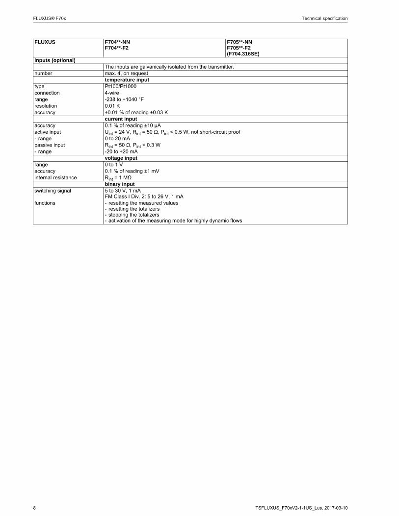
inputs (optional)The inputs are galvanically isolated from the transmitter.
number max. 4, on requesttemperature input
type Pt100/Pt1000connection 4-wirerange -238 to +1040 °Fresolution 0.01 Kaccuracy ±0.01 % of reading ±0.03 K
current inputaccuracy 0.1 % of reading ±10 μAactive input Uint = 24 V, Rint = 50 Ω, Pint < 0.5 W, not short-circuit proof- range 0 to 20 mApassive input Rint = 50 Ω, Pint < 0.3 W- range -20 to +20 mA
voltage inputrange 0 to 1 Vaccuracy 0.1 % of reading ±1 mVinternal resistance Rint = 1 MΩ
binary inputswitching signal 5 to 30 V, 1 mA
FM Class I Div. 2: 5 to 26 V, 1 mAfunctions - resetting the measured values
- resetting the totalizers- stopping the totalizers- activation of the measuring mode for highly dynamic flows
FLUXUS F704**-NNF704**-F2
F705**-NNF705**-F2(F704.316SE)
TSFLUXUS_F70xV2-1-1US_Lus, 2017-03-10 9
Technical specification FLUXUS® F70x
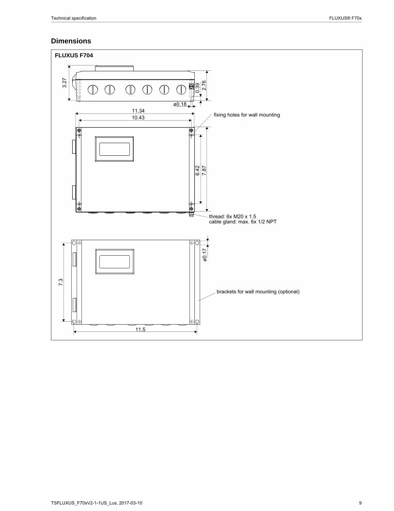
Dimensions
FLUXUS F704
2.76
0.39
ø0.18
6.4
27.
87
11.3410.43 fixing holes for wall mounting
thread: 6x M20 x 1.5cable gland: max. 6x 1/2 NPT
3.27
11.5
ø0.
17
7.3
brackets for wall mounting (optional)
10 TSFLUXUS_F70xV2-1-1US_Lus, 2017-03-10
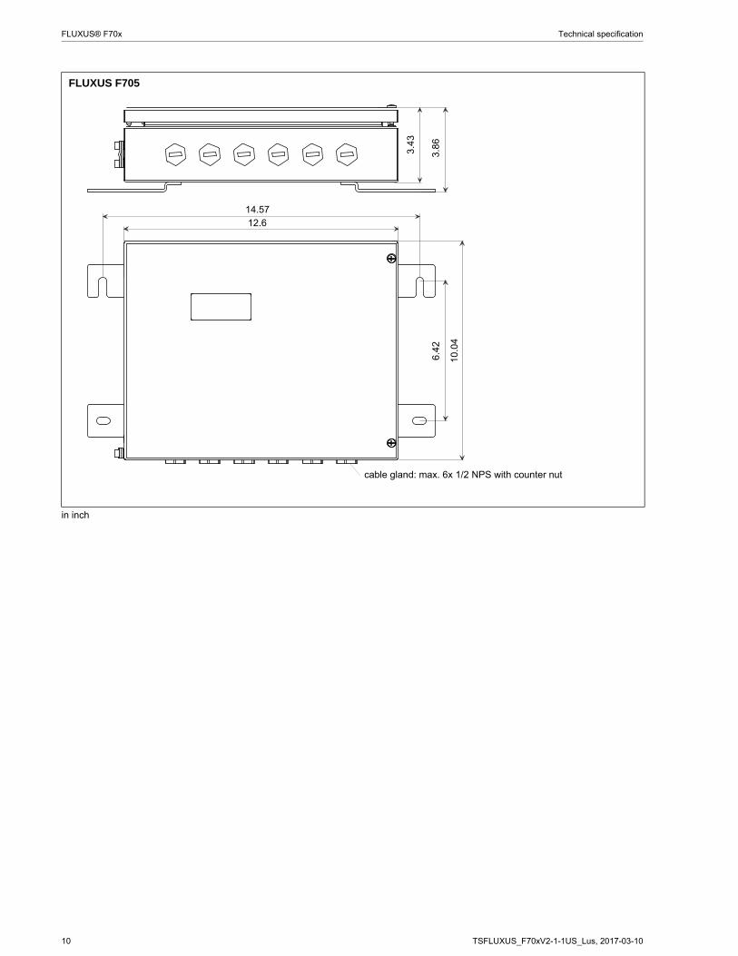
FLUXUS® F70x Technical specification
FLUXUS F705
in inch
6.42
12.6
cable gland: max. 6x 1/2 NPS with counter nut
14.57
10.0
4
3.4
3
3.86
TSFLUXUS_F70xV2-1-1US_Lus, 2017-03-10 11
Technical specification FLUXUS® F70x
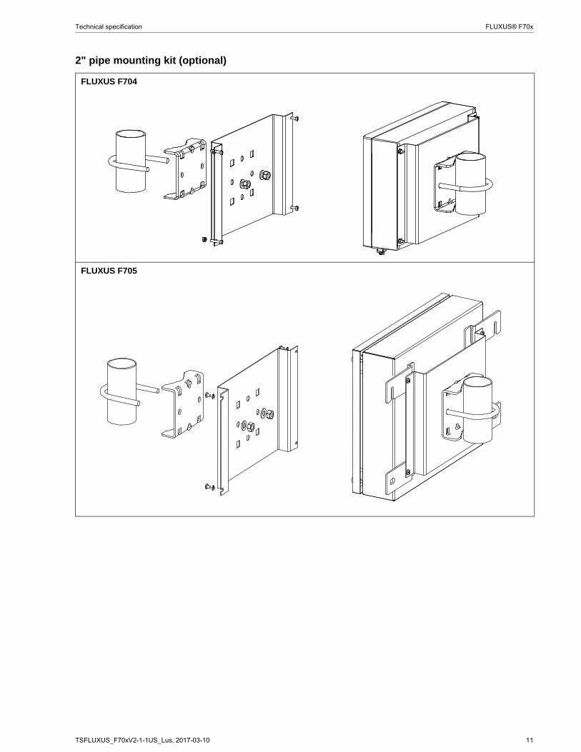
2" pipe mounting kit (optional)
FLUXUS F704
FLUXUS F705
12 TSFLUXUS_F70xV2-1-1US_Lus, 2017-03-10
FLUXUS® F70x Technical specification
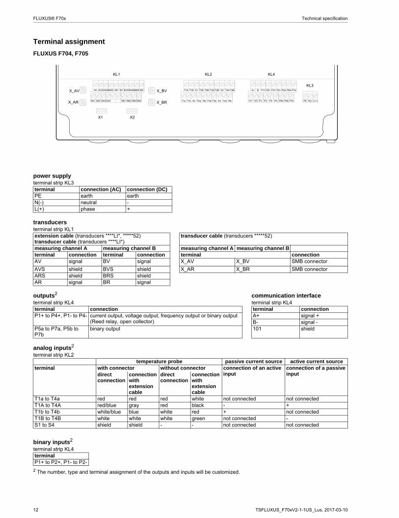
Terminal assignment
2 The number, type and terminal assignment of the outputs and inputs will be customized.
FLUXUS F704, F705
power supplyterminal strip KL3terminal connection (AC) connection (DC)PE earth earthN(-) neutral -L(+) phase +
transducersterminal strip KL1extension cable (transducers ****LI*, *****52)transducer cable (transducers ****LI*)
transducer cable (transducers *****52)
measuring channel A measuring channel B measuring channel A measuring channel Bterminal connection terminal connection terminal connectionAV signal BV signal X_AV X_BV SMB connector
AVS shield BVS shield X_AR X_BR SMB connectorARS shield BRS shieldAR signal BR signal
outputs2 communication interfaceterminal strip KL4 terminal strip KL4terminal connection terminal connectionP1+ to P4+, P1- to P4- current output, voltage output, frequency output or binary output
(Reed relay, open collector)A+ signal +B- signal -
P5a to P7a, P5b to P7b
binary output 101 shield
analog inputs2
terminal strip KL2temperature probe passive current source active current source
terminal with connector without connector connection of an active input
connection of a passive inputdirect
connectionconnection with extension cable
direct connection
connection with extension cable
T1a to T4a red red red white not connected not connectedT1A to T4A red/blue gray red black - +T1b to T4b white/blue blue white red + not connectedT1B to T4B white white white green not connected -S1 to S4 shield shield - - not connected not connected
binary inputs2
terminal strip KL4terminalP1+ to P2+, P1- to P2-
! " ! # # #
$ $ $
# $ # $ # $ # $
"
"
"
% % & % % &
"
' %
'
' %
'
TSFLUXUS_F70xV2-1-1US_Lus, 2017-03-10 13
Technical specification FLUXUS® F70x
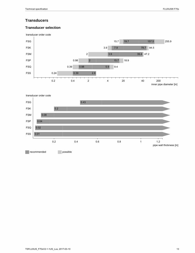
Transducers
Transducer selection
transducer order code
FSG 15.7 19.7 157.5 255.9
FSK 3.9 7.9 78.7 94.5
FSM 2 3.9 39.4 47.2
FSP 0.98 2 15.7 18.9
FSQ 0.39 0.98 5.9 9.4
FSS 0.24 0.39 2.8
0.2 0.4 2 4 20 40 200inner pipe diameter [in]
transducer order code
FSG 0.43
FSK 0.2
FSM 0.08
FSP 0.04
FSQ 0.02
FSS 0.01
0.2 0.4 0.6 0.8 1 1.2pipe wall thickness [in]
recommended possible
14 TSFLUXUS_F70xV2-1-1US_Lus, 2017-03-10
FLUXUS® F70x Technical specification
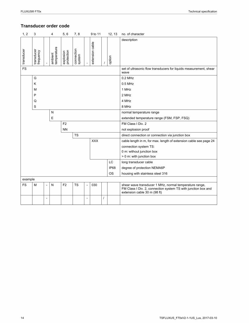
Transducer order code
1, 2 3 4 5, 6 7, 8 9 to 11 12, 13 no. of character
tran
sduc
er
tran
sduc
er
freq
uenc
y
- am
bien
t te
mpe
ratu
re
exp
losi
on
pro
tect
ion
conn
ect
ion
syst
em
- ext
ensi
on c
able
/ opt
ion
description
FS set of ultrasonic flow transducers for liquids measurement, shear wave
G 0.2 MHz
K 0.5 MHz
M 1 MHz
P 2 MHz
Q 4 MHz
S 8 MHz
N normal temperature range
E extended temperature range (FSM, FSP, FSQ)
F2 FM Class I Div. 2
NN not explosion proof
TS direct connection or connection via junction box
XXX cable length in m, for max. length of extension cable see page 24
connection system TS:
0 m: without junction box
> 0 m: with junction box
LC long transducer cable
IP68 degree of protection NEMA6P
OS housing with stainless steel 316
example
FS M - N F2 TS - 030 shear wave transducer 1 MHz, normal temperature range, FM Class I Div. 2, connection system TS with junction box and extension cable 30 m (98 ft)
- - /
TSFLUXUS_F70xV2-1-1US_Lus, 2017-03-10 15
Technical specification FLUXUS® F70x
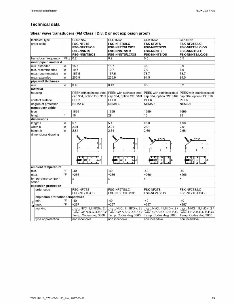
Technical data
Shear wave transducers (FM Class I Div. 2 or not explosion proof)
technical type CDG1N52 CLG1N52 CDK1N52 CLK1N52order code FSG-NF2TS
FSG-NF2TS/OSFSG-NF2TS/LCFSG-NF2TS/LC/OS
FSK-NF2TSFSK-NF2TS/OS
FSK-NF2TS/LCFSK-NF2TS/LC/OS
FSG-NNNTSFSG-NNNTS/OS
FSG-NNNTS/LCFSG-NNNTS/LC/OS
FSK-NNNTSFSK-NNNTS/OS
FSK-NNNTS/LCFSK-NNNTS/LC/OS
transducer frequency MHz 0.2 0.2 0.5 0.5inner pipe diameter dmin. extended in 15.7 15.7 3.9 3.9min. recommended in 19.7 19.7 7.9 7.9max. recommended in 157.5 157.5 78.7 78.7max. extended in 255.9 255.9 94.5 94.5pipe wall thicknessmin. in 0.43 0.43 0.2 0.2materialhousing PEEK with stainless steel
cap 304, option OS: 316LPEEK with stainless steel cap 304, option OS: 316L
PEEK with stainless steel cap 304, option OS: 316L
PEEK with stainless steel cap 304, option OS: 316L
contact surface PEEK PEEK PEEK PEEKdegree of protection NEMA 6 NEMA 6 NEMA 6 NEMA 6transducer cabletype 1699 1699 1699 1699length ft 16 29 16 29dimensionslength l in 5.1 5.1 4.98 4.98width b in 2.01 2.01 2.01 2.01height h in 2.64 2.64 2.66 2.66dimensional drawing
ambient temperaturemin. °F -40 -40 -40 -40max. °F +266 +266 +266 +266temperature compen-sation
x x x x
explosion protection
FM
order code FSG-NF2TSFSG-NF2TS/OS
FSG-NF2TS/LCFSG-NF2TS/LC/OS
FSK-NF2TSFSK-NF2TS/OS
FSK-NF2TS/LCFSK-NF2TS/LC/OS
explosion protection temperaturemin. °F -40 -40 -40 -40max. °F +257 +257 +257 +257marking NI/Cl. I,II,III/Div. 2 /
GP A,B,C,D,E,F,G/Temp. Codes dwg 3860
NI/Cl. I,II,III/Div. 2 /GP A,B,C,D,E,F,G/
Temp. Codes dwg 3860
NI/Cl. I,II,III/Div. 2 /GP A,B,C,D,E,F,G/
Temp. Codes dwg 3860
NI/Cl. I,II,III/Div. 2 /GP A,B,C,D,E,F,G/
Temp. Codes dwg 3860type of protection non incendive non incendive non incendive non incendive
l
hb
l
hb
l
hb
l
hb
16 TSFLUXUS_F70xV2-1-1US_Lus, 2017-03-10
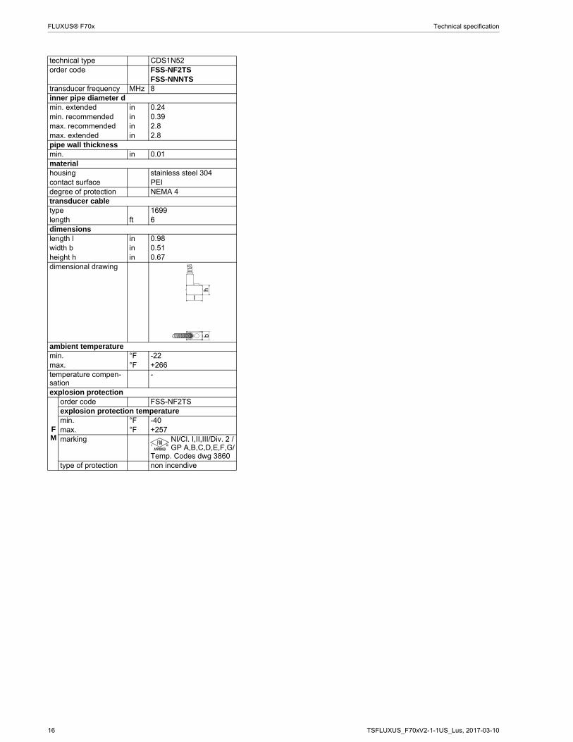
FLUXUS® F70x Technical specification
technical type CDS1N52order code FSS-NF2TS
FSS-NNNTStransducer frequency MHz 8inner pipe diameter dmin. extended in 0.24min. recommended in 0.39max. recommended in 2.8max. extended in 2.8pipe wall thicknessmin. in 0.01materialhousing stainless steel 304contact surface PEIdegree of protection NEMA 4transducer cabletype 1699length ft 6dimensionslength l in 0.98width b in 0.51height h in 0.67dimensional drawing
ambient temperaturemin. °F -22max. °F +266temperature compen-sation
-
explosion protection
FM
order code FSS-NF2TSexplosion protection temperaturemin. °F -40max. °F +257marking NI/Cl. I,II,III/Div. 2 /
GP A,B,C,D,E,F,G/Temp. Codes dwg 3860
type of protection non incendive
hb
l
TSFLUXUS_F70xV2-1-1US_Lus, 2017-03-10 17
Technical specification FLUXUS® F70x
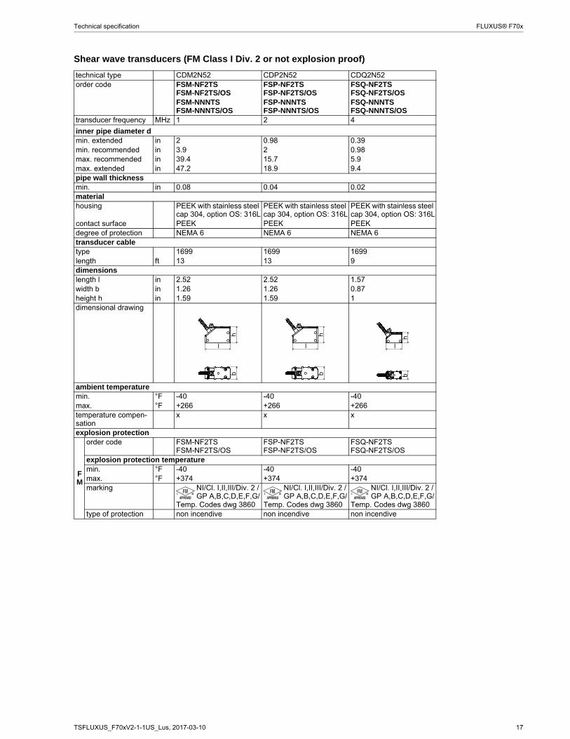
Shear wave transducers (FM Class I Div. 2 or not explosion proof)
technical type CDM2N52 CDP2N52 CDQ2N52order code FSM-NF2TS
FSM-NF2TS/OSFSP-NF2TSFSP-NF2TS/OS
FSQ-NF2TSFSQ-NF2TS/OS
FSM-NNNTSFSM-NNNTS/OS
FSP-NNNTSFSP-NNNTS/OS
FSQ-NNNTSFSQ-NNNTS/OS
transducer frequency MHz 1 2 4
inner pipe diameter dmin. extended in 2 0.98 0.39min. recommended in 3.9 2 0.98max. recommended in 39.4 15.7 5.9max. extended in 47.2 18.9 9.4pipe wall thicknessmin. in 0.08 0.04 0.02materialhousing PEEK with stainless steel
cap 304, option OS: 316LPEEK with stainless steel cap 304, option OS: 316L
PEEK with stainless steel cap 304, option OS: 316L
contact surface PEEK PEEK PEEKdegree of protection NEMA 6 NEMA 6 NEMA 6transducer cabletype 1699 1699 1699length ft 13 13 9dimensionslength l in 2.52 2.52 1.57width b in 1.26 1.26 0.87height h in 1.59 1.59 1dimensional drawing
ambient temperaturemin. °F -40 -40 -40max. °F +266 +266 +266temperature compen-sation
x x x
explosion protection
FM
order code FSM-NF2TSFSM-NF2TS/OS
FSP-NF2TSFSP-NF2TS/OS
FSQ-NF2TSFSQ-NF2TS/OS
explosion protection temperaturemin. °F -40 -40 -40max. °F +374 +374 +374marking NI/Cl. I,II,III/Div. 2 /
GP A,B,C,D,E,F,G/Temp. Codes dwg 3860
NI/Cl. I,II,III/Div. 2 /GP A,B,C,D,E,F,G/
Temp. Codes dwg 3860
NI/Cl. I,II,III/Div. 2 /GP A,B,C,D,E,F,G/
Temp. Codes dwg 3860type of protection non incendive non incendive non incendive
l
hb
l
hb
hb
l

18 TSFLUXUS_F70xV2-1-1US_Lus, 2017-03-10
FLUXUS® F70x Technical specification
Shear wave transducers (not explosion proof, NEMA 6P)
technical type CDG1LI8 CDK1LI8 CDM2LI8 CDP2LI8order code FSG-NNNTS/IP68 FSK-NNNTS/IP68 FSM-NNNTS/IP68 FSP-NNNTS/IP68transducer frequency MHz 0.2 0.5 1 2
inner pipe diameter dmin. extended in 15.7 3.9 2 0.98min. recommended in 19.7 7.9 3.9 2max. recommended in 157.5 78.7 39.4 15.7max. extended in 255.9 94.5 47.2 18.9pipe wall thicknessmin. in 0.43 0.2 0.08 0.04materialhousing PEEK with stainless steel
cap 316TiPEEK with stainless steel cap 316Ti
PEEK with stainless steel cap 316Ti
PEEK with stainless steel cap 316Ti
contact surface PEEK PEEK PEEK PEEKdegree of protection NEMA 6P NEMA 6P NEMA 6P NEMA 6Ptransducer cabletype 2550 2550 2550 2550length ft 39 39 39 39dimensionslength l in 5.12 5.12 2.76 2.76width b in 2.13 2.13 1.26 1.26height h in 3.29 3.29 1.81 1.81dimensional drawing
ambient temperaturemin. °F -40 -40 -40 -40max. °F +212 +212 +212 +212temperature compen-sation
x x x x
l
hb
l
hb
l
hb
l
hb
TSFLUXUS_F70xV2-1-1US_Lus, 2017-03-10 19
Technical specification FLUXUS® F70x
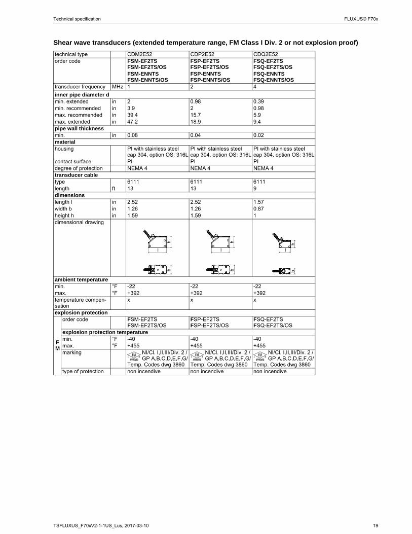
Shear wave transducers (extended temperature range, FM Class I Div. 2 or not explosion proof)
technical type CDM2E52 CDP2E52 CDQ2E52order code FSM-EF2TS
FSM-EF2TS/OSFSP-EF2TSFSP-EF2TS/OS
FSQ-EF2TSFSQ-EF2TS/OS
FSM-ENNTSFSM-ENNTS/OS
FSP-ENNTSFSP-ENNTS/OS
FSQ-ENNTSFSQ-ENNTS/OS
transducer frequency MHz 1 2 4
inner pipe diameter dmin. extended in 2 0.98 0.39min. recommended in 3.9 2 0.98max. recommended in 39.4 15.7 5.9max. extended in 47.2 18.9 9.4pipe wall thicknessmin. in 0.08 0.04 0.02materialhousing PI with stainless steel
cap 304, option OS: 316LPI with stainless steel cap 304, option OS: 316L
PI with stainless steel cap 304, option OS: 316L
contact surface PI PI PIdegree of protection NEMA 4 NEMA 4 NEMA 4transducer cabletype 6111 6111 6111length ft 13 13 9dimensionslength l in 2.52 2.52 1.57width b in 1.26 1.26 0.87height h in 1.59 1.59 1dimensional drawing
ambient temperaturemin. °F -22 -22 -22max. °F +392 +392 +392temperature compen-sation
x x x
explosion protection
FM
order code FSM-EF2TSFSM-EF2TS/OS
FSP-EF2TSFSP-EF2TS/OS
FSQ-EF2TSFSQ-EF2TS/OS
explosion protection temperaturemin. °F -40 -40 -40max. °F +455 +455 +455marking NI/Cl. I,II,III/Div. 2 /
GP A,B,C,D,E,F,G/Temp. Codes dwg 3860
NI/Cl. I,II,III/Div. 2 /GP A,B,C,D,E,F,G/
Temp. Codes dwg 3860
NI/Cl. I,II,III/Div. 2 /GP A,B,C,D,E,F,G/
Temp. Codes dwg 3860type of protection non incendive non incendive non incendive
l
hb
l
hb
hb
l
20 TSFLUXUS_F70xV2-1-1US_Lus, 2017-03-10
FLUXUS® F70x Technical specification
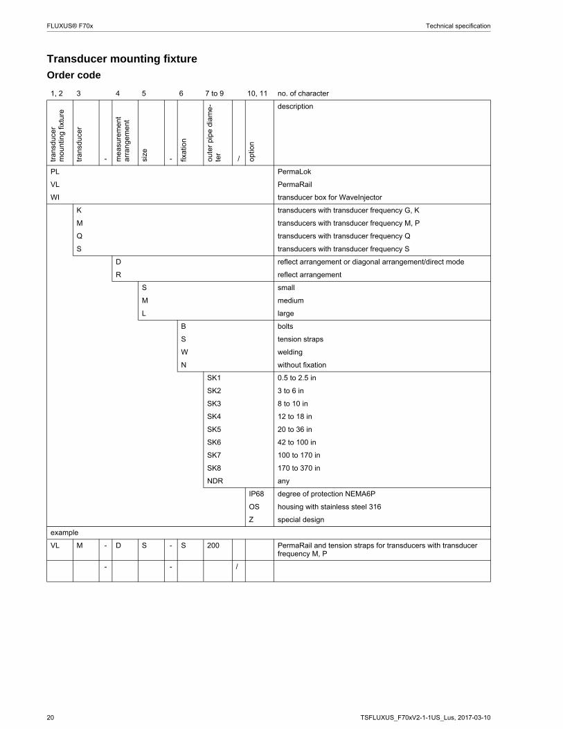
Transducer mounting fixture
Order code
1, 2 3 4 5 6 7 to 9 10, 11 no. of character
tran
sduc
er
mo
untin
g fi
xtur
e
tran
sduc
er
- me
asur
emen
t a
rran
gem
ent
size
- fixat
ion
out
er p
ipe
diam
e-te
r
/ opt
ion
description
PL PermaLok
VL PermaRail
WI transducer box for WaveInjector
K transducers with transducer frequency G, K
M transducers with transducer frequency M, P
Q transducers with transducer frequency Q
S transducers with transducer frequency S
D reflect arrangement or diagonal arrangement/direct mode
R reflect arrangement
S small
M medium
L large
B bolts
S tension straps
W welding
N without fixation
SK1 0.5 to 2.5 in
SK2 3 to 6 in
SK3 8 to 10 in
SK4 12 to 18 in
SK5 20 to 36 in
SK6 42 to 100 in
SK7 100 to 170 in
SK8 170 to 370 in
NDR any
IP68 degree of protection NEMA6P
OS housing with stainless steel 316
Z special design
example
VL M - D S - S 200 PermaRail and tension straps for transducers with transducer frequency M, P
- - /
TSFLUXUS_F70xV2-1-1US_Lus, 2017-03-10 21
Technical specification FLUXUS® F70x
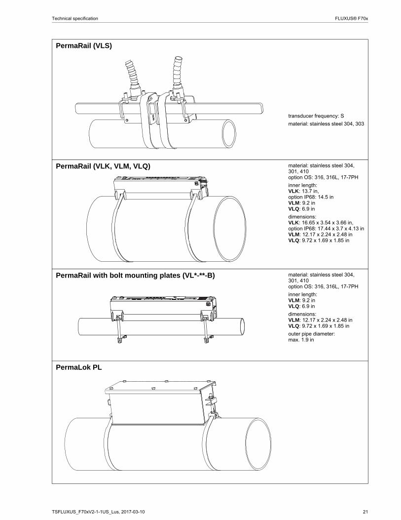
PermaRail (VLS)
transducer frequency: S
material: stainless steel 304, 303
PermaRail (VLK, VLM, VLQ) material: stainless steel 304, 301, 410option OS: 316, 316L, 17-7PH
inner length:VLK: 13.7 in,option IP68: 14.5 inVLM: 9.2 inVLQ: 6.9 in
dimensions:VLK: 16.65 x 3.54 x 3.66 in,option IP68: 17.44 x 3.7 x 4.13 inVLM: 12.17 x 2.24 x 2.48 inVLQ: 9.72 x 1.69 x 1.85 in
PermaRail with bolt mounting plates (VL*-**-B) material: stainless steel 304, 301, 410option OS: 316, 316L, 17-7PH
inner length:VLM: 9.2 inVLQ: 6.9 in
dimensions:VLM: 12.17 x 2.24 x 2.48 inVLQ: 9.72 x 1.69 x 1.85 in
outer pipe diameter:max. 1.9 in
PermaLok PL
22 TSFLUXUS_F70xV2-1-1US_Lus, 2017-03-10
FLUXUS® F70x Technical specification
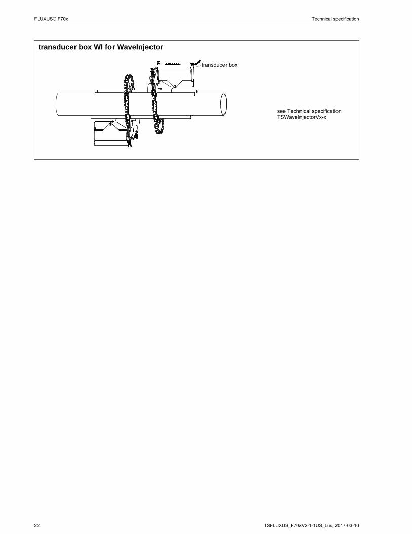
transducer box WI for WaveInjector
see Technical specificationTSWaveInjectorVx-x
transducer box
TSFLUXUS_F70xV2-1-1US_Lus, 2017-03-10 23
Technical specification FLUXUS® F70x
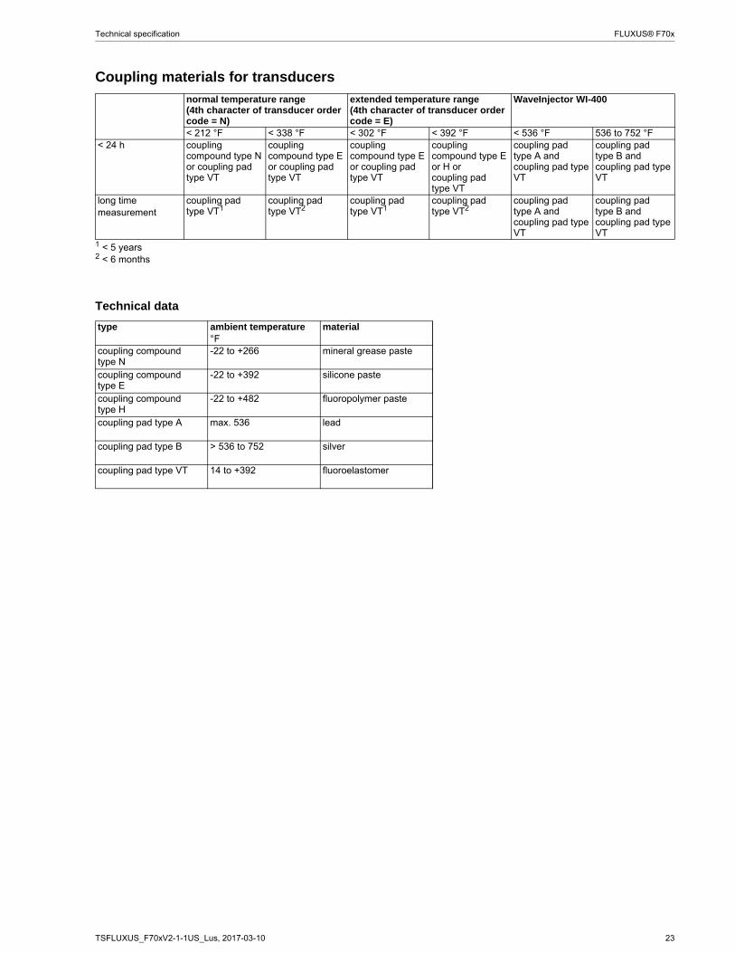
Coupling materials for transducers
Technical data
normal temperature range(4th character of transducer order code = N)
extended temperature range(4th character of transducer order code = E)
WaveInjector WI-400
< 212 °F < 338 °F < 302 °F < 392 °F < 536 °F 536 to 752 °F< 24 h coupling
compound type N or coupling pad type VT
coupling compound type E or coupling pad type VT
coupling compound type E or coupling pad type VT
coupling compound type E or H orcoupling pad type VT
coupling pad type A and coupling pad type VT
coupling pad type B and coupling pad type VT
long time measurement
coupling pad type VT1
coupling pad type VT2
coupling pad type VT1
coupling pad type VT2
coupling pad type A and coupling pad type VT
coupling pad type B and coupling pad type VT
1 < 5 years2 < 6 months
type ambient temperature material°F
coupling compound type N
-22 to +266 mineral grease paste
coupling compound type E
-22 to +392 silicone paste
coupling compound type H
-22 to +482 fluoropolymer paste
coupling pad type A max. 536 lead
coupling pad type B > 536 to 752 silver
coupling pad type VT 14 to +392 fluoroelastomer
24 TSFLUXUS_F70xV2-1-1US_Lus, 2017-03-10
FLUXUS® F70x Technical specification
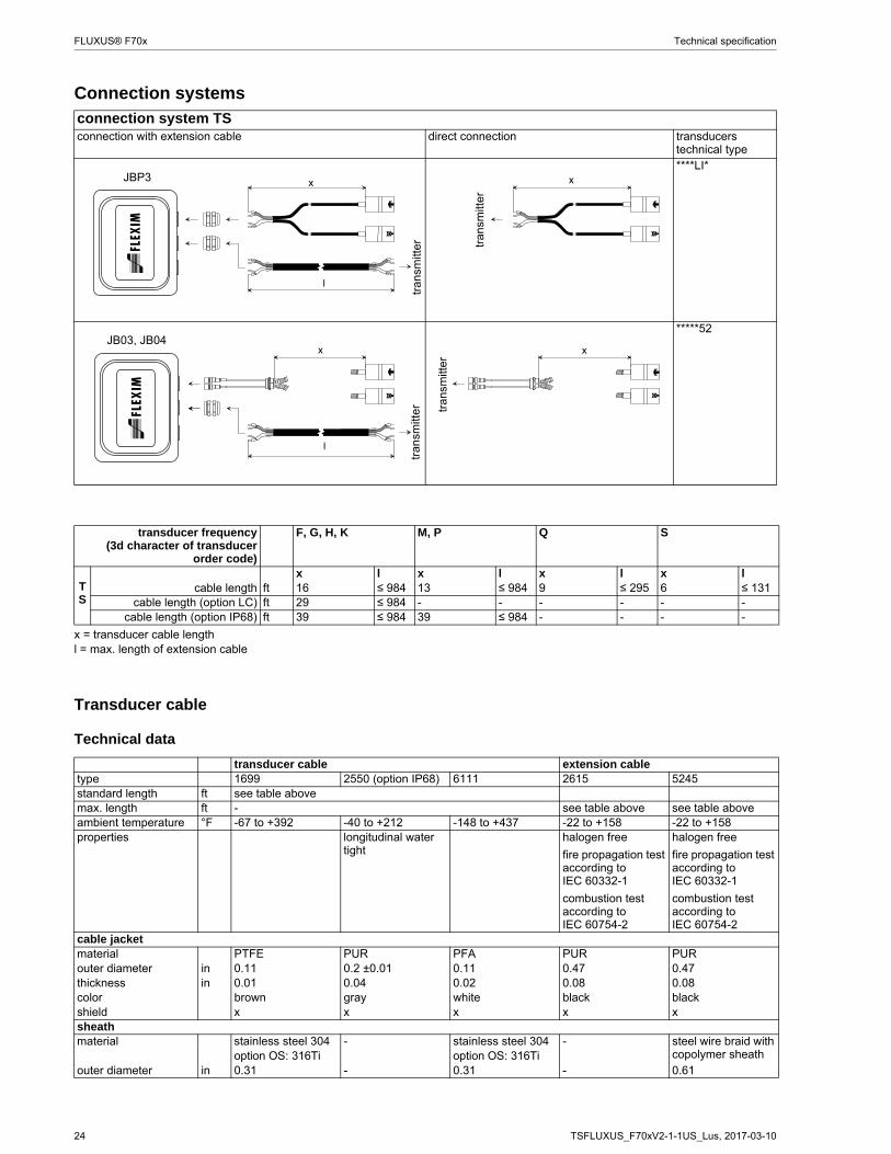
Connection systems
Transducer cable
Technical data
connection system TSconnection with extension cable direct connection transducers
technical type****LI*
*****52
transducer frequency(3d character of transducer
order code)
F, G, H, K M, P Q S
TS
x l x l x l x lcable length ft 16 ≤ 984 13 ≤ 984 9 ≤ 295 6 ≤ 131
cable length (option LC) ft 29 ≤ 984 - - - - - -cable length (option IP68) ft 39 ≤ 984 39 ≤ 984 - - - -
x = transducer cable lengthl = max. length of extension cable
transducer cable extension cabletype 1699 2550 (option IP68) 6111 2615 5245standard length ft see table abovemax. length ft - see table above see table aboveambient temperature °F -67 to +392 -40 to +212 -148 to +437 -22 to +158 -22 to +158properties longitudinal water
tighthalogen free
fire propagation test according to IEC 60332-1
combustion test according to IEC 60754-2
halogen free
fire propagation test according to IEC 60332-1
combustion test according to IEC 60754-2
cable jacketmaterial PTFE PUR PFA PUR PURouter diameter in 0.11 0.2 ±0.01 0.11 0.47 0.47thickness in 0.01 0.04 0.02 0.08 0.08color brown gray white black blackshield x x x x xsheathmaterial stainless steel 304 - stainless steel 304 - steel wire braid with
copolymer sheathoption OS: 316Ti option OS: 316Tiouter diameter in 0.31 - 0.31 - 0.61
tran
smitt
er
x
l
JBP3
tran
smitt
er
x
tran
smitt
er
x
l
JB03, JB04
tran
smitt
er
x
TSFLUXUS_F70xV2-1-1US_Lus, 2017-03-10 25
Technical specification FLUXUS® F70x
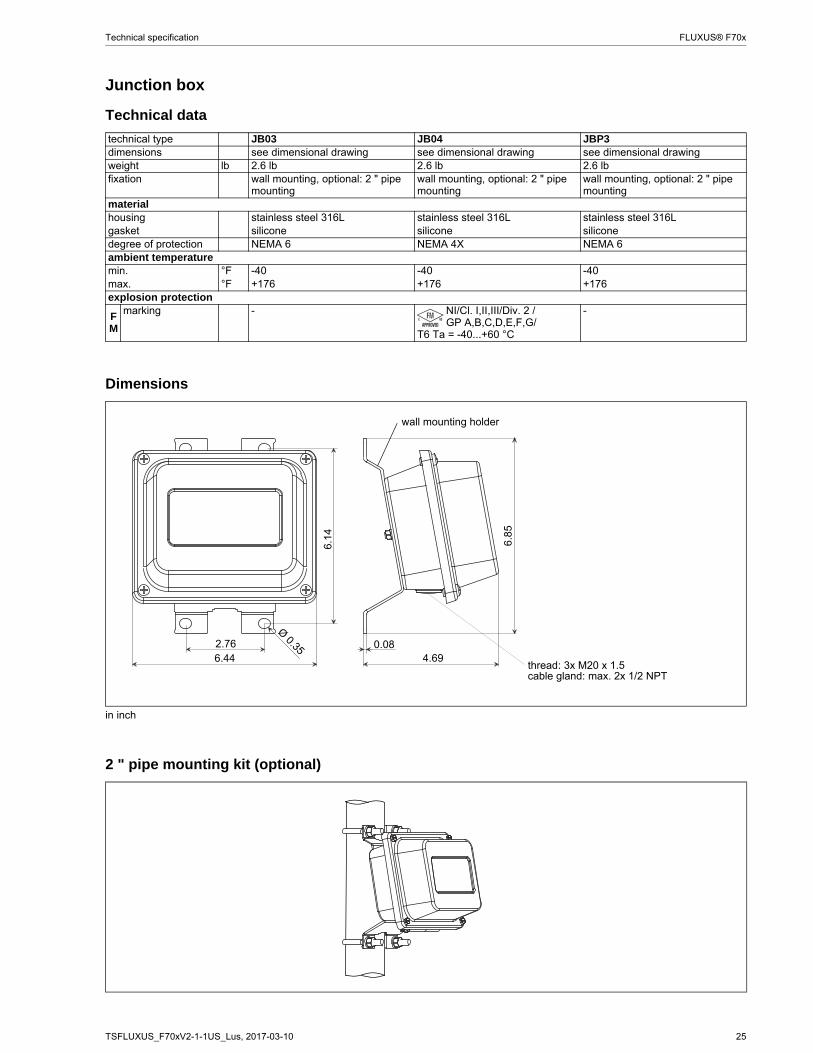
Junction box
Technical data
Dimensions
2 " pipe mounting kit (optional)
technical type JB03 JB04 JBP3dimensions see dimensional drawing see dimensional drawing see dimensional drawingweight lb 2.6 lb 2.6 lb 2.6 lbfixation wall mounting, optional: 2 " pipe
mountingwall mounting, optional: 2 " pipe mounting
wall mounting, optional: 2 " pipe mounting
materialhousing stainless steel 316L stainless steel 316L stainless steel 316Lgasket silicone silicone siliconedegree of protection NEMA 6 NEMA 4X NEMA 6ambient temperaturemin. °F -40 -40 -40max. °F +176 +176 +176explosion protection
FM
marking - NI/Cl. I,II,III/Div. 2 /GP A,B,C,D,E,F,G/
T6 Ta = -40...+60 °C
-
in inch
6.85
4.690.08
wall mounting holder
2.766.44
6.14
Ø 0.35
thread: 3x M20 x 1.5cable gland: max. 2x 1/2 NPT
26 TSFLUXUS_F70xV2-1-1US_Lus, 2017-03-10
FLUXUS® F70x Technical specification
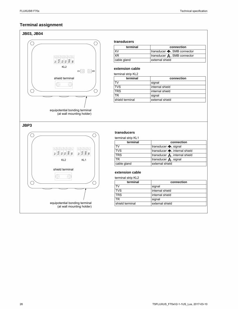
Terminal assignment
JB03, JB04
JBP3
%
"
%
%
&
&
transducers
terminal connectionXV transducer , SMB connectorXR transducer , SMB connectorcable gland external shield
extension cable
terminal strip KL2terminal connection
TV signalTVS internal shieldTRS internal shieldTR signalshield terminal external shield
shield terminal
equipotential bonding terminal(at wall mounting holder)
%
%
&
&
%
%
" "
transducers
terminal strip KL1terminal connection
TV transducer , signalTVS transducer , internal shieldTRS transducer , internal shieldTR transducer , signalcable gland external shield
extension cable
terminal strip KL2terminal connection
TV signalTVS internal shieldTRS internal shieldTR signalshield terminal external shield
shield terminal
equipotential bonding terminal(at wall mounting holder)
TSFLUXUS_F70xV2-1-1US_Lus, 2017-03-10 27
Technical specification FLUXUS® F70x
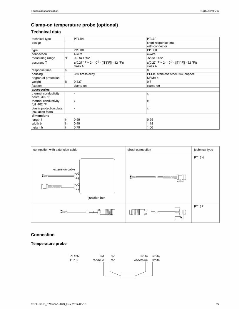
Clamp-on temperature probe (optional)
Technical data
Connection
Temperature probe
technical type PT13N PT13Fdesign short response time,
with connectortype Pt1000 Pt1000connection 4-wire 4-wiremeasuring range °F -40 to +392 -58 to +482
accuracy T ±(0.27 °F + 2 . 10-3 . (|T [°F]| - 32 °F))class A
±(0.27 °F + 2 . 10-3 . (|T [°F]| - 32 °F))class A
response time s 8housing 360 brass alloy PEEK, stainless steel 304, copperdegree of protection NEMA 4weight lb 0.437 0.7fixation clamp-on clamp-onaccessoriesthermal conductivity paste 392 °F
- x
thermal conductivity foil 482 °F
x x
plastic protection plate, insulation foam
- x
dimensionslength l in 0.59 0.55width b in 0.49 1.18height h in 0.79 1.06
connection with extension cable direct connection technical type
PT13N
PT13F
extension cable
junction box
lh
h
l
PT13N red red white whitePT13F red/blue red white/blue white
28 TSFLUXUS_F70xV2-1-1US_Lus, 2017-03-10
FLUXUS® F70x Technical specification
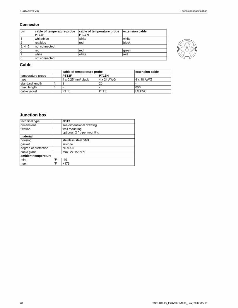
Connector
Cable
pin cable of temperature probe PT13F
cable of temperature probe PT13N
extension cable
1 white/blue white white2 red/blue red black3, 4, 5 not connected6 red red green7 white white red8 not connected
cable of temperature probe extension cabletemperature probe PT13F PT13Ntype 4 x 0.25 mm² black 4 x 24 AWG 4 x 18 AWGstandard length ft 9 20 -max. length ft - - 656cable jacket PTFE PTFE LS PVC
Junction boxtechnical type JBT3dimensions see dimensional drawingfixation wall mounting
optional: 2 " pipe mountingmaterialhousing stainless steel 316Lgasket siliconedegree of protection NEMA 6cable gland max. 2x 1/2 NPTambient temperaturemin. °F -40max. °F +176
TSFLUXUS_F70xV2-1-1US_Lus, 2017-03-10 29
Technical specification FLUXUS® F70x
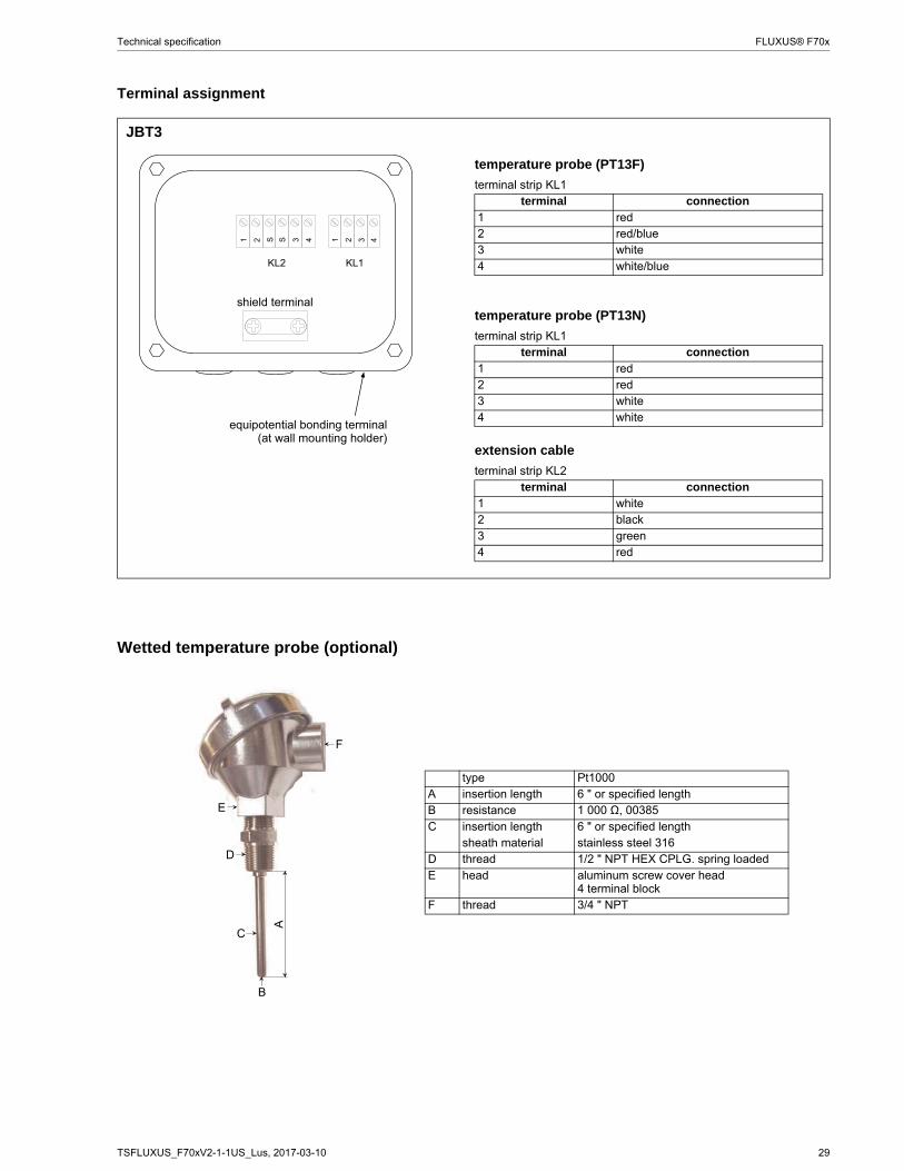
Terminal assignment
JBT3
Wetted temperature probe (optional)
" "
temperature probe (PT13F)
terminal strip KL1terminal connection
1 red2 red/blue3 white4 white/blue
temperature probe (PT13N)
terminal strip KL1terminal connection
1 red2 red3 white4 white
extension cable
terminal strip KL2terminal connection
1 white2 black3 green4 red
shield terminal
equipotential bonding terminal(at wall mounting holder)
type Pt1000A insertion length 6 " or specified lengthB resistance 1 000 Ω, 00385C insertion length 6 " or specified length
sheath material stainless steel 316D thread 1/2 " NPT HEX CPLG. spring loadedE head aluminum screw cover head
4 terminal blockF thread 3/4 " NPT

30 TSFLUXUS_F70xV2-1-1US_Lus, 2017-03-10
FLUXUS® F70x Technical specification
FLEXIM AMERICAS Corporation
Edgewood, NY 11717
USA
Tel.: (631) 492-2300
Fax: (631) 492-2117
internet: www.flexim.com
e-mail: [email protected]
1-888-852-7473
Subject to change without notification. Errors excepted.
FLUXUS® is a registered trademark of FLEXIM GmbH.