Liquid metal embrittlement of steel with galvanized coatings
9
IOP Conference Series: Materials Science and Engineering OPEN ACCESS Liquid metal embrittlement of steel with galvanized coatings To cite this article: J Mendala 2012 IOP Conf. Ser.: Mater. Sci. Eng. 35 012002 View the article online for updates and enhancements. You may also like Synthesis and Characterization of Zn 2 SiO 4 :Mn 2+ Nanophosphors Prepared from Different Zn Source in Liquid Precursor by Flame Spray Pyrolysis Jae Seok Lee, Aniruddh Khanna, Myounghwan Oh et al. - (Invited) Parylene C Based Adhesive Bonding on 6” and 8” Wafer Level for the Realization of Highly Reliable and Fully Biocompatible Microsystems Franz Selbmann, Mario Baum, Christoph Meinecke et al. - Improvement of adhesive joining of hybrid aluminum – GFRP using surface modifications M Berczeli and Z Weltsch - Recent citations Development of Bath Chemical Composition for Batch Hot-Dip Galvanizing—A Review Henryk Kania et al - Diffusion and cracking behavior involved in hot press forming of Zn coated 22MnB5 Hao Peng et al - Phase Composition and Microstructure of Zn Coated Press Hardening Steels for Direct Hot Stamping Vojtch Kuera et al - This content was downloaded from IP address 123.241.184.31 on 16/10/2021 at 09:55
Transcript of Liquid metal embrittlement of steel with galvanized coatings
IOP Conference Series: Materials Science and Engineering
OPEN ACCESS
Liquid metal embrittlement of steel with galvanizedcoatingsTo cite this article: J Mendala 2012 IOP Conf. Ser.: Mater. Sci. Eng. 35 012002
View the article online for updates and enhancements.
You may also likeSynthesis and Characterization ofZn2SiO4:Mn2+ Nanophosphors Preparedfrom Different Zn Source in LiquidPrecursor by Flame Spray PyrolysisJae Seok Lee, Aniruddh Khanna,Myounghwan Oh et al.
-
(Invited) Parylene C Based AdhesiveBonding on 6” and 8” Wafer Level for theRealization of Highly Reliable and FullyBiocompatible MicrosystemsFranz Selbmann, Mario Baum, ChristophMeinecke et al.
-
Improvement of adhesive joining of hybridaluminum – GFRP using surfacemodificationsM Berczeli and Z Weltsch
-
Recent citationsDevelopment of Bath ChemicalComposition for Batch Hot-DipGalvanizing—A ReviewHenryk Kania et al
-
Diffusion and cracking behavior involved inhot press forming of Zn coated 22MnB5Hao Peng et al
-
Phase Composition and Microstructure ofZn Coated Press Hardening Steels forDirect Hot StampingVojtch Kuera et al
-
This content was downloaded from IP address 123.241.184.31 on 16/10/2021 at 09:55
Liquid metal embrittlement of steel with galvanized coatings
J Mendala
Department of Materials Technology, Silesian University of Technology,
Krasinskiego 8, 40-019 Katowice, Poland
E-mail: [email protected]
Abstract. Article presents the state of knowledge relating occurrences of liquid metals
embrittlement. The results of experimental investigations of the LME phenomenon, reasons of
its formation and influence of different parameters are described. Selected ideas of the applied
research methods accessible in different works are presented. Samples made of C70D steel
with tensions stretching (400-800 MPa) at different values and kinds of loading during the hot
dip metallization were investigated. Coating processes in two bath: zinc and zinc with 2 % tin
addition were made. The processes of hot dip metallization were done at 450 °C temperature
and immersion time 180 s. Coated samples were investigated by light microscope to specify
possibility appear of LME effect.
1. Introduction
Commonly used constructional steels are easily affected by corrosion. Various methods of protecting
their surfaces are used to prevent this. Deposition of protective metal layers through dip coating is the
basic method of protecting steel elements against corrosion [1]. During this process, an element is
immersed in molten metal and thus, a direct contact occurs between the solid metal and liquid metal,
which usually leads to changes of mechanical properties and in extreme cases, even to premature
destruction of the element during its further operation. In 1928, Peter Rehbinder [2] initiated research
on the unknown phenomenon of cracking of steel structures previously subjected to a hot-dip
metallizing process. The effect of a surface-active medium on the mechanical properties of other
materials, called the Rehbinder effect, resulting from a drop in surface voltage, has been examined for
many types of solid bodies. The phenomenon of environment sensitive mechanical behaviour (ESMB)
of solid bodies is very diverse in terms of its occurrence and mechanisms. The most extreme form is
the decrease in strength and crushing of metals and alloys when in contact with liquid metal. It is this
form of ESMB that has been rendered responsible for a drastic decrease in ductility and brittle
cracking of metal (in a solid state) which was previously in direct contact with a liquid metal. This
phenomenon is referred to in the literature as liquid metal embrittlement (LME) or liquid metal
assisted cracking (LMAC) (figure 1) [3-5,9].
In the 60s of last century, this problem started attracting much attention from scientists and today,
extensive studies of the causes of LME are conducted. The interest in this phenomenon has been
additionally necessitated by the growing demands of clients who require manufacturers to use
engineering materials that will fulfil the expected utility functions in a reliable manner, for as long as
possible.
Finding an explanation for the mechanisms of the phenomenon allows finding solutions to certain
practical problems, such as protection against destruction caused by contact of a stressed material with
Technologies and Properties of Modern Utilised Materials IOP PublishingIOP Conf. Series: Materials Science and Engineering 35 (2012) 012002 doi:10.1088/1757-899X/35/1/012002
Published under licence by IOP Publishing Ltd 1

molten metal, or using the phenomenon to increase the efficacy of certain actions, such as crushing or
reaming of very hard metals.
Figure 1. LME of steel dipped in liquid tin at temperature 266 °C [3].
The risk of embrittlement induced by liquid metals has been confirmed, however, it is still difficult
to describe it because the knowledge of the phenomenon mechanisms is limited and the number of
parameters that seem to be responsible for LME is high. The results of experimental tests of LME
described in the literature [3,4] allowed presenting selected mechanisms which broaden the knowledge
about this phenomenon. The authors of this study have focused on a detailed examination of literature
discussing the LME phenomenon, its causes and the description of the test stands and research
methodologies used.
The paper presents a part of research on the influence of the chemical composition of liquid metal,
in this case of tin addition in a zinc bath, on the possibility of LME occurrence.
2. LME and the causes of its occurrence
LME can be defined as brittleness or a loss of ductility of a usually plastic material in the presence of
liquid metal. Some authors add to this definition the condition that external load or internal residual
stresses are necessary for LME to occur [4].
The results of conducted experiments have allowed the characterisation of the LME phenomenon.
First experiments consisted in examining the influence of a few parameters which were changed in an
inert medium and in a liquid metal environment. A number of parameters which may influence the
above-mentioned phenomenon were examined and described.
The main parameters that have a profound impact on the occurrence and course of embrittlement
under the influence of liquid metal are:
the fracture propagation rate – a characteristic feature of LME is a very high speed of fracture
propagation compared to the speed of propagation in the air or in a vacuum. A fracture occurs
after exceeding a certain threshold value of stress. The speed of propagation is mainly caused
by the fact that this phenomenon occurs with various intensity for the pair liquid metal – solid
metal [4,5];
deformation during fracture – in almost every case described in the literature, a tensile test
conducted in liquid metal demonstrates that stress during fracture is reduced, compared to the
same tests conducted in the air and in a vacuum;
stress curves – some discrepancies become apparent while comparing the stress curves
described in the literature [6,7]. Westwood and Stoloff believe that until a fracture occurs, the
stress of solid metal is the same as in the absence of immersion. Popovich [8] claims that
Technologies and Properties of Modern Utilised Materials IOP PublishingIOP Conf. Series: Materials Science and Engineering 35 (2012) 012002 doi:10.1088/1757-899X/35/1/012002
2

initial development of plastic flow takes place before a fracture. In both cases, elastic
properties remain unchanged in the presence of liquid metal;
the chemical composition of liquid metal – liquid metal influences the course of the
phenomenon at the end of a crack by decreasing the critical intensity of cracking stresses and
changing its micromechanisms. If we consider the effect of additives in liquid metal, they may
increase or decrease brittleness. The composition of liquid metal also modifies a number of
physicochemical parameters of the solid metal – liquid metal system (surface energy and
intersolubility), which is assumed to influence the LME mechanism [3,4,9];
the chemical composition of solid metal – the effect of alloying additions in various materials
on LME was the object of studies described in the literature. It was determined that some
additions increase the LME effect;
the microstructure of solid metal – the hardness and resistance to deformation of solid metal
during loading may affect its susceptibility to LME. An increase in the intensity of the
phenomenon may be compensated by cold plastic working, because it reduces the grain size. It
was determined [4] that LME intensifies when the grain size increases. There is a linear
dependence between the tensile force and grain diameter (d-1/2
). Furthermore, the brittle to
plastic transition increases as the temperature grows, due to the grain growth, and is a linear
dependence of temperature and log(d);
wettability – wetting is considered a prerequisite for the occurrence of LME. If contact
between the solid and liquid metal is very short or it is interrupted due to the presence of an
oxide film, LME does not occur [4,5];
surface energy and grain boundaries – surface energy SC and energy at grain boundaries Z are
the most important physicochemical parameters of the solid metal – liquid metal system in the
LME model described by Clegg [5].
Much progress has been made in the field of study of the effect of external parameters. Namely:
temperature – LME occurs in a certain range of temperature called “a drop in ductility”. This
property is usually considered to be a dependence of both the solid and liquid metal
compositions, as well as of the solid metal structure and external conditions. The lower
boundary of temperature required for the occurrence of LME depends on the properties of
a given liquid metal. Apart form that, the temperature has an effect on LME kinetics;
the deformation rate – the dependence between the deformation rate and the speed of crack
development is almost linear in certain solid metal – liquid metal systems [4]. During slow
deformation in conditions conducive to intensive relaxation of stresses, plastic flow is
weakened and can hinder the LME process. A reduction of the deformation rate at an
increased temperature leads to a decrease or decay of the range in which embrittlement occurs;
stress – where solid material is subject to constant stresses, a liquid metal will penetrate the
base material, thereby inducing cracks very similar to corrosion cracks. The speed of this
process changes depending on the temperature and the type of metal used. The closer the
melting point is, the faster the reaction proceeds. The damage caused in this way is
catastrophic and often confused with hydrogen embrittlement damage.
The LME phenomenon was analysed and described in the literature by using various research
methods which differ from one another mainly in terms of sample profiles and the method of applying
stress.
3. Test stand
The basic idea was to create a test stand that would facilitate the induction of tensile stresses in
a sample immersed in liquid metal. The sample was to be obtained from steel with a diameter no
bigger than 3.5 mm. A standard laboratory furnace was used to produce coatings in a batch hot-dip
metallizing. Such assumptions determined the requirements for the test stand. Figure 2 presents the
conception of the test stand design.
The LME test stand is comprised of two principal modules (figure 3):
Technologies and Properties of Modern Utilised Materials IOP PublishingIOP Conf. Series: Materials Science and Engineering 35 (2012) 012002 doi:10.1088/1757-899X/35/1/012002
3
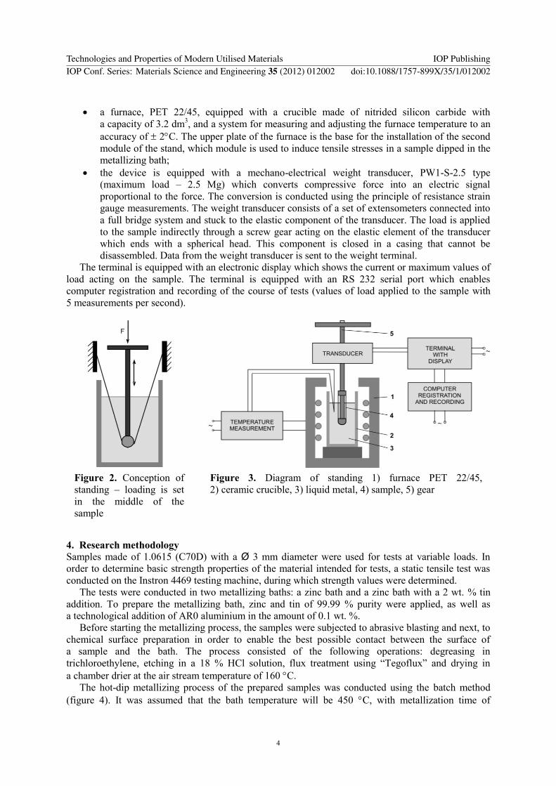
a furnace, PET 22/45, equipped with a crucible made of nitrided silicon carbide with
a capacity of 3.2 dm3, and a system for measuring and adjusting the furnace temperature to an
accuracy of 2C. The upper plate of the furnace is the base for the installation of the second
module of the stand, which module is used to induce tensile stresses in a sample dipped in the
metallizing bath;
the device is equipped with a mechano-electrical weight transducer, PW1-S-2.5 type
(maximum load – 2.5 Mg) which converts compressive force into an electric signal
proportional to the force. The conversion is conducted using the principle of resistance strain
gauge measurements. The weight transducer consists of a set of extensometers connected into
a full bridge system and stuck to the elastic component of the transducer. The load is applied
to the sample indirectly through a screw gear acting on the elastic element of the transducer
which ends with a spherical head. This component is closed in a casing that cannot be
disassembled. Data from the weight transducer is sent to the weight terminal.
The terminal is equipped with an electronic display which shows the current or maximum values of
load acting on the sample. The terminal is equipped with an RS 232 serial port which enables
computer registration and recording of the course of tests (values of load applied to the sample with
5 measurements per second).
Figure 2. Conception of
standing – loading is set
in the middle of the
sample
Figure 3. Diagram of standing 1) furnace PET 22/45,
2) ceramic crucible, 3) liquid metal, 4) sample, 5) gear
4. Research methodology
Samples made of 1.0615 (C70D) with a Ø 3 mm diameter were used for tests at variable loads. In
order to determine basic strength properties of the material intended for tests, a static tensile test was
conducted on the Instron 4469 testing machine, during which strength values were determined.
The tests were conducted in two metallizing baths: a zinc bath and a zinc bath with a 2 wt. % tin
addition. To prepare the metallizing bath, zinc and tin of 99.99 % purity were applied, as well as
a technological addition of AR0 aluminium in the amount of 0.1 wt. %.
Before starting the metallizing process, the samples were subjected to abrasive blasting and next, to
chemical surface preparation in order to enable the best possible contact between the surface of
a sample and the bath. The process consisted of the following operations: degreasing in
trichloroethylene, etching in a 18 % HCl solution, flux treatment using “Tegoflux” and drying in
a chamber drier at the air stream temperature of 160 C.
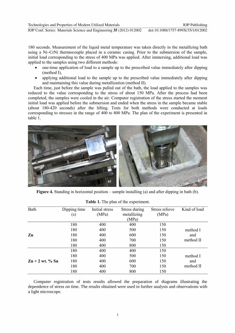
The hot-dip metallizing process of the prepared samples was conducted using the batch method
(figure 4). It was assumed that the bath temperature will be 450 C, with metallization time of
Technologies and Properties of Modern Utilised Materials IOP PublishingIOP Conf. Series: Materials Science and Engineering 35 (2012) 012002 doi:10.1088/1757-899X/35/1/012002
4
180 seconds. Measurement of the liquid metal temperature was taken directly in the metallizing bath
using a Ni–CrNi thermocouple placed in a ceramic casing. Prior to the submersion of the sample,
initial load corresponding to the stress of 400 MPa was applied. After immersing, additional load was
applied to the samples using two different methods:
one-time application of load to a sample up to the prescribed value immediately after dipping
(method I),
applying additional load to the sample up to the prescribed value immediately after dipping
and maintaining this value during metallization (method II).
Each time, just before the sample was pulled out of the bath, the load applied to the samples was
reduced to the value corresponding to the stress of about 150 MPa. After the process had been
completed, the samples were cooled in the air. Computer registration of the stress started the moment
initial load was applied before the submersion and ended when the stress in the sample became stable
(about 180-420 seconds) after the lifting. Tests for both methods were conducted at loads
corresponding to stresses in the range of 400 to 800 MPa. The plan of the experiment is presented in
table 1.
Figure 4. Standing in horizontal position – sample installing (a) and after dipping in bath (b).
Table 1. The plan of the experiment.
Bath Dipping time
(s)
Initial stress
(MPa)
Stress during
metallizing
(MPa)
Stress relieve
(MPa)
Kind of load
Zn
180 400 400 150
method I
and
method II
180 400 500 150
180 400 600 150
180 400 700 150
180 400 800 150
Zn + 2 wt. % Sn
180 400 400 150
method I
and
method II
180 400 500 150
180 400 600 150
180 400 700 150
180 400 800 150
Computer registration of tests results allowed the preparation of diagrams illustrating the
dependence of stress on time. The results obtained were used in further analysis and observations with
a light microscope.
a) b)
Technologies and Properties of Modern Utilised Materials IOP PublishingIOP Conf. Series: Materials Science and Engineering 35 (2012) 012002 doi:10.1088/1757-899X/35/1/012002
5

5. Tests results
While analyzing the curves obtained in method I (figures 5 a and 6 a), it can be noted that in each case,
there is a sudden decrease in stress from the initial load value to ca. 150 MPa during the first
15 seconds, which corresponds to the moment the sample is immersed in the metallizing bath. Next,
the stress increases due to the application of specific load, after which it decreases proportionally to
the increase of the load value. After unloading the samples, which is connected with pulling them up
from the metallizing bath, (i.e. after 180 s) and their cooling down, one can observe an increase of
stress up to a value independent from the applied initial load and specific load.
The course of curves obtained in the case of method II (figures 5 b and 6 b) is analogous to those
obtained in method I, with the only difference that the stress does not decrease after the application of
specific load, but is maintained at a certain level. The curve in the diagram for the sample that
underwent failure before the metallization process was completed is an exception to this. The tests for
a sample metallized in a Zn + 2 wt. % Sn bath subjected to a load corresponding to the stress of
800 MPa (method II) were repeated in order to verify the results.
0
100
200
300
400
500
600
700
800
900
0 50 100 150 200 250 300 350 400
Time, s
Str
ess,
MP
a
Zn (I) 400 MPa
Zn (I) 500 MPa
Zn (I) 600 MPa
Zn (I) 700 MPa
Zn (I) 800 MPa
a)
0
100
200
300
400
500
600
700
800
900
0 50 100 150 200 250 300 350 400
Time, s
Str
es
s,
MP
a
Zn (II) 400 MPa
Zn (II) 500 MPa
Zn (II) 600 MPa
Zn (II) 700 MPa
Zn (II) 800 MPa
b)
Figure 5. Stress vs. time diagram obtained during metallization of 1.0615 (C70D) steel samples in
Zn bath; load corresponding to the stress 400-800 MPa by: method I (a) and method II (b)
0
100
200
300
400
500
600
700
800
900
0 50 100 150 200 250 300 350 400
Time, s
Str
es
s,
MP
a
ZnSn (I) 400 MPa
ZnSn (I) 500 MPa
ZnSn (I) 600 MPa
ZnSn (I) 700 MPa
ZnSn (I) 800 MPa
a)
0
100
200
300
400
500
600
700
800
900
0 50 100 150 200 250 300 350 400
Time, s
Str
es
s,
MP
a
ZnSn (II) 400 MPa
ZnSn (II) 500 MPa
ZnSn (II) 600 MPa
ZnSn (II) 700 MPa
ZnSn (II) 800 MPa
b)
Figure 6. Stress vs. time diagram obtained during metallization of 1.0615 (C70D) steel samples in
Zn + 2 wt. % Sn bath; load corresponding to the stress 400-800 MPa by: method I (a) and
method II (b)
Based on the above-mentioned results, it can be affirmed that the tin addition introduced into the
metallizing bath may decrease the strength properties of the product being coated, meaning that in the
Technologies and Properties of Modern Utilised Materials IOP PublishingIOP Conf. Series: Materials Science and Engineering 35 (2012) 012002 doi:10.1088/1757-899X/35/1/012002
6
metallized component, where the described stress value is present, cracking may occur or the
component may be completely destroyed.
All obtained coated components underwent metallographic tests using a light microscope in order
to assess the possibility of the LME occurrence. The structure of components with coatings, obtained
in both tested bath and subjected to stresses by means of method I, did not show the occurrence of
fractures in the substrate material or the coating area. The situation was similar in the case where stress
was applied according to method II during the metallization process in a zinc bath, where no fractures
were found (figures 7a and b). On the other hand, in the case of applying stress during metallization in
a zinc bath with an addition of tin (figures 7c and d), for higher stress values (600-800 MPa) small
fractures were detected in the coating which were vertical to the substrate and the sample was ruptured
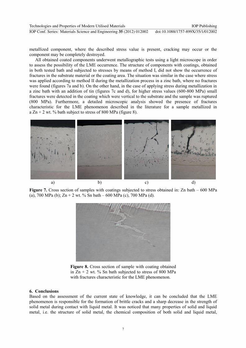
(800 MPa). Furthermore, a detailed microscopic analysis showed the presence of fractures
characteristic for the LME phenomenon described in the literature for a sample metallized in
a Zn + 2 wt. % bath subject to stress of 800 MPa (figure 8).
a) b) c) d)
Figure 7. Cross section of samples with coatings subjected to stress obtained in: Zn bath – 600 MPa
(a), 700 MPa (b); Zn + 2 wt. % Sn bath – 600 MPa (c), 700 MPa (d).
Figure 8. Cross section of sample with coating obtained
in Zn + 2 wt. % Sn bath subjected to stress of 800 MPa
with fractures characteristic for the LME phenomenon.
6. Conclusions
Based on the assessment of the current state of knowledge, it can be concluded that the LME
phenomenon is responsible for the formation of brittle cracks and a sharp decrease in the strength of
solid metal during contact with liquid metal. It was noticed that many properties of solid and liquid
metal, i.e. the structure of solid metal, the chemical composition of both solid and liquid metal,
Technologies and Properties of Modern Utilised Materials IOP PublishingIOP Conf. Series: Materials Science and Engineering 35 (2012) 012002 doi:10.1088/1757-899X/35/1/012002
7

wettability and intersolubility of metals, surface energy and the temperature of liquid metal as well as
the value of internal and external stresses influence the formation and the speed of development of this
phenomenon. Theoretical knowledge about the mechanisms of LME formation and the influence of
various parameters on these mechanisms as well as about research methods allowed the development
of a test stand which made it possible to conduct tests on samples made of steels subjected to tensile
stresses during hot-dip metallization.
As a result of the conducted metallization process in a zinc bath with and without an addition of tin,
at various stresses applied to the samples, stress diagrams were obtained as a function of time. The
analysis of diagrams for particular stress values allows the conclusion that the method of load
application influences the material behaviour during metallization. Material subjected to temporary
stresses during metallization is relaxed, which allows the application of greater loads. However, if we
apply constant load to it, the internal stresses will accumulate and cracks in the coating and substrate
will occur. The penetration of liquid metal may also take place. All these phenomena may lead to the
loss of cohesive properties and consequently to a sample failure. It was also determined that at low
load values the method of applying load to the prescribed stress value and the metallization time do
not have a significant effect on the material behaviour after it is pulled out of the metallizing bath.
As a result of tests conducted on steel 1.0615 (C70D) in two metallizing baths, it was noticed that
an addition of tin may be conducive to the occurrence of LME. During strength tests in a zinc bath, no
fractures were found in the coating or in the substrate for the entire stress range examined, and the
coatings obtained were continuous and uniform. However, the samples subjected to stress during
metallization in a zinc bath with tin addition had fractures in the coating and in the substrate material,
coupled with penetration of liquid metal. Metallographic examinations conducted with a light
microscope allowed the localization of characteristic areas in the structure referred in the literature as
LME.
References
[1] Liberski P, Podolski P and Mendala J 1998 Rudy i Met. Nież. (in polish) 11 642
[2] Shchukin E D 1999 Physicochemical and Eng. Asp. 149 529
[3] Clegg R E, Jones D R H 2003 Eng. Failures Analysis 10 119
[4] Joseph B, Picat M and Barbiera F 1999 The European Phys. J. Applied Physics 5 19
[5] Clegg R E 2001 Eng. Fracture Mechanics 68 1777
[6] Westwood A R C, Preece C M and Kamdar M H 1971 Academ. Press 3 589
[7] Stoloff N S, Davies R G and Johnston T L 1966 Eds. Gordon and Breach, New York 613
[8] Popovich V V, Dmukhovskaya I G 1978 Sov. Mater. Sci. 365
[9] Mendala J, Liberski P 2008 Inż. Mat. (in polish) 6 1076
Technologies and Properties of Modern Utilised Materials IOP PublishingIOP Conf. Series: Materials Science and Engineering 35 (2012) 012002 doi:10.1088/1757-899X/35/1/012002
8