Liquid Level Switches Norgren Pneumatics. Motion Control
32
KIP Inc., Farmington, CT USA Phone 1-800-722-5547 www.kipinc.com 1 December 2002 Contents Liquid Level Switches Background . . . . . . . . . . . . . .3 Electrical Data . . . . . . . . . . . . . . . . . . . . . . . . . . . . . .4 LS Series Level Switches . . . . . . . . . . . . . . . . . . . . . .5 BN Series Level Switches . . . . . . . . . . . . . . . . . . . . .9 SS Series Level Switches . . . . . . . . . . . . . . . . . . . . .12 TT Series . . . . . . . . . . . . . . . . . . . . . . . . . . . . . . . . . .15 80% Shut-Off Switch . . . . . . . . . . . . . . . . . . . . . . . .16 627 Series Miniature Multi-Point Level Switch . . . .18 Standard Multi-Point Level Switches . . . . . . . . . . . .20 Multi-Point Design Considerations . . . . . . . . . . . . .21 Multi-Point Options . . . . . . . . . . . . . . . . . . . . . . . . . .22 Temperature and Level Control . . . . . . . . . . . . . . . .22 Level Controls for 55 Gallon Drums . . . . . . . . . . . .23 Norgren Kit . . . . . . . . . . . . . . . . . . . . . . . . . . . . . . . .24 Assembly Options . . . . . . . . . . . . . . . . . . . . . . . . . .25 Level Switch Inquiry Sheet . . . . . . . . . . . . . . . . . . .26 Warning/Warranty . . . . . . . . . . . . . . . . . . . . . . . . . . .27 Liquid Level Switches
Transcript of Liquid Level Switches Norgren Pneumatics. Motion Control

KIP Inc., Farmington, CT USA Phone 1-800-722-5547 www.kipinc.com 1
December 2002
ContentsLiquid Level Switches Background . . . . . . . . . . . . . .3Electrical Data . . . . . . . . . . . . . . . . . . . . . . . . . . . . . .4LS Series Level Switches . . . . . . . . . . . . . . . . . . . . . .5BN Series Level Switches . . . . . . . . . . . . . . . . . . . . .9SS Series Level Switches . . . . . . . . . . . . . . . . . . . . .12TT Series . . . . . . . . . . . . . . . . . . . . . . . . . . . . . . . . . .1580% Shut-Off Switch . . . . . . . . . . . . . . . . . . . . . . . .16627 Series Miniature Multi-Point Level Switch . . . .18Standard Multi-Point Level Switches . . . . . . . . . . . .20Multi-Point Design Considerations . . . . . . . . . . . . .21Multi-Point Options . . . . . . . . . . . . . . . . . . . . . . . . . .22Temperature and Level Control . . . . . . . . . . . . . . . .22Level Controls for 55 Gallon Drums . . . . . . . . . . . .23Norgren Kit . . . . . . . . . . . . . . . . . . . . . . . . . . . . . . . .24Assembly Options . . . . . . . . . . . . . . . . . . . . . . . . . .25Level Switch Inquiry Sheet . . . . . . . . . . . . . . . . . . .26Warning/Warranty . . . . . . . . . . . . . . . . . . . . . . . . . . .27
Liquid Level Switches

Liquid Level Switches
2 KIP Inc., Farmington, CT USA Phone 1-800-722-5547 www.kipinc.com
Plastic Liquid Level Switches
Teflon Liquid Level Switches
Multi Level Liquid Level Switches
Liquid Level Switches for All Your Applications

KIP Inc., Farmington, CT USA Phone 1-800-722-5547 www.kipinc.com
Liquid Level Switches Background
3
High Quality Liquid Level Switches Engineered for Extended Service
Design Considerations
• Pressure• Temperature• Mounting• Termination• Media Characteristics, such as
- Specific gravity- Corrosive characteristics- Viscosity
• Actuation Point(s)• Materials of construction• Switch life/Switch load
Norgren liquid level switches are designed tomeet a complete range of applicationrequirements. Norgren has the designengineering and application engineeringexpertise to help you select the best levelcontrol for your application.
The switch contact ratings, as listed in theswitch data chart, are based on use with aresistive type load. For applications requiringthe control of an inductive or capacitance load,additional interface circuitry may be required.Please contact Norgren for assistance or tohave a life-cycle test performed on your loadwith Norgren Leveline switches.
HermeticallySealed
Reed SwitchPermanent
Magnet
Float
Operation
The hermetically sealed reed switch located inside the stem isactuated by a magnetic field created by a magnet equipped float.As the float rises and falls the magnetic field passing the switch inthe stem causes the switch to either close or open.
Norgren switches can be mounted from tank top or tank bottom orcan be adapted for side mounting. Switches will operate normallywith up to a 30° tilt from vertical .
Most single point switches operate in either a Normally Open (NO)or Normally Closed (NC) mode. Selecting the mode is as easy asremoving the retaining clip and reversing the float on the stem.Norgren switches are shipped normally open as standard.However, some are non reversible and must be ordered as NO, NCor SPDT.
Design Flexibility
Interface Detection Many Norgren models can be modified to detect the levelof two dissimilar liquids such as oil and water.
Mounting StylesOther mounting configurations are available such asflanges, bent stem, different NPT, straight thread andmetric size mounting plugs.
Terminations A variety of wire terminations, custom lead lengths, cablejackets and connectors are also available.
In addition to single point detectors, Norgren also offers multipointproducts for OEM applications. Complete the Application InquirySheet on page 26 and fax to 860-677-4999 or call Norgren at 800-722-5547.

KIP Inc., Farmington, CT USA Phone 1-800-722-5547 www.kipinc.com
Electrical Data
4
Electrical Data
Norgren Standard Reed Switches are SPST orSPDT.The Diagrams Below Show the Typical Wiring.
Form A SPST - Single Pole / Single Throw
Normally Open Dry
Normally Closed Dry
Form C SPDT - Single Pole / Double Throw
SPDT Dry Condition
Each Norgren level switch varies in rating depending on the unit,see the chart below for electrical ratings.
Switch Ratings Max - Resistive Loads
NOTE: Above ratings are for resistive loads only
RED
RED
RED
RED
BLACK
REDN.O.
N.C.COM.WHITE/RED
Contact Rating Volts Amps AC Amps DC0-50 .20 .13
10 VA 120 .08 .05240 .04 N/A0-50 .40 .30
20 VA 120 .17 .13240 .08 .060-50 .50 .50
50 VA 120 .41 .41240 .20 .20
100 VA120 .83 N/A240 .41 N/A
The reed switch is designed for reliability tomillions of cycles. To ensure long life andrepeatability, see the contact protectioninformation below.
Contact ProtectionIn order to take advantage of the long life,highly reliable characteristics of a reed switch, itis essential to provide protection whenswitching inductive loads.
When current is interrupted, the inductance ofthe load generates a high frequency voltage,which appears across the switch contacts. If thevoltage is large enough, it can cause arcing.Arcing can cause the contacts to weld to eachother resulting in unreliable switchingperformance. It isessential toprotect the circuitby suppressingthe voltage toprevent arcing.This can easilybe accomplishedthrough the useof a diode for DCcircuits (Figure 1)and a resistor-capacitor networkfor AC circuits(Figure 2).
Contacts
Magnet
N
S
HermeticallySealed Glass
Common
Magnet
N
S
HermeticallySealed Glass
NormallyOpen Blade
NormallyClosed Blade
+ -
ReedSwitch
InductiveLoad
Figure 1D.C. Contact Protection
Figure 2A.C. Contact Protection
1N4004
+ -
ReedSwitch
InductiveLoad

Single Point Levels
5
All Dimensions in Inches (mm)
KIP Inc., Farmington, CT USA Phone 1-800-722-5547 www.kipinc.com
LS 1 Series Level SwitchesCompact, Rugged,Yet Economical!The LS 1 Series of liquid level switches from Norgren provide a reliable, compact, low cost solution to liquid-level controlfor the selective OEM. This family of plastic level switches offers a broad variety of answers to many of today’s demandingapplications. Whether your problem is size, material compatibility, or wave motions falsely actuating switches, your answershould be found on these pages or through a quick conversation with Norgren. A variation to these standards will surelysolve the most discriminating application.
FEATURES:• Small, compact size with small displacement• Highly reliable, yet inexpensive• Seamless cellular construction• Temperature range up to 225°F• Excellent chemical resistance• NSF Approved• Unique hex designed stem
SPECIFICATIONS:
MAXIMUM PRESSURE@70° FFoamed Float 150 PSI (10.3 bar)Hollow Float 10 PSI (.69 bar)
TEMP. OPERATING RANGEFoamed Float -40° to 150° F (-40° to 66° C)Hollow Float (PBT) -40° to 225° F (-40° to 107° C)
LEADWIREPolypro Units 22 AWG, 24" longPBT Units 22 AWG, 24" long
RECOMMENDED MINIMUM LIQUID SP GRFoamed Polypro Float .72PBT Float .65Hollow Polypro Float .55
PolypropyleneFoamed Float
PBTHollow Float
1.00
(25
)
A
1.58
(40
)
1.00 (25)
9/16 Hex
1/8 NPT
9/16 Hex
7/16-20 UNF
OtherPart Stem Float Wetted Switch
Number MTG Material Material Parts Rating0255-024† 1/8" NPT Polypro Polypro Polypro 20VA*0342-024 1/8" NPT Polypro Buna Polypro 20VA*0506-024† 1/8" NPT Polypro Polypro 316 SS 10VA0507-024† 1/8" NPT Polypro Polypro Polypro 10VA0615-024† 7/16-20 UNF Polypro Polypro Polypro 20VA*0689-024† 1/8" NPT Polypro Polypro Polypro 3VA SPDT1072-024 7/16-20 UNF PBT PBT PBT 20VA*1073-024 1/8" NPT PBT PBT PBT 20VA*
LS 1 Series Ordering Numbers:
* UL and CSA switch ratings are 20VA pilot duty rated; 120VAC - 240VAC† “NSF Certified” - These products conform to the requirements of NSF Criteria C2 - Special and/or Devices.
- For NSF label add prefix N to the part number when ordering.
A - actuation point isapproximatelymidway of float travelin liquid with aspecific gravity of1.0.
UL RecognizedFile No. E 129277
CSA ApprovedFile No. LR 90981
PolypropyleneHollow Float

Single Point Levels
6
All Dimensions in Inches (mm)
KIP Inc., Farmington, CT USA Phone 1-800-722-5547 www.kipinc.com
FEATURES:• All Polypropylene construction ideal for beverage dispensing and
ice machines• Compact size allows for minimum displacement• Easily adaptable to other switch types and float combinations for
OEM applications
SPECIFICATIONS:MAXIMUM PRESSURE @70° F
Foamed Float 150 PSI (10.3 bar)Hollow Float 10 PSI (.69 bar)
TEMP. OPERATING RANGEFoamed Float -40°F to 150° F (-40°C to 66° C)Hollow Float (PP) -40°F to 150° F (-40°C to 66° C)Hollow Float (PBT) -40°F to 225° F (-40°C to 107° C)
LS 1 Series with Slosh ShieldThe LS 1 Series with Slosh Shield Provides a Means of Dampening Turbulent Fluids…
FEATURES:• Ultra compact size fits through small bottle or tank openings• Seamless cellular construction for a rugged float design• Ideal for food and beverage applications• Unique hex stem design minimizes potential for liming
Specifications
Mini LS 1 Series Ordering Numbers:
Maximum Pressure 150 PSI (10.3 bar) @ 70°FTemp. Operating Range -40°F to 150°F (-40°C to 66°C)Mounting 1/8" NPT or 7/16 - 20 UNFLeads 22 AWG, 24" longRecommended Minimum Liquid SP GR .90Float Material Seamless Cellular PolypropyleneStem and Other Parts Polypropylene
Part Number MTG Material Switch Rating0763-024† 1/8" NPT Polypro 20VA1340-024† 7/16-20 UNF Polypro 20VA
OtherPart Stem Float Wetted Switch
Number MTG Material Material Parts Rating1347-001† 1/8" NPT Polypro Polypro Polypro 20VA1347-002† 7/16-20 UNF Polypro Polypro Polypro 20VA1347-003† 1/8" NPT PBT PBT PBT 20VA1347-004† 7/16-20 UNF PBT PBT PBT 20VA2841-024 1/8" NPT Polypro Hollow Polypro Polypro 20VA2842-024 7/16-20 UNF Polypro Hollow Polypro Polypro 20VA
1.00
(25
)A
1.58
(40
)
.75 (19)
9/16 Hex
A
1.58
(40
)
1.38 (35)
9/16 Hex
Mini LS 1 SeriesThe LS 1 Series with a Float Diameter of .75 Fits Into Those Hard to Reach Places…
A - actuation point isapproximately midway offloat travel in liquid with aspecific gravity of 1.0.
UL RecognizedFile No. E 129277
CSA ApprovedFile No. LR 90981
A - actuation point isapproximately midway offloat travel in liquid with aspecific gravity of 1.0.
UL RecognizedFile No. E 129277
CSA ApprovedFile No. LR 90981
LEADWIREPolypro Units 22 AWG, 24" long PBT Units 22 AWG, 24" long
RECOMMENDED MINIMUM LIQUID SP GRFoamed Polypro Float .72Hollow Polypro Float .55PBT Float .65
LS 1 Series with Slosh Shield:
† “NSF Certified” - these products conform to the requirements of NSF Criteria C2 - Special and/or Devices.- for NSF label add prefix N to the part number when ordering.
† “NSF Certified” - these products conform to the requirements of NSF Criteria C2 - Special and/or Devices.- for NSF label add prefix N to the part number when ordering.

KIP Inc., Farmington, CT USA Phone 1-800-722-5547 www.kipinc.com
FEATURES:• Sidemount design fits small vessels• Minimal float travel and displacement• Highly chemical resistant
LS 1 Series - SidemountSidemounted Unit Ideal for Tight Spaces
Single Point LevelsAll Dimensions in Inches (mm)
7
FEATURES:• Due to the float shape and displacement, the reed switch is
activated with float riding close to the surface of the liquid• Variety of stem materials to meet your specific requirements• Float can be combined with other floats on a miniature multi-level
control only (see pages 18-19) for a custom liquid level sensor tomeet your needs
• Available in different lead wire lengths, with connectors for OEM’s
Part Stem Float Other SwitchNumber Material Material Wetted Parts Rating0508-024 Polyacetal Buna N 316 SS 20VA0509-024 Polypro Polypro Polypro 20VA
Maximum PressureType B 70 PSI (4.8 bar)Type P 40 PSI (2.8 bar)
Temperature RangeType B -40°F to 176°F (-40° to 80°C)Type P -40°F to 176°F (-40° to 80°C)
Mounting PF 1/4Leads 22 AWG, 24" longRecommended Minimum Type B .60Liquid SP GR Type P .80
Maximum Pressure 50 PSI (3.4 bar)Temp. Operating -40° to 180°F in Water (-40° to 82°C)Range -40° to 225°F in Oil (-40° to 107°C) (Stainless and Brass)Mounting 1/8" NPTLeads 22 AWG, 24" long
Part Stem Float Other SwitchNumber Material Material Material Rating0768-024 Polypro Buna N 316 SS 20VA N.C.0769-024 Brass Buna N 316 SS 20VA N.C.0774-024 316 SS Buna N 316 SS 20VA N.C.
1.22
(31
)
1.26 (32)
2.36 (60)
.87 (22)
PF 1/4
Type B
Type P
Specifications:
LS 1 Series Ultra Low Level:
LS 1 Series Ultra Low LevelWhen You Just Can’t Detect Low Enough - The Norgren Ultra Low Level Switch Can DetectLiquids as Low as 5/8"
1.00
(25
)
1.58
(40
)
1.88 (48)
1/8 NPT
Specifications
LS 1 Sidemount Ordering Numbers
KIP Inc., Farmington, CT USA Phone 1-800-722-5547 www.kipinc.com8
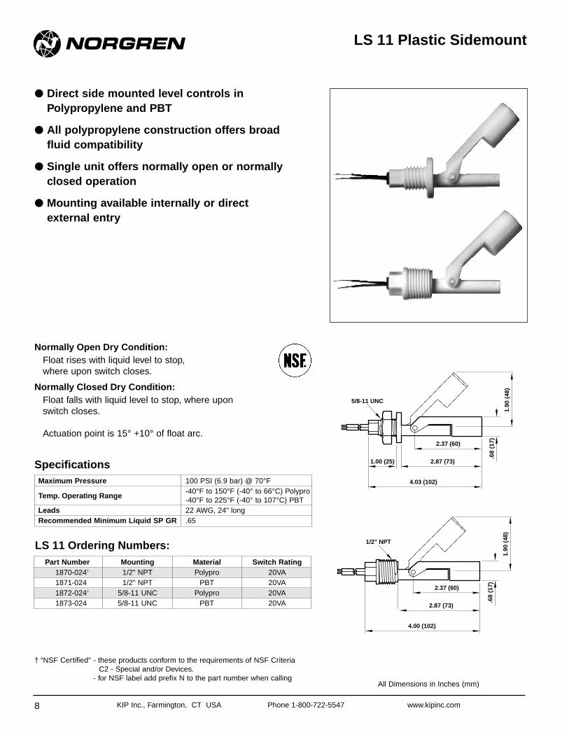
LS 11 Plastic Sidemount
● Direct side mounted level controls inPolypropylene and PBT
● All polypropylene construction offers broad fluid compatibility
● Single unit offers normally open or normallyclosed operation
● Mounting available internally or direct external entry
Normally Open Dry Condition:Float rises with liquid level to stop, where upon switch closes.
Normally Closed Dry Condition:Float falls with liquid level to stop, where upon switch closes.
Actuation point is 15° +10° of float arc.
Maximum Pressure 100 PSI (6.9 bar) @ 70°F
Temp. Operating Range-40°F to 150°F (-40° to 66°C) Polypro-40°F to 225°F (-40° to 107°C) PBT
Leads 22 AWG, 24" longRecommended Minimum Liquid SP GR .65
Part Number Mounting Material Switch Rating1870-024† 1/2" NPT Polypro 20VA1871-024 1/2" NPT PBT 20VA1872-024† 5/8-11 UNC Polypro 20VA1873-024 5/8-11 UNC PBT 20VA
1.90
(48
)
.68
(17)
4.03 (102)
1.00 (25) 2.87 (73)
2.37 (60)
5/8-11 UNC
1.90
(48
)
.68
(17)
4.00 (102)
2.87 (73)
2.37 (60)
1/2" NPT
Specifications
LS 11 Ordering Numbers:
† “NSF Certified” - these products conform to the requirements of NSF Criteria C2 - Special and/or Devices.
- for NSF label add prefix N to the part number when callingAll Dimensions in Inches (mm)

Single Point Levels
9
All Dimensions in Inches (mm)
KIP Inc., Farmington, CT USA Phone 1-800-722-5547 www.kipinc.com
1.00
(25
)A
1.50
(38
)
.85 (22)
1/8 NPT
1/2 Hex
1.00
(25
)
A
1.50
(38
)
1.00 (25)
1/8 NPT
1/2 Hex
Switch Rating SPST 20VAOperating Pressure 1000 PSI Maximum (68.9 bar)Operating Temperature -40° to 300°F (-40 to 149°C)Float Material Teflon®
Other Wetted Materials 300 Series Stainless, EpoxyLeads 22 AWG, 24" longRecommended Minimum Liquid SP GR .75
Part Number Stem Material Switch Rating1275-024 316 SS 20VA N.O. DRY*1276-024 316 SS 20VA N.C. DRY*
Part Stem Float Other SwitchNumber Material Material Wetted Parts Rating0105-024 316 SS Buna N 316 SS 20VA0106-024 Brass Buna N 316 SS 20VA
Maximum Pressure 150 PSI (10.3 bar)Temperature Operating Range -40° to 225°F (-40° to 107°C) in oil
to 180°F (82°C) in waterMounting 1/8" NPTLeads 22 AWG, 24" longRecommended Minimum Liquid SP GR .50
A - actuation point isapproximatelymidway of float travelin liquid with aspecific gravity of1.0.
A - actuation point is approximately midway of floattravel in liquid with a specific gravity of 1.0.
UL RecognizedFile No. E 129277
CSA ApprovedFile No. LR 90981
25 BN Series—Teflon® FloatNorgren Offers Its 25 BN Series with a Spring Biased TEFLON® Float for High Pressure Applications
FEATURES:• Small float design (.850 Dia.) provides flexibility for those tight
spaces• Solid Teflon® float design for pressures up to 1000 PSI• Variety of stem float combinations to meet your technical and
cost requirements
Specifications:
25 BN Series Ordering Numbers:
* UL and CSA switch ratings are 20VA pilot duty rated; 120VAC - 240VAC ® Teflon is a registered trademark of E.I. Dupont De Nemours Co.
25 BN SeriesBuna N General Purpose Single Point Detector
Specifications:
25 BN Series Ordering Numbers:
FEATURES:• Small, compact size• Precise repeatability• Reliable, long-life performance• Highly resistant to shock and vibration• Stem available in 316 SS or Brass

Single Point Levels
10
All Dimensions in Inches (mm)
KIP Inc., Farmington, CT USA Phone 1-800-722-5547 www.kipinc.com
Part Stem / Float Other Wetted SwitchNumber Material Mounting Material Rating1344-001 Brass / Buna Stainless / Epoxy SPST 20VA1344-002 Brass / Buna Stainless / Epoxy SPST 100VA1344-003 304 SS / Buna Stainless / Epoxy SPST 20VA1344-004 304 SS / Buna Stainless / Epoxy SPST 100VA1344-005 304 SS / 316 SS 316 SS SPST 20VA1344-006 304 SS / 316 SS 316 SS SPST 100VA
Maximum Pressure 150 PSI (10.3 bar)Temperature -40°F to 225°F (-40°C to 107°C) in oilOperating Range -40°F to 180°F (-40°C to 82°C) in water
Mounting 1/4" NPTLeads 18 AWG, 36" longRecommended Minimum Liquid SP GR .55
1.88
(48
)
A
2.70
(69
)
1.88 (48)
1/4 NPT
Moisture ResistantShrink Tubing
5/8 Hex
50 BN Moisture Resistant Liquid Level SwitchConstruction Provides Maximum Resistance to Moisture, Condensation or Water.
FEATURES:• Ideal for use in sumps or bilges• Construction can be adapted to other Norgren switches• Dual wall polyolefin shrink tubing resists moisture
Specifications:
Liquid Level Switch Ordering Numbers:
A - actuation point isapproximatelymidway of float travelin liquid with aspecific gravity of1.0.

Single Point Levels
11
All Dimensions in Inches (mm)
KIP Inc., Farmington, CT USA Phone 1-800-722-5547 www.kipinc.com
50 BN Series LargeLarge Size General Purpose Detector
FEATURES:• Large float provides maximum displacement in high viscosity
fluids• Can be easily extended to multiple float arrangement up to 72"
long (see pages 20-21)• Rugged design for heavy duty service
50 BN Series IntermediateIntermediate Size General Purpose Detector
FEATURES:• Highly reliable, yet inexpensive• Compact, narrow displacement• Stem available in 316 SS or Brass• Long operating life
1.75
(45
)
A
2.50
(64
)
1.19 (30)
1/8 NPT
1/2 Hex
1.75
(45
)
A
2.70
(69
)
1.19 (30)
1/4 NPT
5/8 Hex
1.88
(48
)
A
2.75
(69
)
1.88 (48)
1/4 NPT
5/8 Hex
Maximum Pressure 150 PSI (10.3 bar)Temp. Operating Range -40°F to 225°F (-40°C to 107°C) in oil
-40°F to 180°F (-40°C to 82°C) in waterMounting 1/8" NPT - 1/4" NPTLeads 18 AWG, 24" longRecommended Minimum Liquid SP GR .58
Part Stem Float Other SwitchNumber MTG Material Material Wetted Parts Rating0512-024 1/4" 316 SS Buna N 316 SS 100VA0513-024 1/4" Brass Buna N 316 SS 100VA0514-024 1/4" 316 SS Buna N 316 SS 20VA0515-024 1/4" Brass Buna N 316 SS 20VA
OtherPart Stem Float Wetted Switch
Number MTG Material Material Parts Rating0108-024 1/8" 316 SS Buna N 316 SS 100VA0109-024 1/8" Brass Buna N 316 SS 100VA0500-024 1/4" 316 SS Buna N 316 SS 100VA0501-024 1/4" Brass Buna N 316 SS 100VA0502-024 1/8" 316 SS Buna N 316 SS 20VA0503-024 1/8" Brass Buna N 316 SS 20VA0504-024 1/4" 316 SS Buna N 316 SS 20VA0505-024 1/4" Brass Buna N 316 SS 20VA
Maximum Pressure 150 PSI (10.3 bar)Temp. Operating Range -40°F to 225°F (-40°C to 107°C) in oil
-40°F to 180°F (-40°C to 82°C) in waterMounting 1/4" NPTLeads 18 AWG, 24" longRecommended Minimum Liquid SP GR .55
Specifications:
50 BN Series Inter. Ordering Numbers:
A - actuation point isapproximatelymidway of float travelin liquid with aspecific gravity of1.0.
A - actuation point isapproximatelymidway of float travelin liquid with aspecific gravity of1.0.
Specifications:
50 BN Series Large Ordering Numbers:
Single Point Levels
12
All Dimensions in Inches (mm)
KIP Inc., Farmington, CT USA Phone 1-800-722-5547 www.kipinc.com
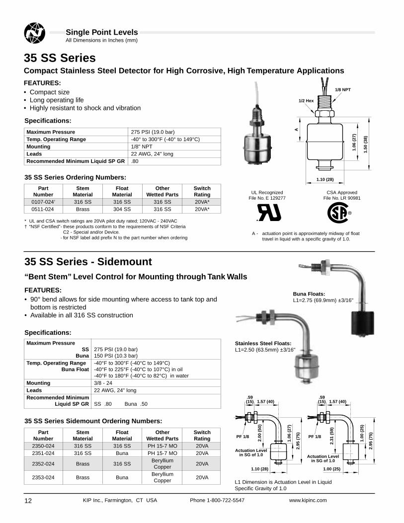
35 SS SeriesCompact Stainless Steel Detector for High Corrosive, High Temperature Applications
FEATURES:• Compact size• Long operating life• Highly resistant to shock and vibration
1.06
(27
)
A
1.50
(38
)
1.10 (28)
1/8 NPT
1/2 Hex
2.95
(75
)
2.00
(50
)
1.06
(27
)
1.10 (28)
1.57 (40).59(15)
PF 1/8
.59(15)
PF 1/8
2.95
(75
)
2.31
(59
)
1.00
(25
)
1.00 (25)
1.57 (40)
Actuation Levelin SG of 1.0
Actuation Levelin SG of 1.0
Maximum Pressure 275 PSI (19.0 bar)Temp. Operating Range -40° to 300°F (-40° to 149°C)Mounting 1/8" NPTLeads 22 AWG, 24" longRecommended Minimum Liquid SP GR .80
Part Stem Float Other SwitchNumber Material Material Wetted Parts Rating
0107-024† 316 SS 316 SS 316 SS 20VA*0511-024 Brass 304 SS 316 SS 20VA*
Maximum Pressure SS 275 PSI (19.0 bar)
Buna 150 PSI (10.3 bar)Temp. Operating Range -40°F to 300°F (-40°C to 149°C)
Buna Float -40°F to 225°F (-40°C to 107°C) in oil-40°F to 180°F (-40°C to 82°C) in water
Mounting 3/8 - 24Leads 22 AWG, 24" longRecommended Minimum
Liquid SP GR SS .80 Buna .50
A - actuation point is approximately midway of floattravel in liquid with a specific gravity of 1.0.
UL RecognizedFile No. E 129277
CSA ApprovedFile No. LR 90981
* UL and CSA switch ratings are 20VA pilot duty rated; 120VAC - 240VAC† “NSF Certified”- these products conform to the requirements of NSF Criteria
C2 - Special and/or Device.- for NSF label add prefix N to the part number when ordering
Specifications:
35 SS Series Ordering Numbers:
35 SS Series - Sidemount“Bent Stem” Level Control for Mounting through Tank Walls
FEATURES:• 90° bend allows for side mounting where access to tank top and
bottom is restricted• Available in all 316 SS construction
Specifications:
35 SS Series Sidemount Ordering Numbers:
L1 Dimension is Actuation Level in Liquid Specific Gravity of 1.0
Stainless Steel Floats:L1=2.50 (63.5mm) ±3/16"
Buna Floats:L1=2.75 (69.9mm) ±3/16"
Part Stem Float Other SwitchNumber Material Material Wetted Parts Rating2350-024 316 SS 316 SS PH 15-7 MO 20VA2351-024 316 SS Buna PH 15-7 MO 20VA
2352-024 Brass 316 SSBeryllium
20VACopper
2353-024 Brass BunaBeryllium
20VACopper
Single Point Levels
13
All Dimensions in Inches (mm)
KIP Inc., Farmington, CT USA Phone 1-800-722-5547 www.kipinc.com
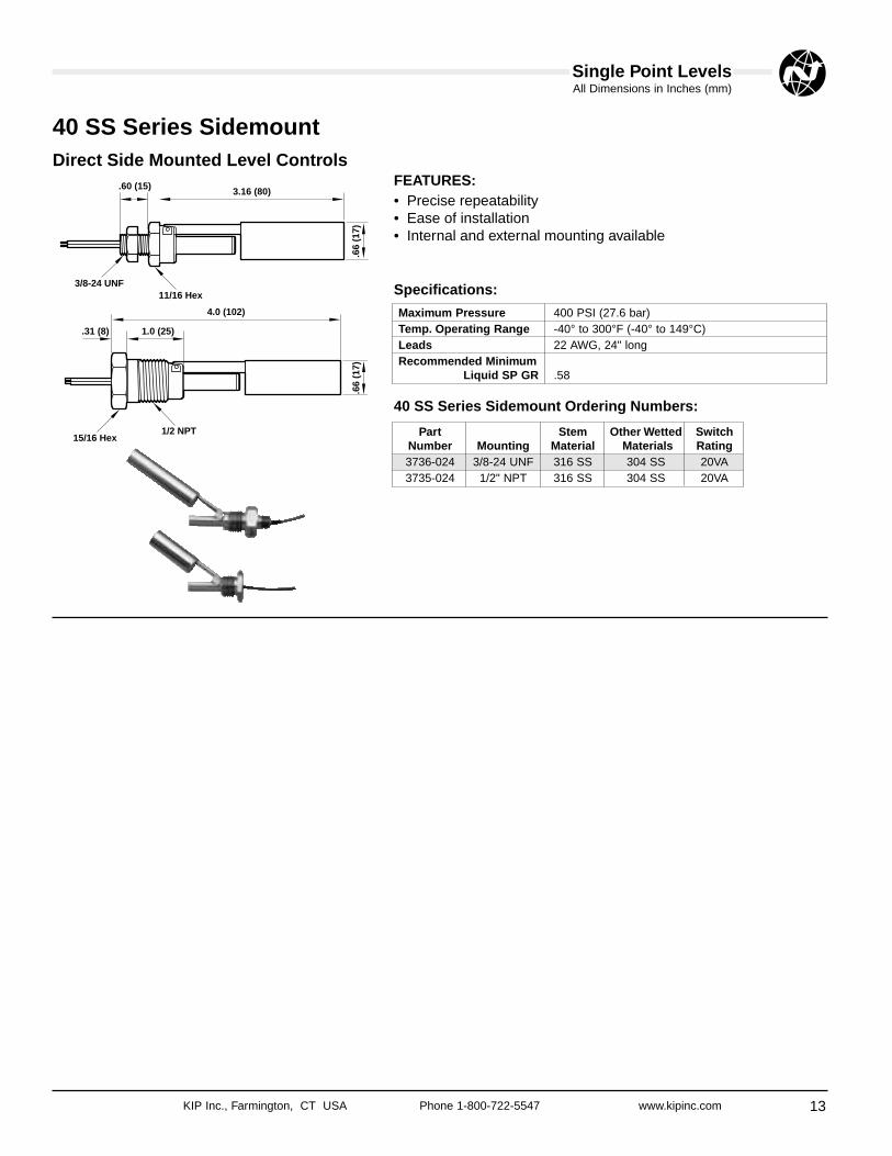
40 SS Series SidemountDirect Side Mounted Level Controls
Maximum Pressure 400 PSI (27.6 bar)Temp. Operating Range -40° to 300°F (-40° to 149°C)Leads 22 AWG, 24" longRecommended Minimum
Liquid SP GR .58
Part Stem Other Wetted SwitchNumber Mounting Material Materials Rating3736-024 3/8-24 UNF 316 SS 304 SS 20VA3735-024 1/2" NPT 316 SS 304 SS 20VA
.66
(17)
.60 (15) 3.16 (80)
3/8-24 UNF11/16 Hex
.66
(17)
1.0 (25).31 (8)
4.0 (102)
15/16 Hex1/2 NPT
Specifications:
40 SS Series Sidemount Ordering Numbers:
FEATURES:• Precise repeatability• Ease of installation• Internal and external mounting available

Single Point Levels
14
All Dimensions in Inches (mm)
KIP Inc., Farmington, CT USA Phone 1-800-722-5547 www.kipinc.com
50 SS SeriesStainless Steel Detector for High Pressure, Corrosive and High Temperature Applications
Features:• All stainless steel wetted surfaces• High resistance to corrosive chemicals• Operates in high temperatures• Operates in high pressure environments
50 SS Series Low Specific GravityBuoyant Float Design for Media with Specific Gravity as Low as .40
Features:• Ideal for use as a high, low or intermediate level alarm in the
storage of propane and butane• Float design can be adapted to Norgren multi-level configuration
for total control• Temperature range of -40°F to 300°F
A
4.50
(11
4)
1/2 NPT
7/8 Hex
3.50 (89)
A
2.70
(69
)
2.00
(51
)
1/4 NPT
5/8 Hex
2.15 (55)
Maximum Pressure 300 PSI (20.7 bar)Temp. Operating Range -40°F to 300°F (-40°C to 149°C)Mounting 1/2" NPTLead Wires 18 AWG, 24" longRecommended Minimum Liquid SP GR .40
Part Stem / Float Other Wetted SwitchNumber Material Materials Rating1348-001 Brass / 316 SS Stainless Steel SPST 20VA1348-002 Brass / 316 SS Stainless Steel SPST 100VA1348-003 Brass / 316 SS Stainless Steel SPDT 20VA1348-004 316 SS / 316 SS Stainless Steel SPST 20VA1348-005 316 SS / 316 SS Stainless Steel SPST 100VA1348-006 316 SS / 316 SS Stainless Steel SPDT 20VA
Maximum Pressure 750 PSI (51.7 bar)Temp. Operating Range -40°F to 300°F (-40°C to 149°C)Mounting 1/4" NPTLeads 18 AWG, 24" longRecommended Minimum Liquid SP GR .73
Part Stem Float Other SwitchNumber Material Material Wetted Parts Rating
0110-024† 316 SS 316 SS 316 SS 100VA0520-024 Brass 316 SS 316 SS 100VA0521-024† 316 SS 316 SS 316 SS 20VA0522-024 Brass 316 SS 316 SS 20VA
† “NSF Certified”- these products conform to the requirements of NSFCriteria C2 - Special and/or Devices.
- for NSF label add prefix N to the part number when ordering.
Specifications:
Low Gravity Float Ordering Numbers:
A - actuation point isapproximately midway offloat travel in liquid with aspecific gravity of 1.0.
Specifications:
50 SS Series Ordering Numbers:
A - actuation point isapproximatelymidway of float travelin liquid with aspecific gravity of1.0.

Single Point Levels
15
All Dimensions in Inches (mm)
KIP Inc., Farmington, CT USA Phone 1-800-722-5547 www.kipinc.com
1.88
(48
)
A
2.50
(64
)
1.38 (35)
1/4 NPT
5/8 Hex
Maximum Pressure 70 PSI (4.8 bar)Temp. Operating Range -40°F to 300°F (-40°C to 149°C)Mounting 1/4" NPTLeads 22 AWG, 24" longRecommended Minimum Liquid SP GR .90
Part Stem Float SwitchNumber Material Material Description Rating0111-024 TFE PFA SPST, NO Dry 20VA*0112-024 TFE PFA SPST, NC Dry 20VA*0113-024 TFE PFA SPDT 3VA
A - actuation point is approximately midway of floattravel in liquid with a specific gravity of 1.0.
UL RecognizedFile No. E 129277
CSA ApprovedFile No. LR 90981
50 TT SeriesTeflon® Level Detector for High Purity, High Corrosive Applications
FEATURES:• All Teflon® wetted surfaces• PFA float for greater resistance to corrosives• Low particulate generation• Chemically inert
Specifications:
50 TT Series Ordering Numbers:
* UL and CSA switch ratings are 20VA pilot duty rated; 120VAC - 240VAC® Teflon is a registered trademark of E.I. Dupont De Nemours Co.

KIP Inc., Farmington, CT USA Phone 1-800-722-5547 www.kipinc.com16
80% Shut-Off Switch forRecovery Refill Cylinders
● Designed specifically for overfill protection ofRefrigerant Recovery Tanks
● Meets rigid UL Requirements for RefrigerantRecovery Equipment
● Switches have been specified to meet thedimensions of the recovery tank manufacturer
● Customize a switch to meet your specific needsincluding multiple floats, various actuation levelsand a variety of wire or connector terminations
Features:• Pressure rating to 400 PSIG (27.6 bar)• Standard for 30# and 50# D.O.T. refrigerant
tanks• Grooved stems keep floats from moving or
falling off• Can be customized for use in other size
cylinders• Available with multiple floats• UL endurance tests performed at 120/60,
240/60, 24/60, 5 VDC, 12 VDC, 24 VDC
CONNECTOR SELECTION DATA
Ground Pin
Master Keyway
Ground Pin is Longer
AMP CONNECTORMATES WITH AMP P/N 206060-1
BRAD HARRISON 3-PINMATES WITH BH-P/N 70303
BRAD HARRISON 2-PINMATES WITH BH-P/N 70023

Single Point Levels
17
All Dimensions in Inches (mm)
KIP Inc., Farmington, CT USA Phone 1-800-722-5547 www.kipinc.com
80% Shut-Off Switch Part Numbering System
3.19
(81
)
1.45
(37
) 5.31
(13
5)
.90 (23)
4 PIN ReceptacleAMP #206153-1
3 PIN ReceptacleBrad Harrison #70212
1-1/16 HEX
3/4-14 NPT
Specifications:
Refrigerant Level Ordering Numbers:
Part “A” “B” Tank Tank PINNumber Dim. Dim. Mfgr. Size Type
0708-0013.19 5.31 (MAN)*,
30#, 50# Brad 3-Pin(81) (135) (WOR)**
0808-0013.19 5.31 (MAN)*,
30#, 50# AMP 3-Pin(81) (135) (WOR)**
1007-0013.19 5.31 (MAN)*,
30#, 50# Brad 3-Pin(81) (135) (WOR)**
1038-0018.40 10.13 (MAN)*,
250# Brad 3-Pin(213) (257) (WOR)**
1047-0016.75 8.88 (MAN)*,
100# Brad 3-Pin(172) (226) (WOR)**
1302-0013.562 5.688
(AMTROL) 26# Brad 3-Pin(90) (144)
1303-0013.875 6.00
(AMTROL) 50# Brad 3-Pin(98) (152)
1546-0018.40 10.13 (MAN)*,
250# AMP 3-Pin(213) (257) (WOR)**
1628-0013.562 5.688
(AMTROL) 26# AMP 3-Pin(90) (144)
1629-0013.875 6.00
(AMTROL) 50# AMP 3-Pin(98) (152)
1632-0016.75 8.88 (MAN)*,
100# AMP 3-Pin(172) (226) (WOR)**
Maximum Pressure 400 PSIG Maximum (27.6 bar)Temperature Operating Range -40° to 221°F SS Float (-40° to 105°C)
Switch Type SPST, Normally Closed DrySwitch Rating 20VAMounting Plug 3/4" NPT
* MAN = Manchester** WOR = Worthington

KIP Inc., Farmington, CT USA Phone 1-800-722-5547 www.kipinc.com18
627 Series MiniatureMulti-Point Level Switches
Norgren Miniature Multi-Point Level controls provide a convenientmethod of customizing your level control with standard lead timesand costs. Our Miniature Multi-Point offers floats as small as .787diameter for those hard to reach areas with up to 5 actuation levelson a single tank entry. Extend your imagination and allow Norgrento build your custom level control when an off the shelf switch won’t do.
Obtain a copy of Norgren Level Switch Inquiry ApplicationSheet and define the general requirements (see page 26):
1. Mounting type.2. Stem and float material.3. Float type, noting temperature ranges, pressure limitations and
minimum recommended specific gravity.4. Switch type, considering voltage and load requirements.5. Wiring group, noting that wiring group I can be utilized with up to 5
levels and wiring group ll can be utilized with 3 levels max.6. Number of actuation points and the distance from the bottom of the
mounting plug- Specify L1 through L5.7. LO-Overall length, which is L1 plus the “C” dimension of your float
selection.8. Switch logic, either normally closed or normally open. When
specifying switch logic, please indicate switch condition when tank isdry.
9. Provide a sketch or drawing along with other pertinent information forproper switch selection.
A = minimum distance to highest level B = minimum distance between levels using two floats C = distance from lowest level to end of unit
USE THE APPLICATION INQUIRY SHEET ON PAGE 26 FOR QUOTATION AND ORDERING
FLOAT NUMBER A DIM. B DIM. C DIM.0118-001 3/4" 1-1/2" 1"0126-002 3/4" 1-1/2" 1"0630-001 3/4" 1-1/2" 1"0564-002 1" 2" 1-1/8"1093-001 3/4" 1-1/2" 1"1415-001 5/8" 1-9/32" 3/4"1416-001 3/4" 1-1/2" 1"2161-001 3/4" 1-1/2" 1"2304-001 3/4" 1-1/2" 1"
L1
L0
L2
L3
L4
L5 A
BC
● Apply any of our Single Point Detectors to your Multi-Point Application
● Up to 48" overall length
● Up to 5 control points
● UL Recognized File #E129277
● CSA Approved File #90981

Multi- Point Levels
19
All Dimensions in Inches (mm)
KIP Inc., Farmington, CT USA Phone 1-800-722-5547 www.kipinc.com
Miniature Multi-Point Design ConsiderationsMounting Styles
WIRINGSPST SWITCHES
Group 1 Group 2Wire #22 AWG #22 AWG
Common Black NoneNO/NC SW Com. NO/NC
L1 Red Red RedL2 Yellow Yellow YellowL3 Blue Blue BlueL4 BrownL5 Orange
SELECTIONCHOICES
TYPE A TYPE B TYPE C TYPE D TYPE E TYPE F
UnitConfiguration
Mounting 1/8" NPT 1/4" NPT 1" NPT 3/4" NPT5/16" 3/8" -24
Tubing THDMaximum 316 SS, Brass up to 48"
Length or PVC up to 24"
0630-001 0118-001 Buna N 0126-002 0564-002 1093-001 1415-001 1416-001316 SS Float (closed cell) Float Polypropylene 304 SS Float Polypro Float Buna Float PBT Float
FLOATCHOICES
Maximum 400 PSI 150 PSI 150 PSI 400 PSI 150 PSI 150 PSI 10 PSIPressure (19 bar) (10.3 bar) (10.3 bar) (27.6 bar) (10.3 bar) (10.3 bar) (.69 bar)Operating -40°F to 300°F (Oil) -40°F to 225°F -40°F to 150°F -40°F to 300°F -40°F to 150°F (Oil) -40°F to 225°F -40°F to 225°F
Temperature (-40°C to 149°C) (-40°C to 107°C) (-40°C to 66°C) (-40°C to 149°C) (-40°C to 66°C) (-40°C to 107°C) (-40°C to 107°C)(Water) (Water)
-40°F to 180°F -40°F to 180°F(-40°C to 82°C) (-40°C to 82°C)
Rec. Min..80 .50 .72 .95 .90 .80 .65Liquid SP GR
2161-001 2304-001 1417-001316 SS Float PVC Float Polypro Float
(Hollow)
FLOATCHOICES
Maximum 275 PSI 50 PSI 10 PSIPressure (19 bar) (3.4 bar) (.69 bar)Operating -40°F to 300°F -40°F to 150°F -40°F to 150°F
Temperature (-40°C to 149°C) (-40°C to 66°C) (-40°C to 66°C)Rec. Min.
.70 .80 .55Liquid SP GR
Stem and 316 SS and Brass up toMounting 48" LengthMaterial PVC up to 24" LengthSwitches SPST, 10VA or 50VA
SPDT, OptionalFloat Stops Brass Units -
Beryllium Copper Grip ringsSS Units - ARMCO PH 15-7 MOPVC Units - PVC316 SS Collar Optional
Leads 22 AWG, 24" long
Specifications:1.
06 (
27)
1.10 (28)
1.00
(25
)
1.00 (25)
1.00
(25
)
1.00 (25)
1.50
(38
)
.90 (23)
1.00
(25
)
.75 (19)
.79
(20)
.79 (20)
1.00
(25
)
1.00 (25)
1.00
(25
)
1.18 (29.8)
1.00
(25
)
1.00 (25)
1.00
(25
)
1.00 (25)
KIP Inc., Farmington, CT USA Phone 1-800-722-5547 www.kipinc.com20
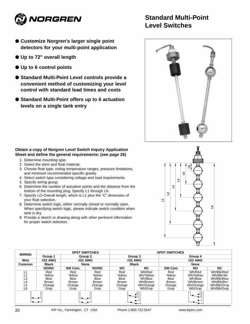
Standard Multi-Point Level Switches
● Customize Norgren's larger single pointdetectors for your multi-point application
● Up to 72" overall length
● Up to 6 control points
● Standard Multi-Point Level controls provide aconvenient method of customizing your levelcontrol with standard lead times and costs
● Standard Multi-Point offers up to 6 actuation levels on a single tank entry
Obtain a copy of Norgren Level Switch Inquiry ApplicationSheet and define the general requirements: (see page 26)
1. Determine mounting type.2. Select the stem and float material.3. Choose float type, noting temperature ranges, pressure limitations,
and minimum recommended specific gravity.4. Select switch type considering voltage and load requirements.5. Specify wiring group.6. Determine the number of actuation points and the distance from the
bottom of the mounting plug. Specify L1 through L6.7. Specify LO-Overall length, which is L1 plus the “C” dimension of
your float selection.8. Determine switch logic, either normally closed or normally open.
When specifying switch logic, please indicate switch condition whentank is dry.
9. Provide a sketch or drawing along with other pertinent informationfor proper switch selection.
L1
L0
L2
L3
L4
L6
L5
WIRINGSPST SWITCHES SPDT SWITCHES
Group 1 Group 2 Group 3 Group 4Wire #22 AWG #22 AWG #22 AWG #22 AWG
Common Black None Black NoneNO/NC SW Com. NO/NC NO NC SW Com NO NC
L1 Red Red Red Red Wh/Red Red Wh/Red Wh/Blk/RedL2 Yellow Yellow Yellow Yellow Wh/Yellow Yellow Wh/Yellow Wh/Blk/YelL3 Blue Blue Blue Blue Wh/Blue Blue Wh/Blue Wh/Blk/BlueL4 Brown Brown Brown Brown Wh/Brown Brown Wh/Brown Wh/Blk/BrnL5 Orange Orange Orange Orange Wh/Orange Orange Wh/Orange Wh/Blk/OrngL6 Gray Gray Gray Gray Wh/Gray Gray Wh/Gray Wh/Blk/Gray

Multi-Point Levels
21
All Dimensions in Inches (mm)
KIP Inc., Farmington, CT USA Phone 1-800-722-5547 www.kipinc.com
Multi-Point Design ConsiderationsMounting StylesSELECTION
CHOICESTYPE 1 TYPE 2 TYPE 3 TYPE 4 TYPE 5 TYPE 6
UnitConfiguration
Mounting 1/2" NPT 1-1/4" NPT 2" NPT3" 150# 1/2" 1-1/2
CS Flange Tubing NPTMax. Length 72" 72" 72" 72" 72" 72"
0127-001 0114-001 0489-001 2305-001316 SS Float Buna N (closed cell) Float Buna N (closed cell) Float PVC Float
FLOATCHOICES
Maximum 750 PSI 150 PSI 150 PSI 15 PSIPressure (51.7 bar) (10.4 bar) (10.4 bar) (1.03 bar)Operating -40°F to 300°F (Oil) -40°F to 225°F (Oil) -40°F to 225°F -40°F to 150°F
Temperature (-40°C to 149°C) (-40°C to 107°C) (-40°C to 107°C) (-40°C to 66°C)(Water) -40°F to 180°F (Water) -40°F to 180°F
(-40°C to 82°C) (-40°C to 82°C)Recommended Min.
.73 .58 .55 .55Liquid SP GR
Stem and 316 SS and Mounting Material Brass up to 72" Length
Switches SPST, 10VA, 50VA or 100VASPDT, Optional
Float Stops Brass Units - Beryllium Copper Grip ringsSS Units - ARMCO PH 15-7 MO316 SS Collar Optional
Leads 22 AWG, 24" long
FLOAT NUMBER A DIM. B DIM. C DIM.0127-001 1-1/2" 3" 2"0114-001 1-1/2" 3" 2"0489-001 1-1/2" 3" 2"2305-001 1-1/2" 3" 2"
Specifications:
2.00
(51
)
2.15 (55)
1.75
(44
)
1.19 (30)
1.88
(48
)
1.88 (48)
1.88
(48
)
1.88 (48)
A = minimum distance to highest levelB = minimum distance between levels using two floatsC = distance from lowest level to end of unit
AC
B
USE THE APPLICATION INQUIRY SHEET ON PAGE 26 FOR QUOTATION AND ORDERING

KIP Inc., Farmington, CT USA Phone 1-800-722-5547 www.kipinc.com22
All Dimensions in Inches (mm)
OTHER OPTIONS:Norgren welcomes the challenge of building your total controlassembly. We can provide custom bottles, assemblies, machining,flanges or other special mounting requirements.
Multi-Point OptionsOPTION A: Junction Boxes with Terminal Strips
J/Box comes pre-wired for levels, complete with wiring diagram
Temperature and Level ControlCombined for Ease of Installation. Convenient Switch-Wiring and Installation of the Level andTemperature Switch Through One Opening.
Specifications:
Liquid Level Switch Ordering Numbers:
1.50
(38
)
1.75
(45
)
4.25
(10
8)
1.19 (30)
Black
Red
Green
1/4 NPT
5/8 Hex
Maximum Pressure 150 PSI (10.3 bar)Operating Temperature -40° to 225°F (-40 to 107°C) in oil
-40° to 180°F (-40 to 82°C) in waterLead Wires No. 18 AWG, 24" longWetted Materials Beryllium Copper, epoxyThermostat Rating 6A/120V 100VA (Non-inductive)
4A/240V 100VA (Non-inductive)Recommended Minimum Liquid SP GR 0.58
Part Stem Float Switch TemperatureNumber Material Material Rating Switch
0777-024 Brass Buna N100VA N.C. Open on 160°FSPST* ±20°F, Increasing
0778-024 Brass Buna N100VA N.O. Close on 160°FSPST* ±20°F, Increasing
1430-024 Brass Buna N20VA N.C. Open on 160°F
SPDT* ±20°F, Increasing
1431-024 Brass Buna N20VA N.O. Close on 160°F
SPDT* ±20°F, Increasing
FEATURES:• Simplifies installation for hydraulic power units• Materials of construction ideal for water, hydrocarbons• Available with a variety of switch configurations and temperature
settings
Multi-Point Levels
NOTE: Other temperature settings and tolerances are available.* Float may be reversed for N.C.

KIP Inc., Farmington, CT USA Phone 1-800-722-5547 www.kipinc.com 23
All Dimensions in Inches (mm)Multi-Point Levels
Level Controls for 55 Gallon DrumsObtain Valuable Information From the Unused 3/4" Bung Fitting In Your Drum By Installing aNorgren High, Low, or High And Low Level Switch.
Easy to install, the Norgren level switch will provide a signal forhigh level alarm to prevent spills, low level signal to warn operatorit’s time to refill, or high and low alarm combined for total control.High and low level signals can either provide input to alarms or canbe combined with a relay or controller to operate valves or pumps.
Units are available in brass mounting and stem material, and Buna-N float for use in hydrocarbons as well as all stainless steelconstruction for more aggressive media.
32 (
81)*
A D
im
.94
(24)
*
.90 (23)*
5/16 (8)*
1-1/16 Hex*
High and Low Level
HighActuation
Level
LowActuation
Level
LowLevel
HighLevel
32 (
81)*
A D
im
C D
im
3/4 NPT
Low Level
ActuationLevel
White
Green
Red
Black
Red
Black
Red
Black
B D
im
.94
(24)
*
PVC Cable6 ft (183cm)
High Level
ActuationLevel
Part Stem / Float SwitchNumber Material Logic Function1295-001 Brass/Buna N.O. Dry High Level1295-002 Brass/Buna N.C. Dry Low Level1295-003 Brass/Buna N.O./N.C High Level/Low Level1295-004 304 SS/304 SS N.O. Dry High Level1295-005 304 SS/304 SS N.C. Dry Low Level1295-006 304 SS/304 SS N.O./N.C High Level/Low Level
Dim Brass/Buna-N Stainless SteelA 31.00 (79cm) 30.38 (77cm)B 2.00 (51) 2.63 (67)C 1.25 (32) 1.50 (38)
Switch Rating SPST 20 VAOperating Pressure 100 PSIG Max (6.9 bar)Operating Temperature -40° to 300°F (-40 to 149°C) - SS Version
-40° to 225°F (-40 to 107°C) - Buna (Oil)-40° to 180°F (-40 to 82°C) - Buna (Water)
Minimum Media Buna N Floats .70Liquid SP GR Stainless .80
Specifications
Level Controls For 55 Gal. Drum Ordering Numbers:
* Other wetted materials:Brass/Buna unit - Beryllium Copper Epoxy: Stainless steel unit - ARMCO PH 15-7 MO grip rings

KIP Inc., Farmington, CT USA Phone 1-800-722-5547 www.kipinc.com24
Norgren Kit
Off the shelf components allow you to assemble acustom level control in minutes. Start with the basicNorgren Kit and add up to 4 Norgren Kit Jr. ‘s tobuild your level control with up to six levels.
● Each starter Norgren Kit contains:1 - Mounting Plug2 - Switch/float assembly2 - 12" extension tubes1 - Tube end fitting3 - Tube unions1 - Tube connector
● Each Norgren Kit Jr. contains:1 - Switch/float assembly1 - Tube union1 - Wire marker label
Part Number Material Mounting Temperature Pressure0525-001 Buna N Float 1-1/4" NPT 0°F to 180°F in water
150 PSI max0525-002 Brass Accessories 2" NPT 0°F to 225°F in oil0525-003 Buna N Float 1-1/4" NPT 0°F to 180°F in water
150 PSI max0525-004 316 SS Accessories 2" NPT 0°F to 225°F in oil
0526-001316 SS Float
2" NPT 0°F to 300°F 500 PSI maxBrass Accessories
0526-002316 SS Float
2" NPT 0°F to 300°F 500 PSI max316 SS Accessories
Part Number Float Material Stem Material Fitting Material Temperature Pressure (Max)0527-001 1-3/16" Dia. Buna N Brass Brass 0°F to 180°F in water
150 PSI0527-002 use with 1-1/4" mtg 316 SS 316 SS 0°F to 225°F in oil0528-001 1-7/8" Dia. Buna N Brass Brass 0°F to 180°F in water
150 PSI0528-002 use with 2" mtg 316 SS 316 SS 0°F to 225°F in oil0529-001 2" Dia. 316 SS Brass Brass
0°F to 300°F 500 PSI0529-002 use with 2" mtg 316 SS 316 SS
Norgren Kit
Norgren Kit Jr.

Assembly Options
25
All Dimensions in Inches (mm)
KIP Inc., Farmington, CT USA Phone 1-800-722-5547 www.kipinc.com
Accessory Norgren Kit Components
J/Box W/TerminalPart Number0523-001
Mounting Plug Tube ConnectorPart Number Mounting Material A DIM0533-001 3/8" NPT Brass 1.750533-002 3/8" NPT 316 SS 1.75
Bulkhead Connector 1/2" TubePart Number Material0536-001 Brass0536-002 316 SS
Union Elbow 1/2" TubePart Number Material0537-001 Brass0537-002 316 SS
Mounting PlugPart Number Mounting Material A DIM0600-001 1-1/4" NPT Brass 1.250600-002 1-1/4" NPT 316 SS 1.250601-001 2" NPT Brass 1.750601-002 2" NPT 316 SS 1.75
Accessory Norgren Kit Components
1/2" NPT with 6" Tube ExtendedPart Number Material0541-001 Brass0541-002 316 SS
1-1/4" NPT with 6" Tube ExtendedPart Number Material0542-001 Brass0542-002 316 SS
2" NPT with 6" Tube ExtendedPart Number Material0543-001 Brass0543-002 316 SS
1/2" Tube Union for connecting tubesand switch assemblyPart Number Material0534-001 Brass0534-002 316 SS
1/2" OD TubingPart Number Length Material0538-001 12" Brass0538-002 12" 316 SS0539-001 24" Brass0539-002 24" 316 SS0540-001 36" Brass0540-002 36" 316 SS
1/2" Tube End Fitting for sealing and switch assemblyPart Number Material0535-001 Brass0535-002 316 SS
Float/Switch AssemblyPart Stem Float Lead
Number Material Material A DIM B DIM Color0530-001 Brass Buna N 4.00 1.19 Red0530-002 Brass Buna N 4.00 1.19 Black0530-003 316 SS Buna N 4.00 1.19 Red0530-004 316 SS Buna N 4.00 1.19 Black0531-001 Brass Buna N 4.25 1.88 Red0531-002 Brass Buna N 4.25 1.88 Black0531-003 316 SS Buna N 4.25 1.88 Red0531-004 316 SS Buna N 4.25 1.88 Black0532-001 Brass 316 SS 4.45 2.10 Red0532-002 Brass 316 SS 4.45 2.10 Black0532-003 316 SS 316 SS 4.45 2.10 Red0532-004 316 SS 316 SS 4.45 2.10 Black
A D
im
B Dim
A D
im
B Dim
A D
im
B Dim
For UseWith AnyMounting
Not ForUse With1-1/4" NPTMounting
Not ForUse With1-1/4" NPTMounting
A
2.58 (66)
1.50
(38
)
1.50 (38)
A
1/2 NPT
2.13 (54)
1.19
(30
)

KIP Inc., Farmington, CT USA Phone 1-800-722-5547 www.kipinc.com26
Level Switch Inquiry Application Sheet
Name ___________________________________________ Company _______________________________________________
Address__________________________________________ City __________________E-mail________________________
State_____________ Zip ______________________ Telephone_________________________ Fax ________________________
Description of application _____________________________________________________________________________________
_________________________________________________________________________________________________________
Immediate Quantity ____________ Prototype Y ______N ______ Estimated Yearly Quantity ________________________________
Submit Sketch of Tank with Switch Location or Competitor Part Number ________________________________________________
_________________________________________________________________________________________________________
MEDIA INFORMATIONLiquid Media _________________________ Specific Gravity ______________________ Viscosity __________________________
Maximum Temp. ______________________ Minimum Temp. ______________________ Operating Temp. ____________________
Maximum Pressure____________________ Operating Pressure ___________________ Tank Material ______________________
MINIATURE MULTI-POINT LEVEL SWITCHMounting: Top_________________ Bottom_________________ Side _________________
Mounting Type: Type A Type B Type C Type D Type E Type F
1/8" NPT__ 1/4" NPT__ 1" NPT__ 3/4" NPT__ 5/16" Tubing__ 3/8-24__ Other ____________
Stem Material: 316 SS_____ Brass_____ PVC_____ Other_______ Float Part Number _______________
STANDARD MULTI-POINT LEVEL SWITCHMounting: Top_________________ Bottom_________________ Side _________________
Mounting Type: Type 1 Type 2 Type 3 Type 4 Type 5 Type 6
1/2" NPT__ 1-1/4" NPT__ 2" NPT__ 3"150# FL(CS)__ 1/2" Tubing__ 1-1/2 NPT__ Other ____________
Stem Material: 316 SS_____ Brass_____ Other_______ Float Part Number_______________________________
SUCTION TUBE LIQUID LEVEL CONTROLMounting Type: Type E __________ Type F __________ Type G___________ Other ___________________________________
Stem Material: PVC ____________Polypropylene ____________ Other___________ Float Part Number __________________
Overall Length Suction Tube: LS _____________________ LSE (Extended) ___________________________
OTHER SELECTION CRITERIAJunction Box __________ Conduit Adapter __________
SWITCH TYPE10VA SPST___________ 50VA SPST__________ 100VA SPST __________ 3VA SPDT ___________ 20VA SPDT ___________
Voltage ___________________ Load Description_____ Wiring Group I _________ Wiring Group II ____________
DIMENSIONAL DATAActuation Level: Inches/MM Indicate N.O. or N.C. with Float in Dry Condition
L6 ________________________ N.O._____________________________ N.C. __________________________
L5 ________________________ N.O._____________________________ N.C. __________________________
L4 ________________________ N.O._____________________________ N.C. __________________________
L3 ________________________ N.O._____________________________ N.C. __________________________
L2 ________________________ N.O._____________________________ N.C. __________________________
L1 ________________________ N.O._____________________________ N.C. __________________________
Length Overall LO ______________
Please Refer to Catalog for Limitation on Numbers of Levels with Each Switch Type and Wiring Group
Application Comments _____________________________________________________________________________________
_________________________________________________________________________________________________________
Copy this page. Fill in the blanks.Fax it to Norgren at (860) 677-4999Call us at (800) 722-5547Date ____/____/____
Assembly Options

KIP Inc., Farmington, CT USA Phone 1-800-722-5547 www.kipinc.com 27
Warning / Warranty
Warning
These products are intended to use inindustrial compressed air systems only. Do notuse these products where pressures andtemperatures can exceed those listed underSpecifications.
Before using these products with fluids otherthan those specified, for non-industrialapplications, life-support systems, or otherapplications not within published specifications,consult Norgren.
Through misuse, age, or malfunction,components used in fluid power systems canfail in various modes. The system designer iswarned to consider the failure modes of allcomponent parts used in fluid power systemsand to provide adequate safeguards to preventpersonal injury or damage to equipment in theevent of such failure modes. System designersmust provide a warning to end users in thesystem instructional manual if protectionagainst a failure mode cannot be adequatelyprovided.
System designers and end users arecautioned to review specific warnings found ininstruction sheets packed and shipped withthese products. System designers should alsoprovide for all OSHA requirements includingTitle 29 CFR 1910.147 Lockout/Tagout.
It should be recognized that warnings arevalid for any product, regardless ofmanufacturer, and are not restricted to productsmanufactured by Norgren. Norgren’s reputationfor product quality and performance is wellestablished. We feel we have the additionalobligation to provide information or warnings tocustomers to assist them in applying ourproducts in a reasonable and safe manner.
WarrantyLimited Warranty, Disclaimer and Limitationof Remedies
Items sold by Norgren are warranted to befree from defects in materials and workmanshipfor a period of one year from the datemanufacture, provided said items are usedaccording to Norgren’s recommended usagesand within Norgen’s specifications. Norgren’sliability is limited to the repair of, or replacementin kind of, at Norgren’s sole option, any itemsproved defective, provided these items arereturned to Norgren prepaid. To confirm date ofpurchase, invoice date or invoice number mustbe furnished; otherwise, date code on productwill be used to determine eligibility for warrantycoverage. The warranties expressed above arein lieu of and exclusive of all other warranties.
There are no other warranties, expressedor implied, except as stated herein. There areno implied warranties of merchantability orfitness for a particular purpose, which arespecifically disclaimed. Norgren’s liability forbreach of warranty as herein stated in theexclusive remedy, and in no event shallNorgren be liable or responsible forincidental or consequential damages, even ifthe possibility of such incidental orconsequential damages has been madeknown to Norgren.
Norgren reserves the right to discontinuemanufacture of any product or change productmaterials, design, or specifications withoutnotice.

Notes
28 KIP Inc., Farmington, CT USA Phone 1-800-722-5547 www.kipinc.com

Notes
29KIP Inc., Farmington, CT USA Phone 1-800-722-5547 www.kipinc.com

Notes
30 KIP Inc., Farmington, CT USA Phone 1-800-722-5547 www.kipinc.com

Notes
31KIP Inc., Farmington, CT USA Phone 1-800-722-5547 www.kipinc.com

Notes
32 KIP Inc., Farmington, CT USA Phone 1-800-722-5547 www.kipinc.com