Liquid Dispensers - SureShot Dispensing · LIQUID DISPENSERS OPERATIONS MANUAL ... containers of...
36
Refrigerated Liquid Dispensers Operations Manual D19006 Rev D
Transcript of Liquid Dispensers - SureShot Dispensing · LIQUID DISPENSERS OPERATIONS MANUAL ... containers of...

Refrigerated Liquid Dispensers
Operations Manual D19006 Rev D

2
AC320FP IntelliShot by SureShot
Portion Controlled
AC220FP FlexoShot by SureShot
SelfServe
AC330PC UniShot by SureShot
Selfserve, portion controlled
AC110PC 1 product AC120PC 1 product AC210PC 2 products AC220PC 2 products AC220FP01 2 products AC230PC 2 products AC320FP 3 products AC330PC 3 products
AC110SS 1 product AC120SS 1 product AC210SS 2 products AC220SS 2 products AC220FP02 2 products AC230SS 2 products
AC330SS 3 products
AC110PC 1 product AC120PC 1 product AC210PC 2 products AC220PC 2 products AC230PC 2 products AC320FP 3 products
AC330PC 3 products
Model Products Function Button Panels Weight Dimensions Capacity AC110PC 1 portion control 1, 3, 4, 5 60 lbs 17¾ x 9½ x 24 1 x 2½ gal (1 x 10 L) AC110SS 1 manual, leveroperated 60 lbs 17¾ x 9½ x 24 1 x 2½ gal (1 x 10 L) AC120PC 1 portion control 1, 3, 4,.5 60 lbs 22 x 12 x 24 1 x 5 gal (1 x 20 L) AC120SS 1 manual, leveroperated 60 lbs 22 x 12 x 24 1 x 5 gal (1 x 20 L) AC210PC 2 portion control 2, 6, 7, 10, 13 75 lbs 17¾ x 9½ x 24 2 x 1½ gal (2 x 6 L) AC210SS 2 manual, leveroperated 75 lbs 17¾ x 9½ x 24 2 x 1½ gal (2 x 6 L) AC220PC 2 portion control 2, 6, 7, 10, 13 75 lbs 22 x 12 x 24 2 x 2½ gal (2 x 10 L) AC220SS 2 manual, leveroperated 75 lbs 22 x 12 x 24 2 x 2½ gal (2 x 10 L) AC220FP01 2 portion control, fill in place 2, 6, 7, 10, 13 75 lbs 22 x 12 x 24 2 x 2½ gal (2 x 10 L) AC220FP02 2 leveloperated, fill in place 75 lbs 22 x 12 x 24 2 x 2½ gal (2 x 10 L) AC230PC 2 portion control 2, 6, 7, 10, 13 80 lbs 22 x 15½ x 24 2 x 2½ gal (2 x 10 L) AC230SS 2 manual, leveroperated 80 lbs 22 x 15½ x 24 2 x 2½ gal (2 x 10 L) AC320FP 3 portion control, fill in place 3, 7, 10, 13 75 lbs 22 x 12 x 24 1 x 2½ gal (1 x 10 L)
2 x 1½ gal (2 x 6 L) AC330PC 3 portion control 3, 7, 10, 13 80 lbs 22 x 15½ x 24 3 x 2½ gal (3 x 10 L) AC330SS 3 manual, leveroperated 80 lbs 22 x 15½ x 24 3 x 2½ gal (3 x 10 L)
NOTES: All Dimensions are in inches, with standard 1” legs installed. Power Supply – all dispensers: 120v AC, 1 ph, 60 Hz, 3 amp Document # D19006 RevD
A.C. Dispensing Equipment Inc. 100 Dispensing Way
Sackville, Nova Scotia Canada B4C 4H2
SureShot Dispensing Systems® Technical Assistance Center
18887779990 or 9028659602 OR [email protected]

3
Table of Contents Dispenser Types 2 Specifications 2 Dispenser Components 4 Overview 5 Safety Precautions 5 Inspection for Damage 6 Uncrating the Dispenser 6 Reshipment 6 Electrical Requirements 6 Servicing – Electrical 6 Servicing – Refrigeration 6 Installation of the Dispenser 7 Clean Before First Use 7 Starting the Dispenser 7 Loading the Dispenser 8
Loading Product Bags 8 Loading Bag in Box 10 Loading Product Tanks 11 Loading Fill in Place Tanks 12 Refill Tanks in Place 12 Reset Fill in Place Dispensers 12
To Remove an Empty Product Tank or Bag 12
OPERATING INSTRUCTIONS Portion Control Dispensers 13
Button Panels 14 Indicator Lights 15
SelfServe Dispensers 16 LCD Display 17
CLEANING Recommended Cleaning Schedule 18 Cleaning – Catch Tray 18 Cleaning – Valve Area 18 Cleaning – Exterior of Dispenser 19 Cleaning – Dispensing Valve PC 20 Cleaning – Dispensing Valve – SS 21 Cleaning – Product Case 22 Cleaning – Product Tanks & Lids 22 Cleaning – Refrigerated Compartment 23 Cleaning – Condenser 23
REFRIGERATION SYSTEM 24 Temperature Control Adjustment 25
Dispenser Running Too Cold 26 Dispenser Running Too Warm 26
RESET To Reset the Power on the Dispenser 27
MAINTENANCE General Maintenance 27
TROUBLESHOOTING No power at the plug 30 Dispenser will not turn on 30 Dispenser will not dispense product 30 Dispenser is not dispensing proper amount
of product 31 Valve is sticky 32 Valve door is broken 32 Dispenser is warm on exterior 32 Dispenser is warm on interior 33 Dispenser is cold on interior 33 Frost buildup in refrigeration
compartment 33 Dispenser is leaking product 34 Dispenser is not level 34 LCD does not come on 34 Red warning light is flashing 35
WARRANTY 36
FIGURES Dispenser Components 4 Loading Product Bags 8 Loading Bag in Box 10 Loading Product Tanks 11 Loading Fill in Place Dispensers 12 FP Dispenser, open, tank cover up 12 Button Panels 1315 LCD Display 17 Valve Assembly 19 Remove and Clean Dispense Valve – PC 20 Remove and Clean Dispense Valve – SS 21 Refrigeration System 24 Circuit Board, B16 25 Circuit Board, C01008 25 Electrical System 28 Wiring Diagram 29

4 DISPENSER COMPONENTS
Dispense Button Dispense Lever
LCD
Reset
Button Panel
Power Indicator
Power Switch Circuit Breaker (not shown)
Dispense Valve
Catch Tray
Valve Cover Splash Guard
5
LIQUID DISPENSERS OPERATIONS MANUAL
Please Read this Manual NOW… Retain it for Future Reference
SureShot Dispensing Systems® Liquid Dispensers provide refrigerated liquids such as cream, whole milk, skim milk, juices, liquid egg and concentrates in automatically controlled portions or in manually selected portions. Our factory has preconfigured your dispenser to deliver product quantities specified by your company. Product selections are made using touch buttons on the front panel. Each button is preset independently to dispense a specified amount of refrigerated product in accurate, portioncontrolled quantities using our unique, stateoftheart microprocessor technology. The product is stored in a sanitary, refrigerated compartment within the dispenser.
IntelliShot – advanced portion control refrigerated liquid dispensers UniShot – selfserve portion control refrigerated liquid dispensers FlexoShot – manual operation refrigerated liquid dispensers
Dispensers are manufactured in a variety of models: (See page 2) PC Portion Controlled to dispense one, two or three products in predetermined quantities SS SelfServe to dispense one, two or three products by levers to deliver quantity desired FP Fill in Place to dispense two or three products in portioncontrolled quantities or self
serve dispensers that may be refilled in place on your shelf
Operating the dispenser is a simple twostep process: For PC and FP Dispensers:
1. Place cup under the product delivery tube. 2. Press buttons for the desired quantity and product.
For SS Dispensers: 1. Place cup under the product delivery tube. 2. Press lever to deliver product quantity you desire.
Safety Precautions • Always plug the dispenser into an approved electrical outlet. • The dispenser includes a microcontroller and must be operated on grounded electrical
wiring at all times. • Unplug the dispenser from its electrical source before servicing. • Do not immerse the dispenser in water. • Observe all safety precautions with this dispenser that you would with any electrical
appliance.

6
INSPECTION FOR DAMAGE When you receive the dispenser, inspect the exterior of the shipping container for damage. Note any damage in detail. Uncrate the dispenser at once (see instructions below). Examine the dispenser for damage. Report any damage to the transportation company immediately. File a claim for damages promptly. Your immediate inspection protects you against loss since SureShot Dispensing Systems® is not responsible for damages incurred during shipment.
UNCRATING THE DISPENSER WARNING: Always lift the dispenser from the bottom. Do not lift the dispenser by the door.
To uncrate: 1. Make sure the box is positioned with the arrow pointing upward. 2. Cut the packing straps at the top of the box. 3. Lift the top tray off the box. 4. Lift the center sleeve off the box. 5. Remove the protective corner inserts from the bottom tray. 6. Lift the dispenser by its bottom out of the tray. Always use two people to lift the
dispenser. 7. Remove the plastic protective covering from the stainless steel exterior of the
dispenser, by peeling it off. To peel, hold the dispenser firmly at the top and peel from top to bottom.
8. Prior to use, read the Operations Manual. Store it for future use. NOTE: The carton top, sleeve, and bottom tray may be stored for future shipping.
RESHIPMENT Packaging for reshipment is done in the reverse order of uncrating. If packaging is not available, it can be purchased locally, or from our factory by request. Any damage occurring in transit of the returned goods caused by improper packaging is not considered a defect covered by Warranty.
ELECTRICAL REQUIREMENTS Be sure the current at the power source receptacle is: 120v AC, single phase, 3 Amp, 60 Hz. The power cord is furnished with a ULapproved 3prong attachment plug. This plug is designed to fit a receptacle with provisions for a grounding stud. The dispenser includes a microcontroller and must be operated on grounded electrical wiring at all times. Failure to do so will void the Warranty.
SERVICING ELECTRICAL Electrical servicing must be carried out by a qualified technician. The Warranty will be null and void if the dispenser is serviced by unqualified personnel. If you need assistance, call the SureShot Dispensing Systems® Technical Assistance Center at 18887779990 or 19028659602.
SERVICING REFRIGERATION Any servicing of the refrigeration system must be carried out by a qualified technician. The Warranty will be null and void if the refrigeration system is serviced by unqualified personnel. If you need assistance, call the SureShot Dispensing Systems® Technical Assistance Center at 18887779990 or 19028659602.

7
INSTALLATION AND LOCATION OF THE DISPENSER
1. Location of Dispenser: • Place the dispenser where it will best serve your operation. • Counters, platforms, or shelves should be strong enough to support the dispenser and full
containers of product. Refer to the minimum weight of your dispenser model on page 2. This is the weight of the empty dispenser.
• Place the dispenser at the appropriate serving height so that people drawing product from the dispenser can operate the buttons as well as easily place and remove cups.
• Leave clear space around the dispenser, approximately 1 inch or 2.5 cm on all sides. • Do not place the dispenser too close to a source of heat or moisture. Allow a minimum 1
inch (2.5 cm) airspace between machines at all times. The performance and efficiency of the refrigeration system will be reduced if the dispenser is placed too close to a heat generating machine, such as a coffeemaker.
• Do not block the vents at the top rear of the dispenser. The vents must be free and open to ensure proper operation of the ventilation system and to prevent overheating and damage to the system.
• The dispenser must be placed on a level surface or leveled by adjusting the legs. The dispenser must be level to dispense accurate quantities and to ensure proper functioning of the refrigeration system.
• Do not remove the legs from the dispenser or allow the dispenser to sit flat on the counter. Airflow and circulation under the machine are essential for the proper operation of the refrigeration system. Make sure the legs at the four corners of the bottom of the dispenser are in place. If one has loosened during shipping, retighten it. Some dispenser models have adjustable legs and these legs are secure even though they may appear to be loose. Removal of the legs automatically voids the Warranty.
CLEAN BEFORE FIRST USE OF THE DISPENSER • Make sure you clean the dispenser thoroughly. See Cleaning Instructions for the Exterior
of the Dispenser and the Dispenser Components on pages 1823. • All dairy tanks and lids must be cleaned before use. See page 22.
WARNING: Before starting the dispenser, make certain that all Installation instructions have been followed and that the dispenser has been sitting upright for a minimum of 3 hours.
STARTING THE DISPENSER To start the dispenser:
1. Plug the power cord into the proper electrical outlet. 2. Turn the Power Switch “ON”. The power switch is located at the lower left of the
dispenser. Make sure the dispenser door is closed. Push one of the product buttons on the front panel and listen to hear the valve open and close. This confirms that the dispenser is operating. The button panel on the front of most models of dispenser has a power LED which glows green when the dispenser is on.
3. Allow the dispenser to run empty for one hour to achieve a cold temperature before placing product containers in the dispenser. The temperature control has been preset at the factory. You can feel the cold temperature by placing your hand on the top or back wall of the refrigeration compartment.
4. If the dispenser does not appear to be getting cold, check to make sure that it is plugged in and that the power source is active. If the dispenser still does not operate, immediately call the SureShot Dispensing Systems® Technical Assistance Center at 18887779990 or 19028659602.

8
LOADING THE DISPENSER
• Ensure the dispenser has achieved proper operating temperature by running empty for one hour before loading product to be dispensed.
• Product being placed inside the refrigeration compartment should be cooler than 41º F or 5ºC. Some jurisdictions require dairy products to be dispensed from original dairyfilled containers. The product may be transferred from the original dairyfilled containers into clean and sanitized tanks to which delivery tubes are attached. The filled tanks are placed in the refrigerated product compartment.
• Sanitize your hands or wear clean gloves to load the dispenser.
SureShot Dispensing Systems® Liquid Dispensers are manufactured with four delivery systems: Bags: The product is supplied in sanitary prepackaged bags with attached delivery
tubes. The bags are placed in product cases that are placed within the refrigerated product compartment.
Bag in Box: The product is supplied in sanitary prepackaged bags in boxes that fit in the refrigerated product compartment.
Tanks: The product may be transferred from the original dairyfilled containers into clean and sanitized tanks to which delivery tubes are attached. The filled tanks are placed in the refrigerated product compartment. Stainless steel and plastic tanks are available.
Fill in Place: Sanitized tanks may be refilled without removing them from the dispenser.
LOADING: Product Bags Sanitize your hands or wear clean gloves to load the dispenser. 1. Place the bagged product in the product case
provided with the dispenser. Make sure the bag fitment is positioned so the product delivery tube is inserted through the opening at the bottom front of the case and is perpendicular to the dispensing valve.
2. Open the door to the refrigerated product compartment.
3. Open the valve door by unscrewing the black knob in a counterclockwise motion to loosen the screw.
4. Insert the product case in the refrigerated product compartment, with the tube facing out to the front.
5. Make sure there are no kinks or twists in the product delivery tube.
6. Remove the polyethylene film covering the product delivery tube.
7. Align the product delivery tube in the central vertical groove of the valve block. Do not pull or stretch the product delivery tube.
8. Close the valve door, making sure the product delivery tube is in the vertical groove and is not kinked or pinched.
Loading Product Bag
Loading Product – tube alignment

9
9. While holding the valve door closed with one hand, tighten the knobscrew in a clockwise motion until the door is snug. Do not over tighten the screw.
10. Close the refrigerated product compartment door.
11. Squeeze the product delivery tube just below the valve with all fingertips.
12. PC Dispensers: While squeezing the tube, press the “small” product quantity button on the front door button panel once only. This will cause the valve to operate once and relieve pressure in the tube. SS Dispensers: While squeezing the tube, hold the lever down to relieve pressure in the tube.
13. Use sharp scissors or a sharp knife to carefully cut the product delivery tube at a 45° angle at a maximum length of 5/8” from the bottom of the valve block. Discard the cut portion of the tube.
Cut Tube
The dispenser is ready for use.

10
LOADING: Bag in Box • Product is supplied in a sanitary prepackaged bag in a box that fits into the refrigerated
product compartment of the dispenser. • Sanitize your hands or wear clean gloves to install the bag in box and delivery tube.
1. Open the door to the refrigerated compartment. 2. Open the valve door by unscrewing the black
knob in a counterclockwise motion to loosen the screw.
3. Load the bag in box dairy product into the refrigerated product compartment on the Product Box Ramp, with the product delivery tube facing out to the front and centered in the dispensing valve.
4. Make sure there are no kinks or twists in the product delivery tube.
5. Align the product delivery tube in the central vertical groove of the valve block. Do not pull or stretch the product delivery tube.
6. Close the valve door, making sure the product delivery tube is in the vertical groove and is not kinked or pinched.
7. While holding the valve door closed with one hand, tighten the knobscrew in a clockwise motion until the door is snug. Do not over tighten the screw.
8. Squeeze the product delivery tube just below the valve with all fingertips.
9. PC Dispensers: While squeezing the tube, press the “small” product quantity button on the front door button panel once only. This will cause the valve to operate once and relieve pressure in the tube. SS Dispensers: While squeezing the tube, hold the lever down to relieve pressure in the tube.
10. Use sharp scissors to carefully cut the product delivery tube at a 45° angle at a maximum length of 5/8” from the bottom of the valve block. Discard the cut portion of the tube.
12. Close the refrigerated product compartment door.
The dispenser is ready for use.

11
LOADING: Product Tanks • All product tanks must be cleaned properly, sanitized with an
approved sanitizing solution according to the manufacturer’s specifications, and airdried before they are loaded into dispensers. Follow cleaning instructions on page 22.
• Tanks are to be loaded into the dispenser with the power switch ON.
• Tanks should be filled with chilled product before they are loaded into the dispenser. Fill to the FULL level with product chilled to 41°F (5°C) or less.
• See page 12 for Fill in Place dispensers.
1. Sanitize your hands or wear clean gloves to install product tank, tank cover, and delivery tube.
2. Install the dispensing tube onto the tank spout. To maintain sanitation, do not cut the tube until you are ready to attach it to the tank. Remove the plastic film covering the tube. Cut the tube smoothly, with no jagged edges. Save the other half of the tube for another tank. Push the cut end of the tube onto the outlet spout at the bottom front of the product tank. Push the tube all the way to the top of the spout. • Attach a new dispensing tube every time the tank is
cleaned. 3. Open the product compartment door. 4. Open the product dispensing valve door by turning the knob
screw counterclockwise. 5. Place the tank and lid in the dispenser, with the product
delivery tube facing to the front. Install the appropriate tank for each product valve.
6. Align the tube in the central vertical groove of the valve block. 7. Close the dispensing valve door, by turning the knob screw in
a clockwise motion until the door is snug. Make sure the tube is in the vertical groove and is not twisted or pinched during installation. Do not over tighten the screw.
8. Carefully cut the product delivery tube at a 45° angle at a maximum length of 5/8” from the bottom of the valve block. Discard the cut portion of the tube.
9. Open the front door of the dispenser and flip open the top access door to gain access to the tank lids.
10. Flip up the tank lid for the tank to be filled. 11. Pour appropriate product into that tank. Fill to the FULL level with product chilled to 41°F /
5°C. or less. 12. Close tank lids. Close the top access door.
The dispenser is ready for use.
12
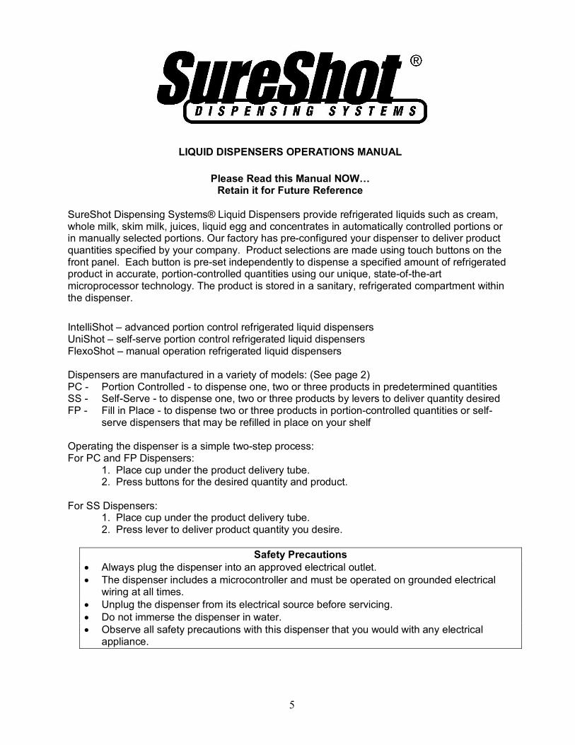
LOADING: Fill in Place tanks
To Fill or Refill Tanks in Place:
1. Open the front door of the dispenser. 2. Flip up the access door on the top of the dispenser to
gain access to the tank lid. 3. Open the lid on the tank to be filled. 4. Fill or Refill the tank to any desired level with product
chilled to 41°F / 5°C or less. 5. Close tank lid. 6. Close the top door. 7. Close the dispenser door. 8. Reset: see below
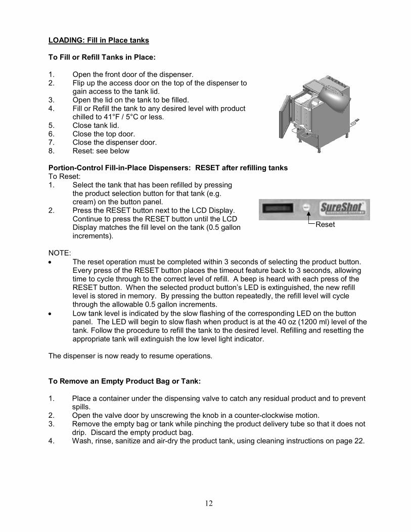
PortionControl FillinPlace Dispensers: RESET after refilling tanks To Reset: 1. Select the tank that has been refilled by pressing
the product selection button for that tank (e.g. cream) on the button panel.
2. Press the RESET button next to the LCD Display. Continue to press the RESET button until the LCD Display matches the fill level on the tank (0.5 gallon increments).
NOTE: • The reset operation must be completed within 3 seconds of selecting the product button.
Every press of the RESET button places the timeout feature back to 3 seconds, allowing time to cycle through to the correct level of refill. A beep is heard with each press of the RESET button. When the selected product button’s LED is extinguished, the new refill level is stored in memory. By pressing the button repeatedly, the refill level will cycle through the allowable 0.5 gallon increments.
• Low tank level is indicated by the slow flashing of the corresponding LED on the button panel. The LED will begin to slow flash when product is at the 40 oz (1200 ml) level of the tank. Follow the procedure to refill the tank to the desired level. Refilling and resetting the appropriate tank will extinguish the low level light indicator.
The dispenser is now ready to resume operations.
To Remove an Empty Product Bag or Tank:
1. Place a container under the dispensing valve to catch any residual product and to prevent spills.
2. Open the valve door by unscrewing the knob in a counterclockwise motion. 3. Remove the empty bag or tank while pinching the product delivery tube so that it does not
drip. Discard the empty product bag. 4. Wash, rinse, sanitize and airdry the product tank, using cleaning instructions on page 22.
Reset

13
OPERATING INSTRUCTIONS – PortionControlled Dispensers
• Make certain all initial SetUp instructions have been followed before operating the dispenser.
• The product and volume to be dispensed are selected by pressing buttons on the Button Panel on the front door of the dispenser.
• Select buttons as required.
To Dispense Product:
1. Place cup under product delivery tube. 2. Press button on bottom row to select product to be dispensed. 3. Press button on middle row to select an optional volume, if required, e.g. for a specialty
drink. 4. Press button on top row to select the product size to be dispensed.
NOTE: • Most Dairy Dispenser models default to coffee settings. • Product selections must be made in this order:
1. Bottom Row – Select Product to be dispensed: e.g. milk, cream, skim 2. Middle Row – Select Specialty Product: these are modifier buttons to dispense
optional volumes that make specialty drinks to customer specifications 3. Top Row – Select Size of portion to be dispensed:
X – extra portion/top up, S – small, M – medium, L – large, XL – extra large
Select Buttons: 1. Bottom – Select Product 2. Middle – Select Specialty 3. Top – Select Size
Button Panel
Size Selection
Power Indicator Light Optional Volume Selection
LED – Red Indicator Light
Product Selection

14
BUTTON PANELS
SureShot Dispensing Systems® dispensers provide product when selection buttons on the front door of the dispenser are pushed.
PortionControlled SelfServe Dispensers:
Push button to deliver 1 product in specified size
Push button to deliver 2 products in specified size
Push button to deliver up to 3 products, e.g. whole milk, cream, skim milk
PortionControlled Dispensers – 1 product:
Push button to dispense one of 3 sizes: small medium large
Push button to dispense one of 4 sizes: small medium large extralarge
PortionControlled Dispensers – 1 product Dual Volumes: Push buttons to dispense one of 4 sizes: 1. Top Row: small medium large extralarge OR Push buttons to dispense one of 4 other sizes 1. Bottom button, then 2. Top Row: small medium large extralarge
PortionControlled Dispensers – 2 products:
1. Bottom Row: Select Product to be dispensed, e.g. whole milk, cream
2. Top Row: small, medium, large, extra large
PortionControlled Dispensers – 2 products – Dual Volumes: 1. Bottom Row: Select Product to be dispensed, e.g. whole
milk, cream 2. OPTIONAL Bottom Center Button for 4 other sizes 3. Top Row: small, medium, large, extra large
PortionControlled Dispensers – 3 products: 1. Bottom Row: Select Product to be dispensed, e.g. whole
milk, skim milk, cream
2. Top Row: small, medium, large, extra large

15
PortionControlled Dispensers – Multiple Combinations:
1. Bottom Row: Select Product, e.g. whole milk, 2% milk, cream
2. Middle Row: add optional volume for specialty products, e.g. latté, cappuccino, espresso
3. Top Row: Select Size: X, S, M, L, XL
PortionControlled Dispensers – Multiple Combinations:
1. Bottom Row: Select Product, e.g. whole milk, skim milk, cream
2. Middle Row: add optional volume for specialty products, e.g. latté, cappuccino, espresso
3. Top Row: Select Size: X, S, M, L, XL
RED INDICATOR LIGHT
The red indicator light (LED) at the top of the dispense buttons indicates which product tank you have selected to dispense product. For dispenser models with Red Indicator Lights, the following options apply:
• When that LED is flashing, the volume in the product tank is getting low and the product will soon need refilling or replacement.
• If that LED is solid red, the tank is out of product, or is locked out for cleaning.
NOTE: • Not all dispensers have LEDs. It is an optional feature and is not available on all
dispensers.
POWER INDICATOR LIGHT
The Power Indicator Light – a red LED labeled “Power” – glows red to indicate that the dispenser power switch is ON. Note: not all dispensers have a Power Indicator Light.

16
OPERATING INSTRUCTIONS – SelfServe DISPENSERS
• Make certain all initial SetUp instructions have been followed before operating the dispenser.
• The product and volume to be dispensed are selected by pressing levers on the front of the dispenser.
• Dispensers deliver one or two or three products.
To Dispense Product:
1. Place cup under product delivery tube for product desired. 2. Press lever down and hold until desired volume is dispensed.
Manually Operated Dispensers (SelfServe):
One product: 1. Place cup under delivery tube 2. Press lever down and hold for desired
amount
Two products: 1. Place cup under desired delivery tube 2. Press lever down and hold for desired
amount
Three products: 1. Place cup under desired delivery tube 2. Press lever down and hold for desired
amount
17
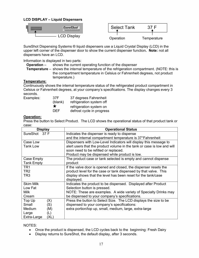
LCD DISPLAY – Liquid Dispensers
LCD Display Operation Temperature
SureShot Dispensing Systems ® liquid dispensers use a Liquid Crystal Display (LCD) in the upper left corner of the dispenser door to show the current dispenser function. Note: not all dispensers have an LCD.
Information is displayed in two parts: Operation – shows the current operating function of the dispenser Temperature – shows the internal temperature of the refrigeration compartment. (NOTE: this is
the compartment temperature in Celsius or Fahrenheit degrees, not product temperature.)
Temperature: Continuously shows the internal temperature status of the refrigerated product compartment in Celsius or Fahrenheit degrees, at your company’s specifications. The display changes every 3 seconds. Examples: 37F 37 degrees Fahrenheit
(blank) refrigeration system off refrigeration system on
DEF defrost cycle in progress Operation: Press the button to Select Product. The LCD shows the operational status of that product tank or case:
Display Operational Status SureShot 37 F Indicates the dispenser is ready to dispense
and the internal compartment temperature is 37°Fahrenheit Case Low Tank Low
Dispensers with LowLevel Indicators will display this message to alert users that the product volume in the tank or case is low and will soon need to be refilled or replaced. Product may be dispensed while product is low.
Case Empty Tank Empty
The product case or tank selected is empty and cannot dispense product
TR1 TR2 TR3
If the valve door is opened and closed, the dispenser resets the product level for the case or tank dispensed by that valve. This display shows that the level has been reset for the tank/case displayed.
Skim Milk Low Fat Milk Cream
Indicates the product to be dispensed. Displayed after Product Selection button is pressed. NOTE: These are examples. A wide variety of Specialty Drinks may be dispensed to your company’s specifications.
Top Up (X) Small (S) Medium (M) Large (L) ExtraLarge (XL)
Press the button to Select Size. The LCD displays the size to be dispensed to your company’s specifications: extra portion/top up, small, medium, large, extralarge
NOTES: • Once the product is dispensed, the LCD cycles back to the beginning: Fresh Dairy • Display returns to SureShot, the default display, after 3 seconds.
Select Tank 37 F

18
CLEANING Do not spray any liquid, such as a cleaner, in or around the valve area.
Liquid could damage electrical components located behind the valve.
RECOMMENDED CLEANING SCHEDULE:
DISPENSER PART FREQUENCY SEE PAGES Catch Tray Daily 18 Splash Guard / Exterior Daily 19 Valve area – Portion Control Daily 18 Valve area – Selfserve Daily 18 Exterior Daily 19 Dispensing valves PC Once a month, or as needed 20 Dispensing valves – Selfserve Once a month, or as needed 21 Product Case Every time valve is cleaned, or as required 22 Product Tank & Lid Every time tank is removed 22 Refrigerated Product Compartment
Every time a new product bag or tank is loaded
23
Condenser Every 6 months 23
CLEANING: Catch Tray
1. Remove the catch tray by lifting it up and off. Note: not all dispensers have a catch tray. 2. Rinse the tray with lukewarm potable water. 3. Place the tray in a hot water wash at a minimum water temperature of 140ºF or 60ºC.
• A good quality general cleaner should be added to the hot wash water at the concentrations recommended by the detergent supplier
4. Wash thoroughly, using a bottle brush to reach all the corners and crevices. • If a dishwasher is available at the location, this step may be carried out by placing the
tray in the dishwasher and washing on the pot cycle. 5. After washing, rinse the tray well with lukewarm potable water. 6. Turn the tray upside down. Air dry.
CLEANING: Valve Area
1. Turn the dispenser OFF. 2. Open the door to the refrigerated product compartment. 3. Thoroughly wipe the area around the valve with a warm, soapy cloth or a sanitized
handiwipe to remove any splashes or product buildup. • Keep the valve area clean for proper sanitation and to ensure proper product delivery. • If the valve area is not clean, the valve may stick and not deliver product accurately. • Clean the valve assembly once a week, when the tank is empty. • Wipe the valve area clean daily.
4. Wipe the area with a damp cloth to remove any soap residue. 5. Air dry thoroughly. 6. Close door to refrigerated product compartment. 7. Turn the dispenser ON.

19
CLEANING: Exterior of Dispenser
NOTE: Do not use any abrasive materials. 1. Use a soft, dry cloth to wipe down the exterior surfaces of the dispenser to maintain the
lustre of the stainless steel finish. 2. Wash the stainless steel exterior surfaces of the dispenser with warm, soapy water. 3. Rinse with warm clear water.
• If the water is hard, wipe the dispenser dry with a soft cloth to prevent water spotting. • Stainless steel polish may be used if it is sprayed on a cloth before the cloth is used to
wipe down the exterior surfaces of the dispenser. • The front of the dispenser should be wiped clean daily.
CLEANING: Valve Area & Valves – PortionControlled Dispensers
NOTE: The diagrams show a 3 product dispenser. The procedures apply to 1, 2, and 3 product models.
• The area around the product delivery valve must be kept clean, for proper sanitation and for the proper delivery of calibrated product amounts. If the valve area is not clean, the valve may stick and not deliver product accurately, or at all.
• The area around the product delivery valve should be wiped clean daily.
It is necessary to remove the valve from the dispenser and take the valve apart to clean it (we recommend once a month or as needed), but it is an easy process if you follow the steps outlined on the following pages.
Valve Assembly
Valve Spring Retainer Valve Spring Valve Plunger Front Panel
Panhead Screw 4x Valve Door – Front
Valve Door Knob Screw Flathead Screw 1x
Hexhead Cap Screw 2x Valve Door Insert Valve Door – Back Reed Switch Wire
Valve Block

20
CLEANING: Remove & Clean Dispensing Valve Assembly – Portion Control Dispensers
NOTES: Prepare a container of warm, soapy water before you take the valve apart for cleaning. Be careful not to dislodge the cable during cleaning.
1. Turn the power to the dispenser OFF. 2. Open the dispenser door to the refrigerated product compartment. 3. Remove the product tanks by following the instructions on page12. 4. Remove the catch tray (if applicable) by lifting it up and off. 5. Remove the 4 panhead screws (+) that secure the front splash panel
(valve cover) in place and carefully remove the panel. It is located below the white plastic valves that hold the product dispensing tubes. It is held in place by 4 Phillipshead screws (+). Thoroughly wash the splash panel.
6. Open the valve door: unscrew the black knob in a counterclockwise motion.
7. Remove the Phillipshead screw at the top of the metal valve insert. Do not misplace the screw. Wipe clean.
8. Remove the 2 Phillipshead screws at the upper corners of the valve block. Do not misplace the screws. Wipe clean.
9. Gently remove the white valve body, using an even force. Hold the valve carefully with one hand so that the thermistor wire will not be broken or damaged. Do not let the valve dangle freely. Hold it in your hands. NOTE: The valve body can only be moved the length of the
thermistor wire, which is located in the left valve. 10. Remove the plunger and spring. Wash, rinse, sanitize, and air dry the
plunger and the spring 11. Wipe the spring cup clean. 12. Clean the white plastic sections of the valve block, using a small
brush with warm, soapy water. Rinse, sanitize, and air dry the white plastic sections of the valve block with the plunger and spring. Air dry thoroughly.
13. Reassemble the spring, the plunger, and the valve body. 14. Align the valve body with the plunger. Move back into place. 15. Replace the 2 Phillipshead screws. Tighten until snug.
Do not overtighten the screws. 16. Replace Phillipshead screw at the top of the metal valve insert. This
screw must fit snugly to ensure proper operation of the refrigeration system. Do not overtighten the screw.
17. Close the valve door. 18. Secure the door by tightening the knobscrew in a clockwise motion
until the door is snug. Do not overtighten the screw. 19. Reinstall 4 Phillipshead screws to secure the front panel in place. 20. Wipe the product compartment clean. 21. Close the refrigerated product compartment door. 22. Turn dispenser ON. 23. Push any “product” button, followed by any “size” button. Listen for
the valve door open and close to ensure that the valve is operating properly.
24. Load new product and dispense.
Step 5
Step 6
Step 7
Step 9
Step 10
Step 13

21
CLEANING: Remove & Clean the Dispensing Valve Assembly – SelfServe Dispensers
NOTES: Prepare a container of warm, soapy water before you take the valve apart for cleaning. Be careful not to dislodge the cable during cleaning.
1. Turn the power to the dispenser OFF. 2. Drain product tanks and remove empty tanks. 3. Open the door to the refrigerated product compartment. 4. Remove the catch tray (if applicable) by lifting it up and off. 5. Remove the 4 panhead screws (+) that secure the front splash
panel/valve cover in place and carefully remove the front splash panel/valve cover. It is located below the white plastic valves that hold the product tubes. It is held in place by 4 Phillipshead screws (+). Thoroughly wash the splash panel.
6. Open the valve door: unscrew the black knob in a counterclockwise motion.
7. Remove the Phillipshead screw which retains the aluminum insert. Do not misplace the screw. Wipe the insert and screw clean.
8. Remove the 2 Phillipshead screws at the upper corners of the valve block. Do not misplace the screws.
9. Remove the white valve body. Hold the valve carefully with one hand so that the thermistor wire will not be broken or damaged. The steel handle comes off with the valve body. NOTE: The valve body can only be moved the length of the
thermistor wire, which is located in the left valve. 10. Remove the plunger tip and spring. Wash, rinse, sanitize, and air dry
the plunger tip and spring. 11. Wipe the spring cup clean. 12. Wash the handle, plunger tip and spring in warm, soapy water.
Rinse with clear water. Dry thoroughly. 13. Clean the white plastic sections of the valve block, using a small
brush with warm, soapy water. Dry thoroughly. 14. Clean the valve door front, valve door back, and insert. 15. Put the spring and plunger back together so that you can reassemble
the valve body. 16. Align the valve body with the plunger. Move back into place. 17. Replace the 2 Phillipshead screws. Tighten until snug. 18. Replace the Phillips head screw at the top of the metal valve insert.
This screw must fit snugly to ensure proper operation of the refrigeration system. Do not overtighten the screw.
19. Close the valve door. 20. Secure the door by tightening the knobscrew in a clockwise motion
until the door is snug. Do not overtighten the screw. 21. Reinstall the 4 Phillipshead screws to secure the front panel in
place. 22. Wipe the product compartment clean. 23. Close the refrigerated product compartment door. 24. Load new product and dispense.
Step 5
Step 7
Step 8
Step 9

22
CLEANING: Product Case
Product cases are units designed to hold the prebagged product. The cases are made of a metal front, back, and bottom, with plastic sides. Cases must be washed by hand according to provincial or state regulations. When washing by hand, a pot brush is recommended. Make sure the case is cleaned each time the valve is cleaned, or more frequently, if required.
To clean the product case: 1. Remove the product case from the refrigerated product compartment of the dispenser. 2. Wash with hot, soapy water or an approved sanitary cleaning product, according to
provincial or state regulations. 3. Rinse with hot, clear water to remove soap residue. 4. Dry thoroughly.
CLEANING: Product Tanks and Lids or Covers
Product tanks and covers are made of either stainless steel or plastic. Tanks and covers may be washed in a dishwasher or by hand according to provincial and state regulations. If washing by hand, a pot brush is recommended.
Product tanks must be washed and sanitized in a dishwasher or by hand every time the tank is removed from the dispenser and placed in the dispenser. Cleaning requirements may be specified by company policy or local regulation. Comply with their specifications.
Tanks for FillinPlace dispensers must be cleaned to your company’s specifications at regular intervals specified by local authority.
To clean the product tank: 1. When the product has run out, remove the tank from the dispenser. Remove the product
delivery tube from the tank. Discard the tube. Rinse the tank, including the cover, with lukewarm potable water.
2. Place the tank and cover in a hot water wash at a minimum water temperature of 140º F or 60º C. • A good quality general cleaner should be added to the hot wash water at the
concentrations recommended by the detergent supplier. Wash thoroughly, using a bottle brush to reach all the corners and crevices. Wash the outlet spout area, using a small bottle brush. • If a dishwasher is available at the location, this step may be carried out by placing the tank
and cover in the dishwasher and washing on the pot cycle. 3. After the tank and cover have been washed, rinse well with lukewarm potable water. 4. Turn the tank and cover upside down.
Air dry. 5. Before refilling the tank with product, sanitize the tank and cover with mild sanitizer such as
chlorine at 100 ppm, or a product recommended by your detergent supplier. Let the tank and cover drain before filling with product. Do not rinse.
6. Just before filling the tank, apply a new white dairy tube to the outlet spout of the tank. 7. The tank may be prefilled before it is required, but the tank and contents must be stored, with
the cover on, in a refrigerator until placed in the dispenser.

23
CLEANING: Refrigerated Product Compartment of Dispenser
Wipe the compartment clean each time a new product bag or tank is loaded. This will remove any condensation that may accumulate within the compartment.
1. Each time a new product bag or tank is loaded, check the refrigerated product compartment for ice buildup. If ice has accumulated in the refrigerated product compartment, gently remove and discard the ice.
2. Wipe the interior down with a soft cloth 3. Dry thoroughly.
CLEANING: The Condenser
Every 6 months, remove the back panel of the dispenser and inspect the condenser. If necessary, clean the condenser using a vacuum. We suggest a vacuum be used to prevent any damage to the condenser coil.
24
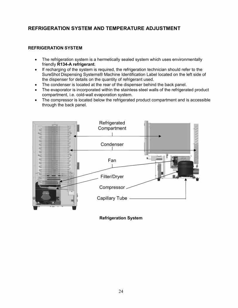
REFRIGERATION SYSTEM AND TEMPERATURE ADJUSTMENT
REFRIGERATION SYSTEM
• The refrigeration system is a hermetically sealed system which uses environmentally friendly R134A refrigerant.
• If recharging of the system is required, the refrigeration technician should refer to the SureShot Dispensing Systems® Machine Identification Label located on the left side of the dispenser for details on the quantity of refrigerant used.
• The condenser is located at the rear of the dispenser behind the back panel. • The evaporator is incorporated within the stainless steel walls of the refrigerated product
compartment, i.e. coldwall evaporation system. • The compressor is located below the refrigerated product compartment and is accessible
through the back panel.
Refrigeration System
Refrigerated Compartment
Condenser
Fan
Filter/Dryer
Compressor
Capillary Tube
25
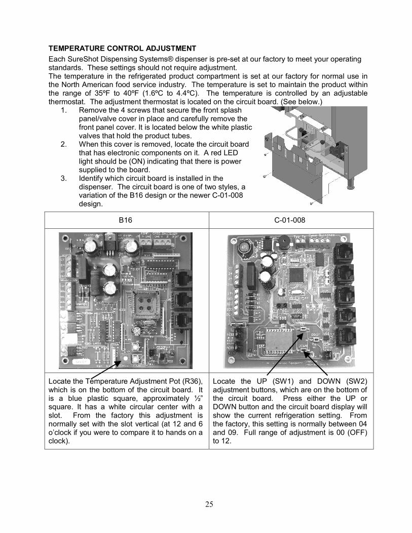
TEMPERATURE CONTROL ADJUSTMENT Each SureShot Dispensing Systems® dispenser is preset at our factory to meet your operating standards. These settings should not require adjustment. The temperature in the refrigerated product compartment is set at our factory for normal use in the North American food service industry. The temperature is set to maintain the product within the range of 35ºF to 40ºF (1.6ºC to 4.4ºC). The temperature is controlled by an adjustable thermostat. The adjustment thermostat is located on the circuit board. (See below.)
1. Remove the 4 screws that secure the front splash panel/valve cover in place and carefully remove the front panel cover. It is located below the white plastic valves that hold the product tubes.
2. When this cover is removed, locate the circuit board that has electronic components on it. A red LED light should be (ON) indicating that there is power supplied to the board.
3. Identify which circuit board is installed in the dispenser. The circuit board is one of two styles, a variation of the B16 design or the newer C01008 design.
B16 C01008
Locate the Temperature Adjustment Pot (R36), which is on the bottom of the circuit board. It is a blue plastic square, approximately ½” square. It has a white circular center with a slot. From the factory this adjustment is normally set with the slot vertical (at 12 and 6 o’clock if you were to compare it to hands on a clock).
Locate the UP (SW1) and DOWN (SW2) adjustment buttons, which are on the bottom of the circuit board. Press either the UP or DOWN button and the circuit board display will show the current refrigeration setting. From the factory, this setting is normally between 04 and 09. Full range of adjustment is 00 (OFF) to 12.

26
Follow the instructions below for adjustments, depending on whether your dispenser is running too cold or too warm.
If The Dispenser Is Running Too Cold:
B16 Circuit Boards C01008 Circuit Boards
To increase the temperature or to make it warmer, turn the white center slot left or counterclockwise 1 hour to 11 o’clock. Allow this adjustment to take effect for 3 hours.
If still not warm enough, adjust the Temperature Adjust to 10 o’clock and repeat the wait time. You can further adjust the temperature to 9 o’clock. Do not adjust further.
To increase the temperature or to make it warmer, press the DOWN button once to recall the current setting, then immediately press the DOWN button a second time to adjust the refrigeration setting warmer by one setting. The circuit board display should indicate this new setting. Allow this adjustment to take effect for 3 hours.
If still not warm enough, repeat this procedure. Do not place the refrigeration setting on 00 because this is the OFF position.
If, after these adjustments are made, your dispenser is still running too cold, please contact the SureShot Dispensing Systems® Technical Assistance Center at 18887779990 or 19028659602 during your 1year warranty period or a qualified Refrigeration Technician after your warranty period has expired.
If The Dispenser Is Running Too Warm:
B16 Circuit Boards C01008 Circuit Boards
To decrease the temperature or to make it colder, turn the white center slot right or clockwise 1 hour to 1 o’clock. Allow this adjustment to take effect for 3 hours.
If still not cold enough, adjust the Temperature Adjust to 2 o’clock and repeat the wait time. You can further adjust the temperature to 3 o’clock. Do not adjust further.
To decrease the temperature or to make it colder, press the UP button once to recall the current setting, then immediately press a second time to adjust the refrigeration setting colder by one setting. The circuit board display should indicate this new setting. Allow this adjustment to take effect for 3 hours.
If still not cold enough, repeat this procedure.
If, after these adjustments are made, your dispenser is still running too warm, please contact the SureShot Dispensing Systems® Technical Assistance Center at 18887779990 or 19028659602 during your 1year warranty period or a qualified Refrigeration Technician after your warranty period has expired.

27
TO RESET THE POWER ON THE DISPENSER: 1. Locate the Power Control ON/OFF switch on the front left of the dispenser. 2. Turn OFF the Power Control ON/OFF switch. 3. Locate the 3 Amp circuit breaker above the Power Control on/off switch. 4. Depress the 3 Amp circuit breaker to make sure it has not popped.
• No white should be showing. If white is showing on the top of the breaker, it is tripped.
• It will make a clicking noise when depressed. 5. Turn back ON the Power Control ON/OFF switch.
MAINTENANCE
General Maintenance • Gently remove ice buildup, if any ice forms. Ice buildup could indicate an improper
temperature setting or an improperly sealed door.
If the dispenser has accumulated ice or frost at the top of the refrigerated product compartment, it is best to remove it by hand during a defrost cycle, which runs automatically and will be indicated on the LCD display panel. Forming ice does not necessarily mean the temperature of the product is too cold.
Ice may be removed during a product change: unplug the dispenser. Leave the door open for about 15 minutes to allow the ice to soften. Remove the ice by hand.
If a temperature adjustment is required, follow the instructions on page 25. If further assistance is required, contact the SureShot Dispensing Systems® Technical Assistance Center at 18887779990 or 19028659602.
• If you have difficulty closing the door, check for ice buildup and remove to ensure proper operation.
• Check the door gaskets, to ensure there are no cuts or gaps. The door must close tightly to ensure proper refrigeration. Check the operation of the fan, being careful not to cut or injure fingers. The fan is located on the right side of the dispenser, behind the front panel (See page 25). If the fan is not operating, call SureShot Dispensing Systems® Technical Assistance Center at 18887779990 or 19028659602 for assistance.
Warning: Keep the dispenser level at all times. Do not tip the dispenser while it is operating. Tipping will damage the compressor and prevent proper operation of the refrigeration system.

28
ELECTRICAL SYSTEM
LCD Display
Power ON/OFF Valve
Circuit Breaker Circuit Board

29
WIRING DIAGRAM:
L Gnd N
P1
Breaker
CB1
Cap S3 Gnd
L M2
N C5
Compressor
C1 Run Capacitor
Blk
Wht
Yel
Org
Org
Grn
Blk Wht
120V 1Phase
Fan
RL1 Relay
ACIN
SOLENOIDS
CT 24 24 GND
+24V SOL1 SOL2 SOL3 REL
TEMP IN GND
CASESWITCHES GND1 2 3
AD1
PCB1
EMI1
TRANS1
Brn
Blu Blu
Org
Brn
Blu
Yel
Blu
Org
Yel
Yel
Red
Red
Com
NO
Quick Connec ts
3 amp Switch
Wiring Diagram: with transformer, refrigeration only shown
L Gnd N
P1
Fan
Power Supp ly
Gnd L N
Door
TH1
BoxThermistor
TH2
TeeThermistor
SO1 SO2 SO3
Switch
SW1
Breaker
CB1
RS1 RS2 RS3
Blk
Blu
Blu
Wht
Yel
Org
Blk
Blk
Wht
Solenoid 1 Solenoid 2 Solenoid 3
Reed Sw.1 Reed Sw.2
Reed Sw.3
120VAC 1Phase
24V2.5A
1Amp
Blk
Blk Red
QuickConnects
Run Capacitor
Yel
Org
Org
Grn
S1 Gnd
S3 S2
Org
Blu
Org
Start Capacitor
ACIN
SOLENOIDS
CT 2424 GND
+24V SOL1 SOL2 SOL3 RE L
TEMP IN GND
CAS ESWITCHES GND1 2 3
AD1
Relay
Wiring Diagram: with power supply, portion control & refrigeration.
30
TROUBLESHOOTING (Refrigerated Liquid Dispensers) PROBLEM ACTION
No power at the plug 1. Have a qualified person check the fuse box or circuit breaker to restore power to the circuit.
2. Check AC outlet to make sure it is 120V AC. 3. Try another working appliance in the outlet to confirm
that the problem is in the outlet.
Dispenser will not turn on
1. Make sure the power cord is plugged in to an active power source.
2. Check the ON/OFF switch (See page 4) on the left side of the dispenser to make sure it is ON.
3. Check to make sure the circuit breaker on the left side of the dispenser has not tripped out. If it has, turn the power switch OFF, reset the circuit breaker by gently pushing it in once to reset it – push in at the top of the breaker until no white is showing. Then, turn the power back ON.
Dispenser will not dispense product
1. Make sure the power cord is plugged in to an active power source.
2. Make sure there is product – milk, cream, etc – in the product compartment.
3. Make sure the product dispensing tube from the product tank is clear of blockage and is properly aligned in the valve with no twists or kinks and is not pinched off.
4. Make sure the valve door is closed. 5. Check the valve area and the valves to make sure they
are clean. NOTE: most problems are caused by dirty, sticky valves. To clean, see pages 18, 20, 21.
6. Turn off the dispenser, wait 10 seconds, then turn the dispenser back on to reset the microcontroller.
7. Check the temperature inside the refrigerated product compartment, to make sure it is within the temperature range of 35ºF. to 40ºF. (1.6ºC to 4.4ºC.) If the dispenser is running cold, it could form ice which may interfere with the flow of product. If a temperature adjustment is required, see page 25. If further assistance is required, contact the SureShot Dispensing Systems® Technical Assistance Center at 18887779990 or 19028659602.
8. Check to ensure that the red power indicator light on the button panel is on. If the power indicator light is not on, check the circuit breaker (See page 4). To check the Circuit Breaker:
Confirm that the Circuit Breaker on the lower left front side of the dispenser has not tripped out. If it has, turn OFF the dispenser, reset the circuit breaker by gently pushing it in once to reset it – push in at the top of the breaker until no white is showing. Then, turn the power back ON.
31
9. Ensure that the program switch located on the lower left side of the circuit board is in the “up” position and that the red LED located next to it is OFF.
10. If there is still no product dispensed, call the SureShot Dispensing Systems® Technical Assistance Center at 18887779990 or 19028659602.
The dispenser is not dispensing the proper amount of product
1. Wrong dairy product is being dispensed – for example, skim is in the cream slot. Review how the dispenser operates.
2. Check to ensure that the system is reset properly. See page 27.
3. Make sure that the product delivery tube is inserted in the valve correctly since incorrect placement can affect product delivery. See page 8.
4. Check to ensure that valve and valve area are clean. 5. Make sure the valve door is not being opened before
the product bag or tank is empty. 6. Make sure product tanks are filled to the required level. 7. Check to see if the refrigeration unit is too cold or too
warm. Ice may interfere with product flow. Check the temperature of the product to ensure that it is approximately 38ºF or 3.3ºC.
Note: Temperature affects the flow of cream and some other liquids. Ice may interfere with flow.
8. Check the refrigeration temperature. Ice may affect product flow. To adjust temperature, see page 25.
9. Check to ensure the system is resetting properly. The volumes to be dispensed are preset electronically in our factory and are reset to the specified amounts automatically each time the front valve door is opened. If your dispenser does not have a reset button (See page 4), follow this procedure to check to ensure the dispenser is resetting: a. make sure no product is spilled during the test by
pinching off the product delivery tube with a pinch clip or fork before you begin.
b. open the valve door by unscrewing the knob in a counterclockwise motion.
c. TR1, TR2, TR3 will be displayed in the LCD when the valve door is opened. A new bag of product must be loaded to ensure proper volumes of product are delivered.
NOTE: If the display does not show TR1, TR2, or TR3 when the valve door is opened, the reed switch is defective and must be replaced. Call the SureShot Dispensing Systems® Technical Assistance Center at 18887779990 or 19028659602 for assistance.
d. ensure the product delivery tube is inserted properly in the valve door.
e. close the valve door securely, by replacing the knob screw. Do not overtighten the screw.

32
f. remove the pinch clip or fork. g. push a dispense button on the front door. If product
is dispensed, the machine has reset and is working properly. If product is not dispensed, call the SureShot Dispensing Systems® Technical Assistance Center at 18887779990 or 19028659602 for assistance.
10. If your dispenser has a reset button, follow the reset procedure on page 12.
Valve is sticky 1. A sticky valve is usually caused by product buildup on the valve. The problem is corrected by cleaning the valve. See Instructions on pages 20, 21.
2. If this doesn't correct the problem, call the SureShot Dispensing Systems® Technical Assistance Center at 18887779990 or 19028659602.
Valve door is broken This indicates the door hinge is broken. The hinge is in two parts: hooks, pins. 1. Hooks: If either or both of the plastic “hooked” areas of
the hinge are missing, the door section valve assembly is broken and must be replaced. Contact SureShot Dispensing Systems® Technical Assistance Center at 18887779990 or 19028659602 for replacements.
2. Pins: If either or both plastic “pins” are missing from the hinge area, the body section of the valve is broken and must be replaced. Contact SureShot Dispensing Systems® Technical Assistance Center at 18887779990 or 19028659602 for replacements.
Dispenser is unusually warm on the exterior
1. Make sure any vents at the top and back of the dispenser are not blocked.
2. Make sure the dispenser is not too close to a heat generating machine, such as a coffeemaker. Allow minimum 1inch airspace between machines at all times.
3. Make sure the dispenser is level on the countertop. 4. Make sure the condenser is not dirty. Remove the back
panel to examine the condenser. If it is dusty or dirty, use a vacuum to clean it.
5. Make sure the fan is operating. Remove the front panel and observe the fan on the right side of the dispenser, in front of the compressor and behind the circuit board. (See page 24) Do a visual inspection only. Be careful not to injure fingers by sticking them in the fan. If the fan is not running, call SureShot Dispensing Systems® Technical Assistance Center at 18887779990 or 19028659602 for service.

33
Dispenser is unusually warm on the interior
1. Check the product temperature, to ensure that the product is properly cooled to approximately 38ºF or 3.3ºC before it is loaded into the dispenser.
2. Check to ensure the vents at the top back of the dispenser are not blocked.
3. Check to make sure the dispenser is not too close to a heatgenerating machine, such as a coffeemaker. Allow minimum 1inch airspace between machines.
4. Check to ensure that the dispenser is level on the countertop at all times.
5. Check to ensure the condenser is not dirty. Remove the back panel to examine the condenser. If it is dusty or dirty, use a vacuum to clean it.
6. The dispenser may be on defrost cycle. The defrost cycle time is 22 minutes in duration. If, after 22 minutes have passed, the dispenser is not cool, reset the defrost cycle by turning OFF the dispenser, waiting 10 seconds, and turning it back ON again. It should become cold after approximately 12 minutes.
7. Check to ensure the fan is operating. Remove the front panel and observe the fan on the right side of the dispenser, in front of the compressor and behind the circuit board. (See page 24) Do a visual inspection only. Be careful not to injure fingers by sticking them in the fan. If the fan is not running, call the SureShot Dispensing Systems® Technical Assistance Center at 18887779990 or 19028659602.
8. If the problem is still not solved, call the SureShot Dispensing Systems® Technical Assistance Center at 18887779990 or 19028659602.
Dispenser is too cold (if dairy product is at least 34° or less for longer than an hour)
1. Check product temperature. If temperature adjustment is required, follow instructions on page 25.
2. Call SureShot Dispensing Systems® Technical Assistance Center at 18887779990 or 19028659602.
Frost build up in the refrigeration compartment
1. Check the temperature inside the refrigerated product compartment, to make sure it is within the temperature range of 35ºF to 40ºF (1.6ºC to 4.4ºC). If the dispenser is running cold, it could form ice.
2. If the dispenser has accumulated ice or frost at the top of the compartment, it is best to remove it during a defrost cycle, which runs automatically and will be indicated on the LCD display panel. Forming ice does not necessarily mean the temperature of the product is too cold. If excessive ice or frost builds up, it should be removed by hand during that defrost cycle.
3. Ice may be removed during a product change: turn off the dispenser. Leave the door open for about 15 minutes to allow the ice to soften. Remove the ice by hand.

34
4. If a temperature adjustment is required, follow the instructions on page 25. If further assistance is required, contact the SureShot Dispensing Systems® Technical Assistance Center at 18887779990 or 19028659602.
Dispenser is leaking product
1. Make sure the valve door is closed securely and its knob screw is tightened properly.
2. Make sure the product dispensing tube is properly aligned in the centre of the delivery valve.
3. Check the tube for cracks or disfiguration. If the tube is cracked or disfigured, replace it. See pages 11 & 12.
4. Check the valve to make sure that it is not dirty. If required, clean the valve following instructions on pages 20 & 21.
5. Check to ensure that the plunger and valve assembly are correct. Ensure that the spring is properly seated in the spring retainer.
Dispenser is not level 1. Check to make sure all four legs at the bottom corners of the dispenser are in place.
2. Tighten any legs that are loose. 3. Make sure the legs are not bent. 4. Replace any bent or missing legs. Replacement legs
may be obtained by contacting SureShot Dispensing Systems® Technical Assistance Center at 18887779990 or 19028659602.
5. Make sure the dispenser is sitting level on the counter. For dispensers with adjustable legs, adjust legs to level dispenser. Use a bubble level to ensure accuracy.
LCD Display on the front door does not come on
Check the red power indicator light on the button panel. If the power indicator light is lit and the LCD Display is not lit, call SureShot Dispensing Systems® Technical Assistance Center at 18887779990 or 19028659602 to replace the LCD Display. If both the power indicator light and the LCD Display are not lit, the circuit breaker has tripped out and must be reset. To Reset the circuit breaker: 1. Turn the power switch OFF. 2. Check the circuit breaker:
Locate the Circuit Breaker on the lower left side of the dispenser.
Gently push the Circuit Breaker in once to reset it – push in at the top of the breaker until no white is showing. Then, turn the power back ON.
3. Turn the power switch ON. 4. If the LCD Display does not come on now, call the
SureShot Dispensing Systems® Technical Assistance Center at 18887779990 or 19028659602.

35
Red warning light at the top of the product selection button is flashing
NOTE: The flashing red light is a warning light to indicate that the volume in the product case or tank is getting low and the product will need to be replaced or refilled soon. A solid red warning light indicates the product has run out and must be refilled of replaced. The light is an optional feature and may not be found on all dispensers. 1. Open the valve door. 2. Replace or refill the product case or tank. See page 11.
The light should stop flashing or go out. 3. If the light continues, call the SureShot Dispensing
Systems® Technical Assistance Center at 18887779990 or 19028659602.
If these instructions do not correct your problem or if you have other problems, contact: SureShot Dispensing Systems® Technical Assistance Center
18887779990 or 19028659602
NOTE: The Product Identification Label on the left side of each dispenser includes the contact telephone number for SureShot Dispensing Systems®. Refer to the Serial Number and the Model Number on the label when calling SureShot Dispensing Systems®. These numbers are crucial to helping us provide prompt and effective service. This will save you time.

USA AND CANADA WARRANTY This dispenser is covered by a one (1) year onsite warranty, unless otherwise specified.
All dispensing equipment manufactured by A.C. Dispensing Equipment Inc. is warranted against defects in materials and workmanship for a period of one (1) year from the date of purchase.
A.C. Dispensing Equipment Inc.'s obligation under this warranty is limited to the repair of defects as outlined by an A.C. Dispensing Equipment Inc. factoryauthorized service agency or one of its subservice agencies.
This Warranty does not apply to installation or problems caused by installation. This Warranty does not apply to normal preventative maintenance, maintenance or adjustments deemed appropriate by A.C. Dispensing Inc.
THIS WARRANTY WILL BE NULL AND VOID IF THE WARRANTY REGISTRATION CARD IS NOT RETURNED TO A.C. DISPENSING EQUIPMENT INC. WITHIN 60 DAYS OF PURCHASE.
This warranty is subject to the following conditions: • This warranty applies to the original owner only and is not assignable. • Only preauthorized service agencies directed by A.C. Dispensing Equipment Inc. are to be utilized. • Should any product fail to function in its intended manner under normal use within the limits defined in this warranty, at the option
of A.C. Dispensing Equipment Inc., such product will be repaired or replaced by A.C. Dispensing Equipment Inc. or its Authorized Service Agency. A.C. Dispensing Equipment Inc. will be responsible only for charges incurred or service performed by its Authorized Service Agencies. The use of other than A.C. Dispensing Equipment Inc. Authorized Service Agencies will void this warranty and A.C. Dispensing Equipment Inc. will not be responsible for such work or any charges associated with such work. The closest A.C. Dispensing Equipment Inc. Authorized Service Agency must be used and must be dispatched by A.C. Dispensing Equipment Inc.
TIME PERIOD: One year on parts and labour, effective from the date of purchase. The Authorized Service Agency may, at its option, require
proof of purchase. Parts replaced under this Warranty are warranted for the unexpired portion of the original product warranty only.
24hour TollFree Service is available at 18887779990 or 19028659602
A service consultant is available to assist you during our normal business hours. All servicerelated issues will be addressed by a return telephone call the next business day.
WARRANTY PROCEDURE: 1. Secure the Serial Number, Model Number and Option Code from the data label located on the outside of the equipment. 2. Call the number provided on the service label on the dispenser. 3. Our Technical Assistance Center staff will discuss the issue with you and, if necessary, dispatch a technician to your location for
repairs. If afterhours or emergency service is required, A.C. Dispensing Equipment Inc. will not be responsible for any additional charges.
4. To order parts, call the service center and the appropriate parts will be sent to your location or that of the servicing agency.
The following conditions are not covered by this Warranty: • Equipment failure related to improper installation, improper utility connection or supply or problems due to ventilation. • Equipment that has not been properly maintained, calibration of controls, adjustments, damage from improper cleaning and
water damage to controls. • Equipment that has not been used in an appropriate manner or has been subject to misuse or misapplication, neglect, abuse,
accident, alteration, negligence, damage during transit, delivery or installation, fire, flood, riot or act of God. • Equipment on which the model number or serial number has been removed or altered.
If the equipment has been changed, altered, modified or repaired by other than a qualified service technician during or after the warranty period, then the manufacturer shall not be liable for any damages to any person or to any property which may result from the use of the equipment thereafter.
This Warranty does not cover services performed at overtime or premium labour rates. Should service be required at times which normally involve overtime or premium labour rates, the owner shall be charged for the difference between normal service rates and such premium rates. A.C. Dispensing Equipment Inc. does not assume any liability for extended delays in replacing or repairing any items beyond its control.
In all cases, the use of other than A.C. Dispensing Equipment Inc. authorized OEM replacement parts will void this Warranty.
This equipment is intended for commercial use only. Warranty is void if equipment is installed in other than commercial applications.
THE FOREGOING WARRANTY IS IN LIEU OF ANY AND ALL OTHER WARRANTIES EXPRESSED OR IMPLIED, INCLUDING ANY IMPLIED WARRANTY OF MERCHANTABILITY OR FITNESS AND CONSTITUTES THE ENTIRE LIABILITY OF A.C. DISPENSING EQUIPMENT INC. IN NO EVENT DOES THE LIMITED WARRANTY EXTEND BEYOND THE TERMS STATED HEREIN.
A.C. Dispensing Equipment Inc. 100 Dispensing Way Lower Sackville
Nova Scotia, Canada B4C 4H2 18887779990 or 19028659602
22/04/2009 www.sureshotdispensing.com