liquid crystalline polymer microstructures High-fidelity ...
15
Subscriber access provided by UNIVERSITY OF MICHIGAN LIBRARY ACS Applied Materials & Interfaces is published by the American Chemical Society. 1155 Sixteenth Street N.W., Washington, DC 20036 Published by American Chemical Society. Copyright © American Chemical Society. However, no copyright claim is made to original U.S. Government works, or works produced by employees of any Commonwealth realm Crown government in the course of their duties. Article High-fidelity replica molding of glassy liquid crystalline polymer microstructures Hangbo Zhao, Jeong Jae Wie, Davor Copic, C. Ryan Oliver, Alvin Orbaek White, Sanha Kim, and Anastasios John Hart ACS Appl. Mater. Interfaces, Just Accepted Manuscript • DOI: 10.1021/acsami.6b00785 • Publication Date (Web): 04 Mar 2016 Downloaded from http://pubs.acs.org on March 4, 2016 Just Accepted “Just Accepted” manuscripts have been peer-reviewed and accepted for publication. They are posted online prior to technical editing, formatting for publication and author proofing. The American Chemical Society provides “Just Accepted” as a free service to the research community to expedite the dissemination of scientific material as soon as possible after acceptance. “Just Accepted” manuscripts appear in full in PDF format accompanied by an HTML abstract. “Just Accepted” manuscripts have been fully peer reviewed, but should not be considered the official version of record. They are accessible to all readers and citable by the Digital Object Identifier (DOI®). “Just Accepted” is an optional service offered to authors. Therefore, the “Just Accepted” Web site may not include all articles that will be published in the journal. After a manuscript is technically edited and formatted, it will be removed from the “Just Accepted” Web site and published as an ASAP article. Note that technical editing may introduce minor changes to the manuscript text and/or graphics which could affect content, and all legal disclaimers and ethical guidelines that apply to the journal pertain. ACS cannot be held responsible for errors or consequences arising from the use of information contained in these “Just Accepted” manuscripts.
Transcript of liquid crystalline polymer microstructures High-fidelity ...
Subscriber access provided by UNIVERSITY OF MICHIGAN LIBRARY
ACS Applied Materials & Interfaces is published by the American Chemical Society.1155 Sixteenth Street N.W., Washington, DC 20036Published by American Chemical Society. Copyright © American Chemical Society.However, no copyright claim is made to original U.S. Government works, or worksproduced by employees of any Commonwealth realm Crown government in the courseof their duties.
Article
High-fidelity replica molding of glassyliquid crystalline polymer microstructuresHangbo Zhao, Jeong Jae Wie, Davor Copic, C. Ryan Oliver,Alvin Orbaek White, Sanha Kim, and Anastasios John Hart
ACS Appl. Mater. Interfaces, Just Accepted Manuscript • DOI: 10.1021/acsami.6b00785 • Publication Date (Web): 04 Mar 2016
Downloaded from http://pubs.acs.org on March 4, 2016
Just Accepted
“Just Accepted” manuscripts have been peer-reviewed and accepted for publication. They are postedonline prior to technical editing, formatting for publication and author proofing. The American ChemicalSociety provides “Just Accepted” as a free service to the research community to expedite thedissemination of scientific material as soon as possible after acceptance. “Just Accepted” manuscriptsappear in full in PDF format accompanied by an HTML abstract. “Just Accepted” manuscripts have beenfully peer reviewed, but should not be considered the official version of record. They are accessible to allreaders and citable by the Digital Object Identifier (DOI®). “Just Accepted” is an optional service offeredto authors. Therefore, the “Just Accepted” Web site may not include all articles that will be publishedin the journal. After a manuscript is technically edited and formatted, it will be removed from the “JustAccepted” Web site and published as an ASAP article. Note that technical editing may introduce minorchanges to the manuscript text and/or graphics which could affect content, and all legal disclaimersand ethical guidelines that apply to the journal pertain. ACS cannot be held responsible for errorsor consequences arising from the use of information contained in these “Just Accepted” manuscripts.
High-fidelity replica molding of glassy liquid crystalline polymer microstructures
Hangbo Zhao
1, §, Jeong Jae Wie
1, 2, §, Davor Copic
3, §, C. Ryan Oliver
1, Alvin Orbaek White
1, Sanha Kim
1,
A. John Hart1,*
1 Department of Mechanical Engineering, Massachusetts Institute of Technology, 77 Massachusetts
Avenue, Cambridge, MA 02139, USA.
2 Department of Polymer Science and Engineering, 100 Inha-ro, Nam-gu, Incheon, 402-751, Republic of
Korea.
3 Department of Mechanical Engineering, University of Michigan, 2350 Hayward Street, Ann Arbor, MI
48109, USA. § These authors contributed equally to this work.
* Corresponding author: [email protected]
ABSTRACT
Liquid crystalline polymers have recently been engineered to exhibit complex macroscopic shape
adaptivity, including optically- and thermally- driven bending, self-sustaining oscillation, torsional
motion, and three dimensional folding. Miniaturization of these novel materials is of great interest for
both fundamental study of processing conditions and for the development of shape-changing micro-
devices. Here, we present a scalable method for high-fidelity replica molding of glassy liquid crystalline
polymer networks (LCNs), by vacuum-assisted replica molding, along with magnetic field-induced
control of the molecular alignment. We find that an oxygen-free environment is essential to establish
high fidelity molding with low surface roughness. Identical arrays of homeotropic and polydomain LCN
microstructures are fabricated to assess the influence of molecular alignment on the elastic modulus (E =
1.48 GPa compared to E = 0.54 GPa), and side view imaging is used to quantify the reversible thermal
actuation of individual LCN micropillars by high-resolution tracking of edge motion. The methods and
results from this study will be synergistic with future advances in liquid crystalline polymer chemistry,
and could enable the scalable manufacturing of stimuli-responsive surfaces for applications including
microfluidics, tunable optics, and surfaces with switchable wetting and adhesion.
KEYWORDS: liquid crystal polymer, microstructures, replica molding, actuation, surfaces
Page 1 of 14
ACS Paragon Plus Environment
ACS Applied Materials & Interfaces
123456789101112131415161718192021222324252627282930313233343536373839404142434445464748495051525354555657585960
1. INTRODUCTION
Liquid crystalline polymers are rapidly emerging as a platform for the design and manufacturing of
stimuli-responsive materials.1 Incorporation of liquid crystalline moieties within crosslinked polymers
2,
along with local and global manipulation of the nematic director, enables liquid crystalline polymers to
exhibit complex macroscopic shape adaptivity. As a result, liquid crystalline polymers have been
fabricated into structures having optically- and thermally- driven bending,3 self-sustaining oscillation,
4
torsional motion,5-8
and three dimensional folding.2
However, while extensive studies of LC materials have been performed at millimeter-scale and larger
dimensions, fewer studies exist on microstructured liquid crystalline polymers.9-17
This is arguably due
to the difficulty of manufacturing high-fidelity features at microscale simultaneously while controlling the
molecular orientation that is critical to maximizing the active properties of the polymer network.
Formation and shaping of liquid crystalline polymers in miniaturized formats is of great interest for
applications including microfluidics, tunable optics, mechanical metamaterials, and surfaces with
switchable wetting and adhesion.
Molding methods are arguably the most suitable and scalable means to bridge this gap, because of the
combination of shape versatility, feature resolution, and surface quality that can be achieved by molding.
While replica molding of microstructures using master templates has been widely applied to conventional
microfabrication polymers, replica molding of liquid crystalline elastomer (LCE) micropillars has
exhibited rather poor fidelity (e.g., edge quality and sharpness), rough surfaces, and limited control of
geometry and aspect ratio.18
In addition, studies of liquid crystalline polymer microstructures have been
primarily focused on generating large strain responses using soft LCEs, while there has not been
extensive study of glassy liquid crystalline polymer network (LCN) microstructures that have higher
stiffness at the expense of lower strain response. In order to advance applications of liquid crystal
network polymers in active surfaces, and to understand how microscale confinement influences network
organization and active behavior, robust fabrication processes for microstructured surfaces are needed for
both LCEs and LCNs.
We report the use of replica molding to fabricate high-fidelity microstructures of a model liquid
crystalline polymer network (LCN). This is enabled using a custom-built apparatus wherein the LCN
microstructures are formed under controlled atmosphere, temperature, light exposure, and magnetic field.
We show that atmosphere control is essential to achieve the high-fidelity replica molding, and
demonstrate that application of the magnetic field during curing establishes homeotropic order and
mechanical anisotropy, which are characterized by polarized microscopy and nanoindentation,
respectively. Finally, we quantify the reversible thermal actuation behavior of homeotropic and
polydomain microstructures using high-resolution optical imaging.
2. METHODS
To facilitate replica molding of LCN microstructures, silicon master microstructures (Fig. 1c, left) of
various cross-sectional shapes with feature sizes ranging from 10 µm to 300 µm and an approximate
height of 80 µm were fabricated by photolithography and deep reactive ion etching (DRIE). Soft
lithography was then employed to cast a PDMS negative mold (cured at 80 °C for 3 hours) from the
silicon microstructures. Prior to casting, the silicon master surface was treated with a hydrophobic coating
(tridecafluoro-1,1,2,2,-tetrahydrooctyl)-trichlorosilane to facilitate separation of the silicon master and the
PDMS.
Page 2 of 14
ACS Paragon Plus Environment
ACS Applied Materials & Interfaces
123456789101112131415161718192021222324252627282930313233343536373839404142434445464748495051525354555657585960
The liquid crystal polymer network (LCN) was synthesized from a mixture of reactive liquid crystalline
monomers 78.5 wt% RM 257 (Merck), 20 wt% 2-azo (BEAM Co.) and 1.5 wt% photoinitiator I-784
(Ciba) via photopolymerization. The chemical structures of the mixture are shown in Figure S1 in the
Supporting Information.
The powders of the above chemicals were mechanically mixed prior to heating on a glass slide placed
onto a hotplate set at 120 °C for ca. 3 minutes. Then the PDMS negative mold (ca. 2 cm x 1 cm) was
placed on top of the molten mixture. The PDMS mold was gently pressed on the molten mixture to
facilitate the filling process. After 2 minutes, the sample was transferred to a preheated (75 °C) stage
(Figure 1b) inside a vacuum chamber (Figure S2). This temperature is slightly above the nematic to
isotropic transition temperature of the mixture used. The temperature and duration of the mixture on the
hotplate for melting are critical process parameters. We found that using a hotplate temperature 120 °C
temperature and/or a time longer than 5 minutes would cause thermal curing of the mixture, which would
undesirably fix the random molecular orientation of the network before alignment and photocuring.
The custom-built LCN curing apparatus was critical to achieve the results reported in this study. The
stage inside the vacuum chamber was composed of a silicon wafer piece with a thin film heater (BK3552,
BIRK) thermally bonded to its backside, attached to a modified section of rectangular fused quartz tube.
The two ends of the silicon piece were clamped in the quartz stage, suspended over a recess, where an
NdFeB rare earth magnet (BX088SH, K&J Magnetics) was optionally placed. The magnetic field is
therefore oriented vertically with a measured strength of approximately 0.4 T, which is critical to
establish homeotropic alignment of the LCNs. After the molten LCN sample was loaded on the stage the
chamber was evacuated to 10 Torr. A degassing step was performed by repeating a venting-pumping
procedure three times. After allowing the sample to equilibrate for 8 minutes at 75 °C, the mixture was
photopolymerized by exposure to a green light emitting diode (LED) source (60 mW/cm2, 540 nm) for 1
hour while keeping the substrate at 75 °C. The sample was then cooled to room temperature and the
microstructured LCN material was manually delaminated from the PDMS mold. For replica molding of
polydomain LCNs, the identical procedure was performed except that the magnet was removed from the
quartz stage.
In addition to LCN microstructures, LCN films were also fabricated by filling glass cells enclosed by two
glass slides separated by micro glass rods (Nippon Electric Glass Co. Ltd), which established the film
thickness. LCN films were utilized for POM, FT-IR, and nanoindentation measurements.
The elastic moduli of polydomain and homeotropic LCNs were measured by nanoindentation (TI900,
Hysitron). A sharp sapphire indenter with 1 µm diameter at the tip was indented on five different
locations of each film to a maximum depth of 500 nm at a 10 nm/s of indentation rate and 3 seconds of
stoppage between loading and unloading. The surface moduli were determined from the unloading curves
by the Oliver-Pharr method.
The optical system used to image thermal actuation of the LCN microstructures comprised a 20X
objective (NT46-145, Edmund Optics) and a 16X zoom tube lens (NT56-219, Edmund Optics), connected
to a high resolution digital camera (Nikon D5100). The LCN sample was placed on a metal ceramic
heater (HT24S, Thorlabs) controlled by a temperature controller (PTC 10, Stanford Research Systems).
Page 3 of 14
ACS Paragon Plus Environment
ACS Applied Materials & Interfaces
123456789101112131415161718192021222324252627282930313233343536373839404142434445464748495051525354555657585960
3. RESULTS
3.1 High fidelity replica molding of LCN microstructures
High-fidelity replica molding of arrays of LCN microstructures was achieved by replica molding. For
this, it was essential to accurately mix and carefully heat the precursor mixture to achieve an amorphous
melt that fills the PDMS mold, followed by photocuring in an oxygen-free environment. For replica
molding under controlled atmosphere, a custom apparatus was constructed as described in the Methods
section. In Figure 1c, we show exemplary arrays of LCN microstructures that were fabricated on glass
substrates using the replica molding technique. These include structures with varied cross-sectional
shapes and smooth vertical sidewalls matching the master template, high aspect ratios (e.g., a small as 10
µm diameter, ca. 80 µm height), and sharp corners (< 2 µm corner radius).
The fidelity of the molding process was evaluated by comparing the height (Dektak XTTM
, Bruker with 2
µm stylus radius) of the silicon master with its LCN replica. A typical line scan result in Figure S3 shows
heights of 80.37 µm and 79.33 µm of the microstructures (an ‘M’ shape) on the silicon master and the
LCN sample, respectively. This small difference in measured heights (1.29%) indicates full filling of the
liquid crystal mixture into the PDMS negative mold.
Moreover, the vacuum environment during the LCN molding process is critical for degassing the molten
monomer mixture and for complete filling of the molten mixture into the microcavities of the PDMS
mold. LCNs prepared by the same procedure without evacuating the chamber resulted in void
formation (Figure 2a) and large surface roughness, due to trapped air bubbles within the LCN mixture. In
Figure 2b, we show a sample that was degassed yet exposed to air during polymerization. Here, the
roughness is much higher near the exposed edge. Degassed samples that were exposed to nitrogen during
polymerization (not shown) retained the high fidelity surfaces of the master mold. Therefore, we
conclude that oxygen exposure is deleterious to the surface quality of the LCN replica, likely due to
oxygen-induced degradation of the polymer at elevated temperature prior to curing. The presence of both
oxygen and moisture can scavenge free radicals, reducing the degree of polymerization and molecular
weight, and causing more defect formation through side reactions. We believe that removal of oxygen is
more important in our case since the processing temperature is as high as 120 °C for homogenization and
75 °C for photopolymerization.
3.2 Control of LCN molecular order
Building from this baseline process, we studied the influence of a magnetic field to control the alignment
of the LCN before and during the curing step, whereby the rod-like mesogens of liquid crystalline
monomers are known to orient along the magnetic field.19
Thus, the average direction of the molecular
long axes in the liquid crystalline network, referred to as the nematic director, can be controlled by the
direction of the external magnetic field. The orientation of the LCN director was characterized by
polarized optical microscopy (POM) (Axioskop 50, Carl Zeiss) at ambient conditions after finishing the
fabrication process.
POM images of LCN films (10 µm thick) and microstructures fabricated with homeotropic and
polydomain order (i.e., with and without the magnet present during the curing step) are compared in
Figure 3a. Polydomain LCN films and micropillar arrays appear bright under crossed polarizers (referred
to as polarizer and analyzer) regardless of sample rotation, indicating the birefringent nature of the
randomly oriented anisotropic liquid crystalline molecules. For homeotropic LCN films and
microstructures the images are dark (Figure S4), regardless of the orientation of the sample under the
Page 4 of 14
ACS Paragon Plus Environment
ACS Applied Materials & Interfaces
123456789101112131415161718192021222324252627282930313233343536373839404142434445464748495051525354555657585960
optics, suggesting molecular alignment orthogonal to the crossed polarizers (parallel to the sample
thickness direction). An SEM image of the microstructures corresponding to these optical images is
shown in Figure S5.
The influence of magnetically-induced alignment is further characterized by comparing the mechanical
properties of polydomain and homeotropic LCNs. Nanoindentation was performed on LCN films (~10
µm thick), as shown in Figure 3. A greater elastic modulus is expected in the parallel direction to the
nematic director in polymer networks while the lowest modulus is indicative of the perpendicular
direction to the nematic director.20
Thus, the homeotropic film, whose director is perpendicular to the film
surface, should exhibit a higher elastic modulus compared to the randomly oriented polydomain film. As
expected, the homogeneous molecular orientation along the applied load resulted in threefold increase in
elastic modulus (1.48 GPa) in comparison with the random molecular orientation of the polydomain film
(0.54 GPa). The ratio of standard deviation to the average provides the coefficient of variation (CV). A
very low CV value (CV=0.03) is measured from the homeotropic film while a relatively large CV
(CV=0.23) value is found from the randomly aligned polydomain film. The identical FT-IR spectra
(Figure S6) confirm the same chemical composition of both homeotropic and polydomain LCNs and
illustrates that different mechanical properties arise solely from molecular alignment.
3.3 Thermal actuation of LCN microstructures
Aligned liquid crystalline polymers have maximum expansion perpendicular to the nematic director and
largest contraction parallel to the nematic director upon heating.21
To investigate this for the molded
microstructures, the temperature-induced actuation response of the LCN microstructures was studied by
in-situ optical imaging as illustrated in Figure 4a. Side-view observation was chosen to enable
observation of the effects of the substrate constraint on the shape change.
Figure 4 demonstrates the thermomechanical strain response of a homeotropic LCN micropillar with a
diameter of ca. 30 µm. Prior to the analysis, the sample was heated from 30 ºC to 160 ºC and then cooled
to 30 ºC to relax residual stress from the curing process. During the first subsequent heating and cooling
cycle, the micropillar expanded in its radial direction and contracted in its axial direction (vertical). This
anisotropic thermal response is concomitant with a decrease in the order of the network at elevated
temperature. 21-23
This thermomechanical actuation is spontaneous upon heating and is fully reversed after cooling. To
demonstrate this, seven heating-cooling cycles were examined by cycling from 30 ºC to 160 ºC. An
automated edge-tracking algorithm was developed (see Supporting Information) to precisely determine
the normalized changes in the pillar height (H ) and diameter (D ) in microstructures. As shown in
Figure 4c and d, the normalized height and diameter values are reversible and repeatable during the
actuation cycles, with an average of 1.5% decrease in the pillar height and 3.1% increase in the pillar
diameter over the seven actuation cycles. The coefficients of thermal expansion (CTE,α ) were calculated
along the pillar axial and radial directions at 160 ºC. For the homeotropic LCN micropillar, the average
CTE parallel to the axial direction, which is also parallel to the molecular director, is -113 ppm/ºC
(negative CTE for contraction) at 160 ºC over the seven cycles. The CTE orthogonal to the director
(parallel to pillar radial direction) is 241 ppm/ºC. These values are close to those of previous reports using
similar crosslinked LCN materials in the form of films. 20-23
The thermomechanical behavior of a polydomain LCN microstructure was also characterized (see Figure
S7). As expected, a relatively isotropic thermal expansion occurred for both height and diameter upon
heating because of the random molecular orientation in the polydomain networks. Here, the increase in
the average normalized height and the diameter is 3.64% and 1.79%, which corresponds to CTE of 280
Page 5 of 14
ACS Paragon Plus Environment
ACS Applied Materials & Interfaces
123456789101112131415161718192021222324252627282930313233343536373839404142434445464748495051525354555657585960
ppm/ºC and 138 ppm/ºC, respectively. The smaller thermal expansion in diameter can be explained by
the substrate constraint, as the heated pillar appears ‘barrel’ shaped in the side view images. Comparing
the thermal actuation results of the homeotropic and the polydomain micropillars, it is clear that
anisotropy in thermal actuation strongly depends on the molecular alignment of the network; the magnetic
field induced homeotropic order in the network leads to contraction parallel to the director and expansion
perpendicular to it.
By the same method, we examined the thermal actuation of higher aspect ratio micropillars, including the
10 µm diameter homeotropic pillar (height = 80 µm; AR = 8) as shown in Figure S8. This pillar
noticeably shrinks in the vertical direction upon heating, as expected. However, due to the smaller scale,
and the related challenge of imaging the structures from the side view while attached to the substrate, it
was difficult to precisely quantify the percent strain. Nevertheless, this measurement verified the stability
of the smaller structures and that their active behavior was preserved.
It is important to note that such highly crosslinked LCN materials do not undergo a nematic to isotropic
transition23
unlike LCEs.9, 24-25
In other words, thermal degradation of the chemical composition occurs
before thermal energy becomes large enough to disturb alignment of liquid crystal into the randomly
oriented state. Hence, thermal actuation of LCN relies on glass transition temperature with concert of
order parameter decreases not complete disappearance of order like TNI. This different actuation
mechanism inherently limits the strain response in LCN chemistry compared to LCEs.
4. DISCUSSION
Despite the high fidelity replica molding and orientation control we have achieved with LCN
microstructures, limitations of this fabrication technique must be noted. First, it is challenging to
fabricate structures with smaller feature size (<10 µm diameter) and very high aspect ratio (> 10), because
of the difficulty of removing the PDMS mold off the LCN sample without damaging the microstructures.
As the aspect ratio of the microstructures becomes greater, it is easier for the adhesion force between the
PDMS mold and the LCN microstructures to exceed the LCN material strength due to the increased
sidewall area relative to the cross-section area of the microstructures. One potential solution is to
chemically treat the PDMS mold to reduce the adhesion between the LCN surfaces and the mold therefore
facilitate demolding. Another limit is that this technique can only be used to make structures with fixed
cross-sectional shapes (structures from extruding 2-D shapes), while complex 3-D structures could be
more attractive for applications of active surfaces. Nevertheless, this technique presents a useful way for
uniform and high fidelity molding of microstructures, together with detailed characterization of how
microstructures influence mechanical responses. Moreover, the method could be extended to other
chemistries such as for liquid crystal elastomers (LCEs) and provides a general approach for
micromolding of soft materials in combination with both photo- and thermally-controlled curing. With
delicate molecular engineering26
along with scalable shaping techniques, it should be possible to select the
stress and strain response of active microdevices and surfaces based on LCEs and/or LCNs.
Page 6 of 14
ACS Paragon Plus Environment
ACS Applied Materials & Interfaces
123456789101112131415161718192021222324252627282930313233343536373839404142434445464748495051525354555657585960
5. CONCLUSION
In summary, we have presented a scalable replica molding method for LCN microstructures,
demonstrating control of the molecular order within the network along with high-fidelity shape control.
A nearly identical match is found between the silicon master mold and the LCN microstructures, via the
PDMS negative template. The custom built apparatus enables identification of the key features for such
process control: vacuum degassing of the molten precursor upon mold infiltration, removal of oxygen
from the curing atmosphere, and application of magnetic field and controlled temperature to achieve the
final structures. In addition, optical side view imaging enables quantification of the actuation while the
structures remain attached to the substrate, which is a critical capability for further work on LC-based
active surfaces. Advances in the shape diversity of replica molding using complex microfabricated molds,
and optimization of the chemistry to achieve further engineered mechanical response, may potentially
enable such surfaces to achieve dynamic modulation of properties such as adhesion, light manipulation,
and wetting.
6. ACKNOWLEDGEMENTS
Financial support was provided by the National Institutes of Health (1R21HL114011-01A1) and the Air
Force Office of Scientific Research Young Investigator Program (FA9550-11-1-0089). The silicon master
molds were fabricated at the Lurie Nanofabrication Facility (LNF) at the University of Michigan.
Electron microscopy, polarized optical microscopy, surface profilometry and FT-IR were performed at
the MIT Center for Materials Science and Engineering (CMSE). Nanoindentation was performed at the
MIT NanoMechanical Technology Laboratory (Nanolab). We thank Timothy J. White at the Air Force
Research Laboratory for supplying chemicals and for valuable discussions.
7. REFERENCES
(1) White, T. J.; Broer, D. J. Programmable and Adaptive Mechanics with Liquid Crystal
Polymer Networks and Elastomers. Nat. Mater. 2015, 14, 1087-1098.
(2) Ware, T. H.; McConney, M. E.; Wie, J. J.; Tondiglia, V. P.; White, T. J. Voxelated Liquid
Crystal Elastomers. Science 2015, 347, 982-984.
(3) Yu, Y.; Nakano, M.; Ikeda, T. Photomechanics: Directed Bending of a Polymer Film by
Light. Nature 2003, 425, 145-145.
(4) White, T. J.; Tabiryan, N. V.; Serak, S. V.; Hrozhyk, U. A.; Tondiglia, V. P.; Koerner, H.;
Vaia, R. A.; Bunning, T. J. A High Frequency Photodriven Polymer Oscillator. Soft Matter 2008,
4, 1796-1798.
(5) Sawa, Y.; Ye, F.; Urayama, K.; Takigawa, T.; Gimenez-Pinto, V.; Selinger, R. L. B.;
Selinger, J. V. Shape Selection of Twist-Nematic-Elastomer Ribbons. Proc. Natl. Acad. Sci.
U.S.A. 2011, 108, 6364-6368.
(6) Lee, K. M.; Bunning, T. J.; White, T. J. Autonomous, Hands-Free Shape Memory in Glassy,
Liquid Crystalline Polymer Networks. Adv. Mater. 2012, 24, 2839-2843.
(7) Wie, J. J.; Lee, K. M.; Smith, M. L.; Vaia, R. A.; White, T. J. Torsional Mechanical
Responses in Azobenzene Functionalized Liquid Crystalline Polymer Networks. Soft Matter
2013, 9, 9303-9310.
Page 7 of 14
ACS Paragon Plus Environment
ACS Applied Materials & Interfaces
123456789101112131415161718192021222324252627282930313233343536373839404142434445464748495051525354555657585960
(8) Iamsaard, S.; Asshoff, S. J.; Matt, B.; Kudernac, T.; Cornelissen, J. J. L. M.; Fletcher, S. P.;
Katsonis, N. Conversion of Light into Macroscopic Helical Motion. Nat. Chem. 2014, 6, 229-235.
(9) Buguin, A.; Li, M.-H.; Silberzan, P.; Ladoux, B.; Keller, P. Micro-Actuators: When
Artificial Muscles Made of Nematic Liquid Crystal Elastomers Meet Soft Lithography. J. Am.
Chem. Soc. 2006, 128, 1088-1089.
(10) van Oosten, C. L.; Bastiaansen, C. W. M.; Broer, D. J. Printed Artificial Cilia from Liquid-
Crystal Network Actuators Modularly Driven by Light. Nat. Mater. 2009, 8, 677-682.
(11) Ohm, C.; Kapernaum, N.; Nonnenmacher, D.; Giesselmann, F.; Serra, C.; Zentel, R.
Microfluidic Synthesis of Highly Shape-Anisotropic Particles from Liquid Crystalline
Elastomers with Defined Director Field Configurations. J. Am. Chem. Soc. 2011, 133, 5305-5311.
(12) Yan, Z.; Ji, X.; Wu, W.; Wei, J.; Yu, Y. Light-Switchable Behavior of a Microarray of
Azobenzene Liquid Crystal Polymer Induced by Photodeformation. Macromol. Rapid Commun.
2012, 33, 1362-1367.
(13) Wei, R.; Zho, L.; He, Y.; Wang, X.; Keller, P. Effect of Molecular Parameters on
Thermomechanical Behavior of Side-on Nematic Liquid Crystal Elastomers. Polymer 2013, 54,
5321-5329.
(14) Wu, Z. L.; Wei, R.; Buguin, A.; Taulemesse, J. M.; Le Moigne, N.; Bergeret, A.; Wang, X.;
Keller, P. Stimuli-Responsive Topological Change of Microstructured Surfaces and the Resultant
Variations of Wetting Properties. ACS Appl. Mater. Interfaces 2013, 5, 7485-7491.
(15) Liu, X.; Wei, R.; Hoang, P. T.; Wang, X.; Liu, T.; Keller, P. Reversible and Rapid Laser
Actuation of Liquid Crystalline Elastomer Micropillars with Inclusion of Gold Nanoparticles.
Adv. Funct. Mater. 2015, 25, 3022-3032.
(16) Cui, J.; Drotlef, D.-M.; Larraza, I.; Fernandez-Blazquez, J. P.; Boesel, L. F.; Ohm, C.;
Mezger, M.; Zentel, R.; del Campo, A. Bioinspired Actuated Adhesive Patterns of Liquid
Crystalline Elastomers. Adv. Mater. 2012, 24, 4601-4604.
(17) Torras, N.; Zinoviev, K. E.; Esteve, J.; Sanchez-Ferrer, A. Liquid-Crystalline Elastomer
Micropillar Array for Haptic Actuation. J. Mater. Chem. C 2013, 1, 5183-5190.
(18) Wu, Z. L.; Buguin, A.; Yang, H.; Taulemesse, J.-M.; Le Moigne, N.; Bergeret, A.; Wang,
X.; Keller, P. Microstructured Nematic Liquid Crystalline Elastomer Surfaces with Switchable
Wetting Properties. Adv. Funct. Mater. 2013, 23, 3070-3076.
(19) de Gennes, P. G.; Prost, J. The Physics of Liquid Crystals. Oxford University Press: New
York, 1995; Chapter 3, pp 117-118.
(20) van Oosten, C. L.; Harris, K. D.; Bastiaansen, C. W.; Broer, D. J. Glassy Photomechanical
Liquid-Crystal Network Actuators for Microscale Devices. Eur. Phys. J. E. Soft Matter 2007, 23,
329-336.
(21) Mol, G. N.; Harris, K. D.; Bastiaansen, C. W. M.; Broer, D. J. Thermo-Mechanical
Responses of Liquid-Crystal Networks with a Splayed Molecular Organization. Adv. Funct.
Mater. 2005, 15, 1155-1159.
(22) Broer, D. J.; Mol, G. N. Anisotropic Thermal-Expansion of Densely Cross-Linked Oriented
Polymer Networks. Polym. Eng. Sci. 1991, 31, 625-631.
(23) Wie, J. J.; Lee, K. M.; Ware, T. H.; White, T. J. Twists and Turns in Glassy, Liquid
Crystalline Polymer Networks. Macromolecules 2015, 48, 1087-1092.
(24) Warner, M.; Terentjev, E. M. Liquid Crystal Elastomers. Oxford University Press: New
York, 2003; Chapter 2, pp 15-20.
(25) deGennes, P. G.; Hebert, M.; Kant, R. Artificial Muscles Based on Nematic Gels. Macromol.
Symp. 1997, 113, 39-49.
Page 8 of 14
ACS Paragon Plus Environment
ACS Applied Materials & Interfaces
123456789101112131415161718192021222324252627282930313233343536373839404142434445464748495051525354555657585960
(26) Wie, J. J.; Wang, D. H.; Lee, K. M.; Tan, L.-S.; White, T. J. Molecular Engineering of
Azobenzene-Functionalized Polyimides to Enhance Both Photomechanical Work and Motion.
Chem. Mater. 2014, 26, 5223-5230.
Page 9 of 14
ACS Paragon Plus Environment
ACS Applied Materials & Interfaces
123456789101112131415161718192021222324252627282930313233343536373839404142434445464748495051525354555657585960
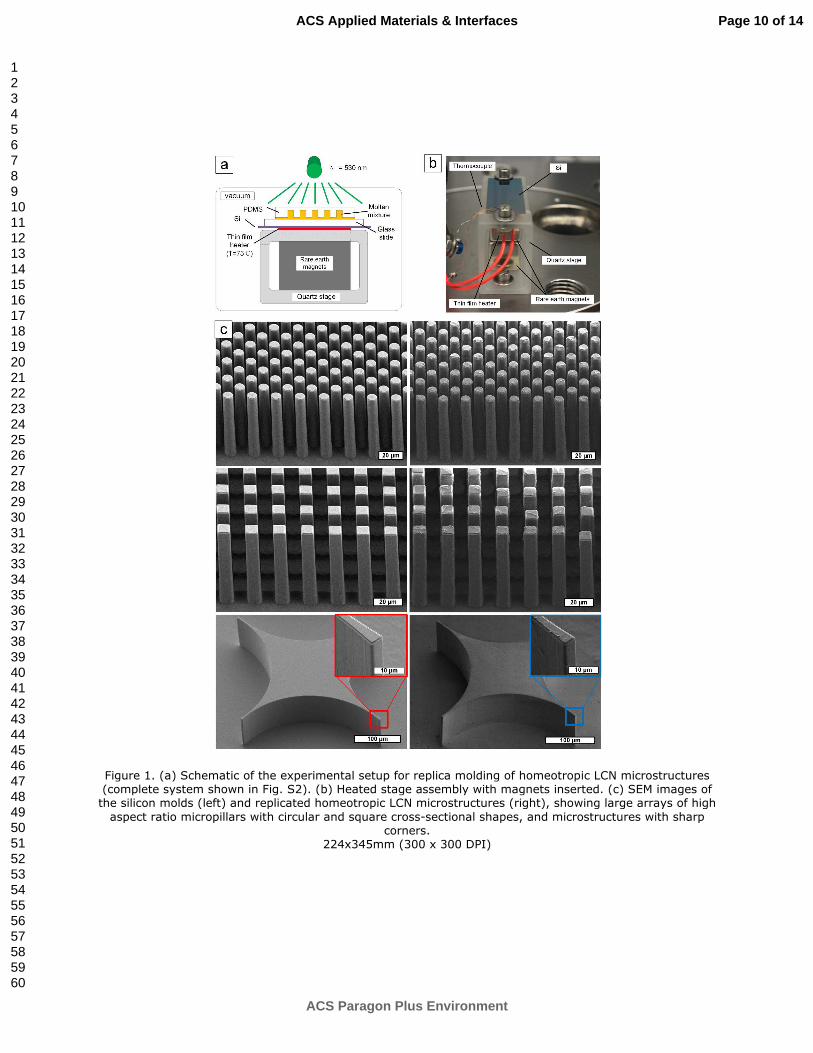
Figure 1. (a) Schematic of the experimental setup for replica molding of homeotropic LCN microstructures (complete system shown in Fig. S2). (b) Heated stage assembly with magnets inserted. (c) SEM images of the silicon molds (left) and replicated homeotropic LCN microstructures (right), showing large arrays of high
aspect ratio micropillars with circular and square cross-sectional shapes, and microstructures with sharp corners.
224x345mm (300 x 300 DPI)
Page 10 of 14
ACS Paragon Plus Environment
ACS Applied Materials & Interfaces
123456789101112131415161718192021222324252627282930313233343536373839404142434445464748495051525354555657585960
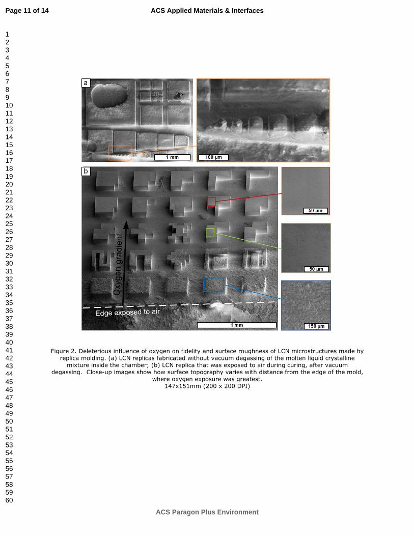
Figure 2. Deleterious influence of oxygen on fidelity and surface roughness of LCN microstructures made by replica molding. (a) LCN replicas fabricated without vacuum degassing of the molten liquid crystalline
mixture inside the chamber; (b) LCN replica that was exposed to air during curing, after vacuum degassing. Close-up images show how surface topography varies with distance from the edge of the mold,
where oxygen exposure was greatest. 147x151mm (200 x 200 DPI)
Page 11 of 14
ACS Paragon Plus Environment
ACS Applied Materials & Interfaces
123456789101112131415161718192021222324252627282930313233343536373839404142434445464748495051525354555657585960
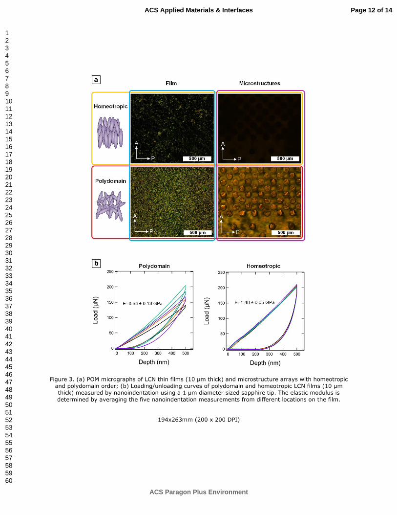
Figure 3. (a) POM micrographs of LCN thin films (10 µm thick) and microstructure arrays with homeotropic and polydomain order; (b) Loading/unloading curves of polydomain and homeotropic LCN films (10 µm thick) measured by nanoindentation using a 1 µm diameter sized sapphire tip. The elastic modulus is
determined by averaging the five nanoindentation measurements from different locations on the film.
194x263mm (200 x 200 DPI)
Page 12 of 14
ACS Paragon Plus Environment
ACS Applied Materials & Interfaces
123456789101112131415161718192021222324252627282930313233343536373839404142434445464748495051525354555657585960
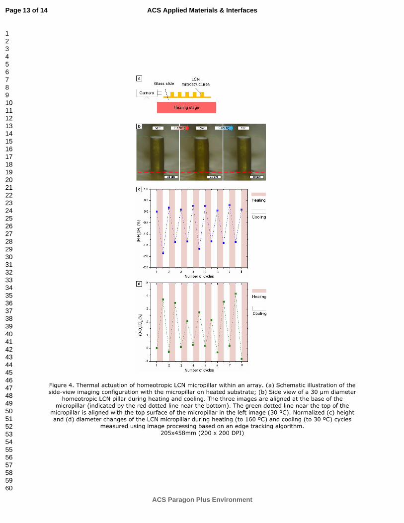
Figure 4. Thermal actuation of homeotropic LCN micropillar within an array. (a) Schematic illustration of the side-view imaging configuration with the micropillar on heated substrate; (b) Side view of a 30 µm diameter
homeotropic LCN pillar during heating and cooling. The three images are aligned at the base of the
micropillar (indicated by the red dotted line near the bottom). The green dotted line near the top of the micropillar is aligned with the top surface of the micropillar in the left image (30 ºC). Normalized (c) height and (d) diameter changes of the LCN micropillar during heating (to 160 ºC) and cooling (to 30 ºC) cycles
measured using image processing based on an edge tracking algorithm. 205x458mm (200 x 200 DPI)
Page 13 of 14
ACS Paragon Plus Environment
ACS Applied Materials & Interfaces
123456789101112131415161718192021222324252627282930313233343536373839404142434445464748495051525354555657585960
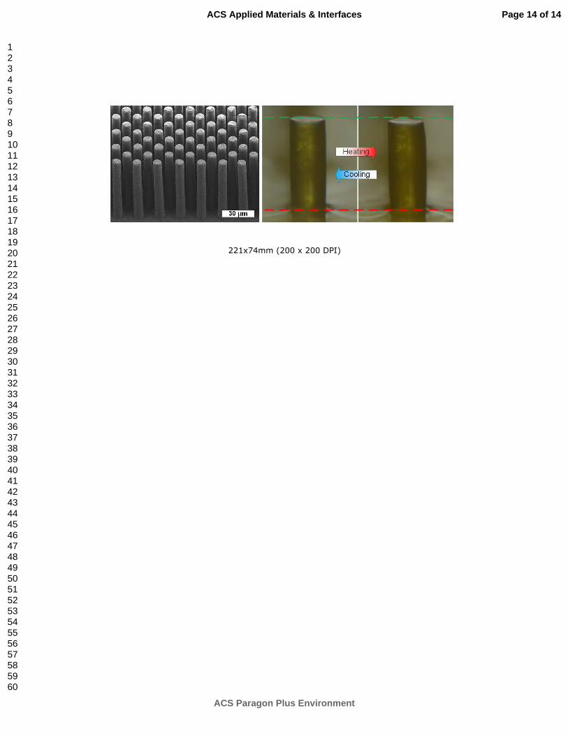
221x74mm (200 x 200 DPI)
Page 14 of 14
ACS Paragon Plus Environment
ACS Applied Materials & Interfaces
123456789101112131415161718192021222324252627282930313233343536373839404142434445464748495051525354555657585960