
LIQUEFIED PETROLEUM GAS INSTALLATION
97
GENERAL SPECIFICATION FOR LIQUEFIED PETROLEUM GAS INSTALLATION IN GOVERNMENT BUILDINGS OF THE HONG KONG SPECIAL ADMINISTRATIVE REGION 2012 EDITION ARCHITECTURAL SERVICES DEPARTMENT THE GOVERNMENT OF THE HONG KONG SPECIAL ADMINISTRATIVE REGION
-
Upload
bluesky11 -
Category
Technology
-
view
127 -
download
3
Transcript of LIQUEFIED PETROLEUM GAS INSTALLATION
GENERAL SPECIFICATION
FOR
LIQUEFIED PETROLEUM GAS INSTALLATION
IN
GOVERNMENT BUILDINGS
OF
THE HONG KONG SPECIAL ADMINISTRATIVE REGION
2012 EDITION
ARCHITECTURAL SERVICES DEPARTMENT
THE GOVERNMENT OF THE HONG KONG SPECIAL ADMINISTRATIVE REGION

PREFACE
This General Specification aims to lay down the technical requirements of
materials and equipment, the standards of workmanship, the requirements on testing and
commissioning as well as requirements on document submissions for Liquefied Petroleum
Gas Installation in Government Buildings of the Hong Kong Special Administrative
Region (HKSAR).
The 2012 edition of this General Specification was developed based on its 2007
edition by the Specialist Support Group that was established under the Building Services
Branch Technical Information and Research & Development Committee of the
Architectural Services Department (ArchSD). This new edition incorporates updated
international standards as well as technological developments which find applications in
Hong Kong. To be in line with the department’s endeavour to reduce the
environmental burden on our neighbours and to help preserving common resources while
improving the quality of our service, this new edition has continued putting emphasis on
green initiatives and initiatives for enhancement of client satisfaction on completed
projects.
With the benefit of information technology, electronic version of this new edition
is to be viewed on and free for download from the Architectural Services Department
(ArchSD) Internet homepage. As part of the Government’s efforts to limit paper
consumption, hard copies of this General Specification will not be put up for sale.
The draft of this edition has been circulated to stakeholders within and external to
the Government before finalization. Nevertheless, the Architectural Services Department
welcomes comments on its contents at anytime since the updating of this General
Specification is a continuous process for the inclusion of any developments that can help
meeting the needs of our community.
DISCLAIMER
This General Specification is solely compiled for a Liquefied Petroleum Gas
Installation carried out for or on behalf of the ArchSD in Government buildings of the
HKSAR.
There are no representations, either expressed or implied, as to the suitability of
this General Specification for purposes other than that stated above. Users who choose to
adopt this General Specification for their Installations are responsible for making their own
assessments and judgement of all information contained here. The ArchSD does not
accept any liability and responsibility for any special, indirect or consequential loss or
damage whatsoever arising out of or in connection with the use of this General
Specification or reliance placed on it.
The materials contained in this document may not be pertinent or fully cover the
extent of the installation in non-government buildings and there is no intimated or implied
endorsement of the sales, supply and installation of the materials and equipment specified
in this General Specification within the territory of the HKSAR.
Table of Contents
Page 1 of 6
LPG_GS
2012 Edition
TABLE OF CONTENTS
PART A – SCOPE AND GENERAL REQUIREMENTS
SECTION A1 SCOPE OF SPECIFICATION
A1.1 Installation to comply with this General Specification
A1.2 Scope of the Installations
A1.3 Terms and Definitions
A1.4 Singular and Plural
A1.5 Design Responsibility
SECTION A2 STATUTORY OBLIGATIONS AND OTHER REGULATIONS
A2.1 Statutory Obligations and Other Requirements
A2.2 Case of Conflict
SECTION A3 EXECUTION OF INSTALLATIONS
A3.1 The International System of Units (SI)
A3.2 Programme of Installations
A3.3 Builder’s Work
A3.4 Coordination of Installations
A3.5 Cooperation with Other Contractors
A3.6 Site Supervision
A3.7 Sample Board
A3.8 Advice of Order Placed
A3.9 Record of Materials Delivery
A3.10 Protection of Materials and Equipment
A3.11 Label Schedule and Chinese Translation
SECTION A4 DRAWINGS AND MANUALS
A4.1 Drawings in Electronic Format
A4.2 Installation Drawings
A4.3 As-built Drawings
A4.4 Operation and Maintenance (O&M) Manual and User Manual
A4.5 Intellectual Property Rights
A4.6 Checking Before Submission
SECTION A5 GENERAL REQUIREMENTS OF THE INSTALLATIONS
A5.1 Tradesmen
A5.2 Training of Employer’s Staff
A5.3 Spares and Tools
A5.4 Safety Facilities
A5.5 Quality Assurance Standards
A5.6 General Design Requirements
A5.7 General Requirements on Operation and Maintenance
Provisions
Table of Contents
Page 2 of 6
LPG_GS
2012 Edition
PART B – GENERAL TECHNICAL REQUIREMENTS
SECTION B1 BULK LPG STORAGE VESSELS
B1.1 General
B1.2 Storage Vessels
B1.3 Pressure Relief Valves
B1.4 Vent Pipes
B1.5 Shut Off Valves and Emergency Valves
B1.6 Filling Connections
B1.7 Drain Connections
B1.8 Gauges
B1.9 Maximum Permitted Filling Volume
B1.10 Location and Safety Distance
B1.11 Arrangement and Separation
B1.12 Finishes and Coating
B1.13 Cathodic Protection
SECTION B2 LPG CYLINDERS
B2.1 General
B2.2 Liquid-Draw System
B2.3 Vapour-Draw System
B2.4 Multi-Cylinders System
B2.5 Simple Domestic Installation
B2.6 Storage of LPG Cylinders
SECTION B3 VAPORISERS
B3.1 Types
B3.2 Capacity
B3.3 Construction
B3.4 Functional Components and Safety Devices
B3.5 Location of Vaporisers
B3.6 Drain and Vent
SECTION B4 PIPING AND FITTINGS
B4.1 Material
B4.2 Steel Pipes
B4.3 Flexible Rubber Hose and Tubing
B4.4 Pipe Joints
B4.5 Pipe Fittings
B4.6 Allowable Pressure Drops
B4.7 Piping Installation
SECTION B5 VALVES AND ACCESSORIES
B5.1 General
B5.2 Excess Flow Valves
B5.3 Non-Return Valves
B5.4 Isolating Valves
Table of Contents
Page 3 of 6
LPG_GS
2012 Edition
B5.5 Quick-Acting Shut-Off Valves
B5.6 Emergency Shut-Off Valves
B5.7 Pressure Relief Valves
B5.8 Hydrostatic Relief Valves
B5.9 Pressure Gauges
B5.10 Meters
SECTION B6 PRESSURE REGULATION
B6.1 Pressure ranges
B6.2 Construction of Pressure Regulators/Governors
B6.3 Primary Pressure Regulator
B6.4 Secondary Pressure Regulator
B6.5 Service Governor
B6.6 Regulators with Over Pressure and/or Under Pressure Shut Off
Devices
B6.7 Regulators/Governors with Full Capacity of Internal Relief
SECTION B7 HAZARD PRECAUTION AND FIRE PREVENTION
B7.1 Electrical & Electrostatic Hazard Precautions
B7.2 Fire Prevention and Control
SECTION B8 MISCELLANEOUS
B8.1 Gas Detection
B8.2 LPG Transfer Procedures
B8.3 Instruction, Labels, Signs and Notices
B8.4 Painting
SECTION B9 CIVIL WORK
B9.1 LPG Compound
B9.2 Enclosure for LPG Cylinder/Plant
B9.3 Ventilation and Explosion Relief Apertures
B9.4 Trenches
B9.5 Walls, Ceiling or Floors
B9.6 Radiation Walls
B9.7 Warning Signs and Labels
Table of Contents
Page 4 of 6
LPG_GS
2012 Edition
PART C – TECHNICAL REQUIREMENTS FOR APPLIANCES
SECTION C1 LPG GAS APPLIANCES
C1.1 Scope of Gas Appliances
C1.2 General Requirements
C1.3 Burners and Associated Parts
C1.4 Outer Casing
C1.5 Control and Regulating Devices
C1.6 Forced Draught Combustion
C1.7 Safety Devices
C1.8 Flame Failure Devices and Associated Safety Shut-Off Valves
C1.9 Associated Gas Installation
C1.10 Flues
C1.11 Testing of Gas Appliance
C1.12 Domestic Instantaneous Type Water Heater
C1.13 Domestic Type Gas Cooker
Table of Contents
Page 5 of 6
LPG_GS
2012 Edition
PART D – INSPECTION, TESTING AND COMMISSIONING
SECTION D1 INSPECTON, TESTING AND COMMISSIONING
D1.1 General
D1.2 Bulk LPG Storage Vessels
D1.3 Vaporisers
D1.4 Pipework Testing
D1.5 Regulators
D1.6 Emergency Valves
D1.7 Pressure Relief Valves
D1.8 Vessel Content Gauge and Fixed Maximum Liquid Level
Devices
D1.9 Gauges
D1.10 Earthing
D1.11 Cathodic Protection System
D1.12 Purging/Gas Filling of Vessels and Systems
D1.13 The Gas Authority Inspections and Witness of Tests
D1.14 Testing and Commissioning Report
Table of Contents
Page 6 of 6
LPG_GS
2012 Edition
PART E – INSPECTION, ATTENDANCE, OPERATION AND
MAINTENANCE DURING MAINTENANCE PERIOD
SECTION E1 MAINTENANCE
E1.1 General Maintenance Requirements
E1.2 Emergency Inspection, Tests and Repairs
E1.3 Routine Maintenance - General
E1.4 Quarterly Inspection, Testing and Servicing
E1.5 Annual Inspection, Testing and Servicing
E1.6 Handover of Liquefied Petroleum Gas Installation
ANNEX I LIST OF TECHNICAL STANDARDS AND QUALITY STANDARDS
QUOTED IN THIS GENERAL SPECIFICATION
Section A1
Page 1 of 4
LPG_GS
2012 Edition
PART A – SCOPE AND GENERAL REQUIREMENTS
SECTION A1
SCOPE OF SPECIFICATION
A1.1 INSTALLATION TO COMPLY WITH THIS GENERAL
SPECIFICATION
The Liquefied Petroleum Gas Installation shall comply with this General
Specification which details the intrinsic properties (including materials and
workmanship) of the installation, in so far as it is not overridden by the
Conditions, Particular Specification, Drawings and/or written instructions of the
Architect.
A1.2 SCOPE OF THE INSTALLATIONS
This General Specification, Particular Specification, Tender Equipment Schedule
and Drawings detail the performance requirements of the Installations. The
Installations to be carried out in accordance with this General Specification shall
include the whole of the installation and supply of all materials necessary to form
a complete installation including any necessary tests, adjustments, commissioning
and maintenance as prescribed and all other incidental sundry components
together with the necessary labour for installing such components, for the proper
operation of the installation.
Unless otherwise specified, the Installations also includes the initial supply of
sufficient quantity of Liquefied Petroleum Gas for testing and commissioning, the
specified quantity of Liquefied Petroleum Gas as indicated in the Particular
Specification and Drawings, and the loan of Liquefied Petroleum Gas bottles.
Subsequent replacement of the Liquefied Petroleum Gas after the initial supply
has been exhausted, will be provided by others. The LPG Contractor shall be
responsible for taking back his on loan bottles after the replacement has been
made.
A1.3 TERMS AND DEFINITIONS
In this General Specification, all words and expressions shall have the meaning as
assigned to them under the Conditions unless otherwise provided herein. The
following words or expressions shall have the meanings assigned to them except
when the context otherwise requires: -
A1.3.1 Terms and Definitions
Architect The Architect or the Maintenance Surveyor or the
Supervising Officer as defined in the Contract as
appropriate
Section A1
Page 2 of 4
LPG_GS
2012 Edition
Building
Contractor
The Contractor employed by the Employer for the
execution of the Works or the Specialist Contractor
separately employed by the Employer to execute the
Specialist Works as appropriate.
Competent
Person
The person who has been recognised by the Gas Authority
under Gas Safety Ordinance (Cap. 51), Laws of the Hong
Kong Special Administrative Region to perform or
supervise or inspect or certify Liquefied Petroleum Gas
Installation, testing and maintenance work.
Conditions The General Conditions of Contract for Building Works
together with the Special Conditions of Contract as defined
in the Contract, Sub-contract for Building Works as
defined in the Nominated Sub-contract as appropriate
LPG Contractor The Nominated sub-contractor or the Specialist
Sub-contractor employed by the Building Contractor or the
contractor directly employed by the Employer as
appropriate for the execution of the Installations in
accordance with the Contract.
Fire Resisting
Period
The period of time during which the material can withstand
fire as defined by the Buildings Department of the Hong
Kong Special Administrative Region.
High Pressure
Stage
That part of the installation between the valve of the bulk
storage vessel/cylinder and the inlet of the pressure
regulator; the pressure range is exceeding 69 kPa.
Installations The work or services for the Liquefied Petroleum Gas
Installation forming parts of the Works to be installed,
constructed, completed, maintained and/or supplied in
accordance with the Contract and includes Temporary
Works
Low Pressure
Stage
That part of the installation between the second stage
regulator (or the outlet of the high pressure regulator if no
medium stage is used) and the inlet of the appliance, the
pressure range is up to 6.9 kPa.
Medium Pressure
Stage
That part of the installation between a first stage regulator
and a second stage regulator; the pressure range is from
exceeding 6.9 kPa to 69 kPa.
Notifiable Gas
Installation
LPG installation with either a storage capacity exceeding
130 litre water capacity or a liquid draw-off arrangement
irrespective of the capacity or as defined by the Gas
Authority is classified as notifiable gas installation.
Construction approval, type approval of gas container and
approval of use from Gas Authority are required for the
notifiable gas installation.
Section A1
Page 3 of 4
LPG_GS
2012 Edition
Particular
Specification
The specifications drawn up specifically for the
Installations of a particular project
Tender The Contractor’s tender for the Contract or the Nominated
Sub-contractor’s tender for the Nominated Sub-contract as
appropriate
ANSI American National Standards Institute
API American Petroleum Institute
ASME American Society of Mechanical Engineers
ASTM American Society for Testing and Material
BS British Standards, including British Standard
Specifications and British Standard Codes of Practice,
published by the British Standard Institution
BSB Building Services Branch, Architectural Services
Department of the Hong Kong Special Administrative
Region
BS EN European Standard adopted as British Standard
BS/E&M Building Services / Electrical & Mechanical
BGC Centrica Plc / BG Plc of United Kingdom (previously
known as British Gas Corporation of United Kingdom)
CGA Canadian Gas Association
EE_TCP Testing and Commissioning Procedure for Electrical
Installation in Government Buildings of the Hong Kong
Special Administrative Region issued by the Architectural
Services Department
EMSD Electrical and Mechanical Services Department of the
Hong Kong Special Administrative Region
EPA Environmental Protection Agency
FSD Fire Services Department of the Hong Kong Special
Administrative Region
GasSO Gas Standards Office of the Electrical and Mechanical
Services Department of the Hong Kong Special
Administrative Region
HKSAR Hong Kong Special Administrative Region
IP Institute of Petroleum
Section A1
Page 4 of 4
LPG_GS
2012 Edition
ISO International Organization for Standardisation Publications
JIS Japanese Industrial Standards
LPG Liquefied Petroleum Gas as defined under the Gas Safety
Ordinance (Cap. 51)
LPG_TCP Testing and Commissioning Procedure for Liquefied
Petroleum Gas Installation in Government Buildings of the
Hong Kong Special Administrative Region issued by the
Architectural Services Department
NFPA National Fire Protection Association of United States
UKLPG Liquefied Petroleum Gas Association of United Kingdom
(previously known as Liquefied Petroleum Gas Industry
Technical Association)
WSD Water Supplies Department of the Hong Kong Special
Administrative Region
A1.4 SINGULAR AND PLURAL
Words importing the singular only also include the plural and vice versa where
the context requires.
A1.5 DESIGN RESPONSIBILITY
Where design is specified for any part of the Installations, the LPG Contractor
shall design the Liquefied Petroleum Gas Installation to comply with the statutory
requirements as well as the requirements in the Specification. Where design is
not specified, the LPG Contractor shall still develop the design shown in the
Drawings or in the Particular Specification, complete the detailed design and
installation details of the whole Liquefied Petroleum Gas Installation and select
the most appropriate equipment design to comply with the statutory requirements
and all other requirements of the Specification. All design drawings, calculation
and installation details shall be submitted to the Architect for approval.
All design shall be checked and endorsed by a qualified and experienced staff of
the LPG Contractor approved by the Architect before submission.
Section A2
Page 1 of 3
LPG_GS
2012 Edition
SECTION A2
STATUTORY OBLIGATIONS AND OTHER REGULATIONS
A2.1 STATUTORY OBLIGATIONS AND OTHER REQUIREMENTS
The LPG installation shall comply with the statutory obligations stipulated in the
following Laws of the HKSAR and other documents currently in force:
A2.1.1 All Enactments and Regulations, in particular, the LPG Contractor’s
attention is drawn to the followings :
(a) Gas Safety Ordinance, (Cap. 51), Laws of the HKSAR and all
the Gas Safety Regulations;
(b) Buildings Regulations, (Cap. 123), Laws of the HKSAR;
(c) Dangerous Good Ordinance, (Cap. 295), Laws of the HKSAR;
(d) Electricity Ordinance, (Cap. 406), Laws of the HKSAR and the
associated Electricity (Wiring) Regulations and Code of
Practice;
(e) Water Works Regulations, (Cap. 102), Laws of the HKSAR;
(f) Fire Service (Installation and Equipment) Regulations, Fire
Services Ordinance, (Cap. 95), Laws of the HKSAR;
(g) Water Pollution Control Ordinance, (Cap. 358), Air Pollution
Control Ordinance, (Cap. 311), Noise Control Ordinance,
(Cap. 400), Laws of the HKSAR and all the statutory
regulations related to the environmental protection;
(h) Waste Disposal Ordinance, (Cap. 354) and other subsidiary
legislation made under the Ordinance; and
(i) Environmental Impact Assessment Ordinance, (Cap. 499) and
other subsidiary legislation made under the Ordinance.
A.2.1.2 Other Requirements
(a) Code of Practice for the Electricity (Wiring) Regulations
published by the EMSD;
(b) Codes of Practice for Minimum Fire Service Installations and
Equipment and Inspection, testing and Maintenance of
Installations and Equipment published by the FSD;
Section A2
Page 2 of 3
LPG_GS
2012 Edition
(c) Requirements and Circular Letters of the FSD;
(d) Code of Practice for Hong Kong LPG Industry published by the
GasSO;
(e) Gas Utilisation Code of Practice GU03, GU04, GU05, GU06,
GU09 and GU16 published by the GasSO;
(f) Other Codes of Practice published by the GasSO ;
(g) Codes of Practice published by the UKLPG, or acceptable
equivalent;
(h) General Specification for Electrical Installation in Government
Buildings of the Hong Kong Special Administrative Region
issued by the ArchSD;
(i) General Specification for Air Conditioning, Refrigeration,
Ventilation and Central Monitoring and Control System
Installation in Government Building of the Hong Kong Special
Administrative Region issued by the ArchSD;
(j) General Specification for Fire Service Installation in
Government Buildings of the Hong Kong Special
Administrative Region issued by the ArchSD;
(k) Codes and Standards published by the National Fire Protection
Association (NFPA), American National Standards Institute
(ANSI), American Society of Mechanical Engineers (ASME),
American Society of Material Association (ASTM), United
States; and
(l) Equivalent standard that is acceptable to the Architect and the
GasSO when a code or standard is specified in the Specification.
A2.1.3 Safety Requirements
(a) Construction Sites (Safety) Regulations;
(b) Factories and Industrial Undertakings Ordinance, (Cap. 59),
Laws of the HKSAR and other subsidiary legislation made
under the Ordinance;
(c) Factories and Industrial Undertakings (Electrical) Regulations;
(d) Factories and Industrial Undertakings (Safety Officers and
Safety Supervisors) Regulations;
(e) Factories and Industrial Undertakings (Confined Spaces)
Regulations;
Section A2
Page 3 of 3
LPG_GS
2012 Edition
(f) Public Health and Municipal Service Ordinance, (Cap. 132),
and other subsidiary legislation made under the Ordinance;
(g) Construction Site Safety Manual issued by the Environment,
Transport and Works Bureau, the Government of the HKSAR;
and
(h) Occupation Safety and Health Ordinance, (Cap. 509), Laws of
the HKSAR.
A2.1.4 Technical Standards
BS, BS EN, ISO Standards, IEC Standards and Codes of Practice, etc.,
and other technical standards, quality standards, rules, design manuals,
guidelines, technical requirements and specifications in this General
Specification shall be deemed to include all amendments, revisions and
standards superseding the standards listed herein, which are published
before the date of first tender invitation for the Contract or the
Nominated Sub-contract (as appropriate), unless otherwise specified or
unless the latest amendments are not approved or allowed by relevant
authorities under the statutory regulations. Equivalent International
Standards may be used if approved by the Architect.
Materials, equipment and products that comply with equivalent technical
standards and demonstrated to be equivalent in overall technical
substitute on the type of construction, functions, performance, general
appearance and standard of quality of manufacture to the standards and
requirements listed herein may be submitted for approval by the
Architect.
A summary of technical standards quoted in this General Specification to
which the Installations shall comply is listed in Annex I.
A2.2 CASE OF CONFLICT
The documents forming the Contract are to be taken as mutually explanatory of
one another but in case of ambiguities or discrepancies the same shall be dealt
with in accordance with the Conditions.
Section A3
Page 1 of 6
LPG_GS
2012 Edition
SECTION A3
EXECUTION OF INSTALLATIONS
A3.1 THE INTERNATIONAL SYSTEM OF UNITS (SI)
The International System of Units (System International d’Unites) of weights and
measures shall be used for all materials, equipment and measurements.
A3.2 PROGRAMME OF INSTALLATIONS
The LPG Contractor shall submit to the Architect a detailed programme of the
Installations within 4 weeks from the acceptance of his Tender showing the
intended method, stages and order of Installations execution in coordination with
the building construction programme, together with the duration he estimated for
each and every stage of the Installations. The programme shall include at least the
following:
(a) Dates for the placement of orders for equipment and materials;
(b) Expected completion dates for builder’s work requirements, i.e. when
work site needs to be ready;
(c) Delivery dates of equipment and materials to Site;
(d) Dates of commencement and completion of every stage of the
Installations in line with the building construction programme, i.e. each
floor level and/or zone area;
(e) Dates of documents/drawings submissions to relevant Government
departments to obtain the necessary approvals;
(f) Dates of requirement of temporary facilities necessary for testing &
commissioning, e.g. electricity supply, water and town gas;
(g) Dates of completion, testing and commissioning; and
(h) Short term programmes showing the detailed Installations schedules of
coming weeks and months shall also be provided to the Architect.
Programmes shall be regularly updated to reflect the actual progress and
to meet the obligations under the Contract.
In addition, detailed submission schedules for installation drawings, equipment
and testing and commissioning shall be submitted to the Architect for approval.
The formats and information to be included in the schedules shall be as required
by the Architect.
Section A3
Page 2 of 6
LPG_GS
2012 Edition
A3.3 BUILDER’S WORK
All builder’s work including pipework openings or holes through building
structure or partition walls; trenches, ducts and cutting; and all plinths, concrete
bases, supports, ducts etc. required for the installation will be carried out as part
of the building works by the Building Contractor at the expense of the Employer
provided that the LPG Contractor has submitted full details of such requirements
within a reasonable time to the Architect for approval, so that due consideration
may be given before the Building Contractor commences the building works in
accordance with the building programme in the areas concerned.
After obtaining the said approval of the Architect, the LPG Contractor is required
to mark out at the relevant locations of the Site the exact positions and sizes of all
such works and to provide detailed information of such works to the Building
Contractor to facilitate him to carry out the builder’s works as the Works proceed.
Builder’s work shall include civil work in Section B9 of this General
Specification unless otherwise specified.
All ‘cutting-away’ and ‘making-good’ as required to facilitate the LPG
Contractor’s works will be carried out by the Building Contractor, except for
minor provisions required for the fixing of screws, raw plugs, redhead bolts, etc.
which shall be carried out by the LPG Contractor. The LPG Contractor shall
mark out on Site and/or supply drawings of all ‘cutting-away’ to the Building
Contractor within a reasonable time.
All expenses properly incurred and losses suffered by the Employer as a result of
the LPG Contractor’s failure to comply with the above requirements are
recoverable by the Employer from the LPG Contractor as a debt under the
Contract or via the Building Contractor as if it is a debt liable to the Building
Contractor under the Sub-contract as appropriate.
The LPG Contractor shall ensure that such works are essential for the execution
of the Installations. In the event that any of such works is proved to be
non-essential, unnecessary and/or abortive, the LPG Contractor shall bear the full
cost of such works including but not limited to any unnecessary or incorrect
cutting-away and making-good and all cost incurred in this connection are
recoverable by the Employer from the LPG Contractor as a debt under the
Contract or via the Building Contractor as if it is a debt liable to the Building
Contractor under the Sub-contract as appropriate.
Upon completion of the builder’s works by the Building Contractor, the LPG
Contractor shall forthwith check and examine that all builder’s works so executed
have been completed in accordance with his requirements. If at any time it
becomes apparent to the LPG Contractor that any builder’s works completed by
the Building Contractor does not comply with his requirements in any respect
whatsoever, the LPG Contractor shall forthwith give notice in writing to the
Architect and specify in details the extents and effects of such non-compliance in
that notice. The LPG Contractor is deemed to have satisfied with the builder’s
works after a period of 14 days from the date of completion of the builder’s
works if the above notice is not served to the Architect within such period. All
additional expenditure properly incurred and all loss suffered in this connection
by the Employer in having such works re-executed and rectified shall be
Section A3
Page 3 of 6
LPG_GS
2012 Edition
recoverable by the Employer from the LPG Contractor as a debt under the
Contract or via the Building Contractor as if it is a debt liable to the Building
Contractor under the Sub-contract as appropriate.
A3.4 COORDINATION OF INSTALLATIONS
The LPG Contractor shall coordinate the Installations with those works of the
Building Contractor and any other contractors and sub-contractors of the
Building Contractor.
The LPG Contractor shall note that the Drawings supplied to him only indicate
the approximate location of his Installations. He shall make any modification
reasonably required of his programme, work sequence and physical deployment
of his work to suit the outcome of work coordination or as necessary and ensure
that all cleaning, adjustment, test and control points are readily accessible while
keeping the number of loops, cross-overs and the like to a minimum.
The programme of Installations shall also be coordinated to the satisfaction of the
Architect and adhere to the approved overall construction programme.
Any significant problems encountered during the coordination work, which are
beyond the LPG Contractor’s control shall promptly be reported to the Architect
for advice and/or decision.
A3.5 COOPERATION WITH OTHER CONTRACTORS
The LPG Contractor shall cooperate at all times with the Building Contractor and
all other contractors and sub-contractors of the Building Contractor in order to
achieve efficient workflow on the Site.
Any significant problems beyond the LPG Contractor’s control shall promptly be
reported to the Architect for advice and/or decision. No extra claim for delay
either financially or extension of the Contract Period will be allowed if the LPG
Contractor fails to properly and adequately co-ordinate and programme the work
at all times.
A3.6 SITE SUPERVISION
The LPG Contractor shall keep on the Site a competent and technically qualified
site supervisor to control, supervise, co-ordinate and manage all his works on Site.
The site supervisor shall be vested with suitable powers to receive instructions
from the Architect.
The site supervisor shall be technically competent and have adequate site
experience for the Installations. The LPG Contractor shall also refer to the
Particular Specification for other specific requirements, if any, on site
supervision.
Section A3
Page 4 of 6
LPG_GS
2012 Edition
Approval by the Architect shall be obtained prior to the posting of the site
supervisor on Site. The LPG Contractor shall immediately replace any site
supervisor whose experience, skill or competency is, in the opinion of the
Architect, found to be inadequate for the particular work.
The LPG installation including the maintenance works shall be carried out by a
competent person or by a person under the direct (on site) supervision of a
Registered Gas Installer in accordance with the Gas Safety Ordinance, (Cap. 51),
Laws of the Hong Kong Special Administrative Region. For the part of work
which is falling into the meaning of ‘gas installation work’ as defined in the Gas
Safety (Registration of Gas Installers and Gas Contractors) Regulation 2, a
Registered Gas Contractor who is registered with the Gas Authority under the
registration scheme shall be employed to carry out the work.
All Installations shall be carried out in such a manner so as to comply with the
Gas Safety Ordinance (Cap. 51), the Construction Site Safety Regulations and the
Factories & Industrial Undertakings under Laws of the Hong Kong Special
Administrative Region.
The LPG Contractor shall implement a work permit system where work is
required to be carried out on the installation in which LPG has been loaded . The
LPG Contractor shall be responsible to take every fire precautionary measures.
He shall also be responsible for putting up warning signs at prominent positions
on site to warn other contractors of the existence of the inflammable gases.
A3.7 SAMPLE BOARD
Within 6 weeks of the award of the Contract and prior to the commencement of
installation work, the LPG Contractor shall submit to the Architect for approval
in good time a sample board of essential components proposed to be used in the
Contract. However, the LPG Contractor may request the Architect in writing
for a longer period for the submission, if 6 weeks are practically insufficient.
Items displayed shall deem to be adequate for the whole Installations unless
otherwise clearly indicated. Each sample, with clear numbering and labelling,
shall be firmly fixed onto a rigid wooden or metal board. A list shall also be
affixed on the sample board to show the item description, make and brand,
country of origin and locations of installation (if not generally used). Samples
rejected by the Architect shall be replaced as soon as possible. Upon approval
of all items, the Architect will endorse the list on the sample board and the LPG
Contractor shall deliver the board to the site office for reference.
The following items shall be included in the sample board as a minimum.
Additional items may be required by the Architect and/or specified in the
Particular Specification.
(a) pipework, fitting and support; and
(b) flexible rubber hose and tubing.
Section A3
Page 5 of 6
LPG_GS
2012 Edition
A3.8 ADVICE OF ORDER PLACED
The LPG Contractor shall submit copies of all orders placed for major items of
equipment and materials to the Architect for record.
A3.9 RECORD OF MATERIALS DELIVERY
For the purpose of assessing interim payment, all materials delivered to Site shall
be accurately listed and recorded in the site record books maintained by the
Architect’s Representatives on Site.
Materials and equipment delivered to Site are the Employer’s property. Such
materials and equipment shall not be removed from Site without the prior
approval of the Architect in writing.
Where the Building Contractor is in overall control of the Site, the Building
Contractor may also be required to record details of all incoming/outgoing
materials. In this case, the LPG Contractor shall comply with the Building
Contractor’s arrangements.
A3.10 PROTECTION OF MATERIALS AND EQUIPMENT
Unless the responsibility is clearly defined in the Contract that the protection on
Site for delivered equipment, materials and installation is solely by other
contractors, the LPG Contractor shall be responsible for the safe custody of all
materials and equipment as stored or installed by him. In addition, the LPG
Contractor shall protect all work against theft, fire, damage or inclement weather
and carefully store all materials and equipment received on Site but not yet
installed in a safe and secure place unless otherwise specified.
All cases of theft and fire must immediately be reported to the police, the
Building Contractor, the Architect and the Architect’s Representatives on Site
with full details.
Where necessary the LPG Contractor shall provide lockable steel container or
other equally secure enclosures placed within a securely fenced-in compound
provided by the Building Contractor on Site for the storage of materials and
equipment.
The LPG Contractor shall co-ordinate and arrange with the Building Contractor
who shall provide clean, reasonably finished and lockable secure accommodation
for the storage of sensitive and/or expensive items before installation. If the
Building Contractor fails to concede to the request, the LPG Contractor shall
report the shortcomings of the accommodation to the Architect.
If there is no Building Contractor, all the storage facilities and spaces shall be
provided by the LPG Contractor.

Section A3
Page 6 of 6
LPG_GS
2012 Edition
A3.11 LABEL SCHEDULE AND CHINESE TRANSLATION
TheLPG Contractor shall submit a schedule for all labels, notices, identifications
and instructions for the Architect’s approval prior to order and installation. The
information of the schedule shall include the description of the items, height and
font type of the text, dimensions of the labels and material used. The Chinese
translation shall be referred to the “Glossaries of Terms Commonly Used in
Government Departments” issued by the Civil Service Bureau of the Government
of the HKSAR.
Section A4
Page 1 of 12
LPG_GS
2012 Edition
SECTION A4
DRAWINGS AND MANUALS
A4.1 DRAWINGS IN ELECTRONIC FORMAT
The LPG Contractor shall provide drawings in electronic format as required in the
following clauses. These drawings shall conform to the latest version of CAD
Standard of Works Projects (CSWP) as posted in the web site of the Works
Branch, Development Bureau and in accordance with the latest version of CAD
Manual for Architectural Services Department Projects. Should any technical
conflict between the CSWP and the CAD Manual arise, the CSWP shall take
precedence.
A4.2 INSTALLATION DRAWINGS
A4.2.1 Drawing Submission Schedule
The LPG Contractor shall submit a detailed installation drawing
submission schedule and programme to the Architect. The LPG
Contractor shall allow reasonable time in the programme for vetting of
the installation drawings by the Architect and for drawing resubmissions
as necessary.
The LPG Contractor shall submit to the Architect a comprehensive
"Submission Schedule" of installation drawings and builder’s work
drawings within 2 weeks after the acceptance of Tender, taking into
account of the overall programme of the Installations including any
Specialist Works and works by the utility undertakings. No equipment
shall be delivered to the Site and no works shall be executed until the
installation drawings have been approved by the Architect. The LPG
Contractor shall ensure that the installation drawings and builder’s work
drawings are progressively submitted in accordance with the approved
"Submission Schedule".
The LPG Contractor shall provide at least 6 hard copies and one
electronic copy, unless otherwise specified in the Contract, of the
approved installation drawings to the Architect for distribution.
A4.2.2 Size of Installation Drawings
Drawings submitted by the LPG Contractor shall only be of standard
sizes from A0 to A4 or B1 size as stipulated in ISO 5457/Amd1:2010.
A4.2.3 Contents of Installation Drawings
The LPG Contractor shall ensure all installation drawings are accurate
representation of the Installations, before submitting them to the
Section A4
Page 2 of 12
LPG_GS
2012 Edition
Architect. All installation drawings shall be fully dimensioned and
suitably scaled showing construction, sizes, weights, arrangements,
operating clearances and performance characteristics.
Installation drawings including manufacturer’s shop drawings shall be
prepared and submitted to the Architect for perusal by the LPG
Contractor in sequence with the Building Contractor’s construction
programme. They shall contain plan layouts, sectional drawings
(elevations and plans), vertical schematic line diagrams, schematic
wiring diagrams, installation details, etc. and shall show the following
particulars:
(a) Service routings and levels relative to the structure and other
services;
(b) Plant and equipment locations with dimensions and weights; and
(c) Service joints, supports and fixing details together with their
locations.
Maintenance accesses, facilities and all necessary details relating to the
proper operation and maintenance of the systems.
A4.2.4 Builder’s Work Drawings
Unless otherwise approved by the Architect, the LPG Contractor shall
submit to the Architect in accordance with the approved "Submission
Schedule", 6 copies of drawings showing details of all builder’s work
required e.g. the weight and the load on each support of equipment.
Such drawings shall clearly indicate the details and positions of all holes,
trenches, ducts and cutting required and construction details for plinths
and equipment bases.
A4.2.5 Manufacturer’s Shop Drawings
The manufacturer’s shop drawings are drawings for equipment or plant
to be manufactured by a specialist manufacturing supplier in their own
workshops and places away from the Site.
The drawings shall show detailed construction, principal dimensions,
weights and clearances for maintenance, etc. Immediately after placing
of any order or at any event within 4 weeks unless otherwise approved in
writing by the Architect, the LPG Contractor shall forward to the
Architect for comment, 4 copies of manufacturer’s shop drawings,
indicating detailed construction, principal dimensions and weights,
clearances for withdrawals and/or cleaning, etc. No work shall proceed
on or off the Site unless drawings requiring approval are so approved in
writing by the Architect.
Section A4
Page 3 of 12
LPG_GS
2012 Edition
A4.2.6 Drawings for Submission to Other Authority (FSD / GasSO / EMSD /
WSD etc)
The LPG Contractor shall ensure that construction approval where
necessary from the Gas Authority has been obtained prior to
commencing construction work of the LPG installation on Site. The
LPG Contractor shall submit installation drawings and other necessary
information to the Gas Authority for construction approval.
A4.3 AS-BUILT DRAWINGS
A4.3.1 Submission of As–built Drawings
The LPG Contractor shall submit 3 sets of the first draft prints of as-built
drawings within 28 days of the issuance of the certification of
completion. The Architect after checking the above draft prints shall
return one set of the marked up copies of these as-built drawings to the
LPG Contractor within 42 days from the date of submission of the LPG
Contractor’s draft prints with comments. The LPG Contractor shall
within a further 28 days from the date of receiving the Architect’s
comments on the draft as-built drawings re-submit to the Architect for
his approval another 3 sets of the second draft prints of as-built drawings
with the Architect’s comments incorporated. This process of submission
and approval shall continue until the final approval of the Architect on
these as-built drawing is obtained.
The final approved as-built drawings shall be in 3 sets of hard copy and 3
sets of electronic copies. These shall be submitted within 21 days from
the date of final approval. Each electronic copy shall be in the form of
CD-ROM, labelled, with cross reference to a printed list of files
explaining the contents and purpose of each file and supplied in sturdy
plastic containers.
The detailed requirements and the media of as-built drawings set out in
the Preliminaries of the Bills of Quantities or the Specification
Preliminaries shall be followed as appropriate.
A4.3.2 Size of As-built Drawings
As-built drawings shall only be of standard sizes of A0, A1 or B1 size as
stipulated in ISO 5457/Amd1:2010. Smaller size (A2 to A4) is
accepted for installation drawings.
A4.3.3 Content of As-built Drawings
The LPG Contractor shall ensure all as-built drawings are accurate
representation of the Installations, before submitting them to the
Architect. The as-built drawings required to be provided by the LPG
Section A4
Page 4 of 12
LPG_GS
2012 Edition
Contractor for various types of BS/E&M installations shall include, but
not limited to the followings:-
(a) Building services layout plans such as ducting arrangement,
trunking arrangement, piping arrangement, etc.;
(b) System schematic diagrams, control diagrams and wiring
diagrams;
(c) Concealed work layout plan such as concealed conduit routing,
etc.; and
(d) Installation details and assembly drawings such as bulk LPG
vessel, LPG vaporizer, etc.
A4.3.4 Framed Drawings
On completion and before the acceptance of the LPG installation, the
LPG Contractor shall provide a framed drawing with glass cover and fix
it on the wall of all the LPG stores/vaporiser rooms. The drawing shall
indicate schematically all the pipe routes, positions of main controls and
all sectional cocks or valves, meters, pressure testing points, etc and site
layout plan to the approval of the Architect. A log book shall be provided
and kept on site recording all operational checks and maintenance.
A4.4 OPERATION AND MAINTENANCE (O&M) MANUAL AND USER
MANUAL
A4.4.1 General
The LPG Contractor shall provide two types of manuals to the Architect
with all changes made to the installation during the course of the
Contract suitably incorporated.
The O&M Manual is for use by the maintenance agent of the completed
installation. It shall contain detailed technical information covering
both operation and maintenance aspects of the installation.
The User Manual seeks to enable the user of the completed installation
an overview of the essential information of the installation. The
contents of the manual should be concise and succinct for ease of
comprehension by people with a non-technical background.
A4.4.2 Checking and Approval
The LPG Contractor shall supply 3 sets of the first draft of O&M
Manuals together with a list of recommended spare parts for one year’s
operation and a list of special tools, both complete with prices to the
Architect for comment at least 56 days prior to the testing and
Section A4
Page 5 of 12
LPG_GS
2012 Edition
commissioning of the plant and equipment or within 28 days of the
issuance of the certification of completion.
The LPG Contractor shall submit 3 sets of the first draft of the User
Manual to the Architect for comment at least 56 days before the date of
completion.
The Architect will check the drafts and return them to the LPG
Contractor within 42 days from the date of submission by the LPG
Contractor with comments necessary for final and approved set of
document. The LPG Contractor shall then make all necessary
amendments to the documents and resubmit them to the Architect within
21 days from the date of receipt of comments.
The LPG Contractor shall submit 3 sets of hard copies (one of which
shall be the original) and one set of electronic copy of the final approved
O&M manuals in CD-ROM, labelled, with cross reference to a printed
list of files explaining the contents and purpose of each file and supplied
in sturdy plastic containers, within 21 days from the date of approval by
the Architect.
A4.4.3 Structure and Content of O&M Manual
The detailed requirements, structure and contents of the O&M manual
shall be as specified in the Contract Preliminaries or shall include the
following information under separate sections where appropriate:
(a) Project Information
The following information shall be included:-
Project title, site address, contract no., contract title, LPG
Contractor/sub-contractor name, address, contact persons and
their telephone/fax nos., contract commencement date,
substantial completion date and end date of maintenance period.
(b) System Description
(i) Type(s) of system(s) and equipment installed;
(ii) Design criteria, design data and parameters;
(iii) Locations of the system and major equipment, and
what they serve;
(iv) Description of operation and functions of the system
and equipment; and
(v) General operating conditions, expected performance
and energy and resources consumption where
applicable.
Section A4
Page 6 of 12
LPG_GS
2012 Edition
(c) List of Installed Equipment
Schedule of all items of equipment and plant stating the location,
name, model no., manufacturer’s serial or reference no.,
manufacturer’s design duties and data.
(d) Spare Parts and Special Tools Lists
(i) List of Spare Parts supplied by LPG Contractors:
Item descriptions, supplied quantities, model nos.,
manufacturer’s serial or reference nos. and storage
locations.
(ii) Recommended Spare Parts List and Special Tools List:
Manufacturers’/suppliers’ recommendations for spare
parts and special tools with item description, unit rate,
recommended stock quantities as well as the agents for
the spare parts and special tools.
(e) Manufacturers’ Certificates/Guarantees
(i) Manufacturers’ certificates such as factory test
certificate, laboratory test reports, guarantees and any
others where required for the equipment and plants
etc.;
(ii) Originals of Statutory Inspection Certificate for various
installations, including :-
- Construction approval and approval of use issued
by the GasAuthority;
- Written approval of LPG container(s) issued by the
Gas Authority; and
- Surveyor certificate of the bulk LPG vessels.
(iii) Testing records & commissioning data (other than the
types prescribed above), which are required under the
Contract such as the T&C procedures, etc to verify the
compliance of the BS/E&M system’s/equipment’s
performance with the Contract requirements, are
checked and endorsed separately by the Architect and
do not form part of the O&M manuals.
(f) Safety Precautions for Operation & Maintenance
State, where applicable, hazard warnings and safety precautions
of which the operation and maintenance staff need to be aware:
(i) mandatory requirements relating to safety;
(ii) known hazards against which protection measures shall
be taken; and
Section A4
Page 7 of 12
LPG_GS
2012 Edition
(iii) known features or operational characteristics of the
installed equipment or systems which may cause
hazard and the related safety precautions.
(g) Operation Instructions
Instructions for the safe and efficient operation, under both
normal and emergency conditions, of the installed system which
shall comprise :
(i) an outline of the operating mode;
(ii) control logic and data (sequence, effect, limits of
capability, modes and set points);
(iii) procedures and sequences for start-up and shut-down;
(iv) interlocks between equipment/system;
(v) calling on of stand-by equipment;
(vi) precautions necessary to overcome known hazards;
(vii) means by which any potentially hazardous equipment
can be made safe;
(viii) estimation of energy consumption and energy costs;
(ix) forms for recording plant running hours, energy
consumption and energy costs; and
(x) operating data such as running current, operating
pressure, operating flow rates etc.
(h) Maintenance
(i) Maintenance instructions
Manufacturers’ and LPG Contractor/ subcontractor’s
recommendations and instructions for the maintenance
of the installed equipment. In particular, the detailed
requirements of periodic test and examination of
vaporisers for ascertaining their fitness for use to
vaporize LPG shall be submitted. Clear distinction
should be made between planned tasks (preventive
maintenance) and fault-repair tasks (corrective
maintenance). Instructions shall be given on each of
the following, as appropriate :
- nature of deterioration, and the defects to be
looked for;
Section A4
Page 8 of 12
LPG_GS
2012 Edition
- isolation and return to service of plant and
equipment;
- dismantling and reassembly;
- replacement of components and assemblies;
- dealing with hazards which may arise during
maintenance;
- adjustments, calibration and testing; and
- special tools, test equipment and ancillary services.
(ii) Maintenance schedules
Proposed maintenance schedules for all the preventive
maintenance tasks identified above. The schedules
shall be based on both manufacturers’
recommendations and other authoritative sources (e.g.
statutory or mandatory requirements) and shall
include :
- routine servicing;
- inspections;
- tests and examinations;
- re-painting of pipework;
- replacement of items of specified durability or
service life;
- adjustments;
- calibration; and
- overhaul.
The frequency of each task may be expressed as
specific time intervals, running hours or number of
completed operations as appropriate. Collectively, the
schedules will form a complete maintenance cycle,
repeated throughout the whole working life of the
installation.
(i) Drawing Lists
(i) A complete list of as-built drawings identified with
drawing number/reference;
(ii) A complete list of manufacturers’ shop drawings with
drawing number/reference, where applicable; and
(iii) A brief description of CD-ROM for these drawings.
(j) Technical Literatures
A complete set of manufacturers’ literatures for all the plant and
equipment installed in the system. The contents of these
literatures shall cover the following areas where applicable:
Section A4
Page 9 of 12
LPG_GS
2012 Edition
(i) description of equipment with model numbers
highlighted;
(ii) performance - behavioural characteristics of the
equipment;
(iii) applications - suitability for use;
(iv) factory/laboratory test reports, detailed drawings,
circuit diagrams;
(v) methods of operation and control;
(vi) operation instructions;
(vii) cleaning and maintenance requirements;
(viii) plants, materials and space required for maintenance;
(ix) protective measures and safety precautions for
operation & maintenance; and
(x) part lists.
(k) Contact addresses and telephone numbers of suppliers of major
equipment.
A4.4.4 Structure and Content of User Manual
The detailed requirements, structure and contents of the User Manual
shall include, where applicable, the following information:
(a) Project Information
The following information shall be provided:
Project title, site address, contract no., contract title, contract
commencement date, substantial completion date and end date
of maintenance period.
(b) System Description
(i) Type(s) of system(s) and equipment installed, and their
purposes;
(ii) Location of major plant rooms and riser ducts;
(iii) Brief description of the operation and functions of the
systems and equipment; and
Section A4
Page 10 of 12
LPG_GS
2012 Edition
(iv) Listing of set points which can be adjusted by the user
to suit their operation needs.
(c) Schedule of Major Plant Rooms and Installed Equipment
(i) Schedule of major plant rooms and riser ducts
including their locations;
(ii) Schedule of major equipment and plants including their
locations and serving areas.
(d) Safety Precautions for Operation
Any safety precautions and warnings signals in the daily
operation of the various systems and equipment in the
installation including:
(i) mandatory requirements relating to safety;
(ii) features or operational characteristics of the installed
systems or equipment which may cause hazard and the
related safety precautions;
(iii) protective measures and safety precautions for
operation; and
(iv) list of warning signals and the related meanings that the
user shall be aware of.
(e) Operation Instructions
Instructions for the safe and efficient operation, under both
normal and emergency conditions, of the installed system which
shall comprise :
(i) an outline of the operating mode;
(ii) step by step operation instructions for systems and
equipment that are to be operated by the user, including
at least procedures for start-up and shut-down;
(iii) means by which any potentially hazardous situation
can be made safe; and
(iv) cleaning and basic maintenance procedures;
(f) List of Statutory Periodic Inspections and Tests
A schedule of periodic inspections and tests that owner and/or
user of the installation have to arrange to achieve compliance
with the requirements stipulated in the relevant Laws of the
Section A4
Page 11 of 12
LPG_GS
2012 Edition
Hong Kong. The frequency of such inspections and tests shall
be expressed in specific time intervals.
(g) Drawings
A set of selected as-built drawings which shall be able to
illustrate to the user the general layout of the completed
installation.
(h) Photographs
A set of photographs with suitable captions to illustrate to the
user the appearance and locations of devices which require their
setting and operation.
A4.4.5 Presentation
All manuals shall be written in English, unless otherwise specified. The
text of descriptive parts shall be kept concise while at the same time
ensure completeness. Diagrammatic materials shall also be supported
by comprehensive descriptions. The overall aim of the manuals is to
provide clarity in conjunction with brevity on a “need to know” basis.
The manuals shall comprise A4 size loose-leaf, where necessary, A3 size
folded loose-leaf. The loose-leaves shall be of good quality paper that
is sufficiently opaque to avoid “show-through”. Unless otherwise
specified in the Contract, the manuals shall be bound in durable
loose-leaf four ring binders with hard covers. The manuals shall have
labels or lettering on the front cover and spine. The Architect’s
approval shall be obtained on this at the draft manual stage. The
electronic copy of manuals including the technical literatures, shall be in
PDF format readable by Acrobat Reader Freeware.
A4.5 INTELLECTUAL PROPERTY RIGHTS
The Government shall become the absolute and exclusive owner of the Operation
and Maintenance Manuals and the User Manual and all intellectual property
rights subsisting therein free from all encumbrances.
In the event that the beneficial ownership of any intellectual property rights
subsisting in the above Manuals are vested in anyone other than the LPG
Contractor, the Contractor shall procure that the beneficial owner shall grant to
the Employer a transferable, non-exclusive, royalty-free and irrevocable licence
(carrying the right to grant sub-licences) to utilize the intellectual property rights
in the manuals for the purposes contemplated in the Contract. For the avoidance
of doubt such purposes shall, but not limited to, include providing free coping of
the material in the manuals by any subsequent owner or user of the Installations,
and/or any party responsible for the operation and maintenance of the
Installations in connection with any subsequent alteration, extension, operation
and maintenance of the Installations.
Section A4
Page 12 of 12
LPG_GS
2012 Edition
A4.6 CHECKING BEFORE SUBMISSION
All installation drawings, builder’s works drawings, manufacturers’ shop
drawings, design drawings, as-built drawings, O&M manuals and User manuals
shall be checked and endorsed by a qualified and experienced staff of the LPG
Contractor approved by the Architect before submission.
Section A5 Page 1 of 3
LPG_GS 2012 Edition
SECTION A5
GENERAL REQUIREMENTS OF THE INSTALLATIONS
A5.1 TRADESMEN
All tradesmen must be experienced in the trade and the Installations carried out
shall be consistent with good practice in Hong Kong and to the satisfaction of the
Architect. In this connection, the LPG Contractor’s attention is drawn to the
Special Conditions of Contract under the Contract for the requirements relating to
Qualified Tradesmen and Intermediate Tradesmen. The LPG Contractor shall
employ not less than one competent foreman on Site for each trade during
installation. All trade foremen shall be registered tradesmen of the relevant trade.
The LPG Contractor shall immediately replace any trade foreman or labour
whose experience, skill or competency is, in the opinion of the Architect, found to
be inadequate for the particular Installations.
A5.2 TRAINING OF EMPLOYER’S STAFF
The LPG Contractor shall provide adequate training to the Employer’s staff at
completion of the Installations after commissioning of the installation until they are
fully familiar with the operation, routine testing and maintenance of the installation.
The training shall include all training facilities, material and handouts etc. The
LPG Contractor shall submit a training schedule and proposal at least 3 months
prior to completion of the Installations for the Architect’s Approval.
A5.3 SPARES AND TOOLS
The LPG Contractor shall also supply all the spare parts and special tools required
for the whole Maintenance Period for operation and maintenance of the plant and
installation. All consumable parts except fuel and water supply shall be included.
Unless otherwise specified, the LPG Contractor shall submit before the certified
completion date of the Installations a price list for itemized spares and consumables
pertaining to all the equipment offered as recommended by the manufacturers for a
period of one year’s operation and maintenance following the completion of the
Contract’s Maintenance Period. The prices listed shall be fixed and open for
acceptance up to the end of the maintenance period.
In addition, the LPG Contractor shall submit before the certified completion date
of the Installations a complete list of all the replaceable parts with model number,
part number and price which shall be for purchase and use after the expiration of
the Maintenance Period. The list shall be complete with suggested prices.
Section A5 Page 2 of 3
LPG_GS 2012 Edition
A5.4 SAFETY FACILITIES
Facilities for operational and maintenance safety shall be supplied and installed to
comply with the Occupational Safety and Health Ordinance and with the
requirements of Labour Department. All moving parts shall be appropriately
covered and emergency stops shall be supplied and installed where necessary.
Adequate spaces and facilities shall be allowed for maintenance and access.
A5.5 QUALITY ASSURANCE STANDARDS
The LPG Contractor in supplying a specific item of equipment or appliance,
whether specified herein by name or whether of a make selected by the LPG
Contractor, shall be deemed to warrant its satisfactory performance under all local
working conditions.
In the event of anything described in the Specification or shown in the tender
drawings being, in the LPG Contractor’s opinion, unsuitable for or inconsistent
with the LPG Contractor’s guarantee or responsibilities, the LPG Contractor shall
draw the Architect’s attention thereto at the time of tendering.
A5.6 GENERAL DESIGN REQUIREMENTS
All Liquefied Petroleum Gas Installations, materials, equipment and systems
provided by the LPG Contractor shall meet with the following design objectives:-
(a) Comply with the statutory requirements;
(b) Serve the functional and performance requirements for the storage and
supply of Liquefied Petroleum Gas to cater for the usage;
(c) Be adequate, safe, efficient and convenient;
(d) Allow and provide adequate maintenance facilities and accesses;
(e) Provide reliable and durable materials and equipment with a reasonably
long operating life;
(f) Allow easy monitoring of system performance and equipment status;
(g) Minimize future maintenance and replacement of parts;
(h) Allow adequate standby and spare facilities to cater for the failure of any
part of the installation;
(i) Select and use equipment with optimum performance and with good
efficiency;
(j) Reduce noise, vibration and other nuisances to the occupants and
neighbours;
(k) Comply with all the safety requirements in future operation and
maintenance with particular attention on the occupational safety and
health of the workers;
(l) Use durable materials as well as equipment having a steady and reliable
supply of parts and spares;
(m) Be aesthetically acceptable for all installations in exposed positions;
(n) Minimise the environmental impact and social effect as appropriate; and
(o) Be flexible to cater for future modification and expansion as appropriate.
The LPG Contractor shall submit documentary evidence and demonstrate to the
satisfaction and approval of the Architect that all the above design objectives as
Section A5 Page 3 of 3
LPG_GS 2012 Edition
relevant are satisfied and complied with reasonably satisfactory solution. Where
selection of the brand and model of equipment and material is done by the LPG
Contractor, the LPG Contractor shall ensure and may be required to demonstrate
to the satisfaction of the Architect that the design, configuration and installation
details of equipment and material so selected shall meet with all the relevant
design objectives as necessary.
A5.7 GENERAL REQUIREMENTS ON OPERATION AND MAINTENANCE
PROVISIONS
All Liquefied Petroleum Gas equipment shall be provided with facilities,
permanent accesses and sundries for its proper operation, maintenance, inspection,
repair, overhaul, testing and servicing after installation. Liquefied Petroleum
Gas equipment without consideration of the maintenance and related provisions
to the satisfaction of the Architect shall not be accepted.
The LPG Contractor shall provide and allow in the equipment installation
adequate facilities for future inspection, monitoring, operation, maintenance,
testing, overhaul and replacement. Such facilities shall be built-in during
equipment installation. All heavy equipment shall be provided with lifting
eyebolt or the like for lifting. All equipment that has a limited operating life
shall be accessible and shall be easily removed for maintenance or replacement.
Adequate and safe access shall be provided to all parts of the equipment.
Adequate special tools shall be provided where necessary. The LPG Contractor
shall ensure that access to the plant and equipment is adequate to allow for its
removal and/or ultimate replacement. Where this is considered not possible or
necessary, the Architect shall be consulted for alternative arrangements in the plant
room.
The LPG Contractor shall submit and use equipment that has a reliable and steady
supply of spares and parts. The installation and equipment shall be provided
with adequate gauges, meters, measuring devices and monitoring facilities for
indicating all the essential or necessary parameters for quick inspection and
monitoring. All such measuring and monitoring facilities shall be deemed to
include in the Installations whether they are shown in the Drawings or not.
Where necessary measuring and monitoring facilities are found missing or not
provided during testing and commissioning stage or in the Maintenance Period,
the LPG Contractor shall make such alterations or additions as in the opinion of
the Architect as necessary to remedy such non-compliance at the LPG
Contractor’s own expense. No approval given by the Architect of the drawings
and material submission shall absolve the LPG Contractor from liability for this
aspect.
Warning notices, operating instructions and working/maintenance instructions
shall be provided as necessary adjacent to or near to the equipment. Adequate
protective guards shall be provided.
Adequate facilities shall be allowed in the installation for carrying out tests
during future inspection and maintenance of equipment.
Section B1 Page 1 of 7
LPG_GS 2012 Edition
PART B – GENERAL TECHNICAL REQUIREMENTS
SECTION B1
BULK LPG STORAGE VESSELS
B1.1 GENERAL
This section covers fixed LPG storage vessels of capacity in excess of 450 litres
water capacity which are normally refilled on site.
B1.2 STORAGE VESSELS
Vessels shall be designed and constructed of steel in accordance with a
recognised Pressure Vessel Code such as PD 5500:2009 + A2:2010,
AS1210:2010, or ANSI/ASME Boiler and Pressure Vessel Code Section VIII or
equivalent. The LPG Contractor shall be responsible to obtain the approval from
the Gas Authority and submit the manufacturer’s test certificates to prove that
these standards have been fully complied with. Use of partial standards shall not
be allowed.
Vessels shall be post-weld heat treated in accordance with the respective design
codes and shall be subject to 100% radiography examination and a satisfactory
“charpy” test at minimum design temperature.
Bulk tanks shall be designed to minimum pressure of 1.725 MPa and a minimum
design temperature of -10 C.
Each vessel shall be provided with a permanently fixed and clearly visible data
plate that shall include as a minimum the following information:
(a) the Pressure Vessel Code;
(b) the manufacturer’s name and serial number;
(c) the water capacity in kilolitres;
(d) the maximum working pressure in kPa;
(e) the date of manufacture;
(f) design temperature range in C – minimum and maximum;
(g) date of test, pressure applied, inspection authority, and its symbol; and
(h) provision of sufficient space for subsequent re-test marking.
The vessel supports shall be of adequate design with due consideration of the
vessel shell stressing and transmission of loading to the ground.
Section B1 Page 2 of 7
LPG_GS 2012 Edition
Saddles, bearing or corrosion plates shall be designed in accordance with the
Pressure Vessel Code to which the vessel is designed and shall be of steel. Where
saddles are not welded to the vessel, bearing and/or corrosion plates shall be used.
The latter shall also be used whenever there is likely to be severe corrosion
between the vessel and the supporting structure.
Saddles shall project downward more than any other projection on the lowest part
of the vessel. Where saddles are not used, the vessel supports shall be shaped to
conform to the vessel shell.
Vessels or mounded tanks shall be secured at both ends against flotation and they
shall also be secured against movement at the end to which the connections are
made.
Skirts for vertical vessels shall be provided with at least two vents to prevent the
accumulation of liquid or vapour.
Horizontal vessels shall be sloped slightly towards the drain connection;
alternatively the liquid withdrawal connection shall be at a slightly higher level
than the drain connection.
Vessels exceeding 5000 litres water capacity shall have a manhole of minimum
diameter of 450 mm. The manhole in the form of extruded nozzles shall be of not
less than 550 mm internal diameter.
In addition to inlet and outlet connections, each bulk storage LPG vessel shall be
provided with at least one of each of the following fittings:
(a) pressure relief valve connected directly to the vapour space;
(b) plugged shut-off valve for connection;
(c) a fixed maximum liquid level device and a contents gauge;
(d) a pressure gauge connected to the vapour space; and
(e) a suitable earthing connection.
All fittings on vessel or mounded tank shall be accessible above ground level and
shall be either on the manholes or on welded extensions.
B1.3 PRESSURE RELIEF VALVES
Pressure relief valves shall be of tamper-proof, direct spring loaded type, and
designed to start to discharge and attain full flow at pressure in accordance with
the Pressure Vessel Code of the vessel. Weight loaded relief valves shall not be
used. The pressure relief valve shall have the following information stamped on
the valve or on a separate metal plate securely fixed to it: -
(a) the manufacturer’s identification including name and catalogue or type
number; and
Section B1 Page 3 of 7
LPG_GS 2012 Edition
(b) the start to discharge pressure. Space shall be provided on the valve or the
metal plate for subsequent stamping of periodic retest dates.
In the case of multiple pressure relief valves, provision made for isolating any
one relief valve for testing or servicing shall ensure that the remaining relief
valves provide the full capacity. In the case of vessels fitted with single relief
valves, provision shall be made for their removal for testing or servicing by the
use of an automatic shut-off valve which shall be fully open by the presence of
the relief valve and shall close before the relief valve is completely removed.
For underground vessels or mounded tanks, the full flow capacity of the pressure
relief valves may be reduced to not less than 30% of the capacity derived from the
following formula :
Flow rate, litres/s air = 177.637 x (Surface Area, m2)
0.82
Excess flow valves shall not be installed between the vessel and any pressure
relief valve.
B1.4 VENT PIPES
For all underground vessels or mounded tanks, the relief valves shall be fitted
with vent pipes adequately supported and having outlets at least 2 m above the
top of the vessels to which they are fitted and at least 3 m above ground level.
Vent pipe outlet shall be located away from fixed sources of ignition at a
minimum distance of 4.5 m. Electrical fittings within this area shall be in
accordance with section B7.
Vent pipes shall be designed for the full flow characteristic of the relief valves, to
allow for drainage of water and to ensure that in the case of ignition of
discharging products, flame impingement on the vessel or on any adjacent vessels,
piping or equipment is avoided.
Vent pipes shall be provided with loose fitting captive rain caps.
In case of vessels fitted with protective covers, the vent shall be provided to
direct the discharged LPG through the relief valve away from the vessel shell.
B1.5 SHUT OFF VALVES AND EMERGENCY VALVES
All liquid and vapour connections on vessels other than those for relief valves,
plugged openings and those where the connection through the vessel shell is not
greater than 1.4 mm, shall have fire resistant shut-off valves conforming to BS
EN 12266-1:2003 and BS EN 12266-2:2002 or ANSI/ API Std 607:2010 or
equivalent, capable of manual operation located as close as practicable to the
vessel. Particularly, liquid and vapour withdrawal connections shall be fitted with
shut-off valve completed with integral excess flow valves. Filling connection
Section B1 Page 4 of 7
LPG_GS 2012 Edition
shall be fitted with shut-off valve and check valve in accordance with clause
B1.8.
Other connections to the vessel greater than 3 mm diameter for liquid and 8 mm
diameter for vapour with the exception of those for relief valves and drain
connections shall also be protected with an emergency valve.
Remotely controlled emergency valve shall be provided for large size
connections of 40 mm or above. The emergency valve manual control shall be
operated from a safe area and be of the “fail-safe” type.
B1.6 FILLING CONNECTIONS
All filling connections of a storage vessel shall be equipped with:
(a) an emergency valve, e.g. an excess flow valve, back check valve; and
(b) a shut-off valve preferably capable of manual operation.
Filling connections shall be easily accessible, preferably within the storage
fenced area, and as close to the vessel as is practical, but not directly underneath.
Filling connections shall be located so that the safe positioning of the delivery
vehicle and its quick removal in an emergency are facilitated.
Offset/Remove filling connections including vapour returns, shall be clearly
labelled “liquid” or “vapour” as appropriate and shall terminate about 1 m above
ground and shall allow a horizontal connection to be made with the delivery
hose(s).
B1.7 DRAIN CONNECTIONS
Drain connections designed to permit drainage to atmosphere shall be provided
with a shut-off valve which is preferably not more than 50 mm nominal size. The
outlet of the drain valves shall be provided with a length of piping terminating
with second shutoff valve, preferably not more than 25 mm nominal size. A
sufficient length of piping shall be provided downstream of the second valve to
ensure that discharge will not take place beneath the vessel. The drain valve
adjacent to the vessel connection shall be quick action type.
No drain or blow-off line shall discharge into or be in the proximity of any public
drainage system or any other drainage system where this would be liable to create
a hazard.
The outlet of the drain valve system shall be blank-flanged, plugged or otherwise
secured against tampering when not in use.
Pipework between the drain system valves and between any valve and a
blank-flange or plug etc. shall be protected by hydrostatic pressure relief valve.
Section B1 Page 5 of 7
LPG_GS 2012 Edition
B1.8 GAUGES
The content gauges shall clearly indicate whether they read in % water capacity,
% rated LPG capacity or actual contents in litres, tonnes, etc. Each bulk tank
shall be equipped with at least two gauges for indicating the quantity of content,
one of which shall be of a fixed liquid level type.
Any content gauge which relies on bleeding to atmosphere shall be such that: -
(a) The bleed hole maximum opening is not larger than 1.4 mm otherwise it
shall be protected by a shut-off valve and a suitable emergency valve;
(b) It shall not be completely withdrawn in normal gauging operation; and
(c) The gland shall be capable of being repacked without withdrawing the
vessel from service.
The setting of the maximum level devices shall be suitable for the grade of LPG
being stored and shall indicate a maximum product level for the designed usage
at a temperature of 42.5 C.
Temperature gauges shall be of the indirect type comprising pockets merged in
contact with the vessel contents.
Pockets if temperature gauges shall be in the form of blind tubes suitable length,
oil filled, permanently welded to the vessel and constructed in accordance with
the Pressure Vessel Code of the vessel.
Pressure gauges shall be provided for all fixed storage vessels and connected to
the vapour space of the vessel and easily readable from ground level. Pressure
gauge mounting connection shall be protected either by a tapping reduced
internally to a bleed hole not larger than 1.4 mm or by a suitable excess flow
valve and shut off valve.
B1.9 MAXIMUM PERMITTED FILLING VOLUME
The maximum permitted filling volume should be reference to the legal
requirements for filling of cylinders as prescribed in the Gas Safety (Gas Supply)
Regulations 10(2).
No person shall fill a tank or cylinder with LPG other than such that, at
temperature of: -
(a) 47.5 C, the tank will not be more than 97%, and the cylinder will not be
more than 95%, full of LPG in liquid form; and
(b) 52.5 C, the tank or cylinder will not be full of LPG in liquid form.
Section B1 Page 6 of 7
LPG_GS 2012 Edition
B1.10 LOCATION AND SAFETY DISTANCE
No underground storage vessels shall be installed in basements or open pits.
Storage vessels, whether at ground level or underground shall be spaced and
located in accordance with Section 2 of UKLPG Code of Practice No. 1 in which
the distances given are the minimum recommended and refer to the horizontal
distance in plan between the vessel and the nearest point of a specified feature,
e.g. an adjacent storage vessel, building, property line, fixed point of ignition, any
point of the LPG installation boundary up to which the general public
legitimately have access. For underground vessels, distance from the vessel is
measured from the valve assembly on the manhole cover.
The distance from the valve assembly on the manhole cover and the
loading/unloading point to the LPG installation boundary up to which the general
public legitimately have access must be at least 3 m.
For underground storage vessels, the distance between the vessel and the LPG
installation boundary must be at least 1.5 m and the concrete chamber around the
underground storage vessel must be wholly within the LPG installation boundary.
B1.11 ARRANGEMENT AND SEPARATION
In the case of multiple vessel installations, and where vessels are interconnected
in the liquid phase, precautions must be taken to prevent both overfilling and the
unintentional transfer of liquid from one vessel to another.
An LPG storage vessel shall not be installed nearer than 7 m to any vessel or
bund wall of vessels containing any other inflammable liquid with a flash point
below 65 C.
The number of storage vessels in one group shall not exceed six, subject to the
maximum total capacity of a group given in Section 2 of UKLPG Code of
Practice No. 1. Any vessel in one group shall be at least 8 m from any vessel in
another group unless a radiation wall is erected between the groups, or adequate
fixed water drenching systems are provided.
Separation kerbs for directing spillage away from vessels and other important
areas shall not be higher than 380 mm.
Suitable protection must be provided to prevent possible damage to the above
ground vessels and associated equipment valves, etc. by the use of crash barriers,
bollards or a non-continuous kerb of not more than 380 mm in height.
Individual underground vessels or mounded tanks of a multi-vessel system shall
each be enclosed by a separate Concrete Chamber.
Underground vessels or mounded tanks shall be protected from above ground
loadings due to vehicular traffic or other cause, either by fencing off the area
under which the vessels are buried or protecting them with reinforced concrete
slab or other adequate cover. If the vessel area is not fenced off, the vessel
manhole cover and the vessel fittings shall be protected against damage and
Section B1 Page 7 of 7
LPG_GS 2012 Edition
tampering. The perimeter of the area under which the vessels are buried shall be
permanently marked.
B1.12 FINISHES AND COATING
The exterior of an underground vessel shall be covered with a coating material
which shall be strongly bonded to all external surfaces of the vessel. The coating
material shall have the following properties:
(a) be electrically insulating;
(b) be inert;
(c) be impervious to water;
(d) possess high dielectric strength;
(e) possess adequate mechanical strength to resist damage during handling of
the vessel; and
(f) have sufficient flexibility to allow for any damage due to expansion or
contraction of bulk tank.
After coating of the vessel is completed, “holiday” test shall be carried out in
accordance with Section D of this Specification.
B1.13 CATHODIC PROTECTION
Every mounded or underground vessel shall be provided with a cathodic
protection system complete with test point (Gas Safety (Gas Supply) Regulation
12(1)). The system shall be designed in accordance with NACE RP 0285. The
anodes shall be of a design life which is adequate for providing the required
protection until the vessel(s) is due for the next test and examination required
under the Gas Safety (Gas Supply) Regulation 8(4). Tests on the cathodic
protection system shall be made after completion of the installation and at
6 month intervals thereafter. The test results shall include the following data and
shall be recorded and retained for the life of the vessel.
(a) quantity, size and location of anodes;
(b) date of installation;
(c) type of backfill material; and
(d) resistivity measurement of electrolyte.
Section B2 Page 1 of 3
LPG_GS 2012 Edition
SECTION B2
LPG CYLINDERS
B2.1 GENERAL
This section covers LPG installation using transportable, refillable cylinders,
each not exceeding 130 litre water capacity. For storage of LPG disposable
cylinders (cartridges), the Guidance Note GU08 and Guidance Note on “Storage
of Disposable LPG Cylinders in Stores other than Retail Outlets shall be
observed.
The LPG installation may not ask for the supply of LPG cylinders. However, the
LPG supplied by the LPG Contractor shall be contained in cylinders which must
have complied with the relevant British Standard Specifications or other
recognized pressure vessel codes and approved by the appropriate authority of
Government of Hong Kong Special Administrative Region.
Refilling the transportable cylinders shall not be carried out locally at the LPG
installation.
B2.2 LIQUID-DRAW SYSTEM
Installation using liquid-draw LPG cylinders shall be incorporated with a
vaporiser for the production of vapour LPG, which shall subsequently be
conveyed to the appliance through pressure regulator(s).
Hydrostatic pressure relief valve shall be installed on each liquid piping that can
be isolated by valves.
All liquid-draw cylinders shall be conspicuously marked for clear distinction
from vapour-draw cylinders.
B2.3 VAPOUR-DRAW SYSTEM
Installation having vapour-draw LPG cylinder may direct feed the installation
through pressure regulator(s).
B2.4 MULTI-CYLINDERS SYSTEM
Multi-cylinders in cylinder banks shall be manifold together by a permanent
header, which shall be linked together through changeover device to enable that
only one bank cylinder will supply LPG to appliances at any one time.
Manual and automatic changeover device shall be equipped with indication for
the particular bank of cylinders being in operation, and may be complete with
pressure regulation device should it be used in a vapour-draw system. The
Section B2 Page 2 of 3
LPG_GS 2012 Edition
operation of the changeover device shall avoid GAS ON-GAS OFF-GAS ON
situation.
Connection of the cylinders to a manifold shall be made by flexible hose and of
sufficient length for easy manoeuvring of the cylinders. A flexible hose
connecting to a manifold shall not be left unconnected after commissioning.
Safety Devices
(a) Provision shall be incorporated into a manifold system to ensure that
failure of a flexible hose connecting a cylinder to the manifold will not
cause the complete loss of content from other cylinders.
(b) When more than one cylinder supplying LPG to a piped gas system by
means of flexible hose to a manifold system, appropriate safety devices
shall be incorporated in accordance with Gas Safety (Gas Supply)
Regulation 11(e) as described in B2.4.3.
(c) The device consisting of a stop valve with check function shall be
installed between the flexible hose and the manifold system for all
cylinders. In the case of liquid withdrawal cylinders, one particular
cylinder of each bank shall be installed with a stop valve with excess flow
device to allow liquid LPG to flow back from the vaporiser.
(d) By-pass pipework in addition to changeover device may be provided to
ensure continuity of supply during maintenance. By-pass valves shall be
kept closed throughout the normal operation.
B2.5 SIMPLE DOMESTIC INSTALLATION
For domestic installation using LPG cylinder of 15 kg or less, a clip-on regulator
may be connected directly to the cylinder for drawing vapour LPG to the
appliance through flexible hose, rubber tubing and/or metal piping. Clip-on
regulator shall be of approved type acceptable to the Gas Authority.
B2.6 STORAGE OF LPG CYLINDERS
The storage of LPG cylinders and the minimum separation distance to boundary
building or fixed ignition source from the nearest cylinder shall be in accordance
with the current issue of Code of Practice for Hong Kong LPG Industry Module 1
published by the GasSO.
Within a single storage, all LPG cylinders are considered to be full irrespectively
of the state of their contents for the purpose of calculating the minimum
separation distance.
The maximum capacity of a piped cylinder store shall be 1000 kg.
Wherever practicable LPG cylinders shall be stored in open air with top cover of
non-combustible material for weather protection and shading from direct
Section B2 Page 3 of 3
LPG_GS 2012 Edition
sunshine. Where an open storage is not practicable, a purpose-built storage room
shall be provided and constructed in accordance with the ventilation and
explosion relief requirements in section B9 of this Specification.
The storage arrangement of cylinders in standby cylinder stores shall conform to
the following:-
(a) The gangway between palletised stacks shall be not less than 2.5 m while
that between unpalletised stacks shall be not less than 1.5m; and
(b) The maximum height of a stack shall not exceed 1.6 m.
Section B3 Page 1 of 3
LPG_GS 2012 Edition
SECTION B3
VAPORISERS
B3.1 TYPES
Vaporisers shall be of indirect heated type without naked flame or red-heated
element, and utilising water as the heating medium. All electric elements and
components installed within the vaporiser, shall be of flameproof design with
enclosure to BS EN 60079-1:2007 or equivalent, unless they are being installed
elsewhere and are physically separated at least 1 m from the vaporiser.
Vaporisers should be designed and constructed such that they are not required to
be tested or examined more frequent than once every five years. Vaporisers of
direct fuel/heated type with naked flame or of non-flameproof electrical type
shall not be used.
Heating coil shall not be installed inside bulk tanks as means of vaporisation.
B3.2 CAPACITY
The vaporiser shall have sufficient capacity to convert the liquid LPG at minus
10 C to vapour at a temperature above the dew point at the maximum inlet
pressure to the vaporiser and at the maximum demand rate from the installation.
B3.3 CONSTRUCTION
Pressure containing component of the vaporisers shall be designed, manufactured
and factory tested in accordance with a recognized Pressure Vessel Code. The
design pressure of the LPG containing component shall meet the highest pressure
and temperature in service. The LPG Contractor shall be responsible for
producing certificates to verify the standard of construction.
Each vaporiser shall be permanently labelled on the outer surface of the casing to
display the following data: -
(a) The design Pressure Vessel Code;
(b) The manufacturer’s name, serial number and the date of manufacture;
(c) The maximum LPG working pressure and temperature;
(d) The outside surface area of the pressure vessel in m2;
(e) The vaporising capacity in litre per minute or kg per hour; and
(f) The heat exchanger area in contact with liquid LPG in m2.
Section B3 Page 2 of 3
LPG_GS 2012 Edition
Extra space shall be provided in the metal plate for subsequent periodic stamping
of retest dates.
B3.4 FUNCTIONAL COMPONENTS AND SAFETY DEVICES
Each vaporiser shall be equipped with at least the following facilities so as to
ensure proper functioning and safe operation: -
(a) Pressure relief valve in direct communication with the vapour side for an
immediate and effective discharge of vapour to atmosphere at full flow
conditions in case of excess vapour pressure. The relief pressure shall be
in accordance with the Pressure Vessel Code to which the vaporiser is
designed and constructed, and the relief capacity shall be 3.33 times the
values in clause B1.3 using the surface area of the vaporiser shell and that
of the heat exchanger that is directly in contact with LPG as the total
surface area;
(b) Liquid control device (such as a magnetic valve or float valve) to prevent
liquid LPG from penetrating through the vaporiser to the vapour
discharge pipe during heat input failure, overloading and any other
abnormal condition;
(c) Non-bimetal heat input control to prevent overheating and the pressure in
the vaporiser vessel from reaching the start-to-discharge pressure of the
pressure relief valves. Large vaporisers with multiple heating elements
may be controlled by stages by more than one thermostat for regulating
the temperature;
(d) A drain off point for the LPG circuit complete with an intentionally
operated control valve for the periodic drain off of oil and residue
collected at the vaporiser. End of the connection shall be blanked or
plugged;
(e) Water level indicator and a low water level cut off to protect the vaporiser
against damage due to low water level;
(f) Gauges or other indication devices to accurately monitoring the state of
liquid and vapour LPG within the vaporisation system and to keep track
of the water temperature during operation;
(g) A drain valve for the water chamber;
(h) Shut-off valves at both the liquid and vapour LPG lines connecting the
vaporiser to the storage vessel in accordance with Gas Safety (Gas Supply)
Regulation 13. The emergency shut-off valves (Clause B5.6) provided
upstream of the vaporisers shall be installed at a location as close to the
vaporisers room entrance and as far away from the bulk tank as possible
for access in the event of fire. Emergency shut-off valves shall be of
fire-resistant type; and
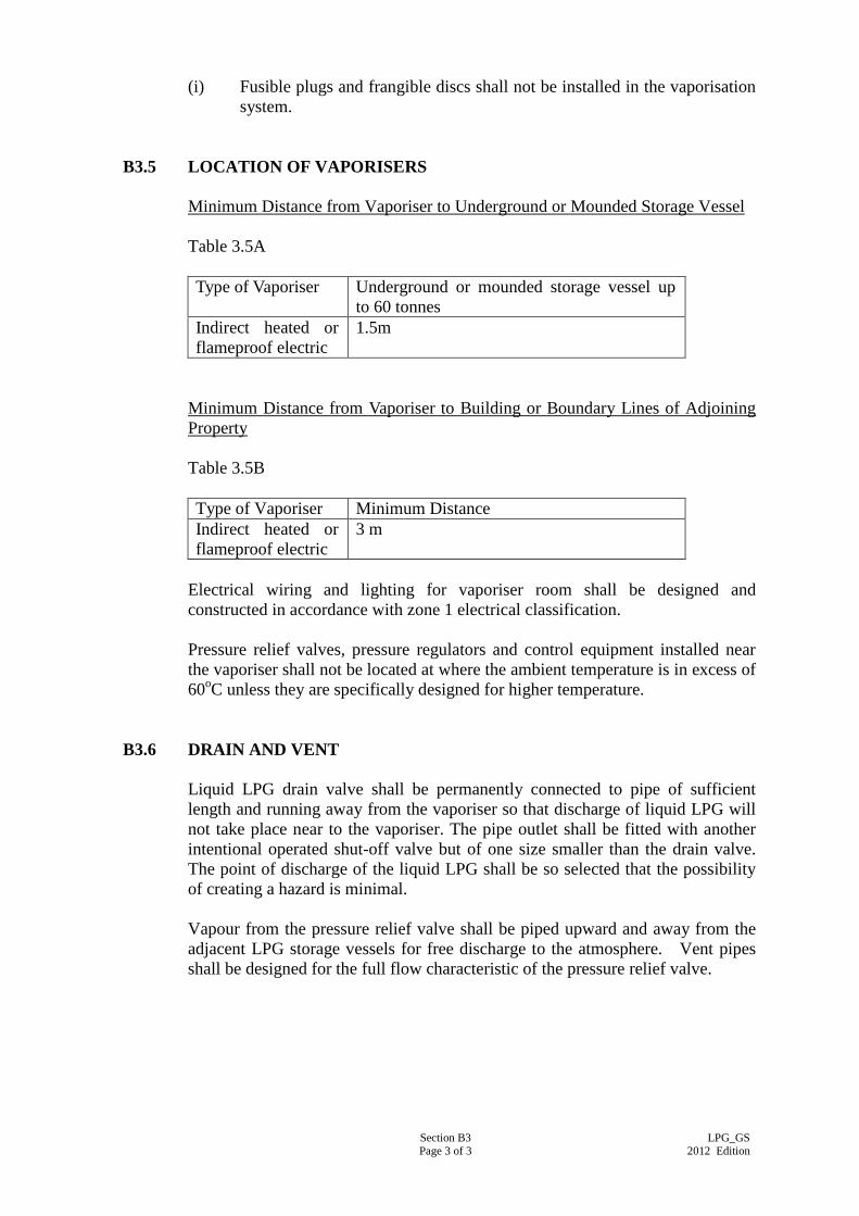
Section B3 Page 3 of 3
LPG_GS 2012 Edition
(i) Fusible plugs and frangible discs shall not be installed in the vaporisation
system.
B3.5 LOCATION OF VAPORISERS
Minimum Distance from Vaporiser to Underground or Mounded Storage Vessel
Table 3.5A
Type of Vaporiser Underground or mounded storage vessel up
to 60 tonnes
Indirect heated or
flameproof electric
1.5m
Minimum Distance from Vaporiser to Building or Boundary Lines of Adjoining
Property
Table 3.5B
Type of Vaporiser Minimum Distance
Indirect heated or
flameproof electric
3 m
Electrical wiring and lighting for vaporiser room shall be designed and
constructed in accordance with zone 1 electrical classification.
Pressure relief valves, pressure regulators and control equipment installed near
the vaporiser shall not be located at where the ambient temperature is in excess of
60oC unless they are specifically designed for higher temperature.
B3.6 DRAIN AND VENT
Liquid LPG drain valve shall be permanently connected to pipe of sufficient
length and running away from the vaporiser so that discharge of liquid LPG will
not take place near to the vaporiser. The pipe outlet shall be fitted with another
intentional operated shut-off valve but of one size smaller than the drain valve.
The point of discharge of the liquid LPG shall be so selected that the possibility
of creating a hazard is minimal.
Vapour from the pressure relief valve shall be piped upward and away from the
adjacent LPG storage vessels for free discharge to the atmosphere. Vent pipes
shall be designed for the full flow characteristic of the pressure relief valve.
Section B4 Page 1 of 4
LPG_GS 2012 Edition
SECTION B4
PIPING AND FITTINGS
B4.1 MATERIAL
All materials shall be compatible for use with LPG under the service conditions
to which they are subjected. Pipes shall be of steel construction complying with
Code of Practice for Hong Kong LPG Industry published by the GasSO.
Materials such as cast iron, aluminium or its alloys, copper, rubber and plastic
other than those specially designed for LPG shall not be used.
LPG mains and service pipes should only be run below ground where this is
unavoidable, and under such circumstance consideration should be given to use
medium density polyethylene pipes instead of steel pipes. Pipework should be
protected from mechanical damage as appropriate.
B4.2 STEEL PIPES
All liquid pipelines shall be Schedule 80 seamless steel pipes conforming to BS
EN 10216-1:2002, BS EN 10217-1:2002 or ANSI/API Spec 5L:2007, and of a
design working pressure of 2.75 MPa.
All vapour pipelines at high pressure stage shall be Schedule 80 seamless steel
pipe conforming to BS EN 10216-1:2002, BS EN 10217-1:2002 or ANSI/API
Spec 5L:2007 or ASTM A53/A53M-10:2010 or equivalent.
All vapour pipelines at medium pressure stage and below shall be of heavy grade
steel construction and conform to BS EN 10255:2004 or ISO 65:1981 heavy
grade or equivalent.
B4.3 FLEXIBLE RUBBER HOSE AND TUBING
The flexible gas hoses and tubings shall be of the type which has been approved
by the Gas Authority. Metallic tubing shall be used if an approved type which
is suitable for the particular application is available. Corrosion resistant braiding
shall be used. Each flexible hose shall be marked with “LPG” and be tagged with
a label indicating the date of next replacement.
Emergency valves shall be installed in all liquid pipelines and in vapour pipelines
at high pressure stage to which the flexible rubber hose are connected, to prevent
discharge of LPG Gas in the event of hose failure. A manual shut-off valve shall
be used for vapour lines designed to operate at medium pressure stage or below.
For installations up to 5kPa, the tubing shall be of minimum practicable length
and shall not exceed 2 metre. The flexible tubing shall not extend from one
room to another nor pass through wall or ceiling etc. and shall be easily
accessible for inspection.
Section B4 Page 2 of 4
LPG_GS 2012 Edition
The end fitting of the flexible rubber hose or rubber tubing shall comply with BS
5315:1991 or the equivalent of applicable codes.
The clips, clamps or spigots used to secure flexible rubber hose or rubber tubing
on the fittings shall be free from burrs and rough edges and shall not be
over-tightened.
B4.4 PIPE JOINTS
Joints in steel pipes of 50 mm nominal bore and smaller shall be welded, or
where approved flanged or screwed. Steel pipe joints over 50 mm nominal bore
shall be welded, or where approved welded flanged. LPG pipes shall be of
welded construction as far as practicable. LPG pipes of flanged or screwed
construction shall have the prior approval of the Architect before installation.
Jointing of steel pipes by electric arc welding shall be in accordance with BS
2971:1991 shall be used on pipes of 15 mm nominal bore or larger.
Jointing compounds for screwed connections shall be resistant to LPG and shall
comply with BS 6956-1:1988, BS 6956-5:1992, BS EN 751-1:1997 and BS EN
751-2:1997. The use of PTEE tape is preferable but lead or hemp shall not be
used.
All underground LPG pipe joints shall be welded unless otherwise approved by
the Architect. Flanged connections shall be kept to a minimum.
B4.5 PIPE FITTINGS
Steel flanges and flanged fittings shall be to ANSI/ASME B 16.5-2009 or BS EN
1759-1:2004 on liquid lines or vapour lines at high pressure stage. Flanges on
vapour lines operating at medium pressure stage or below shall conform to BS
EN 1515-1:2000, BS EN 1092-1:2007. Bolting shall comply with BS EN
1515-1:2000, BS EN 1515-3:2005 or BS 4882:1990 or the equivalent of
applicable codes.
Steel butt-welded fittings shall be to BS EN 10253-1:1999 or at least the same
schedule thickness as the pipes for use at high pressure stage.
Steel socket-welded aid screwed fittings and screwed coupling shall be to BS
3799:1974 or equivalent standard for use at high pressure stage.
Screwed fittings for use with steel pipes to BS EN 10255:2004 or ISO 65:1981on
vapour lines operating at medium pressure or below shall conform to BS 143 &
1256:2000 or BS EN 10241:2000 or the equivalent of applicable codes.
Gaskets shall be resistant to LPG and natural rubber shall not be used.
Screwed union or compression fittings for piping installation within LPG
compound and cylinder store shall be avoided and shall not be used without the
prior approval of the Architect.

Section B4 Page 3 of 4
LPG_GS 2012 Edition
B4.6 ALLOWABLE PRESSURE DROPS
Piping shall be sized that the pressure drop along the medium pressure stage shall
not exceed 7 kPa, and that along the low pressure stage shall not exceed 0.15 kPa.
B4.7 PIPING INSTALLATION
Only lateral pipework inside the premises feeding the gas appliances may be
allowed to be buried in floor slab. They shall be protected against corrosion and
mechanical damage. Installation risers shall be carried external to the building
and exposed or may be enclosed inducts complying with BS 8313:1997.
All pipework shall be properly supported with strong hangers, anchors, brackets,
saddles, guides etc. Pipe supports shall be arranged as near as possible to joints
and changes of direction and each support shall take its share of load.
Supports for steel pipes shall be of mild steel, malleable iron or galvanised steel.
Copper pipes shall be fixed by gunmetal or brass pipe clip. Brackets screwed to
walls shall be secured by expanding plugs or other approved methods. The top
half of the pipe clip shall be detachable without disturbing the fixing. The
maximum distances of pipe supports shall be as shown in Table 4.7A.
Table 4.7A: Spacing of Support for Steel Pipe
Nominal Pipe Size
(mm)
Maximum Distance between Supports (m)
Vertical runs Horizontal runs
20 3 2.5
25 3 2.5
32 3 2.7
40 3.5 3
50 3.5 3
80 4.5 3
100 4.5 3
150 4.5 3
200 4.5 3
Vertical pipe risers shall be adequately supported at the base to withstand the
total weight of the risers and shall be protected against mechanical damage to a
minimum height of 2 metres from ground level.
All vertical and horizontal pipe runs shall have adequate flexibility and facilities
to compensate for thermal expansion and contraction of pipes, or mechanical
stress at branch pipes.
Insulation shall be provided in the pipe support for those sections of piping where
cathodic protection has been provided.
All pipes shall be thoroughly cleaned and wirebrushed to remove all grease, dirt,
rust, scale, and other defects before installation; and shall be protected against
corrosion by wrapping, galvanising or painting as appropriate.
Section B4 Page 4 of 4
LPG_GS 2012 Edition
During the installation work in progress, all open ends of the pipework shall be
blanked off with purposely made plugs or caps to keep foreign matters from
entering the finished system.
Pipework laid in floor slab shall be protected by factory-bonded sheath or
wrapping. The piping shall be covered to a depth of not less than 12 mm. The
channel shall be cleaned of all debris, sharp edges, rubbish and surplus moisture
before the pipe is embedded.
Pipework passing through wall or floors of a building, shall be wrapped and
enclosed in metal sleeve for complete length through the walls or floors and
sealed with a non-combustible sealing agent at both ends. The annular space
between the sleeve and the pipe shall be of sufficient width to allow for the
maximum movement of the pipe due to thermal expansion and contraction. No
joint shall be located within the sleeve. The sleeve shall be of same material as
the LPG piping. Where sleeve passes through a floor that may be wetted or a wall
on which water or corrosive material may condense, the sleeve shall project at
least 25 mm beyond the floor or wall finished surfaces.
A minimum clearance of 150 mm shall be maintained between the LPG pipe and
electric conduits or cables.
Pipework buried underground shall be adequately protected against corrosion and
mechanical damage. Pipework shall be treated with two coats of bituminous paint
and wrapped with corrosion and water resistance self-amalgamating tapes and
mastics, or other equal and approved wrapping for protection against corrosion.
The pipeline channel shall be cleaned of all debris, rubbish and surplus moisture,
and the pipe shall be supported to ensure that it is can be completely surround by
crack free mortar.
Underground pipework outside the premises shall be buried at a depth of not less
than 800 mm. In the case where gas pipes and underground electric cables are
running in a common trench, a minimum clearance of 200 mm shall be
maintained between the two services. Pipe markers shall be fixed to indicate the
route of the buried pipelines.
Underground pipework at road crossing shall have sufficient mechanical
protection to prevent crushing. The LPG Contractor shall submit the detail of
protection for approval before installation.
Section B5 Page 1 of 3
LPG_GS 2012 Edition
SECTION B5
VALVES AND ACCESSORIES
B5.1 GENERAL
Pressure containing metal parts of valves (except appliance valves), including
manual positive shut-off valves, excess-flow check valves, back-flow check
valves, emergency shut-off valves and remotely controlled valves (either
manually or automatically operated), used in piping systems shall be of steel,
ductile iron, malleable iron or brass. Ductile iron shall meet the requirements of
ASTM A 395/ A 395M-99:2009 or equivalent and malleable iron shall meet the
requirements of ASTM A 47/ A 47M-99:2009 or equivalent. All materials used,
including valve seat discs, packing, seals and diaphragms, shall be resistant to the
action of LPG under service conditions.
All diaphragm valves shall be fitted with renewable diaphragms. Back seating
shall be provided to isolate the gland packing when the valve is open for repair or
inspection. Screwed ends shall be to BS EN 10241:2000. Taper threads and
flanged end shall be to BS EN 1759-1:2004 or BS EN 1092-1:2007.
All valves shall be fitted in accessible positions and shall carry clear indication of
the direction of operation required to open and to close the valve. Clockwise
rotation of the lever or spindle shall close the valve.
B5.2 EXCESS FLOW VALVES
Excess flow valves or emergency valves shall be installed in the correct flow
direction and shall intend to close upon excessive discharge of vapour or liquid
resulting from a downstream rupture in hoses and piping system. The flow rate
for closure of the valve shall be substantially above normal service flow rate to
prevent premature closing, but shall in no case exceed 1.5 times the normal
service flow rate.
B5.3 NON-RETURN VALVES
Non-return valves shall be suitable for liquid or vapour use in LPG cylinders/bulk
tanks or in-line application. The valve shall be fitted with soft seat for tight
shut-off so that piping can be blown down for maintenance without leakage.
B5.4 ISOLATING VALVES
Isolating valves shall be of globe type with ductile iron bodies and stainless steel
stems to resist corrosion. The valve seat shall be suitable for long-lived leakproof
service. Steel ball valves shall be to BS EN ISO 17292:2004.
Section B5 Page 2 of 3
LPG_GS 2012 Edition
B5.5 QUICK-ACTING SHUT-OFF VALVES
Quick-acting shut-off valves shall be of lever operation and shall design to close
tight in the direction of arrow.
B5.6 EMERGENCY SHUT-OFF VALVES
A shut-off valve incorporating thermal and manual means of closing provide for
remote means of closing. Emergency shut-off valves shall be provided and
incorporate all of the following means of closing: -
(a) Automatic shut-off through thermal (fire) actuation. When fusible
elements are used they shall have a melting point not exceeding 121 C.
(b) Manual shut-off from a remote location.
(c) Manual shut-off at the installation.
B5.7 PRESSURE RELIEF VALVES
Pressure relief valves shall be spring-loaded and be fully automatic in operation.
The valves shall have an effective rate of upward discharge to protect a system
against excess pressure. The outlet vent connection shall terminate vertically with
a self-detachable weatherproof cap complete with chain at least 3 m above
ground level with an ultimate vertical section of minimum 2 m in length. Clause
B1.3 shall also be referred for pressure relief valves for bulk LPG storage vessel.
Each pressure relief valve shall be plainly and permanently marked with the
following: -
(a) manufacturer’s identification including catalogue or type number;
(b) start to discharge pressure;
(c) certified capacity in terms of air at Standard Temperature and Pressure
(STP).
B5.8 HYDROSTATIC RELIEF VALVES
Hydrostatic relief valves shall be installed in pipelines and hoses located between
isolating valves or blank flanges when liquid LPG can be trapped to protect a
system against excessive pressure caused by thermal expansion of contents. The
pressure relieving device shall be fixed in such a way that it will not discharge
excessive pressure endangering personnel or equipment. The valve shall have a
pressure setting in the range of 2.4 MPa to 2.75 MPa and be fitted with a
self-detachable weatherproof cap complete with chain. The pressure setting
shall not be higher than the weakest element in the system.
Section B5 Page 3 of 3
LPG_GS 2012 Edition
B5.9 PRESSURE GAUGES
Pressure gauges shall have stainless steel case and burden tube with dials not less
than 75 mm diameter. They shall be installed at high, medium and low pressure
stages to indicate the service pressures. Calibration shall be in kPa. Pressure
gauge connections shall be protected by a tapping reduced internally to a bleed
hole not larger than 1.4 diameter or by a suitable excess flow valve and shut-off
valve.
B5.10 METERS
The design, material and construction of meters shall be suitable for the grade of
LPG and the pressure and flow which they are to handle. The meter shall comply
with the relevant parts of BS EN 12405-1:2005 + A2:2010, BS EN 1359:1999,
BS EN 12261:2002 and BS EN 12480:2002 and have corrosion resistant body
and shall be of maintenance-free construction. If the meter is enclosed in a box
for mechanical protection, the box shall be provided with sufficient ventilation.
Section B6 Page 1 of 3
LPG_GS 2012 Edition
SECTION B6
PRESSURE REGULATION
B6.1 PRESSURE RANGES
The ranges of high pressure stage, medium pressure stage and low pressure stage
are as defined in Clause A1.3.
B6.2 CONSTRUCTION OF PRESSURE REGULATORS/GOVERNORS
Pressure regulators/governors shall be compatible for use with LPG in Hong
Kong and designed in accordance with Gas Safety (Gas Supply) Regulation 21.
The material, construction, performance and testing requirements for regulators
of different pressure stages shall conform to BS EN 12864:2001 + A3:2009, BS
EN 13785:2005 + A1:2008 & BS EN 13786:2004 + A1:2008 except otherwise
specified.
All pressure regulators/governors shall be sealed and locked against unauthorized
adjustment after final testing and commissioning.
B6.3 PRIMARY PRESSURE REGULATOR
The primary pressure regulator is used for reducing the system pressure from
high pressure stage to medium pressure stage or directly to low pressure stage.
The medium pressure of the LPG system shall be as specified in the Particular
Specification. The pressure chosen shall not enable the LPG to re-condense due
to fluctuation of ambient temperature. Thermal insulation may be used to prevent
the re-condensation and the insulation shall be impervious to the ingress of water,
resistance to fire and sufficiently robust to withstand minor mechanical damage.
If active-monitor regulator is used, the active regulator shall be of the fail open
type. The monitor regulator shall be of a fail shut type or equivalent and equipped
with an external static connection and shall be set at a slightly higher pressure
than that of the active regulator downstream. The external static connection shall
be connected at a point free of turbulence and preferably at a minimum of 5-pipe
diameter downstream.
All first stage pressure regulating devices shall be located as close as practicable
to the storage vessel or vaporiser and shall also be adequately supported and
easily accessible.
Isolating valves shall be provided to facilitate removal of regulator(s) and shall be
installed as close as practicable to the regulator(s).
Section B6 Page 2 of 3
LPG_GS 2012 Edition
B6.4 SECONDARY PRESSURE REGULATOR
The secondary pressure regulator is used for reducing the system pressure from
medium pressure stage to low pressure stage and shall be capable of maintaining
an outlet pressure of not exceeding 6.9 kPa. The installation shall be fully
protected against effects of both over-pressure and under-pressure downstream
with a need to ensure adequate reliability and continuity of supply.
If the primary pressure regulator is not of the active-monitor type, the secondary
pressure regulator shall be equipped with slam-shut valve, under pressure shut off
(UPSO) and over pressure shut off (OPSO) devices for protection against
regulator malfunctioning.
All secondary pressure regulators and associated protective devices shall be
suitable for outdoor use. They shall be able to work well at overpressure and
underpressure condition and shall normally be installed outside building except
otherwise specified.
B6.5 SERVICE GOVERNOR
The service governor is used to reduce the system pressure from low pressure
stage to the operating pressure of the gas appliances connecting to it and shall be
of spring-loaded type. The outlet pressure of the service governor shall be
adjustable by means of a tool and shall normally be set at 3 kPa except otherwise
specified. The service governor shall be capable of maintaining its outlet pressure
with a maximum fluctuation of 10%.
The service governor shall be suitable for installation on horizontal or vertical
pipe lines.
B6.6 REGULATORS WITH OVER PRESSURE AND/OR UNDER PRESSURE
SHUT OFF DEVICES
The over pressure shut off (OPSO) device shall prevent excessive pressure from
entering a building. The OPSO device shall close automatically and require
manually reset if the regulator outlet pressure rises above a maximum set point.
The under pressure shut off (UPSO) device shall prevent any abnormal low inlet
pressure and/or too great downstream demand. The device shall close
automatically and require manual reset.
The OPSO and/or UPSO device(s) may be integral with a regulator.
Section B6 Page 3 of 3
LPG_GS 2012 Edition
B6.7 REGULATORS/GOVERNORS WITH FULL CAPACITY OF INTERNAL
RELIEF
Regulators/governors equipped with full capacity internal relief valve shall be
capable of limiting the increase of outlet pressure of not more than 7 kPa or the
maximum acceptable operating pressure of gas appliances downstream,
whichever is the lower, even if the regulator is blocked open at full inlet pressure.
The relief valve shall begin to operate at a pressure increase of 2 kPa at the
regulator outlet and shall remain open until the over pressure condition is
relieved.
Vent pipes shall be used to discharge the gas through the internal relief valve to
freely ventilated locations when the escaping gas may constitute a hazard.
Obstruction-free tubing or piping of at least 20 mm diameter shall be used and a
screened vent shall be installed at the end of the vent pipe. On all installation, the
bent or the end of the vent pipe must be protected from anything that may clog it.
Section B7 Page 1 of 2
LPG_GS 2012 Edition
SECTION B7
HAZARD PRECAUTION AND FIRE PREVENTION
B7.1 ELECTRICAL & ELECTROSTATIC HAZARD PRECAUTIONS
Area Classification shall be in accordance with Section 6 of Code of Practice for
HKLPG Industry module 1.
All electrical equipment, apparatus and luminaries to be used in the designed
hazardous area shall comply with the recommendations of BS EN 60079-14:2008
& BS EN 60079-10-1:2009 and shall be of a type suitable for the intended use in
the appropriate zones. The LPG Contractor shall be responsible for providing the
certificates from the appropriate authority for approval before installation. All
electrical equipment shall indicate clearly the type of service for which the
equipment is designed, i.e. intrinsically safe or flameproof, etc.
Electrical wiring for flameproof installations and earthing of the power supply
system shall be in accordance with the General Specification for Electrical
Installation in Government Buildings of the Hong Kong Special Administrative
Region issued by the Architectural Services Department.
With the exception of the insulation which is required to break the continuity of
piping to meet the cathodic protection requirement, the LPG Contractor shall
ensure that all other LPG piping and equipment shall be electrical continuous and
earthed. Continuity tests shall be carried out by the LPG Contractor to the
satisfaction of the Architect.
LPG piping shall not be used as electrical circuit protective conductor or earth
electrode for other systems although their bonding to the circuit protective
conductor may be necessary.
Whenever it is not contradict to the cathodic protection requirement, all bulk
storage vessels shall be electrically earthed to protect against the accumulation of
static electricity.
An earthing terminal shall be provided near the LPG filling point for the
connection of the bulk tanker vehicles. The earthing resistance of the earthing
terminal shall not exceed 1 x 10⁶ ohm for dissipation of static electricity from the
bulk tanker vehicles.
Identification of conductors and cables on LV power circuits shall be in
accordance with the requirements on Cable Colour Code for Fixed Electrical
Installations specified in the Code of Practice for the Electricity (Wiring)
Regulations published by the Electrical and Mechanical Services Department.
Colour tracers may be used, in addition, to distinguish cables one from another.
Section B7 Page 2 of 2
LPG_GS 2012 Edition
B7.2 FIRE PREVENTION AND CONTROL
Fire prevention and control shall be in accordance with UKLPGA Code of
Practice No. 3.
Provision of fire fighting equipment/systems e.g. fire extinguishers, water
drencher, etc., shall be as advised by the Director of Fire Services. The
installation of these equipment/systems shall be in accordance with the General
Specification for Fire Service Installation in Government Buildings of the Hong
Kong Special Administrative Region issued by the Architectural Services
Department.
Fire extinguishers if required to be provided shall be of the type of 3 kg dry
powder fire extinguishers or equivalent at suitable locations in accordance to the
table, unless otherwise specified.
Minimum Number of Fire Extinguishers Required for LPG Compound, Cylinder
Store and Vaporiser Room.
Table B7.2A
LPG Storage Capacity
(Tonnes)
Minimum Number of Fire
Extinguishers Required
LPG Compound (excluding
vaporiser room)
Up to 25
Above 25
2
3
LPG Cylinder Store (excluding
vaporiser room)
Up to 1
1 – 2.5
Above 2.5
1
2
3
Vaporiser room 1
Vessel supports excluding those 450 mm or less in height shall be constructed or
protected to have a standard of fire resistance of at least two hours.
Weeds, long grass and any combustible material should be kept clear from an
area within 3 m of any LPG vessel of up to 2250 litres water capacity and 6 m of
larger vessels. Weed killers containing chemicals such as sodium chlorate, which
are a potential source of fire danger, shall not be selected for this purpose.
Section B8 Page 1 of 4
LPG_GS 2012 Edition
SECTION B8
MISCELLANEOUS
B8.1 GAS DETECTION
Gas leakage or suspected gas leakage shall be checked by the use of a gas
detector, soapy water or by smell BUT NEVER WITH A NAKED FLAME.
Work in the affected or suspected gas leakage areas shall only be resumed subject
to satisfactory gas detector readings.
Inflammable gas detectors shall be used only by Competent Persons.
B8.2 LPG TRANSFER PROCEDURES
The following procedures shall be applied before LPG is transferred from road
tankers to bulk storage vessels: -
Any driving unit or electrical equipment not required and not specifically
designed for the transfer operation shall not be used and be isolated.
Fire extinguishers shall be located in easily accessible positions and temporary
warning notice displayed prominently.
Any accumulated static electricity on a road tanker shall be safety discharged to
the earth terminal provided for this purpose before the LPG transfer connections
are made.
A responsible person of the oil company shall remain both in attendance and
control during all transfer operations to ensure that all the safety operation
measures established by the oil company are enforced.
The road tanker shall be parked in the unloading space and shall be directly under
the water sprinkler or drenching system, if provided.
B8.3 INSTRUCTION, LABELS, SIGNS AND NOTICES
Adequate and appropriate identification labels, emergency instructions, warning
signs and line diagrams shall be provided.
The LPG Contractor shall provide “NO SMOKING”, “LPG HIGHLY
FLAMMABLE” and “LPG STORE” signs in 120 mm minimum English and
Chinese characters and shall prominently display them on or adjacent to each
point of entry to the LPG installation.
At the bulk storage vessels, at least TWO sets of the above mentioned signs shall
be provided. The warning signs shall be made of sandwich plastic material with
white outer layers and a black or red inner layer as required. Lettering shall be
Section B8 Page 2 of 4
LPG_GS 2012 Edition
engraved on the plastic material by cutting away one of the outer layers to outline
the required letters, and exposing the inner underneath. Details shall be
submitted to the Architect for approval prior to engraving.
The LPG Contractor shall provide and install adequate warning signs, emergency
notices, operating instructions and framed schematic and line diagram in
accordance with the requirement of the Gas Authority.
The LPG Contractor shall identify all LPG piping with a colour band in
accordance with BS 1710:1984. The basic identification colour shall be yellow
ochre with black letters and signs on top to show the word “LPG”, the “liquid” or
“vapour” phase where the piping are inside the storage compound and the
direction of flow.
All emergency control/valves shall be labelled to show their ON and OFF
positions. The label may be in the form of a continuous roll of self-adhesive
material or a permanent notice clearly marked “LPG Emergency Valve” and
prominently displayed near such control/valves. Similarly, a permanent notice
marked “LPG Main Control Valve” for the LPG main control valve outside the
building shall also be provided.
Operating instructions shall be provided at appropriate locations to ensure safe,
continuing and reliable operations. The operating instructions shall be made on
a durable material and be properly fixed.
Labels shall be provided to all pipeworks, valves, electric circuits, indicators,
cables, and all other equipment to facilitate operation and proper maintenance of
the installation.
Labels and notices required by statutory requirements shall be inscribed
accordingly whereas other labels shall indicate name and purpose of the equipment
together with ratings where applicable. All labels shall be in both Chinese and
English.
Labels and notices shall be fixed by screws. Where drilling and tapping is
impracticable, approved adhesive may be used subject to prior approval by the
Architect.
Warning notice sufficiently durable and legible throughout the life of the
equipment shall be fixed in a prominent position drawing the attention of the
operator to any potential hazard.
B8.4 PAINTING
Unless otherwise specified or not allowed by the statutory regulations, all
equipment, pipeworks, hangers, brackets, supports, etc. which form part of the
Installations shall be painted after erection. Painting shall be done in accordance
with the latest edition of "General Specification for Building issued by the
Architectural Services Department of the Hong Kong Special Administrative
Region".
Section B8 Page 3 of 4
LPG_GS 2012 Edition
All finishing to factory assembled appliances shall be factory applied in accordance
with the manufacturer’s normal practice and to a standard suitable for the duty and
location of the appliances.
Where factory applied finishes are approved, the LPG Contractor must obtain from
the manufacturer touch-up paint kits and detailed instructions for making good after
completion any damage to finishes which may occur during transportation, storage,
installation or commissioning.
All surfaces, unless otherwise specified, shall be finished in first class paint work.
All metallic surfaces shall be wire-brushed and cleaned to make it free from rust,
scale, dirt and grease prior to painting. All work shall be carried out by
qualified tradesmen. Water based paints with reduced volatile and preservative
content or paints with reduced solvent content formulated for minimal volatile
organic compound emissions complying with reputable international standards
shall be used in occupied areas and renovated areas without good natural
ventilation. In addition, all paints shall contain no mercury, lead, hexavalent
chromium or cadmium compounds. All painting works shall be completed and
left in ventilated environment for at least one week, or the curing period
recommended by the paint manufacturer whichever is longer, before occupation
or handover of the renovated area to minimize volatile organic compound
exposure. All surfaces shall be painted and finished as specified in the
Particular Specification to meet and match the aesthetic architectural design as
required.
Painting shall be of approved type and as described below: -
(a) Do not carry out painting work in wet, humid or foggy weather or on
surface that is not thoroughly dry or if there is excessive dust in the air;
(b) Ensure that all holes, cracks and other defects in surface have been made
good prior to painting;
(c) Ensure the surface is thoroughly clean and dry prior to painting. Loose
material shall be removed by dry brushing with stiff broom or brush;
(d) Keep surface clean and free from dust during coating and drying; and
(e) Protection freshly applied surface coating from damage.
Primer shall be applied to metal surface before the application of under and
finishing coats of paint. Primer for non-galvanised metal surface shall be
metallic zinc-rich primer to BS 4652: 1995, Type 2, and for galvanised surface
shall be calcium plumbate primer or approved etch primer.
The primer, under coat and finishing coat of paint shall be from the same
manufacturer. The painting procedure shall be strictly in accordance with the
manufacturer’s instruction.
For anti-corrosion paint and primer, the correct type of thinner/activator shall be
used and the mixing method shall follow the manufacturer’s instructions.
Section B8 Page 4 of 4
LPG_GS 2012 Edition
The volatile organic compound (VOC) content, in grams per litre, of all paint
applied on surfaces of Liquefied Petroleum Gas Installation and any
installations/equipment inside semi-enclosed/ enclosed areas of the building shall
not exceed :
Type of Internal Paint
Type of External Paint
Water-based Paint : 50g/litre Water-based Paint : 80g/litre
Solvent-based Paint : 400g/litre Solvent-based Paint : 400g/litre
The testing method of the VOC content of paint shall be determined by the US
EPA Method 24.
All finishing to factory assembled appliances shall be factory applied in accordance
with the manufacturer’s normal practice and to a standard suitable for the duty and
location of the appliances.
Where factory applied finishes are approved, the LPG Contractor must obtain from
the manufacturer touch-up paint kits and detailed instructions for making good after
completion any damage to finishes which may occur during transportation, storage,
installation or commissioning.
Section B9 Page 1 of 2
LPG_GS 2012 Edition
SECTION B9
CIVIL WORK
B9.1 LPG COMPOUND
To prevent trespassing or tampering, the LPG compound which houses the
underground or mounded storage vessels, vaporisers, regulators, etc. shall be
enclosed by fence with two means of exit preferably positioned at opposite end of
the compound. The fence shall be of industrial type, at least 1800 mm high and
perforated to maintain good ventilation. The solid concrete kerb for supporting the
perforated fence shall form a bund to a height of not less than 150 mm and not be
higher than 380 mm above finished floor level.
The floor of the LPG compound shall be concreted and those parts underneath the
underground or mounded storage vessels shall be sloped. The vicinity of the
vessels shall also be free from pits and depressions other than those necessary for
drainage or the containment of spillage.
Water drains, where provided, shall be of the U shape with water seal preferably
situated well away from the storage area.
A sterile area of at least 1m shall be provided and paved with concrete around the
LPG compound and conspicuously marked with yellow lines on the floor.
B9.2 ENCLOSURE FOR LPG CYLINDER/PLANT
Rooms containing LPG cylinders/plant shall be well ventilated and made of
non-combustible materials. The floor shall be raised with a higher level than the
surrounding and shall be concreted and sloped down towards an external door
which shall not be provided with kerb. The door shall be open outwards and
shall not be self-locking. The walls, ceilings, roofs and doors (including door
frame and hinge assembly) shall be able to withstand a static pressure of 4.8 kPa.
Those parts common with other structure shall be imperforated and have a fire
resisting period of 2 hours minimum. Drain shall not be provided in the room and
should be avoided in the immediate vicinity i.e. within 3 m of the room. A
sterile area of at least 1 m shall be provided around the cylinder room and
conspicuously marked on the floor with yellow lines.
B9.3 VENTILATION AND EXPLOSION RELIEF APERTURES
The natural ventilation and explosion relief requirements of the room with one
external wall to 4 external walls are provided in Code of Practice for Hong Kong
LPG Industry Module 1. The apertures shall be situated as uniformly as
practicable in the external walls.
Section B9 Page 2 of 2
LPG_GS 2012 Edition
If the requirement for natural ventilation cannot be met, mechanical ventilation
shall be provided.
LPG installations shall be provided with explosion relief apertures located in
external walls, the explosion relief area shall be at least 0.07 m2 per m
3 of
enclosed volume for open vents, or at least 0.1m2 per m
3 of enclosed volume for
louvered vents. A louvered angle shall not be in excess of 45º to horizontal. The
method for calculating the “effective area of ventilation/explosion relief” shall be
in accordance with Code of Practice for HK LPG Industry Module 1.
Imperforated explosion relief panels shall be used. Ventilation apertures may be
included as explosion relief apertures.
LPG cylinders and/or equipment shall not be located within 150 mm of
ventilation apertures. Suitable measures shall be taken to prevent blockage of
ventilation apertures.
B9.4 TRENCHES
Trenches for underground pipe Installations shall have a minimum depth of not
less than 800 mm. There shall be no pebble or small stones at the bottom of the
trench. Electric cables and other services are not permitted to share the same
trench.
B9.5 WALLS, CEILING OR FLOORS
Sleeves of the same material of the LPG piping shall be embedded in holes for
the whole length through walls or slabs. Wall, ceilings, roofs and doors shall be
designed such that if imperforated, they shall be capable of withstanding a static
pressure of at least 4.8 kPa.
B9.6 RADIATION WALLS
Radiation walls for separating the vaporisers and storage vessels /cylinders shall
be substantially constructed of concrete, brick or other suitable material having a
fire resisting period of not less than 2 hours in accordance with BS476 Part 20 –
24:1987. The wall shall not be more than 2.5 m high.
B9.7 WARNING SIGNS AND LABELS
Warning signs and emergency instructions in both English and Chinese shall be
posted by the LPG Contractor near each entrance on the outside wall/fence of the
installation. The size of the letters shall be of 120 mm minimum in height.
Section C1 Page 1 of 8
LPG_GS 2012 Edition
PART C – TECHNICAL REQUIREMENTS FOR APPLIANCES
SECTION C1
LPG GAS APPLIANCES
C1.1 SCOPE OF GAS APPLIANCES
The “Gas appliances” covered in this Section are appliances designed for use by
a consumer of gas for domestic, catering and commercial purposes such as
heating, cooking, hot water supply, lighting, motive power or other ordinary
purposes for which LPG can be used.
C1.2 GENERAL REQUIREMENTS
A gas appliance to be supplied and installed in Hong Kong shall comply with
codes of practices and guidance notes issued by the Gas Authority including
GU03, GU04, GU05, GU06, GU09, GU16 and other codes / guidance notes.
If a gas appliance is primarily designed to be used in domestic premises, it shall
be approved by the Gas Authority and borne the relevant “GU” Mark. Such gas
appliance shall be suitable for operation with LPG of pressure of 2.9 kPa. All
materials used for the construction of the appliance shall be fire and heat
resistance, non-flammable, strong and durable for the expected conditions of
intended service and shall comply with the Gas Safety Ordinance, (Cap. 51).
The gas appliance shall be robust in construction, reliable and efficient in
performance and shall meet the heat output with respect to the fuel input as
specified in the Particular Specification. Apart from the locally fabricated
custom-built cooking appliances, all imported appliances shall comply with the
safety requirements as specified in one of or an equivalent to the following
standards: -
(a) British Standards (BS);
(b) Japanese Industrial Standards (JIS);
(c) Deutscher Verein des Gas and Wasserfaches e.v. (DVGW); and
(d) The safety requirements for the locally fabricated units will be specified
in the Particular Specification or otherwise.
The gas appliance shall incorporate adequate means for the removal of products
of combustion as necessary.
The gas appliance shall incorporate facilities for drawing sufficient permanent
supply of air for proper and efficient combustion.
Section C1 Page 2 of 8
LPG_GS 2012 Edition
The gas appliance and its associated gas fittings shall be stabilized in a secure
position free from damage as affected by the foreseeable environmental dynamic
conditions and accidental factors.
The gas appliance shall incorporate a fine control over the initial release of gas
during ignition phase and shall also be capable of withstanding any undue
explosion within the combustion chamber without damage to any part of the
appliance in the event of ignition delay.
Any gas appliance requiring the supply of water and electricity shall be suitable
for operation under the local supply conditions particularly with respect to the
water pressure at the uppermost floor of the building and electrical voltage, viz.
380 V 3 phase or 220 V single phase 50 Hz.
C1.3 BURNERS AND ASSOCIATED PARTS
Burners shall be made of robust and durable metallic alloy and capable of
producing the maximum heat capacity as specified with the proper mixing of gas
and air.
The burner shall be designed for maximum efficiency, even flame distribution
and generating as little noise as practically allowed.
The main and pilot flames shall be protected against draughts.
The products of combustion when tested in accordance with BS 7977-1:2009
shall not result in a CO/CO2 ratio in excess of 0.02. The CO/CO2 ratio shall not
exceed 0.004 after 5 minutes of operation at normal gas rate.
Ignition may be manual or automatic sparks ignition by means of battery power,
mains electricity, piezo-electric device or electronic device as indicated in the
Particular Specification.
Combustion chamber and heat exchanger if applicable shall be constructed of
high grade thermal conductivity alloy with high heat transfer efficiency.
C1.4 OUTER CASING
The outer casing of the gas appliance shall be smooth with no sharp edges and
insulated from heat transfer such that the contact temperature at any position shall
not exceed the maximum allowable values as specified in BS EN 297:1994.
C1.5 CONTROL AND REGULATING DEVICES
The gas appliance shall incorporate regulating devices for supply of gas, air and
water as applicable.
The inlet gas and air shall be adequately filtered from dirt and dust before being
mixed for combustion. Non-return valves shall be incorporated in the separate
Section C1 Page 3 of 8
LPG_GS 2012 Edition
gas and air stream such that no mixing shall be possible in either supply stream.
C1.6 FORCED DRAUGHT COMBUSTION
If mechanically forced draught is employed for combustion, the flow rate of air
shall be carefully designed and adjusted such that optimum combustion
efficiency is achieved.
The LPG Contractor shall be required to submit calculation verifying his
selection of the blowers, fans, etc. with respect to the burners used in the offered
gas appliance.
Ignition, combustion and air supply shall be properly sequenced for automatic
combustion system for safe and proper purging and such as to avoid the
extinguishments of the pilot or main flame during the course of operation.
C1.7 SAFETY DEVICES
The gas appliance shall incorporate a reliable safety shut-off valve to the gas
supply.
Suitable flame failure device shall be provided to shut off the gas supply by
actuating a relay or solenoid valve if no flame is detected.
Where a thermostat is specified to control the temperature attained in a
compartment of the gas appliance, a back-up overheat protective device shall also
be provided to shut-off the gas supply in the event of failure of the thermostat.
A gas water heating appliance shall be provided with the low water pressure
automatic gas shut-off device.
If a gas appliance is constructed with a built-in power operated flue extract
system, it shall be prevented from operation if the draught fails to operate.
Wherever applicable for a gas heating appliance, safety guards shall be provided
to prevent accidental contact of clothing or inflammable materials with the heat
surfaces.
C1.8 FLAME FAILURE DEVICES AND ASSOCIATED SAFETY SHUT-OFF
VALVES
The flame failure device shall be manufactured to an international acceptable
standard such as JIS S 2103:2010.
Wherever a flame failure device is required, the type of device and its coupling
safety shut-off valves shall be incorporated in the following manner: -
(a) Below 45 kW, thermo-electric type flame failure device may be used;
Section C1 Page 4 of 8
LPG_GS 2012 Edition
(b) 45 kW to 600 kW, electronic type flame failure device coupled with one
safety shut-off valve shall be provided;
(c) 600 kW to 3 MW, electronic type flame failure device coupled with two
safety shut-off valves in line shall be provided;
(d) Above 3 MW, electronic type flame failure device coupled with two
safety shut-off valves in line together with a vent in between the valves
shall be incorporated.
The electronic type flame failure device specified in this Section shall operate on
the principle of current rectification of the flame which in this application shall
rectify an alternating current flowing between an electrode and the burner as the
opposing electrode connected to the ground potential. The rectified signal so
generated shall be amplified to control the operation of a gas relay or solenoid
valve.
The flame failure device shall be installed in a proper position suitable for
performing the required function and sheltered from over-spilling and
over-heating as the circumstances prevail.
C1.9 ASSOCIATED GAS INSTALLATION
All the gas pipework in association with the gas appliance installation shall be
carried out in accordance with Section B4 of this Specification.
All appliances with a fixed flue shall be connected to the gas supply by means of
a permanently fixed rigid pipe.
Flexible rubber tubing complying with Clause B4.4 of this Specification may
only be used for connecting unflued or portable appliances. Each length of
connection shall not exceed 2 m. It shall not extend from one room to another nor
passing through walls, ceilings etc. and shall be easily accessible for inspection
and replacement. Connection to gas pipe by means of integral threaded metal
ends or secured to a gas supply nozzle by crimping or using suitable hose clip as
acceptable. Flexible rubber tubing shall not be exposed to temperature exceeding
50 C.
A gas shut-off valve shall be provided at a readily accessible position at the gas
inlet of the appliance.
C1.10 FLUES
Where a flue is required to be connected to a gas appliance, it shall be
constructed and installed in conformity with BS 5440-1:2008 for a rated input of
up to 70 kW. Flues shall be so designed and constructed as to conduct away the
products of combustion in an efficient manner.
Section C1 Page 5 of 8
LPG_GS 2012 Edition
A flue shall be readily accessible for inspection and maintenance. If it enters a
brick or masonry chimney, access shall be made for inspection and maintenance
of the seal between the flue pipe and the chimney.
Where a flue passes through a tiled or slated roof, the joint shall be weather-proof
by using a purpose-made metal plate with a 150 mm upstand.
Where a flue passes through a ceiling, it shall be fitted with an insulating sleeve.
A flue, if required to be insulated against combustible materials, the surface
temperature shall not reach 65 C. The annular space between the metal sheets
shall be packed with an approved non-combustible material not less than 25 mm
thick.
A flue system incorporating electric powered exhaust draught shall have the
control integrated with the gas appliance such that it shall be prevented from
operation if the draught fails to operate.
If a manually operated damper is incorporated with a flue, it shall always be
maintained in the fixed open position. An automatically operated damper for a
flue shall be interlocked with the gas supply to the burner such that the burner
shall be prevented from ignition in the event of failure of the damper when not in
the open position.
C1.11 TESTING OF GAS APPLIANCE
Gas appliance shall be tested and commissioned in accordance with regulation 30
of Gas Safety (Installation and Use) Regulations and Code of Practice issued by
the GasSO.
The LPG Contractor upon completion of the installation of a gas appliance shall
test the gas connection pipework for soundness. He shall examine the appliance,
the gas fittings and other associated Installations, flue system, condition of
ventilation of the room etc. for the purpose of ascertaining whether
(a) the appliance has been installed to the required standard and regulations;
(b) the appliance has been installed in accordance with the manufacturer’s
instructions;
(c) the safety controls of the appliance are in proper working order; and
(d) the supply gas pressure, water pressure, electrical voltage and frequency
etc. are within the operating range of the gas appliance.
When testing the performance of the appliance, the LPG Contractor shall verify
its satisfactory operation condition with regard to the following aspects: -
(a) the safe functioning of all protective controls;
Section C1 Page 6 of 8
LPG_GS 2012 Edition
(b) the heat output of the appliance as specified in compatible with the fuel
input;
(c) the correct gas/air ratio for proper combustion; and
(d) the effectiveness of the flue extract system.
C1.12 DOMESTIC INSTANTANEOUS TYPE WATER HEATERS
Instantaneous water heaters shall be room sealed, balanced flue type and shall be
so constructed that the combustion air shall be drawn from and the flue gas
conducted away outside the room by means of a concentric wallcase flue duct.
The water heater shall be of modern, compact design and pleasant appearance. It
shall be capable of providing instantaneous hot water with a temperature rise of
25 C at a minimum flow rate as specified in the Particular Specification.
The water heater shall be manufactured to the reputable international standards
such as BS EN 26:1998 or JIS S 2109:2008/Amendment 2:2010. Test certificates
issued by an independent regulatory authority in the country of origin shall be
required unless otherwise approved for use by the Gas Authority.
The water heater shall be approved by the Water Supplies Department for direct
connection to the town mains. Appropriate inlet and outlet pipe fittings shall be
provided for connection to the external pipes. The minimum water supply
pressure required for the water heater shall not be excessive such that it allows
the installation of the water heater at the uppermost floor of the building without
problem.
The water heater shall be equipped with built-in temperature regulator, flame
failure detector, automatic gas shut-off valve, manual regulation valves, pilot
burner and an automatic piezo-electric ignition device unless otherwise specified.
The heat exchanger and combustion chamber shall be constructed of high thermal
conductivity alloy with high heat transfer efficiency.
The fan shape burner shall give even flame distribution with as little noise as
practically allowed.
The outer casing shall be made of heavy gauge sheet metal, properly treated to
prevent rusting and corrosion and finished in high quality white stoved enamel or
equivalent. Any insulation materials used shall be free of asbestos.
The inlet pipe connections shall be arranged in such manner that the gas pipe
shall be preferably positioned between the hot and cold water pipes.
Balanced flue/room-sealed water heaters shall be installed in purpose built flue
aperture, the location of which shall comply with the Building (Planning)
Regulation 35A and the Practice Note to Authorized Persons issued by the
Building Authority.
Section C1 Page 7 of 8
LPG_GS 2012 Edition
The water heater shall be installed on the wall by means of a number of
substantial bolts and nuts. The process of fixing the heater in position shall not
impair the supporting structure. The indoor portion of the appliance shall be
installed to allow sufficient clearance from the side walls, ceiling and other
structures for maintenance or replacement. The flue duct shall be adjusted to
allow effective rejection of flue gases and, if for balanced flue, to allow also
sufficient inlet vents for the intake air for combustion. The portion of flue duct
passing through the external wall shall be thermally insulated and sealed for
weather proofing. All ducts and pipes shall be checked for cleanliness and
clearance of obstacle prior to commissioning.
Fan assisted room sealed instantaneous water heater shall be provided where
specified in the Particular Specification. The fan assisted heater shall be
complete with built-in flue fan. The flue fan shall have an over-run time before
the ignition and after shutting down of the burner in accordance with the
applicable design code. The electric fan, wirings and all parts of electrical
installation of the heater shall comply with the requirements of the Electricity
(Wiring) Regulations and suitable for electricity supply of 220V a.c., 50 Hz. The
heater shall either have a viewing window for the user to check at any time that
the heater is in operation by visual observation of the flame or have an indication
lamp indicating the heater is on.
Terminals for earthing or equipotential bonding shall be provided where
applicable.
C1.13 DOMESTIC TYPE GAS COOKER
The gas cooker shall be of modern design, pleasant appearance and suitable for
installation in domestic kitchen. Facilities shall contain an oven, hot plates and a
grill of various ratings as specified in the Particular Specification.
The gas cooker shall comply with BS EN 30-1-2:1999, BS EN 30-1-3:2003 or
BS EN 30-2-2:1999 and Code of Practice GU05 relevant for use with LPG.
Unless otherwise specified, the cooker shall comprise open ring burners for the
hot plates and jet burners for both the oven and grill.
All burners shall give low noise level in operation and a minimum noise in
turning off to extinguish. All burners shall be regulated by “push and turn”
control knobs; stable flames shall be maintained at all knob’s position. All
burners shall be suitable for simmering by adjusting the control knobs.
Unless otherwise specified, the oven shall be of the internally heated type with
side hinged door. The oven shall be equipped with a temperature control
regulator by means of thermostat with back-up overheat gas shut-off device. A
flame failure device shall be fitted to shut-off the gas supply in the event of
failure of the pilot or main flame.
Solid top hot plates if specified shall be fitted with flame failure device.
Section C1 Page 8 of 8
LPG_GS 2012 Edition
Unless otherwise specified, the grill shall be of the open-fired type with the
source of heat radiated from a metal fret above the food.
Ignition means to the various cooking facilities shall be specified in the Particular
Specification or otherwise it will be assumed to be all manual without the use of
a spark gun and to the manufacturer’s standard product. Battery if required
shall be included.
Means shall be provided to cater for spillage from the burner and the spill
receivers shall be designed for easy cleaning.
A storage compartment with door beneath the oven shall be provided. Means of
levelling the cooker shall also be available.
The casing shall be made of heavy gauge sheet metal properly treated to prevent
rusting and corrosion and finished in high quality white or cream vitreous enamel
or acceptable equivalent. The casing shall be insulated internally.
The cooker shall be supplied with a standard baking tray, a roasting tin and a ring
type wok adaptor suitable for 300 mm diameter nominal size Chinese Wok.
The cooker shall be positioned at sufficient distance from the adjacent wall,
overlaying shelves or other appliances or structures to prevent overheating of the
surrounding. It shall be installed and commissioned all in accordance with the
manufacturer’s instructions.
Section D1 Page 1 of 10
LPG_GS 2012 Edition
PART D – INSPECTION, TESTING AND COMMISSIONING
SECTION D1
INSPECTION, TESTING AND COMMISSIONING
D1.1 General
After the installation work is completed, the LPG Contractor shall test and
commission the whole installation for proper and safe operation.
The testing and commissioning of the installation shall be carried out by
Competent Persons of the LPG Contractor according to the Specification and the
manufacturer’s instruction and manuals. The LPG Contractor shall follow
relevant approved standards, procedures, guidelines in the testing and
commissioning works. They shall include but not limited to :
(a) Statutory Obligations and other requirements, Specifications and Standards
specified in Part A;
(b) Testing and Commissioning Procedure for Liquefied Petroleum Gas
Installation in Government Buildings of the Hong Kong Special
Administrative Region;
(c) Code of Practice for HKLPG Industry Module 1;
(d) Detailed inspection, testing and commissioning methods and procedures
approved by the Architect;
(e) Manufacturers’ recommendation and specifications; and
(f) Test requirements under various standards including British Standards,
European Standards, ISO Standards and other International Standards on
Liquefied Petroleum Gas Installation.
The LPG Contractor shall submit detailed testing and commissioning procedures
and programme for approval by the Architect prior to the testing and
commissioning of the LPG installation. The procedures include all the
requirements in LPG_TCP with other additional requirements for the installation.
The LPG Contractor shall carry out safety test and functional test for the
installation. The LPG Contractor shall commission the installation and carry
out complete performance tests for all equipment and systems installed by him in
accordance with the manufacturer’s instructions, the requirements of the statutory
rules and regulations and to the satisfaction of the Architect. The tests shall
include, but not limited to :-
(a) factory tests where required;
(b) visual inspection and checking;
Section D1 Page 2 of 10
LPG_GS 2012 Edition
(c) safety tests;
(d) commissioning, tuning and adjustment;
(e) functional tests; and
(f) performance tests.
All tests mentioned in Clauses from D1.2 to D1.12 shall be witnessed and
certified by a “Competent Person” as defined in Section A1. The LPG
Contractor shall despatch competent and experienced commissioning engineers
and technicians to carry out the testing and commissioning of the installation.
The LPG Contractor is required to appoint a competent and experienced
commissioning engineer responsible for the overall planning, organizing,
coordinating, supervising and monitoring of the testing and commissioning works
and also certifying all results and reports from the testing and commissioning
works. The LPG Contractor shall submit, at the commencement of the Contract,
information detailing the qualification and experience of the commissioning
engineer for the Architect’s approval. The commissioning engineer shall be a
"Competent Person" as defined in Section A1 and has minimum 3 years on-site
experience in similar type and scale of testing and commissioning works.
All labour, instrument, fuel and materials necessary for carrying out the tests and
for commissioning shall be provided by the LPG Contractor.
Before the testing and commissioning of the LPG installation, the Competent
Person shall check and ensure that the fire protection system for the LPG
installation, if provided, should have been tested and accepted by Fire Services
Department and put into operation.
The LPG Contractor shall ensure Approval of Use has been obtained from Gas
Authority before filling up the LPG storage tank or supplying LPG cylinders for
commissioning of the LPG installation. The LPG Contractor shall submit
relevant information, test certificates and drawings to the Architect for applying
Approval of Use from the Gas Authority well before commissioning of the LPG
installation. All submission fees, if any, shall be borne by the LPG Contractor.
The LPG Contractor shall ensure all tests are completed and certified by the
Competent Person before forwarding the relevant information to the Architect for
applying Approval of Use.
Prior to testing and commissioning, the LPG Contractor shall submit detailed
procedures and a programme for testing and commissioning to the Architect for
approval.
The LPG Contractor shall make arrangement with the Gas Authority for
inspection and witness of the tests, including the pressure test and ‘holiday test’
for the underground pipeline and storage tanks, prior to cover up/back-filling.
Prior to the test, the LPG Contractor shall carry out commissioning which shall
include but not limited to :-
Section D1 Page 3 of 10
LPG_GS 2012 Edition
(a) All equipment, joints, valves, etc. shall be checked for leakage, integrity
and proper function;
(b) Pressure regulators shall be set to their lowest outlet pressure initially
and gradually adjusted to their required operating pressures. The
regulators shall be checked for their pressure control function over the
entire range of the design conditions including shut-off capability;
(c) LPG trap shall be checked to ensure it is filled with water;
(d) Active and monitor regulators shall be set for the designed function; and
(e) Vaporiser including the heat and level controls shall be checked for
satisfactory operation.
D1.1.1 Master Programme of Testing and Commissioning Works
The LPG Contractor is required to submit a programme for testing and
commissioning works which shall be submitted at the commencement of
the Contract, usually within the first three months. The programme
shall indicate the tentative dates of all tests and commissioning works
that will be carried out throughout the whole Contract and all necessary
submissions and approval relating to testing and commissioning and
ensure that the testing and commissioning programme matches the
master programme for construction and that all testing and
commissioning works are complete before the completion date of the
Contract.
A detailed checklist of all the equipment and installation of the Works to
be commissioned and tested shall be submitted at the same time. The
checklist will be used for progress monitoring and shall be updated from
time to time as the Works progress towards completion.
The testing and commissioning programme submitted by the LPG
Contractor shall detail the type of testing and commissioning works
required, the breakdown of the programme into area-by-area basis, the
tests that are required during construction and before completion of the
Works, the period of each test with float time allowed, and the proposed
programme for the completion of builder’s works. Critical path
programme shall be submitted. The LPG Contractor shall plan the
programme so as to minimise the overlapping of different tests arranged
simultaneously in different locations of the Site.
D1.1.2 Inspection, Testing and Commissioning Methods and Procedures
The LPG Contractor is required to submit detailed inspection, testing and
commissioning methods and procedures together with report formats for
reporting inspection, testing and commissioning results for the
Architect’s approval at least 4 months before commencement of testing
and commissioning works, or 4 months after the commencement of the
Section D1 Page 4 of 10
LPG_GS 2012 Edition
Contract, whichever is earlier.
Submission for works to be tested and commissioned during the
construction period shall be made in good times matching with the
construction programme for approval. For tests that have to be done
satisfactorily before subsequent construction work, such tests shall be
completed to the approval of the Architect before new construction work
is to be carried out.
The LPG Contractor shall submit detailed inspection, testing and
commissioning methods and procedures following the format in
LPG_TCP adding additional pages and details in accordance with the
manufacturers’ recommendation and relevant standards, and adding
testing and commissioning procedures for systems and equipment not
covered in LPG_TCP.
D1.1.3 Labour and Materials
The LPG Contractor is required to be responsible for provision of all
labour and both consumable and non-consumable materials for carrying
out testing and commissioning works at their expenses. Electricity
supply, water, LP gas, town gas and other fuel for carrying out of testing
and commissioning works shall also be arranged and provided by the
LPG Contractor at no cost to the Employer. Where specified, Building
Contractor may supply electricity and water.
The LPG Contractor shall provide, at no cost to the Employer, all
necessary equipment, apparatus, tools and materials for carrying out of
testing and commissioning works.
The LPG Contractor shall properly drain the water and exhaust the gases
during and after the test as required. The LPG Contractor shall provide
and adopt measures to avoid damage to the building, installations,
decorations and fixtures during the tests.
The LPG Contractor shall allow labour, materials and fuel for carrying
out overall acceptance test with the users and maintenance agents, and to
provide training to the users and operators on the use and operation of the
equipment.
D1.1.4 Supply of Inspection, Measuring and Testing Equipment
The LPG Contractor is required to supply the calibrated equipment and
instrument for testing and commissioning works in accordance with the
requirements as specified in the Particular Specification.
Section D1 Page 5 of 10
LPG_GS 2012 Edition
D1.1.5 Readiness for Testing and Commissioning
The LPG Contractor is required to check the completion of the works to be
tested or commissioned, the associated builder’s works and the associated
building services installations to ensure that testing and commissioning
can be proceeded in a safe and satisfactory manner without obstruction.
D1.1.6 “Type-test” Certificate
“Type-test” for equipment shall be carried out at the manufacturers’
works or elsewhere appropriate in order to demonstrate their compliance
with the Regulation or requirements. “Type-test” certificates together
with the corresponding drawings, sketches, reports and any other
necessary documents shall be submitted to the Architect for approval
before delivery of the equipment.
D1.1.7 Notice of Inspection, Testing and Commissioning Works
The LPG Contractor is required to provide advanced notice for inspection,
testing and commissioning works as follows:
(a) Off-site Inspection and Testing
An advanced notice of at least one week before commencement of
the inspection or test shall be provided.
(b) On-site Inspection, Testing and Commissioning
An advanced notice of at least 4 days before commencement of
inspection, testing or commissioning shall be provided.
The LPG Contractor shall plan the testing and commissioning
programme to enable the Architect or his representatives to witness all
the tests. Unless otherwise approved by the Architect, testing and
commissioning works carried out by the LPG Contractor in the absence
of the Architect or the Architect’s representatives shall not be accepted
as the approved contract test record.
D1.1.8 Documentation and Deliverables
The LPG Contractor shall record all commissioning information and
testing results at the witness of the Architect or his representatives.
Testing and commissioning shall be properly checked and certified by
LPG Contractor’s commissioning engineer and signed by the Architect or
his representative who has witnessed the testing or commissioning before
submission to the Architect. The LPG Contractor shall submit full
testing and commissioning report to the Architect within 14 days after
completion of testing and commissioning of the installation.
Section D1 Page 6 of 10
LPG_GS 2012 Edition
Immediately after each test, the commissioning engineer shall sign the
test/data record sheet, and obtain the endorsement of the Architect’s
representative who has witnessed the test on site, irrespective of whether
the test is successful or not, and submit a copy of the test/data record
sheet to the Architect. For testing that is required during the
construction period, the LPG Contractor shall also submit a formal
testing and commissioning report endorsed by the commissioning
engineer within 14 days after the completion of the whole test for any
part of the installation.
3 copies of the results of tests for all appliances and certificate of tests for
pressure type appliances and certificates for gas appliances signed by
authorised or competent person shall be submitted before the hand-over
inspection and shall be included in the related operation and maintenance
manuals.
D1.2 BULK LPG STORAGE VESSELS
LPG storage vessels should be tested and certified by a Competent Person to
prove that the vessel is up to the required standard: -
(a) Ultrasonic/radiographic tests for examining internal flaws in accordance
with the applicable design code; and
(b) Magnetic particle or penetrant tests for examining surface flaws in
accordance with BS EN ISO 17638:2009 and BS EN ISO 23278:2009.
In addition, the following tests shall be carried out on site by the LPG Contractor:
-
(a) Hydraulic test at testing pressure 1.5 times of the design pressure of the
storage vessels;
(b) Commissioning pneumatic test at 700 kPa or 90% of design pressure,
whichever is lower;
(c) Paint thickness test (400m minimum);
(d) For underground vessels, “holiday” test after the vessel is coated; and
(e) Leak test for the connections up to a minimum pressure of 689 kPa.
Format of the test certificate shall follow Code of Practice for Hong Kong LPG
Industry Module 1 issued by the GasSO.
D1.3 VAPORISERS
Vaporisers and associated relief valves shall be hydraulic tested and certified by a
Competent Person at 1.5 times of the design pressure. The components of the
Section D1 Page 7 of 10
LPG_GS 2012 Edition
vaporiser not capable of accepting the test pressure shall be isolated or removed
whichever appropriate during the hydraulic test.
Satisfactory operation of liquid control and heat input control device shall be
checked.
Flame failure devices, pilot and main burner systems shall be checked and
adjusted to give satisfactory and safe operation.
For indirect heated vaporiser using water as heating medium, water level safety
controls shall be checked for proper operation.
Format of the test certificate shall follow Code of Practice for Hong Kong LPG
Industry Module 1 issued by the GasSO.
D1.4 PIPEWORK TESTING
All pipework shall be tested after construction and before being placed in
operation to ensure that it is structurally sound and gas-tight. In carrying out the
test, precautions shall be taken to protect against any dangers which may arise if
such pipe fails the test. : -
(a) the person carrying out the test;
(b) any persons working in the vicinity; and
(c) members of the public.
All pipework shall be pressure tested as follows: -
(a) All liquid lines shall be hydraulically tested at 1.1 times the HRPV setting
after isolation of elements that could be damaged by the test pressure.
Pressure test certificates shall state HRPV setting in addition to hydraulic
test pressure. After the hydraulic test is completed, all isolated elements
shall be properly installed and the whole system shall be tested
pneumatically at a minimum pressure of 689 kPa;
(b) High pressure vapour lines shall be tested either pneumatically or
hydraulically at a minimum pressure of 1034 kPa; and
(c) Medium and low pressure vapour lines shall be tested either
pneumatically or hydraulically at a minimum pressure of 103 kPa and
69 kPa respectively.
Time shall be allowed for temperature stabilization during pressure testing. The
line pressure shall be adjusted to the test pressure after stabilization.
Note: The time allowing for temperature stabilization depends on the ambient
temperature, test medium, pipe size and length. Generally this shall not be less
than 15 minutes.
Section D1 Page 8 of 10
LPG_GS 2012 Edition
For pneumatic testing, the test shall be undertaken in phases as follows: -
(a) Initially pressurize the system to 140 kPa and hold it for sufficient time to
ensure that all fittings have been adequately fastened;
(b) The pressure shall then be raised in stages until the required test pressure
is reached; and
(c) After each pressure increase, sufficient time shall be allowed to ensure
system integrity.
All exposed pipework shall be subject to annual visual examination and leak test
using soap solution.
For hydraulic and pneumatic pressure test, the test period shall be of a minimum
of 30 minutes and there shall be no sign of pressure decay during this period.
Note: Pressure decay indicates leakage and leaks shall then be identified by sight
and sound or soap solution.
All open ends of a piping system shall be suitably blanked before testing.
Pipework pressure tests shall be recorded and the test report shall include the
following: -
(a) name of LPG Contractor, and signature of the Competent Person who
supervise the tests;
(b) test date;
(c) maximum working pressure;
(d) test pressure, medium and duration;
(e) test results; and
(f) material, rating and specification of pipework and fittings.
The pressure of the pipework shall be reduced to zero as soon as is practicable
after the pressure tests (see Gas Safety (Gas Supply) Regulation 20). Upon
satisfactory completion of pressure tests, the pipework shall be purged into
service in accordance with Section D1.12 prior to commissioning and operation
of the LPG installation.
Format of the test certificate shall follow Code of Practice for Hong Kong LPG
Industry Module 1 issued by the GasSO.
D1.5 REGULATORS
Regulators shall be checked for the required pressure control functioning over the
required range of flows and for tight shut-off at zero flow.
Section D1 Page 9 of 10
LPG_GS 2012 Edition
D1.6 EMERGENCY VALVES
All emergency valves shall be checked for proper functioning.
D1.7 PRESSURE RELIEF VALVES
(a) Pressure relief valves shall be calibrated and sealed by the manufacturer
of the Competent Person before installation; and
(b) Check shall be carried out to ensure that relief valve vent caps are in place
and mobile.
D1.8 VESSEL CONTENT GAUGES AND FIXED MAXIMUM LIQUID LEVEL
DEVICES
Vessel content gauges and fixed maximum liquid level devices shall be checked
for correct functioning and accuracy.
D1.9 GAUGES
Gauges shall be checked for accuracy and proper functioning.
D1.10 EARTHING
Installation earthing shall be tested and test results shall be submitted.
D1.11 CATHODIC PROTECTION SYSTEM
The cathodic protection system shall be tested and test results shall be submitted.
It shall be checked at intervals not exceeding 6 months.
D1.12 PURGING/GAS FILLING OF VESSELS AND SYSTEMS
The method and procedure for purging or gas filling of vessels and systems shall
be in accordance with the Code of Practice for HKLPG Industry Module 1.
D1.13 THE GAS AUTHORITY INSPECTIONS AND WITNESS OF TESTS
Additional tests and inspections, where not specified above, shall also be carried
out to meet the statutory requirements to the satisfaction of the Gas Authority.
The LPG Contractor shall make all necessary applications to the Gas Authority
and attend to the inspections conducted by their representatives for the purpose of
these tests and inspections.

Section D1 Page 10 of 10
LPG_GS 2012 Edition
D1.14 TESTING AND COMMISSIONING REPORT
A testing and commissioning report shall be forwarded to the Architect within
14 days after completion of testing and commissioning the installation.
Section E1 Page 1 of 4
LPG_GS 2012 Edition
PART E – INSPECTION, ATTENDANCE, OPERATION AND
MAINTENANCE DURING MAINTENANCE PERIOD
SECTION E1
MAINTENANCE
E1.1 GENERAL MAINTENANCE REQUIREMENTS
The LPG Contractor shall furnish maintenance at no cost to the Employer for the
complete LPG installation in the Contract for the whole Maintenance Period or
any section or part thereof certified by the Architect. This maintenance shall
include the following services: -
(a) Emergency inspection, testing and repair;
(b) Routine maintenance including preventive maintenance services;
(c) Quarterly inspection, testing and servicing;
(d) Annual and final inspection, testing and servicing; and
(e) All the services and requirements in Section E1.
The maintenance of the LPG installation shall be carried out by Competent
Person of the LPG Contractor in accordance with the Code of Practice for
HKLPG Industry Module 1, this specification and the manufacturers’ instructions
and manuals. All inspections, tests, servicing and repairs shall be carried out to
the satisfaction of the Architect.
The LPG Contractor shall despatch competent and experienced engineers and
technicians equipped with appropriate testing instruments, tools, equipment, etc.
to inspect, service, test, adjust and maintain the LPG installation in a satisfactory
and safe operating condition.
The LPG Contractor shall allow for carrying out 24-hour emergency and routine
maintenance work at a time outside normal office hours including general
holidays whenever necessary. The LPG Contractor shall allow and prepare to
provide a high level of service for the prompt rectification of the faults especially
those related to safety issues.
All labour and materials necessary and transportation required for carrying out
routine and emergency inspections, tests, repairs, replacements and maintenance
services shall be included in the Contract. During the Maintenance Period, the
LPG Contractor shall supply and install at no cost to the Employer replacements
for all equipment and parts which in the opinion of the Architect become
unserviceable where such unserviceability is due to faulty materials,
workmanship, design or installation or inadequate performance, rating and size of
the Work provided by the LPG Contractor. The LPG Contractor shall also be
responsible to replace all Liquefied Petroleum Gas which may be lost by leakage
or become unserviceable due to the aforesaid reasons.
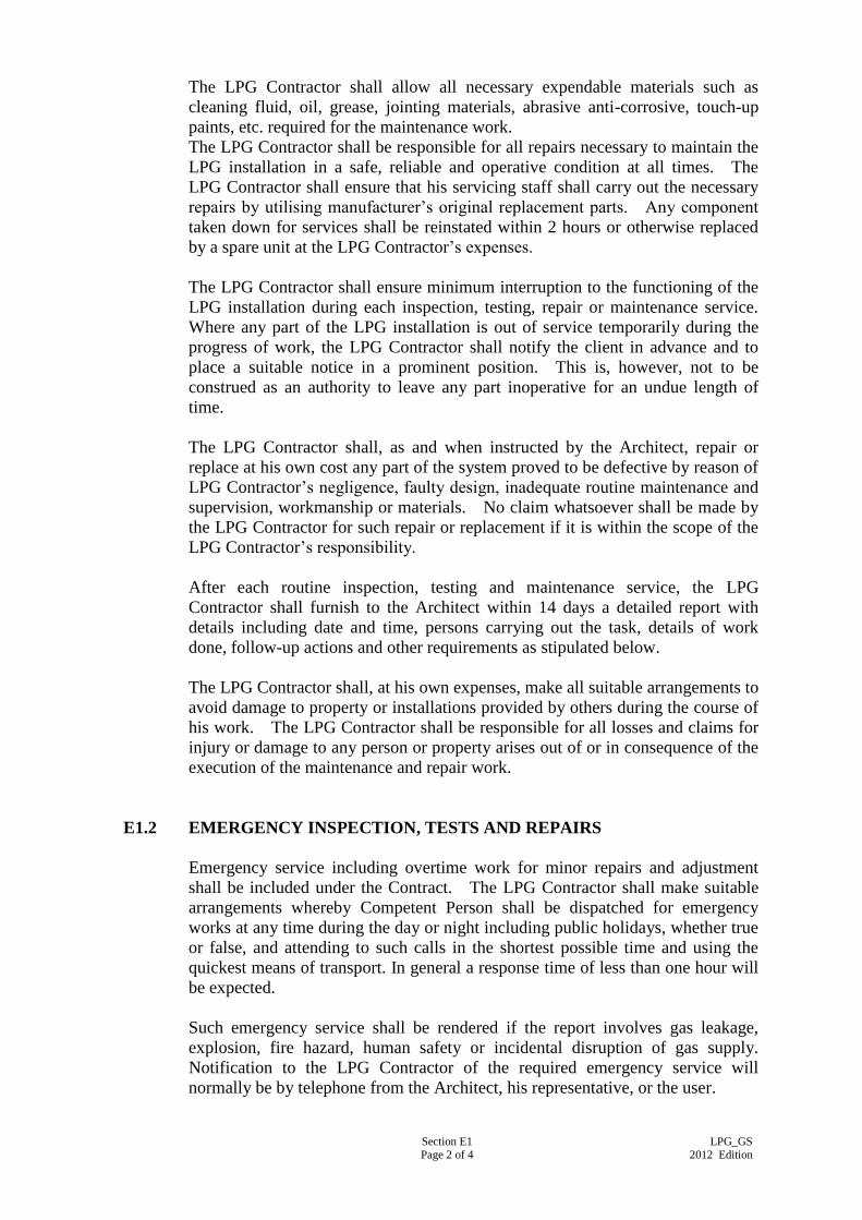
Section E1 Page 2 of 4
LPG_GS 2012 Edition
The LPG Contractor shall allow all necessary expendable materials such as
cleaning fluid, oil, grease, jointing materials, abrasive anti-corrosive, touch-up
paints, etc. required for the maintenance work.
The LPG Contractor shall be responsible for all repairs necessary to maintain the
LPG installation in a safe, reliable and operative condition at all times. The
LPG Contractor shall ensure that his servicing staff shall carry out the necessary
repairs by utilising manufacturer’s original replacement parts. Any component
taken down for services shall be reinstated within 2 hours or otherwise replaced
by a spare unit at the LPG Contractor’s expenses.
The LPG Contractor shall ensure minimum interruption to the functioning of the
LPG installation during each inspection, testing, repair or maintenance service.
Where any part of the LPG installation is out of service temporarily during the
progress of work, the LPG Contractor shall notify the client in advance and to
place a suitable notice in a prominent position. This is, however, not to be
construed as an authority to leave any part inoperative for an undue length of
time.
The LPG Contractor shall, as and when instructed by the Architect, repair or
replace at his own cost any part of the system proved to be defective by reason of
LPG Contractor’s negligence, faulty design, inadequate routine maintenance and
supervision, workmanship or materials. No claim whatsoever shall be made by
the LPG Contractor for such repair or replacement if it is within the scope of the
LPG Contractor’s responsibility.
After each routine inspection, testing and maintenance service, the LPG
Contractor shall furnish to the Architect within 14 days a detailed report with
details including date and time, persons carrying out the task, details of work
done, follow-up actions and other requirements as stipulated below.
The LPG Contractor shall, at his own expenses, make all suitable arrangements to
avoid damage to property or installations provided by others during the course of
his work. The LPG Contractor shall be responsible for all losses and claims for
injury or damage to any person or property arises out of or in consequence of the
execution of the maintenance and repair work.
E1.2 EMERGENCY INSPECTION, TESTS AND REPAIRS
Emergency service including overtime work for minor repairs and adjustment
shall be included under the Contract. The LPG Contractor shall make suitable
arrangements whereby Competent Person shall be dispatched for emergency
works at any time during the day or night including public holidays, whether true
or false, and attending to such calls in the shortest possible time and using the
quickest means of transport. In general a response time of less than one hour will
be expected.
Such emergency service shall be rendered if the report involves gas leakage,
explosion, fire hazard, human safety or incidental disruption of gas supply.
Notification to the LPG Contractor of the required emergency service will
normally be by telephone from the Architect, his representative, or the user.
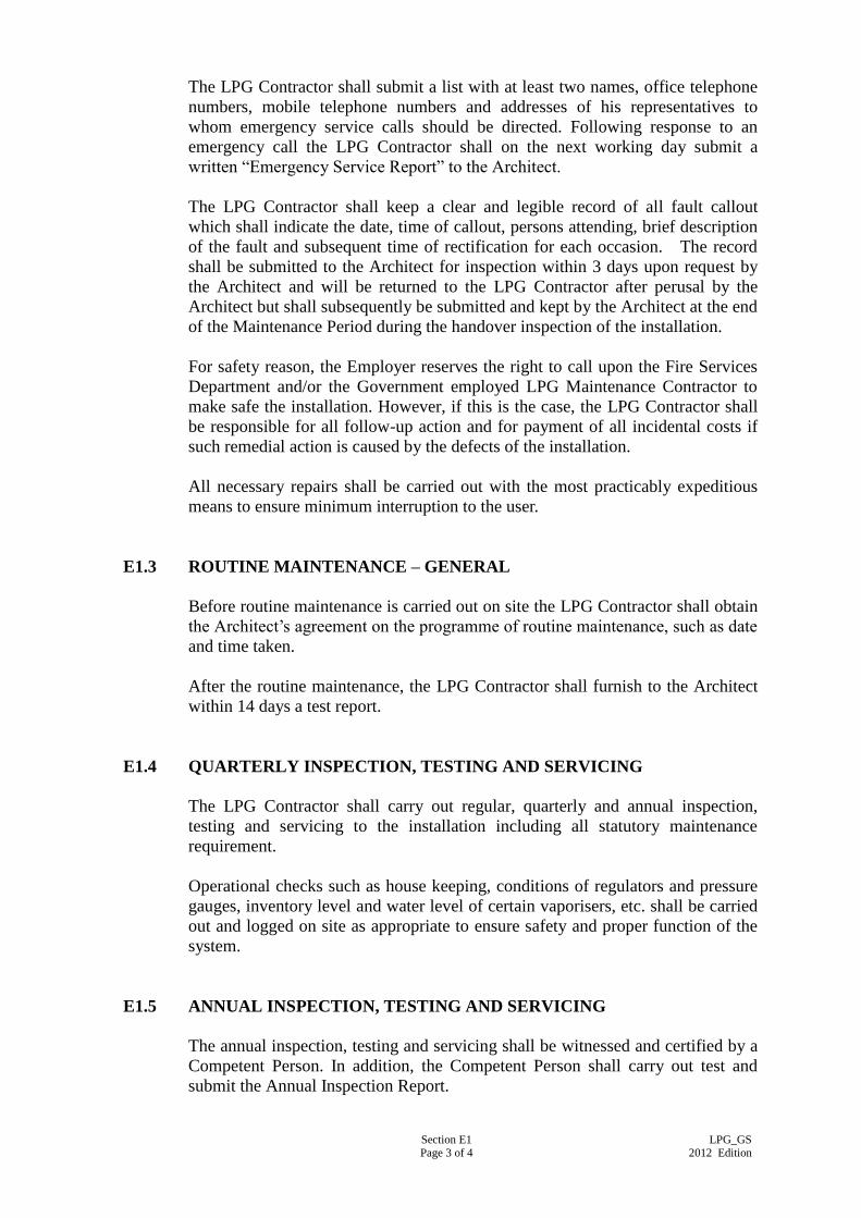
Section E1 Page 3 of 4
LPG_GS 2012 Edition
The LPG Contractor shall submit a list with at least two names, office telephone
numbers, mobile telephone numbers and addresses of his representatives to
whom emergency service calls should be directed. Following response to an
emergency call the LPG Contractor shall on the next working day submit a
written “Emergency Service Report” to the Architect.
The LPG Contractor shall keep a clear and legible record of all fault callout
which shall indicate the date, time of callout, persons attending, brief description
of the fault and subsequent time of rectification for each occasion. The record
shall be submitted to the Architect for inspection within 3 days upon request by
the Architect and will be returned to the LPG Contractor after perusal by the
Architect but shall subsequently be submitted and kept by the Architect at the end
of the Maintenance Period during the handover inspection of the installation.
For safety reason, the Employer reserves the right to call upon the Fire Services
Department and/or the Government employed LPG Maintenance Contractor to
make safe the installation. However, if this is the case, the LPG Contractor shall
be responsible for all follow-up action and for payment of all incidental costs if
such remedial action is caused by the defects of the installation.
All necessary repairs shall be carried out with the most practicably expeditious
means to ensure minimum interruption to the user.
E1.3 ROUTINE MAINTENANCE – GENERAL
Before routine maintenance is carried out on site the LPG Contractor shall obtain
the Architect’s agreement on the programme of routine maintenance, such as date
and time taken.
After the routine maintenance, the LPG Contractor shall furnish to the Architect
within 14 days a test report.
E1.4 QUARTERLY INSPECTION, TESTING AND SERVICING
The LPG Contractor shall carry out regular, quarterly and annual inspection,
testing and servicing to the installation including all statutory maintenance
requirement.
Operational checks such as house keeping, conditions of regulators and pressure
gauges, inventory level and water level of certain vaporisers, etc. shall be carried
out and logged on site as appropriate to ensure safety and proper function of the
system.
E1.5 ANNUAL INSPECTION, TESTING AND SERVICING
The annual inspection, testing and servicing shall be witnessed and certified by a
Competent Person. In addition, the Competent Person shall carry out test and
submit the Annual Inspection Report.

Section E1 Page 4 of 4
LPG_GS 2012 Edition
E1.6 HANDOVER OF LIQUEFIED PETROLEUM GAS INSTALLATION
The LPG installation will not be deemed as acceptable for handover to the
Architect until the installation is in good working order and all as-built drawings,
instruction and maintenance manuals, spare part list, test reports, test certificates,
etc. have been submitted to the Architect.
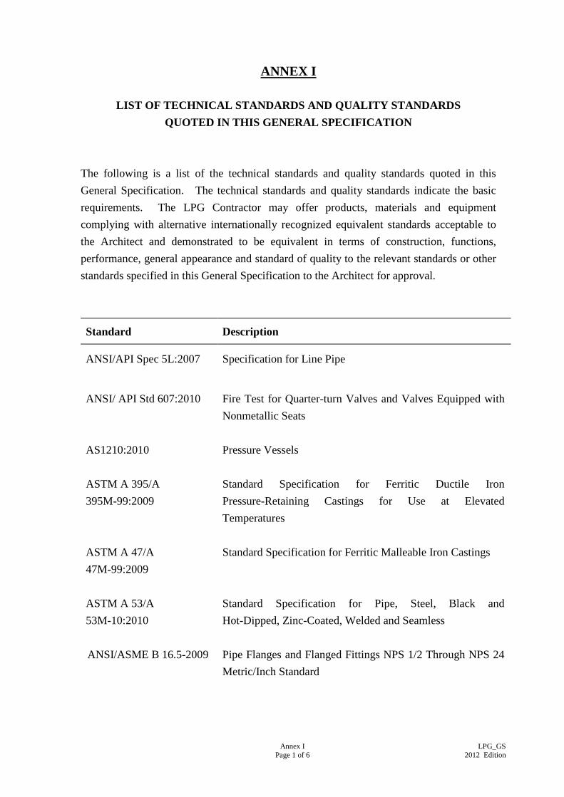
Annex I
Page 1 of 6
LPG_GS
2012 Edition
ANNEX I
LIST OF TECHNICAL STANDARDS AND QUALITY STANDARDS
QUOTED IN THIS GENERAL SPECIFICATION
The following is a list of the technical standards and quality standards quoted in this
General Specification. The technical standards and quality standards indicate the basic
requirements. The LPG Contractor may offer products, materials and equipment
complying with alternative internationally recognized equivalent standards acceptable to
the Architect and demonstrated to be equivalent in terms of construction, functions,
performance, general appearance and standard of quality to the relevant standards or other
standards specified in this General Specification to the Architect for approval.
Standard Description
ANSI/API Spec 5L:2007 Specification for Line Pipe
ANSI/ API Std 607:2010 Fire Test for Quarter-turn Valves and Valves Equipped with
Nonmetallic Seats
AS1210:2010 Pressure Vessels
ASTM A 395/A
395M-99:2009
Standard Specification for Ferritic Ductile Iron
Pressure-Retaining Castings for Use at Elevated
Temperatures
ASTM A 47/A
47M-99:2009
Standard Specification for Ferritic Malleable Iron Castings
ASTM A 53/A
53M-10:2010
Standard Specification for Pipe, Steel, Black and
Hot-Dipped, Zinc-Coated, Welded and Seamless
ANSI/ASME B 16.5-2009 Pipe Flanges and Flanged Fittings NPS 1/2 Through NPS 24
Metric/Inch Standard
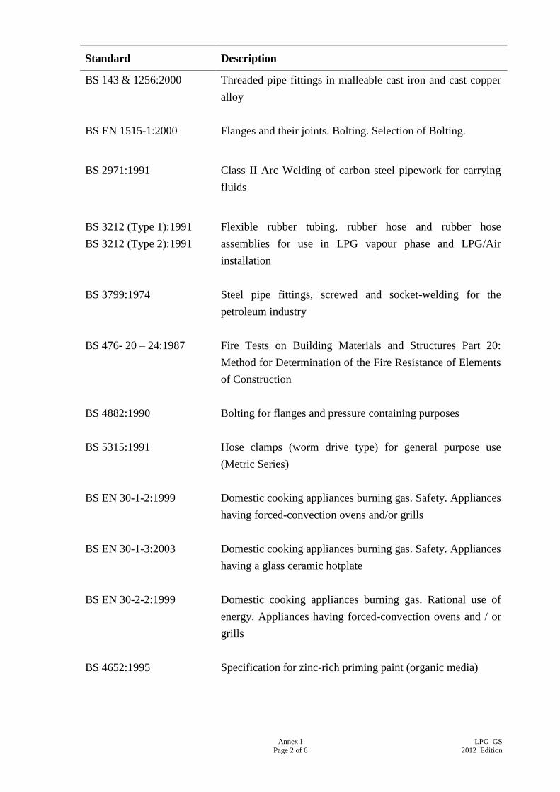
Annex I
Page 2 of 6
LPG_GS
2012 Edition
Standard Description
BS 143 & 1256:2000 Threaded pipe fittings in malleable cast iron and cast copper
alloy
BS EN 1515-1:2000
Flanges and their joints. Bolting. Selection of Bolting.
BS 2971:1991 Class II Arc Welding of carbon steel pipework for carrying
fluids
BS 3212 (Type 1):1991
BS 3212 (Type 2):1991
Flexible rubber tubing, rubber hose and rubber hose
assemblies for use in LPG vapour phase and LPG/Air
installation
BS 3799:1974 Steel pipe fittings, screwed and socket-welding for the
petroleum industry
BS 476- 20 – 24:1987 Fire Tests on Building Materials and Structures Part 20:
Method for Determination of the Fire Resistance of Elements
of Construction
BS 4882:1990 Bolting for flanges and pressure containing purposes
BS 5315:1991 Hose clamps (worm drive type) for general purpose use
(Metric Series)
BS EN 30-1-2:1999
BS EN 30-1-3:2003
BS EN 30-2-2:1999
BS 4652:1995
Domestic cooking appliances burning gas. Safety. Appliances
having forced-convection ovens and/or grills
Domestic cooking appliances burning gas. Safety. Appliances
having a glass ceramic hotplate
Domestic cooking appliances burning gas. Rational use of
energy. Appliances having forced-convection ovens and / or
grills
Specification for zinc-rich priming paint (organic media)
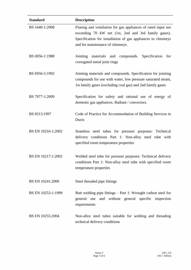
Annex I
Page 3 of 6
LPG_GS
2012 Edition
Standard Description
BS 5440-1:2008
Flueing and ventilation for gas appliances of rated input not
exceeding 70 kW net (1st, 2nd and 3rd family gases).
Specification for installation of gas appliances to chimneys
and for maintenance of chimneys.
BS 6956-1:1988 Jointing materials and compounds. Specification for
corrugated metal joint rings
BS 6956-5:1992 Jointing materials and compounds. Specification for jointing
compounds for use with water, low pressure saturated steam,
1st family gases (excluding coal gas) and 2nd family gases
BS 7977-1:2009 Specification for safety and rational use of energy of
domestic gas appliances. Radiant / convectors.
BS 8313:1997 Code of Practice for Accommodation of Building Services in
Ducts
BS EN 10216-1:2002 Seamless steel tubes for pressure purposes: Technical
delivery conditions Part 1: Non-alloy steel tube with
specified room temperature properties
BS EN 10217-1:2002 Welded steel tube for pressure purposes: Technical delivery
conditions Part 1: Non-alloy steel tube with specified room
temperature properties
BS EN 10241:2000 Steel threaded pipe fittings
BS EN 10253-1:1999 Butt welding pipe fittings – Part 1: Wrought carbon steel for
general use and without general specific inspection
requirements
BS EN 10255:2004 Non-alloy steel tubes suitable for welding and threading
technical delivery conditions
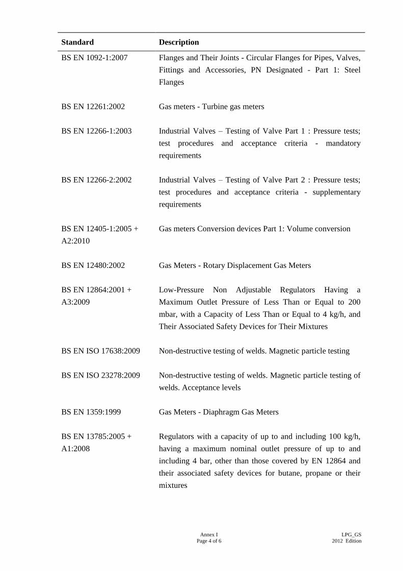
Annex I
Page 4 of 6
LPG_GS
2012 Edition
Standard Description
BS EN 1092-1:2007 Flanges and Their Joints - Circular Flanges for Pipes, Valves,
Fittings and Accessories, PN Designated - Part 1: Steel
Flanges
BS EN 12261:2002 Gas meters - Turbine gas meters
BS EN 12266-1:2003 Industrial Valves – Testing of Valve Part 1 : Pressure tests;
test procedures and acceptance criteria - mandatory
requirements
BS EN 12266-2:2002 Industrial Valves – Testing of Valve Part 2 : Pressure tests;
test procedures and acceptance criteria - supplementary
requirements
BS EN 12405-1:2005 +
A2:2010
Gas meters Conversion devices Part 1: Volume conversion
BS EN 12480:2002 Gas Meters - Rotary Displacement Gas Meters
BS EN 12864:2001 +
A3:2009
Low-Pressure Non Adjustable Regulators Having a
Maximum Outlet Pressure of Less Than or Equal to 200
mbar, with a Capacity of Less Than or Equal to 4 kg/h, and
Their Associated Safety Devices for Their Mixtures
BS EN ISO 17638:2009
Non-destructive testing of welds. Magnetic particle testing
BS EN ISO 23278:2009 Non-destructive testing of welds. Magnetic particle testing of
welds. Acceptance levels
BS EN 1359:1999 Gas Meters - Diaphragm Gas Meters
BS EN 13785:2005 +
A1:2008
Regulators with a capacity of up to and including 100 kg/h,
having a maximum nominal outlet pressure of up to and
including 4 bar, other than those covered by EN 12864 and
their associated safety devices for butane, propane or their
mixtures
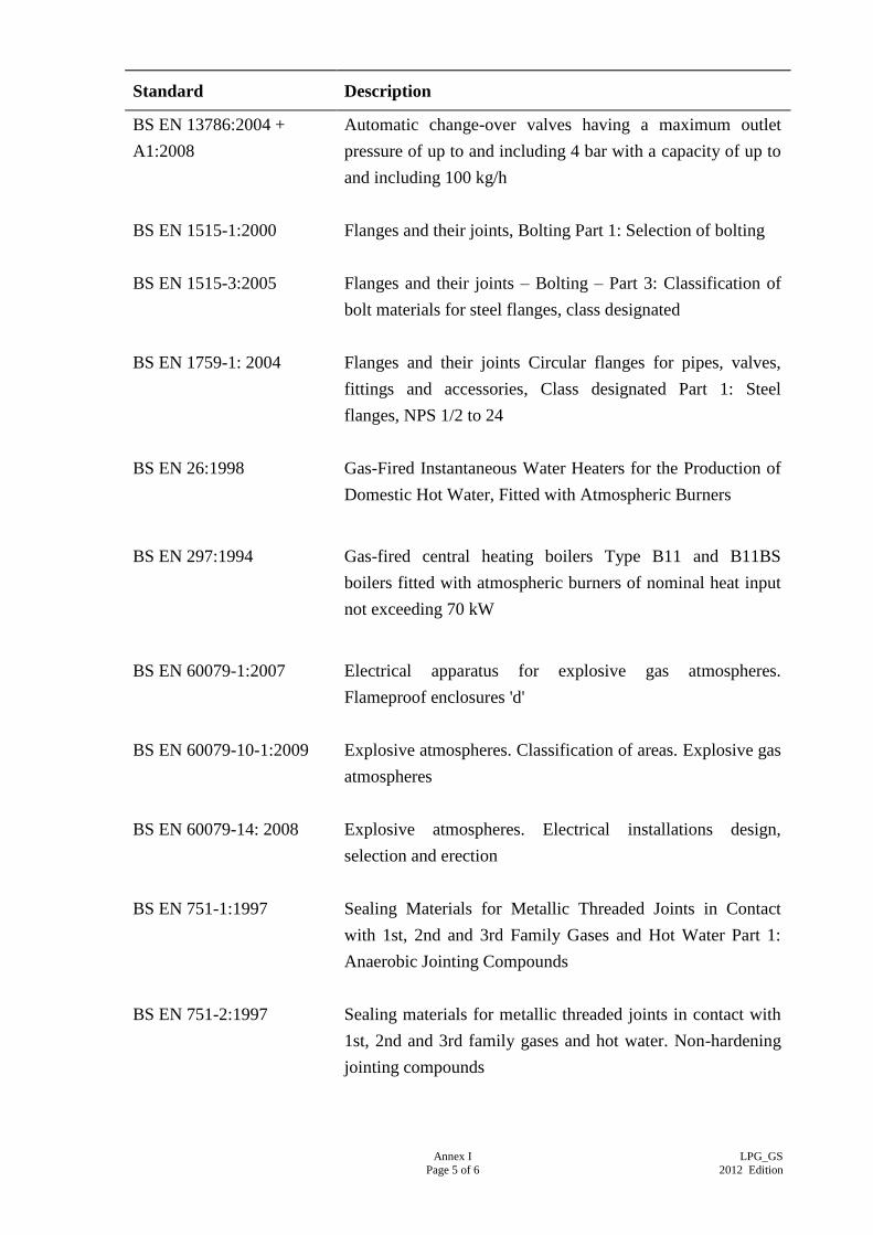
Annex I
Page 5 of 6
LPG_GS
2012 Edition
Standard Description
BS EN 13786:2004 +
A1:2008
Automatic change-over valves having a maximum outlet
pressure of up to and including 4 bar with a capacity of up to
and including 100 kg/h
BS EN 1515-1:2000 Flanges and their joints, Bolting Part 1: Selection of bolting
BS EN 1515-3:2005 Flanges and their joints – Bolting – Part 3: Classification of
bolt materials for steel flanges, class designated
BS EN 1759-1: 2004 Flanges and their joints Circular flanges for pipes, valves,
fittings and accessories, Class designated Part 1: Steel
flanges, NPS 1/2 to 24
BS EN 26:1998 Gas-Fired Instantaneous Water Heaters for the Production of
Domestic Hot Water, Fitted with Atmospheric Burners
BS EN 297:1994 Gas-fired central heating boilers Type B11 and B11BS
boilers fitted with atmospheric burners of nominal heat input
not exceeding 70 kW
BS EN 60079-1:2007 Electrical apparatus for explosive gas atmospheres.
Flameproof enclosures 'd'
BS EN 60079-10-1:2009 Explosive atmospheres. Classification of areas. Explosive gas
atmospheres
BS EN 60079-14: 2008 Explosive atmospheres. Electrical installations design,
selection and erection
BS EN 751-1:1997 Sealing Materials for Metallic Threaded Joints in Contact
with 1st, 2nd and 3rd Family Gases and Hot Water Part 1:
Anaerobic Jointing Compounds
BS EN 751-2:1997
Sealing materials for metallic threaded joints in contact with
1st, 2nd and 3rd family gases and hot water. Non-hardening
jointing compounds
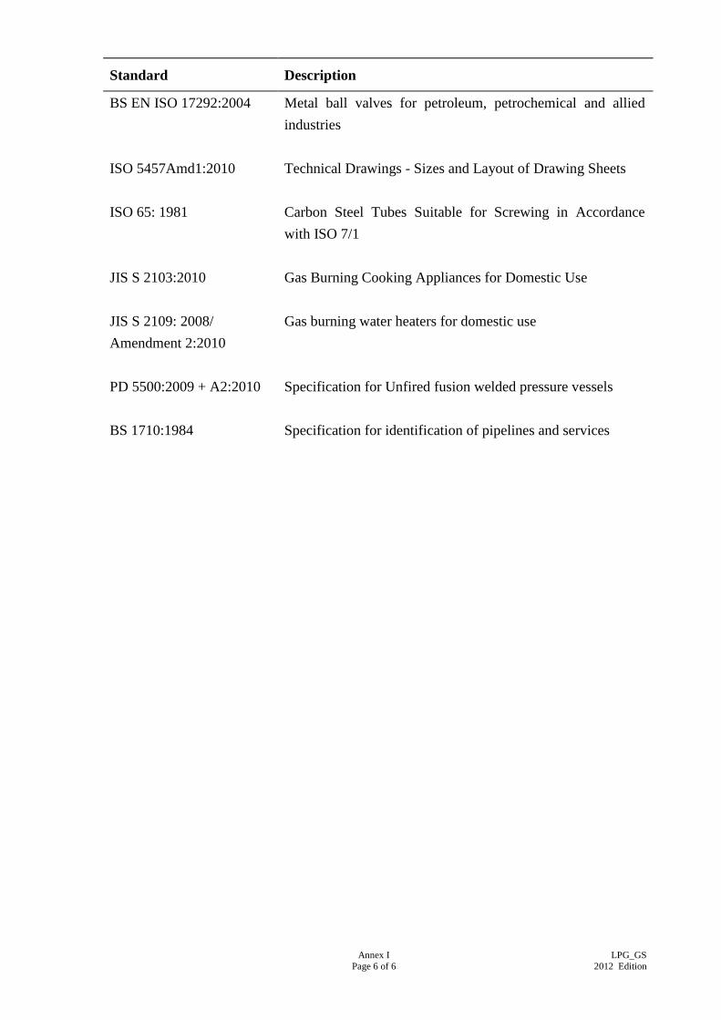
Annex I
Page 6 of 6
LPG_GS
2012 Edition
Standard Description
BS EN ISO 17292:2004
Metal ball valves for petroleum, petrochemical and allied
industries
ISO 5457Amd1:2010 Technical Drawings - Sizes and Layout of Drawing Sheets
ISO 65: 1981
Carbon Steel Tubes Suitable for Screwing in Accordance
with ISO 7/1
JIS S 2103:2010
Gas Burning Cooking Appliances for Domestic Use
JIS S 2109: 2008/
Amendment 2:2010
Gas burning water heaters for domestic use
PD 5500:2009 + A2:2010 Specification for Unfired fusion welded pressure vessels
BS 1710:1984
Specification for identification of pipelines and services