Lipińska, Marta and Olejnik, Lech and Pietras, Adam and ...
21
Elsevier Editorial System(tm) for Materials and Design Manuscript Draft Manuscript Number: JMAD-D-15-01798R3 Title: Microstructure and mechanical properties of friction stir welded joints made from ultrafine grained aluminium 1050 Article Type: Research Paper Keywords: Aluminium, Incremental Equal Channel Angular Pressing, Friction stir welding, Microstructure, Mechanical properties Corresponding Author: Mrs. Marta Lipinska, M.Sc. Corresponding Author's Institution: Warsaw University of Technology First Author: Marta Lipinska, M.Sc. Order of Authors: Marta Lipinska, M.Sc.; Lech Olejnik; Adam Pietras; Andrzej Rosochowski; Piotr Bazarnik; Jacek Goliński; Tomasz Brynk; Małgorzata Lewandowska Abstract: In order to obtain ultrafine grained structure, commercially pure aluminium (Al 1050) plates were subjected up to 8 passes of Incremental Equal Channel Angular Pressing (IECAP) following route C. Plates in different stages of IECAP were joined using Friction Stir Welding (FSW). All welded samples were investigated to determine their mechanical properties and structure evolution in the joint zone. The joining process reduced mechanical strength of material in the nugget zone, which was explained by the grain growth resulting from temperature rise during FSW. Nevertheless, the obtained results are promising in comparison to other methods of joining aluminium.
Transcript of Lipińska, Marta and Olejnik, Lech and Pietras, Adam and ...

Elsevier Editorial System(tm) for Materials and Design Manuscript Draft Manuscript Number: JMAD-D-15-01798R3 Title: Microstructure and mechanical properties of friction stir welded joints made from ultrafine grained aluminium 1050 Article Type: Research Paper Keywords: Aluminium, Incremental Equal Channel Angular Pressing, Friction stir welding, Microstructure, Mechanical properties Corresponding Author: Mrs. Marta Lipinska, M.Sc. Corresponding Author's Institution: Warsaw University of Technology First Author: Marta Lipinska, M.Sc. Order of Authors: Marta Lipinska, M.Sc.; Lech Olejnik; Adam Pietras; Andrzej Rosochowski; Piotr Bazarnik; Jacek Goliński; Tomasz Brynk; Małgorzata Lewandowska Abstract: In order to obtain ultrafine grained structure, commercially pure aluminium (Al 1050) plates were subjected up to 8 passes of Incremental Equal Channel Angular Pressing (IECAP) following route C. Plates in different stages of IECAP were joined using Friction Stir Welding (FSW). All welded samples were investigated to determine their mechanical properties and structure evolution in the joint zone. The joining process reduced mechanical strength of material in the nugget zone, which was explained by the grain growth resulting from temperature rise during FSW. Nevertheless, the obtained results are promising in comparison to other methods of joining aluminium.

Warsaw, 24 August 2015 Dear Editor, We are pleased to submit the revised version of the manuscript Ref. No. JMAD-D-15-01798R2 entitled „Microstructure and mechanical properties of friction stir welded joints made from ultrafine grained aluminium 1050” by M. Lipinska, L. Olejnik, A. Pietras, A. Rosochowski, P. Bazarnik, J. Golinski, T. Brynk and M. Lewandowska, which has been corrected according to the editorial comments. We have found the review instructive and it helped us to improve quality of the text to the level, which might hopefully meet the standards of your prestigious journal. Below you can find the answers to editorial comments. (1) Flow chart is not allowed in the graphic abstract. It has to be a single figure with no caption or title. Explanatory words have to be embedded into the figure. Answer: Graphic abstract has been changed in accordance with editorial recommendation. (2) Broken sentences are generally discouraged in the highlight. i.e. Plates were joined using friction stir welding -> so what? what is author's conclusion and novelty of that? Differences in the microstructure and mechanical properties of welds were observed -> then what are the differences?!? Answer: The highlights have been rewritten. Broken sentences are no longer present. I sincerely apologize for such mistakes. Sincerely yours, Marta Lipinska on behalf of all the authors
Detailed Response to Reviewers

*Graphical Abstract

Highlights
Ultrafine grained Al 1050 plates with enhanced mechanical properties were produced using
incremental ECAP, route C.
The plates were successfully joined using friction stir welding and good quality joints were
obtained.
The welding process caused grain growth in stir zone, however, the mechanical strength of
welds is higher than that of annealed Al 1050.
*Highlights (for review)

Microstructure and mechanical properties of friction stir welded
joints made from ultrafine grained aluminium 1050
Marta Lipińska
1*, Lech Olejnik
2, Adam Pietras
3, Andrzej Rosochowski
4, Piotr Bazarnik
1, Jacek Goliński
2,
Tomasz Brynk1 and Małgorzata Lewandowska
1
1
Faculty of Materials Science and Engineering, Warsaw University of Technology, Woloska 141, 02
507 Warsaw, Poland 2 Institute of Manufacturing Processes, Warsaw University of Technology, Narbutta 85, 02-524
Warsaw, Poland 3
Department of Friction and Resistance Welding and Environmental Engineering, Institute of
Welding, Czeslawa 16/18, 44-100 Gliwice, Poland 4 Design, Manufacture and Engineering Management, University of Strathclyde, 75 Montrose Street,
Glasgow G1 1XJ, United Kingdom
Corresponding author. Tel.: +48 222348740, e-mail address: [email protected]
Highlights
• Ultrafine grained Al 1050 plates with enhanced mechanical properties were produced using
incremental ECAP, route C.
• The plates were successfully joined using friction stir welding and good quality joints were
obtained.
• The welding process caused grain growth in stir zone, however, the mechanical strength of
welds is higher than that of annealed Al 1050.
Abstract
In order to obtain ultrafine grained structure, commercially pure aluminium (Al 1050) plates
were subjected up to 8 passes of Incremental Equal Channel Angular Pressing (IECAP) following route
C. Plates in different stages of IECAP were joined using Friction Stir Welding (FSW). All welded
samples were investigated to determine their mechanical properties and structure evolution in the
joint zone. The joining process reduced mechanical strength of material in the nugget zone, which
was explained by the grain growth resulting from temperature rise during FSW. Nevertheless, the
obtained results are promising in comparison to other methods of joining aluminium.
Keywords
Incremental Equal Channel Angular Pressing, Friction stir welding, Aluminium, Microstructure,
Mechanical properties
1. Introduction
Nowadays, materials with ultrafine grained (UFG) structure are becoming more and more
attractive for many industrial applications. The major advantage of these materials is their enhanced
mechanical strength at ambient temperature due to increased amount of grain boundaries acting as
obstacles for moving dislocations [1]. At elevated temperatures, the creep resistance decreases as
documented for pure aluminium [2,3]. However, creep resistance is strongly influenced by the
*ManuscriptClick here to view linked References

character of grain boundaries, i.e. creep ability increases for higher amount of high angle grain
boundaries. The creep resistance can be even improved for the grain structure containing the
majority of low-angle grain boundaries.
The extraordinary mechanical strength of UFG metals stimulated the development of their
production methods. Today, UFG metals can be efficiently produced by different variants of the
severe plastic deformation (SPD) method. However, the major restriction in wide industrial
application of UFG metals is the lack of a reliable welding process, which unlike riveting would give
material continuity in the joint. There is also a requirement to weld UFG materials without losing
their properties governed by the nanoscale structure. In this context, traditional welding processes
based on melting, such as brazing or arc welding, are not applicable because they occur at high
temperature causing a total change of structure leading to structure discontinuity and considerable
decrease in mechanical strength along the joining line. In this work, Friction Stir Welding (FSW) [4]
was chosen as an innovative bonding technology to weld aluminium. FSW takes place in the solid
state without reaching the melting temperature of the base material [5]. Stable connection is
obtained by mixing the friction-heated, plasticized and deformed metal along the contact line of
welded elements. It can be performed by moving a rotating tool (a pin with a shoulder) along a
joining line. The key factor for obtaining a consistent joint is large plastic deformation at elevated
temperature. It results in bringing-up atoms to a distance which allows creation of a metallic bond.
Accompanied by increased density of lattice defects, the final microstructure in different joint areas
is mainly dependent on dynamic recrystallization and/or recovery [6] what is common for materials
such as aluminium, which is characterized by high stacking fault energy.
Compared to other joining techniques, FSW exhibits a number of advantages. The rise in
temperature cannot be higher than a melting point. On account of that, problems related with
resolidification, such as porosity, embrittlement and formation of second phase are not present.
Additionally, distortion and residual stresses, which are seen in FSW joints, are lower than those
observed for other methods, based on melting of the base material and a filler [5]. Parameters of the
FSW process are crucial for quality and properties of obtained joints. For example, many papers were
devoted to shoulder diameter [7,8], which appears to be one of the most influential factors. Other
parameters such as pin profile [9,10], tool travel and rotation speeds [11,12], depth of pin's
penetration were investigated too. Structural features, e.g. initial grain size, were also taken into
consideration [13,14].
Joining UFG aluminium and its alloys was also a subject of numerous investigations. Plates with
refined structure, obtained during accumulated roll bonding (ARB) [14] or constrained groove
pressing (CGP) [15,16] were joined using FSW. In each case, authors attempted maximizing
mechanical properties and preventing grain growth in the joint zone. Relying on the improved
properties in coarse grained materials, materials with refined structure were taken into similar
investigation. When the initial material is annealed and characterized by coarse grained structure,
subsequent FSW leads to the creation of new, equiaxial grains with much smaller size than the initial
one. As a result the improvement in mechanical properties is observed [13]. In the case of materials
with already refined structure, the FSW process leads to grain growth in the joint zone, which seems
to be extremely difficult to overcome. As was shown for aluminium 1050 [16], which is the same
material as in this study, annealed samples subjected to FSW exhibited a very fine grain structure in
the joint, which was formed by dynamic recrystallization. In the same investigation, materials with
the initial refined structure revealed an intense reduction of microhardness in the stir zone, which
was explained by the grain growth. It was caused by thermal instability resulting from high stored

energy during severe plastic deformation. The samples after ARB were also annealed [13], which
enabled achieving the best compromise between grain size and hardness. Unfortunately, joining
immediately after ARB caused a decrease in mechanical properties of the stir zone. The conclusion
from this work was that regardless of the initial grain size or shape, samples revealed equiaxial grains
in the stir zone. Nevertheless, for base materials with UFG structure, there was a grain growth
observed in the joints.
The aim of the present work was to join technically pure aluminium plates with ultrafine
grained structure produced by Incremental Equal Channel Angular Pressing (IECAP) using FSW
process and then determine the relationship between microstructure and mechanical properties in
the base materials and joints.
2. Material and methods
The investigated material was technically pure aluminium (99,5 wt%) EN AW-1050A-H24
supplied by the Konin Aluminium plant in the form of 3 mm thick rolled sheets. The exact chemical
composition is presented in Table 1.
Table 1. Chemical composition of aluminium 1050
Si Fe Cu Mn Mg Zn Al
Content [%] 0.25 0.40 0.05 0.05 0.05 0.07 balance
The samples with dimensions of 3x62x105 mm were processed using IECAP [17] to obtain UFG
structure. The main idea of this method is to apply plastic strain in a series of small deformation
increments [18], which are based on simple shear. Separation of feeding and deformation steps
reduces friction during feeding, which enables processing of very long or continuous billets. As
conventional ECAP, this method has the ability to pass the ingot via different routes. With square
plates, there is a possibility of employing deformation route based on rotation about the normal to
the plate (Z axis), which in the case of aluminium led to a homogenous UFG structure [19] with a
large number of high angle boundaries [20]. In this study the applied deformation route was based
on the rotation of plates about their longitudinal axis by 180˚ between passes (so called route C). The
plates were investigated in an initial state (0 passes), after 4 and 8 passes of IECAP, which
corresponds to true strains of 0, 4.6 and 9.2, respectively. To simplify the sample description, they
were described as sample ‘0’, ‘4’ and ‘8’ , depending on the number of applied passes.
The plates of the same type (i.e. subjected to the same processing path) were joined together
using FSW, with the tool shoulder diameter of 17 mm and pin diameter of 5.5 mm. Samples were
butt welded along Y plane, which means that joints were made along a longer edge of the
rectangular plate. Rotational and linear speeds (Table 2) were different for materials with different
number of IECAP passes, which comes from their structural differences.
Table 2. Values of rotational and linear speed used in FSW process
Sample Rotational speed
n [rpm]
Linear speed
Vz [mm/min]
0 450 224
4 560 355
8 560 224

To reveal the microstructure of the joints, different techniques were implemented. Anodized
metallographic specimens were observed in a light microscope using a polarized light beam. For
detailed microstructure investigations, Focused Ion Beam (FIB) and Transmission Electron
Microscope (TEM) JEOL JEM 1200 with accelerating voltage of 120 kV were used. Samples for FIB and
TEM observations were cut out in the X plane, which is perpendicular to the welding line and also
perpendicular to IECAP direction. Thin foils were prepared using a wire saw, ground down to 150 µm
and electropolished using Struers Tenupol-5 system operating at a voltage of 35 V at a temperature
of 278K. The solution containing ethanol, perchloric acid, butyl glycol and distilled water was used.
Microstructure observations were taken together with the Selected Area Electron Diffraction (SAED)
patterns with an aperture of effective diameter about 4 µm. Grain size was determined by calculating
the equivalent diameter (d2), which means the diameter of a circle with equal area as the
investigated grain [21].
In order to characterize mechanical properties, tensile tests and microhardness measurements
were carried out. In the case of tensile test, flat mini samples with a thickness of 0.6 mm (Fig. 1) were
used. Tensile samples were perpendicular to the direction of the welding line marked also as the
joining direction. Digital Image Correlation (DIC) has been used for accurate strain determination. Stir
zone and base material were investigated separately in order to reveal differences between these
two areas. For each zone 5 specimens were investigated. Microhardness measurements were carried
out in the X plane of samples under a load of 200 g for 15 s. For each sample, 120 measurements
were done in 3 parallel lines with 1 mm spacing along width and 0.5 mm along thickness of the butt
welded rectangular plate.
Fig. 1. Schematic illustration of tensile specimens together with their locations in butt welded plate
(JD – joining direction along length of the plate)
3. Results
3.1. Microstructure
Microstructures of base materials together with histograms of grain size distribution are
presented in Fig. 2. Sample ‘0’ (in initial state) features a typical cold rolled structure with elongated
grains of several microns in length. The average grain/subgrain size was about 2 µm. IECAP brought
about significant microstructure refinement. After 4 passes, the grain size was reduced to about 655
nm. Further processing (up to 8 passes) only slightly affected the grain size which average value
decreased to 630 nm. Histograms look comparable which is an evidence for similar structure of these
two materials. The quantitative data regarding the microstructures is summarized in Table 3. Apart
from equivalent diameter (d2) and standard deviation (S.D.), grain elongation factor (dmax/d2) and
grain boundary development factor (p/d2∙), where p is perimeter) were determined. The sample ‘0’

exhibits the highest value of grain elongation factor which is a clear evidence for elongated grains.
With increasing number of IECAP passes, the grains become more equiaxial, which is reflected in
lower value of this factor. Grain boundary development factor is slightly higher for the sample ‘0’
when compared to the samples ‘4’ and ‘8’, which is due to higher elongation of the grains.
Table 3. Quantitative parameters describing the microstructure in base materials (BM) and the
nuggets (N): d2 – average grain diameter, S.D. – standard deviation, dmax/d2 – grain elongation factor,
p/d2∙ – grain boundary development factor (p – grain perimeter)
d2 [µm] S.D. [µm] dmax/d2 p/d2∙
0 BM 1.91 1.10 1.89 14.20
4 BM 0.655 0.23 1.63 12.92
8 BM 0.630 0.28 1.45 13.07
0 N 4.30 1.49 1.34 11.67
4 N 4.35 1.93 1.36 12.07
8 N 4.56 2.17 1.36 11.95

Fig. 2. Representative microstructures of base materials: (a) initial state, (b) after 4 and (c) after 8
passes of IECAP (X plane perpendicular to welding line) together with histograms of grain sizes (d2)
The images of weld zones for welds are shown in Fig. 3. In each case the picture was taken
from both the advancing side (AS) and retreating side (RS) of the weld. These two zones differ in the
relative directions of deformation induced by tool rotation and tool advancement. They are parallel
but in advancing side they proceed in the same direction while in retreating side in opposite
directions. As a consequence, the deformation degree is higher on advancing side. On the images,
one can distinguish heat affected zone (HAZ), termomechanically affected zone (TMAZ), which is a
transition zone, and nugget zone (NZ), which is characterized by complete recrystallization. The
region outside the weld zone, which is unaffected by heat or deformation is the parent material,
called here base material (BM). TMAZ is the most distinct in ‘0’ joint. Also the width of this zone in
this joint is the biggest. In ‘8’ joint, TMAZ is very gentle. The transition between HAZ and stir zone is
very smooth. On the other hand, in ‘8’ joint the difference in grain colors is the biggest. It indicates
the highest differences in grain orientation. BM in initial state reveals very strong morphological
texture due to rolling process. As can be seen in Fig. 3, the greater degree of deformation, the
structure in base material becomes more equiaxial.
a) AS RS

Fig. 3. Weld zones for samples: (a) ‘0’, (b) ‘4’ and (c) ‘8’
Fig. 4 shows the microstructures of the nuggets for ‘0’, ‘4’ and ‘8’ samples together with the
histograms of grain size distribution. Generally, the joint zone exhibits greater grain size than the
base material in each case. For all samples, the structure in the nugget is very similar and consists of
equiaxial grains with the similar average size of about 4 µm (Table 3), regardless of base material
structure, which is consistent with the results reported in [14]. The histograms reveal that the most
homogenous grain size distribution in the nugget was obtained for ‘0’ sample (0n). Nuggets of ‘4’ and
‘8’ samples exhibit a greater scatter of grain size, which is reflected in more flat histograms. The grain
elongation factor (dmax/d2) for nuggets is at the same level. Its value (≈1.36) is typical for equiaxial
grains (see data in Table 3). Grain boundary development factor also shows comparable values.
c) AS RS
b) AS RS
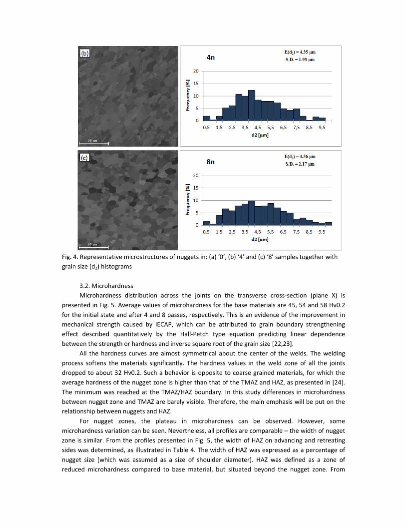
Fig. 4. Representative microstructures of nuggets in: (a) ‘0’, (b) ‘4’ and (c) ‘8’ samples together with
grain size (d2) histograms
3.2. Microhardness
Microhardness distribution across the joints on the transverse cross-section (plane X) is
presented in Fig. 5. Average values of microhardness for the base materials are 45, 54 and 58 Hv0.2
for the initial state and after 4 and 8 passes, respectively. This is an evidence of the improvement in
mechanical strength caused by IECAP, which can be attributed to grain boundary strengthening
effect described quantitatively by the Hall-Petch type equation predicting linear dependence
between the strength or hardness and inverse square root of the grain size [22,23].
All the hardness curves are almost symmetrical about the center of the welds. The welding
process softens the materials significantly. The hardness values in the weld zone of all the joints
dropped to about 32 Hv0.2. Such a behavior is opposite to coarse grained materials, for which the
average hardness of the nugget zone is higher than that of the TMAZ and HAZ, as presented in [24].
The minimum was reached at the TMAZ/HAZ boundary. In this study differences in microhardness
between nugget zone and TMAZ are barely visible. Therefore, the main emphasis will be put on the
relationship between nuggets and HAZ.
For nugget zones, the plateau in microhardness can be observed. However, some
microhardness variation can be seen. Nevertheless, all profiles are comparable – the width of nugget
zone is similar. From the profiles presented in Fig. 5, the width of HAZ on advancing and retreating
sides was determined, as illustrated in Table 4. The width of HAZ was expressed as a percentage of
nugget size (which was assumed as a size of shoulder diameter). HAZ was defined as a zone of
reduced microhardness compared to base material, but situated beyond the nugget zone. From

these results, one can observe some general trends. The width of retreating side is greater than the
advancing side width in all specimens. Furthermore, with increasing plastic deformation of the base
material, HAZ also increases, regardless of the weld side.
Fig. 5. Microhardness profiles for (a) ‘0’ joint, (b) ‘4’ joint, (c) ‘8’ joint
AS RS
HAZ NZ HAZ
TMAZ TMAZ
AS RS
HAZ NZ HAZ
TMAZ TMAZ
AS RS
HAZ NZ HAZ
TMAZ TMAZ
a)
b)
c)

Table 4. The width of HAZ on AS and RS as a percentage of nugget width
‘0’ ‘4’ ‘8’
Advancing side 20% 44% 53%
Retreating side 32% 56% 62%
3.3. Tensile properties
The representative tensile stress-strain curves for micro-specimens cut out from base
materials and the nuggets are presented in Fig. 6. Additionally, a curve for the annealed Al 1050 is
shown for comparative purposes. In general, the strength of base materials determined as ultimate
tensile strength (UTS) and yield strength (YS) is significantly higher than that of nuggets. Values of
UTS, YS, elongation to break (A) and uniform elongation (Ag) are summarized in Table 5, as an
average value from 5 measurements. It should be noted that the values of YS and UTS for IECAP
processed samples (base materials) are very similar (no significant work hardening is observed during
tensile test), which implies that UTS and YS can even overlap when the standard deviation is
considered. Rapid necking is typical for ultrafine grained materials processed by severe plastic
deformation [25,26] and further promoted by the small dimensions of tensile samples used in the
present study. The variation in tensile properties of the samples of the same type may be due to the
incomplete homogeneity of the tested materials, resulting from the not fully refined structures in
materials after plastic deformation. YS for base materials varies from 130 to 176 MPa for sample ‘0’
and ‘8’, respectively. It should be noted that such values of YS are typical for pure aluminium in work
hardened and/or ultrafine grained state. The flow stress quickly achieves a maximum value and then
decreases gradually, which indicates that necking occurs early and further deformation is
accompanied by a deepening neck. As a consequence, the elongation to failure is limited and below
10% for UFG samples. Additionally uniform elongation for these materials is very low and does not
exceed 1%. The tensile curves for samples cut from nuggets are different. The values of YS and UTS
are significantly lower – below 100 MPa. However, joint ‘8’ exhibits higher YS than the other joints. In
addition, the nugget samples have considerable higher values of elongation (26-36%). It should also
be noted that the nuggets of SPD processed samples exhibit better combination of strength and
ductility, i.e. higher YS and UTS, as well as higher elongation. The curve for annealed sample, marked
in red, reveals the lowest values of YS and UTS among all materials. Elongation value is comparable
to the results achieved for 4N and 8N. Obtained results are entirely consistent with the
aforementioned Hall-Petch’s equation for the relationship between grain size and yield stress.

Fig. 6. Stress-strain curves for tensile specimens cut from base material (BM - solid lines) and nugget
(N- dashed lines) for 0, 4 and 8 IECAP passes; red line – annealed material
Table 5. Values of Ultimate Tensile Strength (UTS), Yield Strength (YS), elongation to break (A) and
uniform elongation (Ag) of base materials (BM) and nuggets (N) for all micro-specimens
Specimen UTS (MPa) YS (MPa) A (%) Ag (%)
0 BM 135 5 130 5 12.7 0.7 1.5 0.1
4 BM 180 8 172 4 9.7 1.2 0.8 0.2
8 BM 184 7 176 5 7.5 0.8 0.6 0.1
0 N 88 5 63 2 26.2 1.5 14.2 1.2
4 N 94 2 66 4 33.2 3.2 21.4 0.9
8 N 95 2 79 5 36.5 3.7 22.4 1.1
annealed 77 2 45 2 34.7 3.0 25.3 1.2
4. Discussion
4.1. Mechanism of grain refinement during IECAP processing
Microstructure observations gave a clear evidence of grain size refinement during IECAP
processing. However, to determine its mechanism more detailed investigations are needed. Careful
inspection using TEM (Fig. 7) revealed more details in the structure development. The sample ‘0’ (Fig.
7 (a)) exhibits a strong morphological texture and dislocation substructure within the grains. Samples
after IECAP feature refined grain structure. Inside the grains, one can see free dislocations. The
sample after 4 passes exhibits the inhomogeneous structure, which contains both – elongated and
equiaxial grains, as shown in Fig. 7 (b). Further deformation did not cause successive reduction of the
thickness of elongated grains but resulted in more equiaxial grains (Fig. 7 (c)). It indicates that grain
refinement in this stage proceeds through subdivision of elongated grains by transverse boundaries.
Such a microstructure evolution is typical for ECAP based processes. It is well established that for
small applied strains (usually up to 4 passes), the microstructure consists of elongated deformation
bands which at a closer look reveal to be transversely divided to create a dislocation cell structure

[27-30]. The width of the bands decreases with imposed strain until they reach the smallest possible
size. Further microstructure evolution relies on an increase in misorientation angles of grain and
subgrain boundaries [31,32] leading to a reasonably equiaxial grain structure with the majority of
high angle grain boundaries (usually at the level of 70%) [28].
In the context of microstructure evolution, one should also consider the role of sample
rotation between consecutive passes. From this point of view, four distinct processing routes have
been established: route A, in which the sample is not rotated between passes, route BA and BC where
the sample is rotated by 90o either in alternative directions or in the same direction and route C, in
which the sample is rotated by 180o. It was reported that the most efficient in terms of creation of
equiaxial grains is the route BC due to a large angular range of shearing planes [27]. However, the
highest efficiency in terms of high angle grain boundary formation was documented for the route A
due to the lack of redundant strain [29]. The route C investigated here is known to be the most
practical but the least efficient. This is why the microstructure is not fully equiaxial after 8 passes.
The same number of IECAP with rotation about Z axis (instead of X) led to the formation of fully
equiaxial microstructure with a very high fraction of high angle grain boundaries of about 80% [20],
which was attributed to the activation of different slip systems in consecutive passes (thanks to
sample rotation) and the lack of redundant strain which results in early establishment of equiaxial
grain structure.
However, the advantage of the route C in IECAP used here for grain size refinement is that
both surfaces of the plates are alternatively die and punch sides, which may lead to more
homogenous microstructure across the plate’s thickness. This phenomenon will be the subject of a
separate study.
a)

b)
c)
Fig. 7. Representative microstructures of Al 1050 together with SAED patterns: (a) initial state, (b) 4
passes and (c) 8 passes of IECAP (X plane perpendicular to welding line)
4.2. Factors influencing microstructural changes in weld zones
Microstructure observations (see section 3.1) gave a clear evidence of microstructural changes
within weld zones. They are caused by the heat generated by friction of the tool shoulder and
deformation induced by the tool pin during FSW. TMAZ is characterized by highly deformed and
elongated grains. As can be seen in Fig. 3, the interface between zones is different on the advancing
and the retreating side. TMAZ on the advancing side is well defined, which is an evidence of the
distinct difference in grain sizes between zones. The retreating side is more diffused. This
observation is in agreement with other works [9,33] and is explained by the differences in plastic
flow state on both sides of a weld during FSW. On AS, the directions of deformation and tool
translation are the same, which results in higher shear force and higher plastic strain imposed
compared to RS, where the plastic strain is smaller [24].
The grains in nuggets form as a result of dynamic recrystallization during plastic deformation
and heating caused by friction between the welding tool and the workpiece [34]. During FSW
process, the temperature rise is high enough to induce recrystallization. The peak temperature can

be in the range from 0.6 to even 0.95 Tmelt, and depends on the material, tool arrangement and
process conditions [35]. Also, the shoulder diameter plays an important role [8]., i.e. an increase in
shoulder diameter increases the peak weld temperature. The maximum predicted temperature is
located under the rim of the shoulder. For the shoulder diameter of 40 mm, temperature can rise up
to 400 ˚C, whereas in the case of 20 mm diameter (our study – 17 mm), the peak temperature
reached 200˚C, which was consistent with predictions.
The temperature rise is also influenced by the properties of joined materials. For high strength
materials, one may expect higher heat input. This is one of the reasons for different behavior of
coarse grained and deformed materials [13-16]. In former ones, stir zone (SZ) exhibits higher strength
and hardness whereas for the latter dynamic recrystallization and SZ softening is observed. In our
case, the base materials are all in the deformed state with relatively small grain size varying from 2 to
0.6 µm. They all undergo dynamic recrystallization during FSW, which is also promoted by the high
density of defects (mainly grain boundaries). Although the most pronounced grain growth has been
observed for sample ‘8’ (as illustrated in Table 3), the final microstructure in the nuggets is very
similar in all samples. The average grain size is only slightly higher for sample ‘8’ when compared to
sample ‘0’ (4.56 versus 4.30 µm). It is believed that the differences in the microstructure and the
properties of based materials are small enough to not influence the final microstructure in the
nuggets, which is mainly governed by welding parameters.
During welding, grain coarsening occurs not only in the nugget zone but also in adjacent areas
due to heat dissipation. The higher the plastic deformation imposed in the IECAP process, the wider
HAZ around the nugget. This may be attributed to different amount of heat generated for softer and
stronger materials. Although this difference does not cause changes in the nuggets of investigated
joints, it is sufficient to affect HAZ. In addition, samples ‘4’ and ‘8’ feature smaller grain size and are
more prone to grain growth. These two factors bring about different width of HAZ in samples
subjected to different IECAP processing.
Microhardness measurements also revealed differences between advancing and retreating
sides. For each sample, the HAZ is greater by about ten percentage points in retreating side. It means
that in advancing side the heat input is smaller. It has to be correlated with material flow and heat
generated during FSW, which leads to a larger area of the deformed grains on retreating side. This is
in agreement with the microstructural investigation, where transition zone in retreating side was
more diffused and smoother. Advancing side, on the other hand, was steeper.
4.3. Comparison to other joining techniques
Generally, FSW welding of aluminium plates after SPD causes a relatively high reduction in
hardness in the stir zone, which is consistent with results obtained in [13,16]. In this zone, grain
coarsening is expected to occur due to temperature rise during FSW. Contrary to previous reports
showing enhanced mechanical strength after FSW [8,13], the stir zone in ‘0’ sample exhibits lower
values of microhardness than the base material. However, it should be noted that ‘0’ sample in our
case was cold rolled and thus work hardened (H24 hardening state) whereas in the cited reports the
joined materials had coarse grained structure after annealing. The possibility of improving
mechanical properties of the joint zone is a significant advantage of the FSW method. However, in
the case of material with UFG structure, it is more challenging because of the unstable nature of the
UFG material and temperature rise during FSW.
However, it should be noted that although grain growth occurred in the welded zone of UFG
aluminium, the grain size (about 4 µm) is relatively small and resulting mechanical strength (YS=80
MPa) relatively high as for technically pure aluminium. It should be noted that annealed Al 1050
exhibits lower value of the yield strength (45 MPa) than the nugget samples, with similar elongation.
FSW process decreased enhanced mechanical strength resulting from IECAP processing, but the
strength in nuggets is still improved compared to commercially available annealed material.
The mechanical properties of the FSW joints are also higher than compared to other joining
techniques. For instance, a decrease in YS between an Al-Mg-Sc alloy base material and joint is 20%
in plates joined by FSW, and 50% between BM and TIG joint [36]. In case of Al 6xxx [37], yield
strength is slightly smaller for FSW joints than for MIG joints, but FSW specimens present higher
values of rupture stress and elongation. Also detailed hardness examination revealed lower values in
the MIG welded specimens. It can be thus concluded that FSW process is one of the most promising
methods of joining materials with UFG structure. Therefore, it is worth investigating solid bonding by
FSW using different UFG aluminium alloys.
5. Conclusions
Technically pure aluminium samples were subjected to severe plastic deformation by
Incremental ECAP and then joined by FSW. The following conclusions based on the present study can
be formulated.
1. The plates subjected to IECAP revealed the refined microstructure with average grain
size of about 600 nm and improved mechanical strength and microhardness.
2. The ultrafine grained structure obtained by severe plastic deformation is unstable
because of temperature rise during FSW.
3. Microstructure in the nugget zone for all joints consists of equiaxial grains with
average value of 4.30-4.56 microns.
4. For all materials significant reduction in the microhardness of stir zone had occurred.
5. Despite the deterioration of mechanical properties and grain growth in joints
compared to hardened base material, good quality butt joints were produced using
FSW for UFG aluminium plates.
6. FSW is one of the most attractive methods of joining UFG aluminium, especially in
comparison to other techniques such as TIG or MIG.
Acknowledgement
This work was financed by National Centre for Research and Development (Contract no.
WPN/6/2013).
References:
[1] Meyers MA, Mishra A, Benson DJ. Mechanical Properties of Nanostructured Materials, Progress in
Material Science 2006;51;427-556.
[2] Sklenicka V, Dvorak J, Svoboda M. Creep in ultrafine grained aluminium, Materials Science and
Engineering A 2004;387-389;696-701.
[3] Saxl I, Sklenicka V, Ilucova L, Svoboda M, Dvorak J, Kral P. The link between microstructure and
creep in aluminum processed by equal-channel angular pressing, Materials Science and Engineering
A 2009;503;82-85.
[4] Thomas WM, Nicholas ED, Needham JC, Murch MG, Templesmith P, Dawes CJ. Friction Stir
Welding 1991.

[5] Gibson BT, Lammlein DH, Prater TJ, Longhurst WR, Cox CD, Ballun MC, Dharmaraj KJ, Cook GE,
Strauss AM. Friction stir welding: Process, automation and control, Journal of Manufacturing
Processes 2014;16;56-73.
[6] McNelley TR, Swaminatham S, Su JQ. Recrystallization mechanisms during friction stir
welding/processing of aluminum alloys, Scripta Materialia 2008;58;349-354.
[7] Arora A, De A, DebRoy T. Toward optimum friction stir welding tool shoulder diameter, Scripta
Materialia 2011;64;9-12.
[8] Uygur I. Influence of shoulder diameter on mechanical response and microstructure of FSW
welded 1050 Al-alloy, Archives of Metallurgy and Materials 2012;57;53-60.
[9] Xu W, Liu J, Zhu H, Fu L. Influence of welding parameters and tool pin profile on microstructure
and mechanical properties along the thickness in a friction stir welded aluminum alloy, Materials and
Design 2013;47;599-606.
[10] Aval HJ. Influences of pin profile on the mechanical and microstructural behaviors in dissimilar
friction stir welded AA6082-AA7075 butt Joint, Materials and Design 2015;67;413-421.
[11] Movahedi M, Kokabi AH, Seyed Reihani SM, Najafi H. Mechanical and Microstructural
Characterization of Al-5083/St-12 lap joints made by friction stir welding, Procedia Engineering
2011;10;3297-3303.
[12] Movahedi M, Kokabi AH, Seyed Reihani SM, Najafi H. Effect of tool travel and rotation speeds on
weld zone defects and joint strength of aluminium steel lap joints made by friction stir welding,
Science and Technology of Welding and Joining 2012;17(2);162-167.
[13] Sun Y, Fujii H, Takada Y, Tsuji N, Nakata K, Nogi K. Effect of initial grain size on the joint
properties of friction stir welded aluminium, Materials Science and Engineering A 2009;527;317-321.
[14] Topic I, Hoppel HW, Goken M. Friction stir welding of accumulative roll-bonded commercial-
purity aluminium AA1050 and aluminium alloy AA6016, Materials Science and Engineering A
2009;503;163-166.
[15] Khorrami MS, Kazeminezhad M, Kokabi AH. Microstructure evolutions after friction stir welding
of severely deformed aluminum sheets, Materials and Design 2012;40;364-372.
[16] Khorrami MS, Kazeminezhad M, Kokabi AH. Mechanical properties of severely plastic deformed
aluminum sheets joined by friction stir welding, Materials Science and Engineering A 2012;543;243-
248.
[17] Olejnik L, Rosochowski A, Richert M. Incremental ECAP of plates, Materials Science Forum
2008;584-586;108-113.
[18] Rosochowski A, Olejnik L. FEM Simulation of Incremental Shear. American Institute of Physics,
Conf. Proceedings edited by E. Cueto and F. Chinesta Vol. 907, 2007, 653 -658.
[19] Olejnik L, Chrominski W, Rosochowski A, Lipinska M, Lewandowska M. Incremental ECAP as a
novel tool for producing ultrafine grained aluminium plates, 2014 IOP, Conf. Ser.: Mater. Sci. Eng. 63
012004 doi:10.1088/1757-899X/63/1/012004.
[20] Chrominski W, Olejnik L, Rosochowski A, Lewandowska M. Grain refinement in technically pure
aluminium plates using incremental ECAP processing, Materials Science and Engineering A 2015;636;
172-180.
[21] Wejrzanowski T, Pielaszek R, Opalińska A, Matysiak H, Łojkowski W, Kurzydłowski KJ.
Quantitative methods for nanopowders characterization, Applied Surface Science 2006;253;204-208.
[22] Hall EO. The deformation and ageing of mild steel: III. Discussion of results, Proceedings of the
Physical Society of London Sect B 1951;64(9)189-200.

[23] Sato YS, Kokawa H, Enomoto M, Ikeda K. Hall-Petch relationship in friction stir welds of equal
channel angular-pressed aluminum alloys, Materials Science and Engineering A 2004;354(1-2);298-
305.
[24] Zhang F, Xuekuan S, Chen Z, Nie Z. Effect of welding parameters on microstructure and
mechanical properties of friction stir welded joints of a super high strength Al-Zn-Mg-Cu aluminum
alloy, Materials and Design 2015;67;483-491.
[25] Kamachi M, Furukawa M, Horita Z, Langdon TG. Equal-channel angular pressing using plate
samples, Materials Science and Engineering A 2003;361;258-266.
[26] Horita Z, Fujinami T, Langdon TG. The potential for scaling ECAP: effect of sample size on grain
refinement and mechanical properties, Materials Science and Engineering A 2001;318(1-2);34-41.
[27] Iwahashi Y, Horita Z, Nemoto M, Langdon TG. The process of grain refinement in equal-channel
angular pressing, Acta Materialia 1998;46(9);3317-3331.
[28] Prangnell PB, Bowen JR, Apps PJ. Ultra-fine grain structures in aluminium alloys by severe
deformation processing, Materials Science and Engineering A 2004;375–377;178–185.
[29] Gholinia A, Prangnell PB, Markushev MV. The effect of strain path on the development of
deformation structures in severely deformed aluminium alloys processed by ECAE, Acta Materialia
2000;48;1115–1130.
[30] Cao WQ, Godfrey A, Liu Q. EBSP investigation of microstructure and texture evolution during
equal channel angular pressing of aluminium, Materials Science and Engineering A 2009;361;9–14.
[31] Cabibbo M, Blum W, Evangelista E, Kasser ME, Meyers MA. Transmission Electron Microscopy
Study of Strain-Induced Low- and High-Angle Boundary Development in Equal-Channel Angular-
Pressed Commercially Pure Aluminum, Metallurgical and Materials Transactions A 2008;39;181–189.
[32] Chowdhury SG, Mondal A, Gubicza J, Krallics G, Fodor A. Evolution of microstructure and texture
in an ultrafine-grained Al6082 alloy during severe plastic deformation, Materials Science and
Engineering A 2008;490;335–342.
[33] Ji SD, Meng XC, Liu JG, Zhang LG, Gao SS. Formation and mechanical properties of stationary
shoulder friction stir welded 6005A-T6 aluminum alloy, Materials and Design 2014;62;113-117.
[34] Singh RKR, Sharma C, Dwivedi DK. The microstructure and mechanical properties of friction stir
welded Al-Zn-Mg alloys in as welded and heat treated conditions, Materials and Design 2011;32;682-
687.
[35] Askari A, Silling S, London B, Mahoney M. Friction Stir Welding Processing, TMS, Warrendale, PA,
2001;43-50.
[36] Munoz AC, Ruckert G, Huneau B, Sauvage X, Marya S. Comparison of TIG welded and friction stir
welded Al-4.5Mg-0.26Sc alloy, Journal of Materials Processing Technology 2008;197(1-2);337-343.
[37] Moreira PMGP, Figueiredo MAV, Castro PMST. Fatigue behavior of FSW and MIG weldments for
two aluminium alloys, Theoretical and Applied Fracture Mechanics 2007;48(2);169-177.