
LINX Configurator User Manual - sensormatica.ru · LINX Configurator For L-INX™ , L-GATE™,...
289
LINX Configurator For L-INX™ , L-GATE™, L-ROC™, L-IOB™, L-DALI™ User Manual LOYTEC electronics GmbH
Transcript of LINX Configurator User Manual - sensormatica.ru · LINX Configurator For L-INX™ , L-GATE™,...

LINX Configurator For L-INX™ , L-GATE™, L-ROC™, L-IOB™, L-DALI™
User Manual
LOYTEC electronics GmbH

Contact
LOYTEC electronics GmbH
Blumengasse 35
1170 Vienna
AUSTRIA/EUROPE
http://www.loytec.com
Version 6.0
Document № 88086701
LOYTEC MAKES AND YOU RECEIVE NO WARRANTIES OR CONDITIONS, EXPRESS, IMPLIED, STATUTORY OR IN ANY COMMUNICATION WITH YOU,
AND LOYTEC SPECIFICALLY DISCLAIMS ANY IMPLIED WARRANTY OF
MERCHANTABILITY OR FITNESS FOR A PARTICULAR PURPOSE. THIS PRODUCT IS NOT DESIGNED OR INTENDED FOR USE IN EQUIPMENT
INTENDED FOR SURGICAL IMPLANT INTO THE BODY OR OTHER APPLICATIONS INTENDED TO SUPPORT OR SUSTAIN LIFE, FOR USE IN
FLIGHT CONTROL OR ENGINE CONTROL EQUIPMENT WITHIN AN AIRCRAFT, OR FOR ANY OTHER APPLICATION IN WHICH IN THE FAILURE OF SUCH PRODUCT COULD CREATE A SITUATION IN WHICH PERSONAL INJURY OR DEATH MAY OCCUR. LOYTEC MAKES NO REPRESENTATION
AND OFFERS NO WARRANTY OF ANY KIND REGARDING OF ANY THIRDPARTY COMPONENTS MENTIONED IN THIS MANUAL.
No part of this publication may be reproduced, stored in a retrieval system, or transmitted,
in any form or by any means, electronic, mechanical, photocopying, recording, or otherwise,
without the prior written permission of LOYTEC.
LC3020, L-Chip, L-Core, L-DALI, L-GATE, L-INX, L-IOB,
LIOB-Connect, LIOB-FT, L-IP, LPA, L-Proxy, L-Switch, L-Term,
L-VIS, L-WEB, L-ZIBI, ORION™ stack and Smart Auto-Connect™ are
trademarks of LOYTEC electronics GmbH.
LonTalk®, LONWORKS®, Neuron®, LONMARK®, LonMaker®, i.LON®, and LNS® are
trademarks of Echelon Corporation registered in the United States and other countries.

LINX Configurator User Manual 3 LOYTEC
Version 6.0 LOYTEC electronics GmbH
Contents
1 Introduction ................................................................................................ 15
1.1 Overview ............................................................................................................ 15
1.2 Scope ................................................................................................................... 16
2 Quick-Start Guide ...................................................................................... 17
2.1 Software Installation ......................................................................................... 17
2.2 Getting Started with the LINX Configurator ................................................. 17
3 Concepts ...................................................................................................... 19
3.1 Data Points ......................................................................................................... 19
3.1.1 Overview .................................................................................................. 19
3.1.2 Timing Parameters ................................................................................... 20
3.1.3 Default Values ......................................................................................... 20
3.1.4 Persistency ............................................................................................... 20
3.1.5 Parameters ................................................................................................ 21
3.1.6 Behavior on Value Changes ..................................................................... 22
3.1.7 Custom Scaling ........................................................................................ 22
3.1.8 Protected Data Points ............................................................................... 23
3.1.9 System Registers ...................................................................................... 23
3.1.10 User Registers .......................................................................................... 25
3.1.11 Structures ................................................................................................. 26
3.1.12 Property Relations .................................................................................... 26
3.1.13 Convertible Engineering Units ................................................................. 28
3.2 Math Objects ..................................................................................................... 28
3.2.1 General Properties .................................................................................... 28
3.2.2 Usage Hints .............................................................................................. 29
3.2.3 Function List ............................................................................................ 29
3.3 Connections ........................................................................................................ 31
3.3.1 Local Connections.................................................................................... 31
3.3.2 Multi-Slot Connections ............................................................................ 32
3.3.3 Automatic Generation and Templates ...................................................... 33
3.3.4 Global Connections .................................................................................. 34
3.3.5 Forward Delay ......................................................................................... 35
3.4 AST Features ..................................................................................................... 35
3.4.1 Alarming .................................................................................................. 35
3.4.2 Historical Alarm Log ............................................................................... 37
3.4.3 Scheduling................................................................................................ 37
3.4.4 Trending ................................................................................................... 39

LINX Configurator User Manual 4 LOYTEC
Version 6.0 LOYTEC electronics GmbH
3.4.5 E-mail ...................................................................................................... 40
3.4.6 Historic Filters ......................................................................................... 41
3.5 I/O Technology .................................................................................................. 43
3.5.1 I/O Configuration .................................................................................... 43
3.5.2 STId Card Reader Mode ......................................................................... 51
3.5.3 I/O Data Points ........................................................................................ 52
3.5.4 Default I/O Configuration........................................................................ 55
3.6 CEA-709 Technology ........................................................................................ 55
3.6.1 CEA-709 Device ..................................................................................... 55
3.6.2 CEA-709 Data Points .............................................................................. 56
3.6.3 Static Interface Changes .......................................................................... 57
3.6.4 Limitations for Local CEA-709 Schedulers............................................. 58
3.6.5 Limitations for CEA-709 Alarm Servers ................................................. 58
3.6.6 Limitations for Local CEA-709 Trends ................................................... 58
3.6.7 Dynamic Polling in CEA-709 .................................................................. 59
3.6.8 CEA-709 Data Points in Connections ..................................................... 59
3.7 BACnet Technology .......................................................................................... 59
3.7.1 BACnet Data Points ................................................................................ 59
3.7.2 BACnet Alarming .................................................................................... 60
3.7.3 BACnet Schedulers and Calendars .......................................................... 61
3.7.4 BACnet Trend Logs ................................................................................ 61
3.7.5 Dynamic Polling in BACnet .................................................................... 62
3.7.6 BACnet Data Points in Connections ........................................................ 62
3.7.7 Native BACnet Objects for I/Os .............................................................. 63
3.8 IEC61131 Variables .......................................................................................... 65
3.9 Regular Expressions ......................................................................................... 65
4 The LINX Configurator ............................................................................. 68
4.1 Installation ......................................................................................................... 68
4.1.1 Software Installation ................................................................................ 68
4.1.2 Registration as an LNS Plug-In ............................................................... 68
4.1.3 CEA-709 Operating Modes ..................................................................... 70
4.2 Data Point Manager ......................................................................................... 70
4.2.1 Folder List ............................................................................................... 71
4.2.2 Network Port Folders .............................................................................. 72
4.2.3 Data Point List ......................................................................................... 73
4.2.4 Property View .......................................................................................... 74
4.2.5 Tracking Data Point Usage ...................................................................... 76
4.2.6 Managing Multistate Maps ...................................................................... 77
4.2.7 Organizing Favorites ............................................................................... 78

LINX Configurator User Manual 5 LOYTEC
Version 6.0 LOYTEC electronics GmbH
4.2.8 Managing Property Relations ................................................................... 79
4.2.9 CEA-709 Properties ................................................................................. 79
4.2.10 BACnet Properties ................................................................................... 80
4.3 Project Settings .................................................................................................. 82
4.3.1 General ..................................................................................................... 82
4.3.2 Data Point Naming Rules ......................................................................... 83
4.3.3 System Settings ........................................................................................ 84
4.3.4 OPC.......................................................................................................... 86
4.3.5 Project Information .................................................................................. 86
4.4 Using the LINX Configurator .......................................................................... 87
4.4.1 Starting Stand-Alone ................................................................................ 87
4.4.2 Uploading the Configuration .................................................................... 88
4.4.3 Create User Registers ............................................................................... 89
4.4.4 Configuration Download .......................................................................... 90
4.4.5 Upload the System Log ............................................................................ 92
4.4.6 Backup and Restore ................................................................................. 93
4.4.7 Create Projects for SI and U.S. Units ....................................................... 93
4.5 Connections ........................................................................................................ 95
4.5.1 Create a New Connection ......................................................................... 95
4.5.2 Create Connections from a CSV File ....................................................... 98
4.5.3 Modify Connections ................................................................................. 98
4.5.4 Create a Multi-Slot Connection.............................................................. 100
4.5.5 Create a Math Block Adaptor ................................................................ 101
4.5.6 Connection Overview ............................................................................. 103
4.5.7 Create a Global Connection ................................................................... 103
4.5.8 Automatic Generation of Connections ................................................... 104
4.5.9 Create an Auto-Generate Template ........................................................ 106
4.5.10 Create a Complex Auto-Generate Template .......................................... 107
4.5.11 Managing Connection Resources ........................................................... 108
4.6 E-mail Templates ............................................................................................. 109
4.6.1 Create an E-mail Template ..................................................................... 109
4.6.2 Trigger E-mails ...................................................................................... 110
4.6.3 Attachments ........................................................................................... 111
4.6.4 Limit E-mail Send Rate .......................................................................... 111
4.7 Local Schedule and Calendar ......................................................................... 112
4.7.1 Create Calendar Patterns ........................................................................ 112
4.7.2 Create a Local Scheduler ....................................................................... 112
4.7.3 Configure Scheduled Data Points .......................................................... 113
4.7.4 Configure Scheduled Events .................................................................. 114

LINX Configurator User Manual 6 LOYTEC
Version 6.0 LOYTEC electronics GmbH
4.7.5 Configure Exception Days ..................................................................... 116
4.7.6 Configure Control Data Points .............................................................. 117
4.7.7 Using the SNVT_tod_event................................................................... 118
4.7.8 Using the Local Scheduler ..................................................................... 118
4.8 Local Alarming ............................................................................................... 118
4.8.1 Create an Alarm Server ......................................................................... 118
4.8.2 Create an Alarm Condition .................................................................... 120
4.8.3 Deliver Alarms via E-mail ..................................................................... 122
4.8.4 Create an Alarm Log ............................................................................. 122
4.8.5 Multi-Edit Alarm Conditions ................................................................. 123
4.9 Local Trending ................................................................................................ 124
4.9.1 Create a Local Trend ............................................................................. 124
4.9.2 Configure Trended Data Points ............................................................. 125
4.9.3 Trend Triggers ....................................................................................... 127
4.9.4 Download Trend Data in CSV Format .................................................. 127
4.9.5 Deliver Trend Data via E-mail .............................................................. 128
4.9.6 Technology Trends ................................................................................ 128
4.10 Remote AST Objects ...................................................................................... 129
4.10.1 Remote Scheduler and Calendar ............................................................ 129
4.10.2 Alarm Clients ......................................................................................... 129
4.10.3 Remote Trend Logs ............................................................................... 130
4.11 Math Objects ................................................................................................... 131
4.11.1 Create a Math Object ............................................................................. 131
4.11.2 Editing a Math Object ........................................................................... 132
4.12 Historic Filters ................................................................................................ 133
4.12.1 Create Historic Filters............................................................................ 133
4.12.2 Managing Historic Filter Resources ...................................................... 134
4.13 Automated Data Point Handling ................................................................... 134
4.13.1 Data Point Modification by Export/Import ............................................ 134
4.13.2 Data Point Creation from CSV .............................................................. 136
4.13.3 Data Point Templates ............................................................................ 136
4.13.4 Creation from Data Point Template CSV .............................................. 136
4.14 Using L-WEB .................................................................................................. 137
4.14.1 Create a new L-WEB Project ................................................................ 138
4.14.2 Start a Graphical L-WEB Design .......................................................... 139
4.14.3 Organize L-WEB Projects ..................................................................... 139
4.15 I/Os ................................................................................................................... 140
4.15.1 Configure I/Os ....................................................................................... 140
4.15.2 Manage I/O Configurations ................................................................... 141

LINX Configurator User Manual 7 LOYTEC
Version 6.0 LOYTEC electronics GmbH
4.15.3 Using I/O Data Points ............................................................................ 143
4.15.4 Printing Labels ....................................................................................... 143
5 CEA-709 .................................................................................................... 145
5.1 Project Settings ................................................................................................ 145
5.1.1 CEA-709 Settings .................................................................................. 145
5.1.2 CEA-709 Settings for L-DALI Models .................................................. 146
5.1.3 AST Settings .......................................................................................... 147
5.2 CEA-709 Workflow ......................................................................................... 149
5.2.1 Replace a Device.................................................................................... 149
5.2.2 Adding the Device to LNS ..................................................................... 149
5.2.3 Replace a Device in LNS ....................................................................... 152
5.2.4 Workflows for CEA-709 ........................................................................ 155
5.3 CEA-709 Configuration .................................................................................. 158
5.3.1 Starting as an LNS Plug-In..................................................................... 158
5.3.2 Scanning for Network Variables ............................................................ 159
5.3.3 Importing Network Variables................................................................. 160
5.3.4 Scanning NVs online from the Network ................................................ 161
5.3.5 Select and Use Network Variables ......................................................... 163
5.3.6 Change the NV Allocation ..................................................................... 164
5.3.7 Create Static NVs ................................................................................... 164
5.3.8 Create External NVs .............................................................................. 165
5.3.9 Configuration Download over LNS ....................................................... 166
5.3.10 Enable Legacy NM Mode ...................................................................... 168
5.3.11 Build XIF for Port Interface ................................................................... 168
5.3.12 Upload Dynamic NVs from Device ....................................................... 169
5.4 Advanced CEA-709 Configuration ................................................................ 169
5.4.1 Import Devices from XIF Templates ..................................................... 169
5.4.2 Install Unconfigured Devices ................................................................. 170
5.4.3 Using Feedback Data Points .................................................................. 171
5.4.4 Working with Configuration Properties ................................................. 172
5.4.5 Working with UNVTs, UCPTs .............................................................. 173
5.4.6 Configure User-Defined Function Blocks .............................................. 174
6 BACnet ...................................................................................................... 176
6.1 Project Settings ................................................................................................ 176
6.1.1 BACnet Settings ..................................................................................... 176
6.1.2 BACnet Settings for L-DALI Models .................................................... 177
6.2 BACnet Workflow ........................................................................................... 178
6.2.1 Involved Configuration Files ................................................................. 178
6.2.2 Engineer Online ..................................................................................... 178

LINX Configurator User Manual 8 LOYTEC
Version 6.0 LOYTEC electronics GmbH
6.2.3 Engineer Offline .................................................................................... 179
6.3 BACnet Configuration ................................................................................... 180
6.3.1 Scan for BACnet Objects ...................................................................... 180
6.3.2 Import from EDE File ........................................................................... 181
6.3.3 Use Imported BACnet Objects .............................................................. 182
6.3.4 Create a Client Mapping ........................................................................ 182
6.3.5 Create Server Object ............................................................................. 183
6.3.6 Export Server Objects to an EDE File ................................................... 184
6.3.7 Import Server Objects from an EDE File .............................................. 185
6.3.8 Map other Properties than Present_Value ............................................. 185
6.3.9 Enable International Character Support ................................................. 186
6.3.10 Read the Active Priority ........................................................................ 187
6.3.11 Write and Read with Priority ................................................................. 187
6.3.12 Duplicate BACnet Devices with Data Points ........................................ 188
7 M-Bus ........................................................................................................ 190
7.1 Configurator ................................................................................................... 190
7.1.1 Activating M-Bus Configuration ........................................................... 190
7.1.2 Data Point Manager for M-Bus ............................................................. 190
7.1.3 Folder List ............................................................................................. 191
7.1.4 Network Port Folders ............................................................................ 192
7.1.5 M-Bus Properties ................................................................................... 192
7.1.6 M-Bus Device Capabilities .................................................................... 193
7.2 M-Bus Workflow ............................................................................................ 193
7.2.1 Offline Engineering ............................................................................... 193
7.2.2 Online Engineering ................................................................................ 194
7.3 Using the Configurator for M-Bus ................................................................ 195
7.3.1 Automatic Naming................................................................................. 195
7.3.2 Scanning the M-Bus Network ................................................................ 195
7.3.3 Network Management Functions ........................................................... 197
7.3.4 Manual Configuration of Data Points .................................................... 201
7.3.5 Importing via Device Templates ........................................................... 203
7.3.6 Creating Device Templates ................................................................... 204
7.3.7 Poll Groups ............................................................................................ 206
7.3.8 Trending Synchronized Meter Data ....................................................... 208
7.3.9 M-Bus Protocol Analyzer ...................................................................... 208
7.3.10 Device Replacement .............................................................................. 210
8 Modbus ...................................................................................................... 212
8.1 Configurator ................................................................................................... 212
8.1.1 Activating Modbus Configuration ......................................................... 212

LINX Configurator User Manual 9 LOYTEC
Version 6.0 LOYTEC electronics GmbH
8.1.2 Data Point Manager for Modbus ............................................................ 213
8.1.3 Folder List .............................................................................................. 214
8.1.4 Network Port Folders ............................................................................. 214
8.1.5 Modbus Properties ................................................................................. 215
8.1.6 Modbus Workflow ................................................................................. 215
8.2 Using the Configurator for Modbus .............................................................. 216
8.2.1 Modbus Management Functions ............................................................ 216
8.2.2 Manual Configuration of Data Points .................................................... 220
8.2.3 Data Point Creation with Online Test .................................................... 222
8.2.4 Importing via Device Templates ............................................................ 223
8.2.5 Creating Device Templates .................................................................... 225
8.2.6 Poll Groups ............................................................................................ 226
8.2.7 Create Modbus Slave Data Points .......................................................... 228
8.2.8 Structured Modbus Data Points ............................................................. 229
8.2.9 Modbus Protocol Analyzer .................................................................... 230
9 KNX ........................................................................................................... 232
9.1 Configurator .................................................................................................... 232
9.1.1 Activating KNX Configuration .............................................................. 232
9.1.2 KNX Project Settings ............................................................................. 233
9.1.3 Data Point Manager for KNX ................................................................ 235
9.1.4 Folder List .............................................................................................. 235
9.1.5 Network Port Folders ............................................................................. 236
9.1.6 KNX Properties...................................................................................... 236
9.2 KNX Workflow................................................................................................ 237
9.2.1 Selecting a KNX Interface ..................................................................... 237
9.2.2 Reserve a Physical Address ................................................................... 238
9.2.3 Coupler Configuration ........................................................................... 238
9.2.4 Use KNX Data Types in IEC61131 ....................................................... 239
9.2.5 Setup a Configurator Project .................................................................. 240
9.2.6 ETS Project Export ................................................................................ 240
9.2.7 Configurator Project Import ................................................................... 240
9.2.8 Creating Data Points .............................................................................. 242
9.2.9 Editing KNX Data Points ....................................................................... 243
9.2.10 Alarming, Scheduling and Trending ...................................................... 243
10 SMI............................................................................................................. 244
10.1 Configurator .................................................................................................... 244
10.1.1 Activating SMI ....................................................................................... 244
10.1.2 Data Point Manager for SMI .................................................................. 245
10.1.3 Port Folder ............................................................................................. 245

LINX Configurator User Manual 10 LOYTEC
Version 6.0 LOYTEC electronics GmbH
10.2 SMI Workflow ................................................................................................ 246
10.2.1 Creating SMI Devices from Device Templates ..................................... 246
10.2.2 Commission SMI Devices ..................................................................... 247
10.2.3 Organize SMI Devices .......................................................................... 247
11 EnOcean .................................................................................................... 249
11.1 Configurator ................................................................................................... 249
11.1.1 Activating EnOcean ............................................................................... 249
11.1.2 Data Point Manager for EnOcean .......................................................... 250
11.1.3 Port Folder ............................................................................................. 250
11.2 EnOcean Workflow ........................................................................................ 251
11.2.1 Creating EnOcean Devices from Device Templates .............................. 251
11.2.2 Edit EnOcean Data Points ..................................................................... 251
11.2.3 Alarming, Scheduling and Trending ...................................................... 251
11.2.4 Teach-In EnOcean Devices ................................................................... 252
11.2.5 Organize EnOcean Devices ................................................................... 252
12 OPC Client ................................................................................................ 253
12.1 Configurator ................................................................................................... 253
12.1.1 Port Folder ............................................................................................. 253
12.1.2 Data Point Properties ............................................................................. 253
12.1.3 OPC Device Manager ............................................................................ 253
12.2 OPC Client Workflow .................................................................................... 255
12.2.1 Integrate Devices via OPC .................................................................... 255
12.2.2 Integrate Sub-Trees and Relocate .......................................................... 256
13 ekey ............................................................................................................ 258
13.1 Configurator ................................................................................................... 258
13.1.1 Activating ekey ...................................................................................... 258
13.1.2 Data Point Manager for ekey ................................................................. 258
13.1.3 Port Folder ............................................................................................. 259
13.2 ekey Workflow ................................................................................................ 260
13.2.1 Create From Device Templates ............................................................. 260
13.2.2 Enroll Fingerprint Readers .................................................................... 261
13.2.3 Enroll Users and Fingers ....................................................................... 261
14 DALI .......................................................................................................... 263
14.1 Configurator ................................................................................................... 263
14.1.1 DALI Installation Tab ........................................................................... 263
14.1.2 DALI Groups Tab ................................................................................. 266
14.1.3 DALI Channels Tab .............................................................................. 267
14.1.4 DALI Parameter Tab ............................................................................. 267
14.1.5 DALI Scenes Tab .................................................................................. 275

LINX Configurator User Manual 11 LOYTEC
Version 6.0 LOYTEC electronics GmbH
14.1.6 DALI Protocol Analyzer ........................................................................ 278
14.2 DALI Workflow .............................................................................................. 279
14.2.1 On-Line .................................................................................................. 279
14.2.2 Off-Line ................................................................................................. 280
14.2.3 Configuration Upload and Download .................................................... 281
15 File Formats .............................................................................................. 283
15.1 Data Point CSV File ........................................................................................ 283
15.2 CEA-709 NV Import File ................................................................................ 284
16 Application Notes...................................................................................... 287
16.1 The LSD Tool ................................................................................................... 287
16.2 Use of Static, Dynamic, and External NVs on a Device ............................... 287
17 References ................................................................................................. 288
18 Revision History........................................................................................ 289


LINX Configurator User Manual 13 LOYTEC
Version 6.0 LOYTEC electronics GmbH
Abbreviations
100Base-T ........................... 100 Mbps Ethernet network with RJ-45 plug
Aggregation ......................... Collection of several CEA-709 packets into a single CEA-852
packet
AST ..................................... Alarming, Scheduling, Trending
BACnet ............................... Building Automation and Control Network
BBMD ................................. BACnet Broadcast Management Device
BDT .................................... Broadcast Distribution Table
BOOTP ............................... Bootstrap Protocol, RFC 1497
CA ....................................... Certification Authority
CEA-709 ............................. Protocol standard for LONWORKS networks
CEA-852 ............................. Protocol standard for tunneling CEA-709 packets over IP
channels
CN ....................................... Control Network
COV .................................... change-of-value
CR ....................................... Channel Routing
CS ........................................ Configuration Server that manages CEA-852 IP devices
DA ....................................... Data Access (Web service)
DHCP .................................. Dynamic Host Configuration Protocol, RFC 2131, RFC 2132
DIF, DIFE ........................... Data Information Field, Data Information Field Extension
DL ....................................... Data Logger (Web service)
DNS .................................... Domain Name Server, RFC 1034
DST ..................................... Daylight Saving Time
EEP ..................................... EnOcean Equipment Profile
GMT.................................... Greenwich Mean Time
IP ......................................... Internet Protocol
IP-852.................................. logical IP channel that tunnels CEA-709 packets according
CEA-852
LAN .................................... Local Area Network
LSD Tool ............................ LOYTEC System Diagnostics Tool
MAC ................................... Media Access Control
MD5 .................................... Message Digest 5, a secure hash function, see Internet
RFC 1321
M-Bus ................................. Meter-Bus (Standards EN 13757-2, EN 13757-3)
MIB ..................................... Management Information Base
MS/TP ................................. Master/Slave Token Passing (this is a BACnet data link layer)
NAT .................................... Network Address Translation, see Internet RFC 1631
NV ....................................... Network Variable
OPC ..................................... Open Process Control
OPC UA .............................. OPC Unified Architecture
PEM .................................... Privacy Enhanced Mail
PLC ..................................... Programmable Logic Controller
RNI ...................................... Remote Network Interface
RSTP ................................... Rapid Spanning Tree Protocol (Standard IEEE 802.1D-2004)
RTT ..................................... Round-Trip Time

LINX Configurator User Manual 14 LOYTEC
Version 6.0 LOYTEC electronics GmbH
RTU .................................... Remote Terminal Unit
SCPT .................................. Standard Configuration Property Type
SSH ..................................... Secure Shell
SL ....................................... Send List
SMTP ................................. Simple Mail Transfer Protocol
SNMP ................................ Simple Network Management Protocol
SNTP .................................. Simple Network Time Protocol
SSL ..................................... Secure Socket Layer
STP ..................................... Spanning Tree Protocol (Standard IEEE 802.1D)
TLS ..................................... Transport Layer Security
UCPT .................................. User-defined Configuration Property Type
UI ........................................ User Interface
UNVT ................................. User-defined Network Variable Type
UTC .................................... Universal Time Coordinated
VIF, VIFE ........................... Value Information Field, Value Information Field Extension
WLAN ................................ Wireless LAN
XML ................................... eXtensible Markup Language

LINX Configurator User Manual 15 LOYTEC
Version 6.0 LOYTEC electronics GmbH
1 Introduction
1.1 Overview
The LINX Configurator is the configuration software used for the L-INX, L-GATE,
L-ROC, L-IOB, and L-DALI products. These products contain a number of components
and network technologies, such as the protocols BACnet, CEA-709, KNX, Modbus, M-Bus,
MP-Bus, SMI, EnOcean, DALI, ekey.
Data from the supported network technologies are available as data points in the automation
server. Those data points are freely configurable via the configuration software, which
provides a fast and easy way to configure a LOYTEC device using online network scans,
import/export features or device templates. Data points between different network
technologies can be connected to each other for data transfer between those network
technologies (gateway). Data points are also subject to alarming, trending and scheduling
(AST) functions of the automation server. The usage of math objects allows basic
calculations and the built-in E-mail client allows the LOYTEC device to transmit e-mails on
certain conditions. Generated alarms can be configured to send e-mails to predefined
addresses. Alarms can also be stored in a historical alarm log. Trended data collected by the
device and is available in CSV format and through a dedicated Web service.
Only the L-INX and L-IOB Controller family contains a freely programmable controller
that can operate on all data points. The controller application is developed using the
provided IEC-61131 compliant design tool. The L-ROC family also contains a freely
programmable controller, which is developed under L-STUDIO following IEC-61499. The
L-DALI family is designed for lighting applications and has a built-in constant light
controller.
The LINX Configurator is used for:
Offline configuration of a L-INX, L-GATE, L-ROC, L-IOB, L-DALI device
Data point configuration
I/O configuration
Alarming, trending, scheduling, E-Mail configuration
Generating local connections for gateway functions
Auto-connecting from one technology to another
Math object configuration for advanced transformations
L-WEB visualization project management and configuration
Online device operations, such configuration download, network scans, backup/restore.

LINX Configurator User Manual 16 LOYTEC
Version 6.0 LOYTEC electronics GmbH
1.2 Scope
This document covers the LINX Configurator with version 6.0 and how it is used to
configure a LOYTEC device. The device setup itself and its operation on the Web interface
is not the scope of this manual and covered in the respective LOYTEC Device User
Manual.

LINX Configurator User Manual 17 LOYTEC
Version 6.0 LOYTEC electronics GmbH
2 Quick-Start Guide
This chapter shows step-by-step instructions on how to set up the LINX Configurator and
get ready to configure a LOYTEC device.
2.1 Software Installation
The LINX Configurator must be used to setup the data point configuration of the LOYTEC
device. The Configurator is installed as a plug-in tool for all LNS-based network
management tools as well as a stand-alone tool (for systems without LNS).
System requirements:
LNS 3.1 SP8 U1, LNS 3.2 TE SP5, OpenLNS (for LNS mode),
Windows Vista, Windows 7, Windows 8 (64 bit) or Windows Server 2003 (32 bit),
Windows Server 2008, Windows Server 2012,
Internet Explorer 9 or higher.
The LINX Configurator can be downloaded from the LOYTEC Web site
http://www.loytec.com. When asked for the type of installation, there are two options to
choose from. Select Typical to install the required program files. Select Full to install the
LONMARK resource files along with the software. This option is useful, when the system
does not have the newest resource files.
2.2 Getting Started with the LINX Configurator
Before setting up a gateway, a working IEC61131 program or creating an L-WEB
visualization, the data points of the LOYTEC device need to be set up. These can be data
points of L-IOB I/Os, network variables, BACnet objects, and other available
technologies.LINX Configurator
To Start a Configurator Project
1. Start the LINX Configurator software by selecting Windows Start Programs
LOYTEC LINX Configurator LOYTEC LINX Configurator. The application
starts up and displays the data point manager screen as shown in Figure 1.
2. When the device is online, connect to the device by clicking on the Connect to device
speed button as indicated by the red rectangle in Figure 1.

LINX Configurator User Manual 18 LOYTEC
Version 6.0 LOYTEC electronics GmbH
Figure 1: LINX Configurator main screen.
3. For detailed information on how to create data points out of the network please refer to
Section 5.3 for CEA-709 or 6.3 for BACnet.
LINX Configurator User Manual 19 LOYTEC
Version 6.0 LOYTEC electronics GmbH
3 Concepts
3.1 Data Points
3.1.1 Overview
Data points are part of the fundamental device concept to model process data. A data point
is the basic input/output element on the device. Each data point has a value, a data type, a
direction, and a set of meta-data describing the value in a semantic context. Each data point
also has a name and a description. The entire set of data points is organized in a hierarchy
using a folder structure. Folders can be created as needed and have a folder name and
description.
At the data point level, the specific technological restrictions are abstracted and hidden from
the user. Working with different technologies at this level involves common work-flows for
all supported technologies.
The direction of a data point is defined as the “network view” of the data flow. This means,
an input data point obtains data from the network. An output data point sends data to the
network. This is an important convention to remember as different technologies may define
other direction semantics. If a data point can both receive and send data on the network, its
direction is set to value, indicating no explicit network data flow.
The basic classes of data points are:
Analog: An analog data point typically represents a scalar value. The associated data
type is a double precision machine variable. Meta-data for analog data points include
information such as value range, engineering units (SI and U.S.), precision, and
resolution.
Binary: A binary data point contains a Boolean value. Meta-data for binary data points
includes human-readable labels for the Boolean states (i.e., active and inactive texts).
Multi-state: A multi-state data point represents a discrete set of states. The associated
data type is a signed integer machine variable. Each state is identified by an integer
value, the state ID. State IDs need not be consecutive. Meta-data of a multi-state data
point includes human-readable descriptions for the individual states (state texts) and the
number of available states.
String: A string data point contains a variable-length string. The associated data type is
a character string. International character sets are encoded in UTF-8. A string data
point does not include any other meta-data.
User: A user data points contains un-interpreted, user-defined data. The data is stored
as a byte array. A user data point does not include any other meta-data. This type of
data point also serves as a container for otherwise structured data points and represents
the entirety of the structure.

LINX Configurator User Manual 20 LOYTEC
Version 6.0 LOYTEC electronics GmbH
3.1.2 Timing Parameters
Apart from the meta-data, data points can be configured with a number of timing
parameters. The following properties are available to input or output data points,
respectively:
Pollcycle (input, value): The value is given in seconds, which specifies that this data
point periodically polls data from the source. This is referred to as static polling.
Receive Timeout (input, value): This is a variation on the poll cycle. When receive
timeout is enabled, the data point must receive a value update within the receive
timeout period. If it does not receive a value, a technology may actively poll the source.
If no value has been received after another period, the data point is set offline and
triggers a fault alarm, if configured. Writing data from any source (network technology,
connection, logic program) the receive timeout is reset.
Poll-on-startup (input, value): If this flag is set, the data point polls the value from the
source when the system starts up. Once the value has been read, no further polls are
sent unless a poll cycle has been defined.
Minimum Send Time (output): This is the minimum time that elapses between two
consecutive updates. If updates are requested more often, they are postponed and the
last value is eventually transmitted after the minimum send time. Use this setting to
limit the update rate.
Maximum Send Time (output): This is the maximum time without sending an update.
If no updates are requested, the last value is transmitted again after the maximum send
time. Use this setting to enable a heart-beat feature.
Dynamic polling is a feature that some network technologies offer. With static polling the
pollcycle is used to permanently poll values over the network. This is required for data
points that require constant value updates a fixed pollcycle (for example to trend the data).
For other data points that do not need permanent value updates, so-called dynamic polling is
activated, as soon as the values are needed (for example displayed on the data pont Web UI
or in L-WEB). If dynamic polling is active, the data points are polled using the configured
pollcycle. When the data is no longer needed, polling stops and no longer puts a burden on
the network. The advantage is that a few data points can be refreshed at a higher rate at a
time compared to static polling, where all data points must permanently share the available
network bandwidth.
Background polling can be enabled in the project settings. With this feature enabled, all
input data points, which rely on polling depending on the underlying network technology,
are polled one-by-one in a round-robin fashion. This happens even if no pollcycle is set or
dynamic polling is activated on those data points. The frequency of the background polling
can be defined in the project settings. The default is 60 polls per minute.
3.1.3 Default Values
Default values can be defined for data points when needed. The value of a data point will be
set to the defined default value, if no other value source initializes the data point. Default
values are beneficial, if certain input data points are not used by the network and need a pre-
defined value, e.g., for calculations. Default values are overridden by persistent values or
values determined by poll-on-startup.
3.1.4 Persistency
Data point values are by default not persistent. This means that their value is lost after a
power-on reset. There exist different strategies for initializing data points with an
appropriate value after the device has started.
For input data points, the value can be actively polled from the network when starting up.
Use the Poll-on-Startup feature for this behavior. Polling the network values has the
advantage that intermediate changes on the network are reflected. An input data point can

LINX Configurator User Manual 21 LOYTEC
Version 6.0 LOYTEC electronics GmbH
be made persistent, if the last received value shall be available after a power-on reset before
a poll-on-startup completes. This can be beneficial, if the remote device is temporarily
offline and the last value is considered usable.
For output data points, the value can be restored after starting up by the application. For
example, if the output data point’s value is determined by an input data point and a math
object, or the output data point is in a connection with an input, the input can poll its value
on startup. If the output data point has no specific other value source, e.g., it is a
configuration parameter set by the user, it can be made persistent.
To make a data point persistent, enable the Persistent property of the respective data point.
The persistency option is only available for the base data point classes analog, binary, multi-
state, string and user. More complex objects such as calendars, schedules, etc., have their
own data persistency rules. Persistency is also available for unlinked favorites.
For structured data points, only all or none of the structure members can be made persistent.
The configuration of the top-level data point, which represents the entire structure, serves as
a master switch. Setting the top-level data point to be persistent enables persistency for all
sub-data points. Clearing it disables persistency for all sub-data points.
3.1.5 Parameters
A data point can be qualified as a parameter data point. This is accomplished in the
Configurator software by setting a Parameter check box on the data point. Those parameter
data points are automatically persistent and will typically have a default value. Their
purpose is to store parameterization values, which can be changed from the default value at
run time and influence the behavior of the device or the logic running on the device. This
way, a number of devices can have the same basic configuration and be adapted by
parameter values. Examples are sunblind run times for control logic or descriptive strings
for the L-WEB visualization.
The qualified parameter data points are also exported via a parameter file, which contains
the entire set of current parameter values including meta-information for external tools to
display parameter data in a human-readable way. The LWEB-900 parameter view can
process such parameter data points and manage them for a large number of devices. For
more information on how to manage parameters on your devices please refer to the
LWEB-900 manual [5].
When changing parameters on the device or via the LWEB-900 parameter view, they are
out of sync with their default values in the configuration. As a default it assumed that
parameters are managed by LWEB-900 and the Configurator does not download and
overwrite parameter values to the device.
The project settings can be changed to have the Configurator manage parameters (see
Section Figure 2). In this mode the Configurator provides a mechanism to resolve value
conflicts and to merge changed parameters back into the configuration. This is
accomplished in the parameter merge dialog when uploading or downloading the
configuration (see Figure 2). The user can select a resolution in the drop-down box. The
arrow indicates in which direction the parameter values shall be copied: Copy value from
device to default value, write default value to the device or NONE to leave configuration
and value on device separate.

LINX Configurator User Manual 22 LOYTEC
Version 6.0 LOYTEC electronics GmbH
Figure 2: Parameter merge dialog.
When selecting a resolution on single parameters it affects only those parameters. When
selecting a resolution on a folder it affects all data points under this folder. Click on Ignore
to skip the parameter merge process.
L-IOB parameters are not managed by LWEB-900 and the Configurator always tries to
merge L-IOB parameters that have been changed on the device. Frequent changes made to
manual/auto mode can be ignored by checking Always ignore L-IOB manual/auto mode
differences.
3.1.6 Behavior on Value Changes
The value of a data point can change, if it is written by the application or over the network.
For all data points (input, output and value) the application (connection, user control, etc.)
can be notified, when the value is written to. The property Notify on any COV defines,
whether the notification is done with each write or only if the value changes (change-of-
value, COV). If notify on any COV is disabled, writing the same value multiple times will
result in multiple notifications.
When the value of an output data point is updated, an update is usually sent out onto the
network. The property Send-On-Delta decides how the update is reflected on the network.
If send-on-delta is inactive, each update of the value is sent, even if the value does not
change. If send-on-delta is active, only value changes are sent. The send-on-delta property
is only valid for output data points.
For analog data points, the COV or send-on-delta takes an extra argument, which specifies
by what amount the value must change to regard it as a change for action. Both, COV and
send-on-delta for analog data points check the Analog Point COV Increment property. A
change is detected, if the value increment is bigger or equal to the specified increment. If
the property is ‘0.0’, all updates are reported, even if the value does not change. The Notify
on any COV property modifies this behavior to detecting any change, regardless of the
COV increment.
Data point usages, such as COV trend logs or math objects may specify their own COV
deltas on analog data points. These can be bigger than the data point COV itself, but never
smaller.
3.1.7 Custom Scaling
Custom scaling is applied to all analog data points when they communicate values to or
from the network. This feature can be used, if a network data point has engineering units not

LINX Configurator User Manual 23 LOYTEC
Version 6.0 LOYTEC electronics GmbH
suitable for the application (e.g., grams instead of kilograms). The scaling is linear and
applied in the direction from the network to the application as:
A = k N + d,
where N is the network value, k the custom scaling factor, d the custom scaling offset, and
A the application value. When sending a value to the network, the reverse scaling is applied.
If this property is enabled, the analog values are pre-scaled from the technology to the data
point. The custom scaling is in addition to any technology-specific scaling factors and can
be applied regardless of the network technology.
3.1.8 Protected Data Points
Some data points are created automatically depending on the model currently selected. They
are protected against manipulation by the user. Therefore they cannot be deleted or moved
and their properties cannot be modified. System registers (see Section 3.1.9) fall into this
category. In addition some models (e.g. L-DALI) come with a predefined interface which
cannot be changed either.
3.1.9 System Registers
The device provides a number of built-in system registers. They are present without a data
point configuration. The system registers, such as the System time or the CPU load, can be
exposed to the OPC server. By default, all system registers are checked for being exposed to
OPC. To reduce the number of needed OPC tags, you may deselect certain system registers,
which are not useful in a specific project.
System registers are read-only by default. System register can also serve as a testing setup
for the OPC XML-DA communication without a network data point configuration. The
System Time register is updated every second and may serve for testing subscriptions. The
Authentication Code register can be used to verify writing to OPC tags.
The available system registers and a short description of their function are listed below:
State Summary: This multi-state register contains one of the following values:
o OK (1): The device is in normal state. All modules are running without
problems.
o WARNING (2): Some modules on the device reported a warning. The device
may not function as expected.
o ERROR (3): Some modules on the device reported an error. The device is not
functioning as excpected.
System Time: This register is an analog data point. It supplies the system time of the
local clock in UTC as seconds since 1.1.1970. It increments each second. Example:
1302533716.
Time UTC: This register is a structured data point. It supplies the system time as UTC
broken down to year, month, day, hour, minutes and seconds.
Time Local: This register is a structured data point. It supplies the system time as local
time broken down to year, month, day, hour, minutes and seconds.
Unit System: This register shows the unit system the device is currently running on. It
can be either metric (SI) or U.S.
Unit System Set: This register can be written to. It can request a change to another unit
system. When changing it, the device needs to be rebooted to let this change become
effective. This can be done via the Command system register or any other reboot
mechanism.

LINX Configurator User Manual 24 LOYTEC
Version 6.0 LOYTEC electronics GmbH
CPU Load: This register is an analog data point. It displays the average system CPU
load in percent over the last minute. Example: 17 %.
Free Memory: This register is an analog data point. It displays the current amount of
free RAM memory in Bytes. Example: 20522288 Bytes.
Free Flash: This register is an analog data point. It displays the current amount of free
memory in Bytes of the Flash storage. Example: 8482688 Bytes.
Supply Voltage: This register is an analog data point. It displays the currently
measured supply voltage in volts. Example: 15.1 V.
System Temp: This register is an analog data point. It displays the currently measured
system temperature in degrees Celsius. Example: 39 °C.
Application Vendor, Authentication Code, and Authentication Result: These
registers can be used to implement an IP protection mechanism for application
programs, such as IEC61131 programs.
Serial Number: This register is a string data point. It displays the device’s serial
number as an ASCII string. Example: “011401-000AB001D1E4”.
MAC Address: This register is a user data point. It displays the device’s MAC address
as an array of 6 hexadecimal Bytes. Example: 000AB001D1E4.
Firmware Version: This register is a string data point. It displays the device’s
firmware version as an ASCII string. Example: “4.1.0”.
Device IP Address: This register is a string data point. It displays the device’s IP
address as an ASCII string. Example: “10.101.18.204”.
Device IP Port: This register is an analog data point. It displays device’s HTTP port
as an integer value. Example: 80.
TZ Offset: This register is an analog data point. It displays the time zone offset relative
to UTC in seconds. This means a positive value for a time zone, which lies east of
Greenwich. The offset includes daylight savings time. The local time can be derived by
adding this register to the system time register. Example: +7200 for GMT+1 (Paris,
Berlin, Vienna) including DST.
Device Status: This register is a string data point. It contains an XML document with
the device status file contents. It is not displayed on the Web UI.
Ethernet Link Mask: This register is a multistate data point. It displays the link
information of the Ethernet port. Example: “Eth 1”.
Hostname: This register is a string data point. It displays the host name, which has
been configured in the IP settings. Example: “my_linx”.
Position Longitude: This register is an analog data point. It displays the longitude part
of the device’s location in degrees. Writing to the corresponding data point Position
Longitude_Set sets the device’s longitude in degrees. Example: -16.33472.
Position Latitude: This register is an analog data point. It displays the latitude part of
the device’s location in degrees. Writing to the corresponding data point Position
Latitude_Set sets the device’s latitude in degrees. Example: 48.22056.
Position Altitude: This register is an analog data point. It displays the altitude of the
device’s location in meters above sea level. Writing to the corresponding data point
Position Altitude_Set sets the device’s altitude in meters above sea level. Example:
200 m.
Secure Mode: On models providing a firewall, this binary register enable the firewall
to restrict access to the services provided in the Secure Services register.
Secure Services: On models providing a firewall, this string register selects the
services which should be available when Secure Mode is TRUE. This registers accepts

LINX Configurator User Manual 25 LOYTEC
Version 6.0 LOYTEC electronics GmbH
a space-separated list of service names. If the selected services would make the device
unconfigurable, a default configuration with HTTPS and SSH enabled is selected. The
available service names are:
o HTTP: Enables access to the configuration pages via HTTP.
o HTTPS: Enables access to the configuration pages via HTTPS.
o SSH: Enables access to the SSH server.
o OPC: Enables access to the OPC XML-DA server.
o OPCUA: Enables access to the OPC UA server.
o ICMP: Allows incoming ICMP packets (recommended).
Command: This multi-state register can be written to any value other than None to
execute the selected command:
o None (1): No command is executed. This is the default value.
o Warm Reboot (2): The device immediately performs a warm reboot.
o Cold Reboot (3): The device immediately performs a cold reboot.
o Save Parameters (4): Pending parameter changes are committed to Flash
memory.
o Reset Parameters (5): All persistent values are reset to their default values.
The device reboots immediately after writing this command.
3.1.10 User Registers
The device can be configured to contain user registers. In contrast to system registers, these
are only available as a part of the data point configuration. User registers are data points on
the device that do not have a specific technological representation on the control network.
Thus, they are not accessible over a specific control network technology.
A register merely serves as a container for intermediate data (e.g., results of math objects,
calculation parameters). The register can have the following, basic data types:
Double: A register of base type double is represented by an analog data point. It can
hold any scalar value. No specific scaling factors apply.
Signed Integer: A register of base type signed integer is represented by a multi-state
data point. This register can hold a set of discrete states, each identified by a signed
stats ID.
Boolean: A register of base type Boolean is represented by a binary data point. This
register can hold a Boolean value.
String: A register of base type string is represented by a string data point. This register
can hold a variable-length character string in UTF-8 format.
Variant: A register of base type variant is represented by a user data point. This
register can hold any user-defined data of up to a specified length of Bytes. This length
is defined when creating the register and cannot be changed at run time.
Since a register has no network direction, it can be written and read. Therefore, it is created
as a value data point by default. It is also possible to create two data points for each register,
one for writing the register (output) and one for reading the register (input). In this case a
suffix is added to the register name to identify the respective data point. For example, the
register MyValue will have two data points generated for: MyValue_Read and
MyValue_Write.

LINX Configurator User Manual 26 LOYTEC
Version 6.0 LOYTEC electronics GmbH
3.1.11 Structures
Complex data belonging semantically together may be structured. The data point model
allows mapping structure types onto user-defined data points of variant type. This can be
necessary, if a network technology carries such structured data or if a user-defined register
shall provide structured data for access through a single data point. In any case, the structure
is modeled as a top-level data point and a hierarchy of sub-data points representing the
structure members.
The top-level data point is a user data point of variant data type. It contains the image of the
entire structure as a Byte array. Each structure field is then modeled as a sub-data point of
the appropriate class (e.g. analog, binary, or multi-state). A structure field may itself be a
structure going down one level in the hierarchy of sub-data points.
An example is shown in Figure 3. In this case a user register of two Bytes is bound to a
structure type mapping the two bytes on analog data points. The two sub-data points byte_0
and byte_1.
Figure 3: Example of a structured data point.
The structure types are available in a type repository with the Configurator. This repository
is divided into scopes. Within each scope a type has a unique name. When selecting a type,
the scope and the type name needs to be specified.
Favorites can also be structured. A structured favorite can be created by dragging a
structured data point into the favorites folder. As a default, the structure top is linked to the
structure top of the target data point while all sub-element are linked to their respective
target sub-elements. It is also possible to unlink the structure top and link its sub-elements
to different individual data points. When entirely unlinked, the structured favorite behaves
like a structured user register.
3.1.12 Property Relations
A data point possesses a number of properties, which influence the behavior and appearance
of the data point. Examples are data point name, poll cycle or alarm limits. Most of those
properties are determined by the configuration and are static during operation of the device.
Some of those properties, however, shall get a default value from the configuration and be
modified during run-time. Modification may be carried out by the user by setting the
property value over the Web UI, by L-WEB over the Web service or by a PLC program.
In some cases property values shall also be updated by other data points, e.g. a user register
or a technology data point. In this case the data point property is linked to another data
point following a given, semantic relation. This is modeled as a property relation. Property
relations appear as data point links with the respective property names underneath their
governing data point. An example is shown in Figure 4. They are marked with a link symbol
. When hovering with the mouse over the link symbol, a bubble help appears describing
the property relation.
Figure 4: Example of property relations.

LINX Configurator User Manual 27 LOYTEC
Version 6.0 LOYTEC electronics GmbH
The property relations can be accessed like regular sub-data points from the Web UI, by
L-WEB over the OPC web service or by a PLC program. For this usage, no linkage against
other data points is necessary. Property relations may, however, also be linked to other data
points, e.g. ‘feedbackValue’ in Figure 4. In this case the linked data point is used as the
related property. The user may right-click on a linked property relation and choose Go to
related data point from the context menu. For mass engineering property relation links to
other data points refer to Section 4.2.8.
The following properties are available as property relations:
feedbackValue: This property relation is used for feedback alarm conditions. The data
point value is compared against the feedback value. An alarm is generated, if these
values differ (by a certain amount). It exists only, if an alarm condition has been
created.
enableAlarm: This property relation is used to enable or disable alarm generation on
the data point. It exists only, if an alarm condition has been created.
inAlarm: This property relation is TRUE, if the data point is in an alarm. It exists only,
if an alarm condition has been created.
ackPend: This property relation is TRUE, if the data point’s alarm needs
acknowledgement. It exists only, if an alarm condition has been created.
highLimit: This property relation defines the high limit for analog alarms. It exists
only, if an alarm condition has been created.
lowLimit: This property relation defines the low limit for analog alarms. It exists only,
if an alarm condition has been created.
deadband: This property relation defines the dead band for analog alarms. It exists
only, if an alarm condition has been created.
nativeAlarm: This property relation links to a technology data point, which is required
for alarms reported to another technology. It exists only, if an alarm condition has been
created and alarms are reported to the given technology (e.g. BACnet). This property
relation cannot be modified by the user.
reportTo: This property relation exists only in generic alarm servers. It may be linked
to a technology alarm server to report alarms to that network technology.
totalActive, totalUnacked, totalAcked: These property relations exist only in alarm
servers. They contain counters for active unacknowledged, inactive unacknowledged,
active acknowledged alarm records of the alarm server, respectively.
ackAll: This property relation exists only in alarm servers. When writing TRUE, all
alarms on that alarm server are acknowledged.
historicFilter: This property relation exists for data points that have at least one historic filter assigned
(see Section 3.4.6).
enable: For Schedulers can be enabled or disabled by the use of this property relation. If the enable data
point has been defined in the scheduler’s configuration, this property relation is linked to that data point.
enableFb: This property relation shows the enable state of the scheduler. If the enable feedback data
point has been defined in the scheduler’s configuration, this property relation is linked to that data point.
presetName: This property relation of type string shows the preset name of the currently scheduled
value. If the preset name data point has been defined in the scheduler’s configuration, this property relation
is linked to that data point.
timeToNext: This analog property relation contains the number of minutes till the next scheduled state
changes. It can be used to implement an optimum start algorithm.
nextState: This property relation contains the next scheduled state. It can be used to implement an
optimum start algorithm.
nextPresetName: This property relation contains the preset name of the next scheduled state, if such
name exists. Otherwise it stays at invalid value.

LINX Configurator User Manual 28 LOYTEC
Version 6.0 LOYTEC electronics GmbH
3.1.13 Convertible Engineering Units
Analog data points possess one or more unit properties that define the physical unit of the
underlying scalar value, e.g., “°C”. The engineering unit is displayed as a human-readable
text to the user. The text can be freely entered by the user to describe the nature of the scalar
value. The Configurator matches this text against its database of known engineering units. If
it can identify the unit, it is denoted as a convertible unit with a green checkmark .
Convertible units are linked to additional meta-information in the metric (SI) or U.S. unit
system. For each data point the Configurator offers unit representations in the respective
unit system. Data points will provide values in that unit system. These may be different from
values transported over an underlying network. For those technologies the Configurator
defines a fixed network unit.
Important properties of convertible units when used are:
Unit representations can be configured for the metric (SI) and U.S. unit system. The
device can be configured to run in either unit system and provides data point values in
the respective unit. Automatic conversion from network units to the chosen unit system
is performed.
Important! When changing the unit system, the device needs to be rebooted and will reset all
persistent values to their default values converted to the chosen unit system.
Automatic unit conversion in local connections is performed, if data points with
compatible convertible units are connected (e.g. ‘1000 W’ are converted to ‘1 kW’).
No custom scaling is required.
Auto-generated data points in connections are created such that they have a best-
matching unit in their target technology (e.g., the best-matching SNVT is created out of
a BACnet data point of a certain engineering unit).
For example, a data point has a fixed network unit in °C. As it is a convertible unit, the user
can define a representation for that data point in the metric (SI) system (°C) and one in the
U.S. system (°F). Depending on the selected unit system, the received value on the network
is converted either to °C or °F. All data point values on the device are processed in the
selected unit system, including the Web UI, OPC server, parameter file, global connections,
and programmable logic. For more information on how to start a project in SI or U.S. units,
please refer to Section 4.4.7.
3.2 Math Objects
3.2.1 General Properties
Math objects are advanced application objects that can execute mathematical operations on
data points. A math object takes a number of input data points (variables v1, v2, …, vn) and
calculates a result value according to a specified formula. The result is written to a set of
output data points. The formula is calculated each time one of the input data points updated
its value. The formula is only evaluated if all of the input data points have a valid value (i.e.,
don’t show the invalid value status).
Using the assigned variable names, immediate values, parenthesis, operators and function
names, the user can enter a formula in the usual way (infix notation). Apart from the
functions in the next Section, the short-hand operators +, -, /, *, %, AND, OR, XOR,
^, &, |, =, !=, <, >, <=, >= can be used directly. Further, it is possible to use
parenthesis to define the precedence of the operations.
Example: (v1 + v2) * sqrt(pow(v3,0.1))

LINX Configurator User Manual 29 LOYTEC
Version 6.0 LOYTEC electronics GmbH
Note: As usual practice in programming languages, the comma is used to separate arguments in
expressions and the decimal point is used in decimal values. The expression sum(4,5)*2
evaluates to 18, while sum(4.5)*2 evaluates to 9.
As you enter the formula, it will be parsed and the resulting sequence of calculations will be
displayed in a list at the right of the property page. This list shows your formula in reverse
polish notation (RPN), also known as postfix notation, as used by many scientific pocket
calculators.
3.2.2 Usage Hints
A few functions end with a … (three dots) in the argument list. This means that they accept
a variable number of arguments. When used in the formula, they will fetch all available
values from the stack and then calculate the result, which will be put back on the stack and
be the only value on the stack, since all other values were used as input to the function.
This behavior causes some limits in how these functions may be used. You are on the safe
side, if you use such a function only as the outermost function (infix), or as the last function
on the stack (postfix) for example:
sum(v1, v2, exp(v3, -1))
Or the postfix equivalent: v1, v2, v3, -1, exp, sum
If you have to use it as an argument to another function, it may only be the first argument;
otherwise the formula cannot be processed by the math object, which internally uses an
RPN machine, with precompiled instructions for optimal performance. Example:
add(avg(v1, v2, v3), 5) or avg(v1, v2, v3)+5 will work.
add(5, avg(v1, v2, v3)) or 5 + avg(v1, v2, v3) will NOT work.
Another property of those functions is that they ignore input values, which have the invalid
value. Therefore, assuming v1=5, v2=invalid, v3=3 the calculation add(v1,v2,v3)
evaluates to 8 while v1+v2+v3 returns invalid. This can be used to purposely allow inputs
in the calculation that have no value.
To limit the number of re-calculations, the data point option Only Notify on COV should
normally be checked on all connected input data points. This avoids recalculating the
formula and writing a value to the output data point when it is already clear that the result
will be the same, because the input value did not change. The same option can also be
checked for the output data point to avoid unnecessary writes to the output data point, in
case the inputs changed but the result of the formula is still the same.
3.2.3 Function List
The currently supported math function calls are listed in Table 1.

LINX Configurator User Manual 30 LOYTEC
Version 6.0 LOYTEC electronics GmbH
Function Return Value
add(v1,v2) v1 + v2
sub(v1,v2) v1 - v2
mul(v1,v2) v1 * v2
div(v,d) v / d
mod(v,m) Returns the remainder of dividing v by m, where v and m should be integer values. Fractional
values will be rounded to the nearest integer automatically
max(v1,...) Returns the maximum of all values on the value stack
min(v1,...) Returns the minimum of all values on the value stack
avg(v1,...) Returns the arithmetic mean value of all values on the stack
log(v) Returns the natural logarithm of v
log2(v) Returns the base 2 logarithm of v
log10(v) Returns the base 10 logarithm of v
exp(v) Returns the value of e (the base of natural logarithms) raised to the power of v
exp2(v) Returns the value of 2 raised to the power of v
exp10(v) Returns the value of 10 raised to the power of v
sqrt(v) Returns the non-negative square root of v
pow(v,exp) Returns the value of v raised to the power of exp
round(v) Round v to the nearest integer
floor(v) Round v down to the nearest integer
ceil(v) Round v up to the nearest integer
sum(v1,...) Returns the sum of all values on the stack
and(b1,b2) logical AND of the Boolean values b1 and b2 (b1&&b2)
or(b1,b2) logical OR of the Boolean values b1 and b2 (b1||b2)
xor(b1,b2) logical exclusive OR of the values b1 and b2 (b1^b2)
not(b) logical inverse of the Boolean value b (!b)
lt(v1,v2) returns 1 if v1 is lower than v2, else returns 0 (v1 < v2)
le(v1,v2) returns 1 if v1 is lower or equal v2, else 0 (v1 <= v2)
eq(v1,v2) returns 1 if v1 equals v2, else 0 (v1 = v2)
ge(v1,v2) returns 1 if v1 is greater or equal v2, else 0 (v1 >= v2)
gt(v1,v2) returns 1 if v1 is greater than v2, else 0 (v1 > v2)
if(b,vt,vf) returns vt if b is true, else returns vf (b ? vt : vf)
encode(b1,...) Reads all values from the stack, converts them to Boolean values and encodes them into an
integer value, where the first value is used as the LSB and the last value as the MSB.
sin(v1) Returns the sine of v1, where v1 is given in radians
cos(v1) Returns the cosine of v1, where v1 is given in radians
tan(v1) Returns the tangent of v1, where v1 is given in radians
sinh(v1) Returns the hyperbolic sine of v1, which is defined mathematically as (exp(v1) - exp(-v1)) / 2
cosh(v1) Returns the hyperbolic cosine of v1, which is defined mathematically as (exp(v1) + exp(-v1)) /
2
tanh(v1) Returns the hyperbolic tangent of v1, which is defined mathematically as sinh(v1) / cosh(v1)
asin(v1) Returns the arc sine of v1; that is the value whose sine is v1
acos(v1) Returns the arc cosine of v1; that is the value (in radians) whose cosine is v1
atan(v1) Returns the arc tangent of v1; that is the value (in radians) whose tangent is v1
asinh(v1) Returns the inverse hyperbolic sine of v1; that is the value whose hyperbolic sine is v1
acosh(v1) Returns the inverse hyperbolic cosine of v1; that is the value whose hyperbolic cosine is v1
atanh(v1) Returns the inverse hyperbolic tangent of v1; that is the value whose hyperbolic tangent is v1
gamma(v1) Returns the value of the Gamma function for the argument v1. The Gamma function is defined

LINX Configurator User Manual 31 LOYTEC
Version 6.0 LOYTEC electronics GmbH
Function Return Value
by Gamma(x) = integral from 0 to infinity of t^(x-1) e^-t dt. It is defined for every real number
except for no positive integers. For nonnegative integral m one has Gamma(m+1) = m! and,
more generally, for all x: Gamma(x+1) = x * Gamma(x) For x < 0.5 one can use Gamma(x) *
Gamma(1-x) = PI/sin(PI*x)
abs(v1) computes the absolute value of the argument v1
Table 1: Available math functions.
3.3 Connections
3.3.1 Local Connections
With the use of connections data points can interact with each other. Connections specify
which data points exchange values with each other. Various types of connections – from
“1:n” to “m:n” connections – are supported. Data points added to a connection specify
whether they feed a value into the connection (send) or they receive a value from the
connection (receive).
This means, the following connections are possible:
1 input data point is connected and writes to n output data points,
m input data points are connected and write to 1 output data point,
m input data points are connected and write to n output data point.
The most common connection will be the 1:1 connection. This is the type of connection that
is auto-generated by the Configurator software. Other types must be created manually or by
a template in the Configurator.
In the 1:n connection the input value is distributed to all n output data points. In the m:1
connection, the most current input value is written to the output data point. When polling
the output data point in poll-through mode (maximum cache age is set on the output), the
value from the first input data point is polled. The same holds true for a m:n connection.
The default data flow of data points in a connection is a result of the data point direction.
This can be overridden by a custom setting (i.e. an output data point can be configured as an
input to the connection).
Connections can connect data points of different technologies with each other (also mixed
among the target data points). When connecting data points of different classes the
exchanged values need to be converted. The connection inherits the type of the first data
point class. If data points of a different class are added to this connection, an adaptor needs
to be defined. For example an analog value connection has a multi-state output data point.
Adaptors can be saved in a library and re-used later for similar conversions.
The following conversions apply:
Analog to Analog: The value range is capped on the output data points. This means, if
the input value in the hub does not fit into the range of an output data point, the value is
capped to the biggest or smallest allowed value. If the input and output data points both
have convertible units the value is converted. The user can also specify a simple math
formula as an adaptor. In this case no implicit unit conversion is performed.
Binary/Multi-state to Analog: The Boolean or state value is directly converted to an
analog value (e.g. state ID ‘4’ is written as ‘4.0’) as a default. The user should specify
an adaptor to map the Boolean or state value to designated analog values.

LINX Configurator User Manual 32 LOYTEC
Version 6.0 LOYTEC electronics GmbH
Analog to Binary/Multi-state: As a default the analog value is converted to the next
Boolean or state value (e.g. ‘1.2’ is written as state ID ‘2’). The user should specify an
adaptor with its own translation of value ranges to state values.
Multi-state to Multi-state: Multi-state data points that have different state maps lead
to a conversion of their state values. The state maps of inputs and outputs are ordered
by state ID in ascending order. The state value of the input is then ranked as the n-th
state and propagated over the connection. For example, the input state ID ‘1’ is the 2nd
state and the output’s 2nd state has the state ID ‘0’. If the output data point has less
states than the input, the output state is limited to its highest state ID. The user should
specify an adaptor that defines which input state maps to which output state.
Binary to Binary: Binary data points can be connected without conversion.
String to String: String data points can only be connected to string data points.
User to User: User data points can only be connected to user data points. If the length
is different, only valid bytes are written or excess bytes are truncated, respectively.
SNVT_switch to Analog/Binary/Multi-state: The user data point of a SNVT_switch
can be connected to analog, binary, and multi-state data points.
Analog/Binary/multi-state to SNVT_switch: Analog, binary, and multi-state data
points can be directly connected to a SNVT_switch user data point.
3.3.2 Multi-Slot Connections
Connections between structured data points often need to connect each structure member
separately. To increase the overview in the project on the involved, single connections, a
multi-slot connection can be created for local connections. This is a connection with several
slots for transporting separated values over the connection. Each slot has a number and a
name and can connect two or more data points. Data points added to other slots do not share
their values across slots. One can think of such a connection as a cable with many wires. An
example is shown in Figure 5 (a). The data point ‘IN A’ sends its value to ‘OUT X’ but not
‘OUT Y’.
IN A OUT X
IN B
Slot 1
connection
(a) (b)
OUT YSlot 2
IN B
OUT X
IN C
OUT Y
IN A In 1
In 2
In 3
Out 1
Out 2
connection
Figure 5: Multi-slot connection (a) and multi-slot with math block adaptor (b).
Some gateway applications also require a functional mapping between different data point
structures in one connection. A multi-slot connection can be used with a math block adaptor
to accomplish this task. A math block has n inputs and m outputs. The multi-slot connection
has a slot for each input and output, which can be connected to the respective data points as
depicted in Figure 5 (b). For this multi-slot connection the math block adaptor defines a
fixed layout of the slots; no more slots can be added to this connection.

LINX Configurator User Manual 33 LOYTEC
Version 6.0 LOYTEC electronics GmbH
In a math block adaptor with n inputs v1, v2, … , vn each output oi is calculated as a formula
depending on all inputs oi = fi(v1, v2, … , vn). Each output has two math formulae following
the same format as used in math objects (see Section 3.2):
Output value formula: This formula calculates the output value as a function of all input
values.
Output enable formula: This formula calculates an output enable (result > 0 is enable)
for the output. If the output is enabled, the output value will be written to the output. If
the output is disabled, the calculated output value is not written to the output.
In addition, each input slot can be configured whether it shall trigger the calculation or not.
Normally, any change in any input triggers the calculation of all outputs.
3.3.3 Automatic Generation and Templates
In a gateway application the systems engineer has a typical workflow: He will be confronted
with some network equipment of one technology that needs to be exposed to another
network technology. The task of generating the counterparts of data points in another
technology and connecting them is covered by the smart auto-generate and connect
method. The existing data points are called sources and the generated data points are called
targets.
In principle, the Configurator supports auto-generate for all source technologies but
generation is limited to select target technologies. Depending on availability on the device
model, the following technologies can be target for auto-generation:
CEA-709 (static NVs),
BACnet (server objects),
Registers,
Modbus (slave registers).
The target data point is generated with opposite direction and of the same class as the
source data point. Depending on the target technology, however, certain restrictions apply
on what can be generated. Typical issues are engineering units, state maps and data point
structures. The folder structure of the source data points is replicated for the target data
points.
For example, when generating matching counter parts to NVs, there are two types of NVs to
be considered: Simple NVs that hold only one value (scalar or enumeration), and structured
NVs, that consist of a number of fields. For simple NVs only one BACnet object per NV is
generated. For structured NVs, one BACnet object is generated for each structure member.
This method is called structure flattening. Some target technologies do support structures
and no flattening is applied. When generating an analog target, a data point with the best-
matching engineering unit is created. If the target allows arbitrary engineering units this will
be the same as the source engineering unit. If the target has only a limited number of
engineering units, the technology object with the best-matching unit is created. Multi-state
target data points are created with an equal number of states and compatible state IDs. For
example the CEA-709 state IDs are sorted and renumbered to start at ‘1’ in BACnet (i.e., a
‘-1’ of MOTOR_NUL in CEA-709 maps to a ‘1’ of MOTOR_NUL in BACnet). This is
necessary as the SNVT states ‘-1’ and ‘0’ cannot be represented in BACnet as a raw value,
because allowed BACnet multi-states start at 1.
The Configurator provides a preview dialog that shows, which target data points will be
created. Thus, the implicit generation rules are visible to the user. If the target technology
provides several options on what to generate, the user can change the default in this dialog.

LINX Configurator User Manual 34 LOYTEC
Version 6.0 LOYTEC electronics GmbH
The setting is stored in the project and will be applied again with the next generation. The
project settings also provide defaults for auto-generation. How exactly data points are
created depends on the target technology. Refer to the technology sections for more
information how data points are used in connections.
For more advanced connection tasks that involve specific adaptors auto-generate templates
must be used. An auto-generate template contains the source data point, the desired target
data point and the local connection with all appropriate adaptors. There are two types of
auto-generate templates:
Simple auto-generate template. This template contains exactly one source data point
(scalar or structured). It may contain one or more target data points, which will be
generated. This template can be applied on any selection of single source data points. If
the type of the source data point matches the one in the template, this auto-generate
template can be selected to generate the target data points. This template type can be
used to generate special target objects for certain scalar source data points using
adaptors. It can also be used to connect structure elements of the source to structure
elements of a target using a math block adaptor.
Complex auto-generate template. This template contains more than one source data
points. This type must be used, if two or more sources shall generate the targets in a
specific way. Since no single source data points can be matched in this case, the source
data points which belong together must be grouped under a folder. Math block adaptors
can be used with complex auto-generate templates.
Auto-generate templates can use configurable placeholders for data point name, data point
description, server object name, server object description. These placeholders are evaluated
when the template is applied and new data point instances are created. The available
placeholders are listed in Table 2.
Placeholder Meaning
%{name} In simple auto-generate templates this expands to the source data point name.
%{descr} In simple auto-generate templates this expands to the source data point description.
%{native_name} In simple auto-generate templates this expands to the native name (e.g. register name,
NV programmatic name, server object name) of the source data point. If no such native
name exists, the data point name is used instead.
%{native_descr} In simple auto-generate templates this expands to the native object description (e.g.
server object description) of the source data point. If no such native description exists,
the data point description is used instead.
%{path} This placeholder expands to the source data point/folder path. The path extends up until
the respective data point folder root folder. Example: The source data point is located in
‘CEA-709 Port.Datapoints.Floor1.Room202’. The path expands to ‘Floor1.Room202’.
%{folder_descr} This placeholder expands to the folder description of data point’s parent folder. Folder
descriptions are copied from source to generated folders.
Table 2: Placeholders in auto-generate templates.
3.3.4 Global Connections
Global connections provide the same notions as local connections but extend beyond the
scope of one device. A global connection establishes a data cloud with a system-wide name.
Data points added to a global connection can send data into that connection or receive data
from the connection. The data is transferred over an IP-based network. All data is
automatically matched by the global connection name. This makes global connections
especially useful to provide certain global data in a system, without knowing who will be
reading that data. Examples are weather station data, wind alarms or global on/off.
Global connections cannot use adaptors for conversions as in local connections. If
conversions are needed, an intermediate register data point must be used to receive/send

LINX Configurator User Manual 35 LOYTEC
Version 6.0 LOYTEC electronics GmbH
data from/to the global connection. The adaptor needs to be installed with a local
connection between the register and the data point, which requires the conversion.
The system in which the data cloud of a global connection is established is defined by an
IP-852 channel. This channel is not related to the CEA-709 technology; it is purely used to
define the set of devices exchanging data through global connections. It can, however,
coexist with an IP-852 channel for CEA-709. The configuration of the IP-852 channel is
done by adding devices to a configuration server. This is described in closer detail in
Section „Configuration Server for Managing the IP-852 Channel” of the LOYTEC Device
User Manual.
A global connection has the following properties:
Max Send Time: This timing parameter of the global connection specifies a time in
seconds, in which a value update is transmitted into the connection, even if not value
has changed. This is typically used for heartbeat functions.
Min Send Time: This timing parameter of the global connection specifies a time in
seconds, for which transmissions will be delayed after sending out a value into the
connection. This setting can be used to limit the transmission rate to the connection.
The following properties are derived from the data points in a global connection:
Receive Timeout: A data point with a receive timeout will be put into the state offline,
if it does not receive a value within the specified period of time (see Section 3.1.2).
This also applies to values received from the global connection.
Poll on startup: If a data point in the global connection has the poll on startup feature
enabled (see Section 3.1.2), an initial value update will be triggered for the global
connection.
How a global connection is created and configured in the Configurator software is described
in Section 4.5.7. Note, that the number of configurable global connections on a device is
limited per device model.
3.3.5 Forward Delay
Connections can be used to implement stagger delay with randomization. This is beneficial
for applications with load shedding. All receive items in a connection, both local and global,
can be configured with a delay. The delay can be specified as a constand delay in seconds,
or as an interval, in which the actual delay will be randomized.
These are example delay settings:
0s: No delay is imposed on received updates.
10s: Each received update on the receive data point will be delayed for 10 seconds.
10-60s: Each received update is delayed randomly between 10s and 60s.
If updates are generated faster than they are forwarded because of the delay, the last update
overwrites any pending updates. No queueing is implemented for delayed updates over
connections.
3.4 AST Features
3.4.1 Alarming
The alarming architecture comprises a number of entities. Objects that monitor values of
data points and generate alarms depending on an alarm condition are called alarm sources.
The alarms are reported to an alarm server on the same device. The alarm server maintains

LINX Configurator User Manual 36 LOYTEC
Version 6.0 LOYTEC electronics GmbH
a list of alarm records, called the alarm summary. The alarm server is the interface to access
the local alarms.
Generic alarm servers provide the maximum set of alarming features and can be accessed
over L-WEB (via the Web service) or the Web UI. Data points of all network technologies
can be alarmed through generic alarm servers. Technology alarm servers can be used to
expose access to the alarms to network technologies that support it. Generic alarm servers
can be configured to report their generic alarms to technology alarm servers. For example, a
generic alarm server may report its alarms to both CEA-709 and BACnet alarm servers.
An alarm record contains the information about a specific alarm. This includes information
about the alarm time, the source of the alarm (i.e., which data point caused the alarm), an
alarm message, an alarm value, an alarm type, an alarm priority, and an alarm state. An
alarm record undergoes a number of state changes during its life-cycle. When the alarm
occurs, it is active. At this point the alarm time, alarm message, alarm value is notified using
the alarm priority. When the alarm condition subsides, the alarm becomes inactive. At this
point the clear time and the clear message is notified using the normal priority. The priority
levels are configurable on the alarm server, where 0 is the highest and 255 is the lowest
priority.
Alarm transitions (to an alarm state, to the normal state) can be acknowledged by an
operator. Which of those transitions requires an acknowledgement is configurable on the
alarm server. If an active alarm is acknowledged it becomes active acknowledged. Active
alarms can also become inactive, but an acknowledgement is still required. Then they
become ack-pending. When an alarm is inactive and was acknowledged it finally disappears
from the alarm summary.
An alarm state can be of different alarm types. The alarm type specifies the class of the
alarm. The following alarm types exist:
Off-Normal Alarm: This alarm type is a generic alarm class that applies to binary and
multi-state alarm conditions. It indicates that the alarmed data point is on an off-normal
operating condition that triggered the alarm. An alarm value is supplied. In technology
alarm servers, restrictions may apply.
High/Low Limit Alarm: This alarm type is typical for analog alarm conditions. It
applies when the alarmed value is over or under the defined alarm limits. An alarm
value is supplied. In technology alarm servers, restrictions may apply.
Fault Alarm: This alarm type is indicating that the monitored data point is in a fault
state. This is different from off-normal or high/low limit alarms. The value of the data
point is within the specifications of the alarm condition but the data point itself is
considered faulty. This can stem from an unreliable value or an offline value, i.e., if the
data point is offline. No alarm value is supplied.
Alarms may be generated from a given data point value (alarm value or value range) or by
comparing a data point command value with a feedback value (feedback alarm). When
defining a feedback alarm, the alarmed data point represents the command value and has a
‘feedbackValue’ property relation (see Section 3.1.12). This property relation can be linked
to another data point, which effectively provides the feedback value.
Alarmed data points also possess other property relations. The ‘enableAlarm’ property
relation can be used to disable or enable alarm conditions when linked to a data point. The
property relations ‘highLimit’, ‘lowLimit’, ‘deadband’ can be used to modify analog alarm
conditions. The property relations ‘inAlarm’ and ‘ackPend’ are TRUE if a data point is in
an alarm state or needs acknowledgement, respectively.
When a data point is alarmed by a generic alarm server, which reports to a technology that
requires a dedicated technology data point (e.g., an alarm for a user register is reported to

LINX Configurator User Manual 37 LOYTEC
Version 6.0 LOYTEC electronics GmbH
BACnet), the required data point is automatically created and linked via the ‘nativeAlarm’
property relation.
Alarm server objects possess property relations that provide a counter value of active
unacknowledged, active acknowledged, and inactive unacknowledged alarms. These
property relations may be linked to other data points that can be used to process this
information.
Other devices can access the alarm information through a technology alarm server or the
Web service. These devices are alarm clients. They register with the alarm server and get
notified about changes to the alarm summary. Alarm clients can be used to display the
current alarm summary and to acknowledge alarm transitions. Depending on the underlying
technology, some restrictions may apply to the available alarm information and
acknowledgement behavior. Refer to the technology sections for more information.
3.4.2 Historical Alarm Log
The alarm summary of the alarm objects contains a live list of currently active and
acknowledge-pending alarms. As soon as an alarm becomes inactive and has been
acknowledged, it disappears from the alarm summary. To store a historical log of alarm
transitions an alarm log is utilized. An alarm log can log transitions of one or more alarm
objects.
The alarm log is always local and stored as a file on the device. The size of an alarm log is
configurable. The alarm log operates as a ring buffer. As soon as its size limit is reached,
the oldest alarm log records are overwritten by newer alarm transitions. The alarm log is
available on the Web UI or can be uploaded from the device as a CSV file. The CSV file
can also be used as an e-mail attachment.
3.4.3 Scheduling
Schedulers are objects that schedule values of data points on a timely basis. A scheduler
object is configured by which data points it shall schedule. This configuration is done by the
system engineer once, when the system is designed. The configuration of the times and
values that shall be scheduled is not part of that initial configuration and may be changed
later. This distinction has to be kept in mind.
A scheduler object sets its data points to predefined values at specified times. The function
of the scheduler is state-based. This means, that after a given time, the scheduler maintains
this state. It can re-transmit the scheduled values as appropriate (e.g., when rebooting). The
predefined values are called value presets. A value preset contains one or more values
under a single label (e.g., “occupied” schedules the values { 20.0, TRUE, 400 } ). Each
preset can also be configured with a display color.
Which value preset is scheduled at what time is defined by a scheduled event. The event
defines the starting time, value preset and end time in a 24-hour period. Events can be one-
time events or recurring events. A schedule typically consists of a number of recurring and
one-time events, for instance one event for the weekdays Monday through Sunday. See
Figure 6 for an example of a schedule in a given calendar week.

LINX Configurator User Manual 38 LOYTEC
Version 6.0 LOYTEC electronics GmbH
Figure 6: Example of a recurring event in a schedule.
How scheduled events are recurring can be defined by choosing the appropriate event type:
One-time: This event occurs exactly on one defined date.
Daily: This event occurs every day, starting at a given date and ending at a given date.
Weekly: This event occurs every week on the specified weekday.
Monthly: This event occurs every month following a date range or a defined rule (e.g.
every last Friday).
Yearly: This event occurs every year following a date range or a specific day every
year.
Default: This is a special event. The selected preset value will be in effect 00:00 to
24:00 hours every day if no other event occurs.
Calendar: For some tasks the regular recurrence such as on weekdays is not sufficient.
This can be implemented by defining events based on a calendar. For instance, there
may be a calendar for holidays. The calendar contains a number of calendar patterns.
Each calendar pattern describes a pattern of dates on which an event shall occur, e.g.,
Holidays.
One can define a set of scheduled events that are recurring differently. For example one
event is defined for regular workdays (Monday through Friday). Another event is defined
based on the holidays calendar pattern. This will lead to overlapping events between
workday and holiday for those weekdays, which are holidays.
The resolution of this overlap is simple: Each event is configured with a priority. Should an
overlap occur, the event with the higher priority will be in effect (e.g., Dec 25th in Holidays
overrides the regular workday event). An example is shown in Figure 7. The detailed view
shows the two overlapping events and the preview shows the effective schedule. Note, if
two events with the same priority exist, it is not defined, which one is in effect. Therefore,
always use distinct priorities.
Priorities are numbers, but some priorities have been pre-assigned, e.g. highest, override,
normal, low. Please also refer to the technology-specific limitations described in Section 4.7
to learn about special behavior of the respective networking technology.
If no event is in effect at a given time, the schedule default becomes effective. This can be
defined to be any of the defined presets. In Figure 7 the scheduler will write out
“unoccupied” after 12:30 as no other event exists. A special schedule default is silent. With
the silent default the scheduler will be inactive, if no event is in effect. This means it will
not update its scheduled data points until the next scheduled event, not even at midnight.
Thus, using the silent default one can build an event-based scheduler.

LINX Configurator User Manual 39 LOYTEC
Version 6.0 LOYTEC electronics GmbH
Figure 7: Example with overlapping events and different priorities.
The configuration of calendar-based recurrence is done by calendar patterns in the calendar.
Each calendar pattern contains a number of pattern entries. These entries can define the
following:
A single date: This defines a single date. Wildcards may be used in the year to specify
Dec 25th of every year.
A date range: This defines a range. Starting with a start date and ending with the end
date. No wildcards should be used.
A Week-and-Day definition: This defines dates based on a week, such as every 1st
Friday in a month, every Monday, every last Wednesday of a month.
A schedule defines at which time instants certain states of the scheduled data points are
maintained. The next-state feature allows looking up to 48 hours ahead into the future and
predicts when the next scheduled state change will occur. There are two data points
involved: the timeToNext is a counter in minutes to the next scheduled event, and the
nextState data point is the state of the next scheduled event. This information can be used
by controllers for optimum start algorithms (e.g., pre-heat a room for the scheduled
occupancy state). Use the SNVT_tod_event in CEA-709 to accomplish this task. With
generic schedulers and BACnet schedulers use the scheduler’s property relations
timeToNext and nextState (see Figure 8).
Figure 8: Property relations of a scheduler object.
When a scheduler is executing the schedule on the local device, it is called a local
scheduler. Such a scheduler is configured to schedule data points and later its daily
schedules can be modified. When accessing the daily schedules of a scheduler, which
executes on a remote device, the object is called a remote scheduler. A remote scheduler
has the same interface to the user to modify daily schedules. A remote scheduler object can
be used as a user-interface for schedulers that execute on different devices.
3.4.4 Trending
Trending refers to the ability to log historical values of data points over time. A trend log
object is responsible for this task. The generic trend log object provides the maximum set of

LINX Configurator User Manual 40 LOYTEC
Version 6.0 LOYTEC electronics GmbH
features and can be accessed by L-WEB and the Web service. It can be configured to record
historical data of any data point on the device. Log records are generated either in fixed
time intervals, on change-of-value (COV) conditions, or when a trigger is activated. The
fixed intervals can be optionally aligned to the wall time (e.g., to the top of the hour). After
a reboot the recording is resumed at the aligned intervals. Trend log objects can trend either
local or remote data points. Technology trend log objects can be used to record historical
values of the respective technology data points and expose them to network technologies
that support it. These historic logs are separate from the generic trend logs and certain
restrictions of the technology may apply.
The trend data is stored in a binary format on the device. The capacity of a given trend log
is configured. The trend log can be operated in one of two modes: In linear mode the trend
file fills up until it reaches its capacity. It then stops logging. In ring buffer mode the oldest
log records are overwritten when the capacity is reached.
Devices with SD cards also allow backups of the trend logs on external Flash storage. This
backup can be triggered by the user over the LCD display or be triggered by certain actions.
The trend data is stored in CSV format under a folder identifying the device by serial
number and the trends sub-directory, e.g. '016101-8000000DEA51/trends'. The SD card can
be used on different devices. In this case different device directories will be created. The
trend backup files can be opened directly on a PC. The backup on external storage can be
enabled individually per trend log.
A fill-level action can be activated, whenever the trend log has logged a percentage of its
log size with new log records. A fill-level condition of 70% on a trend log with 1000 items
capacity will activate the fill-level trigger every 700 logged records. This trigger can be
used to send E-Mails or backup trend data on external storage if available.
Trended data points can be logged as their actual values at given time instants or as an
aggregated value over the defined log interval. Aggregation can be calculated as minimum,
maximum, or average. Aggregation can be beneficial, if the trended value changes more
frequently than the selected log interval. Using aggregation, the log interval can be chosen
to limit the amount of logged data while preserving information of the trended value.
For technology trend log objects, certain restrictions apply as to how many data points can
be trended in one trend log and which trend modes are available. Refer to the technology
sections for more information.
3.4.5 E-mail
The e-mail function can be combined with the other AST features. The format of an e-mail
is defined through e-mail templates. An e-mail template defines the recipients, the e-mail
text, value parameters inserted into the text and triggers, which invoke the transmission of
an e-mail. An e-mail template can also specify one or more files to be sent along as an
attachment.
The e-mail text content can contain text and configurable placeholders. The placeholders
expand to their content when the e-mail is transmitted. Placeholders can also be used in
other text fields, such the Subject field. The placeholders available for e-mail templates are
listed in Table 3.

LINX Configurator User Manual 41 LOYTEC
Version 6.0 LOYTEC electronics GmbH
Placeholder Meaning
%{vn} This placeholder expands to the content of a data point variable defined in the e-mail
template. The n refers to the n-th data point variable in the list. The data point
variable list specifies this index.
%{vn.name} This placeholder expands to the name of the data point variable.
%{vn.descr} This placeholder expands to the description of the data point variable.
%{vn.src_name} If the data point variable is an alarm, this placeholder expands to the source name of
the alarmed data point, for which a new alarm is reported.
%{vn.src_path} If the data point variable is an alarm, this placeholder expands to the source path of
the alarmed data point, for which a new alarm is reported.
%{vn. al_descr}
If the data point variable is an alarm, this placeholder expands to the message of the
reported alarm. For a to-alarm transition it contains the alarm message, for a to-
normal transition it contains the clear message, for a to-fault transition it contains the
fault message.
%{vn. al_type} If the data point variable is an alarm, this placeholder expands to the alarm type of
the reported alarm.
%{vn. al_state} If the data point variable is an alarm, this placeholder expands to the state of the
reported alarm.
%{vn. al_tm} If the data point variable is an alarm, this placeholder expands to the alarm time of
the reported alarm.
%{vn. cl_tm} If the data point variable is an alarm, this placeholder expands to the clear time of the
reported alarm.
%{vn. ack_tm} If the data point variable is an alarm, this placeholder expands to the acknowledge
time of the reported alarm.
%{vn. ack_src} If the data point variable is an alarm, this placeholder expands to the acknowledge
source text of the reported alarm. If the alarm has not been acknowledge, this is
empty.
%{vn. al_val} If the data point variable is an alarm, this placeholder expands to the value which
triggered the alarm (alarm value).
%{mailid} This placeholder expands to the mail ID used for the transmitted message. This mail
ID is different for each message.
%{timestamp} This placeholder expands to the mail timestamp seen in the transmitted message.
%{last_timestamp} This placeholder expands to the mail timestamp of the previous transmitted message.
Table 3: Placeholders in e-mail templates.
A prerequisite to sending e-mails is the configuration of an e-mail account on the device.
This can be done on the Web UI. It is recommended to use the e-mail server of your
Internet provider. For public mailers, enable the required authentication. SSL/TLS e-mail
authentication is supported for using Hotmail, gmail or Yahoo!.
The amount of generated e-mails can be limited using a rate limit algorithm. The
transmission of e-mails can be disabled altogether by using a special data point. That data
point can be scheduled or driven over the network.
If an e-mail cannot be sent (e.g. the mail server is not reachable), the mail delivery is retried
up to 24 times every 30 minutes.
3.4.6 Historic Filters
For certain applications historic values of a given base data point, both recent and far into
the past, can be of interest. This can be accomplished with historic filters. Historic filters
allow processing historic values of the base data point according to a filter function. One or
more such functions can be defined per base data point. The result of the historic filter is
written to historicFilter property relations. For each historic filter function a time period can
be defined at which the base value is sampled, e.g., every first of the month at midnight, and

LINX Configurator User Manual 42 LOYTEC
Version 6.0 LOYTEC electronics GmbH
how many samples ago. Historic filters can be created for any analog, binary, or multi-state
data point. It is not necessary to create a trend log.
The following sampling periods can be defined:
Value every x minutes aligned to full hour (x = 1, 2, 5, 10, 15, 20, 30 min), 0 or 1
samples ago,
Hourly value at full hour, 0..24 samples ago,
Daily value at HH:MM:SS of the day, 0..60 samples ago,
Weekly value at HH:MM:SS on weekday (Mon..Sun), 0..10 samples ago,
Monthly value at HH:MM:SS on day of month (1..31, last), 0..24 samples ago,
Yearly value at HH:MM:SS on DD/MM of the year, 0..5 samples ago.
By using historic filter data points it is possible to implement numerous calculations on
historic values of the base data point. For example it is possible to create two filter data
points with a daily sampling period recording the energy consumption at midnight, one
holding the most current sample (today at midnight) and the other the previous sample
(yesterday day at midnight). This is shown in Figure 9.
Figure 9: Example historic filters for daily consumption.
For calculating the difference between the current value and any historic value, the filter
definition can be configured in a delta mode. This is a shortcut to creating a math object
subtracting the historic filter data point value from the current value of the underlying data
point or the value of another filter item. The example shows two results: Filter item ‘2’
yields the consumption to-the-hour of the current day (subtract value at midnight from
current value). Filter item ‘3’ yields yesterday’s consumption (subtract the value of
midnight yesterday from midnight today). The resulting values are available in data points,
which can be visualized or trended.
The historic filters definitions are managed by historic filter resources. These are templates
and stored in the project resources. They can be applied to data points. When editing an
historic filter template, all existing historic filter relations are updated accordingly. For
more information on how to configure historic filters in the Configurator please refer to
Section 4.12.

LINX Configurator User Manual 43 LOYTEC
Version 6.0 LOYTEC electronics GmbH
3.5 I/O Technology
3.5.1 I/O Configuration
Each I/O in a L-IOB device has certain configuration properties which are specific to that
I/O. Not all listed properties are available for all I/Os, dependent on the hardware type and
certain other configuration properties. The following sections describe the I/O properties
and their dependencies.
3.5.1.1 Name
The name property is available for all I/Os. It is the user defined name of the I/O (e.g.:
‘Temperature1’).
3.5.1.2 HardwareType
The hardware type property is available for all I/Os. The following hardware types are
available (dependent on the L-IOB model):
IN Analog/Digital: universal analog/digital input (UI) which can be configured to
measure resistance, voltage, or current (with or without internal shunt). Observe that this
hardware type is also used for the internal pressure sensor (e.g. ‘PRESS’ in LIOB-184).
In this case, 0V refers to 0Pa (Pascal) and 10V to 500Pa.
IN Digital: digital S0 input (DI).
OUT Analog: analog 0-10 V output (AO).
OUT Relay 6A: digital 6 A relay output (DO).
OUT Relay 16A: digital 16 A relay output (DO).
OUT Triac: digital 1 A triac output (DO).
This hardware type property can not be configured of course. Refer to the Section
“Specifications” of the respective product’s User Manual for a detailed specification of the
different I/O hardware types.
3.5.1.3 SignalType
The signal type property is available for I/Os of hardware type “IN Analog/Digital”. The
following signal types can be configured:
Resistance: measures resistance of about 1 kΩ to 100 kΩ. A value bigger than 500 kΩ
is detected as a disconnected sensor (except if NoValCorr flag is set, see Section
3.5.1.14).
Voltage 0-10V: measures voltage from 0 to 10 V.
Voltage 2-10V: measures voltage from 2 to 10 V. A value smaller than 1.75 V is
detected as a disconnected sensor (except if NoValCorr flag is set, see Section 3.5.1.14).
Current 4-20mA ext. Shunt: measures current from 4 to 20 mA. A value smaller than
3.5 mA is detected as a disconnected sensor (except if NoValCorr flag is set, see Section
3.5.1.14). An external shunt of 249 Ω must be used for correct measurement.
Current 4-20mA int. Shunt: measures current from 4 to 20 mA. A value smaller than
3.5 mA is detected as a disconnected sensor (except if NoValCorr flag is set, see Section
3.5.1.14). No external shunt is required. This setting is only available on some universal

LINX Configurator User Manual 44 LOYTEC
Version 6.0 LOYTEC electronics GmbH
inputs which have an internal shunt, see Section “Specifications” of the respective
product’s User Manual. Observe that changing the signal type to this setting may result
in changing the setting on other universal inputs too. In this case, a Configurator
message will inform the user of the changes.
3.5.1.4 Interpretation
The interpretation property is available for all I/Os. Depending on the hardware type and
signal type, the following interpretations can be configured:
CustomNTC: This interpretation is only available for universal inputs (hardware type
“IN Analog/Digital”) with signal type “Resistance”. It is used for connecting a custom
NTC temperature sensor to the input. The parameters of the NTC can be setup as
described in Section 3.5.1.25.
PT1000: This interpretation is only available for universal inputs (hardware type “IN
Analog/Digital”) with signal type “Resistance”. It is used for connecting a PT1000
temperature sensor to the input.
NTC10K: This interpretation is only available for universal inputs (hardware type “IN
Analog/Digital”) with signal type “Resistance”. It is used for connecting an NTC10K
temperature sensor to the input.
NTC1K8: This interpretation is only available for universal inputs (hardware type “IN
Analog/Digital”) with signal type “Resistance”. It is used for connecting an NTC1K8
temperature sensor to the input.
Ni1000: This interpretation is only available for universal inputs (hardware type “IN
Analog/Digital”) with signal type “Resistance”. It is used for connecting an Ni1000
temperature sensor to the input.
Linear: This interpretation is only available for universal inputs (hardware type “IN
Analog/Digital”). It is used to perform a linear transformation from a physical input
value (resistance, voltage, or current, see Section 3.5.1.3) to the actual value, the sensor
is supposed to measure (e.g. temperature, see Section 3.5.1.5). The input range is
specified by the signal type:
o Resistance: 0 … 10 kΩ
o Voltage 0-10V: 0 … 10 V
o Voltage 2-10V: 2 … 10 V
o Current 4-20mA ext. Shunt: 4 … 20 mA
o Current 4-20mA int. Shunt: 4 … 20 mA
The output range is specified by MinValue and MaxValue, see Section 3.5.1.21. In case
of signal type “Voltage 2-10V” e.g. a measured value of 2 V would be transformed into
MinValue and a measured value of 10 V would be transformed into MaxValue.
Frequency: This interpretation is available for all inputs. It is used to measure the
frequency of the digital input resp. universal input in digital mode. The period used for
measurement is specified by the MinSendTime parameter, see Section 3.5.1.23.
Translation Table: This interpretation is only available for universal inputs (hardware
type “IN Analog/Digital”). It is used to perform a transformation from a physical input
value (resistance, voltage, or current, see Section 3.5.1.3) to the actual value, the sensor
is supposed to measure (e.g. temperature, see Section 3.5.1.5) using a transformation

LINX Configurator User Manual 45 LOYTEC
Version 6.0 LOYTEC electronics GmbH
table. The table can be selected with TransTable, see Section 3.5.1.24. The tables can be
setup for each L-IOB device as explained at the end of Section 4.15.2.
Frequency Table: This interpretation is available for all inputs. It is used to perform a
transformation from a frequency value (measured as described above) to the actual
value, the sensor is supposed to measure (e.g. velocity, see Section 3.5.1.5) using a
transformation table. The table can be selected with TransTable, see Section 3.5.1.24.
The tables can be setup for each L-IOB device as explained at the end of Section 4.15.2.
Physical Unit Count: This interpretation is available for all inputs. It is used to count in
a certain physical unit. The unit is setup with DataType and SIUnit_OnText, see
Sections 3.5.1.5 and 3.5.1.16. The increment for each pulse is setup using the Resolution
property, see Section 3.5.1.17.
Digital: This interpretation is available for all I/Os. In case of an analog output, the off
and on output values are specified with OffValue and OnValue, see Section 3.5.1.27.
Pulse Count: This interpretation is available for all inputs. It is used to count pulses of
the digital input or universal input in digital mode. It is also used for connecting the
code signal of STId card readers, see Section 3.5.2. Like in the “Physical Unit Count”
interpretation, a unit and an increment can be setup for calculating a value of a certain
physical unit. However, in case of the “Pulse Count” interpretation, this calculation is
only used for display on the L-IOB LCD UI. The data point remains a 32-bit counter.
Occupancy: This interpretation is available for all inputs. See Section 3.5.1.26 for
details.
Clock: This interpretation is available for all interrupt-capable inputs. It is used for
connecting the clock signal of STId card readers, see Section 3.5.2.
Card Data: This interpretation is available for all inputs. It is used for connecting the
data signal of STId card readers, see Section 3.5.2.
Analog: This interpretation is only available for analog outputs (hardware type “OUT
Analog”). It is used to output a voltage between 0 and 12 V. In case of using data type
“Percentage” (see Section 3.5.1.5), the output value (in percent) is scaled using the
MinValue and MaxValue properties (see Section 3.5.1.21). An output value of 50%
would e.g. translate into an actual voltage of just in the middle between MinValue and
MaxValue, an output value of 100% would translate into a voltage of MaxValue. Note
that an output value of 0% is still always translated into 0V. As soon as the output value
is slightly raised above 0% however, the voltage jumps to MinValue.
PWM: This interpretation is available for all outputs. It is used to generate a pulse width
modulated output signal. The period is setup with PWMPeriod, see Section 3.5.1.28. In
case of an analog output, the off and on output values are specified with OffValue and
OnValue, see Section 3.5.1.27. The output value (in percent) is scaled using the
MinValue and MaxValue properties (see Section 3.5.1.21). An output value of 50%
would e.g. translate into an actual pulse width of just in the middle between MinValue
and MaxValue, an output value of 100% would translate into a pulse width of
MaxValue. Note that an output value of 0% is still always translated into zero pulse
width (always off). As soon as the output value is slightly raised above 0% however, the
pulse width jumps to MinValue. This scaling is typically used to correctly control slow
actuators like heating valves. If a valve e.g. requires a pre-heating time of 1 min, using a
PWM period of 10 min, the MinValue can be set to 10% to compensate the pre-heating
time. For further information on optimal control of your actuator in PWM mode, please
refer to the corresponding data sheet. When the output value changes during a PWM
period, the new value will be applied in the current period if possible. If the value
decreases, the physical output will be switched off earlier, or immediately, if the newly
defined point in time has already elapsed. If the value increases, the physical output will

LINX Configurator User Manual 46 LOYTEC
Version 6.0 LOYTEC electronics GmbH
be switched off later, if it was still switched on when the value changes. Otherwise, the
new value will be applied starting with the next period. When a PWM output is in
manual operating mode (see Section 3.5.1.9), a new period is started immediately
whenever the manual value is changed.
Fading: This interpretation is available for all analog outputs. It is equal to the “Analog”
interpretation except for the behavior on a value change. The output is not immediately
set to the new value but instead a slow fading from the current value to the new value is
performed. The transition time used for fading from the current value to the new value
(fading time) is setup in the property DeadTime, see Section 3.5.1.6. Since this time is
constant, the transition speed depends on the difference between current and new value.
Ramping: This interpretation is available for all analog outputs. It is equal to the
“Fading” interpretation except that the DeadTime property (see Section 3.5.1.6)
specifies the time it takes to ramp from the minimum value to the maximum value
(ramping time). This way, the transition speed between current and new value is always
equal, independent of the difference between the two values.
3.5.1.5 DataType
The data type property is available for all inputs with interpretation “Linear”, “Translation
Table”, “Frequency Table”, “Physical Unit Count”, “Digital”, “Occupancy”, and “Switch
Mode”, as well as for outputs with interpretation “Digital”, “Analog”, “Fading”, or
“Ramping”. It specifies the physical quantity of the I/O. For outputs with interpretation
“Digital”, the data type can be chosen between “Switch” and “Duration”. In case of
“Duration”, the output has the following characteristics:
If a positive output value is written, it is interpreted as a period (in [ms]) in which the
output shall be switched on. After that period, the output is automatically switched off
again. The feedback value of the output is initially set to the given period and stays there
until the output is switched off. After that, the feedback value is set to 0.
If 0 is written to the output value, the output is switched off immediately.
If a negative output value is written, the output is switched on permanently.
3.5.1.6 DeadTime for Fading and Ramping
For interpretation “Fading”, the DeadTime property specifies the fading time from the
current value to the new value. For interpretation “Ramping”, the DeadTime property
specifies the ramping time from the minimum to the maximum value (independent of
current and new value).
3.5.1.7 IOFunc, GroupNumber, and DeadTime for Interlocked Mode
The IO function, group number, and dead time properties are available for all digital
outputs. If IOFunc is set to “Interlocked”, the GroupNumber property can be used to form
different interlocked groups. Further, for each interlocked output, the DataType can be
chosen between “Switch” and “Duration”. The digital outputs belonging to one interlocked
group have the following characteristics:
DataType “Switch”:
o If “true” is written to the output value, the output is switched on
permanently.
o If “false” is written to the output value, the output is switched off
immediately.
DataType “Duration”:

LINX Configurator User Manual 47 LOYTEC
Version 6.0 LOYTEC electronics GmbH
o If a positive output value is written, it is interpreted as a period (in [ms])
in which the output shall be switched on. After that period, the output is
automatically switched off again. The feedback value of the output is
initially set to the given period and stays there until the output is switched
off. After that, the feedback value is set to 0.
o If 0 is written to the output value, the output is switched off immediately.
o If a negative output value is written, the output is switched on
permanently.
Whenever an output is switched on (as described above), it is checked before if another
output in the same interlocked group is already switched on. In this case, the other
output is switched off immediately. Then, for a period setup with DeadTime, all outputs
of the group remain off. After that, finally the new output is switched on (either for a
certain period of permanently).
The interlocked mechanism can be used e.g. for sunblind motors where it must be ensured
that the up and down motors are never active at the same time.
3.5.1.8 IOFunc, GroupNumber, and SubGroupNumber for Card Reader Mode
The IO function, group number, and sub group number properties are available for all
inputs used for connecting the signals of an STId card reader, see Section 3.5.2.
3.5.1.9 OperatingMode, OverrideValue, and DefaultValue
The operating mode property is available for all I/Os. For inputs, the OperatingMode
property has the following meaning:
Disabled: The physical input is disabled and the data point is set to DefaultValue. This
can be used to disable unused inputs.
Auto: The input measures the value from the connected sensor.
Override: The physical input is disabled and the data point is set to OverrideValue.
Manual: The physical input is disabled and the data point is set by the user on the L-
IOB LCD UI. This can be used to simulate input values for the logic application.
The DefaultValue is also used for inputs, when no sensor value has yet been read from the
physical input or a sensor error is detected. For outputs, the OperatingMode property has
the following meaning:
Disabled: The output value set by the logic application is ignored and the physical
output (as well as the feedback value) is set to DefaultValue.
Auto: The physical output (and feedback value) is set as requested by the logic
application.
Override: The output value set by the logic application is ignored and the physical
output (as well as the feedback value) is set to OverrideValue. This can be used e.g. for
providing a constant supply voltage to a sensor.
Manual: The output value set by the logic application is ignored and the physical output
(as well as the feedback value) is set by the user on the L-IOB LCD UI. This can be
used to test actuators.

LINX Configurator User Manual 48 LOYTEC
Version 6.0 LOYTEC electronics GmbH
3.5.1.10 Persistent Flag
The persistent flag is available for all outputs. For the local outputs of a L-IOB I/O
Controller, it has no effect, since persistency is handled by the data point layer in this case,
see Section 3.1.4. For remote LIOB-45x/55x devices, it specifies the behavior of the L-IOB
outputs after a power cycle or when the L-IOB device loses connection to the L-IOB host. If
it is set, the output is set to the last stored value in the mentioned scenarios. If it is cleared,
the output is set to the DefaultValue (see Section 3.5.1.9). Since the output values are only
stored in the L-IOB device approx. every 20 minutes, it is possible that even in the first
case, the output value temporarily changes.
3.5.1.11 Invert Flag
The invert flag is available for all I/Os in digital/PWM mode or where the input is used to
count pulses or detect occupancy. In the first case, the invert flag is used to invert the input
or output. In the second case, the flag specifies whether the pulse shall be detected at the
positive or negative edge. For occupancy detection, the flag specifies the occupied state of
the sensor. Observe that if the SignalType is set to “Resistance” (see Section 3.5.1.3), the
Invert flag is set by default. This is because the ON / OCCUPIED state usually refers to a
low resistance value (“CLOSED” contact) whereas the OFF / UNOCCUPIED state usually
refers to a high resistance value (“OPEN” contact).
3.5.1.12 AnaInvert Flag
The analog invert flag is available for all voltage or current inputs with interpretation
“Linear” or “Translation Table” (see Section 3.5.1.4) and for all outputs with interpretation
“Analog”, “Fading”, or “Ramping”. It inverts the analog range between the MinValue and
the MaxValue. For a 0-10V sensor with linear interpretation e.g., 0V would result in a live
value of MaxValue and 10V results in the MinValue.
3.5.1.13 Sqrt Flag
The square root flag is available for all voltage, current, or pressure inputs with
interpretation “Linear” or “Translation Table” (see Section 3.5.1.4). It performs a square
root operation on the signal range. The formulas for the different sensor signal types are
listed below:
0-10V Sensor or Pressure Sensor: VUUsqrt 10
2-10V Sensor: VVUVUsqrt 8)2(2
4-20mA Sensor: mAmAImAIsqrt 16)4(4
Values below the signal range (below 0V, 2V, or 4mA) are not converted. The Usqrt or
Isqrt value is then used instead of the U or I value for further calculation (linear
transformation or translation table). The square root flag can be used e.g. to easily calculate
a flow value instead of a differential pressure.
3.5.1.14 NoValCorr Flag
The NoValCorr flag is available for all inputs with signal type “Resistance”, “Voltage 2-
10V”, “Current 4-20mA ext. Shunt”, or “Current 4-20mA int. Shunt” and interpretation
“CustomNTC”, “PT1000”, “NTC10K”, “NTC1K8”, “Ni1000”, “Linear”, or “Translation
Table”. If it is set, the detection of disconnected sensors is switched off and every measured
value is processed, see also Section 3.5.1.3.

LINX Configurator User Manual 49 LOYTEC
Version 6.0 LOYTEC electronics GmbH
3.5.1.15 PulseTime Flag
The pulse time flag is available for all inputs with interpretation “Pulse Count” or “Physical
Unit Count” (see Section 3.5.1.4). It activates the pulse time data point.
3.5.1.16 SIUnit_OnText and USUnit_OffText
The SI unit / on text and US unit / off text properties are available for all I/Os. In case of
analog values, the SIUnit_OnText property specifies the unit in SI mode, in case of digital
values, it specifies the ON text (shown when the digital I/O is active). In case of analog
values, the USUnit_OffText property specifies the unit in US mode, in case of digital
values, it specifies the OFF text (shown when the digital I/O is inactive). Using the
Configurator (Project Settings), the user can choose between SI and US units.
3.5.1.17 Resolution
The resolution property is available for all I/Os with an analog data type. It specifies the
resolution of the value display in the L-IOB LCD UI as well as the step width for the L-IOB
jog dial when manually setting an analog value or property of that I/O. For the
interpretations “Physical Unit Count” and “Pulse Count”, it also specifies the increment for
each pulse, see Section 3.5.1.4.
3.5.1.18 MultUS and OffsUS
The US Multiplier and Offset properties are available for all I/Os with an analog data type
and are calculated automatically. Using the Configurator, the user can choose between SI
and US units. In case of US units, the I/O values displayed in the L-IOB LCD UI are
converted using these properties (ValueUS = ValueSI * MultUS + OffsUS). The US unit is
setup in the USUnit_OffText property, see Section 3.5.1.16. Observe that the properties
setup in the Configurator as well as the connected data points will still always carry SI units.
3.5.1.19 DisplayOnSymbol and DisplayOffSymbol
The display on/off symbol properties are available for inputs with Interpretation “Digital”
(see Section 3.5.1.4). They are used to specify the display of the two digital states ON and
OFF. For both these states, the following symbols can be chosen:
OPEN: open switch symbol
CLOSED: closed switch symbol
OK: check symbol
ERROR: exclamation mark symbol
3.5.1.20 Offset
The offset property is available for inputs with an analog data type. It is added at the end of
the calculation to the (already processed) value. This way, e.g. temperature sensors can be
calibrated in each room without changing the common application. Observe that in the LCD
UI, the resulting input value will be displayed next to the offset value to simplify
calibration.
3.5.1.21 MinValue and MaxValue
The minimum and maximum value properties are available for all I/Os with an analog data
type (except for Interpretation “Physical Unit Count”) as well as for inputs with
interpretation “Digital”, “Occupancy, or “Switch Mode”. They are used for:
scaling inputs with interpretation “Linear” (see Section 3.5.1.4),

LINX Configurator User Manual 50 LOYTEC
Version 6.0 LOYTEC electronics GmbH
scaling outputs with interpretation “Analog”, “PWM”, “Fading”, or “Ramping” (see
Section 3.5.1.4),
scaling the bar icon in the L-IOB LCD UI,
3.5.1.22 COV and MaxSendTime
The Change-Of-Value property is available for all inputs with an analog data type. It is used
to specify a minimum delta value required to trigger a data point update. If the input value
only changes within a range of –COV to +COV, no update is generated. In any case, after
MaxSendTime an update is generated to be sure to get the latest value at least at some
point in time. If COV is set to 0, every input value change generates an update of the
attached data point.
Observe that the MaxSendTime property is available for all I/Os (analog and digital) to act
as a heartbeat function. For outputs, it is applied both on the output value (heartbeat to
external L-IOB device) and feedback value (heartbeat from L-IOB device or local I/O).
Whenever an update is sent from an I/O because of a max send time, the connected data
point (input or feedback value) is updated too, even if there is no value change. In cases
where this behavior is not desired, the “Analog Point COV Increment” or “Only notify on
COV” property of the corresponding host data point must be set. See Section 4.2 for where
these data point settings can be made.
3.5.1.23 MinSendTime
The minimum send time property is available for all I/Os. It specifies the minimum time that
has to pass before a new update of an input or output feedback value is generated. If
MinSendTime is set to 0, all changes of the inputs or output feedbacks immediately
generate updates. For inputs with interpretation “Frequency” or “Frequency Table” (see
Section 3.5.1.4), the MinSendTime property also specifies the period used for frequency
measurement.
3.5.1.24 TransTable
The translation table property is available for all inputs with interpretation “Translation
Table” or “Frequency Table” (see Section 3.5.1.4). It specifies the translation table which
shall be used for the translation. The configuration of translation tables is explained at the
end of Section 4.15.2.
3.5.1.25 NTC_Rn, NTC_Tn, and NTC_B
The Rn, Tn, and B properties are available for inputs with interpretation “Custom NTC”
(see Section 3.5.1.4). Tn is specified in degree Celsius. Rn is the resistance of the NTC
temperature sensor at the temperature Tn. The temperature value is calculated using the
formula:
T = B * (Tn + 273.16 degC) / (B + ln(R / Rn) * (Tn + 273.16 degC)) – 273.16 degC.
T is the calculated temperature in degree Celsius and R is the measured resistance of the
NTC temperature sensor.
3.5.1.26 HoldTime and DebounceTime
These properties are available for all inputs where the Interpretation is set to “Occupancy”.
The HoldTime is also available for the data signal of STId card readers, see Section 3.5.2.
The DebounceTime is also available for inputs with interpretation “Digital”.
In interpretation “Occupancy”, the occupied state is detected using a sensor which becomes
active (e.g. closes a contact) or creates pulses whenever the room is occupied. These states
are converted to an occupancy value in the following way:

LINX Configurator User Manual 51 LOYTEC
Version 6.0 LOYTEC electronics GmbH
When the occupied state (or a pulse) is detected, the value changes to OCCUPIED and
stays there for at least the HoldTime.
As long as the sensor stays in the occupied state or whenever new pulses are detected
during the HoldTime, the timer for the HoldTime is started again.
When the sensor stays in the unoccupied state until the HoldTime exceeds, the state
goes back to UNOCCUPIED.
From this moment on, all pulses from the sensor are ignored for as long as the
DebounceTime lasts. This is useful e.g. when light is switched off due to detecting the
UNOCCUPIED state which leads to new pulses of the sensor and in turn leads to
switching on the light again. To break this loop, the debounce time is used.
In case of interpretation “Digital”, the DebounceTime is used for spike suppression. It
specifies the maximum duration of an unwanted spike to be suppressed.
3.5.1.27 OffValue and OnValue
The off and on value properties are available for analog outputs in digital mode. They
specify the physical values (voltages) to be output for the OFF (inactive) and ON (active)
state.
3.5.1.28 PWMPeriod
The PWM period property specifies the period (in seconds) for outputs with Interpretation
“PWM” (Pulse Width Modulation), see Section 3.5.1.4.
3.5.1.29 NominalPower
The nominal power property is available for all outputs. It specifies the nominal resp.
average expected power consumption of the device or appliance (e.g. lamp) connected to
the output. For digital outputs it specifies the average power when the output is activated
(e.g. relay closed), for analog outputs it specifies the average power when the output is set
to 10 V. The nominal power property is used to calculate the energy count data point of the
output.
3.5.2 STId Card Reader Mode
The L-IOB devices support STId card readers running the ISO2 protocol. Refer to Section
“Specifications” of the respective product’s User Manual and the following sections for
information on which L-IOB models support STId card readers. The card readers have three
signals which must be connected to inputs on the L-IOB device, as explained in the
following sections.
3.5.2.1 Code Signal
The code signal of the card reader must be connected to a universal or digital input of the
L-IOB device. The following properties must be set for that input:
SignalType (if universal input): “Voltage 0-10V”.
Interpretation: “Pulse Count”.
IOFunc: “Cardreader ISO2”.
GroupNumber: must be equal for all three signals of one card reader.
SubGroupNumber: will automatically be set to “Code”.

LINX Configurator User Manual 52 LOYTEC
Version 6.0 LOYTEC electronics GmbH
Invert: checked if signal is low active, check data sheet of card reader.
In its live value, this L-IOB input will represent the number of codes read from the card
reader.
3.5.2.2 Data Signal
The data signal of the card reader must be connected to a universal or digital input of the
L-IOB device. The following properties must be set for that input:
SignalType (if universal input): “Voltage 0-10V”.
Interpretation: “Card Data”.
IOFunc: will automatically be set to “Cardreader ISO2”.
GroupNumber: must be equal for all three signals of one card reader.
SubGroupNumber: will automatically be set to “Data”.
Invert: depends on implementation of card reader, check data sheet.
HoldTime: specifies the time, a new code remains in the L-IOB data point. After this
time, the data point is set back to “0xBF …”, which means “not available”. If the
HoldTime is set to 0, the last read value remains until a new value is read.
In its live value, this L-IOB input will represent the read code in a 20-byte array (40 decimal
digits).
3.5.2.3 Clock Signal
The clock signal of the card reader must be connected to a interrupt-capable universal or
digital input of the L-IOB device. The corresponding interpretation “Clock” will only be
available in the Configurator software, if the input is interrupt-capable. The following
properties must be set for that input:
SignalType (if universal input): “Voltage 0-10V”.
Interpretation: “Clock”.
IOFunc: will automatically be set to “Cardreader ISO2”.
GroupNumber: must be equal for all three signals of one card reader.
SubGroupNumber: will automatically be set to “Clock”.
Invert: checked if signal is low active, check data sheet of card reader.
The live value of that L-IOB input will not deliver any useful data.
3.5.3 I/O Data Points
This section describes the I/O data points available in a LOYTEC device model with local
I/Os. For data points which can be read and written, value data points will be created. For
each I/O, the most basic data points are created automatically (input value, output value,
feedback). In the Configurator, the user can choose to create lots of additional data points
on the common and I/O level.

LINX Configurator User Manual 53 LOYTEC
Version 6.0 LOYTEC electronics GmbH
3.5.3.1 Common I/O Data Points
The common local I/O data point names are preceded with ‘L1_1’. There is only one
common local I/O data point, which is not assigned to a specific I/O:
ManualMode: flag is set if at least one I/O is in manual mode.
If a LOYTEC device is extended by a LIOB-45x/55x module over the LIOB-IP bus, the
common I/O data points for the LIOB-45x/55x module are preceded with ‘L2_1’, e.g.
‘L2_1_ProductCode’. The following common I/O data points exist for a connected LIOB-
45x/55x device:
ProductCode: the product code of the connected LIOB-45x/55x, e.g. ‘LIOB-450’.
DeviceName: name of the LIOB-45x/55x device.
NID: unique Node ID of the LIOB-45x/55x device.
StationID: must always be 1.
PinCode: pin code for the LCD UI of the LIOB-45x/55x device.
ErrorMask: Contains the last error code of the LIOB-45x/55x device:
o 0 … OK (no error)
o 23 … Wrong L-IOB device type
o 25 … Firmware version too low
o 28 … Address mismatch (device not correctly commissioned)
o 43 … Device is unconfigured
o 49 … Device needs configuration run
o 51 … Station ID mismatch
CfgExists: flag is set if configuration for this device exists (always set).
Enabled: flag is set if this device is enabled.
Online: flag is set if this device is online.
NotDetected: flag is set if this device could not be detected.
EnableUpgrade: flag is set if firmware upgrade is allowed for this device.
AlternativeUnit: flag is set if this device shows US units (instead of SI units).
ManualMode: flag is set if at least one I/O is in manual mode.
FMWVersion: firmware version of this device.
FMWTimestamp: firmware build time stamp (date and time) of this device.
Serial: serial number of this device.
LastRebootTimestamp: date and time of last reboot of this device.
SystemTemp: current system temperature of the device.

LINX Configurator User Manual 54 LOYTEC
Version 6.0 LOYTEC electronics GmbH
SystemVoltage: current supply voltage of this device.
CPULoad: current CPU load of this device.
3.5.3.2 I/O specific Data Points for Inputs
The I/O specific data point names are preceded with ‘L1_1’ or ‘L2_1’ and the I/O terminal
name, e.g. “L1_1_UI5_Input”.
Input: current value of the input as measured and interpreted by the L-IOB device, if the
operating mode is set to “Auto”. This data point will go out-of-service, if the sensor is
detected disconnected. If the operating mode is set to a mode different than “Auto”, the
input value will be set to the corresponding manual, override, or default value, see
Section 3.5.1.9.
IOStatus: current status of input. This data point will go from “OK” to “Disconnected”,
if the sensor is disconnected.
PulseTime: time between the last two pulses for signal interpretation “Pulse Count” or
“Physical Unit Count” (see Section 3.5.1.4). This can be used to quickly detect a change
of the derivative of the physical value, e.g. a change of the electric power if the
measured physical value is electric energy. Note that the PulseTime data point must be
activated via the PulseTime flag, see Section 3.5.1.12.
OperatingMode: see Section 3.5.1.9.
OverrideValue: see Section 3.5.1.9.
DefaultValue: see Section 3.5.1.9.
Offset: see Section 3.5.1.20.
MinValue: see Section 3.5.1.21.
MaxValue: see Section 3.5.1.21.
HoldTime: see Section 3.5.1.26.
DebounceTime: see Section 3.5.1.26.
PulseCountInit: when this data point is written, the pulse count is reset to the written
value. This applies to inputs with Interpretation “Pulse Count” or “Physical Unit Count”,
see Section 3.5.1.4.
3.5.3.3 I/O specific Data Points for Outputs
The I/O specific data point names are preceded with ‘L1_1’ or ‘L2_1’ and the I/O terminal
name, e.g. “L1_1_DO4_Output”.
Output: current value of the output as set by the logic application.
Feedback: the feedback data point will always be set to the current physical value of the
output. See Section 3.5.1.9 for details.
IOStatus: current status of output. This data point always has the value “OK”.
RunHours: total time the digital output was switched on.

LINX Configurator User Manual 55 LOYTEC
Version 6.0 LOYTEC electronics GmbH
EnergyCount: energy consumption of the device or appliance (e.g. lamp) connected to
the output, see also Section 3.5.1.29.
SwitchCycles: Number of switching cycles of the digital output. This is useful for
estimating the expected remaining life time of a relay. Observe that this data point is
never reset, not even by a reset to factory defaults.
OperatingMode: see Section 3.5.1.9.
OverrideValue: see Section 3.5.1.9.
DefaultValue: see Section 3.5.1.9.
Offset: see Section 3.5.1.20.
MinValue: see Section 3.5.1.21.
MaxValue: see Section 3.5.1.21.
PWMPeriod: see Section 3.5.1.28.
RunHoursInit: when this data point is written, the RunHours data point is reset to the
written value.
EnergyCntInit: when this data point is written, the EnergyCount data point is reset to
the written value.
NominalPower: see Section 3.5.1.29.
3.5.4 Default I/O Configuration
Every L-IOB device is shipped with a default I/O configuration, which can be used right
away. This configuration is dependent on the hardware type (see Section 3.5.1.2) of the
corresponding I/O:
Universal Inputs (UI): measure voltage between 0V and 10V. The interpretation is
‘Linear’ with MinValue 0V and MaxValue 10V.
Digital Inputs (DI): act as switch inputs. The interpretation is ‘Digital’.
Pressure Sensors (PRESS): measure pressure between 0Pa and 500Pa (Pascal). The
interpretation is ‘Linear’ with MinValue 0Pa and MaxValue 500Pa.
Analog Outputs (AO): deliver a voltage between 0V and 10V according to the given
percentage level. The interpretation is ‘Analog’ with MinValue 0V and MaxValue 10V.
Digital Outputs (DO): relays or triacs close when the given value goes active and open
when the value goes inactive. The interpretation is ‘Digital’.
3.6 CEA-709 Technology
3.6.1 CEA-709 Device
A CEA-709 device model implements a LONMARK device which exposes network variables
(NVs) and configuration properties (CPs) from the CEA-709 network to data points in the
automation server.
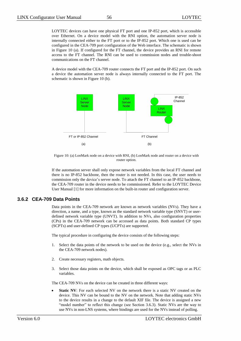
LINX Configurator User Manual 56 LOYTEC
Version 6.0 LOYTEC electronics GmbH
LOYTEC devices can have one physical FT port and one IP-852 port, which is accessible
over Ethernet. On a device model with the RNI option, the automation server node is
internally connected either to the FT port or to the IP-852 port. Which one is used can be
configured in the CEA-709 port configuration of the Web interface. The schematic is shown
in Figure 10 (a). If configured for the FT channel, the device provides an RNI for remote
access to the FT channel. The RNI can be used to commission nodes and trouble-shoot
communications on the FT channel.
A device model with the CEA-709 router connects the FT port and the IP-852 port. On such
a device the automation server node is always internally connected to the FT port. The
schematic is shown in Figure 10 (b).
LINX
Server
Node
FT Channel
(b)
IP-852
Channel
LINX
Router
LINX
Server
Node
FT or IP-852 Channel
(a)
Figure 10: (a) LonMark node on a device with RNI, (b) LonMark node and router on a device with
router option.
If the automation server shall only expose network variables from the local FT channel and
there is no IP-852 backbone, then the router is not needed. In this case, the user needs to
commission only the device’s server node. To attach the FT channel to an IP-852 backbone,
the CEA-709 router in the device needs to be commissioned. Refer to the LOYTEC Device
User Manual [1] for more information on the built-in router and configuration server.
3.6.2 CEA-709 Data Points
Data points in the CEA-709 network are known as network variables (NVs). They have a
direction, a name, and a type, known as the standard network variable type (SNVT) or user-
defined network variable type (UNVT). In addition to NVs, also configuration properties
(CPs) in the CEA-709 network can be accessed as data points. Both standard CP types
(SCPTs) and user-defined CP types (UCPTs) are supported.
The typical procedure in configuring the device consists of the following steps:
1. Select the data points of the network to be used on the device (e.g., select the NVs in
the CEA-709 network nodes).
2. Create necessary registers, math objects.
3. Select those data points on the device, which shall be exposed as OPC tags or as PLC
variables.
The CEA-709 NVs on the device can be created in three different ways:
Static NV: For each selected NV on the network there is a static NV created on the
device. This NV can be bound to the NV on the network. Note that adding static NVs
to the device results in a change to the default XIF file. The device is assigned a new
“model number” to reflect this change (see Section 3.6.3). Static NVs are the way to
use NVs in non-LNS systems, where bindings are used for the NVs instead of polling.

LINX Configurator User Manual 57 LOYTEC
Version 6.0 LOYTEC electronics GmbH
Dynamic NV: For each selected NV on the network there is a dynamic NV created on
the device. Compared to static NVs, dynamic NVs do not change the XIF interface of
the device. The dynamic NVs are created by the network management tool. Currently,
only LNS-based tools can manage dynamic NVs. As for static NVs, with dynamic NVs
it is possible to use bindings instead of polling.
External NV: The selected NVs on the network are treated as external NVs to the
device. The device doesn’t create any NVs on the device, but instead uses polling to
read from those NVs and explicit updates to write to the NVs. Therefore, no bindings
are necessary for external NVs. For input data points using external NVs however, a
poll cycle must be configured. If not configured explicitly, a default poll cycle of 60
sec. is chosen. The default poll cycle can be changed in the project settings menu. Note,
that the receive timeout option cannot be used with external NVs.
Based on the NV the data point is derived from, the following kinds of data points are
created:
Simple NVs that hold only one scalar value, e.g., SNVT_amp: Those kinds on NVs are
represented as analog data points. The data points holds the current value, NV scaling
factors are applied.
Simple NVs based on an enumeration, e.g., SNVT_date_day: Enumeration types result
in multi-state data points. They represent the state of the NV.
Structured NVs that consists of a number of fields, e.g., SNVT_switch: All structured
NVs are represented as user point. That is, the data point is structured similar to the NV
it is based on. Beneath the user data point, the individual structure fields are presented
as “sub-data points”.
For more information on the different types of network variables and their implications
please refer to the application note in Section 16.2. For CPs the allocation type “File” is
used.
3.6.3 Static Interface Changes
The device can be configured to use static NVs. Unlike dynamic NVs, static NVs cannot be
created in the network management tool. They are part of the static interface and are usually
compiled into the device. When static NVs are used, the device changes its static interface
and boots with a new one.
Each time the static interface of the device changes (i.e., static NVs are added, deleted, or
modified), the model number is changed. The model number is the last byte of the program
ID. Thus, a change in the static interface results in a change of the program ID and a new
device template needs to be created in the network management tool. A new device
template usually means that the device has to be deleted and added again in the database.
All bindings and dynamic NVs have to be created again for the new device.
When the Configurator software is connected via LNS, it supports the process of changing
the device template for the new static interface. It automatically upgrades the device
template of the LOYTEC device in the LNS database and restores the previous bindings
and dynamic NVs. If the LOYTEC device is not configured with an LNS-based tool, this
support is not available. The new static interface is only available in a new XIF file or by
uploading the new device template into the database. For more information on the static
interface and device templates please refer to the application note in Section 16.2.
Important! It is not recommended to mix manually created, dynamic NVs outside the virtual
function block and static NVs. In this case, the Configurator is not able to restore all
manually created dynamic NVs.
The Configurator supports model number ranges for different projects. By assigning a
model number range to a configuration, the Configurator can draw a new model number

LINX Configurator User Manual 58 LOYTEC
Version 6.0 LOYTEC electronics GmbH
from within the specified range. This feature is useful, if different device classes shall be
deployed and the model numbers need to be coordinated between installers. In this case, the
installers can agree on ranges they are free to use. The model number range can be set on
the data points tab as shown in Figure 11.
Figure 11: Setting a model number range in for a project.
3.6.4 Limitations for Local CEA-709 Schedulers
CEA-709 schedulers and the CEA-709 calendar adhere to the LONMARK standard objects.
For CEA-709, certain restrictions exist that need to be kept in mind. Attached data points
can either represent an entire NV or individual elements of a structured NV. CEA-709
schedulers may have several different groups of data points attached, i.e., the value preset
may consist of more than one element. For example, a CEA-709 scheduler might schedule a
SNVT_temp and a SNVT_switch and have 3 elements in each value preset as depicted in
Figure 12.
Figure 12: Example value presets in CEA-709 schedulers.
Priorities of exception days in a CEA-709 scheduler range from 0 (the highest) to 126 (the
lowest). The value 127 is reserved as a default for weekdays.
Further, the implementation as LONMARK standard objects requires the use of configuration
properties. If the number of CEA-709 schedulers or their capacities for daily schedules and
value presets is changed, the resource and static interface of the CEA-709 port changes. The
resources reserved for LONMARK calendar and scheduler objects can be changed in the
project settings (see Section 5.1.3). When downloading a project, the software verifies if
sufficient resources have been configured. If it detects a problem, the user is notified to
update the project settings. The Auto-Set feature automatically selects the right amount of
resources.
3.6.5 Limitations for CEA-709 Alarm Servers
Local CEA-709 alarming supports only one alarm server object. This alarm server object is
represented by the device’s LONMARK node object and facilitates the SNVT_alarm2 output
network variable. Acknowledging alarms in the alarm server is adhering to the LONMARK
specification and relies on the RQ_CLEAR_ALARM mechanism.
3.6.6 Limitations for Local CEA-709 Trends
Local CEA-709 trend objects support trending multiple data points in all trend modes,
interval, COV, and trigger, including aligned intervals. The enable data point is also
supported. All data points can be NVs, registers or of any other technology. There is no
LONMARK object linked to the trend object. Consequently, trend data cannot be accessed
over a LONMARK mechanism.

LINX Configurator User Manual 59 LOYTEC
Version 6.0 LOYTEC electronics GmbH
3.6.7 Dynamic Polling in CEA-709
External input NVs in CEA-709 rely on polling. Static polling can be configured by setting
the pollcycle (see Section 3.1.2). In addition, this technology also supports dynamic polling.
If the data point Web UI or L-WEB requires a refresh on those NVs, which are otherwise
not used, polling is activated at the configured pollcycle. If those data points go out of
scope, the polling on the external input NVs is stopped. If no polling is needed at all, the
pollcycle setting can be left at zero.
Dynamic polling has no effect on static or dynamic input NVs. These NVs are supposed to
have bindings and rely on update events. If static polling is configured via the pollcycle, no
change of the pollcycle is made at run-time.
3.6.8 CEA-709 Data Points in Connections
All types of CEA-709 data points can be used in local and global connections. All CEA-709
data points can be sources for auto-generating target technology data points. There is a
special treatment of the SNVT_switch, which will generate a binary data point in the target
technology.
CEA-709 can also be a technology target for auto-generation (see Section 3.3.3). In this
case static NVs with SNVTs are created only. If the source is an input, an NVO will be
generated, otherwise an NVI. If the source data point is analog, the SNVT is chosen with
the best-matching engineering unit. In many cases there exist SNVTs in fixed-point and
floating point versions. The default can be edited in the CEA-709 project settings. If the
source is a multi-state data point, a SNVT_count is generated and the source state map is
used. If the source is a binary data point, a SNVT_switch is created. In the auto-generate
preview the user can review and change the desired SNVTs individually before generating
the data points.
3.7 BACnet Technology
3.7.1 BACnet Data Points
Data points in the BACnet technology are known as BACnet objects. They have a specific
type (e.g. analog input or binary output) and a set of properties, which describe the data
point more closely. The actual value is stored in the “Present_Value”.
On the device, there exist two classes of BACnet data points:
BACnet server objects (SO): These BACnet objects configured by the Configurator
software to be allocated locally on the device. These objects can be accessed by the
BACnet building control system or operating workstations. They support COV
subscriptions to deliver value changes in an event-driven way. Local server objects can
be created as AI, AO, AV, BI, BO, BV, MI, MO, MV, Accumulator, Pulse Converter,
Loop, Large Analog Value, Integer Value, Positive Integer Value, Character String
Value, Octet String Value objects.
BACnet client mappings (CM): For certain applications, it is necessary that the device
acts as a BACnet client. This functionality can be configured by activating a client
mapping. Client mappings can be of the type Poll, COV, Write, Auto or Value. This
specifies how the BACnet client accesses other BACnet objects on the BACnet
network. The Auto method determines the best way (poll, COV, or write) to talk with
other server objects. Poll is used for objects that need to read data from other BACnet
objects in a periodic manner. COV is used to subscribe for COV at other BACnet
objects in order to get updates in an event-driven fashion. Write is used to send updates
to other BACnet objects. Value refers to a combined read and write client mapping.
When writing a value to this client mapping, the value is written to the remote BACnet

LINX Configurator User Manual 60 LOYTEC
Version 6.0 LOYTEC electronics GmbH
object. As soon as the Present_Value of the remote BACnet object is updated, the value
is transferred back.
The direction of BACnet server objects deserves a closer look. The direction specified for
data points in the Configurator software always refers to the network view of the
communication. The definition of input and output objects in BACnet, however, refers to
the process view, which is opposite to the network. Therefore, a BACnet analog input (AI)
object is modeled as an analog output data point. The direction of client mappings naturally
refers to the network communication. Therefore, a write client mapping is represented as an
analog output data point.
In BACnet commandable objects can be written with values at a certain priority. The value
with the highest priority is in effect. When revoking a written value, the NULL value is
written. This takes back the value. When all written values are withdrawn, the
Relinquish_Default value is in effect.
For BACnet server objects the write priority defines which priority is written to the
commandable server object. It is possible to create additional priority write data points,
which can be configured to write at other priority levels. This may be necessary, if two parts
of an application are required to write with two different priorities. To know, which priority
slots are used in a commandable object, additional priority read data points can be added.
They reflect the value on a given priority slot.
The default value feature of a data point is mapped to the Relinquish_Default property for
commandable objects. For BACnet objects, which are not commandable, the Present_Value
is initialized with the specified default value.
Analog BACnet objects have no fixed network unit. Depending on the chosen unit system,
the analog BACnet object will be created with the specified metric (SI) or U.S. unit in the
Engineering_Unit property. This means that the BACnet server object changes its
representation on the BACnet network (i.e., engineering unit and value), when the unit
system is changed on the device.
3.7.2 BACnet Alarming
BACnet alarming on the device is based on the intrinsic reporting mechanism. Currently,
algorithmic reporting is not supported. Alarm conditions can only be applied to data points,
which map to BACnet server objects. If defined, the intrinsic reporting properties of the
underlying BACnet objects are enabled. Alarm conditions can be specified for analog input,
output, value objects (AI, AO, AV), for binary input, output, value objects (BI, BO, BV),
and for multi-state input, output, value objects (MSI, MSO, MSV). With BACnet intrinsic
reporting alarm conditions on binary output (BO) and multi-state output (MSO) can only be
feedback alarms.. These restrictions do not apply, if the alarm condition reports to a generic
alarm server.
Alarm servers in the BACnet technology are mapped to BACnet Notification Class (NC)
objects. Each alarm server is mapped to one NC. The notification class number can be
configured in the object instance number property of the alarm server object.
Remote alarms in the BACnet technology refer to a remote NC object. When the device
starts up, the remote alarm object reads out the current alarm state of the remote NC and
reporting objects. To get notified about alarm transitions during run-time, the device
registers in the Recipient_List of the remote NC object.
Some BACnet devices do not send a usable text in their alarm notification messages. For
those devices the alarm client provides the option Ignore alarm message text. If this option
is enabled, the alarm client ignores the message text of an alarm notification and reads the
description property of the alarmed object instead.

LINX Configurator User Manual 61 LOYTEC
Version 6.0 LOYTEC electronics GmbH
3.7.3 BACnet Schedulers and Calendars
BACnet schedulers and the BACnet calendar adhere to the standard schedule and calendar
object in BACnet. For each scheduler a BACnet Schedule object is created. The calendar
deserves a closer look. For each calendar pattern a BACnet Calendar object is created. The
visible calendar on the Web UI is therefore a collection of BACnet calendar objects. Each
calendar pattern therefore is associated with a BACnet object instance number. The
calendar pattern “Holidays” is for example visible as CAL,1 on the BACnet port.
The BACnet schedule object allows only objects of one selected data type to be scheduled.
Therefore, schedulers on BACnet can only schedule one class of data points (e.g., only one
group of analog data points). As a consequence, the value preset in BACnet always has only
one element. The name of the value preset is not stored in BACnet. It is not accessible over
the BACnet network, either. Therefore, a default name is created, such as ‘22 °C’ for an
analog value. An example of two scheduled BACnet objects is shown in Figure 13. With the
extended BACnet features enabled in the project settings, a preset label can be assigned to a
specific scheduled value. For example the value ’16 °C’ can be assigned ‘night’. Click in
the column header and type the desired text.
Figure 13: Example value presets in BACnet schedulers.
Priorities of exception days in a BACnet scheduler range from 1 (the highest) to 16 (the
lowest). Weekdays in BACnet have no priority.
Changing the number of calendar patterns in a BACnet calendar can only be done through
the configuration software and not during run-time. The individual calendar pattern entries
in the calendar patterns can be changed at run-time. Therefore, it is advisable to reserve a
suitable number of calendar patterns in a BACnet calendar and leave them empty if not
needed immediately.
3.7.4 BACnet Trend Logs
Trending in the BACnet technology is based on the BACnet TrendLog object. A number of
restrictions apply to trend log objects in BACnet. Trend log objects must be created by the
Configurator software. These objects are accessible over the BACnet network for other
BACnet devices and operator workstations (OWS). All configuration properties can be
modified by the Configurator software as well as an OWS. The number of trend log objects
cannot be changed at run-time. Therefore, if it is intended that an OWS configures the trend
logs, a suitable number of empty trend log objects (i.e., without attached data points) must
be created in the Configurator software.
In BACnet trend logs, only one data point can be trended per trend log object. The trended
data point can be either a local BACnet server object or a remote BACnet object accessed
through a client mapping, showing the referenced property for trending to the OWS. Data
points of other technologies and the min/max/avg algorithms can be trended as generic data
points without having a BACnet property reference.
BACnet trend logs support interval, COV and trigger-mode logs, aligned intervals are
available in interval mode. The setting linear and ring-buffer logging is mapped to the
Stop_When_Full property of the underlying BACnet trend log object. This setting in the
Configurator software is a default and can be overridden by writing to the Stop_When_Full
property by the OWS. The trend log object adheres to BACnet revision 12.

LINX Configurator User Manual 62 LOYTEC
Version 6.0 LOYTEC electronics GmbH
If an enable data point is configured by the Configurator software, the Log_Enable property
is written with the value of that data point. If no enable data point is configured, the
Log_Enable is TRUE as a default and can be modified over the network.
The fill-level action is mapped to generating a buffer event notification in the BACnet trend
log object. The fill-level trigger can still be used for e-mails even if no notification class is
configured in the BACnet trend log object. The fill-level percentage maps to the
Notification_Threshold property. The percentage setting in the Configurator software is a
default and can be changed by the OWS over the network.
The Notify_Type and Notification_Class BACnet properties are usually written by the
OWS. If they shall be defined by the data point configuration, configure the Notify Type
and Notification Class data point properties on the trend log object to non-default values.
When doing so, the OWS can no longer change them permanently.
The BACnet technology also supports remote trend logs. A remote trend log is basically a
BACnet trend log client, which accesses trend data on another device. The remote trend can
load the trend data from the remote device and supply it to L-WEB or the trend CSV files.
3.7.5 Dynamic Polling in BACnet
Reading client mappings in BACnet rely either on COV or on polling. Static polling can be
configured as a fallback, if COV is not supported, by setting the pollcycle (see Section
3.1.2). Data points which are not used by other objects do not subscribe via COV or
perform polling. In addition, this technology also supports dynamic polling. If the data point
Web UI or L-WEB requires a refresh on those client mappings, COV subscriptions are
made or polling is activated at the configured pollcycle. If those data points go out of scope,
the polling on the remote BACnet object stops and COV is unsubscribed.
If no static polling is needed at all, the pollcycle setting can be left at zero in the client
mapping. In this case, only a COV subscription is made, if the device supports COV. If
COV is not supported, polling is only started, as soon as the values are required. This is
especially important on MS/TP channels with devices, that do not support COV.
3.7.6 BACnet Data Points in Connections
BACnet data points can be used in local and global connections. In BACnet commandable
objects can be written with values at a certain priority. The value with the highest priority is
in effect. When revoking a written value, the NULL value is written. This takes back the
value. When all written values are withdrawn, the Relinquish_Default value is in effect. In
other technologies there is no notion of taking a value back. To model this behavior, a
distinctive invalid value can be written to such a data point. For those data points that do not
an intrinsic invalid value, it can be specified when editing the data point. To make a
BACnet object convey that invalid value to the opposite side, enable the property
Relinquish to Invalid.
BACnet data points can be auto-generated from other data point sources (see Section 3.3.3).
Only BACnet server objects can be generated and the connected value is reflected in the
Present_Value property. Which type of BACnet object is created depends on the type of the
source data point or of the source structure member. For analog sources, analog objects are
created. The best-matching BACnet engineering unit is chosen. Other properties of analog
objects are copied from the source data point, including min and max present value. Multi-
state objects are created for source enumeration types. Which state IDs exist is documented
in the BACnet multi-state texts array. This information is copied from the source and made
compatible with BACnet restrictions by renumbering state IDs.
Normally BACnet AI, BI, MI are created out of input source data points and AO, BO, MO
out of output source data points. The BACnet project settings allow changing this default to
BACnet value objects AV, BV, MI. In the auto-generate preview the user can review and
change those object types individually before generating the data points.

LINX Configurator User Manual 63 LOYTEC
Version 6.0 LOYTEC electronics GmbH
3.7.7 Native BACnet Objects for I/Os
L-IOB I/Os can optionally be directly exposed to BACnet server objects. In this case, each
L-IOB I/O object is represented by one BACnet object. The mapping does more than a
regular data point connection for the sensor/actuator value. All relevant I/O configuration
properties are mapped to corresponding BACnet properties and reflect actual input/output
values, I/O status, override/manual values, operating mode, inversion and adhere to all
prescribed BACnet functions.
The type of the created BACnet server object depends on the type of the live value I/O data
point. If e.g. a universal input (UI) is used for measuring an analog value, the type of the
live value (Input data point) will be Double and thus, an Analog Input (AI) BACnet object
will be created. Table 4 shows all possible native BACnet object types for I/Os.
I/O I/O Live Value Type BACnet Object Feedback Object
DI/UI Double Analog Input (AI) or
Accumulator
-
DI/UI Boolean Binary Input (BI) -
DI/UI LIOB/MagCard Analog Input (AI) -
AO/DO Double Analog Output (AO) Analog Input (AI)
AO/DO Boolean Binary Output (BO) -
Table 4: Native BACnet object types for I/Os
A property relation ‘native’ (see Section 3.1.12) is added to the original L-IOB input or
output data point, which links to the created native BACnet data point. For an AO object, an
additional AI object is generated as the feedback value object. The data point of the AO
object has a ‘feedbackValue’ property relation that points to the feedback AI object. For
BO objects, a separate feedback object is not required, since a feedback value is already
included in the BACnet BO object.
For the STId Card Reader mode (see Section 3.5.2), the I/O live value type of the Card Data
input is an array of 40 nibbles which contains the last read Card ID in BCD encoding
(LIOB/MagCard). In this case, the first n BCD digits that form a number which can be
displayed by a BACnet float are written to the Present_Value of the created BACnet AI
object. An ASCII version of the entire BCD code is written to the Description property of
the BACnet object.
For the “Pulse Count” interpretation of inputs (see Section 3.5.1.4), it is possible to choose
between an analog input or an accumulator object in the Configurator. The main difference
is that accumulator objects can precisely represent 32-bit meter data while analog objects
suffer from a loss of resolution.
When using native BACnet objects for L-IOB outputs, the BACnet priority array concept is
used in the I/O operating mode ‘Auto’ for determining the physical output value. Other I/O
operating modes (‘Override’, ‘Manual’, ‘Disabled’, see Section 3.5.1.9) bypass the BACnet
priority array. The physical value is determined by the override value or manual value in
this case. The following L-IOB live value and configuration property data points, which can
be changed at run-time, are exposed to BACnet properties:
Input: For L-IOB inputs in ‘Auto’ mode, the input value is written to the
Present_Value property of the BACnet input object. When switching from another
operating mode to ‘Auto’, the current input value is also written.
Output: The output value written by the controller application to the BACnet output
object is reflected at the automatic priority in the Priority_Array of the BACnet object.
The resulting Present_Value of the BACnet object is then written to the physical output
in ‘Auto’ mode.

LINX Configurator User Manual 64 LOYTEC
Version 6.0 LOYTEC electronics GmbH
OperatingMode:
o Auto: The BACnet object is in normal operation as described above.
Out_of_service and OVERRIDDEN flags of the BACnet object are cleared.
o Override (Input): The BACnet input object is set to out-of-service. The
Present_Value no longer reflects the physical L-IOB input value. The L-IOB
override value is coupled to the Present_Value and vice-versa. Writing the
Out_Of_Service property over the BACnet network can turn the ‘Override’
mode on or off (except if in ‘Manual’ or ‘Disabled’ mode).
o Override (Output): The BACnet output object is set to out-of-service. The
Present_Value no longer writes to the L-IOB output value. The L-IOB
override value is coupled to priority slot ‘1’ and vice-versa. It is removed from
priority slot ‘1’ when returning to ‘Auto’ mode. Writing the Out_Of_Service
property over the BACnet network can turn the ‘Override’ mode on or off
(except if in ‘Manual’ or ‘Disabled’ mode).
o Manual: The BACnet object is set OVERRIDDEN. The Present_Value
reflects the manual value and is decoupled from the L-IOB input value (input)
or Priority_Array (output). Out_Of_Service is not set. The Out_Of_Service,
Present_Value, and Reliability properties are made read-only and can no
longer be written over BACnet. This mode cannot be modified over the
BACnet network.
o Disabled: The BACnet object is set out-of-service, the OVERRIDDEN flag is
set, and the reliability is set to ‘no fault detected’. The Out_Of_Service,
Present_Value, and Reliability properties are made read-only and can no
longer be written over BACnet. This mode cannot be modified over the
BACnet network.
OverrideValue: In ‘Override’ mode this value is written to the Present_Value of the
BACnet object at priority ‘1’. When entering ‘Override’ mode, the current override
value is written. When leaving ‘Override’ mode, NULL is written at priority ‘1’ for
output objects and nothing is done for input objects. For input objects in ‘Override’
mode, the override value is updated by the Present_Value when written over BACnet.
ManualValue: In ‘Manual’ mode, the L-IOB manual value is written to the
Present_Value property of the BACnet object. The Present_Value cannot be written
over BACnet in ‘Manual’ mode.
DefaultValue: The L-IOB default value is written to the Relinquish_Default property
of the BACnet object and vice-versa, if it exists.
Invert: This L-IOB parameter is written to the Polarity property of BACnet BO and BI
objects and vice-versa.
IOStatus: The I/O status is reflected in the Reliability property of the BACnet object:
o NO_FAULT_DETECTED: If the I/O does not report any error.
o NO_OUTPUT/NO_SENSOR: If an output or sensor failure is detected.
o COMMUNICATION_ERROR: If the L-IOB host reports a communication
error.
o UNRELIABLE_OTHER: For all other problems.
Feedback: For L-IOB outputs in digital mode, the feedback value is written to the
Feedback_Value property of the BACnet BO object. For L-IOB outputs in analog
mode, the feedback value is written to the dedicated BACnet AI object, which is
pointed to by the ‘feedbackValue’ property relation.
MinValue, MaxValue, Resolution: For analog BACnet objects and BACnet
Accumulator objects, these L-IOB configuration properties are written to the
corresponding BACnet properties when they change. For a BACnet Accumulator

LINX Configurator User Manual 65 LOYTEC
Version 6.0 LOYTEC electronics GmbH
object, the L-IOB Resolution is mapped to the BACnet Scale property. The BACnet
properties are read-only from the BACnet network.
I/O Name and Description: Initially, the BACnet server object name and description
are both set to e.g. ‘L1_1_UI1’ (for UI1), where the preamble is ‘L1_1’ for local I/Os
and ‘L2_1’ for an attached LIOB-55x device. In the Configurator, the BACnet server
object name and description can later be modified manually or synchronized with the
current I/O name and description.
PulseCountInit: If the BACnet object type is Accumulator and this L-IOB
configuration property is written (to reset the pulse counter), the value is also written to
the Value_Set property of the BACnet Accumulator object and vice versa.
3.8 IEC61131 Variables
IEC61131 variables are used to exchange data with the IEC61131 program. These variables
are represented in the data point configuration as register data points and can be connected
to other data points, e.g. to CEA-709 NV points, via data point connections.
In contrast to CEA-709 or BACnet variables, IEC61131 variables are always represented as
single data point. In case of scalar values (representing CEA-709 scalar or enumeration
types) one of the following basic data types might be used:
Double: A register of base type double is represented by an analog data point. It can
hold any scalar value. No specific scaling factors apply.
Signed Integer: A register of base type signed integer is represented by a multi-state
data point. This register can hold a set of discrete states, each identified by a signed
stats ID.
Boolean: A register of base type boolean is represented by a binary data point. This
register can hold a Boolean value.
Structured IEC61131 variables, representing for example structured NVs, or customer
defined IEC61131 structures, are stored as user type:
User: A user data point contains un-interpreted, user-defined data. The data is stored as
a byte array. A user data point does not include any other meta-data. This type of data
point also serves as a container for otherwise structured data points and represents the
entire data structure. User data points can only be connected to other user data points of
the same data length.
3.9 Regular Expressions
Some features of the Configurator use regular expressions to perform complex operations
on text. These apply to data point filters, naming rules and folder copy and rename. A
regular expression is a pattern that describes a set of strings. It is applied to an input text
and performs pattern-matching by evaluating the expression string consisting of literal
characters to match and meta-characters. Literals match themselves (abc matches exactly
‘abc’) whereas meta-characters may match one or more characters of the input text. The
available metacharacters are listed in Table 5. Regular expressions can handle
abbreviations, such as \d instead of [0-9]. The abbreviations provided are listed in Table
6.

LINX Configurator User Manual 66 LOYTEC
Version 6.0 LOYTEC electronics GmbH
Meta-Character Meaning
. Matches any single character.
[ ] Indicates a character class. Matches any character inside the brackets (for example, [abc]
matches ‘a’, ‘b’, and ‘c’).
^
If this meta-character occurs at the start of a character class, it negates the character class. A
negated character class matches any character except those inside the brackets (for example,
[^abc] matches all characters except ‘a’, ‘b’, and ‘c’).
If ^ is at the beginning of the regular expression, it matches the beginning of the input (for
example, ^[abc] will only match input that begins with ‘a’, ‘b’, or ‘c’).
- In a character class, - indicates a range of characters (for example, [0-9] matches any of the
digits ‘0’ through ‘9’).
? Indicates that the preceding expression is optional: it matches once or not at all (for example,
[0-9][0-9]? matches ‘2’ and ‘12’).
+ Indicates that the preceding expression matches one or more times (for example, [0-9]+
matches ‘1’, ‘13’, ‘666’, and so on).
* Indicates that the preceding expression matches zero or more times.
??, +?, *?
Non-greedy versions of ?, +, and *. These match as little as possible, unlike the greedy
versions which match as much as possible. Example: given the input ‘<abc><def>’, <.*?>
matches ‘<abc>’ while <.*> matches ‘<abc><def>’.
( ) Grouping operator. Example: ([0-9]+,)*[0-9]+ matches a list of numbers separated by
commas (such as ‘1’ or ‘1,23,456’).
{ } Indicates a match group. The actual text in the input that matches the expression inside the
braces can be retrieved through the sequence \0, \1, etc.
\
Escape character: interpret the next character literally (for example, [0-9]+ matches one or
more digits, but [0-9]\+ matches a digit followed by a plus character). Also used for
abbreviations (such as \a for any alphanumeric character; see Table 6 below).
If \ is followed by a number n, it matches the n-th match group (starting from 0). Example:
<{.*?}>.*?</\0> matches ‘<head>Contents</head>’.
$ At the end of a regular expression, this character matches the end of the input. Example:
[0-9]$ matches a digit at the end of the input.
| Alternation operator: separates two expressions, exactly one of which matches (for example,
T|the matches ‘The’ or ‘the’).
! Negation operator: the expression following ! does not match the input. Example: a!b
matches ‘a’ not followed by ‘b’.
Table 5: Metacharacters in Regular Expressions.
Abbreviation Matches
\a Any alphanumeric character: ([a-zA-Z0-9])
\b White space (blank): ([ \\t])
\c Any alphabetic character: ([a-zA-Z])
\d Any decimal digit: ([0-9])
\h Any hexadecimal digit: ([0-9a-fA-F])
\n Newline: (\r|(\r?\n))
\q A quoted string: (\"[^\"]*\")|(\'[^\']*\')
\w A simple word: ([a-zA-Z]+)
\z An integer: ([0-9]+)
Table 6: Abbreviations for regular expressions
When performing a replace operation on an input text, match groups are used in the output
template. Match groups are delimited by curly braces containing a matching pattern. As an
example the regular expression {[0-9]?[0-9]}:{[0-9][0-9]} contains two match

LINX Configurator User Manual 67 LOYTEC
Version 6.0 LOYTEC electronics GmbH
groups. The first match group matches any combination of one or two digits. The second
matches any two-digit combination. To make the replacement effective, the entire regular
expression has to match. In the example the regular expression matches any one or two-digit
combination followed by a ‘:’ and by any two-digit combination.
Then the output is assembled by specifying an output template. In that output template, both
literal text and references to the match groups can be specified. The first match group is
denoted by \0, the second by \1 and so on. Using the output template ref\0-\1 on the
example expression, the following input texts will produce these results:
“ab1:22c” matches, replacement is “ref1-22”,
“foo22:11bar” matches, replacement is “ref22-11”,
“ab22:1c” does not match, no replacement results in “ab22:1c”.

LINX Configurator User Manual 68 LOYTEC
Version 6.0 LOYTEC electronics GmbH
4 The LINX Configurator
This Chapter gives step-by-step instructions on how to commission the LOYTEC device,
create a data point configuration with network variables, BACnet objects, how to expose
those data points to the automation server, and how to maps data points to other
technologies in the universal gateway.
4.1 Installation
4.1.1 Software Installation
The LINX Configurator must be used to setup the data point configuration of the LOYTEC
device. The Configurator is installed as a plug-in tool for all LNS-based network
management tools as well as a stand-alone tool (for systems without LNS).
System requirements:
LNS 3.1 SP8 U1, LNS 3.2 TE SP5, OpenLNS (for LNS mode),
Windows Vista, Windows 7, Windows 8 (64 bit) or Windows Server 2003 (32 bit),
Windows Server 2008, Windows Server 2012,
Internet Explorer 9 or higher.
The LINX Configurator can be downloaded from the LOYTEC Web site
http://www.loytec.com. When asked for the type of installation, there are two options to
choose from. Select Typical to install the required program files. Select Full to install the
LONMARK resource files along with the software. This option is useful, when the system
does not have the newest resource files.
4.1.2 Registration as an LNS Plug-In
If the a CEA-709 device model shall be configured using LNS-based tools (e.g., NL200 or
LonMaker), the LINX Configurator needs to be registered as an LNS plug-in. In the
following, the process is described for LonMaker TE. Otherwise, please refer to the
documentation of your network management tool on how to register an LNS plug-in.
To Register in LonMaker TE
1. Open LonMaker and create a new network.
2. Click Next until the plug-in registration tab appears in the Network Wizard. Select the
LOYTEC LINX Configurator (Version X.Y) from the list of Not Registered (see
Figure 14).

LINX Configurator User Manual 69 LOYTEC
Version 6.0 LOYTEC electronics GmbH
Figure 14: Select the Plug-in to be registered.
3. Click Register. The Configurator now appears in the Pending list.
4. Click Finish to complete the registration.
Figure 15: Select device templates for installation.
5. A dialog appears to optionally select the device templates to be installed. Deselect
unneeded device templates to speed up registration. Click OK to continue.
6. The selected device templates are added automatically and XIF files are copied into the
LNS import directory.
Note: If you are using multiple databases (projects) make sure you have registered the plug-in in
each project.
7. Under LonMaker Network Properties Plug-In Registration make sure that the
LOYTEC LINX Configurator (Version X.Y) shows up under Already Registered.

LINX Configurator User Manual 70 LOYTEC
Version 6.0 LOYTEC electronics GmbH
Figure 16: Check that the LINX Configurator is properly registered.
4.1.3 CEA-709 Operating Modes
The Configurator can be used in on-line, off-line, and stand-alone mode. On-line and off-
line mode refers to the 2 operating modes of your LNS network management software.
On-line Mode: This is the preferred method to use the Configurator. The network
management tool is attached to the network and all network changes are directly
propagated into the network. This mode must be used to add the device, commission
the device, extract the port interface definition, and download the configuration into the
device.
Off-line Mode: In off-line mode, the network management software is not attached to
the network or the device is not attached to the network, respectively. This mode can be
used to add the device using the device templates, create the port interface definition
and to make the internal connections.
Stand-alone Mode: The Configurator can also be executed as a stand-alone program.
This mode is useful for the engineer who doesn’t want to start the configuration
software as a plug-in from within network management software (e.g., NL-220,
LonMaker or Alex). Instead the engineer can work directly with the device when online
or engineer it offline.
4.2 Data Point Manager
The Configurator uses a central concept to manage data points. The data point manager is
located on the Datapoints tab as shown in Figure 17. It is used to select, create, edit and
delete data points. The dialog is divided into three sections:
The folder list (number 1 in Figure 17),
The data point list (number 2 in Figure 17),
And a property view (number 3 in Figure 17).

LINX Configurator User Manual 71 LOYTEC
Version 6.0 LOYTEC electronics GmbH
Figure 17: Data Point Manager Dialog.
4.2.1 Folder List
At the left is a list of folders which is used to sort the available data objects by their
category. There are a number of predefined folders available:
Imported: This folder has a number of sub-folders for different import methods:
o CEA-709 CSV File: This folder is used to display data points imported from
CSV files.
o CEA-709 LNS Scan: This folder is used to hold data retrieved from a
network database scan.
o CEA-709 Network Scan: This folder holds NVs scanned online from an
attached CEA-709 network.
o CEA-709 Devices from XIF: This folder holds sub-folders and NVs created
from XIF files.
o BACnet Network Scan: This folder is used to display data points retrieved by
an online scan of the BACnet network.
o BACnet EDE File: This folder is used to display data points imported from
an EDE file.
Data objects in the import folder are not stored on the device when the project is
downloaded. They represent data objects which are available on remote devices
and are shown here as templates to create suitable data objects for use on the
device by selecting the Use on Device option.
Filter Templates: This folder contains the created data point templates. They contain a
set of properties, which are applied to data points, when they are created on the device.
There is a sub-folder for filter templates specific to different technologies, e.g.
CEA-709.
LINX-XXX: This is the device folder of the L-INX (other device models are
represented by a respective folder name). It contains all the necessary data points which
constitute to the device’s configuration. These data points are created on the device
when the configuration is downloaded. The following subfolders may be present
depending on the particular model:
3
1
2

LINX Configurator User Manual 72 LOYTEC
Version 6.0 LOYTEC electronics GmbH
o Favorites: This folder contains freely configurable symbolic links to data
points, which may reside anywhere in the folder structure. This folder
represents a way to assemble an alternate logical view to the data point
hierarchy. This folder is also available on the Web UI or the LCD UI.
o System Registers: This folder contains system registers, which provide
information on the device itself.
o User Registers: This folder holds user-definable registers. These registers are
not visible on the underlying network and are intended for internal usage.
o Scheduler: This folder contains generic scheduler and calendar objects. These
provide technology-independent scheduling functionality. Any data point can
be alarmed using a generic scheduler object.
o Alarm: This folder contains generic alarm servers. These provide technology-
independent alarms. Any data point can be alarmed using a generic alarm
server.
o Trend: This folder contains generic trend log objects. These can record
historical values for any data points.
o CEA-709 Port: This folder contains data points, schedulers, calendars, trend
logs, statistics, and remote data points of the CEA-709 network technology.
See Section 4.2.2.
o BACnet Port: This folder contains data points, schedulers, calendars, trend
logs, statistics, and remote data points of the BACnet network technology. See
Section 4.2.2.
Global Objects: This top-level folder contains sub-folders that organize specific
application objects that operate on data points.
o E-mail Configuration: This folder contains e-mail templates. An e-mail
template defines the destination address and text body of an e-mail, which is
triggered by data points and may contain data point values or file attachments.
To create an e-mail template, select the folder and use the context menu.
o Math Objects Configuration: This folder contains math objects. Math
objects are used to perform a predefined calculation on a number of input data
points and write the result to a defined set of output data points. Each math
object contains one formula. To create a math object, select the folder and use
the context menu.
o Alarm Log Configuration: This folder contains the alarm log objects. Each
alarm log object creates a historical log of alarm transitions of one or more
alarm objects (alarm server or client). To create an alarm log, select the folder
and use the context menu.
Using the context menu on a folder, sub-folders may be created to organize the available
objects. If new objects are created automatically, they are usually placed in the base folder
and can then be moved by the user to any of his sub-folders. Note, that the folder structure
described above cannot be changed by adding or deleting folders at that level.
The context menu also allows editing folder properties. Choose Properties … from the
context menu to open a property editor. Change name and description there.
4.2.2 Network Port Folders
Each network port folder on the device has the same structure of sub folders. These sub
folders are:
Datapoints: This folder holds all data points, which are allocated on the network port.
To create a data point, select the folder and use the context menu.

LINX Configurator User Manual 73 LOYTEC
Version 6.0 LOYTEC electronics GmbH
Calendar: This folder is used to hold a locally available calendar object with its
calendar patterns (definitions of day classes like holiday, maintenance day, and so on).
Current devices allow one local calendar object. To create a calendar, select the folder
and use the context menu.
Scheduler: This folder is used for local scheduler objects. Each of these objects will
map to a local scheduler on the device’s network port. Configuring schedules through
these objects actually transfers schedule configuration data to the underlying scheduler
objects on the network port. To create a scheduler, select the folder and use the context
menu.
Alarm: This folder is used for local alarm server objects. Each of these alarm server
objects represent an alarm class, which other objects can report alarms to. Other
devices can use the alarm server object to get notified about alarms. To create an alarm
server object, select the folder and use the context menu.
Trend: This folder is used for local trend log objects. Each of these objects will be able
to trend data points over time and store a local trend log file. To create a trend log
object, select the folder and use the context menu.
Statistics: This folder contains registers, which provide communication statistics
specific to the network port.
Remote Devices: This folder is used to collect all remote calendars, schedulers, trend
logs, and alarm client objects, which were created from network scan data. For each
remote device, a subfolder will be created where the objects referencing this device are
collected.
4.2.3 Data Point List
At the top right, a list of all data objects which are available in the selected folder is shown.
From this list, objects may be selected (including multi-select) in order to modify some of
their properties. Click on the Include Subfolders button to show all data points of the
selected data point folder and all its sub-folders. This can be a convenient way for multi-
select across folders.
To filter for data point names, enter a search text into the Datapoint Name Filter text box
and hit Enter. A drop-down list holds the previously used filters available. Filters can also
specify name patterns for sub-data points using a dot. Typing the first dot expands all
filtered data points to the first sub-level. Continuing typing after the dot then filters on
names of those sub-data points. For example, typing “sw.val” selects all data points having
“sw” in their name, then expanding to their first sub-level and filtering all sub-data points on
that level having “val” in the name. For complex name filters, regular expressions may be
used (see Section 3.9).
The list order can be changed manually by drag-and-drop. Select one or more data points
and drag them to the desired position in the data point list. The data points will get a new
order number.
The list can be sorted by clicking on one of the column headers. For example, clicking on
the Direction column header will sort the list by direction. Other columns display
Datapoint Name, NV name, SNVT, Object Name, object Type and Instance number,
allocation (Alloc) of server object (SO) and/or client mapping (CM), number of attached
Client Maps, and the data point unique ID. To apply the current sort order as the new data
point order on the device, right-click on the column header and select Renumber
Datapoints. Alternatively, select from the menu Tools Renumber Datapoints.
The OPC column provides check boxes for each data point. If checked, the respective data
point is exposed to OPC on the device. Deselect the check box, if a data points shall not be
exposed to OPC. Note, that deselected data points do not add to the OPC tag limit.

LINX Configurator User Manual 74 LOYTEC
Version 6.0 LOYTEC electronics GmbH
The Param column provides check boxes for each data point. If checked, the respective
data point is exposed to the parameter file. The PLC in and PLC out columns provide
check-boxes, which define if data points are visible inside the IEC61131 PLC program as
input and output variables.
New objects may be created in the selected folder by selecting New Datapoint command in
the context menu of the data point list. A plus sign in the list indicates that the data point
contains sub-points. Clicking on the plus sign expands the view.
If an entry in the data point list denotes a reference to another data point (e.g., a scheduled
value reference beneath a scheduler object), right-click on that item and choose Go to
related data point in the context menu. This will navigate your selection to the referenced
data point.
For the alarming, scheduling, trending (AST) features, there are columns, which display
icons for data points that are attached to an AST function. See Table 7 for details.
Icon Data Point Usage
Data point is scheduled
Data point has an active alarm condition
Data point has an inactive alarm condition.
Data point has sub-data point with alarm condition.
Data point is a trigger for e-mails.
Data point used for trending.
Data point is a link.
Data point has sub-data points, which are links.
Table 7: Icons for used data points in the data point list view.
The data points in this list are color coded to make general information visible to the user
at-a-glance. The color coding is described in Table 8.
Color Coded Information
(yellow) Data point is user-created and can be downloaded to the device.
(blue) Data point is fixed on the device and cannot be edited, e.g. system
registers.
dark red Data point is user-created and its technology object (e.g. dynamic NV)
has been deleted. The data point, however, is still used in the
configuration. It will not work on the device until the technology object
is created again.
Table 8: Color coding used for data points in the data point list view.
4.2.4 Property View
When one or multiple data points are selected, the available properties are displayed in the
property view. Properties which are read-only are marked with a lock sign. When
applying multi-select, only those properties common to all selected data points are
displayed. According to the frequency of usage, different views for the properties are
provided. Basic Properties list the most frequently used ones. All Properties is a list of all
available properties for the data point. Depending on the network technology and data point
class, different properties may exist.The Name Filter in the properties tab allows quick
filtering of properties that have a matching text in their name. For example, type “OPC” to
filter the OPC Tag property.

LINX Configurator User Manual 75 LOYTEC
Version 6.0 LOYTEC electronics GmbH
Data point properties common to all technologies:
Datapoint Name: This is the technology-independent data point name. This name may
be longer than and different to the name of the native communication object (i.e.,
network variable). Data point names must be unique within a given folder. The
maximum length is limited to 64 ASCII characters.
Datapoint Path: This informational property specifies the entire path of the data point
within the data point hierarchy. The maximum length is limited to 64 ASCII characters.
Datapoint Description: This is a human-readable description of the data point. There
are no special restrictions for a description.
OPC Tag: If enabled, the data point will be exposed to OPC. If not enabled, this data
point does not contribute to the limit of OPC tags.
Parameter: If enabled, the data point will be exposed to the parameter file. Those data
points are visible to the LWEB-900 parameter view [5]. A parameter data point is also
persistent. See Section 3.1.5.
PLC in - Logic Variable: If enabled, the data point will be usable in the IEC61131
PLC program as an input variable. This is only available on the L-INX.
PLC out - Logic Variable: If enabled, the data point will be usable in the IEC61131
PLC program as an output variable. This is only available on the L-INX.
Use Pollcycle value as: For input data points, this property defines whether the input
shall use a receive timeout or be constantly polling. See Section 3.1.2.
Poll on Startup: For input data points this property defines, whether the data point
shall be polled once at start-up. Poll-on-startup can be enabled independently of the
poll cycle. See Section 3.1.2.
Pollcycle: For input data points, this property defines the poll cycle in seconds. Set this
property to 0 to disable polling. See Section 3.1.2.
Receive Timeout: For input data points, this property defines the receive timeout in
seconds. Set this property to 0 to disable polling. See Section 3.1.2.
Min Send: For output data points, this property defines the min send time in seconds.
See Section 3.1.2.
Max Send: For output data points, this property defines the max send time in seconds.
See Section 3.1.2.
Send-on-delta: For output data points this property defines, if value updates shall be
sent only once they meet the COV condition of the data point. For analog data points
the analog COV increment is used. If not checked, updates are always transmitted
according to min and max send times. See Section 3.1.7.
Use Linear Scaling: If this property is enabled, the analog values are pre-scaled from
the technology to the data point. This scaling is in addition to any technology-specific
scaling factors. If enabled, the properties Custom Scaling Factor and Custom Scaling
Offset accept the scaling factors. See Section 3.1.7.
Custom Scaling Factor, Custom Scaling Offset: These properties only exist, if linear
scaling is enabled. They apply to analog data points only. See Section 3.1.7.
Notify on any COV: This property defines, if a data point shall trigger an update only
when the value changes or on every write. If this is enabled, consecutive writes with the
same value do not trigger an update. If you want to convey every write, disable COV
on the data point. For analog data points, it will disable the Analog Point COV
Increment and trigger an update on any change of value.
Persistent: This property defines, if the last written value shall be stored as a persistent
value. Persistent data points restore that value after a restart from the persistent storage.
See Section 3.1.4.

LINX Configurator User Manual 76 LOYTEC
Version 6.0 LOYTEC electronics GmbH
Default Value: This property defines a default value (see Section 3.1.3). Enter a
default value to enable this feature in the data point. Delete the value entirely to remove
the default value. If no default value is defined, this property reads “N/A”. The default
is no default value.
Historic Filter: This property allows defining historic filters for the scalar data point.
See Section 3.4.6.
Point Type: This is the base data point type, e.g., “Analog Datapoint”.
Direction: This is the data point direction. Use input, output or value as directions.
Network Unit: For analog data points this property contains the definition of an
engineering unit of the scalar value as represented on the network, e.g., “°C”. A human-
readable text for the engineering unit is displayed and can be entered. If the unit is
known by the Configurator as a convertible unit, it is displayed with a green checkmark
(see Section 3.1.13).
Unit SI: If the data point has a convertible unit, a unit representation in the metric (SI)
system can be chosen. If the SI unit system is active, all values are converted to this
unit, e.g. °C. For a non-convertible network unit this option is not available.
Unit U.S.: If the data point has a convertible unit, a unit representation in the U.S.
system can be chosen. If the U.S. unit system is active, all values are converted to this
unit, e.g. °F. For a non-convertible network unit this option is not available.
Analog Datapoint Max Value: For analog data points this property contains the upper
limit of the supported value range. Note that this does not define an alarm limit.
Analog Datapoint Min Value: For analog data points this property contains the lower
limit of the supported value range. Note that this does not define an alarm limit.
Analog Datapoint Precision: For analog data points this property defines the number
of decimals. ‘0’ specifies an integer value. Display units may use this to format the
floating point value accordingly.
Analog Datapoint Resolution: For analog data points this property defines the
smallest possible value increment.
Analog Point COV Increment: This property is valid for analog input data points. It
specifies by which amount the value needs to change, before an update is generated. If
every write shall generate an update even when the value does not change, specify 0 as
the COV increment. If any value change shall generate an update, set the Notify on any
COV property.
Active Text: For binary data points this property defines a human-readable text for the
active state (true).
Inactive Text: For binary data points this property defines a human-readable text for
the inactive state (false).
Current State Map: For multi-state data points this property defines the multi-state
map. It must be set to a valid multi-state map or it points to User/UndefinedStates.
Click on to assign a state map.
State Count: For multi-state data points this property defines the number of discrete
states.
State Text: For multi-state data points this property defines a human-readable state
label for each state.
4.2.5 Tracking Data Point Usage
Data points can be used by other objects, such as connections, schedulers, math objects and
many more. To get an overview on data point usage, the data point list contains the column

LINX Configurator User Manual 77 LOYTEC
Version 6.0 LOYTEC electronics GmbH
Use. This column provides a usage counter of the individual data points. If usage is ‘0’ the
data point is not used by any other object.
If the usage count is larger than zero, choose the item Show Usage … from the data point
context menu. This opens up a report window showing the objects referring to the selected
data point. An example is shown in Figure 18.
Figure 18: Data point usage report.
Each line reveals an object using the data point. Select a line and click on the Go to data
point button . This will navigate yours selection to the reported object.
4.2.6 Managing Multistate Maps
Multistate data points have a descriptive set of state texts for their state IDs. To manage
those state IDs and state texts among many multistate data points, they refer to multistate
maps. Some technologies have a fixed set of such multistate maps others have freely
configurable multistate maps (e.g, user registers). Editing a multistate map affects all
multistate data points, which are using that particular map. It is not necessary to edit each
data point individually. For managing multistate maps go to the menu Tools Manage
State Maps … .
To Edit a Multistate Map
1. Click on the Configure button in the Current State Map property of a multistate
data point. This opens the multistate map manager as shown in Figure 19.
Figure 19: Select multistate maps in the multistate map manager.
2. Select a Category and an existing state map in the State Maps list and click on Select.
Maps that are fixed and cannot be changed are marked with a lock symbol .
3. Expand a state map line to see where this state map is used. Select the usage and click
the Go to Data Point button . This navigates to the data point.
4. If a new multistate map shall be created, click the Create State Map button .

LINX Configurator User Manual 78 LOYTEC
Version 6.0 LOYTEC electronics GmbH
5. In the Create New State Map dialog enter a state map Name.
6. Then enter the desired number of states and edit the state texts as needed and click into
the list of states. Edit state IDs and texts to your needs. Pressing Enter goes to the next
line. Finally click the Save button.
7. Select the newly created multistate map and click the Select button. The selected map
is now assigned to the data point.
4.2.7 Organizing Favorites
There is a special Favorites top-level folder in the device data point folder hierarchy. This
folder contains freely configurable symbolic links to data points, which may actually reside
anywhere in the folder structure. This folder represents a way to assemble an alternate
logical view to the data point hierarchy.
To configure favorites, select any data point from any location in the data point folder
hierarchy and drag it onto the favorites folder. This will create a data point link, which is
displayed in the data point list:
The link name can be edited to something different that the original data point name. The
contents of this folder are also available on the Web UI or the LCD UI. The link names are
displayed there. The data point links can also be individually exposed to the OPC server or
PLC program notwithstanding if their original source is exposed or not.
Furthermore, the user can create sub-folders in the favorites folder and beneath to build a
hierarchy of data point links. Folder links are, however, not allowed.
For editing links of favorites for a large number of data points, the Manage Favorites tab
in the property view area of the data point manager provides a fast solution. The data point
tree is replicated in that tab as shown in Figure 20. Select a folder and optionally click on
the button to include favorites in sub-folders. Enter a filter expression to Filter, which
applies to the favorite name. For example, enter ‘room1’ to display all favorites that contain
this as a sub-string.

LINX Configurator User Manual 79 LOYTEC
Version 6.0 LOYTEC electronics GmbH
Figure 20: Manage favorites tab.
To link favorites to other data points using the manage favorites tab, navigate to the desired
folder in the main folder tree of the data point manager and select the data point to be
linked. Drag the data point onto the Link Target column. For detaching links, use multi-
select on the desired favorites and click the detach button . On linked favorites you may
click on the button , which jumps to the linked data point in the data point list.
4.2.8 Managing Property Relations
Property relations can be linked to data points in various user dialogs (e.g. alarm condition
dialog). For editing links of property relations for a large number of data points, the
Manage Relations tab in the property view area of the data point manager provides a fast
solution. The data point tree is replicated in that tab as shown in Figure 21. Select a folder
and optionally click on the button to include property relations of data points in sub-
folders. Enter a filter expression to Filter, which applies to both the data point name and
relation type. For example, enter ‘feedback’ to display all feedback value property relations.
Figure 21: Manage relations tab.
To link property relations to other data points using the manage relations tab, navigate to
the desired folder in the main folder tree of the data point manager and select the data point
to be linked. Drag the data point onto the Is related To column. For detaching links, use
multi-select on the desired property relations and click the detach button . On linked
property relations you may click on the button , which jumps to the linked data point in
the data point list.
4.2.9 CEA-709 Properties
Apart from the common data point properties discussed in Section 4.2.4 the data points of
the CEA-709 technology have additional properties. Depending on whether a NV is local or
external (remote), the properties may vary.
NV Allocation: This property defines how a data point shall be allocated on the device.
Choices are “Static NV”, “Dynamic NV”, and “External NV”. If the allocation type
cannot be changed, this property is locked.

LINX Configurator User Manual 80 LOYTEC
Version 6.0 LOYTEC electronics GmbH
SNVT: This property defines the SNVT of the NV, e.g., “lux (79)”.
Invalid Value: This property defines the “invalid value” for the NV. If set, this specific
value will be interpreted as “invalid” in the data point. If known by the SNVT, the
invalid value is filled in. Otherwise, the user can specify an invalid value.
CEA-709 Mapping Information: This information is derived from the SNVT. It
defines how the NV contents are mapped to the data point.
NV Scaling A, B, C: These are the scaling factors known from the SNVT table. The
scaling factors are applied to translate a raw NV value into the scalar representation of
the data point.
Data Type: This is the basic NV data type. This is usually filled in from the SNVT
definition.
Local NV Member Index: This property specifies the NV member index within a
given functional block. This must be a unique index in the functional block, which
identifies the NV after other NVs have been added or removed from the interface.
Local/Remote NV Index: This property specifies the NV index. For local, static NVs
this is the NV index of the static NV. For external NVs, this is the NV index of the NV
on the remote device.
Local/Remote NV Name: This property specifies the programmatic name of the NV.
For local, static NVs this is the programmatic name of the static NV. For external NVs,
this is the programmatic name of the NV on the remote device.
Local/Remote Functional Block: This property specifies the programmatic name of
the NV. For local, static NVs, one of the reserved functional blocks can be selected.
Local/Remote NV Flags: This property specifies the NV flags. For local (static or
dynamic) NVs, the flags can be configured. For external NVs, these flags are only
informational.
Remove NV Information: For external NVs, this property contains the information on
the remote device and the NV selector on that device.
Remote Device ID: For external NVs, this property contains information on the remote
device by listing the program ID and location string.
Remote Device Address: For external NVs, this property contains the CEA-709
network addressing information to access the node, i.e., subnet, node, and NID.
Retry Count: For external NVs, this property defines the retry count. The default is 3.
Repeat Timer: For external NVs, this property defines the repeat timer in
milliseconds. The default is 96 ms.
Transmit Timer: For external NVs, this property defines the transmit timer in
milliseconds. The default is 768 ms.
LNS Network Path: If available from an LNS scan, this property specifies the LNS
network path of the device where the given NV exists.
LNS Channel Name: If available from an LNS scan, this property specifies the LNS
channel name of the device where the given NV exists.
4.2.10 BACnet Properties
Apart from the common data point properties discussed in Section 4.2.4 the data points of
the BACnet technology have additional properties. Depending on whether a server object
and/or a client mapping exists, the properties may vary.
Engineering Units: For analog BACnet server objects, this property defines the
engineering units from the BACnet standard. One of those units can be chosen from a

LINX Configurator User Manual 81 LOYTEC
Version 6.0 LOYTEC electronics GmbH
drop-down box, if this property is not locked. Depending on the active unit system, the
BACnet engineering units property is either metric (SI) or U.S.
Server Object Type: This property defines the BACnet object type of the underlying
BACnet server object. It can be changed within the class, i.e., for an analog data point,
the server object type analog input, analog output, or analog value can be chosen.
Commandable: This property defines, if the underlying BACnet server object is
commandable. For BACnet value objects (AV, BV, MSV) this property can be edited
to create commandable or non-commandable BACnet value objects.
Relinquish to invalid value: This property defines whether the data point maintains
the Relinquish_Default value, if the priority array is empty or assumes the invalid
value. By default, this property is false and the Relinquish_Default value is used.
Setting this property to true can be beneficial when used in a connection to withdraw a
value in another technology.
Server Object Name: This property defines the object name of the underlying BACnet
server object. It must be unique among all server objects. It can be up to 64 characters
and is read-only on the BACnet network by default. If the option to keep OWS values
is enabled in the BACnet project settings (See Section 6.1), this property is writeable
and the server object name is only initialized by this property. Any changes made by
the OWS will be kept also after a new configuration has been downloaded.
Server Object Instance No: This property defines the object instance number of the
underlying BACnet server object.
Server Object Description: This property defines the object description of the
underlying BACnet server object. It can be left blank.
Server Object Device Type: This property defines the object device type of the
underlying BACnet server object. It can be left blank.
Server Accumulator Offset Correction: This property is available for accumulator
objects only. It is activated as a default. It ensures that the written data point value is
corrected in the Present_Value as soon as the Value_Set property is written and
requests a certain Present_Value. That correction offset is then added to the written
data point value, e.g., when received over a connection.
Get Active Priority: Set this check box to let the data point reflect the active priority
of the local or remote BACnet object. The priority is a number between 1 and 16. This
property is only applicable for commandable BACnet objects.
Allocate Server Object: This Boolean property defines, if a server object shall be
allocated for the data point. This option is useful, when a local server object shall be
allocated for a client mapping.
Allocate Client Mapping: This Boolean property defines, if a client mapping shall be
allocated for the data point. This option is always set, if at least on client mapping is
attached.
Client Map Count: This property defines the number of client mappings attached to a
data point. A data point can have one read client map or n write client mappings.
Client Map [n]: This is a list of client mappings. The property shows a summary of the
client mapping parameters.
Client Confirmed COV: This Boolean property defines, if a client map subscribes
with the confirmed COV service. If not enabled, the unconfirmed COV is used.
Client Map Type: This property determines the type. It can be one of the following:
Poll, COV, Auto, Write, or Value (see Section 3.7.1).
Client Write Priority: For a write or value client map, this property defines which
priority is used for writing.

LINX Configurator User Manual 82 LOYTEC
Version 6.0 LOYTEC electronics GmbH
Remote Instance Number: This property specifies the object instance number of the
remote server object. The object type cannot be edited.
Value Read Mode: For value client mappings, this property defines the read mode:
Poll, COV, or Auto.
BACnet Notify Type: When set to ‘default’ the Notify_Type property is to be written
by the OWS. Change this to ‘Event’ or ‘Alarm’ to set the property via the data point
configuration.
BACnet Notification Class: If notify type is non-default, this property is enabled. It
sets the Notification_Class via the data point configuration.
BACnet Event Enable (To-XXX): If notify type is non-default, this property is
enabled. It sets the Event_Enable property via the data point configuration.
4.3 Project Settings
The project settings allow defining certain default behavior and default settings used
throughout the project. To access the project settings go to the menu Settings Project
Settings…. This opens the project settings dialog, which provides several tabs as described
in the following sections.
4.3.1 General
The general tab of the project settings as shown in Figure 22 contains settings independent
of the technology port. The settings are:
Project Name: This setting allows entering a descriptive name for the project.
Parameters managed by: This setting defines, which instance is managing data point
parameters. As a default, parameters are assumed to be managed by LWEB-900 and the
Configurator does not download parameter values to the device. If changed to
parameters managed by Configurator, the Configurator downloads parameter values
and merges parameter changes back into the configuration. This setting does not affect
L-IOB parameters, which are always managed by the Configurator. For more
information on data point parameters refer to Section 3.1.5.
L-IOB: Always ignore L-IOB manual/auto differences: Set this check box to ignore
differences in the manual mode parameter of L-IOB I/Os.
Device Configuration Download Default: This group of settings defines, how the
download of device configuration parameters shall proceed. If Download only data
point configuration is selected, the configuration download does not download
anything else than the data point configuration. If Ask is selected, the download will
pop up a dialog in which the user can choose what to download. If Download specific
is selected, the project settings of this dialog determine what is downloaded onto the
device. The individual items to download are selected by individual checkboxes below
the download option. As a default, the configuration download includes the schedules
and calendar patterns as well as L-WEB projects.
Background polling: Activate this option to permanently poll data points, even if they
have no pollcycle assigned. The data points are polled one-by-one. The poll rate can be
configured. This setting is not active by default. For more information on background
polling refer to Section 3.1.2.

LINX Configurator User Manual 83 LOYTEC
Version 6.0 LOYTEC electronics GmbH
Figure 22: General Project Settings.
Data Point Units: This setting defines which unit system is active in the Configurator.
Depending on the active unit system, SI units are displayed or U.S. units, as defined per
data point. This setting, however, influences only the display in the Configurator. If the
device shall be configured to run on this same unit system, set the check box This unit
system will be set on device on download. In this case each configuration download
will ensure the device runs on the selected unit system.
Important! If this effectively changes the unit system on the device, all persistent values are reset to
their default values converted to the respective unit system.
Auto snapshot: This setting is off by default. It can be enabled in the drop-down box
by selecting a time interval, which is used by the Configurator to produce configuration
snapshots. The user can jump back and forth between those snapshots. Snapshots can
also be made explicitly by clicking the snapshot button in the tool bar.
Value Data Points: Select this option to create data points in the old style with
“_Read” (input) and “_Write” (output) data points. Old configurations will have this
option set to continue creating data points using the same style. Newly created
configurations should not use this setting.
4.3.2 Data Point Naming Rules
The data point naming rules tab allows specifying how data point names are automatically
derived from imported or scanned objects on the network. For each technology a rule can be
defined, how individual components shall assemble the desired data point name. The
technology is chosen in the tree view. The name components are added by clicking on .
Then click on the name component and choose which content shall be assigned from a drop-
down menu. To remove a component, click on it and choose Remove from the drop-down
menu. An example rule is shown in Figure 23.

LINX Configurator User Manual 84 LOYTEC
Version 6.0 LOYTEC electronics GmbH
Figure 23: Adding components to naming rules
A Separator character can be defined, which is inserted between the data point name
components. As a default the underline ‘_’ is configured. The Preview shows how names
would look like with the chosen separator and name components.
The CEA-709 data point naming rules (see Figure 24) work on scanned network variables.
The preview shows how names would look like, when the check marks are modified. Note,
that changing the name components does not change already scanned NVs; this setting
affects only new scan results.
Use programmatic name, Use display name: This option decides how the data point
name is extracted from the NV. The programmatic name is the NV name from the XIF
file and is limited to 16 characters. The display name may be extracted from LNS,
which allows displaying a different, longer name than the programmatic name.
Add Subsystem Name via Filter: This line can be edited by adding LNS sub-system
components to the data point name. Click on to add another component. The first
subsystem1 is the one containing the device, the second subsystem2 the one containing
subsystem1, and so on. Click on the arrow symbol for editing a filter expression, which
defines how the sub-system text is transformed to the name component, e.g. copy the
last three characters. Examples for regular expressions can be inserted by clicking the
question mark symbol and selecting a transformation. In the preview section the
filter expression can be tested against an example text. For more information on using
regular expressions please refer to Section 3.9.
Figure 24: Data Point Naming Rules Project Settings.
4.3.3 System Settings
This tab is shown in Figure 25. It is available only with the newest firmware version and can
be used to configure the device through the Configurator. In the configuration tree on the
left-hand side the user can select certain groups of settings, e.g. Web server settings. The

LINX Configurator User Manual 85 LOYTEC
Version 6.0 LOYTEC electronics GmbH
dialog displays the settings of the selected group in the dialog area. The structure is similar
to the menu structure on the Web UI.
Under the port configuration tree, the user can enable or disable communication protocols
on the device’s ports. Enabled protocols are marked with a checkmark. Click on the
checkmark and toggle it. Note, that depending on the device model communication
protocols on other ports may be disabled.
The IP address settings cannot be changed in this dialog. The FTP server can not be
disabled in this dialog, either. This ensures that the Configurator can maintain connection to
the device.
Figure 25: Device Configuration Settings
The Upload button can be used to get the current device settings from the device and
display them in this dialog. The Download button can be used to explicitly transfer the
settings from this dialog onto the device. Those changes will be visible immediately on the
Web UI but take effect only after a reboot of the device.
Important! After downloading the device settings from this dialog the changes will be visible
immediately on the Web UI but the device needs to be rebooted to let the changes take
effect.
The Date/Time section allows defining automatic time zone configuration on the device
using the PC’s time zone database. Select the Enable automatic Time Zone and DST
check box and choose the appropriate setting from the drop-down list below as shown in
Figure 26. The timezone offset, start and end of DST are then configured accordingly on the
device.

LINX Configurator User Manual 86 LOYTEC
Version 6.0 LOYTEC electronics GmbH
Figure 26: Choose time zone information in system settings.
4.3.4 OPC
This tab is shown in Figure 27. It provides fields to configure OPC server tag naming and
poll timings.
Automatically structure imported data points for faster OPC browsing: This
option enables the automatic generation of sub-folders when using data points on the
device. A sub-folder is created for each scanned or imported device. This allows OPC
clients to browse the OPC tags in a hierarchical way.
Use delayed response: Devices with OPC clients can be configured to use delayed
response subscriptions. This is activated as a default.
OPC Pollcycle: If no delayed response is configured, this setting specifies the OPC
pollcycle.
Wait Time: If delayed response is configured, this setting defines the requested time to
wait for a change until a poll response is received. It effectively implements a heart
beat.
Hold Time: If delayed response is configured, this setting defines the requested time to
hold back with poll responses. It effectively limits the traffic.
Figure 27: OPC project settings.
4.3.5 Project Information
This tab is shown in Figure 28. It provides fields to enter additional information about the
project such as author name and a reference field. The comments text area allows entering
free text describing the project. For instance it can be used to document a revision history.
The fields Last Saved and Configurator Version are filled in when saving the project.
When creating a new project without having it saved for the first time, those fields are
empty.

LINX Configurator User Manual 87 LOYTEC
Version 6.0 LOYTEC electronics GmbH
Figure 28: Info tab in project setting.
4.4 Using the LINX Configurator
4.4.1 Starting Stand-Alone
Go to the Windows Start menu, select Programs, LOYTEC LINX Configurator and
then click on LOYTEC LINX Configurator. This starts the Configurator and the main
window with the data point tab is displayed.
If the LOYTEC device is not yet connected to the network, go to the Model menu and
select the device model to be configured. If the device is already connected to the network it
is recommended to connect the Configurator online to the device.
To Connect to a Device Stand-Alone
1. Select the direct connection method by clicking on the Connect to device button
in the tool bar of the main window. The connect dialog as shown in Figure 29 opens
containing the managed device connection templates.
Figure 29: Connection dialog.
2. To add a new device connection, click on the New Device Connection button or
select an existing connection in the tree on the left-hand side and click on the Duplicate
button .
3. Enter a name for the connection.

LINX Configurator User Manual 88 LOYTEC
Version 6.0 LOYTEC electronics GmbH
4. Enter the admin password. The default password is ‘loytec4u’ (older firmware versions
used ‘admin’).
5. Choose a Connection Type. Possible options are:
a. Web service (recommended): Firewall-friendly connection using HTTP or
HTTPS.
b. TCP/IP: This uses the IP protocols FTP and Telnet or SSH to connect to the
device.
c. CEA-709 (NIC): Connection via a LOYTEC CEA-709 network interface.
6. For IP-based connection methods enter the host name or IP address of the device.
Optionally, click on Use secure connection to enable encrypted SSH or HTTPS access
to the device.
7. If your device is located behind a NAT router or firewall, you may change the FTP,
Telnet, SSH, HTTP and HTTPS ports to your needs for accessing the device.
8. If the CEA-709 connection method is used, enter the CEA-709 address information and
choose a network interface.
9. Click on Save to store that connection.
Note: If you connect without having the connection settings saved, a dialog asks whether to use
the changed settings temporarily for this connection only. In this case the existing
connection is not altered.
10. Organize device connections into folders. To add a new folder, click on the New
Folder button and enter a folder name. Drag the new device connection onto the
new folder.
11. Click on Connect. This establishes the connection to the device.
4.4.2 Uploading the Configuration
To get the current data point configuration of the device, the configuration needs to be
uploaded. This will upload the entire configuration from the device, including data points,
NVs, registers, client mappings, schedules, etc.
To Upload a Configuration
1. Click on the Upload Configuration button
in the tool bar. The configuration upload dialog opens up as shown in Figure 30.
2. If the check box Automatically sync local dynamic NVs is enabled on a CEA-709
device, the Configurator uploads any manually created dynamic NVs and merges them
into the data point configuration.
3. Click on the button Start to start the transfer. This will upload the configuration of all
ports.
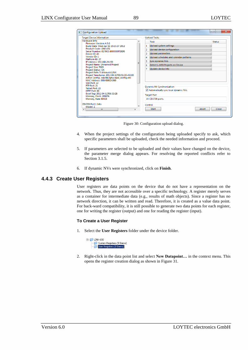
LINX Configurator User Manual 89 LOYTEC
Version 6.0 LOYTEC electronics GmbH
Figure 30: Configuration upload dialog.
4. When the project settings of the configuration being uploaded specify to ask, which
specific parameters shall be uploaded, check the needed information and proceed.
5. If parameters are selected to be uploaded and their values have changed on the device,
the parameter merge dialog appears. For resolving the reported conflicts refer to
Section 3.1.5.
6. If dynamic NVs were synchronized, click on Finish.
4.4.3 Create User Registers
User registers are data points on the device that do not have a representation on the
network. Thus, they are not accessible over a specific technology. A register merely serves
as a container for intermediate data (e.g., results of math objects). Since a register has no
network direction, it can be written and read. Therefore, it is created as a value data point.
For back-ward compatibility, it is still possible to generate two data points for each register,
one for writing the register (output) and one for reading the register (input).
To Create a User Register
1. Select the User Registers folder under the device folder.
2. Right-click in the data point list and select New Datapoint… in the context menu. This
opens the register creation dialog as shown in Figure 31.

LINX Configurator User Manual 90 LOYTEC
Version 6.0 LOYTEC electronics GmbH
Figure 31: Create a user register.
3. Enter a Datapoint Name for the register. You may leave the Register Name blank to
give the underlying register the same name as the data point.
4. For analog registers choose appropriate units for the metric (SI) and U.S. unit systems.
To specify a non-convertible unit type in the desired unit as a free text.
5. The standard setting is a value data point for read/write. Optionally, deselect the value
option and select the read data point or write data point check box. This is necessary
when configuring for an older firmware version.
6. Select Create as Parameter if needed. In this case, the register will be a persistent
parameter. It can be done later in the data point properties also.
7. Select a Type. Available are “Analog”, “Binary”, “Multistate”, “String”, “Variant” or
“User”.
8. When selecting User, a register with a user-defined structure is going to be created.
Click on next to Custom Type in order to select a structure type.
9. In the dialog Select Custom Type choose the type Category in the drop-down list and
the desired user type. Then click the button Select.
10. Click Create Register.
11. If needed create additional registers from the dialog. Finally, click Cancel to exit the
dialog.
4.4.4 Configuration Download
After the data points have been configured, the configuration needs to be downloaded to the
device. For doing so, the device must be online. If the device is not yet connected to the
network, the configuration can be saved to a project file on the local hard drive.

LINX Configurator User Manual 91 LOYTEC
Version 6.0 LOYTEC electronics GmbH
To Download a Configuration
1. Click on the Download Configuration speed button
in the tool bar of the main window. This will open the configuration download dialog
as shown in Figure 32.
2. If the project settings specify to ask (see Section 4.3.1), which specific parameters shall
be downloaded, check all that apply and click Ok.
3. Click Start to start the download. Each of the actions is displayed in the Task List
section of the dialog. The current progress is indicated by the progress bar below.
4. If parameters are selected to be downloaded and their values have changed on the
device, the parameter merge dialog appears. For resolving the reported conflicts refer
to Section 3.1.5.
5. When the download process has finished, a notification window appears, which has to
be acknowledged by clicking OK.

LINX Configurator User Manual 92 LOYTEC
Version 6.0 LOYTEC electronics GmbH
Figure 32: Configuration Download Dialog.
4.4.5 Upload the System Log
The system log on the device contains important log messages. Log messages are generated
for important operational states (e.g., last boot time, last shutdown reason) or errors at run-
time. This file is important for trouble-shooting and is also available on the Web. The file
can also be uploaded from the device with the Configurator.
To Upload the System Log
1. Connect to the device (see Section 4.4.1).
2. Click on the Upload system log button
in the tool bar. The upload system log dialog as shown in Figure 33 opens showing the
upload progress.
Figure 33: Upload system log dialog.

LINX Configurator User Manual 93 LOYTEC
Version 6.0 LOYTEC electronics GmbH
3. When the upload is finished, click on Show System Log. The system log window
appears as shown in Figure 34.
Figure 34: System log window.
4. Click on Save to store the system log into a file on your local hard drive.
4.4.6 Backup and Restore
The Configurator provides a backup and restore function for the connected device. It is
highly recommended to create a device backup once the device configuration has been
completed. This backup can be used in the case a device needs to be replaced in the
network.
To Create a Backup
1. Connect to the device (see Section 4.4.1).
2. Choose the menu Tools Backup Device Configuration ….
3. A file requestor opens. Choose a location to store the ZIP file of the device backup.
The suggested file name contains device IP address and creation date.
4. Click on Save. The backup is being uploaded.
To Restore a Backup
1. Choose the menu Tools Restore Device Configuration ….
2. In the file requestor choose a backup ZIP file and click Open.
3. The Configurator restores and reboots the device. The process is complete when the
device has finished rebooting.
4.4.7 Create Projects for SI and U.S. Units
Project engineering in the Configurator can be started using the unit system of choice, either
metric (SI) or U.S. From that point on, all values in the Configurator are displayed in the
chosen unit system.
For analog data points with a convertible network unit, the Configurator provides two unit
representations, one to be used in the metric (SI) system, and one used in the U.S. system.
The value is converted from the network unit to the unit of the chosen unit system. When
creating analog data points, both unit representations are chosen from the network unit as
appropriate. One can adapt these settings to the project’s needs.
Since both unit representations can be specified, a project can be engineered to run in a
metric (SI) and U.S. environment. Even when using a fixed data point configuration on the

LINX Configurator User Manual 94 LOYTEC
Version 6.0 LOYTEC electronics GmbH
device, it can be switched to the desired unit system. All values on the device are processed
in that chosen unit system, including Web UI, OPC server, parameter file, global
connections, and programmable logic.
To Start a Project In U.S. Units
1. In the Configurator menu go to Settings Project settings …
2. Click on the tab General.
3. Under Unit setting choose U.S. in the drop-down box. The check box This unit
system will be set on device on download is set as a default. This ensures the device
will run on the chosen unit system.
4. Click OK.
To Create Data Points in U.S. Units
1. Create a data point and choose the appropriate U.S. unit.
2. On existing analog data points, choose the appropriate U.S. unit in the data point
properties. Compatible units to the network unit are shown first. The active unit system
is indicated.
3. Enter all analog values such as default, min/max values, etc. in U.S. units. The unit is
indicated next to the data point property.
To Create Projects For Both SI and U.S. Units
1. On the General tab of the Project Settings dialog, deselect the check box This unit
system will be set on device on download. Choose your unit system of preference to
be used in the Configurator for the project design.
2. Create data points and choose both appropriate units for metric (SI) and U.S. unit
systems.
3. In program logic evaluate the system register Unit System in order to select
appropriate sets of coefficients for regulators.
4. Download the data point configuration to the device. The device can be switched to the
desired unit system using the Web UI or the system register Unit System Set.
Important! When changing the unit system, the device needs to be rebooted and will reset all
persistent values to their default values converted to the chosen unit system.

LINX Configurator User Manual 95 LOYTEC
Version 6.0 LOYTEC electronics GmbH
4.5 Connections
4.5.1 Create a New Connection
After having configured the device’s network ports with data points, internal connections
between those data points can be created. Usually, the manual method to create a
connection is used to create connections between different named data points.
A connection is an internal mapping in the device between input and output data points. A
connection always consists of one or more data points. A value update from an input data
point (sender) is distributed to all output data points (receivers). A status change of a
receiver data point is propagated back to all sender data points. All data points in the
connection must be of a compatible type or use an adaptor.
By adding data points as sender and receiver to the same connection, they transfer values in
both directions. Doing so with connected data points, bi-directional connections can be
built.
To manually create a new connection
1. Click on the Local Connections tab
2. in the main window and press the speed button Create new Connection. In the
menu choose Standard Connection. A new connection is added to the connection list.
Rename the connection if you want to do so.
3. Over the list Datapoints in connection on the right-hand side click on Attach Data
Point to add data points for this connection. This opens a list of all available data
points. Select one and press OK. You may use multi-select to select more than one data
point at a time.
Note: By default only compatible data points are displayed. Sometimes compatible data points
are available as member points (e.g., a SNVT structure member). Click on to expand
the data point and select the desired member point.
4. Now the connection tab contains the new connection and below the list of data points in
that connection as shown in Figure 35.
Figure 35: Connection tab with a connection and data points.

LINX Configurator User Manual 96 LOYTEC
Version 6.0 LOYTEC electronics GmbH
5. Change the direction by modifying Send or Receive. For changing multiple data points
use multi-select. Optionally, select Disable to temporarily exclude this data point from
communication in the connection.
6. For receive items you may optionally define a forward Delay in seconds (see Section
3.3.5).
7. If the attached data point needs a conversion, the item displays a yellow exclamation
mark and the default conversion (e.g. ‘Analog to CEA-709/motor_state_t’). By
clicking on the button to view the current conversion.
8. To add a new conversion to this item, click on the button. A dialog opens, which
displays the matching adaptors already available in the library as shown in Figure 36.
Figure 36: Choose a custom conversion.
9. Select an existing conversion, click the plus button to create a new conversion, or
click the edit button to modify an existing conversion.
10. An example for editing an analog to multi-state value conversion is shown in Figure 37.
Enter a Conversion name, then edit the Value range from column and select the
desired Target state mapping.
Figure 37: Edit an analog to multi-state conversion.
11. Click Save and then choose the newly created conversion by clicking Select.
12. The items with an assigned value conversion appears with a green checkmark .

LINX Configurator User Manual 97 LOYTEC
Version 6.0 LOYTEC electronics GmbH
To Create a Connection via Drag-and-Drop
1. Change to the Datapoints tab of the main window and navigate to the data point that
shall be put into the new connection.
2. In the properties view below the data point list click on the Local Connections tab as
shown in Figure 38.
3. Then simply drag a data point from the data point list and drop it onto an empty area in
the connections list as shown in Figure 38.
Figure 38: Create a connection with drag-and-drop.
4. To add data point to that connection, drop the new data point into the empty area in the
connected data points list below.
To Create a Bi-Directional Connection
1. Start the connection by adding a data point. A value data point is added as Send to a
new connection.
2. Then add the same data point a second time and do not create a multi-slot connection.
This time it is added as Receive. This makes the data point send to and receive values
from the connection.
3. Continue by adding the data point, which shall be connected. A value data point is
added as Receive to an existing connection.
4. Then add the same data point a second time to that connection. This time it is added as
Send.
5. Now both data points send values to and receive values from the connection. This
synchronizes value changes back and forth between the involved data points. Update
loops are suppressed by the connection. It is not necessary to set a COV on any of the
involved data points. An example is shown in Figure 39.
Figure 39: Bi-directional connection.

LINX Configurator User Manual 98 LOYTEC
Version 6.0 LOYTEC electronics GmbH
4.5.2 Create Connections from a CSV File
A quick way to perform batch edit on connections is to export and import connections from
the connections CSV file. Each line in the connections CSV file identifies a connection. The
first column is the connection name. The second column specifies the hub data point. The
full path to the data point must be specified using the dot ‘.’ as the folder separator. The
third and following columns specify the target data points.
To Create Connection from a CSV File
1. Select the menu Tools Export Local Connections …
2. Select an appropriate file name and export.
3. Edit the connections CSV file. An example is shown in Figure 40.
#connection_csv_ver,1
#ConnectionName,HubDPName,TargetDPName
Ai0,LINX-200.BACnet Port.ai0,LINX-200.User Registers.abs_humid1
Ai1,LINX-200.BACnet Port.ai1,LINX-200.User Registers.abs_humid2
Ai2,LINX-200.BACnet Port.ai2,LINX-200.User Registers.abs_humid3
Ai3,LINX-200.BACnet Port.ai3,LINX-200.User Registers.abs_humid4
Figure 40: Example Connection CSV File.
4. Select the menu Tools Import Local Connections …
5. If connections that are not part of the connection CSV file shall be deleted, click Yes
when prompted. Click No if the other connections shall be left as is.
6. Choose the file to import and click Ok.
7. When the import has completed, optionally view the log to check, which connections
have been added, modified, and deleted.
4.5.3 Modify Connections
Connections can be edited and deleted. This is also done in the Connections tab of the main
window. Editing connections does not influence the data point configuration. This means,
when deleting a connection or adding/removing data points to/from a connection, the data
points are not deleted.
To Edit a Connection
1. Change to the Local Connections tab of the main window.
2. Select the connection to edit. Then follow the steps as applied when creating a
connection.
3. To detach a data point from the selected connection, select the data point and click on
the button Detach selected data points over the connection member list.

LINX Configurator User Manual 99 LOYTEC
Version 6.0 LOYTEC electronics GmbH
4. Change the direction of a data point in the connection by choosing one from the Dir
drop-down. You may select Disable to temporarily exclude this data point from the
connection altogether.
To Add Data Points via Drag-and-Drop
1. Change to the Datapoints tab of the main window and navigate to the data point for
being added.
2. In the properties view below the data point list click on the Connections tab as shown
in Figure 41.
3. Select an existing connection.
4. Drag the selected data point and drop it into the empty area of the Datapoints in
connection list as shown in Figure 41. This adds the data point to the selected
connection.
Figure 41: Modify connections in the properties view.
5. To replace a data point in a connection drop the new data point right onto an existing
data point in the connection that shall be replaced.
To Delete a Connection
1. Change to the Local Connections tab of the main window.
2. Select the connection for removal. Use multi-select to select more than one connection.
3. Click on the button Delete Connection over the connections list.

LINX Configurator User Manual 100 LOYTEC
Version 6.0 LOYTEC electronics GmbH
4.5.4 Create a Multi-Slot Connection
A multi-slot connection can be used to connect a number of different data points together
under one umbrella. It can be considered as a cable with many wires, each wire represented
by a slot with a label. For example, one can create a multi-slot connection for a structured
data point, connecting each sub-data point to another technology. All those slots appear
under the same connection. But data point only exchange data, if they are added to the same
slot.
To Create a Multi-Slot Connection
1. Change to the Datapoints tab of the main window and navigate to the data point to be
connected.
2. Select a structured data point and drag it into the connections list to create a new
connection.
3. A dialog prompts the user, whether to create a multi-slot connection or use the user
data point as a single entity in the connection. Choose Yes to create a multi-slot
connection.
4. A multi-slot connection is created as shown in Figure 42. The multi-slot connection can
be collapsed or expanded. In the expanded view it shows all slots. Select the top-level
multi-slot connection to view all data points in the connection. Select a single slot
beneath to view only those data points in that slot.
Figure 42: Multi-slot connection.
5. Add more slots by dropping data points onto the top-level multi-slot connection
‘setting1’.
6. Connect other data points to the slots by dropping them onto the slots. For example
connect the register ‘regRotation’ by dropping it onto ‘setting1.rotation’ as depicted in
Figure 43.

LINX Configurator User Manual 101 LOYTEC
Version 6.0 LOYTEC electronics GmbH
Figure 43: Add data point to connection slot.
4.5.5 Create a Math Block Adaptor
When connecting structured data points the multi-slot connection can be used. If a simple
mapping of the sub-data points is not possible and a more advanced mathematical
conversion is required, a math block adaptor can be created. This math block is based on a
multi-slot connection with n inputs and m outputs (see Section 3.3.2).
To Create a Math Block Adaptor
1. Create a multi-slot connection from a structured data point, e.g., the input data point.
2. Add output slots to the multi-slot connection, e.g. by adding a structured output data
point. An example is shown in Figure 44.
Figure 44: Multi-slot connection for math block adaptor.
3. Click on the Create math adapter from connection button. The dialog Edit
Multi-Slot Math Adaptor opens as shown in Figure 45.

LINX Configurator User Manual 102 LOYTEC
Version 6.0 LOYTEC electronics GmbH
Figure 45: Edit a math block adaptor.
4. Enter a name and description for the adaptor.
5. For each output enter an Output Value Formula. This can be done by directly typing
the formula or by clicking the edit button .
6. Optionally, etner an enable formula into Write Output if Formula en > 0. As a default
enable is ‘1’.
7. When finished with the math block click Save.
To Use an Existing Math Block Adaptor
1. Click on the Local Connections tab
2. in the main window and press the speed button Create new Connection. In the
menu choose Connection with Math Adaptor.
3. In the dialog Select Multi-Slot Math Adaptor select an existing adaptor and click
Select. A new multi-slot connection is added to the connection list with empty slots as
depicted in Figure 46.

LINX Configurator User Manual 103 LOYTEC
Version 6.0 LOYTEC electronics GmbH
Figure 46: Created new multi-slot connection from math adaptor.
4. Now connect data points by dragging and dropping them onto the empty slots in the
data point list below.
5. To view the math conversion click the magnifier button .
4.5.6 Connection Overview
Select the Connection Summary tab to get a graphical representation of all connections. It
represents the two connected data points, their technology they are based on and the
direction of the connection. An example for the overview is shown in Figure 47.
Figure 47: Connections Summary.
4.5.7 Create a Global Connection
Global connections are an easy way to publish or subscribe to global data, which is
distributed among devices. To configure such communication, a device needs to be member
of a CEA-852 channel. Once it is member of that channel, global connections need to be
configured in the data point configuration. This is similar to creating local connections and
most of the configuration steps apply also for global connections. In addition, also network
timing parameters can be configured for global connections. For a description see Section
3.3.4.
If other devices already have global connections configured that publish data on the
network, their definition can be exported and imported into the new configuration. That will
make all the global connection names available. When creating manually, the connection
names can be edited.

LINX Configurator User Manual 104 LOYTEC
Version 6.0 LOYTEC electronics GmbH
To Create a Global Connection
1. Click on the Global Connections tab
2. in the main window and press the speed button Create new Connection. A new
connection is added to the connection list.
3. Define a name for the global connection. This name is required to be unique on the
network. Data will be published or subscribed to under this name.
4. Add data points to the global connection as described in Section 4.5.3. As a default,
output data points will be added as sending, input data point as receiving data under the
global connection.
5. Change the direction by modifying send or receive. For changing multiple data points
use multi-select.
6. Define timing parameters for a global connection that is sending out data. On the global
connections tab of the main window the connection properties are listed below the data
point member list. In the tab of the property area click the button .
7. To export the definitions of the created global connections, click the button Export
connections to disk and choose the XML format.
8. To use those definitions, click the button Import connections from disk and
choose an exported connections XML file. This creates the global connections structure
with connection names but without any data points. Data points can then be added, for
example, via drag-and-drop.
4.5.8 Automatic Generation of Connections
The smart auto-connect feature of the Configurator provides a quick way to automatically
generate target data points out of a source data point selection and generate connections to
them. Using this feature a gateway interface is generated with a few mouse clicks.
To Auto-generate Data Points and Connections
1. Go to the Datapoints tab.
2. Select those data points of a given port folder that shall be mapped to another
technology. The methods innclude sub-folders, data point name filter and multi-select
may be used for doing this.

LINX Configurator User Manual 105 LOYTEC
Version 6.0 LOYTEC electronics GmbH
3. Click on the speed button Generate and connect selected in the tool bar.
4. Alternatively, you can select the port folder or any sub-folder and click the speed
button Folder-wide Generate points and auto-connect in the tool bar. This
generates target data points and connections for all data points in the folder.
5. The auto-generate preview dialog opens as shown in Figure 48. Choose the target
technology. The preview results show a list for each source type found how it will be
created as a target type. The Type Name column provides a drop-down to modify the
result. This choice is remembered and will be applied the next time again. You may
click the Restore defaults button to revert all custom settings.
Figure 48: Auto-generate and connect preview.
Note: The respective port may have to be enabled first in the project settings to have the target
technology available in this dialog.
6. If the selected target technology offers choices on the direction to create, choose one of
the offered directions.
7. Structured data points will be flattened in some target technologies. To prevent this
from happening, click the Don’t expand structured data points button . Note, that
this may require an auto-generate template, which defines how to map this structured
data point.
8. Select an auto-generate template in the drop-down box of the Template column as
shown in Figure 49.
Figure 49: Auto-generate and connect with auto-generate template.
9. After having reviewed all types, click the Generate button.

LINX Configurator User Manual 106 LOYTEC
Version 6.0 LOYTEC electronics GmbH
Note, when auto-creating the target data points, the Configurator initializes their properties
with default values derived from the properties of the source data points. In particular, the
data point name, description, minimum and maximum value, and engineering units are
generated. If the default properties do not have the desired values, the user can edit them in
the target folder. The user can also craft an auto-generate template where those properties
are pre-set.
To auto-generate target data points into multiple technologies from the same source data
points, execute the auto-generate and connect function multiple times on the source data
points. Select different target technologies in sub-sequent auto-generate actions. The new
data points are added to existing connections. This makes it easier to keep track of auto-
generated local connections involving multiple technologies.
4.5.9 Create an Auto-Generate Template
If the implicit options for generating target types are not sufficient for the envisioned task, a
specialized auto-generate template can be crafted. This template contains copies of the
source data points as a starting point. The user can then create instances of the desired target
data points and use one or more connections (e.g., a multi-slot connection for sub-data
points of a structured source). The target data point name and description can contain
variable placeholders, which expand to the name and description of the actual sources,
which the auto-generate template will be applied on. If required, one can add conversion
adaptors including math blocks. The entire configuration serves as a template on how to
generate the target data points and apply the appropriate connections. Once saved in the
template library, it will be available for selection in the preview dialog.
To Create an Auto-Generate Template
1. Select the source data points and invoke auto-generation as described in Section 4.5.8.
2. In the preview dialog select the source type for which a new template shall be created
and click the Create template for selected source button.
3. The auto-generate template editor opens as shown in Figure 50. It contains two data
point lists. The left-hand (denoted ‘1’) list is pre-filled and contains the selected source
data points. They are locked and cannot be modified. The right-hand list (denoted ‘2’)
is intended for creating the desired target data points.

LINX Configurator User Manual 107 LOYTEC
Version 6.0 LOYTEC electronics GmbH
Figure 50: Auto-generate template editor.
4. Enter Name and Description, which is used later to select the auto-generate template.
5. Right-click in the target data point list and select Create Data Point …. The creation
dialog of the respective target technology opens. Create the desired target data points,
e.g., a BACnet ‘MO’ data point with a custom multi-state map.
6. Edit the target data point name to use a variable placeholder for the target data point
name such as %{name}. Insert the placeholder by selecting the desired entry of the add
var drop-down list. When applying the auto-generate template, the placeholder is
expanded to the name of the actual source data point. Choose %{path}%{name} to
flatten the folder tree of the source data point and include the path in the target data
point name.
7. Drag and drop the source and target data points into the Connections tab below to
create the needed connections. Add custom conversions to the connection items as
needed.
8. Click OK to store the auto-generate template.
9. From now on it can be selected in the Template column and applied to the source.
4.5.10 Create a Complex Auto-Generate Template
Simple auto-generate templates as described in Section 4.5.9 are based on single data point
sources. These can be scalar or structured data points. In any case the decision, which auto-
generate template applies, is based on that single data point. If a given set of source data
points shall generate another specific set of target data points, so-called complex auto-
generate templates can be used. These are based on folders that contain the described data
points (i.e., name and types must match). With a complex auto-generate template the entire
folder is used as a source and an entire target folder will be generated with the target data
points defined by the complex auto-generate template.

LINX Configurator User Manual 108 LOYTEC
Version 6.0 LOYTEC electronics GmbH
For example, there are device folders of similar devices on the BACnet port. These shall
serve as the connection source. One such device folder contains three analog data points
named ‘TempComfort’, ‘TempNight’, ‘RoomTemp’ that have ‘°C’ as engineering units.
These shall generate two target data points, one a structured data point with the setpoints
‘TempComfort’ and ‘TempNight’ connected (e.g. a SNVT_temp_setpts) and one data point
with the ‘RoomTemp’ connected (e.g., a SNVT_temp). A complex auto-generate template
is created based on one of the device folders.
To Create a Complex Auto-Generate Template
1. Select the source folder and invoke auto-generation as described in Section 4.5.8 using
the button Folder-wide Generate points and auto-connect in the tool bar.
2. In the preview dialog choose generation based on folder templates only. The list will
then be empty as no such template yet applies. Then click the Create template for
selected source button.
3. The auto-generate template editor opens as shown in Figure 50. It contains two data
point lists. The left-hand (denoted ‘1’) list is pre-filled and contains the selected source
data points. They are locked and cannot be modified. The right-hand list (denoted ‘2’)
is intended for creating the desired target data points.
4. Enter Name and Description, which is used later to select the auto-generate template.
5. Right-click in the target data point list and select Create Data Point …. The creation
dialog of the respective target technology opens. Create the desired target data points,
e.g., a SNVT_temp_setpts and a SNVT_temp.
6. Edit the target data point name and local NV name. Since the source data point names
will be equal for all source folders, an additional component may be added to the target
data point name. Use the variable placeholder %{path} in the name to make it unique.
Insert the placeholder by selecting the desired entry of the add var drop-down list.
When applying the auto-generate template, the path placeholder is expanded to the
actual folder path relative to the Datapoints folder.
7. Drag and drop the source and target data points into the Connections tab below to
create the needed connections. Add custom conversions to the connection items as
needed.
8. Click OK to store the auto-generate template.
9. From now on it can be selected in the Template column and applied to matching
source folders.
4.5.11 Managing Connection Resources
All described resources for connections, including connection adaptors and auto-generate
templates are part of the configuration project. When opening the project file on another
PC, all project resources will be merged into the local resource repository. After opening a
project file, all its resources are therefore available to new projects.

LINX Configurator User Manual 109 LOYTEC
Version 6.0 LOYTEC electronics GmbH
The Configurator provides a resource manager, that can be used to view, edit, import and
export connection resources. Select the menu Tools Manage Connection Adaptors …
or Tools Manage Auto-Generate Templates … to open the resource manager dialogs.
4.6 E-mail Templates
4.6.1 Create an E-mail Template
E-mail templates are used to assemble and transmit e-mails when certain trigger conditions
occur. The e-mail template contains the destination e-mail address, the subject, and text.
Variable parameters can be added to the text by using data point sources. The transmission
of an e-mail is triggered by one or more trigger data points. For setting up e-mails, the
e-mail account information has to be configured on the device, e.g., on the Web UI (see
Section E-Mail configuration in the LOYTEC Device User Manual [1]).
To Create an E-mail Template
1. Under the Global Objects folder, select the E-mail Configuration sub-folder.
2. Right-click and select New E-mail Template … from the context menu.
3. In the Configure E-mail Template dialog, which is shown in Figure 51 enter the To
address and the Subject. Optionally, Cc and Bcc addresses can be specified.
Figure 51: Configure E-Mail Template Dialog.
4. Enter text in the E-mail Text multi-line field.
5. If the e-mail text shall contain values of data points, add data points to the Data
Sources list by clicking the Add… button.
6. A data point selector dialog opens. Select one or more data points and click OK. The
selected data point appears in the Data Sources list.

LINX Configurator User Manual 110 LOYTEC
Version 6.0 LOYTEC electronics GmbH
7. If necessary, edit the Format string. The default ‘%.2f’ will format the value as a
floating point with 2 decimals. You may choose a different format string from a drop-
down list of pre-defined formats, including date/time formats.
8. Select the data point in the Data Sources list. In the drop-down box underneath select
Selected Data Source Value, in the next drop-down select to text click the Paste
button. Variables can also be pasted to the subject line or any of the address lines.
9. A place holder %{v1} for the data point value appears now in the e-mail text (see
Table 3 in Section 3.4.5).
10. To replace an existing data source select the data point in the Data Sources list and
click the Replace… button. This opens a data point selector dialog for choosing the
replacement data point.
4.6.2 Trigger E-mails
E-mail templates are used to assemble and transmit e-mails when certain trigger conditions
occur. For an e-mail template, one or more trigger conditions can be defined. The e-mail
will be sent, when one of the trigger conditions is activated. Depending of the trigger data
point type, the trigger conditions can be refined.
Note, that the behavior of the trigger data point is influenced by the COV properties of the
data point. If the Only notify on COV property is checked, the data point triggers only if its
value changes to the value of the trigger condition. If that property is not checked, the data
point triggers on every write with a value that matches the trigger condition.
The trigger for sending an e-mail can be enabled or disabled altogether by using an enable
data point. This data point must be of type binary. If the value of that enable data point is
TRUE, the trigger conditions are evaluated. If the value of the enable is FALSE, no e-mails
are be triggered.
To Create an E-mail Trigger
1. Under the Global Objects folder, select the E-mail Configuration sub-folder.
2. Right-click and select Configure E-mail Template … from the context menu.
3. Change to the Mail Triggers tab.
Note: Of course, you can also change directly to the Mail Triggers tab when creating an e-mail
template.
4. Click the Add… button. A data point selection dialog opens.
5. Select one or more data points and click OK.

LINX Configurator User Manual 111 LOYTEC
Version 6.0 LOYTEC electronics GmbH
6. The triggers appear now in the E-Mail Triggers list. The data points that serve as
e-mail triggers also appear with the e-mail icon in the data point list.
7. In the Manage Trigger Conditions you can setup the trigger condition depending on
the trigger data point class.
8. If the trigger condition is depending on the value of an enabling data point, you can add
an enable data point by clicking on the … button.
9. To remove such a trigger enable, click the Remove Enable Trigger button.
4.6.3 Attachments
E-mail templates can be configured to have file attachments. Basically, any file of the
device can be specified as an attachment.
To Configure Attachments
1. Under the Global Objects folder, select the E-mail Configuration sub-folder.
2. Right-click and select Configure E-mail Template … from the context menu.
3. Change to the Attachments tab.
Note: Of course, you can also change directly to the Attachments tab when creating an e-mail
template.
4. Select an available file from the Attach File drop-down box.
5. Click the Add button. The file appears in the Attachments list.
6. To remove an attachment, select the attachment file in the Attachments list and click
the button Remove.
4.6.4 Limit E-mail Send Rate
The transmission of e-mails is triggered by the configured trigger conditions. It is not
predictable, how often the trigger condition will cause the transmission of an e-mail. The
e-mail template can be configured to limit the number of transmitted e-mails. This is done in
the Configure E-mail Template dialog.
To configure an E-mail Rate Limit, configure the settings:

LINX Configurator User Manual 112 LOYTEC
Version 6.0 LOYTEC electronics GmbH
Max. E-mails per day: This setting defines how many e-mails can be sent on average
per day. The actual number of transmitted e-mails on a specific day may be slightly
higher than this setting, depending on burst rates. The default is 100 e-mails per day.
This results in an average interval of one e-mail per 14 minutes.
Send burst count: This setting defines how many e-mails may be transmitted shortly
after each other not limited by the above average interval. After the burst count, the
average mails per day limit takes effect. The default is a maximum of 20 e-mails in a
row.
4.7 Local Schedule and Calendar
4.7.1 Create Calendar Patterns
When working with global definitions for calendar-based exception days such as
“Holidays” a local calendar is used and needs to be configured with calendar patterns. A
calendar pattern represents a class of days such as “Holidays”. The calendar patterns can
then be used in a schedule to define daily schedules for exception days. The available
calendar patterns should be created when the system configuration is engineered. The
actually dates in the calendar patterns can be modified later at run-time.
To Create a Calendar Pattern
1. Locate the calendar object. When using a generic scheduler the corresponding generic
calendar already exists in the Scheduler folder under the device folder. For a
technology calendar, select the Calendar sub-folder of the respective port.
2. Select the calendar data point.
3. Right-click and select Create Calendar Pattern…
4. Enter a Pattern Name in the Create Calendar Pattern dialog
5. Click Create Pattern. The dialog closes and the calendar pattern appears beneath the
calendar data point.
4.7.2 Create a Local Scheduler
For scheduling data points, a scheduler object must be created. Under each port folder,
multiple local scheduler objects can be created. These local schedulers can then be
configured to schedule data points.

LINX Configurator User Manual 113 LOYTEC
Version 6.0 LOYTEC electronics GmbH
To Create a Local Scheduler
1. Under the device folder, select the Scheduler sub-folder to create a generic scheduler.
For a technology scheduler, select the Scheduler sub-folder of the respective port.
2. Right-click in the data point list view and select New Local Scheduler ….
3. Enter a name for the schedule and a description. Note, that the schedule automatically
detects a calendar, if it has previously been created.
4. Click Create Schedule. The new schedule appears in the data point list of the
Scheduler sub-folder.
4.7.3 Configure Scheduled Data Points
When a local scheduler has been created, it needs to be configured, which data points it
shall schedule. This is done by attaching data points to the scheduler. Note, that there may
be limits, how many and which data points may be attached (see Section 3.7.3).
This configuration must be done as an initial setup. The scheduled data points and daily
schedules can be changed later in the Web UI or over the network.
To Attach Data Points to a Scheduler
1. Select the scheduler data point in the Scheduler sub-folder.
2. Right-click and select Configure Schedule from the context menu. The same dialog
which appears when a new scheduler is created is shown and allows configuring the
scheduler. Of course, this step can also be done directly when the data point is created.
3. Select the tab Scheduled Datapoints.
4. Click the button Attach … . This opens another data point selector window.
5. Select the data points to attach and click OK. For each of the attached data points, one
or more lines appear in the list below the attach button. If the attached point is a
structure, there will be one line for each element of the structure.
Tip! Data points can also be attached to a scheduler by selecting a data point in the data point
manager, drag it onto a scheduler data point and drop it on the scheduler data point.

LINX Configurator User Manual 114 LOYTEC
Version 6.0 LOYTEC electronics GmbH
6. Enter a short text in the Description field in the second column of each line. This text
will serve as a label, which will be shown on the device’s UI to identify the data point.
7. Add new value presets by entering a name and pressing the Create button next to the
input field.
Tip! To generate presets automatically for multi-state data points, click the Auto-Create button.
This button is available, if no other presets have been defined yet.
8. For each new preset, a new column will appear in the list. In this column, enter the
desired value for each of the attached points, which will be set when this value template
is scheduled. The user may later edit the values for each preset on the device but cannot
add new value presets unless there is only one line (one value) in the list.
9. If there are multiple output values which belong together, they can be grouped in order
to save space on the device. For each group, the entered value is stored only once, even
if there are more data points in the same group.
10. When done with the point and value setup, switch back to the Configuration tab or
click Save Changes to leave the dialog.
Tip! A shortcut to creating a scheduler object and attaching a data point is to select a data point
in the data point manager, right-click on it and choose Schedule Datapoint from the
context menu. This generates a scheduler and links that data point to it.
4.7.4 Configure Scheduled Events
Once a scheduler is configured with attached data points and value presets, the schedule
events can be defined. This can be done on the device or over the network at run-time, or
also in the configuration software. A schedule consists of a number of scheduled events,
each event starts at a defined time, has a scheduled value and ends at a defined within the
same 24-hour period (starting at 00:00 and ending at 23:59 hours). The event can be
configured to occur at a given date, for each weekday, or for a number of recurring dates.
In addition, scheduled events can be configured to occur on exception days from a calendar,
such as “Holidays”. An exception day always overrides a normal weekday. If more than one
exception day is used, a priority must be assigned. This is necessary so that the system
knows which schedule to follow on a day which matches more than one calendar pattern.
Considering the priorities the calendar preview shows the effective schedule on a given day.

LINX Configurator User Manual 115 LOYTEC
Version 6.0 LOYTEC electronics GmbH
To Configure a Scheduled Event
1. Open the Configure Schedule dialog and click on the Configuration tab (see Section
4.7.3).
2. In the calendar view select the day for which to configure the scheduled event. Then
select the event duration by clicking into the daily planner and dragging the mouse to
the desired duration.
3. Then click on the button Create new scheduled event and enter a Name for the
scheduled event (note, in BACnet there is no name to be specified). Choose the
scheduled value or enter a scheduled value. Modify the Start and End time to your
needs. Optionally you should set a priority, if scheduled events overlap in the preview.
4. Choose an Event type, which defines how the event is recurring.
5. The click OK. The new event appears in the daily planner.
6. For viewing more details on overlapping events you can change to the day view . In
all views events can be extended or shrunk using the upper or lower boundary handles
or moved by clicking and dragging.
7. Right-click on an event in order to edit it. You can choose to modify it, change its
color, or delete it.
8. To set a default value, right-click onto the grey area right above the day planner. In the
context menu choose a default value.
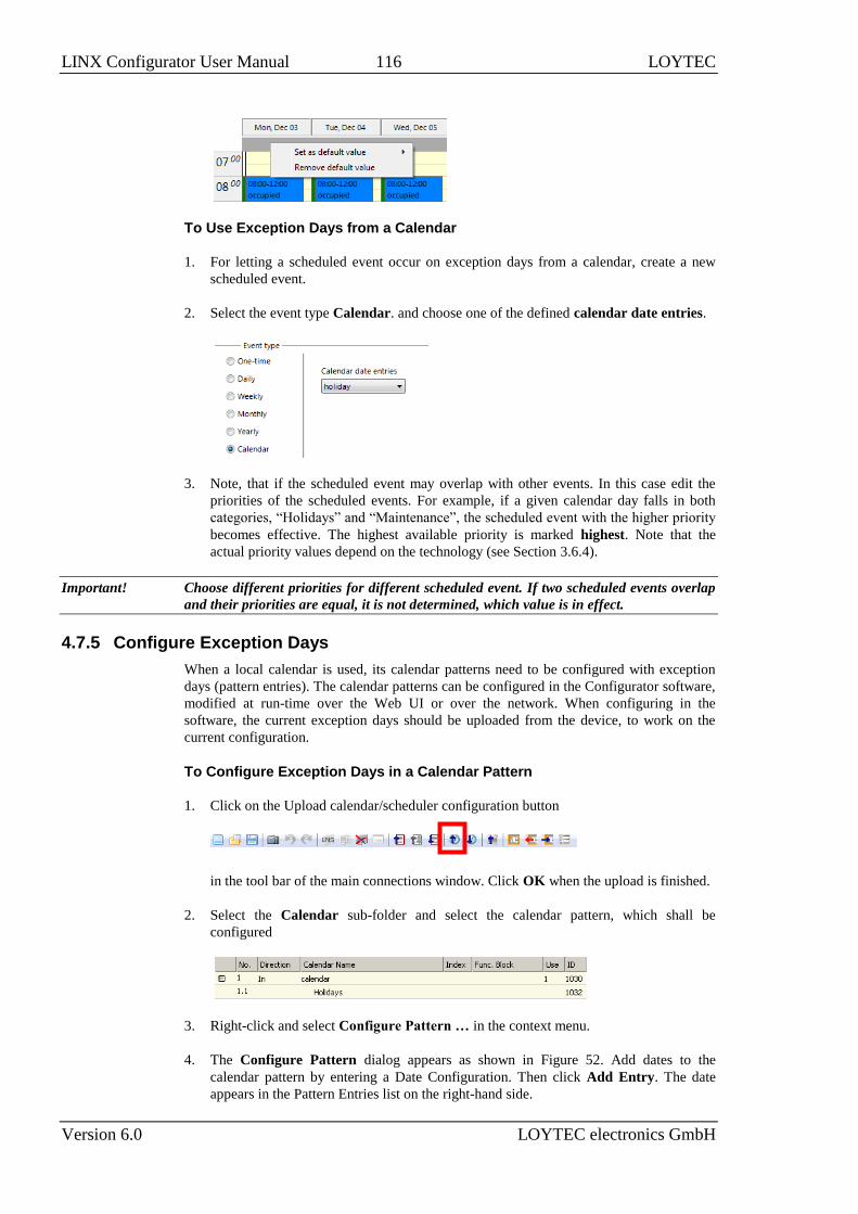
LINX Configurator User Manual 116 LOYTEC
Version 6.0 LOYTEC electronics GmbH
To Use Exception Days from a Calendar
1. For letting a scheduled event occur on exception days from a calendar, create a new
scheduled event.
2. Select the event type Calendar. and choose one of the defined calendar date entries.
3. Note, that if the scheduled event may overlap with other events. In this case edit the
priorities of the scheduled events. For example, if a given calendar day falls in both
categories, “Holidays” and “Maintenance”, the scheduled event with the higher priority
becomes effective. The highest available priority is marked highest. Note that the
actual priority values depend on the technology (see Section 3.6.4).
Important! Choose different priorities for different scheduled event. If two scheduled events overlap
and their priorities are equal, it is not determined, which value is in effect.
4.7.5 Configure Exception Days
When a local calendar is used, its calendar patterns need to be configured with exception
days (pattern entries). The calendar patterns can be configured in the Configurator software,
modified at run-time over the Web UI or over the network. When configuring in the
software, the current exception days should be uploaded from the device, to work on the
current configuration.
To Configure Exception Days in a Calendar Pattern
1. Click on the Upload calendar/scheduler configuration button
in the tool bar of the main connections window. Click OK when the upload is finished.
2. Select the Calendar sub-folder and select the calendar pattern, which shall be
configured
3. Right-click and select Configure Pattern … in the context menu.
4. The Configure Pattern dialog appears as shown in Figure 52. Add dates to the
calendar pattern by entering a Date Configuration. Then click Add Entry. The date
appears in the Pattern Entries list on the right-hand side.

LINX Configurator User Manual 117 LOYTEC
Version 6.0 LOYTEC electronics GmbH
5. Edit an exception by selecting the pattern entry in the Pattern Entries list. Then
modify the date configuration in the Date Configuration group box.
Figure 52: Configure Calendar Pattern Dialog.
6. Click Save Changes when all exception days have been entered.
Tip! If not sure, how a date configuration affects the calendar days, click on a pattern in the
Pattern Entries list and the affected days will be highlighted in the Preview.
4.7.6 Configure Control Data Points
A scheduler object can be configured to use special control data points. These data points
can control the scheduler and expose additional state information of the scheduler on the
network. The following control data points are available:
Scheduler Enable/Disable Datapoint: This data point can be configured, which
enables or disables the scheduler depending on its Boolean value.
Enable/Disable Feedback Datapoint: This data point is updated with the current
enabled state of the scheduler. This also reflects and an enable from the network.
Scheduled Preset Name: This data point can be attached to be updated with the name
of the currently active preset. Only string data points can be attached.
To Configure Control Data Points
1. Open the Configure Schedule dialog to configure daily schedules as described in
Section 4.7.3.
2. Go to the Scheduled Datapoints tab.

LINX Configurator User Manual 118 LOYTEC
Version 6.0 LOYTEC electronics GmbH
3. In the Control Datapoints group box, click the button to add the desired control
data point. A data point selection dialog opens.
4. Select a matching data point and click OK. For the preset name a string data point must
be selected.
5. To remove an undesired control data point, click on the Remove button.
4.7.7 Using the SNVT_tod_event
On LOYTEC devices with the CEA-709 technology the SNVT_tod_event can be used in a
schedule for implementing the next-state feature. The parts of this network variable contain:
Current state: This is the currently scheduled occupancy state.
Next state: This is the next, future occupancy state in the schedule.
Time to next state: This part reflects the time in minutes until the next state becomes
active.
To Use a SNVT_tod_event
1. Create a SNVT_tod_event in the data point configuration.
2. Add the SNVT_tod_event to the scheduled data points of a scheduler as described in
Section 4.7.3.
3. All three parts of the SNVT_tod_event are scheduled.
4.7.8 Using the Local Scheduler
Once the setup of the local scheduler is done, it is basically operational. It will immediately
start working based on the configuration data downloaded through the configuration
software. You can verify the daily schedules and values of scheduled data points on the
Web interface. The local schedule can be altered over the Web UI or over the network using
the underlying networking protocol.
4.8 Local Alarming
4.8.1 Create an Alarm Server
To generate local alarms, an alarm server needs to be created at first. The local alarm
sources will report alarms to that alarm server. The alarm server is the interface to access
local alarms. This can be done over the network or the Web UI.
To Create an Alarm Server
1. Under the device folder, select the Alarm sub-folder to create a generic alarm server.
For a technology alarm server, select the Alarm sub-folder of the respective port.

LINX Configurator User Manual 119 LOYTEC
Version 6.0 LOYTEC electronics GmbH
2. Right-click in the data point list view and select New Alarm Server ….
3. In the Create New Alarm Server dialog box (as shown in Figure 53) enter Name and
Description of the alarm server.
Figure 53: Create New Alarm Server dialog box.
4. For alarm transitions you may define, which require acknowledgement and at which
priority they are reported.
5. You may attach data points for storing alarm counters. These will be linked using the
respective property relations (see Section 3.1.12).
6. When you create a generic alarm server, you may add technology alarm servers, that
shall be reported to. Click on and choose one alarm server of each technology. If
they don’t exist, you need to create them under the technology port folders.
7. Click Create. The alarm server appears now in the data point list view.
8. For a BACnet technology alarm server, edit the instance number of the Notification
Class object to your needs.

LINX Configurator User Manual 120 LOYTEC
Version 6.0 LOYTEC electronics GmbH
4.8.2 Create an Alarm Condition
To generate alarms from data points, intrinsic reporting is used. For each data point an
alarm condition must be defined. This condition employs an intrinsic algorithm to generate
alarms based on the data point’s value or by evaluating a feedback value. Depending on the
data point type (analog, binary, multi-state), different conditions are defined. The alarm is
reported to the attached alarm server.
To Create an Intrinsic Alarm Condition
1. Select a data point.
2. Right-click and select Create Alarm Condition… from the context menu.
3. For the alarm condition edit the following definitions, which apply to all condition
types as shown in Figure 54. Select the Alarm Server which the alarm shall be
reported to. Typically, you will choose a generic alarm server.
4. Enter an Alarm Message. This is shown when the alarm becomes active. You may add
variable placeholders to this message by selecting one from the drop-down box add
var on the right-hand side. Enter a Clear Message. This is shown when the alarm
clears. For analog alarms, the alarm message is split into a low-limit (LO) message and
a high-limit (HI) message, respectively.
5. Check the option Enable Fault Alarms, if fault conditions (offline, unreliable) shall
generate fault alarms. If enabled, enter a Fault Message, which is displayed along with
the fault alarm when it occurs.
6. Optionally, enter a Time Delay, for which the condition must persist before the alarm
becomes active or is cleared again. The delay is entered in seconds.
7. By clicking you may attach a data point, which is evaluated for enabling the alarm.
This can also be done by editing the property relation ‘enableAlarm’ (see Section
4.2.8). Detach the data point by clicking .
8. Choose the option value is different from to define a feedback alarm. In this case the
setpoint value of the alarmed data point is compared against the feedback value. A
feedback data point can be attached for this purpose. This can also be done by editing
the property relation ‘feedbackRelation’ (see Section 4.2.8).
9. Choose the option value has condition to define a value alarm. In this case the data
point value is compared against the condition. Edit the condition in the box below this
option.
Figure 54: Common settings for an alarm condition.
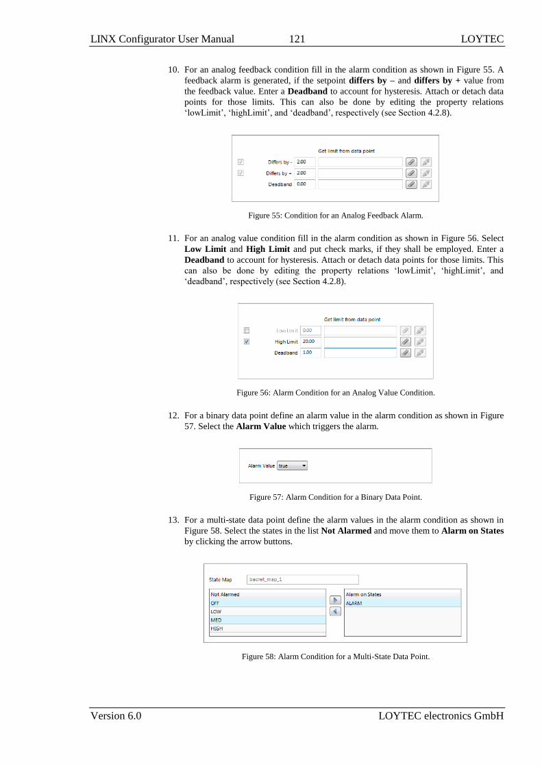
LINX Configurator User Manual 121 LOYTEC
Version 6.0 LOYTEC electronics GmbH
10. For an analog feedback condition fill in the alarm condition as shown in Figure 55. A
feedback alarm is generated, if the setpoint differs by – and differs by + value from
the feedback value. Enter a Deadband to account for hysteresis. Attach or detach data
points for those limits. This can also be done by editing the property relations
‘lowLimit’, ‘highLimit’, and ‘deadband’, respectively (see Section 4.2.8).
Figure 55: Condition for an Analog Feedback Alarm.
11. For an analog value condition fill in the alarm condition as shown in Figure 56. Select
Low Limit and High Limit and put check marks, if they shall be employed. Enter a
Deadband to account for hysteresis. Attach or detach data points for those limits. This
can also be done by editing the property relations ‘lowLimit’, ‘highLimit’, and
‘deadband’, respectively (see Section 4.2.8).
Figure 56: Alarm Condition for an Analog Value Condition.
12. For a binary data point define an alarm value in the alarm condition as shown in Figure
57. Select the Alarm Value which triggers the alarm.
Figure 57: Alarm Condition for a Binary Data Point.
13. For a multi-state data point define the alarm values in the alarm condition as shown in
Figure 58. Select the states in the list Not Alarmed and move them to Alarm on States
by clicking the arrow buttons.
Figure 58: Alarm Condition for a Multi-State Data Point.

LINX Configurator User Manual 122 LOYTEC
Version 6.0 LOYTEC electronics GmbH
14. Click on Create. In the alarm column, the alarm sign will be added for those data
points that have an alarm condition. If a sub-data point has been alarmed, the top-level
data point will indicate this with the sign .
4.8.3 Deliver Alarms via E-mail
Updates in the alarm summary of an alarm object can be used as a trigger to send e-mail.
For setting up e-mails, the account information has to be configured on the device, e.g., on
the Web UI (see Section “E-Mail” of the LOYTEC Device User Manual [1]). Then an e-
mail template can be created and the alarm point attached as a trigger. The e-mail template
can be configured to contain certain alarm information in the text or subject field.
To Create an E-mail Template for Alarms
1. Create or configure an e-mail template as described in Section 4.6.1.
2. Change to the Mail Triggers tab.
3. Click the Add… button and select an alarm data point.
4. In the Mail Triggers list select the added trigger data point.
5. In the Manage Trigger Conditions list put a check mark on alarm conditions that shall
invoke the transmission of the e-mail.
6. Change to the Common E-Mail Properties tab.
7. Add the alarm data point as a data source as described in Section 4.6.1.
8. Choose the desired alarm information from the fields in the drop-down Selected Data
Source Value and paste a place holder into the e-mail text or subject field.
4.8.4 Create an Alarm Log
The alarm objects on the device contain an alarm summary (live list) of currently active and
acknowledge-pending alarms. As soon as an alarm becomes inactive and has been
acknowledged, it disappears from the alarm summary. To store a historical log of alarm
transitions an alarm log needs to be created.

LINX Configurator User Manual 123 LOYTEC
Version 6.0 LOYTEC electronics GmbH
An alarm log can log transitions of one or more alarm objects. Its size is configurable. The
alarm log can be operated as ring or as linear buffer. When operated as ring buffer, the
oldest alarm log records are overwritten by new alarm transitions, as soon as its size limit is
reached. When operated as linear buffer no more alarms are logged once the log is full.
To Create an Alarm Log
1. Under the Global Objects folder, select the Alarm Log Object Configuration sub-
folder.
2. In the data point list right-click and select New Alarm Log … from the context menu.
3. In the New Alarm Log dialog enter a Name for the alarm log. Optionally enter a
Description.
4. Enter a Log Size, which defines how many transitions are resident in the alarm log.
5. Select the desired Fill Mode. The default is Ring Buffer, which lets the log overwrite
old records once it reaches its capacity. Select Linear Buffer, if recording shall be
stopped in this case. The user has to purge the log before it continues recording.
6. Define a percentage for Fill Level Notification, which can be used to trigger the
transmission of E-Mails.
7. Click on the button Add… on top of the Logged Alarm Objects list.
8. A data point selector dialog opens. Select one or more alarm objects that shall be
logged and click OK. The alarm objects appear in the list.
9. Click Create to create the alarm log object.
4.8.5 Multi-Edit Alarm Conditions
For editing a large number of alarm conditions, some multi-edit features are available to
assist in this task. On a multi-selection of data points, the user can execute two options from
the context menu:
Configure Alarm Conditions: Use this option from the context menu on a multi-
selection of data points. The alarm condition of all selected data points can be edited. If
all selected data points are of the same class (e.g., all analog data points) the alarm

LINX Configurator User Manual 124 LOYTEC
Version 6.0 LOYTEC electronics GmbH
condition can be fully specified. Note that these settings will be applied to all data
points. In alarm messages use variable place holders. For assigning different limit and
enable data points use the manage relations tab (see Section 4.2.8).
Configure Alarm Messages: Use this option from the context menu for editing alarm
messages (alarm, clear, fault) for all data points in the selection. A dialog with a
spreadsheet view appears as shown in Figure 59. Edit the messages directly in the
spreadsheet. Alternatively, click on the export button to export the spreadsheet as a
CSV file for editing in Excel. Import a CSV file with alarm messages in the menu
Tools Import alarm messages.
Note: Use the feature to include data points from sub-folders and filter expressions to expand the
ability to perform a multi-select.
Figure 59: Spreadsheet for multi-edit of alarm messages.
4.9 Local Trending
4.9.1 Create a Local Trend
The value of a data point can be logged over time. This is referred to as trend data. To
generate trend data a trend object has to be created. The trend data is stored in a data logger
file. This file can be downloaded via FTP in binary or CSV format (see the LOYTEC
Device User Manual [1]).
Trend objects can generate trend logs for single and multiple data points and can be
operated in one of the following modes:
Interval Mode: In this mode a snapshot of all trended data points is logged into the
data logger file. Aligned log intervals can be configured.
COV Mode: In this mode, each of the trended data points is logged separately, if and
only if its value changes. For analog data points, a specific COV increment can be
configured in the data point configuration properties of the trended data point.
Trigger Mode: In this mode a snapshot of all trended data points is logged each time a
trigger condition fires. The trigger condition is applied to a trigger data point.
To Create a Trend Object
1. Select the Trend folder of the device.
2. In the data point list right-click and select New Trend … from the context menu.

LINX Configurator User Manual 125 LOYTEC
Version 6.0 LOYTEC electronics GmbH
3. In the Create New Trend Object dialog (shown in Figure 60) enter a name and
optionally a description for the trend log object.
Figure 60: Basic Trend Object Configuration.
4. Select the desired Trend Mode.
5. On devices with SD cards, select External trend storage, if this trend log shall be
backed up to an SD card. If doing so, also set the Fill Level Notification, which
triggers when a backup is written to the external storage.
6. Select the Log Size. The display in the dialog will adapt the estimations for needed data
logger file size in KB and duration of the trend log. Alternatively, for interval trends,
the estimated log duration and log interval can be edited.
7. In the interval trend mode the Align interval option can be activated. Depending on the
selected interval, the beginning of the interval is aligned to the wall time (e.g. every 15
minutes aligned to the top of the hour). An additional offset in seconds to that
alignment can be specified (e.g. 5 seconds after those 15 minutes).
8. Select a Fill Level Notification percentage. This will decide at which fill-level trigger
will fire. A fill-level trigger can be used to trigger the transmission of an e-mail (see
Section 4.9.5) or a backup of log data to the SD card.
9. Click Save changes to store the basic configuration of the trend object. The new trend
log object appears in the data point list of the Trend folder.
4.9.2 Configure Trended Data Points
When a local trend object has been created, it needs to be configured, which data points it
shall log. This is done by attaching data points to the trend object. Only simple data points
can be attached for trending, i.e., of class analog, binary, or multi-state. Generic trend logs
also support string data points. For trend log objects in the BACnet technology, single data
points can be attached only.
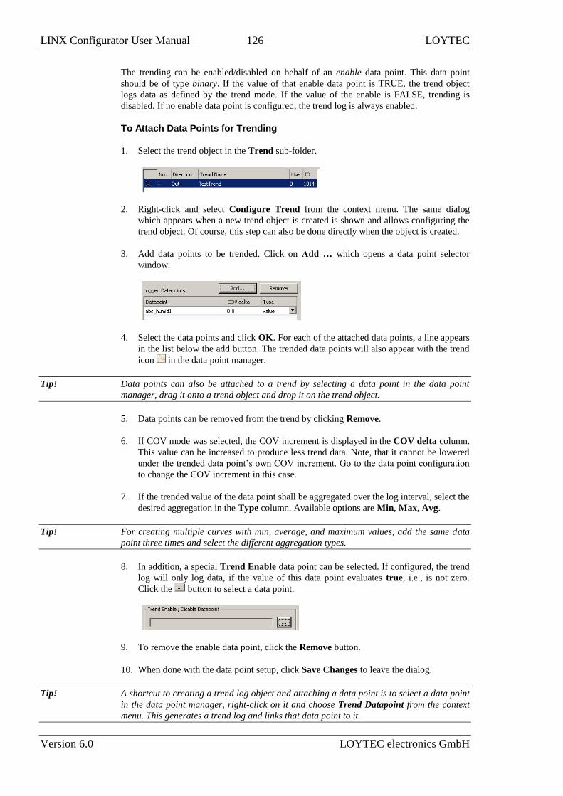
LINX Configurator User Manual 126 LOYTEC
Version 6.0 LOYTEC electronics GmbH
The trending can be enabled/disabled on behalf of an enable data point. This data point
should be of type binary. If the value of that enable data point is TRUE, the trend object
logs data as defined by the trend mode. If the value of the enable is FALSE, trending is
disabled. If no enable data point is configured, the trend log is always enabled.
To Attach Data Points for Trending
1. Select the trend object in the Trend sub-folder.
2. Right-click and select Configure Trend from the context menu. The same dialog
which appears when a new trend object is created is shown and allows configuring the
trend object. Of course, this step can also be done directly when the object is created.
3. Add data points to be trended. Click on Add … which opens a data point selector
window.
4. Select the data points and click OK. For each of the attached data points, a line appears
in the list below the add button. The trended data points will also appear with the trend
icon in the data point manager.
Tip! Data points can also be attached to a trend by selecting a data point in the data point
manager, drag it onto a trend object and drop it on the trend object.
5. Data points can be removed from the trend by clicking Remove.
6. If COV mode was selected, the COV increment is displayed in the COV delta column.
This value can be increased to produce less trend data. Note, that it cannot be lowered
under the trended data point’s own COV increment. Go to the data point configuration
to change the COV increment in this case.
7. If the trended value of the data point shall be aggregated over the log interval, select the
desired aggregation in the Type column. Available options are Min, Max, Avg.
Tip! For creating multiple curves with min, average, and maximum values, add the same data
point three times and select the different aggregation types.
8. In addition, a special Trend Enable data point can be selected. If configured, the trend
log will only log data, if the value of this data point evaluates true, i.e., is not zero.
Click the button to select a data point.
9. To remove the enable data point, click the Remove button.
10. When done with the data point setup, click Save Changes to leave the dialog.
Tip! A shortcut to creating a trend log object and attaching a data point is to select a data point
in the data point manager, right-click on it and choose Trend Datapoint from the context
menu. This generates a trend log and links that data point to it.

LINX Configurator User Manual 127 LOYTEC
Version 6.0 LOYTEC electronics GmbH
4.9.3 Trend Triggers
Local trend objects in CEA-709 can be operated in trigger mode. In this mode, one or more
trigger data points cause the generation of a snapshot containing the values of the trended
data points at the time instant the trigger is activated. For a trend object, one or more trigger
conditions can be defined. Depending on the trigger data point type, the trigger conditions
can be refined.
Note, that the behavior of the trigger data point is influenced by the COV properties of the
data point. If the Only notify on COV property is checked, the data point triggers only if its
value changes to the value of the trigger condition. If that property is not checked, the data
point triggers on every write with a value that matches the trigger condition.
To Configure Trigger Data Points for Trending
1. Select the trend object in the Trend sub-folder.
2. Right-click and select Configure Trend from the context menu.
3. Change to the Triggers tab.
Note: Of course, you can also change directly to the Triggers tab when creating a trend object.
4. Click the Add… button. A data point selection dialog opens.
5. Select one or more data points and click OK.
6. The triggers appear now in the Trend Triggers list.
7. In the Manage Trigger Conditions you can refine the trigger condition depending on
the trigger data point class.
8. When done with the data point setup, click Save Changes to leave the dialog.
4.9.4 Download Trend Data in CSV Format
Trend logs can be downloaded from the device via FTP in CSV format (see LOYTEC
Device User Manual [1]). The CSV contents are generated on-the-fly from the internal
binary storage when accessing the file. Each trend log point has one CSV file. The files are
located in
/data/trend/TrendLogName_UID.csv
Where TrendLogName is the data point name of the trend (Trend Name). The UID is the
unique ID of the trend log object. The UID can be obtained from the ID column in the data
point list of trend log data points as shown in Figure 61. This would result in the trend CSV
file ‘/data/trend/out_temp_107C.csv’.
Figure 61: UID of data points.

LINX Configurator User Manual 128 LOYTEC
Version 6.0 LOYTEC electronics GmbH
Because the contents are generated on-the-fly, the file size in the FTP client will appear as 0
Bytes. The decimal point and CSV column separator can be configured in the system
configuration of the Web UI. Note, that for a comma “,” as the separator, the decimal point
is a point. This is useful for English/U.S. applications. For countries that use the comma as
the decimal point, select the semicolon as the CSV separator.
4.9.5 Deliver Trend Data via E-mail
Trend logs can be downloaded from the device via FTP. This requires an active action by
the user. Alternatively, trend data can be sent as an e-mail attachment. For doing that, an
e-mail template has to be setup for the trend log to be transmitted. The fill-level condition in
the trend object can be used as a trigger to send an e-mail with the trend’s data logger CSV
file as an attachment.
For setting up e-mails, the account information has to be configured on the device, e.g., on
the Web UI. Then an e-mail template can be created and the trend object attached as a
trigger.
To Create an E-mail Template for Trends
1. Create or configure an e-mail template as described in Section 4.6.1.
2. Change to the Mail Triggers tab.
3. Click the Add… button and select a trend object.
4. In the Mail Triggers list, the added trigger data point appears with the Fill Level
condition.
5. Change to the Attachments tab.
6. Select the trend log CSV file of the trend object in the Attach File drop-down box and
click Add.
Note: ZIP versions of the CSV files are also available. Select those to save transmission
bandwidth and mailbox space.
7. Click OK to complete the e-mail template configuration.
4.9.6 Technology Trends
In the BACnet technology, trend logs can be exposed on the BACnet port via special
BACnet Trend Log objects. To create a technology trend select the port folder (e.g.,
BACnet Port) and then the Trend folder underneath. Follow the same instructions as
described in Section 4.9.1. Please note, that certain restrictions apply to BACnet trends (see
Section 3.7.4).

LINX Configurator User Manual 129 LOYTEC
Version 6.0 LOYTEC electronics GmbH
4.10 Remote AST Objects
4.10.1 Remote Scheduler and Calendar
Adding remote access to the configuration of a scheduler and calendar, which is located on
another device, is done by creating remote scheduler and calendar objects. These objects
can be created from data obtained by a network scan. With a CEA-709 device an LNS scan
can also be used. Remote scheduler and calendars are supported by CEA-709 and BACnet
technologies.
To Create a Remote Scheduler
1. Execute a network scan, as described earlier in this document. The scan folder is filled
with available schedulers.
2. From the data points in the import folder, select the scheduler objects you are interested
in and click the Use on Device speed button. This creates suitable remote
schedulers and the corresponding calendar objects in the Remote Devices folder.
3. Adjust the basic settings for the newly created objects, such as the object name and
description. The object name will be used as the name for the scheduler, as seen on the
Web UI.
Note: Due to the static input NV, which is required for a remote CEA-709 scheduler object,
adding remote scheduler points will change the static interface of the device.
The new static input NV representing the remote calendar on the local device (this NV is
normally called nviCalLink) needs to be bound to the output NV called nvoCalLink located
in the Calendar functional block of the remote device and the new static nviSchedLink NVs
which were created for each remote scheduler point need to be bound to the respective
nvoSchedLink variable located in the Scheduler functional block of the remote device. The
binding between the nvoSchedLink variable on the remote device to the nviSchedLink
variable on the local device defines which of the scheduler data points on the local device
connect to which scheduler unit on the remote device. All required information is
transmitted over the link NVs, so it is possible to later change the binding to any other
remote scheduler without rescanning the network.
Note: If connected via LNS, the bindings to the nvoCalLink and nvoSchedLink NVs are made
automatically by the configuration software in the download process.
4.10.2 Alarm Clients
Accessing alarm server objects on remote devices is done by creating remote alarm data
points. These points may be created from data obtained by a network scan. The local device
is configured as an alarm client and subscribes to alarm updates from the remote alarm
server. The alarm client can also be used to acknowledge alarms on the remote alarm server.
Any updates are synchronized back to the alarm client. Remote alarm servers are supported
by CEA-709 and BACnet technologies.

LINX Configurator User Manual 130 LOYTEC
Version 6.0 LOYTEC electronics GmbH
To Create an Alarm Client
1. Execute a network scan, as described earlier in this document. The scan folder is filled
with available remote alarm servers.
2. From the points in the import folder, select the alarm server points you are interested in
and click the Use on Device speed button. This creates the corresponding alarm
client points in your project.
3. In the CEA-709 technology select the new alarm client point and adjust the name of the
local NV (default name is nviAlarm_2). This NV is located in the Clients functional
block.
4. In the CEA 709 technology a static NV is created to receive information from the
remote device about changes to the scheduler configuration, so that the local device
does not need to poll the remote device. Set a name for this NV (default is
nviSchedLink<number>) and assign it to a suitable function block.
Note: Due to the static input NV which is required for a CEA-709 alarm client point, adding
alarm clients will change the static interface of the device.
The new static input NVs representing the alarm clients on the local device need to be
bound to the alarm outputs of the remote device. A CEA-709 device normally delivers
alarms through an output NV of type SNVT_alarm_2 located in the node object of the
device, therefore the new input NV on the local device must be bound to the alarm output
NV of the remote devices node object. All required information is transmitted over the
alarm input NV, so it is possible to later bind the alarm client to any other alarm server
without rescanning the network.
Note: If connected via LNS, the binding to the nvoAlarm2 NV is made automatically by the
configuration software in the download process.
4.10.3 Remote Trend Logs
A remote trend log provides access to trend log data, which is actually generated and stored
on another device. The remote trend log can load trend data from that device and supply it
to L-WEB or a CSV file. Please note, that currently only the BACnet technology supports
remote trend logs.
To Create a Remote Trend Log
1. Execute a network scan, as described earlier in this document. The scan folder is filled
with available trend logs.

LINX Configurator User Manual 131 LOYTEC
Version 6.0 LOYTEC electronics GmbH
2. From the data points in the import folder, select the trend log objects you are interested
in and click the Use on Device speed button. This creates suitable remote trend
logs in the Remote Devices folder.
4.11 Math Objects
4.11.1 Create a Math Object
Math objects are advanced application objects that can execute mathematical operations on
data points. A math object takes a number of input data points (variables v1, v2, …, vn) and
calculates a result value according to a specified formula. When configuring a math object,
the input data points, output data points and the formula must be configured by the user.
Input data points can be configured with a change-of-value condition, to trigger the math
calculation only if the value changes more than a certain delta.
To Create a Math Object
1. Under the Global Objects folder, select the Math Object sub-folder.
2. Right-click and select New Math Object … from the context menu.
3. In the Create New Math Object dialog, enter a name and optionally a description for
the math object.
4. Attach input data points by clicking the Add Input DP button.
5. In the data point selector dialog, select the input data points and click OK. The data
points appear as v1, v2, etc.
Tip! A math object can also be created by multi-selecting data points in the data point manager
and right-clicking on them. Then choose Create Math Object … from the context menu.
This opens the dialog and attaches the selected data points as input variables.
6. If the data point shall trigger the math calculation only after a certain change-of-value,
enter a value into the COV delta column. If the data point shall never trigger the math
calculation, de-select the Triggers Calculation check box.

LINX Configurator User Manual 132 LOYTEC
Version 6.0 LOYTEC electronics GmbH
7. Select the input data point and click Add Variable to push the variable on the
evaluation stack.
8. Select a function to be applied on the variables and click the Add Function button.
9. Te resulting formula is displayed at the bottom of the dialog. Alternatively, the formula
can be entered there.
Note: When the formula entered at the bottom is still incomplete and does not yield a meaningful
command sequence, the list showing the RPN equivalent will be empty. This allows the user
to immediately see if the current input is valid or not.
10. Add output data points by clicking the Add Output DP button.
11. In the data point selector dialog select the output data points and click OK.
12. To create the math object click Create.
4.11.2 Editing a Math Object
Math objects can be edited once created. The formula can be changed, new variables added,
or additional output data points added.
To Edit a Math Object
1. Under the Global Objects folder, select the Math Object sub-folder.
2. Select the math object in the data point list.
3. Right-click and select Configure Math Object … from the context menu.
4. Edit the math object as described in Section 4.11.1.

LINX Configurator User Manual 133 LOYTEC
Version 6.0 LOYTEC electronics GmbH
5. To replace an input data point by another input data point without re-writing the entire
formula, click the Replace Input DP … button. This opens a data point selector
dialog. Select the replacement data point there.
6. To detach an input data point, click the Detach Input DP button. This leaves the
respective variable slot empty.
7. To finalize the edit click on Save Changes.
4.12 Historic Filters
4.12.1 Create Historic Filters
Historic filters are used to work with historic values of a base data point. These historic
values are derived by defining historic filter functions. An historic filter template is a
collection of such filter functions and can be assigned to any analog, binary, or multi-state
base data point. For more general information on historic filters refer to Section 3.4.6.
To Create Historic Filters
1. Select one or more data points that shall serve as the base data points.
2. Right-click and select the Configure Historic Filters … item in the context menu. As
an alternative, click on of the Historic Filter data point property.
3. The dialog Select Historic Filter opens. Click on to create a new one.
4. In the Create Historic Filter dialog enter a name and optionally a description.
5. To add a new filter function to the list click on the add button . Enter a filter entry
Name and choose the desired period Type. The name will appear with the historic
filter relation and helps identifying it. Depending on the type define the arguments Day
and Time. Select how many samples ago the filter goes back. The most current sample
is ‘0’, the previous one is ‘1’.
6. To duplicate an entry click on the duplicate button . On the duplicate modify the
settings accordingly.
7. For getting the difference of an historic value to the current value check the box Delta
to current.

LINX Configurator User Manual 134 LOYTEC
Version 6.0 LOYTEC electronics GmbH
8. Click on Save Changes and select the created filter template. For each filter entry
defined, a historicFilter property relation is created under the base data point(s).
4.12.2 Managing Historic Filter Resources
Historic filters are stored as template types in the project resources. The Configurator
provides a resource manager, that can be used to view, edit, import and export historic filter
resources. When modifying an historic filter template, all instances that use it are updated.
Select the menu Tools Manage Historic Filters … to open the resource manager dialog.
Select a filter type and click the edit button for modifying it. Use the plus button to add
new filters and the minus button to delete selected filters. Click the duplicate button to
create a duplicate of the selected filter. Click the import button to load historic filters
from disk. When importing, filter definitions of the same name are overwritten. Click the
export button to store current filters to disk.
4.13 Automated Data Point Handling
4.13.1 Data Point Modification by Export/Import
The Configurator provides a data point export/import interface, which can be used to
perform batch edits in an external tool, such as Excel. The data point export feature allows
exporting a CSV file of a data point selection (multi-select or by folder selection), which
contains a set of data point properties in its columns. The export also allows a flexible
selection of exported properties. A matching import will then take the property values from
the CSV file and paste them onto the existing data points.
Data points are identified by a key column, which can be the data point’s unique ID (UID)
or full path (IdPath). If a matching data point is found for a line in the CSV file, the
columns are applied to its properties. If none of the key columns are present in an imported
CSV file, data points are created using the specified properties. For a batch edit, the key
columns have to be left in the CSV file, and only columns should be modified. For a full
reference of the CSV file format refer to Section 15.1.
To Export a Data Point CSV
1. Select one or more data points, or select one or more folders.
2. Right-click and choose Export Data Point CSV … from the context menu.
3. The Data Point CSV Export dialog opens as shown in Figure 62.

LINX Configurator User Manual 135 LOYTEC
Version 6.0 LOYTEC electronics GmbH
Figure 62: Data point CSV export dialog.
4. Select a pre-defined set of data point properties that shall be exported as columns of the
CSV file.
5. If this set does not reflect the desired properties, edit the property set. Select one or
more properties in the Property list and click on minus to remove them from the list, or
click on plus to add more properties.
6. When finished modifying the property set, click on the save button to store the
property set for later use. To open a stored property set, click on the load button .
This property set is then available in the drop-down list.
7. Choose an encoding, e.g. ‘UTF-8’.
8. Select Write values of child data points if the exported CSV shall also contain all
child data points of structures.
9. Finally click the button Write CSV to generate the CSV file. This file is now ready to
be edited in an external tool.
To Modify Data Point Properties from a CSV
1. Select a data point folder.
2. Right-click and choose Import Data Point CSV … from the context menu.
3. Choose a CSV file to be imported. The Configurator opens that file and applies the
properties to the existing data points. When finished a report is shown as depicted in
Figure 63.
Figure 63: Report on an imported data point CSV.

LINX Configurator User Manual 136 LOYTEC
Version 6.0 LOYTEC electronics GmbH
4.13.2 Data Point Creation from CSV
The data point CSV format allows for creating data points from information in the CSV
columns. By omitting the identification columns (UID, IdPath) from the data point CSV the
create mode is active when importing the data point CSV. Data points are then created
relative to the folder on which the import was started. The ‘Path’ column specifies that
relative path and the ‘Name’ column defines the data point name. For a full specification of
the data point CSV format refer to Section 15.1.
To create data points from the CSV, remove the key columns from the exported CSV file or
export the CSV without these columns. Then follow the import steps of Section 4.13.1. Data
points from a certain #target section are filtered, if the selected source path does not match
the specified target technology. When importing from the device folder, all technologies are
imported, respectively.
4.13.3 Data Point Templates
The Configurator provides an import interface to automatically create a data point
configuration from a list of data point templates. This interface can be used by an external
tool, which generates such a list from its own project planning data.
Creating data points from data point template works like copy/paste of data points from an
existing configuration to a new one. The “copied” data point is just stored in a data point
template file (.dptmpl), which can be later “pasted”. For a given set of frequently used data
points of a given technology, the user can build a library of such template files.
Data point templates include the following properties of their original data point:
Generic and technology-specific properties,
Sub-data points of structures,
Property relations (without referenced objects),
Favorites (without referenced objects),
Alarm conditions (including required alarm servers).
To Create a Data Point Template
1. Select an existing data point in the data point list.
2. Right-click and select Create Data Point Template … from the context menu.
3. Enter a file name and store the ‘.dptmpl’ file.
To Apply a Data Point Template
1. Select one or more data points in the data point list.
2. Right-click and select Apply Data Point Template … from the context menu.
3. Choose a ‘.dptmpl’ file. This will re-model the data points to the selected template.
4.13.4 Creation from Data Point Template CSV
In order to create a batch of data points from those template files, a list can be specified in a
data point template CSV file (.dpcsv). For each line in this CSV file a data point will be
created under the specified path and name according to a data point template file.
Optionally, the description, PLC and OPC settings of the data point template can be

LINX Configurator User Manual 137 LOYTEC
Version 6.0 LOYTEC electronics GmbH
overridden by the CSV file. The format of the CSV file is specified in Section 15.1 .An
example CSV ‘dp_template.csv’ file can be found in the Configurator install directory under
‘examples\Data Point Templates’.
To Create Data Points from a Template CSV File
1. Create a data point template CSV file. An example is shown in Figure 40. The
referenced ‘.dptmpl’ files must be located in the same directory as the CSV file. The
path to the data point must be specified using the dot ‘.’ as the folder separator.
Figure 64: Example Data Point Template CSV File.
2. Select the menu Tools Import Data Point Template CSV … and choose the
created CSV file.
3. The temperature registers in the example are specified as trended. If the device model
supports different trend technologies, the import will prompt to choose one.
4. The import creates two temperature analog registers and two binary registers with
alarm conditions. The data point templates refer to an alarm server, which is also
created, if none exists with the same name.
4.14 Using L-WEB
The L-WEB is a Web-based visualization software that comes free with the device. It uses
the standard Web technologies to visualize and control data provided by one or more
LOYTEC devices on a Windows PC.
The L-WEB software uses the standardized OPC XML-DA Web service to communicate
between L-WEB and remote LOYTEC devices, which makes it extremely firewall-friendly
and easy to setup.
The graphical design of the L-WEB user interface consists of pages, which can simply be
created by using the L-VIS/L-WEB Configurator software without any know-how in
HTML, Java, etc. Dynamic information is shown in the form of numeric values, text,
changing icons, bar graphs, trend logs, alarm and event lists, or schedule controls.
The complete set of automation functions of the data server is fully supported by L-WEB.
The automation services are residing in the embedded devices and are distributed over the
network to build up a dependable system with L-WEB only accessing these services.
Furthermore, any kind of calculations, data point connections, etc., are implemented on the
embedded Automation Server, which makes the application on the Automation Server
completely independent from the connection to the L-WEB application.
Starting from the data point configuration, the user can create an L-WEB project. The
L-WEB project contains the data point configuration of the Web service interface and a

LINX Configurator User Manual 138 LOYTEC
Version 6.0 LOYTEC electronics GmbH
graphical design for the L-WEB user interface. For more information on creating graphical
designs using the L-VIS/L-WEB Configurator software refer to the L-VIS User Manual [6].
4.14.1 Create a new L-WEB Project
The Configurator provides the data point configuration, which is downloaded to the device.
On top of that configuration, an L-WEB design can be created for visualization.
To Create an L-WEB Project
1. Start the Configurator software and change to the L-WEB Projects tab.
2. The L-WEB project tab appears as in Figure 65.
Figure 65: L-WEB Projects Tab.
3. Click on Add New …
4. Enter a new Project Name.
5. Click on Create. The new project appears in the projects list.

LINX Configurator User Manual 139 LOYTEC
Version 6.0 LOYTEC electronics GmbH
4.14.2 Start a Graphical L-WEB Design
The L-WEB graphical design tool is started from within the L-WEB projects tab. The
graphical design for the L-WEB project is created in the L-VIS design tool (L-VIS/L-WEB
Configurator). The data point configuration created in the Configurator project is available
for the L-WEB project and its graphical design.
To Start a Graphical Design
1. Select the L-WEB Projects tab.
2. Select an L-WEB project.
3. Click Edit.
4. This opens the L-VIS graphical design tool. Complete the graphical design in the tool
and click the Write Project to Device speed button
5. The graphical design is now part of the project.
Note: If the Configurator had been connected to the device, the graphical design would have
been added to the device in the same step.
4.14.3 Organize L-WEB Projects
L-WEB projects can be organized within the L-INX configuration project. L-WEB projects
can be part of the configuration project and/or stored on the device. For instance, the
configuration project may contain a number of L-WEB projects, but for saving space on the
device, only one of them is downloaded on the device. The L-WEB projects tab provides a
number of tools to organize a set of L-WEB projects.
To Organize L-WEB Projects
1. Connect to the device as described in Section 4.4.1.
2. Select the L-WEB Projects tab.
3. Click Detect Projects on Device. This scans for all projects found on the device.
Projects marked as a green Yes in the In LINX Project column are L-WEB projects,
which are part of the current L-INX configuration project. Projects marked as a green
Yes in the On Device column are L-WEB projects, which are also stored on the device.
A red No identifies the L-WEB project to be missing in the project or on the device,
respectively.

LINX Configurator User Manual 140 LOYTEC
Version 6.0 LOYTEC electronics GmbH
4. If you want to download an L-WEB project to the device, which is missing there, select
the project and click Download. After the download the project appears with a green
Yes in On Device.
5. If you want to remove a project from the device, click Remove in the LINX Device
box.
6. If you want to remove the project from the current L-INX project file, click Remove in
the L-WEB Projects on PC box.
7. If you want to export the L-WEB project into a separate L-WEB project file, click
Export… and select a file name in the file requestor dialog.
8. If you want to import an L-WEB project from a separate L-WEB project file, click
Import… and select the file in the file requestor dialog. The L-WEB project appears in
the project but not on the device.
4.15 I/Os
The L-IOB and LROC-40x models are equipped with local Inputs and Outputs to directly
connect to sensors and actuators. Additionally, a LIOB-48x/58x device can be extended
with the I/Os of one LIOB-45x/55x device. The following sections describe how to
configure these I/Os.
4.15.1 Configure I/Os
At first the I/Os have a default configuration. To adapt the I/Os to the specific needs in a
project they can be freely configured. Note that certain changes to the I/O configuration
must be committed before proceeding with other tasks. This can be done explicitly by
clicking Commit member changes . Otherwise, the user will be requested to commit by
the Configurator. Changes can be canceled by clicking Cancel member changes .
To Configure I/Os
1. For LIOB-18x models, select the Local I/O tab. For all other models, select the L-IOB
tab and then LIOB-LOCAL. For adding a LIOB-45x/55x device to a LIOB-48x/58x
model, select LIOB-IP in the L-IOB tab and use the Add Device(s) button .
2. The L-IOB tab displays the I/Os available on the device in the Inputs / Outputs list.

LINX Configurator User Manual 141 LOYTEC
Version 6.0 LOYTEC electronics GmbH
3. To adapt the I/O name, double-click the name in the Name column and edit it, e.g.,
‘RoomTemp’.
4. Select (or multi-select) an I/O in the Inputs/Outputs list and observe the Object
parameters list below. These parameters can be used to configure the I/O.
5. For example, change the SignalType of the input UI1 to ‘Resistance’.
6. Note that the object configuration properties may change when changing the signal type
or interpretation. For detailed information on available configuration properties and
their dependencies refer to Section 3.5. In this example you may now edit the
Interpretation to ‘NTC10K’, which will allow connecting an NTC temperature sensor
to the input.
7. Observe that the Object parameters table lists all I/O configuration properties and
also life values that can be exposed as L-IOB data points. These L-IOB data points in
turn can be exposed as OPC data points (LIOB-48x/58x) as well as input and/or output
data points in the logic program. Only the basic data points of each I/O (input, output,
feedback) are created by default. Using the checkboxes in the DP Create column of the
Objects parameters table, additional configuration properties and life values can be
exposed as L-IOB data points. Using the checkboxes in the OPC, PLC In, and PLC
Out columns, it is possible to select which of the created data points shall be exposed
as OPC data points, logic program input data points, and logic program output data
points.
8. For LIOB-58x devices, native BACnet objects (see Section 3.7.7) can be created using
the BACnet Object checkbox. For inputs with interpretation “Pulse Count”, it is
possible to choose between the BACnet Object Type “Analog Input” and
“Accumulator”. The corresponding data points will appear in the LIOB-58X / BACnet
Port / Datapoints folder of the Datapoints tab. The BACnet server object names and
descriptions will initially receive unique I/O names as described in Section 3.7.7. They
can be set to the current I/O names and descriptions by using the button Set BACnet
Names .
9. I/Os of the same hardware type can be copied using the Copy selected object and
Paste to selected object(s) buttons.
4.15.2 Manage I/O Configurations
I/O configurations can be managed by the user. E.g. a new template may be generated from
the I/O configuration, which can be re-used in other projects.
To Manage I/O Configurations
1. Select the L-IOB tab.
2. To export a new template for a L-IOB configuration click the Export device template
button . In the file save dialog, enter a new L-IOB template file name and store it.
This file can then be used in a different project using the Import Template button .

LINX Configurator User Manual 142 LOYTEC
Version 6.0 LOYTEC electronics GmbH
3. Existing configurations can be updated with new L-IOB templates by using the
Upgrade Template button . This can be used e.g. to migrate new functions which
were not yet available in earlier template versions. It is highly recommended to backup
the original project before upgrading templates. After upgrading the template, a log is
displayed, which shows all information about the upgrade process. Please carefully
review this log before using the updated configuration.
4. Another way of managing I/O configurations is using terminal configurations. A
terminal configuration can be created from an I/O object in the Inputs / Outputs list by
using the Export object to disc button next to the list. In this case, only the
configuration of this I/O is stored in an XML file. Terminal configurations can be
imported (to one or multiple I/Os of the same hardware type) by using the Import
object from disc button .
5. These terminal configurations can also be used to configure all I/Os of the L-IOB
device using a CSV file.
6. To setup translation tables for certain I/O interpretation modes, click the Edit
translation tables button .
Figure 66: L-IOB Translation Tables
7. You can add and delete tables using the buttons Add table and Delete table. The data
types for the xin and xout columns of the table can be setup in Type In and Type Out.
In the Translation table entries list, you can enter the xin and xout values. The
translation is done (with linear interpolation) from measured xin values to yout values
which are used for the L-IOB data points. Further, the table values can be exported and
imported (CSV files) with Import Values and Export Values. Entire tables (including
table name and type) can be exported and imported with Import Table and Export
Table. Tables of some standard temperature sensors are installed with the Configurator
in the subfolder “LIOB\tables”.

LINX Configurator User Manual 143 LOYTEC
Version 6.0 LOYTEC electronics GmbH
4.15.3 Using I/O Data Points
The I/Os are exposed to data points on the device. These data points comprise the present
value of the I/O as well as status and configuration data. The corresponding folders in the
data point manager tab of the Configurator are named Local IO and LIOB-IP, see Figure
67.
Figure 67: IO folder in the data point manager
Under this folder there exist sub-folders for each I/O on the controller. When selecting any
of the folders, the data point list shows all data points in the scope of that folder. The data
points on the Local IO / LIOB-IP folders provide general I/O data. The data points of the
I/O sub-folders expose the present value as well as status and configuration data specific to
the I/O. Refer to Section 3.5.3 for more information on I/O data points.
The I/O data points can be used in the configuration just as all other data points. To expose
an I/O directly as a variable to the PLC select the PLC check box. Note that I/O data points
cannot be directly subject to alarming. For doing so, native data points (CEA709) that
support alarm conditions must be created and put in a connection with the I/O data point.
4.15.4 Printing Labels
For documentation purpose, I/O labels can be printed and glued to the top and bottom of the
L-IOB enclosure. It is recommended to use Avery L6031REV labels for printing.
To Print the L-IOB labels
1. Start the Configurator and open the LIOB-18x/48x/58x project to print labels for.
2. Select menu File / Print.
3. This opens the Print View dialog as shown in Figure 68. Select Export LIOB Labels
on the left side.

LINX Configurator User Manual 144 LOYTEC
Version 6.0 LOYTEC electronics GmbH
Figure 68: Print View
4. Click on Export to generate a PDF file of the labels.
5. Click on Open to open the file in a separate PDF reader window. Click on Save to save
the PDF file.
6. Print the labels directly from the PDF reader embedded in the print view or from the
opened / saved PDF file.

LINX Configurator User Manual 145 LOYTEC
Version 6.0 LOYTEC electronics GmbH
5 CEA-709
5.1 Project Settings
5.1.1 CEA-709 Settings
The CEA-709 configuration tab as shown in Figure 69 allows configuring properties of the
device’s CEA-709 port. The options are:
Enable Legacy Network Management Mode: This group box contains check boxes
for each CEA-709 port of the device. Put a check mark on the port, if this port shall be
operated in the legacy network management mode. In that mode, the port does not use
the extended command set (ECS) of network management commands. This can be
necessary to operate the device with some network management tools that do not
support the ECS.
Default Pollcycle for External NVs: When using external NVs, this poll cycle is set as
a default for input data points. The poll cycle can be edited individually in the
properties view of the data point manager.
Use state-member of SNVT_switch as: This setting defines how the state member of
the SNVT_switch shall be mapped to a data point. Depending on how the data point
shall be used, it can be binary or multi-state. The multi-state setting allows setting the
UNSET state explicitly. As a binary point the UNSET state is implicitly chosen, if the
value is invalid.
Omit unused child data points of UNVT/UCPT structures: This setting defines, that
if set, also unsued sub-data points of user-defined structure types are not downloaded
onto the device. This option can reduce the total amount of data points in the
configuration. As a default it is not enabled to allow full structure information after an
upload to the PC even if the user does not have the original resource files installed.
Prefer floating point SNVTs when auto-generating: If enabled, this setting defines,
that auto-generated static NVs prefer flaoting point SNVTs over fixed-point types, e.g.
a SNVT_temp_f will be generated instead of a SNVT_temp.
Configuration Download: This group box contains self-configuration settings for the
CEA-709 ports. This is necessary if the device shall be used without being
commissioned by a network management tool. Set the check mark and enter the
CEA-709 domain and subnet/node information. If operated in self-configured mode,
the CEA-709 network can be scanned using the network scan (see Section 5.3.4) and
external NVs can be used on the device. Note, that the domain must match the nodes’
domain on the network and the subnet/node address must not be used by another
device.

LINX Configurator User Manual 146 LOYTEC
Version 6.0 LOYTEC electronics GmbH
Figure 69: CEA-709 Project Settings.
Max NV count: On models that support it, the maximum number of NVs in the static
interface can be increased from the default number. Note that doing so changes the
static interface of the device (see Section 3.6.3).
Unique NV names: In the default setting the programmatic names of static NVs must
be unique on the interface. When removing this check box, this restriction is relaxed to
be unique per function block. Note, that once disabling this option, it cannot be enabled
anymore.
5.1.2 CEA-709 Settings for L-DALI Models
The CEA-709 configuration tab as shown in Figure 70 allows configuring properties of the
device’s CEA-709 port. The options are:
Interface: This section allows changing the static LONMARK interface of the CEA-709
nodes. On the one hand parts of the interface, which are not required for a specific
project (e.g. Constant Light Controller, Sunblind Controller, etc.) can be disabled. On
the other hand additional functionality can be enabled (e.g. for emergency light
applications or DALI buttons support). When enabling Button objects a template for
the LONMARK Button objects created can be selected in the drop down box below. For
more information on the LONMARK interface see the L-DALI User Manual [3].
Important! Downloading the data point configuration after changing the interface, will result in a
new static interface! Thus, it is highly recommended to change this option only if
connected via LNS to allow the Configurator to update the LNS database accordingly!
If using a non-standard interface a XIF-File must be created to be able to add the
device in a network management tool (e.g. LonMaker) in case of an offline workflow
(see Section 5.3.11).
Constant Light Controller automatic bindings: This section allows enabling and
disabling the automatic bindings feature for each channel. See the L-DALI User
Manual [3] for details on the automatic internal binding algorithm.
Configuration Download: This group box contains self-configuration settings for the
CEA-709 ports. This is necessary if the device shall be used without being
commissioned by a network management tool. For each CEA-709 node the subnet/node
and domain information can be configured. Set the check mark and enter the CEA-709
domain and subnet/node information. Note, that the domain must match the nodes’

LINX Configurator User Manual 147 LOYTEC
Version 6.0 LOYTEC electronics GmbH
domain on the network and the subnet/node address must not be used by another
device.
Figure 70: CEA-709 Project Settings for L-DALI models.
5.1.3 AST Settings
For CEA-709 devices, the use of alarming, scheduling, and trending (AST) features requires
additional resources (functional objects and NVs). This changes the static interface. Since
the number of used resources also influences the performance, the CEA-709 AST tab allows
configuring those resources for the project. In this tab, the required number of scheduler
units that may be instantiated and their capacity may be configured (how many time/value
entries, value templates, bytes per value template, etc.). It contains the following options
and settings, which are relevant to calendar and scheduler functionality of the device:
Enable Calendar Object: This checkbox enables a LONMARK compliant calendar
object on the device. It is automatically enabled together with local schedulers, since
the two are always used together.
Enable Scheduler Objects: This checkbox enables local LONMARK compliant
scheduler objects on the device. Checking this box will automatically enable the
calendar as well.
Enable Remote AST Objects: This checkbox enables the functional object for NVs,
which are used to access remote AST objects. If this box is checked, the Clients
functional block is included in the static interface.
Enable AST v2: This checkbox enables the AST interface version 2 for local CEA-709
schedulers on the device. This interface is not compatible with older devices. The new
interface provides access to the value label descriptions in schedule presets for remote
schedulers.
Number of calendar patterns: Specifies the maximum number of different exception
schedules (day classes like holiday, maintenance day) supported by this calendar
object.
Total number of date entries: Specifies the maximum number of date definitions
which may be stored by the calendar. This is the sum of all date definitions from all

LINX Configurator User Manual 148 LOYTEC
Version 6.0 LOYTEC electronics GmbH
calendar entries. A date definition is for example a single date, a date range, or a week
and day pattern.
Number of local schedulers: This is the number of local scheduler objects which
should be available on the device. Each local scheduler data point created in the data
point manager will connect to one of these scheduler objects. There may be more
scheduler objects available on the device than are actually used at a certain time. It is a
good idea to have some spare scheduler objects ready, in case another scheduler is
needed.
Number of daily schedules: This is the maximum number of schedules supported by
each scheduler object. This number must at least be 7, since a scheduler always needs
to provide one schedule for each day of the week (default weekly schedule). For each
special day defined by the calendar or embedded exception day, an additional daily
schedule is required to support it.
Entries in Time/Value table: This is the total number of entries in each scheduler
defining a value template that should apply on a specific day starting at a specific time
(the time table).
Number of value templates: This is the maximum number of value templates
supported by each scheduler.
Data size per value template: This specifies the buffer size reserved to hold the data
for each value template. More data points or bigger data structures require a bigger
value buffer.
Max. number of data point maps: Specifies the maximum number of individual data
points that this scheduler is able to control.
AST Configuration Size: This number in Bytes is calculated from the scheduler
settings above and represents the total size of the LONMARK configuration properties
file stored on the device. While certain settings can be freely edited within the given
limits, the resulting configuration size is also limited.
Figure 71: CEA-709 AST Project Settings.
As can be seen from the above list, it is not easy to configure a LONMARK scheduler object.
There are many technical parameters which need to be set and which require some
knowledge of how these scheduler objects work internally. Therefore, the configuration
software provides the following mechanisms to help in choosing the right settings:

LINX Configurator User Manual 149 LOYTEC
Version 6.0 LOYTEC electronics GmbH
Resources required by the current project: The absolute minimum settings required
by the current project are shown in a table at the left side of the window. This data may
be used to fill in the values at the right side, but some additional resources should be
planned to allow for configuration changes which need more resources.
Auto-Set: This button may be used to let the configuration software decide on the best
settings to use, based on the current project. Since the current projects resource usage is
taken as a starting point, all schedulers and calendar patterns in the project should first
be configured before this button is used.
Set Defaults: This button will choose standard values for all settings. In most cases,
these settings will provide more resources than necessary.
Note: On some models the CEA-709 AST resources are fixed and cannot be configured (e.g.
L-DALI models).
5.2 CEA-709 Workflow
5.2.1 Replace a Device
A device can be replaced in the network by another unit. This might be necessary if a
hardware defect occurs. First of all, the replacement device needs to be configured with the
appropriate IP settings. The remainder of this section focuses on restoring the device
configuration from a backup file. The work flow is depicted in Figure 72.
Start the Configurator stand-alone
Section 6.6.1
Restore a backup file to the device
Section 6.6.6
START
DONE
Replace the device in LNS
Section 6.4.7
Figure 72: Basic work flow to configure a replacement device.
Start the Configurator software stand-alone and connect via the FTP method (see Section
4.4.1). Then restore the device configuration from the backup file, which has been created
when the original device has been configured or modified (see Section 4.4.6). After the
restore all data points, dynamic NVs and bindings, BACnet server objects and client
mappings are restored. The device is again configured online and fully functional in the
network.
If using an LNS-based tool, the device needs to be replaced in that tool at some later point
in time (see Section 5.2.3) as the NID has changed. If you are not using LNS, then refer to
your network management tool’s reference manual on how to replace a device.
5.2.2 Adding the Device to LNS
To configure a device in your LonMaker drawing, the device needs to be added to the LNS
database and commissioned. This Section refers to LonMaker TE and describes how to add
a device to your database. The example discusses a LINX-10X but it is general to all
CEA-709 L-INX and L-GATE models

LINX Configurator User Manual 150 LOYTEC
Version 6.0 LOYTEC electronics GmbH
To Add a Device to LonMaker TE
1. In your LonMaker drawing, drag a device stencil into the drawing. Enter an appropriate
name as shown in Figure 73.
Figure 73: Create a new device in the drawing.
2. Select Commission Device if the LINX-10X is already connected to the network.
3. In the Device Template group box select a matching device template. For example
select “LINX-xxx_FT-10”, if a L-INX is configured to use the FT-10 interface, or
“LINX-xxx_IP-10L”, if a L-INX is configured to be on the IP channel. For information
on how to configure which port to use, refer to the Section “Port Configuration” of the
LOYTEC Device User Manual [1]. Note that for the LINX-15x the LINX-12x XIF has
to be used.
4. Select the channel, which the device is connected to and click Next.
5. The following dialog shown in Figure 74 appears, click Next.

LINX Configurator User Manual 151 LOYTEC
Version 6.0 LOYTEC electronics GmbH
Figure 74: Leave defaults for Location.
6. Check Service Pin as the device identification method as shown in Figure 75 and click
Next.
Figure 75: Use Service Pin.
7. Click Next in the following screens until you get to the final dialog shown in Figure 76.
8. If the device is already on-net, select Online.

LINX Configurator User Manual 152 LOYTEC
Version 6.0 LOYTEC electronics GmbH
Figure 76: Final dialog.
9. Click Finish. A dialog will prompt to press the service pin.
10. Finally, you should get the device added to your drawing as depicted in Figure 77.
Channel FT-10
LNS Network Interface
linx
Figure 77: The L-INX has been added to the drawing.
5.2.3 Replace a Device in LNS
This Section describes how to replace a device in your LNS database. The example
discusses a LINX-10X but is general to all LOYTEC CEA-709 device models. The
description refers to LonMaker TE. Let’s assume there is a device ‘linx’ in the LNS
database as shown in Figure 78.

LINX Configurator User Manual 153 LOYTEC
Version 6.0 LOYTEC electronics GmbH
Channel FT-10
nvi01temp
nvi03lux
nvi05lev_percent
nvi07temp_f
nvi09switch
nvi11motor_state
nvi13amp
nvi15fire_test
nvi17state
nvi19temp
nvo00temp
nvo02lux
nvo04lev_percent
nvo06temp_f
nvo08switch
nvo10motor_state
nvo12amp
nvo14fire_test
nvo16state
nvo18temp
Gateway[0]
linx
Figure 78: LonMaker drawing with one L-INX.
To Replace a Device in LonMaker TE
1. Select the device and right-click on the device shape.
2. Select Commissioning Replace…. This opens the LonMaker Replace Device
Wizard as shown in Figure 79.
Figure 79: LonMaker replace device wizard.
3. Choose the existing device template and click Next.
4. In the following window shown in Figure 80 click Next.

LINX Configurator User Manual 154 LOYTEC
Version 6.0 LOYTEC electronics GmbH
Figure 80: Click Next without loading an application image.
5. Then select Online as shown in Figure 81 and click Next.
Figure 81: Select online state.
6. Select the Service pin method and click on Finish as shown in Figure 82.

LINX Configurator User Manual 155 LOYTEC
Version 6.0 LOYTEC electronics GmbH
Figure 82: Select Service Pin and click Finish.
7. Then the service pin requestor opens as shown in Figure 83. Press the service pin on
the replacement device on the correct port. You can also send the service pin from the
device information page on the Web interface.
Figure 83: Wait for the service pin from the device.
8. After the service pin has been received, LonMaker commissions the replacement
device, creates the dynamic NVs again (if any), and installs the bindings.
5.2.4 Workflows for CEA-709
This section discusses a number of work flows for configuring a CEA-709 device model in
different use cases in addition to the simple use case in the quick-start scenario (see Chapter
2). The description is intended to be high-level and is depicted in flow diagrams. The
individual steps refer to later sections, which describe each step in more detail. In principle,
the LINX Configurator supports the following use cases:
Network Management Tool based on LNS 3.x (see Section 5.2.4.2)
Non-LNS 3.x network management tool with polling (see Section 5.2.4.3)
Non-LNS 3.x network management tool with bindings (see Section 5.2.4.4)
5.2.4.1 Involved Configuration Files
In the configuration process, there are a number of files involved:
XIF file: This is the standard file format to exchange the static interface of a device.
This file can be used to create a device in the database without having the device on-
line. There exists a standard XIF file for the FT port (e.g., LINX-10x_FT-10.xif) and

LINX Configurator User Manual 156 LOYTEC
Version 6.0 LOYTEC electronics GmbH
one for the IP-852 port (e.g., LINX-10x_IP-10L.xif). For the LINX-15x model use the
LINX-12x XIF files.
LINX Configurator project file: This file contains all ports, data points, and
connections of a project. These files end with “.linx”, “.liob”, “.ldali”, or “.gtw”. It
stores all relevant configuration data and is intended to be saved on a PC to backup the
device’s data point configuration.
5.2.4.2 Configure with LNS
The flow diagram in Figure 84 shows the steps that need to be followed in order to
configure a CEA-709 device in a network with LNS 3.x. In this scenario, the device will use
dynamic NVs and bindings.
First, the device must be added to LNS (see Section 5.2.2). Then the LINX Configurator
must be started in plug-in mode to configure the device (see Section 5.3.1). In the
Configurator, scan for the data points in the LNS database (see Section 5.3.2). Select the
data points that the device shall expose (see Section 5.3.5). Finally, the configuration needs
to be downloaded to the device via LNS (see Section 5.3.9). It is recommended to backup
the device configuration to a file for being able to replace the device in the network (see
Section 4.4.6).
Add device to LNS
Section 5.2.2
Start the Configurator as a plug-in
Section 5.3.1
Scan network variables
Section 5.3.2
START
DONE
Download configuration to device via LNS
Section 5.3.9
Select NVs and use on device
Section 5.3.5
Figure 84: Basic design-flow with LNS.
To add more NVs when all bindings are in place and the device is already being used,
simply repeat the steps described above. The Configurator software will back up the
bindings, create or delete the dynamic NVs, and re-create the bindings again.
5.2.4.3 Configure without LNS
The flow diagram in Figure 85 shows the steps that need to be followed in order to
configure the device without LNS 3.x. In this scenario the device will use external NVs and
polling. The advantage of this solution is that no bindings in the non-LNS tool (or self-
binding nodes) need to be changed. This comes at the cost of a constant network load
caused by polling.
Start the Configurator in stand-alone mode and connect to the device via the FTP method
(see Section 4.4.1). If changing an existing configuration, upload the current configuration
from the device (see Section 4.4.2). In the Configurator, import data points from a CSV

LINX Configurator User Manual 157 LOYTEC
Version 6.0 LOYTEC electronics GmbH
import file (see Section 5.3.3) or from an XIF file (see Section 5.4.1). If the other devices
are already connected to the network you may also scan them online (see Section 5.3.4).
Select the data points that the device shall expose (see Section 5.3.5). Alternatively, you can
create external NVs manually (see Section 5.3.8). Finally, the configuration needs to be
downloaded to the device (see Section 4.4.4). It is recommended to backup the device
configuration to a file for being able to replace the device in the network (see Section
4.4.6).
Start the Configurator stand-alone
Section 4.4.1
Import network variables from file
Section 5.3.3
START
DONE
Download configuration to the device
Section 4.4.4
Select NVs and use on device
Section 5.3.5
Upload configuration
Section 4.4.2
Create other external NVs manually
Section 5.3.8
Import network variables from XIF
Section 5.4.1
Scan online for network variables
Section 5.3.2
Figure 85: Basic design-flow without LNS.
5.2.4.4 Configure without LNS Using Bindings
The flow diagram in Figure 86 shows the steps that need to be followed in order to
configure the device without LNS 3.x. In this scenario the device will use static NVs and
bindings. The advantage of this solution is that the network load is minimized. However, the
non-LNS management tool must create bindings for the device and update an existing
network.
Start the Configurator in stand-alone mode and connect to the device via the FTP method
(see Section 4.4.1). In the Configurator import data points from a CSV import file (see
Section 5.3.3) or from an XIF file (see Section 5.4.1). If the other devices are already
connected to the network you may also scan them (see Section 5.3.4). Select the data points
that the device shall expose (see Section 5.3.5). For the NVs used on the device select the
“static NV” allocation type (see Section 5.3.6). Alternatively, you can create static NVs
manually (see Section 5.3.7).
For network management tools, which do not support the ECS (enhanced command set)
network management commands, the legacy network management mode must be configured
(see Section 5.3.10). Please contact the tool’s vendor for information whether ECS is
supported or not.
Download the configuration onto the device (see Section 4.4.4). Finally, export a XIF file
(see Section 5.3.11). It is recommended to backup the device configuration to a file for
being able to replace the device in the network (see Section 4.4.6).

LINX Configurator User Manual 158 LOYTEC
Version 6.0 LOYTEC electronics GmbH
Start the Configurator stand-alone
Section 4.4.1
Import network variables from file
Section 5.3.3
START
DONE
Download configuration to device
Section 4.4.4
Select NVs and use on device
Section 5.3.5
Create other static NVs manually
Section 5.3.7
Switch NVs to „static“
Section 5.3.6
Export XIF file
Section 5.3.11
Enable Legacy NM Mode
Section 5.3.10
Tool supports
ECS ?
yes
no
Import network variables from XIF
Section 5.4.1
Scan online for network variables
Section 5.3.2
Figure 86: Basic design-flow without LNS using bindings.
To use the device in the non-LNS management tool, commission the device using the
exported XIF file and create the bindings.
When changing a running device configuration with existing bindings, it is recommended to
create additional data points as external NVs with polling as described in Section 5.2.4.3.
Otherwise, depending on the third-party tool, a new XIF file may be required to be exported
for replacing the device in the non-LNS tool. In this case the user would need to create all
bindings again from scratch (see Section 3.6.3).
5.3 CEA-709 Configuration
5.3.1 Starting as an LNS Plug-In
In LonMaker the plug-in is started by right-clicking on the LOYTEC device shape or the
Gateway/PLC functional block and selecting Configure… from the pop-up window.
In NL220, the Plug-in is started by right clicking on the device node, then selecting the
Option LOYTEC LINX Configurator in the PlugIns sub menu.
In Alex, the Plug-in is started by right clicking on the device and selecting the LOYTEC
LINX Configurator in the Starte PlugIn sub menu.
A window similar to what is shown in Figure 87 should appear.

LINX Configurator User Manual 159 LOYTEC
Version 6.0 LOYTEC electronics GmbH
Figure 87: LINX Configurator main window.
Note: It is recommended to start the LINX Configurator as LNS-Plug-In, whenever using a
LDALI-10X with an LNS based network management tool (LonMaker, NL220, etc.)! This
allows the Plug-In to keep the device configuration in-sync with the LNS database.
5.3.2 Scanning for Network Variables
When the LINX Configurator is connected to an LNS database, network variables can be
scanned from that data base.
To scan network variables from the LNS database
1. Click on the Datapoints tab of the main window.
2. Click on the button Scan channel. This scans in all NVs on all devices connected
to the CEA-709 channel of the device.
3. After the scan has completed, the folder LNS Database Scan is populated with the
found NVs. Data point names for those NVs are automatically generated, following the
data point naming rules defined in the project settings (see Section 4.3.2). By default
the name is generated from node name, object name, and NV name. These names are
ensured to be unique by adding a counter for multiple occurrences of the same name.

LINX Configurator User Manual 160 LOYTEC
Version 6.0 LOYTEC electronics GmbH
Figure 88: Scanned NVs in the LNS Database Scan Folder.
Figure 88 shows an example result of the database scan. The list can be sorted by each
column. Selecting a line will display a number of associated properties in the property view
below. Multiple items can be selected by using the <Ctrl> key and clicking with the mouse.
All items can be selected by pressing <Ctrl-A>.
5.3.3 Importing Network Variables
Without LNS, the tool cannot connect to an LNS database, where it scans for network
variables (NVs). Therefore, the list of NVs to be used on the device has to be available in a
CSV file. This file can be produced by external software or created by hand. The CSV
format for importing NVs is defined in Section 15.2.
To Import NVs from a File
1. Click on the Datapoints tab of the main window.
2. Select the import folder CEA709 CSV File.
3. Right-click and select Import File. In the following file selector dialog, choose the
CSV import file and click OK.

LINX Configurator User Manual 161 LOYTEC
Version 6.0 LOYTEC electronics GmbH
Figure 89: Imported NVs.
4. Now the CSV File folder is populated with the imported NVs as shown in Figure 89.
The list can be sorted by each column. Selecting a line will display a number of associated
properties in the property view below. Multiple items can be selected by using the <Ctrl>
key and clicking with the mouse. All items can be selected by pressing <Ctrl-A>.
5.3.4 Scanning NVs online from the Network
LOYTEC devices also support an online network scan on the CEA-709 network. In this
scan, the device searches for other devices on the CEA-709 network and pulls in NV
information of these devices. These NVs can then be used instead of importing them from a
CSV file.
To scan NVs online off the CEA-709 network
1. Click on the Datapoints tab of the main window.
2. Select the folder CEA709 Network Scan.
3. Right-click on that folder and select Scan CEA709/852 Network…. This opens the
CEA709 Management dialog as shown in Figure 90.

LINX Configurator User Manual 162 LOYTEC
Version 6.0 LOYTEC electronics GmbH
Figure 90: CEA-709 network scan dialog.
4. If the device has not been installed with a network management tool (e.g. LNS-based
tool), press the Configure CEA709 Port button. This opens the device install dialog as
shown in Figure 91.
Figure 91: Configure CEA-709 port dialog.
5. Select the Manually set domain check-box and click the Set button. This sets the
device configured, online to start the scan. Then click Close.
Note: You need to set the same domain as the devices to be scanned. Click Get Domain from
Network and press a service pin on some other, already installed device to retrieve the
domain information before setting the device online.
6. Click on the button Discover Devices. This starts a network scan. The results are put in
the device list box.
7. Alternatively, click the button Discover on Service Pin. Then press the service pin of a
particular device on the network. This device will be added to the device list.

LINX Configurator User Manual 163 LOYTEC
Version 6.0 LOYTEC electronics GmbH
8. Select a device in the device list. To give the device a usable name, enter the name in
the Device Name field and click on the Update Selected button.
9. Then click the button Scan. This scans the NVs on the selected device and adds them
to the CEA709/852 Network Scan folder as a separate sub-folder for the device as
shown in Figure 92.
Tip! If you are not sure which device you have selected, click on Wink. The selected device will
execute its wink sequence.
Figure 92: CEA-709 network scan results.
10. Click Close when all devices needed have been scanned.
5.3.5 Select and Use Network Variables
Data points in the CEA709 LNS Scan folder, the CEA709 Network Scan folder, the
CEA709 CSV File folder, or in the CEA709 Devices from XIF folder can be selected for
use on the device. Select those NVs, which shall be used on the device.
To Use NVs on the Device
1. Go to any of the CEA709 LNS Scan, CEA709 Network Scan, CEA709 CSV File, or
the CEA709 Devices from XIF folder.
2. Use the multi-select feature by holding the Shift or Ctrl keys pressed.
3. Click on the button Use on Device in the tool bar.

LINX Configurator User Manual 164 LOYTEC
Version 6.0 LOYTEC electronics GmbH
4. This creates data points in the CEA709 Port folder of the device. All data points in that
folder will actually be created on the device after downloading the configuration.
Tip! Data points can be edited by selecting a single point or using multi-select. The available
properties to be edited are displayed in the property view below.
5.3.6 Change the NV Allocation
After selecting the Use on device action on scanned or imported NVs, they are assigned a
default NV allocation in the CEA709 port folder. This default allocation can be changed,
e.g., for imported NVs when they shall be allocated as static NVs on the device.
To Change the NV Allocation Type
1. In the data point view, select the NVs in the CEA709 port folder, for which the NV
allocation shall be changed.
Tip! By using Ctrl-A all NVs can be selected.
2. Select the NV allocation property as indicated by the red rectangle in Figure 93.
3. To make the data points static NVs on the device, select Static NV in the Basic
Properties section.
Figure 93: Change the NV allocation type.
5.3.7 Create Static NVs
The LOYTEC device can be configured to change its static interface and boot with a new
one. Apart from creating static NVs from scanned or imported data points, static NVs can
also be created manually in the CEA709 port folder.
To Create Static NVs Manually
1. Select the Datapoints folder under the CEA-709 port folder.
2. Right-click in the data point list and select New Datapoint… in the context menu. This
opens the NV creation dialog as shown in Figure 94.

LINX Configurator User Manual 165 LOYTEC
Version 6.0 LOYTEC electronics GmbH
Figure 94: Create a static NV manually.
3. Enter a data point name and a programmatic name. The programmatic name is the
name of the static NV which is being created.
4. Select a resource file. To create a SNVT, let the STANDARD resource file be selected.
5. Select a SNVT and a direction. If a non-standard resource file has been selected,
choose from one of the UNVTs.
Tip! Recently created SNVTs are available in the Recent NV Types list. Click on one to set the
NV type without scrolling through the drop-down box.
6. The chosen SNVT implies a specific network unit. Compatible units for the metric (SI)
and U.S. systems are chosen. Adapt these to your needs.
7. Choose a functional block, where this static NV shall be located in.
8. Click Create Static NV. The static NV is created and appears in the data point list.
9. Note, that the static interface of the device will change as soon as static NVs are added
or modified in the data point manager. This change is reflected in a new model number,
which the device will receive after the configuration download (see Section 3.6.3). Also
note that the manually created static NVs are not bound automatically by the
Configurator. They simply appear on the device and need to be bound in the network
management tool.
10. Click Close.
5.3.8 Create External NVs
External NVs are not actually allocated NVs on the device as NVs. Instead, the device uses
polling to read data from and explicit updates to write data to external NVs. Since external
NVs do not affect the static NV interface of the device, they can be used to extend the
interface configuration at run-time, when no LNS with dynamic NVs is available.
To Create an External NV manually
1. Select the Datapoints folder under the CEA-709 port folder.

LINX Configurator User Manual 166 LOYTEC
Version 6.0 LOYTEC electronics GmbH
2. Right-click in the data point list and select New Datapoint… in the context menu. This
opens the NV creation dialog.
3. Click on the tab External as shown in Figure 95.
Figure 95: Create a new external NV.
4. Select the device in the box Select a Device on the left-hand side.
5. Enter the properties of the external NV on that device, starting with the local data point
name, the remote programmatic NV name, the NV type (SNVT) and direction. Note,
that the direction is the direction of the external NV on the device. Therefore, the
remote output NV nvo00_temp becomes an input on the device. Also enter the NV
index in decimal notation. This is the index under which the NV is found on the remote
device. Choose the preferred addressing mode, e.g., Subnet/Node.
6. Click Create External NV to add this NV to the data point list.
7. The external NV now appears in the data point list. For external NVs, which are inputs
to the device, adapt the poll cycle property to your needs.
5.3.9 Configuration Download over LNS
After the data points have been configured, the configuration needs to be downloaded to the
device. For doing so, the device must be online. If the device is not yet connected to the
network, the configuration can be saved to a project file on the local hard drive.
If the Configurator is connected to a CEA-709 device via LNS and the device uses static or
dynamic NVs, it can automatically generate Bindings in the LNS database. This behavior
can be influenced in the download dialog. The download process can also manage the
device template upgrade automatically in LNS, if the static interface changes (see Section
3.6.3).

LINX Configurator User Manual 167 LOYTEC
Version 6.0 LOYTEC electronics GmbH
To Download a Configuration
1. In the main connections window, click on the Download Configuration speed button
in the tool bar of the main connections window. This will open the configuration
download dialog as shown in Figure 32.
2. If no bindings shall be generated, deselect the Automatically create bindings
checkbox indicated by the red circle in Figure 96.
3. If the static NV interface has been changed, a new model number for the device needs
to be selected. This is necessary, as the static network interface of the device changes
on the CEA-709 network. The Configurator automatically selects a usable value, which
can be overridden in the field Model Number marked by the blue rectangle in Figure
32.
4. Click Start to start the download. Each of the actions is displayed in the Task List
section of the dialog. The current progress is indicated by the progress bar below.
5. When the download process has finished, a notification window appears, which has to
be acknowledged by clicking OK.
Figure 96: Configuration Download Dialog via LNS.
Note, that after the download is complete, the interface changes become active on the
device (i.e., the static NV interface has changed). Refresh the network management tool to

LINX Configurator User Manual 168 LOYTEC
Version 6.0 LOYTEC electronics GmbH
synchronize the tool with the changes to the LNS database made by the Configurator (e.g.,
use the menu “LonMaker|Refresh” in LonMaker or hit F5 in NL-220).
Normally, the Configurator software optimizes the download process by not executing
certain LNS operations, if not necessary. For example, only those bindings and dynamic
NVs are deleted and re-created, which correspond to real changes in the interface. The user
can check the Force Full Upgrade option to clean and re-do all steps.
5.3.10 Enable Legacy NM Mode
For network management tools, which do not support the ECS (enhanced command set)
network management commands, the legacy network management mode must be
configured. Please contact the tool’s vendor for information whether ECS is supported or
not. Note, that changing to legacy network management mode changes the static interface of
the device.
To Enable Legacy NM Mode
1. In the Configurator menu go to Settings Project settings …
2. Click on the tab CEA709.
3. Put a check mark in Enable Legacy Network Management Mode.
4. Click OK.
5. Download the configuration to activate the change.
5.3.11 Build XIF for Port Interface
When using static NVs on the device, the Configurator can export a new XIF file for the
changed static interface. Before exporting the XIF for the interface it is recommended to
download the configuration into the device. In this case, the Configurator can verify that the
model number of the port is correct.
To Create a XIF File
1. Make sure the Model No will match the final model number of the port. If not, enter an
appropriate model number in the toolbar of the Datapoints tab.
2. Select the CEA-709 Port folder
3. Right-click on that folder and in the context menu select Build XIF ….
4. This opens a file requestor where the XIF file name needs to be entered. Select a useful
name to identify the device, e.g., as “LINX-10X_1.xif”.

LINX Configurator User Manual 169 LOYTEC
Version 6.0 LOYTEC electronics GmbH
5.3.12 Upload Dynamic NVs from Device
In LNS-based tools it is possible to create dynamic NVs on the device manually. This is a
possible workflow to engineer the NV interface of the device in the LNS database. To use
those manually created dynamic NVs, the Configurator must synchronize its dynamic NV
information with the CEA-709 port.
To Upload Dynamic NVs
1. Select the CEA709 Port folder.
2. Right-click and select Sync Dynamic NVs in the context menu. The Configurator then
loads any new dynamic NVs, which have been created but are not yet represented by
data points on the CEA-709 port. The process completes when the dialog shown in
Figure 97 appears.
Figure 97: Synchronizing dynamic NVs from the device.
3. Click on Finish. The new dynamic NVs now appear in the data point list and can be
edited and used on the device.
5.4 Advanced CEA-709 Configuration
5.4.1 Import Devices from XIF Templates
When working entirely without LNS, nodes on the network can be engineered via importing
device templates from a XIF file. The Configurator provides a XIF device template import
feature. Having devices imported from a XIF file is similar to have devices scanned online
from the CEA-709 network, only their actual node IDs are unknown.
To Import from a XIF Template
1. Select the folder CEA709 Devices from XIF.
2. Right-click on the folder and select Create device(s) from XIF file… from the context
menu.
3. In the file open dialog select a XIF file to import and click Ok.
4. The imported data points appear as a device sub-folder of the CEA709 Devices from
XIF folder named after the XIF file name.

LINX Configurator User Manual 170 LOYTEC
Version 6.0 LOYTEC electronics GmbH
5. In that folder select those data points, which shall be used on the device and use them
on the device as described in Section 5.3.5.
6. Repeat the import of XIF files for as many nodes as needed. The same XIF can be
imported more than one time, resulting in multiple nodes of the same type in the
CEA709 Devices from XIF folder.
5.4.2 Install Unconfigured Devices
CEA-709 devices must be installed by a network management tool (e.g., LNS-based tool) to
be available for communication. Devices can be imported from a CEA-709 network scan or
from a XIF file. If no network management tool is available, the CEA-709 device manager
must be used to install the unconfigured devices. To install a device the following steps
need to be done:
The imported devices must be assigned to actual devices on the network. This is done
by setting a node ID that corresponds to a node on the network.
The domain information must be written to the device and it must be set configured,
online to be ready for data communication.
To Install Devices
1. Open the CEA-709 management dialog by clicking on the Manage CEA-709 Devices
speed button.
2. If devices have been imported via a XIF file, they do not have a node ID (all zero). To
assign the physical node to the device, select the imported device.
3. Click the Update NodeID button and press the service button on the network node.
The node ID will be filled in to the selected device. Alternatively the node ID can also
be entered manually.
4. After node IDs have been assigned to all unassigned devices, select the device(s) to
install in the Device List of the CEA-709 management dialog. Multi-select of devices
is possible.
5. Click the Install button. This opens the Install Devices dialog as shown in Figure 98.

LINX Configurator User Manual 171 LOYTEC
Version 6.0 LOYTEC electronics GmbH
Figure 98: Install devices dialog.
6. Select the device to be installed.
7. Enter the domain information or click Get Domain from Network and press a service
pin.
8. Enter a subnet and node address and click Install.
9. Some nodes won’t be operable on the new settings until they are reset. Click the Reset
button to reset the selected node.
10. Repeat this step for other unconfigured devices on the network.
5.4.3 Using Feedback Data Points
Feedback data points allow reading back the value written out over an output data point. In
LONMARK systems getting a feedback value is normally accomplished by creating a
dedicated feedback NV on the device, which can be bound back to the devices that are
interested in the currently active value on an output.
Some nodes, however, do not possess such feedback NVs for certain functions. To support
getting feedback values on such nodes, the Configurator can create feedback data points
based on existing output data points. This is especially interesting for bound output NVs
(static and dynamic alike). The corresponding feedback data point is an input, which uses
the original output NV for polling the target NV. Once the binding is changed the new
target is polled. No additional input NV needs to be created for the feedback value, if the
feedback data point feature is used. Alternatively, the output data point can be switched to a
value data point with an integrated feedback function without the need for an extra feedback
data point.
To Create a Feedback Data Point
1. Select an output data point in the data point list of the CEA-709 Port folder, e.g.
‘nvoHumid101’.
2. Right-click and choose Create Feedback-Point from the context menu.
3. A new input data point is created, having ‘_fb’ appended to the original name, e.g.,
‘nvoHumid101_fb’. Note, that the feedback data point maps to the same NV index as
the original output data point.
4. Choose an appropriate poll cycle in the data point properties for the feedback data
point.

LINX Configurator User Manual 172 LOYTEC
Version 6.0 LOYTEC electronics GmbH
To Create an Integrated Feedback
1. Select an output network variable in the data point list of the CEA-709 Port folder, e.g.
‘nvoHumid101’.
2. In the data point properties tab change the direction from ‘output’ to ‘value’.
3. Choose an appropriate poll cycle in the data point properties for the value data point.
5.4.4 Working with Configuration Properties
Configuration properties (CPs) are supported by the LNS network scan and the online
network scan. They can be selected and used on the device in a similar way as NVs. There
is a notable difference to NVs: CPs are part of files on the remote nodes. Reading and
writing CPs on the device results in a file transfer.
The device supports both, the LONMARK file transfer and the simpler direct memory
read/write method. In both cases however, one has to keep in mind that a file transfer incurs
more overhead than a simple NV read/write. Therefore, polling CPs should be done at a
much slower rate than polling NVs (e.g., every 10 minutes).
Another aspect is how CPs are handled by network management tools. Formerly, those tools
were the only instance that could modify CPs in devices. Therefore, most tools do not
automatically read back CPs from the devices when browsing them. This can result in
inconsistencies between the actual CP contents on the device and their copy in the network
management tool. It is recommended to synchronize the CPs from the device into the LNS
database before editing and writing them back.
Important! For L-DALI devices it is highly recommended to start the Configurator as LNS Plug-In
when modifying and downloading parameters! In this case the Configurator will
automatically synchronize the CP values to the LNS database.
Note: Always choose Current device values or New Device Values for “Source of CP Values”
when commissioning or replacing a LOYTEC device!
To Synchronize CPs in NL220
1. Double-click on the device object in the device tree
2. Press the Upload button on the Configuration tab of the device properties (see Figure
99).

LINX Configurator User Manual 173 LOYTEC
Version 6.0 LOYTEC electronics GmbH
Figure 99: Configuration Tab for Configuration Properties in NL220.
To Synchronize CPs in LonMaker TE
1. Right-click on a device object and select Commissioning Resync CPs… from the
context menu.
2. This opens the dialog shown in Figure 100.
Figure 100: Set Configuration Properties in LonMaker TE.
3. In this dialog select the radio button Upload values from device in the Operation
group box. To use the current settings of the device as default values for new devices,
select Set device template defaults from device.
4. Execute the operation by clicking the OK button.
5.4.5 Working with UNVTs, UCPTs
This device supports user-defined type, including user-defined network variable types
(UNVTs) and user-defined configuration property types (UCPTs). In order to interpret the

LINX Configurator User Manual 174 LOYTEC
Version 6.0 LOYTEC electronics GmbH
contents of user-defined types, the device resource files supplied by the vendor must be
added to the resource catalog on your PC.
Once the resource files are installed, the CEA-709 network scan and the LNS scan will
display the user-defined types from the resource files. Those data points can be used on the
device like regular, standard-type data points. Also manual creation of UNVTs can be
performed.
To Manually Create a Static UNVT
1. Perform the steps to manually create a static NV as described in Section 5.3.7.
2. When the Create New NV dialog appears, change the resource file from
‘STANDARD’ in the Resource File drop-down box to the desired, user-defined
resource file
3. Then select the desired UNVT from the Type drop-down list below. This list will
display the types of the selected resource file only.
4. Click Create Static NV to create the UNVT on the device.
5.4.6 Configure User-Defined Function Blocks
As a default the device comes with 8 LONMARK function blocks in which the user can
create NVs. They have a pre-defined name (‘Gateway’ or ‘PLC’ depending on the device
model). For complex applications it may, however, be desirable to change those function
blocks to more meaningful names in order to group NVs in a better way. Note, that this
change will also change the static interface of the device. This makes a new model number
necessary (see Section 3.6.3).
To Configure Function Blocks
1. Select the menu Tools Manage LonMark Objects … . The dialog Manage
LonMark Objects as shown in Figure 101 appears.
Figure 101: Manage LONMARK Objects.
2. Edit the field Configurable Function Blocks to the number of needed function blocks.

LINX Configurator User Manual 175 LOYTEC
Version 6.0 LOYTEC electronics GmbH
3. Select a Type from the drop-down box for your function block. This drop-down box is
available at the top of a function block array. A change applies to the entire array.
4. To break up the pre-defined array, double-click on a name in the Name column and
edit it to something different. Typing the same name for consecutive function blocks
will create a new array.
5. To use an object type outside the scope of standard types, just type in the number
instead of choosing from the drop-down.

LINX Configurator User Manual 176 LOYTEC
Version 6.0 LOYTEC electronics GmbH
6 BACnet
6.1 Project Settings
6.1.1 BACnet Settings
The BACnet configuration tab as shown in Figure 102 allows configuring properties of the
device’s BACnet port. The options are:
Enable Unsolicited COV: Put a check mark on this option to enable COV-U on the
BACnet port. When active, the device sends unsolicited COV broadcast on all BACnet
objects, when their value changes in accordance to the respective COV rules.
Always create value objects on auto-create: If activated, the auto-create BACnet
points function of the configuration software creates commandable value objects (AV,
BV, MV) instead of output objects (AO, BO, MO) and non-commandable value
objects (AV, BV, MV) instead of input objects (AI, BI, MI). This feature can be
activated if the regular input/output model is not desired.
Use 255.255.255.255 for global broadcast: This setting overrides the standard
behavior of BACnet to send broadcasts as global IP broadcasts. This can solve
scanning problems with some BACnet devices.
Enable periodic I-Am broadcast: This setting enables the periodic transmission of I-
Am broadcasts. Specify the interval in seconds. If disabled, the device sends an I-Am
only when starting up. This is the default behavior of BACnet devices.
Support proprietary properties: Check this option if a scan on a remote device shall
find proprietary properties in addition to the standard properties of supported objects.
Enable extended BACnet features: Check this option to enable additional properties
in BACnet server objects. This affects Elapsed_Active_Time, etc. properties in binary
objects, custom properties in scheduler objects (value labels).
Keep OWS values in device: Check this option, if BACnet properties changed by the
OWS shall be maintained in the device even after a new configuration download.
Without this option, a new configuration will overwrite any changes made by the OWS
with the values defines in the configuration (e.g., high and low limits of alarm
conditions). The default is to overwrite with configuration values. If this option is set,
BACnet object names are made writeable by the OWS as well.
String encoding: This setting defines, how strings in BACnet objects are encoded. By
default it is ASCII/UTF-8, which is compatible with most BACnet software. To support
characters of Western European languages, choose ISO-8859-1. To support Unicode
character sets (e.g., Japanese) select UCS-2.
Default Poll cycle, Default COV Expiry, Default Write Priority: This setting
defines the default values that are used when creating new client mappings. Changing

LINX Configurator User Manual 177 LOYTEC
Version 6.0 LOYTEC electronics GmbH
this option does not affect already existing client mappings. The default write priority is
also used when writing to commandable server objects.
Preallocated Calendar Objects: This setting defines how many BACnet calendar
objects shall be created as a default. These are filled up with calendar patterns as they
are defined.
Native L-IOB objects start with instance nr: This setting defines, which BACnet
object instance numbers shall be assigned to native L-IOB BACnet objects starting with
the defined instance number. This enables you to keep native BACnet objects for
L-IOB I/Os in a separate instance number range than regular BACnet objects.
Figure 102: BACnet Project Settings.
6.1.2 BACnet Settings for L-DALI Models
Figure 102 shows the BACnet configuration tab for L-DALI models. The additional options
in the L-DALI BACnet Interface section are:
Interface Version: This setting determines the scheme used for the BACnet object IDs
and the BACnet objects available on the BACnet interface of the L-DALI.
Interface: This section allows configuring with function is available via BACnet
objects on the BACnet interface of the L-DALI. One the one hand parts of the
interface, which are not required for a specific project (e.g. Constant Light Controller,
etc.) can be disabled. On the other hand additional functionality can be enabled (e.g. for
emergency light applications or DALI buttons support).
For details on the L-DALI BACnet interface see the L-DALI User Manual [3].
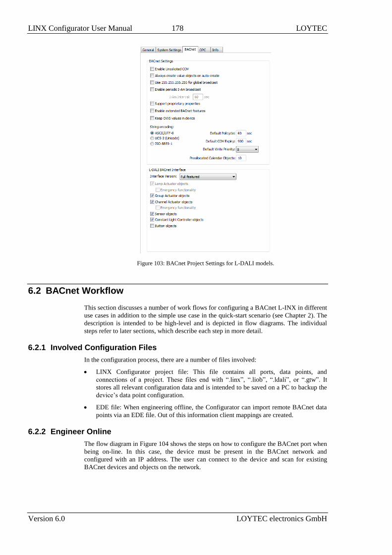
LINX Configurator User Manual 178 LOYTEC
Version 6.0 LOYTEC electronics GmbH
Figure 103: BACnet Project Settings for L-DALI models.
6.2 BACnet Workflow
This section discusses a number of work flows for configuring a BACnet L-INX in different
use cases in addition to the simple use case in the quick-start scenario (see Chapter 2). The
description is intended to be high-level and is depicted in flow diagrams. The individual
steps refer to later sections, which describe each step in more detail.
6.2.1 Involved Configuration Files
In the configuration process, there are a number of files involved:
LINX Configurator project file: This file contains all ports, data points, and
connections of a project. These files end with “.linx”, “.liob”, “.ldali”, or “.gtw”. It
stores all relevant configuration data and is intended to be saved on a PC to backup the
device’s data point configuration.
EDE file: When engineering offline, the Configurator can import remote BACnet data
points via an EDE file. Out of this information client mappings are created.
6.2.2 Engineer Online
The flow diagram in Figure 104 shows the steps on how to configure the BACnet port when
being on-line. In this case, the device must be present in the BACnet network and
configured with an IP address. The user can connect to the device and scan for existing
BACnet devices and objects on the network.

LINX Configurator User Manual 179 LOYTEC
Version 6.0 LOYTEC electronics GmbH
Start the Configurator stand-alone
Section 4.4.1
Scan BACnet network
Section 6.3.1
START
DONE
Create other BACnet server objects manually
Section 6.3.5
Select BACnet objects and use on device
Section 6.3.3
Upload configuration
Section 4.4.2
Create client mappings manually
Section 6.3.4
Download configuration to device
Section 4.4.4
Figure 104: Basic work flow to engineer on-line.
Start the Configurator in stand-alone mode and connect to the device via the FTP method
(see Section 4.4.1). If changing an existing configuration, upload the current configuration
from the device (see Section 4.4.2). In the Configurator, start an on-line network scan to
discover devices and BACnet objects (see Section 6.3.1). Select the data points that the
device shall expose (see Section 6.3.3). Alternatively, you can create client mappings (see
Section 6.3.4) and local BACnet server objects (see Section 6.3.5) manually. Finally, the
configuration needs to be downloaded to the device (see Section 4.4.4). It is recommended
to backup the device configuration to a file for being able to replace the device in the
network (see Section 4.4.6).
6.2.3 Engineer Offline
The flow diagram in Figure 105 shows the steps on how to configure the BACnet port when
being off-line. In this case, the device doesn’t need to be present in the BACnet network.
The systems integrator can engineer the BACnet port and download the configuration at a
later point in time.

LINX Configurator User Manual 180 LOYTEC
Version 6.0 LOYTEC electronics GmbH
Import BACnet data points from EDE
Section 6.3.2
START
DONE
Create other BACnet server objects manually
Section 6.3.5
Select BACnet objects and use on device
Section 6.3.3
Start the Configurator and
select the device model
Secton 4.4.1
Create client mappings manually
Section 6.3.4
Store configuration on hard drive
Figure 105: Basic work flow to engineer off-line.
Start the Configurator in stand-alone mode and select the appropriate device model in the
menu Model (see Section 4.4.1). In the Configurator, import external BACnet data points
from an EDE file (see Section 6.3.2). Select the data points that the device shall expose (see
Section 6.3.3). Alternatively, you can create client mappings (see Section 6.3.4) and local
BACnet server objects (see Section 6.3.5) manually. When finished store the configuration
on the hard drive and download later to the device (see Section 4.4.4).
6.3 BACnet Configuration
6.3.1 Scan for BACnet Objects
LOYTEC devices also support an online network scan on the BACnet network. In this scan
the device searches for other devices on the BACnet network and pulls in the BACnet
object information of these devices. These BACnet objects can then be used on the device
as the basis for client mapping.
To Scan for BACnet Objects
1. Go to the Datapoints tab.
2. Select the folder BACnet Network Scan
3. Right-click on that folder and select Scan BACnet Network…. This opens the
BACnet Network Scan dialog as shown in Figure 106.

LINX Configurator User Manual 181 LOYTEC
Version 6.0 LOYTEC electronics GmbH
Figure 106: BACnet network scan dialog.
4. Click on the button Discover Devices. This starts a network scan. To narrow down the
scan range and reduce scanning time, enter a device ID range into the Scan from and
to fields. The results are put in the device list box. A progress bar below indicates how
many devices are being scanned.
5. Select a device in the device list and click the button Scan Objects. This scans the
BACnet objects on the selected device and adds them to the BACnet Network Scan
folder as a separate sub-folder for the device.
6. If the scan does not give the expected results, change the Device Scan Mode to normal
or slow and try again. With this setting the scanner uses simpler but slower protocol
features.
7. Click Close when all devices needed have been scanned.
Note: If proprietary properties access on a remote device is required, support for proprietary
properties must be enabled in the BACnet tab of the Project Settings dialog (see Section
6.1).
6.3.2 Import from EDE File
If the device is engineered offline or some of the required BACnet devices are not yet
online in the network, the engineering process can be done by importing a device and object
list from a set of EDE files. These objects also appear in the import folder and can be later
used on the device as client mappings.
There are a set of EDE files. Select the main EDE file, e.g. device.csv. The EDE import will
also search for the other components, which must be named device-states.csv. Which
components are expected, please refer to the Chapter “Operating Interfaces” of the
LOYTEC Device User Manual [1]. Example EDE files can be found in the ‘examples’
directory of the LOYTEC Configurator software installation directory.
To Import BACnet Objects from an EDE File
1. Go to the Datapoints tab.
2. Select the folder BACnet EDE File

LINX Configurator User Manual 182 LOYTEC
Version 6.0 LOYTEC electronics GmbH
3. Right-click and select Import File. In the following file selector dialog, choose the
EDE import file and click OK.
4. Now the BACnet EDE File folder is populated with the imported BACnet objects.
6.3.3 Use Imported BACnet Objects
After BACnet objects have been imported (with a network scan or by importing from an
EDE file) the user can select the BACnet objects that the device shall access. When
executing the Use on device the configuration software allocates client mappings on the
device. These client mappings will read or write values from the BACnet objects in the
network.
In an additional step, there can be also server objects allocated on the device. These server
objects can be created automatically from converting a client mapping to a server object.
This is usually done, if the imported BACnet objects shall also be directly modified over the
BACnet network on the device itself.
To Use Imported BACnet Objects on the Device
1. Open the data point manager dialog and select the desired BACnet objects in one of the
import folders.
2. Use the multi-select feature by holding the Shift or Ctrl keys pressed.
3. Click on the button Use on Device in the tool bar.
4. This creates data points in a remote device sub-folder of the BACnet Port/Datapoints
folder. All data points in that folder will be created as client mappings. No server object
is created automatically in this case.
5. To also create server objects select the data points in question using the multi-select
feature. Then activate the property Allocate Server Object in the section Advanced.
6. For editing the client mapping, you may multi-select client map data points and edit the
corresponding data point properties Client Confirmed COV, Client COV Expiry,
Client Map Type, Client Write Priority, Remote Instance Number.
6.3.4 Create a Client Mapping
The client mapping information can also be created manually. Usually, this is done to create
client data points without importing information from EDE or scanning online.
To Create a Client Mapping
1. Select the Datapoints folder under the BACnet Port folder.
2. Right-click in the data point list and select New Datapoint… in the context menu. This
opens the Create New BACnet Point dialog as shown in Figure 107.

LINX Configurator User Manual 183 LOYTEC
Version 6.0 LOYTEC electronics GmbH
Figure 107: Create Client Mapping Dialog.
3. Select the tab Client Mapping.
4. Choose a target device in the list of known devices. Enter a Data Point Name, choose
an Object Type, and edit the target object instance number. Then select the Mapping
Type. For read client mappings edit the COV expiry or Pollcycle setting. For write
client maps edit the Write Priority. For value client maps edit both. When finished
click Create Client Mapping.
5. For an analog client mapping define a Network Unit. This is the engineering unit of
the remote object. Optionally, define a unit representation of the remote scalar value for
the metric (SI) and U.S. unit system on the device.
6.3.5 Create Server Object
On the BACnet port server objects can also be created manually. These BACnet objects are
visible on the BACnet network and can be modified by other devices. They appear as data
points in the BACnet/Datapoints folder.
To Create Server Objects Manually
1. Select the Datapoints folder under the BACnet Port folder.
2. Right-click in the data point list and select New Datapoint… in the context menu. This
opens the Create New BACnet Point dialog as shown in Figure 108.

LINX Configurator User Manual 184 LOYTEC
Version 6.0 LOYTEC electronics GmbH
Figure 108: Create a Server Object manually.
3. In the Mandatory Properties enter a Datapoint Name and an Object Type.
Optionally, update the Instance No and select the Commandable check box for value
objects, if the value object shall be commandable from the network.
4. In the Optional Properties you may select Unit SI and Unit U.S. for analog objects.
BACnet objects have no fixed network unit. Depending on the chosen unit system, the
analog BACnet object will be created with the specified metric (SI) or U.S. unit in the
engineering unit property.
5. For all object types you can enter the Description. The Device Type can be left empty.
For multi-state objects you have to select a multi-state map.
6. Click Create Server Object. The BACnet data point is created and appears in the data
point list.
6.3.6 Export Server Objects to an EDE File
When engineering offline it can be beneficial to hand out the server object configuration of
the device to other parties electronically. For doing so you may export the server object
configuration to a set of EDE files. The set of EDE files consist of the main EDE file, e.g.
myDevice.csv. This file contains the list of all objects and refers to state texts that are
exported to a second file named myDevice-states.csv. For which components are exported
in an EDE file, please refer to the Chapter “Operating Interfaces” for BACnet in the
LOYTEC Device User Manual [1].
To Export an EDE File
1. Select the BACnet Port folder.
2. Right-click and select Export EDE … in the context menu. This opens the EDE export
dialog to enter the EDE header information as shown in Figure 109.

LINX Configurator User Manual 185 LOYTEC
Version 6.0 LOYTEC electronics GmbH
Figure 109: EDE Export Dialog.
3. Click the button to select the EDE file export location.
4. Specify the Device Name and Device Instance. The device instance will be used by
other tools to configure their BACnet clients for accessing the exported device.
5. Optionally fill in project name, author to document that information in the EDE file.
6. Click Export.
6.3.7 Import Server Objects from an EDE File
It is also possible to import a BACnet server object interface from EDE files. In this use
case, the device is configured to resemble a the device of the EDE file. If conflicts in
instance numbers or object names arise with already existing server objects, the imported
objects are re-assigned.
There are a set of EDE files. Select the main EDE file, e.g. device.csv. The EDE import will
also search for the other components, which must be named device-states.csv. Which
components are expected, please refer to the Chapter “Operating Interfaces” for BACnet in
the LOYTEC Device User Manual [1].. Example EDE files can be found in the ‘examples’
directory of the LOYTEC Configurator software installation directory.
To Import BACnet Server Objects from an EDE File
1. Select the folder BACnet Port
2. Right-click and select Import Server Objects from EDE…. In the following file
selector dialog, choose the EDE import file and click OK.
3. Now a folder for the device in the EDE file is generated and a report is displayed,
informing about the imported objects and possible reassignments.
6.3.8 Map other Properties than Present_Value
When creating a BACnet server object, the Present_Value property is mapped by the
created data point. That means writing and reading on the data point reads or writes the
Present_Value. If other properties shall be accessed, they must be added to the BACnet
server object’s data point.
To Add other BACnet Properties
1. Select the BACnet server object for adding properties.

LINX Configurator User Manual 186 LOYTEC
Version 6.0 LOYTEC electronics GmbH
2. Right-click on the data point and select Add/Remove BACnet properties … from the
context menu. The dialog appears as shown in Figure 110.
Figure 110: Dialog for adding/removing BACnet properties.
3. Check the additional properties. Checking the Read box will add an input data point,
checking the R/W box will add a value data point.
4. Click Close. The selected data point can now be expanded with the plus icon and show
its additional properties as sub-data points.
5. To remove properties perform the same steps and uncheck the corresponding check-
boxes. Alternatively, select the property (or more) and press the Delete key.
6.3.9 Enable International Character Support
By default BACnet objects on the device contain ASCII strings in properties such as object
name, description, active/inactive text, state texts. This is the setting most third-party tools
are interoperable with. To support international character sets, the device can be configured
to expose strings as ISO-8895-1 (for most Western European languages) or UCS-2 (for
Unicode character sets such as Japanese).
To Enable International Character Support
1. In the Configurator software menu go to Settings Project settings …. This opens
the Project Settings dialog (see also Section 6.1).
2. Click on the tab BACnet.
3. Put a check mark either on ASCII/UTF-8 (default), UCS-2 (Unicode, e.g., for
Japanese), or ISO-8859-1 (for Western European languages).
4. Click OK.
5. Download the configuration to activate the change.

LINX Configurator User Manual 187 LOYTEC
Version 6.0 LOYTEC electronics GmbH
6.3.10 Read the Active Priority
In BACnet objects that possess a priority array the effective value depends on the used write
priority slots. A special data point on the device can be added that allows reading out the
active priority of such an object, giving a value between 1 and 16.
To Read the Active Priority of a Local Object
1. Select the BACnet server object for adding properties.
2. Right-click on the data point and select Add/Remove BACnet properties … from the
context menu. The dialog for mapping BACnet properties to data points appears.
3. For the Present_Value select the additional box Active Priority.
To Read the Active Priority of a Feedback Value
1. Select a write client mapping.
2. Right-click on the data point and select Create Priority Feedback Point from the
context menu.
3. A new data point is created, which is a feedback client mapping that reads the active
priority out of the remote object.
6.3.11 Write and Read with Priority
In BACnet objects that possess a priority array the effective value depends on the used write
priority slots. As default, data points for those objects have the direction input, which is
intended to read the resulting value. Additional priority write output data points can be
added for writing to the BACnet object. For those data points, a write priority between 1
and 16 can be defined. The default write priority is defined by the project settings.
To read back the value at a given priority slot, additional priority read input data points can
be added. They reflect the value at the configured priority slot between 1 and 16. If the
priority slot is NULL the data point stays at invalid value.
To Create a Priority Write Data Point
1. Select the commandable BACnet server object.
2. Right-click and select Create Priority Write Point… from the context menu.
3. A dialog prompts for the write priority. Note that the write priority can also be changed
later.
4. The new priority write data point appears below the original BACnet server object data
point.
To Create a Priority Read Data Point
1. Select the commandable BACnet server object.

LINX Configurator User Manual 188 LOYTEC
Version 6.0 LOYTEC electronics GmbH
2. Right-click and select Create Priority Read Point… from the context menu.
3. A dialog prompts for the read priority. Note that the read priority can also be changed
later.
4. The new priority read data point appears below the original BACnet server object data
point.
6.3.12 Duplicate BACnet Devices with Data Points
When importing BACnet devices via network scan or EDE file, the resulting client
mappings are used on the device. For each BACnet device a sub-folder is created which
organizes the client mapping data points for that device. The BACnet device itself appears
in the BACnet device manager. After editing the client mapping data points as appropriate,
entire device folders can serve as templates for duplication. The created copies of the data
points are pointing to an unassigned device, which can be commissioned later on the Web
interface.
To Duplicate BACnet Devices
1. Select a folder created for a scanned/imported BACnet device.
2. Right-click and choose Duplicate in the context menu.
3. The Duplicate data points and set naming rules dialog opens as shown in Figure
111.

LINX Configurator User Manual 189 LOYTEC
Version 6.0 LOYTEC electronics GmbH
Figure 111: Duplicate BACnet devices.
4. In the Data Point Assignment section choose to assign the duplicated data points to a
new BACnet device instance and click OK.
5. A new BACnet device folder is created with the duplicated client mapping data points.
The original BACnet device is also duplicated, leaving the actual device instance
number empty and marking the device to be commissioned later on the Web interface
as described in the LOYTEC Device User Manual [1].
6. The BACnet Device Manager shows the created devices as depicted in Figure 112.
Figure 112: Duplicated BACnet devices for later commissioning.

LINX Configurator User Manual 190 LOYTEC
Version 6.0 LOYTEC electronics GmbH
7 M-Bus
7.1 Configurator
This section describes how to use the Configurator software for the management of M-Bus
data points. For further information on the Configurator software refer to Chapter 4.
7.1.1 Activating M-Bus Configuration
Before a new M-Bus configuration can be managed, the M-Bus option must be enabled.
The project settings are described in detail in Section 4.3.
To Activate the M-Bus Configuration
1. Open the project settings dialog.
2. In the Device Configuration tab enable the M-Bus check box.
3. Press the OK button.
Important: If the M-Bus Port is deactivated via the checkbox or a firmware or model version is
chosen, which does not support M-Bus, the complete M-Bus configuration is deleted. In
this case a dialog is displayed, which has to be confirmed.
7.1.2 Data Point Manager for M-Bus
The Configurator uses a central concept to manage data points. The data point manager is
used to select, create, edit and delete data points. The dialog is divided into three sections:
The folder list (Figure 113)

LINX Configurator User Manual 191 LOYTEC
Version 6.0 LOYTEC electronics GmbH
The data point list (Figure 114),
And a property view.
Figure 113: Data Point Manager Dialog with M-Bus folder list
Figure 114: Datapoint Manager Dialog with M-Bus Data Point List.
7.1.3 Folder List
At the left is a list of folders which is used to sort the available data objects by their
category. There are a number of predefined M-Bus folders available. All other folders are
described in section 4.2.1:
Imported: This folder has a number of sub-folders for different import methods:
o M-Bus Network Scan: This folder holds data points scanned online from an
attached M-Bus network. When scanning an M-Bus device, a subfolder is
created under M-Bus Network Scan. The name of this subfolder is generated
automatically from the information of the scanned device. Additionally under
the device sub-folder a data point folder is created.
Device Templates: This folder contains created data point templates for the different
technologies.
o M-Bus Device Templates: This folder contains a sub-folder for each device,
which is imported from an M-Bus device template. This device folder also
contains a sub-folder with the data points specified in the template. Data
points can be added to the folder. Additionally suitable data objects can be
created for the use on the device by selecting the Use on Device option.
Filter templates: This folder contains filter templates for scanned M-Bus devices

LINX Configurator User Manual 192 LOYTEC
Version 6.0 LOYTEC electronics GmbH
o M-Bus: This folder contains a folder with data points for each created filter
template.
LINX-XXX: This is the device folder (see Section 4.2.1). For M-Bus an additional
port folder exists:
o M-Bus Port: This folder contains the remote M-Bus data points, which are
used on the device.
7.1.4 Network Port Folders
The M-Bus network port folder on the device has the same structure of sub-folders as the
other network port folders in Section 4.2.2. Currently only the Datapoints folder exists for
the M-Bus network port.
7.1.5 M-Bus Properties
Apart from the common data point properties discussed in Section 4.2.4 the data points of
the M-Bus technology have additional properties:
Storage Number: This property defines the M-Bus storage number of the data point.
This number can also be specified by the manufacturer using a DIF/DIFE combination.
Tariff: This property defines the tariff of the M-Bus data point. This number can also
be specified by the manufacturer using a DIF/DIFE combination.
Subunit: This property defines the subunit of the M-Bus data point. This number can
also be specified by the manufacturer using a DIF/DIFE combination.
Function Field: This property defines the function field of the M-Bus data point.
Possible values for this property are instantaneous value, maximum value, minimum
value and value during error state. This number can also be specified by the
manufacturer using a DIF/DIFE combination.
Data Coding: This property defines how the value for this data point is coded. The
information is not relevant for input data points but it is mandatory for output data
points. Possible values for this property are instantaneous value, maximum value,
minimum value and value during error state. This number can also be specified by the
manufacturer using a DIF/DIFE combination.
VIF/VIFE: The VIF and VIFE (Value Information Field and VIF Extension) specify
the counter type and its scaling. When the most significant bit of a VIF or VIFE is set,
another VIFE follows. Up to ten VIFEs can be specified. When this combination is
entered, also the M-Bus counter type and the unit are updated according to the
VIF/VIFE combination.
M-Bus Counter type: This information is derived from VIF/VIFE. It informs about
the type of the data point value (e.g. Energy counter value or operating time).
M-Bus Device Name: This property shows the name of the M-Bus device the remote
data point is connected to.
M-Bus Device Address: This property shows the address name of the M-Bus device
the remote data point is connected to.
M-Bus Pollgroup: Each M-Bus input data point is attached to a poll group. If more
than one poll group is available, the poll group can be selected. This property is not
shown for output data points.
M-Bus Poll Mode: Usually M-Bus data points are read via a default read or a selective
read (REQ_UD2 telegram specifying the appropriate data point). When this value is set
to Defined by device setting, the method which is specified in the device settings is
used. Using Default Read or Selective Read overrides the device setting for this data
point. It is advised to leave this option at the default setting and adapt it only, if a
device requires a different configuration for some specific data points.

LINX Configurator User Manual 193 LOYTEC
Version 6.0 LOYTEC electronics GmbH
7.1.6 M-Bus Device Capabilities
Communication to an M-Bus device can be configured with a number of options to match
the target device’s capabilities. Some of them are important to treat special behavior of
certain M-Bus devices on the market. In principle, the device capabilities specify, what kind
of M-Bus read requests the device is able to process and which other preconditions apply.
Default Read: If nothing else is specified, the default read method is used. Default read
usually means that the M-Bus device transfers all available data during a read
operation.
Selective Read: Selective read means that the particular data point to be read can be
selected during the read request. If the device is able to perform such a request, the
selective read method should be chosen as it saves bandwidth.
Send NKE before default read: If this option is enabled, an NKE message is sent to
the device before sending the default read request. This reinitializes the M-Bus device.
Devices which send multi-telegram messages start with their first telegram in the next
read request; it is advised to set this option for these devices. Please note that some
devices perform a complete device reset when they receive an NKE message. In this
case the read request may fail. Please refer to the manufacturer’s manual of the M-Bus
device for more information.
Send application reset before default read: If this option is enabled, an application
reset is sent to the device before sending the default read. Please refer to the
manufacturer’s manual of the M-Bus device for detailed information.
Ignore multi-telegram message: This flag only has an impact on reading M-Bus
devices, which send multi-telegram messages. In this case, the transfer is aborted after
the reception of the first telegram. It is advised to also set the Send NKE before
default read when setting this flag.
Max. per Request: This setting specifies the maximum number of data points to be
specified within one selective read request (REQ_UD2 telegram).
7.2 M-Bus Workflow
This section discusses the workflows for setting up an M-Bus environment. The network
can either be set up online using the network scan function or also offline by either setting
up the devices and data points manually or by using M-Bus device templates. The change of
primary addresses and Baud rates can only be done online.
7.2.1 Offline Engineering
This section describes how an M-Bus network can be set up without using the M-Bus
network. Figure 115 shows the workflow. First, the M-Bus devices, address and Baud rates
of the M-Bus devices must be configured for example by following the device manu-
facturer’s guidelines (see Section 7.3.3). Afterwards the devices and data points are
configured in the Configurator either configured manually (see Section 7.3.4) or by using
M-Bus device templates (see Section 7.3.5). Also mixing the two methods is possible.
When using the device templates also data points can be added manually. The configuration
is then downloaded to the device and the device is rebooted (see Section 4.4.4).

LINX Configurator User Manual 194 LOYTEC
Version 6.0 LOYTEC electronics GmbH
START
Configure addresses and Baud rates of the M-Bus devices
Section 7.3.3
M-Bus Data Points
Section 7.3.4
Download Configuration to device
Section 4.4.4
DONE
Import M-Bus Device Templates
Section 7.3.5
Figure 115: Workflow for offline engineering.
7.2.2 Online Engineering
This section describes how the M-Bus network is set up when the network can be accessed.
Figure 116 shows the workflow. If necessary the addresses and Baud rates the M-Bus
devices are using can be configured using the Configurator (see Section 7.3.3). The devices
and data points can then be configured by scanning the connected devices (see Section
7.3.2), manual configuration (see Section 7.3.4) or also by using the M-Bus device
templates (see Section 7.3.5). The configuration is then downloaded to the device and the
device is rebooted (see Section 4.4.4).
START
Download Configuration to device
Section 4.4.4
DONE
M-Bus devices already configured
in the network?
yes
Configure M-Bus devices (change
baudrate, change address)
Section 7.3.3
no
Manually Configure M-Bus devices and
data points
Section 7.3.4
Scan M-Bus devices and data points
Section 7.3.2
Import M-Bus device templates
Section 7.3.5
Figure 116: Workflow for online engineering.

LINX Configurator User Manual 195 LOYTEC
Version 6.0 LOYTEC electronics GmbH
7.3 Using the Configurator for M-Bus
7.3.1 Automatic Naming
Operations which automatically generate M-Bus data points or allocate M-Bus devices use
auto naming. Automatic naming is also used, when a device is applied and no device name
is specified.
The automatic device name is concatenated from the device medium (e.g. Electricity), the 3
character M-Bus manufacturer code and the address. For example the device could be
automatically named “Electricity_LOY_7”. If a name is specified, the device name of the
applied device is concatenated the address, e.g., “Device_7”.
The automatic data point name is concatenated from the device name the data point is
related with and the type of the data point. For example if a data point is an energy counter
value in the device “Electricity_LOY_7”, the name “Electricity_LOY_7_Energy” is
created.
7.3.2 Scanning the M-Bus Network
The Configurator software can connect to the device and perform an M-Bus network scan.
The network scan searches for connected M-Bus devices and data points on those devices.
The device scan goes through each address on the M-Bus network using the specified Baud
rates. When scanning for a device the M-Bus scanner starts with the highest specified Baud
rate. If the device is found, it is added to the device list, if not, the scan tries to find the
device address with the next lower Baud rate and so on.
The M-Bus scan can only scan for input data points. Output data points can be created
manually or imported via a device template.
To Scan for Devices
1. Connect to the device via FTP as described in section 4.4.1.
2. Right click on the Folder M-Bus Network Scan and select Scan M-Bus Network.
This opens the M-Bus Network Scan Dialog shown in Figure 117.
Figure 117: M-Bus Network Scan dialog.
3. In M-Bus Transmission Settings choose the address scanning mode. The default is
secondary address scanning. This prevents problems with duplicate primary addresses
of previously uninstalled M-Bus devices.

LINX Configurator User Manual 196 LOYTEC
Version 6.0 LOYTEC electronics GmbH
4. Select all applicable Baud rates for the device scan.
Important: Selecting 300 Baud results in a very slow scan. Aborting the scan is possible using the
Abort Device Scan button
5. Start the scan by pressing the Start Device Scan button. The progress bar shows the
progress of the scan. Under the progress bar, a text displays, which device is currently
scanned. When a device is found, it is displayed in the device list. The name of the
device is automatically created as described in section 7.3.1.
6. The scan can be aborted by selecting the Abort Device Scan button.
7. When the device scan is finished (either aborted or ended), the devices can be selected
for a data scan. Also multi-select is possible.
8. Select the devices which have to be scanned for data points and press the Scan Device
Data button. This scans all data points of the selected devices. For every device a
folder with the name of the device is created under the M-Bus Network Scan folder.
The data points found are placed in the Datapoints folder of the appropriate devices.
To Use Datapoints from a Scan
1. Go to the Datapoints folder of the device of the M-Bus scan.
2. Select the desired data points, also multi-select is possible.
3. Either press on the Use on Device button or right-click and select Use on Device.
The selected data points are now available in the Datapoints subfolder of the M-Bus
Port folder.
To Create Filter Templates from a Network Scan
1. Go to the Datapoints folder of the device of the M-Bus scan.
2. Select the desired data points, you wish to create a template from, also multi-select is
possible.
3. Right click on one of the selected data points and select Use as Template. This creates
a folder, containing the selected data points.
To Use data points from a Scan using Filter Templates
1. Right click on the folder M-Bus Network Scan and select either Use on device and
apply single M-Bus filter templates or select Use on device an apply all M-Bus
filter templates. When all filter templates are applied, all matching data points from
the scan are used on the M-Bus port of the device.
2. When Use on device and apply single M-Bus filter templates is selected, the
following dialog is opened:

LINX Configurator User Manual 197 LOYTEC
Version 6.0 LOYTEC electronics GmbH
3. The drop down box shows all available M-Bus filter templates. As additional
information, when a filter template is chosen, the number of data points is displayed,
which match the template.
4. Select OK to use the data points on the device.
7.3.3 Network Management Functions
This section describes how the M-Bus network management functions can be used. It
describes adding and removing M-Bus devices as well as changing the Baud rate or the
primary address. The tasks can be performed offline as well as online.
The Network Management dialog shown in Figure 118 shows a list of devices. Devices
which have been scanned using a network scan have the status online, devices which have
been created manually or using device templates have the status offline. If a device which is
online also has been scanned for device data, a green checkmark is displayed in the Data
column.
To Start the M-Bus Network Management Dialog
1. Connect to the device via FTP as described in section 4.4.1.
2. Select the M-Bus dialog by clicking on the M-Bus button
in the tool bar of the Datapoints tab. The M-Bus Management dialog opens, showing
the Network Management tab displayed in Figure 118.

LINX Configurator User Manual 198 LOYTEC
Version 6.0 LOYTEC electronics GmbH
Figure 118: M-Bus network management dialog.
To Add an M-Bus Device Manually Without Scanning
1. Fill in the Device Address and select a Device Baudrate from the drop down box.
2. A Device Name can be specified. If more devices with the same properties have to be
created using subsequent addresses, the end address can be specified in the input field
on the right hand side of the Device Address field.
3. If the device shall be created without knowing the address of any physical device, leave
the above address fields empty and select Commission later. This device can then be
commissioned on the Web UI as described in the LOYTEC Device User Manual [1].
4. The device capabilities specify, what kind of M-Bus read requests the device is able to
process. If nothing is specified here, Default Read is used. For other options please
refer to Section 7.1.6.
5. The optional device information just represents manufacturer details and model details.
This information is used in two cases:
a. The device name is not specified – in this case a device name is automatically
created from the optional device information. The name is concatenated to
MAN_Medium_address, where MAN is the 3 character manufacturer code,
Medium is the M-Bus medium (e.g. “Heat”) and address is the specified
address.
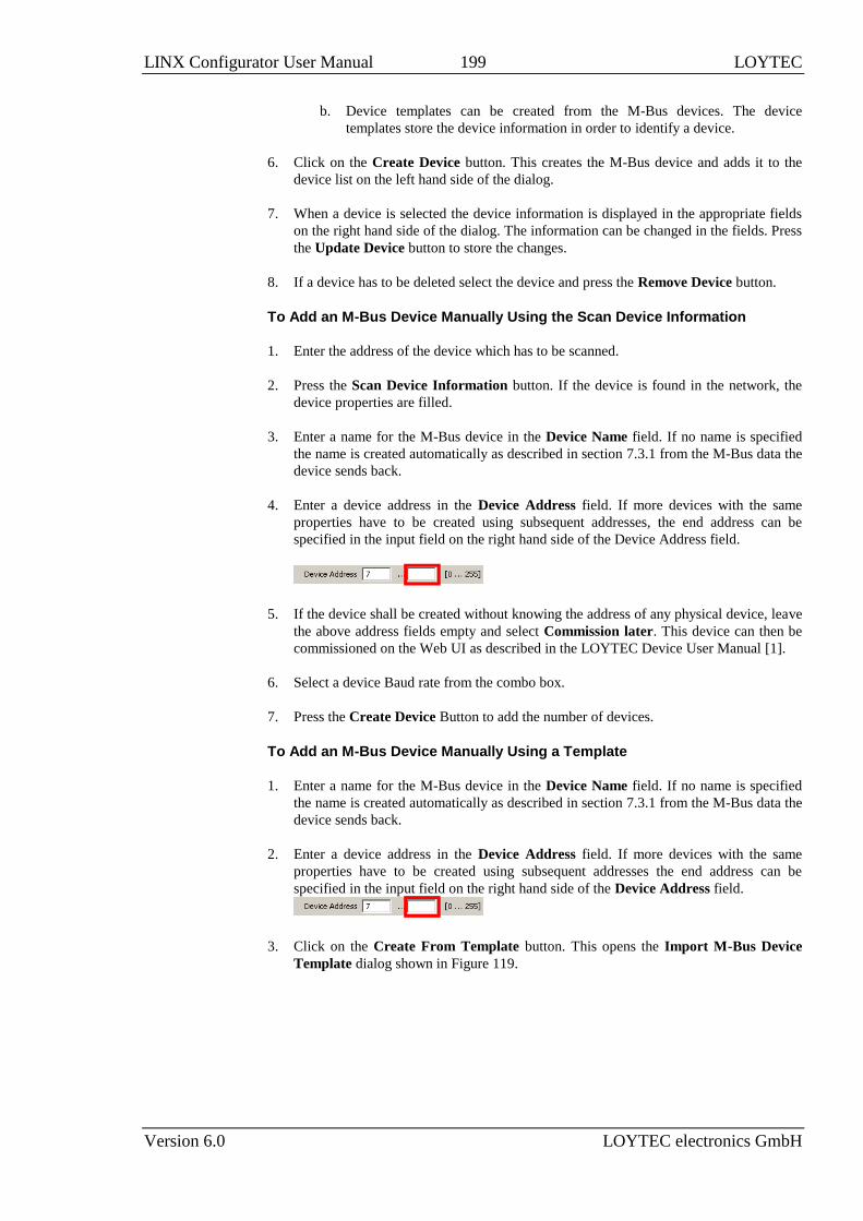
LINX Configurator User Manual 199 LOYTEC
Version 6.0 LOYTEC electronics GmbH
b. Device templates can be created from the M-Bus devices. The device
templates store the device information in order to identify a device.
6. Click on the Create Device button. This creates the M-Bus device and adds it to the
device list on the left hand side of the dialog.
7. When a device is selected the device information is displayed in the appropriate fields
on the right hand side of the dialog. The information can be changed in the fields. Press
the Update Device button to store the changes.
8. If a device has to be deleted select the device and press the Remove Device button.
To Add an M-Bus Device Manually Using the Scan Device Information
1. Enter the address of the device which has to be scanned.
2. Press the Scan Device Information button. If the device is found in the network, the
device properties are filled.
3. Enter a name for the M-Bus device in the Device Name field. If no name is specified
the name is created automatically as described in section 7.3.1 from the M-Bus data the
device sends back.
4. Enter a device address in the Device Address field. If more devices with the same
properties have to be created using subsequent addresses, the end address can be
specified in the input field on the right hand side of the Device Address field.
5. If the device shall be created without knowing the address of any physical device, leave
the above address fields empty and select Commission later. This device can then be
commissioned on the Web UI as described in the LOYTEC Device User Manual [1].
6. Select a device Baud rate from the combo box.
7. Press the Create Device Button to add the number of devices.
To Add an M-Bus Device Manually Using a Template
1. Enter a name for the M-Bus device in the Device Name field. If no name is specified
the name is created automatically as described in section 7.3.1 from the M-Bus data the
device sends back.
2. Enter a device address in the Device Address field. If more devices with the same
properties have to be created using subsequent addresses the end address can be
specified in the input field on the right hand side of the Device Address field.
3. Click on the Create From Template button. This opens the Import M-Bus Device
Template dialog shown in Figure 119.

LINX Configurator User Manual 200 LOYTEC
Version 6.0 LOYTEC electronics GmbH
Figure 119: Import M-Bus Device dialog.
4. Press the button and select a template file from the Open dialog.
5. After selecting the file, the device information is displayed.
6. Press Import for importing the template or Cancel for closing the dialog without any
changes.
7. When a template is imported, a folder with the name of the device is created. Under
this folder a Datapoints folder containing the data points from the template file is
created.
Tip: Data points can be added to the data points of the template by right-clicking in the data
point list and selecting New Datapoint.
When you want to create one or more device instance together with its data points, use
the button Create with DP instead of the button Create From Template. This creates the
device instance, all the data points from the template can be found in the M-Bus Port’s
data points folder.
To Remove an M-Bus Device
1. Select the device which has to be removed, also multi-select is possible.
2. Press the Remove Device button. If the device already has data points, these data
points have to be deleted before the remove can be performed.
To Change the Properties of an M-Bus Device
1. Select the device. This shows the device properties.
2. Update the field Device Address or select another Baud rate in the combo box.
3. Press the button Update Device.
4. If a device address is specified, which already exists, a failure message is displayed.

LINX Configurator User Manual 201 LOYTEC
Version 6.0 LOYTEC electronics GmbH
To Scan Devices Using the M-Bus Network Management Dialog
1. Select the Baud rate for the device scan. For more information on scanning the M-Bus
network refer to Section 7.3.2.
2. Start the scan by pressing the Scan for Devices button.
3. When the device scan is finished, the devices can be selected for a data scan. Also
multi-select is possible.
4. Select the devices which have to be scanned for data points and press the Scan Device
Data button. This scans all data points of the selected devices. For every device a
folder with the name of the device is created under the M-Bus Network Scan folder.
The data points found are placed in the Datapoints folder of the appropriate devices.
Important: If a device, which is scanned, is already in the device list, the existing device can either be
overwritten; deleting all previously scanned data points of the existing device or the
scanned device can be discarded. A dialog is displayed for this decision.
7.3.4 Manual Configuration of Data Points
It is possible to manually configure M-Bus data points. Manual configuration is done by
specifying all information, the M-Bus device manufacturer provides.
To Manually Create an M-Bus Data Point
1. Click on the M-Bus port Datapoints folder.
2. Right click in the data point list view and select New Datapoint in the context menu.
3. This opens the Create New M-Bus Datapoint dialog shown in Figure 120.
Figure 120: Create M-Bus Object dialog.

LINX Configurator User Manual 202 LOYTEC
Version 6.0 LOYTEC electronics GmbH
4. If the M-Bus device which provides the data point is not in the list, it has to be created.
In this case open the Network Management dialog by clicking the Edit M-Bus Devices
button.
5. Create the device in the Network Management dialog and close the dialog.
6. Select the device which provides the M-Bus data point.
7. The data point properties are entered in the group Datapoint Properties as shown in
Figure 120.
8. Enter a data point name. If no name is entered, the data point is named as described in
section 7.3.1.
9. At the moment only analog M-Bus data points are supported. Select if the data point is
an analog input or output. For analog inputs no M-Bus data coding can be specified.
10. Select if the data point shall be specified by providing the numbers for Storage number,
tariff, subunit, function field and data coding or if the information configured using the
DIF/DIFE list.
For reference, if one piece of information is entered, the other one is derived from the
specified data. Enter the data point information.
If the DIF list is entered, the dialog expects hexadecimal numbers. As soon as the
information is entered the other fields are updated.
11. Enter the VIF/VIFE list. This list specifies the M-Bus counter type, and unit of the data
point. Also this field has to be specified using hexadecimal numbers.
12. Usually data points are added to a default poll group. If the data point has to be
member of another poll group than default, the poll group can be selected using the
drop down box.
In the drop down box the previously specified poll groups are shown. If no poll group
is configured only the default poll group is displayed. Refer to section 7.3.7 for more
information on poll groups.
13. The FIV list defines the network unit of the M-Bus data point. In addition you may
choose its representation in the selected unit system.

LINX Configurator User Manual 203 LOYTEC
Version 6.0 LOYTEC electronics GmbH
14. Press the Create button to create the M-Bus data point
Tip: After creating a data point, the poll group can be changed in the data points property
view. Also multi-select can be used.
7.3.5 Importing via Device Templates
For some M-Bus devices special templates are available which specify all available data
points of an M-Bus device as well as the device properties. Such templates can be imported
into the configuration.
To import an M-Bus Device Template
1. Right click on the Folder M-Bus Device Templates and select Import device
template from the context menu.
2. This opens the Import M-Bus Device Template dialog shown in Figure 121.
Figure 121: Import M-Bus Device Template dialog.
3. Press the button and select a template file from the Open dialog.
4. After selecting the file, the device information is displayed.
5. Press Import for importing the template or Cancel for closing the dialog without any
changes.
6. When a template is imported, a folder with the name of the device is created. Under
this folder a Datapoints folder containing the data points from the template file is
created.
Tip: Data points can be added to the data points of the template by right clicking in the data
point list and selecting New Datapoint.
Importing a device template from the folder list does not create a device instance. Device
instances can only be created using the import in the Network Management Dialog.

LINX Configurator User Manual 204 LOYTEC
Version 6.0 LOYTEC electronics GmbH
To Use Imported Data Points
Using imported data points is a little different to the use of scanned data points. For a
scanned device a device instance already exists – the important information address and
Baud rate – devices imported from templates do not have an address or Baud rate.
1. Go to the Datapoints folder of the device of the M-Bus Templates.
2. Select the desired data points, also multi-select is possible.
3. Either press on the Use on Device button or right-click and select Use on Device.
This opens the M-Bus Configure Device For Use dialog shown in Figure 122.
Figure 122: Use on Device dialog.
4. The device list displays all devices which have the same Manufacturer ID, version
number and Medium. If no device instance matches the device template, create one by
entering the network management dialog. The dialog can be entered by pressing the
Edit M-Bus Devices button. In the management dialog, the device instance can be
either created manually (take care of entering the correct Manufacturer ID, Version and
Medium) or by simply importing the template again.
5. Select one or more device instances from the list and press the Use On Device button.
This creates for each selected data point and each selected device one data point in the
M-Bus Port’s data point list.
7.3.6 Creating Device Templates
M-Bus device templates can be created from a data point configuration. In fact, it is only
possible to create a device template using an existing device or an existing device template
with data points. This device and its data points can either be configured manually, by a
scan or also imported from a device template itself.
An M-Bus device template contains the following configuration items describing an M-Bus
device:
M-Bus device settings,
M-Bus data points,
Folders used to organize M-Bus data points on a device,

LINX Configurator User Manual 205 LOYTEC
Version 6.0 LOYTEC electronics GmbH
Structure types, multi-state maps, historic filters used by M-Bus data points,
Pollgroup definitions used by M-Bus data points.
To Create an M-Bus Device Template Using Devices
1. Select the M-Bus dialog by clicking on the M-Bus button
in the tool bar of the Datapoints tab. This opens the Network Management dialog as
displayed in Figure 123.
Figure 123: M-Bus Network Management dialog.
2. The device list shows all devices of the current configuration. Select a device.
3. Press the Export Device Template button. This opens the M-Bus Export Template
dialog.

LINX Configurator User Manual 206 LOYTEC
Version 6.0 LOYTEC electronics GmbH
4. Press the button and select a template file from the Save dialog.
5. Enter the Creator, Company Name and Version for the template. This information is
stored in the template file, when importing the template file the information is displayed
after selecting the file.
6. Press the Export button.
To Create an M-Bus Device Template File Using a Device Template
1. Right-click on the folder of the device template that has to be exported or its data point
folder and select Export Device Template… from the context menu.
2. Proceed as described above to export the template in the Export M-Bus Device
Template dialog.
7.3.7 Poll Groups
In an M-Bus network, the master has to poll the slave devices. Input data points are
therefore attached to a poll group. If nothing else is specified, the default poll group is used
for input data points. The default poll group has a poll cycle of 60 seconds.
Three different types of poll groups can be specified:
Time-based: The poll group is triggered on a time base. This means that after a
specific time – the poll cycle – the poll group is processed.
Trigger-based: The poll group is triggered on a special trigger data point. As soon
as the trigger condition is met, the poll group is processed.
Trigger-based with synchronization: This type is similar to the trigger-based. The
difference is that when the trigger condition is met, a broadcast synchronization
message is sent over the M-Bus. This causes the devices which are able to perform
a sync operation to store special data points for later reading. After the broadcast is
sent, the poll group is processed.
Tip: If an M-Bus device is only able to process default read requests, it is advisable to attach all
data points of this device to the same poll group (this increases the performance).
The poll group a data point is attached to can be changed in the properties view of the data
points. The poll group can also be changed for multiple data points using multi-select.
To Create a Time-Based M-Bus Poll Group
1. Select the M-Bus dialog by clicking on the M-Bus button
in the tool bar of the Datapoints tab. The M-Bus Management dialog opens.
2. Open the Pollgroups tab. This shows the dialog displayed in Figure 124.

LINX Configurator User Manual 207 LOYTEC
Version 6.0 LOYTEC electronics GmbH
Figure 124: Pollgroup Management dialog.
3. The default poll group is selected and its properties are displayed. Enter the name of
the new poll group and enter the poll cycle in seconds. Make sure that under Pollgroup
Mode Time-based is selected.
4. Press the Save button to store the poll group and continue editing.
5. If a poll group needs to be updated or deleted, select the poll group edit the data and
press the Update Selected or Delete Selected button.
6. Press the Close button to finish editing. When the poll groups have not been saved, a
dialog asks whether the changes have to be saved or not.
To Create a Trigger-Based M-Bus Poll Group
1. Select the M-Bus dialog by clicking on the M-Bus button
in the tool bar of the Datapoints tab.
2. In the M-Bus Management dialog, open the Pollgroups tab. This displays the poll
groups management tab displayed in Figure 124.
3. Enter a new poll group name and select Trigger-based or Trigger-based with
synchronization.
4. Create the poll group by pressing the Create New button.
5. Select the new poll group. This enables the Add… and Remove buttons from the
triggers.

LINX Configurator User Manual 208 LOYTEC
Version 6.0 LOYTEC electronics GmbH
6. Press the Add… button and select a trigger data point. This can for example be a
binary user register.
7. The selected trigger data point appears in the trigger list as shown:
8. Select the trigger from the list and check the desired trigger conditions.
9. The trigger conditions are then displayed in the trigger list.
10. Press the Close button to leave the dialog.
7.3.8 Trending Synchronized Meter Data
The use of trigger-based poll groups with synchronization allows trending synchronized
meter data. A trigger data point triggers a synchronization message over the M-Bus
network. The M-Bus meters which are able to perform the synchronization action store the
meter values. These values are read out afterwards.
To Trend Synchronized Meter Data
1. Create a binary trigger data point.
2. Create a trigger-based poll group with synchronization.
3. Create a trend log as described in Section 4.9. Set the Trend Mode to Change of
Value (COV) and add all required data points.
7.3.9 M-Bus Protocol Analyzer
When connected to a device a protocol analyzer is available for the M-Bus port. The
protocol analyzer can be found in the M-Bus Management dialog. Figure 125 shows the
dialog for the M-bus protocol analyzer.
The status on the right hand side of the dialog shows, if the device is connected or if the
protocol analyzer is stopped or started. When connected to a device, the protocol analyzer
can be started by pressing the Start Protocol button. This starts the protocol analyzer in the
device. Every time a transmission is made on the M-Bus port, the transmission is displayed
in the list. Additionally the protocol data is stored in the device in a rotating log file. The
protocol log can hold up to 40 kB of protocol data. So also when the Configurator was not
running for an interesting time, the protocol data can be loaded from the device using the
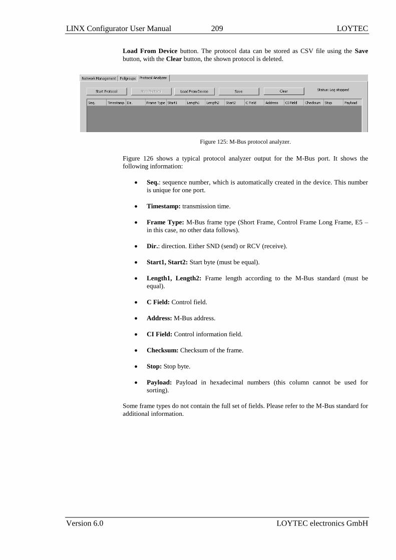
LINX Configurator User Manual 209 LOYTEC
Version 6.0 LOYTEC electronics GmbH
Load From Device button. The protocol data can be stored as CSV file using the Save
button, with the Clear button, the shown protocol is deleted.
Figure 125: M-Bus protocol analyzer.
Figure 126 shows a typical protocol analyzer output for the M-Bus port. It shows the
following information:
Seq.: sequence number, which is automatically created in the device. This number
is unique for one port.
Timestamp: transmission time.
Frame Type: M-Bus frame type (Short Frame, Control Frame Long Frame, E5 –
in this case, no other data follows).
Dir.: direction. Either SND (send) or RCV (receive).
Start1, Start2: Start byte (must be equal).
Length1, Length2: Frame length according to the M-Bus standard (must be
equal).
C Field: Control field.
Address: M-Bus address.
CI Field: Control information field.
Checksum: Checksum of the frame.
Stop: Stop byte.
Payload: Payload in hexadecimal numbers (this column cannot be used for
sorting).
Some frame types do not contain the full set of fields. Please refer to the M-Bus standard for
additional information.

LINX Configurator User Manual 210 LOYTEC
Version 6.0 LOYTEC electronics GmbH
Figure 126: Typical protocol analyzer output for M-Bus port.
7.3.10 Device Replacement
This section describes how an M-Bus device can be replaced using the M-Bus network
management functions.
To Replace an M-Bus Device on the Network
1. Connect to the device via FTP as described in Section 4.4.1.
2. Disconnect the device which has to be replaced from the M-Bus and connect the new
device to the network.
3. Start the M-Bus device scan (see Section 7.3.2). The new device may produce a
primary address conflict. This conflict may either be resolved automatically after the
scan or manually during device replacement.
4. Select the M-Bus dialog by clicking on the M-Bus button
in the tool bar of the Datapoints tab. The M-Bus Management dialog opens, showing
the Network Management tab displayed in Figure 118.
5. Select the device which has to be replaced and press the Replace Device button. This
opens the dialog displayed in Figure 127.
Figure 127: M-Bus Device Replacement Dialog.
6. In the replacement dialog all compatible devices for replacement are shown. If the
required device is not shown in the list, remove the check Only show exact match.

LINX Configurator User Manual 211 LOYTEC
Version 6.0 LOYTEC electronics GmbH
This will show all possible devices. Note, that only M-Bus devices can be selected as a
replacement device, which do are not yet using data points on the device.
7. Select the replacement device and press OK.
8. If the selected replacement device is still in conflict, the Configurator will suggest to
automatically update the primary address to that of the replaced device.

LINX Configurator User Manual 212 LOYTEC
Version 6.0 LOYTEC electronics GmbH
8 Modbus
8.1 Configurator
This section describes how to use the Configurator software for the management of Modbus
data points. For further information on the Configurator software refer to Chapter 4.
8.1.1 Activating Modbus Configuration
Before a new Modbus configuration can be managed, the Modbus option must be enabled
for the appropriate port. The project settings are described in detail in Section 4.3.
To Activate the Modbus Configuration
1. Open the project settings dialog.
2. In the Device Config tab enable the Modbus check boxes on the desired ports as shown
in Figure 128. Setting the check box enables Modbus on that port. Edit the Modbus
communication settings.
3. If slave mode is enabled, you may change the default Modbus register layout in the
Modbus Slave Register Configuration box.
4. Click the Download button to activate the changes in the configuration.

LINX Configurator User Manual 213 LOYTEC
Version 6.0 LOYTEC electronics GmbH
Figure 128: Project settings for Modbus.
Important: If the Modbus port is deactivated via the checkbox or a firmware or model version is
chosen, which does not support Modbus, the entire Modbus configuration is deleted. In
this case a dialog is displayed, which has to be confirmed.
8.1.2 Data Point Manager for Modbus
The Configurator uses a central concept to manage data points. The data point manager is
used to select, create, edit and delete data points. The dialog is divided into three sections:
The folder list (Figure 129),
The data point list (Figure 130),
And a property view.

LINX Configurator User Manual 214 LOYTEC
Version 6.0 LOYTEC electronics GmbH
Figure 129: Data Point Manager Dialog with Modbus folder list.
Figure 130: Datapoint Manager Dialog with Modbus Data Point List.
8.1.3 Folder List
At the left is a list of folders which is used to sort the available data objects by their
category. There are a number of predefined Modbus folders available. All other folders are
described in section 4.2.1:
Device Templates: This folder contains created data point templates for the different
technologies.
o Modbus Device Templates: This folder contains a sub-folder for each device,
which is imported from an Modbus device template. This device folder also
contains a sub-folder with the data points specified in the template. Data
points can be added to the folder. Additionally suitable data objects can be
created for the use on the device by selecting the Use on Device option.
LINX-XXX: This is the device folder (see Section 4.2.1). For Modbus additional port
sub-folders exist:
o Modbus Port RS-485: This folder contains the remote Modbus data points of
the Modbus RS-485 port, which are used on the device.
o Modbus Port TCP: This folder contains the remote Modbus data points of
the Modbus TCP port, which are used on the device.
8.1.4 Network Port Folders
The Modbus network port folder on the device has the same structure of sub-folders as the
other network port folders in Section 4.2.2. Currently only the Datapoints folder exists for
the Modbus network ports.

LINX Configurator User Manual 215 LOYTEC
Version 6.0 LOYTEC electronics GmbH
8.1.5 Modbus Properties
Apart from the common data point properties discussed in Section 4.2.4 the data points of
the Modbus technology have additional properties:
Modbus Device Name: This property defines the name of the Modbus slave device
which contains the data point.
Modbus Device Address: This property defines the address of the Modbus slave
device which contains the Modbus data point.
Modbus IP Address: This property is available for Modbus/TCP master only. It
specifies the IP address of the Modbus slave device, which contains the Modus data
point.
Modbus Register Start Address: This property defines the address of the Modbus
register.
Modbus Register Type: This property defines the register type of the data point. Also
the function code, which specifies the register, is displayed. When the Modbus register
type is changed from a read to a write register, also the direction of the data point is
changed.
Modbus Data Type: This property defines the representation of data in the slave. This
is the data type the Modbus slave uses for the data point internally. This can for
example be float, double, int16 or uint32.
Modbus Scaling (multiplier, exponent and offset): These properties define the
scaling parameters for the data point. The value of the data point in the device is
calculated as follows:
Value = (ModbusValue + Offset) ∙ Multiplier ∙ 10Exponent.
Modbus Swap 16 bit, Swap 32 bit and Swap 64 bit: This information specifies, if the
order of received Modbus data has to be changed. When Swap 16 bit is set, the two
bytes of a 16 bit word are swapped, if Swap 32 is set, the two words of 32 bit are
swapped, and if Swap 64 bit is set, the two 32 bit words of 64 bit long data are
swapped. Also combinations are possible. This configuration is necessary because the
Modbus slaves can store information in any byte order (the Modbus protocol only
specifies, how 16 bit data is transferred).
Pollgroup: This property is only available for input data points. It shows the poll
group, the data point is connected to.
8.1.6 Modbus Workflow
This section discusses the workflows for setting up a Modbus environment. Modbus does
not provide a scan function and therefore the network has to be setup mostly offline. This
can be eased by the use of templates. If no templates are available, the data points have to
be set up manually. If devices are online, an online test feature can help in identifying
Modbus registers and their settings.
Figure 131 describes the workflow for setting up a Modbus network. For using Modbus the
Modbus ports of the LOYTEC device and the Modbus devices have to be configured. The
RS-485 Modbus port must get a Baud rate, the parity is fixed at none and the stop bits are
configured to 2. The Modbus TCP port must get the TCP port number of the slave devices
The Modbus devices have to be configured according to the LOYTEC device’s port
configuration (see Section 8.2.1). When no device template is available for a Modbus
device, this template can be created by manually configuring Modbus data points for the
device (see Section 8.2.2). If the Modbus device is already online, data points can be
created using the online test feature by scanning register values out of the device (see
Section 8.2.3). In both cases the created data points can be exported as a device template.
The exported device template can then be used to easily add additional Modbus devices
with the same data point configuration (see Section 8.2.4). Also mixing the two methods is

LINX Configurator User Manual 216 LOYTEC
Version 6.0 LOYTEC electronics GmbH
possible. When using the device templates also data points can be added manually. The
configuration is then downloaded to the device and the device is rebooted (see Section
4.4.4).
START
Configure Modbus Port
Section 8.1.1
Configure Modbus Data Points manually
Section 8.2.2
Download Configuration to LINX
Section 4.4.4
DONE
Import Modbus Device Templates
Section 8.2.4
Configure Modbus devices/addresses
Section 8.2.1
Modbus Data Points with Online Test
Section 8.2.3
Figure 131: Workflow for offline engineering.
8.2 Using the Configurator for Modbus
8.2.1 Modbus Management Functions
This section describes how the Modbus network management functions can be used. It
describes adding and removing Modbus.
The Modbus Management dialog shown in Figure 132 shows the list of devices. Devices
which have been imported from a template show the template name in the last column. For
each device the address, the IP address (if available), the port and the number of data points
available on that device is shown.
The Modbus Management dialog can also be used for the configuration of poll groups and
for accessing the LOYTEC devices protocol analyzer.
To Start the Modbus Network Management Dialog
1. Connect to the device via FTP as described in section 4.4.1.
2. Select the Modbus dialog by clicking on the Modbus button
in the tool bar of the Datapoints tab. The Modbus Management dialog opens, showing
the Modbus Device Management tab displayed in Figure 132.

LINX Configurator User Manual 217 LOYTEC
Version 6.0 LOYTEC electronics GmbH
Figure 132: Modbus management dialog.
To Add a Modbus Device Manually
1. Fill in the Device Address and select the Type (either RS-485 or TCP) from the drop
down box.
2. A Device Name can be specified. If no device name is specified, the device name is
created automatically. If more devices with the same properties have to be created
using subsequent addresses, the number of devices can be specified in the input field
under the Device IP Address field. If a number of TCP devices has to be created,
subsequent IP addresses are configured. If the checkbox Increase Device Address is
checked, also the Device Addresses (unit IDs) of the TCP devices are increased.
3. The Device Address specifies the address of the Modbus device ranging from 1 to 255.
In case of a TCP device the device address specifies the unit ID. For a RS-485 device
the device address has to be unique, TCP devices can have equal device addresses.
4. For TCP devices the Device IP Address has to be specified.
5. If the device shall be created without knowing the address of any physical device, leave
the above address fields empty and select Commission later. This device can then be
commissioned on the Web UI as described in the LOYTEC Device User Manual [1].
6. If the device is not able to read adjacent registers with one read command, activate the
checkbox Single Read. If the device is not able to process writes of multiple registers
in one command, activate the checkbox Single Write.
7. The setting Multiple read limit allows limiting the number of registers in a multi-read
request. The default is disabled. Set this value, if a Modbus device has problems with
the default multi-read.

LINX Configurator User Manual 218 LOYTEC
Version 6.0 LOYTEC electronics GmbH
8. The optional manufacturer details just represent Manufacturer name and Model
name. This information is used to identify device templates.
9. Click on the Create Device button. This creates the Modbus device and adds it to the
device list on the left hand side of the dialog.
10. When a device is selected the device information is displayed in the appropriate fields
on the right hand side of the dialog. The information can be changed in the fields. Press
the Update Device button to store the changes.
11. If a device has to be deleted select the device and press the Remove Device button.
To Add a Modbus Device Manually Using a Template without Creating Data
Points
1. Enter a name for the Modbus device in the Device Name field. If no name is specified
the name is created automatically from the name in the template file.
2. Fill in the Device Address and select the Type (either RS485 or TCP) from the drop
down box. If TCP is selected also enter the Device IP Address. If more devices with
the same properties have to be created using subsequent addresses, the number of
devices can be specified in the input field under the Device IP Address field.
3. Click on the Create From Template button. This opens the Import Modbus Device
Template dialog shown in Figure 133.
Figure 133 Import Modbus Device Template dialog.
4. Press the button and select a template file from the Open dialog.
5. After selecting the file, the device information is displayed.
6. Press Import for importing the template or Cancel for closing the dialog without any
changes.
7. When a template is imported, a folder with the name of the device is created. Under
this folder a Datapoints folder containing the data points from the template file is
created.
Tip: Data points can be added to the data points of the template by right-clicking in the data
point list and selecting New Datapoint.

LINX Configurator User Manual 219 LOYTEC
Version 6.0 LOYTEC electronics GmbH
To Add a Modbus Device Manually Using a Template Creating Data Points
1. Enter a name for the Modbus device in the Device Name field. If no name is specified
the name is created automatically from the name in the template file.
2. Fill in the Device Address and select the Type (either RS-485 or TCP) from the drop
down box. If TCP is selected also enter the Device IP Address. If more devices with
the same properties have to be created using subsequent addresses, the number of
devices can be specified in the input field under the Device IP Address field.
3. Click on the Create with DP button. This opens the Import Modbus Device
Template dialog shown in Figure 133.
4. Press the button and select a template file from the Open dialog.
5. After selecting the file, the device information is displayed.
6. Press Import for importing the template or Cancel for closing the dialog without any
changes.
7. When a template is imported, a folder with the name of the device is created. Under
this folder a Datapoints folder containing the data points from the template file is
created.
8. The created device is shown in the list together with the number of data points.
To Remove a Modbus Device
1. Select the device which has to be removed, also multi-select is possible.
2. Press the Remove Device button. If the device already has data points, these data
points have to be deleted before the remove can be performed.
To Change the Properties of a Modbus Device
1. Select the device. This shows the device properties.
2. Update the properties which have to be changed.
3. Press the button Update Device.

LINX Configurator User Manual 220 LOYTEC
Version 6.0 LOYTEC electronics GmbH
4. When the device type is changed, it is verified that no device with the address exists on
the appropriate port – on RS485 the device address has to be unique, on TCP the
device IP address has to be unique.
8.2.2 Manual Configuration of Data Points
It is possible to manually configure Modbus data points. Manual configuration is done by
specifying all information, the Modbus device manufacturer provides.
To Manually Create an Modbus Data Point
1. Click on the Modbus port Datapoints folder.
2. Right-click in the data point list view and select New Datapoint… in the context menu.
3. This opens the Create New Modbus Datapoint dialog showing only the devices
which are available on the appropriate port. This dialog is shown in Figure 134.
Figure 134: Create Modbus Datapoint dialog.
4. If the Modbus device which provides the data point is not in the list, it has to be
created. In this case open the Modbus management dialog by clicking the Edit
Modbus Devices button.
5. Create the device in the Modbus Management dialog and close the dialog.
6. Select the device which provides the Modbus data point.

LINX Configurator User Manual 221 LOYTEC
Version 6.0 LOYTEC electronics GmbH
7. Enter the General Data Point Properties. These are the data point name, which is
automatically created when not specified, and the Register Type. The register type of
the data point is provided in the Modbus device documentation. The drop down menu
shows the Modbus register type, the direction (read and write) and the function code.
The data point properties are entered in the presented section of the dialog.
8. Enter the properties of the data point. The register address is specified by the
manufacturer. Select the Modbus Data Type. This type specifies how the
manufacturer stores data in the Modbus device. The Modbus Data Length is
automatically updated according to the data type. Offset, Multiplier and Exponent can
be used for mapping purposes. The Value of the data point is calculated as follows:
Value = (ModbusValue + Offset) ∙ Multiplier ∙ 10Exponent.
Modbus does not specify any byte orders of the data stored in devices. For some
devices it may be necessary to change the byte order. This is done by the check boxes
Swap 16 bit, Swap 32 bit and Swap 64 bit. When Swap 16 bit is activated, the 2 byte
of a word are swapped, when Swap 32 bit is activated, the 2 words of a 32 bit value are
swapped and if Swap 64 bit is activated, the two 32 bit words of a 64 bit value are
swapped. A preview of the byte order is shown under the check boxes.
Select the Data Point Type of the data point (analog value, multi-state or binary) –
only the types which are available for the register type-data type combination are
shown.
9. For an analog Modbus Master data point define a Network Unit. This is the unit of the
register on the Modbus device. Optionally, define a unit representation of that remote
register value for the metric (SI) and U.S. unit system.
10. Select a poll group for read data points from the Pollgroup drop down box. The drop
down box is grayed out for write registers. Additional poll groups can be configured in
the Modbus Management dialog.

LINX Configurator User Manual 222 LOYTEC
Version 6.0 LOYTEC electronics GmbH
11. In order to create a series of data points in one swoop, enter the Number of data
points to be created.
12. Press the Create button to create the Modbus data points. The register indices will be
adapted in ascending order. If data points should already exist at any of those indices,
they are skipped.
13. After the point is created the dialog is not closed, so additional data points can be
created.
Tip: After creating a data point, the poll group can be changed in the data points property
view. Also multi-select can be used in the data point property view.
8.2.3 Data Point Creation with Online Test
The Modbus technology does not provide for an online scan for devices and data points like
others do. Sometimes the data sheets from the vendors are inaccurate regarding register
indices and swap information. If the Modbus device is already online, the online test
function can be used to scan value information out of the device and create data points with
that information. The online test function can also be used to test existing data points.
To Create Data Points from Online Test
1. Connect to the device.
2. Open the Create Modbus Datapoint dialog as described in Section 8.2.2.
3. In the Modbus Device List select the Modbus device, which is online and shall be
read.
4. Enter a data point name and select the Modbus Register Type in the General
Datapoint Properties group box.
5. In the Register Properties group box select the Modbus Data Type, scaling and swap
setting as assumed.
6. In the Online Register Test area enter the Read Start Address and Number of
Modbus Registers to read. Note, that a Modbus register is always 2 Bytes long.
7. Click the Read register(s) button.
8. The data read from the Modbus device is displayed in the Read raw data box as hex
bytes and in the Value list box as interpreted data.

LINX Configurator User Manual 223 LOYTEC
Version 6.0 LOYTEC electronics GmbH
9. Adapt the value interpretation in the Register Properties area until the expected result
appears. The results are immediately visible.
10. You may enable the Read continuously option, which periodically reads the registers
and displays them in the value list. You may use this option to monitor register values
and particular registers of interest.
11. Select the register values in the Value list. You may also use multi-select.
12. Click Create Data Point. This creates data points that will provide the selected register
values.
To Check Data Points Using Online Test
1. Select one ore more existing Modbus Master data points.
2. Right-click and choose Test Selected Data Points from the context menu.
3. The Data Point Values window opens and shows the read progress for the selected
data points. For each completed read a status result and a value is shown.
8.2.4 Importing via Device Templates
For some Modbus devices special templates are available which specify all available data
points of a Modbus device as well as the device properties. Such templates can be imported
into the configuration.
To import a Modbus Device Template
1. Right click on the Folder Modbus Device Templates and select Import device
template from the context menu.
2. This opens the Import Modbus Device Template dialog shown in Figure 135.

LINX Configurator User Manual 224 LOYTEC
Version 6.0 LOYTEC electronics GmbH
Figure 135 Import Device Template dialog.
3. Press the button and select a template file from the Open dialog.
4. After selecting the file, the device information is displayed.
5. Press Import for importing the template or Cancel for closing the dialog without any
changes.
6. When a template is imported, a folder with the name of the device is created. Under
this folder a Datapoints folder containing the data points from the template file is
created.
Tip: Data points can be added to the data points of the template by right clicking in the data
point list and selecting New Datapoint.
Importing a device template from the folder list does not create a device instance. Device
instances can only be created using the import in the Network Management Dialog. In this
dialog also the device instances can also be created with their data points.
To Use Imported Data Points On the Device
1. Go to the Datapoints folder of the device of the Modbus Templates.
2. Select the desired data points, also multi-select is possible.
3. Either press on the Use on Device button or right-click and select Use on Device.
This opens the Choose Modbus Device Instance dialog.

LINX Configurator User Manual 225 LOYTEC
Version 6.0 LOYTEC electronics GmbH
Figure 136: Choose Modbus Device Instance dialog.
4. The device list displays all devices which have the same Manufacturer, and the same
Model Name as the template. If no device instance matches the device template, create
one by entering the Modbus management dialog. The dialog can be entered by pressing
the Edit Modbus Devices button. In the management dialog, the device instance can be
either created manually (take care of entering the correct manufacturer and model) or
by simply importing the template again.
5. Select one or more device instances from the list and press the Use On Device button.
This creates for each selected data point and each selected device one data point in the
Modbus Port’s data point list.
8.2.5 Creating Device Templates
Modbus device templates can be created from a data point configuration. In fact, it is only
possible to create a device template using an existing device or an existing device template
with data points. This device and its data points can either be configured manually or also
imported from a device template itself.
A Modbus device template contains the following configuration items describing a Modbus
device:
Modbus device settings,
Modbus data points,
Folders used to organize Modbus data points on a device,
Structure types, multi-state maps, historic filters used by Modbus data points,
Pollgroup definitions used by Modbus data points.
To Create a Modbus Device Template Using Devices
1. Select the Modbus dialog by clicking on the Modbus button
in the tool bar of the Datapoints tab. This opens the Network Management dialog
opens as described in Section 8.2.1.

LINX Configurator User Manual 226 LOYTEC
Version 6.0 LOYTEC electronics GmbH
2. The device list shows all devices of the current configuration. Select the device you
want to export.
3. Press the Export Device Templ. button. This opens the Export Modbus Device
Template dialog shown in Figure 137. The list on the left side of the dialog shows the
names of the data points which are exported to the template.
Figure 137 Export Modbus Device Template dialog.
4. Press the button and select a template file from the Save dialog.
5. Enter the Creator, Company Name and Version for the template. This information is
stored in the template file, when importing the template file the information is displayed
after selecting the file.
6. Press the Export button.
To Create a Modbus Device Template File Using a Device Template
1. Right-click on the folder of the device template that has to be exported or its data point
folder and select Export Device Template… from the context menu.
2. This opens the Export Modbus Device Template dialog as shown in Figure 137.
Proceed as described above.
8.2.6 Poll Groups
In a Modbus network, the master has to poll the slave devices. Input data points are
therefore attached to a poll group. If nothing else is specified, the default poll group is used
for input data points. The default poll group has a poll cycle of 60 seconds.
Two different types of poll groups can be specified:
Time-based: The poll group is triggered on a time base. This means that after a
specific time – the poll cycle – the poll group is processed.
Trigger-based: The poll group is triggered on a special trigger data point. As soon
as the trigger condition is met, the poll group is processed.
Tip: The poll group a data point is attached to can be changed in the properties view of the
data points. The poll group can also be changed for multiple data points using multi-
select.

LINX Configurator User Manual 227 LOYTEC
Version 6.0 LOYTEC electronics GmbH
To Create a Time-Based Poll Group
1. Select the Modbus dialog by clicking on the Modbus button
in the tool bar of the Datapoints tab. This opens the Modbus Management dialog.
2. Open the Pollgroups tab. This shows the dialog displayed in Figure 138.
Figure 138: Pollgroup Management dialog.
3. The default poll group is selected and its properties are displayed. Enter the name of
the new poll group and enter the poll cycle in seconds. Values in multiples of ‘0.1’ are
allowed for fast polling. Make sure that under Pollgroup Mode Time-based is selected.
4. Press the Save button to store the poll group and continue editing.
5. If a poll group needs to be updated or deleted, select the poll group edit the data and
press the Update Selected or Delete Selected button.
6. Press the Close button to finish editing. When the poll groups have not been saved, a
dialog asks whether the changes have to be saved or not.
To Create a Trigger-Based Modbus Poll Group
1. Select the Modbus dialog by clicking on the Modbus button
in the tool bar of the Datapoints tab. This opens the Modbus Management dialog.

LINX Configurator User Manual 228 LOYTEC
Version 6.0 LOYTEC electronics GmbH
2. In the Modbus Management dialog, open the Pollgroups tab. This displays the poll
groups management tab displayed in Figure 138.
3. Enter a new poll group name and select Trigger-based.
4. Create the poll group by pressing the Create New button.
5. Select the new poll group. This enables the Add… and Remove buttons from the
triggers.
6. Press the Add… button and select a trigger data point. This can for example be a
binary user register.
7. The selected trigger data point appears in the trigger list as shown:
8. Select the trigger from the list and check the desired trigger conditions.
9. The trigger conditions are then displayed in the trigger list.
10. Press the Save button to store the changes in the poll groups.
8.2.7 Create Modbus Slave Data Points
The Modbus interface of the device can also be configured to be in Modbus slave mode. In
this mode, Modbus slave data points can be created. These data points can represent any of
the supported Modbus register types. They are locally available as registers to other
Modbus masters for reading and writing. The Modbus slave registers appear like user
registers; they are value data points. The register types and indices are defined when
creating the data points. They must, however, lie within the register index range, which has
been set in the system settings for the Modbus port (see Section 8.1.1).
To Create Modbus Slave Registers
1. Select the Datapoints folder of the Modbus port.
2. Right-click in the data point list view and select New Datapoint… in the context menu.
3. This opens the Create New Modbus Datapoint dialog. In the Modbus device list there
is only the SlaveDevice entry. It cannot be de-selected.

LINX Configurator User Manual 229 LOYTEC
Version 6.0 LOYTEC electronics GmbH
4. Enter the data point name and select the desired Modbus Register Type.
5. In the Register Properties group box enter the register start address, the Modbus data
type and optionally scaling and swap settings.
6. Select the data point class, which shall be created and the number of data points below.
7. For analog Modbus Slave registers you may define a metric (SI) and U.S. unit.
Depending on the chosen unit system, the Modbus Slave register will change its
representation (i.e., its value) on the network.
8. Click on the button Create data point.
9. The number of Modbus slave register data points is created. The register indices are
incremented for each created register. If a register index is already in use, the data point
for this index is skipped. Created data points are reported with a green check mark.
8.2.8 Structured Modbus Data Points
Modbus registers are always multiples of two Bytes. Modbus devices may encode two Byte
fields or bit fields into the registers. For accessing byte or bit-fields, data point structures
can be used that provide single data points for the respective sub-fields (see Section 3.1.11).
The Configurator provides pre-defined types for byte and bit-fields in the Modbus scope:
modbus_state16 and modbus_byte2.
To Create a Structured Modbus Register
1. Create the register as described in Sections 8.2.2 and 8.2.7 and select the data point
type User.

LINX Configurator User Manual 230 LOYTEC
Version 6.0 LOYTEC electronics GmbH
2. Click the button and select a structure data type from the chooser dialog.
3. Continue with the data point creation as described in the previous Sections. The
Configurator will create structured Modbus data points.
8.2.9 Modbus Protocol Analyzer
When connected to a device a protocol analyzer is available for each Modbus port. The
protocol analyzer can be found in the Modbus Management dialog. On every Modbus port a
protocol analyzer tab is available. Figure 139 shows the Modbus protocol analyzer
The status on the right hand side of the dialog shows, if the device is connected or if the
protocol analyzer is stopped or started. When connected to a device, the protocol analyzer
can be started by pressing the Start Protocol button. This starts the protocol analyzer in the
device. Every time a transmission is made on the Modbus port, the transmission is displayed
in the list. Additionally the protocol data is stored in the device in a rotating log file. The
protocol log can hold up to 40 kB of protocol data. So also when the Configurator was not
running for an interesting time, the protocol data can be loaded from the device using the
Load From Device button. The protocol data can be stored as CSV file using the Save
button, with the Clear button, the shown protocol is deleted.
Figure 139: Modbus protocol analyzer.
Figure 140 shows a typical protocol analyzer output for the Modbus TCP port. It shows the
following information for TCP:
Seq.: sequence number, which is automatically created in the device. This number
is unique for one port.
Timestamp: transmission time.
Frame Type: ‘TCP’ or ‘Damaged’ when something happened with the frame.
Dir.: direction. Either SND (send) or RCV (receive)
Trans ID: Transaction ID
Prot ID: Protocol ID
Unit ID: Unit ID
Length: Payload length of the data frame

LINX Configurator User Manual 231 LOYTEC
Version 6.0 LOYTEC electronics GmbH
Payload: Payload in hexadecimal numbers (this column cannot be used for
sorting).
Figure 140: Typical protocol analyzer output for Modbus TCP port.
Figure 141 shows a typical protocol analyzer output for the Modbus RS-485 port. It shows
the following information for RS-485:
Seq.: sequence number, which is automatically created in the device. This number
is unique for one port.
Timestamp: transmission time.
Frame Type: RTU, ASCII or Damaged when something happened with the frame.
Dir.: direction. Either SND (send) or RCV (receive)
Addr.: Slave address
CRC: CRC of the transmission
Length: Payload length of the data frame
Payload: Payload in hexadecimal numbers (this column cannot be used for
sorting)
Figure 141: Typical protocol analyzer output for Modbus RS-485 port.
The frame type Damaged indicates that either a bad packet (malformed frame, CRC error)
was received or that no response packet was received where it is expected.

LINX Configurator User Manual 232 LOYTEC
Version 6.0 LOYTEC electronics GmbH
9 KNX
9.1 Configurator
This section describes how to use the Configurator software for the management of KNX
data points. For further information on the Configurator software refer to Chapter 4.
9.1.1 Activating KNX Configuration
Before a new KNX configuration can be managed, at least one KNX interface must be
enabled. The project settings are described in detail in Section 4.3.
To Activate the KNX Configuration
1. Open the project settings dialog.
2. In the System Settings tab enable the KNX for Port 4 and/or for the Ethernet port, as
shown in Figure 142.
3. Press the OK button.
Figure 142: Enabling KNX/TP1 and KNXnet/IP in the Project Settings Dialog.

LINX Configurator User Manual 233 LOYTEC
Version 6.0 LOYTEC electronics GmbH
Important: If the KNX Port is deactivated via the checkbox or a firmware or model version is
chosen, which does not support KNX, the complete KNX configuration is deleted. In this
case a dialog is displayed, which has to be confirmed.
If the configurator is connected to a device, the Download button can be used to download
the device configuration.
9.1.2 KNX Project Settings
The project settings dialog provides a KNX tab for interface specific KNX settings. The
interface dialog, as shown in Figure 143 allows selecting a KNX interface for editing in the
left-hand tree view. The right-hand pane allows modifying the following properties of the
selected KNX interface:
Group addressing mode: The group addressing mode defines how group
addresses are displayed numerically. This setting is a display property and has no
influence on the KNX communication itself.
o Free: The addresses are displayed as integers, e.g. 12345.
o Two-Level: The addresses are displayed as main groups (5 bit) and group
addresses (11 bit), e.g. 6/57.
o Three-Level: The addresses are displayed as main groups (5 bit), middle
groups (3 bit) and group addresses (8 bit), e.g. 6/0/57.
Unique project ID: This field contains the ETS project ID from the last import,
for example P-053C. This field is used to avoid importing two different projects
into one configuration.
Physical address: This field configures the physical (individual) address of the
device, e.g. 1.2.3. It needs to be unique in the KNX network and needs to match
the line to which the device is connected to.
The following settings are available for the KNXnet/IP interface only:
Multicast address: This IPv4 multicast address is used for sending and receiving
KNX. The default value is 224.0.23.12.
Multicast port: This UDP port number is used for sending and receiving KNX
frames. The default value is 3671. It is recommended to keep the default value, as
some KNXnet/IP devices cannot operate on alternate ports.
Multicast TTL: This is the Time to live value for UDP multicast packets. The
default value is 16.
The following fields are informational only and represent the state of the latest KNX
database import.
Project name: This field contains the ETS project name.
Project number: This field contains the ETS project number.
Contract number: This field contains the ETS contract number.
Last modification: This field contains the modification time of the ETS project.
Start date: This field contains the start date of the ETS project.

LINX Configurator User Manual 234 LOYTEC
Version 6.0 LOYTEC electronics GmbH
Project Id: This field contains the imported project Id.
Comment: This field contains the text comment of the ETS project.
Completion status: This field contains the completion status of the ETS project.
Figure 143: KNX Project Settings
Group import settings: This setting allows modifying the mapping of linked
groups:
o Create one communication object for each group: This setting will
create one communication object for each imported group.
o Create one communication object for each send group: This setting
will create one communication object for each send group and attach
linked group addresses to this communication object.
The data point naming rules tab (see Figure 144) allows specifying how data point names
are automatically derived from imported KNX communication objects and groups. The
preview shows how names would look like, when the check marks are modified. Note, that
changing the name components does not change already created KNX data points; this
setting affects only new data points created by an import.
Separator: This setting defines a separator character, which is inserted between the
data point name components. As a default no separator is configured.

LINX Configurator User Manual 235 LOYTEC
Version 6.0 LOYTEC electronics GmbH
Figure 144: KNX Data Point Naming Rules
9.1.3 Data Point Manager for KNX
The Configurator uses a central concept to manage data points. The data point manager is
used to select, create, edit and delete data points. The dialog is divided into three sections:
The folder list (Figure 145),
The data point list (Figure 146),
And a property view.
Figure 145: Data Point Manager Dialog with KNX import and device folders.
Figure 146: Data Point Manager Dialog with KNX Data Point List.
9.1.4 Folder List
At the left is a list of folders which is used to sort the available data objects by their
category. There are a number of predefined KNX folders available. All other folders are
described in section 4.2.1:
KNX TP1 File Import: This folder contains the data points from the ETS database
import for the KNX/TP1 interface.

LINX Configurator User Manual 236 LOYTEC
Version 6.0 LOYTEC electronics GmbH
KNXnet IP File Import: This folder contains the data points from the ETS database
import for the KNXnet/IP interface.
LINX-XXX: This is the device folder (see Section 4.2.1). For KNX, additional port
folders exist:
o KNX TP1: This folder contains the data points for the KNX TP1 interface.
o KNXnet IP: This folder contains the data points for the KNXnet/IP interface.
9.1.5 Network Port Folders
The KNX network port folder on the device has the same structure of sub-folders as the
other network port folders in Section 4.2.2. Currently only the Datapoints folder exists for
the KNX network port.
9.1.6 KNX Properties
Apart from the common data point properties discussed in Section 4.2.4 the data points of
the KNX technology have additional properties. These properties are shared among all data
points which are connected to the same KNX communication object.
Data Point Type: This property allows setting a data type for the data point. The
configurator restricts changes to data point types of the same bit length. The
configurator data point repository contains all common KNX data points types (DPTs).
For analog objects the DPT defines the fixed network unit.
Communication flag: This flag acts as a communication master switch for the
communication object. If it is cleared, the communication object does neither receive
nor transmit KNX frames. This flag should be typically kept on.
Read flag: The read flag enables communication objects to respond to network read
requests. If the flag is cleared, read requests are ignored. Only one object in a group
should have the read flag set. This flag is usually set to off.
Transmit flag: The transmit flag enables sending group writes to the KNX network
when the data point value is written by the application. This flag should be on for
communication objects which have at least one write data point. The configurator
automatically sets this flag when a write data point is created. If the transmit flag is
cleared and write data points exist for this communication object, the configurator asks
for confirmation before removing write data points.
Update flag: The update flag determines how the communication object reacts on
receiving read responses. If the flag is off, the communication object ignores read
responses initiated by other communication objects. If the flag is on, the
communication object treats all read responses as group writes and updates the data
point properly. This flag is usually set to off.
Write flag: The write flag enables receiving group writes from the KNX network. This
flag should be on for communication objects which have at least one read data point.
The configurator automatically sets this flag when a read data point is created. If the
write flag is cleared and read data points exist for this communication object, the
configurator asks for confirmation before removing read data points.
KNX transmission priority: This property allows selecting one of the KNX
transmission priorities for the data point, low, high and alert. Typically, this property
is set to low.
KNX send group address: The send group address is the group address used for
sending group writes. It is also automatically used as a receiving address. As the group
addresses are managed by the database import, they should not be modified manually.
The KNX project settings determine the format of this string (free, two-level or three-
level).

LINX Configurator User Manual 237 LOYTEC
Version 6.0 LOYTEC electronics GmbH
KNX receive group addresses: This is a semicolon separated list of additional receive
addresses. As the group addresses are managed by the database import, they should not
be modified manually. The KNX project settings determine the format of this string
(free, two-level or three-level).
KNX communication object ID: The communication object ID is used for identifying
a communication object. As this ID is managed internally, it should not be modified
manually.
9.2 KNX Workflow
This section discusses the workflows for adding the device to an existing KNX network.
Figure 147 shows the workflow from project start to a working device configuration. The
following sections will describe this process in detail.
START
Download configuration
DONE
yes
Configuration
OK?
Interface
Decision
no
Reserve
Physical address
Setup KNX interface
Export ETS project
Import/merge ETS project
Edit device configuration
ETS project
change
Export IEC61131 types
(LINX only)
Figure 147: Workflow for KNX projects.
9.2.1 Selecting a KNX Interface
This section describes how the device can be connected to a KNX network and how to
decide which media type is to be used:
1. If the KNX network consists of a single TP1 line, the device is simply connected to the
line via the LKNX-300.
2. If the KNX network consists of several TP1 lines and couplers, there are two options:
a. If the device shall use group addresses that are mainly used within a line,
add the device to this line. This will reduce the traffic over line couplers.

LINX Configurator User Manual 238 LOYTEC
Version 6.0 LOYTEC electronics GmbH
b. If the device shall communicate with group addresses spread over several
lines, add the device to the main line or to the area line.
3. If the KNX network contains a TP1/IP router and/or has a KNXnet/IP backbone, use
the KNXnet/IP interface.
9.2.2 Reserve a Physical Address
After selecting the line, a free physical address on this line must be reserved.
Note: To make sure that the address is reserved in ETS4, you can add an arbitrary device to the
line, rename it to “Reserved for LINX” and use the assigned address for the KNX interface.
Use this address in the interface configuration dialog (see Section 9.1.2).
9.2.3 Coupler Configuration
If the KNX network contains couplers, it must be made sure that the device receives all
group telegrams contained in the device configuration. If the network consists of a single
line, this section can be ignored.
To configure the couplers to forward all groups to the device, the following options are
available:
1. Enable the switch Pass through line couplers option in the ETS4 group address or
group range options, as shown in Figure 148. If this switch is set, the couplers will
forward the group addresses towards the main line.
2. Set the “group telegrams” coupler parameters to route instead of filter of the coupler.
As this will forward all group traffic, this is not the recommended method for larger
networks.
3. Drag & drop a group address or an address range on the line which contains the device.
This will add manual filter rules to the affected couplers.
Note: Only configure the group addresses or address ranges used by the device. Forwarding all
group telegrams to the main line will only work well for small installations due to the
backbone traffic. The coupler filter table can be previewed in the ETS4 with the coupler
context menu “Preview filter table …”
Figure 148: Setting the Pass through Line Coupler option.

LINX Configurator User Manual 239 LOYTEC
Version 6.0 LOYTEC electronics GmbH
9.2.4 Use KNX Data Types in IEC61131
KNX data points can be used in an IEC61131 program, just like other data points. With a
L-LOGICAD version as of 4.2.4, all necessary KNX data types are pre-installed. They can
be found under ‘Standard_Libs/KNX_Types’.
To use KNX data points in the IEC61131 program with an older L-LOGICAD installation,
the KNX data types have to be exported as structured text and have to be imported into a
logi.CAD library.
To export KNX types, select Manage Structured Types from the Configurator Tools
menu. Select the export button, as shown in Figure 149.
Figure 149: Export KNX types
In the Export Types to Disk dialog, as shown in Figure 150,
1. clear the filter and select the KNX category,
2. copy all KNX data types to the export list
3. select an export file (*.ST) and
4. click the save button.
1
21
31
41
Figure 150: Exporting KNX types as Structured Text.
5. In logi.CAD, create a new library KnxTypes with the context menu New → Library.
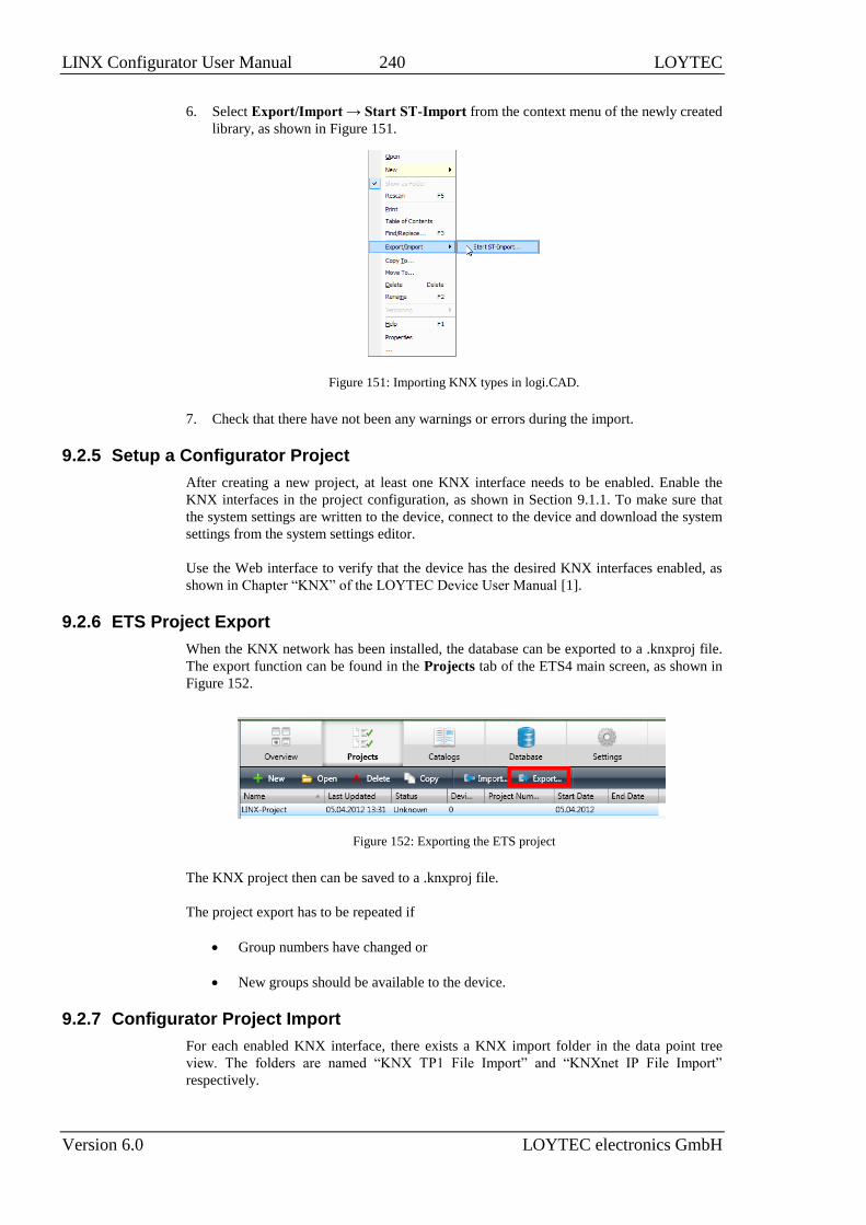
LINX Configurator User Manual 240 LOYTEC
Version 6.0 LOYTEC electronics GmbH
6. Select Export/Import → Start ST-Import from the context menu of the newly created
library, as shown in Figure 151.
Figure 151: Importing KNX types in logi.CAD.
7. Check that there have not been any warnings or errors during the import.
9.2.5 Setup a Configurator Project
After creating a new project, at least one KNX interface needs to be enabled. Enable the
KNX interfaces in the project configuration, as shown in Section 9.1.1. To make sure that
the system settings are written to the device, connect to the device and download the system
settings from the system settings editor.
Use the Web interface to verify that the device has the desired KNX interfaces enabled, as
shown in Chapter “KNX” of the LOYTEC Device User Manual [1].
9.2.6 ETS Project Export
When the KNX network has been installed, the database can be exported to a .knxproj file.
The export function can be found in the Projects tab of the ETS4 main screen, as shown in
Figure 152.
Figure 152: Exporting the ETS project
The KNX project then can be saved to a .knxproj file.
The project export has to be repeated if
Group numbers have changed or
New groups should be available to the device.
9.2.7 Configurator Project Import
For each enabled KNX interface, there exists a KNX import folder in the data point tree
view. The folders are named “KNX TP1 File Import” and “KNXnet IP File Import”
respectively.

LINX Configurator User Manual 241 LOYTEC
Version 6.0 LOYTEC electronics GmbH
To import a KNX project file, the context menu entry Import File of the import folder
needs to be selected. This opens a file requester for selecting the .knxproj-File.
After selecting the file, the configuration merge dialog is displayed, as shown in Figure 153.
This dialog allows the initial group address import and is also used to merge configuration
changes when the ETS project has evolved.
Figure 153: KNX import dialog
The top part of the dialog shows the project description. For the first import, you need to
enter the reserved physical address for this device.
The main part of the dialog is the merge editor which compares the current device
configuration with the KNX project configuration. The table displays the following
columns:
Diff: This column displays whether the group has been added (New), is unchanged
(Unchanged), has been changed (Changed), or has been removed (Removed) in
the KNX project.
Resolution: This columns allows to select different actions for each change:
o Create: This action is the default for groups that exist in the KNX project
file, but not yet in the device configuration.
o Delete: This action is the default action for groups that exist in the
configuration, but not in the KNX project file. Deleting a data point being
in use is not possible, as this would break the PLC program or the
gateway configuration.
o Update: This action changes the properties of the group, e.g. if the name
has changed.

LINX Configurator User Manual 242 LOYTEC
Version 6.0 LOYTEC electronics GmbH
o Force: This action forces the configurator to the KNX database file as the
authoritative data source, even if this will break the PLC program or
gateway configuration. It can be used to forcibly delete data points.
o Ignore: This action will ignore the change.
New name: This is the group name in the imported file.
New type: This is the data point type in the imported file.
New address: This is the group address in the imported file.
Current name: This is the group name in the current configuration.
Current type: This is the data point type in the current configuration.
Current address: This is the group address in the current configuration.
Additional controls:
The filter field above the merge editor allows a substring search to select a subset
of the imported groups. The filter can be disabled with the clear filter button.
The checkbox Show differences only allows displaying only those groups which
have changes.
The action buttons on the right top allow switching the Resolution state of the
selected data points.
If the Propagate changes to device checkbox is enabled (default), changes will
not only be updated in the import folder, but also propagated to existing data
points on the device.
The KNX project import presents all groups which are used in the KNX project by at least
one device. The default data point names are assembled by the group names, separated by
underscores.
To import or merge the KNX project configuration, press the Merge button. To leave the
device configuration unchanged, press Cancel.
9.2.8 Creating Data Points
After importing the KNX project file, the import folder contains a list of possible data
points. The data point properties can be edited in the import folder. Especially, the data type
and communication flags can be selected for each group address. Only data types matching
the configured byte length of the group address can be selected. The import folder will
typically look like Figure 154.
To use the data points on the device, multi-select the desired data points and select Use on
Device from the context menu.
When Use on Device is selected on an imported data point, the value of the communication
flags decide which data points are created:
If the Write flag is enabled, an input data point will be created.
If the Transmit flag is enabled, an output data point will be created.

LINX Configurator User Manual 243 LOYTEC
Version 6.0 LOYTEC electronics GmbH
If both, the Write flag and the Transmit flag are enabled, a value data point will
be created.
Figure 154: Imported KNX data points
9.2.9 Editing KNX Data Points
Once KNX data points have been created, they can be edited using the property editor, as
described in Section 9.1.6.
Now it is possible to use Alarming, Scheduling and Trending on the KNX data points. They
can be exposed to OPC, and can be used as parameters and IEC 61131 variables. Further
they can be used in connections, global connections and math objects.
The KNX data point properties are synchronized between the read and write properties, so
for example changing the data type of the read data point will also change the data type of
the write data point.
Note: Because the PLC program and the OPC tags are derived from the data point name, it is
advisable to keep the data point name constant. If the KNX group names are expected to be
changed, it is a good idea to create data point links in the Favorites folder and use the links
in the PLC program or for the OPC server. Then the KNX project can be merged without
having to take care of the group names.
9.2.10 Alarming, Scheduling and Trending
KNX data points can be alarmed by the generic alarm server. The configuration of alarming
is described in Section 4.8.
KNX data points can be scheduled by the generic scheduler. For devices with CEA709
interfaces, the CEA709 scheduler is used to schedule KNX networks. This works also when
the CEA709 node is no commissioned. For BACnet devices, the KNX data points can be
also scheduled by a BACnet scheduler. The configuration of scheduling is described in
Section 4.7.
KNX data points can be trended with the generic trends which are described in Section 4.9.
They can also be configured with historic filters as described in Section 4.12.

LINX Configurator User Manual 244 LOYTEC
Version 6.0 LOYTEC electronics GmbH
10 SMI
10.1 Configurator
10.1.1 Activating SMI
Before SMI devices can be added to a data point configuration, the SMI interface in the
project settings must be enabled. The project settings are described in detail in Section 4.3.
LOYTEC device models with a dedicated SMI port have this enabled as a default.
To Activate SMI in the Configuration
1. Open the project settings dialog.
2. In the System Settings tab enable the SMI protocol on the EXT port, as shown in
Figure 155.
3. Press the OK button.
Figure 155: Enabling SMI in the Project Settings Dialog.
Important: If the SMI protocol is deactivated via the checkbox or a firmware or model version is
chosen, which does not support SMI, the entire SMI configuration is deleted. In this case
a dialog is displayed, which has to be confirmed.
If the Configurator is connected to a device, the Download button can be used to download
the device configuration.

LINX Configurator User Manual 245 LOYTEC
Version 6.0 LOYTEC electronics GmbH
10.1.2 Data Point Manager for SMI
The Configurator uses a central concept to manage data points. The data point manager is
used to select, create, edit and delete data points. The dialog is divided into three sections:
The folder list (Figure 156),
The data point list (Figure 157),
And a property view.
Figure 156: Data Point Manager with SMI device folders.
Figure 157: Data Point Manager Dialog with SMI Data Point List.
10.1.3 Port Folder
The SMI port folder represents the SMI interface in the Configurator. In the SMI port
folder, one folder per SMI device is created, which contains the data points for that SMI
device. SMI device folders are identified by the SMI device icon . SMI device folders
can be deleted, renamed and organized in sub-folders.
The data points in an SMI device folder cannot be deleted or renamed. Some of their
properties such as OPC exposure, PLC in/out, parameter can be modified. The data points
per SMI device are:
Position (structure): This structured data point has the members function, setting,
rotation, which are compatible with the SNVT_setting definition. When writing
this data point the sunblind is commanded to move to the desired position/rotation.
The SMI device needs to be calibrated for this to work.

LINX Configurator User Manual 246 LOYTEC
Version 6.0 LOYTEC electronics GmbH
PositionFB (structure): This structured data point reflects the feedback of the
sunblind. Its sub-data point ‘pos’ is a SNVT_setting structure which represents the
current position of the sunblind. The sub-data point ‘error_code’ is a binary data
point that reflects an error of that device. The SMI device needs to be calibrated
for this to work.
rawPosFb (analog): This is the analog feedback value of the sunblind in raw motor
steps.
MovingDir (multistate): This feedback data point specifies the current moving
direction of the sunblind (up, down, stopped).
upHyst, downHyst, turnaround, mechSlippage, minMechAngle, maxMechAngle,
minAdjustAngle, maxAdjustAngle (analog): These are parameter data points that
contain the calibration data for the sunblind. They are filled in when calibrating the
sunblind device on the Web interface. The parameters are intended to be
distributed by the LWEB-900 parameter editor for all similar sunblinds in the
project.
Apart from the SMI device folders, a Channels folder exists. This is a fixed folder and
contains the following data points:
Power On X (X=1, 2, etc. per SMI channel): For each physical SMI channel one
power-on data point exists. This data point is set TRUE before communication on
the SMI channel commences. This can be used to attach a relay that turns on power
on the SMI channel to save energy while the motors are left idle.
Power Off Delay (analog): This data point specifies the number of seconds of idle
time until the power-on data point is deactivated again. This is a parameter by
default and thus available in LWEB-900.
10.2 SMI Workflow
10.2.1 Creating SMI Devices from Device Templates
SMI devices are created from SMI device templates. The Configurator is distributed with a
library of common device templates. Device templates can also be imported from an
external source and are stored in the data point configuration.
To Create an SMI Device
1. Click on the SMI port folder.
2. Right-click in the data point list view and select New SMI Device… in the context
menu.
3. In the Create Device dialog enter a Device Name and a Count of devices to be created
as shown in Figure 158.

LINX Configurator User Manual 247 LOYTEC
Version 6.0 LOYTEC electronics GmbH
Figure 158: SMI device creation dialog
4. Then click on and choose a template file. As a default the directory of the
distributed SMI device templates is opened. Choose the desired template file.
5. The device type, device model and device manufacturer information is displayed. Then
click Create Device.
10.2.2 Commission SMI Devices
The SMI device templates do not contain any specific addressing information. The
assignment between a device instance in the data point configuration and a physical device
has to be done later on the Commission Web interface. SMI motors also need calibration in
order to translate raw motor steps into position/rotation values.
To Commission an SMI Device
1. On the Web interface go to the menu Commission and select the SMI technology.
2. The Web UI lists all SMI devices found in the configuration. To manually assign a
device enter the serial number. If the SMI motor is online, the device is commissioned
and an address assigned.
3. Alternatively, click the Scan SMI network button below and wait for the scan to
complete.
4. From the list of scanned devices, make the SMI device assignments in the drop-down
boxes.
5. Then click the Assign button to commission the SMI devices.
For more details on the commission Web UI and motor calibration refer to the Chapter
“SMI” in the LOYTEC Device User Manual [1].
10.2.3 Organize SMI Devices
Once the SMI devices have been created, they can be modified using the context menu on
the device folder. SMI devices can be renamed, moved (but not into other devices) and
organized in sub-folders. SMI devices can also be duplicated and deleted.
To Organize SMI Devices
1. Click on the SMI port folder and create a new folder by choosing New Folder in the
context menu.
2. Select one or more SMI device folders and drag them with the mouse onto a sub-folder.

LINX Configurator User Manual 248 LOYTEC
Version 6.0 LOYTEC electronics GmbH
3. To duplicate an existing SMI device, select the SMI device folder and choose
Duplicate Device from the context menu.
4. To rename an SMI device, select the SMI device folder and choose Rename Device
from the context menu.
Note: When moving SMI device folders to other sub-folders or renaming SMI devices, their
commissioning data is maintained. When duplicating an existing SMI device, the
duplicated devices require to be commissioned.
5. To delete SMI devices, select one or more SMI device folders and choose Delete
Device from the context menu.

LINX Configurator User Manual 249 LOYTEC
Version 6.0 LOYTEC electronics GmbH
11 EnOcean
11.1 Configurator
11.1.1 Activating EnOcean
Before EnOcean devices can be added to a data point configuration, the EnOcean interface
in the project settings must be enabled. The project settings are described in detail in
Section 4.3.
To Activate EnOcean in the Configuration
1. Open the project settings dialog.
2. In the System Settings tab enable the EnOcean protocol on the USB port, as shown in
Figure 159.
3. Press the OK button.
Figure 159: Enabling EnOcean in the Project Settings Dialog.

LINX Configurator User Manual 250 LOYTEC
Version 6.0 LOYTEC electronics GmbH
Important: If the EnOcean protocol is deactivated via the checkbox or a firmware or model version
is chosen, which does not support EnOcean, the entire EnOcean configuration is deleted.
In this case a dialog is displayed, which has to be confirmed.
If the Configurator is connected to a device, the Download button can be used to download
the device configuration.
11.1.2 Data Point Manager for EnOcean
The Configurator uses a central concept to manage data points. The data point manager is
used to select, create, edit and delete data points. The dialog is divided into three sections:
The folder list (Figure 160),
The data point list (Figure 161),
And a property view.
Figure 160: Data Point Manager with EnOcean device folders.
Figure 161: Data Point Manager Dialog with EnOcean Data Point List.
11.1.3 Port Folder
The EnOcean port folder represents the EnOcean interface. In the EnOcean port folder, one
folder per EnOcean device is created, which contains the data points for that EnOcean
device. EnOcean device folders are identified by a small EnOcean logo on the folder icon
. They can be deleted, duplicated, renamed and organized in sub-folders.
The data points in an EnOcean device folder cannot be deleted or renamed. Some of their
properties such as OPC exposure, PLC in/out, parameter can be modified. The data points
named ID, Description, Location are parameters and are also available in LWEB-900.

LINX Configurator User Manual 251 LOYTEC
Version 6.0 LOYTEC electronics GmbH
11.2 EnOcean Workflow
11.2.1 Creating EnOcean Devices from Device Templates
EnOcean devices are created from EnOcean device templates. The Configurator is
distributed with a library of common device templates. Device templates can also be
imported from an external source and are stored in the data point configuration.
To Create an EnOcean Device
1. Click on the EnOcean port folder.
2. Right-click in the data point list view and select New EnOcean Device… in the
context menu.
3. In the Create Device dialog enter a Device Name and a Count of devices to be created
as shown in Figure 162.
Figure 162: EnOcean device creation dialog
4. Then click on and choose a template file. As a default the directory of the
distributed EnOcean device templates is opened. Choose the desired template file.
5. The device type, device model and device manufacturer information is displayed. Then
click Create Device.
11.2.2 Edit EnOcean Data Points
The EnOcean data points are located under their respective device folders. The data points
cannot be deleted or renamed. Some of the data point properties can be edited using the
property editor.
Now it is possible to use Alarming, Scheduling and Trending on the EnOcean data points.
They can be exposed to OPC, and can be used as parameters and IEC 61131 variables.
Further they can be used in connections, global connections and math objects.
11.2.3 Alarming, Scheduling and Trending
EnOcean data points can be alarmed by the generic alarm server. The configuration of
alarming is described in Section 4.8.
EnOcean data points can be scheduled by the generic scheduler. For devices with CEA709
interfaces, the CEA709 scheduler is used to schedule EnOcean networks. This works also
when the CEA709 node is no commissioned. For BACnet devices, the EnOcean data points
can be also scheduled by a BACnet scheduler. The configuration of scheduling is described
in Section 4.7.

LINX Configurator User Manual 252 LOYTEC
Version 6.0 LOYTEC electronics GmbH
EnOcean data points can be trended with the generic trends which are described in Section
4.9. They can also be configured with historic filters as described in Section 4.12.
11.2.4 Teach-In EnOcean Devices
The EnOcean device templates do not contain any specific addressing information. The
assignment between a device instance in the data point configuration and a physical device
has to be done later on the Commission Web interface. This is called the teach-in of
EnOcean devices.
To Teach-In EnOcean Device
1. On the Web interface go to the menu Commission and select the EnOcean technology.
2. The Web UI lists all EnOcean devices found in the configuration. To teach-in an
uncommissioned device, click the Teach-In button.
3. The device status changed to “Waiting for Device ID”. Then press the button on the
EnOcean device that shall be associated with this device in the configuration. Or click
Cancel to abort.
4. If the teach-in worked fine, the device status will change to “OK”. The RSSI value is
updated. Expand the Profile item and check the received data value.
5. Expand the Parameters item and enter a device description and location string. This
information will be available in LWEB-900 and on the Web UI.
11.2.5 Organize EnOcean Devices
Once the EnOcean devices have been created, they can be modified using the context menu
on the device folder. EnOcean devices can be renamed, moved (but not into other devices)
and organized in sub-folders. EnOcean devices can also be duplicated and deleted.
To Organize EnOcean Devices
1. Click on the EnOcean port folder and create a new folder by choosing New Folder in
the context menu.
2. Select one or more EnOcean device folders and drag them with the mouse onto a sub-
folder.
3. To duplicate an existing EnOcean device, select the EnOcean device folder and choose
Duplicate Device from the context menu.
4. To rename an EnOcean device, select the EnOcean device folder and choose Rename
Device from the context menu.
Note: When moving EnOcean device folders to other sub-folders or renaming EnOcean devices,
their teach-in data is maintained. When duplicating an existing EnOcean device the
duplicated devices require a teach-in.
5. To To delete EnOcean devices, select one or more EnOcean device folders and choose
Delete Device from the context menu.

LINX Configurator User Manual 253 LOYTEC
Version 6.0 LOYTEC electronics GmbH
12 OPC Client
12.1 Configurator
12.1.1 Port Folder
The OPC port folder represents the OPC client interface in the Configurator. In the OPC
port folder, one folder per OPC server is created, which contains the data points for that
OPC server. OPC device folders are identified by the OPC server folder icon known
from LWEB-900. OPC device folders can be deleted, renamed and organized in sub-
folders.
Data points and sub-folders in an OPC device folder can be deleted, renamed and re-
organized. Data points can also be OPC exposed, which makes them available as OPC tags
in the local OPC server. All other properties can be edited as described in Section 4.2.4.
12.1.2 Data Point Properties
Apart from the common data point properties discussed in Section 4.2.4 the data points of
the OPC client technology have additional properties.
OPC Data Type: This property shows the OPC data type of the OPC tag on the server.
OPC Tag Name: This property shows the OPC tag name on the OPC server.
OPC Tag Path: This property shows the OPC path to the tag on the OPC server.
OPC Device Commission Later: This property defines whether the OPC device in the
OPC client shall be commissioned later on the Web interface.
OPC Tag Base Path: This property shows the OPC tag base path of an imported OPC
tag list. This path can be replaced later by another path on the Web UI of the device.
OPC Device Name: This property defines the logical device name used to denote the
OPC server instance in the data point configuration. Changing it also updates the OPC
device folder name.
OPC Device Local uses HTTPS: This property specifies, whether communication to
the OPC server on the local network shall use HTTPS.
OPC Device External uses HTTPS: This property specifies, whether communication
to the OPC server from an external (public) local network shall use HTTPS.
12.1.3 OPC Device Manager
To add new OPC servers to the project or update the data points associated with an existing
OPC server, the OPC device manager window is used. It can be opened from the context
menu of the OPC client port folder. Choose Manage OPC Devices … .

LINX Configurator User Manual 254 LOYTEC
Version 6.0 LOYTEC electronics GmbH
On the top right, a tool bar is available to execute various operations.
The buttons from left to right are:
Add: Use this button to add a new OPC server from a configuration file of the
device. Supported configuration types include all L-INX, L-GATE, and L-DALI
configuration files. Once the device configuration was loaded, suitable OPC
client data points will be generated and added to the current project.
Refresh Status: This button refreshes the status of the selected OPC device. It
will check if the current data point configuration of the device is still in sync with
the data points present in the current project, or if an update is needed.
Reload: This button reloads the device configuration and updates the OPC data
points in the current project to match the current configuration of the OPC server.
Use this button to update the OPC data points whenever changes were made to
the data point configuration of the OPC server.
Select Source: This button allows you to change the device configuration file
associated with the selected OPC device. In case the name or location of the
configuration file was changed, the OPC device definition must be updated with
the new location of the file.
Open in Editor: This button will launch the configuration software suitable for
the selected OPC device and load the associated data point configuration.
Delete: This button deletes the selected OPC devices and all associated data
points. Note that once the data points have been deleted, there is no easy way to
restore them in a way that references from configuration objects to these data
points will work again. Even after adding the same device again, the new data
points will have different UIDs and all references to the old data points will be
broken.
Below the tool bar is a list of all OPC devices. Each of the device entries can be expanded
to show a number of properties. These properties can be edited and are explained below:
Name: Internal name for this OPC device. Note that changing the name will also
change the data point folder name in which the associated OPC data points are
located. In case there are templates or template instances referencing the old data
point folder name, they will need adjustment to fit the new name.
Local Address / Port: These properties specify the primary IP address and port
number which should be used to contact the OPC server.
Local use HTTPS: When this option is checked, the OPC client will use HTTPS
instead of HTTP when contacting the server.
Public Address / Port: These properties define a secondary IP address and port
number, which can be tried by the client in case the server is not reachable via the
primary address. This can be used in NATed environments, where different
addresses need to be used depending on the location of the client.
Public use HTTPS: Same as the option for the local address, but related to the
public address.
Operator Password: The operator password to use when contacting the server.

LINX Configurator User Manual 255 LOYTEC
Version 6.0 LOYTEC electronics GmbH
Write Aggregation: Time in milliseconds to wait for more values to write,
before a write request is sent to the server. This increases efficiency by reducing
the overhead involved in building and transmitting a SOAP request, compared to
the number of values written with that request.
Lower Limit to Min. Send: Minimum time in milliseconds for the Min. Send
property of the OPC data point. Any value lower than this will be replaced by the
specified minimum time.
Config Status: Shows the current status of the server configuration. The
configuration is either shown as up to date, meaning that the current project is
still in-sync with the server configuration, or the status indicates that the server
configuration was changed or removed since it was last imported.
LWEB Time: The time when the server configuration was last imported.
Source Time: The time when the server configuration was last modified.
Source Path: The location of the imported server configuration on disk.
12.2 OPC Client Workflow
12.2.1 Integrate Devices via OPC
The Configurator allows adding entire LOYTEC device configurations, which expose data
points as OPC tags. The resulting OPC device can be fully configured with its device URL
and username/password or created without addressing information to be commissioned
later. The imported OPC tags can be edited and trimmed to the required number of tags.
To Add an OPC Server
1. Select the OPC Client port folder.
2. Right-click and choose New OPC Device … from the context menu.
3. Select a LOYTEC device configuration file such as ‘.linx’ or ‘.dali’.
4. In the New OPC Device dialog select Commission later or enter an IP address or host
name and HTTP port for the Web service.
5. A new OPC device folder will be created.

LINX Configurator User Manual 256 LOYTEC
Version 6.0 LOYTEC electronics GmbH
6. Right-click on the OPC device folder and choose Rename device … from the context
menu. Enter the desired OPC device name. This name will be shown on the OPC
device commission Web page as described in the LOYTEC Device User Manual [1].
12.2.2 Integrate Sub-Trees and Relocate
Apart from integrating entire OPC servers it is also possible to import only a sub-tree. This
sub-tree has a base path that can be later replaced by another path. This makes it possible to
create tag trees on the OPC server that are identical and cover different areas, such as
‘channel1’ and ‘channel2’. When importing such a sub-tree, the assignment to channel 1 or
2 can be made later on the OPC commission Web page.
For example, the tag tree ‘User Registers.channel1’ contains the OPC tags ‘reg1’ to ‘reg3’.
The tag tree ‘User Registers.channel2’ contains exactly the same tags, that represent channel
2. The tag tree ‘User Registers.channel1’ can be exported and imported into the OPC client.
Later on the Web UI, the base path ‘User Registers.channel1’ can be replaced by ‘User
Registers.channel2’.
To Export a Tag Tree
1. Select a data point folder in a device configuration which has the desired OPC tags.
2. Right-click and choose Export OPC Tags … . Store them in a file ending ‘.opc’.
To Import a Tag Tree
1. Select the OPC Client port folder.
2. Right-click and choose New OPC Device … from the context menu.
3. Select a tag list file ending ‘.opc’.
4. In the Import OPC Device dialog, edit the device name and check Commission later.
5. Then click the Create New button. This creates a new OPC device folder for exactly
that OPC tag tree.
To Relocate a Tag Tree
1. On the Web UI go to Commission OPC XML DA Client.
2. Enter the IP address in the URL column and click the save icon.
3. The column Replacement Path shows the original OPC base path of the tag import.
4. To relocate it, enter a replacement path, e.g. ‘User Registers.channel2’. Click the save
icon.

LINX Configurator User Manual 257 LOYTEC
Version 6.0 LOYTEC electronics GmbH

LINX Configurator User Manual 258 LOYTEC
Version 6.0 LOYTEC electronics GmbH
13 ekey
13.1 Configurator
13.1.1 Activating ekey
Before ekey fingerprint reader devices can be added to a data point configuration, the ekey
interface in the project settings must be enabled. The project settings are described in detail
in Section 4.3.
To Activate ekey in the Configuration
1. Open the project settings dialog.
2. In the System Settings tab enable the ekey protocol on an RS-485 port, as shown in
Figure 163.
3. Press the OK button.
Figure 163: Enabling ekey in the Project Settings Dialog.
Important: If the ekey protocol is deactivated via the checkbox or a firmware or model version is
chosen, which does not support ekey, the entire ekey configuration is deleted. In this case
a dialog is displayed, which has to be confirmed.
If the Configurator is connected to a device, the Download button can be used to download
the device configuration.
13.1.2 Data Point Manager for ekey
The Configurator uses a central concept to manage data points. The data point manager is
used to select, create, edit and delete data points. The dialog is divided into three sections:

LINX Configurator User Manual 259 LOYTEC
Version 6.0 LOYTEC electronics GmbH
The folder list (Figure 164),
The data point list (Figure 165),
And a property view.
Figure 164: Data Point Manager with ekey device folders.
Figure 165: Data Point Manager Dialog with ekey Data Point List.
13.1.3 Port Folder
The ekey port folder represents the ekey interface. In the ekey port folder, one folder per
ekey fingerprint reader device is created, which contains the data points for that reader. The
ekey folders are identified by a small ekey logo on the folder icon . They can be deleted,
duplicated, renamed and organized in sub-folders.
The data points in an ekey device folder cannot be deleted or renamed. Some of their
properties such as OPC exposure, PLC in/out, parameter can be modified. The data points
per fingerprint reader are:
Authenticated (binary): This register becomes TRUE for a short period of time
when a finger was authenticated and then falls back to FALSE.
AuthStr (string): When a finger is authenticated, it contains the full authentication
information of user and fingerprint. After that it falls back to the empty string.
Authenticated user ID (analog): When a finger is authenticated, it contains the user
ID. After that it falls back to invalid value.
Authenticated user name (string): When a finger is authenticated, it contains the
user name. After that it falls back to the empty string.
Enable (binary): When this register is set TRUE, the finger reader is enabled and
performs authentication of fingers. When setting FALSE this particular fingerprint
reader device is disabled. This is a parameter by default and thus available in
LWEB-900.

LINX Configurator User Manual 260 LOYTEC
Version 6.0 LOYTEC electronics GmbH
EkeyAddr (string): This data point contains the ekey device address.
Users (string): This parameter data point contains the user and finger enrollment
data stored on that reader device. The parameter data point is available in
LWEB-900 and can be used to distribute user enrollment over reader devices.
Apart from the ekey fingerprint reader device folders, a Groups folder exists. This is a
fixed folder and contains 10 group enable data points:
groupEnable_X (X=0, …, 9, binary): Each of the 10 group enable registers
corresponds to a user group. Setting it FALSE temporarily denies access to all
members of the corresponding user group. Setting it TRUE allows access to all
members of the corresponding user group. This is a parameter by default and thus
available in LWEB-900.
13.2 ekey Workflow
13.2.1 Create From Device Templates
The ekey fingerprint reader devices need to be created using device templates. The
Configurator is distributed with a library of ekey fingerprint reader device templates. An
ekey device created in the data point configuration needs to be commissioned later online
on the Web UI.
To Create an ekey Reader Device
1. Click on the ekey port folder.
2. Right-click in the data point list view and select New ekey Device… in the context
menu.
3. In the Create Device dialog enter a Device Name and a Count of devices to be created
as shown in Figure 166.
Figure 166: ekey fingerprint reader device creation dialog
4. Then click on and choose an ‘.ekey’ device template file. As a default the directory
of the distributed ekey device templates is opened. Choose the desired template file.
5. The device type, device model and device manufacturer information is displayed. Then
click Create Device.

LINX Configurator User Manual 261 LOYTEC
Version 6.0 LOYTEC electronics GmbH
13.2.2 Enroll Fingerprint Readers
The fingerprint reader devices do not contain any specific addressing information. The
assignment between a reader instance in the data point configuration and a physical reader
device has to be done later on the Commission Web interface.
To Enroll a Reader Device
1. On the Web interface go to the menu Commission and select the ekey technology.
2. The Web UI lists all ekey reader devices found in the configuration. To enroll an
uncommissioned device, which is connected and online, click the Scan ekey network
button.
3. When the scan completes it lists all found ekey devices. Those which are unassigned
have a drop-down box.
4. Choose an uncommissioned reader device from the configuration and click on the
Assign button.
5. The assigned reader should now go online and show address and serial number in the
device list. Edit a description and click the save icon.
13.2.3 Enroll Users and Fingers
To enroll fingerprints for a user locate a reader device where the user has physical access.
The enrollment process is performed on that reader device. The enrollment data can then be
transferred to other reader devices that shall grant access to that user as well.
To Enroll User Fingers
1. On the commission Web UI locate the desired reader in the device list and click on the
Show users icon .
2. The user list of the selected reader device is displayed. Click on the plus icon to add
a new user.
3. To edit the user click the pencil icon which opens the User configuration page as
shown in Figure 167. Enter a user name and select a finger to enroll, e.g. left index
finger.

LINX Configurator User Manual 262 LOYTEC
Version 6.0 LOYTEC electronics GmbH
Figure 167: ekey User Configuration page.
4. Then click on the enroll button and move the correct finger as described in the
instructions.
5. Repeat this enrollment with other fingers as well. At least two fingers should be
enrolled. To finalize click on Save Settings.
To Transfer a User Configuration
1. In the ekey User Configuration page of a given user, click on the Export link to
generate a user configuration XML file.
2. Then navigate to a different reader device and pull up the User List of that device.
3. Add a new user as described above. On the user configuration page of that new user,
click on the Choose File button. Select the previously stored XML file.
4. Then click the Import button.

LINX Configurator User Manual 263 LOYTEC
Version 6.0 LOYTEC electronics GmbH
14 DALI
14.1 Configurator
To install and manage the DALI channels the tabs DALI Installation, DALI Groups,
DALI Channels, DALI Parameters and DALI Scenes are used:
The DALI Installation tab is used to assign DALI ballasts to Lamp Actuator
objects, DALI sensors to Sensor objects, and DALI buttons to Button objects.
Additionally, a name can be assigned to each ballast, sensor, and button. For
details see Section 14.1.1.
The DALI Groups tab is used to assign ballasts to DALI groups. Additionally, a
name can be assigned to each group. For details see Section 14.1.2.
The DALI Channels tab can be used to virtually connect two DALI channels
(“bridging”). Additionally, a name can be assigned to each channel. For details see
Section 14.1.3.
The DALI Parameters tab is used to configure parameters related to DALI
devices, groups and channels and to the lighting application (if available). For
details see Section 14.1.4.
The DALI Scenes tab can be used to set up DALI lighting scenes. For details see
Section 14.1.5.
14.1.1 DALI Installation Tab
The DALI Installation tab is shown in Figure 168. It is used to scan a DALI channel and
assign DALI devices to Lamp Actuator, Sensor objects, and Button objects. The dialog is
divided into three sections:
The channel selection and functions section (number 1 in Figure 168).
The DALI network database with the device assignment (number 2 in Figure 168).
The DALI network scan results (number 3 in Figure 168).

LINX Configurator User Manual 264 LOYTEC
Version 6.0 LOYTEC electronics GmbH
Figure 168: DALI Installation tab.
14.1.1.1 Channel Selection and Functions Section
The following functions are available in on-line and off-line mode:
The drop down box to the left of this section allows you to choose the DALI
channel to work with. The default selection is Channel 1. The number of channels
available depends on the device model.
In the middle of this section the drop down box Mains-Off handling and the
parameters Mains-On delay and Mains-Off delay are found. This function allows
saving the standby energy consumed by the ballasts, by switching off the ballast
mains when all ballasts on a channel are off. For further details see the LOYTEC
Device User Manual [1].
The Export and Import buttons on the right side allow exporting and importing
the DALI configuration of the selected channel to/from an XML file. This includes
DALI device assignment, device names, group assignment, group names, and the
channel configuration.
If you are online the following additional functions are available:
The Scan Channel button starts a scan of the DALI channel. When pressing the
button a window showing the scan progress will be shown (see Figure 169). After
the scan the devices found will be listed in the DALI network scan results section
(number 3 in Figure 168) of the DALI Installation tab.
Pressing the Reset button will clear the DALI configuration of the selected channel
including all DALI device assignments, device names, group assignment, group
names, and the channel configuration. If on-line it will also reset all DALI devices
on the channel to factory defaults.
Figure 169: DALI channel scan progress.
The Automatic Status check box allows enabling and disabling the periodic
update of the status of the devices in the DALI network database. Pressing Get

LINX Configurator User Manual 265 LOYTEC
Version 6.0 LOYTEC electronics GmbH
Status allows updating the device status manually if automatic status update is
disabled.
Note: If there is no IP connection available, disable automatic status update in case there is no
need to monitor the status of DALI devices as the status update uses network bandwidth.
The Protocol Analyzer button will open the DALI Protocol Analyzer window.
See Section 14.1.6 for details.
14.1.1.2 DALI Network Database Section
This section allows naming DALI devices (ballasts, sensors, and buttons) and assigning
them to the Lamp Actuator, Sensor, and Button objects. Optionally the DALI device type
can be configured for unassigned ballasts and buttons. The upper table contains 64 entries,
one for each potential DALI ballast on the channel, the middle table contains – depending
on the model – 16 or 64 entries, one for each potential DALI sensor on the channel, and the
lower table contains 64 entries, one for each potential DALI button device on the channel.
For each entry the tables contain the following columns:
Lamp/Sensor/Button name: Contains the name of the DALI device. Double click
on the name to modify it. The name should be chosen in a way which allows
identifying the lamp (e.g. room number/ballast number). This is specifically
important in off-line work flow (see Section 14.2.2) for the installer to pick the
correct lamp during the final on-line phase and to identify a lamp if it reports an
error.
Type: Show the type and optionally the make of the DALI ballast, sensor, or
button assigned. For assigned and online ballasts this information is read from the
ballast. In case of unassigned ballasts and buttons, the DALI device type can be
chosen using a drop-down box or Set device type… from the context menu (can
be used with multi-select). Selecting the device type allows to configure DALI
device type specific parameters during off-line preparation including the button
functions. Further, this information is used during device assignment when on-line
to ensure only a matching device type can be assigned. For information on the
device type reported by a ballast please refer to the documentation provided by the
vendor of the ballast or luminaire.
Status: Shows the status of the DALI device if a DALI ballast, sensor, or button is
assigned and the DALI configuration was downloaded. If the DALI device is
online the status is OK, if it is not reachable via the DALI network it is Offline.
The device is marked modified if its configuration/assignment was changed, but
not yet downloaded to the device. If Automatic Status is checked the status is
periodically updated. Press Get Status to manually trigger an update of the Status
column.
Short Addr.: Shows the DALI short address of the device. The DALI short
address can be in the range 0 to 63.
Serial Nr.: Shows the serial number of the device, if available. If the serial number
of the device is known during preparation phase of off-line work flow (see Section
14.2.2) it can be entered by double clicking on this field. In this case the
assignment is automatically performed once the DALI configuration is downloaded
to the device.
The list can be sorted by clicking on one of the column headers.

LINX Configurator User Manual 266 LOYTEC
Version 6.0 LOYTEC electronics GmbH
A device can be winked by selecting the corresponding row and clicking on the Wink
button located between the DALI network database section and the DALI scan result
section.
14.1.1.3 DALI Network Scan Result Section
If a DALI network scan has been performed by pressing the Scan Channel button, the
unassigned devices found during the scan are displayed in the table in the DALI network
scan result section.
For each entry the tables contain the following columns:
Short Addr.: Shows the DALI short address of the device. For DALI devices
which do not contain a short address it will be automatically assigned during
network scan.
Device: Can be Ballast, Sensor, Button, or Unknown. Unknown devices are
devices not supported by the LOYTEC DALI interface. See the LOYTEC Device
User Manual [1] for details on the different DALI device types.
Type: Show the type and optionally the make of the DALI device.
Serial Nr.: Shows the serial number of the device, if available.
The list can be sorted by clicking on one of the column headers.
Devices found during a DALI network scan can be assigned to Lamp Actuator, Sensor, or
Button objects either one by one or using the Auto Assign button.
To manually assign a device select one device in the scan results list on the right side and an
unassigned entry in the Lamp Actuator, Sensor, or Button objects lists on the left side and
press the Assign button. Alternatively you can drag a device from the scan results list and
drop it to an unassigned entry in the object lists. DALI ballasts must be assigned to Lamp
Actuator objects. DALI sensors must be assigned to Sensor objects. DALI buttons must be
assigned to Button objects.
To remove an assignment from an object select the corresponding entry and press the
Unassign button. The entry in the object list will become unassigned again and the DALI
device will be moved to the scan results list to the right.
To identify a device in the scan results list select the corresponding row and click on the
Wink button. The duration of the Wink action can be chosen in the drop down box besides
the button. When a device winks it dims between its minimum and maximum value for the
specified wink duration.
Tip! Use auto assign if you do not care about the assignment of a specific device. This is
typically the case if you are using the on-line work flow (do not prepare DALI installation
off-line) and you do not use the Lamp Actuator objects to control the lights (rather use
Group or Channel Actuator objects).
14.1.2 DALI Groups Tab
The DALI Groups tab is shown in Figure 170. It is used to assign DALI ballasts to groups
and setup group names.
Similar to the DALI Installation tab the drop down box in the top left corner of the tab
allows you to choose the DALI channel to work with. Below there is a table which contains
one row for each DALI ballast (64) and one column for each DALI group (16). To
add/remove a device to/from a group check/uncheck the check box where the corresponding

LINX Configurator User Manual 267 LOYTEC
Version 6.0 LOYTEC electronics GmbH
row and column are crossing. The default name of a group (e.g. “Group 00”) can be
changed by double clicking on it.
Figure 170: DALI Groups tab.
The checkbox Recover group information from devices allows keeping the group
configuration in the devices (ignoring the group configuration defined in the LINX
Configurator). It is automatically unchecked if the group configuration is changed with the
LINX Configurator.
14.1.3 DALI Channels Tab
The DALI Channels tab is shown in Figure 171. It is only available if the device is equipped
with more than one DALI channel. This tab is used to change channel names and to
configure DALI channel bridging.
Figure 171: DALI Channels tab.
The default name of a channel (e.g. “Channel 1”) can be changed by double clicking on it in
the first row of the table.
To connect two channels by channel bridging, check the check box where the corresponding
row and column are crossing. For more details on the DALI channel bridging function refer
to the LOYTEC Device User Manual [1].
14.1.4 DALI Parameter Tab
The DALI Parameters tab as shown in Figure 172. The dialog is divided into the following
sections:
The tree view (number 1),

LINX Configurator User Manual 268 LOYTEC
Version 6.0 LOYTEC electronics GmbH
the object list (number 2),
the parameter view (number 3),
the constant light controller bindings and button functions view (number 4) and
buttons for special functions (number 5).
Figure 172: Parameter Configuration Dialog
The selected node in the tree view (1) determines which objects are displayed in the list
view (2). If the root node (e.g. LDALI-3E104) is selected, all objects are displayed, if
a branch is selected, the objects in or below this branch are displayed. For example,
selecting LDALI-3E104/Lamp Actuators displays all Lamp Actuator objects on all
DALI channels, whereas selecting LDALI-3E104/Lamp Actuators/Channel 1
displays only Lamp Actuators of DALI channel 1.
In the object list (2) one or multiple objects can be selected. The properties of the selected
object(s) are displayed and can be edited in the parameter view (3). In this way it is possible
to change a parameter for multiple objects at once.
All DALI ballast, sensor, group and channel parameters can be configured. On L-DALI
models in addition the parameters of the Constant Light Controller objects and Sunblind
Controller objects (LDALI-10x only) are available. Details on the L-DALI parameters can
be found in the L-DALI User Manual [3].
In case a single Constant Light Controller is selected the constant light controller bindings
section (4) becomes active and allows determining which sensors (occupancy & lux) are
used as inputs to and which light groups are controlled by the selected constant light
controller instance.
Click on the to add an input or output. Use the drop down box to select a sensor (input)
or a light group (output). Click on to remove an input or output. When adding the first
manual CLC binding on a channel all automatic bindings of that channel will be disabled.
Automatic bindings can be re-enabled in the CEA-709 Settings tab of the Project Settings
(see Section 5.1.2).

LINX Configurator User Manual 269 LOYTEC
Version 6.0 LOYTEC electronics GmbH
For each constant light controller one lux level sensor, but up to 16 occupancy sensor inputs
can be configured. Whenever at least one occupancy sensor reports occupancy the area
controlled by the controller instance is considered occupied.
Similar for each of the two light bands up to 16 DALI groups can be selected as outputs.
The primary light band is near the inside of the building, the secondary light band is near
the window front. Depending on the outdoor light intensity the primary light band has to be
brighter than the secondary light band to illuminate the room evenly. On LDALI-10x
models NV bindings can be used in parallel to the internal CLC bindings.
In case one or more Button objects supporting button functions are selected the section for
button function configuration (4) becomes active (see Figure 173). It allows the
configuration of the function executed when a button is operated.
Note: Not all DALI button device types are configurable. Therefore, a button device type
supporting button functions must be selected or assigned on the DALI installation tab
before the corresponding button object can be configured.
Figure 173: Button function configuration.
For DALI push-button coupler devices the Mode drop down box allows to select whether a
switch or a push button is connected to the button input. The Function drop down box
allows selecting the function to be performed when the button is pressed. See Table 9 for a
list of available function. If the function is used to control light, the Destination column
allows selecting the DALI group or channel to be controlled. If the function requires
additional arguments (e.g. dim values or scene numbers) they are configured in the columns
Argument 1 and Argument 2.

LINX Configurator User Manual 270 LOYTEC
Version 6.0 LOYTEC electronics GmbH
Function Description
Disabled No action
Network data point Button input status will be reflected by a data point.
On (maximum) Switch on (recall maximum).
On (last value) Switch on to last known value.
Note: Requires storing value when switching off.
Auto (Re-)activate L-DALI constant light controller of target group.
Off Switch off.
Off (store value) Store last value and switch off.
On/Off Toggle between on and off whenever button is pressed or
switch is changed depending on current status (changeover
switch). Switch light on when it is off and switch light off
when it is on.
Auto/Off Toggle between active L-DALI constant light controller and off
whenever button is pressed or switch is changed depending on
current status (changeover switch). Switch light on when it is
off and switch light off when it is on. Note: Switching off will
deactivate the L-DALI constant light controller.
Up Dim up while button is pressed. The dim speed is determined
by the fade rate parameter of each ballast.
Down Dim up while button is pressed. The dim speed is determined
by the fade rate parameter of each ballast.
Up/Down Toggle between dimming up and down whenever button is
pressed. Dim as long as button is kept pressed. The dim speed
is determined by fade rate parameter of each ballast.
On/Up Switch on (recall maximum) if button is pressed shortly, dim
up when button kept pressed. The dim speed is determined by
the fade rate parameter of each ballast.
On (last value)/Up Switch on to last known value if button is pressed shortly, dim
up when button kept pressed. The dim speed is determined by
the fade rate parameter of each ballast.
Auto/Up (Re-)activate L-DALI constant light controller if button is
pressed shortly, dim up when button kept pressed. The dim
speed is determined by the fade rate parameter of each ballast.
Note: Diming up will deactivate the L-DALI constant light
controller.
Off/Down Switch off value if button is pressed shortly, dim down when
button kept pressed. The dim speed is determined by the fade
rate parameter of each ballast.
Off (store value)/Down Store last value and switch off if button is pressed shortly, dim
down when button kept pressed. The dim speed is determined
by the fade rate parameter of each ballast.
On/Off and Up/Down Toggle between on and off whenever button is pressed shortly
depending on current status (changeover switch). Toggle
between dimming up and down whenever button is pressed
longer. Dim as long as button is kept pressed. The dim speed is
determined by the fade rate parameter of each ballast.
Auto/Off and Up/Down Toggle between active L-DALI constant light controller and off
whenever button is pressed shortly depending on current status
(changeover switch). Toggle between dimming up and down
whenever button is pressed longer. Dim as long as button is
kept pressed. The dim speed is determined by the fade rate
parameter of each ballast. Note: Diming up/down and
switching off will deactivate the L-DALI constant light
controller.

LINX Configurator User Manual 271 LOYTEC
Version 6.0 LOYTEC electronics GmbH
Function Description
On (last value)/Off and
Up/Down
Toggle between switching on to last value and off (including
storing the last value) whenever button is pressed shortly
depending on current status (changeover switch). Toggle
between dimming up and down whenever button is pressed
longer. Dim as long as button is kept pressed. The dim speed is
determined by the fade rate parameter of each ballast.
Dim to Dim to the value entered as argument 1.
Dim to (toggle) Toggle between dim value entered as argument 1 and dim
value entered as argument 2 whenever button is pressed or
switch is changed.
Recall scene Recall the scene configured with argument 1.
Recall scene (toggle) Toggle between recalling scene configured with argument 1
and scene configured with argument 2 whenever button is
pressed or switch is changed.
Colour warmer Ramp up colour temperature as long as button is pressed.
Note: Requires ballasts of type colour control (device type 8)
supporting the colour type colour temperature.
Colour cooler Ramp down colour temperature as long as button is pressed.
Note: Requires ballasts of type colour control (device type 8)
supporting the colour type colour temperature.
Table 9: DALI button functions
Multi-select different button objects to change the configuration of multiple buttons at once.
Only changes are applied to the selected objects. The rest of their configuration remains as
is. This allows to quickly change selected values (e.g. button function) for multiple button
objects.
If DALI buttons are used with Constant Light Controller applications to allow manual and
automatic operation please see the L-DALI User Manual [3] on how DALI buttons can
interact with the Constant Light Controller application.
Depending on the selected objects the following special functions (5) are available:
Lamp Actuators: Reset run hours and Energy Count
Light Sensors: Calibrate light sensor
Constant Light Controllers: Calibrate constant light controller
Sunblind Controllers: Modify sunblind controller event priorities, link sunblind
controller to constant light controller
14.1.4.1 Reset Run Hours and Energy Count
To reset the run hours and/or energy count of a lamp actuator click on the Reset Run
Hours/Energy Count… button. A dialog is displayed which allows you to specify what
you want to reset (see Figure 174).

LINX Configurator User Manual 272 LOYTEC
Version 6.0 LOYTEC electronics GmbH
Figure 174: Reset Run Hours and Energy Count
14.1.4.2 Calibrate Light Sensor
To calibrate the light sensor click on the Calibrate Light Sensor … button. The dialog
shown in Figure 175 is opened.
Figure 175: Light Sensor Calibration
To counter any non-linearity the sensor can be calibrated for up to seven different daylight
illumination levels. However, in most cases it is sufficient to calibrate the sensor only once.
The best result is achieved if the illumination level is near the setpoint. To calibrate the
sensor perform the following steps:
1. Measure the current lux level at the reference area (e.g. desk) using a luxmeter.
2. Enter the measured lux level in the input field Measured Lux Level.
3. Select an unused index.
4. Click on the Calibrate button.
5. If necessary repeat steps 1.– 4. For different daylight illumination levels.
6. Press the Done button.
The current gain table can be uploaded from the device by pressing the Upload button. It
can be cleared with the Clear button.
14.1.4.3 Calibrate Constant Light Controller (L-DALI only)
To calibrate the constant light controller click on the Calibrate Constant Light Controller
… button. The dialog shown in Figure 176 is opened.
Artificial light calibration
Artificial light calibration is required if
1. the artificial light in the controlled area/room is dimensioned outside the range of 500lx
to 700lx. In a typical office room artificial light is dimensioned for around 600lx (500lx
+ 20%). If in the rooms artificial light is dimensioned dimmer or brighter the artificial

LINX Configurator User Manual 273 LOYTEC
Version 6.0 LOYTEC electronics GmbH
light factor is used to parameterize the amount of lux provided by the rooms artificial
light.
2. the difference in sensor sensibility for artificial light vs. for natural light must be
considered. While the natural light comes through the window, the artificial light is
provided by luminaires mounted on the ceiling. Thus, the reflection and light
distribution is different depending on the light source. This results in a different ratio of
the lux level measured by the sensors mounted on the ceiling to the lux level on the
reference area (e.g. desk). In most use cases this difference is negligible. However, if it
is not the artificial light factor is used to parameterize this influence.
Figure 176: Calibrate Constant Light Controller.
To measure the amount of light provided by the rooms artificial light the following steps
have to be performed:
1. If possible darken the room.
2. Switch the lamp off. Measure the lux value on the reference area (e.g. desk) with a
luxmeter and enter it in the first Luxmeter input field. Enter the value measured by the
light sensor in the first Light Sensor input field.
3. Switch the lamp on. Measure the lux value on the reference area (e.g. desk) with a
luxmeter and enter it in the second Luxmeter input field. Enter the value measured by
the light sensor in the second Light Sensor input field.
4. Click on the Calibrate button.
If the lighting output of the rooms artificial lighting is known (in lux on the reference area)
you can use those values as an approximation instead of measuring:
1. Enter 0 in both “OFF” fields (Luxmeter and Light sensor).
2. Enter the lux value corresponding to the lighting output of the room in both “ON”
fields (Luxmeter and Light sensor).
3. Click on the Calibrate button.
Gain factor calibration
The gain factor has to be calibrated only if

LINX Configurator User Manual 274 LOYTEC
Version 6.0 LOYTEC electronics GmbH
1. a light sensor connected via CEA-709 or BACnet is used and this sensor cannot be
calibrated.
2. the constant light controller is operated in CONTROL mode to define the ratio between
the measured outdoor lux level and the resulting indoor lux level.
To calibrate the gain factor perform the following steps:
1. Switch the light off and measure the current lux level at the reference area (e.g. desk)
using a luxmeter.
2. Enter the measured lux level in the input field Luxmeter.
3. Enter the value measured by the light sensor in the field Light sensor.
4. Click on the Calibrate button.
14.1.4.4 Modify Sunblind Controller Event Priorities (LDALI-10x only)
To modify the priority of event which influence the sunblind controller click on the Modify
Sunblind Controller Event Priorities … button. The dialog shown in Figure 177 is
opened. For a description of the different events refer to the L-DALI User Manual [3].
The button Higher increases the priority of the selected event; the button Lower decreases
the priority.
Events can be disabled with the Remove button. Previously deleted events appear in the
drop-down list and can be enabled by pressing the Add button.
Per default an event which is activated with identical parameters multiple times in
succession will be executed multiple times. For some events (e.g. local control) this default
behavior can be changed by pressing the toggle re-evaluation button. The text “not re-
evaluated” will appear beside the event and successive identical commands will be ignored.
To store the modified event priorities press the Modify button. The event priorities can be
reset to the default values by pressing the Reset to default button.
Figure 177: Modify Sunblind Event Priorities
14.1.4.5 Link Sunblind Controller to Constant Light Controller (LDALI-10x only)
To synchronize the lights and sunblinds of a room the sunblind controllers of a room have
to be linked to the room’s constant light controller. When clicking on the Link Sunblind

LINX Configurator User Manual 275 LOYTEC
Version 6.0 LOYTEC electronics GmbH
Controller to Constant Light Controller… button the dialog shown in Figure 178 is
opened. Select a constant light controller and press the Link button.
Figure 178: Link Sunblind Controller to Constant Light Controller.
14.1.4.6 Configure Emergency Light Auto-Test Calendar
This function is only available if the Configurator is connected to an L-DALI and one or
more Lamp Actuator objects are selected, which are assigned to a DALI ballast of type
emergency light. Further, the DALI network has to be commissioned by downloading the
DALI configuration.
To configure the Auto-Test Calendar of a DALI emergency light click on Configure
Emergency Test Interval & Delay…. The dialog shown Figure 179 in is opened.
Figure 179: Configure Emergency Test Interval & Delay.
For both tests – function and duration test – a test interval in days and the time and date of
the next execution of the test can be specified. A Test Interval of 0 disables auto-test of the
selected test. Click Configure to store the new values in the selected devices. Click on
Upload to read the currently configured values from the device.
Note: The resolution of the duration test interval is 7 days, the resolution of the delay to the next
test execution is 15 minutes. In both cases the value entered will be rounded to the next
appropriate value.
Test results will be stored in the appropriate emergency light test log (see LOYTEC Device
User Manual [1]).
14.1.5 DALI Scenes Tab
Figure 180 shows the DALI Scenes tab. It allows configuring DALI lighting scenes. Similar
to the DALI Installation tab the drop down box in the top left corner of the tab allows you to
choose the DALI channel to work with.

LINX Configurator User Manual 276 LOYTEC
Version 6.0 LOYTEC electronics GmbH
Figure 180: DALI Scene configuration.
Each DALI ballast allows to store up to 15 scenes1. For each scene a name can be
configured. Click on the scene name to edit it. For each ballast a different dim level can be
configured for each of its scenes. If recalling the scene shall not affect the ballast’s dim
level set the value to ‘--‘.In addition a name can be assigned to each scene.Start editing by
double-clicking on the name.
For ballasts supporting colour control (DALI device type 8) the scene can include colour
information, too. Depending on the colour type(s) supported the colour information is
configured as follows:
Colour Temperature only: For devices supporting Colour Temperature only two
values can be entered for each scene. The upper value is the dim level, the lower value
is the colour temperature for the scene.
XY Coordinates: For devices supporting XY Coordinates a colour picker dialog as
shown in Figure 181 appears when clicking on the button. Either manually enter
the x and y coordinate of the scene colour within CIE 1931 colour space or pick the
colour by clicking in the colour diagram on the left side of the dialog. When online and
the check box Live preview is checked the ballast will dim to the selected colour
whenever a new value is selected. The last six colour values used are shown in the
history below the colour diagram for quick reference. If the ballast supports XY
Coordinates and Colour Temperature the colour temperature value can be entered as
alternative to the colour coordinates.
RGBWAF and primary-N colour types are currently not supported.
1 DALI ballasts support up to 16 scenes. Scene 15 is used by the LOYTEC DALI controller
and the LOYTEC DALI buttons to store the last dim value when switching off and therefore
is not available.

LINX Configurator User Manual 277 LOYTEC
Version 6.0 LOYTEC electronics GmbH
Figure 181: Scene colour selection for devices supporting colour type XY Coordinates.
In all cases the enter ‘--‘ in the upper value if the dim level shall not be affected when the
scene is recalled and enter ‘--‘ in the lower value if the colour shall not change when the
scene is recalled.
Note: When an offline preconfiguration of scenes shall be performed all ballasts where scene
values shall be configured must be given a non-default name to make them appear in the
DALI Scenes tab. If the scenes shall containing colour information the device type colour
control must be selected for the corresponding ballasts in the DALI Installation tab.
Scenes are stored for each ballast, but are typically recalled for a group. To show only the
ballasts belonging to a certain group select the group in the drop down box next to the
channel selection drop down box.
When online the scene can be tested without download by clicking on the corresponding
button. This will dim the ballasts selected by the current filter to the values
configured for the scene.
Scenes can be recalled using DALI buttons or by the LOYTEC DALI controller via its data
point interface.

LINX Configurator User Manual 278 LOYTEC
Version 6.0 LOYTEC electronics GmbH
14.1.6 DALI Protocol Analyzer
When online a DALI protocol analyzer is available via the corresponding button in the
DALI Installation tab. When clicking on the button the DALI Protocol Analyzer window as
shown in Figure 182 opens up.
Figure 182: DALI protocol analyzer
A drop down box allows selecting the DALI channel to log. With the Set filter flags button
the number of logged frames can be reduced by configuring a filter to logging only certain
frame types. By pressing the button Start Log or Stop Log the protocol analyzer can be
started and stopped respectively. When stopped click on Save to store the protocol log as a
CSV file. Clear clears the log data. Check Automatic Scrolling to always show the newest
frames by automatically scrolling to stay at the end of the page.
Each line contains the following information:
Timestamp (Example: “11:08:05.284”): Local time on the device when the frame was
received (end of frame).
Settling time (Example: “45.00TE”): Settling time between this and the previous frame
in Te (1 Te = 416.67 μs). The maximum value shown is “99TE”.
Direction (Example: “->”): Frames sent by the LOYTEC DALI controller are marked
by “->”, while frames received are marked by “<-“.
Frame type (Example: “REQ”): Type of DALI frame. Some possible frame types are
shown in Table 10.
Frame type Description
REQ DALI request
CMD DALI command
RESP DALI response
ECMD DALI EFF command
EREQ DALI EFF request
EFF DALI EFF event
EVNT DALI event (Philips)
??? Unknown type
Table 10: DALI frame types.
Destination address (Example: “s03”): Destination address of the frame. Possible
address types are:

LINX Configurator User Manual 279 LOYTEC
Version 6.0 LOYTEC electronics GmbH
o sXX: DALI short address, where XX is the short address (00-63).
o gXX: DALI group address, where XX is the group number (00-15).
o b*: DALI broadcast address.
Message type & data (Example: “QUERY STATUS”): Shows the DALI message type
and the corresponding data (argument).
14.2 DALI Workflow
This section discusses a number of work flows for commissioning and configuring DALI
devices in different use cases. The description is intended to be high-level and is depicted in
flow diagrams. The individual steps refer to later sections, which describe each step in more
detail. In principle, the LINX Configurator supports the following use cases:
On-Line (see Section 14.2.1)
Off-Line (see Section 14.2.2)
14.2.1 On-Line
The flow diagram in Figure 183 shows the steps that need to be followed in order to set up
the DALI network when the LOYTEC device and the DALI network including all DALI
devices (e.g. ballasts, sensors, etc.) are available on-line.
Start the Configurator as a plug-in or stand-alone
Scan DALI network and setup DALI devices and
groups
START
DONE
Download configuration to LOYTEC device
Configure DALI parameters
Optional: Configure DALI scenes
Figure 183: Basic on-line design-flow.
First, the LINX Configurator must be started and a connection must be established to the
LOYTEC device. In the Configurator, the DALI network is scanned for DALI devices and
the devices are setup and assigned to DALI groups (see Section 14.1.1 and 14.1.2). Then
the parameters for the DALI devices, groups and channels and – in case of L-DALI models
– for the light application and the sunblind application can be configured (see Section
14.1.4). Optionally, DALI scenes can be configured (see Section 14.1.5). Finally, the
configuration needs to be downloaded to the LOYTEC device.
To add more DALI devices, change DALI group assignment or application parameters
simply repeat the steps described above.

LINX Configurator User Manual 280 LOYTEC
Version 6.0 LOYTEC electronics GmbH
14.2.2 Off-Line
The flow diagram in Figure 184 shows the steps that need to be followed in order to pre-
configure the DALI network off-line. In this scenario the first steps can be performed
without the LOYTEC device and the DALI network being physically available. This allows
to prepare the on-line commissioning and thus to speed up the time required for on-site
installation. Further, some steps of the on-line commissioning part can be performed by less
skilled personnel using the Web Interface of the LOYTEC device.
Start the Configurator as a plug-in or stand-alone
Setup DALI device names, groups, and ballast types
START OFF-LINE
DONE OFF-LINE
Save configuration to file
Configure DALI parameters
Optional: Configure DALI scenes
Start the Configurator as a plug-in or stand-alone
Load configuration file created during off-line
preparation
START ON-LINE
DONE ON-LINE
Download configuration to LOYTEC device
Scan DALI channels and assign devices
Select correct LOYTEC device model in the Model
menu
Figure 184: Basic off-line design-flow.
First, the LINX Configurator must be started. Select the correct LOYTEC device model in
the Model menu. Note, that the device is off-line. Next setup names, groups and optionally
device type for the DALI devices (see Section 14.1.1 and 14.1.2). The names assigned must
allow identifying physical devices later on (e.g. “Room 301-1” for first ballast in room
301). The device type (e.g. emergency light) must be selected if any device type specific
parameters shall be configured in the next step. Then the parameters for the DALI devices,
groups and channels and – in case of L-DALI models – for the light application and the
sunblind application can be configured (see Section 14.1.4). Optionally, DALI scenes can
be configured (see Section 14.1.5). Save the created configuration to a file.
Once the LOYTEC device and the DALI network is physically available, start the LINX
Configurator again and load the file created during the off-line preparation. Now a
connection must be established to the LOYTEC device.
To complete the commissioning of the DALI network the DALI devices in the network
must be assigned to the names entered during off-line preparation. This task can be
performed in two ways:
Use the DALI Installation tab in the LINX Configurator to perform a scan of the DALI
network and assign all DALI device found (see Section 14.1.1.3). Then download the
configuration to the LOYTEC device.
Download the Configuration to the LOYTEC device and use the DALI web-UI of the
device to accomplish the DALI device assignment (see LOYTEC Device User Manual
[1]).

LINX Configurator User Manual 281 LOYTEC
Version 6.0 LOYTEC electronics GmbH
Finally, it is recommended to upload and save the complete configuration to a file for being
able to replace an LOYTEC device. Additionally a backup should be created.
To add more DALI devices, change DALI group assignment or application parameters it is
recommended to use the on-line work flow (see Section 14.2.1).
14.2.3 Configuration Upload and Download
When uploading or downloading the configuration of a device with DALI interfaces the
item DALI Configuration and Parameters is available. The DALI Configuration contains
the configuration of the DALI network, including device names, device types, device
assignment (DALI short address), scene values, group names and group assignment as
configured on the DALI Installation, DALI Groups, DALI Channel and DALI Scenes tabs.
The Parameters contain the parameters of the L-DALI light and (if available) sunblind
applications, including CLC Bindings and button functions as configured on the DALI
Parameters tab.
Note: As new DALI devices are commissioned during the download of the DALI configuration
this operation may take some time depending on the number of DALI devices to be
commissioned.
If the dialog shown in Figure 185 appears, the software has detected a version mismatch
between the DALI configuration in the device and the one in the Configurator.
Figure 185: DALI configuration mismatch.
Possible reasons for this message are:
The DALI configuration on the device was changed using the web interface.
An old configuration file version was loaded to the LINX Configurator software.
No configuration file was loaded to the LINX Configurator software but the device
contains a DALI configuration.
If you are sure, you are loading a matching DALI configuration to the device, you can
answer the question by clicking on Yes. In any case the log (“Show details”) will contain
the message “Syncro counter did not match” for each affected channel.
If errors occurred during the configuration download, clicking on the button Show Details
opens a Log-window. The Configuration Download Details log window as shown in Figure
186 opens up.
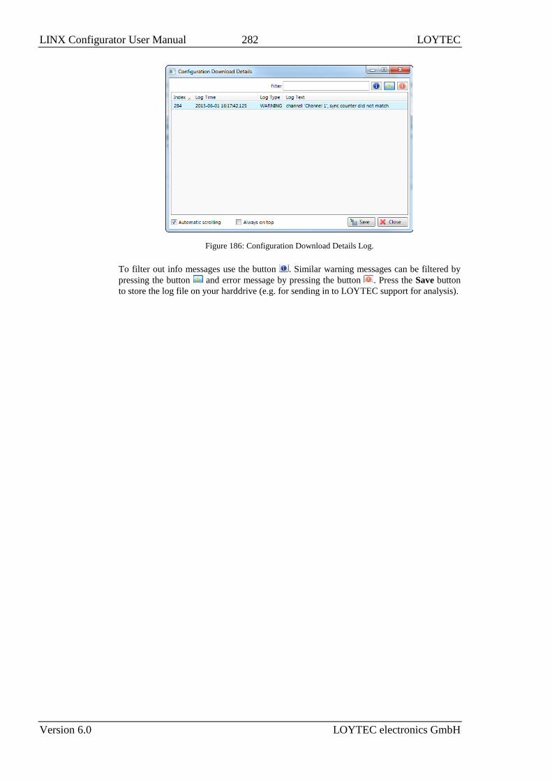
LINX Configurator User Manual 282 LOYTEC
Version 6.0 LOYTEC electronics GmbH
Figure 186: Configuration Download Details Log.
To filter out info messages use the button . Similar warning messages can be filtered by
pressing the button and error message by pressing the button . Press the Save button
to store the log file on your harddrive (e.g. for sending in to LOYTEC support for analysis).

LINX Configurator User Manual 283 LOYTEC
Version 6.0 LOYTEC electronics GmbH
15 File Formats
15.1 Data Point CSV File
The data point CSV file (.dpcsv) is the flexible format for editing data point properties and
for creation of data points from a list of data point templates. The first lines of the file must
contain a comment, starting with a hash character ‘#’ specifying a number of meta-
information. The last comment line specifies the columns used by the template CSV file:
#LOYTEC data point CSV
#creator: LOYTEC LINX Configurator 6.0 Mar 3 2016 17:26:16
#config:
#date: 2016-03-04 15:33:33
#dp_csv_ver: 1
#target: User Registers
#UID;IdPath;Name;Description;FullPath;DataType;Path;Direction;PlcIn;PlcOut
After that line any number of comment lines starting with the hash character ‘#’ are allowed.
Lines that are not comments specify a data point to be modified or created, using the
column name as the respective data point property name. The most important properties are
described in Table 11. The columns are separated by commas ‘,’ or semi-colons ‘;’.
When importing a data point CSV file, each line is evaluated whether an edit or a create
operation shall be executed. An edit is done if a value in an identifier column (UID, IdPath)
exists. That value identifies an existing data point. The remaining columns are then written
to the respective properties of the data point.
If no data point is identified, the data point is created under the specified ‘Path’ and ‘Name’.
The path is relative to the location where the import was started (i.e. if the import was
started on the folder ‘User Registers.Room1’ then the path is relative to ‘User
Registers.Room1’. For creating a data point, additional property columns must be specified,
depending on the technology. The import result will be displayed in a log file, which states
missing information.
Alternatively, a data point template file (.dptmpl) may be specified in the ‘TemplateFile’
column, which contains all the information to create a data point of a given technology (e.g.,
a BACnet server object or a user register with an alarm condition). The file paths of the
referenced data point template XML files are relative to the location of the data point
template CSV file.

LINX Configurator User Manual 284 LOYTEC
Version 6.0 LOYTEC electronics GmbH
Column Field Example Description
A UID 0x10dd This is a key column and references an existing data
point by its unique ID.
B IdPath User Registers.reg1 This is a key column and references an existing data
point by its full path.
C Path Floor1.Room101 The path under which the data point shall be created.
The path is relative to the folder on which the
import/export was executed-
D Name RoomTemp The name of the data point to be created. For structured
data points, this is the name of the top-level data point.
This name overrides the name of the template data
point.
E Description Room Temperature Optional description used in the data point. This
overrides the description in the template data point.
F PlcIn 1 Set the PLC in flag (‘1’) or clear it (‘0’) on the created
data point. This overrides the PLC setting of the
template data point. If left empty, the PLC setting of the
template data point is used. For structured data points
this setting is ignored.
G PlcOut 0 Set the PLC out flag (‘1’) or clear it (‘0’) on the created
data point. This overrides the PLC setting of the
template data point. If left empty, the PLC setting of the
template data point is used. For structured data points
this setting is ignored.
H Opc 1 Set the OPC flag (‘1’) or clear it (‘0’) on the created
data point. This overrides the OPC setting of the
template data point. If left empty, the OPC setting of the
template data point is used. For structured data points
this setting is ignored.
I Trend 1 If this field is ‘1’ the created data point is trended in a
generic trend. The user can override this decision to use
another trend technology during the import.
J Schedule 1 If this field is ‘1’ the created data point is scheduled by
a generic scheduler. The user can override this decision
to use another scheduler technology during the import.
K TemplateFile TempBACnet.dptmpl The data point is created from this data point template.
The location is relative to this CSV file.
Table 11: CSV columns of the data point template import file.
The data point CSV file may be further divided into sub-sections, which define the target
technology of the data points. A section is started with a comment line #target followed by
the data point root folder of that technology. For example, the CEA-709 section is started
by:
#target: CEA-709 Port
All data point CSV lines following this comment are destined for the CEA-709 Port folder
and its sub-folders. This is especially important, if data points of multiple technologies shall
be created by a single data point CSV file. When importing from a different root folder, all
target sections of other root folders are skipped.
15.2 CEA-709 NV Import File
Network variables can be imported to the Configurator software in a CSV file. The format
of this file is described in this section.

LINX Configurator User Manual 285 LOYTEC
Version 6.0 LOYTEC electronics GmbH
The first line of the file must contain a comment, starting with a hash character ‘#’
specifying the format version and import technology:
#dpal_csv_config;Version=1;Technology=CEA709
After that line any number of comment lines starting with the hash character ‘#’ are allowed.
Lines that are not comments specify one NV per line, using the column information as
described in Table 12. The columns are separated by commas ‘,’ or semi-colons ‘;’. Which
separator is used can be configured in the system settings (see Section 4.3.3).
Column Field Example Description
A SNVT 39 A numeric value of the SNVT (as defined in the SNVT
master list). The example value 39 represents a
SNVT_temp.
B NV index 0 The NV index in decimal notation of the NV on the
network node. Index starts at 0.
C NV selector 1 The NV selector in decimal notation of the NV on the
network node.
D NV name nvoTemp The NV programmatic name of the NV on the network
node.
E is output 1 Defines if this NV is an output on the network node. ‘1’
means the NV is an output on the network node.
F flag auth cfg 1 ‘1’ defines that authentication can be configured for this
NV on the network node.
G flag auth 0 ‘1’ defines that the NV is authenticated.
H flag priority cfg 1 ‘1’ defines that the priority can be configured for this
NV on the network node.
I flag priority 0 ‘1’ defines that the NV is using priority.
J flag service type
cfg
1 ‘1’ defines that the service type can be configured for
this NV on the network node.
K flag service ack 1 ‘1’ defines that the NV is using acknowledged service.
L flag polled 0 ‘1’ defines that the NV is using the polled attribute
M flag sync 0 ‘1’ defines that the NV is a synchronous NV.
N Deviceref 1 This field is a numeric reference to a device description.
If it is the first occurrence of this reference in the file,
the columns defined below must be filled in. Otherwise,
they can be left out.
O programID 9000A44850060402 The program ID string of the network device.
P neuronID 80000000C8C8 The NID of the network device.
Q Subnet 2 The subnet address of the network device. Use ‘0’ if the
device has no subnet address information.
R Node 3 The node address of the network device. Use ‘0’ if the
device has no node address information.
S location str 0 The location string of the network device. Use ‘0’ if no
information is available.
T Device name DDC The device name of the network device. Leave this field
blank if this information is not available.
U node self-doc &3.2@0,2 Self-documentation string of the device (special
characters are escaped)
V NV length 2 NV length in bytes
W NV self-doc @0|4 NV self-documentation string (special characters are
escaped)
Table 12: CSV Columns of the NV Import File.

LINX Configurator User Manual 286 LOYTEC
Version 6.0 LOYTEC electronics GmbH

LINX Configurator User Manual 287 LOYTEC
Version 6.0 LOYTEC electronics GmbH
16 Application Notes
16.1 The LSD Tool
Please refer to application note “AN002E LSD Tool” for further information about the
LOYTEC system diagnostics tool for the CEA-709 device models.
16.2 Use of Static, Dynamic, and External NVs on a Device
Please refer to application note “AN009E Changing Device Interface in LNS” for more
information on the static NV interface, XIF files, device templates and the use of static,
dynamic, and external NVs on LOYTEC gateway products.

LINX Configurator User Manual 288 LOYTEC
Version 6.0 LOYTEC electronics GmbH
17 References
[1] LOYTEC Device User Manual 6.0, LOYTEC electronics GmbH,
Document № 88086501, March 2016.
[2] L-IOB User Manual 6.0, LOYTEC electronics GmbH,
Document № 88080307, March 2016.
[3] L-DALI User Manual 6.0, LOYTEC electronics GmbH,
Document № 88078511, March 2016.
[4] LWEB-802/803 User Manual 2.3, LOYTEC electronics GmbH,
Document № 88074216, März 2016.
[5] LWEB-900 User Manual 2.0, LOYTEC electronics GmbH,
Document № 88081505, April 2015.
[6] L-VIS User Manual 5.1, LOYTEC electronics GmbH,
Document № 88068520, February 2015.

LINX Configurator User Manual 289 LOYTEC
Version 6.0 LOYTEC electronics GmbH
18 Revision History
Date Version Author Description
2016-03-23 6.0 STS Initial revision of the LINX Configurator User Manual.