Linux+ Guide to Linux Certification Chapter Six Linux Filesystem Administration.
Upload
truongdieuCategory
view
247download
0
Linux User Guide
Powered by:

2/26
Content
1 Linux on the DragonBoard 410c ........................................................................................................................................ 4
1.1 Known limitations .................................................................................................................................................... 4
1.2 Boot-phase status indicators.................................................................................................................................... 4
2 Installing Linux ................................................................................................................................................................... 5
2.1 Installing from SD-card ............................................................................................................................................. 5
2.2 Installing from Host-pc ............................................................................................................................................. 8
3 Recovering your DragonBoard with the rescue image .................................................................................................... 11
3.1 Installation overview .............................................................................................................................................. 11
3.2 Step1: Download the rescue image from the 96Boards website ........................................................................... 11
3.3 Step2: Copy the rescue image onto an SD-card ..................................................................................................... 11
3.4 step3: Boot the board from the SD-card ................................................................................................................ 12
4 Running Linux: First steps ................................................................................................................................................ 13
4.1 LogIn ....................................................................................................................................................................... 13
4.2 Setting up WiFi ....................................................................................................................................................... 13
5 Linux Development Environment .................................................................................................................................... 14
5.1 Toolchain ................................................................................................................................................................ 14
5.2 Eclipse Development Environment ....................................................................................................................... 15
6 Example1: HelloWorld application .................................................................................................................................. 16
6.1 Start the Eclipse IDE ............................................................................................................................................... 16
6.2 Create a new project .............................................................................................................................................. 16
6.3 Implement application ........................................................................................................................................... 18
6.4 Build and transfer the application .......................................................................................................................... 18
6.5 Execute the application .......................................................................................................................................... 18
7 Example2: BlinkyLED ........................................................................................................................................................ 20
7.1 Create a new project .............................................................................................................................................. 20
7.2 Implement application ........................................................................................................................................... 20
7.3 Build and transfer the application .......................................................................................................................... 20
7.4 Execute the application .......................................................................................................................................... 20
8 Example3: TogglyGPIO ..................................................................................................................................................... 22
8.1 Setup ...................................................................................................................................................................... 22
8.2 Create a new project .............................................................................................................................................. 22
8.3 Implement application ........................................................................................................................................... 22
8.4 Build and transfer the application .......................................................................................................................... 25

3/26
8.5 Execute the application .......................................................................................................................................... 25
9 Statements regarding FCC ............................................................................................................................................... 26
4/26
1 Linux on the DragonBoard 410c The Linux image for the Dragonboard is built by Linaro and is based on Debian with the v4.2.4 Linux Kernel (as of this writing).
1.1 Known limitations
Please see the Linaro Wiki for details regarding the known limitations of the latest Linux image:
http://builds.96boards.org/releases/dragonboard410c/linaro/debian/latest#tabs-1
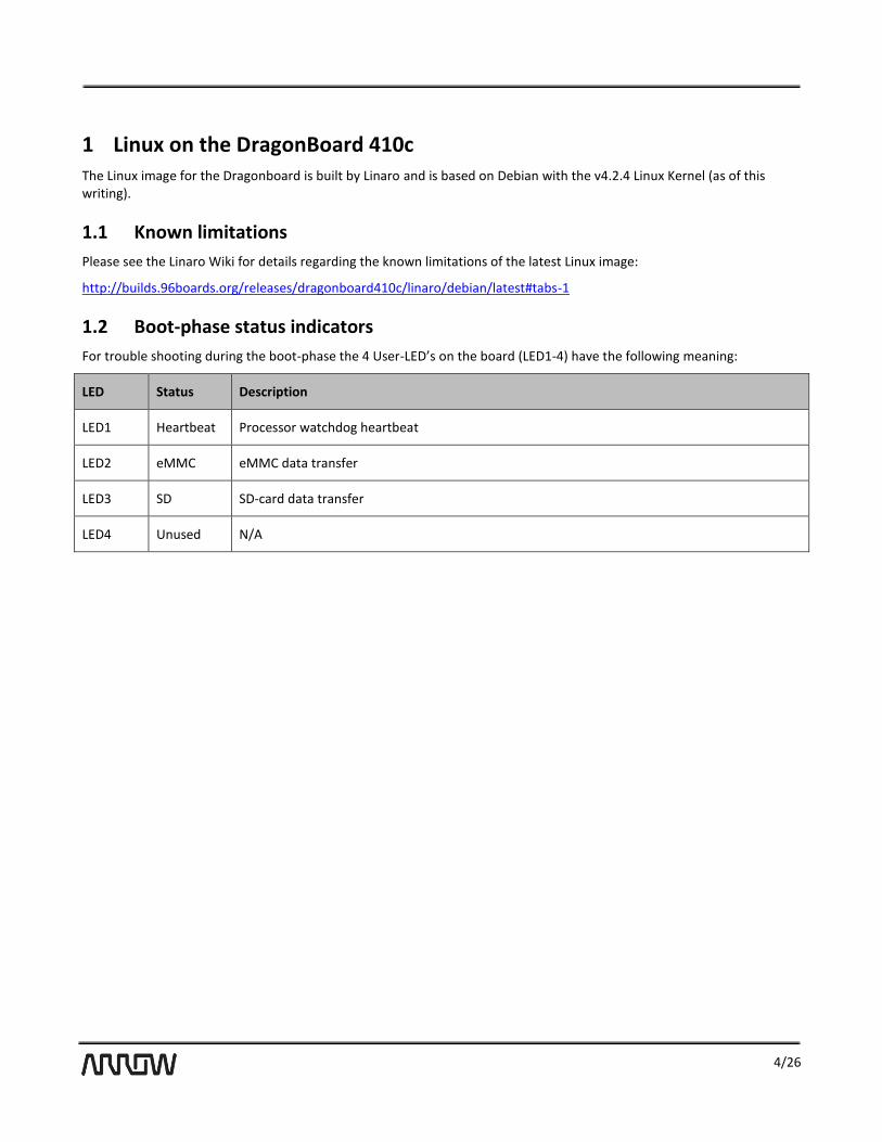
1.2 Boot-phase status indicators
For trouble shooting during the boot-phase the 4 User-LED’s on the board (LED1-4) have the following meaning:
LED Status Description
LED1 Heartbeat Processor watchdog heartbeat
LED2 eMMC eMMC data transfer
LED3 SD SD-card data transfer
LED4 Unused N/A

5/26
2 Installing Linux There are currently two supported methods to install a Linux Image on the DragonBoard410c:
Installing the image from SD-card
Installing the image from a Host computer via a USB cable and fastboot
The following chapters describe the two methods in detail.
2.1 Installing from SD-card
This is the easiest method to install Linux on the DragonBoard and is recommended for users that are just getting started with the DragonBoard.
2.1.1 Installation prerequisites
SD-card: In order to install Linux directly from SD-card you need a SD-card with at least 4GB in size.
A monitor capable of 1080p resolution. A monitor with lower resolution might not be able to display the high resolution output by the board.
Mouse and keyboard
2.1.2 Installation overview
In order to install Linux from SD-card just follow these simple steps:
Download the Installer-image from the 96-Boards Website
Write the Installer-image onto a micro SD-card
Boot the DragonBoard from the SD-card
Reboot the board and enjoy!
The following chapters describe each step in more detail:
2.1.3 Step1: Download the Installer-image from the 96-Boards Website
Image name Website link
dragonboard410c_sd_card_install_debian.zip
http://builds.96boards.org/releases/dragonboard410c/linaro/debian/latest/dragonboard410c_sdcard_install_debian-*.zip

6/26
2.1.4 Step2: Write the Installer-image onto a micro SD-card
Write the Installer image onto the SD-card using your favorite imaging tool:
On Windows:
On Linux:
Execute the following commands:
2.1.5 Step3: Boot the DragonBoard from the SD-card
● Plug In the programmed SD-card into the board
● Connect a Mouse and Keyboard to the board
● Connect a monitor with an HDMI cable to the board
● Set the boot switches S6 to 0100 (boot from SD-card)
● Plug the power supply into the board
● The board should start up and show a Dialog from which you can choose the Operating System to install
Download the Win32DiskImager tool from here
Start the DiskImager tool
Under Image file select the path to the image
Under Device choose the drive letter under which the sd-card was detected
Click Write -> This will write the image onto the micro sd-card
sudo dd if=db410_sd_install_linux.img of=/dev/XXX bs=2M sync
Where XXX is the device name
Warning: Do not override your hard drive. In most cases, XXX will be mmcblk0 or sdx where x depends on the number of fixed disks in your system. You can determine the sd-cards device name by using the following command:
sudo fdisk -l

7/26
● Choose the displayed Operating system (Linaro Linux) and click Install. This will flash the OS on the board eMMC
● Once you see the programming successful dialog proceed with the next step
2.1.6 Step4: Reboot and enjoy!
● unplug the power cord
● remove the SD-card
● reset the boot switches to 0000
● Plug in the power cord. The system should now boot into your chosen Operating System

8/26
2.2 Installing from Host-pc
This method is recommended for experienced users who will be downloading many iterative experimental versions of self-compiled OS’s. It is also a fallback method in case the first method fails because either the monitor or mouse and keyboard could not be detected. Since this method uses a HostPC to program the board a separate monitor and mouse/keyboard do not need to be connected to the board.
This guide describes the process both for Windows and Linux Host systems.
2.2.1 Installation prerequisites
Fastboot: This method requires the Fastboot tool to be installed on the HostPC. Fastboot is a tool that communicates with the bootloader of the DragonBoard 410c and allows you to flash images onto the board. See below for instruction on how to install Fastboot on your Host PC.
Install fastboot on your Host PC:
Download and install the fastboot tool on to your Host PC:
On Windows Host:
Google currently does not offer a standalone Windows Installer for fastboot. Instead it provides fastboot only as part of the full Android Studio development environment installation. If you want to install fastboot without the full Android Studio installation you can find third party installers on the web site.
On Linux Host (Ubuntu/Debian):
Execute the following command:
sudo apt-get install android-tools-fastboot
2.2.2 Installation overview
In order to install Linux from a Host PC just follow these simple steps:
step 1. Download the Linux images from the 96Boards Website step 2. Bring the board into fastboot-mode step 3. Start the fastboot tool on the HostPC step 4. Flash the Bootloader Image step 5. Flash the boot image step 6. Flash the rootfs image step 7. Reboot and enjoy
The following chapters describe each step in more detail:
2.2.3 Step1: Download the Linux images from the 96Boards Website
Download the following images from the 96Boards website:
Image Filename Link
Bootloader image
dragonboard410c_bootloader_emmc_linux.zip
http://builds.96boards.org/releases/dragonboard410c/linaro/rescue/latest/dragonboard410c_bootloader_emmc_linux*.zip
boot image boot-linaro-jessie-qcom-snapdragon-arm64.img.gz
http://builds.96boards.org/releases/dragonboard410c/linaro/debian/latest/boot-linaro-jessie-qcom-snapdragon-arm64-*.img.gz

9/26
Rootfs image
linaro-jessie-alip-qcom-snapdragon-arm64.img.gz
http://builds.96boards.org/releases/dragonboard410c/linaro/debian/latest/linaro-jessie-alip-qcom-snapdragon-arm64-*.img.gz
2.2.4 Step2: Bring the board into fastboot-mode
● Ensure the boot switches S6 are set to 0000 ● Connect the micro-usb cable to the board ● Press and hold the Vol- button (S4) ● Connect the power supply to the board
2.2.5 Step3: Start the fastboot tool on the HostPC
Start the fastboot application on the host PC and execute the following fastboot command. You should see your board
listed:
fastboot devices
Please note: If you run Fastboot from a Linux HostPC you might have to run it with sudo privileges.
For example: sudo fastboot devices
2.2.6 Step4: Flash the bootloader-image
Extract the Bootloader image: unzip dragonboard410c_bootloader_emmc_linux-BB.zip
Then flash the Bootloader-image files via fastboot**: fastboot flash partition gpt_both0.bin
fastboot flash hyp hyp.mbn
fastboot flash modem NON-HLOS.bin
fastboot flash rpm rpm.mbn
fastboot flash sbl1 sbl1.mbn
fastboot flash sec sec.dat
fastboot flash tz tz.mbn
fastboot flash aboot emmc_appsboot.mbn
fastboot erase boot
fastboot erase rootfs
fastboot erase devinfo
** If you use fastboot on a Linux HostPC you might have to execute fastboot with sudo privileges. For example: sudo fastboot flash partition gpt_both0.bin
2.2.7 Step5: Flash the boot-image
Extract the boot-image:
tar xz boot-linaro-jessie-qcom-snapdragon-arm64-YYYYMMDD-UU.img.gz
Then flash the boot-image into the boot partition of the board via fastboot**: fastboot flash boot boot-linaro-jessie-qcom-snapdragon-arm64-YYYYMMDD-UU.img
2.2.8 Step6: Flash the rootfs-image
Extract the rootfs-image: Tar xz linaro-jessie-alip-qcom-snapdragon-arm64-YYYYMMDD-UU.img.gz
Then flash the rootfs-image into the rootfs partition of the board via fastboot**: fastboot flash rootfs linaro-jessie-alip-qcom-snapdragon-arm64-YYYYMMDD-UU.img

10/26
2.2.9 Step7: Reboot and enjoy!
Once the download of the images is complete, follow these steps:
● Unplug the board from the power supply ● Disconnect the USB cable ● Reset the boot switches back to 0000 ● Connect the board to the power supply
After the reboot you should see Linux startup.

11/26
3 Recovering your DragonBoard with the rescue image Use this method if the previous two method failed and you were not able to reach the board via the fastboot tool. (fastboot devices command not listing your device.)
3.1 Installation overview
To recover your board from the rescue-image, follow these steps:
step 1. Download rescue image from the 96Boards website step 2. Copy the rescue image on a SD-card step 3. Boot the board from the SD-card
3.2 Step1: Download the rescue image from the 96Boards website
Download and extract the Recovery image from the 96Boards website:
Image name Website link
dragonboard410c_sd_card_rescue.zip
http://builds.96boards.org/releases/dragonboard410c/linaro/rescue/latest/dragonboard410c_sdcard_rescue*.zip
3.3 Step2: Copy the rescue image onto an SD-card
On Windows:
● Download the Win32DiskImager tool from here ● Start the DiskImager tool
● Under Image file select the path to the rescue-image
● Under Device choose the drive letter under which the SD-card was detected
● Click Write -> This will write the image onto the micro SD-card
On Linux:
Execute the following commands:
dd if=db410c_sd_rescue.img of=/dev/XXX bs=2M
sync
Where XXX is the device name
Warning: Do not override your hard drive. In most cases, XXX will be mmcblk0 or sdx where x depends on the number of fixed disks in your system. You can determine the SD-cards device name by using the following command:

12/26
sudo fdisk -l
Alternatively you can also use the following command to determine the SD-card device name:
dmesg | tail
3.4 step3: Boot the board from the SD-card
● Put the SD-card into your DragonBoard ● Set the boot switches S6 to 0100 (SD-card boot) ● Plug in the power cord -> the board should startup into fastboot mode and you should be able to reach the board
from the Host via the fastboot tool.
With fastboot up and running again you can now follow the usual procedure and flash you preferred OS as described in chapter 2.2 step 1-7.

13/26
4 Running Linux: First steps While it would go beyond the scope of this user guide to go into all aspects of running Linux, in this chapter we will go over some of the most common use cases relevant to get started with the board.
4.1 LogIn
The Debian Image is setup to login automatically with the “linaro” account. The account credentials are as follows:
User: linaro password: linaro
4.2 Setting up WiFi
After logging in, select the Network-Icon located at the lower right corner of the desktop . You should be presented with a list of available networks.
Choose the network that you wish to connect to and provide the network password. The board will establish the connection and after a few seconds you should see the network icon change to the following icon:

14/26
5 Linux Development Environment The following picture depicts the typical development setup for the DragonBoard 410c:
For this Guide we assume a HostPC with Linux operating system as development machine. However development is also possible on a HostPC with another operating system such as Microsoft Windows or Apple MacOS.
5.1 Toolchain
In order to build your own Linux applications for the DragonBoard you need a cross-development toolchain.
A toolchain consists of the following elements:
● Assembler ● Compiler ● Linker ● Debugger ● Runtime Libraries ● Utilities
The term “cross“-development toolchain refers to the toolchain being capable of running on a Host PC with architecture X but producing binaries for a target with Architecture Y.
There are several toolchains available however for this guide we use the Linaro toolchain.
You can get the Linaro toolchain from the following website:
For 32bit Linux Host http://releases.linaro.org/14.11/components/toolchain/binaries/arm-linux-gnueabihf/gcc-linaro-4.9-2014.11-x86_64_arm-linux-gnueabihf.tar.xz
For 64bit Linux Host http://releases.linaro.org/14.11/components/toolchain/binaries/aarch64-linux-gnu/gcc-linaro-4.9-2014.11-x86_64_aarch64-linux-gnu.tar.xz

15/26
5.1.1 Installing the toolchain
In order to install the toolchain unpack the downloaded toolchain file in a folder of your choice. For instance for the 64bit toolchain type the following:
~/DragonBoard/toolchain/:
tar xz gcc-linaro-4.9-2014.11-x86_64_aarch64-linux-gnu.tar.xz
5.2 Eclipse Development Environment
Eclipse is a free and open source Integrated Development environment that is highly customizable through a flexible plugin system.
5.2.1 Installing Eclipse
You can download Eclipse from the following website:
For 32bit Host: http://www.eclipse.org/downloads/download.php?file=/technology/epp/downloads/release/luna/SR2/eclipse-cpp-luna-SR2-linux-gtk.tar.gz
For 64bit Host: http://www.eclipse.org/downloads/download.php?file=/technology/epp/downloads/release/luna/SR2/eclipse-cpp-luna-SR2-linux-gtk-x86_64.tar.gz
Copy the downloaded file to a location of your choice and extract it.
For example:
~/DragonBoard/ide/
tar xz eclipse-cpp-luna-SR2-linux-gtk-x86_64.tar.gz

16/26
6 Example1: HelloWorld application With the Eclipse IDE and the toolchain installed we can now develop our fist Hello World application for the DragonBoard 410c.
The following example is assuming a Linux based host development machine.
6.1 Start the Eclipse IDE
To start the eclipse IDE switch to the eclipse installation folder and type the following command on a command line:
./eclipse
This will start the eclipse IDE. If you start Eclipse for the first time, Eclipse might ask you to choose the location of the project workspace. Choose your preferred Workspace location or just accept the default by pressing OK. if you see a welcome screen just close it by pressing the x-symbol on the top left corner of the screen. You should now see the actual IDE surface.
6.2 Create a new project
Once the IDE is up and running, create a new project by selecting from the menu bar: File->New->C Project.
On the C Project Dialog:
In the Project type field choose: “Hello World ANSI C Project”-template
In the Project name field type the project name : “HelloDragonBoard”
In the Toolchains field select: Cross GCC
Click Next

17/26
On the Basic settings Dialog:
Click next.
On the configuration Dialog:
Click next.
On the Cross GCC Command dialog :
Set cross compiler prefix to : aarch64-linux-gnu-
Set the cross compiler path to the /bin directory of the toolchain: <toolchain installation path>/bin
Click Finish
Once you click finish the project wizard will create the project for you:

18/26
6.3 Implement application
The project template contains a basic Hello World implementation that will compile and run on the board. Feel free to change the default “!!!Hello World!!!” message that is outputted on line 15 to “!!! Hello DragonBoard410c !!!”.
6.4 Build and transfer the application
Click the hammer at the top of the screen to build the Debug configuration. This will create an executable binary file located in the projects debug directory. Copy the generated HelloDragonBoard executable to a flash drive and then, on the DragonBoard, copy it to a simple location such as the user directory (~).
6.5 Execute the application
Before the application can be executed we need to change the permissions of the applications binary file to allow it to be executed. To do this run the following command:

19/26
chmod u+x HelloDragonBoard
The application can now be executed by running the command:
./HelloDragonBoard
You should see the “!!! Hello DragonBoard410c !!!” message output to the command line.

20/26
7 Example2: BlinkyLED In this example we will access the hardware of the DragonBoard410c by toggling one of the User-LED’s on the board.
7.1 Create a new project
Create a new project as described in chapter 6.2 and name the project BlinkyLED.
7.2 Implement application
Replace the code in the BlinkyLED.c file with the code shown below.
/*
============================================================================
Name : BlinkyLED.c
Author :
Version :
Copyright : Your copyright notice
Description : Simple Hardware access example that blinks user-LED4
============================================================================
*/
#include <stdlib.h>
#include <stdio.h>
#include <fcntl.h>
#include <unistd.h>
//defining the path to the file in the filesystem that controls the LED
#define LED4 "/sys/class/leds/apq8016-sbc\:green\:user3/brightness"
int main( void )
{
//opening the brightness-file
int led4_fd = open( LED4, O_WRONLY);
if(led4_fd < 0)
{
printf("Could not open File: %s", LED4);
return 0;
}
int i;
for( i=0; i<10;i++)
{
//Blinky code
write( led4_fd, "1", 2 ); //Turning the LED ON by writing 1 into the brightness file
sleep( 1 );
write( led4_fd, "0", 2 ); //Turning the LED OFF by writing 0 into the brightness file
sleep( 1 );
}
close(led4_fd);
}
7.3 Build and transfer the application
Click the hammer at the top of the screen to build the Debug configuration. This will create an executable binary file located in the projects debug directory. Copy the generated executable to a flash drive and then, on the DragonBoard, copy it to a simple location such as the user directory (~).
7.4 Execute the application

21/26
Before the application can be executed we need to change the permissions of the applications binary file to allow it to be executed. To do this run the following command:
chmod u+x BlinkyLED
Since the application accesses the hardware it requires elevated privileges and needs to be executed using the sudo command:
sudo ./BlinkyLED
You should see the User_led4 blinking.
22/26
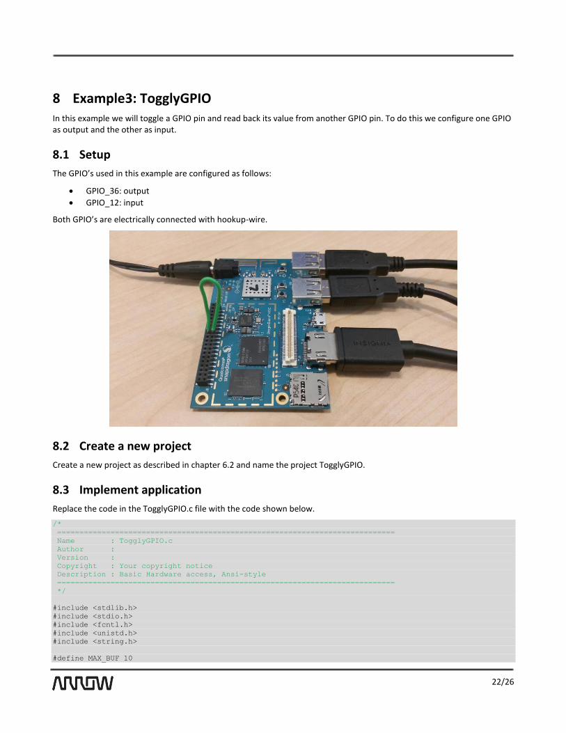
8 Example3: TogglyGPIO In this example we will toggle a GPIO pin and read back its value from another GPIO pin. To do this we configure one GPIO as output and the other as input.
8.1 Setup
The GPIO’s used in this example are configured as follows:
GPIO_36: output
GPIO_12: input
Both GPIO’s are electrically connected with hookup-wire.
8.2 Create a new project
Create a new project as described in chapter 6.2 and name the project TogglyGPIO.
8.3 Implement application
Replace the code in the TogglyGPIO.c file with the code shown below.
/*
============================================================================
Name : TogglyGPIO.c
Author :
Version :
Copyright : Your copyright notice
Description : Basic Hardware access, Ansi-style
============================================================================
*/
#include <stdlib.h>
#include <stdio.h>
#include <fcntl.h>
#include <unistd.h>
#include <string.h>
#define MAX_BUF 10

23/26
#define GPIO_A 36
#define GPIO_B 12
int Export_GPIO(int gpio);
int UnExport_GPIO(int gpio);
int Write_GPIO(int gpio, int value);
int Read_GPIO(int gpio, int *value);
int main(void)
{
char c=' ';
int ret;
int out_value = 1;
int in_value = 0;
//
//exporting GPIO’s
//
ret = Export_GPIO(GPIO_A);
if(ret != 0)
printf("Error exporting GPIO_%d", GPIO_A);
ret = Export_GPIO(GPIO_B);
if(ret != 0)
printf("Error exporting GPIO_%d", GPIO_B);
//
//writing/reading GPIO’s
//
printf("press any key to toggle GPIO_A or 'q' to quit:\n");
while(c != 'q')
{
printf("Writing GPIO_%d: value=%d \n", GPIO_A, out_value);
ret = Write_GPIO(GPIO_A, out_value);
if (ret != 0)
printf("Error writing GPIO_%d", GPIO_A);
ret = Read_GPIO(GPIO_B, (int*) &in_value);
if (ret != 0)
printf("Error reading GPIO_%d", GPIO_B);
printf("Reading GPIO_%d: value=%d \n", GPIO_B, in_value);
out_value = !out_value;
c= getchar();
}
//
//UnExporting GPIO’s
//
ret = UnExport_GPIO(GPIO_A);
if(ret != 0)
printf("Error UnExporting GPIO_%d", GPIO_A);
ret = UnExport_GPIO(GPIO_B);
if(ret != 0)
printf("Error UnExporting GPIO_%d", GPIO_B);
return 0;
}
int Export_GPIO(int gpio)
{
int fd;
char buf[MAX_BUF];
//Export the specific GPIO
//this will create a new folder with the gpio name

24/26
sprintf(buf, "%d", gpio);
fd = open("/sys/class/gpio/export", O_WRONLY);
if(fd < 0)
return -1;
write(fd, buf, strlen(buf));
close(fd);
return 0;
}
int UnExport_GPIO(int gpio)
{
int fd;
char buf[MAX_BUF];
sprintf(buf, "%d", gpio);
fd = open("/sys/class/gpio/unexport", O_WRONLY);
if(fd < 0)
return -1;
write(fd, buf, strlen(buf));
close(fd);
return 0;
}
int Write_GPIO(int gpio, int value)
{
int fd;
char buf[MAX_BUF];
//Set the direction of the GPIO to output
sprintf(buf, "/sys/class/gpio/gpio%d/direction", gpio);
fd = open(buf, O_WRONLY);
if(fd<0)
return -1;
write(fd, "out", 3);// Set out direction
close(fd);
sprintf(buf, "/sys/class/gpio/gpio%d/value", gpio);
fd = open(buf, O_WRONLY);
if(fd<0)
return -1;
// Write the GPIO value
sprintf(buf, "%d", value);
write(fd, buf, strlen(buf));
close(fd);
return 0;
}
int Read_GPIO(int gpio, int *value)
{
int fd;
char val;
char buf[MAX_BUF];
sprintf(buf, "/sys/class/gpio/gpio%d/value", gpio);
fd = open(buf, O_RDONLY);
if(fd<0)
return -1;
// Read the GPIO value
read(fd, &val, 1);
*value = atoi(&val);
close(fd);
return 0;
}

25/26
8.4 Build and transfer the application
Click the hammer at the top of the screen to build the Debug configuration. This will create an executable binary file located in the projects debug directory. Copy the generated executable to a flash drive and then, on the DragonBoard, copy it to a simple location such as the user directory (~).
8.5 Execute the application
Before the application can be executed we need to change the permissions of the applications binary file to allow it to be executed. To do this run the following command:
chmod u+x TogglyGPIO
Since the application accesses the hardware it requires elevated privileges and needs to be executed using the sudo command:
sudo ./TogglyGPIO
You should see the following output:

26/26
9 Statements regarding FCC FCC Label Warning
This device complies with Part 15 of the FCC Rules. Operation is subject to the following two conditions:
This device may not cause harmful interference.
This device must accept any interference received, including interference that may cause undesired operation.
Cet appareil se conforme aux principes de licence –exempts RSS de l’Industrie de Canada. Gestion dépende des conditions suivantes :
l'appareil ne doit pas produire de l’interférence, et
l'appareil doit accepter toutes sortes d’interférences, cela incluet l’interférence qui va peut--‐être causer les résultats indésirables de l’appareil.
This device generates and uses radio waves and if not used properly may cause interference to radio and TV reception. It has been tested and found to comply with the limits set by the FCC which are designed to provide reasonable protection against such interference.
CAUTION
Arrow Electronics, Inc. (“Arrow”) is not responsible for any radio or TV interference caused by unauthorized modifications to this equipment. Changes or modifications not expressly approved Arrow could void the user’s authority to operate the equipment.
FCC Warning Statement
Note: This equipment has been tested and found to comply with the limits for a Class B digital device, pursuant to Part 15 of the FCC Rules. These limits are designed to provide reasonable protection against harmful interference in a residential installation. This equipment generates uses and can radiate radio frequency energy and, if not installed and used in accordance with the instructions, may cause harmful interference to radio communications. However, there is no guarantee that interference will not occur in a particular installation. If this equipment does cause harmful interference to radio or television reception, which can be determined by turning the equipment off and on, the user is encouraged to try to correct the interference by one or more of the following measures:
Reorient or relocate the receiving antenna.
Increase the separation between the equipment and receiver.
Connect the equipment into an outlet on a circuit different from that to which the receiver is connected.
Consult the dealer or an experienced radio/television technician for help.
CAN ICES-3 (B) / NMB-3 (B)
This equipment complies with radiation exposure limits set forth for uncontrolled environment. The antenna(s) used for this transmitter must be installed to provide a separation distance of at least 20 cm from all persons and must not be collocated or operating in conjunction with any other antenna or transmitter.
Cet appareil se conforme aux limites d'exposition aux rayonnements pour un environnement non contrôlé. L'antenne (s) qui est utilize pour cet émetteur doit être installé pour produire une distance de separation d'au moins 20 cm de toutes personnes et ne doit pas être installé à proximité ou utilize en conjunction avec une autre antenne ou émetteur.