Link Layer. 2 Content Error detection and correction MAC sub-layer Ethernet Token Ring.
92
Link Layer
-
Upload
erick-pope -
Category
Documents
-
view
239 -
download
0
Transcript of Link Layer. 2 Content Error detection and correction MAC sub-layer Ethernet Token Ring.
Link Layer
2
Content
Error detection and correction MAC sub-layer Ethernet Token Ring
3
Access Protocols
Who gets to use the channel next? Fixed/Static assignment Demand assignment Contention Turn-Based
4
Contention Access Protocols
No coordination between hosts Control is completely distributed Outcome is probabilistic Examples: ALOHA, CSMA, CSMA/CD
5
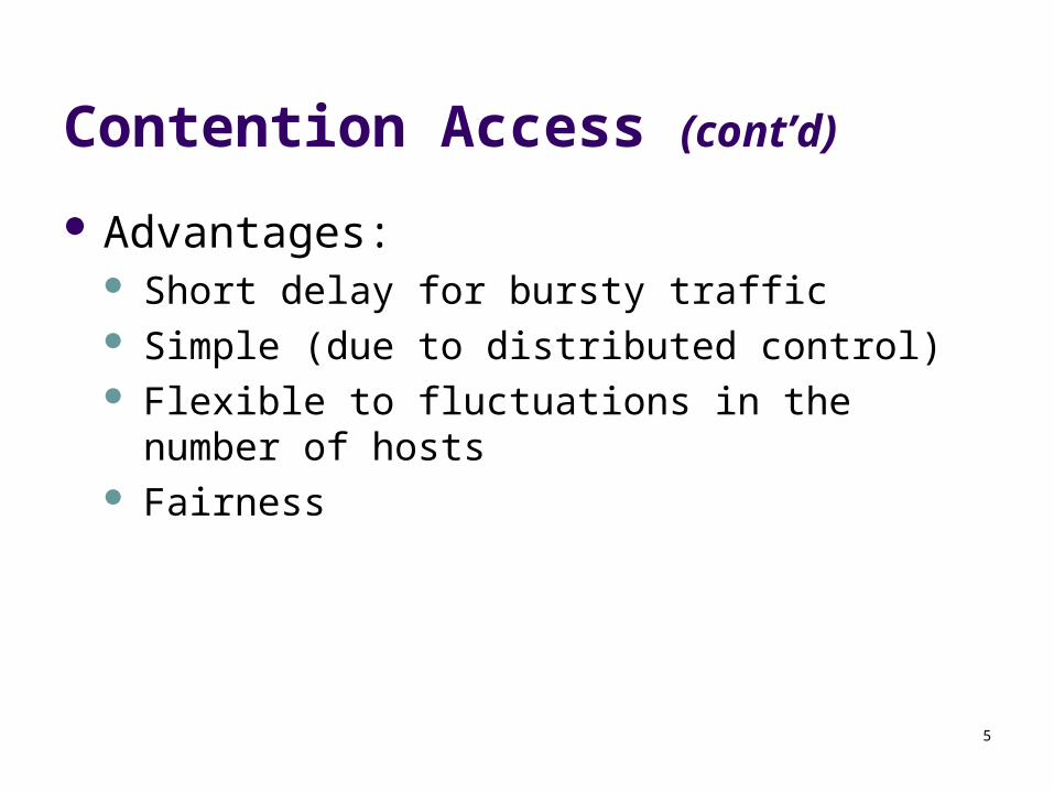
Contention Access (cont’d)
Advantages: Short delay for bursty traffic Simple (due to distributed control) Flexible to fluctuations in the number of hosts Fairness
6
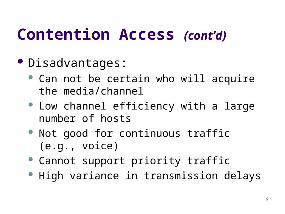
Contention Access (cont’d)
Disadvantages: Can not be certain who will acquire the
media/channel Low channel efficiency with a large number of
hosts Not good for continuous traffic (e.g., voice) Cannot support priority traffic High variance in transmission delays
7
Contention Access Methods
Pure ALOHA Slotted ALOHA CSMA
1-Persistent CSMA Non-Persistent CSMA P-Persistent CSMA
CSMA/CD
8
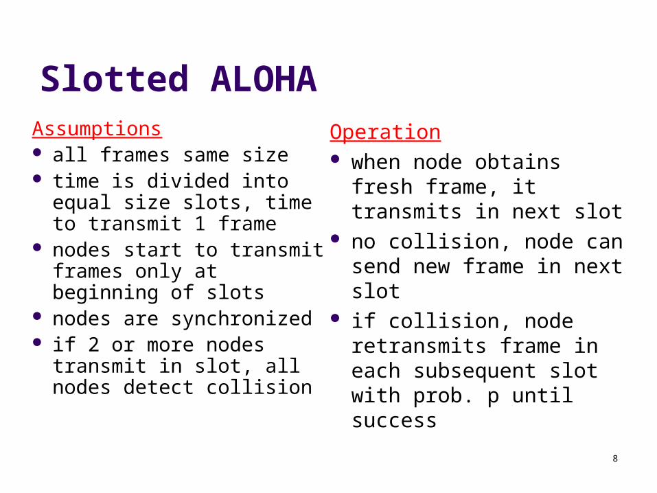
Slotted ALOHAAssumptions all frames same size time is divided into equal
size slots, time to transmit 1 frame
nodes start to transmit frames only at beginning of slots
nodes are synchronized if 2 or more nodes
transmit in slot, all nodes detect collision
Operation when node obtains fresh
frame, it transmits in next slot
no collision, node can send new frame in next slot
if collision, node retransmits frame in each subsequent slot with prob. p until success
9
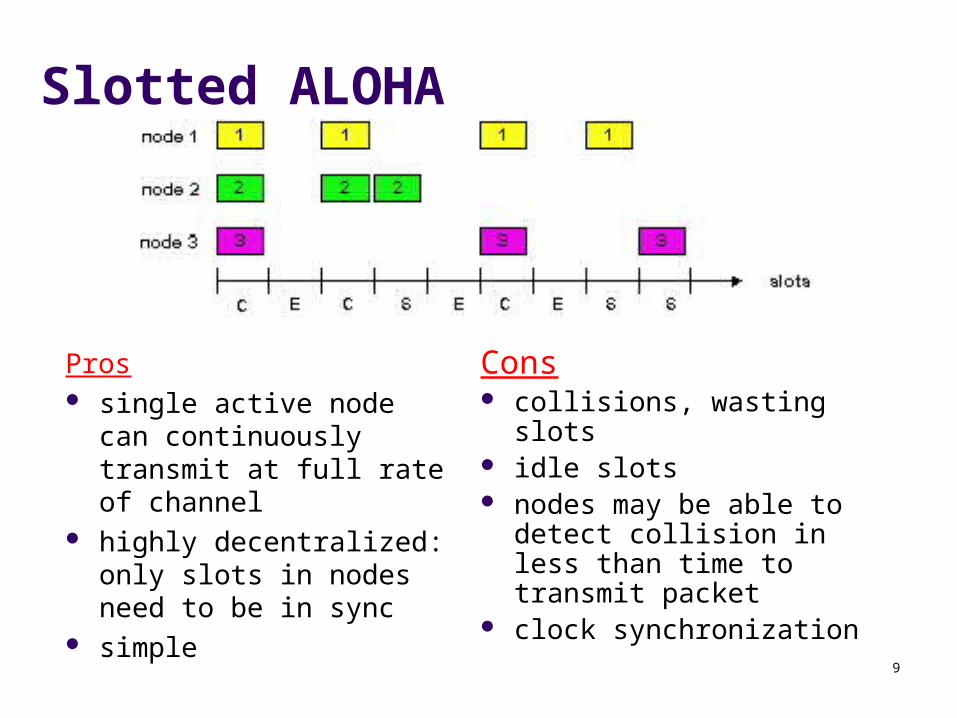
Slotted ALOHA
Pros single active node can
continuously transmit at full rate of channel
highly decentralized: only slots in nodes need to be in sync
simple
Cons collisions, wasting slots idle slots nodes may be able to
detect collision in less than time to transmit packet
clock synchronization
10
Slotted Aloha efficiency
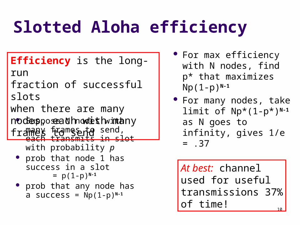
Suppose N nodes with many frames to send, each transmits in slot with probability p
prob that node 1 has success in a slot = p(1-p)N-1
prob that any node has a success = Np(1-p)N-1
For max efficiency with N nodes, find p* that maximizes Np(1-p)N-1
For many nodes, take limit of Np*(1-p*)N-1 as N goes to infinity, gives 1/e = .37
Efficiency is the long-run fraction of successful slots when there are many nodes, each with many frames to send
At best: channelused for useful transmissions 37%of time!
11
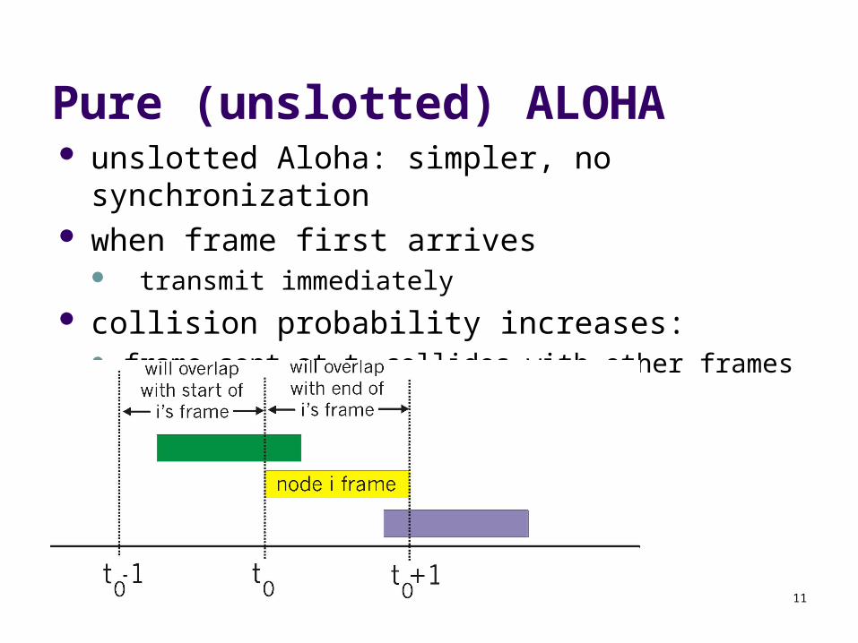
Pure (unslotted) ALOHA unslotted Aloha: simpler, no synchronization when frame first arrives
transmit immediately
collision probability increases: frame sent at t0 collides with other frames sent in [t0-1,t0+1]
12
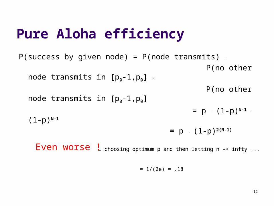
Pure Aloha efficiency
P(success by given node) = P(node transmits) .
P(no other node transmits in [p0-1,p0] .
P(no other node transmits in [p0-1,p0]
= p . (1-p)N-1 . (1-p)N-1
= p . (1-p)2(N-1)
… choosing optimum p and then letting n -> infty ...
= 1/(2e) = .18 Even worse !
13
Carrier Sense Multiple Access (CSMA)
We could achieve better throughput if we could listen to the channel before transmitting a packet
This way, we would stop avoidable collisions. To do this, we need “Carrier Sense Multiple
Access,” or CSMA, protocols
14
Assumptions with CSMA Networks
1. Constant length packets
2. No errors, except those caused by collisions
3. No capture effect
4. Each host can sense the transmissions of all other hosts
5. The propagation delay is small compared to the transmission time
15
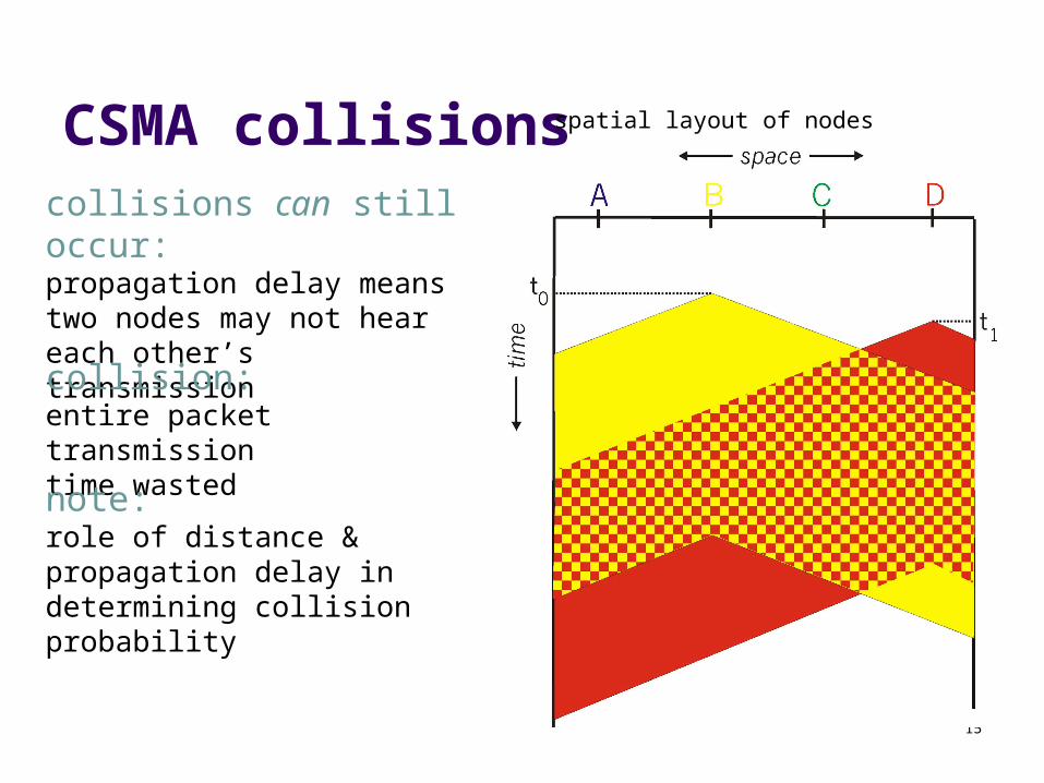
CSMA collisionscollisions can still occur:propagation delay means two nodes may not heareach other’s transmissioncollision:entire packet transmission time wasted
spatial layout of nodes
note:role of distance & propagation delay in determining collision probability
16
CSMA (cont’d)
There are several types of CSMA protocols: 1-Persistent CSMA Non-Persistent CSMA P-Persistent CSMA
17
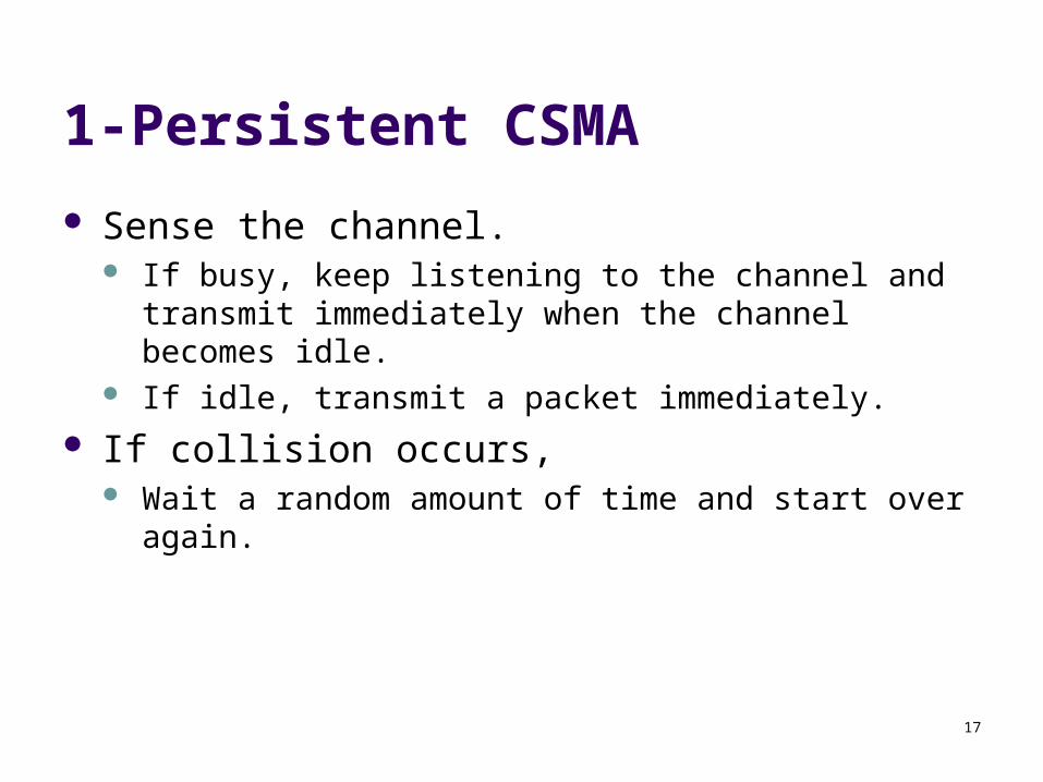
1-Persistent CSMA
Sense the channel. If busy, keep listening to the channel and transmit
immediately when the channel becomes idle. If idle, transmit a packet immediately.
If collision occurs, Wait a random amount of time and start over again.
18
1-Persistent CSMA (cont’d)
The protocol is called 1-persistent because the host transmits with a probability of 1 whenever it finds the channel idle.
19
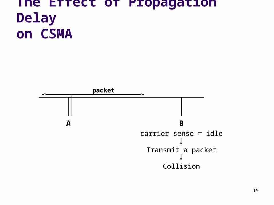
The Effect of Propagation Delayon CSMA
A Bcarrier sense = idle
Transmit a packet
Collision
packet
20
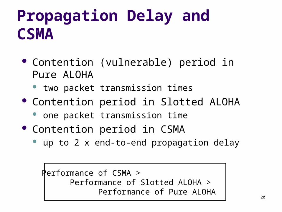
Propagation Delay and CSMA
Contention (vulnerable) period in Pure ALOHA two packet transmission times
Contention period in Slotted ALOHA one packet transmission time
Contention period in CSMA up to 2 x end-to-end propagation delay
Performance of CSMA > Performance of Slotted ALOHA >
Performance of Pure ALOHA
21
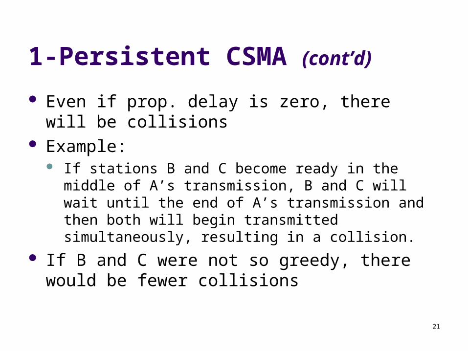
1-Persistent CSMA (cont’d)
Even if prop. delay is zero, there will be collisions Example:
If stations B and C become ready in the middle of A’s transmission, B and C will wait until the end of A’s transmission and then both will begin transmitted simultaneously, resulting in a collision.
If B and C were not so greedy, there would be fewer collisions
22
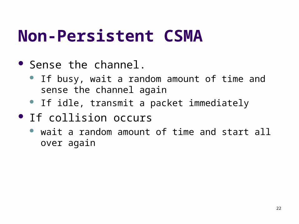
Non-Persistent CSMA
Sense the channel. If busy, wait a random amount of time and sense the
channel again If idle, transmit a packet immediately
If collision occurs wait a random amount of time and start all over again
23
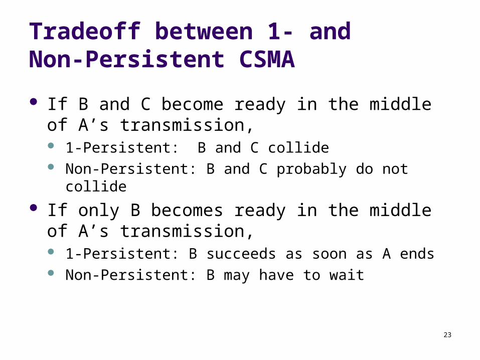
Tradeoff between 1- and Non-Persistent CSMA
If B and C become ready in the middle of A’s transmission, 1-Persistent: B and C collide Non-Persistent: B and C probably do not collide
If only B becomes ready in the middle of A’s transmission, 1-Persistent: B succeeds as soon as A ends Non-Persistent: B may have to wait
24
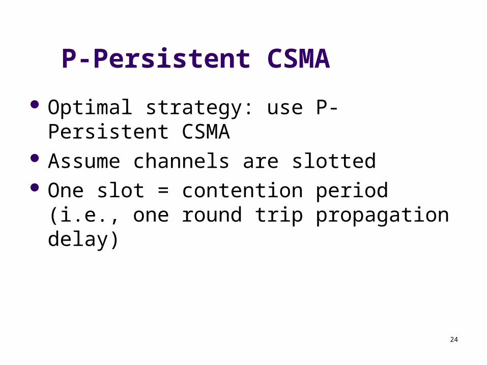
P-Persistent CSMA
Optimal strategy: use P-Persistent CSMA Assume channels are slotted One slot = contention period (i.e., one round
trip propagation delay)
25
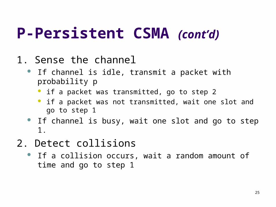
P-Persistent CSMA (cont’d)
1. Sense the channel If channel is idle, transmit a packet with probability p
if a packet was transmitted, go to step 2 if a packet was not transmitted, wait one slot and go to step 1
If channel is busy, wait one slot and go to step 1.
2. Detect collisions If a collision occurs, wait a random amount of time and go to step
1
26
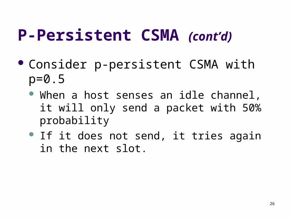
P-Persistent CSMA (cont’d)
Consider p-persistent CSMA with p=0.5 When a host senses an idle channel, it will only
send a packet with 50% probability If it does not send, it tries again in the next slot.
27
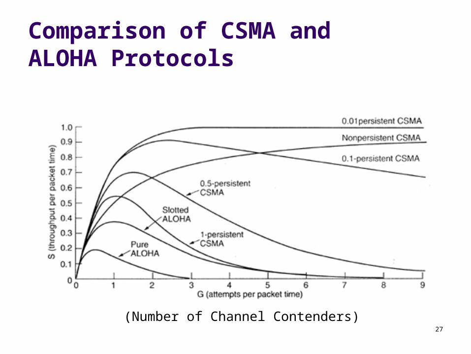
Comparison of CSMA and ALOHA Protocols
(Number of Channel Contenders)
28
CSMA/CD
In CSMA protocols If two stations begin transmitting at the same time, each
will transmit its complete packet, thus wasting the channel for an entire packet time
In CSMA/CD protocols The transmission is terminated immediately upon the
detection of a collision CD = Collision Detect
29
CSMA/CD (Collision Detection)
collision detection: easy in wired LANs: measure signal strengths,
compare transmitted, received signals difficult in wireless LANs: receiver shut off while
transmitting
human analogy: the polite conversationalist
30
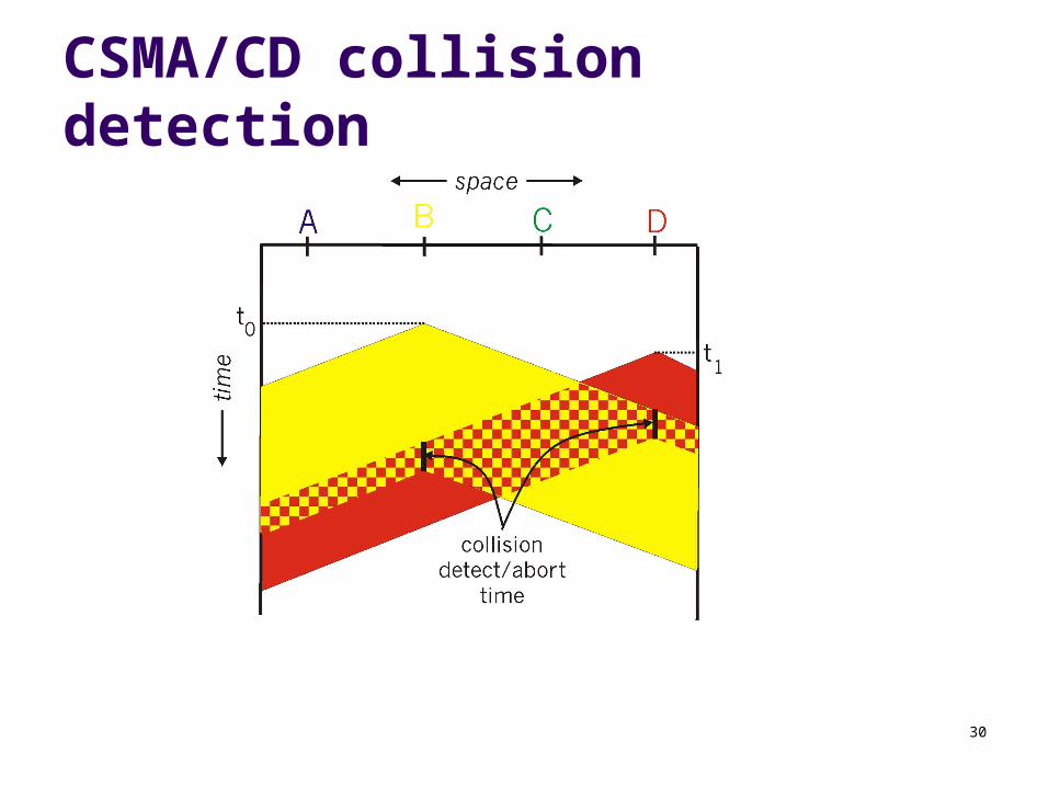
CSMA/CD collision detection
31
CSMA/CD
Sense the channel If idle, transmit immediately If busy, wait until the channel becomes idle
Collision detection Abort a transmission immediately if a collision is detected Try again later after waiting a random amount of time
32
CSMA/CD (cont’d)
Carrier sense reduces the number of collisions
Collision detection reduces the effect of collisions, making the
channel ready to use sooner
33
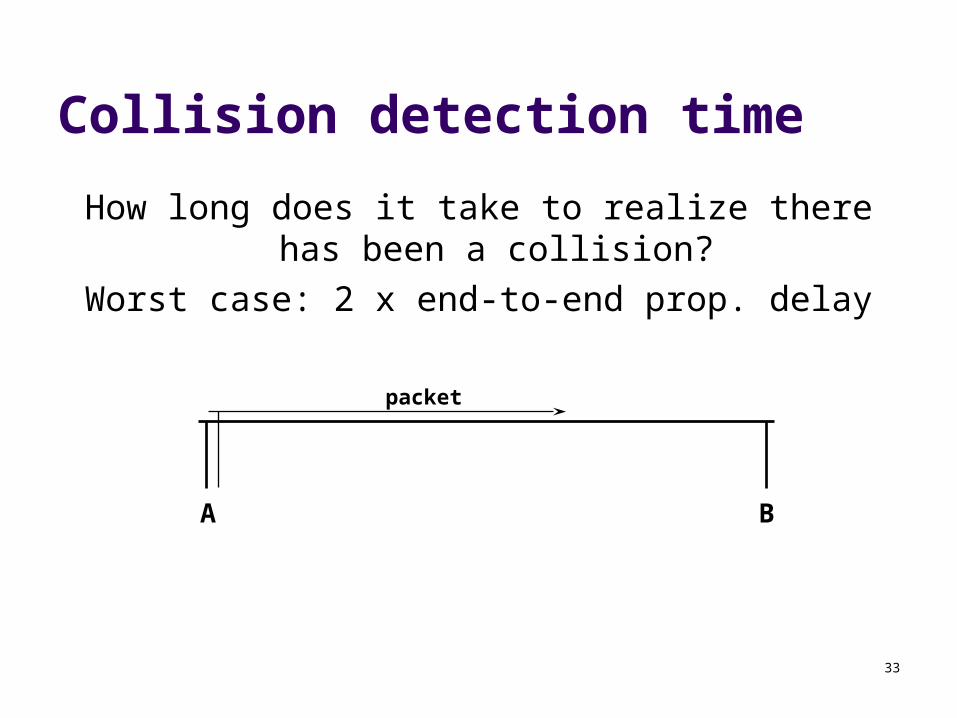
Collision detection time
How long does it take to realize there has been a collision?
Worst case: 2 x end-to-end prop. delay
A B
packet
34
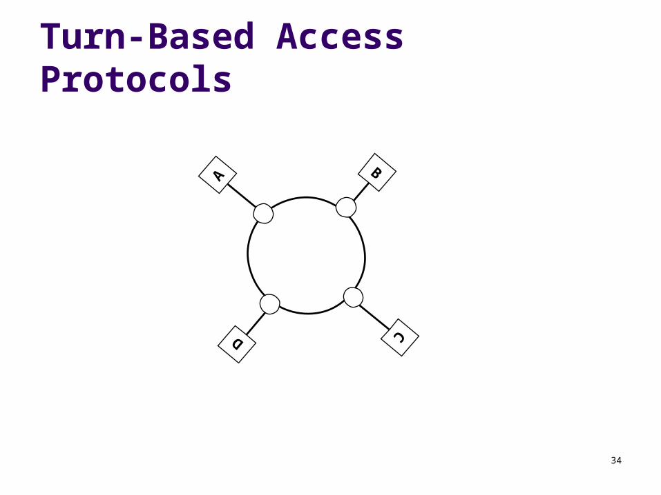
Turn-Based Access Protocols
A
D
C
B
35
IEEE 802 LANs
LAN: Local Area Network What is a local area network?
A LAN is a network that resides in a geographically restricted area
LANs usually span a building or a campus
36
Characteristics of LANs
Short propagation delays
Small number of users
Single shared medium (usually)
Inexpensive
37
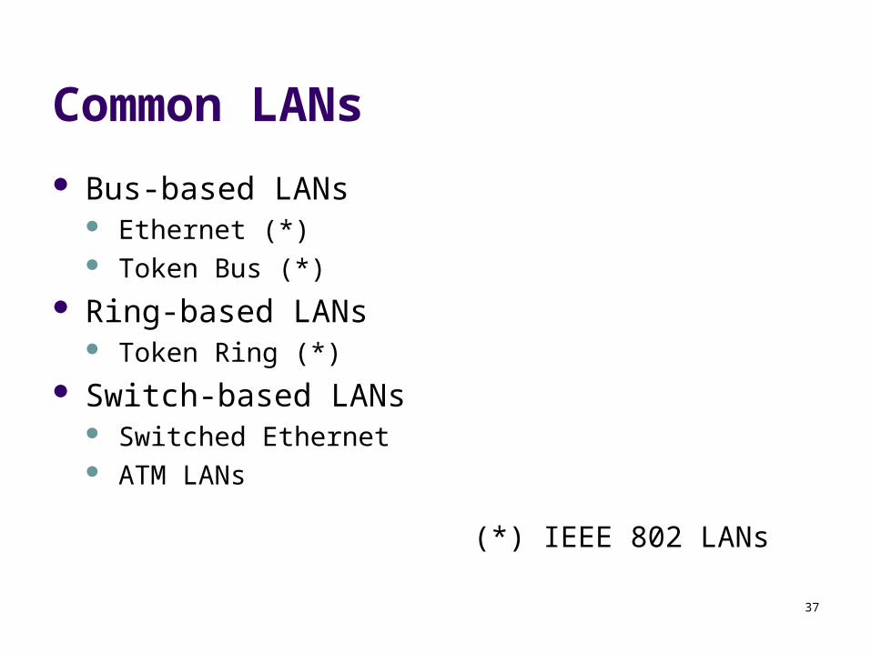
Common LANs
Bus-based LANs Ethernet (*) Token Bus (*)
Ring-based LANs Token Ring (*)
Switch-based LANs Switched Ethernet ATM LANs
(*) IEEE 802 LANs
38
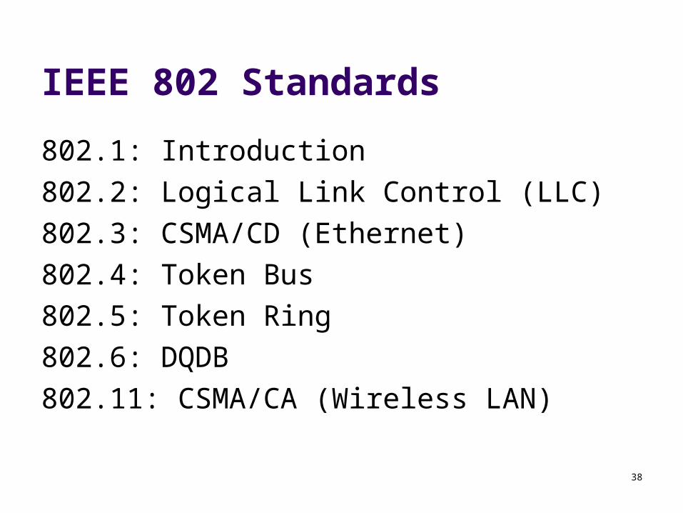
IEEE 802 Standards
802.1: Introduction
802.2: Logical Link Control (LLC)
802.3: CSMA/CD (Ethernet)
802.4: Token Bus
802.5: Token Ring
802.6: DQDB
802.11: CSMA/CA (Wireless LAN)
39
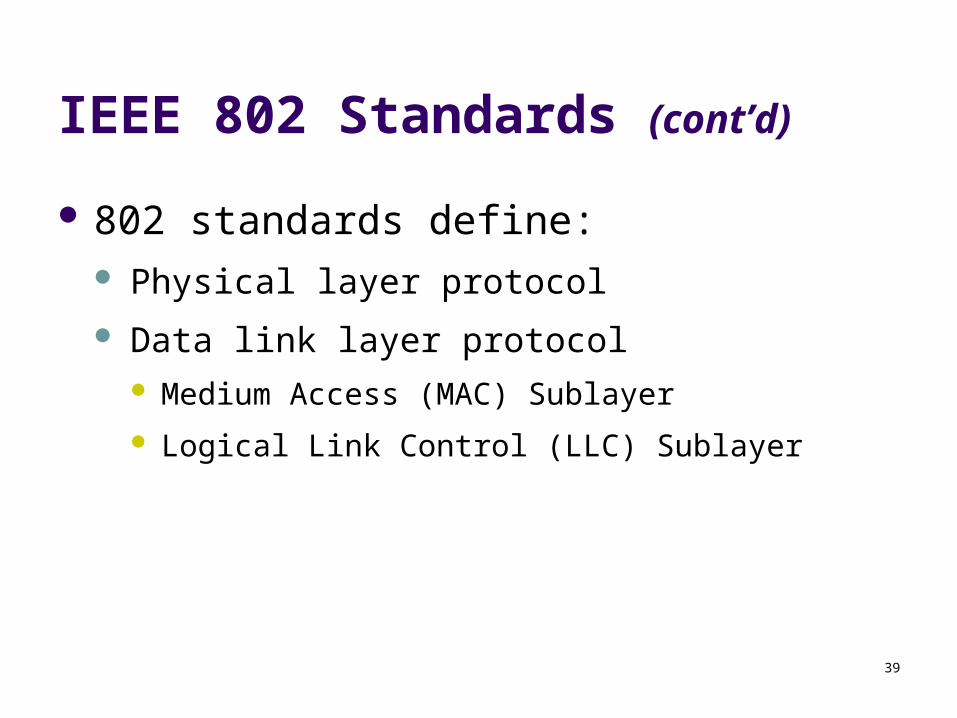
IEEE 802 Standards (cont’d)
802 standards define: Physical layer protocol
Data link layer protocol Medium Access (MAC) Sublayer
Logical Link Control (LLC) Sublayer
40
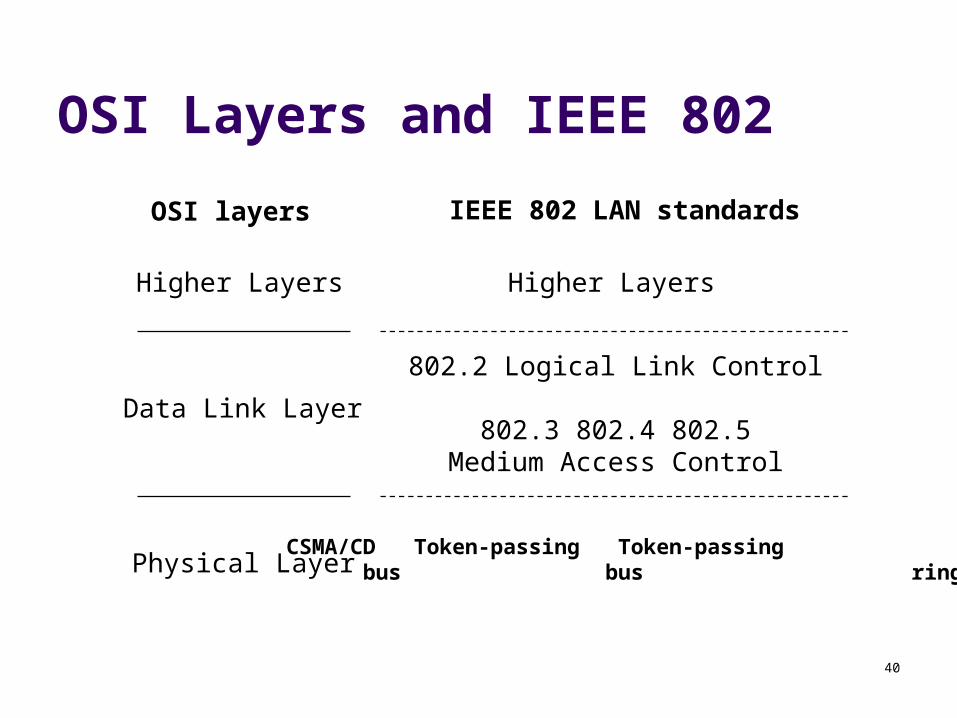
OSI Layers and IEEE 802
802.2 Logical Link Control
802.3 802.4 802.5Medium Access Control
Data Link Layer
Physical Layer
Higher Layers
OSI layers IEEE 802 LAN standards
Higher Layers
CSMA/CD Token-passing Token-passing bus bus ring
41
IEEE 802 LANs (cont’d)
Ethernet Token Ring
42
Ethernet (CSMA/CD)
IEEE 802.3 defines Ethernet Layers specified by 802.3:
Ethernet Physical Layer Ethernet Medium Access (MAC) Sublayer
43
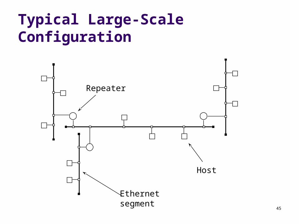
Ethernet (cont’d)
Possible Topologies:
1. Bus
2. Branching non-rooted tree for large Ethernets
44
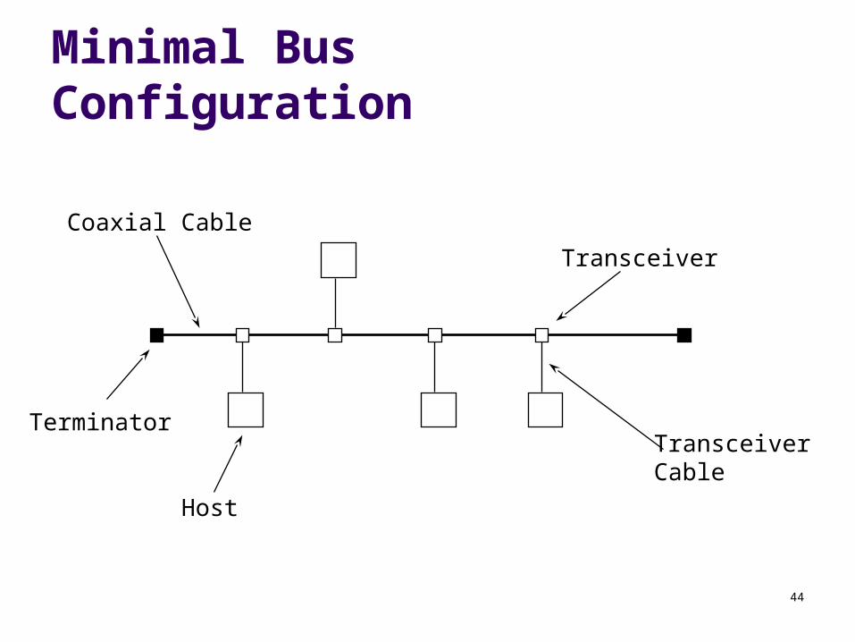
Minimal Bus Configuration
Host
Transceiver
TransceiverCable
Coaxial Cable
Terminator
45
Typical Large-Scale Configuration
Host
Repeater
Ethernetsegment
46
Ethernet Physical Layer
Transceiver Transceiver Cable
4 Twisted Pairs 15 Pin Connectors
Channel Logic Manchester Phase Encoding 64-bit preamble for synchronization
47
Ethernet Cabling Options
10Base5: Thick Coax 10Base2: Thin Coax (“cheapernet”) 10Base-T: Twisted Pair 10Base-F: Fiber optic Each cabling option carries with it a different set of
physical layer constraints (e.g., max. segment size, nodes/segment, etc.)
48
Ethernet Physical Configuration
For thick coaxial cable Segments of 500 meters maximum Maximum total cable length of 1500 meters
between any two transceivers Maximum of 2 repeaters in any path Maximum of 100 transceivers per segment Transceivers placed only at 2.5 meter marks on
cable
49
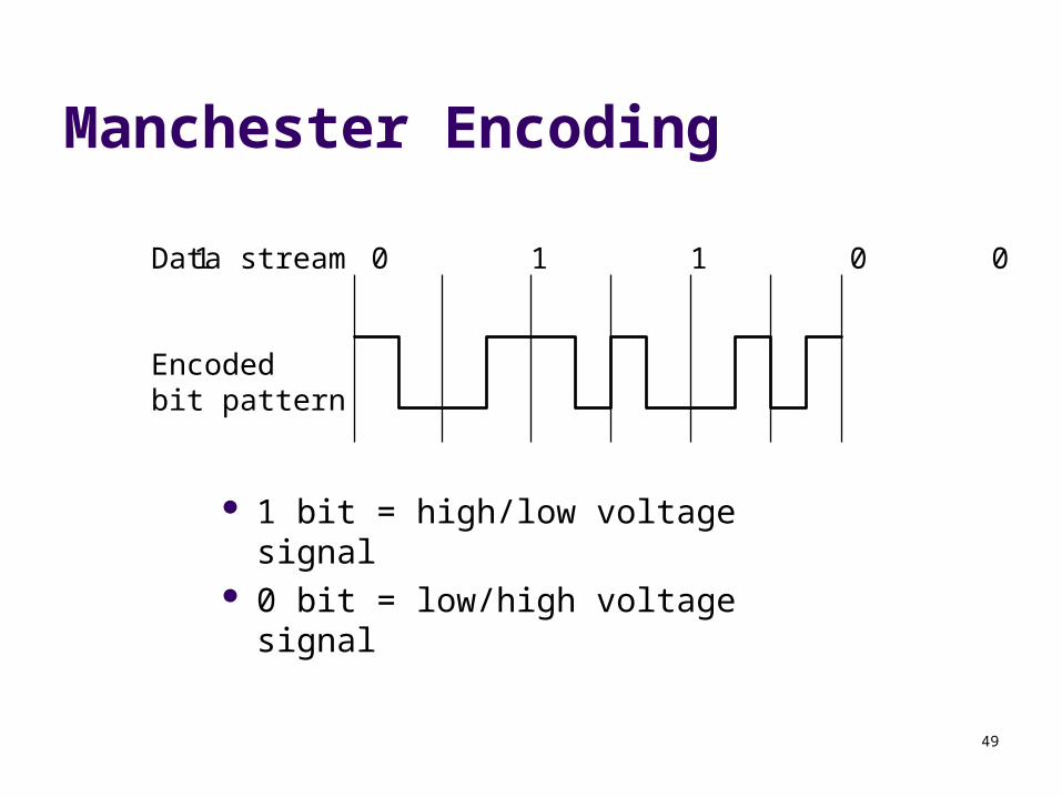
Manchester Encoding
1 bit = high/low voltage signal 0 bit = low/high voltage signal
1 0 1 1 0 0Data stream
Encodedbit pattern
50
Ethernet Synchronization
64-bit frame preamble used to synchronize reception
7 bytes of 10101010 followed by a byte containing 10101011
Manchester encoded, the preamble appears like a sine wave
51
Ethernet: MAC Layer
Data encapsulation Frame Format Addressing Error Detection
Link Management CSMA/CD Backoff Algorithm
52
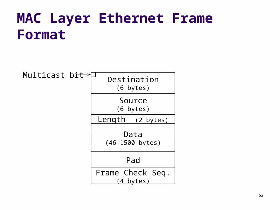
Frame Check Seq.(4 bytes)
MAC Layer Ethernet Frame Format
Destination(6 bytes)
Length (2 bytes)
Data(46-1500 bytes)
Pad
Source(6 bytes)
Multicast bit
53
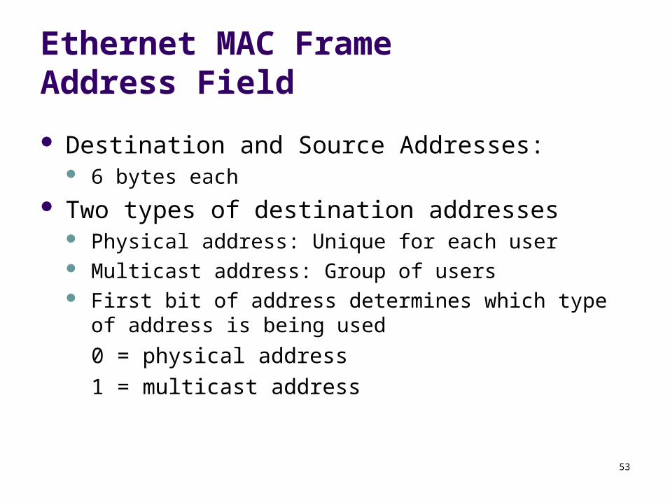
Ethernet MAC Frame Address Field
Destination and Source Addresses: 6 bytes each
Two types of destination addresses Physical address: Unique for each user Multicast address: Group of users First bit of address determines which type of address is
being used
0 = physical address
1 = multicast address
54
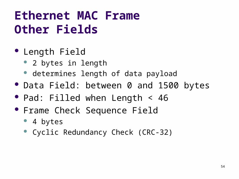
Ethernet MAC FrameOther Fields
Length Field 2 bytes in length determines length of data payload
Data Field: between 0 and 1500 bytes Pad: Filled when Length < 46 Frame Check Sequence Field
4 bytes Cyclic Redundancy Check (CRC-32)
55
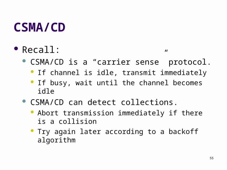
CSMA/CD
Recall: CSMA/CD is a “carrier sense” protocol.
If channel is idle, transmit immediately If busy, wait until the channel becomes idle
CSMA/CD can detect collections. Abort transmission immediately if there is a collision Try again later according to a backoff algorithm
56
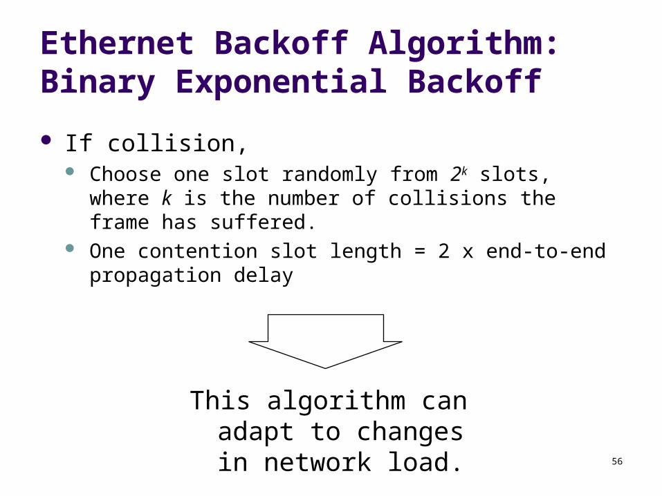
Ethernet Backoff Algorithm:Binary Exponential Backoff
If collision, Choose one slot randomly from 2k slots, where k is the
number of collisions the frame has suffered. One contention slot length = 2 x end-to-end propagation
delay
This algorithm can adapt to changes in network load.
57
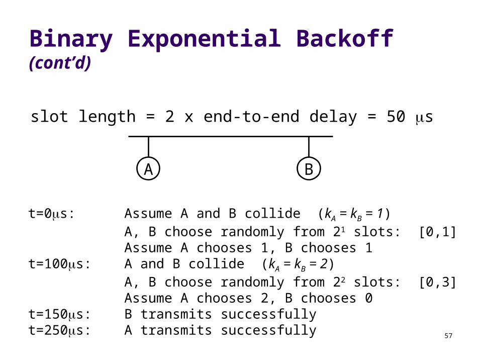
Binary Exponential Backoff (cont’d)
slot length = 2 x end-to-end delay = 50 s
A B
t=0s: Assume A and B collide (kA = kB = 1)A, B choose randomly from 21 slots: [0,1]Assume A chooses 1, B chooses 1
t=100s: A and B collide (kA = kB = 2)A, B choose randomly from 22 slots: [0,3]Assume A chooses 2, B chooses 0
t=150s: B transmits successfullyt=250s: A transmits successfully
58
Binary Exponential Backoff (cont’d)
In Ethernet, Binary exponential backoff will allow a maximum
of 15 retransmission attempts If 16 backoffs occur, the transmission of the frame
is considered a failure.
59
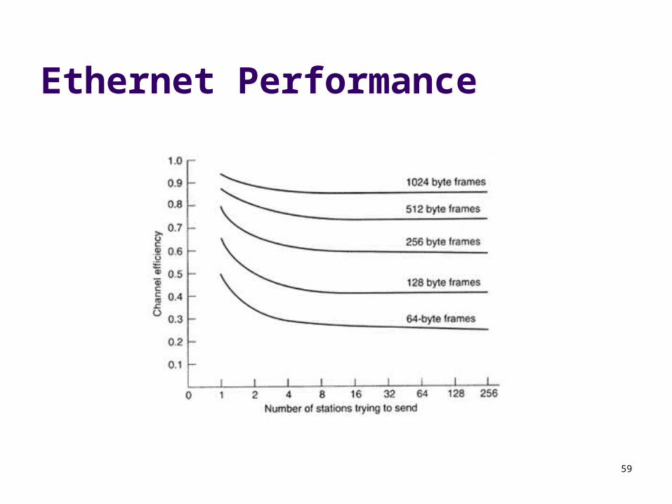
Ethernet Performance
60
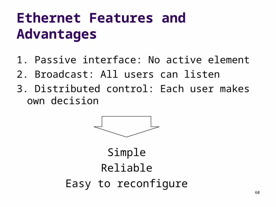
Ethernet Features and Advantages
1. Passive interface: No active element
2. Broadcast: All users can listen
3. Distributed control: Each user makes own decision
Simple
Reliable
Easy to reconfigure
61
Ethernet Disadvantages
Lack of priority levels
Cannot perform real-time communication
Security issues
62
Hubs, Switches, Routers
Hub: Behaves like Ethernet
Switch: Supports multiple collision domains A collision domain is a segment
Router: operates on level-3 packets
63
Why Ethernet Switching?
LANs may grow very large The switch has a very fast backplane It can forward frames very quickly to the
appropriate subnet Cheaper than upgrading all host interfaces to
use a faster network
64
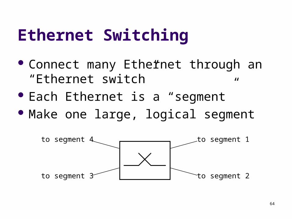
Ethernet Switching
Connect many Ethernet through an “Ethernet switch”
Each Ethernet is a “segment” Make one large, logical segment
to segment 1
to segment 2to segment 3
to segment 4
65
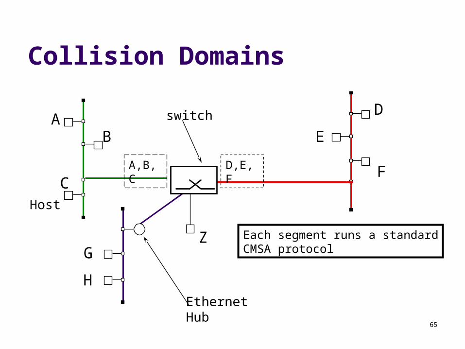
Collision Domains
Host
switch
EthernetHub
AB
C
D
E
FA,B,C D,E,F
G
H
Z Each segment runs a standardCMSA protocol
66
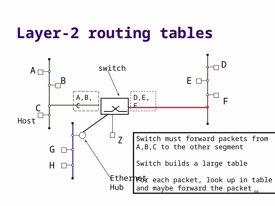
Layer-2 routing tables
Host
switch
EthernetHub
AB
C
D
E
FA,B,C D,E,F
G
H
Z Switch must forward packets fromA,B,C to the other segment
Switch builds a large table
For each packet, look up in table and maybe forward the packet
67
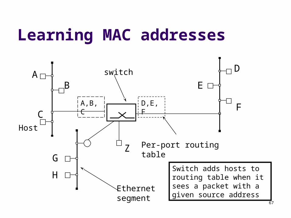
Learning MAC addresses
Host
switch
Ethernetsegment
AB
C
D
E
FA,B,C D,E,F
Per-port routing tableG
H
Z
Switch adds hosts to routing table when it sees a packet with a given source address
68
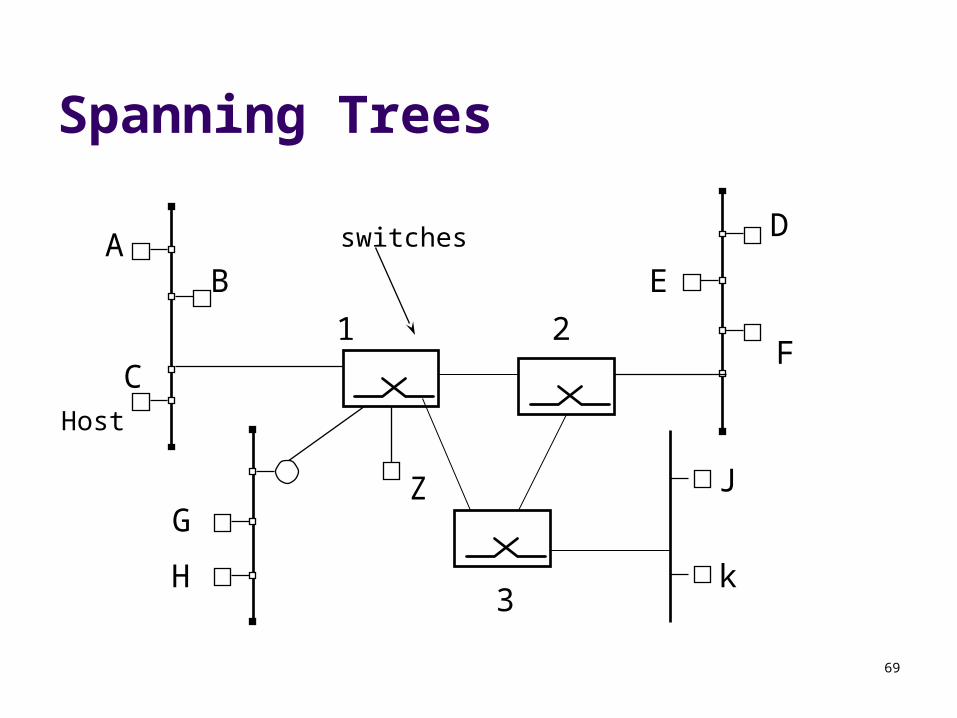
Spanning Trees
Want to allow multiple switches to connect together
What If there is a cycle in the graph of switches connected together? Can’t have packets circulate forever! Must break the cycle by restricting routes
69
Spanning Trees
Host
switchesAB
C
D
E
F
G
H
Z J
k
1 2
3
70
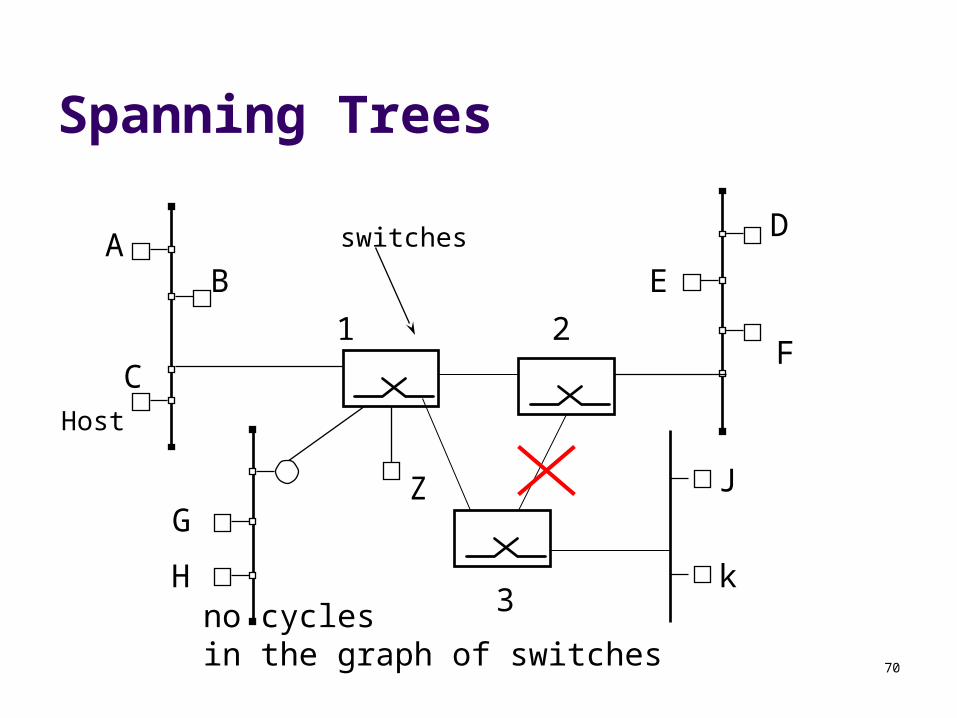
Spanning Trees
Host
switchesAB
C
D
E
F
G
H
Z J
k
1 2
3no cyclesin the graph of switches
71
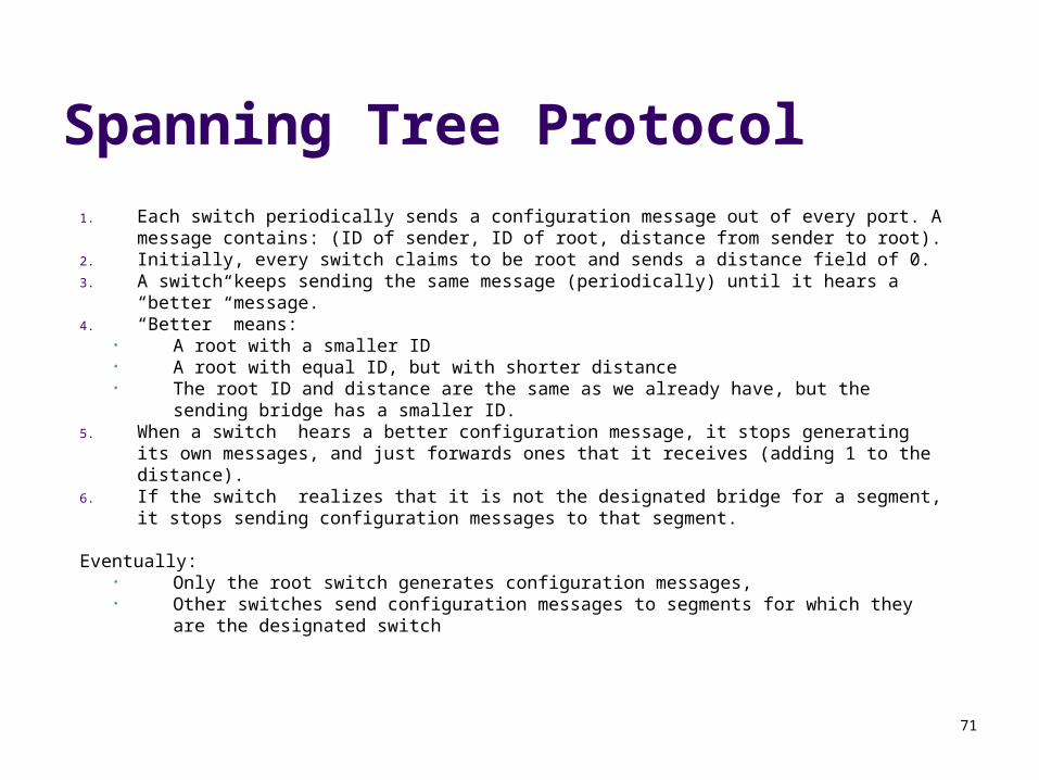
Spanning Tree Protocol
1. Each switch periodically sends a configuration message out of every port. A message contains: (ID of sender, ID of root, distance from sender to root).
2. Initially, every switch claims to be root and sends a distance field of 0.3. A switch keeps sending the same message (periodically) until it hears a “better”
message.4. “Better” means:
• A root with a smaller ID• A root with equal ID, but with shorter distance• The root ID and distance are the same as we already have, but the sending bridge
has a smaller ID.5. When a switch hears a better configuration message, it stops generating its own
messages, and just forwards ones that it receives (adding 1 to the distance).6. If the switch realizes that it is not the designated bridge for a segment, it stops sending
configuration messages to that segment.
Eventually:• Only the root switch generates configuration messages,• Other switches send configuration messages to segments for which they are the
designated switch
72
Token Ring
IEEE 802.5 Standard Layers specified by 802.5:
Token Ring Physical Layer Token Ring MAC Sublayer
73
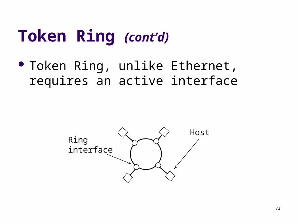
Token Ring (cont’d)
Token Ring, unlike Ethernet, requires an active interface
HostRinginterface
74
Token Ring Physical Layer
Ring Interfaces Listen and Transmit Modes
Channel Logic Differential Manchester Encoding
75
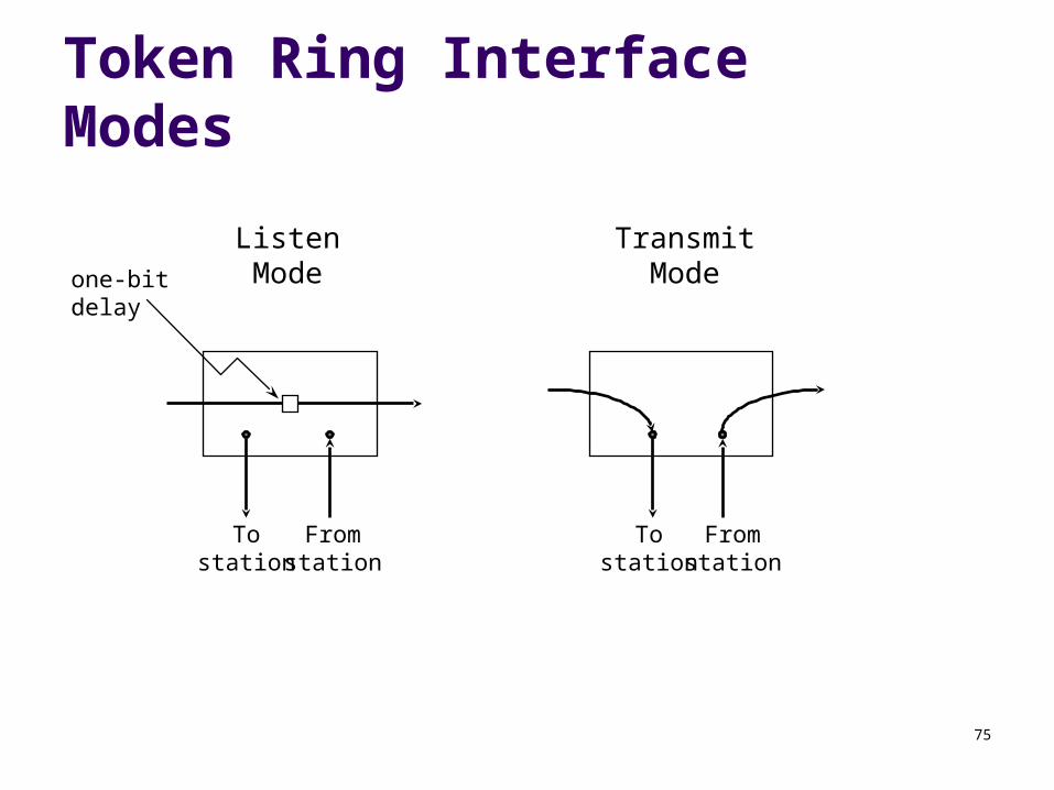
Token Ring Interface Modes
Tostation
Fromstation
Tostation
Fromstation
ListenMode
TransmitModeone-bit
delay
76
Differential Manchester Encoding
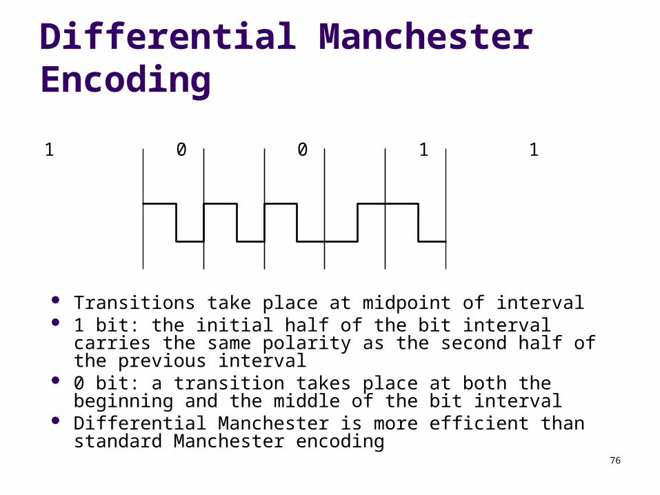
1 0 0 1 1
Transitions take place at midpoint of interval 1 bit: the initial half of the bit interval carries the same
polarity as the second half of the previous interval 0 bit: a transition takes place at both the beginning and the
middle of the bit interval Differential Manchester is more efficient than standard
Manchester encoding
77
Token Ring MAC Sublayer
Token passing protocol Frame format Token format
78
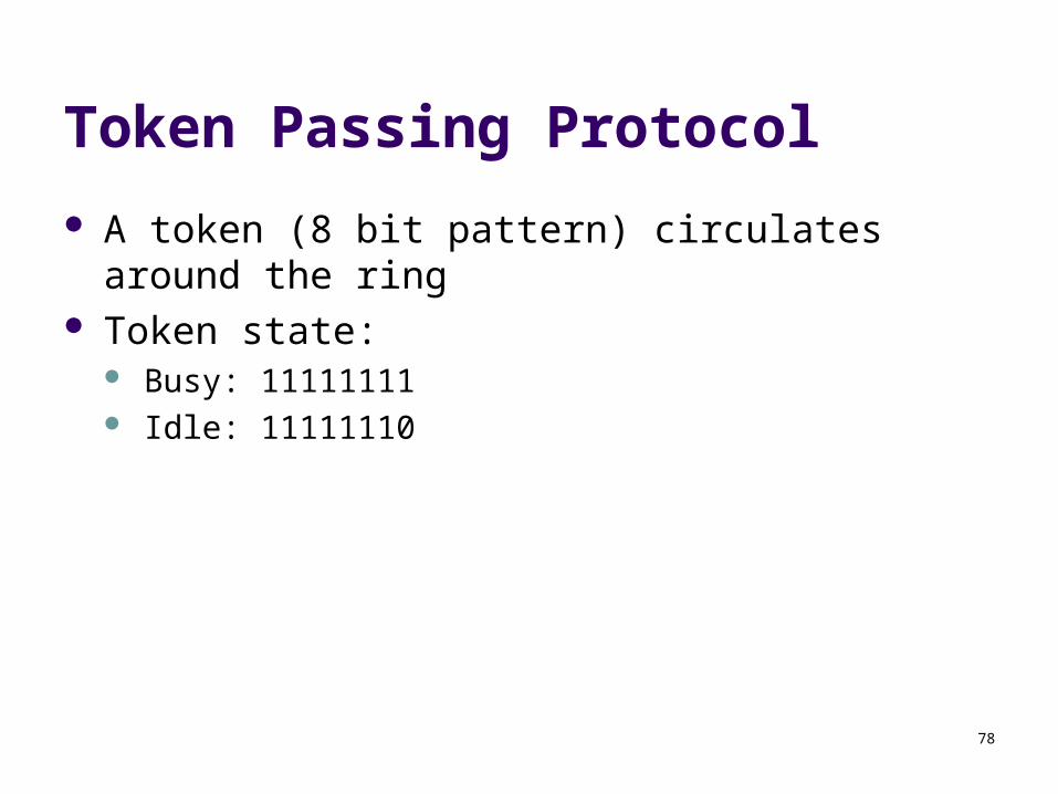
Token Passing Protocol
A token (8 bit pattern) circulates around the ring Token state:
Busy: 11111111 Idle: 11111110
79
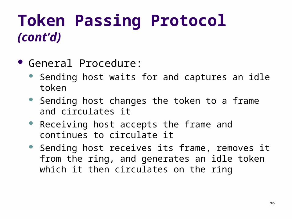
Token Passing Protocol (cont’d)
General Procedure: Sending host waits for and captures an idle token Sending host changes the token to a frame and circulates
it Receiving host accepts the frame and continues to
circulate it Sending host receives its frame, removes it from the ring,
and generates an idle token which it then circulates on the ring
80
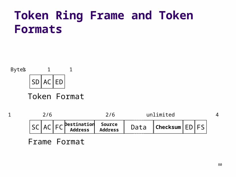
Token Ring Frame and Token Formats
SD AC ED
SC AC FC DestinationAddress
SourceAddress Data Checksum ED FS
Token Format
Frame Format
1 1 1
1 1 1 2/6 2/6 unlimited 4 1 1
Bytes
81
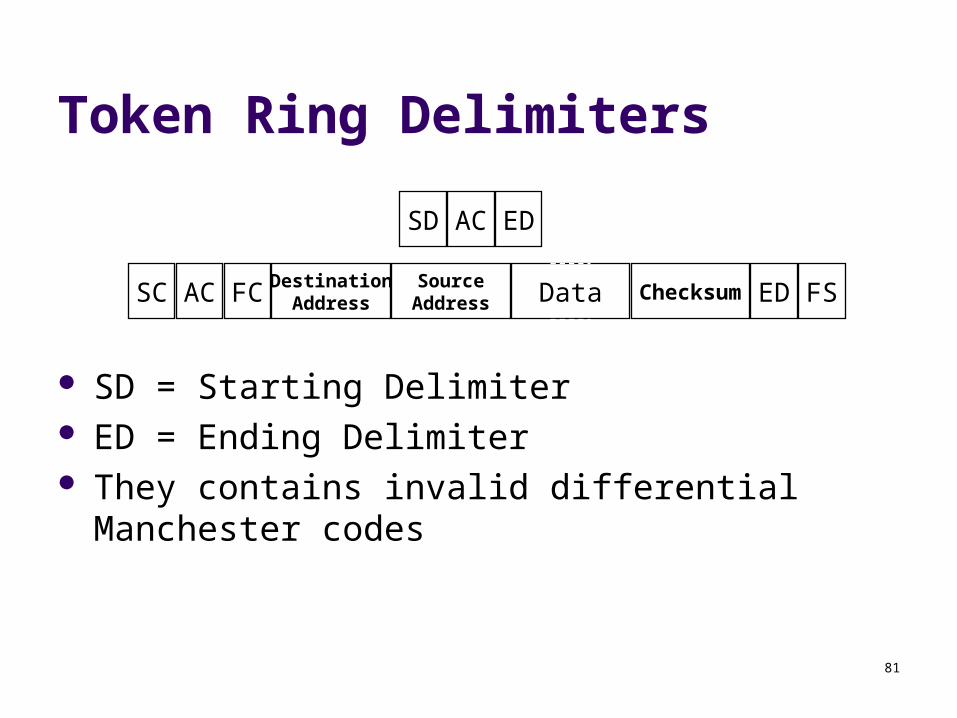
Token Ring Delimiters
SD = Starting Delimiter ED = Ending Delimiter They contains invalid differential Manchester codes
SD AC ED
SC AC FC DestinationAddress
SourceAddress Data Checksum ED FS
82
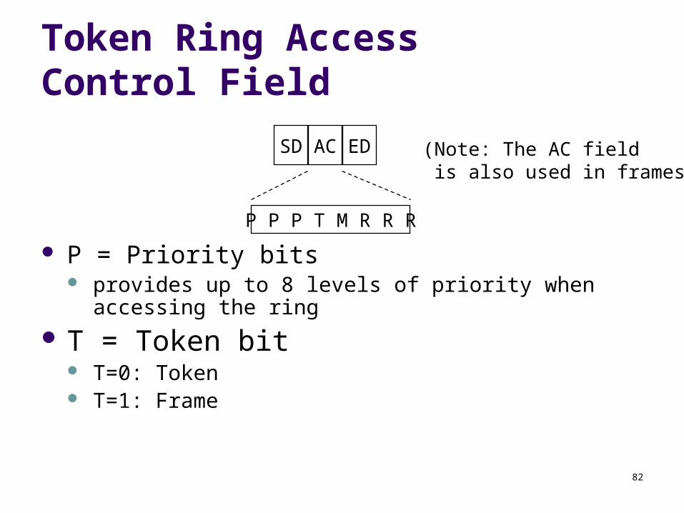
Token Ring Access Control Field
P = Priority bits provides up to 8 levels of priority when accessing the ring
T = Token bit T=0: Token T=1: Frame
SD AC ED
P P P T M R R R
(Note: The AC field is also used in frames)
83
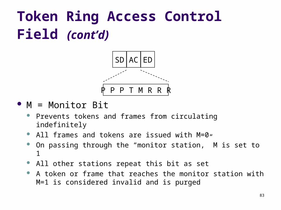
Token Ring Access Control Field (cont’d)
SD AC ED
P P P T M R R R
M = Monitor Bit Prevents tokens and frames from circulating indefinitely All frames and tokens are issued with M=0 On passing through the “monitor station,” M is set to 1 All other stations repeat this bit as set A token or frame that reaches the monitor station with M=1 is
considered invalid and is purged
84
The Token Ring Monitor Station
One station on the ring is designated as the “monitor station”
The monitor station: marks the M bit in frames and tokens removes marked frames and tokens from the ring watches for missing tokens and generates new ones after
a timeout period
85
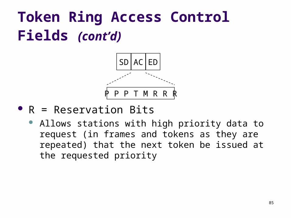
Token Ring Access Control Fields (cont’d)
SD AC ED
P P P T M R R R
R = Reservation Bits Allows stations with high priority data to request (in frames
and tokens as they are repeated) that the next token be issued at the requested priority
86
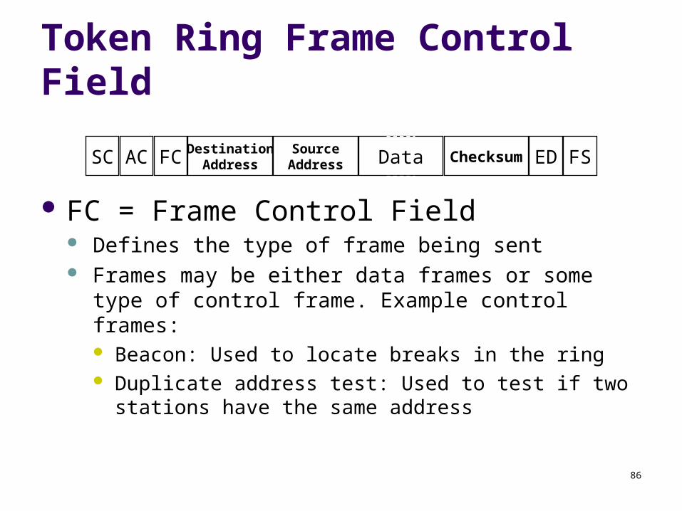
Token Ring Frame Control Field
FC = Frame Control Field Defines the type of frame being sent Frames may be either data frames or some type of control
frame. Example control frames: Beacon: Used to locate breaks in the ring Duplicate address test: Used to test if two stations have the
same address
SC AC FC DestinationAddress
SourceAddress Data Checksum ED FS
87
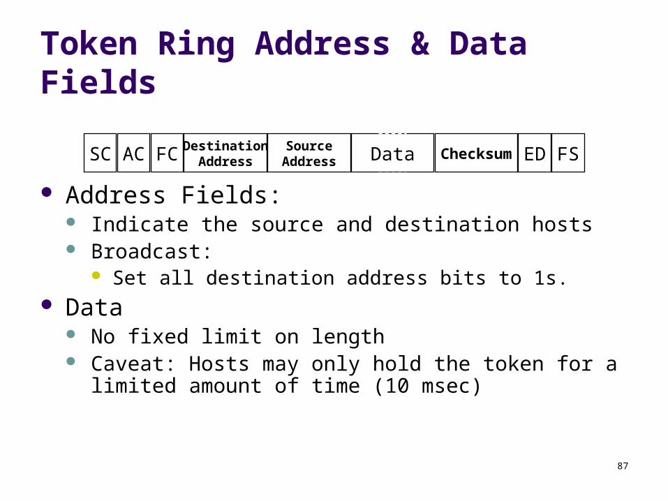
Token Ring Address & Data Fields
Address Fields: Indicate the source and destination hosts Broadcast:
Set all destination address bits to 1s. Data
No fixed limit on length Caveat: Hosts may only hold the token for a limited amount
of time (10 msec)
SC AC FC DestinationAddress
SourceAddress Data Checksum ED FS
88
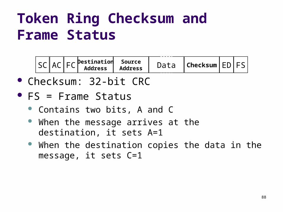
Token Ring Checksum and Frame Status
Checksum: 32-bit CRC FS = Frame Status
Contains two bits, A and C When the message arrives at the destination, it sets A=1 When the destination copies the data in the message, it
sets C=1
SC AC FC DestinationAddress
SourceAddress Data Checksum ED FS
89
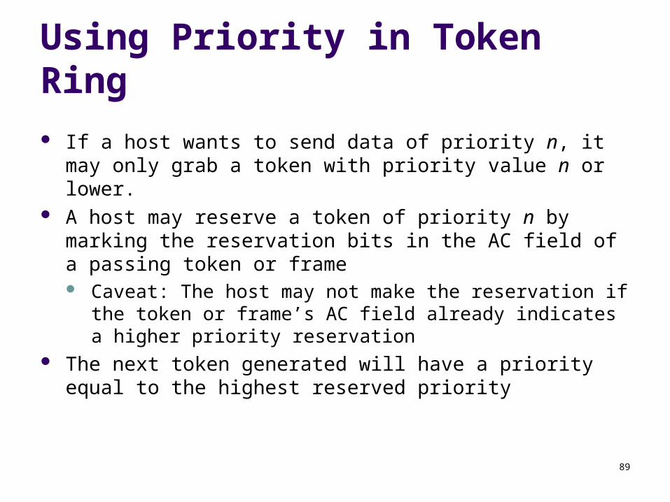
Using Priority in Token Ring
If a host wants to send data of priority n, it may only grab a token with priority value n or lower.
A host may reserve a token of priority n by marking the reservation bits in the AC field of a passing token or frame Caveat: The host may not make the reservation if the token or
frame’s AC field already indicates a higher priority reservation The next token generated will have a priority equal to the highest
reserved priority
90
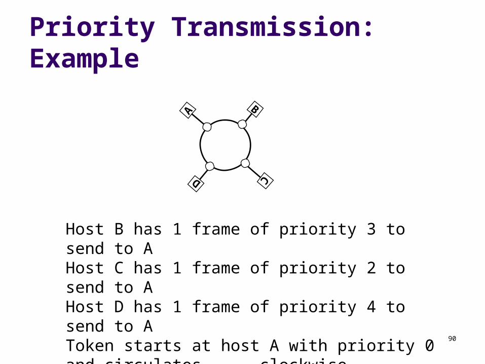
Priority Transmission: Example
AD
C
B
Host B has 1 frame of priority 3 to send to AHost C has 1 frame of priority 2 to send to AHost D has 1 frame of priority 4 to send to AToken starts at host A with priority 0 and circulates
clockwiseHost C is the monitor station
91
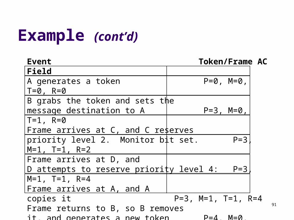
Example (cont’d)
Event Token/Frame AC FieldA generates a token P=0, M=0, T=0, R=0B grabs the token and sets themessage destination to A P=3, M=0, T=1, R=0Frame arrives at C, and C reservespriority level 2. Monitor bit set. P=3, M=1, T=1, R=2Frame arrives at D, andD attempts to reserve priority level 4: P=3, M=1, T=1, R=4Frame arrives at A, and Acopies it P=3, M=1, T=1, R=4Frame returns to B, so B removesit, and generates a new token P=4, M=0, T=0, R=0Token arrives at C, but its priority istoo high. C reserves priority 2. M bit. P=4, M=1, T=0, R=2
92
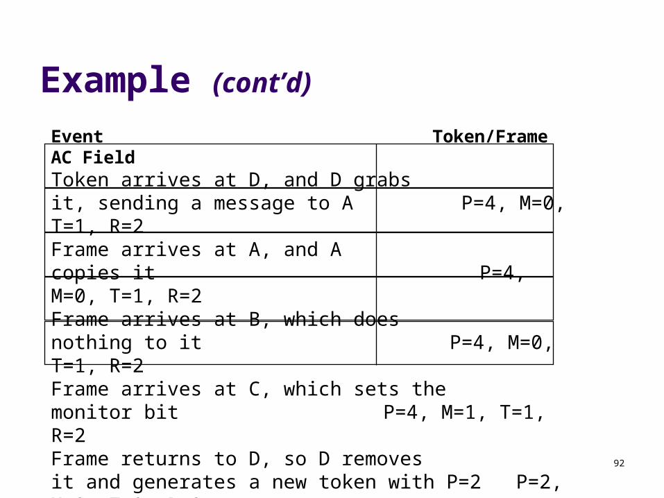
Example (cont’d)Event Token/Frame AC FieldToken arrives at D, and D grabsit, sending a message to A P=4, M=0, T=1, R=2Frame arrives at A, and A copies it P=4, M=0, T=1, R=2Frame arrives at B, which doesnothing to it P=4, M=0, T=1, R=2Frame arrives at C, which sets themonitor bit P=4, M=1, T=1, R=2Frame returns to D, so D removesit and generates a new token with P=2 P=2, M=0, T=0, R=0
etc… Attempt to complete this scenario on your own.