LINK-11 Communications
61
G0 NAVAL POSTGRADUATE SCHOOL Monterey, California AD-A25 2 766 DTIC .... ELECTE JUL 15 1992 U THESIS A LINK-l1 COMMUNICATIONS by Thor A. Simensen March 1992 Principal Advisor: Thomas A. Schwendtner Approved for public release; distribution is unlimited 92-18201 9 2 " 0 ,IIllldJIIlIrllIIl I
Transcript of LINK-11 Communications

G0NAVAL POSTGRADUATE SCHOOL
Monterey, CaliforniaAD-A252 766
DTIC.... ELECTE
JUL 15 1992 UTHESIS A
LINK-l1 COMMUNICATIONS
by
Thor A. Simensen
March 1992
Principal Advisor: Thomas A. Schwendtner
Approved for public release; distribution is unlimited
92-182019 2 " 0 ,IIllldJIIlIrllIIl I

UNCLASSIFIEDSECURITY CLAS' IFICATION OF THIS PAGE
SForm Approved
REPORT DOCUMENTATION PAGE OMB No. 0704.0188
la REPORT SECURITY CLASSIFICATION lb RESTRICTIVE MARKINGS
UNCLASSIFIED2a SECURITY CLASSIFICATION AUTHORITY 3 DISTRIBUTION) AVAILABILITY OF REPORT
2b DECLASSIFICATON/D'OWNGRADING SCHEDULE Approved for public release;distribution is unlimited
4 PERFORMING ORGANIZATION REPORT NUMBER(S) 5 MONITORING ORGANIZATION REPORT NUMBER(S)
6a NAME OF PERFORMING ORGANIZATION 6b OFFICE SYMBOL 7a NAME OF MONITORING ORGANIZATION
(If applicable)
Naval Postgraduate School AS Naval Postgraduate School6c, ADDRESS (ity, State, and ZIP Code) 7b. ADDRESS (City, State, and ZIP Code)
Monterey, CA 93943-5000 Monterey, CA 93943-5000
8a NAME OF FUNDING/SPONSORING 8b OFFICE SYMBOL 9 PROCUREMENT INSTRUMENT IDENTIFICATION NUMBERORGANIZATION (If applicable)
Bc. ADDRESS (City, State, and ZIP Code) 10 SOURCE OF FUNDING NUMBERSPROGRAM PROJECT TASK WORK UNITELEM[zNT NO NO NO ACCESSION NO.
11 TITLE (Include Security Classification)
LINK-1i COMMUNICATIONS
12 PERSONAL AUTHOR(S)SIMENSEN l Thor A."I'3a YPE OF REPORT 13b TIME COVERED 14 DATE OF: REPORT (Year, Month Day) ' 15 PAGE COUNTMaster's Thesis FROM TO 1.992 March 6116 SUPPLEMENTARY NOTATION The views expressed in this thesis are those of theauthor and do not reflect the official policy or position of the Depart-ment of Defense or the US Government.17 COSATI CODES 18 SUBJECT TERMS (Continue on reverse if necessary and identify by block number)
FIELD GROUP SUB.GROUP Link-li; NTDS
19 ABSTRACT (Continue on reverse if necessary and identify by block number)This thesis provides the reader with anoverview of the Link-Il system and what telecommunication assets are needed to operatethe system. Fundamental aspects of High Frequency (HF), Ultra High Frequency (UHF), andcommunication configurations are reviewed. An examination of the Link-li equipment op-erations is presented. This includes a description of the Tactical Data Set (TDS) com-puter and encryption device. The thesis also contains an in-depth review of the DataTerminal Set (DTS). The specific operations of the DTS that are studied are Error Detec-tion and Correction (EDAC), audio signal generation, link control, NTDS ct'.iuter inter-face, and digital/analog conversion.
Distinctive Link-li communication features are discussed. These features cousist ofPhase Shift Keying (PSK), signal generation, signal structure, and binary coding. Theprotocol, consisting o'' the frame structure, control codes, and net operation, which op-erates the net automatically is introduced. A review of radio equipment and itsmanagement concludes the thesis.20 DISTRIBUTION/ AVAILABILITY OF ABSTRACT 21 ABSTRACT SECURITY CLASSIFICAT71ON '
[ XUNCLASSIFIEWUNLIMITED 0] SAME AS RPT []DTIC USERS UNCLASSIFIED22o NAME OF RESPONSIBLE INDIVIDUAL 22b TELEPHONE (include Area Code) 22c OFFICE SYMBOL
SCHWENDTNER, Thomas A. 1408-646-3117 1 ECISnDD Form 1473, JUN 86 Previuus editions are obsolete. SECURITY CLASSIFICATION OF THIS PACE
S/N 0102-LF-014-6603 UNCLASSIFIEDi
I III IIIII III I II I I I I I I m ,, -- j

Approved for public release; distribution is unlimited.
Link-il Communications
by
Thor A. SimensenLieutenant, United States Navy
B.S., Trevecca Nazarene College, 1984
Submitted in partial fulfillment
of the requirements for the degree of
MASTER OF SCIENCE IN TELECOMMUNICATIONS SYSTEMS MANAGEMENT
Irom the
NAVAL POSTGRADUATE SCHOOLMarch 1992
Author: >~Tho /-. ,%mcinsen
Approved by: #-( ,/
Scwnner icpa dio

ABSTRACT
This thesis provides the reader with an overview of the Link-11 system and what
telecommunication assets are needed to operate the system. Fundamental aspects of High Frequency
(HF), Ultra High Frequency (UHF), and communication configurations are reviewed. An examination
of the Link-l1 equipment operations is presented. This includes a description of the Tactical Data Set
(TDS) computer and encryption device. The thesis also contains an in-depth review of the Data
Terminal Set (DTS). The specific operations of the DTS that are studied are Error Detection and
Correction (EDAC), audio signal generation, link protocol control, NTDS computer interface, and
digital/analog conversion.
Distinctive Link-li communication features are discussed. These features consist of Phase Shift
Keying (PSK), signal generation, signal structure, and binary encoding. The protocol, consisting of the
frame structure, control codes, and net operation, which operates the net automatically is introduced.
A review of radio equipment and its management concludes the thesis.
iii

TABLE OF CONTENTS
I. INTRODUCTION . . . . . . . . . . . . . . . . . . . 1
A. PURPOSE . . . . . . . . . . . . . . . . . . . . 1
B. ORGANIZATION AND SCOPE . . . . . . . . . . . . 2
II. COMMUNICATION FUNDAMENTALS. . . . . . . . . . . 4
A. TERMINALS . . . . . . . . . . . . . . . . . . . 4
B. SWITCHING . . . . . . . . . . . . . . . . . . . 4
C. TRANSMISSION . . . . . . . . . . . . . . . . . 6
D. RADIO FREQUENCY (RF) . . . . . . . . . . . . . 6
1. High Frequency. . . . . . . . . . . . . . . 7
2. Ultra High Frequency . . . . . . . . . . . . 7
III. GENERAL DESCRIPTION . . . . . . . . . . . . . . . 8
A. DATA LINK DESCRIPTION. . . . . . . . . . .. . 8
B. DATA LINK TERMS . . . . . . . . . . . . . . . . 10
1. Link-11 Unit . . . . . . . . . . . . . . . . 11
2. Tactical Data System (TDS) . . . . . . . . . 11
3. Participating Unit (PU) . . . . . . . . . . 11
4. Forwarding Participating Unit (FPU) . . . . 11
5. Gridlock . . . . . . . . . . . . . . . . . . 11
6. Net Coordinator . . . . . . . . . . . . . . 12
7. Unit System Coordinator . . . . . . . . . . 12
iv
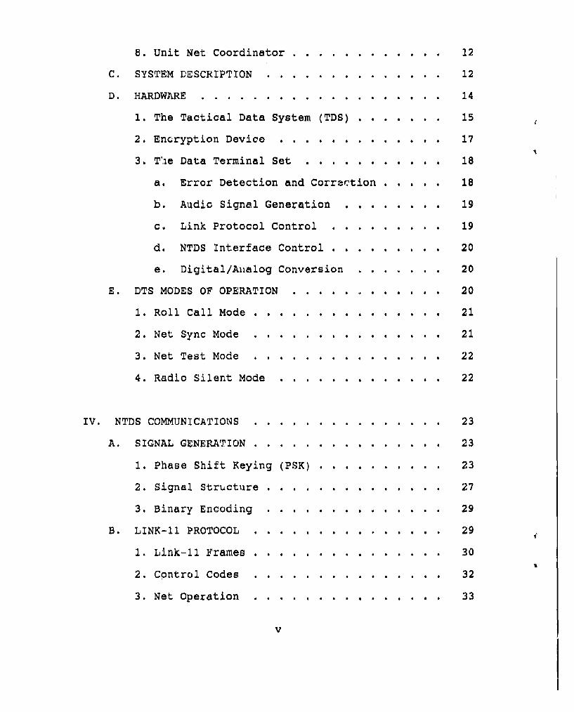
8. Unit Net Coordinator .............. . 12
C. SYSTEM DESCRIPTION .... .............. .. 12
D. HARDWARE ....... ................... .. 14
1. The Tactical Data System (TDS) . .. 15
2. Encryption Device . . . . . . . ...... 17
3. Tie Data Terminal Set . . . . . ...... 18
a. Error Detection and Correction ..... 18
b. Audio Signal Generation . . ...... 19
c. Link Protocol Control . . ....... 19
d. NTDS Interface Control . . . ...... 20
e. Digital/Aialog Conversion . ....... . 20
E. DTS MODES OF OPERATION . . . . . . . . . . .. 20
1. Roll Call Mode . . . . . . . . . . . . . . . 21
2. Net Sync Mode . . . . . . . . . . . . . . 21
3. Net Test Mode . . . . . . . . . . . . . . . 22
4. Radio Silent Mode . . . . . . . . . . . . . 22
IV. NTDS COMMUNICATIONS . . . . ... .............. 23
A. SIGNAL GENERATION . ..... ........... . .. 23
1. Phase Shift Keying (PSK) ..... .. . 23
2. Signal Structure .. . .... .. . 27
3. Binary Encoding .. .. ........ 29
B. LINK-i PROTOCOL ... ...... . . 29
1. Link-ll Frames ....................... 30
2. Control Codes .............. ... 32
3. Net Operation ... ...... .... 33
v

4. Net Cycle Time (NCT) .. ....... . . 35
C. RADIO EQUIPMENT ....... . ............ . . 36
1. HF Communications . . . . . . . . 36
2. UHF Communications . . . . . . . . 37
V. SYSTEM MANAGEMENT ................. 40
A. FREQUENCY MANAGEMENT . . . . . . . . . . . . . 41
B. SIGNAL EXPLOITATION/JAMMING . . . . . . . . . . 44
C. RECEPTION QUALITY . . . . . . . . . . . . . . . 45
VI. CONCLUSION . . . . . . . . . . . . . . . . . . . . 49
At OTCIXS # . . . . . . . . . . . . . . . . 49
B. DANA . . . . . . . . . . . . . . . . . . . . . 50
C. SUMMARY .S . * . . . . . . . . . . . .. .*. . 52
LIST OF REFERENCES . . . . . . . . . . . . . . . . . . 53
INITIAL DISTRIBUTION LIST . . . . . . . . . . . . . .. 54
vi

I. INTRODUCTION
As the world has grown both technologically and socially,
the importance of protected sea lanes has steadily increased.
Since man first set sail, the seas have proven to be the
primary source of transporting supplies. The United States is
separated from the majority of the developed nations by vast
oceans, so secure sea lanes have been of utmost importance to
the nation's survival.
The projection of sea power by battle group commanders has
been the essence of the United States Navy. Initially, naval
forces were limited to attacking and defending forces that
were within the visual horizon. But the introduction of over-
the-horizon weapons and surveillance techniques has brought
sweeping changes in naval operations.
Today, commanders need to be able to detect hostile
activities as far from their own unit as possible. Link-li
technology enables units of a battle group to exchange real-.
time tactical information that has been detected by their own
sensors. By sharing this tactical information, commanders are
essentially extending their own detection capabilities.
A. PURPOSE
The conuDunications over the Link-il circuit plays a vital
and integral part of battle group operations. This study is
1

intended to provide communicators with a overview of the Link-
11 system. A review of the telecommunication assets needed to
operate the system is presented, and some perspectives of how
communicators can manage the Link-li network is provided.
This study's purpose is not to determine if new
telecommunications technology is necessary, nor will it
attempt to develop new technology. It will, however, simply
review the present assets available to achieve efficient Link-
11 communications in support of the battle group.
B. ORGANIZATION AND SCOPE
The Link-li system is an intricate and complicated
computer-to-computer communications exchange network. The
best way for communicators to manage a system is to understand
all the aspects of that system. To provide this managerial
perspective of Link-ll, the entire system is presented in the
following chapters.
Chapter II covers the basic fundamentals of communications
to prepare the reader for an in-depth study of Link-ll. It is
comprised of a review of communication terminals, switching
equipment, transmission media, and radio frequencies.
Chapter III is a general description of Link-ll. This
chapter presents a description of the different Tactical
Digital Information Link (TADIL) networks and some data link
terms. It develops an understanding of the system operation
and the equipment used to exchange the digital information.
2
Chapter IV is a detailed presentation of the Link-li
signal generation that includes phase shift keying, signal
structure, and binary encoding. This chapter also discusses
the particulars of the Link-li network protocol.
Chapter V provides a discussion of some managerial aspects
of the system; chapter VI touches on possible net alternatives
and summarizes the thesis.
3
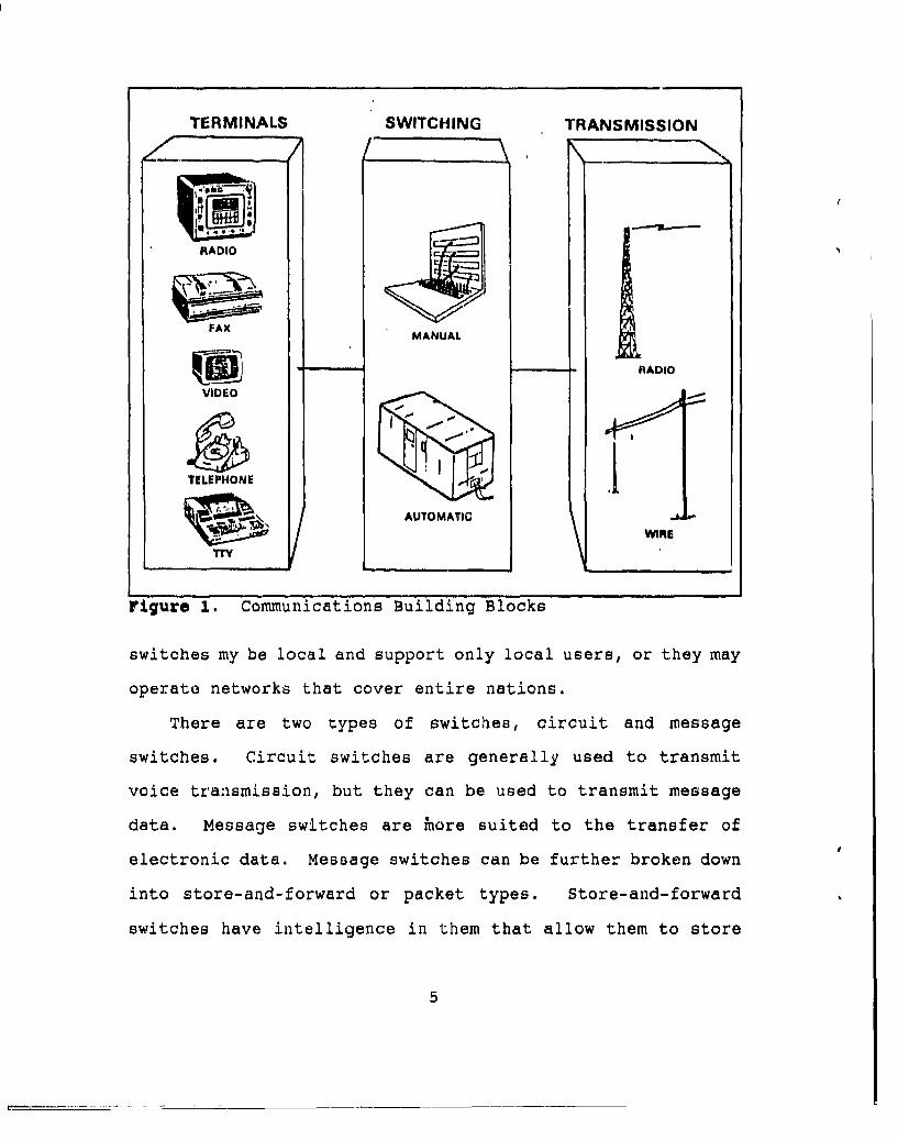
II. COMMUNICATION FUNDAMENTALS
A telecommunicqtion circuit can contain a seemingly
limitless amount of equipment to enable two or more stations
to transfer information between them. "Three essential
elements comprise any communications system: terminals,
switches, and transmission." [Ref. l:p. 2-1] These are the
basic elements needed ;o construct a circuit as illustrated in
Figure 1. Many more devices are typically added to thb
circuit to produce the type of communications desired.
A. TERMINALS
"Of all the communications equipment, terminals are
probably the most familiar to the user." [Ref. i:p. 2-1]
Terminals can consist of any number of items depending on the
type of information to be transmitted and the type of
transmission media used. A telephone is a terminal that is
common to most people. Other types of terminals include:
radio, video, facsimile, and teleprinters.
B. SWITCHING
"Switching is the means by which user traffic is routed
through a communications system." [Ref. 1:p. 2-2) These
switches may be manually operated, like the old telephone
operator switchboard, or they may be automatic. These
4
TERMINALS SWITCHING TRANSMISSION
RIO
FAX MANUAL
kRADIO
VIDEO
TELEPHONE
AUTOMATIC
WIRETTY
Figure 1. Communications Building Blocks
switches my be local and support only local users, or they may
operate networks that cover entire nations.
There are two types of switches, circuit and message
switches. Circuit switches are generally used to transmit
voice transmission, but they can be used to transmit message
data. Message switches are inore suited to the transfer of
electronic data. Message switches can be further broken down
into store-and-forward or packet types. Store-and-forward
switches have intelligence in them that allow them to store
5

parts of a message in memory and then forward the message when
the entire message has been received. Packet switches are
more adapted to handling data, since the information to be
transferred may be broken down into small packets that may
travel several different paths to arrive at the destination.
[Ref. l:p. 2-2]
C. TRANSMISSION
"Traffic exchanged between users travels between points
over radio waves, wire or cable landlines or a combination of
the two." [Ref. l:p. 2-3] These transmissions are directed by
switches which operate as an interface between terminals and
the transmission media. Transmission media consist of twisted
pair wize, coaxial cable, fiber optics, and radio waves. The
transmission of Link-il from user to user is generally
accomplished with radio waves, while on-board transmission is
accomplished through "patch panels" with twisted pair wires.
D. RADIO FREQUENCY (RF)
"The usable radio frequency spectrum extends from 30 Hertz
(Hz) to 300 Giga (billion) Hertz (GHz)." [Ref. l:p. 2-15]
Being a part of the electromagnetic spectrum, radio waves
trmvel at 186,000 miles per second (the speed of light).
Radio frequencies cover just a small portion of the
electromagnetic spectrum, and Link-li is used only in the High
Frequency (HF) and Ultra High Frequency (UHF) ranges.
6

1. High Frequency
The HF portion of the frequency spectrum is from 2 to
30 MegaHertz (MHz). HF has traditionally been used for long
haul communications for surface ships. The ground wave can
deliver ranges of up to 300 miles. HF also has a sky wave
component associated with it that allows communications of up
to one thousand miles, and sometimes several thousand miles,
depending on the atmospheric conditions.
2. Ultra High Frequency
The Navy's UHF equipment operate in the 225-400 MHz
range. UHF is typically a line-of-sight (LOS) frequency band
and is used only for short range communications. Depending on
the height of the transmitting and receiving anteiinas,
propagation ranges of 20-30 miles may be expected for ship-to-
ship transmissions. For surface-to-aircraft communications,
ranges vary depending on the altitude of the aircraft.
7

III. GENERAL DESCRIPTION
The introduction of over-the-horizon weapons triggered a
new era of battle management for the force commander. The
Department of Defense has expended an extensive portion of the
nation's research and development funds to exploit this
capability and to produce an adequate defense against it. The
development of several Tactical Digital Information Link
(TADIL) has given force commanders an additional and essential
capability to effectively fight in an over-the-horizon
environment.
A TADIL net enables units to exchange tactical information
that has been acquired by their sensors. By obtaining the
tactical situation of a unit outside the range of his/her own
unit's sensors, the commander has effectively extended the
detection capabilities of his/her unit.
A. DATA LINK DESCRIPTION
Units exchange tactical data information on a computer-to-
computer communications link known as TADIL. Like any other
telecommunications network, messages transferred over the
tactical data links must convey the same meaning to both the
transmitting and receiving stations. To accomplish this,
message standards and protocols have been established for
8

intraservice use by each of the four branches of the military,
for interservice use, and for use between U.S. and military
allies. JCS exercises control over U.S. standards, while the
CNO maintains standardization of data links for the Navy.
[Ref. 2:p. I-1)
Link-i is a NATO digital data link between land-based
units. It is a two-way, full-duplex, secure, point-to-point
link. Link-4A is the NATO designation of TATL C. It is a
one- or two-way non-secure UHF data link that controls
interceptor aircraft through surface-to-air, air-to-air, and
air-to-surface computer interface. Link-i and Link-4A have
unique message standards and protocols and do not communicate
between each other or directly interface with Link-lI/TADIL A.
Link-14 is the NATO designation of a one-way teletype
broadcast that is designed to provide information obtained in
the Link-li environment to non-NTDS ships. (Ref. 2:p. II-i]
Link-li is the NATO designation of TADIL A. The Navyhas adopted the term Link-ul in order to maintaincommonality within the NATO arena. Link-li is atactical data information link employing nettedcommunication techniques and standard message formatfor the exchange of digital information. Link-il isa half-duplex netted, normally secure, digital datalink that normally operates in a roll call mode undercontrol of a Net Control Station (NCS). Link-liprovides for the mutual exchange of information amongnet participants via HF or UHF radio. Tactical dataprocessing equipments, located at each station, arelinked together via a common transmission medium intoa netted configuration. (Ref. 2:p. II-1]
TADIL B is a full-duplex, two-way, point-to-point digital
data link. It provides a telecommunications link for the
9
transfer of data between units of the Army, Air Force, Marine
Corps and Special Information Systems (SIS). Although the
message standards are the same as Link-il, the equipment,
protocols and data rate are different; therefore, TADIL B
cannot be directly interfaced with Link-l1. (Ref. 2:p. 11-2]
Link-16 is the NATO designator for the developmental link
known as TADIL J. Link-16 merges elements of Link-il and
Link-4A into one common system that will expand the force
commander's capabilities. Link-16 is being designed to enable
it to operate with existing Link-il hardware or the Joint
Tactical Information Distribution System (JTIDS) terminal.
TADIL J refers solely to the message standard and protocol,
whereas JTIDS refers to the multipurpose communications
equipment that may be employed to operate Link-16. (Ref. 2 :p.
11-2]
The Navy Tactical Data System (NTDS) makes use of the
TADIL system to support the battle group commander at sea.
NTDS is presently supported by several TADIL components. NTDS
is composed of the Link-4A, Link-li, and Link-14 components of
TADIL.
B. DATA LINK TERMS
The following terms and definitions are provided from the
Link-i1 Operating Procedures (OPNAVINST C3120.39B) for the
reader as a basis in understanding the NTDS dialect.
10

1. Link-l1 Unit
A Link-l1 unit is a platform capable of exchanging
Link-li information. These units include: ships, submarines,
aircraft, shore facilities, interservice forces, and allied
forces (NATO).
2. Tactical Data System (TDS)
TDS's are the computers that supply tactical digital
information to the net participants. They retrieve and
process incoming digital tactical information received from
other net participants.
3. Participating Unit (PU)
A PU is Tactical Data System (TDS) unit that is
operating in a Link-i1 net in any mode of operation.
4. Forwarding Participating Unit (FPU)
A FPU is a Link-i1 unit capable of exchanging data on
TADIL B. It has been designated to forward data between TADIL
A and TADIL B, thereby actuating a TADIL A/TADIL B
configuration. Combinations of this type are often used for
Joint Tactical Air Operations (JTAO).
5. Gridlock
Gridlock is a procedure for eliminating induced track
position errors caused by navigational errors, radar alignment
errors and data transformation errors between two TDS units.
Force gridlock is the process of adjusting the local tactical
11
grid of each unit to that of a designated gridlock reference
unit, thereby simultaneously gridlocking all units.
6. Not Coordinator
The net coordinator is responsible for the technical
operation of the Link-il net.
7. Unit System Coordinator
The unit system coordinator is responsible for
monitoring and analysis of Link-li performance on board his
own unit. The unit system coordinator conunicates with the
net coordinator concerning Link-li performance.
8. Unit Not Coordinator
The unit net coordinator is responsible for evaluation
of Link-li performance on board his own unit and for the
operation of Link-il data terminal equipment. The unit net
coordinator communicates with the net coordinator on the Data
System Admin circuit. The functions of unit system
coordinator and unit net coordinator may be combined on board
some units, depending on equipment configuration.
C. SYSTEM DESCRIPTION
Link-l functions as a computer-to-computer communications
link to exchange information between shipboard, airborne and
land based tactical data systems of the U.S. Navy. Figure 2
is a diagram of the various configurations from which the
Link-li system can be interfaced. [Ref. 2:p. 11-4]
12

LPi
00
Am maa IR.
Figure 2. NTDS Configuration
"Link-li employs netted communications techniques and
standard message formats for the exchange of digital
information." (Ref. 3: p.1-2] Data processing equipment
located at each unit, henceforth referred to as the TDS
computer, is linked to the other units via HF or UHF radio.
The Link-il data terminal set acts as a control inte:face
13

between the data processing equipment and the Link-il radio
equipment. The terminal converts digital information into an
analog signal for transmission. It also performs the protocol
functions of address and control code recognition. Once
initiated, the data terminal set controls operation of 'the
Link-il net. A detailed description of the NTDS equipment is
discussed below.
D. HARDWARE
A typical Link-li system is illustrated in Figure 3 and
contains the essential NTDS componenti: a computer system, an
encryption device, a data terminal set (DTS), and a radio set.
TDS computers generate digital messages to report contact
information obtained from the units sensors. The binary
message data is transferred to an encryption device, then sent
on to the data terminal set.
TactIcalData T al a Coupler Antenna
System K 0 Tria aiComputerSe
Figure 3. NTDS Equipment
"The terminal provides error detection and correction code
information (Hamming codes) and control code information for
14

use by the other terminals." (Ref. 2:p. 11-8] Hamming codes
serves as a coding system that is added to a message enabling
the receiving station to make corrections to digital
information if the message has minimal errors. A further
explanation of Hamming codes is discussed later in this
chapter.
Like modems for home computers, the data terminal set
changes the binary information into audio tones used to
modulate the radio frequency carrier. The flow of data
through the NTDS equipment is shown in Figure 4 for
transmitting and in Figure 5 for receiving.
1. The Tactical Data System (TDS)
"The TDS receives data from sensors, such as radar,
navigation systems, and operators." (Ref. 3:p. 1-4] The TDS
computer collects this information in digital data bases. The
information is arranged into standardized message formats so
it can be exchanged with other TDS units. The TDS computer
has a memory buffer that stores incoming and outgoing
messages. This buffer holds the outgoing messages until the
data terminal set is signaled to transmit over the Link-il
net. When receiving information over the net, bursts of
messages are stored in the buffer until the TDS computer
processes them.
The TDS equipments that are specific to the Navy are often
referred to as NTDS computers. Although there are different
15

Radio A t' /SV V I1111Carrier, ,,, ' ,
Figure 4. Data Flow (Transmission)
NTDS models, they all perform the following basic functions:-'Supplying tactical digital information to net prticipants.
-Retrieving and processing incoming tactical digital
information received from net participants. °' [Ref. 3:p. 1-8J
In addition to sustaining the tactical data base, the NTDS
computer manages the display functions for the operator,
performs track updates on contacts, and replies to operator
inquiries.
16

- \\ \\
Radio
/ s/ , leceIve,/ modulate
Figure• 5. Dat' Fo..Reeivng
Con ertDTS to
KG-40 DS uip
Update
Figure 5. Data Flow (Receiving)
2. Encryption Device
All NTDS units are equipped with the KG-40 encryption
device to ensure encryption of all data transmitted over the
net. The encryption of the information passed over the Link-
11 net is required for maintaining an advantage over opposing
forces. Opposing forces will react differently if they know
whether they have been detected or not, or they don't know if
17

they have been detected. Proper operation of the crypto
device is crucial to the exchange of tactical information.
3. The Data Terminal Set
The Data Terminal Set (DTS) is the heart and soul of
the Link-il net. As the primary element of the Link-li net,
the DTS controls the operation of all the NTDS equipment on
board the ship. "The DTS is designed as a Modular/Demodulator
(MODEM)." [Ref. 3;p. 1-1.7] Its normal mode of operation is in
the half-duplex mode, when it can either transmit or receive.
The exception is when it is in test mode when it can transmit
and receive at the same time. There are five other functions
that the DTS controls on a continuous basis.
a. Error Detection gnd Correction
The receiving DTS is capable of making corrections
to the received message if there are minimal errors in the
data word. It accomplishes this with the aid of the Hamming
code system. Each data word is made up of twenty-four bits.
Six control bits are added to the data word to check the
parity of the bit pattern. In checking the parity of the bit
pattern, if one bit is in error, the control bits can
determine which bit is in error and correct it. "A selection
on the DTS determines whether a detected error is to be
labeled or corrected." (Ref. 3:p. 1-20]
There are many different versions of Tactical Data
System software, (i.e., NTDS, ATDS for strickly air
18

operations, and the other TADIL nets). Some allow messages
with errors to be corrected or discarded. But, "all NTDS
systems discard the message containing the error, whether
corrected or not." [Ref. 3:p. 1-13] Since units are
continuously updating each other every few seconds, a single
discarded message will not significantly degrade the net.
b. Audio Signal feneration
"The newly formed 30-bit word is used to phase-
modulate internally generated audio tones. The phase-
modulated audio tones, together with Doppler correction tone,
are then combined into a composite audio signal that is
applied to either the HF of UHF radio equipment for
transmission." [Ref. 3:p. 1-20] The Doppler correction tone
is used to ensure that all the units in the Link-li net are in
synchronization with each other. (Phase-modulation will be
covered in the next chapter.)
c. Link Protocol Control
The protocol control is what enables the system to
operate automatically once it has been initiated. "The DTS
generates and recognizes protocol data that controls the type
and nuinber of transmission." [Ref. 3:p. 1-20] Each message
that is transmitted over the Link-il net has a start and stop
code that mark the beginning and end of each ship's
transmission. There are codes in the message that identify
which station is transmitting the current message and which
19

station will transmit next. With precise timing and these
protocol codes, all the units are able to continuously update
each other on contact information in seconds.
d. IITDS Interface Control
The interface between the NTDS computer and the
Data Terminal Set is controlled by the DTS. Although the
crypto equipment operates between the NTDS computer and the
DTS, it simply encrypts the data and transfers it. The KG-40
operation appears transparent to the NTDS computer and the
DTS.
The DTS signals the NTDS computer when it wants
data for transmission over the Link-l net and when it has
data for the NTDS computer to process and display on the
operator monitors. "The NTDS computer supplies and receives
digital information only after being notified to do so by the
DTS." [Ref. 3:p. 1-21'
e. Digital/Analog Conversion
The fifth operation of the DTS is merely the
conversion of data signals from digital to analog during
transmission, and from analog to digital when receiving.
E. DTS MODES OF OPERATION
Although the Link-li system is designed to operate
automatically, there are some special modes of operation in
addition to the normal set-up. The four basic modes of
operation are Roll Call, Net Sync, Net Test, and Radio Silent.
20

1. Roll Call Mode
"This is the normal mode of Link-11 operation for full
utilization of force area surveillance and tracking
capabilities." [Ref. 2:p. 11-8] In the roll call mode, one
unit is designated as the Net Control Station (NCS) while the
other units operate in the picket mode. The NCS data terminal
controls the sequence of stations transmitting over the Link-
11 net by calling on itself and each picket station in turn.
Picket stations assume control of the net only temporarily for
transmission of own unit data when called on by the NCS. This
net roll call cycle is automatic once initiated.
The time it takes for all the units to transmit their
in4,7'.iation is called the Net Cycl(r Time (NCT). The NCT is
variable, and depends on the number of units in the net, the
amount of data each transmits, and the net timing rate
specified (fast or slow). The assignment of the NCS only
determines which unit's DTS will perform the NCS function and
is no way related to the command or authority to control the
operation of the link or force units.
2. Net Sync Mode
The net sync mode is a special purpose mode that
permits the terminal of each picket station to synchronize itsV
internal timing to that used by the NCS terminal. [Ref. 2:p.
11-93
21

3. Net Test Mode
The net test mode is used to test tert4inal operations.
Specified test data is transmitte by the NCS. An automatic
comparison and analysis is accompli6hed by each unit so that
the operators will be able to verify normal equipment
operation. [Ref. 2:p. 11-9]
4. Radio Silent Mode
This mode permits a unit to receive Link-li data from
the net but does allow any transmission from the unit if
called on by the NCS. A unit often enables this mode just
prior to joining an active net in order to sync its TDS with
the NCS, thus preventing a disruption of the active net. [Ref.
2:p. 11-93
22

IV. NTDS COMMUNICATIONS
NTDS computers communicate with each other over radio
frequencies that carry digital information. The Data Terminal
Set (DTS) accomplishes this conversion by generating a
sinusoidal signal, then encodes digital data onto the signal
using quadrature phase shift keying modulation (QPSK). The
digital information is encoded into the signal in thirty-bit
words called frames.
A. SIGNAL GENERATION
The Link-1 signdl is produced in the Data Terminal Set
(DTS). Within each DTS is a modulator/demodulator (modem) and
a sine-cosine generator. The sine-cosine generator and the
modulator produce sixteen individual frequency tones that are
combined together to form the data signal. Each of its
sixteen tones are capable of carrying digital information.
The Link-li system uses QPSK to encode digital data onto
each of the tones. The individual sixteen tones are shown in
Figure 6, along with a two tone composite preamble signal and
a data signal with all sixteen tones. [Ref. 3:p. 2-8]
1. Phase Shift Keying (PSK)
Digital information may be represented on an analog
signal by shifting the phase of the signal. "The process of
23

~5 "S 4 1t" " l
111 1265 1 21 1375 131 1485 t4 19
" i Mi i I W
Preamble 605 + 2915 Data(2.Tone Composite) (16 Tone Composite)
Figure 6. Tones and Their Composite Signal
phase-shift keying (PSK) utilizes a fixed-frequency sinusoid
whose relative phase shift can be changed in abrupt steps."
[Ref. 5:p. 325] The simplest form of PSK is to shift the
phase of the signal by 180 degrees, thus representing a binary
one or zero. This type of PSK is illustrated in Figure 7
[Ref. 5:p. 324].
24

Tiee
Figure 7. Phase Shift Keying Signal
The Link-il system employs Quadrature Phase Shift
Keying (QPSK). QPSK shifts the angle of the existing signal
(referenced in time by the last frame) by -45, -135, -225, or
-315 degrees. Since the angle can be shifted into one of four
positions, each position can represent one of four binary
combinations. An example of how the phase of an analog signal
is shifted for QPSK is presented in the bottom half of Figure
8 [Ref. 4:p. 3-42]. The four shift possibilities and their
binary values are presented in the top of Figure 8.
For the receiving DTS to recognize the phase shift,
the shift can fall anywhere within the quadrant that the shift
is supposed to be in. For example, if the shift is supposed
to be a -45 degrees the DTS will pick up the shift if it is
anywhere between -1 and -89 degrees. An error greater thn
that will cause the phase to fall into an adjacent quadrant.
(Ref. 3:p. 2-10]
25

MEAN O00 AND EVEN* so CHANNELS, CHANNELS
GOING FROM I TO 32
.1w TONE INLAST FRAME) ROTATION FROM
-- s
FRAME
4p' SHIFT
-136 SHIFT
.3110 SHIFT
Figure 8. Phase Shift and Binary Represer'tation
26
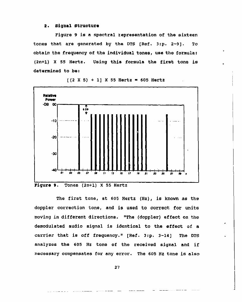
2. Signal Structure
Figure 9 is a spectral representation of the sixteen
tones that are generated by the DTS [Ref. 3:p. 2-9]. To
obtain the frequency of the individual tones, use the formula:
(2n+1) X 55 Hertz. Using this formula the first tone is
determined to be:
((2 X 5) + 1] X 55 Hertz = 605 Hertz
Aela vPower
.DB 0
I DO
-10
.20
.30
of W 05 0 00 o f 13 IS I? to D 3 i ? to
Figure 9. Tones (2n+1) X 55 Hertz
The first tone, at 605 Hertz (Hz), is known as the
doppler correction tone, and is used to correct for units
moving in different directions. "The (doppler) effect on the
demodulated audio signal is identical to the effect of' a
carrier that is off frequency." [Ref. 3:p. 3-14] The DTS
analyzes the 605 Hz tone of the received signal and if
necessary compensates for any error. The 605 Hz tone is also
27

phase continuous (it does not shift phases). Since it remains
phase continuous it does not carry any digital data. This
tone is always o dB higher than the other tones.
The last tone, 2915 Hz, is used for two purposes.
First, it is trigonometrically added to the 605 Hz tone to
create the preamble signal. Only the first and last tones are
transmitted during the preamble signal as illustrated in
Figure 10 [Ref. 3:p. 2-7]. To generate the preamble signal
the angle of the 605 tone is held constant and the angle of
the 2915 tone is shifted 180 degrees at the boundary of the
five preamble frames. The 2915 Hz tone is also used to encode
digital data using quadrature phase shift keying (QPSK).
RelativePower
•DB 00
.10
.20
.30
-40 - -
605 2915Frequency (Hertz)
Figure 10. Preamble: The First and Last Tones
28

In summary the first tone is used as a reference to
determine any doppler shift and generate the preamble signal.
Tones two through fifteen are used exclusively to encode
digital data with QPSK. Tone sixteen is used to generate the
preamble signal and to encode digital data with QPSK.
3. Binary Encoding
The two-digit binary representation of the phase shift
of each of the fifteen data tones allows for the
representation of a thirty-bit binary word. An example of the
thirty-bit binary word and its corresponding tones is shown in
Figure 11 [Ref. 3:p. 2-11]. The thirty-bit word represents
digital information that the DTS decodes and uses, or passes
through the crypto device to the NTDS computer. Whether the
DTS uses the information for net operation or passes the
information depends on what types of frames they are.
Hamming Parity Data Word(6 bits) , (24 bits)
I A
Bit I L 2 27L 2 2 _ 92 2 1t20 11617 1 32 0
26 21 20 19 18 1? 16 15 14 13 12 11 10 9 a LINK 1
Figure 11. Thirty-bit Data Frame construction
B. LINK-11 PROTOCOL
All information exchanged over the Link-11 net is encoded
into frames. The Link-11 net can operate at two different
29

data rates. These data rates are determined by two frame
times that support the Link-il net. The fast data rate
operates at 75 frames per second or 2250 bits per second
(bps). The slow data rate operates at 45.45 frames per second
or approximately 1364 bps. (Ref. 3:p. 2-2]
The data frames contain the tactical information that NTDS
computers are exchanging. The other frames, presented in
Figure 12, manage the operation of the net and allow the net
to operate automatically once initiated. The frames that are
not data frames are not encrypted and are generated within the
DTS. These frames are composed of preamble frames, a phase
reference frame and control codes as illustrated in Figure 12
[Ref. 4:p. 3-3).
Bringing together the previous sections of this chapter,
the formation of the Link-l1 information signal can be
understood. Figure 12 illustrates the composition of the
signal in time, whereas Figures 6 and 9 illustrate the
spectral representations. So, at each frame boundary in time
their is a change in data that is represented by a phase
change of tones two through sixteen. Using QPSK, the fifteen
tones make up thirty-bit words that change with the beginning
of every frame.
1. Link-li Frames
At the beginning of each transmission are five
preamble frames. The preamble frames are sent to alert
30
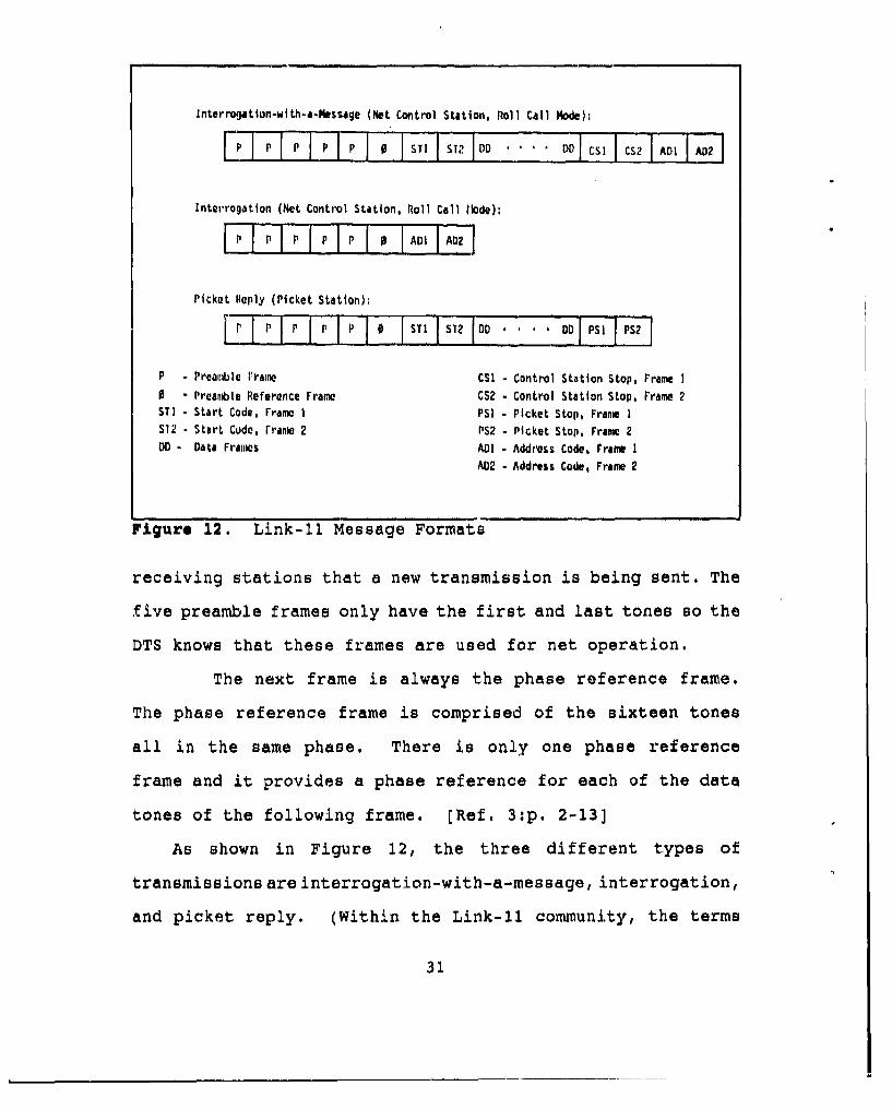
Interrogation-with-a-Nessage (Net Control Station, Roll Call Node):
P PP p 0 S I ST DD . . . CDD I CS7 I0 A
Interrogation (Net Control Station, Roll Call iode):
IP I P- P I P IP 1 0 AD A0
Picket Reply (Picket Station):
P P P P P 0 STi SI DD DO PSI PS2
P - Preamlble Irame CSI- Control Station Stop, Frame I
0 - Preamble Reference Frame CS2 Control Station Stop, Frame 2STI - Start Code, Frame I PSI - Picket Stop, Frane IST2 - Start Cude, rrante 2 PS2 - Picket Stop, Frame 2
DD- Data Fralw ADo . Address Code, Frame I
A02- Address Code, Frame 2
Figure 12. Link-i1 Message Formats
receiving stations that a new transmission is being sent. The
five preamble frames only have the first and last tones so the
DTS knows that these frames are used for net operation.
The next frame is always the phase reference frame.
The phase reference frame is comprised of the sixteen tones
all in the same phase. There is only one phase reference
frame and it provides a phase reference for each of the data
tones of the following frame. (Ref. 3:p. 2-13)
As shown in Figure 12, the three different types of
transmissions are interrogation-with-a-message, interrogation,
and picket reply. (Within the Link-il community, the terms
31
Picket Station and Participating Unit (PU) are often used
interchangeably.) The first type of transmission, shown in
Figure 12, is when the Network Control Station (NCS) has
information to transmit to the other net participants. To
save time the NCS directly follows the data message with a
call-up or interrogation to the next unit in the link. The
second transmission in Figure 12 is simply a call-up to a unit
in the net to transmits its data. The third is the data
transmission from the called or interrogated participating
unit..
2. Control Codes
"The Link-il control codes are the start code, the
picket stop code, the control stop code, and the PU address
codes." (Ref. 3 :p. 2-13) The types of control codes that are
used will depend on the type of message that is being
transmitted. The control codes are transmitted with all
sixteen tones using QPSK to encode data onto tones two through
sixteen.
The start code is used whenever data is to be
transmitted and immediately follows the preamble reference
frame. The start code signals the DTS that message data is
following. The DTS then prepares to pass the message data to
the NTDS computer. The start code consist of two frames of
thirty-bit words.
32

The PU address code is used by the NCS to identify
which unit in the link will be next to transmit its message
data. As soon as a picket station receives its address code,
the picket station switches from receive to transmit and sends
its message data.
The control stop code is used only by the NCS and it
indicates the end of the data transmission. The control stop
code immediately follows the data transmission of the NCS.
Whenever a PU receives message data, it checks to see what
type of stop code is used. If the stop code is from the NCS,
then the PU checks to see if its address code follows. If the
address code is not the code of that PU, then the PU remains
in the receive mode and waits for next transmission.
The picket stop code is used only by PU's to indicate
the end of itL message data. When other PU's receive this
stop code, they prepare to receive another transmission.
Whenever NCS receives this code, it initiates an interrogation
message or an interrogation-with-a-message transmission.
3. Net Operation
If start code frames follow the phase reference frame,
then the DTS knows to pass the frames following them to the
NTDS computer and watch for stop code frames. The start code
frames and the two different types of stop code frames are
always made up of the same thirty-bit binary words. These
thirty bits are encoded into an octal representation of
33

information as illustrated in Figure 13.
000 = 0 Since the control codes have the same thirty-001 = 1010 = 2 bit words, then they also have the same octal011 = 3100 = 4 representations. Their octal representations101 = 5110 = 6 are illustrated in Figure 14.111 = 7
If the frames that followed the phase
Figure 13. reference frame were not the start code, thenOctalRepresentation the DTS knows they 're address codes. Theof BinaryDigits DTS will compare the address rode frames with
its own address code to determipe if its unit
is next to transmit information. Note that the frames used
for net operation do no contain Error Detection and Correction
(EDAC) bits (Hamming Codes). EDAC bits are only used with
binary words that are being passed to the NTDS computer.
77777 77777 71777 77777
Picket Stop Code
00000 00000 00000 00000
Control Stop Code
74506 04C77 54673 22342
Start Code
Figure 14. Octal Representation of Control Codes
34

After the start code frames are received, the DTS
knows that the message data frames are next. When these are
received, the DTS will decode the digital data from the analog
signal using the six EDAC bits to check for errors. The other
twenty-four bits represents the digital information that the
NTDS computers are exchanging.
These twenty-four bits are passed through the crypto
equipment to the NTDS computer. The twenty-four bits
represent eight octal digits. The NTDS computers use these
octal digits to denote the tactical data that is transferred
between the NTDS computers.
4. Net Cycle Time (NCT)
The NCT depends primarily on how many units are in the
net and in what order they are interrogated. The net cycle is
entirely at the discretion of and determined by the NCS. When
initializing the net, operators on board the NCS enter the
sequential order of the net into their DTS. The operator can
enter the participating units in any order desired. The
operator also can enter units into the cycle twice. This
allows technologically advanced or "high value" units to be
polled more often. The drawback of this is that it increases
the NCT, and the other picket units that may have vital
information are not polled as often. To ensure an efficient
net the NCS needs to weigh these factors when determining the
order of the net.
35

C. RADZO EQUIPMENT
Link-t1 communications equipment provides a point-to-point
exchange of tactical digital information among Link-l1 users.
This equipment may be a transmitter/receiver configuration
with the equipment conducting independent operations; or, a
radio may functin interdependently containing both the
transmission and receiving functions. These interdependent
radios are called transceivers. [Ref. 3:p. 1-28)
Radios used for Link-l1 must meet requirements that are
different from radios designed for voice-only operations.
Link-li radios must have a quick transmit-to-receive switching
time. The transmitter must be keyed before the data arrives.
To do this transceivers must be able to key up for
transmission within milliseconds. "Because of the speed at
which the link operates, all link communication equipment must
be able to keep up with the repetitive cycles of transmission
and reception." [Ref. 3:p. 1-30]
1. HP Communications
"HF radios use a modulation technique called Amplitude
Modulation (AM) in which the Link-ti (baseband) audio signal
is used to modulate, or vary, the amplitude of the carrier."
These radios may operate in several different modes. For
HF Link-l1 operations, the Independent Side Band Suppressed
Carrier (ISBSC) and the Single Side Band Suppressed Carrier
(SSBSC) mode is available. In the ISBSC mode the carrier
36

frequency is suppressed and the tactical data information is
supplied to the Upper Side Band (USB) and the Lower Side Band
(LSB) for transmission as illustrated in Figure 15. [Ref. 3:p.
1-31]
As shown in Figure 15, each side band carries the same
information consisting of all sixteen tones. When operating
in the ISBSC mode the exact same information is applied to
both side bands. Using ISBSC the receiving stations has a
better capability of receiving an accurate signal. When
operating in the dual side band mode, "the receiving unit can
automatically select the best data from the upper side band,
the lower side band, or the diversity." [Ref. 3:p.1-32)
Link-l1 HF operations are normally conducted in the
dual side band setting, with the data terminal operating in
the diversity mode. Communications can be accomplished using
the single side band (SSBSC) mode but this is not attempted
often since there is no redundancy of the signal. Single side
band operation is only available in the upper side band mode.
[Ref. 2:p. 111-4]
2. UHF Communications
The Navy's UHF radios use a modulation technique
called Frequency Modulation (FM). An example of AM and FM is
illustrated in Figure 16 [Ref. 3:p. 1-34]. "This technique of
modulation is more resistant to interference than the
technique of amplitude modulation." [Ref. 3 :p. 1-33] Since FM
37

Lower UpprSO BSam Side bfl
C41
Figure 15. Independent Side Band Suppressed Carrier (ISBSC)
is more resistant to interference, the Navy's UHF radios
produce clearer signals. And since UHF is line-of-sight, a
measure of protection from signal exploitation can be obtained
when operating Link-li in UHF. [Ref. 2:p. 111-5]
The primary disadvantage of UHF is that it is limited
in range to line-of-sight. Unfortunately, UHF communications
can only be employed when force size and separation permit.
Transmissions from surface units under normal propagation
conditions are limited to line-of-sight ranges on the order of
20 to 30 miles. The actual transmission ranges will vary
depending on the height of the transmitting and receiving
antennas and the existing propagation conditions.
38
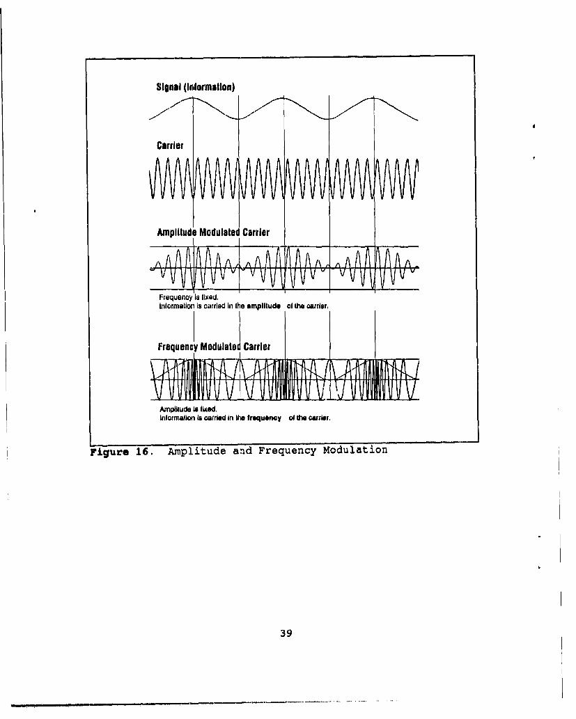
Signal (information)
Carrier
Amplit Modulated Carrier
Frequency is fixed.Inlormalion Is carried in the amplituds of the carrier,
Frequency Modulate Carrier
Amplllude i fixed.Inlormalion is carried in he frequenoy of th carrier,
Figure 16. Amplitude and Frequency Modulation
39
V. SYSTEM MANAGEMENT
"Net management is the activity of planning, monitoring,
and adjusting assignments, functions, parameters, and
participation within the net." Some of the things that need
to be considered in managing the Link-l1 net are which unit
should be the Net Control Station (NCS), what frequency to use
and when, and how to analyze the efficiency of the net. (Ref.
3:p. 5-1]
The selection of the NCS can have an effect on the entire
Link-li net. The position of the NCS should be in the ideal
location to assure communications with every other Link-il
unit. If the NCS is in a position where one or more units are
not in communication with it, then those units will not
receive the signal for them to transmit. If this occurs then
the other units in the net will not receive the tactical data
of the units that were left out.
The equipment capabilities of the NCS also can have a
significant effect on the usefulness of the Link-il net. If
the NCS has a degraded receiver, the NCS Data Terminal Set
(DTS) may not realize another station is transmitting its
data. Consequently the NCS will neutralize the tactical data
from those participation units (PU) and degrade the entire
net. [Ref. 3:p. 5-4]
40

A. FREQUENCY KMRNAGEMENT
There are several factors that determine the optimum
frequency for a given situation. The first and foremost is
distance. The short UHF line-of-sight range does not allow
its use among surface units in a dispersed force. An
exception to this is when an airborne Liak-11 unit is used as
the NCS. The airborne unit may be employed to provide a
tactical picture to surface units over a large area. "During
surface EMCON khe surface force can operate in the radio
silent mode (receive only) utilizing the tactical picture
provided by the airborne TDS units." [Ref. 2:p. 111-5)
Although HF can be used for greater distances than UHF,
there are many factors that influence the propagation of the
HF signal. One variable is the ground wave range of different
HF frequencies. "For example, a 1000-watt transmitter at 2
MHz will have a (ground wave) range of 350 miles. The same
transmitter at 30 MHz will have a (ground wave) range of 90
miles." [Ref. 3:p. 5-7)
Another factor that affects HF propagation is the
ionosphere. The ionosphere makes up a portion of the
atmosphere that is between 50 and 200 miles above the earth.
"This region contains ions and electrons in numbers large
enough to affect the direction of radio wave travel." (Ref.
3:p. 3-16) The density of the ions and electrons in the
ionosphere make a significant impact on the sky wave component
of a HF signal. Since the beginning of the ionosphere starts
41

at an altitude of 50 miles, it has a lesser effect on the
ground wave component of a HF signal.
Ultraviolet radiation from the sun increases the amount of
ionization in the atmosphere. During the day the ionosphere
is composed of the D, E, F1, and F2 layers as shown in Figure
17 [Ref. 3:p. 3-17]. At night the D and E layers disappear,
and the F1 and F2 layers combine into the F layer. The
ionosphere has more layers and is denser during daylight
hours. When the ionosphere is denser it has a greater
tendency to refract HF radio waves. When the ionosphere is
dense it also has a tendency to absorb radio waves, thus
reducing communication ranges.
The ionosphere affects each frequency differently. As
Figure 17 shows, different frequencies are refracted at
different heights. The degree of refraction will depend on
the density of the layers and the frequency of the radio wave.
Layer density varies with the time of day. At noon when the
sun is directly overhead, all four layers are at their
densest. At sunrise and sunset the layer density is difficult
to establish. The D and E layers are barely discernable and
the F layer is in transition. The density of the ionosphere
is at its least at night when only the F layer exists.
The higher the frequency the lessor the ionosphere affects
it. During daylight hours the D layer acts as a "sponge"
absorbing lower frequencies that try to pass through it. This
phenomenon virtually eliminates the sky wave component of
42

'n h f a t a ',ct. d eu to v eu"
Figure a s7 Ionosphere Layers During Daylight Hours
lower frequency signals. At night, when the ionosphere is
thinner, higher frequencies are not refracted enough to return
to earth and pass through the ionosphere. Again the sky wave
component is essentially nullified. Figure 18 illustrates the
usable frequencies in relation to the time of day. [Ref. 3:p.
5-9]
"Changing the Link-il frequency is at times unavoidable
because of weather, atmospherics, and/or interference." When
conditions require a change, it must be made as swiftly as
possible to secure a smooth change of frequencies. Other
units may advise the net coordinator of the quality of its
43

24 -
24
26
igu 4 18. MaiubUabeFrq e MF n oetUal
20
is
14
12
6
4
2
S1 8 W u eNon sur et o. j
Figure 18. Maximum Usable Frequency (MUF)'and Lowest "Usable'
Frequency (LUF)
communications, but the net coordinator is responsible for the
overall Link-li performance.
B. SIGNAL EXPLOITATION/JAMM4ING
"A Link-il net operating in the HF spectrum is
significantly more vulnerable to signal exploitation by
hostile forces operation beyond the local horizon than a Link-
11 net operating in the UHF spectrum." Although the HF ground
wave can be detected out to about 300 miles, the potential sky
wave range of over one thousand miles makes HF extremely
vulnerable to intercept and Direction Finding (DF). Limited
44

Range Intercept (LRI) techniques should be considered when
practical. [Ref. 2:p. 111-5]
"HF is probably the frequency band most susceptible to
jamming. Jammers located far from the receiver are known to
be able to jam/disrupt HF reception, particularly when
operating via sky wave propagation." [Ref. 1:p. 2-20] Nuclear
blackouts present another potential liability to HF sky waves.
They are most vulnerable to nuclear blackout resulting from
high altitude nuclear burst. It is expected that HF sky wave
communications could be lost for several hours or even days in
a nuclear environment. Although the effects of nuclear blasts
have a significant effect on HF sky waves, the groundwave
portions of HF communications are not affected and normal
propagation ranges can be expected. [Ref. 1:p. 2-20]
UHF is less susceptible to jamming since the jamming
station must be within line-of-sight (LOS) of the receiving
station. UHF is also less vulnerable to nuclear blackouts,
with a loss of communication expected to last only a few
seconds.
C. RECEPTION QUALITY
"Reception Quality, or (RQ), is a numeric value measuring
the ability of every ship to receive every other ship." [Ref.
3:p. 4-29] The RQ values are used by net operators to monitor
the Link-t1 net. RQ values vary from one to seven with seven
45
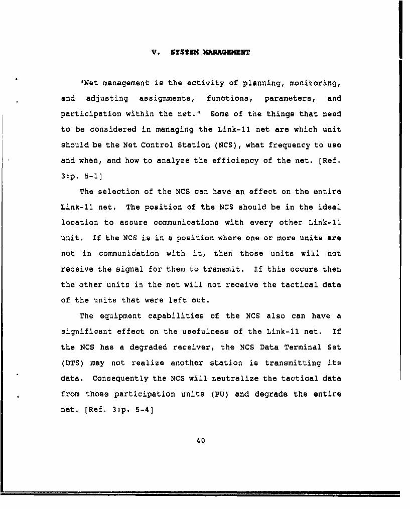
representing the highest degree of communications quality.
Figure 19 shows the breakdown of RQ values. (Ref. 3:p. 4-29)
7 None 93 -100%6 None 79 - 92%5 None 65 - 78%4 None 50 - 64%3 None 36 - 49%2 None 22 - 35%1 None 7 - 21%%-
Figure 19, Reception Quality (RQ) Values
A RQ value of seven indicates that all data frames
transmitted by that PU have been received with minimal
detected errors. The net coordinator should closely monitor
any unit with a RQ value lass than five. If a unit
consistently has a RQ value less than five then the net
operators know the net is degrading and an analysis and/or a
change may be necessary.
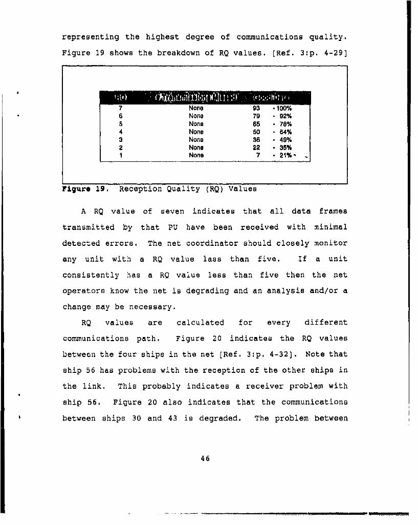
RQ values are calculated for every different
communications path. Figure 20 indicates the RQ values
between the four ships in the net [Ref. 3:p. 4-32). Note that
ship 56 has problems with the reception of the other ships in
the link. This probably indicates a receiver problem with
ship 56. Figure 20 also indicates that the communications
between ships 30 and 43 is degraded. The problem between
46

ships 30 and 43 may be because of distance, since the
communications with other ships in the net is adequate.
A7 ~ 30 6~
2
6 2
7 362 56
7 4
3
6 7
43
Figure 20. RQ Values of a Link-l1 Net
By nature, communication circuits are difficult to analyze
without complicated equipment and a technical knowledge of
electronics. For communicators to adequately support Link-il,
they need to be familiar with'all aspects of net operations.
They need to know all the equipment that is used for the net
and that this equipment is being properly maintained.
Although some of this Link-il equipment is not under their
47

control, communicators should periodically -heck to ensure
that the entire circuit is in excellent condition.
48

VI. CONCLUSION
In the 1960's and 1970's, the over-the-horizon threat was
limited to a few hundred miles. Link-li was developed to
counter this threat. "When operating in the HF band, Link-li
provides gapless omni-directional coverage of up to 300
nautical miles from the transmitting site." [Ref. 3:p. 1-2]
But today weapons systems are faster and have a range of
several hundred miles. With a data rate that is low (2250
bps) compared to today's standards, the Link-il system is
struggling to keep pace with new technology.
Some existing telecommunications technologies were
reviewed to see if any of them could possibly be used for
redundancy and/or alternate path communications. These
systems include Officer-in-Tactical-Command Information
Exchange System (OTCIXS), satellite communications, and Demand
Assigned Multiple Access (DAMA).
A. OTCI1S
OTCIXS is a two-way UHF satellite communications network.
It is designed to support the Officer-in-Tactical-Command
(OTC) of a battle group. This system is used to reduce
message traffic over the satellite broadcast. It provides the
OTC with a satellite network that is exclusive to the battle
49

group. "The network will support ship-to-ship high speed
teletypewriter and tactical record (communications) ...
including event-by-event track updates and ... narrative
traffic." [Ref. l:p. 5-38]
Although OTCIXS is a data exchange network and is actually
capable of transferring data at a significantly higher rate,
the Link-ti system needs a dedicated circuit to operate on.
Without this dedicated circuit, Link-il will not be able to
provide accurate up-to-date contact information to net
participants. There is also a satellite interface problem
that is described below.
B. DANA
DAMA is a Time Division Multiplexed (TDM) signal that is
used in satellite transmissions. TDM is a method of time-
integrating samples of several signals onto one radio
frequency carrier, each assigned to unique time slots. The
DAMA configuration of TDM then uses digital burst
transmissions to get a cycle of information into a smaller
time slot. Figure 21 shows an example of TDM time slots.
Theoretically, Link-il can operate on DAMA just like other
communication circuits are capable of doing. But there are
specific net operating functions that prevent Link-il from
operating with any satellite signal. This unique problem
occurs during routine operation of the Link-il net.
50

Time Slot #. I Time Slot #2
Freq *1 Frecq #2 1Freq #3 1Freq #4 Preq #1 1Freq #27
DAMA Signal
Freq #1 (slot #1) Freq #1 (slot #2)
Freq #2 (slot #1)
Figure 21. DAMA Time Slots
The Net Control Station (NCS) interrogates other ships to
query them for messages. After sending an interrogation
message, the NCS waits fifteen frames for a response. If a
response is not received within the fifteen frames, then the
NCS continues with the operation of the net. Since the Link-
11 net is operated around a 300 miles radius, ships have
plenty of time to respond to the interrogation from the NCS.
But if Link-l was operated through a satellite, the NCS would
not receive a response within the fifteen frames. So, for
Link-li to operate on any satellite communications system,
there would have to be equipment modifications to all the
Link-li ships.
51

C. SUMNARY
Link-li was designed to provide battle group commanders
with real time tactical information from and to all their
ships and aircraft within 300 nautical miles. Each ship and
aircraft has its sensors continuously feeding contact
information to its NTDS computer. Thus, the system enables
each platform in the net to exchange tactical information over
communication circuits using computer automation. Once
initiated the Link-li net operates automatically without
manual intervention.
A specific protocol is used for the operation of Link-11.
Within this protocol, certain codes are used to inform each
individual platform when to transmit and when to receive
tactical data. The system uses Quadrature Phase Shift Keying
to encode the tactical data onto the radio frequency carrier.
Link-li is the best close-in tactical information exchange
system the Navy has. With the present equipment
configurations, Link-il is not compatible for operations with
or on any satellite networks. However, satellite networks
(i.e., OTCIXS) do complement Link-li in providing long range
tactical information.
52

LIST OF REFERENCES
1. Defense Intellegence Agency, Communications Handout forIntellegence Planners(U), 1986. (SECRET Document)
2. Navy Tactical Interoperability Support Activity, Lifl1z/TADIL-A Standard operating Procedures/ODerating Manual(U)OPNAVINST C3120.39B. (CONFIDENTIAL Document)
3. Navy Sea Systems Command, Understanding Link-li, Logicon,Inc., 1991.
4. Naval Electronics Systems Engineering Center, nicalManual Operation and Maintenance Instruction for DTSAN/UO-76(V)2, 1984.
5. Stanley, William D., Electronic Communications Systems,Prentice Hall, Inc., 1982.
53

INITIAL DISTRIBUTION LIST
Defense Technical Information Center 2Cameron StationAlexandria, VA 22304-6145
Library, Code 52 2Naval Postgraduate SchoolMonterey, CA 93943-5002
Chairman, Code ASIDepartment of Administrative SciencesNaval Postgraduate SchoolMonterey, CA 93943-5000
Prof. Dan C. Boger, Code AS/BOIDepartment of Administrative SciencesNaval Postgraduate SchoolMonterey, CA 93943-5000
MAJ Thomas A. Schwendtner, Code EC/SCDepartment of Administrative SciencesNaval Postgraduate SchoolMonterey, CA 93943-5000
Officer-in-Charge1Communications SchoolNETCNewport, RI 02840 -
Accesioti ForLT Thor A. Simensen NI R&1318 S. Schueber Road NIS CAW ECentrailia WA 98531 ULiTA
Jjuttificatiol ....................
By ..............................
Diet KQ~fi ~id/or
Dit Special
54