LINETRAXX® RCMS150 series - Bender
52
Manual EN LINETRAXX® RCMS150 series Residual current monitor type B with integrated measuring current transformers for earthed AC/DC systems (TN and TT systems) RCMS150_D00259_01_M_XXEN/08.2021
Transcript of LINETRAXX® RCMS150 series - Bender

Manual EN
LINETRAXX® RCMS150 series
Residual current monitor type Bwith integrated measuring current transformers forearthed AC/DC systems (TN and TT systems)
RCMS150_D00259_01_M_XXEN/08.2021

Bender GmbH & Co. KGLondorfer Str. 65 • 35305 Grünberg • DeutschlandPO Box 1161 • 35301 Grünberg • DeutschlandTel.: +49 6401 807-0 • Fax: +49 6401 807-259Email: [email protected] • www.bender.de
© Bender GmbH & Co. KG
All rights reserved.Reprinting only with permission of the publisher.Subject to change!Photos: Bender archives

Table of Contents
1. Important information ........................................................................... 5
1.1 How to use this manual ................................................................................... 5
1.2 Technical support: service and support .................................................... 6
1.2.1 First level support .............................................................................................. 6
1.2.2 Repair service ...................................................................................................... 6
1.2.3 Field service ......................................................................................................... 6
1.3 Training courses ................................................................................................. 7
1.4 Delivery conditions ........................................................................................... 7
1.5 Inspection, transport and storage ............................................................... 7
1.6 Warranty and liability ....................................................................................... 8
1.7 Disposal ................................................................................................................. 8
2. Safety instructions .................................................................................. 9
2.1 General safety instructions ............................................................................ 9
2.2 Work activities on electrical installations .................................................. 9
2.3 Intended use ..................................................................................................... 10
3. Product description ............................................................................. 11
3.1 Device features ................................................................................................. 11
3.2 Functional description ................................................................................... 11
3.3 Approvals and certifications ........................................................................ 12
4. Mounting, connection and commissioning .................................... 13
4.1 Mounting the device ...................................................................................... 13
4.1.1 Important information on mounting ....................................................... 13
4.1.2 Type of mounting ............................................................................................ 14
4.1.3 Dimension diagram (mm) ............................................................................ 14
4.2 Connecting the device .................................................................................. 14
4.2.1 Display and operating elements ................................................................ 15
3RCMS150_D00259_01_M_XXEN/08.2021

Table of Contents
4.3 Wiring diagram ................................................................................................. 16
4.4 Commissioning ................................................................................................ 18
5. Display via web server ......................................................................... 20
5.1 Example of a system design ........................................................................ 20
5.2 Starting the web browser ............................................................................. 20
5.3 User interface web browser ......................................................................... 20
5.4 Web application: Menu overviews .......................................................... 21
6. Overview Modbus registers (RCMS150-01 only) ............................ 24
6.1 General overview ............................................................................................. 24
6.1.1 Read and write permissions ......................................................................... 24
6.1.2 Used formats ..................................................................................................... 24
6.1.3 Overview of the register ranges ................................................................. 25
6.2 Device information ....................................................................................... 25
6.3 Measured values ............................................................................................. 27
6.4 Interface parameters ...................................................................................... 32
6.5 Parameters ........................................................................................................ 33
6.6 Control commands ........................................................................................ 38
7. Glossary ................................................................................................... 40
8. Technical data ........................................................................................ 43
8.1 Tabular data ....................................................................................................... 43
8.2 Factory settings of the Modbus interface ............................................... 46
8.3 Standards, approvals, certifications .......................................................... 46
8.4 Ordering information ..................................................................................... 46
8.5 Document revision history ........................................................................... 47
INDEX ............................................................................................................ 49
4 RCMS150_D00259_01_M_XXEN/08.2021

Important information
1. Important information
1.1 How to use this manual
Always keep this manual within easy reach for future reference. To make it easier for you to understand and revisit certain sections in this manual, we have used symbols to identify important instructions and information. The meaning of these symbols is explained below:
This manual has been compiled with great care. It might nevertheless contain errors and mistakes. Bender cannot accept any liability for injury to persons or damage to property resulting from errors or mistakes in this manual.
This manual is intended for qualified personnel working in electricalengineering and electronics!
This signal word indicates that there is a high risk of danger that willresult in electrocution or serious injury if not avoided.
This signal word indicates a medium risk of danger that can lead todeath or serious injury, if not avoided.
This signal word indicates a low level risk that will result in minor ormoderate injury or damage to property if not avoided.
This symbol denotes information intended to assist the user in makingoptimum use of the product.
DANGER
WARNING
CAUTION
5RCMS150_D00259_01_M_XXEN/08.2021

Important information
1.2 Technical support: service and supportFor commissioning and troubleshooting Bender offers you:
1.2.1 First level supportTechnical support by phone or e-mail for all Bender products Questions concerning specific customer applications Commissioning Troubleshooting
Telephone: +49 6401 807-760*Fax: +49 6401 807-259In Germany only: 0700BenderHelp (Tel. and Fax)E-mail: [email protected]
1.2.2 Repair serviceRepair, calibration, update and replacement service for Bender products Repairing, calibrating, testing and analysing Bender products Hardware and software update for Bender devices Delivery of replacement devices in the event of faulty or incorrectly delivered
Bender devices Extended guarantee for Bender devices, which includes an in-house repair service
or replacement devices at no extra cost
Telephone: +49 6401 807-780** (technical issues)+49 6401 807-784**, -785** (sales)
Fax: +49 6401 807-789E-mail: [email protected] send the devices for repair to the following address:
Bender GmbH, Repair-Service, Londorfer Straße 65, 35305 Grünberg
1.2.3 Field serviceOn-site service for all Bender products Commissioning, configuring, maintenance, troubleshooting for Bender products Analysis of the electrical installation in the building (power quality test, EMC test,
thermography) Training courses for customers
6 RCMS150_D00259_01_M_XXEN/08.2021

Important information
Telephone: +49 6401 807-752**, -762 **(technical issues)+49 6401 807-753** (sales)
Fax: +49 6401 807-759E-mail: [email protected]: www.bender.de
*Available from 7.00 a.m. to 8.00 p.m. 365 days a year (CET/UTC+1)**Mo-Thu 7.00 a.m. - 8.00 p.m., Fr 7.00 a.m. - 13.00 p.m.
1.3 Training coursesBender is happy to provide training regarding the use of test equipment. The dates of training courses and workshops can be found on the Internet at www.bender.de > Know-how > Seminars.
1.4 Delivery conditionsBender sale and delivery conditions apply. For software products the "Softwareklausel zur Überlassung von Standard-Software als Teil von Lieferungen, Ergänzung und Änderung der Allgemeinen Lieferbedingungen für Erzeugnisse und Leistungen der Elektroindustrie" (software clause in respect of the licensing of standard software as part of deliveries, modifications and changes to gen-eral delivery conditions for products and services in the electrical industry) set out by the ZVEI (Zentralverband Elektrotechnik- und Elektronikindustrie e. V.) (German Electri-cal and Electronic Manufacturer's Association) also applies.Sale and delivery conditions can be obtained from Bender in printed or electronic for-mat.
1.5 Inspection, transport and storageInspect the dispatch and equipment packaging for damage, and compare the contents of the package with the delivery documents. In the event of damage in transit, please contact Bender immediately.The devices must only be stored in areas where they are protected from dust, damp, and spray and dripping water, and in which the specified storage temperatures can be ensured.
7RCMS150_D00259_01_M_XXEN/08.2021

Important information
1.6 Warranty and liabilityWarranty and liability claims in the event of injury to persons or damage to property are excluded if they can be attributed to one or more of the following causes: Improper use of the device. Incorrect mounting, commissioning, operation and maintenance of the device. Failure to observe the instructions in this operating manual regarding transport,
commissioning, operation and maintenance of the device. Unauthorised changes to the device made by parties other than the manufac-
turer. Non-observance of technical data. Repairs carried out incorrectly and the use of replacement parts or accessories not
approved by the manufacturer. Catastrophes caused by external influences and force majeure. Mounting and installation with device combinations not recommended by the
manufacturer.This operating manual, especially the safety instructions, must be observed by all per-sonnel working on the device. Furthermore, the rules and regulations that apply for ac-cident prevention at the place of use must be observed.
1.7 DisposalAbide by the national regulations and laws governing the disposal of this device. Ask your supplier if you are not sure how to dispose of the old equipment. The directive on waste electrical and electronic equipment (WEEE directive) and the di-rective on the restriction of certain hazardous substances in electrical and electronic equipment (RoHS directive) apply in the European Community. In Germany, these pol-icies are implemented through the "Electrical and Electronic Equipment Act" (ElektroG). According to this, the following applies: Electrical and electronic equipment are not part of household waste. Batteries and accumulators are not part of household waste and must be dis-
posed of in accordance with the regulations. Old electrical and electronic equipment from users other than private households
which was introduced to the market after 13 August 2005 must be taken back by the manufacturer and disposed of properly.
For more information on the disposal of Bender devices, refer to our homepage at www.bender.de > Service & support.
8 RCMS150_D00259_01_M_XXEN/08.2021

Safety instructions
2. Safety instructions
2.1 General safety instructionsPart of the device documentation in addition to this manual is the enclosed "Safety in-structions for Bender products".
2.2 Work activities on electrical installations
If the device is used outside the Federal Republic of Germany, the applicable local standards and regulations must be complied with. The European standard EN 50110 can be used as a guide.
Only qualified personnel are permitted to carry out the work necessaryto install, commission and run a device or system.
Risk of electrocution due to electric shock!Touching live parts of the system carries the risk of: An electric shock Damage to the electrical installation Destruction of the device Before installing and connecting the device, make sure that theinstallation has been de-energised. Observe the rules for working onelectrical installations.
DANGER
9RCMS150_D00259_01_M_XXEN/08.2021

Safety instructions
2.3 Intended useThe RCMS150… devices are suitable for measuring residual currents up to IΔ = 500 mA in a frequency range of DC…2 kHz. The monitored circuit is rated for a voltage of 300 V and a load current of 32 A. If cables with double or reinforced insulation are routed through the measuring current transformers, higher voltages may occur. The device can be operated at an altitude of up to 2000 m above mean sea level.In order to meet the requirements of applicable standards, customised parameter set-tings must be made on the equipment in order to adapt it to local equipment and op-erating conditions. Please heed the limits of the range of application indicated in the technical data.
Any other use than that described in this manual is regarded as improper.
10 RCMS150_D00259_01_M_XXEN/08.2021

Product description
3. Product description
3.1 Device features Continuous residual current monitoring by means of periodic verification AC/DC sensitive residual current monitoring system type B with 6 channels K1…6
(each channel features 2 measuring channels: 1 x RMS, 1 x DC) Ideal for applications with space limitations Easy DIN rail or screw mounting to standard distribution panels 2 separately adjustable response values (DC or RMS) per channel Continuous self monitoring Fully shielded measuring current transformers to avoid external influences due to
magnetic fields that may cause disturbances Compatible with Bender gateways of type COM465IP or CP9… RCMS150 (RS-485 interface with BMS protocol)
– Compatible with RCMS460/490 in a system setup– Address range 2…90, can be adjusted directly on the device – Up to 89 RCMS150 can be used on the bus
RCMS150-01 (RS-485 interface with Modbus RTU protocol)– Compatible with other Modbus RTU-capable device series from Bender, such
as the RCMB300 series and RCMB13…-01 in a system setup– Address range 1…99, can be adjusted directly on the device via detent poten-
tiometers – Address range 1…247, can be adjusted via the bus– Up to 247 RCMS150-01 can be used on the bus
3.2 Functional descriptionThe residual currents are recorded and evaluated as RMS values in the frequency range DC…2 kHz. The response values can be set via the interface. The user can set four response values per channel K1…6:
IΔn1 RMS , IΔn2 RMS, IΔn1 DC, IΔn2 DC
The response values IΔn1… apply to the prewarnings, the response values IΔn2… apply to the main alarms.
11RCMS150_D00259_01_M_XXEN/08.2021
Product description
If one of the four set response values IΔN… is exceeded, the assigned response delay ton… starts. If the response value continues to be exceeded, the corresponding alarm message (prewarning or main alarm) is indicated on the gateway after the response de-lay ton… has elapsed. In the event of a main alarm, the alarm LED of the respective channel K1…6 lights up yellow.
A pending alarm message is emitted via the BMS or Modbus interface with address and measuring channel indication and can be evaluated by means of a gateway.
If the recorded residual current falls below the release value (response value minus hys-teresis) the delay on release toff begins. If the value remains below the release value af-ter toff has elapsed, the LED of the respective channel goes out. The alarm message is reset on the interface. If the fault memory is enabled (only applicable to RCMS150-01), the alarm message re-mains on the bus despite the LED going out.
All devices can be accessed via the network from any PC using a standard web browser. Like this, all relevant measurement data of the monitored system are available. All de-vice-related parameters of the RCMS150… can be set via the gateway technology.
To ensure the device function, a continuous automatic self test is run, which monitors the function of all measuring current transformers. In the event of a device error, the alarm LED of the respective channel flashes and an error message is output via the in-terface.
During the manual self test, a residual current is induced in the respective current trans-former at each individual channel K1…6 one after the other via test windings and it is checked whether the corresponding main alarm is triggered. The duration of the test depends on the response delays of the main alarms.
3.3 Approvals and certifications UL508 in preparation CSA in preparation LR in preparation
12 RCMS150_D00259_01_M_XXEN/08.2021

Mounting, connection and commissioning
4. Mounting, connection and commissioning
4.1 Mounting the device
4.1.1 Important information on mounting Mounting is to be carried out with suitable equipment and tools according to the
documentation. The device must only be installed by appropriately qualified personnel in de-
energised state. Disconnect the switchboard cabinet from the power supply and protect the system against accidental switch-on.
The general safety conditions as well as the prevailing national accident preven-tion regulations are to be adhered to. Electrical installation is to be carried out according to all applicable local laws (e.g. wire cross section, protection, PE con-nection).
The climatic conditions must be complied with. The device is only permitted to be used in closed rooms.
Only qualified personnel are permitted to carry out the work necessaryto install, commission and run a device or system.
Risk of electrocution due to electric shock!Touching live parts of the system carries the risk of: An electric shock Damage to the electrical installation Destruction of the device Before installing and connecting the device, make sure that theinstallation has been de-energised. Observe the rules for working onelectrical installations.
If you are familiar with the configuration of computer networks, you canconnect the RCMS150… yourself. Otherwise please contact your EDP administrator!
DANGER
13RCMS150_D00259_01_M_XXEN/08.2021

Mounting, connection and commissioning
4.1.2 Type of mountingThe devices of the RCMS150 series are intended for screw mounting. As an alternative, they can also be mounted on a DIN rail using the optionally available fastening set.
4.1.3 Dimension diagram (mm)
Fig. 4.1: Dimension diagram RCMS150
4.2 Connecting the device
Risk of electric shock!Follow the basic safety rules when working with electricity. Observe theinformation on rated voltage and supply voltage specified in thetechnical data!
230
K1 K2 K3 K4 K5 K6
A B + -
24510
38
205
263
4
6
DANGER
14 RCMS150_D00259_01_M_XXEN/08.2021

Mounting, connection and commissioning
4.2.1 Display and operating elements
Fig. 4.2: Display and operating elements
Display and operating elements legend
1 Slot for screw mounting
2 Alarm LEDs for channels K1…6 (yellow)
3 Line feed-through of the measuring current transformers for the channels K1…6
4 ON LED: Power on LED (green)
5 Detent potentiometer: Setting the unit place of the bus address (BMS bus or Modbus RTU)
6 Detent potentiometer: Setting the tens place of the bus address (BMS bus or Modbus RTU)
7 Plug: Connection to the supply voltageConnection RS-485 (BMS bus or Modbus RTU)
RCMS150-01 If both detent potentiometers are set to 0, the device uses the addressparameterised via Modbus (1…247).
K1 K2 K3 K4 K5 K6ON/COM
012 3
4 5 6 789
x1
012 3
4 5 6 789 x10
A B + -
1 2 3 4 5
67
15RCMS150_D00259_01_M_XXEN/08.2021

Mounting, connection and commissioning
Meaning of the LEDs
Tab. 4.1: Description of the LEDs
4.3 Wiring diagram
LED Meaning
ON (green)
lights Normal operation indicator
flashes quicklyRCMS150: Device error or BMS bus address set incorrectly
flashes slowly RCMS150-01: Device error
flashes very quickly
RCMS150-01: Identify device (via Modbus RTU)
Flash code Interface address output (see page 19)
ALARM K1…K6 (yellow)
lights Main alarm (response value IΔn exceeded)
flashes Device error channel
Risk of short circuit!Only insulated conductors with an insulation that is suitable for at leastthe monitored voltage may be routed through the measuring currenttransformer. The rated voltage of the RCMS150… must not be exceeded.
CAUTION
16 RCMS150_D00259_01_M_XXEN/08.2021

Mounting, connection and commissioning
Fig. 4.3: Wiring diagram RCMS150…
Fig. 4.4: Detail: terminal
Detail: terminal
1 RS-485 interface (BMS bus or Modbus RTU)
2 Supply voltage US DC 24 V
3Terminating resistor 120 Ω (required for both the first and the last bus device)
K1 K2 K3 K4 K5 K6
#1 #2 #3 #4 #5 #6
ON/COM
0 1 2
3 4 5 6 7 8 9
0 1
2 3
4 5 6 7 8 9
A B +
x 1
x 10
PE
L1
L2
L3
N
PE
A B + -
A B +24V GND
1 2
3
17RCMS150_D00259_01_M_XXEN/08.2021

Mounting, connection and commissioning
4.4 Commissioning1. Mount the RCMS150…
2. Set the bus address
3. Bus installation
Please note that both the beginning and end of the bus require a 120-Ω terminat-ing resistor.
When assigning the bus addresses make sure that each address is onlyassigned once on the bus!
Address setting RCMS150 (BMS bus)
Factory setting bus address 2
Setting range BMS bus 2…90
Adjustment on the deviceMove the detent potentiometers to the corresponding position using a screwdriver.
Address setting RCMS150-01 (Modbus RTU)Factory setting bus address(Detent potentiometers to 00)
Last two digits of the serial number + 100
Setting range Modbus RTU 1…247
Addresses 1…99:Adjustment on the device
Move the detent potentiometers to the corresponding position using a screwdriver.
Addresses 1…247:Adjustment via the bus
Set the detent potentiometers to 00 using a screwdriver. Now the internally stored address (factory setting) is active. It can be changed via the interface.
18 RCMS150_D00259_01_M_XXEN/08.2021

Mounting, connection and commissioning
4. Route outgoing circuits to be monitored through the current transformers
5. Connect the RCMS150… to the supply voltage (DC 24 V)
RCMS150 (BMS bus)The ON LED flashes to indicate the set BMS bus address after the device has been switched on or after the address has been changed: Unit place - Pause - Tens place.Example: ***** *** designates the BMS bus address 35.After indicating the address, the RCMS150 automatically switches to the standard display state. If the ON LED flashes quickly, the BMS bus address has been set in-correctly.
RCMS150-01 (Modbus RTU)The set Modbus address is only indicated by the ON LED flashing after an address change via the detent potentiometers on the device: Hundreds place – Pause – Tens place – Pause – Unit place.Example: * ***** *** designates the Modbus address 153.After indicating the address, the RCMS150-01 automatically switches to the stand-ard display state. The ON LED does not indicate address changes via the bus.
6. Connect RCMS150… to master (e.g. COM465IP, software version ≥ 2.1, option C or CP9…).
Risk of short circuit!Only insulated conductors with an insulation that is suitable for at leastthe monitored voltage may be routed through the measuring currenttransformer. The rated voltage of the RCMS150… must not be exceeded.
Do not route any protective earth conductors through the measuringcurrent transformers (see wiring diagram)!
CAUTION
19RCMS150_D00259_01_M_XXEN/08.2021

Display via web server
5. Display via web server
The measured values (measuring channels) of the individual measuring current trans-formers of the RCMS150… can be displayed in the web browser.
5.1 Example of a system design
5.2 Starting the web browserAfter commissioning the RCMS150…, start the web browser. Enter the IP address of the gateway (CP9… or COM465IP).
BMS bus You can find the RCMS150 in the bus overview.Modbus RTU You can add the RCMS150-01 to your system in the browser:
Tools > Device management > Modbus devices > Manage devices > Add device > Search and configure devices
5.3 User interface web browserBasic operation: see manual of the gateway (CP9… or COM465IP).
COM465IPRCMS150
K1
K2
K3
K4
K5
K6
ON/COM
0123 4
5 6 7 89 x1
0123 4
5 6 7 89 x10
A B + -
120 Ω
120 Ω(DIP switch COM465IP)
20 RCMS150_D00259_01_M_XXEN/08.2021

Display via web server
5.4 Web application: Menu overviews
Tab. 5.1: Web application: Menu overview RCMS150
Menu overview RCMS150 (BMS bus) Description
OverviewCurrent measured values and alarm states of the 12 measuring channels (1…6: RMS; 7…12: DC)
Configure e-mail
Generate e-mails to report device failure. Set recipients via the gateway for each channel. Details: refer to gateway manual
Report Create a report of all active devices
Menu
Settings
Edit texts
DeviceScreen and printout: Specify alarm text for device and device failure
Channel1 - 12
Screen and printout:Specify alarm text for measuring channel 1…12 for prewarning and main alarm
Channel
General Channel K1…6: Hysteresis, toff, tstart-up
RMSChannel K1…6: ton1/2 RMS , IΔn1/2 RMS (measuring channels 1…6)
DCChannel K1…6: ton1/2 DC, IΔn1/2 DC (measuring channels 7…12)
Factory settingsReset to factory settings; texts are not affected by this action.
Control TEST Run device test
InfoDevice, software and manufacturer information
When setting the response values IΔn2, the ratio of IΔn2RMS to IΔn2DC must only be between 0.2 and 5.
21RCMS150_D00259_01_M_XXEN/08.2021

Display via web server
Menu overview RCMS150-01 (Modbus RTU) Description
Overview of the 12 measuring channelsCurrent measured values/alarm states, software
Alarms/meas-ured val-ues
Graphical representation K1…6, each IΔ RMS and IΔ DC
Settings
Edit texts
Device Alarm text device/device failure
Measuring channel 1…12
Description Alarm texts of the measuring channels in the event of a prewarning/main alarm
Main alarm
Prewarning
Alarm settings
General
Channel K1…6
Hysteresis, toff, tstart-up , fault memory
RMSton1/2 RMS , IΔn1/2 RMS (measuring channel 1…6)
DCton1/2 DC, IΔn1/2 DC (measuring channel 7…12)
System
Interface
Device addressThe address set here is only used if both detent potentiometers are set to 0.
Baud rate
Parity/Stop bits
Identify devices LED flashes green very quickly
Clock
Clock
UTC offset
Summer time
Factory settings
Write accessThis box must be ticked for security reasons.
Channel 1…6Reset to factory settings; texts are not affected by this action.
Without interface
With interface
22 RCMS150_D00259_01_M_XXEN/08.2021

Display via web server
Tab. 5.2: Web application: Menu overview RCMS150-01
Control
Test Channel 1…6Run response test. A current is induced in the measuring current transformers via a test winding.
Reset Channel 1…6 Clear fault memory
Commu-nication test
Measuring channel 1…12A test alarm is set at the selected measuring channel on the interface.
Offset calibra-tion
Write accessThis box must be ticked for security reasons.
Channel 1…6 Perform offset calibration
InfoDevice name, article number, serial number, installation location, operat-ing time, manufacturer
When setting the response values IΔn2, the ratio of IΔn2RMS to IΔn2DC must only be between 0.2 and 5.
Menu overview RCMS150-01 (Modbus RTU) Description
23RCMS150_D00259_01_M_XXEN/08.2021

Overview Modbus registers (RCMS150-01 only)
6. Overview Modbus registers (RCMS150-01 only)
This chapter provides a complete description of the Modbus registers to facilitate ac-cess to information.
RCMS150-01 supports the following Modbus functions:1. Register for reading values
(Read Holding Register; function code 0x03)
2. Register for writing values (Write Multiple Registers; function code 0x10)
The device exchanges the data in big-endian order. The counting method of the regis-ters is 0-based. To check these properties, the UINT32 register 0 can be read and com-pared with the target value 0x12345678.For a complete Modbus protocol specification, visit https://www.modbus.org.
6.1 General overview
6.1.1 Read and write permissions
6.1.2 Used formats
RO Read Only (read permission only)RW Read/Write (read and write permission)WO Write Only (write permission only)
Float32 IEEE754 32 Bit (single precision floating point number)INT16 Signed 16-bit IntegerINT32 Signed 32-bit IntegerUINT16 Unsigned 16-bit IntegerUINT32 Unsigned 32-bit Integer
String-UTF8ASCII string - String terminated with null character \0 - 16-bit Word: one character in HiByte, one character in LoByte
24 RCMS150_D00259_01_M_XXEN/08.2021

Overview Modbus registers (RCMS150-01 only)
6.1.3 Overview of the register ranges
6.2 Device information
Range Start address End address
Info 0 999
Measured values 1000 31999
Interface parameters 32000 32099
Parameters 32100 57999
Control commands 59000 59999
Register Property Description Format Comment/Factory settings*
00000 ROModbus test register
UINT32
0x12345678*Is used to configure the interface (endianess, byte order, etc.).
00002 RO Device name String UTF8 RCMS150-01\0*
00018 RO Article number String UTF8 B94053026\0*
00034 RO Serial number String UTF8 —
00050 RO Manufacturer name String UTF8 Bender\0*
00066 ROManufacturer Internet address
String UTF8 www.bender.de\0*
00082 RO Device version UINT16Version number multi-plied by 100.Example: 123 = V1.23
00083 RO Device patch version UINT16 —
00084 RO IU application D number UINT16 657*
00085 RO IU application Version UINT16 —
00086 RO IU application Build number UINT16 —
00087 ROIU application Modbus mod-ule version
UINT16 —
00088 RO IU Bootloader D number UINT16 711*
00089 RO IU Bootloader Version UINT16 —
00090 ROIU Bootloader Build number
INT16 —
25RCMS150_D00259_01_M_XXEN/08.2021

Overview Modbus registers (RCMS150-01 only)
Tab. 6.1: Modbus registers: Device information
Notes Tab. 6.1 1) When writing this parameter, it must be ensured that the entire character string is structured
in 8-character blocks and that one block must always be written completely with one Mod-bus command. This means that the characters 1…8, 9…16, 17…24 and/or 25…32 must be written in each case. If the string does not fill a block completely, it must be filled with NULL characters.
00091 ROMU1 Application D number
UINT16 489*
00092 RO MU1 Application Version UINT16 —
00093 ROMU1 Application Build number
INT16 0
00094 ROMU1 Bootloader D number
UINT16 0
00095 RO MU1 Bootloader Version UINT16 0
00096 ROMU1 Bootloader Build number
INT16 0
00097…00126 Reserved
00127 RW Installation location 1) String UTF8 <location>\0*
00143…00999 Reserved
Register Property Description Format Comment/Factory settings*
26 RCMS150_D00259_01_M_XXEN/08.2021
Overview Modbus registers (RCMS150-01 only)
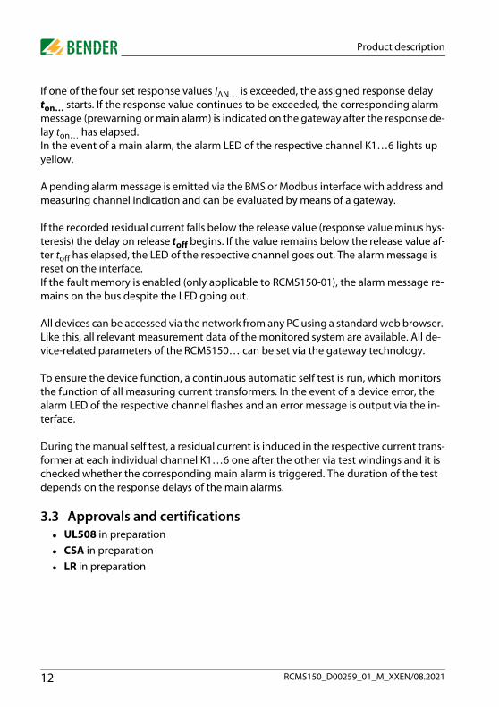
6.3 Measured values
Register Property Description Format Comment/unit
01000 RO Residual current measured value (K1 RMS) Float32
Current instantaneous value. For status, refer to Tab. 6.3
01002 RO Residual current measured value (K1 DC) Float32
01004 RO Status K1 UINT32
01006 RO Residual current measured value (K2 RMS) Float32
01008 RO Residual current measured value (K2 DC) Float32
01010 RO Status K2 UINT32
01012 RO Residual current measured value (K3 RMS) Float32
01014 RO Residual current measured value (K3 DC) Float32
01016 RO Status K3 UINT32
01018 RO Residual current measured value (K4 RMS) Float32
01020 RO Residual current measured value (K4 DC) Float32
01022 RO Status K4 UINT32
01024 RO Residual current measured value (K5 RMS) Float32
01026 RO Residual current measured value (K5 DC) Float32
01028 RO Status K5 UINT32
01030 RO Residual current measured value (K6 RMS) Float32
01032 RO Residual current measured value (K6 DC) Float32
01034 RO Status K6 UINT32
01036 RODevice error and status information
Float32
If device errors are present, the error code is output here with a factor of 100, see Tab. 6.4.If there are several errors, the error with the highest error number is out-put.Example: 800 = 8.00 (hardware error)
27RCMS150_D00259_01_M_XXEN/08.2021
Overview Modbus registers (RCMS150-01 only)
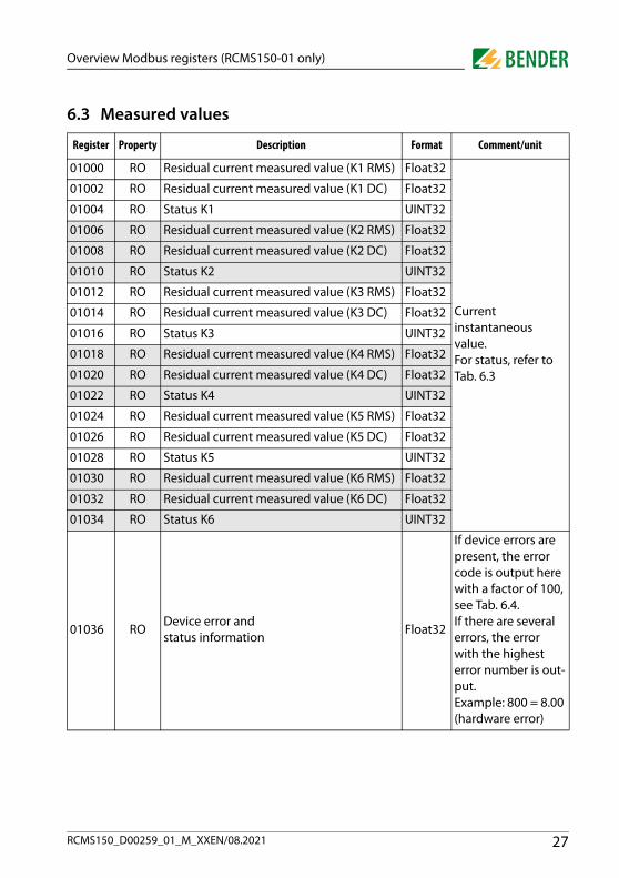
01038 ROResidual current measured value min (K1 RMS)
Float32
Indicates the small-est value since the last readout. In the case of signed measured values, the lowest value is stored temporarily.
01040 ROResidual current measured value min (K1 DC)
Float32
01042 RO Status K1 min UINT32
01044 ROResidual current measured value min (K2 RMS)
Float32
01046 ROResidual current measured value min (K2 DC)
Float32
01048 RO Status K2 min UINT32
01050 ROResidual current measured value min (K3 RMS)
Float32
01052 ROResidual current measured value min (K3 DC)
Float32
01054 RO Status K3 min UINT32
01056 ROResidual current measured value min (K4 RMS)
Float32
01058 ROResidual current measured value min (K4 DC)
Float32
01060 RO Status K4 min UINT32
01062 ROResidual current measured value min (K5 RMS)
Float32
01064 ROResidual current measured value min (K5 DC)
Float32
01066 RO Status K5 min UINT32
01068 ROResidual current measured value min (K6 RMS)
Float32
01070 ROResidual current measured value min (K6 DC)
Float32
01072 RO Status K6 min UINT32
01074 RO Device error and status information min Float32
Register Property Description Format Comment/unit
28 RCMS150_D00259_01_M_XXEN/08.2021

Overview Modbus registers (RCMS150-01 only)
01076 ROResidual current measured value average (K1 RMS)
Float32
Indicates the arith-metic average value since the last read-out.
01078 ROResidual current measured value average (K1 DC)
Float32
01080 Reserved
01082 ROResidual current measured value average (K2 RMS)
Float32
01084 ROResidual current measured value average (K2 DC)
Float32
01086 Reserved
01088 ROResidual current measured value average (K3 RMS)
Float32
01090 ROResidual current measured value average (K3 DC)
Float32
01092 Reserved
01094 ROResidual current measured value average (K4 RMS)
Float32
01096 ROResidual current measured value average (K4 DC)
Float32
01098 Reserved
01100 ROResidual current measured value average (K5 RMS)
Float32
01102 ROResidual current measured value average (K5 DC)
Float32
01104 Reserved
01106 ROResidual current measured value average (K6 RMS)
Float32
01108 ROResidual current measured value average (K6 DC)
Float32
01110Reserved
01112
Register Property Description Format Comment/unit
29RCMS150_D00259_01_M_XXEN/08.2021

Overview Modbus registers (RCMS150-01 only)
Tab. 6.2: Modbus registers: Measured values
01114 ROResidual current measured value max (K1 RMS)
Float32
Indicates the high-est value since the last readout. In the case of signed measured values, the highest value is stored temporarily.
01116 ROResidual current measured value max (K1 DC)
Float32
01118 RO Status K1 max UINT32
01120 ROResidual current measured value max (K2 RMS)
Float32
01122 ROResidual current measured value max (K2 DC)
Float32
01124 RO Status K2 max UINT32
01126 ROResidual current measured value max (K3 RMS)
Float32
01128 ROResidual current measured value max (K3 DC)
Float32
01130 RO Status K3 max UINT32
01132 ROResidual current measured value max (K4 RMS)
Float32
01134 ROResidual current measured value max (K4 DC)
Float32
01136 RO Status K4 max UINT32
01138 ROResidual current measured value max (K5 RMS)
Float32
01140 ROResidual current measured value max (K5 DC)
Float32
01142 RO Status K5 max UINT32
01144 ROResidual current measured value max (K6 RMS)
Float32
01146 ROResidual current measured value max (K6 DC)
Float32
01148 RO Status K6 max UINT32
01150 RO Device error and status information max Float32
01152…31999 Reserved
Register Property Description Format Comment/unit
30 RCMS150_D00259_01_M_XXEN/08.2021

Overview Modbus registers (RCMS150-01 only)
Status K1…6
Tab. 6.3: Status K1…6
Error codes Register 01036
Bit number Description
0 DC prewarning
1 DC main alarm
2 RMS prewarning
3 RMS main alarm
4 Manual self test
5 Device error
6…31 Reserved
Error code
Error Description Action
3.40 Channel error Possible error cause:Temperature too high.
Check if ambient temperature is within the per-missible range. Check if supply voltage DC 24 V is within the permissible range. Check if the resid-ual current through the channel is too high or if there are high pulses.If the above points do not apply and the error occurs frequently, return the device.
6.00Calibration error
Calibration data faulty.Switch the device off and on again. If the error persists, return the device.
6.50Production data faulty
Values outside the limits or checksum incorrect.
Error is only cleared by switching the device off/on. If the error persists, return the device.
7.10 Internal communica-tion error
Device-internal communication is disturbed.
Switch the device off and on again. If the error persists, return the device.7.62
8.46Internal supply voltage
Impermissible deviation If the error occurs frequently, return the device.
31RCMS150_D00259_01_M_XXEN/08.2021

Overview Modbus registers (RCMS150-01 only)
Tab. 6.4: Error codes
6.4 Interface parameters
Tab. 6.5: Interface parameters
* The address is only used if both detent potentiometers are set to 0.
9.10μC parameter error
Parameters outside permissible limits or error while saving. Affected channel:Gateway > Overview measur-ing channels or Modbus regis-ters 1004…1034 (5 = device error)
Switch the device off and on again. Reset the cor-responding channel to factory settings: via the gateway orModbus registers 59013…59018. If the error persists, return the device.
9.60μC parameter error
Parameter outside permissible limits
Switch the device off and on again. Reset device to factory settings: Modbus register 59020. If the error persists, return the device.
9.70μC task/ pro-gramme sequence
General software errorSwitch the device off and on again. If the error persists, return the device.
9.90Error μC cycle generation
Unacceptable deviation or fail-ure of the μC cycle source.
Register Property Description Format Unit Setting range Factory setting
32000 RWModbus address*
UINT16 — 1…247The last two digits of the serial number + 100
32001 RWModbus baud rate
UINT32 Baud
1200 / 2400 / 4800 / 9600 / 19200 / 38400 / 57600
19200
32003 RWModbus parity/stop bit
UINT16 —
0 = 8N21 = 8O12 = 8E13 = 8N14 = 8O25 = 8E2
2 (8E1)
32004…32099 Reserved
Error code
Error Description Action
32 RCMS150_D00259_01_M_XXEN/08.2021

Overview Modbus registers (RCMS150-01 only)
6.5 Parameters
Register Property Description Format Unit Setting range Step sizeFactory setting
32100 Reserved
32102 RW
K1
Response value Hysteresis
Float32 % 10…25 % 0.1 % 15 %
32104 RW toff Float32 s 0 s …10 min 10 ms 1 s
32106 RW t start-up Float32 s 0.5 s…10 min 10 ms 0.5 s
32108 RW Fault memory UINT16 — 0 = off; 1 = on — 0 (off )
32109 Reserved
32110 RW IΔn2 RMS Float32 A 3…300 mA 0.1 mA 30 mA
32112 RW ton main alarm RMS Float32 s 0 s…10 min 10 ms 0 s
32114 RW IΔn1 RMS Float32 % 50…100 % 0.1 % 50 %
32116 RW ton prewarning RMS Float32 s 0 s…10 min 10 ms 1 s
32118 RW IΔn2 DC Float32 A 3…300 mA 0.1 mA 6 mA
32120 RW ton main alarm DC Float32 s 0 s…10 min 10 ms 0 s
32122 RW IΔn1 DC Float32 % 50…100 % 0.1 % 50 %
32124 RW ton prewarning DC Float32 s 0 s…10 min 10 ms 1 s
32126 Reserved
33RCMS150_D00259_01_M_XXEN/08.2021

Overview Modbus registers (RCMS150-01 only)
32128 RW
K2
Response value hysteresis
Float32 % 10…25 % 0.1 % 15 %
32130 RW toff Float32 s 0 s…10 min 10 ms 1 s
32132 RW t start-up Float32 s 0.5 s…10 min 10 ms 0.5 s
32134 RW Fault memory UINT16 — 0 = off; 1 = on — 0 (off )
32135 Reserved
32136 RW IΔn2 RMS Float32 A 3…300 mA 0.1 mA 30 mA
32138 RW ton main alarm RMS Float32 s 0 s…10 min 10 ms 0 s
32140 RW IΔn1 RMS Float32 % 50…100 % 0.1 % 50 %
32142 RW ton prewarning RMS Float32 s 0 s…10 min 10 ms 1 s
32144 RW IΔn2 DC Float32 A 3…300 mA 0.1 mA 6 mA
32146 RW ton main alarm DC Float32 s 0 s…10 min 10 ms 0 s
32148 RW IΔn1 DC Float32 % 50…100 % 0.1 % 50 %
32150 RW ton prewarning DC Float32 s 0 s…10 min 10 ms 1 s
32152 Reserved
32154 RW
K3
Response value hysteresis
Float32 % 10…25 % 0.1 % 15 %
32156 RW toff Float32 s 0 s…10 min 10 ms 1 s
32158 RW t start-up Float32 s 0.5 s…10 min 10 ms 0.5 s
32321 RW Fault memory UINT16 — 0 = off; 1 = on — 0 (off )
32161 Reserved
32162 RW IΔn2 RMS Float32 A 3…300 mA 0.1 mA 30 mA
32164 RW ton main alarm RMS Float32 s 0 s…10 min 10 ms 0 s
32166 RW IΔn1 RMS Float32 % 50…100 % 0.1 % 50 %
32168 RW ton prewarning RMS Float32 s 0 s…10 min 10 ms 1 s
32170 RW IΔn2 DC Float32 A 3…300 mA 0.1 mA 6 mA
32172 RW ton main alarm DC Float32 s 0 s…10 min 10 ms 0 s
32174 RW IΔn1 DC Float32 % 50…100 % 0.1 % 50 %
32176 RW ton prewarning DC Float32 s 0 s…10 min 10 ms 1 s
Register Property Description Format Unit Setting range Step sizeFactory setting
34 RCMS150_D00259_01_M_XXEN/08.2021

Overview Modbus registers (RCMS150-01 only)
32178 Reserved
32180 RW
K4
Response value hys-teresis
Float32 % 10…25 % 0.1 % 15 %
32182 RW toff Float32 s 0 s…10 min 10 ms 1 s
32184 RW t start-up Float32 s 0.5 s…10 min 10 ms 0.5 s
32186 RW Fault memory UINT16 — 0 = off; 1 = on — 0 (off )
32187 Reserved
32188 RW IΔn2 RMS Float32 A 3…300 mA 0.1 mA 30 mA
32190 RW ton main alarm RMS Float32 s 0 s…10 min 10 ms 0 s
32192 RW IΔn1 RMS Float32 % 50…100 % 0.1 % 50 %
32194 RW ton prewarning RMS Float32 s 0 s…10 min 10 ms 1 s
32196 RW IΔn2 DC Float32 A 3…300 mA 0.1 mA 6 mA
32198 RW ton main alarm DC Float32 s 0 s…10 min 10 ms 0 s
32200 RW IΔn1 DC Float32 % 50…100 % 0.1 % 50 %
32202 RW ton prewarning DC Float32 s 0 s…10 min 10 ms 1 s
32204 Reserved
Register Property Description Format Unit Setting range Step sizeFactory setting
35RCMS150_D00259_01_M_XXEN/08.2021

Overview Modbus registers (RCMS150-01 only)
32206 RW
K5
Response value hys-teresis
Float32 % 10…25 % 0.1 % 15 %
32208 RW toff Float32 s 0 s…10 min 10 ms 1 s
32210 RW t start-up Float32 s 0.5 s…10 min 10 ms 0.5 s
32212 RW Fault memory UINT16 — 0 = off; 1 = on — 0 (off )
32213 Reserved
32214 RW IΔn2 RMS Float32 A 3…300 mA 0.1 mA 30 mA
32216 RW ton main alarm RMS Float32 s 0 s…10 min 10 ms 0 s
32218 RW IΔn1 RMS Float32 % 50…100 % 0.1 % 50 %
32220 RW ton prewarning RMS Float32 s 0 s…10 min 10 ms 1 s
32222 RW IΔn2 DC Float32 A 3…300 mA 0.1 mA 6 mA
32224 RW ton main alarm DC Float32 s 0 s…10 min 10 ms 0 s
32226 RW IΔn1 DC Float32 % 50…100 % 0.1 % 50 %
32228 RW ton prewarning DC Float32 s 0 s…10 min 10 ms 1 s
32230 Reserved
32232 RW
K6
Response value hys-teresis
Float32 % 10…25 % 0.1 % 15 %
32234 RW toff Float32 s 0 s…10 min 10 ms 1 s
32236 RW t start-up Float32 s 0.5 s…10 min 10 ms 0.5 s
32238 RW Fault memory UINT16 — 0 = off; 1 = on — 0 (off )
32239 Reserved
32240 RW IΔn2 RMS Float32 A 3…300 mA 0.1 mA 30 mA
32242 RW ton main alarm RMS Float32 s 0 s…10 min 10 ms 0 s
32244 RW IΔn1 RMS Float32 % 50…100 % 0.1 % 50 %
32246 RW ton prewarning RMS Float32 s 0 s…10 min 10 ms 1 s
32248 RW IΔn2 DC Float32 A 3…300 mA 0.1 mA 6 mA
32250 RW ton main alarm DC Float32 s 0 s…10 min 10 ms 0 s
32252 RW IΔn1 DC Float32 % 50…100 % 0.1 % 50 %
32254 RW ton prewarning DC Float32 s 0 s…10 min 10 ms 1 s
Register Property Description Format Unit Setting range Step sizeFactory setting
36 RCMS150_D00259_01_M_XXEN/08.2021
Overview Modbus registers (RCMS150-01 only)
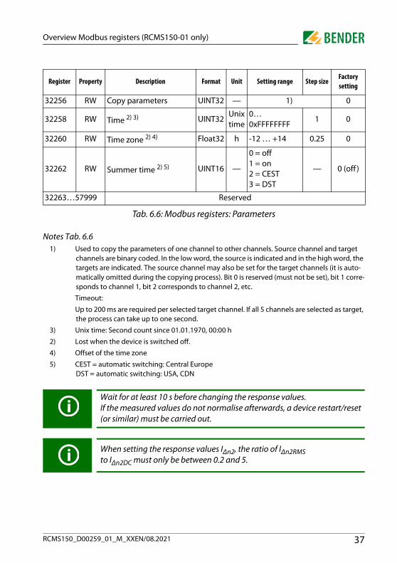
Tab. 6.6: Modbus registers: Parameters
Notes Tab. 6.61) Used to copy the parameters of one channel to other channels. Source channel and target
channels are binary coded. In the low word, the source is indicated and in the high word, the targets are indicated. The source channel may also be set for the target channels (it is auto-matically omitted during the copying process). Bit 0 is reserved (must not be set), bit 1 corre-sponds to channel 1, bit 2 corresponds to channel 2, etc.
Timeout:
Up to 200 ms are required per selected target channel. If all 5 channels are selected as target, the process can take up to one second.
3) Unix time: Second count since 01.01.1970, 00:00 h
2) Lost when the device is switched off.
4) Offset of the time zone
5) CEST = automatic switching: Central Europe DST = automatic switching: USA, CDN
32256 RW Copy parameters UINT32 — 1) 0
32258 RW Time 2) 3) UINT32Unix time
0…0xFFFFFFFF
1 0
32260 RW Time zone 2) 4) Float32 h -12 … +14 0.25 0
32262 RW Summer time 2) 5) UINT16 —
0 = off1 = on2 = CEST 3 = DST
— 0 (off )
32263…57999 Reserved
Wait for at least 10 s before changing the response values.If the measured values do not normalise afterwards, a device restart/reset(or similar) must be carried out.
When setting the response values IΔn2, the ratio of IΔn2RMS to IΔn2DC must only be between 0.2 and 5.
Register Property Description Format Unit Setting range Step sizeFactory setting
37RCMS150_D00259_01_M_XXEN/08.2021

Overview Modbus registers (RCMS150-01 only)
6.6 Control commands
Register Property Description Format Setting rangeFactory setting
Comment
59000 RWAllow register write access
UINT160 = Deny1 = Allow
0 1)
59001 RW K1
Test
UINT16 Read0 = No test per-formed yet1 = Test running2 = Test successful3 = Test failedWrite1 = Start test
0 2)
59002 RW K2 UINT1659003 RW K3 UINT1659004 RW K4 UINT1659005 RW K5 UINT16
59006 RW K6 UINT16
59007 WO K1
Fault mem-ory reset
UINT16
1 = Perform reset
—
3)
59008 WO K2 UINT16 —59009 WO K3 UINT16 —59010 WO K4 UINT16 —59011 WO K5 UINT16 —59012 WO K6 UINT16 —59013 WO K1
Load factory settings
UINT16
1 = Apply factory set-tings
—
4)
59014 WO K2 UINT16 —59015 WO K3 UINT16 —59016 WO K4 UINT16 —59017 WO K5 UINT16 —59018 WO K6 UINT16 —
59019 WO
Load channel-inde-pendent factory settings (without interface)
UINT161 = Apply factory set-tings
— 5)
59020 WO
Load channel-inde-pendent factory settings (with inter-face)
UINT161 = Apply factory set-tings
— 6)
59021 RW Device signalling UINT160 = off1 = on
0 7)
59022 RW Test alarm UINT16 0…12 0 8)
38 RCMS150_D00259_01_M_XXEN/08.2021

Overview Modbus registers (RCMS150-01 only)
Tab. 6.7: Modbus registers: Control commandsNotes Tab. 6.7
1) Flag to allow modification of important registers. Is automatically deactivated after five sec-onds.
2) Manual test on corresponding channel. The duration of the test depends on the set response times.
3) Reset the fault memory on the corresponding channel.
4) Loads all factory settings of the corresponding channel (e.g. parameters of channel 1: regis-ters 32100 to 32124). Secured via register 59000.
5) Loads the following channel-independent factory settings without interface parameters:– Register 1269: Installation location– Register 16162: Time– Register 16164: Time zone– Register 16166: Summer time– Secured via register 59000.
6) Loads the following channel-independent factory settings with interface parameters (secured via register 59000)– Register 1269: Installation location– Register 16158: Modbus address– Register 16159: Modbus baud rate– Register 16161: Modbus parity/stop bit– Register 16162: Time– Register 16164: Time zone– Register 16166: Summer time
7) The Power on LED flashes green quickly to identify the device more quickly in a cluster of devices. Is automatically deactivated after one minute.
8) Output a test alarm on a measuring channel. The test alarm is deactivated after 1 minute (= 0).0 no test alarm/end test alarm1…12 Output test alarm on corresponding channel/active
9) Perform an offset measurement on the corresponding channel. Secured via register 59000.
59023 WO K1
Offset meas-urement
UINT16
1 = Perform offset measurement
—
9)
59024 WO K2 UINT16 —59025 WO K3 UINT16 —59026 WO K4 UINT16 —59027 WO K5 UINT16 —59028 WO K6 UINT16 —59029…59999 Reserved
Register Property Description Format Setting rangeFactory setting
Comment
39RCMS150_D00259_01_M_XXEN/08.2021
Glossary
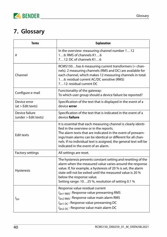
7. Glossary
Terms Explanation
#In the overview: measuring channel number 1…121…6: RMS of channels K1…67…12: DC of channels K1…6
Channel
RCMS150…has 6 measuring current transformers (= chan-nels). 2 measuring channels (RMS and DC) are available for each channel, which makes 12 measuring channels in total:1…6: residual current AC/DC sensitive (RMS)7…12: residual current DC
Configure e-mailFunctionality of the gateway: To which user group should a device failure be reported?
Device error (at > Edit texts)
Specification of the text that is displayed in the event of a device error
Device failure (under > Edit texts)
Specification of the text that is indicated in the event of a device failure
Edit texts
It is essential that each measuring channel is clearly identi-fied in the overview or in the reports. The alarm texts that are indicated in the event of prewarn-ings/main alarms can be identical or different for all chan-nels. If no individual text is assigned, the general text will be indicated in the event of an alarm.
Factory settings All settings are reset.
Hysteresis
The hysteresis prevents constant setting and resetting of the alarm when the measured value varies around the response value. If, for example, a hysteresis of 20 % is set, the alarm state will not be exited until the measured value is 20 % below the response value.Setting range: 10…25 %, resolution of setting 0.1 %
IΔn
Response value residual current IΔn1 RMS : Response value prewarning RMSIΔn2 RMS : Response value main alarm RMSIΔn1 DC : Response value prewarning DCIΔn2 DC : Response value main alarm DC
40 RCMS150_D00259_01_M_XXEN/08.2021

Glossary
Main alarm
In the event of a main alarm, a message is sent via the bus and the respective LED lights up on the RCMS. Is triggered by: Exceeding the set response value during residual cur-
rent measurement Fault of measuring current transformer Device error
Message2 message levels are distinguished: prewarning and main alarm.
OverviewThe current state and the measured value are indicated for all 12 measuring channels (#)
Prewarning
Preliminary stage to main alarm, the less severe response value has been reached (e.g. 50 % of the main alarm response value). If there is a prewarning, a message is sent via the bus. Is triggered by: Exceeding the set response value during residual cur-
rent measurement Fault of measuring current transformer Device error
Report
The report includes: - The current measured values for each channel- Values of the general settings Hysteresis, toff, tstart-up - Response values and ton for prewarnings and main alarms - Information regarding the RCMS150…
Response value main alarm
Response value of the main alarm (IΔn2)
Response value prewarning
Indication of the response value alarm (50…100 %) (IΔn1) as a percentage value
RMSRoot Mean Square: The currents are detected and evaluated as RMS values in the frequency range of 0…2000 Hz.
Terms Explanation
41RCMS150_D00259_01_M_XXEN/08.2021

Glossary
t(off )
Delay on release toffStarts when the condition that triggers the message (for pre-warning or main alarm) no longer exists. The RCMS150… only stops signalling if the condition that triggers the mes-sage no longer exists after the delay on release has elapsed.Setting range: 0…10 minutes.
t(on)
Response delay tonStarts when a condition that triggers the message (for pre-warning and main alarm) exists. Signalling is only done by the RCMS150… if the condition that triggers the message still exists after the response delay has elapsed.Setting range: 0…10 minutes.
t(start-up)
Start-up delay tstart-upTime delay after the RCMS150 has been switched on. No alarm message is generated during this time period. This time delay is required if the RCMS150… and the system to be monitored are switched on simultaneously. Currents caused by switching operations are ignored.Setting range: 500 ms…10 minutes.
Terms Explanation
42 RCMS150_D00259_01_M_XXEN/08.2021
Technical data
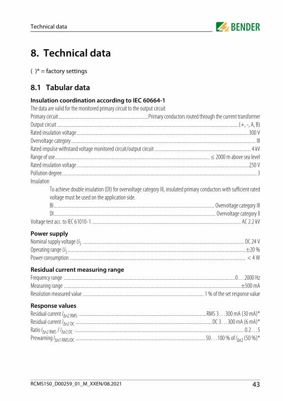
8. Technical data
( )* = factory settings
8.1 Tabular data
Insulation coordination according to IEC 60664-1The data are valid for the monitored primary circuit to the output circuitPrimary circuit ..............................................................................Primary conductors routed through the current transformerOutput circuit ..............................................................................................................................................................(+, -, A, B)Rated insulation voltage......................................................................................................................................................300 VOvervoltage category................................................................................................................................................................. IIIRated impulse withstand voltage monitored circuit/output circuit .................................................................................... 4 kVRange of use....................................................................................................................................... ≤ 2000 m above sea levelRated insulation voltage......................................................................................................................................................250 VPollution degree.......................................................................................................................................................................... 3Insulation
To achieve double insulation (DI) for overvoltage category III, insulated primary conductors with sufficient ratedvoltage must be used on the application side.BI ............................................................................................................................................ Overvoltage category IIIDI............................................................................................................................................. Overvoltage category II
Voltage test acc. to IEC 61010-1 .................................................................................................................................. AC 2.2 kV
Power supplyNominal supply voltage US ............................................................................................................................................. DC 24 VOperating range US ........................................................................................................................................................... ±20 %Power consumption ......................................................................................................................................................... < 4 W
Residual current measuring rangeFrequency range .....................................................................................................................................................0…2000 HzMeasuring range ..........................................................................................................................................................±500 mAResolution measured value .......................................................................................................... 1 % of the set response value
Response valuesResidual current IΔn2 RMS ...............................................................................................................RMS 3…300 mA (30 mA)*Residual current IΔn2 DC .......................................................................................................................DC 3…300 mA (6 mA)*Ratio IΔn2 RMS / IΔn2 DC .................................................................................................................................................... 0.2…5Prewarning IΔn1 RMS/DC ................................................................................................................. 50…100 % of IΔn2 (50 %)*
43RCMS150_D00259_01_M_XXEN/08.2021

Technical data
Response tolerance IΔn1/2DC, 10…500 Hz ....................................................................................................................................... -20…0 %500 Hz…2 kHz ................................................................................................................................ -20…+100 %
Hysteresis ....................................................................................................................................................10…25 % (15 %)*
Time responseStart-up delay tstart-up ................................................................................................................................. 0.5…600 s (0.5 s)*Response delay
ton1 RMS/DC ........................................................................................................................................ 0…600 s (1 s)*ton2 RMS/DC ........................................................................................................................................ 0…600 s (0 s)*
Delay on releasetoff ..................................................................................................................................................... 0…600 s (1 s)*
Indication (LEDs)For a description of the LEDs, refer to page 16ON ........................................................................................................................................................................................ green ALARM K1…K6.................................................................................................................................................................yellow
InterfaceInterface ............................................................................................................................................................................ RS-485Connection.............................................................................................................................................................. terminals A/BCable shielded, shield on one side to PE
recommended..................................................................................................................... CAT6/CAT7 min. AWG23alternative .................................................................................................................................. J-Y(St)Y min. 2 x 0.8
Bus terminating resistor external .............................................................................................................. (2 x) 120 Ω (0.25 W)Protocol.................................................................................................................................................................................. BMS
Cable length ............................................................................................................................................... ≤ 1200 mDevice address ......................................................................................................................................... 2…90 (2)*
Protocol.....................................................................................................................................................................Modbus RTUCable length ............................................................................................................................................... ≤ 1200 mDevice address .........................................................................1…247 (last 2 digits of the serial number + 100)*
Environment/EMCEMC
Immunity ................................................................................................................................................. IEC 62020-1Emission .................................................................................................................................................. IEC 62020-1
Operating temperature......................................................................................................................................... -25…+70 °CClassification of climatic conditions acc. to IEC 60721
Stationary use (IEC 60721-3-3) ......................................................................................................................... 3K23Transport (IEC 60721-3-2) .................................................................................................................................. 2K11Long-term storage (IEC 60721-3-1)................................................................................................................... 1K22
44 RCMS150_D00259_01_M_XXEN/08.2021

Technical data
Classification of mechanical conditions acc. to IEC 60721Stationary use (IEC 60721-3-3)..........................................................................................................................3M11Transport (IEC 60721-3-2) ...................................................................................................................................2M4Long-term storage (IEC 60721-3-1) .................................................................................................................1M12
ConnectionConnection type ......................................................................................................................dual plug-in push-wire terminalConnection properties
rigid/flexible/conductor sizes ................................................................................. 0.2…1.5 mm² / AWG 24…16Multi-conductor connection (2 conductors with the same cross section)
rigid ............................................................................................................................................0.2…1.5 mm²flexible ........................................................................................................................................0.2…1.5 mm²flexible with ferrule without plastic sleeve .............................................................................0.25…1.5 mm²flexible with ferrule with plastic sleeve..................................................................................0.25…0.75 mm²
Stripping length ................................................................................................................................................................ 10 mm
OtherOperating mode ........................................................................................................................................ continuous operationPosition of normal use ........................................................................................................................................................... anyEnclosure material ................................................................................................................................................polycarbonateFlammability class ........................................................................................................................................................ UL94 V-0Screw mounting to standard distribution panels with 12 TE........................................................................................... 2 x M6DIN rail mounting ............................................................................................................................ mounting clip (accessories)Tightening torque ............................................................................................................................................................. 1.5 NmWeight..................................................................................................................................................................................170 g
Measuring current transformerDiameter cable gland ....................................................................................................................................................... 10 mmLoad current ..........................................................................................................................................................................32 A
Bus parametersAlarm............................................................................................................................. threshold value exceeded, system faultMeasured value............................................................................ measured value, DC component, r.m.s. (resolution 0.1 mA)Times ............................................................................................................... response delay, delay on release, start-up delay( )* = Factory settings
45RCMS150_D00259_01_M_XXEN/08.2021

Technical data
8.2 Factory settings of the Modbus interface For an overview of the factory-set parameters, see table 6.6.
8.3 Standards, approvals, certifications
UL508 in preparation CSA in preparationLR in preparation
8.4 Ordering information
Suitable system componentsThe use of the listed power supply units is recommended. The use of a surge protection device is mandatory for these power supply units.
Type Supply voltage US Protocol Art. No.
RCMS150DC 24 V
BMS B94053025
RCMS150-01 Modbus RTU B94053026
Mounting clip for DIN rail mounting B91080110
Description Type Art. No.
Power supply
STEP-PS/1 AC/24 DC/0.5 B94053110
STEP-PS/1 AC/24 DC/1.75 B94053111
STEP-PS/1 AC/24 DC/4.2 B94053112
B94053025 only
46 RCMS150_D00259_01_M_XXEN/08.2021

Technical data
Accessories
* Suitable for measured value and alarm indication only, not suitable for parameter setting
8.5 Document revision history
DescriptionRCMS150
RCMS150-01
Type Art. No.
Condition monitor with inte-grated gateway
X X COM465IP B95061065
X XCP907-I (flush-mounted enclosure)
B95061031
X XCP907-I (control cabinet door mounting)
B95061032
RS-485 repeater X X DI-1DL B95012047
Residual current monitoring system (In this case, no condi-tion monitor/gateway is neces-sary)*
X — RCMS460-D-1 B94053001
X — RCMS460-D-2 B94053002
X — RCMS490-D-1 B94053005
X — RCMS490-D-2 B94053006
Date Document version State/Changes
08/2016 00 First edition
07/2021 01Added Device variant RCMS150-01 with Modbus RTU interfaceUKCA logo
47RCMS150_D00259_01_M_XXEN/08.2021

Technical data
48 RCMS150_D00259_01_M_XXEN/08.2021
INDEX
AAddress setting 18Approvals and certifications 12, 46
CCommissioning 13, 18
DDevice features 11Dimension diagram 14Display elements 15Disposal 8
EError codes 31
FFunctional description 11
GGlossary 40
HHow to use this manual 5
IInstallation, preliminary considerations 13Intended use 9, 10
LLED 31
MMenu overview 21Menu overview RCMS150 21Menu overview RCMS150-01 22Menu structure of the web user interface 43Modbus registers
- Control commands 38- Device information 26- Interface parameters 32- Parameters 33
Mounting 13Mounting the device 13
OOn-site service 6Operating elements 15Ordering information 46
PPeriodic verification 11Product description 11
QQualified personnel 9, 13Quick reference guide 11
RReadout of the info list 43Repair service 6
49RCMS150_D00259_01_M_XXEN/08.2021
INDEX
SScope of delivery 11Screw mounting 14Service 6Standards 46Start page, web user interface 43Starting the web browser 20Support 6System design 20
TTechnical data 43Technical support 6Terminal details 17Training courses 7
WWeb user interface 43Wiring diagram 16Work activities on electrical installations 9Workshops 7
50 RCMS150_D00259_01_M_XXEN/08.2021


Alle Rechte vorbehalten.Nachdruck und Vervielfältigungnur mit Genehmigung des Herausgebers.Änderungen vorbehalten!
Bender GmbH & Co. KGPostfach 1161 • 35301 Grünberg • DeutschlandLondorfer Str. 65 • 35305 Grünberg • DeutschlandTel.: +49 6401 807-0 • Fax: +49 6401 807-259E-Mail: [email protected] • www.bender.de
Fotos: Bender Archiv
All rights reserved.Reprinting and duplicating
only with permission of the publisher.Subject to change!
Bender GmbH & Co. KGPO Box 1161 • 35301 Grünberg • Germany
Londorfer Str. 65 • 35305 Grünberg • GermanyTel.: +49 6401 807-0 • Fax: +49 6401 807-259
E-Mail: [email protected] • www.bender.de
Photos: Bender Archive