Linear RE-1 Telephone Entry - Nortek Security & Control DESCRIPTION Linear’s RE-1 Telephone Entry...
32
RE-1 Residential Telephone Entry System With Built-in Wireless Receiver (760) 438-7000 USA & Canada (800) 421-1587 & (800) 392-0123 Toll Free FAX (800) 468-1340 www.linearcorp.com Installation, Programming, and Operation Instructions
-
Upload
trinhkhanh -
Category
Documents
-
view
217 -
download
0
Transcript of Linear RE-1 Telephone Entry - Nortek Security & Control DESCRIPTION Linear’s RE-1 Telephone Entry...

RE-1Residential Telephone Entry System
With Built-in Wireless Receiver
(760) 438-7000USA & Canada (800) 421-1587 & (800) 392-0123
Toll Free FAX (800) 468-1340www.linearcorp.com
Installation,Programming,and Operation Instructions
PRINTER’S INSTRUCTIONS:INSTR,INSTL,RE-1 - LINEAR P/N: 217490 C - INK: BLACK - MATERIAL: 20 LB. MEAD BOND WITH 80 LB. WHITE COATED COVER - SIZE: 8.500” X 11.000” - SCALE: 1-1 - FOLDING: ALBUM-FOLD - BINDING: SADDLE-STITCH

CONTENTS FEATURES• TWO-WAY SPEAKERPHONE• CALL WAITING• CALL FORWARDING• DISTINCTIVE RINGS FOR ACCESS CALLS• SEVEN ACCESS TIME ZONES• TIMED “DO NOT DISTURB” PRIVACY FEATURE• DIGITALLY SYNTHESIZED HUMAN VOICE PROMPTS• RESIDENCE CONTROL OF RELAYS• PROGRAMMABLE RELAY CONTROL PREFIXES• 100 ENTRY CODE CAPACITY• 1-6 DIGIT ENTRY CODE LENGTH• EACH ENTRY CODE CAN BE PROGRAMMED TO
ACTIVATE EITHER OR BOTH RELAYS• 100 TRANSMITTER CAPACITY• SUPPORTS 24 BLOCKS OF TRANSMITTERS• SUPPORTS MGT SAFETY EDGE TRANSMITTER • INTERNAL CLOCK AND CALENDAR WITH BATTERY
BACKUP• EVENT LOG MEMORY RETAINS THE LAST 450
SYSTEM EVENTS• KEYPAD PROGRAMMABLE• LOCALLY & REMOTELY PROGRAMMABLE WITH A
TELEPHONE OR COMPUTER• PROGRAMMING SOFTWARE BUILT-IN, CONNECT
WITH ANY INTERNET BROWSER• WEATHER-PROOF, TAMPER-RESISTANT HOUSING• SUPERHETERODYNE RADIO RECEIVER• INTEGRAL RADIO ANTENNA• REMOTE KEYPAD SUPPORT• BRIGHT WHITE LED DOWNLIGHT• PIEZO SOUNDER• 2 HEAVY DUTY FORM “C” (N.O. & N.C) RELAY
OUTPUTS• TIMED ANTI-PASSBACK• KEYPAD LOCKOUT• TACTILE KEY FEEL• TWO DOOR SENSE/INHIBIT INPUTS• TWO OPEN REQUEST INPUTS• ACCESS KEYSWITCH PROVISION• REMOVABLE TERMINAL BLOCKS• OPTIONAL CCTV CAMERA WITH INFRARED
ILLUMINATORS
PRODUCT DESCRIPTION . . . . . . . . . . . . . . . . . . . . . . . . . .1
INSTALLATION INFORMATION . . . . . . . . . . . . . . . . . . . . 2
COMPONENT LOCATIONS . . . . . . . . . . . . . . . . . . . . . . . . 3
WIRING DIAGRAM . . . . . . . . . . . . . . . . . . . . . . . . . . . . . . 4
ENTRY SYSTEM MOUNTING . . . . . . . . . . . . . . . . . . . . . . 5
TELEPHONE WIRING . . . . . . . . . . . . . . . . . . . . . . . . . . . 5
TELEPHONE WIRING OPTIONS . . . . . . . . . . . . . . . . . . . . 6
MULTIPLE UNIT INSTALLATIONS . . . . . . . . . . . . . . . . . . 7
CONTROL WIRING. . . . . . . . . . . . . . . . . . . . . . . . . . . . . . 8
POWER, BATTERY, & GROUND WIRING . . . . . . . . . . . . . . 9
OPTIONAL REMOTE KEYPAD . . . . . . . . . . . . . . . . . . . . . 9
OPTIONAL KEYSWITCH . . . . . . . . . . . . . . . . . . . . . . . . .10
OPTIONAL CCTV CAMERA . . . . . . . . . . . . . . . . . . . . . . . 11
PROGRAMMING ACCESS . . . . . . . . . . . . . . . . . . . . . . . . .12
LOCAL PROGRAMMING ACCESS . . . . . . . . . . . . . . . . . . .18
REMOTE PROGRAMMING ACCESS . . . . . . . . . . . . . . . . .18
PROGRAMMING REFERENCE . . . . . . . . . . . . . . . . . . . . .19
BASIC SYSTEM PROGRAMMING . . . . . . . . . . . . . . . . . . 20
ENTRY CODE PROGRAMMING . . . . . . . . . . . . . . . . . . . . 20
TRANSMITTER PROGRAMMING . . . . . . . . . . . . . . . . . . .21
TELEPHONE PROGRAMMING . . . . . . . . . . . . . . . . . . . . .21
ADVANCED SYSTEM PROGRAMMING . . . . . . . . . . . . . . 22
SYSTEM ADJUSTMENTS . . . . . . . . . . . . . . . . . . . . . . . 24
RE-1 OPERATION . . . . . . . . . . . . . . . . . . . . . . . . . . . . . 25
RESIDENT PROGRAMMING QUICK REFERENCE . . . . . . 26
SPECIFICATIONS . . . . . . . . . . . . . . . . . . . . . . . . . . . . . 27
DIMENSION DRAWING . . . . . . . . . . . . . . . . . . . . . . . . . 27
TROUBLESHOOTING . . . . . . . . . . . . . . . . . . . . . . . . . . . 27
PROGRAMMING WORKSHEET . . . . . . . . . . . . . . . . . . . . 28
LINEAR LIMITED WARRANTY . . . . . . . . . . . . . . . . . . . . 30

1
PRODUCT DESCRIPTIONLinear’s RE-1 Telephone Entry System is designed for residential or light commercial access control applications. The speakerphone, keypad, radio receiver, and optional video camera are housed in a rugged enclosure that can be mounted to a pedestal or bolted directly to a wall. The die-cast keypad keys have bright, easy-to-read graphics and are lit with an overhead light. The two operation buttons; CALL and HELP, are machined for heavy-duty reliability.
OperationArriving visitors will approach the unit and place a call to the residence by pressing the CALL button. The RE-1 will acquire the residence’s local telephone line and generate distinctive rings to the house telephones. The resident, knowing that the distinctive ring is originating from the access area, can answer any house telephone and converse with the visitor. If the resident decides to grant access to the visitor, they can activate either output relay in the RE-1 by pressing a key on the telephone’s keypad. If the resident decides not to grant access, hanging up or pressing a key will disconnect the visitor’s call.Call WaitingIf the resident is using the telephone at the time a visitor calls, the RE-1 will sound beeps on the telephone line to announce that a visitor is calling. The resident can press a key on the telephone to place the outside caller on hold and communicate with the visitor. After granting or denying access to the visitor, the outside caller will be re-connected to the resident.Call ForwardingProgrammable call forwarding allows the RE-1 to dial any selected telephone number when a visitor presses the CALL button. For example, with call forwarding enabled, the RE-1 could dial a cell phone to contact the resident while outside or away from the residence. The resident will be able to communicate with the visitor and grant or deny access from the remote telephone. Alternate NumbersFor installations where multiple residences exist inside the same controlled opening (such as a guest house or granny fl at) three alternate calling numbers can be programmed. The alternate numbers can be called by entering a short code at the keypad.Local ControlThe resident can issue control commands from the local telephones without a call from a visitor. By dialing a specifi c series of digits, the resident can control either of the two relays. The resident can also initiate voice communications with the entry system.
Access MediaUp to 100 entry codes, from 1 to 6 digits in length, can be programmed. Each entry code can activate either, or both, of the relay outputs. Linear’s Model AM-KP keypad can be used as a secondary remote keypad for the RE-1.Up to 24 sets of block coded MegaCode® transmitters (up to 100 transmitters total) can be used to gain access through the RE-1’s built-in radio receiver. Each transmitter can be individually suspended or re-activated. One facility code can be programmed to identify each block of transmitters. Programming of individual (non-block coded) transmitters is not supported by the RE-1.
System FeaturesTime ZonesThe RE-1 contains an internal clock and calendar. Seven programmable “time zones” allow setting time periods to schedule system functions. Each time zone can be active or inactive on certain days. Keypad entry codes, wireless transmitters, automatic access control, call forwarding, and the “Do Not Disturb” feature can each be set to only be active during a specifi c time zone period. Up to ten “holiday” days can be programmed. Each of the seven time zones can be set to be active or inactive during a holiday.Portal SupervisionThe SENSE/INHIBIT input can be used two ways. If programmed for “door sense”, a switch on the door detects forced entry or door ajar situations. If programmed for “inhibit”, the input can be wired to a “service” switch or automatic timer that will disable the Relay #1 when required.Hardwired ActivationThe OPEN REQUEST input can be wired to an exit loop detector or exit photo beam to allow automatic exit activation. An emergency access keyswitch can be mounted in the RE-1 case to allow keyed entry for authorized personnel.Access SecurityThe “anti-passback” feature allows the option of preventing the use of the same code or the same transmitter again before the programmed time elapses. The “keypad lockout” feature discourages tampering by disabling the keypad for one minute after a programmable number of incorrect entry codes has been entered at the keypad.Event LogAn access log of up to 450 events is stored in the unit’s memory. System activity is logged as it occurs with the date and time of the event. The access log data can be retrieved locally or remotely with a computer through the RE-1’s built-in modem.Local & Remote ProgrammingThe system’s built-in programming software can be accessed on-site or off-site using a computer with any Internet browser. The software’s graphic display of each of the programming steps make programming easy. Without a computer, the RE-1 can be programmed with its main keypad, from any local telephone connected to the same line, or by calling from any remote telephone.The EEPROM memory retains all entry codes, transmitter information, and programming, even without power.Obstacle DetectionLinear’s Model MGT safety edge transmitter is compatible with the RE-1 This MGT detects and transmits obstacle events to the RE-1 receiver. Obstacle signals from an MGT transmitter will activate Relay #2. Alarm InterfaceRelay #2 can be programmed for alarm shunt to bypass an alarm loop during entry, or alarm trigger to cause an alarm during forced entry. Four activation options are available for Relay #2.Voice SynthesizerA built-in voice synthesizer sounds voice prompts through the speaker, local and remote telephones.

2
INSTALLATION INFORMATIONBefore beginning installation, please review the entire instructions and become familiar with the system’s operation, wiring, and programmable options.
System LocationFor pedestrian door or gate installations, mount the Entry System on a rigid wall near the controlled door. Avoid mounting the unit in a location where regular mechanical shock will occur due to a slamming door or spring loaded pedestrian gate.For vehicular gate installations, mount the Entry System in clear view of the gate, but far enough from the gate so the user cannot touch the gate from the keypad.
★ WARNING FOR ALL GATE INSTALLATIONS: TO AVOID SERIOUS INJURY OR DEATH, MAKE SURE THAT THE UNIT IS FAR ENOUGH FROM THE GATE SO THAT THE USER CANNOT TOUCH THE GATE WHILE OPERATING THE KEYPAD. HOWEVER, FOR SAFETY, THE GATE MUST BE FULLY VISIBLE FROM THE KEYPAD.
RFI Filter InstallationAn in-line ferrite RFI fi lter has been included with this unit to install during the wiring of the RE-1 Residential Telephone Entry System.✦ NOTE: To insure FCC Part 15 Class B compliance, the following steps
must be performed at the time the RE-1 is installed.1. Open the ferrite RFI fi lter case by gently pulling on the side locking
tab and swinging the case open (see Figure 1).★ CAUTION: The ferrite parts of the RFI fi lter are fragile.
DO NOT DROP THE FILTER ON A HARD SURFACE! Damage to the fi lter may result.
2. After completing the RE-1 installation, route all wires except the AC transformer and telephone lines through the grove in the ferrite core of the RFI fi lter. The fi lter must be installed outside of the RE-1 case. With the wires captured inside, close the ferrite RFI fi lter case and snap it shut (see Figure 1).
✦ NOTE: Be sure the fi lter is located no further than two inches from the rear case cover of the RE-1.
Telephone WiresThe quality of the system’s audio communications is related to the type of telephone wire and its installation. Noise and hum can be introduced into the telephone wires. Use only high-quality telephone wire rated for direct underground burial. All telephone wire should be twisted-pair.• Minimum size of 24 AWG for up to 800 feet.
• Minimum size of 22 AWG for up to 1600 feet.
• Minimum size of 20 AWG for up to 2200 feet.
• Minimum size of 18 AWG for up to 3600 feet.
DO NOT ROUTE TELEPHONE AND AC WIRING INSIDE THE SAME CONDUIT. Route all telephone wires inside a dedicated conduit that is at least six inches away from any AC line wiring.
Power SupplyUse the supplied 16-volt 20-VA transformer to power the RE-1. DO NOT POWER ANY OTHER EQUIPMENT FROM THE SAME TRANSFORMER, use a separate power supply. Keep the system power wires as short as practical to reduce the chance of noise and hum pickup.• For low voltage power wire runs up to 100 feet, use 18 AWG, THHN
600-volt insulated wire.
• For low voltage power wire runs up to 200 feet, use 16 AWG, THHN 600-volt insulated wire.
• Use 22 AWG or larger (depending on the load) for all other connections.
ALWAYS REMOVE POWER PRIOR TO SERVICING
Earth GroundTo avoid damage to the unit from static discharges, connect the RE-1’s EARTH GROUND and case ground terminals to a good earth grounding point within 10 feet. The case ground terminal is the #8 screw located on the backplate above the wire entry hole. Also, the RE-1’s Telephone Bypass Module must be grounded to provide surge protection for the telephone line. Suggested wiring size is 12 AWG for earth ground.
Removable Terminal StripsFor convenience, the RE-1 is provided with removable terminal strips. It is important that these strips be removed evenly in order to avoid causing permanent damage to them.1. Be certain power is off before removing or installing these strips.
2. With a small screwdriver, gently slide the blade between the terminal strip and protective label.
3. Slightly pry fi rst one end, then the other, and then the middle. Repeat the process until the terminal strip can be removed straight off the circuit board by hand. Be very careful to not damage circuit board traces.
4. When re-installing the terminal strips, press down straight and evenly.
Do not remove or install one end fi rst. This will bend pins on the circuit board, which will damage the terminal strip internally. This damage is permanent and can not be repaired by simply straightening the pins on the circuit board.✦ NOTE: Unscrew the terminal screws several turns before inserting
wires.
PULL ON PLASTIC TABTO UNLOCK FILTER CASE
SWING FILTERCASE OPEN
FERRITECORE
RFI FILTERINSTALLEDWITHIN 2"OF RE-1 CASE
PHONE ANDTRANSFORMER WIRESOUTSIDE OF FILTER
NOTE: INSTALLATION OF THE RFI FILTER WILLINSURE MAXIMUM RADIO RECEPTION RANGEFOR ACCESS TRANSMITTERS
Figure 1. RFI Filter Installation

3
12 RELAY TERMINAL BLOCKFor Relay #1 and Relay #2 output connections to the access control devices.
13 RELAY INDICATORSIndicators for Relay #1 and Relay #2 will light when the relay is activated.
14 ANTENNA TERMINAL BLOCKFor shield and center conductor connection of the coax cable from the system’s built-in radio antenna.
15 LINE MONITOR JUMPERFor testing and troubleshooting. Remove jumper to listen to telephone line audio through the speaker.
16 DIGITAL SPEECH VOLUME CONTROLControls the audio level of the voice synthesizer. This adjustment effects the audio level of the voice synthesizer and system tone from the speaker.
17 STATUS INDICATORSSix indicators light to display system power, radio, and modem status.
18 VIDEO CONNECTORFor cable connection to a video monitor. (Optional Model RE-BWC CCTV camera required).
19 CAMERA CONNECTORProvides power and video connection for the optional Model RE-BWC CCTV camera.
20 RESTART BUTTONPressing this button restarts the system. This button DOES NOT erase any programming data.
21 TELEPHONE TERMINAL BLOCKFor telephone line and earth ground connections.
COMPONENT LOCATIONS1 KEYPAD
Die-cast metal 12-key keypad with tactile action. For system programming and keying in entry codes.
2 DOWNLIGHTIlluminates keypad and visitor operation buttons. The light can be programmed to operate dusk to dawn and adjusts its time depending on the system’s geographic location.
3 OPTIONAL CCTV CAMERALocation for the optional Model RE-BWC1 CCTV camera. The camera views the keypad area and has infrared lighting for nighttime use.
4 MICROPHONEThe high-sensitivity microphone monitors sound at the keypad area for the entry system’s speakerphone.
5 CALL BUTTONPressing this button causes the system to call the residence telephones with a distinctive ring signal.
6 HELP BUTTONPressing this button causes the system to play the help message to instruct the visitor on system use.
7 SPEAKERWeatherproof speaker for system operation and programming.
8 INTEGRAL ANTENNAHidden antenna receives wireless radio signals from transmitters.
9 OPTIONAL KEYLOCKLocation for mounting access keylock. (MEDECO keylock with stainless steel cover shown).
10 MAIN TERMINAL BLOCKFor power, backup battery, sense inputs, open request inputs, and remote keypad connections.
11 SPEAKERPHONE VOLUME CONTROLControls the audio level produced by the speaker during communications between the visitor and the resident.
CALL
1
2
3
4
5
6
7
8
9
10
11
12
13 14
15
16
20
21
17
1819

4
WIRING DIAGRAM
GATEOPERATOROPEN
16 VAC20 VA
TRANSFORMER
TELCO
OPEN #1
KEYPAD GND
KEYPAD DAT 1
KEYPAD DAT 0
KEYPAD PWR
TRANSFORMER
TRANSFORMER
BATTERY NEGATIVE
BATTERY POSITIVE
SENSE #1
COMMON
KEYPAD CLK
KEYPAD DVAL
OPEN #2
RELAY#1
RE-1TELEPHONE ENTRY
SYSTEM
SENSE #2
TYPICALGATE INSTALLATIONWIRING
GROUNDSTAKE
N.O
.
CO
M
N.C
.
N.O
.
CO
M
N.C
.
RELAY#2
RIN
G
TIP
RIN
G
TIP
EARTH
HOUSE
TIP
RING
TIP
RING
TIP
RING
TIP
RING
TELCO
RE-1TELCO
RE-1HOUSE
HOUSE
TELEPHONEBYPASSMODULE
EARTHGROUND
TO HOUSEPHONES
TO TELCOLINE
TYPICALDOOR INSTALLATIONWIRING
NOTE: DO NOT POWERTHE LOCKING DEVICE FROMTHE RE-1 TRANSFORMER
ELECTRICDOOR STRIKE
MAGNETICDOOR LOCK
ACCESSDEVICEPOWERSUPPLY
NOTE: A MAGNETIC LOCK ANDDOOR STRIKE ARE BOTH SHOWN,TYPICALLY ONLY ONE IS USED
16 VAC20 VA
TRANSFORMER
TELCO
OPEN #1
KEYPAD GND
KEYPAD DAT 1
KEYPAD DAT 0
KEYPAD PWR
TRANSFORMER
TRANSFORMER
BATTERY NEGATIVE
BATTERY POSITIVE
SENSE #1
COMMON
KEYPAD CLK
KEYPAD DVAL
OPEN #2
RELAY#1
RE-1TELEPHONE ENTRY
SYSTEM
SENSE #2
N.O
.
CO
M
N.C
.
N.O
.
CO
M
N.C
.
RELAY#2
RIN
G
TIP
RIN
G
TIP
EARTH
HOUSE
TIP
RING
TIP
RING
TIP
RING
TIP
RING
TELCO
RE-1TELCO
RE-1HOUSE
HOUSE
TELEPHONEBYPASSMODULE
EARTHGROUND
TO HOUSEPHONES
TO TELCOLINE
RELAY RATING:3 AMPS AT
30 VOLTS AC OR DCMAXIMUM
RELAY RATING:3 AMPS AT
30 VOLTS AC OR DCMAXIMUM
10' MAXIMUMWIRE RUN
GROUNDSTAKE
10' MAXIMUMWIRE RUN
GROUNDSTAKE
10' MAXIMUMWIRE RUN
GROUNDSTAKE
10' MAXIMUMWIRE RUN
CASEGROUND
CASEGROUND

5
ENTRY SYSTEM MOUNTINGPedestal Mounting
The RE-1 Entry System can be mounted on a standard pedestal.1. Open the RE-1 case by removing the two security screws with the
wrench provided (see Figure 2).2. Use four security bolts and locking nuts to secure the backplate to the
pedestal (see Figure 3).
Wall MountingThe RE-1 Entry System can be mounted directly to a wall or fl at surface.1. Open the RE-1 case by removing the two security screws with the
wrench provided (see Figure 2).2. Use the appropriate fasteners to secure the system’s backplate to the
mounting surface. When mounting the system to a concrete wall, use concrete wedge anchors (see Figure 4).
TELEPHONE WIRINGThe RE-1 connects between the incoming telephone line of the residence and local telephone sets.
Telephone Bypass ModuleThe RE-1’s Telephone Bypass Module provides surge protection and a switch to remove the RE-1 from the telephone line and re-connect the local telephones to the telephone system. ALL TELEPHONE WIRING FOR THE RE-1 MUST PASS THROUGH THE BYPASS MODULE.The bypass module is housed in a weather-resistant enclosure and should be located in an area that is easily accessible to the resident. In case of system trouble, the resident can use the bypass switch to remove the RE-1 from the telephone system.
Telephone Wiring• DO NOT ROUTE TELEPHONE AND AC WIRING INSIDE THE SAME
CONDUIT. Route all telephone wires inside a dedicated conduit that is at least six inches away from any AC line wiring.
• All telephone wiring must be made on the “house” side of the telephone company’s demarcation device (the terminal block where the telephone line connects to the residence).
• If any security system or personal alert system at the residence is connected to the telephone line, be sure that it is connected to the line ahead of the Telephone Bypass Module using a RJ-31X or RJ-38X interface.
• Use only high-quality telephone wire rated for direct underground burial. All telephone wire should be twisted-pair with a minimum size of 24 AWG.
Typical Telephone Wiring1. Connect the bypass module’s EARTH GROUND terminal to a good
earth ground.2. Before connecting the incoming telephone line to the bypass module
check the polarity of the wires with a DC voltmeter. Connect the negative wire (RING - usually green) to the bypass module TELCO RING terminal. Connect the positive wire (TIP - usually red) to the bypass module TELCO TIP terminal.
3. Connect the resident’s local telephone line RING (usually green) to the bypass module HOUSE RING. Connect the local telephone line TIP (usually red) to the bypass module HOUSE TIP terminal.
4. Connect the RE-1 TELCO RING to the bypass module RE-1 TELCO RING terminal. Connect the RE-1 TELCO TIP to the bypass module RE-1 TELCO TIP terminal.
5. Connect the RE-1 HOUSE RING to the bypass module RE-1 HOUSE RING terminal. Connect the RE-1 HOUSE TIP to the bypass module RE-1 HOUSE TIP terminal.
Figure 4. Wall Mounting Backplate
Figure 3. Pedestal Mounting Backplate
REMOVE THE TWOSECURITY SCREWSTO OPEN THE CASE
Figure 2. Opening the RE-1 Case
Figure 5. Telephone Wiring
PEDESTALMOUNTING MOUNT BACKPLATE
WITH SECURITY BOLTSAND LOCKNUTS
PEDESTALCAUTION!BE SURE THE MOUNTING HARDWAREDOES NOT EXTEND MORE THAN 1/2"INSIDE THE BACKPLATE ORELECTRICAL DAMAGE MAY OCCUR
CASE GROUND SCREW
USE WEDGE ANCHORSFOR CONCRETE OROTHER APPROPRIATEANCHORS FOR DIFFERENTMATERIALS
WALLMOUNTING
CAUTION!BE SURE THE MOUNTING HARDWAREDOES NOT EXTEND MORE THAN 1/2"INSIDE THE BACKPLATE ORELECTRICAL DAMAGE MAY OCCUR
GROUNDSTAKE
TIP
RING
TIP
RING
TIP
RING
TIP
RING
TELCO
RE-1TELCO
RE-1HOUSE
HOUSE
TELCO
RING
TIP
RING
TIP
EARTH
HOUSE
TELEPHONEBYPASSMODULE
EARTHGROUND
TO HOUSEPHONES
TO TELCOLINE
RE-1ENTRY
SYSTEM
TELEPHONEBYPASSMODULE
CASE GROUND

6
TELEPHONE WIRING OPTIONSShared Line
This is the standard confi guration. The telephone line is routed through the RE-1 to the house phones. Pressing the Call button on the RE-1 will cause the RE-1 to disconnect the house phones from the telephone company line and generate a ring signal that is heard on the house phones.
Dedicated LinePressing the Call button on the RE-1 will cause the RE-1 to sieze the phone line and dial out to an outside number.
See PPN #54 for programming options.
Intercom ModePressing the Call button on the RE-1 will cause the RE-1 to generate a ring signal as if it were an intercom station. A live phone line is not used and the RE-1 provides power for the remote intercom phone. ✦ NOTE: In this mode, remote programming, call forwarding or alternate
resident calling is not available.
See PPN #52 for programming options.
Ring Down ModePressing the Call button on the RE-1 will cause the RE-1 to sieze the phone line and provide immediate communications with the PBX system.
See PPN #54 for programming options.
TELCO
RIN
G
TIP
RIN
G
TIP
EARTH
HOUSE
TIP
RING
TIP
RING
TIP
RING
TIP
RING
TELCO
RE-1TELCO
RE-1HOUSE
HOUSE
TELEPHONEBYPASSMODULE
EARTHGROUNDFROM
TELEPHONECOMPANY
GROUNDSTAKE
10' MAXIMUMWIRE RUN
GROUNDSTAKE
10' MAXIMUMWIRE RUN
RE-1ENTRY
SYSTEM
CASEGROUND
GROUNDSTAKE
TIP
RING
TIP
RING
TIP
RING
TIP
RING
TELCO
RE-1TELCO
RE-1HOUSE
HOUSE
TELCO
RING
TIP
RING
TIP
EARTH
HOUSE
TELEPHONEBYPASSMODULE
EARTHGROUND
TO HOUSEINTERCOM
TELEPHONES
RE-1ENTRY
SYSTEM
CASEGROUND
GROUNDSTAKE
TIP
RING
TIP
RING
TIP
RING
TIP
RING
TELCO
RE-1TELCO
RE-1HOUSE
HOUSE
TELCO
RING
TIP
RING
TIP
EARTH
HOUSE
TELEPHONEBYPASSMODULE
EARTHGROUND
TO PBX
SYSTEM
RE-1ENTRY
SYSTEM
CASEGROUND
TELCO
RIN
G
TIP
RIN
G
TIP
EARTH
HOUSE
TIP
RING
TIP
RING
TIP
RING
TIP
RING
TELCO
RE-1TELCO
RE-1HOUSE
HOUSE
TELEPHONEBYPASSMODULE
EARTHGROUND
TO HOUSEPHONES
FROMTELEPHONECOMPANY
GROUNDSTAKE
10' MAXIMUMWIRE RUN
GROUNDSTAKE
10' MAXIMUMWIRE RUN
RE-1ENTRY
SYSTEM
CASEGROUND
Figure 7. Dedicated Line Wiring
Figure 6. Shared Line Wiring
Figure 8. Intercom Mode Wiring
Figure 9. Ring Down Mode Wiring

7
MULTIPLE UNIT INSTALLATIONSAny of the four basic operation modes (Shared Line, Dedicated Line, Intercom, and Ring Down) may be used with multiple RE-1s in the same installation. The telephone line wiring is “daisy chained” (the telephone line routes through one unit to the next) as shown below. Always connect the telephone line + to TIP, and - to RING.The Telephone Bypass Module only performs the bypass function in the Shared Line Mode, but it will provide extra electrical surge protection in all modes. A surge on the TELCO terminals will be suppressed through the EARTH GROUND terminal. Always use separate AC transformers to power each RE-1.When multiple units are connected together, only two units can be controlled by resident telephone commands, and only one unit can be programmed to answer the telephone (PPN #33) for remote telephone commands. Remote programming via computer is not supported when using multiple RE-1s.
Command Prefi x for Multiple UnitsProgramming and relay control may be through the individual RE-1 keypads or through the house telephone(s) when using the Shared Line or Intercom Modes. To support using the house telephone(s) to issue commands, each RE-1 must be programmed to a different “command prefi x” (PPN #72).
• Set one unit’s command prefi x to
• Set the other unit’s command prefi x to In the case of simultaneous visitors at different units when using the Shared Line Mode, putting one RE-1 “on hold” to communicate with the second RE-1, then returning to the fi rst RE-1 is not recommended. Instead, fi nish all communications with the fi rst RE-1 before servicing the second RE-1. Simultaneous visitors at multiple units used on a single line wired in the Ring Down Mode will cause a “conference call” effect between units
Figure 10. Multiple Unit Wiring
TIP
RING
TIP
RING
TIP
RING
TIP
RING
TELCO
RE-1TELCO
RE-1HOUSE
HOUSE
TELEPHONEBYPASSMODULE
EARTHGROUND
GROUNDSTAKE
FIRSTRE-1
ENTRY SYSTEM
TELCO
RIN
G
TIP
RIN
G
TIP
EARTH
HOUSE
CASEGROUND
LASTRE-1
ENTRY SYSTEM
TELCO
RIN
G
TIP
RIN
G
TIP
EARTH
HOUSE
CASEGROUND
FROMTELEPHONECOMPANY
TOHOUSE
TELEPHONES
GROUNDSTAKE
GROUNDSTAKE
TIP
RING
TIP
RING
TIP
RING
TIP
RING
TELCO
RE-1TELCO
RE-1HOUSE
HOUSE
TELEPHONEBYPASSMODULE
EARTHGROUND
GROUNDSTAKE
FIRSTRE-1
ENTRY SYSTEM
TELCO
RIN
G
TIP
RIN
G
TIP
EARTH
HOUSE
CASEGROUND
LASTRE-1
ENTRY SYSTEM
TELCO
RIN
G
TIP
RIN
G
TIP
EARTH
HOUSE
CASEGROUND
TOINTERCOM
TELEPHONES
GROUNDSTAKE
GROUNDSTAKE
SHARED LINEMODE
INTERCOMMODE
DEDICATED LINEMODE
RING DOWNMODE
PROGRAM THISRE-1 UNIT ONLY FOR
"INTERCOM MODE"(PPN #52)
DO NOT CONNECTTO A LIVE TELEPHONE LINE
TIP
RING
TIP
RING
TIP
RING
TIP
RING
TELCO
RE-1TELCO
RE-1HOUSE
HOUSE
TELEPHONEBYPASSMODULE
EARTHGROUND
GROUNDSTAKE
FIRSTRE-1
ENTRY SYSTEM
TELCO
RIN
G
TIP
RIN
G
TIP
EARTH
HOUSE
CASEGROUND
LASTRE-1
ENTRY SYSTEM
TELCO
RIN
G
TIP
RIN
G
TIP
EARTH
HOUSE
CASEGROUND
FROMTELEPHONECOMPANY
OR PBX
GROUNDSTAKE
GROUNDSTAKE
PROGRAM ALLRE-1 UNITS FOR
"CALL FORWARDING"(PPN #54)
TIP
RING
TIP
RING
TIP
RING
TIP
RING
TELCO
RE-1TELCO
RE-1HOUSE
HOUSE
TELEPHONEBYPASSMODULE
EARTHGROUND
GROUNDSTAKE
FIRSTRE-1
ENTRY SYSTEM
TELCO
RIN
G
TIP
RIN
G
TIP
EARTH
HOUSE
CASEGROUND
LASTRE-1
ENTRY SYSTEM
TELCO
RIN
G
TIP
RIN
G
TIP
EARTH
HOUSE
CASEGROUND
FROMPBX
GROUNDSTAKE
GROUNDSTAKE
PROGRAM ALLRE-1 UNITS FOR
"RING DOWN MODE"(PPN #54)
IF DESIRED, CHANGERESIDENT RESPONSE KEYS
(PPN #71)

8
CONTROL WIRINGGate Control
1. Route two wires between the gate and the RE-1. Connect the gate operator’s OPEN terminals to the RE-1 Relay #1 COM & N.O. terminals.
✦ NOTE: For operator wiring specifi cs, refer to the gate operator’s wiring diagram.
2. If an access keyswitch is required refer to the Optional Keyswitch section of this manual for details on keyswitch wiring and installation.
3. If an external timer for preventing access at certain times is required, route two wires from the RE-1 to the timer contacts. Connect the timer contacts to the RE-1 SENSE #1 and COMMON terminals.
✦ NOTE: If the sense input is going to be used as an inhibit input, it must be programmed to select that input type. See programming PPN #29.
Door or Pedestrian Gate Control1. Install a low voltage electric door strike or magnetic lock as a locking
device for the door or pedestrian gate.2. Install the power supply or transformer for the locking device. DO NOT
POWER THE RE-1 FROM THIS POWER SUPPLY.3. Connect one wire from the power supply to one wire from the locking
device.4. Route two wires between the locking device and the RE-1. Connect
one wire to the remaining wire of the locking device. Connect the other wire to the remaining wire of the power supply.
• For a door strike, connect the wires to the RE-1 Relay #1 COM & N.O. terminals.
• For a magnetic lock, connect the wires to the RE-1 Relay #1 COM & N.C. terminals.
5. If an access keyswitch is required refer to the Optional Keyswitch section of this manual for details on keyswitch wiring and installation.
6. To use the door sense feature to detect forced entry or door ajar conditions, install a normally closed door switch on the door or pedestrian gate and route two wires from the switch to the RE-1. Connect the door sense switch to the RE-1 SENSE #1 and COMMON terminals. See programming PPN #24 & #27 to defi ne when Relay #2 will activate based on the sense input.
Figure 12. Gate Installation Wiring
Figure 13. Door Installation ExampleFigure 11. Gate Installation Example
Figure 14. Door Installation Wiring
DOORSENSESWITCH
ACCESSKEYSWITCH
OPEN #1
KEYPAD GND
KEYPAD DAT 1
KEYPAD DAT 0
KEYPAD PWR
TRANSFORMER
TRANSFORMER
BATTERY NEGATIVE
BATTERY POSITIVE
SENSE #1
COMMON
KEYPAD CLK
KEYPAD DVAL
OPEN #2
RELAY#1
RE-1TERMINALS
SENSE #2
OPTIONAL WIRING
REQUIRED WIRING
N.O
.
CO
M
N.C
.
N.O
.
CO
M
N.C
.
RELAY#2
ELECTRICDOOR STRIKE
DOOR STRIKEPOWER SUPPLY
2 WIRES FOR DOORSTRIKE POWER FROMPOWER SUPPLY
DOORSENSESWITCH
ELECTRICDOORSTRIKE
RE-1ENTRYSYSTEM
2 WIRESFOR DOORSTRIKE
2 WIRESFOR DOORSENSESWITCH
2 WIRES FOR RE-1POWER FROMTRANSFORMER
4 WIRES FORTELEPHONE
NOTE: ROUTE TELEPHONEWIRES AWAY FROMPOWER WIRESRE-1
ENTRYSYSTEM
2 WIRES FROMTRANSFORMERFOR RE-1 POWER
GATEOPERATOR(BEHIND GATE)
2 WIRES FROM RE-1TO GATE OPEN TERMINALS
4 WIRES FORTELEPHONE
NOTE: ROUTE TELEPHONEWIRES AWAY FROM POWERWIRES
GATEOPERATOROPEN
INHIBITTIMER
ACCESSKEYSWITCH
OPEN #1
KEYPAD GND
KEYPAD DAT 1
KEYPAD DAT 0
KEYPAD PWR
TRANSFORMER
TRANSFORMER
BATTERY NEGATIVE
BATTERY POSITIVE
SENSE #1
COMMON
KEYPAD CLK
KEYPAD DVAL
OPEN #2
RELAY#1
RE-1TERMINALS
SENSE #2
OPTIONAL WIRING
REQUIRED WIRING
NOTE: IN THIS EXAMPLESENSE #1 TERMINAL ISSET AS AN INHIBIT INPUT
N.O
.
CO
M
N.C
.
N.O
.
CO
M
N.C
.
RELAY#2

9
POWER, BATTERY, & GROUND WIRINGPower Wiring
✦ NOTE: DO NOT APPLY POWER UNTIL THE INSTALLATION IS COMPLETE.
1. Route two wires between the RE-1 and the power transformer. • For power wire runs up to 100 feet, use 18 AWG, THHN 600-volt
insulated wire.
• For power wire runs up to 200 feet, use 16 AWG, THHN 600-volt insulated wire.
2. Connect the wires to the transformer. Connect the other end of the wires to the two RE-1 TRANSFORMER terminals.
Backup BatteryUse of battery backup is optional. It will allow the RE-1 to operate for short periods of time without AC power. Two 12-volt backup batteries in series are recommended to obtain the proper working voltage for the RE-1. A single 12-volt battery can be used, although the call waiting beeps and the ring voltage will be lower than normal when fi ve telephones are connected. The door or gate access device must use some type of battery backup for the entire system to be functional.Backup batteries will not fi t into the RE-1 housing. Protect the backup batteries inside a rain-tight NEMA enclosure suitable for the installation.✦ NOTE: Backup batteries are not required to maintain the RE-1 clock/
calendar and programming memory during power outages.1. Route two wires between the RE-1 and the backup batteries.2. Connect two 1.2 Amp/hour (minimum), 12-volt, gel cell batteries in
series (Battery #1 negative to Battery #2 positive).3. Connect the Battery #1 positive to the RE-1 BATTERY POSITIVE
terminal.4. Connect the Battery #2 negative to the RE-1 BATTERY NEGATIVE
terminal.✦ NOTE: The RE-1 does not supply battery charging current. An
external battery charger will be required to maintain the batteries.
Earth GroundFor the best ground, use size 12 gauge solid wire or larger to connect the to an 8-foot copper ground rod. Locate the ground rod next to the Power and Telephone company rods and bond the rods together with a new clamp. Do not disturb the clamps installed by the Power or Telephone Company. Alternately, connect to a cold water pipe for the earth ground.1. Connect the RE-1 EARTH terminal to the earth ground wire.2. Connect the Telephone Bypass Module EARTH GROUND terminal to
the earth ground wire.
OPTIONAL REMOTE KEYPADThe optional Model AM-KP remote keypad can be used with the RE-1 entry system. A typical application for the remote keypad would be to control a second door or gate. Entry codes are the only method of access allowed at a remote keypad. The default system setting will cause the remote keypad to activate Relay #2.1. Mount the AM-KP keypad onto a pedestal or to a wall.2. Route 6-conductor cable from the RE-1 to the AM-KP.• For wire runs up to 300 feet use 24 AWG Belden Type 9931 or
equivalent.
• For wire runs up to 600 feet use 20 AWG Weico Type 9405 or equivalent.
3. Set the DEVICE ADDRESS rotary switch in the AM-KP to match the remote keypad address in the RE-1 (default = 3).
4. Connect the 6-conductor cable as shown in Figure 17.5. Secure and lock the AM-KP to its mounting plate.
SET SWITCHTO NUMBER 3
Figure 16. Setting the Keypad Device Address
RE -1TRANSFORMER
TELCO
OPEN #1
KEYPAD GND
KEYPAD DAT 1
KEYPAD DAT 0
KEYPAD PWR
TRANSFORMER
TRANSFORMER
BATTERY NEGATIVE
BATTERY POSITIVE
SENSE #1
COMMON
KEYPAD CLK
KEYPAD DVAL
OPEN #2
RE-1TERMINALS
SENSE #2
GROUNDSTAKE
RIN
G
TIP
RIN
G
TIP
EARTH
HOUSE
NOTE: BACKUP BATTERIESWILL REQUIRE AN EXTERNAL CHARGER
TIP
RING
TIP
RING
TIP
RING
TIP
RING
TELCO
RE-1TELCO
RE-1HOUSE
HOUSE
TELEPHONEBYPASSMODULE
EARTHGROUND
12 VOLT1.2 AMP/HRBATTERY
12 VOLT1.2 AMP/HRBATTERY
NOTE: TWO 12-VOLT BATTERIES ARERECOMMENDED, ALTHOUGH ONE12-VOLT BATTERY CAN BE USED
Figure 15. Power, Backup Battery & Ground Wiring
OPEN #1
KEYPAD GND
KEYPAD DAT 1
KEYPAD DAT 0
KEYPAD PWR
TRANSFORMER
TRANSFORMER
BATTERY NEGATIVE
BATTERY POSITIVE
SENSE #1
COMMON
KEYPAD CLK
KEYPAD DVAL
OPEN #2
RE-1TERMINALS
SENSE #2
PWR
GND
DAT1
DAT0
DVAL
CLK
AM-KPREMOTEKEYPAD
USE BELDEN 9931 (24 AWG) CABLE FOR RUNS UP TO 300 FEET
USE WEICO 9405 (20 AWG) CABLE FOR RUNS UP TO 500 FEET
Figure 17. Remote Keypad Wiring

10
OPTIONAL KEYSWITCHA keyswitch can be installed in the RE-1 Entry System to provide keyed access. The RE-1 case is designed to accept the following keyswitch:
KNOX COMPANY MODEL 3501KNOX COMPANY
800-552-5669www.knoxbox.com
Keyswitch Installation1. Disconnect the wiring harness connector and remove the antenna
terminal block. Remove the four circuit board retaining screws and the RE-1 circuit board (see Figure 18).
2. Remove the screw and washer that retain the keyswitch hole access plate (see Figure 19).
3. Hold the lock cover and plastic spacer in place on the RE-1 case. Secure the assembly with four screws, lock washers, and nuts. Slide the keyswitch into the hole, oriented as shown (see Figure 20). Secure the keyswitch with the large switch nut. Use bolt cutters to trim the two screws closest to the case edge so they will clear the circuit board (see Figure 21).
4. Plug the two keyswitch snap-on wire leads (supplied with the switch) onto the keyswitch COM and N.O. pins (see Figure 21).
5. Replace the RE-1 circuit board. Secure the board with the four screws. Reconnect the antenna terminal block and wiring harness connector.
6. Connect one keyswitch wire to the RE-1 OPEN #1 terminal. Connect the other keyswitch wire to the RE-1 COMMON terminal.
DISCONNECT THESETWO CONNECTORS
REMOVE THESE4 SCREWS
REMOVECIRCUITBOARD
Figure 18. Removing the RE-1 Circuit Board
REMOVE THESCREW ANDWASHER
REMOVE THECOVER PLATE
INSTALL COVER PLATEAND SPACER WITH FOURSCREWS, LOCKNUTS, & NUTS
SPACER
COVERPLATEASSEMBLY
INSERT KEYSWITCH INTO HOLE WITH KEYSLOT ORIENTED AS SHOWN
Figure 20. Installing the Keyswitch
COM
N.O.SWITCHPINS
CONNECT SWITCH WIRESTO COM AND N.O. PINS
SWITCH SECUREDWITH LARGE NUT BOLTS CUT SHORT
TO CLEAR CIRCUITBOARD
Figure 21. Keyswitch Wire Connections
ACCESSKEYSWITCH
OPEN #1
KEYPAD GND
KEYPAD DAT 1
KEYPAD DAT 0
KEYPAD PWR
TRANSFORMER
TRANSFORMER
BATTERY NEGATIVE
BATTERY POSITIVE
SENSE #1
COMMON
KEYPAD CLK
KEYPAD DVAL
OPEN #2
RE-1TERMINALS
SENSE #2
NOTE: THE KEYSWITCH CAN BE WIRED TOTHE OPEN #2 TERMINAL TO CONTROLA SECOND GATE OR DOOR
Figure 22. Keyswitch WiringFigure 19. Removing the Keyswitch Hole Access Plate

11
OPTIONAL CCTV CAMERALinear’s Model RE-BWC1 (P/N ACP00886A) CCTV camera can be installed inside the RE-1 Entry System. The camera provides a video signal for viewing the area in front of the entry system.The camera is continuously powered by the RE-1. The camera’s infrared light emitters illuminate the area directly on front of the entry system for nighttime or low light operation.The RE -1 CAMERA jack is used to connect the camera to the main circuit board with the double-ended modular cable supplied with the camera. This cable routes power to, and video from the camera.The RE-1 VIDEO jack is for connection to a video cable with a Type “BNC” connector. Up to 300 feet of 75-ohm RG-59 video cable can be used. Longer cable runs may require the use of a video amplifi er.
Camera Installation1. Disconnect the wiring harness connector and remove the antenna
terminal block. Remove the four circuit board retaining screws and the RE-1 circuit board (see Figure 23).
2. Mount the camera assembly into the RE-1 case. Secure the camera with the two screws provided (see Figure 24).
3. Connect the wiring harness 2-pin lighting power wiring connector onto the camera’s infrared lighting power connector (see Figure 25).
4. Replace the RE-1 circuit board. Secure the board with the four screws. Reconnect the antenna terminal block and wiring harness connector.
5. Plug the double-ended modular cable into camera’s jack and the RE-1 CAMERA jack (see Figure 26).
6. Connect the video cable to the RE-1 VIDEO connector (see Figure 27).
DISCONNECT THESETWO CONNECTORS
REMOVE THESE4 SCREWS
REMOVECIRCUITBOARD
Figure 23. Removing the RE-1 Circuit Board
SECURE THE CAMERA ASSEMBLYWITH TWO SCREWS
IMPORTANT!TO PREVENT INTERNAL INFRARED LIGHT FROMENTERING THE CAMERA,BE SURE THE FOAM GASKETAROUND THE CAMERA'SLENS PRESSES FIRMLY AGAINSTTHE RE-1'S FACEPLATE
Figure 24. Mounting the Camera in the RE-1
INSERT WIRINGHARNESS PLUGINTO THE 2-PINLIGHTINGCONNECTOR
Figure 25. Connecting the Camera’s Lighting Power
PLUG THE CAMERA CABLEINTO THE CAMERA'S JACKAND THE RE-1'S CAMERA JACK
RE-1 CAMERA
JACK
CAMERACABLE FROMCAMERA'S JACK
NOTE: ALTERNATELY, THE CAMERA CAN BECONNECTED DIRECTLY TO ANY OF LINEAR'SKEEPSAFER™ BRAND MONITORS
Figure 26. Connecting the Camera Cable
CONNECT THE VIDEO CABLE FOR THE MONITORTO THE RE-1'S VIDEO OUTPUT CONNECTOR
Figure 27. Connecting the Video Cable

12
PROGRAMMING ACCESSThe RE-1 can be programmed locally or remotely. The system’s built-in programming software can be accessed on-site or off-site using a computer with any Internet browser. Without a computer, the RE-1 can be programmed from its main keypad, from any local TouchTone® telephone connected to the same line, or from any remote TouchTone® telephone by calling the unit. To guide you through the programming, the RE-1’s voice synthesizer will announce programming prompts over the telephone.
Programming with a ComputerNavigating through the RE-1’s programming “pages” is similar to browsing through your favorite web site’s pages. Anyone familiar with the Internet will fi nd programming the RE-1 with a computer very easy. The RE-1’s memory contains the “pages” that the computer will view. When selections and changes are made on the computer, the RE-1’s memory is programmed to your custom settings.
System Requirements✦ NOTE: These requirements are for a PC running the Windows™
operating system. For other types of computers and operating systems call Linear Technical Services for assistance.
1. A dial-up modem must be installed.2. Dial-up networking must be installed.3. An internet browser must be installed.
Windows98™ Setup (SEE NEXT PAGES FOR WINDOWS XP™ AND WINDOWS VISTA™ SETUP)
Creating a Local Computer Dial-up Connection1. From “My Computer” select “Dial-up Networking” and select “Make
New Connection”.2. Name the connection “Local RE-1” and verify that the installed
modem is listed as the device then select “Next”.3. For the telephone number enter “###”, select “Next”, then select
“Finish”.✦ NOTE: The “###” prefi x to access programming is the default value for
the RE-1. It can be changed in the RE-1 using PPN #72. Be sure the prefi x entered as the telephone number matches what has been set in the RE-1 if it has been changed from the default.
4. Right-click on “Local RE-1” and select “Properties”.5. From the “General” tab, in the “Connect Using” area, select
“Confi gure...”.6. From the “General” tab, in the “Speaker volume area”, set the
volume to “High”.7. Select the “Connection” tab.8. Select “Advanced...”9. In the “Use error control” area, de-select “Compress data” and
select “OK”10. Select “OK” again.11. Select the “Server Types” or “Networking” tab.12. In the “Advanced Options” area, de-select “Enable software
compression”.13. In the “Allowed network protocols” area, de-select “NetBEUI” and
de-select “IPX/SPX Compatible”. Only “TCP/IP” should be selected.14. Select “TCP/IP Settings...”.15. Select “Specify an IP address”.16. Enter “192.168.20.11” as the “IP address”.17. De-select “Use IP header compression” and de-select “Use default
gateway on remote network” then select “OK”.18. Select “OK” again to complete the properties settings.Connecting Locally1. Start your browser software. If your browser is set to automatically dial
your normal Internet provider when the browser is opened, cancel the dialing when it starts.
2. Start “Dial-up networking”.
3. Double-click on “Local RE-1”. (The Local RE-1 icon can be dragged to the desktop for easy future access).
4. Enter the RE-1’s programming master password (123456, unless changed) into the “Password” area. Select “Save Password” if you want the computer to retain the password.
5. Select “Connect” and wait for the modem to connect to the RE-1.6. Switch to the browser software and enter into the address line:
“http://192.168.20.10/re1.html” (save this address as a “favorite” or “bookmark” so you won’t have to enter it each time you connect).
7. Follow the screen links to select the RE-1 items to program.8. When fi nished programming, double-click on the dial-up networking
icon in the status area of the task bar and select “Disconnect” to terminate the connection.
✦ NOTE: Be sure to disconnect when programming is completed.
Creating Remote Computer Dial-up Connection1. From “My Computer” select “Dial-up Networking” and select “Make
New Connection”.2. Name the connection “Remote RE-1” and verify that the installed
modem is listed as the device the select “Next”.3. For the telephone number enter the telephone number of the line that
the RE-1 is installed on, select “Next”, then select “Finish”.4. Right-click on “Remote RE-1” and select “Properties”.5. From the “General” tab, in the “Connect Using” area, select
“Confi gure...”.6. From the “General” tab, in the “Speaker volume area”, set the
volume to “High”.7. Select the “Connection” tab.8. Select “Advanced...”9. In the “Use error control” area, de-select “Compress data” and
select “OK”10. Select “OK” again.11. Select the “Server Types” or “Networking” tab.12. In the “Advanced Options” area, de-select “Enable software
compression”.13. In the “Allowed network protocols” area, de-select “NetBEUI” and
de-select “IPX/SPX Compatible”. Only “TCP/IP” should be selected.14. Select “TCP/IP Settings...”.15. Select “Specify an IP address”.16. Enter “192.168.20.11” as the “IP address”.17. De-select “Use IP header compression” and de-select “Use default
gateway on remote network” then select “OK”.18. Select “OK” again to complete the properties settings.Connecting Remotely1. Start your browser software. If your browser is set to automatically dial
your normal Internet provider when the browser is opened, cancel the dialing when it starts.
2. From “My Computer” select “Dial-up networking”.3. Double-click on “Remote RE-1”. (The Remote RE-1 icon can be
dragged to the desktop for easy future access).4. Enter the RE-1’s programming master password (123456, unless
changed) into the “Password” area. Select “Save Password” if you want the computer to retain the password.
5. Select “Connect” and wait for the modem to dial the RE-1.6. Select “Cancel” after two rings.7. Wait about 10 seconds, but not longer than 30 seconds, then repeat
Steps 3-5. The RE-1 should answer.8. Wait for the connection to establish.9. Switch to the browser software and enter into the address line:
“http://192.168.20.10/re1.html” (save this address as a “favorite” or “bookmark” so you won’t have to enter it each time you connect).
10. Follow the screen links to select the RE-1 items to program.11. When fi nished programming, double-click on the dial-up networking
icon in the status area of the task bar and select “Disconnect” to terminate the connection.
✦ NOTE: Be sure to disconnect when programming is completed.

13
1. FROM CONTROL PANEL SELECT "NETWORKCONNECTIONS" THEN SELECT "NEW CONNECTIONWIZARD"
2. THE NEW CONNECTION WIZARD WILL STARTCLICK "NEXT"
3. NEW CONNECTION WIZARD - "NETWORK CONNECTIONTYPE" SELECT "CONNECT TO THE INTERNET" OPTION
4. NEW CONNECTION WIZARD - "GETTING READY"SELECT "SET UP MY CONNECTION MANUALLY"
UN-CHECK THESETHREE BOXES
9. NEW CONNECTION WIZARD - "COMPLETING THE WIZARD"SELECT "ADD SHORTCUT" AND CLICK "FINISH"
10. DOUBLE-CLICKON DESKTOP ICONTO LAUNCH THECONNECTIONWINDOW
11. CLICK "PROPERTIES" TO SET OPTIONS12. SELECT "NETWORKING" TAB,THEN CLICK PROPERTIES FOR"INTERNET PROTOCOL (TCP/IP)
13. SELECT "USE THE FOLLOWINGIP ADDRESS" AND ENTER192.168.20.11 THEN CLICK"ADVANCED...".
14. UN-CHECK "USE DEFAULTGATEWAY ON REMOTE NETWORK"AND UN-CHECK "USE IP HEADERCOMPRESSION" THEN CLICK OK
SETTING UP A WINDOWS XP™ DIAL-UP NETWORK CONNECTION
BE SURE ONLY THESE FIRSTTWO BOXES ARE CHECKED
5. NEW CONNECTION WIZARD - "INTERNET CONNECTION"SELECT "CONNECT USING DIAL UP MODEM"
6. NEW CONNECTION WIZARD - "CONNECTION NAME"ENTER "RE-1 LOCAL" FOR A LOCAL CONNECTIONOR "RE-1 REMOTE" FOR A REMOTE CONNECTIONAS THE "ISP NAME"
8. NEW CONNECTION WIZARD - "INTERNET ACCOUNTINFORMATION" ENTER "Linear" AS USER NAME AND "123456" AS PASSWORD
7. NEW CONNECTION WIZARD - "PHONE NUMBER TO DIAL"FOR A REMOTE CONNECTION, ENTER THE PHONE NUMBEROF THE RE-1'S PHONE LINE. FOR A LOCAL CONNECTIONENTER "###" (THE DEFAULT LOCAL ACCESS PASSWORD)
NOTE: "###" IS THE DEFAULT FOR LOCAL PROGRAMMINGACCESS. IF IT HAS BEEN CHANGED, USE THE NEW CODE

14
2. CLICK "DIAL"TO START THECONNECTION
6. AFTER CONNECTING, SWITCH TO YOUR MICROSOFTINTERNET EXPLORER BROWSER SOFTWARE ANDENTER THIS ADDRESS:
http://192.168.20.10/re1.html
3. THE MODEM WILLDIAL THE NUMBER
CONNECTING TO THE RE-1 WITH WINDOWS XP™
1. DOUBLE-CLICKON DESKTOP ICONTO LAUNCH THECONNECTIONWINDOW
5. THE RE-1 WILLVERIFY THE USERNAMEAND PASSWORD
4. ONLY WHEN CONNECTING REMOTELY, AFTERTHREE RINGS, CLICK "CANCEL", WAIT 10 SECONDSTHEN REPEAT STEPS 1-3. THE RE-1 WILL ANSWER THEPHONE ON THE SECOND CALL ATTEMPT

15
1. FROM THE START MENU, CLICK ON "CONNECT TO"
SETTING UP A WINDOWS VISTA™ DIAL-UP NETWORK CONNECTION (PART 1)
2. CLICK ON "SETUP A CONNECTION OR NETWORK"
3. CHOOSE "SET UP A DIAL-UP CONNECTION" 4. CLICK ON THE MODEM TO BE USED FOR THE CONNECTION
5. FILL IN THE INFORMATION FOR THE CONNECTION 6. CLICK ON "SET UP THE CONNECTION ANYWAY"

16
7. CLICK ON "CLOSE"
SETTING UP A WINDOWS VISTA™ DIAL-UP NETWORK CONNECTION (PART 2)
8. FROM THE START MENU, CLICK ON "CONNECT TO" AND SELECT "RE-1"
9. IN THE CONNECT WINDOW, SELECT "PROPERTIES" 10. CLICK ON "CONFIGURE" AND UN-CHECK ALL HARDWARE FEATURES
11. CLICK ON "OK" THEN CLICK ON "NETWORKING"TAB. HIGHLIGHT "INTERNET PROTOCOL VERSION 4(TCP/IPv4)" AND CLICK ON "PROPERTIES"
12. CLICK ON "USE THE FOLLOWING IP ADDRESS"AND ENTER 192.168.20.11
13. CLICK ON "ADVANCED" AND UN-CHECK "USE IP HEADER COMPRESSION"

17
1. CLICK ON "DIAL" START THE CONNECTION
CONNECTING TO THE RE-1 WITH WINDOWS VISTA™
2. THE MODEM WILLDIAL THE NUMBER
3. ONLY WHEN CONNECTING REMOTELY, AFTERTHREE RINGS, CLICK "CANCEL", WAIT 10 SECONDSTHEN REPEAT STEPS 1-3. THE RE-1 WILL ANSWER THEPHONE ON THE SECOND CALL ATTEMPT
5. AFTER CONNECTING, SWITCH TO YOUR MICROSOFTINTERNET EXPLORER BROWSER SOFTWARE ANDENTER THIS ADDRESS:
http://192.168.20.10/re1.html
4. THE RE-1 WILLVERIFY THE USERNAMEAND PASSWORD

18
LOCAL PROGRAMMING ACCESSProgramming with a Local Telephone or the Unit’s Keypad
Start with Step 1 below for local programming with the unit’s keypad or a local telephone.1. Enter “###” (unless the programming prefi x has been changed) then
the Master Programming Code (123456, unless it has been changed), then “#”.
2. Use the telephone keys or keypad to make any programming changes. Refer to the next section for details of the keystrokes for each programming PPN. The voice synthesizer will sound programming prompts.
3. To disconnect after programming, enter “99#”.✦ NOTE: The RE-1 will automatically exit programming mode after fi ve
minutes of no programming activity.
REMOTE PROGRAMMING ACCESSRemote Programming with a Telephone
For remote programming, the RE-1 can be called from any TouchTone® telephone. Once the connection is made, the programming keystrokes are identical to what would be entered at the unit’s keypad or from a local telephone. Refer to the next section for details of the keystrokes for each programming PPN.Remote Telephone Connection1. Dial the telephone number of the line that the RE-1 is connected to.2. Let the telephone ring twice and hang up.3. After 10 seconds, but before 30 seconds, call back to the same
telephone number.4. The RE-1 will answer and sound a tone for 2 seconds.5. The RE-1 will wait for approximately six seconds for the caller to enter
the Master Programming Code.6. Enter password (123456, unless it has been changed), then “#”.7. Use the telephone keypad to make any programming changes. Refer
to the next section for details of the keystrokes for each programming PPN. The voice synthesizer will sound programming prompts.
8. To disconnect after programming, enter “99#”.

19
PROGRAMMING REFERENCEPROGRAMMING CONTROLUSAGE KEYSTROKESENTER PROGRAMMING . . . . . . . . . . . . . . . . . . . . . . . . . . . . . . . . . . . . .###MASTER CODE#ESCAPE/CANCEL . . . . . . . . . . . . . . . . . . . . . . . . . . . . . . . . . . . . . . . . . . . . . . . . . . . . . . . . . . .*EXIT PROGRAMMING . . . . . . . . . . . . . . . . . . . . . . . . . . . . . . . . . . . . . . . . . . . . . . . . . . . . . . 99#
PROGRAM POSITION NUMBERS (PPN)ENTRY CODE LENGTH . . . . . . . . . . . . . . . . . . . . . . . . . . . . . . . . . . . . . . . . . . . . . . PPN 1 PAGE 20ADDING A NEW ENTRY CODE . . . . . . . . . . . . . . . . . . . . . . . . . . . . . . . . . . . . . . . . PPN 2 PAGE 20REMOVING A SINGLE ENTRY CODE . . . . . . . . . . . . . . . . . . . . . . . . . . . . . . . . . . . . PPN 3 PAGE 20ADDING TRANSMITTERS . . . . . . . . . . . . . . . . . . . . . . . . . . . . . . . . . . . . . . . . . . . PPN 4 PAGE 21SUSPEND OR ACTIVATE A SINGLE TRANSMITTER . . . . . . . . . . . . . . . . . . . . . . . . . PPN 5 PAGE 21ADDING A TEMPORARY ACCESS CODE . . . . . . . . . . . . . . . . . . . . . . . . . . . . . . . . . PPN 6 PAGE 20ASSIGNING TRANSMITTER BUTTONS TO RELAYS . . . . . . . . . . . . . . . . . . . . . . . . . PPN 8 PAGE 21SETTING THE TIME ZONES . . . . . . . . . . . . . . . . . . . . . . . . . . . . . . . . . . . . . . . . . PPN 10 PAGE 20SETTING THE HOLIDAY DAYS . . . . . . . . . . . . . . . . . . . . . . . . . . . . . . . . . . . . . . . PPN 12 PAGE 20SETTING THE CLOCK & CALENDAR . . . . . . . . . . . . . . . . . . . . . . . . . . . . . . . . . . . PPN 20 PAGE 20RELAY #1 ON TIME . . . . . . . . . . . . . . . . . . . . . . . . . . . . . . . . . . . . . . . . . . . . . PPN 21 PAGE 22RELAY #2 ON TIME . . . . . . . . . . . . . . . . . . . . . . . . . . . . . . . . . . . . . . . . . . . . . PPN 22 PAGE 22MAIN & REMOTE KEYPAD RELAY AND TIME ZONE . . . . . . . . . . . . . . . . . . . . . . . . PPN 23 PAGE 22RELAY #2 ALARM FUNCTION . . . . . . . . . . . . . . . . . . . . . . . . . . . . . . . . . . . . . . PPN 24 PAGE 22MGT GATE EDGE TRANSMITTER SETUP . . . . . . . . . . . . . . . . . . . . . . . . . . . . . . . . PPN 26 PAGE 22RELAY #2 ALTERNATE OPTIONS . . . . . . . . . . . . . . . . . . . . . . . . . . . . . . . . . . . . PPN 27 PAGE 22REMOTE KEYPAD ADDRESS . . . . . . . . . . . . . . . . . . . . . . . . . . . . . . . . . . . . . . . . PPN 28 PAGE 22SENSE INPUT ALTERNATE FUNCTION . . . . . . . . . . . . . . . . . . . . . . . . . . . . . . . . . PPN 29 PAGE 22KEYPAD LOCKOUT COUNT . . . . . . . . . . . . . . . . . . . . . . . . . . . . . . . . . . . . . . . . . . PPN 30 PAGE 22ANTI-PASSBACK TIME . . . . . . . . . . . . . . . . . . . . . . . . . . . . . . . . . . . . . . . . . . . . PPN 31 PAGE 22MAXIMUM NUMBER OF VISITOR RINGS . . . . . . . . . . . . . . . . . . . . . . . . . . . . . . PPN 32 PAGE 21MODEM RING DETECT ON/OFF . . . . . . . . . . . . . . . . . . . . . . . . . . . . . . . . . . . . . . PPN 33 PAGE 23CALL FORWARDING DIALING METHOD . . . . . . . . . . . . . . . . . . . . . . . . . . . . . . . . PPN 34 PAGE 21KEYPAD BEEPS ON/OFF . . . . . . . . . . . . . . . . . . . . . . . . . . . . . . . . . . . . . . . . . . . PPN 40 PAGE 24RELAY #1 TONE ON/OFF . . . . . . . . . . . . . . . . . . . . . . . . . . . . . . . . . . . . . . . . . . PPN 41 PAGE 24RELAY #2 TONE ON/OFF . . . . . . . . . . . . . . . . . . . . . . . . . . . . . . . . . . . . . . . . . . PPN 42 PAGE 24RELAY TONE DURATION . . . . . . . . . . . . . . . . . . . . . . . . . . . . . . . . . . . . . . . . . . . PPN 43 PAGE 24VOICE SYNTHESIZER ON/OFF . . . . . . . . . . . . . . . . . . . . . . . . . . . . . . . . . . . . . . . PPN 44 PAGE 24VISITOR TALK TIME LIMIT . . . . . . . . . . . . . . . . . . . . . . . . . . . . . . . . . . . . . . . . . PPN 45 PAGE 21DAYLIGHT SAVING TIME AUTOMATIC ADJUSTMENT ON/OFF . . . . . . . . . . . . . . . . PPN 46 PAGE 24CALL WAITING ON/OFF. . . . . . . . . . . . . . . . . . . . . . . . . . . . . . . . . . . . . . . . . . . . PPN 50 PAGE 21PRIVACY FEATURE SCHEDULE . . . . . . . . . . . . . . . . . . . . . . . . . . . . . . . . . . . . . . . PPN 51 PAGE 21INTERCOM MODE ON/OFF . . . . . . . . . . . . . . . . . . . . . . . . . . . . . . . . . . . . . . . . . PPN 52 PAGE 21 AUTOMATIC DOOR/GATE OPEN TIME . . . . . . . . . . . . . . . . . . . . . . . . . . . . . . . . . PPN 53 PAGE 24CALL FORWARDING FEATURE . . . . . . . . . . . . . . . . . . . . . . . . . . . . . . . . . . . . . . . PPN 54 PAGE 22ALTERNATE RESIDENT TELEPHONE NUMBERS . . . . . . . . . . . . . . . . . . . . . . . . . . . PPN 55 PAGE 22RESIDENT RESPONSE TELEPHONE KEYS . . . . . . . . . . . . . . . . . . . . . . . . . . . . . . . PPN 71 PAGE 22RESIDENT PROGRAMMING & COMMAND PREFIXES . . . . . . . . . . . . . . . . . . . . . . PPN 72 PAGE 22ERASING ALL TRANSMITTERS . . . . . . . . . . . . . . . . . . . . . . . . . . . . . . . . . . . . . . PPN 95 PAGE 21ERASING ALL ENTRY CODES . . . . . . . . . . . . . . . . . . . . . . . . . . . . . . . . . . . . . . . . PPN 97 PAGE 20CHANGING THE MASTER CODE . . . . . . . . . . . . . . . . . . . . . . . . . . . . . . . . . . . . . PPN 98 PAGE 20RESET SYSTEM DEFAULTS. . . . . . . . . . . . . . . . . . . . . . . . . . . . . . . . . . . . . . . . . PPN 200 PAGE 22
FACTORY DEFAULTSPPN 1 ENTRY CODE LENGTH . . . . . . . . . . . . . . . . . . . . . . . . . . . . . . . . . . . . . .4 DIGITSPPN 8 TRANSMITTER LEFT (OR TOP LEFT) BUTTON ACTIVATES . . . . . . . . . . . RELAY #1 TRANSMITTER RIGHT (OR TOP RIGHT) BUTTON ACTIVATES . . . . . . . . RELAY #2 TRANSMITTER TOP BUTTON ACTIVATES . . . . . . . . . . . . . . RELAYS #1 AND #2 TRANSMITTER LOWER LEFT BUTTON ACTIVATES . . . . . . . . . . . . . . . . . . . . NONE TRANSMITTER LOWER RIGHT BUTTON ACTIVATES . . . . . . . . . . . . . . . . . . . NONEPPN 10 ENTRY TIME ZONES . . . . . . . . . . . . . . . . . . . . . . . . . . . . . . . . . . . . . . .DISABLEDPPN 12 HOLIDAYS . . . . . . . . . . . . . . . . . . . . . . . . . . . . . . . . . . . . . . . . . . . . . .NONE SETPPN 20 CLOCK & CALENDAR . . . . . . . . . . . . . . . . . . . . . . . . . . . . . . . . . . . . . . . NOT SETPPN 21 RELAY #1 ON TIME . . . . . . . . . . . . . . . . . . . . . . . . . . . . . . . . . . . . 2 SECONDSPPN 22 RELAY #2 ON TIME . . . . . . . . . . . . . . . . . . . . . . . . . . . . . . . . . . . . 2 SECONDSPPN 23 MAIN KEYPAD ACTIVATES . . . . . . . . . . . . . . . . . . . . . . . . . . RELAY #1 OR #2PPN 23 REMOTE KEYPAD ACTIVATES . . . . . . . . . . . . . . . . . . . . . . . . . . . . . . . RELAY #2PPN 24 RELAY #2 ALARM FUNCTION . . . . . . . . . . . . . . . . . . . . . . . . . . . . . .DISABLEDPPN 26 MGT GATE EDGE TRANSMITTER . . . . . . . . . . . . . . . . . . . . . . . . . . . . . .DISABLEDPPN 27 RELAY #2 ALTERNATE FUNCTION . . . . . . . . . . . . . . . . . . . . 2ND GATE OR DOORPPN 28 REMOTE KEYPAD ADDRESS . . . . . . . . . . . . . . . . . . . . . . . . . . . . . . . . . . . . . . . 3PPN 29 SENSE INPUT ALTERNATE FUNCTION RELAY #1 . . . . . . . . . . . . . . . . . . . . . . . . . . . . . . . . . . . . . . . . . . . . . . . SENSE RELAY #2 . . . . . . . . . . . . . . . . . . . . . . . . . . . . . . . . . . . . . . . . . . . . . . . SENSEPPN 30 KEYPAD LOCKOUT COUNT . . . . . . . . . . . . . . . . . . . . . .5 TRIES BEFORE LOCKOUTPPN 31 ANTI-PASSBACK TIME . . . . . . . . . . . . . . . . . . . . . . . . ANTI-PASSBACK DISABLEDPPN 32 MAXIMUM NUMBER OF VISITOR RINGS . . . . . . . . . . . . . . . . . . . . . . . . 5 RINGSPPN 33 MODEM RING DETECT . . . . . . . . . . . . . . . . . . . . . . . . . . . . . . . . . . . . . . . . . . ONPPN 34 CALL FORWARDING DIALING METHOD . . . . . . . . . . . . . . . . . . . . . . . . . . . TONEPPN 40 KEYPAD BEEPS . . . . . . . . . . . . . . . . . . . . . . . . . . . . . . . . . . . . . . . . . . . . . . . ONPPN 41 RELAY #1 TONE . . . . . . . . . . . . . . . . . . . . . . . . . . . . . . . . . . . . . . . . . . . . OFFPPN 42 RELAY #2 TONE . . . . . . . . . . . . . . . . . . . . . . . . . . . . . . . . . . . . . . . . . . . . OFFPPN 43 RELAY TONE DURATION . . . . . . . . . . . . . . . . . . . . . . . . . . . . . . . . . . . 1 SECONDPPN 44 VOICE SYNTHESIZER . . . . . . . . . . . . . . . . . . . . . . . . . . . . . . . . . . . . . . . . . . . ONPPN 45 VISITOR TALK TIME LIMIT . . . . . . . . . . . . . . . . . . . . . . . . . . . . . . . 60 SECONDSPPN 46 DAYLIGHT SAVING TIME AUTOMATIC ADJUSTMENT . . . . . . . . . . . . . . . . . . . . ONPPN 50 CALL WAITING FEATURE . . . . . . . . . . . . . . . . . . . . . . . . . . . . . . . . . . . . . . . . ONPPN 51 PRIVACY FEATURE . . . . . . . . . . . . . . . . . . . . . . . . . . . . . . . . . . . . . . . . . . . . OFFPPN 53 AUTOMATIC GATE/DOOR OPEN TIME . . . . . . . . . . . . . . . . . . . . . . . . . . . NOT SETPPN 54 CALL FORWARDING FEATURE . . . . . . . . . . . . . . . . . . . . . . . . . . . . . . . . . . . OFFPPN 55 ALTERNATE RESIDENT TELEPHONE NUMBERS . . . . . . . . . . . . . . . ALL DISABLEDPPN 71 RESIDENCE RESPONSE TELEPHONE KEYS 1 - ACTIVATE RELAY #1 2 - ACTIVATE RELAY #2 9 - DISCONNECT VISITOR 6 - SWITCH TO/FROM CALL WAITINGPPN 72 RESIDENCE PROGRAMMING PREFIX . . . . . . . . . . . . . . . . . . . . . . . . . . .###PPN 72 RESIDENCE COMMAND PREFIX . . . . . . . . . . . . . . . . . . . . . . . . . . . . . . . . . ##PPN 98 MASTER PROGRAMMING CODE . . . . . . . . . . . . . . . . . . . . . . . . . . . . . . 123456
EDOCRETSAM EDOCRETSAM EDOCRETSAM EDOCRETSAM EDOCRETSAM
✦ NOTE: Programming worksheets are supplied at the rear of this manual for writing down other programming selections.

20
BASIC SYSTEM PROGRAMMINGEntering Programming Mode
The 6-digit Master Programming Code (default = 123456) is used to enter Programming Mode from a local or remote telephone or the keypad.
Press: Master Code Master Code = the current 6-digit Master Programming Code
Exiting Programming ModePress:
✦ NOTE: The RE-1 will automatically exit Programming Mode after fi ve minutes of programming inactivity.
Re-entering a Command After a MistakeIf an incorrect entry, or an incorrect key is pressed during programming, to clear the keypad:
Press:
Changing the Master CodeUse this PPN to change the six-digit Master Programming Code. Be sure to write down the new code.
Press: New Master Code New Master Code
Setting the Clock And CalendarThe time and date set in the clock and calendar control the system time zones, holiday schedules, and time stamping of the event log. The GTZ setting controls when the downlight is on. The RE-1 has an on-board lithium battery to maintain the date and time if power is removed from the unit.
Press: Day of Week Month Day
Year Hour Minute AM/PM GTZ Day of Week: 1 = Sun; 2 = Mon; 3 = Tue; 4 = Wed; 5 = Thu; 6 = Fri; 7 = Sat
Month = 1-12; Day = 1-31; Year = 2000-2127;Hour = 1-12 (in standard, non-daylight saving time)
Minute = 0-59; AM/PM: 0 = AM; 1 = PMGTZ (Geographic Time Zone): 0 = None (disables nightime keypad lighting);
1 = Eastern; 2 = Central; 3 = Mountain; 4 = Pacifi c; 5 = Alaska; 6 = Hawaii
Setting the Time ZonesSeven time zones are available for restricting access, automatic gate entry, call forwarding schedule, assigning an access groups for transmitters, assigning a temporary entry code, and setting the “Do Not Disturb” schedule. A time zone constrained event will be allowed or occur between the start and end times on the active days selected.
Press: Time Zone Number Active Days
Start Hour Start Minute AM/PM End Hour
End Minute AM/PM Time Zone Number = 1-7Active Days (Enter up to 8 digits):1 = Sun; 2 = Mon; 3 = Tue; 4 = Wed; 5 = Thu; 6 = Fri; 7 = Sat; 8 = HolidaysStart Hour = 1-12 Start Minute = 0-59 AM/PM: 0 = AM; 1 = PMEnd Hour = 1-12 End Minute = 0-59 AM/PM: 0 = AM; 1 = PM
Setting the Holiday DaysUp to ten holidays can be programmed. Holidays are used to restrict access on holiday days. If an entry method (code or transmitter) is assigned to a time zone, holidays must be set as an active day to allow access on holidays.
Press: Holiday Number Month Day Holiday Number = 1-10Month = 1-12Day = 1-31
ENTRY CODE PROGRAMMINGSetting the Entry Code Length Default: 4 digits
Sets the number of digits for all the entry codes programmed.
Press: Length Length = 2 - 6 for entry code length
✦ NOTE: If the Entry Code Length is going to be changed from the factory default of four digits, make this change fi rst, before programming any entry codes.
Adding a New Entry CodeUse this PPN to add up to 100 entry codes.
Press: Code Code Relay
Time Zone Code = The new entry code: 1-999999, depending on code lengthRelay = Relay that entry code will activate:1 = Relay #1 2 = Relay #2 3 = Both Relays4 = Latch Relay #1 (no access restrictions, latches relay, unlatch relay by re-entering code)Time Zone = 0 = no time zone; 1-7 to restrict access per time zone 1-7If the new entry code chosen is already being used for another entry code, the system will reject the code. A new unique entry code needs to be entered.
✦ NOTE: Refer to PPN #23 for main and remote relay activation options.
Adding a Temporary Entry CodeTemporary entry codes with a starting and ending date can be created to permit limited access. Temporary entry codes will expire and no longer be able to grant access outside the programmed dates and a programmed number of uses. The total number of temporary and regular entry codes cannot exceed 100.
Press: Code Code Relay Time Zone
Number Valid From Valid Thru Code = The new entry code: 1-999999, depending on code lengthRelay = Relay that entry code will activate:1 = Relay #1 2 = Relay #2 3 = Both RelaysTime Zone = 0 = no time zone; 1-7 to restrict access per time zone 1-7Number = Number of times (1-255) that the entry code is allowed accessValid From = First date (MMDDYY) that the entry code is validValid Thru = Last date (MMDDYY) the entry code is valid. If the new temporary entry code chosen is already being used for another entry code, the system will reject the code. A new unique temporary entry code needs to be entered.
✦ NOTE: Refer to PPN #23 for main and remote relay activation options.
Removing a Single Entry CodeUse this PPN to delete an entry code.
Press: Code Code Code = The entry code to remove.
Erasing All Entry Codes★ WARNING: This command will remove all entry codes.
Press: 000000 000000

21
TRANSMITTER PROGRAMMINGAdding Transmitters
Up to 24 groups of transmitters can be assigned common access privileges sharing the same one or two time zones. Up to 100 transmitters total in all groups combined can be used in each RE-1 system.
Press: Number Facility Code First ID
Time Zone 1 Time Zone 2 Number = Number of transmitters in the groupFacility Code = Facility code 0-15 marked on block of transmitters;First ID = 5-digit ID number of fi rst transmitter in group.Time Zone 1 = 0 = no time zone; 1-7 to restrict access per time zone 1-7Time Zone 2 = 0 = no time zone; 1-7 to restrict access per time zone 1-7
✦ NOTE: If the Time Zone 1 entry is set to “0”, the Time Zone 2 entry is ignored.
Suspend or Activate a TransmitterEach transmitter programmed can be individually suspended from use for access with this programming PPN. The transmitter will remain suspended until it is re-activated using this same programming PPN.
Press: Facility ID Action Facility = Facility code 0-15 of transmitter ID = 5-digit ID number of transmitter Action: 0 = Suspend transmitter; 1 = Re-activate transmitter
Erasing All Transmitters★ WARNING: Performing this command will remove all
transmitters from the memory.
Press: 000000 000000
Assigning Transmitter Buttons to Relays Defaults: Left (or Top Left) = Relay #1 Right (or Top Right) = Relay #2 Top Button = Both Relays Lower Left = None Lower Right = None
The RE-1 can be programmed to control which relay will activate from which transmitter button. This setting will effect all transmitters (single and multi-channel) used with the RE-1
Press: Button Relay Button: 1 = Right (or Top Right); 2 = Left (or Top Left) 4 = Top; 5 = Bottom Right; 6 = Bottom LeftRelay: 0 = None; 1 = Relay #1; 2 = Relay #2; 3 = Both Relays
TELEPHONE PROGRAMMINGMaximum Number of Visitor Rings Default: 5 Rings
Changes the maximum number of distinctive rings that the RE-1 will generate to the local telephones when the CALL button is pressed.
Press: Rings Rings = 1-15 Rings maximum
Call Forwarding Dialing Method Default: ToneSets the dialing method used during call forwarding to either tone or pulse style.
Press: Method Method: 1 = Pulse; 2 = Tone
Visitor Talk Time Limit Default: 60 SecondsSets the time that the visitor is allowed to talk to the resident. Ten seconds before the time expires, the voice synthesizer will announce “ten seconds”, and at fi ve seconds it will announce “fi ve seconds”, to the visitor. If the voice synthesizer is disabled (PPN #44), a beep will sound each second during the last ten seconds of time allowed.
Press: Limit Limit = 15-255 Seconds allowed
Call Waiting Feature On/Off Default: OnTurns the call waiting feature on or off. If call waiting is on (factory default) and the resident is on the telephone at the same time a visitor calls, the RE-1 will generate beeps on the resident’s telephone line to signal that a visitor is calling. The resident has the option to switch to the visitor’s call.If the call waiting feature is off and the resident is on the telephone at the same time a visitor calls, the RE-1 will announce “resident busy” to the visitor.
Press: Call Waiting Call Waiting: 1 = ON; 0 = OFF
Privacy Feature Schedule Default: OffThe privacy feature will block visitor’s calls and call forwarding during the selected Time Zone or at all times. If the privacy feature is active and a visitor calls, the RE-1 will announce “do not disturb resident”. If call forwarding is scheduled (PPN #54) and the privacy feature is active, the RE-1 will announce “do not disturb resident” and visitor’s call will not be forwarded.
Press: Privacy Time Zone Privacy: 0 = Privacy feature OFF 1 = Privacy feature ON (scheduled by Time Zone) 2 = Privacy feature ON at all times Time Zone = 1-7 (Privacy feature active during this Time Zone)
Intercom Mode On/Off Default : OffThe RE-1 includes an Intercom Mode that allows the unit to be operated independent of the Public Switched Network. In this mode, the RE-1 directly supplies the power for the house telephone(s) connected to it.To use the RE-1 in intercom mode, connect the telephone line as shown under Telephone Wiring Options on Page 6. Note that the RE-1’s Telephone Bypass Module is included in the circuit for additional telephone line surge protection. Be sure the Telephone Bypass Module’s switch is in the NORMAL position.
NOTE: Because there is no connection to the Public Switched Telephone Network, the call forwarding and alternate resident telephone dialing features will not be available.
This programming step turns the intercom mode on or off. If intercom mode is on, the RE-1 will power the house telephone(s).If intercom mode is off, the Telephone Company will power the house telephone(s).
Press Intercom Mode
Intercom Mode: 1 = ON; 0 = OFF
SINGLE-CHANNELTRANSMITTERS
THREE-CHANNELTRANSMITTERS
LEFTBUTTON
ACT-31
ACT-21
LEFTBUTTON
RIGHTBUTTON
TOPBUTTON
MDT-2
LEFTBUTTON
RIGHTBUTTON
BOTH EQUALSTOP BUTTON
ACT-22
TOPBUTTON
LEFTBUTTON
RIGHTBUTTON
BOTTOM-RIGHTBUTTONBOTTOM-LEFT
BUTTON
MDT-4FIVE-CHANNELTRANSMITTER
ACT-34
FOUR-CHANNELTRANSMITTER
LEFTBUTTONBOTTOM-LEFT
BUTTON
RIGHTBUTTON
BOTTOM-RIGHTBUTTON
BOTHFUNCTIONAS LEFTBUTTON
MDT

22
Call Forwarding Feature Default: OFFThe call forwarding feature will allow a visitor to contact the resident at the programmed telephone number instead of through the local telephone line. The feature can be set to be active during a selected Time Zone or at all times. The telephone number programmed can contain an extension number and an optional time delay before dialing the extension.
Press: Forwarding Time Zone
Telephone Number Extension Delay Forwarding: 0 = Call forwarding feature OFF 1 = Call forwarding feature ON at all times 2 = Call forwarding feature ON (scheduled by Time Zone) 3 = Forward the call if there was no resident answerTime Zone = 1-7 (Call forwarding feature active during this Time Zone)Telephone Number = Up to 11-digit telephone numberExtension = Up to 4-digit telephone extension numberDelay = 1-25 seconds (delay between telephone number and extension)
Example, call forwarding with only a phone number:
Press: or Telephone Number
A special feature is implemented for “Ring Down” PBX systems. If no telephone number is programmed and call forwarding is enabled, the unit will connect immediately without dialing.
Example, call forwarding with extension and no time zone:
Press: or Telephone Number
Extension Delay
Example, call forwarding scheduled by time zone:
Press: Time Zone Telephone Number
Extension Delay NOTE: Time zone is only used with forwarding = 2
Example, call forwarding off:
Press:
Alternate Resident Telephone Numbers Default: All DisabledFor installations where multiple residences exist behind shared controlled access, the RE-1 can dial three alternate telephone numbers. The visitor can call an alternate number by entering “1#”, “2#”, or “3#” on the main keypad.
Press: Location Enable
Telephone Number Extension Delay Location: 1 = “1#” location; 2 = “2#” location; 3 = “3#” locationEnable: 0 = Disable; 1 = Unconditionally enableTelephone Number: Up to 11-digit telephone numberExtension: Up to 4-digit telephone extension numberDelay: 1-25 seconds (delay between telephone number and extension)
Resident Response Telephone Keys Defaults:Key A “1” = Activates Relay #1
Key B “2” = Activates Relay #2Key C “9” = Disconnect Visitor’s Call
Key D “6” = Switch To/From Call WaitingThe resident response keys are the telephone keys that the resident uses to grant access and control calls from a visitor. The keys for the four functions can be customized. Enter all four keys each time this programming PPN is used.
Press: Keys ABCD Keys ABCD: Enter 4 digits for the response keys A, B, C, & D Key A = Activates Relay #1 Key B = Activates Relay #2 Key C = Disconnects the Visitor’s Call Key D = Switches to and from a call holding on call waiting
Resident Programming and Command Prefi xes Defaults:Programming = “###”
Command = “##”The resident command prefi x is entered on a local telephone prior to entering a command number to control one of the relays or open voice communications with the RE-1. The resident programming prefi x is entered on a local telephone or the main keypad prior to programming the RE-1.
Press: Programming Command Programming: 0 = “###”; 1 = “***”; 2 = “*#*”; 3 = “#*#” Command: 0 = “##”; 1 = “**”; 2 = “*#”; 3 = “#*”
ADVANCED SYSTEM PROGRAMMINGReset System Defaults
The system can be reset back to the factory defaults with this programming PPN. EXECUTING THIS PPN WILL NOT ERASE ANY ENTRY CODES OR TRANSMITTERS THAT HAVE BEEN PROGRAMMED.
Press: Relay #1 On Time Default 2: Seconds
Changes the length of time Relay #1 activates when triggered.
Press: Time Seconds = Output time in seconds 0-60
Relay #2 On Time Default: 2 SecondsChanges the length of time Relay #2 activates when triggered.
Press: Time Seconds = Output time in seconds 0-60
Main & Remote Keypad Relay and Time Zone Default: Main Keypad = Set by Entry Code, No Time Zone Remote Keypad = Relay #2, No Time Zone
Sets the relay and time zone that the main and remote keypad will use.
Press: Keypad Relay Time Zone Keypad: 1 = Main Keypad 2 = Remote Keypad (Also see PPN #28) Relay: 1 = Relay #1 2 = Relay #2 3 = Set by entry code Time Zone: 0 = no time zone 1-7 to restrict access per time zone 1-7
✦ NOTE: To have an entry code select which relay activates, the relay option should be set to “3”.

23
Relay #2 Alternate Options Default: Access RelayRelay #2 can be used for functions other than triggering a gate operator or door strike. Relay #2 can be programmed to shunt alarm contacts during Relay #1 activation or perform up to fi ve Alarm Functions. Two PPN numbers are used to program the Relay #2 options.
Press: Role Role: 0 = Access Relay 1 = Alarm Shunt (Follows Relay #1 activation, used to shunt external alarm contacts with Relay #2’s contacts) 2 = Obstacle Detector 3 = Activate during one or more of the fi ve Alarm Functions programmed below
✦ NOTE: More than one alarm function can be enabled at a time. Up to fi ve digits can be entered for “Activate”.
Press: Activate Activate: 0 = No alarm function (default) 1 = On forced entry (activates when SENSE #1 input opens without Relay #1 activation) 2 = On door/gate ajar (activates when SENSE #1 input stays open for longer than one minute after Relay #1 activation) 3 = On main keypad lockout (activates when the main keypad is in “lockout” from too many incorrect code attempts) 4 = On remote keypad lockout (activates when the remote keypad is in “lockout” from too many incorrect code attempts) 5 = On driveway sensor (activates when SENSE #2 input closes)
Model MGT Gate Edge Transmitter SetupLinear’s Model MGT Gate Edge Transmitter can be used with the RE-1 for obstacle detection. When the gate edge sensor triggers the MGT transmitter, the RE-1 can be programmed to activate Relay #2 which would in turn, activate the obstacle input of the gate operator.
Press: Obstacle Facility ID Obstacle: 0 = No MGT obstacle transmitter (default) 1 = MGT obstacle transmitter used Facility: Facility code 0-15 of MGT transmitter ID = 5-digit ID number of transmitter
✦ NOTE: The Facility and ID entries are not required if Obstacle is set to “0”.
Remote Keypad Address Default: 3If a Linear Model AM-KP is used as a remote keypad the ADDRESS switch in the remote keypad needs to match the “address” setting in the RE-1. For most installations, simply set the remote keypad’s ADDRESS switch to “3” to match the RE-1 default setting. If required, use the following programming PPN to change the address number.
Press: Address Address: 0 = Remote keypad disabled 1-6 = Keypad address 1-6
✦ NOTE: After changing the keypad address, restart the system using the RESTART button.
Sense Input Alternate Function Defaults: SENSE #1 = SENSE SENSE #2 = SENSE
Each of the two SENSE inputs can be independently programmed to act as INHIBIT inputs. As an INHIBIT input, as long as the input is grounded, access can not be granted for that input’s relay (1 or 2). A typical application would be connection of an external timer or service switch to temporarily prevent visitors from activating the access device.
Press: Input Type Input: 1 = SENSE #1 2 = SENSE #2 Type: 0 = Input will perform as SENSE 1 = Input will perform as INHIBIT
Keypad Lockout Count Default: 5 TriesThe Keypad Lockout Count sets the number of incorrect code entry attempts required to place the keypad in “lockout” for a one minute period. During “lockout” the keypad will not accept any code entries. The Keypad Lockout Count effects both the main and remote keypads.
Press: Count Count = 2-7 Incorrect entries
Anti-passback Time Default: OffThe Anti-passback feature prevents the same entry code or transmitter from being used to gain access more than once during the set time.
Press: Time Time: 0 = No anti-passback 1-4 = Anti-passback time (in minutes)
Modem Ring Detect On/Off Default: OnThe RE-1’s built-in modem monitors the telephone line for telephone rings. When the Modem Ring Detect is enabled, the modem will answer the telephone if two consecutive telephone calls occur within 30 seconds. The Modem Ring Detect can be disabled, this will also disable any computer based programming of the RE-1.
Press: Detect Detect: 0 = Ring detect OFF 1 = Ring detect ON

24
Keypad Beeps On/Off Default: OnThe default setting causes the main keypad to beep when each key is pressed. The beeps can be disabled.
Press: Keypad Beeps Keypad Beeps: 0 = Beeps OFF 1 = Beeps ON
Relay #1 Tone On/Off Default: OffThe default setting does not cause the annunciator to sound when Relay #1 is activated. The Relay #1 activation tone can be enabled.
Press: Relay #1 Tone Relay #1 Tone: 0 = Tone OFF 1 = Tone ON
Relay #2 Tone On/Off Default: OffThe default setting does not cause the annunciator to sound when Relay #2 is activated. The Relay #2 activation tone can be enabled.
Press: Relay #2 Tone Relay #2 Tone: 0 = Tone OFF 1 = Tone ON
Relay Tone Duration Default: 1 SecondThe default setting causes the annunciator to sound for 1 second when Relay #1 or Relay #2 is activated (if the tones are enabled). The length of the activation annunciation can be changed.
Press: Tone Length Tone Length = Tone length in Seconds 1-15
Voice Synthesizer On/Off Default: OnWhen the voice synthesizer is on the RE-1 will sound voice prompts during operation and programming. If the voice synthesizer is off, the system will sound beeps to indicate conditions. The HELP button will announce “Enter code or press call button to contact resident” regardless of this setting.The beeps produced when the voice synthesizer is off are:
• 1 Short beep — Keypad key pressed
• 2 Short beeps — Programming entry was valid
• 1 Long beep — Programming entry was invalid
Press: Voice Voice: 0 = Voice synthesizer OFF 1 = Voice synthesizer ON
Automatic Daylight Saving Time Clock Adjustment On/Off Default: OnThe RE-1’s internal clock used for controlling system functions and time stamping of the event log automatically adjusts for daylight saving time. The time will change on the fi rst Sunday in April, and on the last Sunday of October. For areas where daylight saving time is not observed, this feature may be disabled.
Press: Daylight Saving Daylight Saving: 0 = Daylight Saving Adjust OFF 1 = Daylight Saving Adjust ON
Automatic Door/Gate Open Time Default: Not SetEach control relay can be programmed for automatic activation. One or two Time Zones can be assigned to a relay. The relay will activate and remain latched during the active period of the Time Zone.
Press: Relay 1st Time Zone 2nd Time Zone Relay: 1 = Relay #1 2 = Relay #2 1st Time Zone = Time Zone 1-7 2nd Time Zone = Time Zone 1-7 (enter “0” if the 2nd time zone is not used)
SYSTEM ADJUSTMENTSThe RE-1 Entry System audio levels can be adjusted to suit the installation requirements. If required, make these adjustments after programming, but before closing and securing the RE-1 case.
Speakerphone VolumeThe SPEAKERPHONE VOLUME adjustment controls the audio level that the RE-1 speaker produces during communications between the visitor and the resident.✦ NOTE: Adjusting the speaker volume too high will cause the speech
to cut-out as the system switches from talk to listen.1. Have someone waiting to receive the call. Push the CALL button to
call the residence.2. Have the resident talk at a normal volume level while adjusting the
SPEAKERPHONE VOLUME control. Adjusting the control clockwise increases the volume, counterclockwise decreases the volume.
Digital Speech VolumeThe DIGITAL SPEECH VOLUME adjustment controls the audio level of the voice synthesizer. This adjustment effects the audio level of the voice synthesizer from the speaker and through the telephone.1. Push the HELP button to cause the voice synthesizer to sound the
help message.2. Adjust the DIGITAL SPEECH VOLUME to suit the installation.
Adjusting the control clockwise increases the volume, counterclockwise decreases the volume.

25
RE-1 OPERATIONRequesting Access with an Entry Code
• Visitors have up to 40 seconds to key in their entry code.
• Up to eight seconds are allowed between each keystroke.
• All digits of the entry code must be entered. Example: If the code is 0042, the user must enter “0 0 4 2”.
• If the wrong key is pressed, pressing the key will reset the keypad. The correct code can then be entered.
• After a correct code is entered, and if the conditions for granting access are fulfi lled, the programmed relay will activate for the programmed time.
• If the number of incorrect codes entered exceeds the keypad lockout count, the keypad will be locked and not accept any entries for one minute.
• If the Anti-passback feature is enabled, the entry code will be unusable until the anti-passback time expires.
Requesting Access with a Wireless Transmitter• Activate a wireless transmitter within radio range (up to 300 feet) of the
RE-1.
• After a valid transmitter is decoded, and if the conditions for granting access are fulfi lled, relay will activate for the programmed time.
• If the Anti-passback feature is enabled, the transmitter will be unusable until the anti-passback time expires.
Requesting Access with a Visitor Call• The visitor presses the CALL button.
• The RE-1 disconnects the local telephones from the incoming telephone line and generates distinctive rings to the local telephones.
• The resident answers the call and converses with the visitor to determine if access will be granted.
• If the resident is using the telephone at the same time a visitor calls, and the Call Waiting feature is enabled, the RE-1 will sound beeps on the telephone line to notify that a visitor is calling. The resident can place the outside caller on hold and switch to (and from) the visitor by
pressing on the telephone.
• The resident can use the telephone’s keypad to grant access activating
Relay #1 by pressing , or activating Relay #2 by pressing .
• The resident can disconnect the visitor without granting access by
pressing or by hanging up.
• If the Call Forwarding feature is enabled, the system will forward the visitor’s call to an outside telephone number during the programmed time for call forwarding. The resident can control access from the forwarded telephone number.
• The system can be programmed to produce a “Do Not Disturb” message for the visitor during times when privacy is desired. No call will be generated to the residence and access will be denied.
• Pressing the key will cancel the call.
✦ NOTE: The telephone control keys are programmable and can be changed (see PPN #71).
Requesting Access with a Visitor Call to an Alternate Number• The system can be programmed to provide up to three alternate
telephone numbers to dial for installations where multiple residences are secured by shared controlled access.
• The visitor can call the alternate telephone numbers by pressing:
, , or . The three numbers are defi ned by programming.
Residence Telephone Commands• The system can be controlled by the resident without a call from a
visitor by using any telephone connected to the local line.
• To activate and latch Relay #1 press
• To activate and latch Relay #2 press
• To release Relay #1 press
• To release Relay #2 press • To begin voice communications with the RE-1 press
✦ NOTE: The “##” command prefi x is programmable and can be changed
(see PPN #72).
Obstacle Transmitter Supervision• If the Model MGT obstacle transmitter has a supervisory condition,
a one-second beep will be heard on any telephone connected to the local line when the telephone is off-hook (dialing during this beep is not recommended).
• Servicing the MGT transmitter (replacing the batteries, correcting the tamper condition, etc.) will correct the supervisory condition and stop the one-second beeps.
Remote Telephone Commands• The system can be operated from a remote phone.
1. Dial the phone number for the RE-1. Wait two rings then hang up.2. Wait at least 10, but not longer than 30 seconds and re-dial the phone
number for the RE-1.3. The RE-1 will answer. Wait for the modem tones to fi nish then enter
your 6 digit password followed by #.4. The RE-1 will respond with “Entry OK”.
• To latch Relay #1 press
• To latch Relay #2 press
• To release Relay #1 press
• To release Relay #2 press • The RE-1 will respond with “Entry OK”.
• To disconnect press
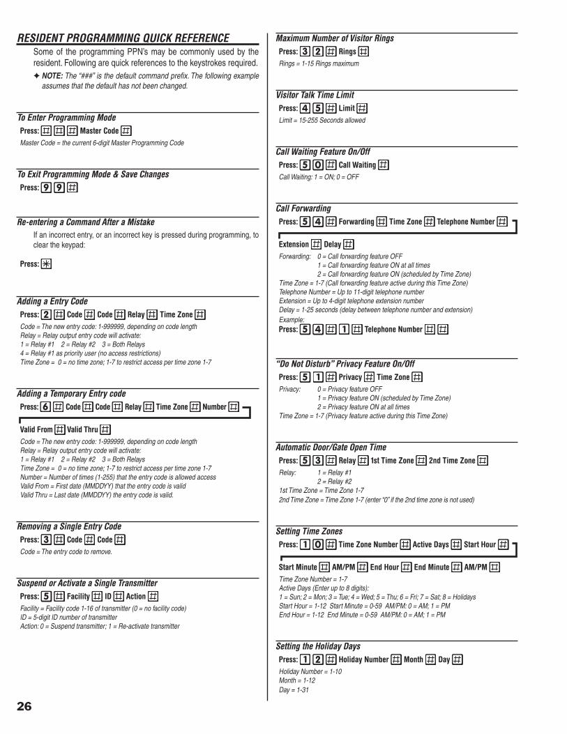
26
RESIDENT PROGRAMMING QUICK REFERENCESome of the programming PPN’s may be commonly used by the resident. Following are quick references to the keystrokes required.✦ NOTE: The “###” is the default command prefi x. The following example
assumes that the default has not been changed.
To Enter Programming ModePress: Master Code Master Code = the current 6-digit Master Programming Code
To Exit Programming Mode & Save ChangesPress:
Re-entering a Command After a MistakeIf an incorrect entry, or an incorrect key is pressed during programming, to clear the keypad:
Press:
Adding a Entry CodePress: Code Code Relay Time Zone Code = The new entry code: 1-999999, depending on code lengthRelay = Relay output entry code will activate:1 = Relay #1 2 = Relay #2 3 = Both Relays4 = Relay #1 as priority user (no access restrictions)Time Zone = 0 = no time zone; 1-7 to restrict access per time zone 1-7
Adding a Temporary Entry codePress: Code Code Relay Time Zone Number
Valid From Valid Thru Code = The new entry code: 1-999999, depending on code lengthRelay = Relay output entry code will activate:1 = Relay #1 2 = Relay #2 3 = Both RelaysTime Zone = 0 = no time zone; 1-7 to restrict access per time zone 1-7Number = Number of times (1-255) that the entry code is allowed accessValid From = First date (MMDDYY) that the entry code is validValid Thru = Last date (MMDDYY) the entry code is valid.
Removing a Single Entry CodePress: Code Code Code = The entry code to remove.
Suspend or Activate a Single TransmitterPress: Facility ID Action Facility = Facility code 1-16 of transmitter (0 = no facility code)ID = 5-digit ID number of transmitterAction: 0 = Suspend transmitter; 1 = Re-activate transmitter
Maximum Number of Visitor RingsPress: Rings Rings = 1-15 Rings maximum
Visitor Talk Time LimitPress: Limit Limit = 15-255 Seconds allowed
Call Waiting Feature On/OffPress: Call Waiting Call Waiting: 1 = ON; 0 = OFF
Call ForwardingPress: Forwarding Time Zone Telephone Number
Extension Delay Forwarding: 0 = Call forwarding feature OFF 1 = Call forwarding feature ON at all times 2 = Call forwarding feature ON (scheduled by Time Zone)Time Zone = 1-7 (Call forwarding feature active during this Time Zone)Telephone Number = Up to 11-digit telephone numberExtension = Up to 4-digit telephone extension numberDelay = 1-25 seconds (delay between telephone number and extension)Example:Press: Telephone Number
“Do Not Disturb” Privacy Feature On/OffPress: Privacy Time Zone Privacy: 0 = Privacy feature OFF 1 = Privacy feature ON (scheduled by Time Zone) 2 = Privacy feature ON at all timesTime Zone = 1-7 (Privacy feature active during this Time Zone)
Automatic Door/Gate Open TimePress: Relay 1st Time Zone 2nd Time Zone Relay: 1 = Relay #1 2 = Relay #21st Time Zone = Time Zone 1-72nd Time Zone = Time Zone 1-7 (enter “0” if the 2nd time zone is not used)
Setting Time ZonesPress: Time Zone Number Active Days Start Hour
Start Minute AM/PM End Hour End Minute AM/PM Time Zone Number = 1-7Active Days (Enter up to 8 digits):1 = Sun; 2 = Mon; 3 = Tue; 4 = Wed; 5 = Thu; 6 = Fri; 7 = Sat; 8 = HolidaysStart Hour = 1-12 Start Minute = 0-59 AM/PM: 0 = AM; 1 = PMEnd Hour = 1-12 End Minute = 0-59 AM/PM: 0 = AM; 1 = PM
Setting the Holiday DaysPress: Holiday Number Month Day Holiday Number = 1-10Month = 1-12Day = 1-31

27
SPECIFICATIONSMECHANICAL
Case dimensions: 6.45” W x 10.81” H x 3.74” DELECTRICAL
Voltage: 16 Volts AC or 12-24 Volts DC Current: 650 mA AC typical, 1300 mA AC maximum Backup Battery: Externally charged 12-24 Volt DC source Backup Battery Current: with 12-volt backup battery 250 mA standby 600 mA ringing one phone 1100 mA maximum with 24-volt backup battery 200 mA standby 350 mA ringing one phone 600 mA maximum Outputs: Relay #1 Form “C” 3 Amps @ 30 Volts maximum Relay #2 Form “C” 3 Amps @ 30 Volts maximum Inputs: Two normally closed door sense/inhibit inputs Two normally open request to exit inputs
RADIO Frequency: 318 Mhz ± 500 KHz @ 23°C RF 3db Bandwidth: 4 MHz Typical Sensitivity: -97 dBm Minimum (-100 dBm Typical) Encoding: Linear MegaCode® Format
ENVIRONMENTAL Temperature: -22°F to 149°F (-30°C to 65°C) Humidity: 5% to 95% non-condensing
DIMENSION DRAWING
TROUBLESHOOTINGSystem will not go into programming mode
1. Wrong master code entered.
System completely dead1. No power from transformer. Check voltage at RE-1 transformer
terminals.2. Verify that terminal blocks are fi rmly plugged into circuit board.
Buzz on speaker1. Check for 24 volt AC power shorted to wiring conduit.2. Check for telephone line shorted to ground.3. Verify that telephone wires are twisted pair.4. Verify that the RE-1 and the Telephone Bypass Module are connected
to earth ground.5. Check 16 VAC voltage at RE-1 transformer terminals.
Buzz on telephone line1. Switch the Telephone Bypass Module to bypass. Connect line ring
and tip to house ring and tip. Check line for buzz with test set.2. Disconnect 16 VAC wires from terminal strip, if buzz goes away, one
side of the transformer wires is grounded.3. Check all connections for any shorts to ground.
Telephones in residence will not ring1. Verify that the “Do Not Disturb” feature is not on while testing.2. Verify that the Call Forwarding feature is not forwarding the calls at
the time.3. Check 16 VAC voltage at RE-1 transformer terminals.4. Disconnect the house telephone line and connect a test telephone to
the RE-1 house ring and tip terminals. See if the test telephone rings.
System will not answer an incoming call1. Modem ring detect (PPN #33) disabled.2. Calling pattern incorrect. Let telephone ring once, hang up, wait 10-30
seconds, then call again.
Call forwarding feature is not working1. Incorrect phone number has been programmed (PPN #54)✦ NOTE: If you are programming the call forwarding feature as “on at all
times”, no programming entry is needed for the time zone (see example in PPN #54).
Entry code will not activate relay1. Entry code not set up for proper relay (PPN #2).2. Time zone is active for the relay.
Remote keypad does not work1. Remote keypad address is not enabled (PPN #28).2. Remote keypad relay is not selected (PPN #23).
Main or remote keypad will not activate a relay1. Keypad is not assigned to a relay (PPN #23).2. Entry code is not assigned to correct relay (PPN #2).
Gate does not open/close at programmed time1. Time was not entered as local time (PPN #20).2. Auto Daylight Saving Time disabled in area that observes daylight
saving (PPN #46).3. Automatic Door/Gate time zone is not properly programmed (PPN
#53).
Relay #1 will not latch from the keypad1. Add an entry code with the relay programmed as a 4 (latch relay #1,
PPN #2).
10.81"
5.95"
6.45" 3.74"
3.39"
MOUNTING PLATE
2.75"
2.75"
.28" DIA.4 PLACES
1.30" DIA.
#8-32 TAPPED

28
PROGRAMMING WORKSHEET
SENOZEMIT SENOZEMIT SENOZEMIT SENOZEMIT SENOZEMIT
SYADEVITCA SYADEVITCA SYADEVITCA SYADEVITCA SYADEVITCA EMITTRATS EMITTRATS EMITTRATS EMITTRATS EMITTRATS EMITDNE EMITDNE EMITDNE EMITDNE EMITDNE
EMIT EMIT EMIT EMIT EMITENOZ ENOZ ENOZ ENOZ ENOZ
NUS NUS NUS NUS NUS NOM NOM NOM NOM NOM EUT EUT EUT EUT EUT DEW DEW DEW DEW DEW UHT UHT UHT UHT UHT IRF IRF IRF IRF IRF TAS TAS TAS TAS TAS SYADILOH SYADILOH SYADILOH SYADILOH SYADILOH RUOH RUOH RUOH RUOH RUOH ETUNIM ETUNIM ETUNIM ETUNIM ETUNIM MP/MA MP/MA MP/MA MP/MA MP/MA RUOH RUOH RUOH RUOH RUOH ETUNIM ETUNIM ETUNIM ETUNIM ETUNIM MP/MA MP/MA MP/MA MP/MA MP/MA
11111
22222
33333
44444
55555
66666
77777
SYADILOH SYADILOH SYADILOH SYADILOH SYADILOH
YADILOH YADILOH YADILOH YADILOH YADILOH EMAN EMAN EMAN EMAN EMAN HTNOM HTNOM HTNOM HTNOM HTNOM YAD YAD YAD YAD YAD
11111
22222
33333
44444
55555
66666
77777
88888
99999
0101010101
EDOCRETSAM EDOCRETSAM EDOCRETSAM EDOCRETSAM EDOCRETSAM
REBMUNGNIDRAWROFLLAC REBMUNGNIDRAWROFLLAC REBMUNGNIDRAWROFLLAC REBMUNGNIDRAWROFLLAC REBMUNGNIDRAWROFLLAC
1REBMUNENOHPELETETANRETLA 1REBMUNENOHPELETETANRETLA 1REBMUNENOHPELETETANRETLA 1REBMUNENOHPELETETANRETLA 1REBMUNENOHPELETETANRETLA
2REBMUNENOHPELETETANRETLA 2REBMUNENOHPELETETANRETLA 2REBMUNENOHPELETETANRETLA 2REBMUNENOHPELETETANRETLA 2REBMUNENOHPELETETANRETLA
3REBMUNENOHPELETETANRETLA 3REBMUNENOHPELETETANRETLA 3REBMUNENOHPELETETANRETLA 3REBMUNENOHPELETETANRETLA 3REBMUNENOHPELETETANRETLA
SYSTEM PROGRAMMINGFEATURE PPN DEFAULT NEW VALUE
ENTRY CODE LENGTH 1 4
TX LEFT BUTTON 8 RELAY #1
TX RIGHT BUTTON 8 RELAY #2
TX TOP BUTTON 8 RELAYS #1 & #2
TX LOWER LEFT BUTTON 8 NONE
TX LOWER RIGHT BUTTON 8 NONE
RELAY #1 ON TIME 21 2 SECONDS
RELAY #2 ON TIME 22 2 SECONDS
MAIN KEYPAD ACTIVATES 23 RELAY #1
REMOTE KEYPAD ACTIVATES 23 RELAY #2
RELAY #2 ALARM FUNCTION 24 DISABLED
MGT GATE EDGE TRANSMITTER 26 DISABLED
RELAY #2 ALTERNATE FUNCTION 27 ACCESS RELAY
REMOTE KEYPAD ADDRESS 28 3
RELAY #1 SENSE OR INHIBIT 29 SENSE
RELAY #2 SENSE OR INHIBIT 29 SENSE
KEYPAD LOCKOUT COUNT 30 5 TRIES
ANTI-PASSBACK TIME 31 OFF
MAXIMUM VISITOR CALL RINGS 32 5 RINGS
MODEM RING DETECT 33 ON
CALL FORWARDING DIALING METHOD 34 TONE
KEYPAD BEEPS 40 ON
RELAY #1 TONE 41 OFF
RELAY #2 TONE 42 OFF
RELAY TONE DURATION 43 1 SECOND
VOICE SYNTHESIZER 44 ON
VISITOR TALK TIME LIMIT 45 60 SECONDS
AUTOMATIC DAYLIGHT SAVINGS TIME ADJUSTMENT 46 ON
CALL WAITING FEATURE 50 ON
PRIVACY FEATURE 51 OFF
AUTOMATIC DOOR/GATE OPEN TIME 53 NOT SET
CALL FORWARDING FEATURE 54 OFF
ALTERNATE RESIDENT TELEPHONE NUMBERS 55 ALL DISABLED
RESIDENT RESPONSE TELEPHONE KEY FOR RELAY #1 71 1
RESIDENT RESPONSE TELEPHONE KEY FOR RELAY #2 71 2
RESIDENT RESPONSE TELEPHONE KEY FOR VISITOR DISCONNECT
71 9
RESIDENT RESPONSE TELEPHONE KEY FOR SWITCH TO/FROM CALL WAITING
71 6
RESIDENT PROGRAMMING PREFIX 72 ###
RESIDENT COMMAND PREFIX 72 ##

29
EDOCYRTNE EDOCYRTNE EDOCYRTNE EDOCYRTNE EDOCYRTNE #YALER #YALER #YALER #YALER #YALER ENOZEMIT ENOZEMIT ENOZEMIT ENOZEMIT ENOZEMIT EDOCYRTNE EDOCYRTNE EDOCYRTNE EDOCYRTNE EDOCYRTNE #YALER #YALER #YALER #YALER #YALER ENOZEMIT ENOZEMIT ENOZEMIT ENOZEMIT ENOZEMIT
2__1__ 2__1__
2__1__ 2__1__
2__1__ 2__1__
2__1__ 2__1__
2__1__ 2__1__
2__1__ 2__1__
2__1__ 2__1__
2__1__ 2__1__
2__1__ 2__1__
2__1__ 2__1__
2__1__ 2__1__
2__1__ 2__1__
2__1__ 2__1__
2__1__ 2__1__
2__1__ 2__1__
2__1__ 2__1__
2__1__ 2__1__
2__1__ 2__1__
2__1__ 2__1__
2__1__ 2__1__
2__1__ 2__1__
2__1__ 2__1__
2__1__ 2__1__
2__1__ 2__1__
2__1__ 2__1__
2__1__ 2__1__
2__1__ 2__1__
2__1__ 2__1__
2__1__ 2__1__
2__1__ 2__1__
2__1__ 2__1__
2__1__ 2__1__
2__1__ 2__1__
2__1__ 2__1__
2__1__ 2__1__
2__1__ 2__1__
2__1__ 2__1__
2__1__ 2__1__
2__1__ 2__1__
2__1__ 2__1__
2__1__ 2__1__
2__1__ 2__1__
2__1__ 2__1__
2__1__ 2__1__
2__1__ 2__1__
2__1__ 2__1__
2__1__ 2__1__
2__1__ 2__1__
2__1__ 2__1__
2__1__ 2__1__
RESURETTIMSNART RESURETTIMSNART RESURETTIMSNART RESURETTIMSNART RESURETTIMSNART YTILICAF YTILICAF YTILICAF YTILICAF YTILICAFEDOC EDOC EDOC EDOC EDOC EDOCDI EDOCDI EDOCDI EDOCDI EDOCDI ENOZEMITTS1 ENOZEMITTS1 ENOZEMITTS1 ENOZEMITTS1 ENOZEMITTS1 ENOZEMITDN2 ENOZEMITDN2 ENOZEMITDN2 ENOZEMITDN2 ENOZEMITDN2 PUORGXT PUORGXT PUORGXT PUORGXT PUORGXT

LINEAR LIMITED WARRANTYThis Linear product is warranted against defects in material and workmanship for twenty-four (24) months. The Warranty Expiration Date is labeled on the product. This warranty extends only to wholesale customers who buy direct from Linear or through Linear’s normal distribution channels. Linear does not warrant this product to consumers. Consumers should inquire from their selling dealer as to the nature of the dealer’s warranty, if any. There are no obligations or liabilities on the part of Linear LLC for consequential damages arising out of or in connection with use or performance of this product or other indirect damages with respect to loss of property, revenue, or profi t, or cost of removal, installation, or reinstallation. All implied warranties, including implied warranties for merchantability and implied warranties for fi tness, are valid only until Warranty Expiration Date as labeled on the product. This Linear LLC Warranty is in lieu of all other warranties express or implied.All products returned for warranty service require a Return Product Authorization Number (RPA#). Contact Linear Technical Services at 1-800-421-1587 for an RPA# and other important details.
IMPORTANT WIRELESS INFORMATIONLinear radio controls provide a reliable communications link and fi ll an important need in portable wireless signaling. However, there are some limitations which must be observed.• For U.S. installations only: The radios are required to comply with FCC
Rules and Regulations as Part 15 devices. As such, they have limited transmitter power and therefore limited range.
• A receiver cannot respond to more than one transmitted signal at a time and may be blocked by radio signals that occur on or near their operating frequencies, regardless of code settings.
• Changes or modifi cations to the device may void FCC compliance.
• Infrequently used radio links should be tested regularly to protect against undetected interference or fault.
• A general knowledge of radio and its vagaries should be gained prior to acting as a wholesale distributor or dealer, and these facts should be communicated to the ultimate users.
FCC NOTICEChanges or modifi cations not expressly described in this manual or approved by the manufacturer could void the user’s authority to operate the equipment.This equipment has been tested and found to comply with the limits for a Class B digital device, pursuant to Part 15 of the FCC Rules. These limits are designed to provide reasonable protection against harmful interference in a residential installation. This equipment generates, uses and can radiate radio frequency energy and, if not installed and used in accordance with the instructions, may cause harmful interference to radio communications. However, there is no guarantee that interference will not occur in a particular installation. If this equipment does cause harmful interference to radio or television reception, which can be determined by turning the equipment off and on, the user is encouraged to try to correct the interference by one or more of the following measures:• Reorient or relocate the receiving antenna.
• Increase the separation between the equipment and receiver.
• Connect the equipment into an outlet on a circuit different from that to which the receiver is connected.
• Consult the dealer or an experienced radio/TV technician for help.
Copyright © 2008 Linear LLC 217490 C