Control of Permanent Magnet Linear Synchronous Motor in Motion Control Applications
7/29/2019 LINEAR MOTION CONTROL
http://slidepdf.com/reader/full/linear-motion-control 1/12
Precision Roller Pinion SystemPremium and Standard Models
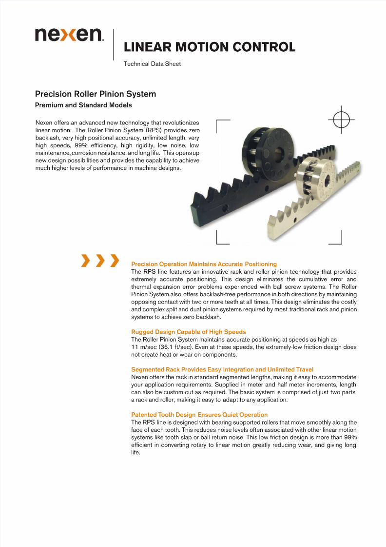
Nexen o ers an advanced new technolog that revolutionizeslinear motion. The Roller Pinion S stem (RPS) provides zerobacklash, ver high positional accurac , unlimited length, verhigh speeds, 99% e cienc , high rigidit , low noise, lowmaintenance, corrosion resistance, and long li e. This opens upnew design possibilities and provides the capabilit to achievemuch higher levels o per ormance in machine designs.
LINEAR MOTION CONTROLTechnical Data Sheet
Precision Operation Maintains Accurate PositioningThe RPS line eatures an innovative rack and roller pinion technolog that providesextremel accurate positioning. This design eliminates the cumulative error and
thermal expansion error problems experienced with ball screw s stems. The RollerPinion S stem also o ers backlash- ree per ormance in both directions b maintainingopposing contact with two or more teeth at all times. This design eliminates the costland complex split and dual pinion s stems required b most traditional rack and pinions stems to achieve zero backlash.
Rugged Design Capable o High SpeedsThe Roller Pinion S stem maintains accurate positioning at speeds as high as11 m/sec (36.1 t/sec). Even at these speeds, the extremel -low riction design doesnot create heat or wear on components.
Segmented Rack Provides Easy Integration and Unlimited TravelNexen o ers the rack in standard segmented lengths, making it eas to accommodate
our application requirements. Supplied in meter and hal meter increments, lengthcan also be custom cut as required. The basic s stem is comprised o just two parts,a rack and roller, making it eas to adapt to an application.
Patented Tooth Design Ensures Quiet OperationThe RPS line is designed with bearing supported rollers that move smoothl along the
ace o each tooth. This reduces noise levels o ten associated with other linear motions stems like tooth slap or ball return noise. This low riction design is more than 99%e cient in converting rotar to linear motion greatl reducing wear, and giving longli e.
7/29/2019 LINEAR MOTION CONTROL
http://slidepdf.com/reader/full/linear-motion-control 2/12
Zero Backlash/High Precision
The RPS’s innovative meshing action provides backlash o less than 3.2 µ m [0.00013 in] and due to the extremelprecise manu acturing process provides positional accurac up to ± 20 µ m [± 0.00079 in]. Each tooth pro ile is preciselmeasured relative to the irst to ensure that high positional accurac is maintained and cumulative error is eliminated.Due to the strong tooth and roller design the RPS is ver rigid. Within the load rating o each size it can be consideredper ectl rigid and is re lected in the positional accurac ratings.
Unlimited Run Lengths Possible
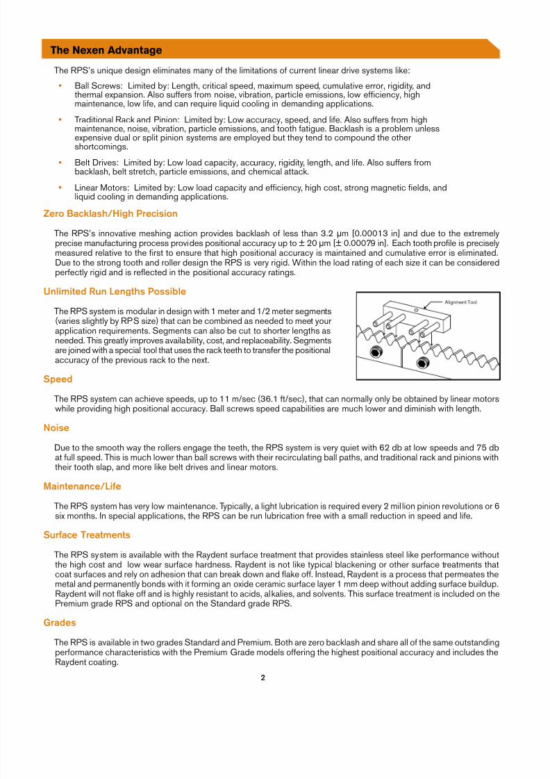
The RPS s stem is modular in design with 1 meter and 1/2 meter segments(varies slightl b RPS size) that can be combined as needed to meet ourapplication requirements. Segments can also be cut to shorter lengths asneeded. This greatl improves availabilit , cost, and replaceabilit . Segmentsare joined with a special tool that uses the rack teeth to trans er the positionalaccurac o the previous rack to the next.
Speed
The RPS s stem can achieve speeds, up to 11 m/sec (36.1 t/sec), that can normall onl be obtained b linear motors
while providing high positional accurac . Ball screws speed capabilities are much lower and diminish with length.Noise
Due to the smooth wa the rollers engage the teeth, the RPS s stem is ver quiet with 62 db at low speeds and 75 dbat ull speed. This is much lower than ball screws with their recirculating ball paths, and traditional rack and pinions withtheir tooth slap, and more like belt drives and linear motors.
Maintenance/Li e
The RPS s stem has ver low maintenance. T picall , a light lubrication is required ever 2 million pinion revolutions or 6six months. In special applications, the RPS can be run lubrication ree with a small reduction in speed and li e.
Sur ace Treatments
The RPS s stem is available with the Ra dent sur ace treatment that provides stainless steel like per ormance withoutthe high cost and low wear sur ace hardness. Ra dent is not like t pical blackening or other sur ace treatments thatcoat sur aces and rel on adhesion that can break down and lake o . Instead, Ra dent is a process that permeates themetal and permanentl bonds with it orming an oxide ceramic sur ace la er 1 mm deep without adding sur ace buildup.Ra dent will not lake o and is highl resistant to acids, alkalies, and solvents. This sur ace treatment is included on thePremium grade RPS and optional on the Standard grade RPS.
Grades
The RPS is available in two grades Standard and Premium. Both are zero backlash and share all o the same outstandingper ormance characteristics with the Premium Grade models o ering the highest positional accurac and includes theRa dent coating.
Alignment Tool
Overcomes the Limitations o Other Linear Motion Products
The RPS’s unique design eliminates man o the limitations o current linear drive s stems like:
• Ball Screws: Limited b : Length, critical speed, maximum speed, cumulative error, rigidit , andthermal expansion. Also su ers rom noise, vibration, particle emissions, low e cienc , highmaintenance, low li e, and can require liquid cooling in demanding applications.
• Traditional Rack and Pinion: Limited b : Low accurac , speed, and li e. Also su ers rom highmaintenance, noise, vibration, particle emissions, and tooth atigue. Backlash is a problem unlessexpensive dual or split pinion s stems are emplo ed but the tend to compound the othershortcomings.
• Belt Drives: Limited b : Low load capacit , accurac , rigidit , length, and li e. Also su ers rombacklash, belt stretch, particle emissions, and chemical attack.
• Linear Motors: Limited b : Low load capacit and e cienc , high cost, strong magnetic elds, andliquid cooling in demanding applications.
The Nexen Advantage
7/29/2019 LINEAR MOTION CONTROL
http://slidepdf.com/reader/full/linear-motion-control 3/12
The RPS s stem achieves its incredible per ormance b using a pinion consisting o bearing supported rollers thatengage a unique tooth pro ile. Two or more rollers engage the rack teeth in opposition at all times eliminating backlash.There is no tooth slap as with traditional rack and pinion, instead the RPS rollers approach the tooth ace in a tangent
path and then roll smoothl down the tooth ace. This provides a smooth, quiet, low riction, atigue ree, high e iciencrotar to linear motion conversion.
The RPS tooth design is conceptuall di erent rom traditional rack and pinion designs. It behaves like a cam and ollowerversus the t pical sliding spur gear used with traditional rack and pinion. As illustrated in the igures below, a c cloidalcurve is created when a point drawn on a circle at point P rolls on a lat plane to point P’ without slipping. When multiplepoints are placed on the circle at regular intervals, the c cloidal curves are repeatedl created on the lat plane, anddevelop into a tooth-like pro ile.
A roller then is placed at each point P to act as pinion teeth and modi ies the tooth pro ile to create the rack teeth. Normall ,this concept will not provide zero backlash, but a technical innovation was developed to modi the tooth geometrallowing two rollers to remain loaded in opposition at all times eliminating the backlash as the rollers engage the rack.The rollers meet the rack smoothl and eliminate tooth slap, sliding riction, atigue, noise, and low precision associatedwith traditional rack and pinion. Both the rollers and tooth aces are hardened to the upper RC50’s or exceptionall long
service li e.
How the RPS Works
P
P'
Rollers inOpposition
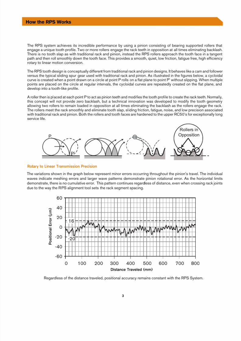
The variations shown in the graph below represent minor errors occurring throughout the pinion’s travel. The individual
waves indicate meshing errors and larger wave patterns demonstrate pinion rotational error. As the horizontal limitsdemonstrate, there is no cumulative error. This pattern continues regardless o distance, even when crossing rack jointsdue to the wa the RPS alignment tool sets the rack segment spacing.
-60
-40
-20
0
20
40
60
8007006005004003002001000
-20
16
Distance Traveled (mm)
P o s
i t i o n a
l E r r o r
( µ m
)
Regardless o the distance traveled, positional accurac remains constant with the RPS S stem.
Rotary to Linear Transmission Precision
7/29/2019 LINEAR MOTION CONTROL
http://slidepdf.com/reader/full/linear-motion-control 4/12
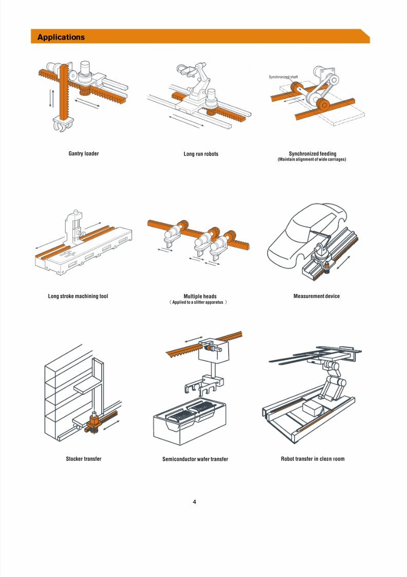
Applications
Synchronized shaft
redaolyrtnaG Synchronized feeding(Maintain alignment of wide carriages)
Long stroke machining tool Multiple headsApplied to a slitter apparatus
Measurement device
moornaelcnirefsnarttoboRrefsnartrekcotS
Long run robots
Semiconductor wafer transfer
7/29/2019 LINEAR MOTION CONTROL
http://slidepdf.com/reader/full/linear-motion-control 5/12
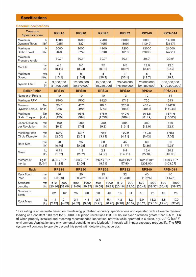
General Specifcations
CommonSpecifcations RPS16 RPS 0 RPS RPS RPS 0 RPS 01
MaximumD namic Thrust
N[lb ]
1000[225]
1500[337]
2200[495]
3600[809]
6000[1349]
14000[3147]
MaximumStatic Thrust
N[lb ]
2000[450]
3000[674]
4400[990]
7200[1618]
12000[2698]
21000[4721]
MaximumPressure Angle 30.7º 30.1º 30.7º 30.1º 30.0º 30.0º
Module mm[in]
4.8[0.19]
6.0[0.24]
7.5[0.30]
9.5[0.37]
12.0[0.47]
12.0[0.47]
MaximumSpeed
m/s[ t/s]
4[13.1]
5[16.4]
8[26.2]
11[36.1]
6[19.7]
6[19.7]
S stem Li e * m[ t]
9,600,000[31,496,000]
12,000,000[39,370,000]
15,000,000[49,230,000]
23,040,000[75,590,000]
28,800,000[94,480,000]
336,000,000[1,102,200,000]
Roller Pinion RPS16 RPS 0 RPS RPS RPS 0 RPS 01
Number o Rollers 10 10 10 12 12 14Maximum RPM 1500 1500 1920 1719 750 643MaximumD namic Torque
Nm[in-lb]
25.5[226]
47.7[422]
88.0[774]
220.0[1946]
458.4[4057]
1247.8[11044]
MaximumStatic Torque
Nm[in-lb]
50.9[450]
95.5[884]
176.0[1558]
440.0[3894]
916.8[8119]
1871.6[16565]
Linear Distanceper Revolution
mm[in]
160[6.3]
200[7.9]
250[9.8]
384[15.1]
480[18.9]
560[22.1]
Meshing PitchCircle Diameter
mm[in]
50.9[2.00]
63.7[2.51]
79.6[3.13]
122.2[4.81]
152.8[6.02]
178.3[7.02]
Bore Size mm
[in]
20
[0.79]
25
[0.98]
30
[1.18]
45
[1.77]
60
[2.36]
60
[2.36]
Mass kg[lb]
0.71[1.57]
1.3[2.87]
2.1[4.63]
6.4[14.11]
12.4[27.34]
20.9[46.08]
Moment oInertia
kg-m2 [lb-in2]
3.93 x 10 -4 [1.34]
10.5 x 10 -4 [3.59]
25.5 x 10 -4 [8.71]
169 x 10 -4 [57.80]
594 x 10 -4 [203.00]
1180 x 10 -4 [403.27]
Rack RPS16 RPS 0 RPS RPS RPS 0 RPS 01
Rack ToothPitch
mm[in]
16[.0630]
20[0.787]
25[0.984]
32[1.260]
40[1.575]
40[1.575]
StandardLengths
mm[in]
512[20.16]
992[39.06]
500[19.69]
1000[39.37]
500[19.69]
1000[39.37]
512[20.16]
992[39.06]
520[20.47]
1000[39.37]
520[20.47]
1000[39.37]
Number oTeeth 32 62 25 50 20 40 16 31 13 25 13 25
Rack Mass kg[lb]
1.1[2.43]
2.1[4.63]
2.1[4.63]
4.1[9.04]
2.7[5.95]
5.4[16.90]
4.2[9.26]
8.2[18.09]
6.9[15.21]
13.2[29.10]
8.8[19.40]
17.0[37.48]
* Li e rating is an estimate based on maintaining published accurac speci cations and operated with allowable d namicloading at a constant 100 rpm or 60,000,000 pinion revolutions (10,000 hours) over distances greater than 0.5 m [1.6
t] when properl installed and receiving recommended lubrication intervals while operated in a clean, dr , 20° C [68° F]environment. Application and environmental conditions, and lubrication intervals will impact expected product li e. The RPSs stem will continue to operate be ond this point with deteriorating accurac .
Specifcations
7/29/2019 LINEAR MOTION CONTROL
http://slidepdf.com/reader/full/linear-motion-control 6/12
6
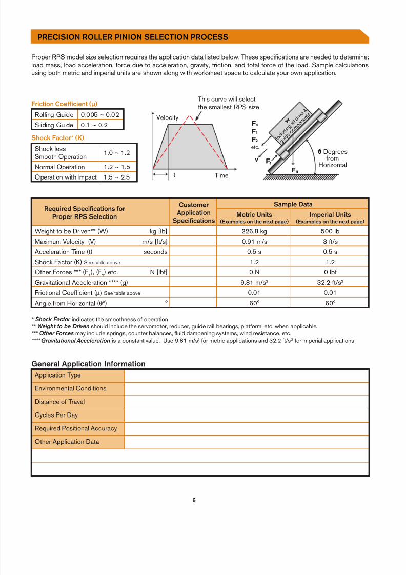
Proper RPS model size selection requires the application data listed below. These speci cations are needed to determine:load mass, load acceleration, orce due to acceleration, gravit , riction, and total orce o the load. Sample calculationsusing both metric and imperial units are shown along with worksheet space to calculate our own application.
Required Specifcations orProper RPS Selection
CustomerApplication
Specifcations
Sample Data
Metric Units(Examples on the next page)
Imperial Units(Examples on the next page)
Weight to be Driven** (W) kg [lb] 226.8 kg 500 lbMaximum Velocit (V) m/s [ t/s] 0.91 m/s 3 t/sAcceleration Time (t) seconds 0.5 s 0.5 sShock Factor (K) See table above 1.2 1.2Other Forces *** (F 1 ), (F2) etc. N [lb ] 0 N 0 lbGravitational Acceleration **** (g) 9.81 m/s 2 32.2 t/s2
Frictional Coe cient (µ) See table above 0.01 0.01
Angle rom Horizontal (θ°) ° 60° 60°
* Shock Factor indicates the smoothness o operation** Weight to be Driven should include the servomotor, reducer, guide rail bearings, plat orm, etc. when applicable.*** Other Forces ma include springs, counter balances, fuid dampening s stems, wind resistance, etc.**** Gravitational Acceleration is a constant value. Use 9.81 m/s 2 or metric applications and 32.2 t/s 2 or imperial applications
w
I n c l u d
i n g a l ld
r i v e&
g u i d ec o m p
o n e n
t s
0 Degreesfrom
HorizontalF g
F 2
F 1
F a
Ff
etc.
v
Time
Velocity
t
Friction Coe fcient (µ)
Rolling Guide 0.005 ~ 0.02Sliding Guide 0.1 ~ 0.2
Shock Factor* (K)
Shock-lessSmooth Operation 1.0 ~ 1.2
Normal Operation 1.2 ~ 1.5Operation with Impact 1.5 ~ 2.5
General Application In ormationApplication T pe
Environmental Conditions
Distance o TravelC cles Per Da
Required Positional Accurac
Other Application Data
This curve will selectthe smallest RPS size
PRECISION ROLLER PINION SELECTION PROCESS
7/29/2019 LINEAR MOTION CONTROL
http://slidepdf.com/reader/full/linear-motion-control 7/12
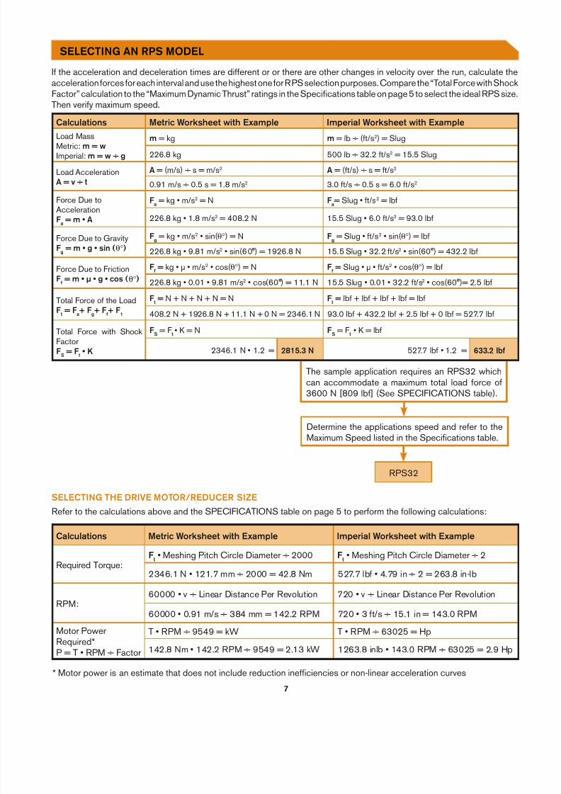
The sample application requires an RPS32 whichcan accommodate a maximum total load orce o3600 N [809 lb ] (See SPECIFICATIONS table).
I the acceleration and deceleration times are di erent or or there are other changes in velocit over the run, calculate theacceleration orces or each interval and use the highest one or RPS selection purposes. Compare the “Total Force with Shock Factor” calculation to the “Maximum D namic Thrust” ratings in the Speci cations table on page 5 to select the ideal RPS size.Then veri maximum speed.
Calculations Metric Worksheet with Example Imperial Worksheet with Example
Load MassMetric: m = wImperial: m = w ÷ g
m = kg m = lb ÷ ( t/s2) = Slug226.8 kg 500 lb ÷ 32.2 t/s 2 = 15.5 Slug
Load AccelerationA = v ÷ t
A = (m/s) ÷ s = m/s 2 A = ( t/s) ÷ s = t/s 2
0.91 m/s ÷ 0.5 s = 1.8 m/s 2 3.0 t/s ÷ 0.5 s = 6.0 t/s 2
Force Due toAccelerationFa = m • A
Fa = kg • m/s 2 = N Fa= Slug • t/s 2 = lb
226.8 kg • 1.8 m/s 2 = 408.2 N 15.5 Slug • 6.0 t/s 2 = 93.0 lb
Force Due to GravitFg = m • g • sin ( θ° )
Fg = kg • m/s 2 • sin(θ° ) = N Fg = Slug • t/s 2 • sin(θ° ) = lb
226.8 kg • 9.81 m/s 2 • sin(60°) = 1926.8 N 15.5 Slug • 32.2 t/s 2 • sin(60°) = 432.2 lb
Force Due to FrictionF = m • µ • g • cos ( θ° )
F = kg • μ • m/s 2 • cos( θ° ) = N F = Slug • μ • t/s2 • cos( θ° ) = lb
226.8 kg • 0.01 • 9.81 m/s 2 • cos(60°) = 11.1 N 15.5 Slug • 0.01 • 32.2 t/s 2 • cos(60°)= 2.5 lb
Total Force o the LoadFt = F a+ F g+ F + F 1
Ft = N + N + N + N = N Ft = lb + lb + lb + lb = lb
408.2 N + 1926.8 N + 11.1 N + 0 N = 2346.1 N 93.0 lb + 432.2 lb + 2.5 lb + 0 lb = 527.7 lb
Total Force with Shock FactorFS = F t • K
FS = F t • K = N FS = F t • K = lb
2346.1 N • 1.2 = 81 . N 527.7 lb • 1.2 = 6 . lb
Calculations Metric Worksheet with Example Imperial Worksheet with Example
Required Torque: Ft • Meshing Pitch Circle Diameter ÷ 2000 Ft • Meshing Pitch Circle Diameter ÷ 22346.1 N • 121.7 mm ÷ 2000 = 42.8 Nm 527.7 lb • 4.79 in ÷ 2 = 263.8 in-lb
RPM:60000 • v ÷ Linear Distance Per Revolution 720 • v ÷ Linear Distance Per Revolution
60000 • 0.91 m/s ÷ 384 mm = 142.2 RPM 720 • 3 t/s ÷ 15.1 in = 143.0 RPM
Motor PowerRequired*P = T • RPM ÷ Factor
T • RPM ÷ 9549 = kW T • RPM ÷ 63025 = Hp
142.8 Nm • 142.2 RPM ÷ 9549 = 2.13 kW 1263.8 inlb • 143.0 RPM ÷ 63025 = 2.9 Hp
RPS32
Determine the applications speed and re er to theMaximum Speed listed in the Speci cations table.
SELECTING AN RPS MODEL
Re er to the calculations above and the SPECIFICATIONS table on page 5 to per orm the ollowing calculations:SELECTING THE DRIVE MOTOR/REDUCER SIZE
* Motor power is an estimate that does not include reduction ine ciencies or non-linear acceleration curves
7/29/2019 LINEAR MOTION CONTROL
http://slidepdf.com/reader/full/linear-motion-control 8/12
8
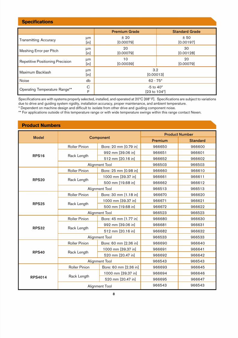
Model ComponentProduct Number
Premium Standard
RPS16
Roller Pinion Bore: 20 mm [0.79 in] 966650 966600
Rack Length992 mm [39.06 in] 966651 966601512 mm [20.16 in] 966652 966602
Alignment Tool 966503 966503
RPS 0
Roller Pinion Bore: 25 mm [0.98 in] 966660 966610
Rack Length 1000 mm [39.37 in] 966661 966611500 mm [19.68 in] 966662 966612
Alignment Tool 966513 966513
RPS
Roller Pinion Bore: 30 mm [1.18 in] 966670 966620
Rack Length1000 mm [39.37 in] 966671 966621500 mm [19.68 in] 966672 966622
Alignment Tool 966523 966523
RPS
Roller Pinion Bore: 45 mm [1.77 in] 966680 966630
Rack Length992 mm [39.06 in] 966681 966631
512 mm [20.16 in] 966682 966632
Alignment Tool 966533 966533
RPS 0
Roller Pinion Bore: 60 mm [2.36 in] 966690 966640
Rack Length1000 mm [39.37 in] 966691 966641520 mm [20.47 in] 966692 966642
Alignment Tool 966543 966543
RPS 01
Roller Pinion Bore: 60 mm [2.36 in] 966693 966645
Rack Length1000 mm [39.37 in] 966694 966646520 mm [20.47 in] 966695 966647
Alignment Tool 966543 966543
Premium Grade Standard Grade
Transmitting Accurac µm[in]
± 20[0.00079]
± 50[0.00197]
Meshing Error per Pitch µm[in]
20[0.00079]
30[0.00128]
Repetitive Positioning Precision µm[in]
10[0.00039]
20[0.00079]
Maximum Backlash µm[in]
3.2[0.00013]
Noise db 62 - 75*
Operating Temperature Range** CF
-5 to 40º[23 to 104º]
Specifcations
Product Numbers
Speci cations are with s stems properl selected, installed, and operated at 20ºC [68º F]. Speci cations are subject to variationsdue to drive and guiding s stem rigidit , installation accurac , proper maintenance, and ambient temperature.* Dependent on machine design and di cult to isolate rom other drive and guiding component noise.** For applications outside o this temperature range or with wide temperature swings within this range contact Nexen.
7/29/2019 LINEAR MOTION CONTROL
http://slidepdf.com/reader/full/linear-motion-control 9/12
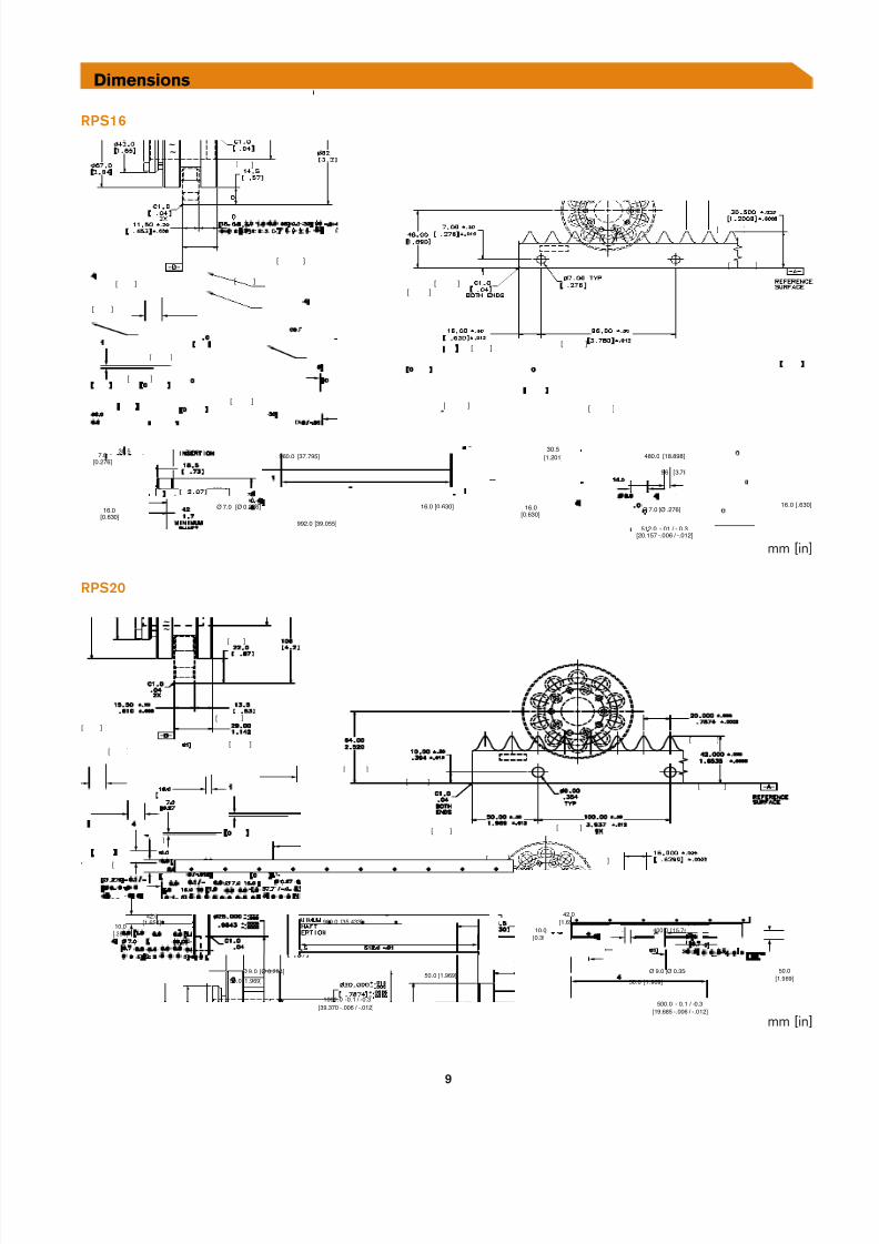
RPS16
RPS 0
Dimensions
mm [in]
[ ]
[ ]
[ ]
[ ]
[ ]
[ ]
[ ]
[ ]
[ ] [ ]
[ ]
[ ]
[ ][ ]
~
~
42.0[1.6 54]
1000.0 - 0.1 / - 0. 3[39.3 70 -.0 06 / -.012]
42.0[1.6 54]
500.0 - 0.1 / - 0.3[19.6 85 -.0 06 / -.01 2]
10.0[.394]
50.0 [1.9 69]
10 0.0 [3.9 37]
[35.4 33]900.0
50.0 [ 1. 969][Ø 0. 354]Ø 9.0
10.0[0.3 94]
50.0 [1.9 69]
[Ø 0. 354]Ø 9.0
400.0 [1 5.7 48]
50.0[1.9 69]
[ ]
[ ]
[ ]
[ ]
[ ]
[ ]
[ ]
[ ]
[ ]
[ ]
[ ][ ]
[ ]
[ ] [ ]
[ ]
[ ]
[ ]
30.5[1.2 01]
16.0[0.63 0]
96.0 [3.7 80]
960.0 [37.7 95]
[39.05 5]992.0
[Ø 0.27 6]Ø 7.0
30.5[1.201]
16.0[0.6 30]
96 [3.7 80]
[18. 898]48 0.0
512.0 -.01 / -.0. 3[20.157 -.0 06 / -.012]
Ø 7.0 [Ø .276]16.0 [.6 30]
7.0[0.27 6]
16.0 [ 0.6 30]
~
~
mm [in]
7/29/2019 LINEAR MOTION CONTROL
http://slidepdf.com/reader/full/linear-motion-control 10/12
10
[ ] [ ]
[ ]
[ ]
[ ]
[ ][ ]
[ ]
[ ]
[ ]
[ ][ ]
[ ]
[ ]
[ ]
[ ]
~
~
48.0[1.891]
10 00.0 - 0.1 / - 0.3[39.3 70 -.0 06 / -.01 2]
48.0[1.8 91 ]
500.0 - 0.1 / - 0.3[19.6 85 -.0 06 / -.012]
12.0[0.4 73]
50.0 [1.9 69]
10 0.0 [ 3.9 37 ]
[35.4 33]900.0
50.0 [1.9 69]Ø 11.0 [Ø 0.4 33]
12.0[0.4 73]
50.0 [1. 969]
[Ø 0.4 33]Ø 11.0
400.0 [1 5.7 48]
50.0[1.969]
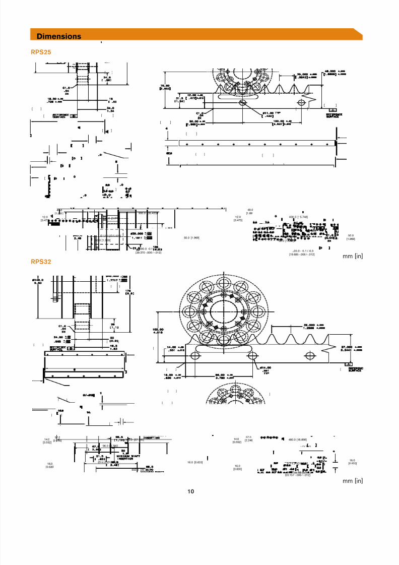
RPS
RPS
57.0[2.246]
16.0[0.6 30]
96.0 [ 3.7 80]
[37.7 95]960.0
[39.0 55]992.0
Ø1 4.0 [ Ø 0. 552] 16.0 [0.6 30]
57.0[2.2 46]
16.0[0.6 30]
96.0 [ 3.7 80]
[18. 898]480.0
512.0 -.01 / -.0.3[20.15 7 -.0 06 / -.012]
Ø 1 4.0 [ Ø 0. 552]16.0
[0.6 30]
14.0[0.552]
14. 0[0.552]
[ ]
[ ]
[ ]
[ ]
[ ]
[ ]
[ ]
[ ]
[ ]
[ ] [ ]
[ ]
[ ]
[ ]
~
~
mm [in]
mm [in]
Dimensions

7/29/2019 LINEAR MOTION CONTROL
http://slidepdf.com/reader/full/linear-motion-control 11/12
11
RPS 0
[ ]
[ ]
[ ]
[ ]
[ ]
[ ]
[ ]
[ ] [ ]
[ ]
[ ]
[ ]
[ ]
72.6[2.8 60]
1000.0 -0.1 / -0 .3[39.370 - .006 / - .012 ]
72.6[2.860]
520. 0 - 0.1 / - 0.3[20.488 - .006 / - .012 ]
16 .0[0.630]
80.0 [3.152]
12 0.0 [4.728]
[33.096]840.0
80.0 [3.152]Ø 18 .0 [Ø 0 .709]
16 .0[0.630]
80.0 [3.15 2]
Ø 18 .0 [ Ø 0 .709]
360.0 [14 .18 4]
80.0[3.152]
[ ]
mm [in]RPS 01
mm [in]
Dimensions
72.6[2.860]
1000.0 -0.1 / -0.3[39.370 - .006 / -.012 ]
72.6[2.860]
520. 0 - 0 .1 / -0.3[20.488 - .006 / -.01 2]
16.0[0.630]
80.0 [3.15 2]
120.0 [4.728]
[33.096]840.0
80.0 [3.152]Ø 18 .0 [Ø 0 .709]
16 .0 .[0.630]
80.0 [3.15 2]
Ø 1 8.0 [Ø 0 .709]
360.0 [14.184]
80.0[3.152]
[ ][ ][ ]
[ ]
[ ]
[ ]
[ ]
[ ]
[ ]
[ ]
[ ]
7/29/2019 LINEAR MOTION CONTROL
http://slidepdf.com/reader/full/linear-motion-control 12/12
ISO 9001 Certi ed
Nexen has sales o ces throughout the United States,Europe, Japan, and Australia.
www.nexengroup.com
In accordance with Nexen’s established polic o constant productimprovement, the speci cations contained in this document are subjectto change without notice. Technical data listed in this document arebased on the latest in ormation available at the time o printing and arealso subject to change without notice. For current in ormation, pleaseconsult www.nexengroup.com
Nexen Group, Inc.560 Oak Grove ParkwaVadnais Heights, MN 55127
(800) 843-7445Fax: (651) 286-1099www.nexengroup.com
©2008 Nexen Group, Inc. 21238-C-0108
CUTTING SySTEMS
GANTRy SySTEMSMEDICAL PRODUCTS
ROBOTICS
AUTOMOTIVE
AEROSPACE
SEMICONDUCTORS
MATERIAL HANDLING
INDUSTRIES & APPLICATIONS
For additional in ormation and product speci cations, please contactAllan Conwa at the Nexen corporate o ce listed below.