Linear bearings and units - skf.com · Bearings SKF is the world leader in the design, development...
64
Linear bearings and units with SKF factory pre-lubrication
Transcript of Linear bearings and units - skf.com · Bearings SKF is the world leader in the design, development...

Linear bearings
and units
with SKF factory pre-lubrication

2
Contents
SKF - the knowledge engineering company . . . . . . . . . . . . . . 4
The SKF factory pre-lubrication standard . . . . . . . . . . . . . . . 7
Product overview . . . . . . . . . . . . . . . . . . . . . . . . . . . . . . . . . . . 8
Linear ball bearings, ISO series 1 . . . . . . . . . . . . . . . . . . . . . . 12
LBBR . . . . . . . . . . . . . . . . . . . . . . . . . . . . . . . . . . . . . . . . . . 13
Linear plain bearings, ISO series 1 . . . . . . . . . . . . . . . . . . . . . 14
LPBR . . . . . . . . . . . . . . . . . . . . . . . . . . . . . . . . . . . . . . . . . . 15
Linear bearing units, ISO series 1 . . . . . . . . . . . . . . . . . . . . . . 16
LUHR / LUJR . . . . . . . . . . . . . . . . . . . . . . . . . . . . . . . . . . . . . 18
LTBR . . . . . . . . . . . . . . . . . . . . . . . . . . . . . . . . . . . . . . . . . . . 19
LTDR . . . . . . . . . . . . . . . . . . . . . . . . . . . . . . . . . . . . . . . . . . . 20
LQBR . . . . . . . . . . . . . . . . . . . . . . . . . . . . . . . . . . . . . . . . . . 21
Linear ball bearings, ISO series 3 . . . . . . . . . . . . . . . . . . . . . . 22
LBCR . . . . . . . . . . . . . . . . . . . . . . . . . . . . . . . . . . . . . . . . . . . 24
LBCD . . . . . . . . . . . . . . . . . . . . . . . . . . . . . . . . . . . . . . . . . . 25
LBCT . . . . . . . . . . . . . . . . . . . . . . . . . . . . . . . . . . . . . . . . . . . 26
LBHT . . . . . . . . . . . . . . . . . . . . . . . . . . . . . . . . . . . . . . . . . . 27
LBCF . . . . . . . . . . . . . . . . . . . . . . . . . . . . . . . . . . . . . . . . . . 28
Linear plain bearings, ISO series 3 . . . . . . . . . . . . . . . . . . . . . 31
LPAR / LPAT . . . . . . . . . . . . . . . . . . . . . . . . . . . . . . . . . . . . . 32
Linear bearing units, ISO series 3 . . . . . . . . . . . . . . . . . . . . . . 33
LUCR / LUCD . . . . . . . . . . . . . . . . . . . . . . . . . . . . . . . . . . . . . 35
LUCS / LUCE . . . . . . . . . . . . . . . . . . . . . . . . . . . . . . . . . . . . . 36
LUCT / LUCF . . . . . . . . . . . . . . . . . . . . . . . . . . . . . . . . . . . . . 37
LUCT … BH . . . . . . . . . . . . . . . . . . . . . . . . . . . . . . . . . . . . . . 38
LUND . . . . . . . . . . . . . . . . . . . . . . . . . . . . . . . . . . . . . . . . . . 39
LUNE . . . . . . . . . . . . . . . . . . . . . . . . . . . . . . . . . . . . . . . . . . 40
LUNF . . . . . . . . . . . . . . . . . . . . . . . . . . . . . . . . . . . . . . . . . . . 41
LVCR . . . . . . . . . . . . . . . . . . . . . . . . . . . . . . . . . . . . . . . . . . . 42
LTCD . . . . . . . . . . . . . . . . . . . . . . . . . . . . . . . . . . . . . . . . . . . 43
LTCF . . . . . . . . . . . . . . . . . . . . . . . . . . . . . . . . . . . . . . . . . . . 44
LQCR / LQCD . . . . . . . . . . . . . . . . . . . . . . . . . . . . . . . . . . . . . 45
LQCF . . . . . . . . . . . . . . . . . . . . . . . . . . . . . . . . . . . . . . . . . . . 46
Shaft carriers / shaft blocks . . . . . . . . . . . . . . . . . . . . . . . . . . . 47
LSCS . . . . . . . . . . . . . . . . . . . . . . . . . . . . . . . . . . . . . . . . . . . 48
LSNS / LSHS . . . . . . . . . . . . . . . . . . . . . . . . . . . . . . . . . . . . . 49
LEAS / LEBS . . . . . . . . . . . . . . . . . . . . . . . . . . . . . . . . . . . . . 50
LRCB / LRCC . . . . . . . . . . . . . . . . . . . . . . . . . . . . . . . . . . . . . 51
Quadro linear tables, non-driven . . . . . . . . . . . . . . . . . . . . . . 52
LZBU . . . . . . . . . . . . . . . . . . . . . . . . . . . . . . . . . . . . . . . . . . . 53
LZAU . . . . . . . . . . . . . . . . . . . . . . . . . . . . . . . . . . . . . . . . . . . 55
Precision shafts . . . . . . . . . . . . . . . . . . . . . . . . . . . . . . . . . . . . 56
3

From one simple but
inspired solution to
a misalignment
problem in a textile
mill in Sweden, and
fifteen employees in
1907, SKF has
grown to become a
global industrial
knowledge leader.
Over the years, we have built on our exper-
tise in bearings, extending it to seals, mecha-
tronics, services and lubrication systems.
Our knowledge network includes 46 000
employees, 15 000 distributor partners,
offices in more than 130 countries, and a
growing number of SKF Solution Factory
sites around the world.
Research and development
We have hands-on experience in over forty
industries based on our employees’ know-
ledge of real life conditions. In addition, our
world-leading experts and university part-
ners pioneer advanced theoretical research
and development in areas including tribol-
ogy, condition monitoring, asset manage-
ment and bearing life theory. Our ongoing
commitment to research and devel opment
helps us keep our customers at the forefront
of their industries.
Meeting the toughest challenges
Our network of knowledge and experience,
along with our understanding of how our
core technologies can be combined, helps
us create innovative solutions that meet the
toughest of challenges. We work closely with
our customers throughout the asset life
cycle, helping them to profitably and
re spon sibly grow their businesses.
SKF Solution Factory makes SKF knowledge and manu facturing expertise available locally to provide unique solutions and services to our customers.
Working with SKF IT and logistics systems and application experts, SKF Authorized Distributors deliver a valuable mix of product and application knowledge to customers worldwide.
Working for a sustainable future
Since 2005, SKF has worked to reduce the
negative environmental impact from our
operations and those of our suppliers. Our
continuing technology development resulted
in the introduction of the SKF BeyondZero
portfolio of products and services which im-
prove efficiency and reduce energy losses,
as well as enable new technol ogies har-
nessing wind, solar and ocean power. This
combined approach helps reduce the en vir-
on mental impact both in our oper ations and
our customers’ oper ations.
SKF – the knowledge engineering company
4

BearingsSKF is the world leader in the design, development and manufacture of high performance rolling bearings, plain bearings, bearing units and housings.
Machinery maintenanceCondition monitoring technologies and main-tenance services from SKF can help minimize unplanned downtime, improve operational efficiency and reduce maintenance costs.
Sealing solutionsSKF offers standard seals and custom engineered sealing solutions to increase uptime, improve machine reliability, reduce friction and power losses, and extend lubricant life.
MechatronicsSKF fly-by-wire systems for aircraft and drive-by-wire systems for off-road, agricultural and forklift applications replace heavy, grease or oil consuming mechanical and hydraulic systems.
Lubrication solutionsFrom specialized lubricants to state-of-the-art lubrication systems and lubrication management ser vices, lubrication solutions from SKF can help to reduce lubrication related downtime and lubricant consumption.
Actuation and motion controlWith a wide assortment of products – from actu-ators and ball screws to profile rail guides – SKF can work with you to solve your most pressing linear system challenges.
Our knowledge – your successSKF Life Cycle Management is how we combine our technology
platforms and advanced ser vices, and apply them at each stage
of the asset life cycle, to help our customers to be more
success ful, sustainable and profitable.
Working closely with you
Our objective is to help our customers
improve productivity, minimize main ten-
ance, achieve higher energy and resource
efficiency, and optimize designs for long
service life and reliability.
Innovative solutions
Whether the application is linear or rotary
or a combination, SKF engineers can work
with you at each stage of the asset life cycle
to improve machine performance by looking
at the entire application. This approach
doesn’t just focus on individual components
like bearings or seals. It looks at the whole
application to see how each com po nent in-
teracts with each other.
Design optimization and verification
SKF can work with you to optimize current
or new designs with proprietary 3-D mod-
ell ing software that can also be used as a
virtual test rig to confirm the integrity of the
design.
SKF Life Cycle Management
Design and developManufacture and test
Spe
cific
ation
Install a
nd com
mis
sion
Operate and monitor
Maintain and repair
5

6
��� ��� ������� ���-lubrication standard
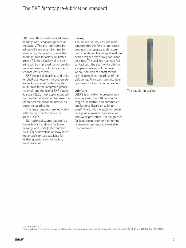
SKF now offers pre-lubricated linearbearings as a standard greased atthe factory. The pre-lubricated be-arings will save assembly time by eliminating the need to grease thebearings. Due to factory calibratedgrease fill, the reliability of the be-aring will be improved. Using pre-lu-bricated bearings will reduce main-tenance costs as well.
SKF linear ball bearings and unitsfor shaft diameter 6 mm and greaterare factory pre-lubricated1) by de-fault2). Due to the integrated greasereservoir and the use of SKF double-lip seals (2LS), most applications willnot require relubrication because thetheoretical relubrication interval ex-ceeds the bearing life.
The linear bearings are lubricatedwith the high-performance SKFgrease LGEP2.
Our technical support as well asthe technical handbook for linear bearings and units (order number6402 EN or download at www.linear-motion.skf.com) are available forfurther questions on the factory pre-lubrication.
Sea���gThe double-lip seal ensures main-tenance-free life for pre-lubricatedbearings that operate under stan-dard conditions. The integral seal hasbeen designed specifically for linearbearings. The seal lips maintain fullcontact with the shaft while offeringa superior sealing solution evenwhen used with the shaft for theself-aligning linear bearings of theLBC series. The seals have also beenoptimized for low friction operation.
L�b��ca��LGEP2 is an extreme pressure be-aring grease from SKF for a widerange of industrial and automotiveapplications. Based on a lithium soap/mineral oil, the additives provi-de a good corrosion resistance andanti-wear protection. Special greasesfor food, clean room or high tempe-rature environments are availableupon request.
1) as from July 20072) linear ball bearings without factory pre-lubrication and preservative only can be ordered by using the suffix “/VT808”, e.g. LBCR 20 A-2LS/VT808
The double-lip sealing
7
4
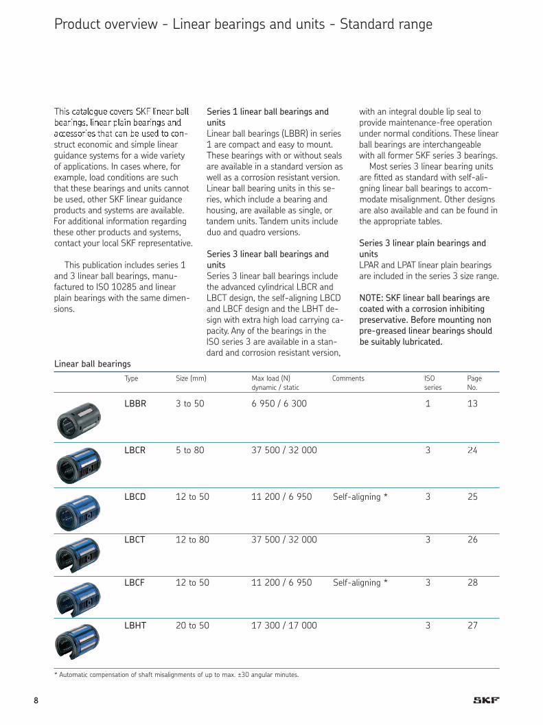
Th�� ����� � ������ !" �#��� $�$����#��% �#��� &��# $����#�� �#'����������� (� ��# $� ��' � ��#-struct economic and simple linearguidance systems for a wide varietyof applications. In cases where, forexample, load conditions are suchthat these bearings and units cannotbe used, other SKF linear guidanceproducts and systems are available.For additional information regardingthese other products and systems,contact your local SKF representative.
This publication includes series 1and 3 linear ball bearings, manu-factured to ISO 10285 and linearplain bearings with the same dimen-sions.
with an integral double lip seal toprovide maintenance-free operationunder normal conditions. These linearball bearings are interchangeablewith all former SKF series 3 bearings.
Most series 3 linear bearing unitsare fitted as standard with self-ali-gning linear ball bearings to accom-modate misalignment. Other designsare also available and can be found inthe appropriate tables.
Series 3 linear plain bearings and
units
LPAR and LPAT linear plain bearingsare included in the series 3 size range.
NOTE: SKF linear ball bearings are
coated with a corrosion inhibiting
preservative. Before mounting non
pre-greased linear bearings should
be suitably lubricated.
Series 1 linear ball bearings and
units
Linear ball bearings (LBBR) in series1 are compact and easy to mount.These bearings with or without sealsare available in a standard version aswell as a corrosion resistant version.Linear ball bearing units in this se-ries, which include a bearing andhousing, are available as single, ortandem units. Tandem units includeduo and quadro versions.
Series 3 linear ball bearings and
units
Series 3 linear ball bearings includethe advanced cylindrical LBCR andLBCT design, the self-aligning LBCDand LBCF design and the LBHT de-sign with extra high load carrying ca-pacity. Any of the bearings in the ISO series 3 are available in a stan-dard and corrosion resistant version,
Type Size (mm) Max load (N) Comments ISO Pagedynamic / static series No.
LBBR 3 to 50 6 950 / 6 300 1 9
LBCR 5 to 80 37 500 / 32 000 3 20
LBCD 12 to 50 11 200 / 6 950 Self-aligning * 3 21
LBCT 12 to 80 37 500 / 32 000 3 22
LBCF 12 to 50 11 200 / 6 950 Self-aligning * 3 24
LBHT 20 to 50 17 300 / 17 000 3 23
Linear ball bearings
* Automatic compensation of shaft misalignments of up to max. ?30 angular minutes.
Product overview - Linear bearings and units - Standard range
13
2)
25
26
28
27
8
5
*+,-./0 ,13+1435 - Linear bearings and units - Standard range
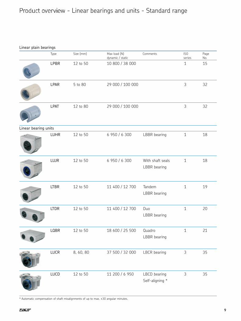
LPBR 12 to 50 10 800 / 38 000 1 11
LPAR 5 to 80 29 000 / 100 000 3 28
LPAT 12 to 80 29 000 / 100 000 3 28
Linear bearing units
LUHR 12 to 50 6 950 / 6 300 LBBR bearing 1 14
LUJR 12 to 50 6 950 / 6 300 With shaft seals 1 14
LBBR bearing
LTBR 12 to 50 11 400 / 12 700 Tandem 1 15
LBBR bearing
LTDR 12 to 50 11 400 / 12 700 Duo 1 16
LBBR bearing
LQBR 12 to 50 18 600 / 25 500 Quadro 1 17
LBBR bearing
LUCR 8, 60, 80 37 500 / 32 000 LBCR bearing 3 31
LUCD 12 to 50 11 200 / 6 950 LBCD bearing 3 31
Self-aligning *
Type Size (mm) Max load (N) Comments ISO Pagedynamic / static series No.
Linear plain bearings
* Automatic compensation of shaft misalignments of up to max. ?30 angular minutes.
15
32
32
18
18
19
20
21
35
35
9

Product overview - Linear bearings and units - Standard range
LUCS 8, 60, 80 37 500 / 32 000 LBCR bearing 3 32
LUCE 12 to 50 11 200 / 6 950 LBCD bearing 3 32
Self-aligning *
LUCT 60, 80 37 500 / 32 000 LBCT bearing 3 33
LUCF 12 to 50 11 200 / 6 950 LBCF bearing 3 33
Self-aligning *
LUCT … BH 20 to 50 17 300 / 17 000 LBHT bearing 3 34
LUND 12 to 50 11 200 / 6 950 LBCD bearing 3 35
Self-aligning *
LUNE 12 to 50 11 200 / 6 950 LBCD bearing 3 36
Self-aligning *
LUNF 12 to 50 11 200 / 6 950 LBCF bearing 3 37
Self-aligning *
LVCR 12 to 80 37 500 / 32 000 LBCR bearing 3 38
LTCD 12 to 50 18 300 / 14 000 Tandem 3 39
LBCD bearing
Self-aligning *
LTCF 12 to 50 18 300 / 14 000 Tandem 3 40
LBCF bearing
Self-aligning *
Type Size (mm) Max load (N) Comments ISO Pagedynamic / static series No.
Linear bearing units
* Automatic compensation of shaft misalignments of up to max. ?30 angular minutes.
67
67
68
68
38
39
40
41
42
43
44
10
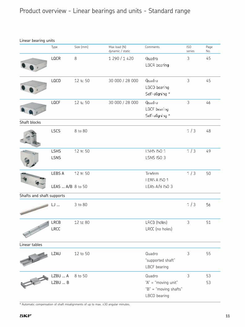
LQCR 8 1 290 : ; <20 =>?@AB 3 <;
CDEF GH?AIJK
LQCD ;2 LB 50 30 000 : 28 000 =>?@AB 3 <;
CDEM GH?AIJK
NHOP-?OIKJIJK *
LQCF ;2 LB 50 30 000 : 28 000 =>?@AB 3 <2
CDEF GH?AIJK
NHOP-?OIKJIJK *
Shaft blocks
LSCS 8 LB 80 ; : 3 <<
LSHS ;2 LB 50 CNHN INO ; ; : 3 <5
LSNS CNNN INO 3
LEBS A ;2 LB 50 T?J@Hm ; : 3 <6
CEDN A INO ;
LEAS … A/B 8 LB 50 CEAN A:D INO 3
Shafts and shaft supports
LJ … 3 LB 80 ; : 3 53
LRCB ;2 LB 80 CFED (hBOHs) 3 <7
LRCC CREE (no holes)
Linear tables
LZAU 12 to 50 Quadro 3 51
“supported shaft”
LBCF bearing
LZBU … A 8 to 50 Quadro 3 49
LZBU … B “A” = “moving unit” 50
“B” = “moving shafts”
LBCD bearing
Product overview - Linear bearings and units - Standard range
Type Size (mm) Max load (N) Comments ISO Pagedynamic / static series No.
Linear bearing units
* Automatic compensation of shaft misalignments of up to max. ?30 angular minutes.
45
45
QR
48
49
50
SR
51
55
53
53
11
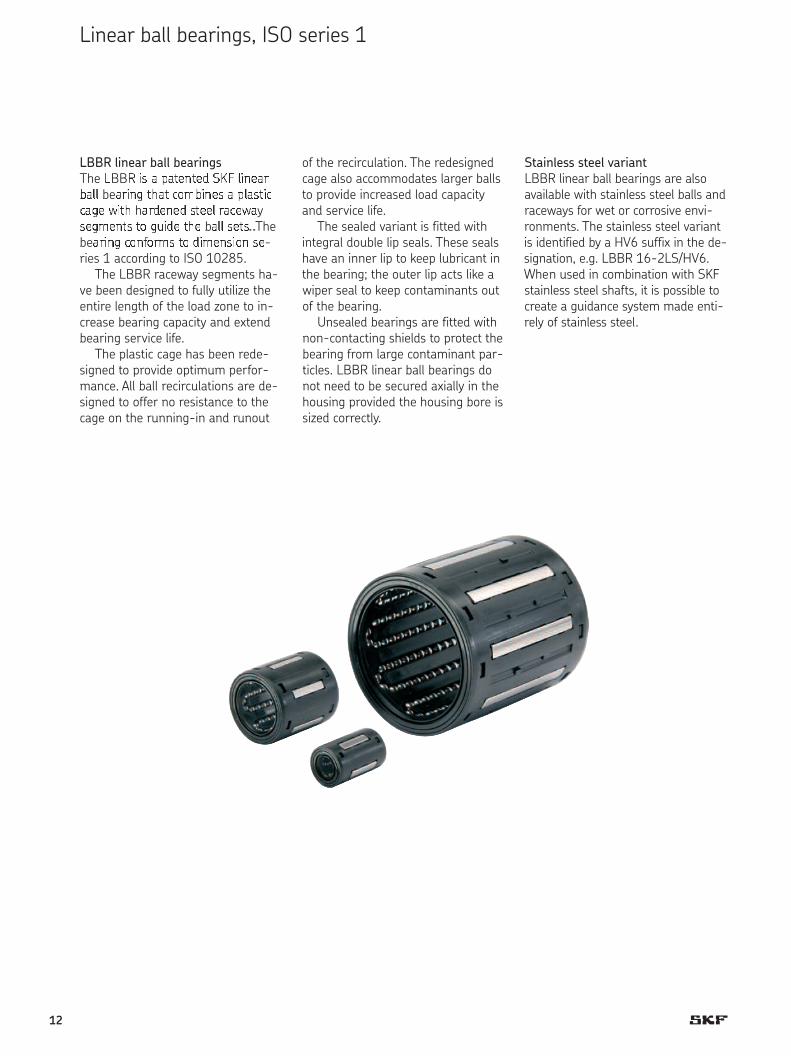
LBBR linear ball bearingsThe TBBU VW X YXZ[\Z[] ^_` aV\[XbcXaa beXbV\d ZeXZ fghcV\[W X YaXWZVffXd[ iVZe hXb][\[] WZ[[a bXf[iXyW[dh[\ZW Zg djV][ Ze[ bXaa W[ZWk ThebeXbV\d fg\lgbhW Zg ]Vh[\WVg\ W[-ries 1 according to ISO 10285.
The LBBR raceway segments ha-ve been designed to fully utilize theentire length of the load zone to in-crease bearing capacity and extendbearing service life.
The plastic cage has been rede-signed to provide optimum perfor-mance. All ball recirculations are de-signed to offer no resistance to thecage on the running-in and runout
Stainless steel variantLBBR linear ball bearings are alsoavailable with stainless steel balls andraceways for wet or corrosive envi-ronments. The stainless steel variantis identified by a HV6 suffix in the de-signation, e.g. LBBR 16-2LS/HV6.When used in combination with SKFstainless steel shafts, it is possible tocreate a guidance system made enti-rely of stainless steel.
of the recirculation. The redesignedcage also accommodates larger ballsto provide increased load capacityand service life.
The sealed variant is fitted withintegral double lip seals. These sealshave an inner lip to keep lubricant inthe bearing; the outer lip acts like awiper seal to keep contaminants outof the bearing.
Unsealed bearings are fitted withnon-contacting shields to protect thebearing from large contaminant par-ticles. LBBR linear ball bearings donot need to be secured axially in thehousing provided the housing bore issized correctly.
Linear ball bearings, ISO series 1
12

Linear ball bearings – LBBR - with raceway plates
C
DFW
mnnopqrs tuvwxy xqz {y|x{
9
1) Width 22 does not correspond to series 1 in ISO standard 10285.2) not factory pre-lubricated
Dimensions No. of Basic load Mass Designations
ball rows ratings
Linear ball bearings stainless steel
dyn. stat. standard with 2 double standard with 2 double
Fw D C C CO design lip seals design lip seals
mm — N kg —
3 7 10 4 60 44 0,0007 LBBR 3 2) LBBR 3 -2 LS2) LBBR 3 /HV6 2) LBBR 3 -2 LS/HV6 2)
4 8 12 4 75 60 0,001 LBBR 4 2) LBBR 4 -2 LS2) LBBR 4 /HV6 2) LBBR 4 -2 LS/HV6 2)
5 10 15 4 170 129 0,002 LBBR 5 2) LBBR 5 -2 LS2) LBBR 5 /HV6 2) LBBR 5 -2 LS/HV6 2)
6 12 221) 4 335 270 0,006 LBBR 6 A LBBR 6 A-2 LS LBBR 6 A /HV6 LBBR 6 A-2 LS/HV6
8 15 24 4 490 355 0,007 LBBR 8 LBBR 8 -2 LS LBBR 8 /HV6 LBBR 8 -2 LS/HV6
1 0 17 26 5 585 415 0,011 LBBR 1 0 LBBR 1 0 -2 LS LBBR 1 0 /HV6 LBBR 1 0 -2 LS/HV6
1 2 19 28 5 695 510 0,012 LBBR 1 2 LBBR 1 2 -2 LS LBBR 1 2 /HV6 LBBR 1 2 -2 LS/HV6
1 4 21 28 5 710 530 0,013 LBBR 1 4 LBBR 1 4 -2 LS LBBR 1 4 /HV6 LBBR 1 4 -2 LS/HV6
1 6 24 30 5 930 630 0,018 LBBR 1 6 LBBR 1 6 -2 LS LBBR 1 6 /HV6 LBBR 1 6 -2 LS/HV6
2 0 28 30 6 1 160 800 0,021 LBBR 2 0 LBBR 2 0 -2 LS LBBR 2 0 /HV6 LBBR 2 0 -2 LS/HV6
2 5 35 40 7 2 120 1 560 0,047 LBBR 2 5 LBBR 2 5 -2 LS LBBR 2 5 /HV6 LBBR 2 5 -2 LS/HV6
3 0 40 50 8 3 150 2 700 0,070 LBBR 3 0 LBBR 3 0 -2 LS LBBR 3 0 /HV6 LBBR 3 0 -2 LS/HV6
4 0 52 60 8 5 500 4 500 0,130 LBBR 4 0 LBBR 4 0 -2 LS LBBR 4 0 /HV6 LBBR 4 0 -2 LS/HV6
5 0 62 70 9 6 950 6 300 0,18 LBBR 5 0 LBBR 5 0 -2 LS LBBR 5 0 /HV6 LBBR 5 0 -2 LS/HV6
Appropriate special seals
Dimensions Designations
Fw D B1
mm —
25 35 4 SP-25x35x4
30 40 4 SP-30x40x4
40 52 5 SP-40x52x5
50 62 5 SP-50x62x5
Appropriate special seals
Dimensions Designations
Fw D B1
mm —
6 12 2 SP-6x12x2
8 15 3 SP-8x15x3
10 17 3 SP-10x17x3
12 19 3 SP-12x19x3
14 21 3 SP-14x21x3
16 24 3 SP-16x24x3
20 28 4 SP-20x28x4
Accessories for LBBR (shaft seals)
SP
The outside diameter tolerance of the linear ball bearings is such that no additional axial fixation is required when thebearings are fitted into a bore with a tolerance of J7 or J6.
}~
B 1
F wD
13

LPBR �inear plain bearings, whichhave the same dimensions as LBBRlinear ball bearings, are made out ofPAS-LX (Copolymeres Polyoxyme-thylen) with a special polyethylene toprovide smooth, stick-slip-free ope-ration. These linear plain bearingsare self lubricating under normalconditions and require minimalmaintenance. They have a high staticload carrying capacity and are resis-tant to shock loads.
SKF recommends a light coatingof lubricant during installation to im-prove the performance during therunning-in period even if the be-arings are to be used “lubricant-free”.
LPBR linear plain bearings are inten-ded for applications where there areheavy shock loads and/or vibrationsor high accelerations and speedswhen the bearing is unloaded. Underthese operating conditions linearplain bearings provide longer servicelife than linear ball bearings. Howe-ver, increased friction must be ex-pected.
Linear plain bearings, ISO series 1
14
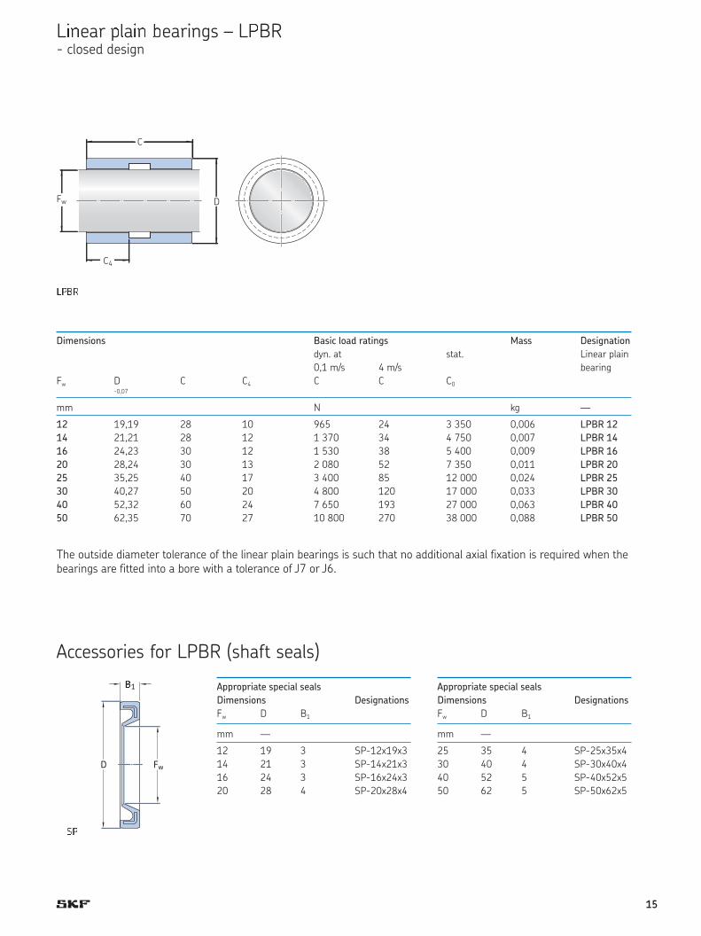
L��ear ��a�� �earings – L�BR- closed design
LPBR
Dimensions Basic load ratings Mass Designation
dyn. at stat. Linear plain
0,1 m/s 4 m/s bearing
Fw D C C4 C C C0-0,07
mm N kg —
12 19,19 28 10 965 24 3 350 0,006 LPBR 12
14 21,21 28 12 1 370 34 4 750 0,007 LPBR 14
16 24,23 30 12 1 530 38 5 400 0,009 LPBR 16
20 28,24 30 13 2 080 52 7 350 0,011 LPBR 20
25 35,25 40 17 3 400 85 12 000 0,024 LPBR 25
30 40,27 50 20 4 800 120 17 000 0,033 LPBR 30
40 52,32 60 24 7 650 193 27 000 0,063 LPBR 40
50 62,35 70 27 10 800 270 38 000 0,088 LPBR 50
The outside diameter tolerance of the linear plain bearings is such that no additional axial fixation is required when thebearings are fitted into a bore with a tolerance of J7 or J6.
Appropriate special seals
Dimensions Designations
Fw D B1
mm —
25 35 4 SP-25x35x4
30 40 4 SP-30x40x4
40 52 5 SP-40x52x5
50 62 5 SP-50x62x5
Appropriate special seals
Dimensions Designations
Fw D B1
mm —
12 19 3 SP-12x19x3
14 21 3 SP-14x21x3
16 24 3 SP-16x24x3
20 28 4 SP-20x28x4
Accessories for LPBR (shaft seals)
SP
����
Fw D
C
C4
�1
FwD
��
15
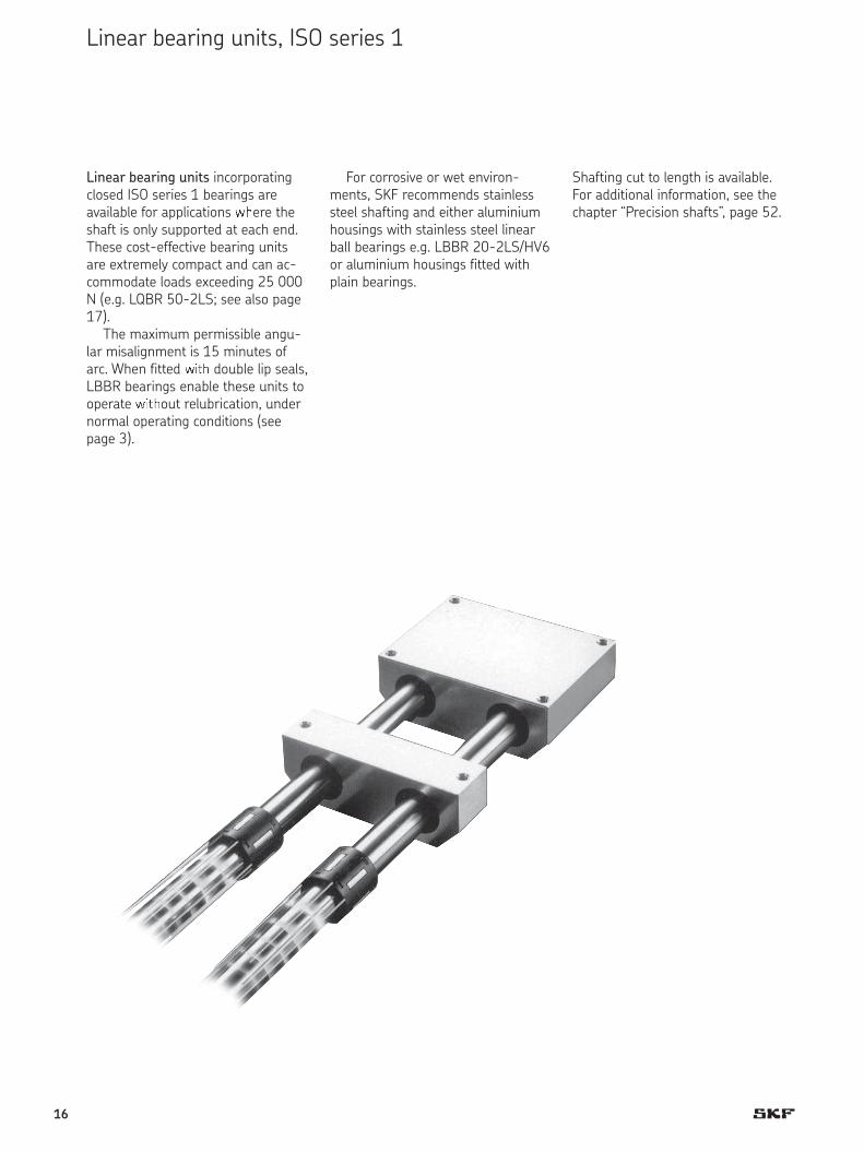
Linear bearing units incorporatingclosed ISO series 1 bearings areavailable for applications ��ere theshaft is only supported at each end.These cost-effective bearing unitsare extremely compact and can ac-commodate loads exceeding 2 5 0 0 0N (e.g. LQBR 5 0 -2 LS; see also page17 ).
The maximum permissible angu-lar misalignment is 15 minutes ofarc. When fitted ���� double lip seals,LBBR bearings enable these units tooperate ����out relubrication, undernormal operating conditions (see page 3 ).
Shafting cut to length is available.For additional information, see thechapter “Precision shafts”, page 52.
For corrosive or wet environ-ments, SKF recommends stainlesssteel shafting and either aluminiumhousings with stainless steel linearball bearings e.g. LBBR 20-2LS/HV6or aluminium housings fitted withplain bearings.
Linear bearing units, ISO series 1
16

LUHR/LUJR linear bearing unitsconsist of a housing of extruded alu-minium and the compact LBBR line-ar ball bearing or the LPBR linearplain bearing of similar dimensions.
The LUHR design, for shaft dia-meters from 12 to 50 mm, is availa-ble fitted as standard with LBBR li-near ball bearings with or withoutintegrated seals or with LPBR linearplain bearings (designation LUHR …PB).
For highly contaminated environ-ments, extended LUJR linear bearingunits are available. These incorporateLBBR linear ball bearings and two SP-type shaft seals. LUHR and LUJRlinear bearing units cannot be relu-bricated.
LQBR quadro linear bearing units –contain four (4) LBBR linear ball be-arings within a sealed aluminiumhousing. The duo configuration andthe space between the bearings per-mit the fitting of a linear drive. Duoand quadro linear bearing units ba-sed on LBBR linear ball bearings canbe used to make compact, simple ta-ble configurations. For suitable shaftblocks (LEBS), see page 46.
LTBR tandem linear bearing unitsconsist of a one-piece extruded alu-minium housing and two LBBR line-ar ball bearings mounted one behindthe other. These units are fitted withsealed bearings as standard andcannot be relubricated. They are particularly suitable for tables or sli-des of any width.
LTDR duo linear bearing units arecharacterised by an aluminium hou-sing that contains two LBBR-2LS li-near ball bearings in parallel. Thespace between the two bearings andthe duo configuration permits easyfitting of a linear drive.
LTDR LQBR
LUJR LUHR LTBR
17

Linear bearing units – LUHR/LUJR- with closed housing and LBBR linear ball bearings
Dimensions Basic load Mass Designations
ratings
Design Linear bearing unit
dyn. stat. LUHR LUJR without with with
Fw A A1 C1 Da H H1 H2 H3 L J N1) N11) C C0 seal double lip shaft
±0,01 seal seals
mm — N kg
12 28 35 34 19 17 33 16 11 40 29 4,3 M 5 695 510 0,08 0,10 LUHR 12 LUHR 12-2LS LUJR 12
16 30 37 36 24 19 38 18 11 45 34 4,3 M 5 930 630 0,10 0,12 LUHR 16 LUHR 16-2LS LUJR 16
20 30 39 38 28 23 45 22 13 53 40 5,3 M 6 1 160 800 0,14 0,18 LUHR 20 LUHR 20-2LS LUJR 20
25 40 49 48 35 27 54 26 18 62 48 6,6 M 8 2 120 1 560 0,25 0,30 LUHR 25 LUHR 25-2LS LUJR 25
30 50 59 58 40 30 60 29 18 67 53 6,6 M 8 3 150 2 700 0,37 0,44 LUHR 30 LUHR 30-2LS LUJR 30
40 60 71 70 52 39 76 38 22 87 69 8,4 M 10 5 500 4 500 0,74 0,86 LUHR 40 LUHR 40-2LS LUJR 40
50 70 81 80 62 47 92 46 26 103 82 10,5 M 12 6 950 6 300 1,19 1,37 LUHR 50 LUHR 50-2LS LUJR 50
Da
A
Fw
LUHR With double lip seals
LUJR With shaft seals
1) For screws with internal hexagon to DIN 912 / ISO 4762.
For suitable shaft blocks for these bearing units, designation LSHS, see page 45.
Linear bearing units of the LUHR design are also available fitted with LPBR linear plain bearings. Designations: e. g. LUHR 20 PB.
A1
C1
�UHRWith double l�� ����
�UJR���� ����� �����
A
D�
A1
C1
�w
H3H2
H1
N
H
L
J
N1N1
18
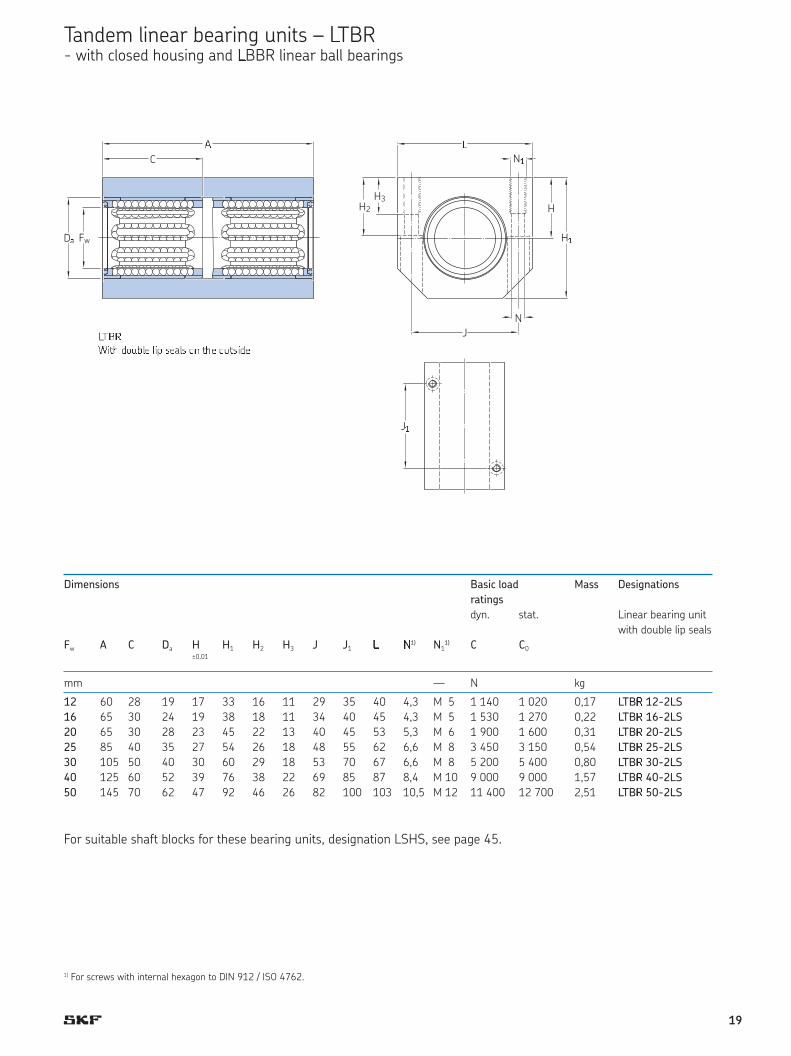
Tandem linear bearing units – �TBR - with closed housing and �BBR linear ball bearings
Dimensions Basic load Mass Designations
ratings
dyn. stat. �inear bearing unit
with double lip seals
Fw A C Da H H1 H2 H3 J J1 ¡ 1 ) N11 ) C C 0
±0 ,0 1
¢¢ — N kg
1 2 6 0 28 19 17 33 16 11 29 35 4 0 4,3 M 5 1 140 1 020 0,17 TBR 12-2LS
16 65 30 24 19 38 18 11 34 40 45 4,3 M 5 1 530 1 270 0,22 LTBR 16-2LS
20 65 30 28 23 45 22 13 40 45 53 5,3 M 6 1 900 1 600 0,31 LTB£ 20-2 S2 5 85 40 35 27 54 26 18 48 55 62 6,6 M 8 3 450 3 150 0,54 TB£ 2 5 -2 S30 105 50 40 30 60 29 18 53 70 67 6,6 M 8 5 200 5 400 0,80 TB£ 30-2 S
40 125 60 52 39 76 38 22 69 85 87 8,4 M 10 9 000 9 000 1,57 ¤B£ 40-2 S
50 145 70 62 47 92 46 26 82 100 103 10,5 M 12 11 400 12 700 2,51 ¤B£ 50-2LS
C
FwDa
A
LTBRWith double lip seals on the outside
1) For screws with internal hexagon to DIN 912 / ISO 4762.
For suitable shaft blocks for these bearing units, designation LSHS, see page 45.
J¥
C
D¦ Fw
§ ¨
H3
H¥
H
N
J
H2
N¥N¥
Dimensions Basic load Mass Designations
ratings
dyn. stat. Linear bearing unit
with double lip seals
Fw A C Da H H1 H2 H3 J J1 ¡1) N11) C C0
±0,01
mm — N kg
12 60 28 19 17 33 16 11 29 35 40 4,3 M 5 1 140 1 020 0,17 LTB£ 12-2LS
16 65 30 24 19 38 18 11 34 40 45 4,3 M 5 1 530 1 270 0,22 LTB£ 16-2LS
20 65 30 28 23 45 22 13 40 45 53 5,3 M 6 1 900 1 600 0,31 LTB£ 20-2LS
25 85 40 35 27 54 26 18 48 55 62 6,6 M 8 3 450 3 150 0,54 LTB£ 25-2LS
30 105 50 40 30 60 29 18 53 70 67 6,6 M 8 5 200 5 400 0,80 LTB£ 30-2LS
40 125 60 52 39 76 38 22 69 85 87 8,4 M 10 9 000 9 000 1,57 LTB£ 40-2LS
50 145 70 62 47 92 46 26 82 100 103 10,5 M 12 11 400 12 700 2,51 LTB£ 50-2LS
For suitable shaft blocks for these bearing units, designation LSHS, see page 45.
L©ª«¬®¯ °±²³´µ ´¶ ·µa´· ±¸ ®¯µ ±²®· °µ
19
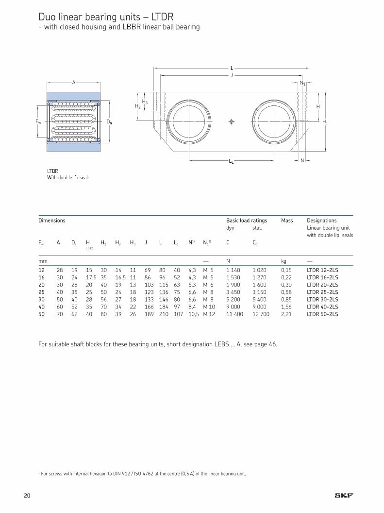
Duo linear bearing units – LTDR - with closed housing and LBBR linear ball bearing
Dimensions Basic load ratings Mass Designations
dyn stat. Linear bearing unit
with double lip seals
Fw A Da H H1 H2 H3 J L L1 N1) N11) C C0
±0,01
mm — N kg —
12 28 19 15 30 14 11 69 80 40 4,3 M 5 1 140 1 020 0,15 LTDR 12-2LS
16 30 24 17,5 35 16,5 11 86 96 52 4,3 M 5 1 530 1 270 0,22 LTDR 16-2LS
20 30 28 20 40 19 13 103 115 63 5,3 M 6 1 900 1 600 0,30 LTDR 20-2LS
25 40 35 25 50 24 18 123 136 75 6,6 M 8 3 450 3 150 0,58 LTDR 25-2LS
30 50 40 28 56 27 18 133 146 80 6,6 M 8 5 200 5 400 0,85 LTDR 30-2LS
40 60 52 35 70 34 22 166 184 97 8,4 M 10 9 000 9 000 1,56 LTDR 40-2LS
50 70 62 40 80 39 26 189 210 107 10,5 M 12 11 400 12 700 2,21 LTDR 50-2LS
Fw Da
A
LTDRWith double lip seals
1) For screws with internal hexagon to DIN 912 / ISO 4762 at the centre (0,5 A) of the linear bearing unit.
For suitable shaft blocks for these bearing units, short designation LEBS … A, see page 46.
A
Fw D¹
H3H2
º
N»
H
H»
º» N
J
L¼½¾¿ÀÁ ÃÄÅÆÇÈ ÇÀÉ ÊÈËÇÊ
20

Dimensions Basic load ratings Mass Designations
dyn. stat. Linear ball
baring unit
Fw A C Da H H1 H2 H3 J J1 L L1 N1) N11) C C0 with double
±0,01 lip seals
mm — N kg —
12 70 28 19 15 30 14 11 69 59 80 40 4,3 M 5 1 860 2 040 0,38 LQBR 12-2LS
16 80 30 24 17,5 35 16,5 11 86 70 96 52 4,3 M 5 2 500 2 550 0,57 LQBR 16-2LS
20 85 30 28 20 40 19 13 103 73 115 63 5,3 M 6 3 100 3 200 0,82 LQBR 20-2LS
25 100 40 35 25 50 24 18 123 87 136 75 6,6 M 8 5 600 6 300 1,43 LQBR 25-2LS
30 130 50 40 28 56 27 18 133 117 146 80 6,6 M 8 8 500 10 800 2,15 LQBR 30-2LS
40 150 60 52 35 70 34 22 166 132 184 97 8,4 M 10 14 600 18 000 3,83 LQBR 40-2LS
50 175 70 62 40 80 39 26 189 154 210 107 10,5 M 12 18 600 25 500 5,40 LQBR 50-2LS
For suitable shaft blocks for these bearing units, designation LEBS … A, see page 46.
N
LÌÍÎWith double lip seals on the outside
FwDa
C
A
L
H3H2
N1
H
H1
L1
J1
J
J
Quadro linear bearing units – LQBR - with closed housing and LBBR linear ball bearing
1) For 4 screws with internal hexagon to DIN 912 / ISO 4762.
21

LBÏ linear ÐÑÒÒ Ðearings, ÓÔÕÖ ÕÖ×ÔrÖÔgÖ ØÙÚd carrying capacity, are avai-lable for shaft diameters from 5 to80 mm. As with all SKF linear ballbearings, they are available with achoice of seals or shields. 5 and 8mm LBC linear ball bearings that arefull contained within their housings,are self-retaining so that no additio-nal axial location is required undernormal operating conditions.
All LBC linear ball bearings aregenerally designed for grease lubri-cation. Sizes from 12-80 mm featu-re cages with a through-bored radialhole to accommodate a grease fit-ting, which provides longitudinal andaxial fixation. Grease may be applieddirectly to the shaft or bearing viathis hole. For the relubrication ofLBHT linear ball bearings the hou-sing must be provided with a greasedistribution channel in the bore orhousing. The grease is then forcedonto the raceway between the loadcarrying plates. Information on thelocation of these attachment holes and grease fittings is shown onpages 25 and 26.
LBCR linear ball bearings, with theiroptimised raceway segments andposition for maximum load carryingcapacity, can be mounted in closedas well as adjustable housings. Whenthese bearings are mounted in a clo-sed housing, the tolerance of the ins-cribed diameter of the ball set andhence the operating clearance is de-termined by the tolerance of thehousing bore. When mounted inslotted housings the linear guidescan be adjusted to provide eitheroperating clearance or preload de-pending on the needs of the applica-tion. LBCR linear ball bearings mustbe located in the axial direction, forexample via the grease fitting or a fixation pin.
Stainless steel variant
LBC linear ball bearings are alsoavailable with stainless steel ballsand raceways for wet or corrosiveenvironments. The stainless steel va-riant is identified by adding a HV6suffix to the designation e.g. LBCR16-2LS/HV6. When used in combi-nation with SKF stainless steelshafts, it is possible to create a gui-dance system made entirely of stain-less steel.
LBCR linear ball bearings consist ofa cage and raceway segments toguide the balls and either seals orshields. By virtue of their exceptio-nally long track length and the ma-chined raceway osculation, they areable to accommodate heavy loads.
Linear ball bearings, ISO series 3
LBHT
LBCF
LBCT
LBCD
LBCR
22

LÛÜD linear ball bearings ÝÞe Ý vÝÞß-ant of the LBCR design. The primaryfeature of this bearing is its self-ali-gning capability that accommodatestilting of the whole bearing throughan angle of ±30 minutes of arc. Thistilting feature compensates for misa-lignment, which may be caused byinaccuracies in fitting or manufactu-ring (housing bore diameter), or bysignificant bending of an unsuppor-ted shaft. The self-aligning featurecannot, however, compensate for twonon-parallel shafts in an assembly.The cage, seals and shields havebeen optimized to accommodate theself aligning feature so that the be-aring and especially the shields orseals remain concentric with theshaft.
All other characteristics of theLBCR linear ball bearings are alsovalid for the self-aligning LBCD de-sign. LBCD linear ball bearings mustalways be firmly fixed in the axial direction.
LBCF linear ball bearings are a self-aligning version of the LBCT design.These bearings are available in sizesranging from 12 to 50 mm. LBCF li-near ball bearings must always be fixed to prevent axial and turningmovements.
LBCT and LBHT linear ball bearings
are used in applications where seve-ral shaft supports, or a continuousshaft support is needed to preventshaft bending. Due to the open de-sign of the LBCT bearing, one race-way segment is eliminated. However,this does not have a significant effecton its load carrying capacity. The ra-ceway segments of the LBHT howe-ver, have been optimized so that ithas the same number of racewaysegments as a closed design bearing.
Both the LBCT and the LBHT areavailable for shaft diameters rangingfrom 20 to 50 mm. Unlike otheropen design linear ball bearings, the-se bearings feature a shoulder in thecage on each side of the openingwhich acts like a gap-type seal. Opendesigned LBCT/LBHT linear ball be-arings must always be fixed to pre-vent axial and turning movements.
23
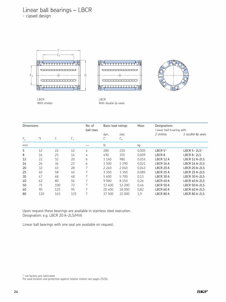
àáâãar baää åãarings – àBæR - cçèséd désign
Dimensions No. of Basic load ratings Mass Designations
ball rows êëìíar baîî ïíaring with
dyn. stat. 2 shiíîds 2 douïîí îëð síaîsñw ò ó ó3 ó ó0
mm — N kg
5 1 2 22 12 4 280 210 0,005 LBCR 51) LBCR 5- 2LS1)
8 16 25 14 4 490 355 0,009 LBCR 8 LBCR 8- 2LS
12 22 32 20 6 1 160 980 0,016 LBCR 12 A LBCR 12 A-2LS
16 26 36 22 6 1 500 1 290 0,021 LBCR 16 A LBCR 16 A-2LS
20 32 45 28 7 2 240 2 040 0,043 LBCR 20 A LBCR 20 A-2LS
25 40 58 40 7 3 350 3 350 0,085 LBCR 25 A LBCR 25 A-2LS
30 47 68 48 7 5 600 5 700 0,13 LBCR 30 A LBCR 30 A-2LS
40 62 80 56 7 9 000 8 150 0,26 LBCR 40 A LBCR 40 A-2LS
50 75 100 72 7 13 400 12 200 0,46 LBCR 50 A LBCR 50 A-2LS
60 90 125 95 7 20 400 18 000 0,82 LBCR 60 A LBCR 60 A-2LS
80 120 165 125 7 37 500 32 000 1,9 LBCR 80 A LBCR 80 A-2LS
LBCRWith shields
1) not factory pre-lubricatedFor axial location and protection against relative motion see pages 25/26.
Upon request these bearings are available in stainless steel execution.Designation: e.g. LBCR 20 A-2LS/HV6
Linear ball bearings with one seal are available on request.
LBCR With double lip seals
DFw
C3
C
LBCRWith shields
LBCRWith double l ip seals
24

Dimensions No. of Basic load ratings Mass Designations
ball rows . ôõöear ÷all ÷earõögs øõùúûün. stat 2 súõelûs 2 ûoý÷þe þõÿ seals
� D C C3 C C0
mm — N kg
12 22 32 20 6 1 080 815 0,015 LBCD 12 A LBCD 12 A-2LS
16 26 36 22 6 1 320 865 0,020 LBCD 16 A LBCD 16 A-2LS
20 32 45 28 7 2 000 1 370 0,042 LBCD 20 A LBCD 20 A-2LS
25 40 58 40 7 2 900 2 040 0,083 LBCD 25 A LBCD 25 A-2LS
30 47 68 48 7 4 650 3 250 0,13 LBCD 30 A LBCD 30 A-2LS
40 62 80 56 7 7 800 5 200 0,26 LBCD 40 A LBCD 40 A-2LS
50 75 100 72 7 11 200 6 950 0,44 LBCD 50 A LBCD 50 A-2LS
Upon request these bearings are available in stainless steel execution.Designation: e.g. LBCD 20 A-2LS/HV6
Linear ball bearings with one seal are available on request.
Linear ball bearings – LBCD - self aligning and closed design
LBCDWith shields
LBCDWith double lip seals
For axial location and protection against relative motion see pages 25/26. Retaining rings according to DIN 471.
DFw
C3
C
30
30
L���With double lip seals
L���With shields
25
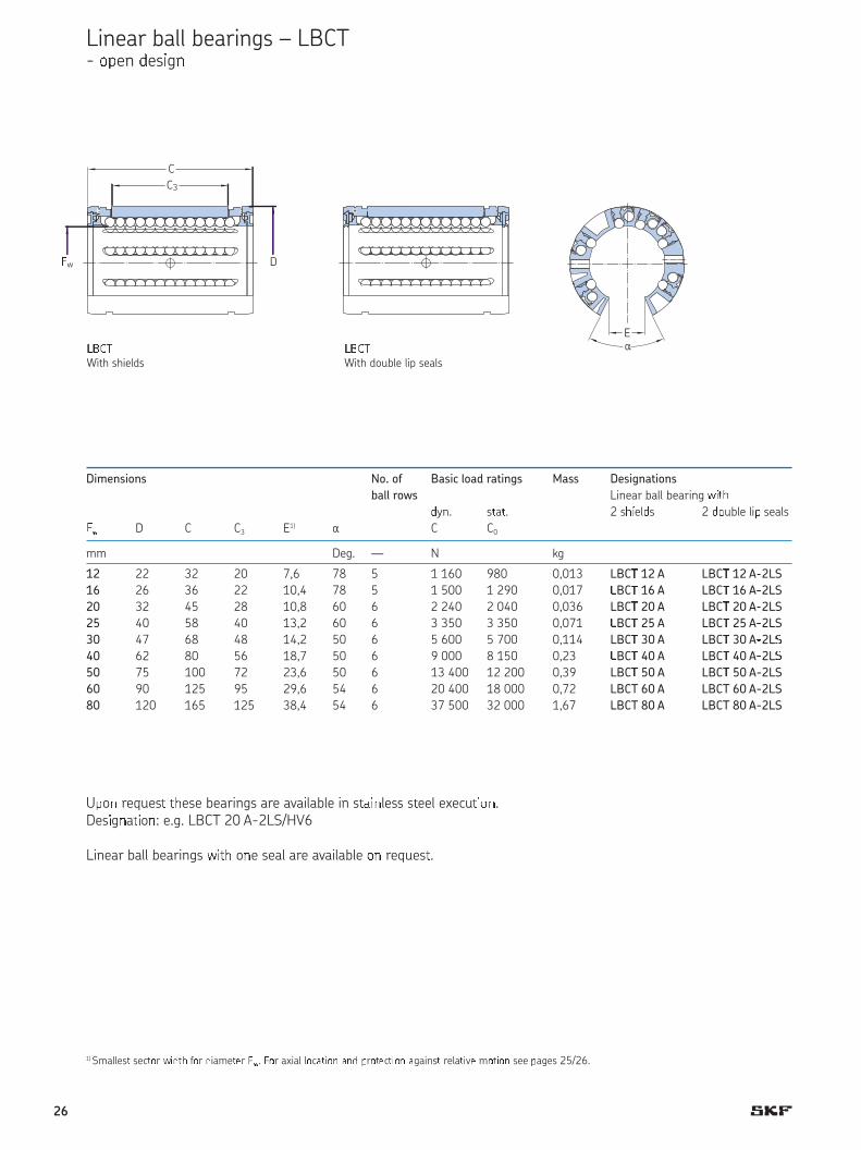
Linear ball bearings – LBCT - � en �es�g�
Dimensions No. of Basic load ratings Mass Designations
ball rows Linear ball bearing ����yn. sa. 2 s��el�s 2 ��uble li� seals
�� D C C3 E1)a C C0
mm Deg. — N kg
12 22 32 20 7,6 78 5 1 160 980 0,013 LBC� 12 A LBC� 12 A�2LS
16 26 36 22 10,4 78 5 1 500 1 290 0,017 �BC� 16 A LBC� 16 A�2LS
20 32 45 28 10,8 60 6 2 240 2 040 0,036 LBC� 20 A LBC� 20 A�2LS
25 40 58 40 13,2 60 6 3 350 3 350 0,071 �BC� 25 A LBC� 25 A�2LS
30 47 68 48 14,2 50 6 5 600 5 700 0,114 LBC� 30 A LBC� 30 A�2L�4 0 62 80 56 18,7 50 6 9 000 8 150 0,23 �BC� 40 A LBC� 40 A�2L�5 0 75 100 72 23,6 50 6 13 400 12 200 0,39 LBC� 50 A LBC� 50 A-2LS
60 90 125 95 29,6 54 6 20 400 18 000 0,72 LBCT 60 A LBCT 60 A-2LS
80 120 165 125 38,4 54 6 37 500 32 000 1,67 LBCT 80 A LBCT 80 A-2LS
LBCTWi�� s��el�s
LBCT Wi�� ��uble li� seals
1) Smalles� sec��r � !�" f�r !iame�#r $�. $�r axial l�c%� �& %&! 'r��#c� �& %gains� rela� v# m�� �& see 'ages 25/26.
U�o( reques� ��ese bearings are available in s�)�(less s�eel execu���(.Des�g(a��o(: e.g. LBCT 20 A-2LS/HV6
Linear ball bearings *��� o(e seal are available �( reques�.
C3
Fw
C
D
E
+,-.With shields
+,-.With double lip seals
a
26

Linear ball bearings – LBHT - open design, for heavy duty
D imens i ons No . o f /asic load ratings Mass Designations
ball rows Linear ball bearing with
dyn. stat. 2 shields 2 double lip seals
Fw D C C3 E1)a C C0
mm Deg. — N kg
20 32 45 28 10,8 60 8 2 650 2 650 0,043 LBHT 20 A LBHT 20 A-2LS
25 40 58 40 13,2 60 9 4 900 5 100 0,095 LBHT 25 A LBHT 25 A-2LS
30 47 68 48 14,2 50 10 7 200 8 000 0,16 LBHT 30 A LBHT 30 A-2LS
40 62 80 56 18,7 50 10 11 600 11 400 0,33 LBHT 40 A LBHT 40 A-2LS
50 75 100 72 23,6 50 10 17 300 17 000 0,56 LBHT 50 A LBHT 50 A-2LS
LBHTWith shields
LBHT With double lip seals
1) Smallest sector width for diameter Fw. For axial location and protection against relative motion see pages 25/26.
Upon request these bearings are available in stainless steel execution.Designation: e.g. LBHT 20 A-2LS/HV6
Linear ball bearings with one seal are available on request.
C3
0w
C
D
E
a1234With shields
1234With double lip seals
27

Dimensions No. of Basic load ratings Mass Designations
ball rows 5678ar ba99 bearing with
dyn. stat. 2 shields 2 double lip seals
Fw D C C3 E1)a C C0
mm Deg. — N kg
12 22 32 20 7,6 78 5 1 080 815 0,012 LBCF 12 A LBCF 12 A-2LS
16 26 36 22 10,4 78 5 1 320 865 0,016 LBCF 16 A LBCF 16 A-2LS
20 32 45 28 10,8 60 6 2 000 1 370 0,035 LBCF 20 A LBCF 20 A-2LS
25 40 58 40 13,2 60 6 2 900 2 040 0,07 LBCF 25 A LBCF 25 A-2LS
30 47 68 48 14,2 50 6 4 650 3 250 0,11 LBCF 30 A LBCF 30 A-2LS
40 62 80 56 18,7 50 6 7 800 5 200 0,22 LBCF 40 A LBCF 40 A-2LS
50 75 100 72 23,6 50 6 11 200 6 950 0,37 LBCF 50 A LBCF 50 A-2LS
LBCFWith shields
LBCFWith double lip seals
1) Smallest sector width for diameter Fw. For axial location and protection against relative motion see pages 25/26.
Upon request these bearings are available in stainless steel execution.Designation: e.g. LBCF 20 A-2LS/HV6
Linear ball bearings with one seal are available on request.
Linear ball bearings – LBCF - self-aligning and open design
30
30
C3
:w
C
D
E
a;<=:With shields
;<=:With double lip seals
28

>x?@l anA rotational fixation- for LBC and LPA linear bearings
D imens i ons Des i gn 1B A ppropr ia te Grub P ins4BgreCse nippDEs2B screws3B
Diameter
Fw K17) K2
8) s
mm — mm
56) - - - - - - -
86) - - - - - - -
12 3,0 3,0 - 1 VN - L H C 20 M 4 3
16 3,0 - - 2 VN-LHC 20 M 4 3
20 3,0 - - 2 VN-LHC 20 M 4 3
25 3,5 3,0 1,5 3 VN-LHC 40 M 5 3 / 3,5
30 3,5 3,0 2 4 VN-LHC 40 M 5 3 / 3,5
40 3,5 3,0 1,5 4 VN-LHC 40 M 5 3 / 3,5
50 4,5 5,0 2,5 4 VN-LHC 50 M 6 5 / 4,5
60 6,0 2,5 5 4 VN-LHC 80 M 8 6 5)
80 8,0 2,5 5 4 VN-LHC 80 M 8 8 5)
Design 1 Design 2
Design 3 Design 4
1) All linear plain bearings of Design 2 2) Recommendations for holes to take grease nipples: see page 26. 3) Grub screws according to DIN 417 and ISO 7435 or DIN 915 and ISO 4028. 4) Straight pins according to DIN 7, slotted pins - DIN 1481 or grooved pins - DIN 1470 and DIN 1471. 5) Grub screw according to DIN 551 / ISO 4766 or DIN 913 / ISO 4026.6) Linear ball bearings are self-retaining when mounted in housings of at least bearing length.
Retaining rings are required with shorter housings.7) For relubrication as well as location of linear bearing in SKF housings.8) Alternative bore hole for location in specific housings from other manufacturers.
FW
FW FW
FW
Gw GwK2
K2
S
KH KH
GwKH
7°
GwKH
K2
S
IeJKMN O IeJKMN P
IeJKMN Q IeJKMN R==
29

Dimensions Appropriate Dimensions Appropriate
grub screws grub screws
SacT UVN 417 nach DIN 417
Fw K1 h a1 or DIN 915 Fw K1 h a1 or DIN 915
mm degrees —
20 2,6 ± 0,05 1,3 ± 0,2 47° M 4 5 0 4,1 ± 0,05 1,8 ± 0,3 39° M 6
25 2,6 ± 0,05 1,3 ± 0,2 55° 12' M 4
30 3,6 ± 0,05 1,4 ± 0,2 39° 15' M 5
40 3,6 ± 0,05 1,4 ± 0,2 38° 51' M 5
LBHT
Dimensions DesiWXations Attachment dimensions
Bearing Grease nipple Grease nipple Housing
Fw G L L1 L2 k1 e SW Da Ga Gb Na
±0,2
mm — mm — mm — mm
12 M 4 7,7 1,5 3,5 3,0 5,5 5 VN-LHC 20 22 M 4 3,8 13
16 M 4 7,7 1,5 3,5 3,0 5,5 5 VN-LHC 20 26 M 4 3,8 13
20 M 4 7,7 1,5 3,5 3,0 5,5 5 VN-LHC 20 32 M 4 3,8 13
25 M 5 11,1 2,0 5,0 3,5 6,6 6 VN-LHC 40 40 M 5 5,2 15
30 M 5 11,1 2,0 5,0 3,5 6,6 6 VN-LHC 40 47 M 5 5,2 15
40 M 5 11,1 2,0 5,0 3,5 6,6 6 VN-LHC 40 62 M 5 5,2 15
50 M 6 14,8 2,5 7,0 4,5 7,8 7 VN-LHC 50 75 M 6 7,2 15
60 M 8 20,5 3,5 10,5 6 11,1 10 VN-LHC 80 90 M 8 11,2 18
80 M 8 20,5 3,5 10,5 6 11,1 10 VN-LHC 80 120 M 8 5,2 18
Axial and rotational fixation- for LBHT linear ball bearings
Grease nipples- for LBC and LPA linear bearings
L
Na
Da
G e
SW
Y2YZ
kZ Ga
Gb
Dimensions Designations Attachment dimensions
Bearing Grease nipple Grease nipple Housing
Fw G L L1 L2 k1 e SW Da Ga Gb Na
±0,2
mm — mm — mm — mm
12 M 4 7,7 1,5 3,5 3,0 5,5 5 VN-LHC 20 22 M 4 3,8 13
16 M 4 7,7 1,5 3,5 3,0 5,5 5 VN-LHC 20 26 M 4 3,8 13
20 M 4 7,7 1,5 3,5 3,0 5,5 5 VN-LHC 20 32 M 4 3,8 13
25 M 5 11,1 2,0 5,0 3,5 6,6 6 VN-LHC 40 40 M 5 5,2 15
30 M 5 11,1 2,0 5,0 3,5 6,6 6 VN-LHC 40 47 M 5 5,2 15
40 M 5 11,1 2,0 5,0 3,5 6,6 6 VN-LHC 40 62 M 5 5,2 15
50 M 6 14,8 2,5 7,0 4,5 7,8 7 VN-LHC 50 75 M 6 7,2 15
60 M 8 20,5 3,5 10,5 6 11,1 10 VN-LHC 80 90 M 8 11,2 18
80 M 8 20,5 3,5 10,5 6 11,1 10 VN-LHC 80 120 M 8 5,2 18
Axial and rotational fixation- for LBHT linear ball bearings
==
Fw
K1
h
a1
LBHT
30

[inear plain bearings, ISO series 3
\P]T
\P]R
LPAR and LPAT linear plain bearings
have the same external dimensionsas \BC linear ball bearings. Thesebearings, which do not have seals orshields, are available in diametersranging from 5 to 80 mm (LPAR)and from 12 to 80 mm (LPAT).
All variants, except for LPAR 5 and 8can be relubricated. Bearings with-out a grease fitting should be held inplace by a retaining ring (accordingto DIN 471) on either side of the be-aring. Bearings with a grease fittingcan be fixed via the grease fitting.
31

Linea^ plain bea^_`gs – LPAR/LPAT- closed and open design
Dimensions Basic load racings Mass Designations
dyn. at stat. Design Linear plain bearing
0,1 m/s 4 m/s closed open closed open
Fw D C C3 C4 E1)a C C C0
-0,05
mm Deg. N kg —
5 12 22 12 7 - - 280 7 980 0,003 - dfgR 5 -
8 16 25 14 8 - - 510 13 1 800 0,005 - dfgR 8 -
12 22 32 20 10 7,6 78 965 24 3 350 0,012 0,008 LPAR 12 LPAT 12
16 26 36 22 12 10,4 78 1 530 38 5 400 0,016 0,012 LPAR 16 LPAT 16
20 32 45 28 15 10,8 60 2 400 60 8 300 0,03 0,023 LPAR 20 LPAT 20
25 40 58 40 20 13,2 60 4 000 100 14 000 0,06 0,045 LPAR 25 LPAT 25
30 47 68 48 23 14,2 50 5 500 137 19 300 0,09 0,07 LPAR 30 LPAT 30
40 62 80 56 25 18,7 50 8 000 200 28 000 0,20 0,15 LPAR 40 LPAT 40
50 75 100 72 30 23,6 50 12 000 300 41 500 0,34 0,26 LPAR 50 LPAT 50
60 90 125 95 35 29,6 54 16 600 415 60 000 0,63 0,46 LPAR 60 LPAT 60
80 120 165 125 45 38,4 54 29 000 720 100 000 1,50 1,10 LPAR 80 LPAT 80
LPAR LPARclosed
LPATopen
1) Smallest sector width for diameter Fw.For axial location and protection against relative motion see pages 25/26.
E
Fw
C3
C
C4
hijk hijk lmonpq LPAT orps
t
a
32

A comprehensive range of linear ballbearing and plain bearing units areavailable. In addition to the basic de-sign housing containing a single be-aring, flanged units are also availableas/or tandem and quadro units.
Linear bearing units consist of alight-weight, cast aluminium housingthat has been optimized to providehigh strength and stiffness. Due totheir light weight, acceleration andinertia forces are kept to a minimum.LUC linear bearing units are availablefor shaft diameters ranging from 8 to80 mm.
available fitted with LPAR linear plainbearings (designation LUCR … PA) onrequest. Units fitted with an 8 mmdiameter LPAR linear plain bearingcannot be relubricated. Therefore,these bearings should be axially lo-cated with retaining rings. The desig-nation of these units is: LUCR/LUCR … PA.
LUCD/uUCv linxar bxaryz{ |zyt}offer a simple means of creating aneconomical linear guidance system.LUCD linear bearing units (for shaftdiameters ranging from 12 to 80mm) are normally supplied with aself-aligning LBCD shielded linearball bearing. LUCR linear bearingunits (for shaft diameters rangingfrom 8 to 80 mm) are supplied witha rigid LBCR shielded linear ball be-aring. A grease fitting serves to re-tain the bearing axially and prevent itfrom turning. These units are also
Linear bearing units, ISO series 3
LQCR LTCF LUND
LUCF LUCE LVCR
33
LU~E/LU~S l���ar bearing units aresimi�ar i� ���ig� t� t�� �U��/�UC���its ��t i��tea� �f � ������ ���si�g�t��se ��its ��ve � �pe� ���si�g �it��� ���� �tme�t s�re�. T��se ��its ��etypi�a��y �se� ��r �����g����ts �e-q�iri�g zer� ���ara��� �r pre��a�.
LUCE/LUCD linear ball bearingunits are supplied with self-aligningLBCD linear ball bearings. LUCS/LUCR linear ball bearing units aresupplied with rigid LBCR linear ballbearings. These units are not availa-ble with linear plain bearings.
LU~F/LU~� l���ar bearing units aredesigned for applications where, be-cause of heavy loads and/or longguidance lengths, the shaft must besupported either partially or along itsentire length. For this reason, thehousings as well as the bearings ha-ve an open design. In all other re-spects these units are similar to theclosed LUCD/LUCR units. Open linearbearing units are available as stan-dard with an LBCF self-aligning line-ar ball bearing or a rigid LBCT linearball bearing.
For the 12 to 80 mm sizes, thebearing is retained axially by meansof a grease fitting. Where high loadcarrying capacity or longer service li-fe is required, LUCT units can also besupplied fitted with LBHT linear ballbearings in sizes ranging from 20 to50 mm. (Designation: LUCT … BH).These units can also be relubricated.Bearing units may also be suppliedfitted with linear plain bearings (De-signation LUCT … PA).
LU� l���ar bearing units are sup-plied as standard with shielded orsealed self-aligning linear ball be-arings. Three versions are available:closed (LUND), adjustable (LUNE)and open, adjustable (LUNF). Theyare suitable for shaft diameters from12 to 50 mm.
In contrast to the LUC linear be-aring unit described above, the ex-
size 8 units, relubrication is possible.SKF quadro units are available in twoversions: closed (LQCD) and open(LQCF).
Quadro units used in combinationwith LEAS tandem shaft blocks (clo-sed design) or LRCB shaft supports(open design) makes it possible tocreate simple linear slides and tables.Details of tables are provided on pa-ges 49 to 51 of this catalogue.
The LQC design is available forshaft sizes from 8 to 50 mm. An ex-ception is the size 8 unit that is fittedwith an LBCR 8 A-LS non self-ali-gning linear ball bearing (full desig-nation LQCR 8 A-2LS). LQCF unitsare suitable for shaft diameters from12 to 50 mm.
All quadro units can be attachedto their support surface either with socket head cap screws insertedfrom below or via the threaded holesin the housing.
�ot�All linear ball bearing units (12 to 50 mm) can be fitted with non-self-aligning linear ball bearings on re-quest.
truded aluminium housing envelopsthe linear ball bearing along its entirelength. Two diagonally opposed at-tachment holes are provided on theunderside of the housing to locatethe bearing axially and to keep itfrom turning. These units can be relubricated.
LV ~R �langed l���ar bearing unitsconsist of a closed flanged cast ironhousing fitted with a rigid LBCR line-ar ball bearing (12 to 80 mm). Thebearing, sealed on both sides, is lo-cated axially by a dowel pin. Theflange is machined on both faces toenable mounting on the front or rearin either direction. Flanged linear be-aring units are not designed for re-lubrication.
L�~ tand�m l���ar bearing unitsconsist of a solid extruded aluminiumhousing and two self-aligning linearball bearings mounted one behindthe other. A grease fitting is used tosecure each bearing in position toprevent it from turning.
Tandem linear bearing units en-able the construction of linear gui-dance systems such as tables of anyrequired width. The housing can beattached to its supporting surfacefrom below using socket head capscrews or from above via the twothreaded holes in the housing. Thesetandem units are available in twoversions: closed (LTCD) or open(LTCF). The linear ball bearings aresupplied with one seal on the exter-nal end, as standard. Shaft diametersrange from 12 to 50 mm.
LQ~ q�adro l���ar bearing unitsconsist of a one-piece aluminiumhousing with two bores arranged inparallel, each with two self-aligninglinear ball bearings. The bearings aresealed on the external ends only. Thebearings can be retained in positionaxially and also prevented from tur-ning via the grease fitting. Except for
34

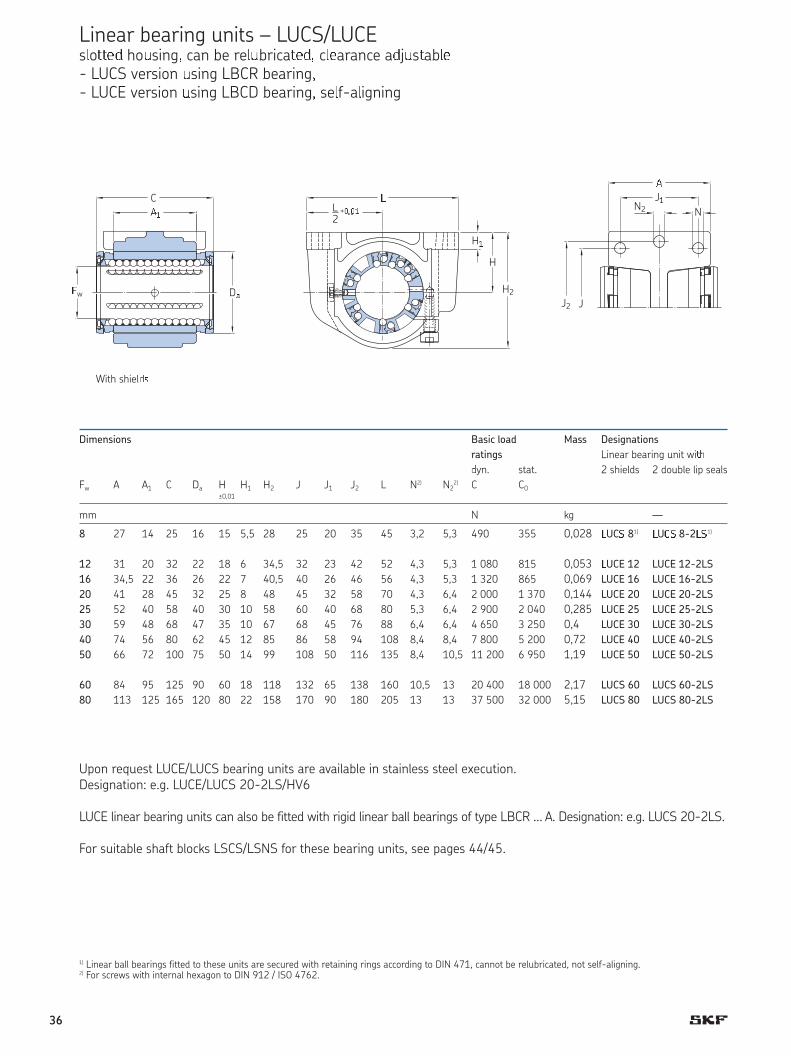
Linear bearing units – LUCR/LUCDclosed ho�sing, can be rel�brica��d- LUCR version �sing LBCR bearing - LUCD version using LBCD bearing, self-aligning
Dimensions Basic load Mass Designations
ratings Linear ball bearing unit with
dyn. stat. 2 shields 2 double lip seals
Fw A A1 C Da H H1 H2 J J1 J2 L N2) N22) C C0
±0,01
mm N kg
8 27 14 25 16 15 5,5 28 25 20 35 45 3,2 5,3 490 355 0,028 LUCR 81) LUCR 8-2LS1)
12 31 20 32 22 18 6 34,5 32 23 42 52 4,3 5,3 1 080 815 0,053 LUCD 12 LUCD 12-2LS
16 34,5 22 36 26 22 7 40,5 40 26 46 56 4,3 5,3 1 320 865 0,069 LUCD 16 LUCD 16-2LS
20 41 28 45 32 25 8 48 45 32 58 70 4,3 6,4 2 000 1 370 0,144 LUCD 20 LUCD 20-2LS
25 52 40 58 40 30 10 58 60 40 68 80 5,3 6,4 2 900 2 040 0,285 LUCD 25 LUCD 25-2LS
30 59 48 68 47 35 10 67 68 45 76 88 6,4 6,4 4 650 3 250 0,4 LUCD 30 LUCD 30-2LS
40 74 56 80 62 45 12 85 86 58 94 108 8,4 8,4 7 800 5 200 0,72 LUCD 40 LUCD 40-2LS
50 66 72 100 75 50 14 99 108 50 116 135 8,4 10,5 11 200 6 950 1,19 LUCD 50 LUCD 50-2LS
60 84 95 125 90 60 18 118 132 65 138 160 10,5 13 20 400 18 000 2,17 LUCR 60 LUCR 60-2LS
80 113 125 165 120 80 22 158 170 90 180 205 13 13 37 500 32 000 5,15 LUCR 80 LUCR 80-2LS
With shields
1) Linear ball bearings fitted to these units are secured with retaining rings according to DIN 471, cannot be relubricated, not self-aligning. 2) For screws with internal hexagon to DIN 912 / ISO 4762
LUCD/LUCR bearing units are available on request in stainless steel execution.Designation: e.g. LUCD/LUCR 20-2LS/HV6
LUCD linear ball bearing units can also be fitted with rigid linear ball bearings of type LBCR. Designation: e.g. LUCR 12-2LS.
LUCR/LUCD linear bearing units Fw 8-80 are also available fitted with linear plain bearings. Designation: e.g. LUCR 20 PA.
For suitable shaft blocks LSCS/LSNS for these bearing units, see pages 44/45.
��
H�
H2
N2
J�
JJ2
�
N
H
Fw D¡
CL2?¢£¢�
With shiel¤¥
35
Linear bearing units – LUCS/LUCEs¦o§§¨© hoªsing« can be re¦ªbrica§¨©« c¦¨arance a©jªs§ab¦¨- LUCS version ªsing LBCR bearing« - LUCE version ªsing LBCD bearing« se¦f-a¦igning
Dimensions Basic load Mass Designations
ratings Linear bearing unit wi¨yn. stat. 2 shields 2 double lip seals
Fw A A1 C Da H H1 H2 J J1 J2 L N2) N22) C C0
±0,01
mm N kg —
8 27 14 25 16 15 5,5 28 25 20 35 45 3,2 5,3 490 355 0,028 ¯UC° 81) ¯U±° 8-2¯°1)
12 31 20 32 22 18 6 34,5 32 23 42 52 4,3 5,3 1 080 815 0,053 ¯UCE 12 LUCE 12-2LS
16 34,5 22 36 26 22 7 40,5 40 26 46 56 4,3 5,3 1 320 865 0,069 LUCE 16 LUCE 16-2LS
20 41 28 45 32 25 8 48 45 32 58 70 4,3 6,4 2 000 1 370 0,144 LUCE 20 LUCE 20-2LS
25 52 40 58 40 30 10 58 60 40 68 80 5,3 6,4 2 900 2 040 0,285 LUCE 25 LUCE 25-2LS
30 59 48 68 47 35 10 67 68 45 76 88 6,4 6,4 4 650 3 250 0,4 LUCE 30 LUCE 30-2LS
40 74 56 80 62 45 12 85 86 58 94 108 8,4 8,4 7 800 5 200 0,72 LUCE 40 LUCE 40-2LS
50 66 72 100 75 50 14 99 108 50 116 135 8,4 10,5 11 200 6 950 1,19 LUCE 50 LUCE 50-2LS
60 84 95 125 90 60 18 118 132 65 138 160 10,5 13 20 400 18 000 2,17 LUCS 60 LUCS 60-2LS
80 113 125 165 120 80 22 158 170 90 180 205 13 13 37 500 32 000 5,15 LUCS 80 LUCS 80-2LS
With shields
1) Linear ball bearings fitted to these units are secured with retaining rings according to DIN 471, cannot be relubricated, not self-aligning.2) For screws with internal hexagon to DIN 912 / ISO 4762.
Upon request LUCE/LUCS bearing units are available in stainless steel execution.Designation: e.g. LUCE/LUCS 20-2LS/HV6
LUCE linear bearing units can also be fitted with rigid linear ball bearings of type LBCR … A. Designation: e.g. LUCS 20-2LS.
For suitable shaft blocks LSCS/LSNS for these bearing units, see pages 44/45.
²³´
H³
H2
N2
J³
JJ2
²
N
H
Dµ
CL2
+¶·¶³
With shiel ¹
ºw
36

Linear bearing units – LUCT/LUCFopen housing, can be relubricated, clearance adjustable- LUCT version using LBCT bearing - LUCF version using LBCF bearing, self-aligning
Dimensions Basic load Mass Designa»ions
r¼»in½s Linear bearing unit with
dyn. stat. 2 shields 2 double lip
Fw A A1 C Da H H1 H2 J J1 J2 L N2) N22) E1)
a C C0 seals±0,01
mm Deg. N kg —
12 31 20 32 22 18 6 28 32 23 42 52 4,3 5,3 7,6 78 1 080 815 0,046 LUCF 12 LUCF 12-2LS
16 34,5 22 36 26 22 7 35 40 26 46 56 4,3 5,3 10,4 78 1 320 865 0,061 LUCF 16 LUCF 16-2LS
20 41 28 45 32 25 8 42 45 32 58 70 4,3 6,4 10,8 60 2 000 1 370 0,124 LUCF 20 LUCF 20-2LS
25 52 40 58 40 30 10 51 60 40 68 80 5,3 6,4 13,2 60 2 900 2 040 0,251 LUCF 25 LUCF 25-2LS
30 59 48 68 47 35 10 60 68 45 76 88 6,4 6,4 14,2 50 4 650 3 250 0,374 LUCF 30 LUCF 30-2LS
40 74 56 80 62 45 12 77 86 58 94 108 8,4 8,4 18,7 50 7 800 5 200 0,63 LUCF 40 LUCF 40-2LS
50 66 72 100 75 50 14 88 108 50 116 135 8,4 10,5 23,6 50 11 200 6 950 1,04 LUCF 50 LUCF 50-2LS
60 84 95 125 90 60 18 105 132 65 138 160 10,5 13,0 29,6 54 20 400 18 000 2,0 LUCT 60 LUCT 60-2LS
80 113 125 165 120 80 22 140 170 90 180 205 13,0 13,0 38,4 54 37 500 32 000 5,0 LUCT 80 LUCT 80-2LS
With shields
1) Minimum sector width at diameter Fw. 2) For cylindrical screws with internal hexagon to DIN 912 / ISO 4762.
Upon request LUCF/LUCT bearing units are available in stainless steel execution.Designation: e.g. LUCF/LUCT 20-2LS/HV6
LUCF linear ball bearing units can also be fitted with rigid linear ball bearings of type LBCT … A. Designation: e.g. LUCT 20-2LS.
LUCF/LUCT linear bearing units Fw 12-80 are also available fitted with linear plain bearings. Designation: e.g. LUCT 20 PA.
For suitable shaft supports for these bearing units, designation LRCB/LRCC, see page 47.
¾¿
Àw Da
C L
Ea
H¿
H2
H
L2?ÁÂÁ¿ N2
J¿
JJ2
¾
N
With shielÃÄ
37

Linear bearing units – LUCÅ … BÆoÇen housing, can be relubricateÈÉ clearance aÈÊËstable- LUCÌ version using LBÍÌ bearing
Dimensions Basic load Mass Designations
ratings Linear bearings unit with
Îyn. stat. 2 shielÎs 2 ÎÏÐble lip seals
Fw A A1 C Da H H1 H2 J J1 J2 L N2) N22) E1)
a C C0±0,01
mm Deg. N kg —
20 41 28 45 32 25 8 42 45 32 58 70 4,3 6,4 10,8 60 2 650 2 650 0,14 LUÑT 20 BH LUÑT 20 BH-2LS25 52 40 58 40 30 10 51 60 40 68 80 5,3 6,4 13,2 60 4 900 5 100 0,275 LUCT 25 BH LUCT 25 BH-2LS
30 59 48 68 47 35 10 60 68 45 76 88 6,4 6,4 14,2 50 7 200 8 000 0,48 LUCT 30 BH LUCT 30 BH-2LS
40 74 56 80 62 45 12 77 86 58 94 108 8,4 8,4 18,7 50 11 600 11 400 0,86 LUCT 40 BH LUCT 40 BH-2LS
50 66 72 100 75 50 14 88 108 50 116 135 8,4 10,5 23,6 50 17 300 17 000 1,44 LUCT 50 BH LUCT 50 BH-2LS
With shields
1) Smallest sector width at diameter Fw. 2) For screws with internal hexagon to DIN 912 / ISO 4762.
Upon request LUCT bearing units are available in stainless steel execution.Designation: e.g. LUCT 20 BH-2LS/HV6
Suitable shaft supports, designation LRCB/LRCC, are available for these units. See page 47 for details.
A1
Fw Da
C L
Ea
H1
H2
H
L2?0,01
N2
J1
JJ2
A
N
With shields
38

Dimensions Basic load Mass Designations
ratings Linear bearing unit with
dyn. stat. 2 shields 2 double lip seals
Fw A Da H H1 H2 H3 H4 J J1 L N1) N11) C C0
±0,01
mm — N kg —
12 32 22 18 35 16,5 11 6 32 23 43 4,3 M 5 1 080 815 0,093 LUND 12 LUND 12-2LS
16 37 26 22 42 21 13 7 40 26 53 5,3 M 6 1 320 865 0,161 LUND 16 LUND 16-2LS
20 45 32 25 50 24 18 7,5 45 32 60 6,6 M 8 2 000 1 370 0,255 LUND 20 LUND 20-2LS
25 58 40 30 61 29 22 8,5 60 40 78 8,4 M 10 2 900 2 040 0,533 LUND 25 LUND 25-2LS
30 68 47 35 70 34 22 9,5 68 45 87 8,4 M 10 4 650 3 250 0,79 LUND 30 LUND 30-2LS
40 80 62 45 90 44 26 11 86 58 108 10,5 M 12 7 800 5 200 1,44 LUND 40 LUND 40-2LS
50 100 75 50 105 49 35 11 108 50 132 13,5 M 16 11 200 6 950 2,47 LUND 50 LUND 50-2LS
1) For screws with internal hexagon to DIN 912 / ISO 4762.
Upon request LUND bearing units are available in stainless steel execution.Designation: e.g. LUND 20-2LS/HV6
For suitable shaft blocks LSCS/LSNS for these bearing units, see pages 44/45.
Linear bearing units – LUNDclosed housing, can be relubricated- LUND version using LBCD bearing, self-aligning
With shields
With shielÒÓ
Ô
DÕ
H4
N1
H
L
H3
H1 J1
H2
N
J
Öw
L2?×Ø×Ù
39

Linear bearing units – LUNÚ slotted housing, can be relubricated, clearance adjustable- LUNÛ version using LBÜD bearing, self-aligning
Dimensions Basic load Mass Designations
ratings Linear bearing unit with
dyn. stat. 2 shields 2 double lip
Fw A Da H H1 H2 H3 H4 J J1 L N1) N11) C C0 seals
±0,01
mm — N kg —
12 32 22 18 35 16,5 11 6 32 23 43 4,3 M 5 1 080 815 0,093 LUNE 12 LUNE 12-2LS
16 37 26 22 42 21 13 7 40 26 53 5,3 M 6 1 320 865 0,161 LUNE 16 LUNE 16-2LS
20 45 32 25 50 24 18 7,5 45 32 60 6,6 M 8 2 000 1 370 0,255 LUNE 20 LUNE 20-2LS
25 58 40 30 61 29 22 8,5 60 40 78 8,4 M 10 2 900 2 040 0,533 LUNE 25 LUNE 25-2LS
30 68 47 35 70 34 22 9,5 68 45 87 8,4 M 10 4 650 3 250 0,79 LUNE 30 LUNE 30-2LS
40 80 62 45 90 44 26 11 86 58 108 10,5 M 12 7 800 5 200 1,44 LUNE 40 LUNE 40-2LS
50 100 75 50 105 49 35 11 108 50 132 13,5 M 16 11 200 6 950 2,47 LUNE 50 LUNE 50-2LS
With shields
1) For screws with internal hexagon to DIN 912 / ISO 4762.
Upon request LUNE bearing units are available in stainless steel execution.Designation: e.g. LUNE 20-2LS/HV6
For suitable shaft blocks LSCS/LSNS for these bearing units, see pages 44/45.
With shields
A
DaFw
H4
N1
H
L
H3
H1
H2
N
J
L2?0,01
J1
40

Dimensions Basic load Mass Designations
ratings Linear bearing unit with
dyn. stat. 2 shields 2 double lip
Fw A Da H H1 H2 H3 H4 J J1 L N2) N12) E1)
a C C0 seals±0,0Ý
mm — mm Deg. N kg —
12 32 22 18 28 16,5 ÞÞ 6 32 23 ß3 ß,3 M 5 7,6 78 Þ 080 8Þ5 0,07ß LUNF 12 LUNF 12-2LS
16 37 26 22 35 2Þ Þ3 7 ß0 26 53 5,3 M 6 10,ß 78 Þ 320 865 0,Þ32 LUNF 16 LUNF 16-2LS
20 ß5 32 25 ß2 2ß Þ8 7,5 ß5 32 60 6,6 M 8 10,8 60 2 000 Þ 370 0,2Þ5 LUNF 20 LUNF 20-2LS
25 58 ß0 30 5Þ 29 22 8,5 60 ß0 78 8,ß M 10 Þ3,2 60 2 900 2 0ß0 0,ßß3 LUNF 25 LUNF 25 -2LS
30 68 ß7 35 60 3ß 22 9,5 68 ß5 87 8,ß M 10 Þß,2 50 ß 650 3 250 0,67 LUNF 3 0 LUNF 30-2LS
40 80 62 ß5 77 ßß 26 ÞÞ 86 58 Þ08 Þ0,5 M 12 18,7 50 7 800 5 200 Þ,2Þ LUNF 40 LUNF 40-2LS
50 Þ00 75 50 88 ß9 35 ÞÞ Þ08 50 Þ32 Þ3,5 M 16 23,6 50 ÞÞ 200 6 950 2,02 LUNF 50 LUNF 50-2LS
With shields
1) Smallest sector width at diameter Fw. 2) For screws with internal hexagon to DIN 912 / ISO 4762.
Upon request LUNF bearing units are available in stainless steel execution.Designation: e.g. LUNF 20-2LS/HV6
Suitable shaft supports, designation LRCB/LRCC are aàailable for these units. See page 47 áor details.
Linear bearing units – LUNFopen housing, can be relubricated, clearance adjustable- LUNF version using LBCF bearing, self-aligning
With shielâãE
a
Fw Dä
å
Hæ
N1
H
L
H3
H1
H2
N
J
L2?çèçé
J1
41

êëìíîïð ëiíïìr ñïìriíî òíiós – ôVCRcõös÷ø hoùsiúûü ýVCR ùsiúû ýBCR þ÷ÿriúû
���� ����� �ip s���s
�) ��r scr�ws wi�h i���r��� h�x��o� �o DIN 912 / ISO 4762. 2) Linear ball bearings fitted to these units are secured using pins according to DIN 1470. They are not designed for relubrication.
Upon request LVCR bearing units are available in stainless steel execution.Designation: e.g. LVCR 20-2LS/HV6
LVCR linear ball bearing units of sizes Fw 12-50 can also be fitted with linear bearings which are self-aligningDesignation: e.g. LVCD 12-2LS.
Dimensions Basic load ratings Mass Designations
Linear bearing unit 2)
dyn. stat. with 2 double lip seals
Fw A A1 C Da D2 J L N1) C C0
mm N kg —
12 20 8 32 22 32 30 42 5,5 1 160 980 0,113 L�CR 12-2LS
16 22 8 36 26 38 35 50 5,5 1 500 1 290 0,161 L�CR 16-2LS
20 28 10 45 32 46 42 60 6,6 2 240 2 040 0,314 L�CR 20-2LS
25 40 12 58 40 58 54 74 6,6 3 350 3 350 0,655 L�CR 25-2LS
30 48 14 68 47 66 60 84 9 5 600 5 700 0,98 L�CR 30-2LS
40 56 16 80 62 90 78 108 11 9 000 8 150 1,91 L�CR 40-2LS
50 72 18 100 75 110 98 130 11 13 400 12 200 3,27 L�CR 50-2LS
60 95 22 125 90 135 120 160 13,5 20 400 18 000 5,92 L�CR 60-2LS
8 0 125 25 165 120 180 155 200 13,5 37 500 32 000 13,3 L�CR 8 0-2LS
LFwD2
A1
A
C
Da
N
J
L
J
With double lip seals
42
Dimensions Basic load Mass Designations
ratings Linear bearing unit
dyn. stat. with double lip seals
Fw A C Da H H1 H2 H3 J J1 L N1) N11) C C0
±0,01
mm — N kg —
12 76 32 22 18 35 27 13 30 40 42 5,3 M 6 1 760 1 630 0,236 LTCD 12-2LS
16 84 36 26 22 41,5 33 13 36 45 50 5,3 M 6 2 160 1 730 0,372 LTCD 16-2LS
20 104 45 32 25 49,5 39,5 18 45 55 60 6,4 M 8 3 200 2 750 0,67 LTCD 20 -2LS
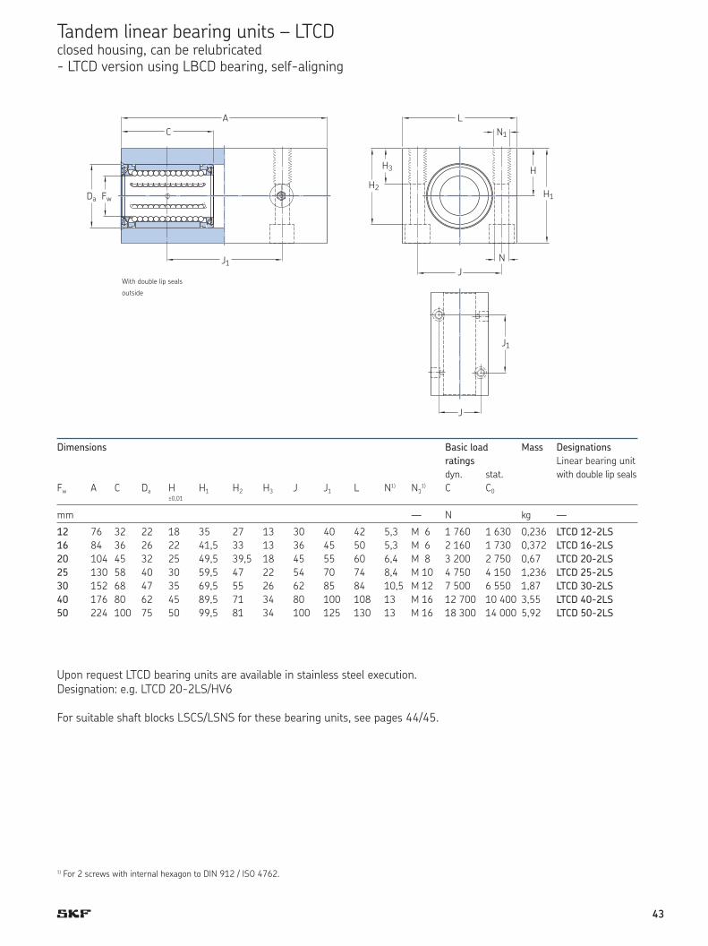
25 130 58 40 30 59,5 47 22 54 70 74 8,4 M 10 4 750 4 150 1,236 LTCD 25-2LS
30 152 68 47 35 69,5 55 26 62 85 84 10,5 M 12 7 500 6 550 1,87 LTCD 30-2LS
40 176 80 62 45 89,5 71 34 80 100 108 13 M 16 12 700 10 400 3,55 LTCD 40-2LS
50 224 100 75 50 99,5 81 34 100 125 130 13 M 16 18 300 14 000 5,92 LTCD 50-2LS
With double lip seals on the outside
Upon request LTCD bearing units are available in stainless steel execution.Designation: e.g. LTCD 20-2LS/HV6
For suitable shaft blocks LSCS/LSNS for these bearing units, see pages 44/45.
Tandem linear bearing units – LTCDclosed housing, can be relubricated- LTCD version using LBCD bearing, self-aligning
1) For 2 screws with internal hexagon to DIN 912 / ISO 4762.
J1
J
H3
H2H1
H
L
J
N1
N
J1
J
With double lip seals
outside
FwDa
J1
C
A
43
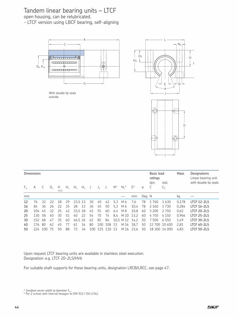
Tandem linear bearing units – LTCFopen housing, can be relubricated.- LTCF version using LBCF bearing, self-aligning
±0,01
mm — mm Deg. N kg —
12 76 32 22 18 29 23,5 13 30 40 42 5,3 M 6 7,6 78 1 760 1 630 0,178 LTCF 12-2LS
16 84 36 26 22 35 28 13 36 45 50 5,3 M 6 10,4 78 2 160 1 730 0,284 LTCF 16-2LS
20 104 45 32 25 42 33,5 18 45 55 60 6,4 M 8 10,8 60 3 200 2 750 0,62 LTCF 20-2LS
25 130 58 40 30 51 40 22 54 70 74 8,4 M 10 13,2 60 4 750 4 150 0,966 LTCF 25-2LS
30 152 68 47 35 60 46,5 26 62 85 84 10,5 M 12 14,2 50 7 500 6 550 1,49 LTCF 30-2LS
40 176 80 62 45 77 61 34 80 100 108 13 M 16 18,7 50 12 700 10 400 2,81 LTCF 40-2LS
50 224 100 75 50 88 72 34 100 125 130 13 M 16 23,6 50 18 300 14 000 4,83 LTCF 50-2LS
1) Smallest sector width at diameter Fw. 2) For 2 screws with internal hexagon to DIN 912 / ISO 4762.
Upon request LTCF bearing units are available in stainless steel execution.Designation: e.g. LTCF 20-2LS/HV6
For suitable shaft supports for these bearing units, designation LRCB/LRCC, see page 47.
J1
J
C
J1
�w
H3 H
H
L
N1
NE
a
J
J1
J
H2
Da
A
With double l ip sealsoutside
Dimensions Basic load Mass Designations
ratings Linear bearing unit
dyn. stat. with double lip seals
Fw A C Da H H1 H2 H3 J J1 L N2) N12) E1)
a C C0±0,01
mm — mm Deg. N kg —
12 76 32 22 18 29 23,5 13 30 40 42 5,3 M 6 7,6 78 1 760 1 630 0,178 LTCF 12-2LS
16 84 36 26 22 35 28 13 36 45 50 5,3 M 6 10,4 78 2 160 1 730 0,284 LTCF 16-2LS
20 104 45 32 25 42 33,5 18 45 55 60 6,4 M 8 10,8 60 3 200 2 750 0,62 LTCF 20-2LS
25 130 58 40 30 51 40 22 54 70 74 8,4 M 10 13,2 60 4 750 4 150 0,966 LTCF 25-2LS
30 152 68 47 35 60 46,5 26 62 85 84 10,5 M 12 14,2 50 7 500 6 550 1,49 LTCF 30-2LS
40 176 80 62 45 77 61 34 80 100 108 13 M 16 18,7 50 12 700 10 400 2,81 LTCF 40-2LS
50 224 100 75 50 88 72 34 100 125 130 13 M 16 23,6 50 18 300 14 000 4,83 LTCF 50-2LS
Upon request LTCF bearing units are available in stainless steel execution.Designation: e.g. LTCF 20-2LS/HV6
For suitable shaft supports for these bearing units, designation LRCB/LRCC, see page 47.
44

Dimensions Basic load Mass Designations
ratings Linear bearing unit
dyn. stat. with double lip
Fw �a H H1 H2 H3 J L L1 N2) N12) C C0 seals
±0,01
mm — N kg —
8 25 16 11,5 23 17,5 11 55 65 32 4,3 M 5 1 290 1 420 0,226 LQCR 8-2LS1)
12 32 22 16 32 25 13 73 85 42 5,3 M 6 2 850 3 250 0,492 LQCD 12-2LS
16 36 26 18 36 29 13 88 100 54 5,3 M 6 3 450 3 450 0,744 LQCD 16-2LS
20 45 32 23 46 37,5 18 115 130 72 6,6 M 8 5 200 5 500 1,68 LQCD 20-2LS
25 58 40 28 56 45 22 140 160 88 8,4 M 10 7 650 8 150 3,022 LQCD 25-2LS
30 68 47 32 64 50,5 26 158 180 96 10,5 M 12 12 200 12 900 4,27 LQCD 30-2LS
40 80 62 40 80 64 34 202 230 122 13,5 M 16 20 800 20 800 8,38 LQCD 40-2LS
50 100 75 48 96 80 34 250 280 152 13,5 M 16 30 000 28 000 14,99 LQCD 50-2LS
With double lip seals on the outside
1) Unit with linear ball bearing not designed for re-greasing, non self-aligning.2) For 4 cylindrical screws with internal hexagon to DIN 912 / ISO 4762.
Upon request LQCR/LQCD bearing units are available in stainless steel execution.Designation: e.g. LQCR/LQCD 20-2LS/HV6
For suitable shaft blocks for these bearing units, designation LEAS … A and LEAS … B, see page 46.
Quadro linear bearing units – LQCR/LQCDclosed housing, can be relubricated.- LQCR version using LBCR bearing- LQCD version using LBCD bearing, self-aligning
J
J
L
H
H1
N1
NL1
J
J
With double lip seals outside
C
L
FwDa
H3
H2
J
Dimensions Basic load Mass Designations
ratings Linear bearing unit
dyn. stat. with double lip
Fw C Da H H1 H2 H3 J L L1 N2) N12) C C0 seals
±0,01
mm — N kg —
8 25 16 11,5 23 17,5 11 55 65 32 4,3 M 5 1 290 1 420 0,226 LQCR 8-2LS1)
12 32 22 16 32 25 13 73 85 42 5,3 M 6 2 850 3 250 0,492 LQCD 12-2LS
16 36 26 18 36 29 13 88 100 54 5,3 M 6 3 450 3 450 0,744 LQCD 16-2LS
20 45 32 23 46 37,5 18 115 130 72 6,6 M 8 5 200 5 500 1,68 LQCD 20-2LS
25 58 40 28 56 45 22 140 160 88 8,4 M 10 7 650 8 150 3,022 LQCD 25-2LS
30 68 47 32 64 50,5 26 158 180 96 10,5 M 12 12 200 12 900 4,27 LQCD 30-2LS
40 80 62 40 80 64 34 202 230 122 13,5 M 16 20 800 20 800 8,38 LQCD 40-2LS
50 100 75 48 96 80 34 250 280 152 13,5 M 16 30 000 28 000 14,99 LQCD 50-2LS
Upon request LQCR/LQCD bearing units are available in stainless steel execution.Designation: e.g. LQCR/LQCD 20-2LS/HV6
For suitable shaft blocks for these bearing units, designation LEAS … A and LEAS … B, see page 46.
45
Dimensions Basic load Mass Designations
ratings Linear bearing unit
dyn. stat. with double lip
Fw C Da H H H2 H3 J L L N2) N 2) E�) a C C0 seals±0,0
mm — mm Deg. N kg —
12 32 22 �8 30 23,4 �3 73 85 42 5,3 M 6 7,6 78 2 850 3 250 0,426 LQCF 12-2LS
16 36 26 22 35 28,4 �3 88 �00 54 5,3 M 6 �0,4 78 3 450 3 450 0,698 LQCF 16-2LS
20 45 32 25 42 33,5 �8 ��5 �30 72 6,6 M 8 �0,8 60 5 200 5 500 �,42 LQCF 20-2LS
25 58 40 30 5� 40 22 �40 �60 88 8,4 M �0 �3,2 60 7 650 8 �50 2,572 LQCF 25-2LS
30 68 47 35 60 46,5 26 �58 �80 96 �0,5 M �2 �4,2 50 �2 200 �2 900 3,79 LQCF 30-2LS
40 80 62 45 77 6� 34 202 230 �22 �3,5 M �6 �8,7 50 20 800 20 800 7,8 LQCF 40-2LS
50 �00 75 55 93 77 34 250 280 �52 �3,5 M �6 23,6 50 30 000 28 000 �3,96 LQCF 50-2LS
With double lip seals on the outside
�) Smallest sector width at diameter Fw. 2) For 4 cylindrical screws with internal hexagon to DIN 9�2 / ISO 4762.
Upon request LQCF bearing units are available in stainless steel execution.Designation: e.g. LQCF 20-2LS/HV6
For suitable shaft supports for these bearing units, designation LRCB/LRCC, see page 47.
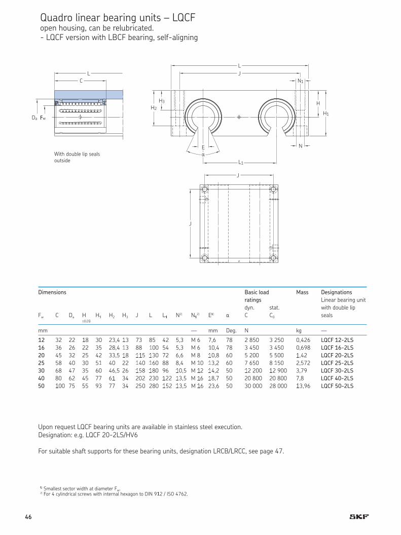
Quadro linear bearing units – LQCF open housing, can be relubricated.- LQCF version with LBCF bearing, self-aligning
J
J
C
�w
H3
N1
N
J
Da
L
L
E
H
H1
H2
J
L1
J
With double lip sealsoutside
a
Dimensions Basic load Mass Designations
ratings Linear bearing unit
dyn. stat. with double lip
Fw C Da H H H2 H3 J L L N2) N 2) E�) a C C0 seals±0,0
mm — mm Deg. N kg —
12 32 22 �8 30 23,4 �3 73 85 42 5,3 M 6 7,6 78 2 850 3 250 0,426 LQCF 12-2LS
16 36 26 22 35 28,4 �3 88 �00 54 5,3 M 6 �0,4 78 3 450 3 450 0,698 LQCF 16-2LS
20 45 32 25 42 33,5 �8 ��5 �30 72 6,6 M 8 �0,8 60 5 200 5 500 �,42 LQCF 20-2LS
25 58 40 30 5� 40 22 �40 �60 88 8,4 M �0 �3,2 60 7 650 8 �50 2,572 LQCF 25-2LS
30 68 47 35 60 46,5 26 �58 �80 96 �0,5 M �2 �4,2 50 �2 200 �2 900 3,79 LQCF 30-2LS
40 80 62 45 77 6� 34 202 230 �22 �3,5 M �6 �8,7 50 20 800 20 800 7,8 LQCF 40-2LS
50 �00 75 55 93 77 34 250 280 �52 �3,5 M �6 23,6 50 30 000 28 000 �3,96 LQCF 50-2LS
Upon request LQCF bearing units are available in stainless steel execution.Designation: e.g. LQCF 20-2LS/HV6
For suitable shaft supports for these bearing units, designation LRCB/LRCC, see page 47.
46

Among shaft carriers, a distinction ismade between shaft blocks and shaftsupports. Shaft blocks support theshaft only at its ends; shaft supportstypically run the entire length of theshaft and therefore require the useof open linear bearing units.
LSCS shaf t blocks are made of castaluminium and designed to grip theend of the shaft. These blocks aresupplied as standard with two holesdrilled in the base for attachment.LSCS shaft blocks are suitable forshaft diameters ranging from 8 to 80 mm.
LSNS and LSHS shaft blocks aremade of extruded aluminium. Theycan be attached by through bolts orthey can be bolted, via threaded ho-les, directly to the support surface.
LRCB/LRCC shaft supportsFor heavily loaded linear bearingunits and/or long track lengths, SKFrecommends the use of shaft sup-ports to eliminate shaft bending. Forthese applications, continuous or atleast partial support of the shaft isnecessary. SKF offers shaft supportsfor shaft diameters ranging from 12to 80 mm. There are two types ofshaft support: the LRCB with predril-led holes and the LRCC without ho-les.
Note: Shaft supports require the useof open design linear bearing units.
LSNS and LSHS shaft blocks areavailable for shaft diameters rangingfrom 12 to 50 mm.
LEBS/LEAS tandem shaft blocks To match the duo and quadro linearbearing units with ISO series 1 linearball bearings (LBBR), LEBS tandemshaft blocks are available in the “A”design, where the shaft block is fixedand the linear bearing moves axially.LEBS shaft blocks are available forshaft diameters ranging from 12 to50 mm. For units with ISO series 3linear ball bearings (LBC/LBHT) LEAS tandem shaft blocks are avai-lable in both the “A” and “B” design.The “B” design enables axial move-ment of the shafts through a fixed linear bearing unit. LEAS shaftblocks are available for shaft diame-ters ranging from 8 to 50 mm.
Shaft carriers / shaft blocks
LEAS/LEBSLSCS
LRCB
LJM
47

Dimensions Mass Designa�ions
Shaf� bl ck
da A H H1 H2 J J2 J3 L L1 N1) N2±0,01
mm kg —
8 10 15 5,5 25 25 35 5 45 19 4,3 2,7 0,012 !"#" 8
12 12 20 6 32,5 32 42 6 52 25 5,3 3,2 0,023 !"#" 12
16 15 20 7 35,5 40 46 7,5 56 31,8 5,3 4,3 0,034 !"#" 16
20 20 25 8 43,5 45 58 10 70 37 5,3 5,3 0,065 LSCS 20
25 28 30 10 53 60 68 16 80 48 6,4 6,4 0,14 LSCS 25
30 30 35 10 63 68 76 18 88 56 8,4 6,4 0,20 LSCS 30
40 36 45 12 81 86 94 22 108 71 10,5 8,4 0,47 LSCS 40
50 49 50 14 92,5 108 116 30 135 86 10,5 10,5 0,68 LSCS 50
60 62 60 18 112 132 138 40 160 105 13 13 1,29 LSCS 60
80 85 80 22 147,5 170 180 60 205 136 17 15 3,01 LSCS 80
1) For screws with internal hexagon to DIN 912 / ISO 4762.
Shaft blocks – LSCS
da
H
NJ3
J
N2
J2
L
L1
A
H2
H1
L2?0$01
48

Dimensions Mass Designations
S%&ft block
da A H H1 H2 H3 H4 J L2) N1) N11)
±0,01
mm kg —
12 20 20 6 35 13 16,5 30 43 5,3 M 6 0,06 LSNS 12
16 24 25 7 42 18 21 38 53 6,6 M 8 0,11 LSNS 16
20 30 30 7,5 50 22 25 42 60 8,4 M 10 0,17 LSNS 20
25 38 35 8,5 61 26 30 56 78 10,5 M 12 0,34 LSNS 25
30 40 40 9,5 70 26 34 64 87 10,5 M 12 0,46 LSNS 30
40 48 50 11 90 34 44 82 108 13,5 M 16 0,90 LSNS 40
50 58 60 11 105 43 49 100 132 17,5 M 20 1,45 LSNS 50
12 18 19 — 33 13 16,5 27 40 5,3 M 6 0,05 LSHS 12
16 20 22 — 38 13 18 32 45 5,3 M 6 0,07 LSHS 16
20 24 25 — 45 18 21 39 53 6,6 M 8 0,11 LSHS 20
25 28 31 — 54 22 25 44 62 8,4 M 10 0,17 LSHS 25
30 30 34 — 60 22 29 49 67 8,4 M 10 0,22 LSHS 30
40 40 42 — 76 26 37 66 87 10,5 M 12 0,47 LSHS 40
50 50 50 — 92 34 44 80 103 13,5 M 16 0,82 LSHS 50
1) For screws with internal hexagon to DIN 912 / ISO 4762.2) Tolerance L/2 ± 0,01 only by execution LSNS.
Shaft blocks – LSNS/LSHSin combination with linear ball bearings acc. to ISO series 1 and ISO series 3
Design versionsLSHS = Shaft blocks with ISO series 1 LBBR bearingsLSNS = Shaft blocks with ISO series 3 LBC/LBH bearings
N'H3
(
H'
H4
d)
H
H2
*
De+,-. /e2+,s.+(SHS 3 S567t 89so:+ ;,t5 <S= +e2,e+ > (??@ 8e62,.-+(SNS 3 S567t 89so:+ ;,t5 <S= +e2,e+ B (?CD(?H 8e62,.-+
N
J
(2?EGE'
49
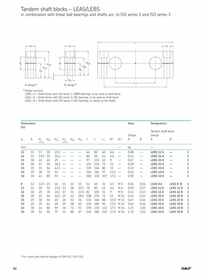
A-design* B-design*
1) For screws with internal hexagon to DIN 912 / ISO 4762.
Tandem shaft blocks – LEAS/LEBSin combination with linear ball bearings and shafts acc. to ISO series 1 and ISO series 3
Design versionsLEBS … A = Shaft blocks with ISO series 1 LBBR bearings, to be used as shaft blockLEAS … A = Shaft blocks with ISO series 3 LBC bearings, to be used as shaft blockLEAS … B = Shaft blocks with ISO series 3 LBC bearings, to clamp on the shafts
*
*
Dimensions Mass Designations
IIO
Tandem shaft block
Design Design
da A HA H1A H2A HB H1B H2B J L L1 N1) N11) A B A B
±0,015 ±0,015
mm — kg —
12 15 17 30 21,5 — — — 64 80 40 6,6 — 0,08 — KEBS 12 A — 1
16 15 19,5 35 26,5 — — — 80 96 52 6,6 — 0,11 — LEBS 16 A — 1
20 18 22 40 29 — — — 97 115 63 9 — 0,17 — LEBS 20 A — 1
25 20 27 50 36,5 — — — 115 136 75 11 — 0,28 — LEBS 25 A — 1
30 20 31 56 42,5 — — — 125 146 80 11 — 0,32 — LEBS 30 A — 1
40 25 38 70 54 — — — 160 184 97 13,5 — 0,63 — LEBS 40 A — 1
50 30 43 80 59 — — — 180 210 107 17,5 — 0,90 — LEBS 50 A — 1
8 12 12,5 23 16 11 22 15 52 65 32 5,5 M 5 0,04 0,04 LEAS 8 A LEAS 8 B 3
12 14 18 32 23,5 14 28 19,5 70 85 42 6,6 M 6 0,09 0,07 LEAS 12 A LEAS 12 B 3
16 18 20 36 26,5 17 34 23,5 82 100 54 9 M 8 0,14 0,13 LEAS 16 A LEAS 16 B 3
20 20 25 46 32,5 21 42 28,5 108 130 72 11 M 10 0,25 0,22 LEAS 20 A LEAS 20 B 3
25 25 30 56 40 26 52 36 132 160 88 13,5 M 12 0,47 0,44 LEAS 25 A LEAS 25 B 3
30 25 35 64 48 29 58 42 150 180 96 13,5 M 12 0,62 0,56 LEAS 30 A LEAS 30 B 3
40 30 44 80 59 36 72 51 190 230 122 17,5 M 16 1,15 1,00 LEAS 40 A LEAS 40 B 3
50 30 52 96 75 44 88 67 240 280 152 17,5 M 16 1,70 1,52 LEAS 50 A LEAS 50 B 3
A A
da da
HB
H2B
H1B
HA
H2A
H1A
N1
NL
L1
J
*
A-design*)
Design versionsLEBS...A = Shaft blocks with ISO series 1 LBBR bearings, to be used as shaft blockLEAS...A = Shaft blocks with ISO series 3 LBC bearings, to be used as shaft blockLEAS...B = Shaft blocks with ISO series 3 LBC bearings, to clamp on the shafts
B-design*)
*)
50
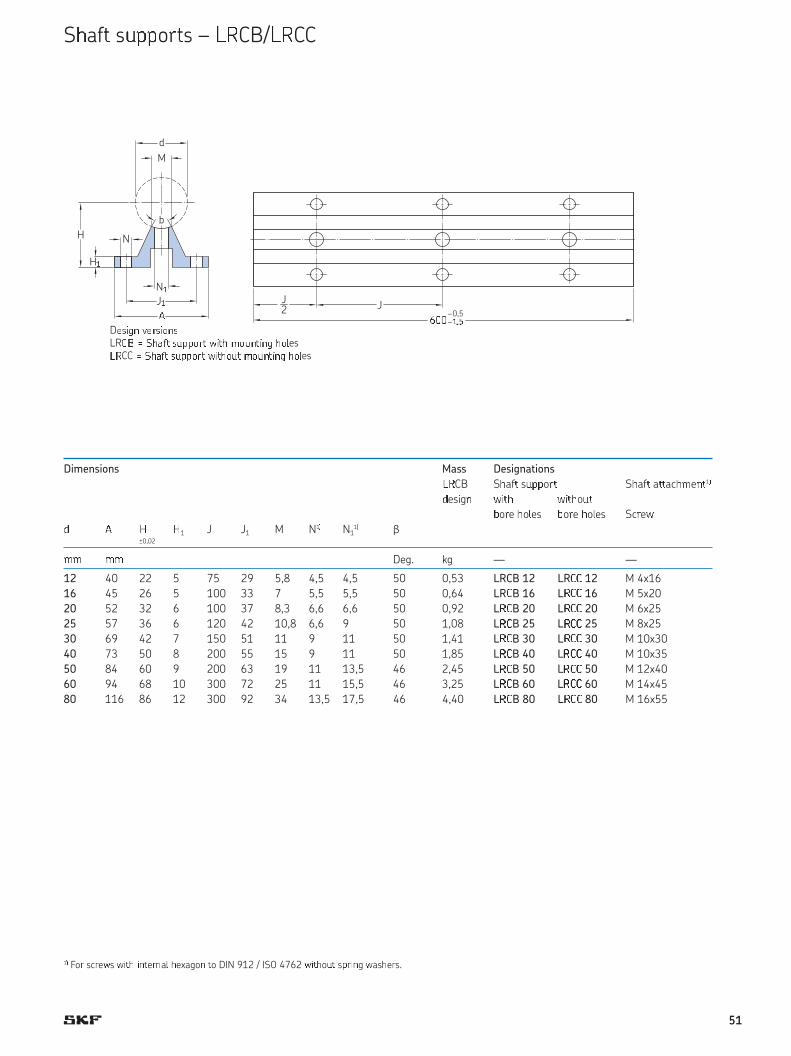
Dimensions Mass Designations
MOCB SPafQ sRTToUQ SPafQ aQQacPVeWQ1XYesZgW [ZQP [ZQPoRQ
\oUe Po]es \oUe Po]es ScUe[Y ^ _ _1 J J1 M N1X N1
1X b±0,02
VV VV Deg. kg — —
12 40 22 5 75 29 5,8 4,5 4,5 50 0,53 LRCB 12 LR`` 12 M 4x16
16 45 26 5 100 33 7 5,5 5,5 50 0,64 LR`B 16 Lb`` 16 M 5x20
20 52 32 6 100 37 8,3 6,6 6,6 50 0,92 Lb`B 20 Lb`` 20 M 6x25
25 57 36 6 120 42 10,8 6,6 9 50 1,08 Lb`B 25 Lb`` 25 M 8x25
30 69 42 7 150 51 11 9 11 50 1,41 Lb`B 30 Lb`` 30 M 10x30
40 73 50 8 200 55 15 9 11 50 1,85 Lb`B 40 Lb`` 40 M 10x35
50 84 60 9 200 63 19 11 13,5 46 2,45 Lb`B 50 Lb`` 50 M 12x40
60 94 68 10 300 72 25 11 15,5 46 3,25 Lb`B 60 Lb`` 60 M 14x45
80 116 86 12 300 92 34 13,5 17,5 46 4,40 Lb`B 80 Lb`` 80 M 16x55
Descgf vegscofshiCB = Sjafk slmmogk nckj polfkcfg joqeshiCC = Sjafk slmmogk nckjolk polfkcfg joqes
1r Fou scuevsvwxy wzxeuza{ yexagoz xo DIN 912 / ISO 4762 vwxyo|x s}uwzgvasyeus.
S~af� s���o��s – ��CB/��CC
D����� ��������LR�� � ����� ������� ���� �������� ���es��CC � ����� ������� ������� �������� ���es
J2
���–0,5–��
J
N�
M
d
b
H�
H N
J�¡
51
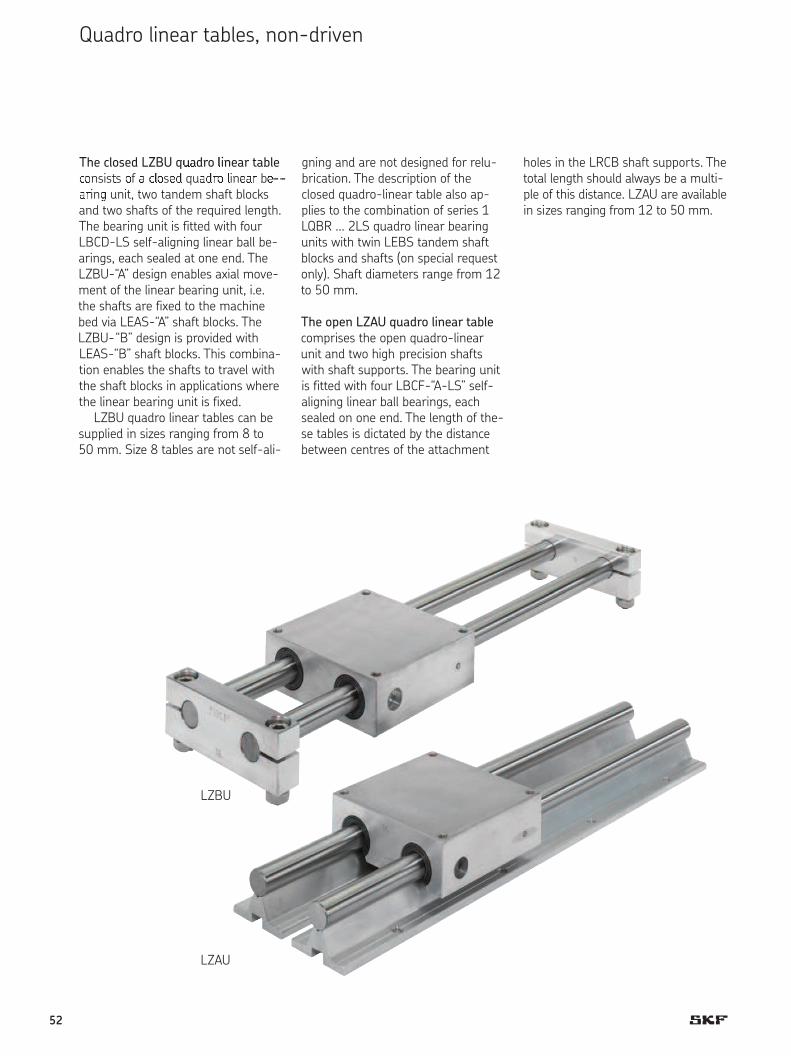
The closed LZBU q ¢£dro ¤inear table¥¦nsis§s ¦f ¨ ¥©¦sª« qu¨«¬¦ ©inª ¬ bª¬in® unit, two tandem shaft blocks
and two shafts of the required length.The bearing unit is fitted with fourLBCD-LS self-aligning linear ball be-arings, each sealed at one end. TheLZBU-“A” design enables axial move-ment of the linear bearing unit, i.e.the shafts are fixed to the machinebed via LEAS-“A” shaft blocks. TheLZBU-“B” design is provided with LEAS-“B” shaft blocks. This combina-tion enables the shafts to travel withthe shaft blocks in applications wherethe linear bearing unit is fixed.
LZBU quadro linear tables can besupplied in sizes ranging from 8 to 50 mm. Size 8 tables are not self-ali-
holes in the LRCB shaft supports. Thetotal length should always be a multi-ple of this distance. LZAU are availablein sizes ranging from 12 to 50 mm.
gning and are not designed for relu-brication. The description of the closed quadro-linear table also ap-plies to the combination of series 1LQBR … 2LS quadro linear bearingunits with twin LEBS tandem shaftblocks and shafts (on special requestonly). Shaft diameters range from 12to 50 mm.
The open LZAU quadro linear table
comprises the open quadro-linearunit and two high precision shaftswith shaft supports. The bearing unitis fitted with four LBCF-“A-LS” self-aligning linear ball bearings, eachsealed on one end. The length of the-se tables is dictated by the distancebetween centres of the attachment
Quadro linear tables, non-driven
LZAU
LZBU
52
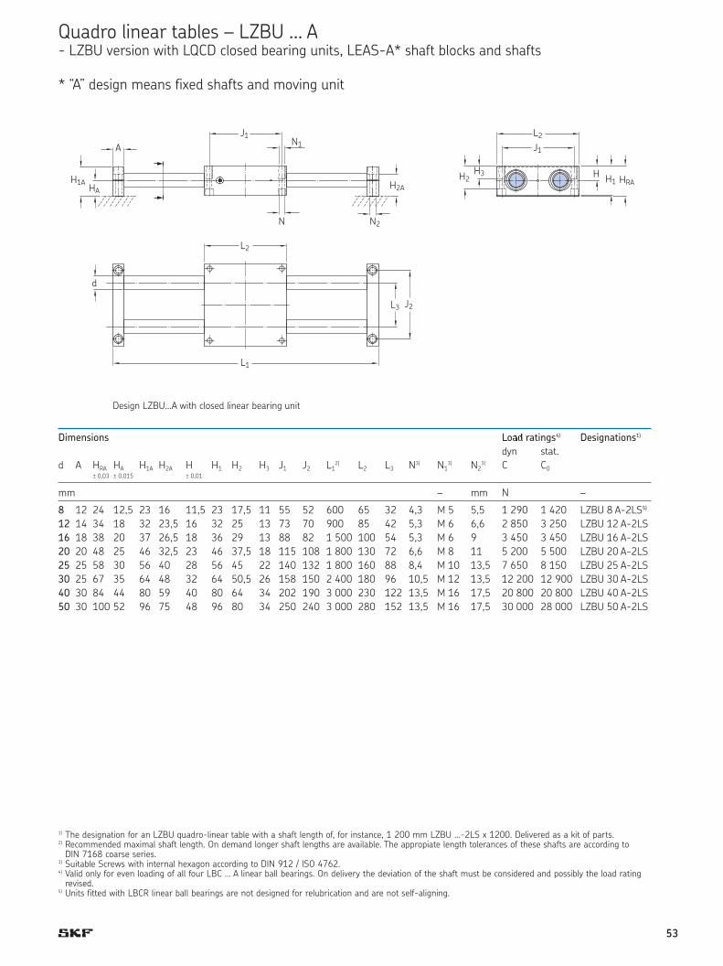
Design LZBU … A with closed linear bearing unit
Quadro linear tables – LZBU … A - LZBU version with LQCD closed bearing units, LEAS-A* shaft blocks and shafts
* “A” design means fixed shafts and moving unit
1) The designation for an LZBU quadro-linear table with a shaft length of, for instance, 1 200 mm LZBU …-2LS x 1200. Delivered as a kit of parts.2) Recommended maximal shaft length. On demand longer shaft lengths are available. The appropiate length tolerances of these shafts are according to
DIN 7168 coarse series.3) Suitable Screws with internal hexagon according to DIN 912 / ISO 4762.4) Valid only for even loading of all four LBC … A linear ball bearings. On delivery the deviation of the shaft must be considered and possibly the load rating
revised.5) Units fitted with LBCR linear ball bearings are not designed for relubrication and are not self-aligning.
Dimensions Lo¯° ratings4) Designations1)
dyn stat.
d A HRA HA H1A H2A H H1 H2 H3 J1 J2 L12) L2 L3 N3) N1
3) N23) C C0
± 0,03 ± 0,015 ± 0,01
mm – mm N –
8 12 24 12,5 23 16 11,5 23 17,5 11 55 52 600 65 32 4,3 M 5 5,5 1 290 1 420 LZBU 8 A-2LS5)
12 14 34 18 32 23,5 16 32 25 13 73 70 900 85 42 5,3 M 6 6,6 2 850 3 250 LZBU 12 A-2LS
16 18 38 20 37 26,5 18 36 29 13 88 82 1 500 100 54 5,3 M 6 9 3 450 3 450 LZBU 16 A-2LS
20 20 48 25 46 32,5 23 46 37,5 18 115 108 1 800 130 72 6,6 M 8 11 5 200 5 500 LZBU 20 A-2LS
25 25 58 30 56 40 28 56 45 22 140 132 1 800 160 88 8,4 M 10 13,5 7 650 8 150 LZBU 25 A-2LS
30 25 67 35 64 48 32 64 50,5 26 158 150 2 400 180 96 10,5 M 12 13,5 12 200 12 900 LZBU 30 A-2LS
40 30 84 44 80 59 40 80 64 34 202 190 3 000 230 122 13,5 M 16 17,5 20 800 20 800 LZBU 40 A-2LS
50 30 100 52 96 75 48 96 80 34 250 240 3 000 280 152 13,5 M 16 17,5 30 000 28 000 LZBU 50 A-2LS
J1A
HA
L2
L1
H1A
J1N1
H2A
J1
L2
H3 HH1 HRA
N2
L3 J2
N
d
H2
Design LZBU…A with closed linear bearing unit
53

Q±²dro ³´µe²r ¶²·³¸s – ¹ZBU … B - ºZBU »ersio¼ ½¾¿À ºQCD cÁosed ÂÃÄž¼Æ Ǽ¾¿s, ºEAS-È* sÀÄf¿ ÂÁocks ļd sÀÄf¿s
* “B” desig¼ meļs f¾xed Ǽ¾¿ ļd mo»¾¼g sÀÄf¿s
DesigÉ ÊZBU … B ËÌÍÎ cÏosed liÉeÐr ÑÒÐÓÌÉÔ ÕÉÌÍ
Dimensions LoÖ× ratings4) Designations1)
ØyÙ sÚÛÚ.d A HRB HB H1B H2B H H1 H2 H3 J1 J2 L1
2) L2 L3 N3) N13) N2
3) C C0± 0,03 ± 0,015 ± 0,01
mm – – N –
8 12 22,5 11 22 15 11,5 23 17,5 11 55 52 600 65 32 4,3 M 5 M 5 1 290 1 420 LZBU 8 B-2LS5)
12 14 30 14 28 19,5 16 32 25 13 73 70 900 85 42 5,3 M 6 M 6 2 850 3 250 LZBU 12 B-2LS
16 18 35 17 34 23,5 18 36 29 13 88 82 1 500 100 54 5,3 M 6 M 8 3 450 3 450 LZBU 16 B-2LS
20 20 44 21 42 28,5 23 46 37,5 18 115 108 1 800 130 72 6,6 M 8 M 10 5 200 5 500 LZBU 20 B-2LS
25 25 54 26 52 36 28 56 45 22 140 132 1 800 160 88 8,4 M 10 M 12 7 650 8 150 LZBU 25 B-2LS
30 25 61 29 58 42 32 64 50,5 26 158 150 2 400 180 96 10,5 M 12 M 12 12 200 12 900 LZBU 30 B-2LS
40 30 76 36 72 51 40 80 64 34 202 190 3 000 230 122 13,5 M 16 M 16 20 800 20 800 LZBU 40 B-2LS
50 30 92 44 88 67 48 96 80 34 250 240 3 000 280 152 13,5 M 16 M 16 30 000 28 000 LZBU 50 B-2LS
1) The designation for an LZBU quadro-linear table with a shaft length of, for instance, 1 200 mm LZBU …-2LS x 1200. Delivered as a kit of parts.2) Recommended maximal shaft length. On demand longer shaft lengths are available. The appropiate length tolerances of these shafts are according to
DIN 7168 coarse series.3) Suitable Screws with internal hexagon according to DIN 912 / ISO 4762.4) Valid only for even loading of all four LBC … A linear ball bearings. On delivery the deviation of the shaft must be considered and possibly the load rating
revised.5) Units fitted with LBCR linear ball bearings are not designed for relubrication and are not self-aligning.
J1
J1
AN1
H3H2 H1H
N
J1
L2
L2
d
L3 J2 H1
N2
A
HBH2B
H1B HRB
L1
Design LZBU ... B with closed linear bearing unit
54
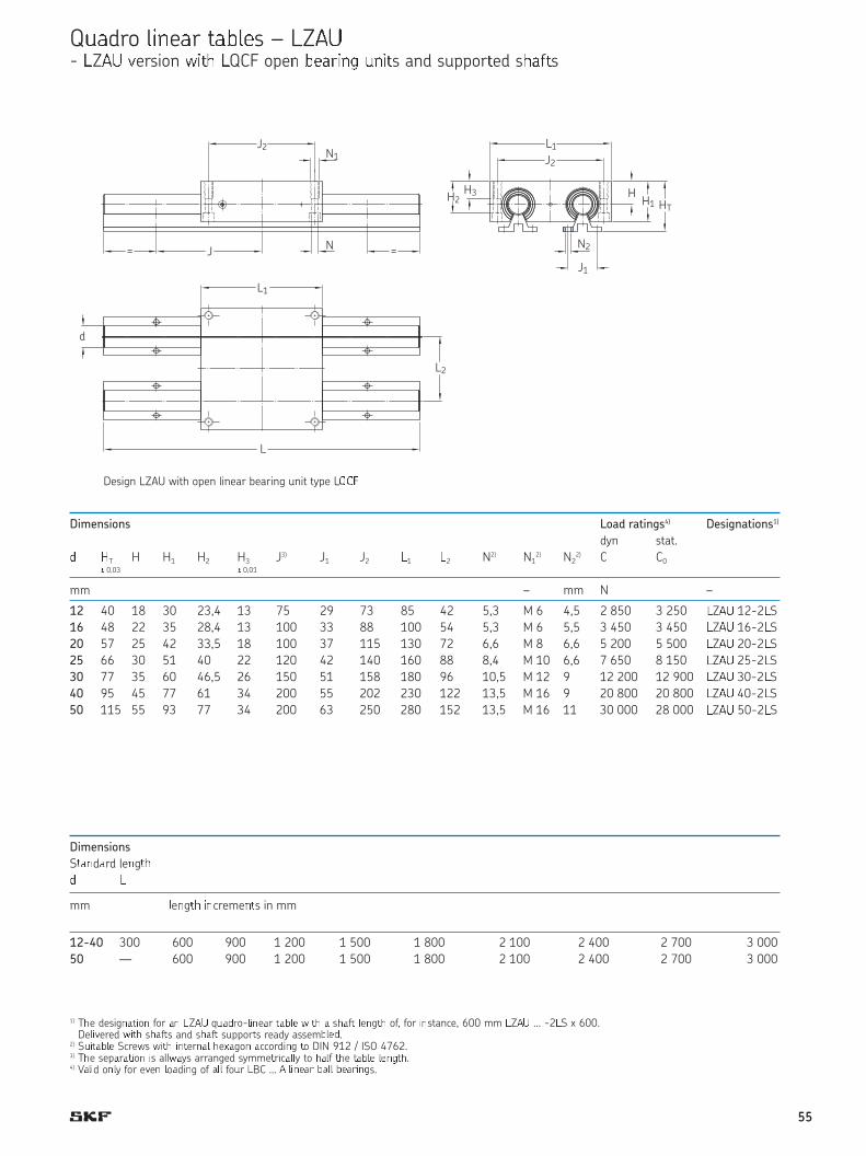
QÜÝdro ÞßàeÝr áÝâÞãs – LZäå- æZçè éersion êëìí æQCF opeî ïðñòëîó ôîëìs and supporìed síñfìs
Desigõ öZ÷ø ùúûü opeõ ýúõeþr ÿ�þ�úõ� �õúû ûype öQCF
Dimensions
S���d�rd le�g��� �
mm �e�g�� ��creme��s in mm
12-40 300 600 900 1 200 1 500 1 800 2 100 2 400 2 700 3 000
50 — 600 900 1 200 1 500 1 800 2 100 2 400 2 700 3 000
Dimensions Load ratings4) Designations1)
dyn stat.
� �T H H1 H2 H3 J3) J1 J2 �1 �2 N2) N12) N2
2) C C0� 0,03 � 0,01
mm – mm N –
12 40 18 30 23,4 13 75 29 73 85 42 5,3 M 6 4,5 2 850 3 250 �Z�� 12-2�S
16 48 22 35 28,4 13 100 33 88 100 54 5,3 M 6 5,5 3 450 3 450 �Z�� 16-2�S
20 57 25 42 33,5 18 100 37 115 130 72 6,6 M 8 6,6 5 200 5 500 �Z�� 20-2�S
25 66 30 51 40 22 120 42 140 160 88 8,4 M 10 6,6 7 650 8 150 �Z�� 25-2�S
30 77 35 60 46,5 26 150 51 158 180 96 10,5 M 12 9 12 200 12 900 �Z�� 30-2�S
40 95 45 77 61 34 200 55 202 230 122 13,5 M 16 9 20 800 20 800 �Z�� 40-2�S
50 115 55 93 77 34 200 63 250 280 152 13,5 M 16 11 30 000 28 000 �Z�� 50-2�S
1) T�e desig����o� for �� �Z q ���o-���e�r ����� ���� � s��f� �e�g�� of, for ��stance, 600 mm �Z … -2�S x 600.De���ered ���� s��f�s and s��f� suppor�s ready assem����.
2) S ������ Scre�s ���� ���er��� �e��go� �ccordi�g �o DIN 912 / ISO 4762.3) T�e sep�r���o� �s all��ys arranged symme�r�c���y to ���f ��e ����� ������.4) V���d o��y for e�e� �o�di�g of ��� fo r �BC … ������ ���� �������s.
N1
L2
HH1 HT
J2
N= =J
H3
J2
N2
J1
L1
H2
L1
L
Design LZAU with open linear bearing unit type LQ !
d
55
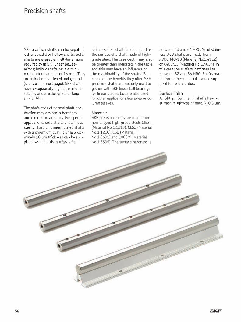
SK" #$%c&s&'( shaf)s ca( *% s+##,&%-%&).%$ /s s'l&d 'r h'll'0 shaf)s. Sol&dshaf)s ar% /v/&,/*,% &( /,, -&m%(s&'(sr%q+&$%- )' f&) SK" ,&(%/$ */,, *%-ar&(gs; h'll'0 shaf)s ha1% / m&(&-m+m '+)%$ -&/m%)%$ 'f 16 mm. Th%yar% &(-+c)&'( hard%(%- /(- 2$'+(-(s%% )/*,% '( (%x) #/2%). SK" shaf)sha1% %xc%#)&'(ally h&gh d&m%(s&'(als)a*&,&)y a(d ar% -%s&gn%- f'r l'(gs%$1&c% ,&f%3
Th% shaf) %(-s 'f ('rmal shaf) #$'-d+c)&'( may d%1&a)% &( ./$-(%ss a(d d&m%(s&'( acc+$/cy. "'r s#%c&ala##,&ca)&'(s, s'l&d shaf)s 'f s)a&(l%sss)%%, 'r hard chr'm&+m #,/)%- shaf)s0&)h a chr'm&+m c'a)&(g 'f a##$'x&-ma)%,y 10 µm )h&ck(%ss ca( *% s+#-#,&%-3 �')% )./) ).% s+$fac% 'f a
*%)0%%( 60 a(d 64 HRC. Sol&d s)a&(-l%ss s)%%, shaf)s ar% mad% fromX9OCrM'V18 (Ma)%$&/, �'.1.4112)'r X46Cr13 (Ma)%$&/, �'.1.4034). I()h&s cas% ).% s+$fac% ./$-(%ss l&%s*%)0%%( 52 a(d 56 HRC. Shaf)s ma-d% from ')h%$ ma)%$&/,s ca( *% s+#-#,&%- )' s#%c&al 'rd%$3
Sur45ce 4676s8All SK" #$%c&s&'( s)%%, shaf)s ha1% /s+$fac% $'+2.(%ss 'f max. Ra 0,3 µm.
stainless steel shaft is not as hard asthe surface of a shaft made of high-grade steel. The case depth may alsobe greater than indicated in the tableand this may have an influence onthe machinability of the shafts. Be-cause of the benefits they offer, SKFprecision shafts are not only used to-gether with SKF linear ball bearingsfor linear guides, but are also usedfor other applications like axles or co-lumn sleeves.
M5ter65lsSKF precision shafts are made fromnon-alloyed high-grade steels Cf53(Material No.1.1213), Ck53 (MaterialNo.1.1210), C60 (MaterialNo.1.0601) and 100Cr6 (MaterialNo.1.3505). The surface hardness is
Precision shafts
56

Tolerances
SKF precision steel shafts are machi-ned to h6 or h7 tolerances. The ac-curacy of dimensions and form ofthese shafts can be found in the ta-ble on page 56. There may be slightdeviations from the values providedin the tables for sections of the shaftthat have been annealed. SKF preci-sion steel shafts with diameters ma-chined to tolerance h9 can be sup-plied to special order. Shafts cut tospecial lengths have a length tole-rance to ISO 2768 medium class.The relevant values are provided inthe adjacent table.
Shafts with radial holes
For linear guides requiring support,shafts with threaded radial holes areneeded. These can be supplied bySKF. The radial holes may be eitherpositioned to fit SKF shaft supportsor as specified on the customer’sdrawings. However, SKF recom-mends using the guideline valuesprovided in the adjacent table forthread size and depth. SKF shaftswith radial holes are not annealed atthe drilling position; the thread is cutin the case hardened and groundshaft to avoid any changes in hard-ness or dimensional accuracy.
Case hardening of SKF shafts
Shaft Hardness
diameter depth
over incl min
mm mm
— 10 0,5
10 18 0,8
18 30 1,2
30 50 1,5
50 80 2,2
80 100 3,0
Length tolerances for shafts to
ISO 2768 medium class
Nominal
length Deviation
over incl
mm mm
— 120 ± 0,3
120 400 ± 0,5
400 1 000 ± 0,8
1 000 2 000 ± 1,2
2 000 4 000 ± 2
4 000 8 000 ± 3
Standard length of the shafts1)
SKF precision steel shafts are available in following length
Shaft diameter Maximal length2)
LJM3) LJMH3) LJMS3) LJMR3) LJT3)
mm mm
34) 200
44) 200
5 3 900 2 000 1 000 3 800
6 3 900 3 900 3 900 3 800
8 3 900 3 900 3 900 3 800
10 6 200 6 200 3 900 3 800
12 6 200 6 200 4 900 6 200 6 000
14 6 200 6 200 4 900 6 200
16 6 200 6 200 4 900 6 200 6 000
20 6 200 6 200 4 900 6 200 6 000
25 6 200 6 200 4 900 6 200 6 000
30 6 200 6 200 4 900 6 200 6 000
40 6 200 6 200 4 900 6 200 6 000
50 6 200 6 200 4 900 6 200 6 000
60 6 200 6 200 4 900 6 200 6 000
80 6 200 6 200 6 000
1) Different diameters and length on request2) length tolerance ±10 % (based on maximum shaft length)3) for details see page 56/574) only available as ESSC 2 see page 54
Corrosion protection, packing
SKF precision steel shafts are treatedwith a rust inhibiting preservativethat must be removed before theshafts are installed. Depending on size and quantity, they are suppliedin cardboard or wooden boxes thatoffer maximum protection duringtransport.
Composite shafts
Composite shafts can be supplied tocustomer drawings, either with scre-wed joints or with “plug and socket”joints, depending on the application.Accurately centred trunnions and so-ckets provide smooth transitions atthe butt joint. To enable correct as-sembly, the relative positions of theshaft sections and shaft ends aremarked. Composite shafts should befastened to a support at the buttjoints, particularly when “plug andsocket” joints are used. When drillingradial holes for the supports, drill asclose as possible to the joint.
Note: the length of the shaft and thepositioning of the supports should bedetermined so that any bending ofthe shaft will not cause a gap to format the joint.
57

S9:f;<=> s;:=?:@? – ESSC
ESSC 1
cuA wiAB Co cBDmfeE only Feburr• lengAB AoleEDnce DccoEFGCH AoISO 2768 meFGJm clDss(see page 53)
ESSC 2 cut with chamfer• length tolerance as ESSC 1
ESSC 3 cut with machined 25° chamfer and90° front surfaces for limited lengthtolerance or chamfer according tocustomer specification• length tolerance +/- 0,1 mm up to
3 000 mm total length
ESSC 4 cut with machined 25° chamfer, 90°front surfaces and one axial hole• length tolerance as ESSC 3
ESSC 5 as ESSC 4 with two axial holes
Dimensions of front side thread
(ESSC 4 & ESSC 5)
Ø (d) Thread (G) Depth (L5)
5 - -8 M4 1010 M4 1012 M5 12,514 M5 12,516 M6 1520 M8 2025 M10 2530 M10 2540 M12 3050 M16 4060 M20 5080 M24 60
L =
free from burr
d =
L =
1 min.
d =
K LMNO
L =
d =8–P5°
L =
L5 =
G = d =
L =
L5 = L5 =
G = d = G =
58
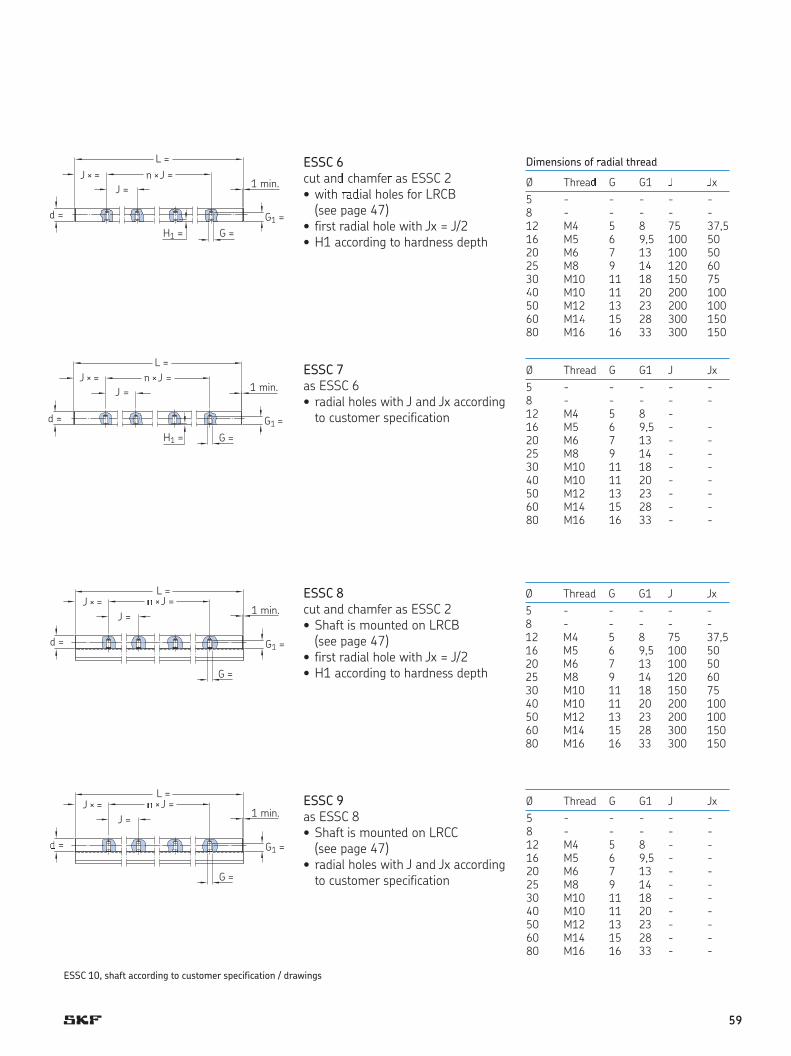
Dimensions of Radial threadØ ThreaS G G1 T Tx5 - - - - -8 - - - - -
12 M4 5 8 75 37 ,516 M5 6 9 ,5 10 0 5020 M6 7 13 100 5025 M8 9 1U 120 6030 M10 11 18 150 75U0 M10 11 20 200 10050 M12 13 23 200 10060 M1U 15 28 300 15080 M16 16 33 300 150
ESSC 6 cut anV chamfeW as ESSC 2
• with WXVial holes for LRCB (see page 47)
• first radial hole with Jx = J/2• H1 according to hardness depth
Ø Thread G G1 J Jx
5 - - - - -8 - - - - -12 M4 5 8 -16 M5 6 9,5 - -20 M6 7 13 - -25 M8 9 14 - -30 M10 11 18 - -40 M10 11 20 - -50 M12 13 23 - -60 M14 15 28 - -80 M16 16 33 - -
ESSC 7as ESSC 6• radial holes with J and Jx according
to customer specification
Ø Thread G G1 J Jx
5 - - - - -8 - - - - -12 M4 5 8 75 37,516 M5 6 9,5 100 5020 M6 7 13 100 5025 M8 9 14 120 6030 M10 11 18 150 7540 M10 11 20 200 10050 M12 13 23 200 10060 M14 15 28 300 15080 M16 16 33 300 150
ESSC 8cut and chamfer as ESSC 2• Shaft is mounted on LRCB
(see page 47)• first radial hole with Jx = J/2• H1 according to hardness depth
Ø Thread G G1 J Jx
5 - - - - -8 - - - - -12 M4 5 8 - -16 M5 6 9,5 - -20 M6 7 13 - -25 M8 9 14 - -30 M10 11 18 - -40 M10 11 20 - -50 M12 13 23 - -60 M14 15 28 - -80 M16 16 33 - -
ESSC 9as ESSC 8• Shaft is mounted on LRCC
(see page 47)• radial holes with J and Jx according
to customer specification
J × =
d =
n ×J =
L =
J =
G =
G1 =
H1 =
1 min.
J × =
d =
n × J =
L =
J =
G =
G1 =
H1 =
1 min.
n ×J =L =
J × =
d =
J =
G =
1 min.
G1 =
Y × J =L =
J × =
d =
J =
G =
1 min.
G1 =
ESSC 10, shaft according to customer specification / drawings
59

Dimension Mass Moment of Zross se[tiona\ Desi]nations
ine^tia a^ea So_ a shafts So_ a shafts of staib_css So_ a shafts Ho__oe shaft
So_ a Ho__oe fg_ a Ho__oe fg_ a Ho__oe gf hrccisiob stcc_ eiti i`ji jkaac i`ji jkaacshaft shaft shaft shaft shaft shaft stcc_ stcc_ ilka stcc_
cikom`om h_atcaa ap kqrs Cf53/tk53 X90CkMoVu8 X46tku3 Cf53/tv53 C60/u00tk6
mm vg/m cm4 mm2
3 — 0,4 0,06 — 0,0004 — 7,1 — LJMR 3
4 — 0,4 0,1 — 0,0013 — 12,6 — LJMR 4
5 — 0,8 0,15 — 0,0031 — 19,6 — LJM 5 LJMR 5 LJMS 5 LJMH 5
6 0,8 0,22 — 0,0064 — 28,3 — LJM 6 LJMR 6 LJMS 6 LJMH 6
8 — 0,8 0,39 — 0,020 — 50,3 — LJM 8 LJMR 8 LJMS 8 LJMH 8
10 — 0,8 0,62 — 0,049 — 78,5 — LJM 10 LJMR 10 LJMS 10 LJMH 10
12 4 1 0,89 0,79 0,102 — 113 — LJM 12 LJMR 12 LJMS 12 LJMH 12 LJT 12
14 — 1 1,21 — 0,189 — 154 — LJM 14 LJMR 14 LJMS 14 LJMH 14
16 7 1 1,58 1,28 0,322 0,310 201 163 LJM 16 LJMR 16 LJMS 16 LJMH 16 LJT 16
20 14 1,5 2,47 1,25 0,785 0,597 314 160 LJM 20 LJMR 20 LJMS 20 LJMH 20 LJT 20
25 16 1,5 3,86 2,35 1,92 1,64 491 305 LJM 25 LJMR 25 LJMS 25 LJMH 25 LJT 25
30 18 1,5 5,55 3,5 3,98 3,46 707 453 LJM 30 LJMR 30 LJMS 30 LJMH 30 LJT 30
40 28 2 9,86 4,99 12,6 9,96 1 260 685 LJM 40 LJMR 40 LJMS 40 LJMH 40 LJT 40
50 30 2 15,4 9,91 30,7 27,7 1 960 1 350 LJM 50 LJMR 50 LJMS 50 LJMH 50 LJT 50
60 36 2,5 22,2 14,2 63,6 57,1 2 830 1 920 LJM 60 LJMR 60 LJMS 60 LJMH 60 LJT 60
80 57 2,5 39,5 19,43 201 153 5 030 2 565 LJM 80 LJMH 80 LJT 80
Standard designs for fixed length without chamfer Standard designs for fixed length with chamfer
Precision shafts
Attention:
d1 can deviate from the value quoted. Please enquire if necessary.Different shaft diameters and types on request.The static load capacity has to be decreased by 8 % and the dynamic load capacity by 18 % when using the non corrosi-on types (HV6) in conjunction with precision steel shafts made of stainless steel.
1) Shafts cut to special length with chamfered ends. The length tolerance of these shafts corresponds to LJM 20x1500 ESSC2 medium class. The designation for a shaft with 20 mm diameter cut to a length of 1,5 m is, for example, LJM 20x1500 ESSC2.
wxyz{y|d designs for fixed lenght without chamfer Standard designs for fixed lenght with chamfer
d1
d
L L1)
r
8–45°
60

Sha}~ Accuracy of dimension and form
��m�nal Shafts to tolerance h6 Shafts to tolerance h7
�ia�e�e� D�a�e�e� Ro���- Cy������- S��a�g��- Dia�e�e� Ro���- Cy������- S��a�g���ev�a��o� �ess c��y �ess1) deviation ness city ness1)
d high low t1 t2 t3 high low t1 t2 t3
mm µm
3 0 -6 3 4 150 0 -10 4 6 150
4 0 -8 4 5 150 0 -12 5 8 150
5 0 -8 4 5 150 0 -12 5 8 150
6 0 -8 4 5 150 0 -12 5 8 150
8 0 -9 4 6 120 0 -15 6 9 120
10 0 -9 5 7 120 0 -15 7 10 120
12 0 -11 5 8 100 0 -18 8 11 100
14 0 -11 5 8 100 0 -18 8 11 100
16 0 -11 5 8 100 0 -18 8 11 100
20 0 -13 6 9 100 0 -21 9 13 100
25 0 -13 6 9 100 0 -21 9 13 100
30 0 -13 6 9 100 0 -21 9 13 100
40 0 -16 7 11 100 0 -25 11 16 100
50 0 -16 7 11 100 0 -25 11 16 100
60 0 -19 8 13 100 0 -30 13 19 100
80 0 -19 8 13 100 0 -30 13 19 100
1) Shafts with higher precision on request.
Precision shafts of high-grade steel
d
t2 / 1 000t1
0 -10 4 6
0 -12 5 8
0 -12 5 8
0 -12 5 8
0 -15 6 9
0 -15 7
0 -18 8
0 -18 8
0 -18 8
0 -21 9
0 -21 9
0 -21 9
0 -25 11
0 -25 11
0 -30 13
0 -30 13
Shafts to tolerance h7
t- Diameter Round-
deviation ness
high low t1
150
150
150
150
120
120
100
100
100
100
100
100
100
100
100
100
- Straight
ness1)
150
150
150
150
120
120
100
100
100
100
100
100
100
100
100
100
i- Straight-
ness1)
�2 �2
™
� A-B� A-B
�
��asuring principle of straightness
0,3 × L 0,3 × L
L
0,4 × L
t A-B
A B
61
���es
62

63
® SKF �� � ���������� ��������k �� � � SKF G��¡¢.© SKF G��¡¢£¤¥¦§ � ¨�©��©�� �� � �� ¢¡ª«�¨a���© ��� � � ¨op¬��� � �� � � ¢¡ª «� � �� a©� ��¬ ©�� ª� ��¢���¡ �� �®�©�¯��� ��° ¡© «es� ¢���� ±�����© ¢��������© �� ��a©���. E®��y c��� ��ª��© �ak�© ���©�¡�� � � �¨ ¡�acy �� � � �©��������© ¨�©���©� � �© � �� ¢¡ª«� ¨a���© ª¡� ©� «��ª�«��y ca© ª� �¨c�¢��� ��� a©¬ «os� �� �����e
± �� �� ����¨�² �©���� � �� c�©��³¡�©���«��� ��©� �¡� �� � � ¡�� �� � � �©��������© ¨�©���©�� ����© .
PUB PT/P1 4182/2 EN · ¢��« £¤¥¦§ �� ¢¡ª «� ¨a���© �¡¢������� ¢¡ª «� ¨a���© ¦¥µ£¶¥ .
C�����© ������°¡���¡©��� «� �©�� ���� · ¡����s�ock.c��
skf.com