LINE CUTTING MAG SURV RPT SAVARD TWP - … · Skead Holdings Ltd. Total Reid Magnetometer Survey...
15
LARDER GEOPHYSICS L TD. 2 0 3259 14579 Government Roa< Larder Lake, Ontari< POK 1 LO, Canad, Phone (705) 643-112: Fax (705) 643-219" SKEAD HOLDINGS LTD . Magnetometer SUlVey Over the SAVARD I AIM #3006666 PROPERTY Savard Township, Ontario RECE VED JUL U 5 Z006 GEOSCIENCE ASSESSMENT OFFICE
-
Upload
truonghanh -
Category
Documents
-
view
218 -
download
0
Transcript of LINE CUTTING MAG SURV RPT SAVARD TWP - … · Skead Holdings Ltd. Total Reid Magnetometer Survey...

LARDER GEOPHYSICS LTD.
2 0 3259
14579 Government Roa<
Larder Lake, Ontari< POK 1 LO, Canad,
Phone (705) 643-112:
Fax (705) 643-219"
SKEAD HOLDINGS LTD.
Magnetometer SUlVey Over the
SAVARD I AIM #3006666 PROPERTY
Savard Township, Ontario
RECE VED JUL U 5 Z006
~ GEOSCIENCE ASSESSMENT
OFFICE
Skead Holdings Ltd. Total Reid Magnetometer Survey Savard Claim #3006666
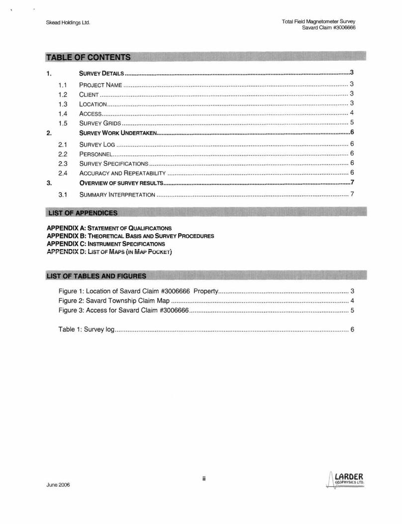
fABLE OF CONTENTS
1. SURVEY DETAILS ........................................................................................................................................ 3
1.1 PROJECT NAME ..... ..... ............................ . ..... .. ....... ....................................................................... 3
1.2 CLIENT ...................................... ......... ... .... ........ ....... ...... .. ........ ............... ... .... ...... ..... ..... .. ........ .. .. 3
1.3 LOCATION ........................... ............... .. ............... . ................................... ... .. ....... . ......................... 3
1.4 ACCESS .... ... ..... ... ... ................. ........................................................ ........ . .... . ............................... 4
1.5 SURVEY GRIDS ....... .......... ..... ... .... ... ...................... .. . ........... .... ...... ... .. ... ....................................... 5
2. SURVEY WORK UNDERTAKEN ..................................................................................................................... 6
2.1 SURVEY LOG ... . ............. . ......................... .. ...................... ........ ......... ............. ... .................. ...... .... 6
2.2 PERSONNEL. .. ......................................... . ......... ..... ... ... ............................... ........ ............ . ............. 6
2.3 SURVEY SPECiFiCATIONS .................. ........ ... .... .. .... . ....... ............ ....... ............................................ 6
2.4 ACCURACY AND REPEATABILITY .... ... ...... ............ .. .......................... ....... . ...................... .... ............. 6
3. OVERVIEW OF SURVEY RESULTS ................................................................................................................. 7
3.1 SUMMARY INTERPRETATION ...... ................................................. ....................... ..... .... ............ ....... 7
NDICES
APPENDIX A: STATEMENT OF QUALIFICA1l0NS
APPENDIX B: THEORETICAL BASIS AND SURVEY PROCEDURES
APPENDIX C: INSTRUMENT SPECIFICA1l0NS
APPEt.:o;X D: LiST OF MAPS (iN iviAP POCKEij
USTOF TABL
Figure 1: Location of Savard Claim #3006666 Property ... ..................... ............ .... ............... .. .... ...... ..... 3
Figure 2: Savard Township Claim Map ............... ......... ....... ... .. ................................... ... .............. .. ........ 4
Figure 3: Access for Savard Claim #3006666 ..... ... ............ .. .. ......... ... ..... .. .. .... ....................................... 5
Table 1: Survey log ......... ................ .... ............................... ....... ........................ .. ... .. ..... .......................... 6
ii LARDER June 2006 GfOI'HVSles LTD.
1.1 PROJECT NAME
This project is known as CLAIM #3006666 property.
1.2 CLIENT
SKEAD HOLDINGS LTD.
28 Ford St. Sault Ste. Marie, Ontario P6A 4N4
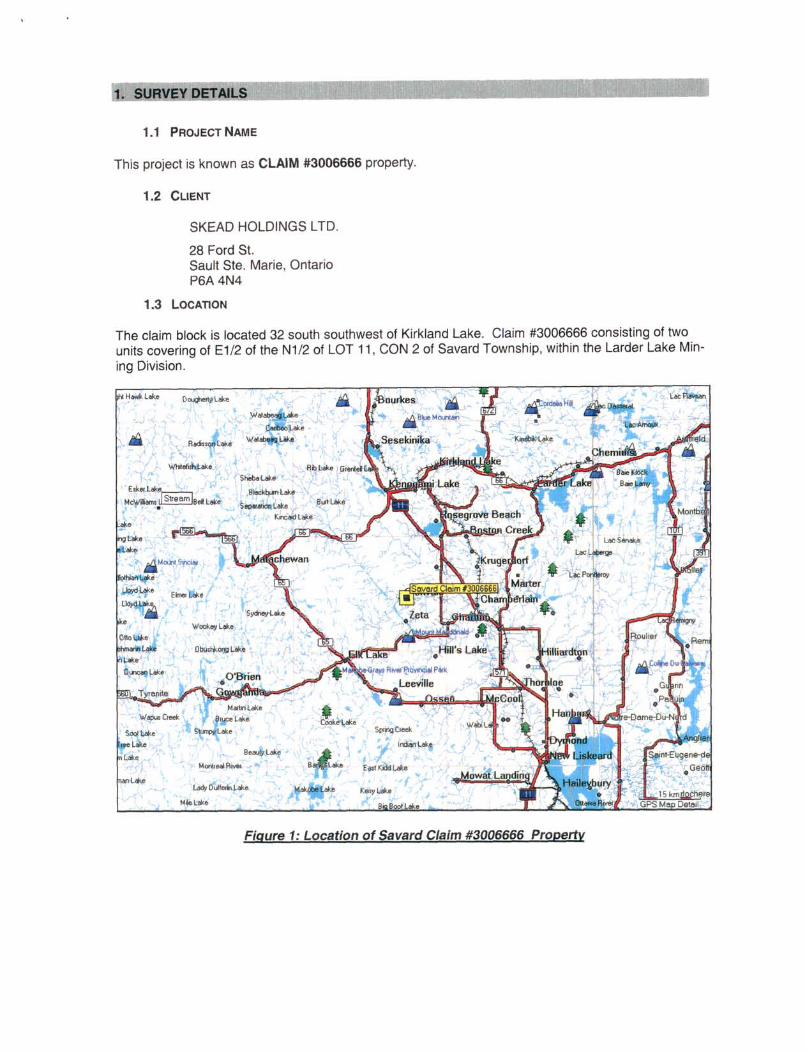
1.3 LOCATION
The claim block is located 32 south southwest of Kirkland Lake. Claim #3006666 consisting of two units covering of E1/2 of the N1/2 of LOT 11 , CON 2 of Savard Township, within the Larder Lake Mining Division.
HoWkLok •
• ).. "..., B.~~~ j ., McriJ'" A...., ., T •
... t.., ....
Figure 1: Location of Savard Claim #3006666 Property
Skead Holdings Ltd.
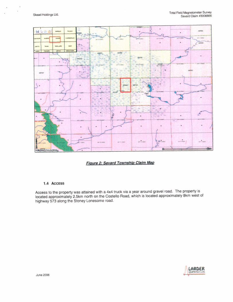
1.4 ACCESS
Figure 2: Savard Township Claim Map
Total Field Magnetometer Survey Savard Claim #3006666
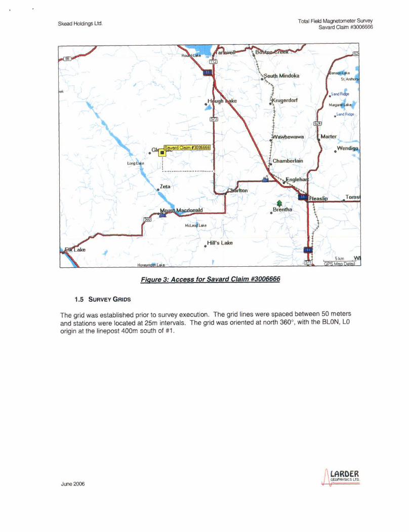
Access to the property was attained with a 4x4 truck via a year around gravel road. The property is located approximately 2.5km north on the Costello Road, which is located approximately Bkm west of highway 573 along the Stoney Lonesome road.
LARDER June 2006
GEOI'IIVSltS LTD.
Skead Holdings Ltd.
, ..J
1.5 SURVEY GRIDS
<"
GI Savard Oaim 13006666 • . ' . - I
• HiII's Lake
Hone ,
~., ;,
-B~entha . -....
Figure 3: Access for Savard Claim #3006666
Total Field Magnetometer Survey Savard Claim #3006666
The grid was established prior to survey execution. The grid lines were spaced between 50 meters and stations were located at 25m intervals. The grid was oriented at north 360°, with the BLON, LO origin at the linepost 400m south of #1.
LARDER June 2006 Gf04'HVSICS lTD.
8kead Holdings Ltd.
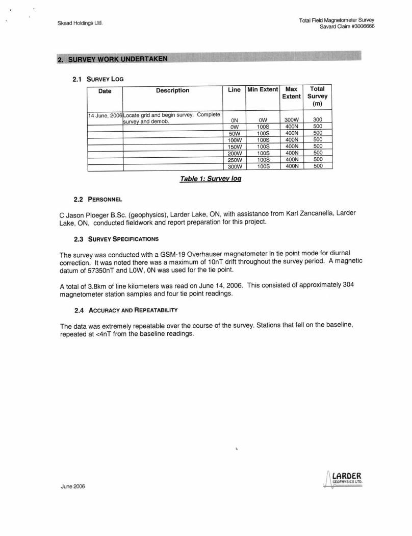
2.1 SURVEY LOG
Date Description Line
14 June, 2006 Locate grid and begin survey. Complete survey and demob. ON
OW SOW 100W 150W 200W 250W 300W
Table 1: Survey log
2.2 PERSONNEL
Min Extent
OW 1008 1008 1008 1008 1008 1008 1008
Max
Total Reid Magnetometer 8urvey Savard Claim #3006666
Total Extent Survey
(m)
300W 300 400N 500 400N 500 400N 500 400N 500 400N 500 400N 500 400N 500
C Jason Ploeger B.Sc. (geophysics), Larder Lake, ON, with assistance from Karl Zancanella, Larder Lake, ON, conducted fieldwork and report preparation for this project.
2.3 SURVEY SPECIFICATIONS
The SLiiV6Y 'vvas conducted \Nith a GS~.~-19 OverhaL!ser magnetometer in tie point mode for diurnal correction. It was noted there was a maximum of 10nT drift throughout the survey period. A magnetic datum of 57350nT and LOW, ON was used for the tie point.
A total of 3.8km of line kilometers was read on June 14, 2006. This consisted of approximately 304 magnetometer station samples and four tie point readings .
2.4 ACCURACY AND REPEATABILITY
The data was extremely repeatable over the course of the survey. Stations that fell on the baseline, repeated at <4nT from the baseline readings.
\
LARDER June 2006 GfOPHVSfCSlTO.
Skead Holdings Ltd.
3.1 SUMMARY INTERPRETATION
Total Field Magnetometer Survey Savard Claim #3006666
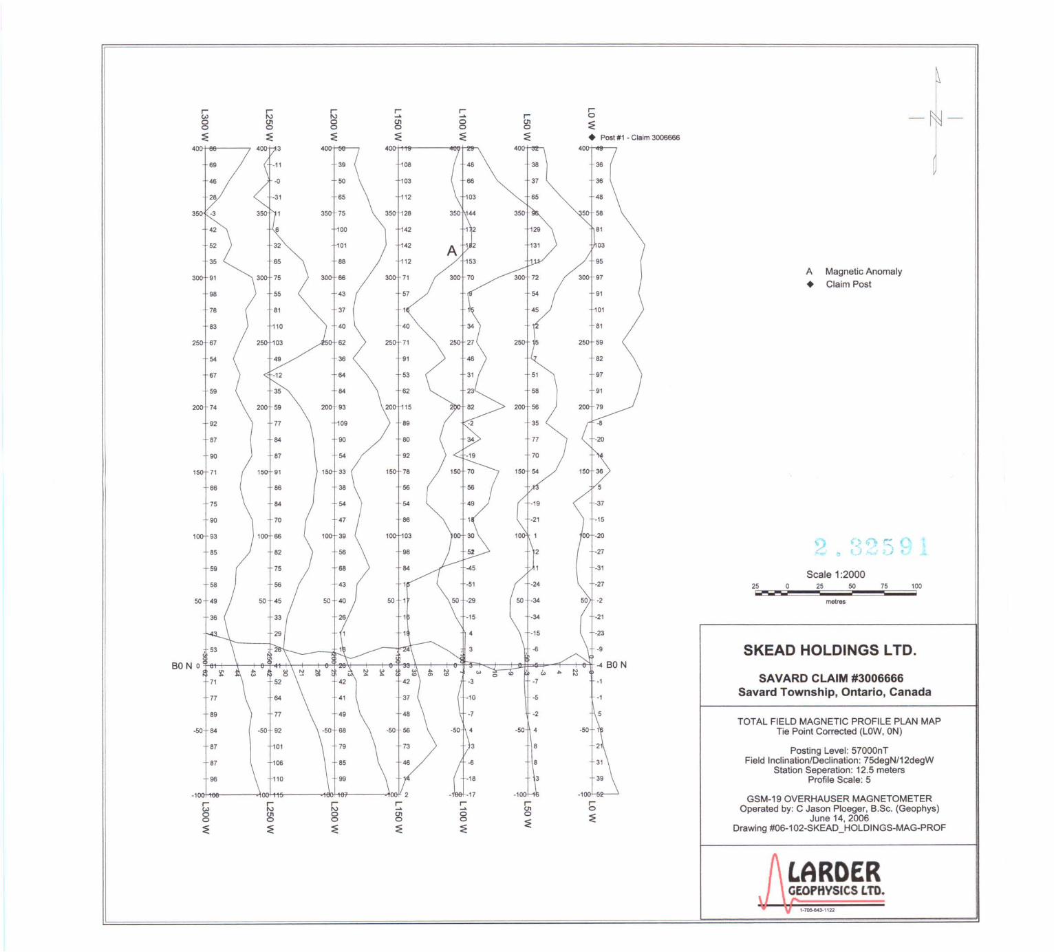
Numerous minor magnetic fluctuations occur throughout the survey area. Most of these may result from fracturing and small lenses within the underlying granite.
There is one notable anomaly on this project and that has been labeled as anomaly A. This appears centered over line 100W near 300N. This may represents an inconsistency within the underlying mapped granite. With the small grid it is difficult to determine whether this anomaly is constrained or part of a larger linear anomaly.
A second anomaly appears within the survey area. This appears to be a more linear anomaly trending in a NNE direction. This may represent a dyke or faulting structure.
LARDER June 2006 GEOftlVSICS lTO.
Skead Holdings Ltd.
STATEMENT OF QUALIFICATIONS
I, C. Jason Ploeger, hereby declare that:
Total Field Magnetometer Survey Savard Claim #3006666
1. I am a geophysicist (non-professional) with residence in Larder Lake, Ontario and am presently employed as president of Larder Geophysics Ltd. of Larder Lake, Ontario.
2. I graduated with a Bachelor of Science degree in geophysics from the University of Western Ontario, in London Ontario, in 1999.
3. I have practiced my profession continuously since graduation in Africa, Bulgaria, Canada, Mexico and Mongolia.
4. I am a member of the Ontario Prospectors Association.
5. I have no interest, nor do I expect to receive any interest in the properties or securities of SKEAD HOLDINGS LTD.
6. I am responsible for all data collection , the final processing and validation of the survey results and the compilation of the presentation of this report. The statements made in this report represent my professional opinion based on my consideration of the information available to me at the time of writing this report.
June 2006
Larder Lake, Oi~ June 2006
c. Ja,b';';::-1geOPhY';CSl President of Larder Geophysics Ltd.
LARDER ClOPHV5IC$ lTD.
Skead Holdings Ltd.
APPENDIXB
THEORETICAL BASIS AND SURVEY PROCEDURES
TOTAL FIELD MAGNETIC SURVEY
Total Field Magnetometer Survey Savard Claim #3006666
Base station corrected Total Field Magnetic surveying is conducted using at least two synchronized magnetometers of identical type. One magnetometer unit is set in a fixed position in a region of stable geomagnetic gradient, and away from possible cultural effects (i.e. moving vehicles) to monitor and correct for daily diurnal drift. This magnetometer, given the term 'base station', stores the time, date and total field measurement at fixed time intervals over the survey day. The second, remote mobile unit stores the coordinates, time, date, and the total field measurements simultaneously. The procedure consists of taking total magnetic measurements of the Earth's field at stations, along individual profiles, including Tie and Base lines. A 2 meter staff is used to mount the sensor, in order to optimally minimize localized near-surface geologic noise. At the end of a survey day, the mobile and base-station units are linked, via RS-232 ports, for diurnal drift and other magnetic activity (ionospheric and sferic) corrections using internal software.
For the gradiometer application , two identical sensors are mounted vertically at the ends of a rigid fiberglass tube. The centers of the coils are spaced a fixed distance apart (0.5 to 1.0m). The two coils are then read simultaneously, which alleviates the need to correct the gradient readings for diurnal variations, to measure the gradient of the total magnetic field .
LARDER June 2006 GfOl'HVSlCS UO.
Skead Holdings Ltd.
APPENDIXC
INSTRUMENT SPECIFICATIONS
3.1.1 Introduction
Total Field Magnetometer Survey Savard Claim #3006666
The GSM-19 v7.0 Overhauser instrument is the total field magnetometer / gradiometer of choice in today's earth science environment -representing a unique blend of physics, data quality, operational efficiency, system design and options that clearly differentiate it from other quantum magnetometers.
With data quality exceeding standard proton precession and comparable to costlier optically pumped cesium units, the GSM-19 is a standard (or emerging standard) in many fields.
Taking Advantage of a "Quirk" of Physics
Overhauser effect magnetometers are essentially proton precession devices except that they produce an orderof magnitude greater sensitivity. These ·supercharged" quantum magnetometers also deliver high absolute accuracy, rapid cycling (up to 5 readings / second), and exceptionally low power consumption .
The Overhauser effect occurs when a special liquid (with unpaired electrons) is combined with hydrogen atoms and then exposed to secondary polarization from a radio frequency (RF) magnetic field. The unpaired electrons transfer their stronger polarization to hydrogen atoms, thereby generating a strong precession signal-- that is ideal for very high-sensitivity total field measurement. In comparison with proton precession methods, RF signal generation also keeps power consumption to an absolute minimum and reduces noise (i.e. generating RF frequencies are well out of the bandwidth of the precession signal) .
In addition , polarization and signal measurement can occur simultaneously - which enables faster, sequential measurements. This, in turn, facilitates advanced statistical averaging over the sampling period and/or increased cycling rates (i.e. sampling speeds).
The unique Overhauser unit blends physics, data quality, operational efficiency, system design and options into an instrumentation package that ... exceeds proton precession and matches costlier optically pumped cesium capabilities.
And the latest v7.0 technology up-grades provide even more value, including:
- Data export in standard XYZ (i.e. line-oriented) format for easy use in standard commercial software programs - Programmable export format for full control over output - GPS elevation values provide input for geophysical modeling - <1 .5m standard GPS for high- resolution surveying - Enhanced GPS positioning resolution - Multi-sensor capability for advanced surveys to resolve target geometry - Picket marketing / annotation for capturing related surveying information on the go.
Maximizing Your Data Quality with the GSM-19
Data quality is a function of five key parameters that have been taken into consideration carefully in the design of the GSM-19. These include sensitivity, resolution , absolute accuracy, sampling rates and gradient tolerance.
Sensitivity is a measure of the signal-to noise ratio of the measuring device and reflects both the underlying physics and electronic design. The physics of the Overhauser effect improves sensitivity by an order of magni-
I LARDER June 2006 CfOl'IIV$ltS LTG.
Skead Holdings Ltd. Total Field Magnetometer Survey Savard Claim #3006666
tude over conventional proton precession devices. Electronic enhancements, such as high-precision precession frequency counters enhance sensitivity by 25% over previous versions.
The result is high quality data with sensitivities of 0.015 nT / vHz or better. This sensitivity is also the same order-of magnitude as costlier optically pumped cesium systems ..
Resolution is a measure of the smallest number that can be displayed on the instrument (or transmitted via the download process). The Overhauser magnetometer displays 7 digits which includes 5 digits, decimal point and two decimal digits.
This level of resolution translates into well-defined, characteristic anomalies; improved visual display; and enhanced numerical data for processing and modeling.
Absolute accuracy reflects the closeness to the "real value" of the magnetic field -- represented by repeatability of readings either at stations or between different sensors. With an absolute accuracy of +/- 0.1 nT, the GSM-19 delivers repeatable station-to-station results that are reflected in high quality total field results.
Similarly, the system is ideal for gradient installations (readings between different sensors do not differ by more than +/- 0.1 nT) -- maintaining the same high standard of repeatability.
The GSM-19 gradiometer data are consistently low in noise and representative of the geologic environment under investigation.
Sampling rates are defined as the fastest speed at which the system can acquire data. This is a particularly important parameter because high sampling rates ensure accurate spatial resolution of anomalies and increase survey efficiency.
The GSM-19 Overhauser system is configured for t ... ,;o "measurement modes" or maximum sampling rates -"Standard" (3 seconds / reading), and"Walking" (0.2 seconds / reading)These sampling rates make the GSM-19 a truly versatile system forall ground applications (including vehicle-borne applications).
Gradient tolerance represents the ability to obtain reliable measurements in the presence of extreme magnetic field variations. GSM-19 gradient tolerance is maintained through internal signal counting algorithms, sensor design and Overhauser physics. For example, the Overhauser effect produces high amplitude, long-duration signals that facilitate measurement in high gradients.
The system's tolerance (10,000 nT / meter) makes it ideal for many challenging environments -- such as highly magnetic rocks in mineral exploration applications, or near cultural objects in environmental, UXO or archeological applications.
GSM-19W I WG "Walking" Magnetometer I Gradiometer Option
The GSM-19 was the first magnetometer to incorporate the innovative "Walking" option which enables the acquisition of nearly continuous data on survey lines. Since its introduction, the GSM-19W / GSM-19WG have become one of the most popular magnetic instruments in the world.
Similar to an airborne survey in principle, the system records data at discrete time intervals (up to 5 readings per second) as the instrument is carried along the line.
At each survey picket (fiducial), the operator touches a designated key. The system automatically assigns a picket coordinate to the reading and linearly interpolates the coordinates of all intervening readings (following survey completion during post-processing).
A main benefit is that the high sample density improves definition of geologie structures and other targets (UXO,
LARDER June 2006
GEotHYSICS lTO.
"'F
Skead Holdings Ltd.
archeological relics, drums, etc.).
Total Field Magnetometer Survey Savard Claim #3006666
It also increases survey efficiency because the operator can record data almost continuously. Another productivity feature is the instantaneous recording of data at pickets. This is a basic difference between the "Walking" version and the GSM-19 / GSM-19G (the "Standard" mode version which requires 3 seconds to obtain a reading each time the measurement key is pressed). GSM-19 "Hands-Free" Backpack Option The "Walking" Magnetometer and Gradiometer can be configured with an optional backpack-supported sensor. The backpack is uniquely constructed -permitting measurement of total field or gradient with both hands free. This option provides greater versatility and flexibility, which is particularly valuable for high-productivity surveys or in rough terrain.
More About the Overhauser System
In a standard Proton magnetometer, current is passed through a coil wound around a sensor containing a hydrogenrich fluid. The auxiliary field created by the coil (> 100 Gauss) polarizes the protons in the liquid to a higher thermal equilibrium.
When the current, and hence the field, is terminated, polarized protons precess in the Earth's field and decay exponentially until they return to steady state. This process generates precession signals that can be measured as described below.
Overhauser magnetometers use a more efficient method that combines electron proton coupling and an electron-rich liquid (containing unbound electrons in a solvent containing a free radical). An RF magnetic field -- that corresponds to a specific energy level transition -- stimulates the unbound electrons.
Instead of releasing this energy as emitted radiation, the unbound electrons transfer it to the protons in the solvent. The resulting polarization is much larger, leading to stronger precession signals.
Both Overhauser and proton precession, measure the scalar value of the magnetic field based on the proportionality of precession frequency and magnetic flux density (which is linear and known to a high degree of accuracy). Measurement quality is also calculated using signal amplitude and its decay characteristics. Values are averaged over the sampling period and recorded.
With minor modifications (Le. addition of a small auxiliary magnetic flux density while polarizing), it can also be adapted for high sensitivity readings in fields less than 20,000 nT (ex. for equatorial work).
Key System Components
Key components that differentiate the GSM-19 from other systems on the market include the sensor and data acquisition console. Specifications for components are provided on the right side of this page.
Sensor Technology
Overhauser sensors represent a proprietary innovation that combines advances in electronics design and quantum magnetometer chemistry.
Electronically, the detection assembly includes dual pick-up coils connected in series opposition to suppress farsource electrical interference, such as atmospheric noise. Chemically, the sensor head houses a proprietary hydrogen-rich liquid solvent with free electrons (free radicals) added to increase the signal intensity under RF polarization.
From a physical perspective, the sensor is a small size, light-weight assembly that houses the Overhauser detection system and fluid. A rugged plastic housing protects the internal components during operation and transport.
LARDER June 2006 GfOl'IIVSl(S lTD.
I if
Skead Holdings ltd. Total Field Magnetometer Survey Savard Claim #3006666
All sensor components are designed from carefully screened non-magnetic materials to assist in maximization of signal-to-noise. Heading errors are also minimized by ensuring that there are no magnetic inclusions or other defects that could result in variable readings for different orientations of the sensor.
Optional omni-directional sensors are available for operating in regions where the magnetic field is nearhorizontal (Le. equatorial regions). These sensors maximize signal strength regardless of field direction.
Console Technology
Console technology comprises an external keypad / display interface with internal firmware for frequency counting, system control and data storage / retrieval. For operator convenience, the display provides both monochrome text as well as real-time profile data with an easy to use interactive menu for performing all survey functions.
The firmware provides the convenience of upgrades over the Internet via its software. The benefit is that instrumentation can be enhanced with the latest technology without returning the system to us -- resulting in both timely implementation of updates and reduced shipping I servicing costs.
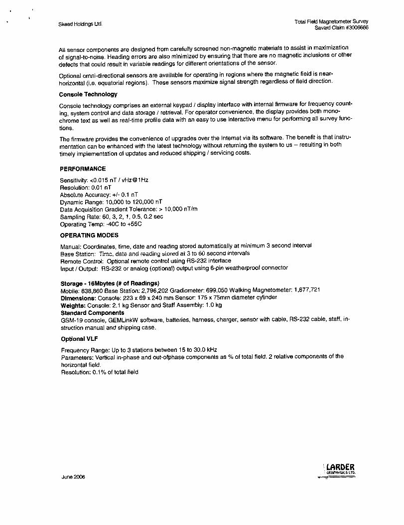
PERFORMANCE
Sensitivity: <0.015 nT I vHz@1Hz Resolution: 0.01 nT Absolute Accuracy: +/- 0.1 nT Dynamic Range: 10,000 to 120,000 nT Data Acquisition Gradient Tolerance: > 10,000 nT/m Sampling Rate: 60, 3, 2. 1. 0.5, 0.2 sec Operating Temp: -40C to +55C
OPERATING MODES
Manual: Coordinates, time, date and reading stored automatically at minimum 3 second interval Base Station: Time, date and reading siorea at 3 to 60 second intervals Remote Control: Optional remote control using RS-232 interface Input IOutput: RS-232 or analog (optional) output using 6-pin weatherproof connector
Storage -16Mbytes (# of Readings) Mobile: 838,860 Base Station: 2,796,202 Gradiometer: 699,050 Walking Magnetometer: 1,677.721 Dimensions: Console: 223 x 69 x 240 mm Sensor: 175 x 75mm diameter cylinder Weights: Console: 2.1 kg Sensor and Staff Assembly: 1.0 kg Standard Components GSM-19 console, GEMLinkW software, batteries, harness, charger, sensor with cable, RS-232 cable, staff, instruction manual and shipping case.
Optional VLF
Frequency Range: Up to 3 stations between 15 to 30.0 kHz Parameters: Vertical in-phase and out-ofphase components as % of total field. 2 relative components of the horizontal field. Resolution: 0.1 % of total field
June 2006 .. LARDER . G£OVIIVSlCS LTD. tl
. ' .. " . Skead Holdings Ltd.
APPENDIXD
LIST OF MAPS (IN MAP POCKET)
Posted profiled TFM plan map (1 :1 000)
1) #06-102-SKEAD_HOLDINGS-MAG-PROF
TOTAL MAPS=1
June 2006
Total Field Magnetometer Survey Savard Claim #3006666
LARDER CEOI'tlVSICSlTIl.
r r r r r r w N N .... .... r 0 0 U'I 0 U'I 0 U'I :E 0 0 0 0 0 0
:E :E :E :E :E :E • Post #1 - Claim 3006666
40 40
39 08
50 03
65 12
35 75 28
42 100 142
52 101 142 03
35 88 112
3 91 66 A Magnetic Anomaly
• Claim Post 98 43
78 37 01
83 40
25 67
54 36
67 64
59 84
20 74
92 77 09 35
87 84
90 87
15 71 15 91
66 86 56
75 84 54
90 70 86
10 93 10 66
~ () t;";7 ,~ t 85 82 ': ) 4-. ~ ';. )
59 75 68 Scale 1 :2000
58 56 43 25 0 25 50 75 100 ----- I
50 49 50 45 50 -34 metres
-34
-15
-6 SKEAD HOLDINGS LTD. BO No
'" 0 <0 W ~
-7 SAVARD CLAIM #3006666
77 37 -5 Savard Township, Ontario, Canada
89 48 -2 TOTAL FIELD MAGNETIC PROFILE PLAN MAP
-50 84 -50 92 -50 56 -50 4 Tie Point Corrected (LOW. ON)
87 101 8 Posting Level: 57000nT
87 106 8 Field Inclination/Declination: 75degN/12degW Station Seperation: 12.5 meters
96 110 3 Profile Scale: 5
-1 0 -1 -10 GSM-19 OVERHAUSER MAGNETOMETER r ~ r r r r r w N .... .... 01 0 Operated by: C Jason Ploeger, B.Sc. (Geophys)
0 U'I 0 01 0 0 ~ 0 0 0 0 0 :E June 14. 2006
:E :E ~ ~ :E Drawing #06-102-SKEAD _HOLDINGS-MAG-PROF
LARDER GEOPHVSICS LTD.
1-705-643-1122


![Darren Lomman Natalie Skead [Keynote Speaker]](https://static.fdocuments.in/doc/165x107/61abb2dc67e961637c150fd5/darren-lomman-natalie-skead-keynote-speaker.jpg)