Line A: Common Occupational Skills Competencies A … · HEAVY MECHANICAL TRADES ˜ FOUNDATION /...
366
HEAVY MECHANICAL TRADES FOUNDATION / LEVEL 1 Line A: Common Occupational Skills Competencies A-14 to A-17
Transcript of Line A: Common Occupational Skills Competencies A … · HEAVY MECHANICAL TRADES ˜ FOUNDATION /...

HEAVY MECHANICAL TRADESFOUNDATION / LEVEL 1
Line A: Common Occupational Skills Competencies A-14 to A-17

OrderingCrown Publications, Queen’s PrinterPO Box 9452 Stn Prov Govt563 Superior St. 3rd Flr Victoria, B.C. V8W 9V7Phone: 1 800 663-6105Fax: 250 387-1120Email: [email protected]: www.crownpub.bc.ca
© 2013, 2016 by Industry Training Authority
This publication may not be reproduced in any form without permission by the Industry Training Authority.
Contact Director, Crown Publications, Queen’s Printer at 250 356-6876.
AcknowledgmentsHeavy Mechanical Trades Project Working Group Writers: Lloyd Babcock, Bob Glover, Terry Lockhart, Roger YoungReviewers: Brian Haugen, Rene Tremblay, Paul Mottershead, Mark Scorah, Rick Cyr, Lloyd Babcock, Terry LockhartEditor: Greg Aleknevicus
Open School BCProject Manager: Solvig Norman, Christina Teskey (revisions) Production Technicians: Sharon Barker, Beverly Carstensen, Dennis EvansArt Coordination: Dennis Evans, Christine RamkeesoonArt: Dennis Evans, Margaret Kernaghan, Max Licht
Image AcknowledgmentsThe following suppliers have kindly provided copyright permission for selected product images:
Acklands-Grainger Inc.Alcoa Fastening Systems, Industrial ProductsSKF USA Inc.Stemco LP an EnPro IndustriesRay Vaughan
Every effort has been made to secure copyright permission for the images used in this document.
ISBN 978-0-7726-6992-6
Please note that it is always the responsibility of any person using these materials to inform him/herself about the Occupational Health and Safety Regulation pertaining to his/her work. The references to WorkSafeBC safety regulations contained within these materials do not / may not reflect the most recent Occupational Health and Safety Regulation (the current Standards and Regulation in BC can be obtained on the following website: http://www.worksafebc.com).
We want your feedback! Please go to the BC Trades Modules website (www.bctradesmodules.ca) to enter comments about specific sections that require correction or modification. All submissions will be reviewed and considered for inclusion in the next revision.
DisclaimerThe materials in these booklets are for use by students and instructional staff and have been compiled from sources believed to be reliable and to represent best current opinions on these subjects. These manuals are intended to serve as a starting point for good practices and may not specify all minimum legal standards. No warranty, guarantee, or representation is made by the Heavy Mechanical Articulation Committee of BC, the British Columbia Industry Training Authority or the Queen’s Printer of British Columbia as to the accuracy or sufficiency of the information contained in these publications. These manuals are intended to provide basic guidelines for heavy mechanical trades practices. Do not assume, therefore, that all necessary warnings and safety precautionary measures are contained in this booklet and that other or additional measures may not be required.
Version 2, September 2016
HEAVY MECHANICAL TRADES — FOUNDATION / LEVEL 1 3
Line A: Common Occupational SkillsCompetencies A-14 to A-17
Table of Contents
Competency A-14: Use Cutting and Welding Equipment . . . . . . . . . . . . . . . . . . . . . . . . . . . . 5Goals . . . . . . . . . . . . . . . . . . . . . . . . . . . . . . . . . . . . . . . . . . . . . . . . . . . . . . . . . . . 7Learning Task 1: Identify Regulations in Respect to Welding . . . . . . . . . . . . . . . . . . . . . . . . . 9
Self Test 1 . . . . . . . . . . . . . . . . . . . . . . . . . . . . . . . . . . . . . . . . . . . . . 10Learning Task2: Identify Metals . . . . . . . . . . . . . . . . . . . . . . . . . . . . . . . . . . . . . . . . . . 11
Self Test 2 . . . . . . . . . . . . . . . . . . . . . . . . . . . . . . . . . . . . . . . . . . . . . 21Learning Task 3: Identify Oxy-acetylene Components . . . . . . . . . . . . . . . . . . . . . . . . . . . . 23
Self Test 3 . . . . . . . . . . . . . . . . . . . . . . . . . . . . . . . . . . . . . . . . . . . . . 55Learning Task 4: Correct Procedures to Assemble, Ignite, Shut Down, and Disassemble
a Portable Oxy-acetylene Unit . . . . . . . . . . . . . . . . . . . . . . . . . . . . . . . . 57Self Test 4 . . . . . . . . . . . . . . . . . . . . . . . . . . . . . . . . . . . . . . . . . . . . . 73
Learning Task 5: Cut Mild Steel with Oxy-acetylene Equipment . . . . . . . . . . . . . . . . . . . . . . 75Self Test 5 . . . . . . . . . . . . . . . . . . . . . . . . . . . . . . . . . . . . . . . . . . . . . 83
Learning Task 6: Weld Mild Steel with Oxy-acetylene Equipment . . . . . . . . . . . . . . . . . . . . . 85Self Test 6 . . . . . . . . . . . . . . . . . . . . . . . . . . . . . . . . . . . . . . . . . . . . 112
Learning Task 7: Braze Lap Joints with Oxy-acetylene Equipment . . . . . . . . . . . . . . . . . . . . 113Self Test 7 . . . . . . . . . . . . . . . . . . . . . . . . . . . . . . . . . . . . . . . . . . . . 118
Learning Task 8: Solder Tubing and Sheet Metal . . . . . . . . . . . . . . . . . . . . . . . . . . . . . . . 119Self Test 8 . . . . . . . . . . . . . . . . . . . . . . . . . . . . . . . . . . . . . . . . . . . . 124
Learning Task 9: Describe the Shielded Metal Arc Welding (SMAW) Process . . . . . . . . . . . . . . 125Self Test 9 . . . . . . . . . . . . . . . . . . . . . . . . . . . . . . . . . . . . . . . . . . . . 137
Learning Task 10: Identify Shielded Metal Arc Welding Equipment . . . . . . . . . . . . . . . . . . . 139Self Test 10 . . . . . . . . . . . . . . . . . . . . . . . . . . . . . . . . . . . . . . . . . . . 158
Learning Task 11: Identify Mild Steel Electrodes for Shielded Metal Arc Welding . . . . . . . . . . . 159Self Test 11 . . . . . . . . . . . . . . . . . . . . . . . . . . . . . . . . . . . . . . . . . . . 180
Learning Task 12: Weld Mild Steel with Shielded Metal Arc Welding . . . . . . . . . . . . . . . . . . 181Self Test 12 . . . . . . . . . . . . . . . . . . . . . . . . . . . . . . . . . . . . . . . . . . . 213
Learning Task 13: Weld Mild Steel Using Wire-feed Processes . . . . . . . . . . . . . . . . . . . . . . 215Self Test 13 . . . . . . . . . . . . . . . . . . . . . . . . . . . . . . . . . . . . . . . . . . . 237
Learning Task 14: Describe Air Arc Gouging . . . . . . . . . . . . . . . . . . . . . . . . . . . . . . . . . 239Self Test 14 . . . . . . . . . . . . . . . . . . . . . . . . . . . . . . . . . . . . . . . . . . . 250
Competency A-15: Prepare Job Action . . . . . . . . . . . . . . . . . . . . . . . . . . . . . . . . . . . . . 251Goals . . . . . . . . . . . . . . . . . . . . . . . . . . . . . . . . . . . . . . . . . . . . . . . . . . . . . . . . . 253Learning Task 1: Describe the Procedures to Prepare a Job Action . . . . . . . . . . . . . . . . . . . . 255
Self Test 1 . . . . . . . . . . . . . . . . . . . . . . . . . . . . . . . . . . . . . . . . . . . . 258Learning Task 2: Describe the Risks of Poor Job Action . . . . . . . . . . . . . . . . . . . . . . . . . . . 259
Self Test 2 . . . . . . . . . . . . . . . . . . . . . . . . . . . . . . . . . . . . . . . . . . . . 261
Competency A-16: Describe Diagnostic Procedures . . . . . . . . . . . . . . . . . . . . . . . . . . . . . 263Goals . . . . . . . . . . . . . . . . . . . . . . . . . . . . . . . . . . . . . . . . . . . . . . . . . . . . . . . . . 265Learning Task 1: Describe the Importance of Following a Diagnostic Process . . . . . . . . . . . . . 267
Self Test 1 . . . . . . . . . . . . . . . . . . . . . . . . . . . . . . . . . . . . . . . . . . . . 269Learning Task 2: Describe General Diagnostic Procedures . . . . . . . . . . . . . . . . . . . . . . . . . 271
Self Test 2 . . . . . . . . . . . . . . . . . . . . . . . . . . . . . . . . . . . . . . . . . . . . 276

4 HEAVY MECHANICAL TRADES — FOUNDATION / LEVEL 1
Learning Task 3: Describe the Importance of Following Manufacturer’s Diagnostic Procedures. . 277Self Test 3 . . . . . . . . . . . . . . . . . . . . . . . . . . . . . . . . . . . . . . . . . . . . 278
Learning Task 4: Describe the Importance of Failure Analysis . . . . . . . . . . . . . . . . . . . . . . . 279Self Test 4 . . . . . . . . . . . . . . . . . . . . . . . . . . . . . . . . . . . . . . . . . . . . 281
Competency A-17: Prepare for Employment . . . . . . . . . . . . . . . . . . . . . . . . . . . . . . . . . . 283Goals . . . . . . . . . . . . . . . . . . . . . . . . . . . . . . . . . . . . . . . . . . . . . . . . . . . . . . . . . 285Learning Task 1: Describe the Areas and Types of Vehicles and Equipment
Maintained and Repaired . . . . . . . . . . . . . . . . . . . . . . . . . . . . . . . . . . 287Self Test 1 . . . . . . . . . . . . . . . . . . . . . . . . . . . . . . . . . . . . . . . . . . . . 291
Learning Task 2: Describe the Current Heavy Mechanical Trades . . . . . . . . . . . . . . . . . . . . . 293Self Test 2 . . . . . . . . . . . . . . . . . . . . . . . . . . . . . . . . . . . . . . . . . . . . 296
Learning Task 3: Describe the Range of Working Conditions . . . . . . . . . . . . . . . . . . . . . . . 297Self Test 3 . . . . . . . . . . . . . . . . . . . . . . . . . . . . . . . . . . . . . . . . . . . . 300
Learning Task 4: Describe Types of Businesses . . . . . . . . . . . . . . . . . . . . . . . . . . . . . . . . 301Self Test 4 . . . . . . . . . . . . . . . . . . . . . . . . . . . . . . . . . . . . . . . . . . . . 303
Learning Task 5: Describe Labour Groups . . . . . . . . . . . . . . . . . . . . . . . . . . . . . . . . . . . 305Self Test 5 . . . . . . . . . . . . . . . . . . . . . . . . . . . . . . . . . . . . . . . . . . . . 306
Learning Task 6: Describe Legislation Affecting Employment . . . . . . . . . . . . . . . . . . . . . . . 307Self Test 6 . . . . . . . . . . . . . . . . . . . . . . . . . . . . . . . . . . . . . . . . . . . . 328
Learning Task 7: Describe Positive Employee Attributes . . . . . . . . . . . . . . . . . . . . . . . . . . 331Self Test 7 . . . . . . . . . . . . . . . . . . . . . . . . . . . . . . . . . . . . . . . . . . . . 337
Learning Task 8: Describe Employer Responsibility . . . . . . . . . . . . . . . . . . . . . . . . . . . . . 339Learning Task 9: Prepare a Resume . . . . . . . . . . . . . . . . . . . . . . . . . . . . . . . . . . . . . . . 341
Self Test 9 . . . . . . . . . . . . . . . . . . . . . . . . . . . . . . . . . . . . . . . . . . . . 348Learning Task 10: Prepare a Cover Letter. . . . . . . . . . . . . . . . . . . . . . . . . . . . . . . . . . . . 349
Self Test 10 . . . . . . . . . . . . . . . . . . . . . . . . . . . . . . . . . . . . . . . . . . . 351Learning Task 11: Identify Job Search Sources . . . . . . . . . . . . . . . . . . . . . . . . . . . . . . . . 353
Self Test 11 . . . . . . . . . . . . . . . . . . . . . . . . . . . . . . . . . . . . . . . . . . . 356Learning Task 12: Prepare for an Interview . . . . . . . . . . . . . . . . . . . . . . . . . . . . . . . . . . 357Learning Task 13: Follow up on an Interview . . . . . . . . . . . . . . . . . . . . . . . . . . . . . . . . . 361
Self Test 13 . . . . . . . . . . . . . . . . . . . . . . . . . . . . . . . . . . . . . . . . . . . 363
Answer Key . . . . . . . . . . . . . . . . . . . . . . . . . . . . . . . . . . . . . . . . . . . . . . . . . . . . . . 365
A-14 CUTTING/WELDING
COMPETENCY A-14USE CUTTING AND WELDING EQUIPMENT
HEAVY MECHANICAL TRADES:LINE A—COMMON OCCUPATIONAL SKILLS
HEAVY MECHANICAL TRADES— FOUNDATION / LEVEL 1 7
Goals • You must be able to identify WorkSafeBC regulations when cutting and welding.• You must be able to quickly and accurately identify metals, the structural shapes they are
available in, and the correct methods of storage.• Oxy-fuel gases are used extensively in cutting and welding metals, so it’s important that
you know the properties of these gases. It’s also important that you learn how to handle, store, and transport the various components of a welding out�t safely and correctly.
• You must understand the correct procedures and safety precautions when assembling, testing, lighting, adjusting, shutting-down, and disassembling a portable oxy-acetylene out�t.
• You must be able to perform fusion welding on corner joints, butt joints, lap joints, and tee joints.
• You must be able to describe the oxy-acetylene brazing process, describe the safe procedures for handling oxy-acetylene brazing, and perform oxy-acetylene braze-welding.
• You must be able to identify the tools, procedures, and protection used in soldering and perform soldering on tubing and sheet metal.
• You must be able to identify the tools, procedures, and protection used in shielded metal arc welding (SMAW) and perform SMAW on corner joints, butt joints, lap joints, and tee joints.
• You must be able to identify the tools, procedures, and protection used in wire-feed systems.
• You must be able to identify the tools, procedures, and protection used in air arc gouging.

8 HEAVY MECHANICAL TRADES— FOUNDATION / LEVEL 1
HEAVY MECHANICAL TRADES— FOUNDATION / LEVEL 1 9
NOTES
A-14 CUTTING/WELDING LEARNING TASK 1
LEARNING TASK 1
Identify Regulations in Respect to Welding
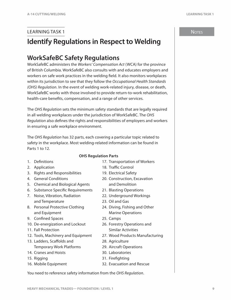
WorkSafeBC Safety RegulationsWorkSafeBC administers the Workers’ Compensation Act (WCA) for the province of British Columbia. WorkSafeBC also consults with and educates employers and workers on safe work practices in the welding �eld. It also monitors workplaces within its jurisdiction to see that they follow the Occupational Health Standards (OHS) Regulation. In the event of welding work-related injury, disease, or death, WorkSafeBC works with those involved to provide return-to-work rehabilitation, health-care bene�ts, compensation, and a range of other services.
The OHS Regulation sets the minimum safety standards that are legally required in all welding workplaces under the jurisdiction of WorkSafeBC. The OHS Regulation also de�nes the rights and responsibilities of employers and workers in ensuring a safe workplace environment.
The OHS Regulation has 32 parts, each covering a particular topic related to safety in the workplace. Most welding-related information can be found in Parts 1 to 12.
OHS Regulation Parts1. De�nitions 17. Transportation of Workers2. Application 18. Tra�c Control3. Rights and Responsibilities 19. Electrical Safety4. General Conditions 20. Construction, Excavation 5. Chemical and Biological Agents and Demolition6. Substance Speci�c Requirements 21. Blasting Operations7. Noise, Vibration, Radiation 22. Underground Workings
and Temperature 23. Oil and Gas8. Personal Protective Clothing 24. Diving, Fishing and Other
and Equipment Marine Operations9. Con�ned Spaces 25. Camps10. De-energization and Lockout 26. Forestry Operations and 11. Fall Protection Similar Activities12. Tools, Machinery and Equipment 27. Wood Products Manufacturing13. Ladders, Sca�olds and 28. Agriculture
Temporary Work Platforms 29. Aircraft Operations14. Cranes and Hoists 30. Laboratories15. Rigging 31. Fire�ghting16. Mobile Equipment 32. Evacuation and Rescue
You need to reference safety information from the OHS Regulation.

10 HEAVY MECHANICAL TRADES— FOUNDATION / LEVEL 1
SELF TEST 1 A-14 CUTTING/WELDING
SELF TEST 1
1. Why does WorkSafeBC enforce the Occupational Health and Safety Regulation?
a. to de�ne the rights and responsibilities of employers
b. to identify the safety standards that are legally required
c. to make amendments to the Workers’ Compensation Act
d. to protect every person in the workplace from work-related risks
2. What safety standard does the OHS Regulation provide?
a. maximum legal standard
b. minimum legal standard
c. �exible standard, not legally binding
d. general standard, not legally binding
HEAVY MECHANICAL TRADES— FOUNDATION / LEVEL 1 11
NOTES
A-14 CUTTING/WELDING LEARNING TASK 2
LEARNING TASK 2
Identify Metals
TerminologyThe following terms are used to describe metals and their properties:
Oxidize To oxidize is to combine an element with oxygen or convert an element into an oxide. For example, when carbon burns, it combines with oxygen to form either carbon dioxide or carbon monoxide. Iron combines with the oxygen in the air to form an iron oxide commonly known as rust.
Tensile Strength Tensile strength is the strength di�erent materials display when placed under tension. In the imperial system, tensile strength is measured in pounds per square inch (psi). In the metric system, tensile strength is measured in kilopascals (kPa) or Newtons per square millimeter (N/mm2). The area referred to (in2 or mm2) is the cross-sectional area of the material.
Ductility Ductility is the ability of metal to be bent, molded, or formed without breaking.
Malleable A malleable substance is one capable of being shaped or formed by hammering or by rolling. A malleable material may be bent without breaking.
Elasticity, Yield Point, Ultimate Tensile StrengthElasticity is the ability of a material to return to its original dimension after it has been strained or stretched. The yield point is where the elastic limit is reached and the material will not return to its original shape.
NOTES
12 HEAVY MECHANICAL TRADES— FOUNDATION / LEVEL 1
LEARNING TASK 2 A-14 CUTTING/WELDING
Fatigue Strength Fatigue strength is the ability of a metal to resist rapidly alternating stretching, twisting, and compressive stresses when the load is applied �rst from one direction and then from another.
For example, a welded trailer axle or frame undergoes a complete reversal of stresses, from tensile to compressive. Metals will fail under a changing load at lower stresses than they will if the load is steady. Care must be used when welding metals that will be subjected to alternating stresses.
Hardness Hardness is the ability of a metal to resist indentation or penetration. Hardness is usually linked to other properties of the metal such as its tensile strength. Tests used to determine hardness can also be used as an indicator of tensile strength. The harder of two metals of similar composition will have higher tensile strength, lower ductility, and more resistance to abrasive wear. High hardness also indicates low impact strength. When properly treated, some steels have both high hardness and good impact strength.
Alloy An alloy is a metal composed of two or more chemical elements, of which at least one is a metal.
Ferrous The term ferrous is applied to metals or alloys that contain 5% or more of iron.
Pig Iron Pig iron is the basic metal obtained from iron ore. Most ferrous metals begin as pig iron. It has a very high carbon content (2.5–4.5%) and is cast into bars called pigs.
Cast Iron Cast iron is re-smelted pig iron and includes all of the iron and carbon alloys with more than 2% carbon and almost always some silicon. High carbon and silicon contents give cast iron a low melting temperature and high �uidity in its liquid stage. It is easy to pour cast iron into complex moulds. Cast iron is used for engine blocks, heads, and housing assemblies.
Iron Soft malleable metals can be made by alloying pig iron and nickel. The resulting metal is known as nodular iron.

HEAVY MECHANICAL TRADES— FOUNDATION / LEVEL 1 13
NOTES
A-14 CUTTING/WELDING LEARNING TASK 2
Standard Steel Standard steel is an iron alloy containing manganese, carbon, or other alloying elements. Standard steel is stronger and harder than iron, yet it is softer than tool steel. The carbon content a�ects the properties of steel. About 0.2% carbon makes a structural steel such as would be used for a frame. Higher carbon content makes the steel harder. At 0.8% carbon, the steel is suitable for making drills and hammers.
Tool Steel Steel with a high content of carbon is called tool steel. It is hard enough to cut standard steel and iron. The metal must be able to withstand high temperatures, high load, and abrasive conditions. Because of the many applications of tools, tool steels vary in their composition.
Alloy Steel Steel is an alloy of iron and carbon. Nickel, chromium, molybdenum, tungsten, and vanadium may be added.
Stainless Steel Stainless steel contains chromium and usually nickel, in amounts up to a total of 25%. Stainless steel has high tensile strength, ductility, and hardness, as well as being highly resistant to corrosion and oxidation.
Non-ferrous Non-ferrous metals contain less than 5% iron and in most cases, no iron at all. Examples of non-ferrous metals are aluminum, copper, zinc, and lead. Included in this group of non-ferrous metals are alloys such as bronze and brass.
Aluminum Aluminum is light-weight and resistant to corrosion. It has low electrical resistance, high heat conductivity, good ductility, and considerable strength. Used extensively in the aeronautical industry, aluminum is also used for industrial tanks, truck and bus frames, and equipment body parts.
Copper Copper is fairly resistant to corrosion, has good tensile strength, and is an excellent conductor of electricity. Copper is highly resistant to many chemicals and to corrosion from air and seawater. It should not be used in contact with oxidizing acids.
Copper is malleable. As it is drawn or cold worked, it will increase in tensile strength and become less ductile. Copper is used for water supply lines, electrical wiring, and soft tubing.

NOTES
14 HEAVY MECHANICAL TRADES— FOUNDATION / LEVEL 1
LEARNING TASK 2 A-14 CUTTING/WELDING
Brass Brass is an alloy of copper and zinc. Brass is stronger than copper and is corrosive resistant, making it an ideal metal for ships’ �ttings, locks, and condenser tubes. Standard brass, which contains 30–34% zinc.
Lead Lead is a very dense, heavy metal. It has a low melting point of 327°C (620°F), making it easy to use in liquid form. Lead is also used in the construction of batteries and in solder.
Types of Steels and Their Classi�cationsThere are several ways steels can be grouped or classi�ed:
• chemical composition• mechanical properties• heat treatment• ease of machining• speci�c usage
Steels usually fall into one of three categories, based on their chemical composition:
• carbon steel• low-alloy steel• alloy steel
Carbon SteelPlain carbon steels have carbon as the only alloying element. These steels are classi�ed according to the percentage of carbon they contain and are called low-, medium-, and high-carbon steels. The chart in Figure 1 identi�es the carbon content of the categories of carbon steel and describes common applications.

HEAVY MECHANICAL TRADES— FOUNDATION / LEVEL 1 15
NOTES
A-14 CUTTING/WELDING LEARNING TASK 2
Carbon Content (%) Typical Uses
Low-carbon steel (0.10–0.30%) General-purpose steel for auto frames, wheels, welding electrodes, wire, sheet products, nails, tubing, structural steel
shapes, plate and bar, forgings
Medium-carbon steel (0.30–0.60%) Machine parts and tools, crankshafts, gears, axles
High-carbon steel (0.60–1.0%) Railroad rails, dies, springs, cold chisels, hammers, wrenches, band saws, axes
Very-high-carbon steel (1.0–1.7%) Twist drills, taps and dies, lathe tool �les, razors, ball races
Figure 1. Carbon Content for Di�erent Uses
Low-carbon SteelSteel in this category is tough, ductile, and easily machined and formed. All the commercial welding processes can successfully weld it. Low- carbon steel can be cast or shaped by forging. Most types do not respond to heat-treatment, but they can be quenched and tempered to enhance their mechanical properties.
Medium-carbon SteelHigher carbon content gives this steel high strength and hardness. It cannot be worked or welded as easily as low-carbon steel. Successful welding often requires special electrodes and care must be taken to prevent cracking in the weld area. Preheating and post-heating may also be necessary. The higher carbon content also means this steel can be successfully heat-treated.
High- and Very-high-carbon Steel (Tool Steel)This steel becomes very di�cult to weld as the carbon content increases. As a rule, steel up to 0.65% can be welded, provided special electrodes and heat treatments are used. With the high carbon content, this steel responds well to heat-treatment. It’s not usually practical or possible to successfully weld high-carbon steel beyond 0.65%.
NOTES
16 HEAVY MECHANICAL TRADES— FOUNDATION / LEVEL 1
LEARNING TASK 2 A-14 CUTTING/WELDING
Low-alloy Steel and Alloy SteelIn addition to carbon, these steels contain other elements that enhance speci�c properties of the steel. They can be added to improve strength and toughness, to increase or decrease hardenability, or to improve corrosion resistance. Although hardness is determined mainly by the carbon content, other properties such as ductility, machine-ability, or magnetic properties can be improved by adding other elements. Other than carbon, the main elements used in the low-alloy steel and alloy steel include:
• chromium• cobalt• copper• manganese• molybdenum• nickel• titanium• tungsten• vanadium
ChromiumChromium increases both the hardness and harden-ability of steel as well as its resistance to abrasion and corrosion. It also increases tensile strength. Chromium re�nes the grain structure of the steel, increasing its toughness. Chromium is used alone in carbon steel or in combination with other elements such as nickel, vanadium, molybdenum, or tungsten. Chromium is used in stainless steel and acid-resisting steels. Typical applications include tools, knives, instruments, and bearings.
CobaltCobalt improves the high-temperature properties or the magnetic properties of steel. The most common applications are magnetic products and high-speed, high- temperature cutting tools.
CopperCopper is used as an alloying element in steel to increase resistance to atmospheric corrosion. Copper-bearing steels are widely used for sheet roo�ng and siding.
ManganeseManganese is one of the most basic alloying elements in steel. It is an e�ective deoxidizer. It improves the grain structure and surface appearance of steel. It enhances the harden-ability, toughness, strength, and ductility.

HEAVY MECHANICAL TRADES— FOUNDATION / LEVEL 1 17
NOTES
A-14 CUTTING/WELDING LEARNING TASK 2
MolybdenumThis element produces the greatest hardening e�ect of any element except carbon and checks enlargement of the grain structure. Molybdenum also increases shock resistance, high-temperature strength, and corrosion resistance. Molybdenum-bearing steels �nd use in tools, machining parts, ball bearings, aircraft, and steam plants.
NickelNickel improves the ductility of steel without sacri�cing tensile strength. It also improves the low-temperature toughness of steel. Large quantities of nickel (25–35%) dramatically increase resistance to corrosion and shock. Nickel-bearing steel �nds wide use in tools, pressure vessels, armour, stainless steels, drills, gears, and ball bearings.
TitaniumTitanium is used to increase the high-temperature strength of steel. It can also be used to stabilize the grain structure of the steel or to act as a deoxidizer.
TungstenTungsten, when used as an alloying element in steel, improves the toughness, hardness, and wear resistance of the steel, notably at high temperatures. Tungsten in combination with cobalt gives steel red hardness. Tungsten (often combined with molybdenum and chromium) is used extensively in the high-speed, high-temperature steels from which tools are produced.
VanadiumVanadium is widely used in construction steel to produce a �ne grain structure and to promote toughness and shock resistance. Vanadium-bearing steel is used in high-strength pressure pipe, steel springs, gears, shafts, and axles where fatigue and impact resistance are prime considerations.
Structural ShapesMetals can be formed into di�erent shapes for use in a range of applications.
Sheet MetalSheet metal is formed in a long continuous roll or is cut into individual sheets of various dimensions. The sheets are formed in a rolling mill where the almost white-hot slabs of steel are passed through a succession of rollers. Each pair of rollers is set slightly closer to each other than the previous pair. The metal is squeezed thinner as it passes through each pair of rollers. Rolling continues until the metal is the desired thickness.
NOTES
18 HEAVY MECHANICAL TRADES— FOUNDATION / LEVEL 1
LEARNING TASK 2 A-14 CUTTING/WELDING
A gauge number designates the thickness of sheet metal. In this “gauge” system, the smaller the number, the thicker the sheet.
Sheet metal may be made from many metals, including steel, aluminum, copper, or brass. It may be rolled hot or cold, depending on the properties desired. For cold-rolling, the metal is rolled hot at �rst, then cooled before the �nal rolling process. Cold-rolling increases the strength and hardness of the steel, as well as producing a more accurate thickness than hot-rolling.
Sheet metal may be used for roof covering, heating and cooling ducts, door cladding, and work surfaces on work benches. Sheet metal is widely used in the manufacturing of simple items such as instrument panels, as well as more complex items such as automobile bodies and engine covers. When sheet steel requires protection from corrosion, it’s usually galvanized (coated with zinc).
PlateMetal is also available in a form known as plate. Plate is similar to sheet metal, but thicker. Sheets of metal are considered plate if they are at least 4.8 mm (3⁄16 in.) thick. Plate metal is available in �at sheets 150 mm (6 in.) or wider and in lengths up to 6 m (20 ft.).
Plate undergoes the same rolling process as sheet metal. Hot-rolled steel plate has a dark blue, scaly surface; while cold-rolled steel plate is smoother and has a sheen. Plate is used in heavy industry such as equipment manufacturing, truck decks, and general fabrication.
Round and Flat BarSteel is commonly used in solid round and �at bar shapes. Round bars in diameters of 20 mm (3⁄4 in.) and larger are available in lengths up to 6 m (20 ft.). Smaller diameter round bars may be coiled on spools for easier handling.
Flat bar is similar to plate except it is never wider than 150 mm (6 in.). Flat bar is available either hot-rolled or cold-rolled. Hot-rolled steel is scaly and dark blue or black. Cold-rolled steel is smoother, has a bright �nish, and is higher in tensile strength. Round and �at bar are used in a wide range of manufacturing and construction processes such as shafts and brackets.
AngleAngle shaped metal is available in many metals, including steel, aluminum, and wrought iron. The shape is used in manufacturing and fabricating and is more rigid than round or �at bar. Angle may be purchased in a variety of leg dimensions and in lengths up to 12 m (40 ft.).

HEAVY MECHANICAL TRADES— FOUNDATION / LEVEL 1 19
NOTES
A-14 CUTTING/WELDING LEARNING TASK 2
ChannelChannel is available in many standard dimensions and materials and in lengths up to 12 m (40 ft.). Channel is used extensively in construction and manufacturing.
TeeThe tee shape is a structural shape used mostly in large steel structures such as bridges or buildings. The shape provides rigidity in two directions while keeping weight to a minimum. Tees can be used for truck box dividers, mounts, and other applications.
TubingTubing is available in steel or aluminum in di�erent wall thickness. It is normally used for such items as rollover protection devices.
Other structural shapes include standard I-beam and wide �ange I-beam.
Storage and HandlingThe purpose in storing any product is to:
• provide easy access to materials• provide easy identi�cation of materials• protect the products from physical damage• protect personnel from injury by materials• facilitate inventory of stock• protect the �nish of the product• prevent theft• prevent loss

NOTES
20 HEAVY MECHANICAL TRADES— FOUNDATION / LEVEL 1
LEARNING TASK 2 A-14 CUTTING/WELDING
Structural metal shapes are extremely heavy and can cause serious injury. Always make sure that you wear the appropriate safety equipment including boots and head protection. Protect your hands by wearing gloves and always keep your hands out of areas where they could be pinched by shifting material. Never attempt to lift structural shapes by hand. Always use proper lifting devices and correct rigging practices:
• Place steel on organized racks.• Place similar shapes together.• Place the large pieces on the lower areas.• Make sure the racks and steel are protected from water (rust).• Use a forklift to lift and move the steel.• Wear gloves, steel-toe shoes, and safety glasses when handling steel.• Get help when handling long pieces.
Depending on the type and shape of metal, di�erent storage practices must be followed to achieve the above goals.
HEAVY MECHANICAL TRADES— FOUNDATION / LEVEL 1 21
A-14 CUTTING/WELDING SELF TEST 2
SELF TEST 2
1. What is tensile strength of a material?
a. ability to withstand forces pulling apart
b. ability to withstand forces crush it
c. ability to withstand forces bend it
d. ability to withstand forces wearing on it
2. What 5% material is added to Ferrous metals?
a. zinc
b. lead
c. iron
d. carbon

22 HEAVY MECHANICAL TRADES— FOUNDATION / LEVEL 1

HEAVY MECHANICAL TRADES— FOUNDATION / LEVEL 1 23
NOTES
A-14 CUTTING/WELDING LEARNING TASK 3
LEARNING TASK 3
Identify Oxy-acetylene Components
GasesOxy-fuel gas-cutting involves the mixing of two gases to complete the cutting process. One of these gases is always oxygen. The other gas is the fuel gas. The fuel gas can be acetylene, natural gas, propane, methylacetylene-propadiene (Mapp®), or propylene. It is useful to know something of the properties and application of these gases.
Oxygen (O2)Oxygen is a colourless, odourless, and tasteless gas found in our atmosphere. It supports both life and combustion.
Our atmosphere consists of about 21% oxygen, 78% nitrogen, and 1% other gases. The large nitrogen content in our air tends to slow down combustion or burning. Materials that burn in our normal atmosphere will burn much faster and more vigorously in pure oxygen. Other substances that do not burn in air (such as iron) burn very well in pure oxygen. It’s this property that makes oxygen e�ective in cutting iron and steel. It is also this property that makes oxygen extremely dangerous.
Many substances that are not considered �ammable will burn with explosive violence in pure oxygen. Oxygen will cause oil and grease to explode into �ame.
Keep oil and grease away from oxygen equipment. Never use oil on oxygen cylinder pressure regulators, cylinder valves, or torch valves.

NOTES
24 HEAVY MECHANICAL TRADES— FOUNDATION / LEVEL 1
LEARNING TASK 3 A-14 CUTTING/WELDING
Acetylene (C2H2)Acetylene is a compound formed by uniting two carbon atoms and two hydrogen atoms. It is colourless, but it has a strong, pungent odour. The average person can smell as little as 1% acetylene in the air. This odour makes acetylene leaks easy to detect.
Acetylene is used in oxy-fuel gas-cutting because it burns at an extremely high temperature. When acetylene is mixed with oxygen, the resulting �ame can reach 3480°C (6300°F). This is the highest �ame temperature produced from the combustion of oxygen and any fuel gas. This high �ame temperature makes acetylene the most preferred of the fuel gases.
Acetylene is �ammable and highly explosive. Even a small proportion of acetylene in the air can explode. It is important to treat any mixture of air or oxygen and acetylene as potentially explosive. Immediately extinguish all open �ames and ventilate the room before even turning on a light switch. Test the acetylene equipment for leaks and repair them immediately.
Acetylene is also a very unstable compound. The term “unstable” means that the material is likely to break down (decompose) or undergo a physical change because of slight variations in temperature or pressure. The point at which a material breaks down is called its “critical point.”
The critical point of acetylene is 193 kPa (28 psi) pressure at 21°C (70°F). At this point, acetylene breaks down into carbon and hydrogen and explodes. If the temperature is higher, the pressure at which acetylene breaks down will be lower. To allow for temperature �uctuations in a work area, the maximum working pressure for free acetylene is set at 103 kPa (15 psi).
Cylinders used for acetylene are packed with a porous �ller such as asbestos, charcoal, or balsa wood. The cylinder is then �lled with liquid acetone in which acetylene is dissolved. The �ller absorbs the liquid acetone. Free acetylene is con�ned to small pockets of gas. In this way, there is a minimal amount of free acetylene in the cylinder. This means the pressure in the cylinders can be high, about 1.7 MPa (250 psi).
Acetylene gas reacts with copper to form acetylide, a residue that is even more unstable than acetylene. The slightest jolt can cause an explosion. Fire will most certainly result. There could be injury or loss of life. Never use copper or red brass �ttings or tubing on acetylene systems. Use only �ttings of yellow brass, iron, or steel.

HEAVY MECHANICAL TRADES— FOUNDATION / LEVEL 1 25
NOTES
A-14 CUTTING/WELDING LEARNING TASK 3
Other GasesFor several reasons, fuel gases other than acetylene are often used in oxy-fuel gas-cutting. It is extremely important to remember that all of these gases are potentially explosive and you must use extreme care when working with them. The more common fuel gases are:
• natural gas• propane• methylacetylene-propadiene (MPS or Mapp®)• propylene
These fuel gases each need a di�erent amount of oxygen in order to produce a neutral �ame (a �ame that burns the fuel gas completely) (Figure 1). The question of how much oxygen you need to completely burn the fuel gas is important in terms of cost, the convenience of working with the equipment, and the availability of oxygen.
Specially designed cutting tips and, in some cases, mixing chambers are necessary with the liquid fuels, MPS gas, and propane, as the amount of oxygen required to burn them completely is considerably higher than with acetylene.
Fuel Gas Oxygen to Fuel GasAcetylene 1 to 1
Propane 4.5 to 1
Natural gas 2 to 1
MPS 2.5 to 1
Propylene 2.6 to 1
Figure 1. Volumes of Oxygen to Fuel Gas Required for a Neutral Flame
For some cutting operations, these fuel gases might be preferred over acetylene for reasons other than cost. Acetylene and oxygen generate the highest �ame temperature, which permits fast starts when cutting. Although the other fuel gases have lower �ame temperatures and slower starts, they produce cleaner cuts than acetylene, with little or no slag clinging to the bottom of the cut.
Acetylene has a limited draw-o� rate, so it cannot be used with large tips unless you also use a manifold system. Other fuel gases have higher draw-o� rates, which means you can use large tips. This is especially critical when you are using large heating tips or cutting sections that are more than 125 mm (5 in.) thick.

NOTES
26 HEAVY MECHANICAL TRADES— FOUNDATION / LEVEL 1
LEARNING TASK 3 A-14 CUTTING/WELDING
Natural Gas (CH4)Natural gas is often preferred in areas where it can be piped in because it eliminates the dangerous and time-consuming handling of fuel cylinders. Natural gas generates a �ame temperature of 2540°C (4600°F), which is lower than that of acetylene or Mapp® gas. Although it takes longer to preheat the metal and cutting speeds are slower, natural gas is a common alternative to acetylene because it is inexpensive and convenient. It is delivered at such low pressure that special injector-type torches are needed.
Propane Gas (C3H8)Propane gas is supplied in liquid form in low-pressure cylinders. It is widely used because it produces clean cuts and is relatively inexpensive. Propane has a high heat value but requires 4½ volumes of oxygen to 1 volume of propane to burn completely. The �ame temperature is similar to natural gas, 2540°C (4600°F). Propane is stored in liquid form for convenient and safe handling.
Methylacetylene-Propadiene Gas (C6H8)Rearranging the molecules in acetylene and propane to form a new compound, methylacetylene-propadiene (MPS), a stabilized gas is produced. It is sold in di�erent con�gurations under such trade names as Mapp® gas and FG (Fuel Gas). This compound is much more stable and less explosive than acetylene, and it produces a �ame almost as hot, 2900°C (5300°F). Like acetylene, it has a strong odour, so leaks are easy to detect.
MPS gas is stored in a lique�ed form under high pressure. One cylinder contains the same volume as �ve acetylene cylinders. The capability of using higher working pressures makes MPS gas e�ective for underwater cutting where acetylene would be ine�ective. Because MPS gas is so stable, the cylinders are safe and easy to handle.
The slightly lower �ame temperature makes for slower cuts, but with its clear advantage in safety, MPS gas is an attractive alternative to acetylene.
Propylene (C3H6)Propylene fuel gas is a byproduct of the crude oil re�ning process. It’s sold under trade names such as Apache®, B-Plus ®, H.P.G.®, T9®, UCON 96®, and Victorgas®. It’s available in its pure form or it might have other fuel gases added to it. One volume of propylene requires a minimum of 2.6 volumes of oxygen for a neutral �ame. The combustion characteristics of the propylene �ame are similar to those of methylacetylene-propadiene and therefore propylene uses much of the same equipment.

HEAVY MECHANICAL TRADES— FOUNDATION / LEVEL 1 27
NOTES
A-14 CUTTING/WELDING LEARNING TASK 3
CylindersMost welders use oxygen and fuel gas from cylinders. Since these cylinders are an important part of your gas-cutting equipment, it’s important that you know about their construction and safety precautions when using them.
Cylinders are not generally sold. Suppliers, who regularly pick up the empty cylinders and replace them with full ones, usually rent them. The supplier is also responsible for maintaining the cylinder in safe working condition. Any defects should be reported to the supplier immediately.
Oxygen CylindersOxygen is available either as a gas in high-pressure cylinders or as a liquid in relatively low-pressure “cryogenic” cylinders.
High-pressure Oxygen CylindersHigh-pressure oxygen cylinders are forged from a single piece of strong, high-carbon steel, with walls at least 6 mm (1⁄4 in.) thick. High-pressure oxygen cylinders have a threaded collar, compression-�tted to the top of the cylinder, for the removable protective cap to screw on to. They’re available in a variety of capacities, ranging from 0.5–9.35 m3 (20–335 ft.3) (Figure 2).
Oxygen cylinders are made in various sizes ranging from 0.5–7 m3
(20–244 ft.3) capacity. The oxygen is compressed to 2200 psi (15 MPa) at 21°C (70°F).
1422 mm (56")
Wallthickness6 mm (¼")
Safety devicein valveRemovable
protective cap
230 mm (9")
Figure 2. Typical 7 m3 Oxygen Cylinder
NOTES
28 HEAVY MECHANICAL TRADES— FOUNDATION / LEVEL 1
LEARNING TASK 3 A-14 CUTTING/WELDING
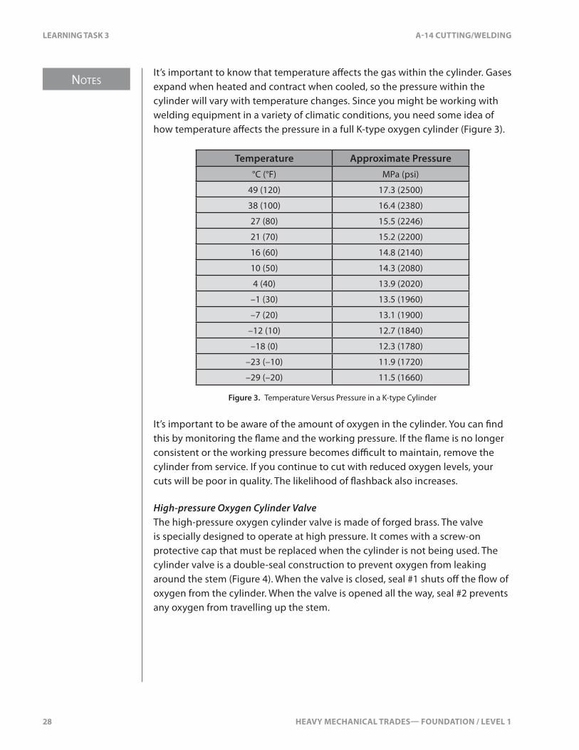
It’s important to know that temperature a�ects the gas within the cylinder. Gases expand when heated and contract when cooled, so the pressure within the cylinder will vary with temperature changes. Since you might be working with welding equipment in a variety of climatic conditions, you need some idea of how temperature a�ects the pressure in a full K-type oxygen cylinder (Figure 3).
Temperature Approximate Pressure°C (°F) MPa (psi)
49 (120) 17.3 (2500)
38 (100) 16.4 (2380)
27 (80) 15.5 (2246)
21 (70) 15.2 (2200)
16 (60) 14.8 (2140)
10 (50) 14.3 (2080)
4 (40) 13.9 (2020)
–1 (30) 13.5 (1960)
–7 (20) 13.1 (1900)
–12 (10) 12.7 (1840)
–18 (0) 12.3 (1780)
–23 (–10) 11.9 (1720)
–29 (–20) 11.5 (1660)
Figure 3. Temperature Versus Pressure in a K-type Cylinder
It’s important to be aware of the amount of oxygen in the cylinder. You can �nd this by monitoring the �ame and the working pressure. If the �ame is no longer consistent or the working pressure becomes di�cult to maintain, remove the cylinder from service. If you continue to cut with reduced oxygen levels, your cuts will be poor in quality. The likelihood of �ashback also increases.
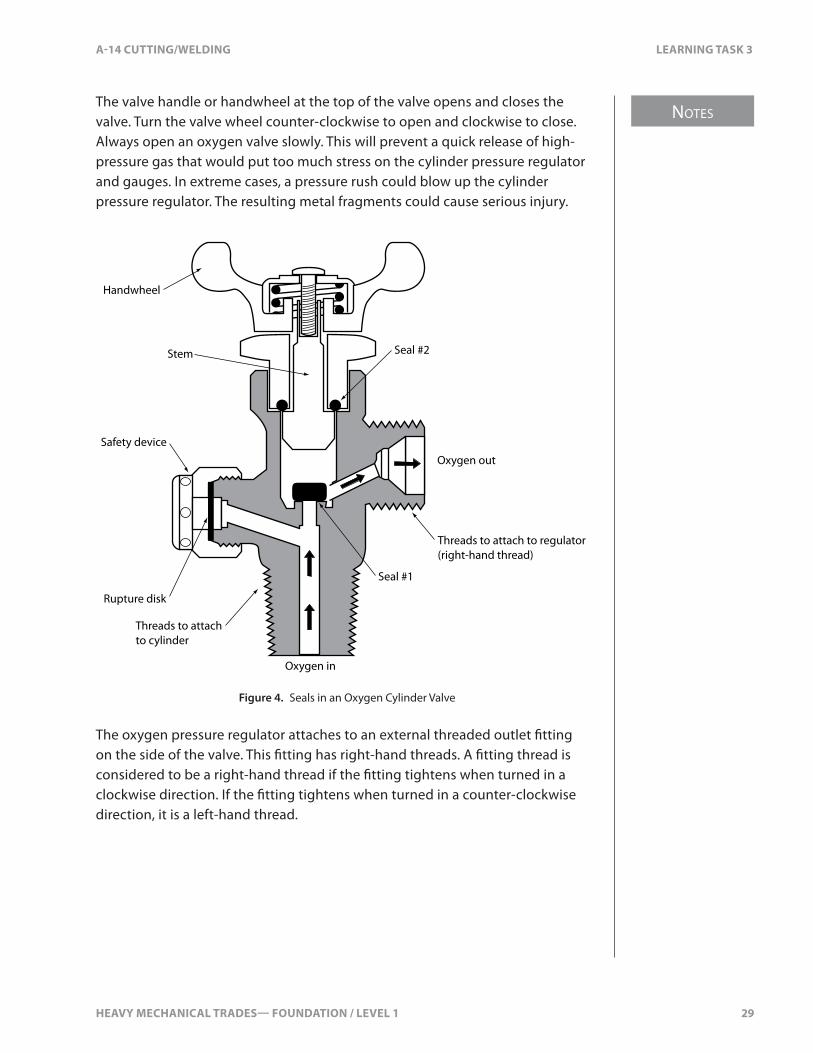
High-pressure Oxygen Cylinder ValveThe high-pressure oxygen cylinder valve is made of forged brass. The valve is specially designed to operate at high pressure. It comes with a screw-on protective cap that must be replaced when the cylinder is not being used. The cylinder valve is a double-seal construction to prevent oxygen from leaking around the stem (Figure 4). When the valve is closed, seal #1 shuts o� the �ow of oxygen from the cylinder. When the valve is opened all the way, seal #2 prevents any oxygen from travelling up the stem.
HEAVY MECHANICAL TRADES— FOUNDATION / LEVEL 1 29
NOTES
A-14 CUTTING/WELDING LEARNING TASK 3
The valve handle or handwheel at the top of the valve opens and closes the valve. Turn the valve wheel counter-clockwise to open and clockwise to close. Always open an oxygen valve slowly. This will prevent a quick release of high-pressure gas that would put too much stress on the cylinder pressure regulator and gauges. In extreme cases, a pressure rush could blow up the cylinder pressure regulator. The resulting metal fragments could cause serious injury.
Handwheel
Stem
Rupture disk
Safety device
Oxygen out
Seal #1
Seal #2
Oxygen in
Threads to attach to regulator(right-hand thread)
Threads to attachto cylinder
Figure 4. Seals in an Oxygen Cylinder Valve
The oxygen pressure regulator attaches to an external threaded outlet �tting on the side of the valve. This �tting has right-hand threads. A �tting thread is considered to be a right-hand thread if the �tting tightens when turned in a clockwise direction. If the �tting tightens when turned in a counter-clockwise direction, it is a left-hand thread.

NOTES
30 HEAVY MECHANICAL TRADES— FOUNDATION / LEVEL 1
LEARNING TASK 3 A-14 CUTTING/WELDING
High-pressure Oxygen Cylinder Valve Safety DeviceHigh-pressure oxygen cylinder valves also have a safety device. Outside the valve is a capped hexagonal nut that has small holes around the perimeter of the cap. Inside is a safety disk, made of a special material that will burst if the pressure inside the cylinder gets too high (Figure 5). If the cylinder temperature rises, the pressure increases, causing the safety disk to rupture and release the oxygen through the small holes in the hexagonal nut. Opposing vent holes allow the pressurized gas to be evenly di�used and prevent the blast e�ect of a single vent. The pressure at which the disk ruptures is 27 MPa (4000 psi).
Ruptured disk
Vent holes
Oxygen from cylinder
Figure 5. Oxygen Cylinder Safety Device
Never try to repair a damaged cylinder valve or ruptured safety disk. Tag the cylinder to indicate the fault, move it to an open area, and notify the supplier to pick it up immediately.
Liquid Oxygen CylindersWhen you need large volumes of oxygen, it is more economical to have liquid oxygen supplied in cryogenic containers. The term “cryogenic” means “low temperatures,” usually at or below –130°C (–200°F). Cryogenic containers are very much like large thermos bottles in that they have an inner and outer container arrangement.
The boiling point of oxygen is –183°C (–297°F). This means that oxygen converts to a liquid when cooled below a temperature of –183°C (–297°F). Storing gases in their liquid state allows the container to hold much higher volumes of gas. Oxygen, for example, has a cryogenic liquid-to-gas expansion ratio of 1 to 861.

HEAVY MECHANICAL TRADES— FOUNDATION / LEVEL 1 31
NOTES
A-14 CUTTING/WELDING LEARNING TASK 3
Acetylene Gas CylindersAcetylene gas cylinders are strong, welded-steel containers that are specially designed to store the highly unstable and explosive acetylene gas. The cylinder is completely �lled with a porous material such as monolithic �ller, asbestos, charcoal, or balsa wood. This �ller material is then saturated with acetone, which has the ability to absorb twenty times its volume in acetylene gas. The inside of the cylinder resembles a very �ne honeycomb. The honeycomb arrangement localizes the gas in small pockets, reducing the possibility of explosion. The acetone stabilizes the acetylene so that it can be contained at a higher pressure. The �ne honeycomb prevents the mixture of acetylene and acetone from sloshing around, which would cause it to separate and possibly explode.
With this arrangement, acetylene cylinders can be charged (�lled) beyond the normal critical zone of 103 kPa (15 psi). The cylinders can be charged to much higher pressures, around 1.7 MPa (250 psi), so they can hold much more acetylene.
Acetylene cylinders must be kept upright when in use. If not, the liquid acetone could �ow into the system. Acetone would damage the acetylene pressure regulator, hoses, and �ttings. If it reaches the torch, acetone will contaminate the �ame, resulting in poor-quality cuts.
Acetylene cylinders are normally shorter and larger in diameter than oxygen cylinders. They are available in a variety of capacities from 0.28–10.8 m3 (10–380 ft.3).
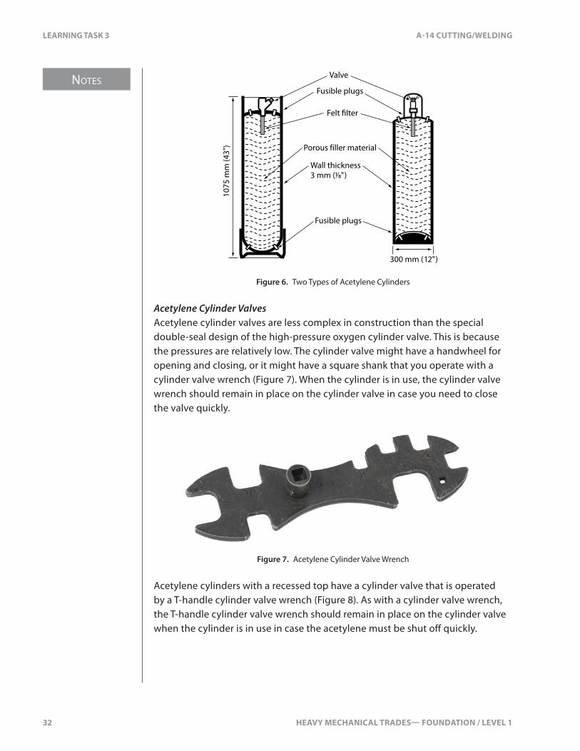
Acetylene cylinders come in two basic types. The more common type has a rounded top with a protective cap that �ts over and protects the cylinder valve. The other type has a recessed top that by design protects the cylinder valve (Figure 6).
NOTES
32 HEAVY MECHANICAL TRADES— FOUNDATION / LEVEL 1
LEARNING TASK 3 A-14 CUTTING/WELDING
Valve
Fusible plugs
Fusible plugs
Porous filler material
1075
mm
(43"
)
300 mm (12")
Wall thickness3 mm (1⁄8")
Felt �lter
Figure 6. Two Types of Acetylene Cylinders
Acetylene Cylinder ValvesAcetylene cylinder valves are less complex in construction than the special double-seal design of the high-pressure oxygen cylinder valve. This is because the pressures are relatively low. The cylinder valve might have a handwheel for opening and closing, or it might have a square shank that you operate with a cylinder valve wrench (Figure 7). When the cylinder is in use, the cylinder valve wrench should remain in place on the cylinder valve in case you need to close the valve quickly.
Figure 7. Acetylene Cylinder Valve Wrench
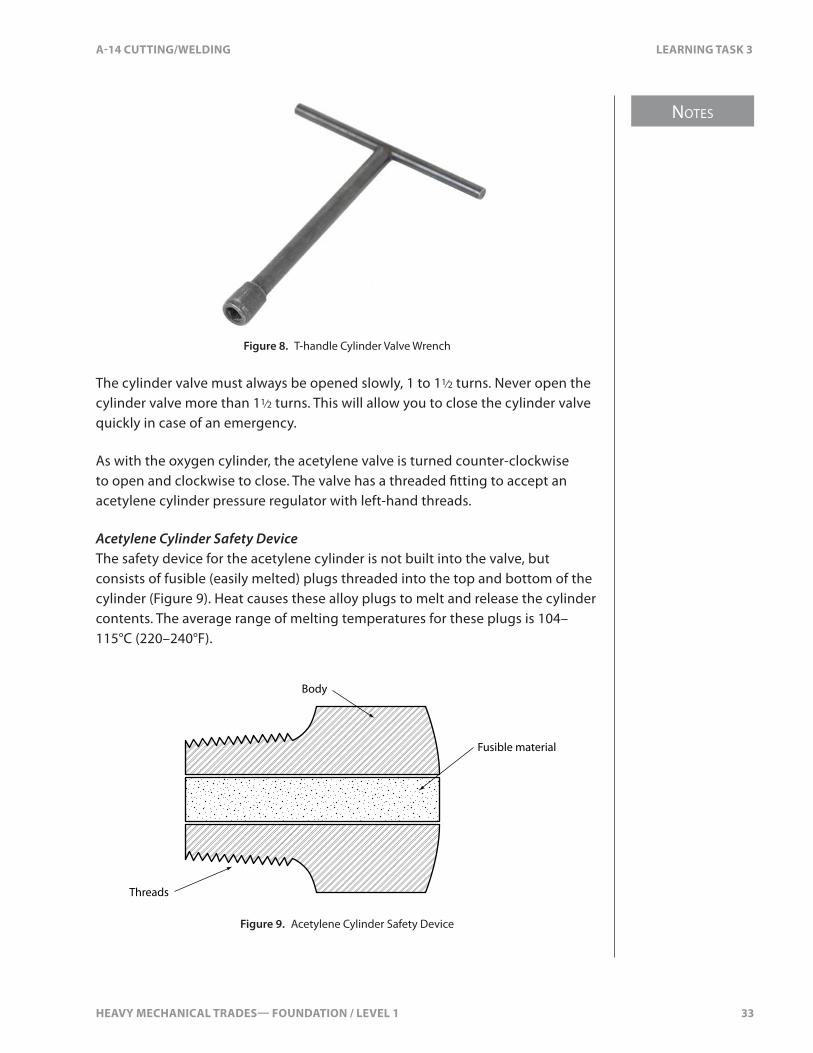
Acetylene cylinders with a recessed top have a cylinder valve that is operated by a T-handle cylinder valve wrench (Figure 8). As with a cylinder valve wrench, the T-handle cylinder valve wrench should remain in place on the cylinder valve when the cylinder is in use in case the acetylene must be shut o� quickly.
HEAVY MECHANICAL TRADES— FOUNDATION / LEVEL 1 33
NOTES
A-14 CUTTING/WELDING LEARNING TASK 3
Figure 8. T-handle Cylinder Valve Wrench
The cylinder valve must always be opened slowly, 1 to 11⁄2 turns. Never open the cylinder valve more than 11⁄2 turns. This will allow you to close the cylinder valve quickly in case of an emergency.
As with the oxygen cylinder, the acetylene valve is turned counter-clockwise to open and clockwise to close. The valve has a threaded �tting to accept an acetylene cylinder pressure regulator with left-hand threads.
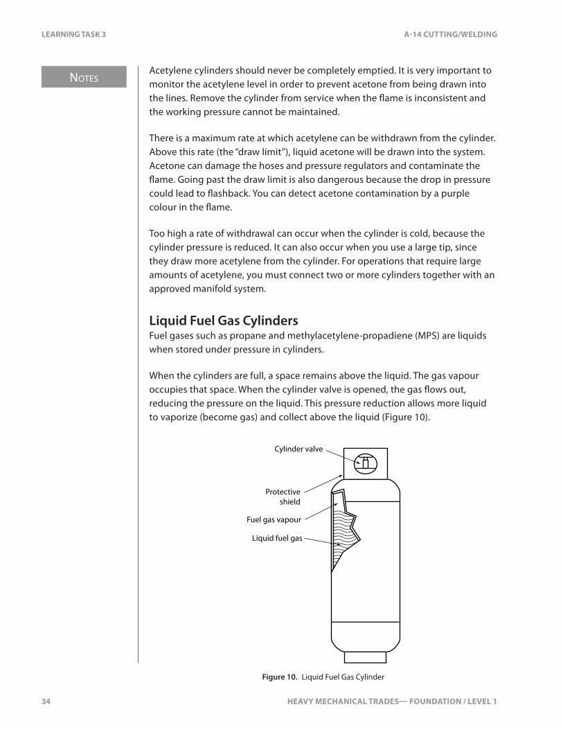
Acetylene Cylinder Safety DeviceThe safety device for the acetylene cylinder is not built into the valve, but consists of fusible (easily melted) plugs threaded into the top and bottom of the cylinder (Figure 9). Heat causes these alloy plugs to melt and release the cylinder contents. The average range of melting temperatures for these plugs is 104–115°C (220–240°F).
Threads
Body
Fusible material
Figure 9. Acetylene Cylinder Safety Device
NOTES
34 HEAVY MECHANICAL TRADES— FOUNDATION / LEVEL 1
LEARNING TASK 3 A-14 CUTTING/WELDING
Acetylene cylinders should never be completely emptied. It is very important to monitor the acetylene level in order to prevent acetone from being drawn into the lines. Remove the cylinder from service when the �ame is inconsistent and the working pressure cannot be maintained.
There is a maximum rate at which acetylene can be withdrawn from the cylinder. Above this rate (the “draw limit”), liquid acetone will be drawn into the system. Acetone can damage the hoses and pressure regulators and contaminate the �ame. Going past the draw limit is also dangerous because the drop in pressure could lead to �ashback. You can detect acetone contamination by a purple colour in the �ame.
Too high a rate of withdrawal can occur when the cylinder is cold, because the cylinder pressure is reduced. It can also occur when you use a large tip, since they draw more acetylene from the cylinder. For operations that require large amounts of acetylene, you must connect two or more cylinders together with an approved manifold system.
Liquid Fuel Gas CylindersFuel gases such as propane and methylacetylene-propadiene (MPS) are liquids when stored under pressure in cylinders.
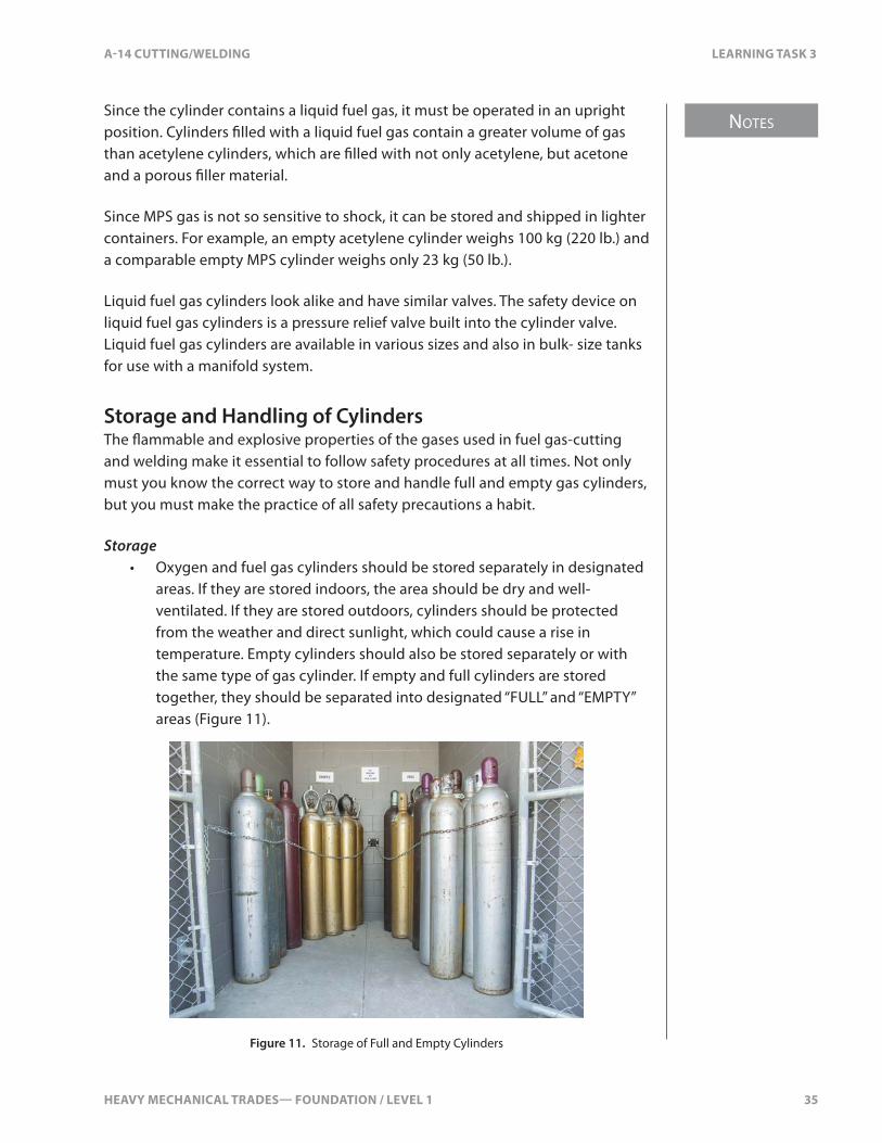
When the cylinders are full, a space remains above the liquid. The gas vapour occupies that space. When the cylinder valve is opened, the gas �ows out, reducing the pressure on the liquid. This pressure reduction allows more liquid to vaporize (become gas) and collect above the liquid (Figure 10).
Cylinder valve
Protectiveshield
Fuel gas vapour
Liquid fuel gas
Figure 10. Liquid Fuel Gas Cylinder
HEAVY MECHANICAL TRADES— FOUNDATION / LEVEL 1 35
NOTES
A-14 CUTTING/WELDING LEARNING TASK 3
Since the cylinder contains a liquid fuel gas, it must be operated in an upright position. Cylinders �lled with a liquid fuel gas contain a greater volume of gas than acetylene cylinders, which are �lled with not only acetylene, but acetone and a porous �ller material.
Since MPS gas is not so sensitive to shock, it can be stored and shipped in lighter containers. For example, an empty acetylene cylinder weighs 100 kg (220 lb.) and a comparable empty MPS cylinder weighs only 23 kg (50 lb.).
Liquid fuel gas cylinders look alike and have similar valves. The safety device on liquid fuel gas cylinders is a pressure relief valve built into the cylinder valve. Liquid fuel gas cylinders are available in various sizes and also in bulk- size tanks for use with a manifold system.
Storage and Handling of CylindersThe �ammable and explosive properties of the gases used in fuel gas-cutting and welding make it essential to follow safety procedures at all times. Not only must you know the correct way to store and handle full and empty gas cylinders, but you must make the practice of all safety precautions a habit.
Storage• Oxygen and fuel gas cylinders should be stored separately in designated
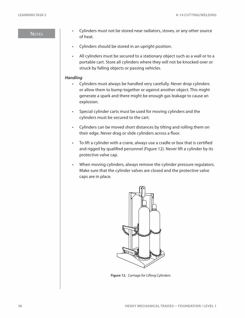
areas. If they are stored indoors, the area should be dry and well-ventilated. If they are stored outdoors, cylinders should be protected from the weather and direct sunlight, which could cause a rise in temperature. Empty cylinders should also be stored separately or with the same type of gas cylinder. If empty and full cylinders are stored together, they should be separated into designated “FULL” and “EMPTY” areas (Figure 11).
Figure 11. Storage of Full and Empty Cylinders
NOTES
36 HEAVY MECHANICAL TRADES— FOUNDATION / LEVEL 1
LEARNING TASK 3 A-14 CUTTING/WELDING
• Cylinders must not be stored near radiators, stoves, or any other source of heat.
• Cylinders should be stored in an upright position.
• All cylinders must be secured to a stationary object such as a wall or to a portable cart. Store all cylinders where they will not be knocked over or struck by falling objects or passing vehicles.
Handling• Cylinders must always be handled very carefully. Never drop cylinders
or allow them to bump together or against another object. This might generate a spark and there might be enough gas leakage to cause an explosion.
• Special cylinder carts must be used for moving cylinders and the cylinders must be secured to the cart.
• Cylinders can be moved short distances by tilting and rolling them on their edge. Never drag or slide cylinders across a �oor.
• To lift a cylinder with a crane, always use a cradle or box that is certi�ed and rigged by quali�ed personnel (Figure 12). Never lift a cylinder by its protective valve cap.
• When moving cylinders, always remove the cylinder pressure regulators. Make sure that the cylinder valves are closed and the protective valve caps are in place.
Figure 12. Carriage for Lifting Cylinders
HEAVY MECHANICAL TRADES— FOUNDATION / LEVEL 1 37
NOTES
A-14 CUTTING/WELDING LEARNING TASK 3
Safety Precautions• Keep cylinders away from live electrical wiring.
• Keep oxygen and fuel gas cylinders as far as possible from any area where sparks or �ame from welding or cutting could contact them.
• Never cut or weld directly over cylinders.
• To prevent an explosion, keep oily and greasy substances away from the oxygen cylinders, valves, hoses, �ttings, and attachments. Take care to keep oil, paint, and grease cans far away from your oxy-fuel gas equipment. Wipe up oil spots immediately. Keep hoses and welding equipment o� the �oor. Never oil or grease cylinder valves, pressure regulators, torches, or other oxy-fuel gas equipment.
• Do not use leaky fuel gas cylinders. A leaking fuel gas cylinder must be moved to an area where good ventilation exists (preferably outdoors) and warning signs must be displayed to prohibit sources of ignition. Always operate oxygen cylinder valves by hand. Never strike a cylinder valve with a wrench or hammer, as this could cause a spark. If a cylinder valve is clogged with snow or ice, use warm water to thaw it. Never use a �ame.
• Never tamper with or try to repair cylinder valves. If a cylinder valve does not function properly, notify the supplier.
• Never tamper with cylinder safety devices.
• When not in use, cylinder valves must be closed and the protective valve caps installed.
Pressure Regulators and Their FunctionsOxygen and Fuel Pressure RegulatorsOxygen and fuel gases are stored in cylinders at pressures much greater than the pressures required to perform cutting or welding tasks. For example, the pressure of a full K-type oxygen cylinder is 15 MPa (2200 psi), while the actual working pressure required at the cutting torch might only be 275 kPa (40 psi). Pressure regulators are installed on cylinders to control the �ow of gas from the cylinder so that a lower working pressure can be maintained.
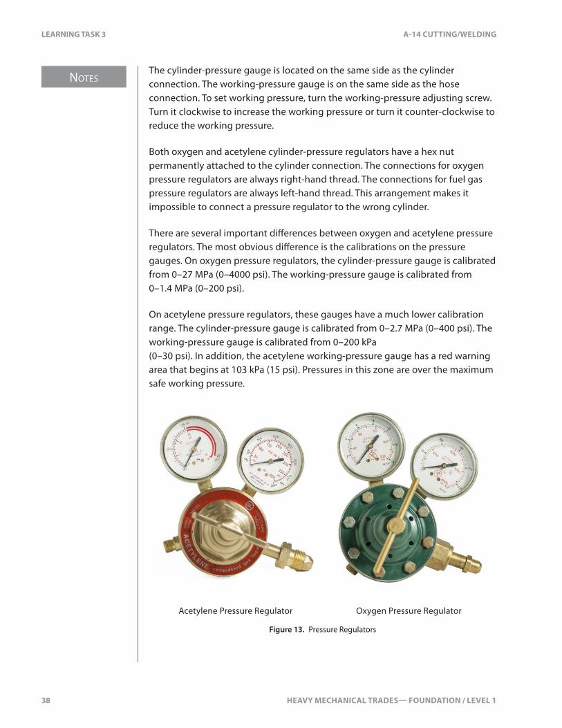
Oxygen and acetylene cylinder pressure regulators have many features in common (Figure 13). They are usually made from a solid piece of brass or aluminum. Most of them have two calibrated gauges attached. The gauge with the higher numbers (calibrations) shows the pressure in the cylinder. The gauge with the lower calibrations shows the working pressure.
NOTES
38 HEAVY MECHANICAL TRADES— FOUNDATION / LEVEL 1
LEARNING TASK 3 A-14 CUTTING/WELDING
The cylinder-pressure gauge is located on the same side as the cylinder connection. The working-pressure gauge is on the same side as the hose connection. To set working pressure, turn the working-pressure adjusting screw. Turn it clockwise to increase the working pressure or turn it counter-clockwise to reduce the working pressure.
Both oxygen and acetylene cylinder-pressure regulators have a hex nut permanently attached to the cylinder connection. The connections for oxygen pressure regulators are always right-hand thread. The connections for fuel gas pressure regulators are always left-hand thread. This arrangement makes it impossible to connect a pressure regulator to the wrong cylinder.
There are several important di�erences between oxygen and acetylene pressure regulators. The most obvious di�erence is the calibrations on the pressure gauges. On oxygen pressure regulators, the cylinder-pressure gauge is calibrated from 0–27 MPa (0–4000 psi). The working-pressure gauge is calibrated from 0–1.4 MPa (0–200 psi).
On acetylene pressure regulators, these gauges have a much lower calibration range. The cylinder-pressure gauge is calibrated from 0–2.7 MPa (0–400 psi). The working-pressure gauge is calibrated from 0–200 kPa (0–30 psi). In addition, the acetylene working-pressure gauge has a red warning area that begins at 103 kPa (15 psi). Pressures in this zone are over the maximum safe working pressure.
Acetylene Pressure Regulator Oxygen Pressure Regulator
Figure 13. Pressure Regulators
HEAVY MECHANICAL TRADES— FOUNDATION / LEVEL 1 39
NOTES
A-14 CUTTING/WELDING LEARNING TASK 3
Acetylene working pressure must be kept below 103 kPa (15 psi) to prevent the unstable acetylene gas from exploding.
Pressure regulators are usually identi�ed by the type of gas for which they are to be used. Oxygen pressure regulators have the word “oxygen” printed on the regulator body and one or both gauges. The word “acetylene” is printed on the body and one or both gauges of acetylene pressure regulators.
The gas hose and cylinder connections are threaded di�erently. Oxygen pressure regulators have an internal right-hand thread connection. Acetylene pressure regulators, depending on the supplier, have either an internal or an external left-hand thread connection. In addition, the hex nut on an acetylene pressure regulator is grooved while the hex nut on an oxygen pressure regulator is plain. There are variations in the �tting connections on acetylene cylinders, but the �tting connections on the acetylene pressure regulator can be changed by the use of adapters to suit the di�erent styles of cylinder valves.
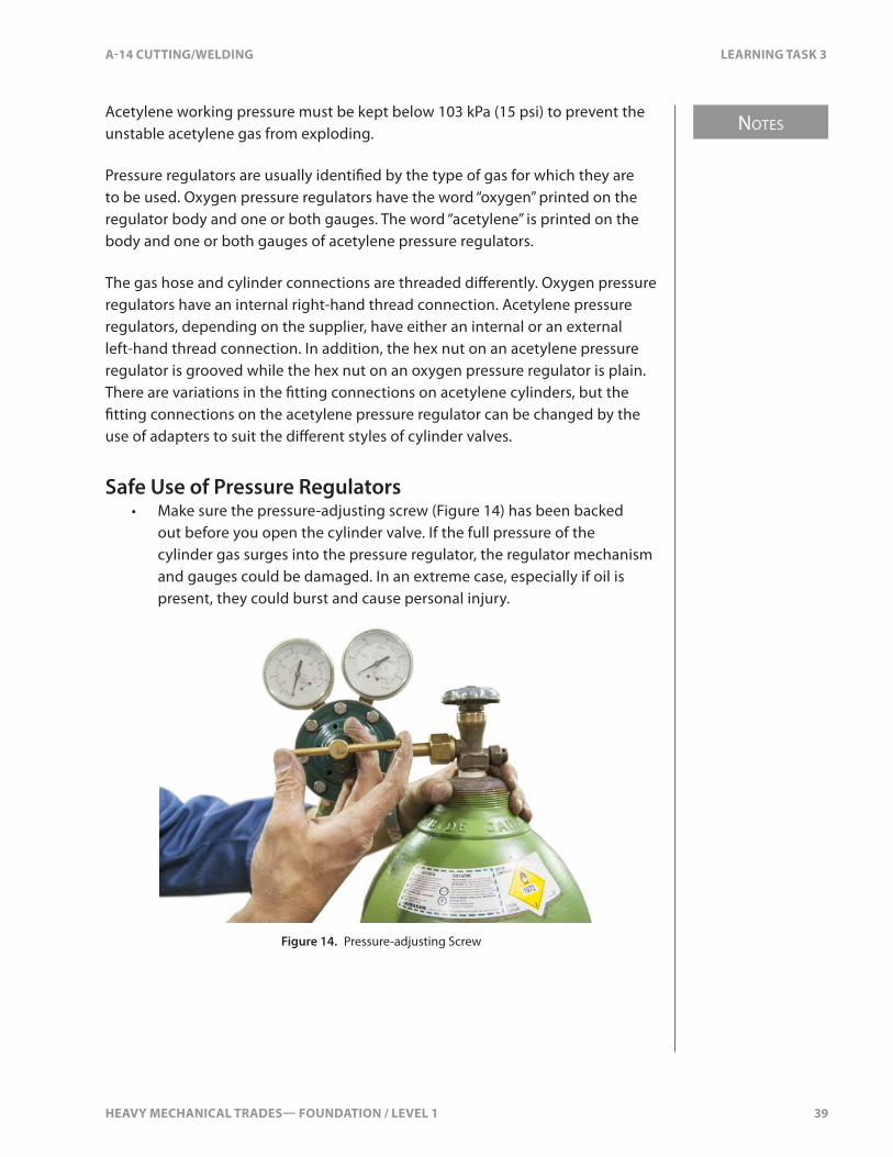
Safe Use of Pressure Regulators• Make sure the pressure-adjusting screw (Figure 14) has been backed
out before you open the cylinder valve. If the full pressure of the cylinder gas surges into the pressure regulator, the regulator mechanism and gauges could be damaged. In an extreme case, especially if oil is present, they could burst and cause personal injury.
Figure 14. Pressure-adjusting Screw
NOTES
40 HEAVY MECHANICAL TRADES— FOUNDATION / LEVEL 1
LEARNING TASK 3 A-14 CUTTING/WELDING
• Watch for a “creeping” pressure regulator. This occurs when the gas hoses and torch are attached, the working pressure is set, and the torch valves are closed. The working-pressure gauge tends to “creep up” or increase. A faulty valve seat in the pressure regulator usually causes this. It should be repaired before you operate the equipment.
• Never force connections. Tighten connections with a cylinder wrench. Never use pliers or a pipe wrench. Always check the pressure regulator before trying to connect it to the cylinder. Make sure you have the correct pressure regulator for the cylinder.
• Never use oil or grease on the connections and never use pipe compound or Te�on tape on these connections. Pipe compounds contain oil. Te�on tape will get into the system and plug small ori�ces.
• Never try to repair a pressure regulator. Only a trained technician should do this.
• All pressure regulators are precision mechanisms. Treat them with care and never drop or misuse them. When regulators are removed from service or transported, turn in the working pressure-adjusting screw just far enough to take the pressure o� the inlet valve seats. Store them in a box or suitable container with packing material to prevent damage. Clean them with a dry, clean rag. Never use oil, grease, cleaning �uids, or gasoline to clean them.
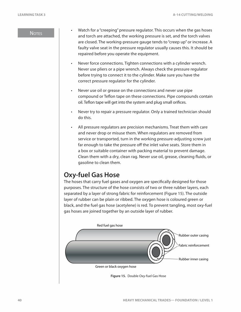
Oxy-fuel Gas HoseThe hoses that carry fuel gases and oxygen are speci�cally designed for those purposes. The structure of the hose consists of two or three rubber layers, each separated by a layer of strong fabric for reinforcement (Figure 15). The outside layer of rubber can be plain or ribbed. The oxygen hose is coloured green or black, and the fuel gas hose (acetylene) is red. To prevent tangling, most oxy-fuel gas hoses are joined together by an outside layer of rubber.
Red fuel gas hose
Green or black oxygen hose
Rubber outer casing
Rubber inner casing
Fabric reinforcement
Figure 15. Double Oxy-fuel Gas Hose
HEAVY MECHANICAL TRADES— FOUNDATION / LEVEL 1 41
NOTES
A-14 CUTTING/WELDING LEARNING TASK 3
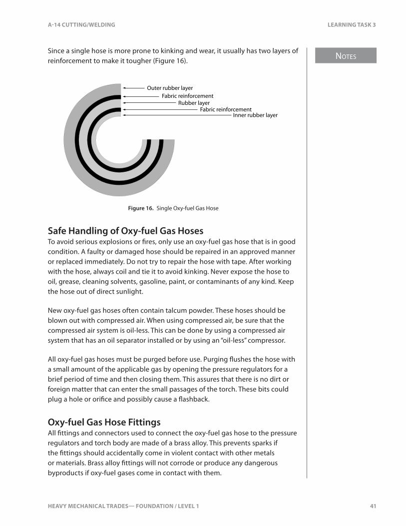
Since a single hose is more prone to kinking and wear, it usually has two layers of reinforcement to make it tougher (Figure 16).
Outer rubber layerFabric reinforcement
Fabric reinforcementInner rubber layer
Rubber layer
Figure 16. Single Oxy-fuel Gas Hose
Safe Handling of Oxy-fuel Gas HosesTo avoid serious explosions or �res, only use an oxy-fuel gas hose that is in good condition. A faulty or damaged hose should be repaired in an approved manner or replaced immediately. Do not try to repair the hose with tape. After working with the hose, always coil and tie it to avoid kinking. Never expose the hose to oil, grease, cleaning solvents, gasoline, paint, or contaminants of any kind. Keep the hose out of direct sunlight.
New oxy-fuel gas hoses often contain talcum powder. These hoses should be blown out with compressed air. When using compressed air, be sure that the compressed air system is oil-less. This can be done by using a compressed air system that has an oil separator installed or by using an “oil-less” compressor.
All oxy-fuel gas hoses must be purged before use. Purging �ushes the hose with a small amount of the applicable gas by opening the pressure regulators for a brief period of time and then closing them. This assures that there is no dirt or foreign matter that can enter the small passages of the torch. These bits could plug a hole or ori�ce and possibly cause a �ashback.
Oxy-fuel Gas Hose FittingsAll �ttings and connectors used to connect the oxy-fuel gas hose to the pressure regulators and torch body are made of a brass alloy. This prevents sparks if the �ttings should accidentally come in violent contact with other metals or materials. Brass alloy �ttings will not corrode or produce any dangerous byproducts if oxy-fuel gases come in contact with them.
NOTES
42 HEAVY MECHANICAL TRADES— FOUNDATION / LEVEL 1
LEARNING TASK 3 A-14 CUTTING/WELDING
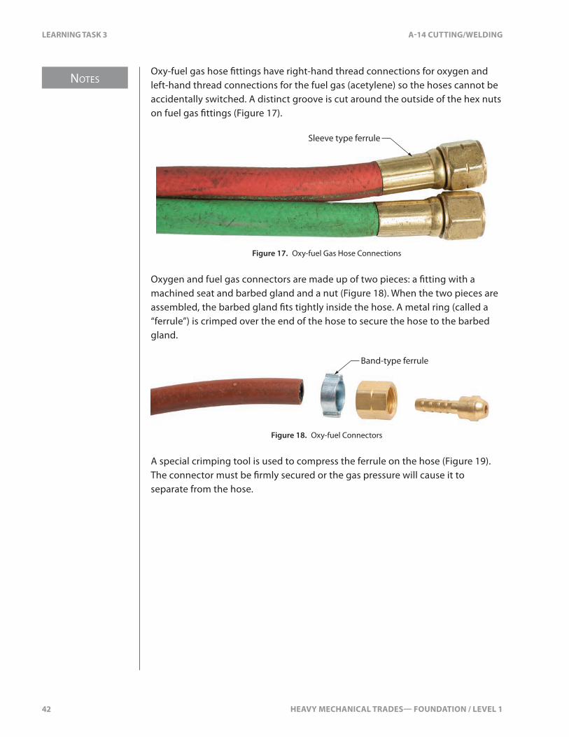
Oxy-fuel gas hose �ttings have right-hand thread connections for oxygen and left-hand thread connections for the fuel gas (acetylene) so the hoses cannot be accidentally switched. A distinct groove is cut around the outside of the hex nuts on fuel gas �ttings (Figure 17).
Sleeve type ferrule
Figure 17. Oxy-fuel Gas Hose Connections
Oxygen and fuel gas connectors are made up of two pieces: a �tting with a machined seat and barbed gland and a nut (Figure 18). When the two pieces are assembled, the barbed gland �ts tightly inside the hose. A metal ring (called a “ferrule”) is crimped over the end of the hose to secure the hose to the barbed gland.
Band-type ferrule
Figure 18. Oxy-fuel Connectors
A special crimping tool is used to compress the ferrule on the hose (Figure 19). The connector must be �rmly secured or the gas pressure will cause it to separate from the hose.

HEAVY MECHANICAL TRADES— FOUNDATION / LEVEL 1 43
NOTES
A-14 CUTTING/WELDING LEARNING TASK 3
Figure 19. Ferrule Crimping Tools
Hose couplings can be used to connect two lengths of oxy-fuel gas hose (Figure 20). These couplings or splicers can also be inserted in a hose where a damaged section of the hose has been removed.
Figure 20. Hose Splice Coupling
Never use copper or red brass for �ttings or tubing on acetylene gas systems. Acetylene gas reacts with copper to form acetylide, a residue that is even more unstable than acetylene. The slightest jolt can cause an explosion. Fire will most certainly result, causing injury or death. Only �ttings made of yellow brass, iron, or steel can be used on acetylene gas systems.
Oxy-fuel Gas-cutting Torches, Cutting Tips, and Heating TipsBasic Torch FeaturesAlthough there are di�erent types of oxy-fuel gas torches, all have certain elements in common (Figure 21). The most distinctive feature of a cutting torch is the cutting oxygen control lever. Depressing this lever fully releases a �ow of cutting oxygen. Cutting torches also have two hose connections to supply the oxygen and fuel gas to the torch. The oxygen hose connection has right-hand threads and the fuel gas connection has left-hand threads.
NOTES
44 HEAVY MECHANICAL TRADES— FOUNDATION / LEVEL 1
LEARNING TASK 3 A-14 CUTTING/WELDING
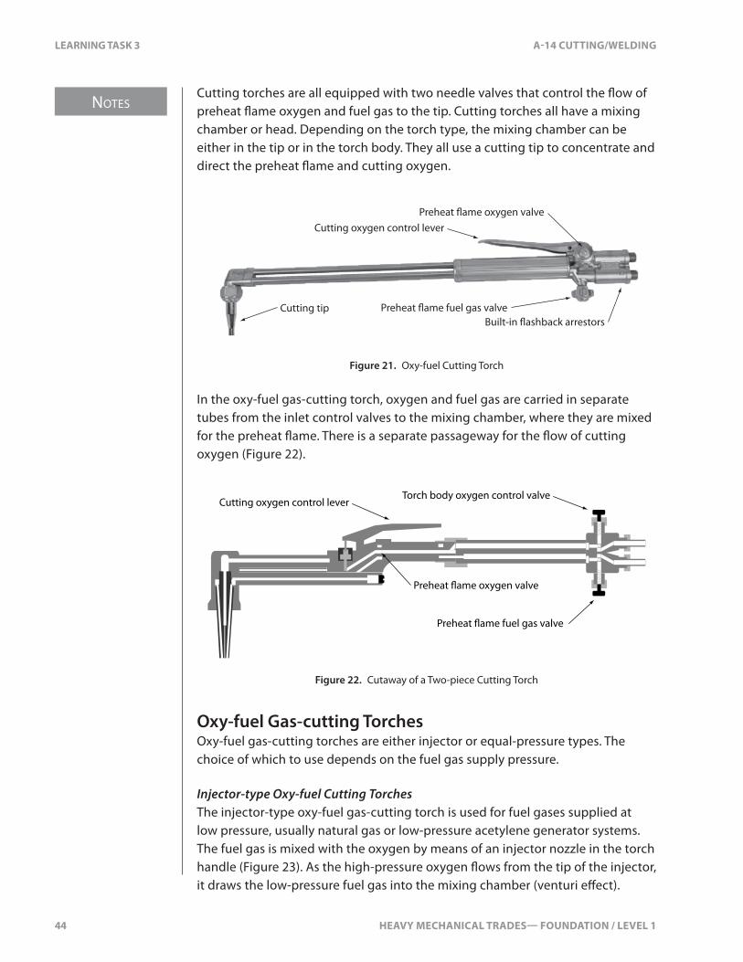
Cutting torches are all equipped with two needle valves that control the �ow of preheat �ame oxygen and fuel gas to the tip. Cutting torches all have a mixing chamber or head. Depending on the torch type, the mixing chamber can be either in the tip or in the torch body. They all use a cutting tip to concentrate and direct the preheat �ame and cutting oxygen.
Cutting tip
Cutting oxygen control leverPreheat �ame oxygen valve
Preheat �ame fuel gas valveBuilt-in �ashback arrestors
Figure 21. Oxy-fuel Cutting Torch
In the oxy-fuel gas-cutting torch, oxygen and fuel gas are carried in separate tubes from the inlet control valves to the mixing chamber, where they are mixed for the preheat �ame. There is a separate passageway for the �ow of cutting oxygen (Figure 22).
Cutting oxygen control lever
Preheat �ame oxygen valve
Torch body oxygen control valve
Preheat �ame fuel gas valve
Figure 22. Cutaway of a Two-piece Cutting Torch
Oxy-fuel Gas-cutting TorchesOxy-fuel gas-cutting torches are either injector or equal-pressure types. The choice of which to use depends on the fuel gas supply pressure.
Injector-type Oxy-fuel Cutting TorchesThe injector-type oxy-fuel gas-cutting torch is used for fuel gases supplied at low pressure, usually natural gas or low-pressure acetylene generator systems. The fuel gas is mixed with the oxygen by means of an injector nozzle in the torch handle (Figure 23). As the high-pressure oxygen �ows from the tip of the injector, it draws the low-pressure fuel gas into the mixing chamber (venturi e�ect).
HEAVY MECHANICAL TRADES— FOUNDATION / LEVEL 1 45
NOTES
A-14 CUTTING/WELDING LEARNING TASK 3
High-pressure oxygen
Low-pressure fuel gas
Injector
Mixing chamber
Figure 23. Injector Torch
Equal Pressure-type Oxy-fuel Gas-cutting TorchThe equal pressure-type oxy-fuel gas-cutting torch is more common than the injector type. It is designed for use with fuel gases supplied at higher pressures.
One-piece Oxy-fuel Gas-cutting TorchThe one-piece oxy-fuel gas-cutting torch is designed to be used only for oxy- fuel gas-cutting processes.
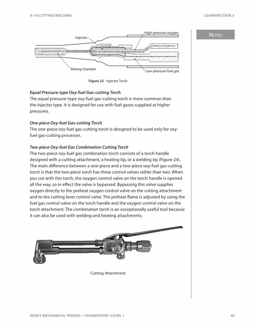
Two-piece Oxy-fuel Gas Combination Cutting TorchThe two-piece oxy-fuel gas combination torch consists of a torch handle designed with a cutting attachment, a heating tip, or a welding tip (Figure 24). The main di�erence between a one-piece and a two-piece oxy-fuel gas-cutting torch is that the two-piece torch has three control valves rather than two. When you cut with this torch, the oxygen control valve on the torch handle is opened all the way, so in e�ect the valve is bypassed. Bypassing this valve supplies oxygen directly to the preheat oxygen control valve on the cutting attachment and to the cutting lever control valve. The preheat �ame is adjusted by using the fuel gas control valve on the torch handle and the oxygen control valve on the torch attachment. The combination torch is an exceptionally useful tool because it can also be used with welding and heating attachments.
Cutting Attachment

NOTES
46 HEAVY MECHANICAL TRADES— FOUNDATION / LEVEL 1
LEARNING TASK 3 A-14 CUTTING/WELDING
Torch Body
Figure 24. Two-piece Combination Torch
Oxy-fuel Gas-cutting TipsOxy-fuel gas-cutting tips are interchangeable with the same design of torch head. However, cutting tips made to one manufacturer’s design cannot be used with torches made to another manufacturer’s design.
Oxy-fuel gas-cutting tips are precision tools that should never be subjected to abuse. The tip can become damaged by extreme temperature, by dropping the torch, or even by setting it down roughly on a workbench top. When tips are not attached to the cutting torch, they should be stored in their original containers or in a special storage rack.
Oxy-fuel gas cutting tips have seats designed to match those in the head of the cutting torch (Figure 25). Before installing the cutting tip, you should visually inspect the seats, checking for dirt or damage to the seat surfaces. The tip nut should always be tightened snugly with a wrench to prevent gas leakage. All cutting tips have pre-heat �ame ori�ces, usually arranged in an outer circle with a cutting oxygen ori�ce in the centre.
Cutting jet oriface
Preheat �ame holes
Cutting tip Torch head
Seats
Cutting tip nut
Figure 25. Injector Torch

HEAVY MECHANICAL TRADES— FOUNDATION / LEVEL 1 47
NOTES
A-14 CUTTING/WELDING LEARNING TASK 3
Cutting Tip SizesOxy-fuel gas cutting tips are available in several sizes based on the thickness of the metal to be cut. The diameters of the preheat �ame and cutting oxygen ori�ces increase as the thickness of metal to be cut increases. As the diameters increase, so do the designated tip size numbers. The numbers and the brand name are normally stamped on the cutting tip for easy identi�cation (Figure 26).
Figure 26. Cutting Tip Labelling
The following table shows examples of cutting tip sizes and cutting pressures as they relate to the various metal thicknesses (Figure 27). Note that the pressure settings for oxygen and acetylene are listed. Tip size designations and pressure settings can vary with each equipment manufacturer.
Metal
thickness
Tip size
number
Cutting pressures
Oxygen (min.–max. psi) Acetylene (min.–max. psi)
3 mm (1⁄8") 000 20–25 3–5
6 mm (1⁄4") 00 20–25 3–5
10 mm (3⁄8") 0 25–30 3–5
13 mm (1⁄2") 0 30–35 3–5
19 mm (3⁄4") 1 30–35 3–5
25 mm (1") 2 35–40 3–6
38 mm (11⁄2") 2 40–45 3–7
51 mm (2") 3 40–45 4–9
64 mm (21⁄2") 3 45–50 4–10
76 mm (3") 4 40–50 5–10
102 mm (4") 5 45–55 5–12
127 mm (5") 5 50–55 5–13
152 mm (6") 6 45–55 7–13
203 mm (8") 6 55–65 7–14
254 mm (10") 7 55–65 10–15
305 mm (12") 8 60–70 10–15
Figure 27. Cutting Tip Size Chart
NOTES
48 HEAVY MECHANICAL TRADES— FOUNDATION / LEVEL 1
LEARNING TASK 3 A-14 CUTTING/WELDING
Types of Oxy-fuel Cutting TipsThere are many cutting tip designs available. Your choice will depend on the use of the cutting tip and the type of fuel gas. Each fuel gas, such as acetylene, methylacetylene-propadiene (Mapp®), propane, natural gas, or propylene, requires a specially designed tip for cutting. A cutting torch and tip assembly must never be used with a fuel gas for which it was not intended.
Methylacetylene-propadiene (Mapp®), propane, and natural gas all require more oxygen than acetylene to produce a neutral �ame. Therefore, the mixing chambers and preheat �ame ori�ces must be adjusted to accommodate this increase in oxygen requirements. Cutting tips for fuel gases other than acetylene are often two-piece in construction to accommodate the large volume of oxygen and fuel gas burning characteristics.
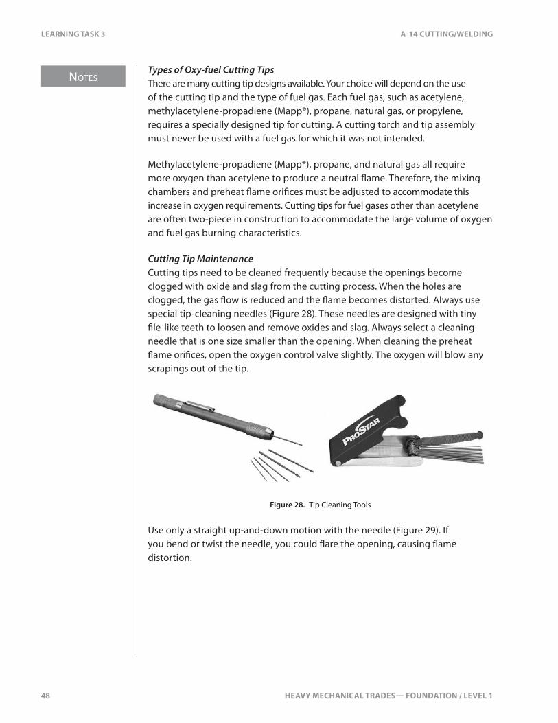
Cutting Tip MaintenanceCutting tips need to be cleaned frequently because the openings become clogged with oxide and slag from the cutting process. When the holes are clogged, the gas �ow is reduced and the �ame becomes distorted. Always use special tip-cleaning needles (Figure 28). These needles are designed with tiny �le-like teeth to loosen and remove oxides and slag. Always select a cleaning needle that is one size smaller than the opening. When cleaning the preheat �ame ori�ces, open the oxygen control valve slightly. The oxygen will blow any scrapings out of the tip.
Figure 28. Tip Cleaning Tools
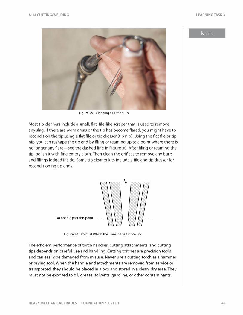
Use only a straight up-and-down motion with the needle (Figure 29). If you bend or twist the needle, you could �are the opening, causing �ame distortion.
HEAVY MECHANICAL TRADES— FOUNDATION / LEVEL 1 49
NOTES
A-14 CUTTING/WELDING LEARNING TASK 3
Figure 29. Cleaning a Cutting Tip
Most tip cleaners include a small, �at, �le-like scraper that is used to remove any slag. If there are worn areas or the tip has become �ared, you might have to recondition the tip using a �at �le or tip dresser (tip nip). Using the �at �le or tip nip, you can reshape the tip end by �ling or reaming up to a point where there is no longer any �are—see the dashed line in Figure 30. After �ling or reaming the tip, polish it with �ne emery cloth. Then clean the ori�ces to remove any burrs and �lings lodged inside. Some tip cleaner kits include a �le and tip dresser for reconditioning tip ends.
Do not �le past this point
Figure 30. Point at Which the Flare in the Ori�ce Ends
The e�cient performance of torch handles, cutting attachments, and cutting tips depends on careful use and handling. Cutting torches are precision tools and can easily be damaged from misuse. Never use a cutting torch as a hammer or prying tool. When the handle and attachments are removed from service or transported, they should be placed in a box and stored in a clean, dry area. They must not be exposed to oil, grease, solvents, gasoline, or other contaminants.

NOTES
50 HEAVY MECHANICAL TRADES— FOUNDATION / LEVEL 1
LEARNING TASK 3 A-14 CUTTING/WELDING
Special Purpose TipsIn addition to tips for general cutting duties, there are tips designed for certain special purposes. Two of the most common are:
• rivet-cutting tips• gouging tips
When using rivet-cutting tips and gouging tips (Figure 31), you must make sure that your working pressures are correct and you do not exceed the acetylene draw limits. Exceeding draw limits will result in drawing acetone from the acetylene cylinder, which will a�ect the fuel gas �ow and result in back�res and �ashbacks.
Rivet-cutting tips are used for cutting or washing heads o� rivets and bolts. The �at part of the tip lies on the base metal, thus preventing the base metal from being burned as the rivet or nut is washed o�.
Figure 31. Rivet-cutting Tip
Gouging tips are used for removing tack welds, weld defects, and casting defects (Figure 32).
Figure 32. Gouging Tip
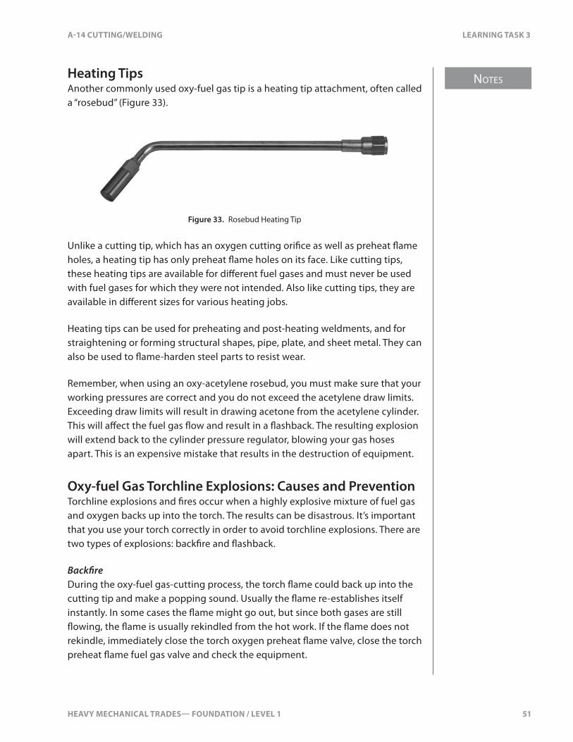
HEAVY MECHANICAL TRADES— FOUNDATION / LEVEL 1 51
NOTES
A-14 CUTTING/WELDING LEARNING TASK 3
Heating TipsAnother commonly used oxy-fuel gas tip is a heating tip attachment, often called a “rosebud” (Figure 33).
Figure 33. Rosebud Heating Tip
Unlike a cutting tip, which has an oxygen cutting ori�ce as well as preheat �ame holes, a heating tip has only preheat �ame holes on its face. Like cutting tips, these heating tips are available for di�erent fuel gases and must never be used with fuel gases for which they were not intended. Also like cutting tips, they are available in di�erent sizes for various heating jobs.
Heating tips can be used for preheating and post-heating weldments, and for straightening or forming structural shapes, pipe, plate, and sheet metal. They can also be used to �ame-harden steel parts to resist wear.
Remember, when using an oxy-acetylene rosebud, you must make sure that your working pressures are correct and you do not exceed the acetylene draw limits. Exceeding draw limits will result in drawing acetone from the acetylene cylinder. This will a�ect the fuel gas �ow and result in a �ashback. The resulting explosion will extend back to the cylinder pressure regulator, blowing your gas hoses apart. This is an expensive mistake that results in the destruction of equipment.
Oxy-fuel Gas Torchline Explosions: Causes and PreventionTorchline explosions and �res occur when a highly explosive mixture of fuel gas and oxygen backs up into the torch. The results can be disastrous. It’s important that you use your torch correctly in order to avoid torchline explosions. There are two types of explosions: back�re and �ashback.
Back�reDuring the oxy-fuel gas-cutting process, the torch �ame could back up into the cutting tip and make a popping sound. Usually the �ame re-establishes itself instantly. In some cases the �ame might go out, but since both gases are still �owing, the �ame is usually rekindled from the hot work. If the �ame does not rekindle, immediately close the torch oxygen preheat �ame valve, close the torch preheat �ame fuel gas valve and check the equipment.
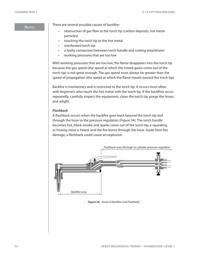
NOTES
52 HEAVY MECHANICAL TRADES— FOUNDATION / LEVEL 1
LEARNING TASK 3 A-14 CUTTING/WELDING
There are several possible causes of back�re:
• obstruction of gas �ow at the torch tip (carbon deposits, hot metal particles)
• touching the torch tip to the hot metal• overheated torch tip• a faulty connection between torch handle and cutting attachment• working pressures that are too low
With working pressures that are too low, the �ame disappears into the torch tip because the gas speed (the speed at which the mixed gases come out of the torch tip) is not great enough. The gas speed must always be greater than the speed of propagation (the speed at which the �ame travels toward the torch tip).
Back�re is momentary and is restricted to the torch tip. It occurs most often with beginners who touch the hot metal with the torch tip. If the back�res occur repeatedly, carefully inspect the equipment, clean the torch tip, purge the hoses, and relight.
FlashbackA �ashback occurs when the back�re goes back beyond the torch tip and through the hose to the pressure regulators (Figure 34). The torch handle becomes hot, black smoke and sparks come out of the torch tip, a squealing or hissing noise is heard, and the �re burns through the hose. Aside from �re damage, a �ashback could cause an explosion.
Back�re area
Flashback area (through to cylinder pressure regulator)
Figure 34. Areas of Back�re and Flashback

HEAVY MECHANICAL TRADES— FOUNDATION / LEVEL 1 53
NOTES
A-14 CUTTING/WELDING LEARNING TASK 3
The causes of a �ashback are:
• Incorrect working pressures.• Incorrect adjustment of the torch oxygen and fuel gas control valves.• Grossly unequal oxygen and fuel gas working pressures. The higher-
pressure gas can back up into the lower-pressure line and produce a �ashback.
• A clogged tip, along with too high oxygen pressure.• Igniting the torch before purging the hoses. A torch that has been sitting
idle for a while might well have an explosive mixture present in one hose.
To help prevent back�res and �ashbacks, make sure that the valves on the torch and pressure regulators are working properly. The tip should have clear, undamaged ori�ces. Flashback arrestors must be used.
If you have a �ashback, you must stop the �ame immediately before an explosion occurs. Shut down the torch preheat �ame gas control valves and the cylinder valves immediately. The torch preheat �ame oxygen control valve must be shut o� before the torch preheat �ame fuel gas control valve.
A �ashback indicates that something is radically wrong with the setup. Before you reignite the torch, check all equipment to see if it is damaged. Replace any damaged equipment, purge each hose separately, and adjust working pressures. If a �ashback occurs again, stop using the equipment and have it serviced by quali�ed personnel.
Flashback ArrestorsThe best way to prevent �ashbacks and explosions is to keep the oxygen and fuel gases separated. Close the torch gas control valves when you’re not using the torch. Bleed gas hoses properly when you’re �nished using the equipment. You must regularly inspect the control valves on the torch and the cylinders, as well as the gauges on the pressure regulators. Remember, inspection cannot help you detect whether oxygen or fuel gases are �owing in reverse inside the torch or hoses.
A device called a “�ashback arrestor” (Figure 35) is designed to respond to the pressure of a �ashback by immediately stopping the progress of the �ame burning back into the hoses and stopping the reverse �ow of gas. A �ashback arrestor also serves as a reverse-�ow check valve, automatically stopping the reverse �ow of the gas the moment it starts. Reverse-�ow check valves are available without �ashback capability. These reverse-�ow check valves are often installed in the connections between the torch and the gas hoses. But it is strongly recommended that a proper �ashback arrestor be installed at this location. WorkSafeBC regulations require that �ashback arrestors be properly installed between the torch control valves and the cylinder pressure regulators.
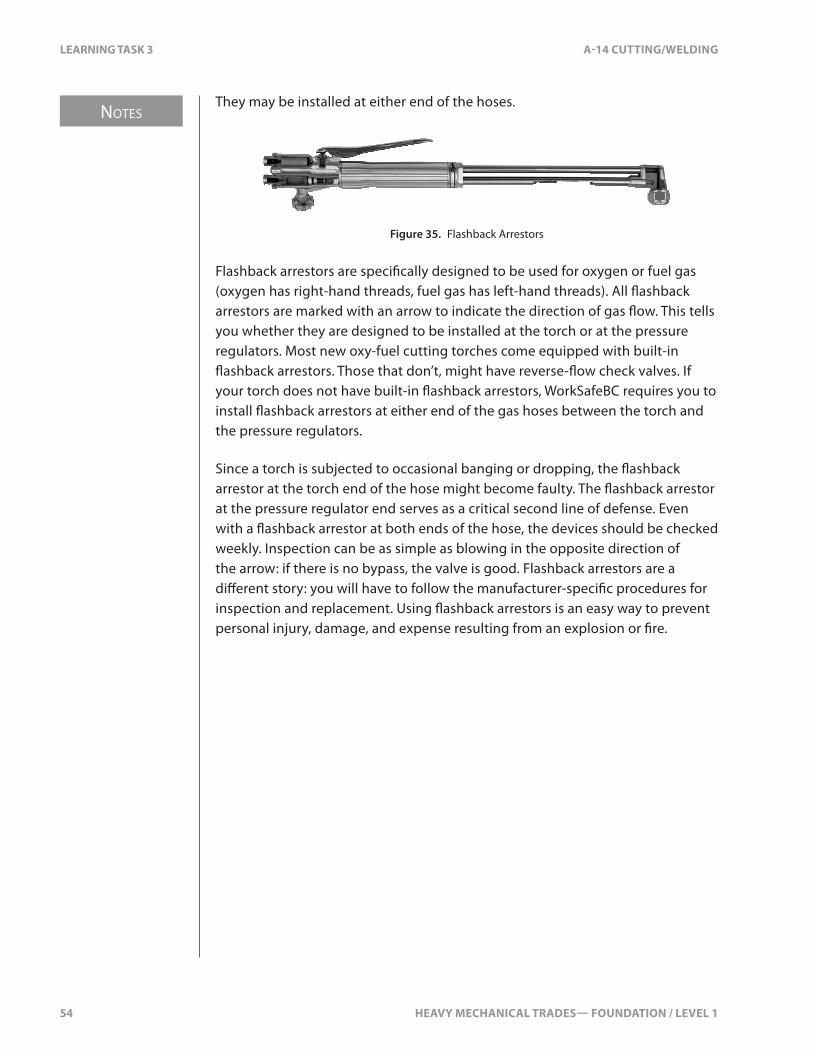
NOTES
54 HEAVY MECHANICAL TRADES— FOUNDATION / LEVEL 1
LEARNING TASK 3 A-14 CUTTING/WELDING
They may be installed at either end of the hoses.
Figure 35. Flashback Arrestors
Flashback arrestors are speci�cally designed to be used for oxygen or fuel gas (oxygen has right-hand threads, fuel gas has left-hand threads). All �ashback arrestors are marked with an arrow to indicate the direction of gas �ow. This tells you whether they are designed to be installed at the torch or at the pressure regulators. Most new oxy-fuel cutting torches come equipped with built-in �ashback arrestors. Those that don’t, might have reverse-�ow check valves. If your torch does not have built-in �ashback arrestors, WorkSafeBC requires you to install �ashback arrestors at either end of the gas hoses between the torch and the pressure regulators.
Since a torch is subjected to occasional banging or dropping, the �ashback arrestor at the torch end of the hose might become faulty. The �ashback arrestor at the pressure regulator end serves as a critical second line of defense. Even with a �ashback arrestor at both ends of the hose, the devices should be checked weekly. Inspection can be as simple as blowing in the opposite direction of the arrow: if there is no bypass, the valve is good. Flashback arrestors are a di�erent story: you will have to follow the manufacturer-speci�c procedures for inspection and replacement. Using �ashback arrestors is an easy way to prevent personal injury, damage, and expense resulting from an explosion or �re.

HEAVY MECHANICAL TRADES— FOUNDATION / LEVEL 1 55
A-14 CUTTING/WELDING SELF TEST 3
SELF TEST 3
1. What material are the acetylene �ttings are made of?
a. copper or red brass
b. steel, iron, or yellow brass
c. red brass or steel
d. iron, red brass, or yellow brass
2. What is the maximum safe working pressure for acetylene?
a. 103 kPa (15 psi)
b. 138 kPa (20 psi)
c. 193 kPa (28 psi)
d. 345 kPa (50 psi)

56 HEAVY MECHANICAL TRADES— FOUNDATION / LEVEL 1

HEAVY MECHANICAL TRADES— FOUNDATION / LEVEL 1 57
NOTES
A-14 CUTTING/WELDING LEARNING TASK 4
LEARNING TASK 4
Correct Procedures to Assemble, Ignite, Shut Down, and Disassemble a Portable Oxy-acetylene Unit
How to Assemble a Portable Oxy-acetylene UnitAlthough many shops have a manifold system, portable oxy-fuel equipment is commonly used in the welding trades. Portable units can be found in many job settings, especially on industrial maintenance and construction sites or in fabrication and repair shops, where portability is required.
Portable oxy-fuel units can be used with a variety of fuel gases, as discussed earlier. Acetylene has some advantages over other fuel gases due to its higher �ame temperature and lower consumption of oxygen. Therefore, it’s the most common fuel gas used with the portable oxy-fuel units.
The assembly and operating procedures for oxy-fuel and oxy-acetylene equipment are basically the same. This Learning Task will only discuss portable oxy-acetylene equipment.
The steps to follow when assembling, igniting, shutting down, and disassembling oxy-acetylene equipment must be done in the correct order. Not following these steps precisely can result in personal injury and explosion.
Steps to Assemble a Portable Oxy-Acetylene UnitWhen assembling a portable oxy-acetylene unit, you must follow these steps:
1. secure the cylinders2. remove the cylinder caps3. crack the cylinder valves4. attach the cylinder pressure regulators5. install the �ashback arrestors6. connect the gas hoses7. open the cylinder valves8. purge the cylinder pressure regulators and gas hoses9. connect the cutting torch10. set the working pressure11. purge the closed system12. check the system for leaks

NOTES
58 HEAVY MECHANICAL TRADES— FOUNDATION / LEVEL 1
LEARNING TASK 4 A-14 CUTTING/WELDING
1. Secure the Cylinders in an Upright PositionA light chain is commonly used to secure oxy-fuel gas cylinders to a portable cart so they do not tip over or get jarred (Figure 1). The cylinder cart is designed to roll easily when tilted back on its wheels, yet be stable and secure when stationary.
Figure 1. Cylinders Mounted Upright
2. Remove the Caps Covering the Cylinder ValvesTurn the cylinder cap counter-clockwise to remove it (Figure 2). Always replace the cylinder cap when transporting an oxy-fuel gas cylinder and when the cylinder is not in service.
Cap over cylinder valve
Figure 2. Removing the Caps
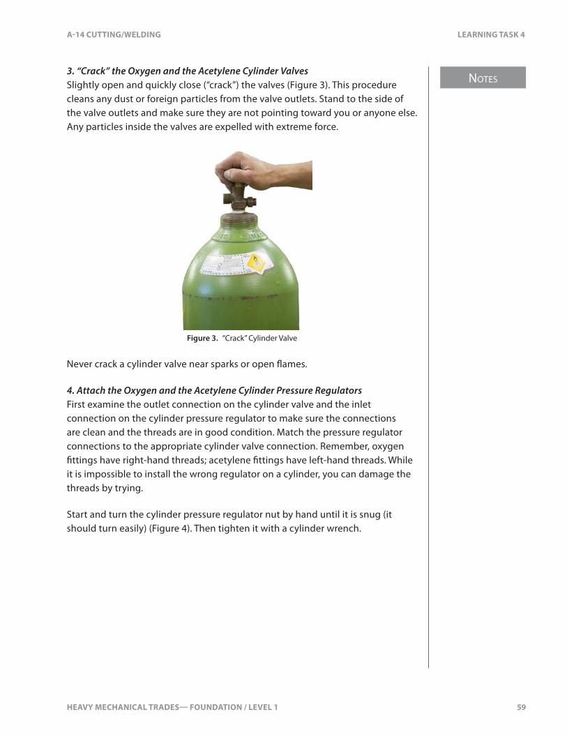
HEAVY MECHANICAL TRADES— FOUNDATION / LEVEL 1 59
NOTES
A-14 CUTTING/WELDING LEARNING TASK 4
3. “Crack” the Oxygen and the Acetylene Cylinder ValvesSlightly open and quickly close (“crack”) the valves (Figure 3). This procedure cleans any dust or foreign particles from the valve outlets. Stand to the side of the valve outlets and make sure they are not pointing toward you or anyone else. Any particles inside the valves are expelled with extreme force.
Figure 3. “Crack” Cylinder Valve
Never crack a cylinder valve near sparks or open �ames.
4. Attach the Oxygen and the Acetylene Cylinder Pressure RegulatorsFirst examine the outlet connection on the cylinder valve and the inlet connection on the cylinder pressure regulator to make sure the connections are clean and the threads are in good condition. Match the pressure regulator connections to the appropriate cylinder valve connection. Remember, oxygen �ttings have right-hand threads; acetylene �ttings have left-hand threads. While it is impossible to install the wrong regulator on a cylinder, you can damage the threads by trying.
Start and turn the cylinder pressure regulator nut by hand until it is snug (it should turn easily) (Figure 4). Then tighten it with a cylinder wrench.
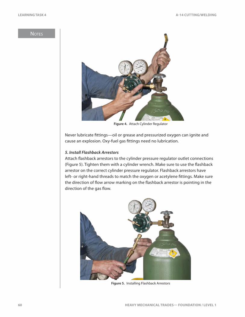
NOTES
60 HEAVY MECHANICAL TRADES— FOUNDATION / LEVEL 1
LEARNING TASK 4 A-14 CUTTING/WELDING
Figure 4. Attach Cylinder Regulator
Never lubricate �ttings—oil or grease and pressurized oxygen can ignite and cause an explosion. Oxy-fuel gas �ttings need no lubrication.
5. Install Flashback ArrestorsAttach �ashback arrestors to the cylinder pressure regulator outlet connections (Figure 5). Tighten them with a cylinder wrench. Make sure to use the �ashback arrestor on the correct cylinder pressure regulator. Flashback arrestors have left- or right-hand threads to match the oxygen or acetylene �ttings. Make sure the direction of �ow arrow marking on the �ashback arrestor is pointing in the direction of the gas �ow.
Figure 5. Installing Flashback Arrestors
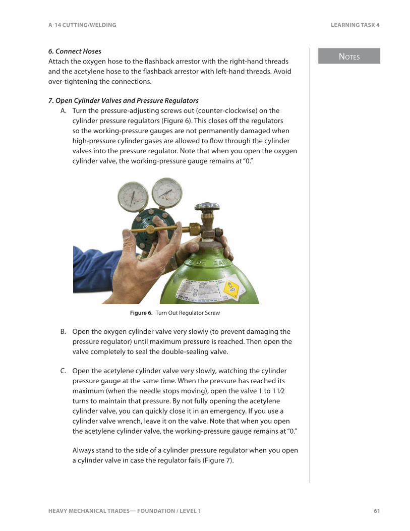
HEAVY MECHANICAL TRADES— FOUNDATION / LEVEL 1 61
NOTES
A-14 CUTTING/WELDING LEARNING TASK 4
6. Connect HosesAttach the oxygen hose to the �ashback arrestor with the right-hand threads and the acetylene hose to the �ashback arrestor with left-hand threads. Avoid over-tightening the connections.
7. Open Cylinder Valves and Pressure RegulatorsA. Turn the pressure-adjusting screws out (counter-clockwise) on the
cylinder pressure regulators (Figure 6). This closes o� the regulators so the working-pressure gauges are not permanently damaged when high-pressure cylinder gases are allowed to �ow through the cylinder valves into the pressure regulator. Note that when you open the oxygen cylinder valve, the working-pressure gauge remains at “0.”
Figure 6. Turn Out Regulator Screw
B. Open the oxygen cylinder valve very slowly (to prevent damaging the pressure regulator) until maximum pressure is reached. Then open the valve completely to seal the double-sealing valve.
C. Open the acetylene cylinder valve very slowly, watching the cylinder pressure gauge at the same time. When the pressure has reached its maximum (when the needle stops moving), open the valve 1 to 11⁄2 turns to maintain that pressure. By not fully opening the acetylene cylinder valve, you can quickly close it in an emergency. If you use a cylinder valve wrench, leave it on the valve. Note that when you open the acetylene cylinder valve, the working-pressure gauge remains at “0.”
Always stand to the side of a cylinder pressure regulator when you open a cylinder valve in case the regulator fails (Figure 7).
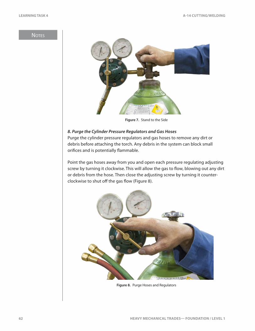
NOTES
62 HEAVY MECHANICAL TRADES— FOUNDATION / LEVEL 1
LEARNING TASK 4 A-14 CUTTING/WELDING
Figure 7. Stand to the Side
8. Purge the Cylinder Pressure Regulators and Gas HosesPurge the cylinder pressure regulators and gas hoses to remove any dirt or debris before attaching the torch. Any debris in the system can block small ori�ces and is potentially �ammable.
Point the gas hoses away from you and open each pressure regulating adjusting screw by turning it clockwise. This will allow the gas to �ow, blowing out any dirt or debris from the hose. Then close the adjusting screw by turning it counter-clockwise to shut o� the gas �ow (Figure 8).
Figure 8. Purge Hoses and Regulators
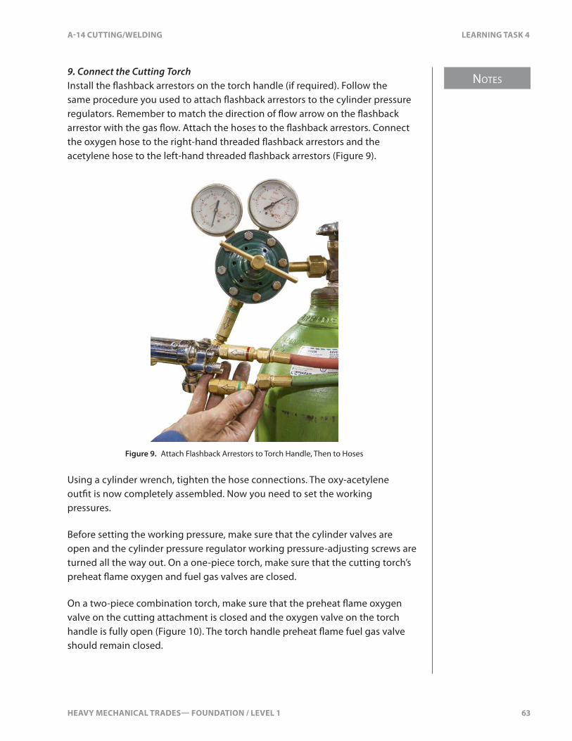
HEAVY MECHANICAL TRADES— FOUNDATION / LEVEL 1 63
NOTES
A-14 CUTTING/WELDING LEARNING TASK 4
9. Connect the Cutting TorchInstall the �ashback arrestors on the torch handle (if required). Follow the same procedure you used to attach �ashback arrestors to the cylinder pressure regulators. Remember to match the direction of �ow arrow on the �ashback arrestor with the gas �ow. Attach the hoses to the �ashback arrestors. Connect the oxygen hose to the right-hand threaded �ashback arrestors and the acetylene hose to the left-hand threaded �ashback arrestors (Figure 9).
Figure 9. Attach Flashback Arrestors to Torch Handle, Then to Hoses
Using a cylinder wrench, tighten the hose connections. The oxy-acetylene out�t is now completely assembled. Now you need to set the working pressures.
Before setting the working pressure, make sure that the cylinder valves are open and the cylinder pressure regulator working pressure-adjusting screws are turned all the way out. On a one-piece torch, make sure that the cutting torch’s preheat �ame oxygen and fuel gas valves are closed.
On a two-piece combination torch, make sure that the preheat �ame oxygen valve on the cutting attachment is closed and the oxygen valve on the torch handle is fully open (Figure 10). The torch handle preheat �ame fuel gas valve should remain closed.
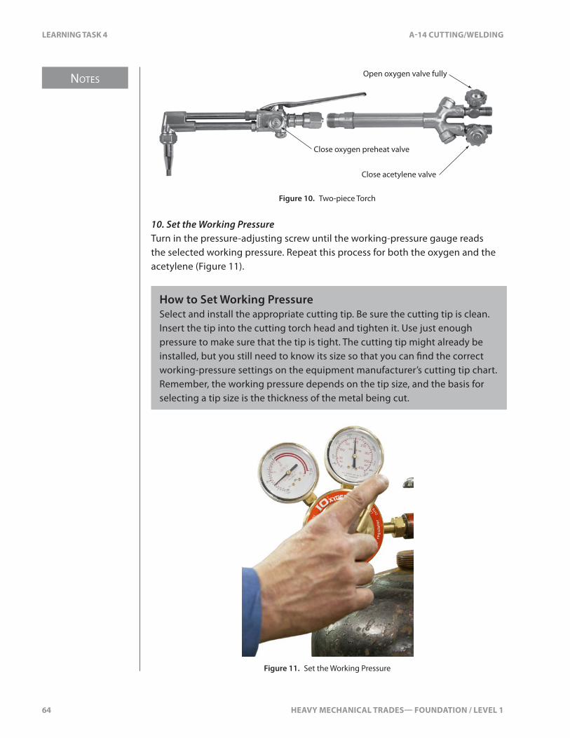
NOTES
64 HEAVY MECHANICAL TRADES— FOUNDATION / LEVEL 1
LEARNING TASK 4 A-14 CUTTING/WELDING
Close oxygen preheat valve
Close acetylene valve
Open oxygen valve fully
Figure 10. Two-piece Torch
10. Set the Working PressureTurn in the pressure-adjusting screw until the working-pressure gauge reads the selected working pressure. Repeat this process for both the oxygen and the acetylene (Figure 11).
How to Set Working PressureSelect and install the appropriate cutting tip. Be sure the cutting tip is clean. Insert the tip into the cutting torch head and tighten it. Use just enough pressure to make sure that the tip is tight. The cutting tip might already be installed, but you still need to know its size so that you can �nd the correct working-pressure settings on the equipment manufacturer’s cutting tip chart. Remember, the working pressure depends on the tip size, and the basis for selecting a tip size is the thickness of the metal being cut.
Figure 11. Set the Working Pressure
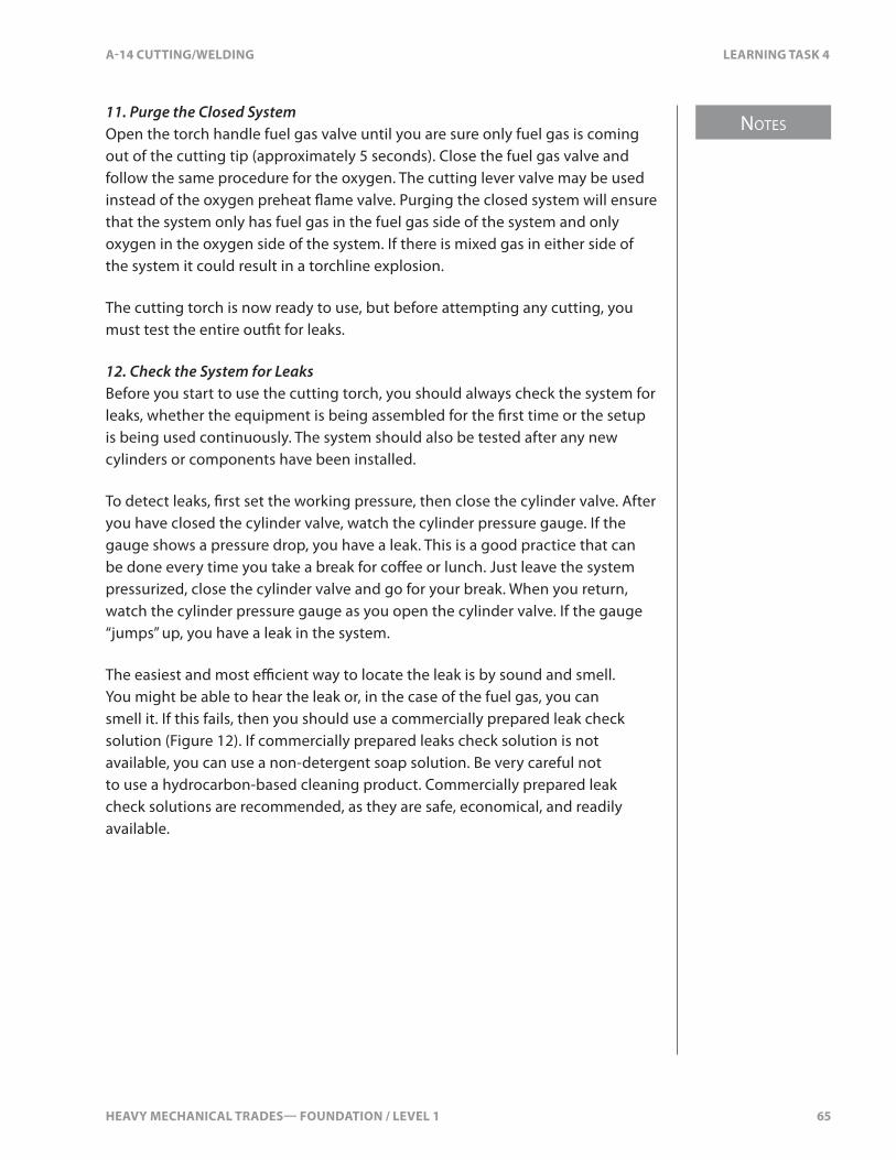
HEAVY MECHANICAL TRADES— FOUNDATION / LEVEL 1 65
NOTES
A-14 CUTTING/WELDING LEARNING TASK 4
11. Purge the Closed SystemOpen the torch handle fuel gas valve until you are sure only fuel gas is coming out of the cutting tip (approximately 5 seconds). Close the fuel gas valve and follow the same procedure for the oxygen. The cutting lever valve may be used instead of the oxygen preheat �ame valve. Purging the closed system will ensure that the system only has fuel gas in the fuel gas side of the system and only oxygen in the oxygen side of the system. If there is mixed gas in either side of the system it could result in a torchline explosion.
The cutting torch is now ready to use, but before attempting any cutting, you must test the entire out�t for leaks.
12. Check the System for LeaksBefore you start to use the cutting torch, you should always check the system for leaks, whether the equipment is being assembled for the �rst time or the setup is being used continuously. The system should also be tested after any new cylinders or components have been installed.
To detect leaks, �rst set the working pressure, then close the cylinder valve. After you have closed the cylinder valve, watch the cylinder pressure gauge. If the gauge shows a pressure drop, you have a leak. This is a good practice that can be done every time you take a break for co�ee or lunch. Just leave the system pressurized, close the cylinder valve and go for your break. When you return, watch the cylinder pressure gauge as you open the cylinder valve. If the gauge “jumps” up, you have a leak in the system.
The easiest and most e�cient way to locate the leak is by sound and smell. You might be able to hear the leak or, in the case of the fuel gas, you can smell it. If this fails, then you should use a commercially prepared leak check solution (Figure 12). If commercially prepared leaks check solution is not available, you can use a non-detergent soap solution. Be very careful not to use a hydrocarbon-based cleaning product. Commercially prepared leak check solutions are recommended, as they are safe, economical, and readily available.
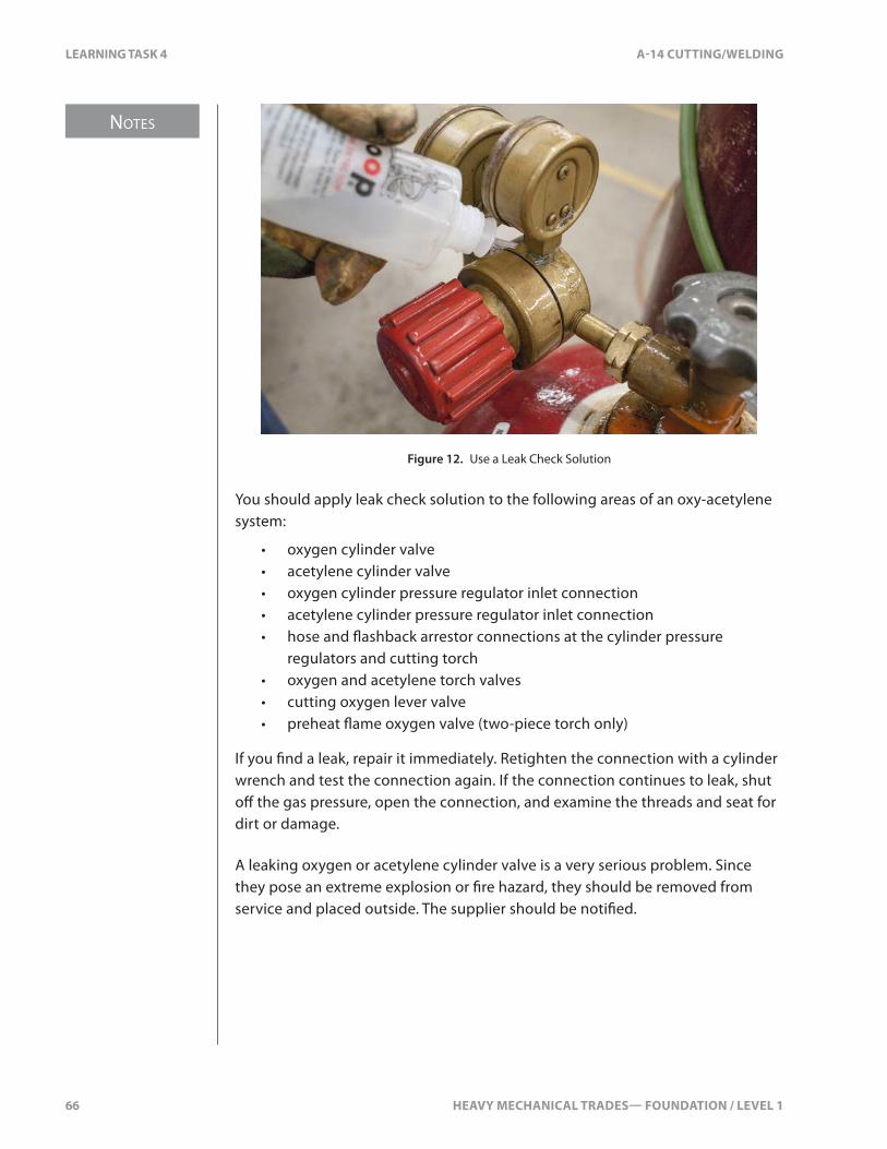
NOTES
66 HEAVY MECHANICAL TRADES— FOUNDATION / LEVEL 1
LEARNING TASK 4 A-14 CUTTING/WELDING
Figure 12. Use a Leak Check Solution
You should apply leak check solution to the following areas of an oxy-acetylene system:
• oxygen cylinder valve• acetylene cylinder valve• oxygen cylinder pressure regulator inlet connection• acetylene cylinder pressure regulator inlet connection• hose and �ashback arrestor connections at the cylinder pressure
regulators and cutting torch• oxygen and acetylene torch valves• cutting oxygen lever valve• preheat �ame oxygen valve (two-piece torch only)
If you �nd a leak, repair it immediately. Retighten the connection with a cylinder wrench and test the connection again. If the connection continues to leak, shut o� the gas pressure, open the connection, and examine the threads and seat for dirt or damage.
A leaking oxygen or acetylene cylinder valve is a very serious problem. Since they pose an extreme explosion or �re hazard, they should be removed from service and placed outside. The supplier should be noti�ed.

HEAVY MECHANICAL TRADES— FOUNDATION / LEVEL 1 67
NOTES
A-14 CUTTING/WELDING LEARNING TASK 4
How to Ignite and Adjust the Preheat FlameThe �int lighter, also known as a “spark lighter” or “striker,” is the only approved means of lighting an oxy-fuel gas torch. The steel cup on the �int lighter traps the fuel gas, and when the �int contacts the �le segment, it produces a spark that ignites the gas. The two models shown in Figure 13 are the most common type.
Figure 13. Flint Torch Lighters or Strikers
Never use matches, cigarette lighters (especially pressurized lighters), another torch, or hot metal to ignite your torch. Never keep pressurized lighters or matches in your pocket while you weld as they could ignite or explode and cause severe burns or personal injury.
Wear �re-retardant coveralls, leather welding gloves, CSA-approved boots, welding cap, and CSA-approved safety goggles. Be careful where you point the torch �ame and where you let the sparks and slag fall once you begin to cut.
Take a few minutes to familiarize yourself with the feel of the cutting torch and the striker with your gloves on. Practice using the striker; hold it about 25 mm (1 in.) from the end of the cutting tip (Figure 14).
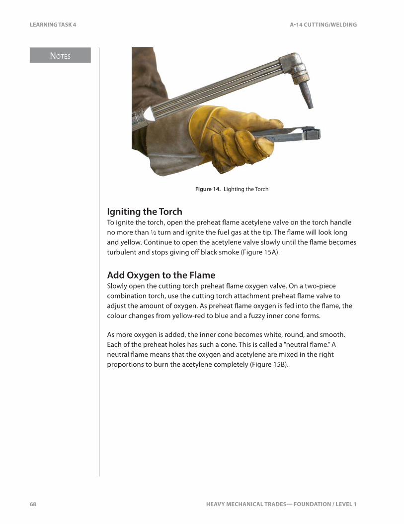
NOTES
68 HEAVY MECHANICAL TRADES— FOUNDATION / LEVEL 1
LEARNING TASK 4 A-14 CUTTING/WELDING
Figure 14. Lighting the Torch
Igniting the TorchTo ignite the torch, open the preheat �ame acetylene valve on the torch handle no more than 1⁄2 turn and ignite the fuel gas at the tip. The �ame will look long and yellow. Continue to open the acetylene valve slowly until the �ame becomes turbulent and stops giving o� black smoke (Figure 15A).
Add Oxygen to the FlameSlowly open the cutting torch preheat �ame oxygen valve. On a two-piece combination torch, use the cutting torch attachment preheat �ame valve to adjust the amount of oxygen. As preheat �ame oxygen is fed into the �ame, the colour changes from yellow-red to blue and a fuzzy inner cone forms.
As more oxygen is added, the inner cone becomes white, round, and smooth. Each of the preheat holes has such a cone. This is called a “neutral �ame.” A neutral �ame means that the oxygen and acetylene are mixed in the right proportions to burn the acetylene completely (Figure 15B).
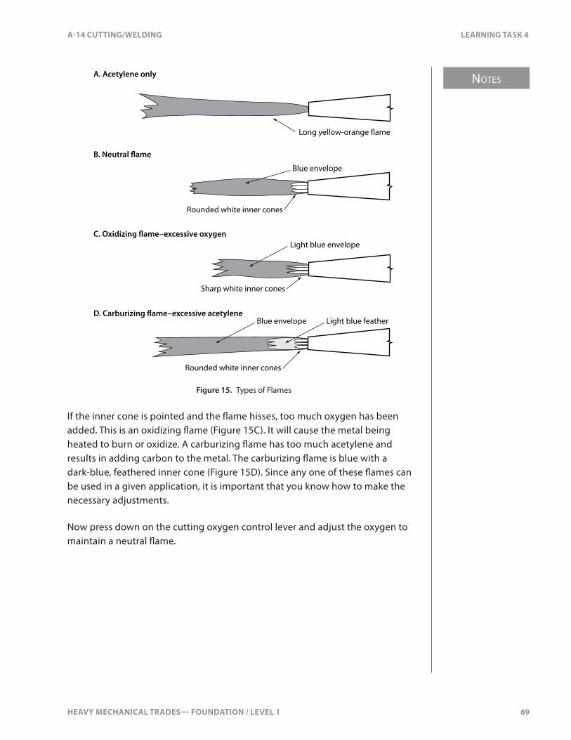
HEAVY MECHANICAL TRADES— FOUNDATION / LEVEL 1 69
NOTES
A-14 CUTTING/WELDING LEARNING TASK 4
A. Acetylene only
Long yellow-orange �ame
B. Neutral �ame
Blue envelope
Rounded white inner cones
C. Oxidizing �ame–excessive oxygenLight blue envelope
Sharp white inner cones
D. Carburizing �ame–excessive acetyleneLight blue featherBlue envelope
Rounded white inner cones
Figure 15. Types of Flames
If the inner cone is pointed and the �ame hisses, too much oxygen has been added. This is an oxidizing �ame (Figure 15C). It will cause the metal being heated to burn or oxidize. A carburizing �ame has too much acetylene and results in adding carbon to the metal. The carburizing �ame is blue with a dark-blue, feathered inner cone (Figure 15D). Since any one of these �ames can be used in a given application, it is important that you know how to make the necessary adjustments.
Now press down on the cutting oxygen control lever and adjust the oxygen to maintain a neutral �ame.
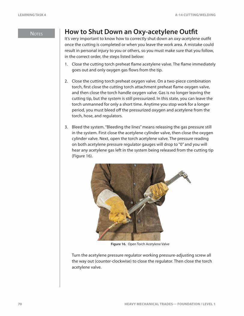
NOTES
70 HEAVY MECHANICAL TRADES— FOUNDATION / LEVEL 1
LEARNING TASK 4 A-14 CUTTING/WELDING
How to Shut Down an Oxy-acetylene Out�tIt’s very important to know how to correctly shut down an oxy-acetylene out�t once the cutting is completed or when you leave the work area. A mistake could result in personal injury to you or others, so you must make sure that you follow, in the correct order, the steps listed below:
1. Close the cutting torch preheat �ame acetylene valve. The �ame immediately goes out and only oxygen gas �ows from the tip.
2. Close the cutting torch preheat oxygen valve. On a two-piece combination torch, �rst close the cutting torch attachment preheat �ame oxygen valve, and then close the torch handle oxygen valve. Gas is no longer leaving the cutting tip, but the system is still pressurized. In this state, you can leave the torch unmanned for only a short time. Anytime you stop work for a longer period, you must bleed o� the pressurized oxygen and acetylene from the torch, hose, and regulators.
3. Bleed the system. “Bleeding the lines” means releasing the gas pressure still in the system. First close the acetylene cylinder valve, then close the oxygen cylinder valve. Next, open the torch acetylene valve. The pressure reading on both acetylene pressure regulator gauges will drop to “0” and you will hear any acetylene gas left in the system being released from the cutting tip (Figure 16).
Figure 16. Open Torch Acetylene Valve
Turn the acetylene pressure regulator working pressure-adjusting screw all the way out (counter-clockwise) to close the regulator. Then close the torch acetylene valve.
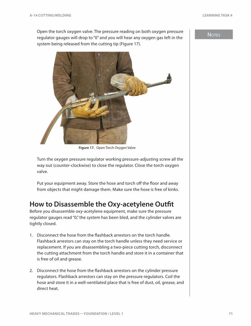
HEAVY MECHANICAL TRADES— FOUNDATION / LEVEL 1 71
NOTES
A-14 CUTTING/WELDING LEARNING TASK 4
Open the torch oxygen valve. The pressure reading on both oxygen pressure regulator gauges will drop to “0” and you will hear any oxygen gas left in the system being released from the cutting tip (Figure 17).
Figure 17. Open Torch Oxygen Valve
Turn the oxygen pressure regulator working pressure-adjusting screw all the way out (counter-clockwise) to close the regulator. Close the torch oxygen valve.
Put your equipment away. Store the hose and torch o� the �oor and away from objects that might damage them. Make sure the hose is free of kinks.
How to Disassemble the Oxy-acetylene Out�tBefore you disassemble oxy-acetylene equipment, make sure the pressure regulator gauges read “0,” the system has been bled, and the cylinder valves are tightly closed.
1. Disconnect the hose from the �ashback arrestors on the torch handle. Flashback arrestors can stay on the torch handle unless they need service or replacement. If you are disassembling a two-piece cutting torch, disconnect the cutting attachment from the torch handle and store it in a container that is free of oil and grease.
2. Disconnect the hose from the �ashback arrestors on the cylinder pressure regulators. Flashback arrestors can stay on the pressure regulators. Coil the hose and store it in a well-ventilated place that is free of dust, oil, grease, and direct heat.
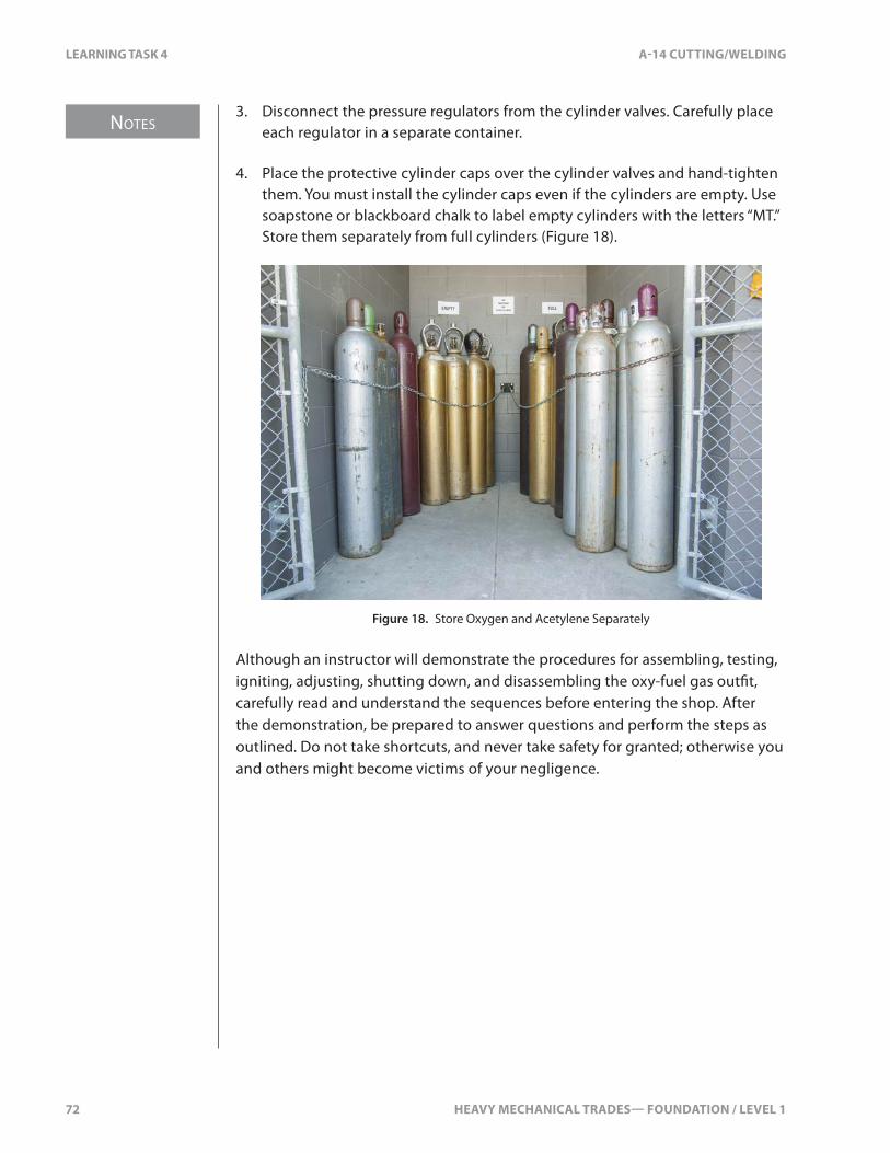
NOTES
72 HEAVY MECHANICAL TRADES— FOUNDATION / LEVEL 1
LEARNING TASK 4 A-14 CUTTING/WELDING
3. Disconnect the pressure regulators from the cylinder valves. Carefully place each regulator in a separate container.
4. Place the protective cylinder caps over the cylinder valves and hand-tighten them. You must install the cylinder caps even if the cylinders are empty. Use soapstone or blackboard chalk to label empty cylinders with the letters “MT.” Store them separately from full cylinders (Figure 18).
Figure 18. Store Oxygen and Acetylene Separately
Although an instructor will demonstrate the procedures for assembling, testing, igniting, adjusting, shutting down, and disassembling the oxy-fuel gas out�t, carefully read and understand the sequences before entering the shop. After the demonstration, be prepared to answer questions and perform the steps as outlined. Do not take shortcuts, and never take safety for granted; otherwise you and others might become victims of your negligence.
HEAVY MECHANICAL TRADES— FOUNDATION / LEVEL 1 73
A-14 CUTTING/WELDING SELF TEST 4
SELF TEST 4
1. What is the �rst step in putting out a �re in the hoses of an oxy-acetylene out�t?
a. use a �re extinguisher on the hoses
b. close only the acetylene cylinder valve
c. close only the oxygen cylinder valve
d. close both the oxygen and acetylene cylinder valves
2. What must you do before you attach the pressure regulators to the cylinders?
a. replace cylinder caps on the cylinder
b. install �ashback arrestors
c. crack the cylinder valves
d. seal the double-sealing valve
3. What �ame has too much acetylene?
a. oxidizing
b. acetylide
c. carburizing
d. neutral

74 HEAVY MECHANICAL TRADES— FOUNDATION / LEVEL 1

HEAVY MECHANICAL TRADES— FOUNDATION / LEVEL 1 75
NOTES
A-14 CUTTING/WELDING LEARNING TASK 5
LEARNING TASK 5
Cut Mild Steel with Oxy-acetylene Equipment
Set-upSettings of Preheat FlamesAdjustment of preheat �ames a�ects the quality of a cut. If the preheat �ames are too small, preheating is too slow. The cut will have the same problems that occur when the speed of travel is too slow. When preheat �ames are too long, the cut is too fast, with too much slag and an irregular top edge.
Position of Cutting Torch TipThe inner cone of the preheat �ame should be held 1.5–3 mm (1⁄6–1⁄8 in.) from the surface of the base metal. If the tip is allowed to touch the base metal, it could cause a back�re or the tip to overheat. Also, scale or slag from the surface of the base metal can get into the cutting ori�ce, which will result in a poor cut. The position of the preheat holes is another factor to consider. Cutting tips come with di�erent numbers of preheat holes, depending on the tip size and design. For a straight, square cut, the preheat holes should be positioned so that two preheat holes follow each other along the line of cut (Figure 1). Otherwise, preheating is slower, and the cut displays a characteristic rounded top edge and irregular kerf (width of the cut).
Figure 1. Cutting Tip Pre-heat Hole Alignment
When cutting a bevel, you must change the position of the preheat holes in the tip (Figure 1). Setting the preheat holes in this position gives better preheat to the metal.
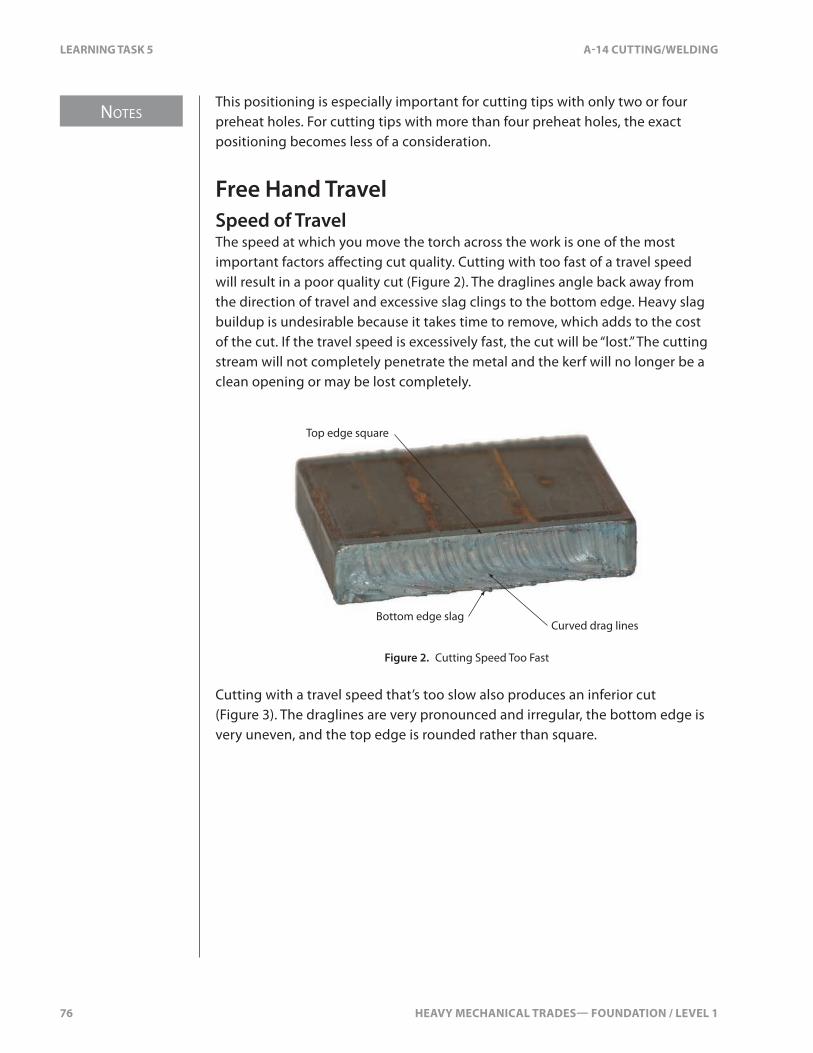
NOTES
76 HEAVY MECHANICAL TRADES— FOUNDATION / LEVEL 1
LEARNING TASK 5 A-14 CUTTING/WELDING
This positioning is especially important for cutting tips with only two or four preheat holes. For cutting tips with more than four preheat holes, the exact positioning becomes less of a consideration.
Free Hand TravelSpeed of TravelThe speed at which you move the torch across the work is one of the most important factors a�ecting cut quality. Cutting with too fast of a travel speed will result in a poor quality cut (Figure 2). The draglines angle back away from the direction of travel and excessive slag clings to the bottom edge. Heavy slag buildup is undesirable because it takes time to remove, which adds to the cost of the cut. If the travel speed is excessively fast, the cut will be “lost.” The cutting stream will not completely penetrate the metal and the kerf will no longer be a clean opening or may be lost completely.
Bottom edge slag
Top edge square
Curved drag lines
Figure 2. Cutting Speed Too Fast
Cutting with a travel speed that’s too slow also produces an inferior cut (Figure 3). The draglines are very pronounced and irregular, the bottom edge is very uneven, and the top edge is rounded rather than square.
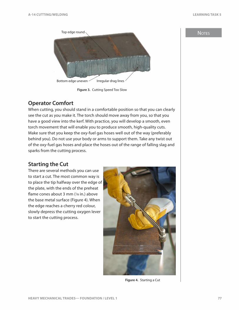
HEAVY MECHANICAL TRADES— FOUNDATION / LEVEL 1 77
NOTES
A-14 CUTTING/WELDING LEARNING TASK 5
Top edge round
Irregular drag linesBottom edge uneven
Figure 3. Cutting Speed Too Slow
Operator ComfortWhen cutting, you should stand in a comfortable position so that you can clearly see the cut as you make it. The torch should move away from you, so that you have a good view into the kerf. With practice, you will develop a smooth, even torch movement that will enable you to produce smooth, high-quality cuts. Make sure that you keep the oxy-fuel gas hoses well out of the way (preferably behind you). Do not use your body or arms to support them. Take any twist out of the oxy-fuel gas hoses and place the hoses out of the range of falling slag and sparks from the cutting process.
Starting the CutThere are several methods you can use to start a cut. The most common way is to place the tip halfway over the edge of the plate, with the ends of the preheat �ame cones about 3 mm (1⁄8 in.) above the base metal surface (Figure 4). When the edge reaches a cherry red colour, slowly depress the cutting oxygen lever to start the cutting process.
Figure 4. Starting a Cut

NOTES
78 HEAVY MECHANICAL TRADES— FOUNDATION / LEVEL 1
LEARNING TASK 5 A-14 CUTTING/WELDING
Factors A�ecting Cut QualityThe main factors a�ecting cut quality are:
• surface condition of the base metal• thickness of the base metal• cutting tip size• oxygen and fuel gas working pressures• setting of the preheat �ames• position of the cutting torch tip• not fully depressing the cutting oxygen lever• speed of travel• operator comfort and position
Surface ConditionBefore you cut a piece of steel, make sure the surfaces are clean. Any dirt, rust, grease, or slag will slow the cutting speed and result in a rough and irregular kerf.
Thickness of Base MetalThe base metal thickness has an important bearing on the quality of the cut. It’s the thickness that determines the correct cutting tip size, oxygen and fuel gas working pressures, speed of travel, and the angle at which you hold the torch.
When cutting steel plate, normally you hold the cutting tip perpendicular (90°) to the base metal (Figure 5A), especially when pro�le cutting. However, on material 13 mm (1⁄2 in.) and thinner, it is better to use a slight push angle (70–90° o� the base metal) when possible (Figure 5B). Using a push angle will preheat the base metal ahead of the cut as you work. Also, the slight angle allows the heat to de�ect o� the base metal and away from the tip. This helps to prevent the tip from overheating.
When cutting steel sheet, hold the cutting tip with an extreme push angle (10–20° o� the base metal). This low angle makes for faster, straighter, and cleaner cuts with less slag attaching itself to the base metal (Figure 5C).

HEAVY MECHANICAL TRADES— FOUNDATION / LEVEL 1 79
NOTES
A-14 CUTTING/WELDING LEARNING TASK 5
A B C
Figure 5. Angle of Cutting Torch Depends on Thickness of Metal
Cutting Tip SizeYou should always check the equipment manufacturer’s cutting chart for the cutting torch that you are using. The cutting chart will tell you the recommended tip size for the thickness of metal you are cutting, along with the correct working pressures.
Note that there is no standard tip size numbering system that equipment manufacturers follow. Each manufacturer develops and uses their own system. Also, gas consumption can vary from manufacturer to manufacturer. This means that tips from di�erent manufacturers might use di�erent volumes and pressures to cut the same thickness of metal. For safety and economic reasons, it’s important to check the equipment manufacturer’s cutting charts.
If you use a cutting tip that’s too large for the material being cut, you waste oxygen and end up with an unsatisfactory, bell-shaped kerf. If you use a cutting tip that’s too small for the material being cut, the cut proceeds much too slowly, causing the same e�ects as a slow cutting speed.
As well as selecting the correct size, you must make sure to keep your cutting tip clean and free of debris. Dirt, scale, or slag on the tip or in the cutting ori�ce will de�ect the stream of cutting oxygen and cause the cut to be of poor quality (Figure 6). There might be too much bottom-edge slag, a rough-cut surface and a concave cut surface.
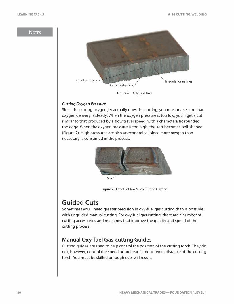
NOTES
80 HEAVY MECHANICAL TRADES— FOUNDATION / LEVEL 1
LEARNING TASK 5 A-14 CUTTING/WELDING
Rough cut faceBottom edge slag
Irregular drag lines
Figure 6. Dirty Tip Used
Cutting Oxygen PressureSince the cutting oxygen jet actually does the cutting, you must make sure that oxygen delivery is steady. When the oxygen pressure is too low, you’ll get a cut similar to that produced by a slow travel speed, with a characteristic rounded top edge. When the oxygen pressure is too high, the kerf becomes bell-shaped (Figure 7). High pressures are also uneconomical, since more oxygen than necessary is consumed in the process.
Slag
Figure 7. E�ects of Too Much Cutting Oxygen
Guided CutsSometimes you’ll need greater precision in oxy-fuel gas cutting than is possible with unguided manual cutting. For oxy-fuel gas cutting, there are a number of cutting accessories and machines that improve the quality and speed of the cutting process.
Manual Oxy-fuel Gas-cutting GuidesCutting guides are used to help control the position of the cutting torch. They do not, however, control the speed or preheat �ame-to-work distance of the cutting torch. You must be skilled or rough cuts will result.

HEAVY MECHANICAL TRADES— FOUNDATION / LEVEL 1 81
NOTES
A-14 CUTTING/WELDING LEARNING TASK 5
Straight Line Cutting GuideA piece of �at bar (or angle) can be used as a straight-line cutting guide (Figure 8). The cutting tip is held against the cutting guide to produce a straight cut.
Figure 8. Straight-line Cutting Guide
Circle Cutting GuideCircle cutting guides are used to cut circles and arcs. A typical circle-cutter attachment consists of an adjustable rod with a centre pivoting point, an adjustable wheel to set the pre-heat �ame-to-work distance, and a rotating mechanism for attaching to the cutting tip (Figure 9).
Figure 9. Typical Circle Cutting Guide
TemplatesTemplates serve as a master pattern for cutting irregular shapes. Once you have measured and cut one accurate pattern piece (allowing for the kerf ), you can then use that pattern piece as your template for all the identical pieces required. The use of templates saves time and ensures accuracy and consistency.

NOTES
82 HEAVY MECHANICAL TRADES— FOUNDATION / LEVEL 1
LEARNING TASK 5 A-14 CUTTING/WELDING
Hole PiercingSteps for piercing holes:
1. Preheat the marked area to a red colour, keeping the preheat �ames about 3 mm (1⁄8 in.) above the surface of the plate.
2. Lift the tip until the preheat �ames are about 13 mm (1⁄2 in.) above the plate and slowly depress the cutting control lever on the torch. You’ll see the metal start to burn and slag will blow away from the preheated area.
3. Lower the tip back to 3 mm (1⁄8 in.) above the plate and maintain a circular motion over the area of the hole until the cutting oxygen jet has passed through the steel.
4. When you’re �nished, there should be a clean hole with no slag on the cutting tip.

HEAVY MECHANICAL TRADES— FOUNDATION / LEVEL 1 83
A-14 CUTTING/WELDING SELF TEST 5
SELF TEST 5
1. What are the vertical lines called created by the cutting action on the metal?
a. bowlines
b. draglines
c. kerfs
d. stress ridges
2. How can a cut made too slowly be identi�ed?
a. curved draglines
b. too much slag
c. a rounded top edge
d. no bowlines

84 HEAVY MECHANICAL TRADES— FOUNDATION / LEVEL 1
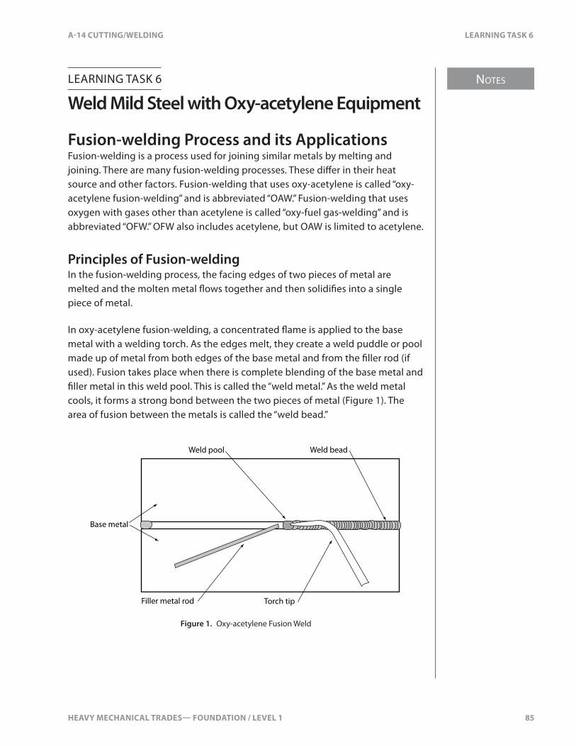
HEAVY MECHANICAL TRADES— FOUNDATION / LEVEL 1 85
NOTES
A-14 CUTTING/WELDING LEARNING TASK 6
LEARNING TASK 6
Weld Mild Steel with Oxy-acetylene Equipment
Fusion-welding Process and its ApplicationsFusion-welding is a process used for joining similar metals by melting and joining. There are many fusion-welding processes. These di�er in their heat source and other factors. Fusion-welding that uses oxy-acetylene is called “oxy-acetylene fusion-welding” and is abbreviated “OAW.” Fusion-welding that uses oxygen with gases other than acetylene is called “oxy-fuel gas-welding” and is abbreviated “OFW.” OFW also includes acetylene, but OAW is limited to acetylene.
Principles of Fusion-weldingIn the fusion-welding process, the facing edges of two pieces of metal are melted and the molten metal �ows together and then solidi�es into a single piece of metal.
In oxy-acetylene fusion-welding, a concentrated �ame is applied to the base metal with a welding torch. As the edges melt, they create a weld puddle or pool made up of metal from both edges of the base metal and from the �ller rod (if used). Fusion takes place when there is complete blending of the base metal and �ller metal in this weld pool. This is called the “weld metal.” As the weld metal cools, it forms a strong bond between the two pieces of metal (Figure 1). The area of fusion between the metals is called the “weld bead.”
Weld pool
Base metal
Filler metal rod
Weld bead
Torch tip
Figure 1. Oxy-acetylene Fusion Weld
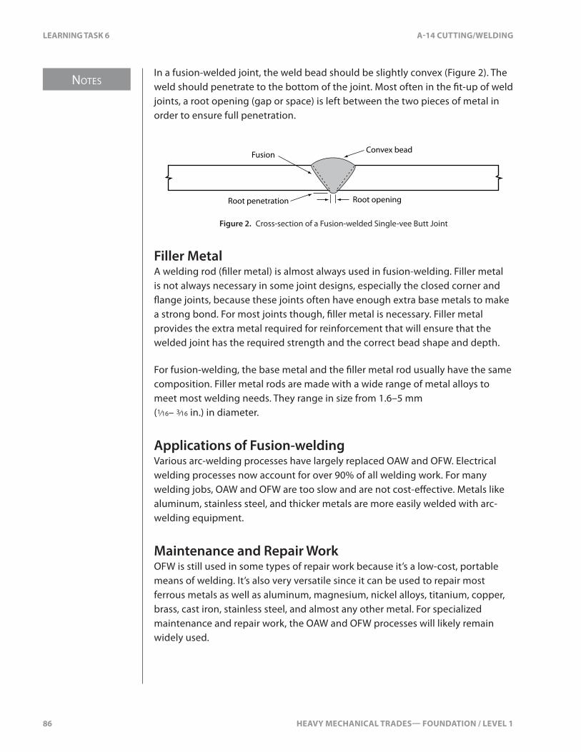
NOTES
86 HEAVY MECHANICAL TRADES— FOUNDATION / LEVEL 1
LEARNING TASK 6 A-14 CUTTING/WELDING
In a fusion-welded joint, the weld bead should be slightly convex (Figure 2). The weld should penetrate to the bottom of the joint. Most often in the �t-up of weld joints, a root opening (gap or space) is left between the two pieces of metal in order to ensure full penetration.
Root penetration Root opening
Fusion Convex bead
Figure 2. Cross-section of a Fusion-welded Single-vee Butt Joint
Filler MetalA welding rod (�ller metal) is almost always used in fusion-welding. Filler metal is not always necessary in some joint designs, especially the closed corner and �ange joints, because these joints often have enough extra base metals to make a strong bond. For most joints though, �ller metal is necessary. Filler metal provides the extra metal required for reinforcement that will ensure that the welded joint has the required strength and the correct bead shape and depth.
For fusion-welding, the base metal and the �ller metal rod usually have the same composition. Filler metal rods are made with a wide range of metal alloys to meet most welding needs. They range in size from 1.6–5 mm (1⁄16– 3⁄16 in.) in diameter.
Applications of Fusion-weldingVarious arc-welding processes have largely replaced OAW and OFW. Electrical welding processes now account for over 90% of all welding work. For many welding jobs, OAW and OFW are too slow and are not cost-e�ective. Metals like aluminum, stainless steel, and thicker metals are more easily welded with arc-welding equipment.
Maintenance and Repair WorkOFW is still used in some types of repair work because it’s a low-cost, portable means of welding. It’s also very versatile since it can be used to repair most ferrous metals as well as aluminum, magnesium, nickel alloys, titanium, copper, brass, cast iron, stainless steel, and almost any other metal. For specialized maintenance and repair work, the OAW and OFW processes will likely remain widely used.
HEAVY MECHANICAL TRADES— FOUNDATION / LEVEL 1 87
NOTES
A-14 CUTTING/WELDING LEARNING TASK 6
Fluxes for Fusion-weldingFlux is a chemical compound that’s applied to weld joint surfaces before welding or brazing to help the bonding process. A �ux is required for all braze-welding and brazing procedures. Fusion-welding of cast iron, stainless steel, and some non-ferrous metals also requires a �ux. Flux is not usually needed for fusion-welding low-carbon steel. The high temperature required produces enough heat to melt any iron oxides already present or that have formed during the welding process. These oxides �oat to the surface of the weld pool and do not interfere with the fusion process.
When fusion-welding cast iron, stainless steel, aluminum, or magnesium, you’ll need a �ux. The oxides of these metals have a higher melting temperature than the parent metal. This is the same phenomenon that makes the metals di�cult to cut with an oxy-fuel gas-cutting torch. The oxides remain solid at the temperature that melts the parent metal and interfere with the fusion process. The �ux serves to increases the �uidity of the molten metal, dissolve oxides, and �oat o� impurities to the surface of the weld pool.
The �ux you choose depends on the metal being welded, there’s no one universal �ux. When choosing a �ux for fusion-welding, be sure to read the manufacturer’s label carefully to see if the �ux is suitable for the metal you’re welding.
Purpose of FluxFlux is always necessary for braze-welding and brazing processes to create a good bond. Flux serves three purposes:
• It chemically cleans the surface of the base metal, removing oxides that might not have been removed during pre-cleaning. Since braze-welding and brazing bonds require surface adhesion, it’s extremely important that the base metal surface be clean and free of oxides.
• It prevents the formation of oxides during the braze-welding and brazing processes. The heating of the base metal accelerates the formation of oxides. The �ux coats the weld joint and acts as a protective coating over the base metal.
• It allows the �ller metal to �ow easily on the base metal.
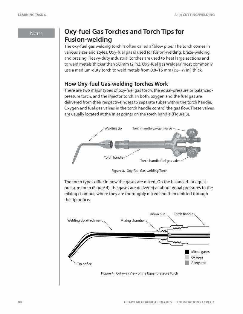
NOTES
88 HEAVY MECHANICAL TRADES— FOUNDATION / LEVEL 1
LEARNING TASK 6 A-14 CUTTING/WELDING
Oxy-fuel Gas Torches and Torch Tips for Fusion-weldingThe oxy-fuel gas welding torch is often called a “blow pipe.” The torch comes in various sizes and styles. Oxy-fuel gas is used for fusion-welding, braze-welding, and brazing. Heavy-duty industrial torches are used to heat large sections and to weld metals thicker than 50 mm (2 in.). Oxy-fuel gas Welders’ most commonly use a medium-duty torch to weld metals from 0.8–16 mm (1⁄32– 5⁄8 in.) thick.
How Oxy-fuel Gas-welding Torches WorkThere are two major types of oxy-fuel gas torch: the equal-pressure or balanced-pressure torch, and the injector torch. In both, oxygen and the fuel gas are delivered from their respective hoses to separate tubes within the torch handle. Oxygen and fuel gas valves in the torch handle control the gas �ow. These valves are usually located at the inlet points on the torch handle (Figure 3).
Torch handle fuel gas valveTorch handle
Torch handle oxygen valveWelding tip
Figure 3. Oxy-fuel Gas-welding Torch
The torch types di�er in how the gases are mixed. On the balanced- or equal-pressure torch (Figure 4), the gases are delivered at about equal pressures to the mixing chamber, where they are thoroughly mixed and then emitted through the tip ori�ce.
Tip orifice
Torch handle
Mixing chamber
Union nut
Welding tip attachment
Acetylene
Mixed gases
Oxygen
Figure 4. Cutaway View of the Equal-pressure Torch

HEAVY MECHANICAL TRADES— FOUNDATION / LEVEL 1 89
NOTES
A-14 CUTTING/WELDING LEARNING TASK 6
In injector-type torches, the oxygen gas �ows at a higher pressure than the fuel gas (Figure 5). The oxygen �ows through a venturi into the mixing chamber. As the oxygen passes through the venturi, the venturi e�ect allows the higher oxygen pressure to draw in the fuel gas through small openings so that the fuel gas is injected into the oxygen stream.
High-pressure oxygen
Low-pressure fuel gas
Injector
Mixing chamber
Figure 5. Cutaway View of the Injection Type Torch
The injector torch is used mainly with fuel gases that have very low delivery pressures. One drawback to the injector torch is the need for di�erent mixers for di�erent fuel gases. Before using an injector torch, you must check the torch carefully to make sure that the correct mixer attachment is installed.
Equal-pressure torches are much more versatile. You only need to select the correct tip for the fuel gas, since the mixing chamber is always correct.
Oxy-fuel Gas-welding TipsModern welding torches have separate, detachable welding tips that attach into the end of the torch handle. These tips are made of copper alloy, which is easily bent or dented, and they must be handled carefully and stored away from oil, grease, and paint.
Choosing the Correct Oxy-fuel Gas-welding TipThe correct choice of welding tip size depends mainly on three factors:
• type of metal• thickness of the metal• type of welding process
The weld tip size is measured by the diameter of the tip’s �ame ori�ce. A large tip has a large �ame ori�ce and is able to deliver greater volumes of heat.
Note that all welding tips, regardless of size, produce the same �ame temperature at the tip. The di�erence is in the volume of heat delivered.

NOTES
90 HEAVY MECHANICAL TRADES— FOUNDATION / LEVEL 1
LEARNING TASK 6 A-14 CUTTING/WELDING
The numbering system for oxy-fuel gas-welding tip sizes is similar to that of oxy-fuel gas-cutting tips. The system is not standardized, so you should follow the manufacturer’s recommendations.
Figure 6 shows how metal thickness determines the welding tip size used, and how tip size a�ects working-pressure settings on an oxy-fuel gas-welding torch. These listings vary with the type of welding tip, the type of torch, and the manufacturer.
Welding Pressures
Metal Thickness Tip Size Number Oxygen Acetylene
0.8 mm (1⁄32 in.) 0–17–14 kPa (1–2 psi)
7–14 kPa (1–2) psi
1.6 mm (1⁄16 in.) 1–214–21 kPa (2–3 psi)
14–21 kPa (2–3) psi
2.4 mm (3⁄32 in.) 1–314–28 kPa (2–4 psi)
14–28 kPa (2–4) psi
3.2 mm (1⁄8 in.) 3–421–34 kPa (3–5 psi)
21–34 kPa (3–5) psi
4.8 mm (3⁄16 in.) 4–528–41 kPa (4–6 psi)
28–41 kPa (4–6) psi
6.4 mm (1⁄4 in.) 5–634–41 kPa (5–6 psi)
34–41 kPa (5–6) psi
9.5 mm (3⁄8 in.) 6–841–55 kPa (6–8 psi)
41–55 kPa (6–8) psi
Figure 6. Typical OAW Tip Chart for Steel Plate
Figure 7. Tip Size Stamped in Tip

HEAVY MECHANICAL TRADES— FOUNDATION / LEVEL 1 91
NOTES
A-14 CUTTING/WELDING LEARNING TASK 6
The type of welding process also a�ects the size of the welding tip you will require. Braze-welding and brazing requires less heat than fusion-welding, and usually a smaller tip size is used for metals of comparable thicknesses.
The type of material also a�ects your choice of the welding tip size. When you are welding aluminum, copper, and other non-ferrous metals, the heat dissipates so quickly that you will need a larger tip size than you would for welding steel of the same thickness.
It’s important that you use the correct tip size. If you use a tip that is too large, the metal will heat very quickly and it can burn through. This can be disastrous during low-temperature braze-welding or brazing, where you don’t want the base metal melting at all.
If you fusion-weld using a tip that’s too small, it will take a long time for the base metal to melt. In braze-welding and brazing; a tip that’s too small will cause the base metal to take too long to get to the correct temperature to melt the �ller rod. If it’s taking too long to reach the desired temperature, do not increase the gas pressure. Change to a larger size tip instead. Trying to increase the gas pressure will generally produce a very noisy, turbulent �ame that disturbs the weld pool and creates poor welds.
Choosing the correct welding tip for all circumstances requires experience. Always check the manufacturer’s welding tip speci�cation chart for the correct tip size for the thickness of base metal you’re welding.
It’s important to connect only welding tips and attachments that are speci�cally designed to mate with the torch handle. After choosing the correct tip size, insert the tip attachment into the torch handle. Examine the threads, seals, and seats before attaching the tip to the torch. If there’s a damaged seal or seat, the resulting leak can cause a �re or explosion.
Tighten the union nut by hand only. Never use a wrench.
Welding Tip MaintenanceThe welding tip will need to be cleaned from time to time. It can become clogged with small particles from the welding process and this can greatly a�ect the performance of the torch.
The cleaning process is similar to cleaning an oxy-fuel gas-cutting tip. Use a �at-tip �le to smooth o� and remove any carbon or metal particles from the end of the tip (Figure 8).
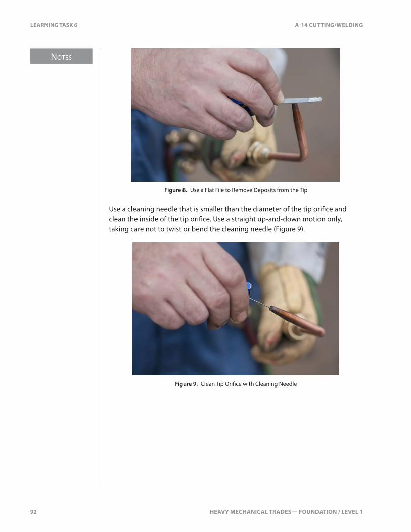
NOTES
92 HEAVY MECHANICAL TRADES— FOUNDATION / LEVEL 1
LEARNING TASK 6 A-14 CUTTING/WELDING
Figure 8. Use a Flat File to Remove Deposits from the Tip
Use a cleaning needle that is smaller than the diameter of the tip ori�ce and clean the inside of the tip ori�ce. Use a straight up-and-down motion only, taking care not to twist or bend the cleaning needle (Figure 9).
Figure 9. Clean Tip Ori�ce with Cleaning Needle
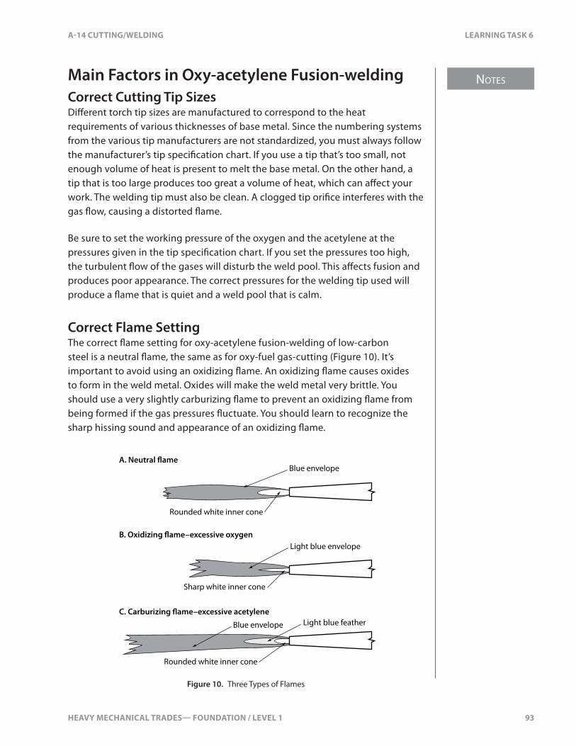
HEAVY MECHANICAL TRADES— FOUNDATION / LEVEL 1 93
NOTES
A-14 CUTTING/WELDING LEARNING TASK 6
Main Factors in Oxy-acetylene Fusion-weldingCorrect Cutting Tip SizesDi�erent torch tip sizes are manufactured to correspond to the heat requirements of various thicknesses of base metal. Since the numbering systems from the various tip manufacturers are not standardized, you must always follow the manufacturer’s tip speci�cation chart. If you use a tip that’s too small, not enough volume of heat is present to melt the base metal. On the other hand, a tip that is too large produces too great a volume of heat, which can a�ect your work. The welding tip must also be clean. A clogged tip ori�ce interferes with the gas �ow, causing a distorted �ame.
Be sure to set the working pressure of the oxygen and the acetylene at the pressures given in the tip speci�cation chart. If you set the pressures too high, the turbulent �ow of the gases will disturb the weld pool. This a�ects fusion and produces poor appearance. The correct pressures for the welding tip used will produce a �ame that is quiet and a weld pool that is calm.
Correct Flame SettingThe correct �ame setting for oxy-acetylene fusion-welding of low-carbon steel is a neutral �ame, the same as for oxy-fuel gas-cutting (Figure 10). It’s important to avoid using an oxidizing �ame. An oxidizing �ame causes oxides to form in the weld metal. Oxides will make the weld metal very brittle. You should use a very slightly carburizing �ame to prevent an oxidizing �ame from being formed if the gas pressures �uctuate. You should learn to recognize the sharp hissing sound and appearance of an oxidizing �ame.
A. Neutral �ame
B. Oxidizing �ame–excessive oxygen
C. Carburizing �ame–excessive acetylene
Blue envelope
Rounded white inner cone
Light blue featherBlue envelope
Light blue envelope
Sharp white inner cone
Rounded white inner cone
Figure 10. Three Types of Flames

NOTES
94 HEAVY MECHANICAL TRADES— FOUNDATION / LEVEL 1
LEARNING TASK 6 A-14 CUTTING/WELDING
Flame to Work DistanceThe tip of the inner cone of the �ame should be about 1.6–3.2 mm (1⁄16–1⁄8 in.) above the base metal (Figure 11). This is the hottest part of the oxy-acetylene �ame. You want the metal to reach its molten state as quickly as possible and to maintain the weld pool during the welding process.
Direction of travel
1.6–3.2 mm
30–45º
Figure 11. Optimal Flame-to-work Distance
Types of Welding TechniquesThere are two basic techniques used in oxy-acetylene welding: forehand welding and backhand welding.
In the forehand technique, the direction of travel is the direction the tip is pointing (Figure 12). In e�ect, the torch is “pushing” the weld pool and the welding �ame is preheating the weld joint just ahead of the torch. The �ller- metal rod is held in front of the weld pool and is fed in as required. In the backhand technique, the torch tip is tilted so that it points away from the direction of travel (Figure 12). In e�ect, the torch is “dragging” the weld pool and the tip points back toward the weld pool. The �ller-metal rod is held in front of the weld pool and follows the movement of the torch.
Forehand Backhand
Direction of travel
30–45º30–45º
Direction of travel
45–75º
90º–120º 45º–90º
Figure 12. Welding Techniques
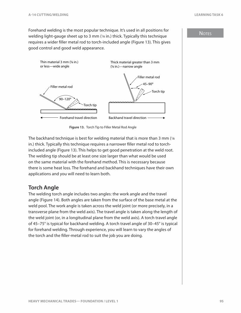
HEAVY MECHANICAL TRADES— FOUNDATION / LEVEL 1 95
NOTES
A-14 CUTTING/WELDING LEARNING TASK 6
Forehand welding is the most popular technique. It’s used in all positions for welding light-gauge sheet up to 3 mm (1⁄8 in.) thick. Typically this technique requires a wider �ller metal rod to torch-included angle (Figure 13). This gives good control and good weld appearance.
Thick material greater than 3 mm (1⁄8 in.)—narrow angle
Thin material 3 mm (1⁄8 in.) or less—wide angle
90–120º
45–90º
Forehand travel direction Backhand travel direction
Torch tip
Torch tip
Filler metal rod
Filler metal rod
Figure 13. Torch Tip to Filler Metal Rod Angle
The backhand technique is best for welding material that is more than 3 mm (1⁄8 in.) thick. Typically this technique requires a narrower �ller metal rod to torch-included angle (Figure 13). This helps to get good penetration at the weld root. The welding tip should be at least one size larger than what would be used on the same material with the forehand method. This is necessary because there is some heat loss. The forehand and backhand techniques have their own applications and you will need to learn both.
Torch AngleThe welding torch angle includes two angles: the work angle and the travel angle (Figure 14). Both angles are taken from the surface of the base metal at the weld pool. The work angle is taken across the weld joint (or more precisely, in a transverse plane from the weld axis). The travel angle is taken along the length of the weld joint (or, in a longitudinal plane from the weld axis). A torch travel angle of 45–75° is typical for backhand welding. A torch travel angle of 30–45° is typical for forehand welding. Through experience, you will learn to vary the angles of the torch and the �ller-metal rod to suit the job you are doing.

NOTES
96 HEAVY MECHANICAL TRADES— FOUNDATION / LEVEL 1
LEARNING TASK 6 A-14 CUTTING/WELDING
45–75º 90º
90º
30º
Backhand travel direction
Forehand travel direction
Work angleTravel angle
Front view End view
Front view End view
Figure 14. Torch Tip Angle and Work Angle
Speed of TravelSpeed of travel (rate of travel) is a very important factor in producing good fusion welds. The speed of travel depends on the base metal thickness, the welding joint design, and the volume of heat produced by the welding torch.
If your speed of travel is too fast, the weld bead becomes too narrow and the bead ripples become pointed. The heat has not penetrated and lack of fusion is the result (Figure 15).
Figure 15. Weld Bead Formed When Speed of Travel Was Too Fast
If your speed of travel is too slow, it will result in too much penetration and a scaly appearance on the weld bead (Figure 16).

HEAVY MECHANICAL TRADES— FOUNDATION / LEVEL 1 97
NOTES
A-14 CUTTING/WELDING LEARNING TASK 6
Figure 16. Weld Bead Formed When Speed of Travel Was Too Slow
If you allow too much heat to build up, the molten weld pool will collapse through to the bottom of the plate and leave holes (Figure 17). The underside of the weld might have molten metal that has solidi�ed, forming icicle-like structures.
Figure 17. Weld Bead Formed with Too Much Heat
If you complete your weld properly, it will have uniform bead ripples, even bead width and a shiny surface appearance (Figure 18).
Figure 18. Weld Bead Formed Correctly
The movement of the torch is also extremely important. As soon as there is a small weld pool (pool of molten weld metal), start to move the torch forward with a side-to-side or circular motion. At the same time, insert the end of the �ller rod into the weld pool, dipping the rod into and out of the weld pool. The �ller rod should be withdrawn just enough to remove it from the weld pool, but not entirely from the �ame, since it should not be allowed to oxidize or cool.

NOTES
98 HEAVY MECHANICAL TRADES— FOUNDATION / LEVEL 1
LEARNING TASK 6 A-14 CUTTING/WELDING
Coordinating the motion of the �ller rod and the motion of the welding torch is an important factor in producing a quality weld. You will become better at this with continued practice.
Welder Comfort and PositionWhen welding, you should always position yourself so you can clearly see the weld pool, and you should (whenever possible) be in a �rm, steady position. Bracing your body against something stationary can help. Place the elbow of your �ller-rod arm on something solid or rest your hip against the edge of your workbench to improve your ability to hold steady. Using both your elbow and your hip is best. Do not brace your torch hand. If you weld standing upright with no part of your body touching a steady point, you’ll �nd that you will have di�culty steadying yourself.
Find a way to hold the torch comfortably so that you have good control over the movement of the tip. Support or arrange the gas hoses so there is no interference with torch movement. The important thing is to be comfortable and have good control over the torch. If you’re right-handed, welding with the forehand technique, the direction of travel is normally from right to left. If you’re left-handed, the direction of travel would normally be from left to right.
Weld Faults in the Oxy-acetylene Welding ProcessThere are several common weld defects you should be aware of and learn to avoid. The faults presented here are the ones you’re most likely to experience when oxy-acetylene welding. These defects are called “structural discontinuities.” They include:
• incomplete penetration• incomplete fusion• undercut
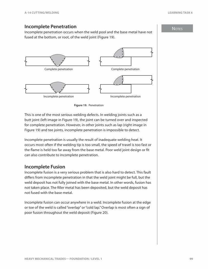
HEAVY MECHANICAL TRADES— FOUNDATION / LEVEL 1 99
NOTES
A-14 CUTTING/WELDING LEARNING TASK 6
Incomplete PenetrationIncomplete penetration occurs when the weld pool and the base metal have not fused at the bottom, or root, of the weld joint (Figure 19).
Complete penetration
Incomplete penetration
Complete penetration
Incomplete penetration
A BFigure 19. Penetration
This is one of the most serious welding defects. In welding joints such as a butt joint (left image in Figure 19), the joint can be turned over and inspected for complete penetration. However, in other joints such as lap (right image in Figure 19) and tee joints, incomplete penetration is impossible to detect.
Incomplete penetration is usually the result of inadequate welding heat. It occurs most often if the welding tip is too small, the speed of travel is too fast or the �ame is held too far away from the base metal. Poor weld joint design or �t can also contribute to incomplete penetration.
Incomplete FusionIncomplete fusion is a very serious problem that is also hard to detect. This fault di�ers from incomplete penetration in that the weld joint might be full, but the weld deposit has not fully joined with the base metal. In other words, fusion has not taken place. The �ller metal has been deposited, but the weld deposit has not fused with the base metal.
Incomplete fusion can occur anywhere in a weld. Incomplete fusion at the edge or toe of the weld is called “overlap” or “cold lap.” Overlap is most often a sign of poor fusion throughout the weld deposit (Figure 20).
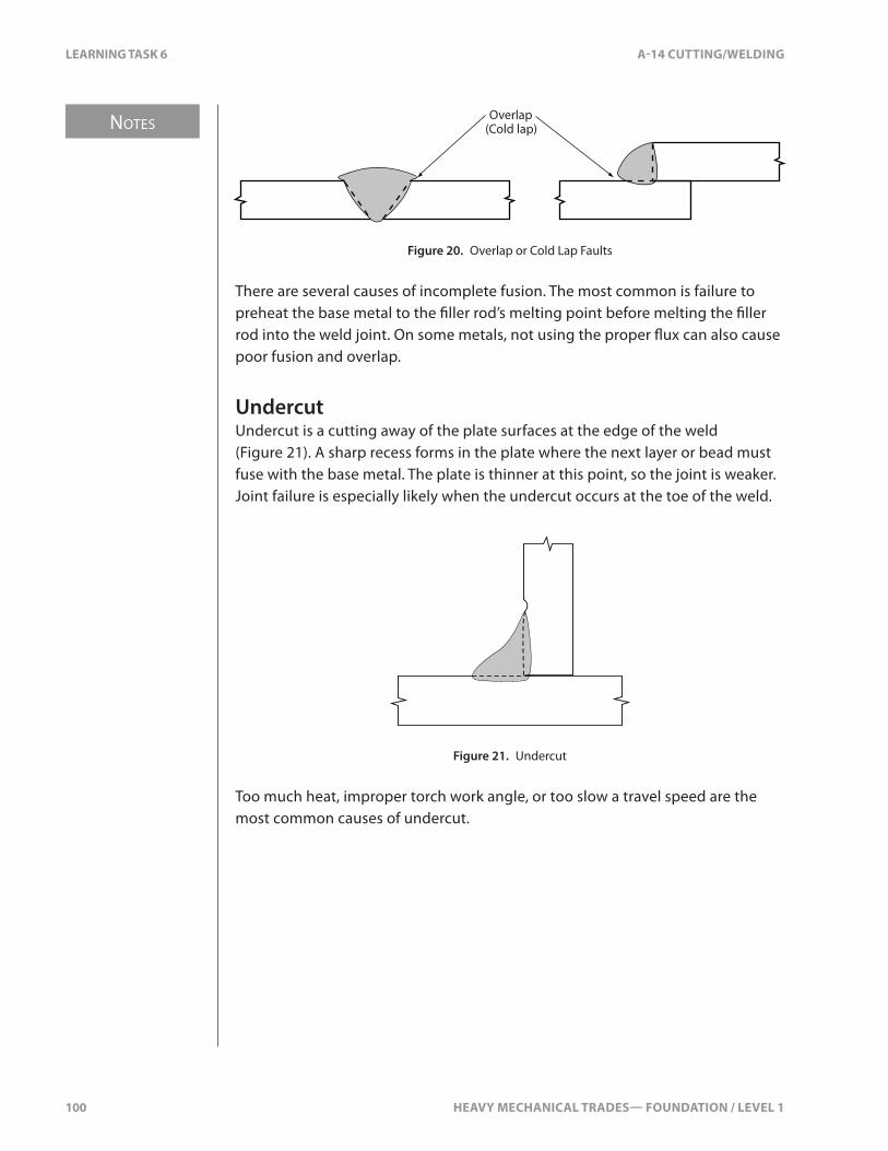
NOTES
100 HEAVY MECHANICAL TRADES— FOUNDATION / LEVEL 1
LEARNING TASK 6 A-14 CUTTING/WELDING
Overlap(Cold lap)
Figure 20. Overlap or Cold Lap Faults
There are several causes of incomplete fusion. The most common is failure to preheat the base metal to the �ller rod’s melting point before melting the �ller rod into the weld joint. On some metals, not using the proper �ux can also cause poor fusion and overlap.
UndercutUndercut is a cutting away of the plate surfaces at the edge of the weld (Figure 21). A sharp recess forms in the plate where the next layer or bead must fuse with the base metal. The plate is thinner at this point, so the joint is weaker. Joint failure is especially likely when the undercut occurs at the toe of the weld.
Figure 21. Undercut
Too much heat, improper torch work angle, or too slow a travel speed are the most common causes of undercut.

HEAVY MECHANICAL TRADES— FOUNDATION / LEVEL 1 101
NOTES
A-14 CUTTING/WELDING LEARNING TASK 6
Reinforcement on Grooved WeldsIn addition to these serious structural faults, there are weld faults that a�ect the dimension of the �nished weld. If the dimension of the �nished weld does not meet speci�cation, it’s called a “dimensional defect.”
Metal deposited above the surface of the plate is called “reinforcement.” In a groove weld, there should be su�cient weld deposit to build up the weld pro�le above the surface of the base metal (Figure 22). This reinforcement, however, should not be higher than 3.2 mm (1⁄8 in.).
Adequate reinforcement
Insu�cient reinforcement
Figure 22. Reinforcement
Correct Weld Pro�leFillet welds are used on lap, tee, and corner joints (Figure 23). A �llet weld is roughly triangular in shape. The most preferred �llet weld is �at to slightly convex in order to provide the necessary strength to the welded joint. Concave weld pro�les can be speci�ed for certain welds, but generally, they should be avoided.
Size
Flat
45º
Size
Concave
Size
Size
Convex
C
Figure 23. Fillet Weld Pro�les
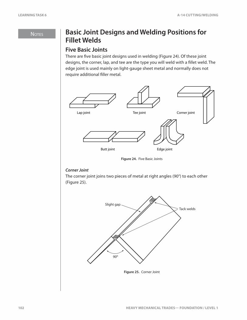
NOTES
102 HEAVY MECHANICAL TRADES— FOUNDATION / LEVEL 1
LEARNING TASK 6 A-14 CUTTING/WELDING
Basic Joint Designs and Welding Positions for Fillet WeldsFive Basic JointsThere are �ve basic joint designs used in welding (Figure 24). Of these joint designs, the corner, lap, and tee are the type you will weld with a �llet weld. The edge joint is used mainly on light-gauge sheet metal and normally does not require additional �ller metal.
Lap joint
Butt joint Edge joint
Tee joint Corner joint
Figure 24. Five Basic Joints
Corner JointThe corner joint joins two pieces of metal at right angles (90°) to each other (Figure 25).
Tack weldsSlight gap
90º
Figure 25. Corner Joint

HEAVY MECHANICAL TRADES— FOUNDATION / LEVEL 1 103
NOTES
A-14 CUTTING/WELDING LEARNING TASK 6
When forming a corner joint, position the two pieces to form an angle close to 90°. Make sure that the edges of the weld joint meet from end to end and do not overlap.
Incomplete penetration is a relatively common defect in corner joints. It can result from a �t that’s too tight. Therefore, it’s necessary to leave a slight gap between the plates in order to ensure complete penetration. Incomplete penetration can also be caused by a speed of travel that’s too fast. In this case, the weld pool becomes too small to melt through to the bottom edges of the plates. A welding �ame that does not supply enough volume of heat to penetrate to the bottom edges of the plates can also cause incomplete penetration.
Lap JointA lap joint is used to join two pieces of metal that overlap (Figure 26). It’s a useful way of joining two plates where a “tight” joint is necessary, but great strength isn’t required. This joint is not practical for many applications. Some base metal is wasted in the overlap, the plates are o�set (which might not be desirable) and the joint itself is not as strong as a butt joint.
Tack welds19 mm (¾")
t Tack welds
Figure 26. Lap Joint
A good lap joint weld is slightly convex in shape (Figure 27A). If not enough �ller metal is added, a concave pro�le will result (Figure 27B).
A. Good weld bead contour B. Bad weld bead contour
Figure 27. Cross-section of Lap Joint Bead Contours
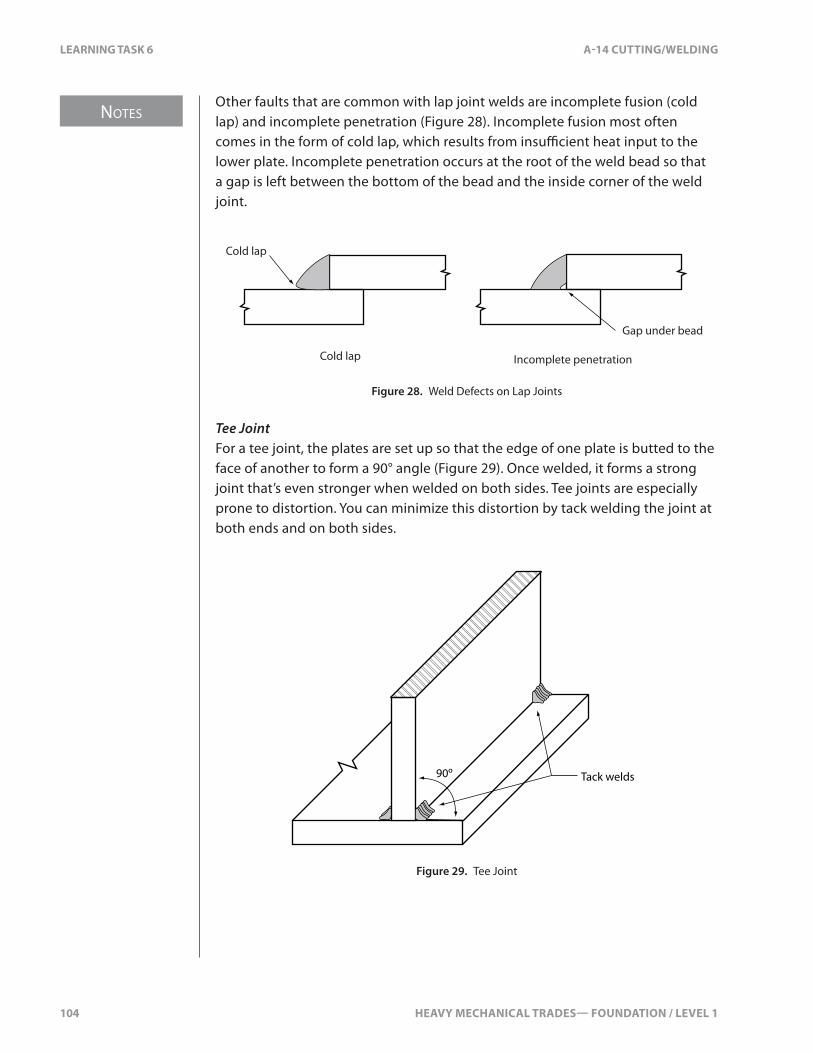
NOTES
104 HEAVY MECHANICAL TRADES— FOUNDATION / LEVEL 1
LEARNING TASK 6 A-14 CUTTING/WELDING
Other faults that are common with lap joint welds are incomplete fusion (cold lap) and incomplete penetration (Figure 28). Incomplete fusion most often comes in the form of cold lap, which results from insu�cient heat input to the lower plate. Incomplete penetration occurs at the root of the weld bead so that a gap is left between the bottom of the bead and the inside corner of the weld joint.
Cold lap
Gap under bead
Cold lap Incomplete penetration
Figure 28. Weld Defects on Lap Joints
Tee JointFor a tee joint, the plates are set up so that the edge of one plate is butted to the face of another to form a 90° angle (Figure 29). Once welded, it forms a strong joint that’s even stronger when welded on both sides. Tee joints are especially prone to distortion. You can minimize this distortion by tack welding the joint at both ends and on both sides.
Tack welds90º
Figure 29. Tee Joint

HEAVY MECHANICAL TRADES— FOUNDATION / LEVEL 1 105
NOTES
A-14 CUTTING/WELDING LEARNING TASK 6
A cross-section of the weld pro�le should show the bead to be �at or slightly convex, with penetration through to the inside corner of the weld joint (Figure 30). The legs of the tee joint weld bead should be equal in length, which means the completed weld should be evenly distributed between the vertical and horizontal members of the joint.
Figure 30. Tee Joint Weld Bead Contour
A fault that’s common to tee joints is undercut on the vertical plate (Figure 31A). Using an extreme weaving motion of the torch usually causes this. Another common problem is a weak, concave weld bead (Figure 31B), which occurs when not enough �ller metal is added to the weld pool.
Undercut
Concave
A B
Figure 31. Common Faults on Tee Joints
The tee joint is a di�cult weld to master. When you have become pro�cient, the weld bead will be �at or slightly convex and have good fusion, consistent width, a clean appearance, equal legs, and no undercut.
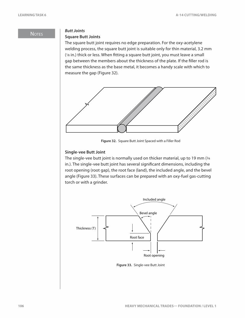
NOTES
106 HEAVY MECHANICAL TRADES— FOUNDATION / LEVEL 1
LEARNING TASK 6 A-14 CUTTING/WELDING
Butt JointsSquare Butt JointsThe square butt joint requires no edge preparation. For the oxy-acetylene welding process, the square butt joint is suitable only for thin material, 3.2 mm (1⁄8 in.) thick or less. When �tting a square butt joint, you must leave a small gap between the members about the thickness of the plate. If the �ller rod is the same thickness as the base metal, it becomes a handy scale with which to measure the gap (Figure 32).
Figure 32. Square Butt Joint Spaced with a Filler Rod
Single-vee Butt JointThe single-vee butt joint is normally used on thicker material, up to 19 mm (3⁄4 in.). The single-vee butt joint has several signi�cant dimensions, including the root opening (root gap), the root face (land), the included angle, and the bevel angle (Figure 33). These surfaces can be prepared with an oxy-fuel gas-cutting torch or with a grinder.
Root opening
Root face
Included angle
Bevel angle
Thickness (T)
Figure 33. Single-vee Butt Joint
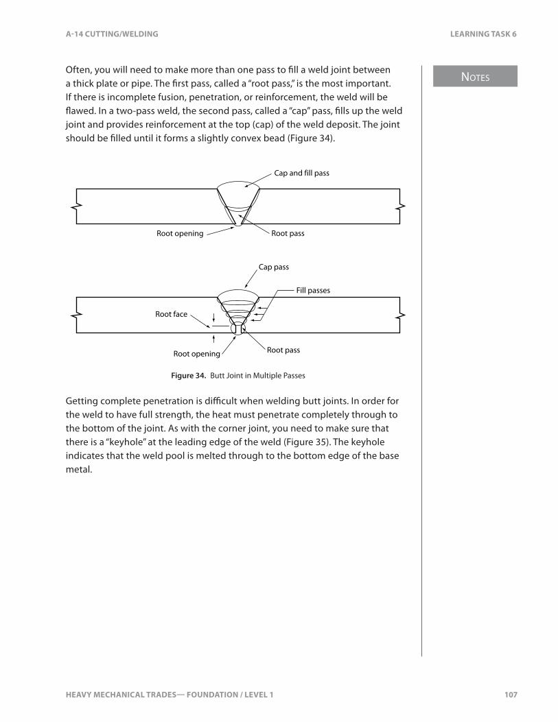
HEAVY MECHANICAL TRADES— FOUNDATION / LEVEL 1 107
NOTES
A-14 CUTTING/WELDING LEARNING TASK 6
Often, you will need to make more than one pass to �ll a weld joint between a thick plate or pipe. The �rst pass, called a “root pass,” is the most important. If there is incomplete fusion, penetration, or reinforcement, the weld will be �awed. In a two-pass weld, the second pass, called a “cap” pass, �lls up the weld joint and provides reinforcement at the top (cap) of the weld deposit. The joint should be �lled until it forms a slightly convex bead (Figure 34).
Cap and fill pass
Root passRoot opening
Cap pass
Fill passes
Root pass
Root face
Root opening
Figure 34. Butt Joint in Multiple Passes
Getting complete penetration is di�cult when welding butt joints. In order for the weld to have full strength, the heat must penetrate completely through to the bottom of the joint. As with the corner joint, you need to make sure that there is a “keyhole” at the leading edge of the weld (Figure 35). The keyhole indicates that the weld pool is melted through to the bottom edge of the base metal.
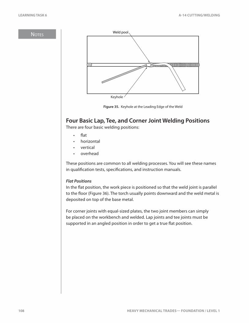
NOTES
108 HEAVY MECHANICAL TRADES— FOUNDATION / LEVEL 1
LEARNING TASK 6 A-14 CUTTING/WELDING
Weld pool
Keyhole
Figure 35. Keyhole at the Leading Edge of the Weld
Four Basic Lap, Tee, and Corner Joint Welding PositionsThere are four basic welding positions:
• �at• horizontal• vertical• overhead
These positions are common to all welding processes. You will see these names in quali�cation tests, speci�cations, and instruction manuals.
Flat PositionsIn the �at position, the work piece is positioned so that the weld joint is parallel to the �oor (Figure 36). The torch usually points downward and the weld metal is deposited on top of the base metal.
For corner joints with equal-sized plates, the two joint members can simply be placed on the workbench and welded. Lap joints and tee joints must be supported in an angled position in order to get a true �at position.

HEAVY MECHANICAL TRADES— FOUNDATION / LEVEL 1 109
NOTES
A-14 CUTTING/WELDING LEARNING TASK 6
Figure 36. Flat Positions
Horizontal PositionIn the horizontal position, the work piece is also positioned so that the weld joint is parallel to the �oor so the surfaces of the plates are vertical (Figure 37). For butt joints, the two plates are supported in the vertical position. The other four joints are positioned so that one edge surface of the weld joint is parallel to the �oor and the weld is on top of the plate. With horizontal welds, the main di�culty is that gravity causes the weld pool to �ow toward the lower side of the weld joint.
Figure 37. Horizontal Positions
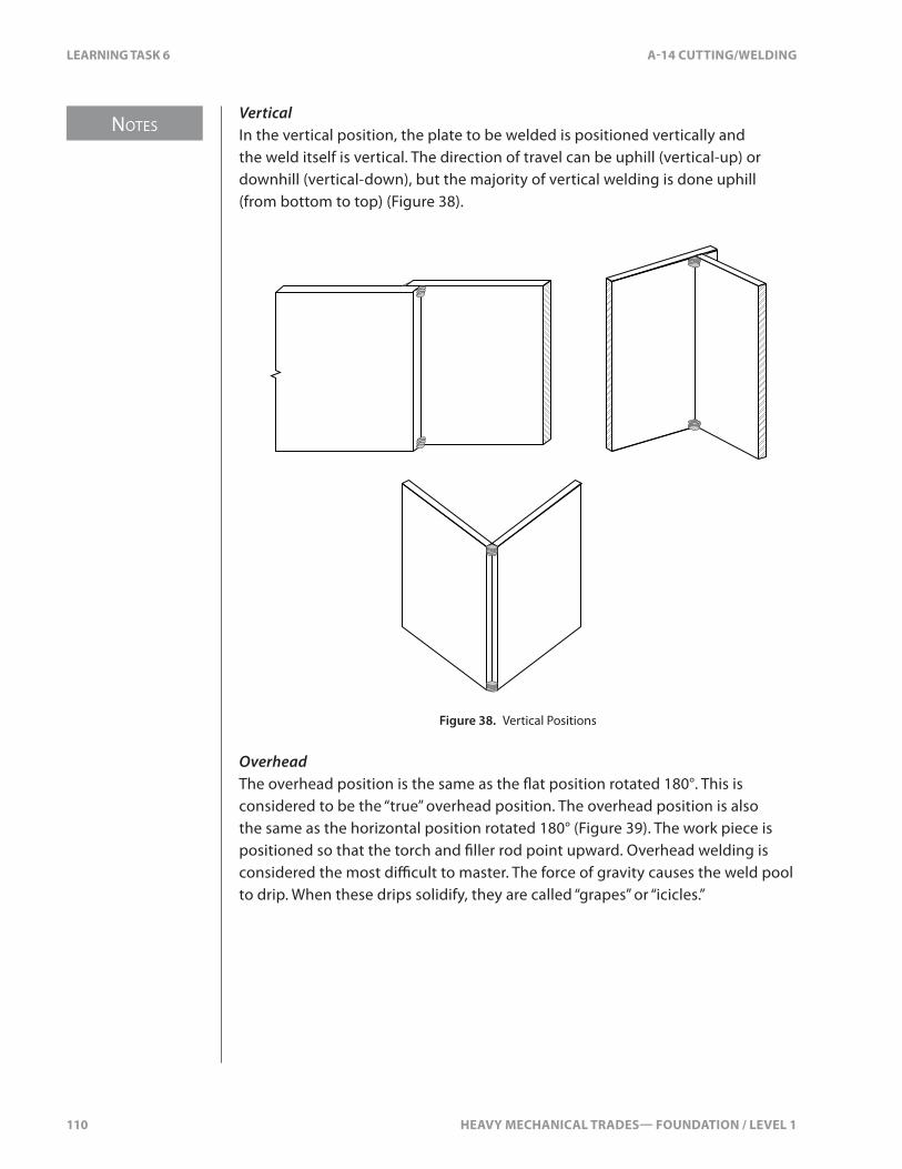
NOTES
110 HEAVY MECHANICAL TRADES— FOUNDATION / LEVEL 1
LEARNING TASK 6 A-14 CUTTING/WELDING
VerticalIn the vertical position, the plate to be welded is positioned vertically and the weld itself is vertical. The direction of travel can be uphill (vertical-up) or downhill (vertical-down), but the majority of vertical welding is done uphill (from bottom to top) (Figure 38).
Figure 38. Vertical Positions
OverheadThe overhead position is the same as the �at position rotated 180°. This is considered to be the “true” overhead position. The overhead position is also the same as the horizontal position rotated 180° (Figure 39). The work piece is positioned so that the torch and �ller rod point upward. Overhead welding is considered the most di�cult to master. The force of gravity causes the weld pool to drip. When these drips solidify, they are called “grapes” or “icicles.”
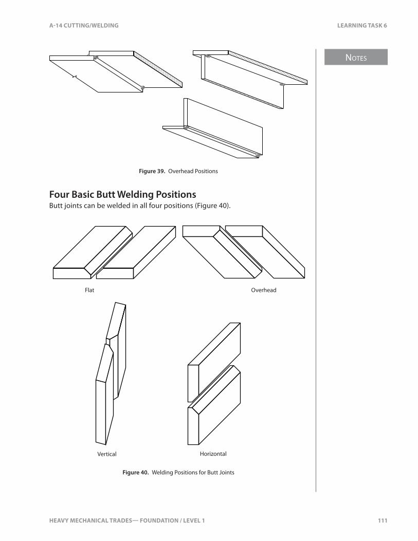
HEAVY MECHANICAL TRADES— FOUNDATION / LEVEL 1 111
NOTES
A-14 CUTTING/WELDING LEARNING TASK 6
Figure 39. Overhead Positions
Four Basic Butt Welding PositionsButt joints can be welded in all four positions (Figure 40).
Flat Overhead
HorizontalVertical
Figure 40. Welding Positions for Butt Joints

112 HEAVY MECHANICAL TRADES— FOUNDATION / LEVEL 1
SELF TEST 6 A-14 CUTTING/WELDING
SELF TEST 6
1. What is the name for the area of fusion where two pieces of metal have been joined?
a. slag
b. kerf
c. weld bead
d. �ller deposit
2. What is the main purpose of �ller metal in fusion welding?
a. to cool the weld pool
b. to create a bond
c. to add metal
d. to slow the progress of the weld
3. What thickness of metal is the single-vee butt joint used on?
a. 3 mm to 10 mm (1⁄8" to 3⁄8")
b. 6 mm to 19 mm (¼" to ¾")
c. 19 mm to 25 mm (¾" to 1")
d. 25 mm to 38 mm (1" to 1½")
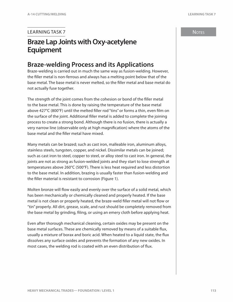
HEAVY MECHANICAL TRADES— FOUNDATION / LEVEL 1 113
NOTES
A-14 CUTTING/WELDING LEARNING TASK 7
LEARNING TASK 7
Braze Lap Joints with Oxy-acetylene Equipment
Braze-welding Process and its ApplicationsBraze-welding is carried out in much the same way as fusion-welding. However, the �ller metal is non-ferrous and always has a melting point below that of the base metal. The base metal is never melted, so the �ller metal and base metal do not actually fuse together.
The strength of the joint comes from the cohesion or bond of the �ller metal to the base metal. This is done by raising the temperature of the base metal above 427°C (800°F) until the melted �ller rod “tins” or forms a thin, even �lm on the surface of the joint. Additional �ller metal is added to complete the joining process to create a strong bond. Although there is no fusion, there is actually a very narrow line (observable only at high magni�cation) where the atoms of the base metal and the �ller metal have mixed.
Many metals can be brazed; such as cast iron, malleable iron, aluminum alloys, stainless steels, tungsten, copper, and nickel. Dissimilar metals can be joined; such as cast iron to steel, copper to steel, or alloy steel to cast iron. In general, the joints are not as strong as fusion-welded joints and they start to lose strength at temperatures above 260°C (500°F). There is less heat required and less distortion to the base metal. In addition, brazing is usually faster than fusion-welding and the �ller material is resistant to corrosion (Figure 1).
Molten bronze will �ow easily and evenly over the surface of a solid metal, which has been mechanically or chemically cleaned and properly heated. If the base metal is not clean or properly heated, the braze-weld �ller metal will not �ow or “tin” properly. All dirt, grease, scale, and rust should be completely removed from the base metal by grinding, �ling, or using an emery cloth before applying heat.
Even after thorough mechanical cleaning, certain oxides may be present on the base metal surfaces. These are chemically removed by means of a suitable �ux, usually a mixture of borax and boric acid. When heated to a liquid state, the �ux dissolves any surface oxides and prevents the formation of any new oxides. In most cases, the welding rod is coated with an even distribution of �ux.
NOTES
114 HEAVY MECHANICAL TRADES— FOUNDATION / LEVEL 1
LEARNING TASK 7 A-14 CUTTING/WELDING
Flux is also available in powder form and a plain �ller rod is dipped into the �ux during brazing. Coated rod is usually preferred as it eliminates the need to constantly interrupt the brazing procedure. When heated, the �ux melts and forms a liquid �lm. The �lm dissolves surface oxides or prevents them from forming and generally cleans the metal where the pieces are to be joined. The �ux �oats to the top of the puddle and, once solidi�ed, can be easily chipped o�.
Weld pool
Base metal
Brazing filler metal rod
Weld bead
Torch tip
Figure 1. Braze-welding
Filler MetalThe �ller rod used for most brazing is a non-ferrous alloy, containing roughly 60% copper, 40% zinc, and small amounts of tin, iron, manganese, and silicon. There are many other alloy combinations, such as silver solder, available for various base metals.
The rod is manufactured and coded the same way as steel �ller rod, with standard classi�cation codes and manufacturers’ trade names. The size of the rod is measured by the diameter of the �ller rod, not including the �ux coating (Figure 2).
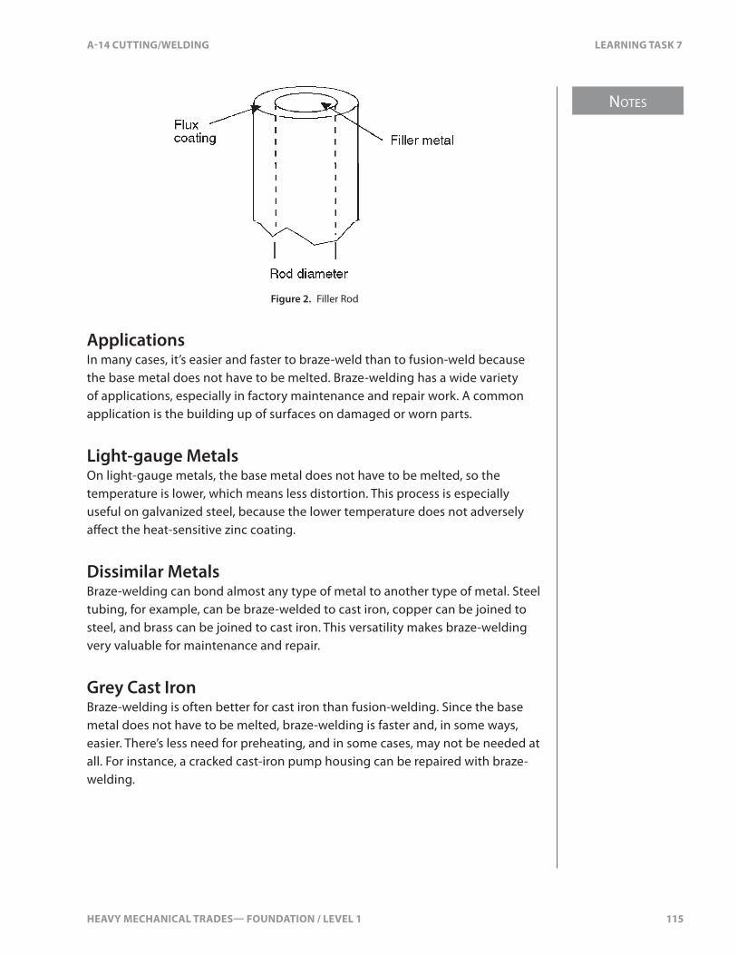
HEAVY MECHANICAL TRADES— FOUNDATION / LEVEL 1 115
NOTES
A-14 CUTTING/WELDING LEARNING TASK 7
Figure 2. Filler Rod
ApplicationsIn many cases, it’s easier and faster to braze-weld than to fusion-weld because the base metal does not have to be melted. Braze-welding has a wide variety of applications, especially in factory maintenance and repair work. A common application is the building up of surfaces on damaged or worn parts.
Light-gauge MetalsOn light-gauge metals, the base metal does not have to be melted, so the temperature is lower, which means less distortion. This process is especially useful on galvanized steel, because the lower temperature does not adversely a�ect the heat-sensitive zinc coating.
Dissimilar MetalsBraze-welding can bond almost any type of metal to another type of metal. Steel tubing, for example, can be braze-welded to cast iron, copper can be joined to steel, and brass can be joined to cast iron. This versatility makes braze-welding very valuable for maintenance and repair.
Grey Cast IronBraze-welding is often better for cast iron than fusion-welding. Since the base metal does not have to be melted, braze-welding is faster and, in some ways, easier. There’s less need for preheating, and in some cases, may not be needed at all. For instance, a cracked cast-iron pump housing can be repaired with braze-welding.
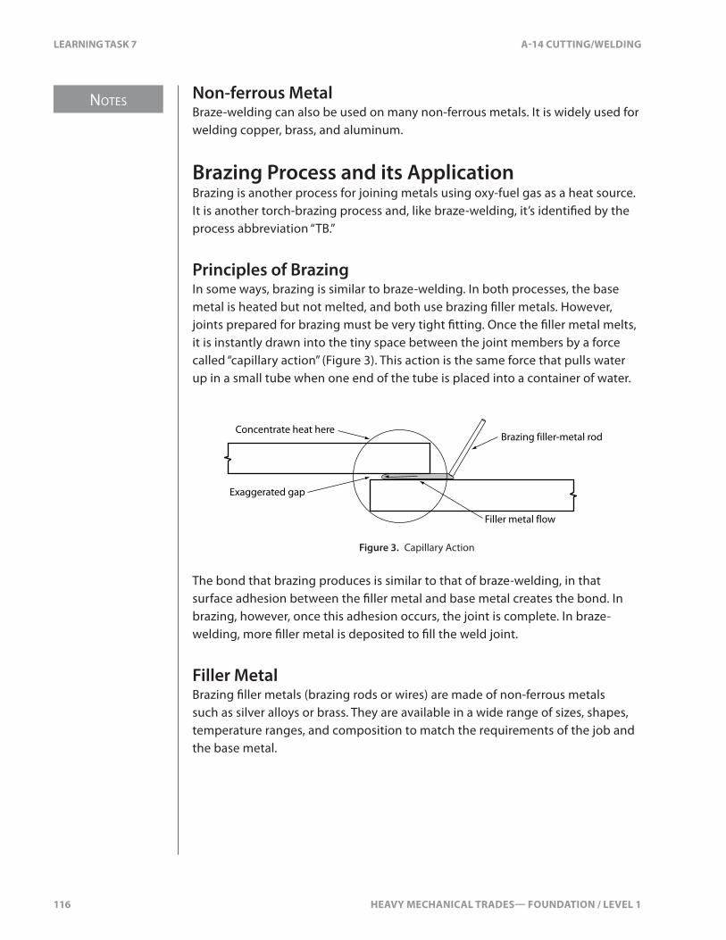
NOTES
116 HEAVY MECHANICAL TRADES— FOUNDATION / LEVEL 1
LEARNING TASK 7 A-14 CUTTING/WELDING
Non-ferrous MetalBraze-welding can also be used on many non-ferrous metals. It is widely used for welding copper, brass, and aluminum.
Brazing Process and its ApplicationBrazing is another process for joining metals using oxy-fuel gas as a heat source. It is another torch-brazing process and, like braze-welding, it’s identi�ed by the process abbreviation “TB.”
Principles of BrazingIn some ways, brazing is similar to braze-welding. In both processes, the base metal is heated but not melted, and both use brazing �ller metals. However, joints prepared for brazing must be very tight �tting. Once the �ller metal melts, it is instantly drawn into the tiny space between the joint members by a force called “capillary action” (Figure 3). This action is the same force that pulls water up in a small tube when one end of the tube is placed into a container of water.
Brazing filler-metal rod
Exaggerated gap
Concentrate heat here
Filler metal flow
Figure 3. Capillary Action
The bond that brazing produces is similar to that of braze-welding, in that surface adhesion between the �ller metal and base metal creates the bond. In brazing, however, once this adhesion occurs, the joint is complete. In braze-welding, more �ller metal is deposited to �ll the weld joint.
Filler MetalBrazing �ller metals (brazing rods or wires) are made of non-ferrous metals such as silver alloys or brass. They are available in a wide range of sizes, shapes, temperature ranges, and composition to match the requirements of the job and the base metal.
HEAVY MECHANICAL TRADES— FOUNDATION / LEVEL 1 117
NOTES
A-14 CUTTING/WELDING LEARNING TASK 7
All brazing �ller metals have melting temperatures above 450°C (840°F). The melting point of the base metals they’re used on is higher. The temperature 450°C (840°F) is the division between �ller metals classi�ed as brazing and those classi�ed as soldering. Filler metals with melting temperatures below 450°C (840°F) are called “solder” and, generally, they are softer and weaker than brazing �ller metals.
ApplicationsBrazing is widely used in production and maintenance work. It has the same versatility as braze-welding in that it can be used on a wide variety of ferrous and non-ferrous metals. It’s especially e�ective on complex shapes because of the way the �ller metal is “drawn in” to the joint by capillary action. Welded joints made by this process are strong and corrosion resistant.
Like braze-welding, brazing can be used to join both ferrous and non-ferrous metals and to join dissimilar metals. If the correct �ller rod is used, almost any metal can be brazed. As in braze-welding, the base metal is not melted, so brazing is especially e�ective on light-gauge metals that would be distorted by the high temperatures used in fusion-welding.
Because silver conducts electricity very well, silver alloy brazing is used to fabricate and repair electrical connections. For the same reason, it’s also used in the fabrication and repair of refrigeration and air-conditioning equipment.

118 HEAVY MECHANICAL TRADES— FOUNDATION / LEVEL 1
SELF TEST 7 A-14 CUTTING/WELDING
SELF TEST 7
1. What type of �ller rod is used for braze welding joints?
a. 60% copper 40% zinc
b. 60% tin 40% led
c. 40% copper 60% zinc
d. 40% tin 60% lead
2. What draws the �ller metal into the joint of the brazing process?
a. �ux
b. heat
c. capillary action
d. �ller rod
3. What is the minimum temperature of the base metal required when brazing?
a. 323°C (613°F)
b. 427°C (800°F)
c. 537°C (1000°F)
d. 648°C (1200°F)
4. What does the �ller rod for brazing contain?
a. 70% lead, 30% brass
b. 50% brass, 50% copper
c. 60% copper, 40% zinc
d. 70% brass, 30% zinc
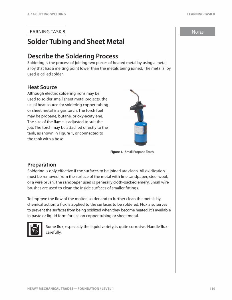
HEAVY MECHANICAL TRADES— FOUNDATION / LEVEL 1 119
NOTES
A-14 CUTTING/WELDING LEARNING TASK 8
LEARNING TASK 8
Solder Tubing and Sheet Metal
Describe the Soldering ProcessSoldering is the process of joining two pieces of heated metal by using a metal alloy that has a melting point lower than the metals being joined. The metal alloy used is called solder.
Heat SourceAlthough electric soldering irons may be used to solder small sheet metal projects, the usual heat source for soldering copper tubing or sheet metal is a gas torch. The torch fuel may be propane, butane, or oxy-acetylene. The size of the �ame is adjusted to suit the job. The torch may be attached directly to the tank, as shown in Figure 1, or connected to the tank with a hose.
Figure 1. Small Propane Torch
PreparationSoldering is only e�ective if the surfaces to be joined are clean. All oxidization must be removed from the surface of the metal with �ne sandpaper, steel wool, or a wire brush. The sandpaper used is generally cloth-backed emery. Small wire brushes are used to clean the inside surfaces of smaller �ttings.
To improve the �ow of the molten solder and to further clean the metals by chemical action, a �ux is applied to the surfaces to be soldered. Flux also serves to prevent the surfaces from being oxidized when they become heated. It’s available in paste or liquid form for use on copper tubing or sheet metal.
Some �ux, especially the liquid variety, is quite corrosive. Handle �ux carefully.
NOTES
120 HEAVY MECHANICAL TRADES— FOUNDATION / LEVEL 1
LEARNING TASK 8 A-14 CUTTING/WELDING
SolderTwo main classes of solder are hard solder and soft solder. Hard solder is an alloy of copper and zinc, while soft solder is made of tin and lead. Soft solder is generally used for joining copper tubing or sheet metal.
Soft solder is available in varying compositions such as 30/70, 50/50, or 60/40. The �rst number indicates the tin content, so solder with a 30/70 composition will be 30% tin and 70% lead. Pure tin has a melting point of about 232°C (450°F) while pure lead melts at about 327°C (620°F). A solder consisting of equal parts of tin and lead melts at about 212°C (415°F).
The higher the tin content, the stronger the solder joint. Solder containing a high content of lead is weak, but those containing a high content of tin are brittle. Combining the two in the right proportions produces a solder that is strong but not brittle. Lead-free solder is available as a replacement for lead-type solders.
Solder is available in bar or wire form. The wire form is available in varying diameters and may be either solid wire or have a hollow centre �lled with rosin-type or acid-type �ux. Popular diameters for wire core solder are 1⁄16 in., 3⁄32 in., and 1⁄8 in. The amount of solder to be used at each joint usually dictates the diameter of wire to use.
Wiring connections are to be soldered with rosin core solder only.
Describe the Procedures for SolderingSuccessful soldering of copper tubing with soft solder requires that you follow these steps:
1. Select a suitable solder. Of the many varieties you can choose from, one that contains more tin than lead will provide a strong joint provided that it’s not subjected to �exing. In general, most copper tube can be soldered with a soft solder with a 50/50 composition.
2. Use steel wool or emery cloth to clean all surfaces to be joined. Use a small wire brush to clean the interiors of copper socket �ttings that have small diameters. Large diameter �ttings may have their sockets cleaned with a small section of steel wool or emery cloth. Blow o� residue from the cleaning process. Do not touch the cleaned surfaces with your bare hands, as this will contaminate the surfaces.

HEAVY MECHANICAL TRADES— FOUNDATION / LEVEL 1 121
NOTES
A-14 CUTTING/WELDING LEARNING TASK 8
3. Apply �ux to all surfaces to be joined. Handle corrosive �ux very carefully. Flux should be applied as soon as possible to the areas that have been cleaned. Any lengthy delay in the application of �ux permits oxides to form on the surface of the metal. Cover the entire joining surfaces with a thin layer of �ux.
4. Fit the two joining surfaces and secure them so that no movement between them is possible. Be sure that the �tting is fully seated on the tube.
5. Apply heat gradually to the parts to be joined. Too much heat applied in one spot may burn the copper and make it brittle or cause cast copper �ttings to crack. Ply the torch back and forth, starting at the top and working downward. Continue applying heat until the metal is hot enough to melt the solder.
6. Now apply solder to the joint. The solder should melt the moment it makes contact with the heated copper, as illustrated in Figure 2. Remove the heat source from the joint and continue to add solder until the joint does not draw in any more solder. You should end up with a slight bead of solder showing at the shoulder of the �tting.
Never touch the solder wire with the heat source.
Figure 2. Soldering a Joint
7. Give the joint a quick wipe with a dry rag to remove any excess melted solder or �ux. Allow the joint to cool naturally for a minute or two, giving the solder a chance to solidify. If you cool the joint too quickly, you risk warping or cracking the �tting.
NOTES
122 HEAVY MECHANICAL TRADES— FOUNDATION / LEVEL 1
LEARNING TASK 8 A-14 CUTTING/WELDING
When the joint has cooled, wipe the entire joint area with a wet rag or shop towel to cool it down. Wash the entire area of the joint, making sure no �ux remains on the surfaces of the tubing or �tting.
The procedure for soldering sheet metal with soft solder is as follows:
1. Select a suitable solder. As with copper tubing, if you require a strong joint that will not need to �ex, choose a solder that has a high tin content. Sheet metal can be soldered using soft solder with a 50/50 composition; however 60/40 is more popular because it will form a stronger joint.
2. Use steel wool or emery cloth to clean all surfaces.
3. Apply �ux as soon as possible to the areas that have been cleaned. Flux penetrates and removes oxide formations on the surface of the metals.
Some of the paint-on acid-based �uxes suitable for use on metal sheet are very corrosive. Handle them carefully.
4. Fit the two joining surfaces and secure them so that no movement between them is possible.
5. Apply heat gradually to the metal. Too much heat applied in one spot may cause the metal to warp. Move the torch back and forth over the entire area of the joint. Continue applying heat until the metal is hot enough to melt the solder. Do not touch the �ame to the solder wire. The solder must be melted by the hot metal, not by the torch.
6. Apply solder to the joint (Figure 3). The solder should melt the moment it makes contact with the heated metal. Remove the heat from the joint and continue to add solder until the joint does not draw in any more solder. Solder �ows toward the heat. If two surfaces are hot enough to melt the solder, but one is hotter than the other, the solder will �ow toward the hotter surface. You should end up with a slight bead of solder showing at the shoulder or edge of the metal.
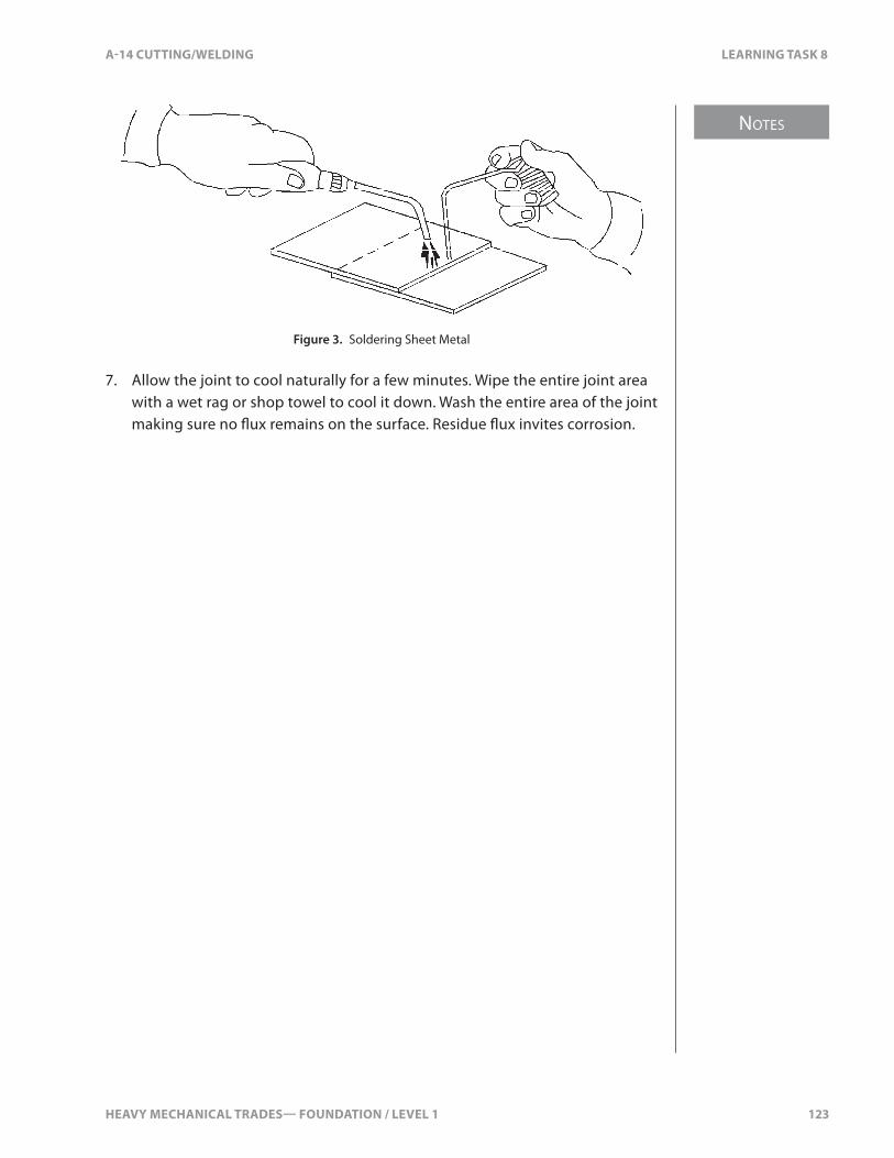
HEAVY MECHANICAL TRADES— FOUNDATION / LEVEL 1 123
NOTES
A-14 CUTTING/WELDING LEARNING TASK 8
Figure 3. Soldering Sheet Metal
7. Allow the joint to cool naturally for a few minutes. Wipe the entire joint area with a wet rag or shop towel to cool it down. Wash the entire area of the joint making sure no �ux remains on the surface. Residue �ux invites corrosion.

124 HEAVY MECHANICAL TRADES— FOUNDATION / LEVEL 1
SELF TEST 8 A-14 CUTTING/WELDING
SELF TEST 8
1. What does 40/60 solder mean?
a. 40% to 60% lead
b. 40% lead and 60% tin
c. 40% zinc and 60% lead
d. 40% tin and 60% lead
2. What type of solder is used on wire connections?
a. acid core solder
b. rosin core solder
c. solid core solder
d. 50/50 solder

HEAVY MECHANICAL TRADES— FOUNDATION / LEVEL 1 125
NOTES
A-14 CUTTING/WELDING LEARNING TASK 9
LEARNING TASK 9
Describe the Shielded Metal Arc Welding (SMAW) Process
SMAW Process and its ApplicationsPrinciples of SMAWShielded metal arc welding (SMAW) is commonly called “stick welding” or “electric arc welding.” An electric arc is the bridge of light and heat that develops when an electric current is forced to leap across a small gap in an electrical circuit. In the SMAW process, the welding equipment is designed to maintain this arc. The intense heat of the arc and metal transfer fuses the metals.
Electricity �ows through an electrical circuit because there is electrical “pressure” created by a generator at the power source. This electrical pressure is called “voltage” and is measured in volts (V). The �ow of electricity is called “current” and is measured in amperes (A).
In order to work, an electrical current must �ow through the conductors in a closed electrical circuit. If for some reason this circuit is broken (or “opened”), the �ow of electricity will stop. Electrical pressure (voltage) will continue to exist while the generator runs. As soon as the circuit is completed (“closed”), current will resume �ow.
The Arc Welding CircuitAn arc welding circuit is an electrical circuit that you can close or open by touching the electrode to the work piece or pulling it away (Figure 1). The SMAW welding circuit consists of:
• a welding power source• a work piece lead (cable) and ground clamp• an electrode lead (cable)• a welding electrode and electrode holder• the work piece
When you touch the electrode to the work piece and immediately withdraw it a short distance, the arc is struck and the electrical circuit is completed. The current �ows through the electrode, across the arc, through the work piece, through the ground clamp and work piece lead, and back to the power source (Figure 1). The metal table may or may not be part of the welding circuit, depending on the location of the ground clamp.

NOTES
126 HEAVY MECHANICAL TRADES— FOUNDATION / LEVEL 1
LEARNING TASK 9 A-14 CUTTING/WELDING
Workpiece lead
WorkpieceGroundclamp
Electrode holder
Electrode
Weldingpowersource
Metal work table
Electrode lead
+
–
Figure 1. Arc Welding Circuit
The SMAW ProcessWhen the power source for a welding circuit is turned on, but before the arc has been struck, the circuit is “open.” At this point the voltage or the potential in the circuit is at its maximum and is called the “open circuit voltage.” The moment you strike the arc, the circuit is “closed,” the voltage drops to what is called the “arc voltage,” and the current �ows through the welding circuit.
As this current crosses the arc from the electrode to the work piece, tremendous heat is generated, anywhere from 5500–6600°C (9900–11 900°F). The heat melts the end of the electrode and the base metal in the work piece directly beneath the arc, forming a pool of molten metal.
As the electrode melts, small particles of molten metal are carried across the arc stream and deposited in the molten pool on the base metal, forming the weld deposit. This weld deposit is actually a mixture of the melted electrode and the melted base metal. At the same time, the force of the arc digs into the work piece and provides the necessary depth of penetration for the weld.
ElectrodesThe electrodes used in the SMAW process are coated with a �ux. Most electrodes have a core that consists of a solid metal wire. For some applications, the core is a tube containing metal powders or other particles. The metal core conducts the electrical current to the arc and also provides the �ller metal for the weld joint. This �ller metal is deposited as the electrode is gradually consumed and as the Welder moves the arc over the work piece at the correct arc length and travel speed.
HEAVY MECHANICAL TRADES— FOUNDATION / LEVEL 1 127
NOTES
A-14 CUTTING/WELDING LEARNING TASK 9
The coating of the electrode helps keep the arc stable and concentrated on a precise point on the weld. The chemicals in the electrode coating provide the shielding required protecting the molten metal from contamination by the atmosphere. This is where the name “shielded metal arc welding” comes from.
Welding Power SourceThe welding machine that provides the power for arc welding is an important part of the process. Its proper name is “welding power source.” Welding power sources for SMAW might supply either direct current (DC) or alternating current (AC). Controls on the welding power source enable you to vary the current as required for di�erent welding tasks, materials, and positions.
Applications of SMAWThe SMAW process can meet almost any requirement for welding carbon, stainless and alloy steels, and cast iron. Its uses include manufacture, construction, maintenance, and repair in:
• shipbuilding• commercial transport and automotive• industrial and agricultural equipment• engineering applications• boiler and pressure vessels• piping and pipelines• bridge-building• building construction and structural applications
The Arc Welding StationMany arc welding tasks, both in training and on the job, take place at a welding station (Figure 2). The main parts of the station are:
• welding power source• metal work table• electrode lead (cable) and terminals• electrode holder• welding booth or welding screens• work lead (cable) and terminals• ventilation system• ground clamp or work piece connection
Localized fume extraction is becoming more common.

NOTES
128 HEAVY MECHANICAL TRADES— FOUNDATION / LEVEL 1
LEARNING TASK 9 A-14 CUTTING/WELDING
Metal work table
To exhaust fan
Non-�ammable curtainson all open sides
Weldingpower source
Concrete �oor
Figure 2. Welding Station
Welding Station InspectionThe welding station provides a safe work environment and protection for fellow workers. To maintain the e�ciency and safety of the station, it’s important that you get into the habit of completing a thorough inspection before starting any work.
When inspecting an arc welding station, the following points must be considered:
• Make sure that the welding power source is turned o� before proceeding further.
• Inspect all cables to make sure that they’re free from damage.
• Use channel iron to cover all cables that have to run across aisles. Wheeled machines such as lift trucks and pallet movers easily damage cables.
HEAVY MECHANICAL TRADES— FOUNDATION / LEVEL 1 129
NOTES
A-14 CUTTING/WELDING LEARNING TASK 9
• Check the electrode holder assembly carefully to make sure that: § The cable is fastened securely in the holder. § The holder insulation is in good condition. § The holder jaws are clean to ensure good electrical contact with the
electrode.
• Check that the connection between the work piece lead and the work piece or work table is secure to ensure that the ground clamp makes good electrical contact.
• Check that the welding booth or temporary screens have no holes that could expose people to the dangers of arc �ash.
• Check that the ventilation system is working, and that the ventilation pickup duct is placed so that fumes are removed before they reach the Welder’s breathing zone. This is very important if a fume extraction arm is used instead of a canopy (Figure 2).
• Make sure that there is an insulated hook to hang the electrode holder on when it is not in use.
• Make sure that there is an electrode stub receptacle.
Safety RequirementsDuring all welding processes, you must protect yourself from the sparks, heat, light, and fumes given o�. Each welding process also has its own special safety requirements. With oxy-fuel gas-welding and cutting processes, you must take extreme caution with the gases to prevent an explosion. With SMAW and other electrical welding processes such as GMAW, FCAW, and GTAW, you must take great care to protect against arc radiation and electric shock.
Potential hazards and protective measures with SMAW are:
• personal protective equipment (PPE)• arc burn• electric shock• �re and explosion prevention• safety requirements for operating electric welding equipment• toxic fumes/ventilation

NOTES
130 HEAVY MECHANICAL TRADES— FOUNDATION / LEVEL 1
LEARNING TASK 9 A-14 CUTTING/WELDING
Personal Protective EquipmentEye Protection for the Electrical Welding Processes
When you weld using an electrical process such as SMAW, you must take extreme care to protect your eyes. The infrared and ultraviolet rays that arc welding produces can cause serious and sometimes permanent injury to your eyes.
Exposing inadequately protected eyes to the welding arc can cause a burn called “arc �ash.” Even a one-second exposure at a distance of 0.5 m (20 in.) is enough to burn the eyes. WorkSafeBC recommends a minimum distance of 12 m (40 ft.) between the welding area and unprotected viewers.
Never look at an arc with the naked eye. If you receive an arc �ash, immediately report it to your instructor. Keep a minimum distance of 12 m (40 ft.) between an arc and the naked eye.
Welding HelmetsTo protect your eyes, face, and neck during arc welding, you must wear a welding helmet equipped with a dark �lter lens. These �lter lenses come in a range of di�erent shades (Figure 3), each with a di�erent number. Your choice of �lter lens depends on the level of current you are using, since this determines the intensity of the arc. Figure 3 lists �lter lens shade numbers recommended for di�erent current settings. These are suggestions only. If your eyes are sensitive, you might need a darker lens.
Filter lens shades recommended for level of current
Below 30 A No. 6
30–70 A No. 9
70–200 A No. 10
200–300 A No. 11
300–400 A No. 12
Over 400 A No. 13
Figure 3. Filter Lens Shades Recommended for Current Level
If your eyesight requires it, use a clear magnifying lens—also known as a “cheater lens.” These special lenses �t behind your �lter lens and take the place of reading glasses. They are available from welding supply companies.
Always check the �lter lens in your face shield or helmet before you start to weld to make sure it’s not cracked or broken. If it is cracked or chipped, replace it immediately.
HEAVY MECHANICAL TRADES— FOUNDATION / LEVEL 1 131
NOTES
A-14 CUTTING/WELDING LEARNING TASK 9
If you are in a work area where arc welding is being done, always wear approved safety glasses with side shields as protection from arc �ash and �ying debris.
The shade numbers for auto-darkening helmets are equivalent to those in Figure 3. Check the manufacturer’s literature to con�rm the correct adjustment of your helmet.
Arc BurnThe infrared and ultraviolet radiation that arc welding produces can damage improperly protected eyes and severely burn your skin. For this reason, you must wear the proper protective clothing and equipment during SMAW and other electrical welding processes.
The amount of protective clothing you require will depend on how much welding you’re doing, and on the welding positions you use. When welding, all parts of your body must be covered. Depending on the welding position and type of welding, you’ll need either full or partial �ame-resistant clothing. This could include jackets, sleeves, aprons, leggings, and anklets. Do not wear synthetics such as Nylon or Dacron, as they will melt and cling to your skin as they burn. Your standard protective clothing for arc welding must also include a peaked cap, leather gloves, and safety boots.
If you’re burned while arc welding, get medical attention immediately.
Electric ShockThe electrical currents used in SMAW are very high. If you become part of the electrical circuit at any point, you could receive an electric shock severe enough to kill you. Even a small shock that is not immediately fatal could be su�cient to cause you to jerk and fall, leading to a serious injury.
One of the main factors contributing to electric shock (fatal or otherwise) is dampness. Any dampness between your body and an energized part of the equipment provides a ground conductor that could carry the current to your body. The best way to prevent being grounded in this way is to make sure that your hands and clothing are dry. Do not weld if conditions require you to stand in water or on a wet surface. Instead, �nd a dry board or rubber mat to stand on.
NOTES
132 HEAVY MECHANICAL TRADES— FOUNDATION / LEVEL 1
LEARNING TASK 9 A-14 CUTTING/WELDING
Initial Electrical Isolation of Shock VictimsIf one of your fellow workers receives an electric shock, it’s essential to remove the victim from contact with the power source as soon as possible. Do not touch the victim if he or she is still in contact with the live source of electrical power. To do so, or even to come close to the victim, could put you in danger of electrical shock and leave you powerless to help.
If you know that the power switch is nearby, disconnect the circuit. If you do not know where the power switch is or if it is not close by, send someone else to disconnect the power, and at the same time, send for emergency medical aid. In the meantime, �nd some non-conductive material such as a length of dry wood, some rope, or a blanket and try to pull or pry the conductor from the victim. For more detailed instructions in the procedures to use in cases of electrical shock, refer to WorkSafeBC’s website, www.worksafebc.com, and click on OHS Regulation under the “Quick Links.”
Fire PreventionElectrical welding (such as SMAW) poses as great a �re hazard as oxy-fuel welding.
Follow these safety points:
• Make sure that your workplace is as free as possible of combustible materials before you begin to weld.
• If �ammable materials cannot be removed from the work area, be sure they are protected adequately from sparks and slag before you start to weld. Assigning a �re watcher is highly recommended.
• Do not weld anywhere near containers of �ammable liquids.• Know the locations and types of �re extinguishers in your immediate
work area and how to use them.
Safety Requirements for Operating Electrical Welding EquipmentThe greatest electrical hazard for Welders is from their electric welding power sources. For this reason, every time you work with these machines, you must follow all the standard safety precautions.
In addition, all switches must be clearly marked, all electrical tools and equipment must be properly grounded, and metal ladders must be kept away from any source of electrical power.

HEAVY MECHANICAL TRADES— FOUNDATION / LEVEL 1 133
NOTES
A-14 CUTTING/WELDING LEARNING TASK 9
WorkSafeBC publishes a useful guide called Working Safely Around Electricity. It’s also available on the Web at:
http://www.worksafebc.com/publications/health_and_safety/by_ topic/assets/pdf/electricity.pdf
Maintenance and EquipmentThe Welder who is about to use a welding power source is responsible for making sure that the machine is in a safe operating condition. The wiring, switches, controls, and cables must all be thoroughly checked before use. Preventive maintenance (such as internal cleaning and lubrication) must be carried out at regular intervals.
In most welding shops, the electrical power for arc welding equipment is 230 V, 460 V, or 575 V. These are high voltages that can easily deliver severe or fatal shocks. When performing any internal preventive maintenance work on electrical welding equipment, observe the following rules:
• All troubleshooting and maintenance of welding power sources must be done only on open circuits. Make sure that the main power supply disconnect switch is open and locked out (Figure 4).
• Do not work on main power lines, junction boxes, or fuses. Only an electrician quali�ed in accordance with the requirements of the Canadian Electrical Code can do this. The Welder’s maintenance responsibilities end with the welding power source.
Figure 4. Lockout
NOTES
134 HEAVY MECHANICAL TRADES— FOUNDATION / LEVEL 1
LEARNING TASK 9 A-14 CUTTING/WELDING
When you connect an electrical welding power source to its main power supply, it’s extremely important to make sure that the main power circuit is properly grounded. Without proper grounding, any stray current that develops could give you or another worker a severe or even fatal shock. If you have one hand on an inadequately grounded power supply in which a current is �owing and you accidentally touch a grounded metal object such as a switch box, you become part of the electrical circuit. The resulting electric shock could be fatal.
Without proper grounding, stray current can also damage cranes, motors, and controls as well as computerized equipment.
Welding CablesCheck the cables on a welding power source every time you use it. Never use electrical current that is more than the rated capacity of the welding cables on your power source. Not only is this uneconomical but, more importantly, it causes overheating and rapid deterioration of the insulation.
Faulty insulation is a hazard. If exposed sections of cable come in contact with any grounded metal object in the welding circuit, they could create an arc, which could in turn ignite any �ammable materials in the area.
Make inspection of the cables a standard part of your inspection of welding equipment. If the cables are in good condition, you can use them. If they are not, take these steps:
• Make sure the main power source is disconnected or locked out.• If there are surface cracks in the insulation, repair them with electrical
tape before starting the machine.• If there are breaks in the insulation that expose any wire, do not try to
repair it. Replace the cable with one that’s in good condition.
Electrode HoldersYour SMAW electrode and electrode holder are a part of the welding circuit. When the welding power source is on but you are not welding, always be extremely careful to remove the electrode from the holder so that the live electrode will not accidentally make contact with the surrounding metal and cause arc strikes. Arc strikes could result in damage to your work or cause �re or personal injury.
Your welding booth should have an insulated hook on which to hang the electrode holder. Always use the hook to prevent a hazardous situation from arising.
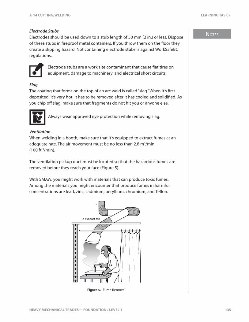
HEAVY MECHANICAL TRADES— FOUNDATION / LEVEL 1 135
NOTES
A-14 CUTTING/WELDING LEARNING TASK 9
Electrode StubsElectrodes should be used down to a stub length of 50 mm (2 in.) or less. Dispose of these stubs in �reproof metal containers. If you throw them on the �oor they create a slipping hazard. Not containing electrode stubs is against WorkSafeBC regulations.
Electrode stubs are a work site contaminant that cause �at tires on equipment, damage to machinery, and electrical short circuits.
SlagThe coating that forms on the top of an arc weld is called “slag.” When it’s �rst deposited, it’s very hot. It has to be removed after it has cooled and solidi�ed. As you chip o� slag, make sure that fragments do not hit you or anyone else.
Always wear approved eye protection while removing slag.
VentilationWhen welding in a booth, make sure that it’s equipped to extract fumes at an adequate rate. The air movement must be no less than 2.8 m3/min (100 ft.3/min).
The ventilation pickup duct must be located so that the hazardous fumes are removed before they reach your face (Figure 5).
With SMAW, you might work with materials that can produce toxic fumes. Among the materials you might encounter that produce fumes in harmful concentrations are lead, zinc, cadmium, beryllium, chromium, and Te�on.
To exhaust fan
Figure 5. Fume Removal
NOTES
136 HEAVY MECHANICAL TRADES— FOUNDATION / LEVEL 1
LEARNING TASK 9 A-14 CUTTING/WELDING
Always be sure you know the metallic and chemical composition of the materials and electrodes you’re welding with. You must always be fully aware of the possibilities of toxic gas fumes in any location. Many toxic fumes cannot be easily identi�ed by smell, and they can accumulate undetected in areas where you’re welding. You might need to use special detection equipment to determine whether harmful concentrations exist.
Operate engine-driven welding power sources in open and well-ventilated outside areas or vent the exhaust and heat to the outdoors. Engine exhaust is harmful to health and a risk to life.
SummaryAs you prepare to weld, remember these safety points:
• Always turn o� your welding power source when not in use.• Wear gloves when handling arc welding equipment.• Keep all equipment dry and do not work in damp or wet conditions.• Make sure that the work piece or work table is properly grounded.• Do not overload the welding cables.• Remove the electrode from the electrode holder before putting the
holder down.• Switch the welding power source o� when you’re �nished working.

HEAVY MECHANICAL TRADES— FOUNDATION / LEVEL 1 137
A-14 CUTTING/WELDING SELF TEST 9
SELF TEST 9
1. When is the electrical circuit closed, in the SMAW process?
a. the power supply is turned on
b. the electrode is inserted in the hold
c. the arc is struck
d. the parent metal begins to melt
2. What helmet �lter lens should be selected for 70 to 200 Amps of current?
a. #12 lens
b. #11 lens
c. #10 lens
d. #9 lens
3. What is arc burn?
a. skin burns from sparks
b. skin burns from welding radiation
c. skin burns from contacting the metal
d. skin burns from the electrodes
4. What �lter lens shade is recommended when SMAW at 100A?
a. 6
b. 9
c. 10
d. 13

138 HEAVY MECHANICAL TRADES— FOUNDATION / LEVEL 1

HEAVY MECHANICAL TRADES— FOUNDATION / LEVEL 1 139
NOTES
A-14 CUTTING/WELDING LEARNING TASK 10
LEARNING TASK 10
Identify Shielded Metal Arc Welding Equipment
Types of Current and Their ApplicationsElectrical current is the �ow of electrons through a conductor. This electron �ow is from the negative pole to the positive pole. The current can be either alternating current (AC) or direct current (DC). Each type has di�erent characteristics and is suitable for di�erent welding applications. Welding power sources can be designed to produce both types of current, making them more versatile.
SMAW electrodes are designed for use with either AC or DC current, and some types can be used with both. The type of welding current will a�ect your choice of electrode. To develop good welding techniques, it’s essential to know the di�erences between the two types of current.
In SMAW, the type of welding current can a�ect:
• polarity of the work piece and the electrode• heat that is distributed to the work piece and the electrode• rate at which the electrode is deposited in the weld pool• depth of penetration of the weld deposit• occurrence of arc blow
Alternating CurrentThe �ow of alternating current reverses direction 120 times per second. A complete direction change from zero to maximum volts at one pole, then back to zero volts and up to maximum voltage at the other pole, is called a “cycle.” Most electrical utility companies distribute alternating current at 60 cycles per second. This means that 60 times a second, the voltage reaches a maximum in one direction and 60 times per second it reaches a maximum in the other direction. The current is said to be operating at 60 hertz (cycles per second). The symbol for alternating current (AC) is “~.”
Some of the characteristics of alternating current can be represented in the form of a sine wave diagram (Figure 1).
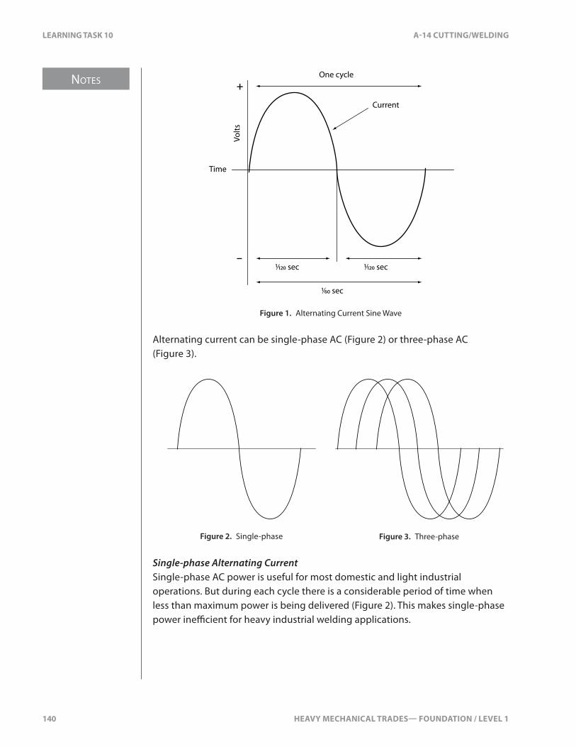
NOTES
140 HEAVY MECHANICAL TRADES— FOUNDATION / LEVEL 1
LEARNING TASK 10 A-14 CUTTING/WELDING
Time
Volts
One cycle
1⁄60 sec
1⁄120 sec 1⁄120 sec
+
–
Current
Figure 1. Alternating Current Sine Wave
Alternating current can be single-phase AC (Figure 2) or three-phase AC (Figure 3).
Figure 2. Single-phase Figure 3. Three-phase
Single-phase Alternating CurrentSingle-phase AC power is useful for most domestic and light industrial operations. But during each cycle there is a considerable period of time when less than maximum power is being delivered (Figure 2). This makes single-phase power ine�cient for heavy industrial welding applications.

HEAVY MECHANICAL TRADES— FOUNDATION / LEVEL 1 141
NOTES
A-14 CUTTING/WELDING LEARNING TASK 10
Three-phase Alternating CurrentThree-phase AC power is more often used in industry. In three-phase AC power, there are three single-phase currents. These are timed to start at regular intervals from each other (Figure 3). The advantage of three-phase power is that even though one phase may be delivering only minimum power, one of the other two phases will be delivering nearly maximum power. Welding power sources that use three-phase power produce a smoother arc than single-phase equipment.
Direct CurrentWith direct current (Figure 4), the electrons in a circuit �ow steadily in one direction only, from the negative pole to the positive pole. DC generators produce this type of current, with batteries or by rectifying AC current.
Time
Volts
Current
Figure 4. Direct Current
PolarityElectron �ow in an electrical circuit is always from the negative pole to the positive pole. The practical e�ects of this for welding are important with DC welding current (Figure 5).
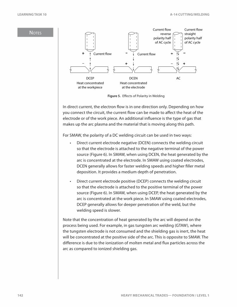
NOTES
142 HEAVY MECHANICAL TRADES— FOUNDATION / LEVEL 1
LEARNING TASK 10 A-14 CUTTING/WELDING
Current flow
Heat concentratedat the workpiece
Heat concentratedat the electrode
Current flow
Current flowreverse
polarity halfof AC cycle
Current flowstraightpolarity halfof AC cycle
DCEP DCEN AC
+
–
+
–+
–
+
–
Figure 5. Effects of Polarity in Welding
In direct current, the electron �ow is in one direction only. Depending on how you connect the circuit, the current �ow can be made to a�ect the heat of the electrode or of the work piece. An additional in�uence is the type of gas that makes up the arc plasma and the material that is moving along this path.
For SMAW, the polarity of a DC welding circuit can be used in two ways:
• Direct current electrode negative (DCEN) connects the welding circuit so that the electrode is attached to the negative terminal of the power source (Figure 6). In SMAW, when using DCEN, the heat generated by the arc is concentrated at the electrode. In SMAW using coated electrodes, DCEN generally allows for faster welding speeds and higher �ller metal deposition. It provides a medium depth of penetration.
• Direct current electrode positive (DCEP) connects the welding circuit so that the electrode is attached to the positive terminal of the power source (Figure 6). In SMAW, when using DCEP, the heat generated by the arc is concentrated at the work piece. In SMAW using coated electrodes, DCEP generally allows for deeper penetration of the weld, but the welding speed is slower.
Note that the concentration of heat generated by the arc will depend on the process being used. For example, in gas tungsten arc welding (GTAW), where the tungsten electrode is not consumed and the shielding gas is inert, the heat will be concentrated at the positive side of the arc. This is opposite to SMAW. The di�erence is due to the ionization of molten metal and �ux particles across the arc as compared to ionized shielding gas.
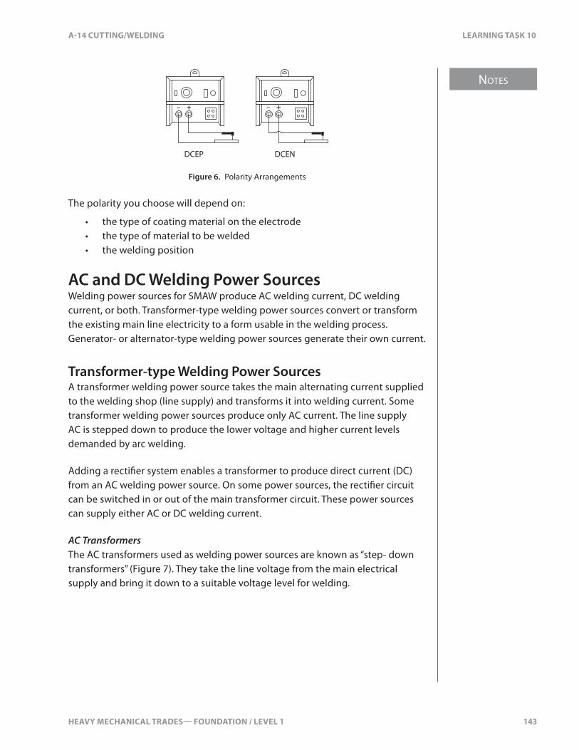
HEAVY MECHANICAL TRADES— FOUNDATION / LEVEL 1 143
NOTES
A-14 CUTTING/WELDING LEARNING TASK 10
DCEP DCEN
– + – +
Figure 6. Polarity Arrangements
The polarity you choose will depend on:
• the type of coating material on the electrode• the type of material to be welded• the welding position
AC and DC Welding Power SourcesWelding power sources for SMAW produce AC welding current, DC welding current, or both. Transformer-type welding power sources convert or transform the existing main line electricity to a form usable in the welding process. Generator- or alternator-type welding power sources generate their own current.
Transformer-type Welding Power SourcesA transformer welding power source takes the main alternating current supplied to the welding shop (line supply) and transforms it into welding current. Some transformer welding power sources produce only AC current. The line supply AC is stepped down to produce the lower voltage and higher current levels demanded by arc welding.
Adding a recti�er system enables a transformer to produce direct current (DC) from an AC welding power source. On some power sources, the recti�er circuit can be switched in or out of the main transformer circuit. These power sources can supply either AC or DC welding current.
AC TransformersThe AC transformers used as welding power sources are known as “step- down transformers” (Figure 7). They take the line voltage from the main electrical supply and bring it down to a suitable voltage level for welding.
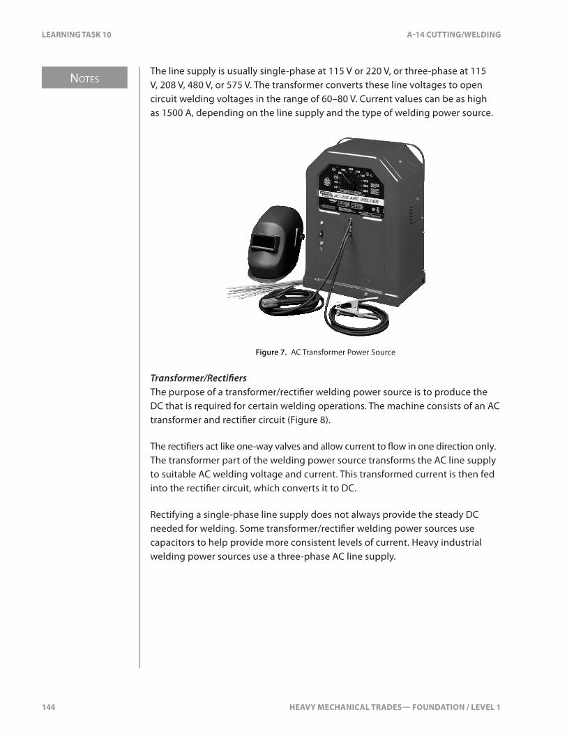
NOTES
144 HEAVY MECHANICAL TRADES— FOUNDATION / LEVEL 1
LEARNING TASK 10 A-14 CUTTING/WELDING
The line supply is usually single-phase at 115 V or 220 V, or three-phase at 115 V, 208 V, 480 V, or 575 V. The transformer converts these line voltages to open circuit welding voltages in the range of 60–80 V. Current values can be as high as 1500 A, depending on the line supply and the type of welding power source.
Figure 7. AC Transformer Power Source
Transformer/Recti�ersThe purpose of a transformer/recti�er welding power source is to produce the DC that is required for certain welding operations. The machine consists of an AC transformer and recti�er circuit (Figure 8).
The recti�ers act like one-way valves and allow current to �ow in one direction only. The transformer part of the welding power source transforms the AC line supply to suitable AC welding voltage and current. This transformed current is then fed into the recti�er circuit, which converts it to DC.
Rectifying a single-phase line supply does not always provide the steady DC needed for welding. Some transformer/recti�er welding power sources use capacitors to help provide more consistent levels of current. Heavy industrial welding power sources use a three-phase AC line supply.

HEAVY MECHANICAL TRADES— FOUNDATION / LEVEL 1 145
NOTES
A-14 CUTTING/WELDING LEARNING TASK 10
Figure 8. Transformer/Rectifier Welding Power Source
DC Transformer/Recti�er ControlThe current control on a transformer/recti�er is the same as that on an AC transformer welding power source. Generally, there are coarse current adjustments in low, medium, and high ranges. There are also �ner adjustments to match the current to variables such as electrode type and size, metal thickness, and welding position.
Some transformer/recti�ers also have a switch that controls the polarity of the circuit. This allows you to choose an electrode negative or electrode positive circuit to match the job requirements without having to change the leads on the machine.
Avoid changing welding current range control settings or polarity switches under load. Most �ne-adjust dial controls can be adjusted while welding.
AC/DC Transformer/Recti�ersSome transformer/recti�ers can provide both transformed AC current and recti�ed DC current. These welding power sources have a switch that allows the transformed current to bypass the recti�er circuit when you need AC current. Machines with this capability are called “AC/DC welding power sources.”
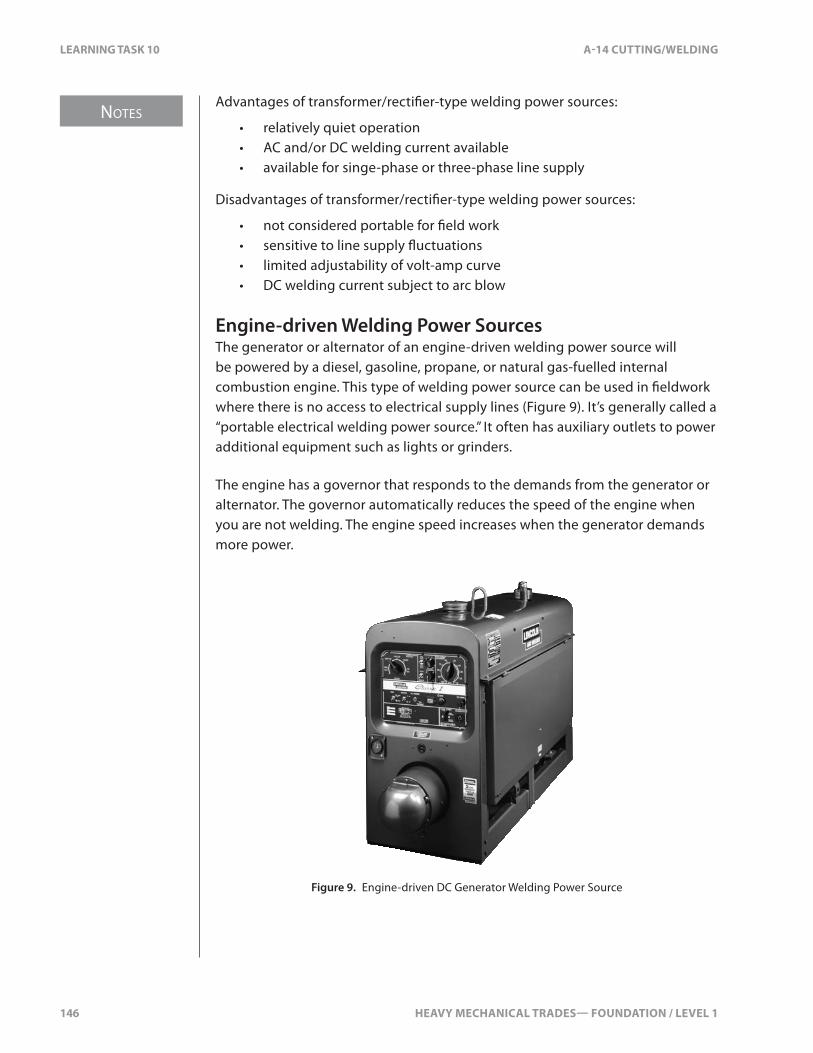
NOTES
146 HEAVY MECHANICAL TRADES— FOUNDATION / LEVEL 1
LEARNING TASK 10 A-14 CUTTING/WELDING
Advantages of transformer/recti�er-type welding power sources:
• relatively quiet operation• AC and/or DC welding current available• available for singe-phase or three-phase line supply
Disadvantages of transformer/recti�er-type welding power sources:
• not considered portable for �eld work• sensitive to line supply �uctuations• limited adjustability of volt-amp curve• DC welding current subject to arc blow
Engine-driven Welding Power SourcesThe generator or alternator of an engine-driven welding power source will be powered by a diesel, gasoline, propane, or natural gas-fuelled internal combustion engine. This type of welding power source can be used in �eldwork where there is no access to electrical supply lines (Figure 9). It’s generally called a “portable electrical welding power source.” It often has auxiliary outlets to power additional equipment such as lights or grinders.
The engine has a governor that responds to the demands from the generator or alternator. The governor automatically reduces the speed of the engine when you are not welding. The engine speed increases when the generator demands more power.
Figure 9. Engine-driven DC Generator Welding Power Source
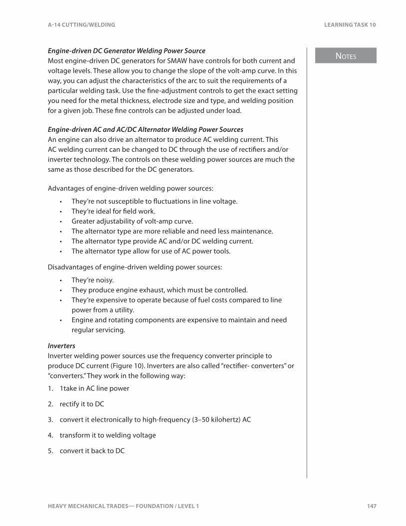
HEAVY MECHANICAL TRADES— FOUNDATION / LEVEL 1 147
NOTES
A-14 CUTTING/WELDING LEARNING TASK 10
Engine-driven DC Generator Welding Power SourceMost engine-driven DC generators for SMAW have controls for both current and voltage levels. These allow you to change the slope of the volt-amp curve. In this way, you can adjust the characteristics of the arc to suit the requirements of a particular welding task. Use the �ne-adjustment controls to get the exact setting you need for the metal thickness, electrode size and type, and welding position for a given job. These �ne controls can be adjusted under load.
Engine-driven AC and AC/DC Alternator Welding Power SourcesAn engine can also drive an alternator to produce AC welding current. This AC welding current can be changed to DC through the use of recti�ers and/or inverter technology. The controls on these welding power sources are much the same as those described for the DC generators.
Advantages of engine-driven welding power sources:
• They’re not susceptible to �uctuations in line voltage.• They’re ideal for �eld work.• Greater adjustability of volt-amp curve.• The alternator type are more reliable and need less maintenance.• The alternator type provide AC and/or DC welding current.• The alternator type allow for use of AC power tools.
Disadvantages of engine-driven welding power sources:
• They’re noisy.• They produce engine exhaust, which must be controlled.• They’re expensive to operate because of fuel costs compared to line
power from a utility.• Engine and rotating components are expensive to maintain and need
regular servicing.
InvertersInverter welding power sources use the frequency converter principle to produce DC current (Figure 10). Inverters are also called “recti�er- converters” or “converters.” They work in the following way:
1. 1take in AC line power
2. rectify it to DC
3. convert it electronically to high-frequency (3–50 kilohertz) AC
4. transform it to welding voltage
5. convert it back to DC

NOTES
148 HEAVY MECHANICAL TRADES— FOUNDATION / LEVEL 1
LEARNING TASK 10 A-14 CUTTING/WELDING
At the heart of the inverter is a high-frequency transformer. Remember that 1 hertz is one single cycle in one second. Domestic AC power operates at 60 hertz.
A conventional transformer operating at 60 hertz would weigh 19.5 kg (42 lb.). It would operate at 90% e�ciency and produce a heat loss of 10%.
An equivalent inverter operating at 200 000 hertz would weigh 1.5 kg (31⁄3 lb.). It would operate at 98% e�ciency and produce a heat loss of only 2%.
Inverter welding power sources operate in the region of 20 000 hertz. But their electrical e�ciency is still remarkable when compared to old technology. Inverters can operate on either single-phase or three-phase power.
The use of high-frequency current in the conversion means that all of the components are electronic. This reduces size and weight and increases electrical e�ciency. A standard transformer/recti�er can lose as much as 55% of the incoming power, while the energy loss with an inverter can be as low as 15%.
A traditional 300 A transformer/recti�er weighs approximately 360 kg (800 lb.). An inverter version weighs less than 40 kg (85 lb.).
1
2
3
4
5
6
7
input line voltage 60 cycles per second (Hz)
rectifier: DC ripple current
filter: smooth DC current
inverter: high-frequency AC current 20 000 Hz
transformer: low-voltage high-frequency AC current
rectifier: ripple DC low-voltage current
filter: smooth low-voltage welding current
Figure 10. Process Steps in an Inverter Power Source

HEAVY MECHANICAL TRADES— FOUNDATION / LEVEL 1 149
NOTES
A-14 CUTTING/WELDING LEARNING TASK 10
Advantages of inverter-type welding power sources:
• Energy-e�cient.• Loss is minimal and energy is only used when there is an arc.• The cooling fan is thermostatically controlled.• Their light weight means they can be moved between work sites.• Small size saves �oor space.• Built-in programs allow a limitless number of custom welding currents.
Many can be connected to a laptop computer and be reprogrammed for any new welding process developed.
• Arc blow is minimized.• Many can adapt to any input current from single-phase to higher voltage
three-phase without any adjustment.• They compensate for slight variations in voltage from the utility.
Duty CycleThe duty cycle is a way of rating a welding power source. The duty cycle is the length of time a welding power source can be used continuously at its rated capacity during any 10-minute period.
The length of time is expressed as a percentage of the 10-minute period. For example, if you need a welding power source that can be used at its maximum rated capacity for 10 minutes out of every 10 minutes, then you require a 100% duty cycle.
Most manual arc welding power sources are rated at a current output of 200 A, 300 A, or 400 A and a duty cycle of 60%. This means that they can be used at their rated current output for 6 minutes out of every 10.
When you’re welding, you’ll also have to spend time on other tasks such as preparing the work piece, changing electrodes, and cleaning and inspecting the �nished weld. This means that operating with less than 100% duty cycle is quite acceptable.
Smaller power sources, such as those used for light industrial or home use, are normally in the range of 150 A output with a 20–30% duty cycle.
The duty cycle rating tells you the percentage of time you can use the power source at its maximum rated current output. This means that at lower settings, the power source can be used for a longer continuous period. Manufacturers usually supply a graph that shows the length of time you can use the power source at a given current setting (Figure 11).

NOTES
150 HEAVY MECHANICAL TRADES— FOUNDATION / LEVEL 1
LEARNING TASK 10 A-14 CUTTING/WELDING
The graph shows that, at a rated output of 250 A, the duty cycle is 30%. At 200 A it is 40%, and at 150 A it is 75%. At the bottom end, the graph shows that at 140 A, the power source has a 100% duty cycle. However, no welding power source should be used continuously unless it has an o�cial 100% duty cycle.
Exceeding the duty cycle guidelines for a power source will cause overheating of the internal components and permanent damage.
% Duty cycle
Wel
ding
am
pere
s
1580
100
150
200
250
300
20 30 40 50 60 70 80 90
Figure 11. Duty Cycle Graph
Under normal operation with SMAW, the time spent welding (including the time spent chipping, cleaning, inspecting, and changing electrodes) will not exceed a 60% duty cycle.
General Maintenance of Welding Power SourcesFollow these maintenance tips:
• See the manufacturer’s operating manual for correct information.• Maintain a regular preventive maintenance schedule.• At least twice a year, electrically lock out or disconnect the power
source and clean as recommended by the manufacturer. If you use compressed air, blow with low velocity and use personal protective equipment.
• Watch out for rodent nests—Hantavirus is a risk.
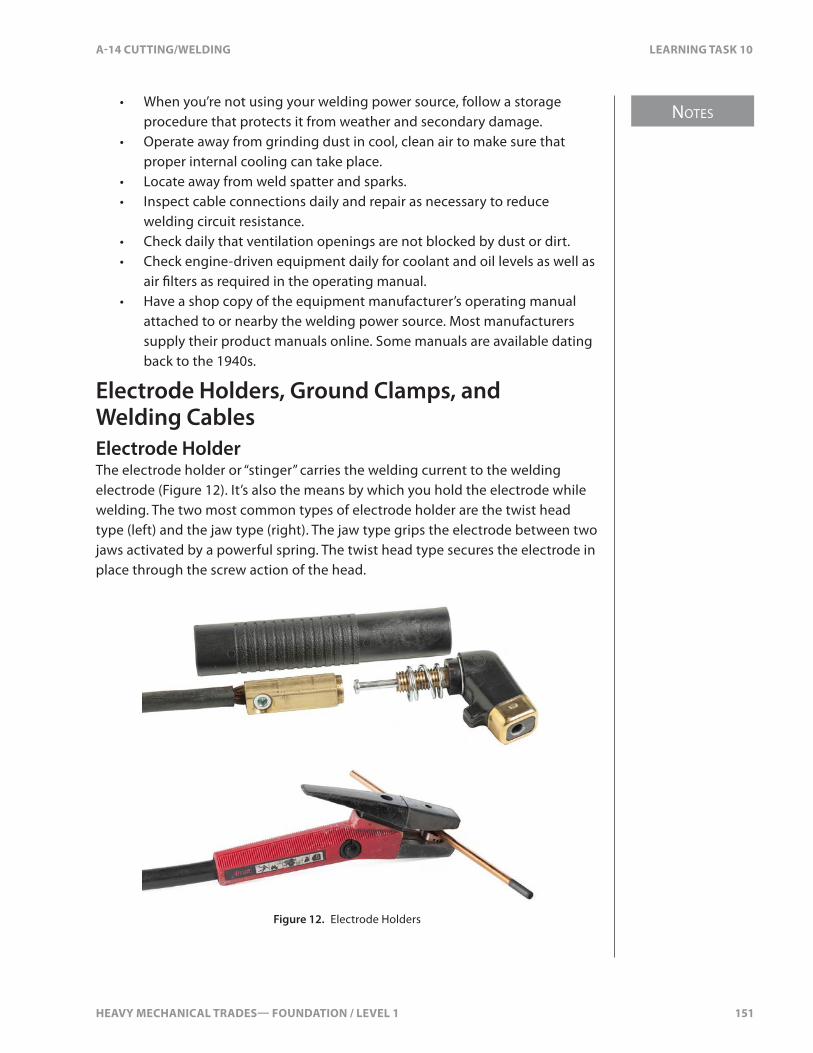
HEAVY MECHANICAL TRADES— FOUNDATION / LEVEL 1 151
NOTES
A-14 CUTTING/WELDING LEARNING TASK 10
• When you’re not using your welding power source, follow a storage procedure that protects it from weather and secondary damage.
• Operate away from grinding dust in cool, clean air to make sure that proper internal cooling can take place.
• Locate away from weld spatter and sparks.• Inspect cable connections daily and repair as necessary to reduce
welding circuit resistance.• Check daily that ventilation openings are not blocked by dust or dirt.• Check engine-driven equipment daily for coolant and oil levels as well as
air �lters as required in the operating manual.• Have a shop copy of the equipment manufacturer’s operating manual
attached to or nearby the welding power source. Most manufacturers supply their product manuals online. Some manuals are available dating back to the 1940s.
Electrode Holders, Ground Clamps, and Welding CablesElectrode HolderThe electrode holder or “stinger” carries the welding current to the welding electrode (Figure 12). It’s also the means by which you hold the electrode while welding. The two most common types of electrode holder are the twist head type (left) and the jaw type (right). The jaw type grips the electrode between two jaws activated by a powerful spring. The twist head type secures the electrode in place through the screw action of the head.
Figure 12. Electrode Holders
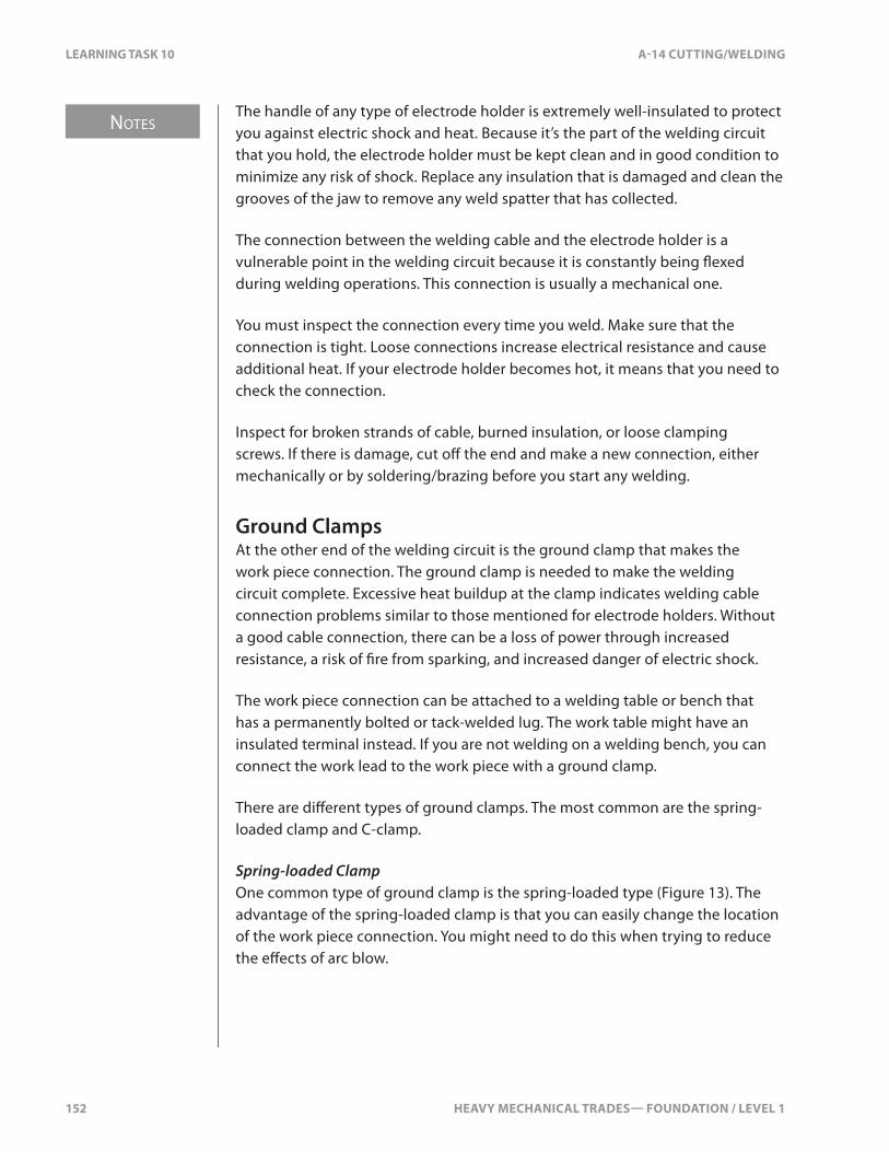
NOTES
152 HEAVY MECHANICAL TRADES— FOUNDATION / LEVEL 1
LEARNING TASK 10 A-14 CUTTING/WELDING
The handle of any type of electrode holder is extremely well-insulated to protect you against electric shock and heat. Because it’s the part of the welding circuit that you hold, the electrode holder must be kept clean and in good condition to minimize any risk of shock. Replace any insulation that is damaged and clean the grooves of the jaw to remove any weld spatter that has collected.
The connection between the welding cable and the electrode holder is a vulnerable point in the welding circuit because it is constantly being �exed during welding operations. This connection is usually a mechanical one.
You must inspect the connection every time you weld. Make sure that the connection is tight. Loose connections increase electrical resistance and cause additional heat. If your electrode holder becomes hot, it means that you need to check the connection.
Inspect for broken strands of cable, burned insulation, or loose clamping screws. If there is damage, cut o� the end and make a new connection, either mechanically or by soldering/brazing before you start any welding.
Ground ClampsAt the other end of the welding circuit is the ground clamp that makes the work piece connection. The ground clamp is needed to make the welding circuit complete. Excessive heat buildup at the clamp indicates welding cable connection problems similar to those mentioned for electrode holders. Without a good cable connection, there can be a loss of power through increased resistance, a risk of �re from sparking, and increased danger of electric shock.
The work piece connection can be attached to a welding table or bench that has a permanently bolted or tack-welded lug. The work table might have an insulated terminal instead. If you are not welding on a welding bench, you can connect the work lead to the work piece with a ground clamp.
There are di�erent types of ground clamps. The most common are the spring-loaded clamp and C-clamp.
Spring-loaded ClampOne common type of ground clamp is the spring-loaded type (Figure 13). The advantage of the spring-loaded clamp is that you can easily change the location of the work piece connection. You might need to do this when trying to reduce the e�ects of arc blow.
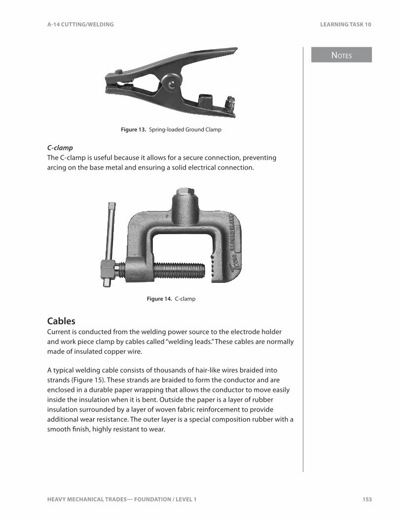
HEAVY MECHANICAL TRADES— FOUNDATION / LEVEL 1 153
NOTES
A-14 CUTTING/WELDING LEARNING TASK 10
Figure 13. Spring-loaded Ground Clamp
C-clampThe C-clamp is useful because it allows for a secure connection, preventing arcing on the base metal and ensuring a solid electrical connection.
Figure 14. C-clamp
CablesCurrent is conducted from the welding power source to the electrode holder and work piece clamp by cables called “welding leads.” These cables are normally made of insulated copper wire.
A typical welding cable consists of thousands of hair-like wires braided into strands (Figure 15). These strands are braided to form the conductor and are enclosed in a durable paper wrapping that allows the conductor to move easily inside the insulation when it is bent. Outside the paper is a layer of rubber insulation surrounded by a layer of woven fabric reinforcement to provide additional wear resistance. The outer layer is a special composition rubber with a smooth �nish, highly resistant to wear.
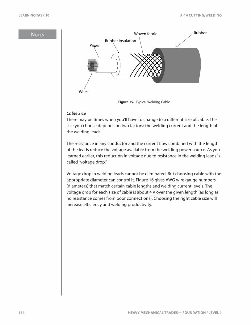
NOTES
154 HEAVY MECHANICAL TRADES— FOUNDATION / LEVEL 1
LEARNING TASK 10 A-14 CUTTING/WELDING
PaperRubber insulation
Woven fabric Rubber
Wires
Figure 15. Typical Welding Cable
Cable SizeThere may be times when you’ll have to change to a di�erent size of cable. The size you choose depends on two factors: the welding current and the length of the welding leads.
The resistance in any conductor and the current �ow combined with the length of the leads reduce the voltage available from the welding power source. As you learned earlier, this reduction in voltage due to resistance in the welding leads is called “voltage drop.”
Voltage drop in welding leads cannot be eliminated. But choosing cable with the appropriate diameter can control it. Figure 16 gives AWG wire gauge numbers (diameters) that match certain cable lengths and welding current levels. The voltage drop for each size of cable is about 4 V over the given length (as long as no resistance comes from poor connections). Choosing the right cable size will increase e�ciency and welding productivity.

HEAVY MECHANICAL TRADES— FOUNDATION / LEVEL 1 155
A-14 CUTTING/WELDING LEARNING TASK 10
Current capacity
100 A 150 A 200 A 250 A 300 A 350 A 400 A 450 A 500 ALe
ngth
of c
able
15 m/50 ft. 2 2 2 2 1 1/0 1/0 2/0 2/0
23 m/75 ft. 2 2 1 1/0 2/0 2/0 3/0 3/0 4/0
30 m/100 ft. 2 1 1/0 2/0 3/0 4/0 4/0
38 m/125 ft. 2 1/0 2/0 3/0 4/0
45 m/150 ft. 1 2/0 3/0 4/0
53 m/175 ft. 1/0 3/0 4/0
60 m/200 ft. 1/0 3/0 4/0
75 m/250 ft. 2/0 4/0
90 m/300 ft. 3/0
105 m/350 ft. 3/0
120 m/400 ft. 4/0
Figure 16. Recommended Copper Cable AWG Sizes for Arc Welding
MaintenanceMaintenance and care of welding leads is important. Follow these guidelines:
• Protect the leads against hot sparks and weld spatter from your work or that of nearby coworkers.
• Protect the leads from falling objects and cover them properly if vehicles will be driving over them.
• Prevent the leads from rubbing against sharp corners that could damage the insulation and create a �re or shock hazard.
• Use electrical tape to repair minor surface breaks in the welding leads. Replace any lead that appears to have serious damage.
Cable ConnectionsWelding leads have four possible connections:
• cable to electrode holder• cable to work piece or ground clamp• cable to cable• cable to welding power source terminals
No matter which type of terminal or type of attachment method you use, always make sure that all connections in the welding circuit are tight and clean before you start welding. If the connection requires protection by insulation, make sure this insulation is in good condition.
Cable to Electrode HolderThe connection of the welding cable to the electrode holder is usually a mechanical one (Figure 17). The bared end of the cable is wrapped with copper or brass shim stock. It is then �tted into the brass socket end of the electrode holder and secured with a set-screw. This connection will always be insulated, and usually the electrode holder handle provides this insulation.
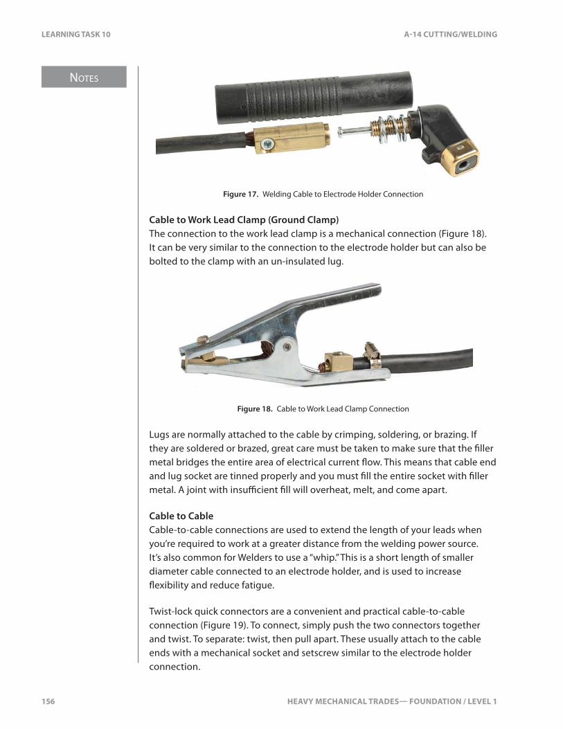
NOTES
156 HEAVY MECHANICAL TRADES— FOUNDATION / LEVEL 1
LEARNING TASK 10 A-14 CUTTING/WELDING
Figure 17. Welding Cable to Electrode Holder Connection
Cable to Work Lead Clamp (Ground Clamp)The connection to the work lead clamp is a mechanical connection (Figure 18). It can be very similar to the connection to the electrode holder but can also be bolted to the clamp with an un-insulated lug.
Figure 18. Cable to Work Lead Clamp Connection
Lugs are normally attached to the cable by crimping, soldering, or brazing. If they are soldered or brazed, great care must be taken to make sure that the �ller metal bridges the entire area of electrical current �ow. This means that cable end and lug socket are tinned properly and you must �ll the entire socket with �ller metal. A joint with insu�cient �ll will overheat, melt, and come apart.
Cable to CableCable-to-cable connections are used to extend the length of your leads when you’re required to work at a greater distance from the welding power source. It’s also common for Welders to use a “whip.” This is a short length of smaller diameter cable connected to an electrode holder, and is used to increase �exibility and reduce fatigue.
Twist-lock quick connectors are a convenient and practical cable-to-cable connection (Figure 19). To connect, simply push the two connectors together and twist. To separate: twist, then pull apart. These usually attach to the cable ends with a mechanical socket and setscrew similar to the electrode holder connection.

HEAVY MECHANICAL TRADES— FOUNDATION / LEVEL 1 157
NOTES
A-14 CUTTING/WELDING LEARNING TASK 10
Figure 19. Cable-to-cable Connections
Commercially produced permanent connectors are a convenient way of connecting welding leads to each other. The bared ends of the cables are inserted into the connector socket ends and either setscrews or crimping makes the connection. These connections must always be insulated.
Another way of making a cable-to-cable connection is by attaching a lug to each cable end, then bolting the two lugs together. This is a non-preferred method. You must always properly insulate these connections.
Cable to Welding Source TerminalsThere are two main types of connectors that are used between the welding cables and the terminals of the welding power source:
• The welding power source often has terminal connections requiring an un-insulated lug. These lugs are the same as the ones used for the cable to work lead clamp connection.
• Another common and convenient terminal connection is the built-in quick connector (Figure 20). The welding power source has a female quick connect receptacle, allowing it to receive any compatible male quick connect cable end. The quick connects may or may not be twist locks.
Figure 20. Welding Power Source Cable Connections

158 HEAVY MECHANICAL TRADES— FOUNDATION / LEVEL 1
SELF TEST 10 A-14 CUTTING/WELDING
SELF TEST 10
1. What does a transformer welding machine produce, without a recti�er?
a. AC current only
b. DC current only
c. both AC and DC current
d. high frequency AC current
2. What is the electrical term that identi�es an AC signal that is 1⁄60 of a second?
a. frequency
b. three phase
c. one cycle
d. 60 hertz
3. What polarity is the welding electrode with an AC signal?
a. electrode .5 cycle negative, .5 cycle positive
b. electrode negative
c. electrode positive
d. electrode positive and negative
4. The duty cycle is a way of rating a welding power source. What time period is the duty cycle rated at?
a. 5 minutes
b. 10 minutes
c. 15 minutes
d. 20 minutes
HEAVY MECHANICAL TRADES— FOUNDATION / LEVEL 1 159
NOTES
A-14 CUTTING/WELDING LEARNING TASK 11
LEARNING TASK 11
Identify Mild Steel Electrodes for Shielded Metal Arc Welding
Operation of Common Electrodes for SMAWThe basic function of the welding electrode in the arc welding circuit is to carry the current that generates the arc. This means that an electrode must be a good conductor of electricity. In the SMAW process, the electrode must also melt and fuse with the base metal in order to create an e�ective weld (Figure 1). For this reason, electrodes are manufactured with a variety of di�erent cores that are compatible with di�erent base metals.
In the SMAW process, electrodes have another important function: to help control the following aspects of the welding process:
• rate of melting• amount of deposition• creation of slag• stability and direction of the arc• depth of penetration• rate at which the molten weld metal solidi�es (weld pool freezes)• addition of alloys to the weld metal• provision of gases to protect or shield the molten weld pool
To ful�ll these functions, the composition of arc welding electrodes are more complex than the �ller rods used in oxy-fuel and gas tungsten arc welding.
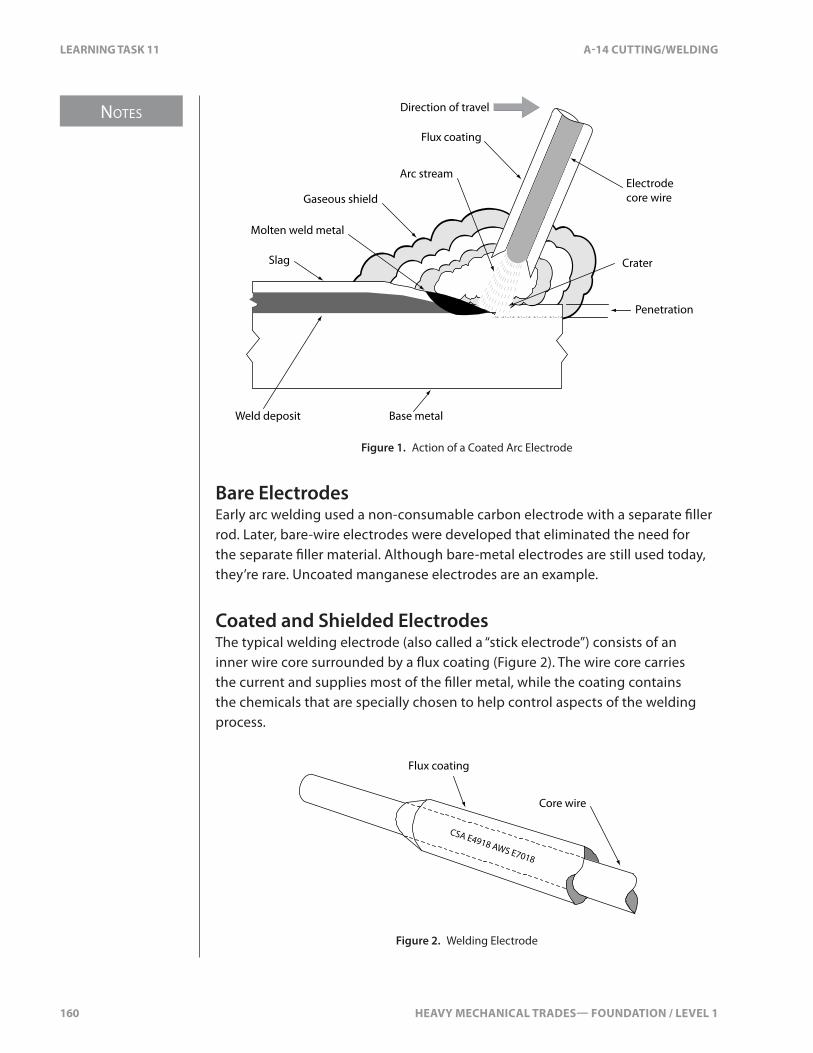
NOTES
160 HEAVY MECHANICAL TRADES— FOUNDATION / LEVEL 1
LEARNING TASK 11 A-14 CUTTING/WELDING
Direction of travel
Flux coating
Arc stream
Gaseous shield
Molten weld metal
Slag
Electrode core wire
Crater
Penetration
Base metalWeld deposit
Figure 1. Action of a Coated Arc Electrode
Bare ElectrodesEarly arc welding used a non-consumable carbon electrode with a separate �ller rod. Later, bare-wire electrodes were developed that eliminated the need for the separate �ller material. Although bare-metal electrodes are still used today, they’re rare. Uncoated manganese electrodes are an example.
Coated and Shielded ElectrodesThe typical welding electrode (also called a “stick electrode”) consists of an inner wire core surrounded by a �ux coating (Figure 2). The wire core carries the current and supplies most of the �ller metal, while the coating contains the chemicals that are specially chosen to help control aspects of the welding process.
Flux coating
Core wire
CSA E4918 AWS E7018
Figure 2. Welding Electrode
HEAVY MECHANICAL TRADES— FOUNDATION / LEVEL 1 161
NOTES
A-14 CUTTING/WELDING LEARNING TASK 11
Functions of Flux CoatingsThe �ux coating on the electrode performs six functions:
• It forms a gaseous shield to keep oxygen and nitrogen away from the weld pool.
• It aids and controls the nature of the electric arc stream of plasma and metal particles.
• It cleans the weld pool by �oating out impurities and scavenging for trace amounts of oxygen.
• It adds alloying elements and in some cases, �ller material to the weld metal.
• It forms a cover that shapes the cooling weld metal and protects it from oxidation.
• It forms a cover of slag over the cooling weld bead to reduce the cooling rate.
Size of the ElectrodesSizes of SMAW electrodes are measured as the diameter of the inner core wire, excluding the �ux coating. Following are standard SMAW electrode sizes:
• 1.6 mm (1⁄16 in.)• 2.0 mm (5⁄64 in.)• 2.5 mm (3⁄32 in.)• 3.2 mm (1⁄8 in.)• 4.0 mm (5⁄32 in.)• 5.0 mm (3⁄16 in.)• 5.6 mm (7⁄32 in.)• 6.4 mm (1⁄4 in.)• 8.0 mm (5⁄16 in.)
Lengths range from 225–1000 mm (9–36 in.). The most common length is 350 mm (14 in.). The coatings are designated as light, medium, or heavy.
Types of ElectrodesSMAW electrodes come in several types, depending on the composition of their coatings. The ingredients in the electrode coating control four important features:
• the amount of �ller metal produced• the speed at which �ller metal is deposited• the speed with which the molten weld metal solidi�es (weld
pool freezes)• the inclusion of hydrogen in the weld deposit
NOTES
162 HEAVY MECHANICAL TRADES— FOUNDATION / LEVEL 1
LEARNING TASK 11 A-14 CUTTING/WELDING
Fast-�llFast-�ll electrodes deposit substantial amounts of �ller metal at a fast rate. Electrodes used for production work frequently have this characteristic. They’re usually heavy-coated and often contain substantial amounts of iron powder to add �ller metal.
Fast-freezeFast-freeze electrodes deposit a weld bead with the ability to solidify or freeze quickly. They generally operate with an arc that penetrates deeply but produces little slag. These characteristics make them suitable for welding in the vertical and overhead positions where the e�ects of gravity need to be counteracted.
Fill-freezeFill-freeze or fast-follow electrodes allow for higher travel speeds with consistent bead formation. They deposit thin, narrow stringer beads with shallow penetration. Their main use is for welds that require little �ller material, as on light-gauge sheet metal. As the name suggests, �ll-freeze electrodes combine both fast-�ll and fast-freeze characteristics.
Low-hydrogenAnother special group of electrodes is the low-hydrogen, or basic, electrodes. Hydrogen can be harmful to the metallic properties of weld metal, especially to welds on high-strength low-alloy, medium-carbon, high-carbon, and high-sulphur steels. The transfer of hydrogen from the electrode to the weld deposit can lead to hydrogen being trapped in the weld metal. This can lead to cracking, which often occurs many hours after the weld is completed.
Submersing weldments in glycerin shortly after the welds are completed shows that hydrogen can be trapped in the weld metal (Figure 3). The image on the left shows the surface of a weld bead, while the image on the right shows a weld cut on the diagonal. In both pictures, the hydrogen trapped in the weld metal can be seen leaving the weld bead.

HEAVY MECHANICAL TRADES— FOUNDATION / LEVEL 1 163
NOTES
A-14 CUTTING/WELDING LEARNING TASK 11
Figure 3. Weldments Submerged in Glycerin
These pictures clearly show that hydrogen has been trapped in the weld metal. Hydrogen trapped in weld metal can create internal stresses that can lead to underbead cracking, even in low-carbon steels. Hydrogen is a serious concern when welding high-strength low-alloy, medium-carbon, high-carbon, and high-sulphur steels.
To protect sensitive base metals from the presence of hydrogen, low-hydrogen electrodes are manufactured with electrode coatings that do not have organic substances containing hydrogen.
Composition of SMAW Electrode CoatingsSMAW electrode coatings can contain many di�erent chemicals, minerals, and ores. Di�erent combinations of these materials serve speci�c purposes. This generally restricts each electrode type to a particular situation, such as welding position, welding current, or current setting.
NOTES
164 HEAVY MECHANICAL TRADES— FOUNDATION / LEVEL 1
LEARNING TASK 11 A-14 CUTTING/WELDING
The main chemical ingredients used in di�erent combinations to produce electrodes of di�erent types are:
• cellulose• rutile• china clay, silica, and mica• potassium• ferro-manganese• iron oxide (magnetite, hematite)• iron powder• sodium silicate
CelluloseCellulose is made from wood pulp. It helps form the inverted cup-type shield at the electrode tip that gives direction to the shielding gases and to the arc stream. Cellulose also produces the shielding gases. As the cellulose is consumed, it forms a gaseous envelope of carbon dioxide and water vapour that excludes oxygen and nitrogen. Sodium or potassium is added to these coatings to stabilize the arc.
Rutile“Rutile” is another term for titanium dioxide. It makes the arc smooth and stable and forms a hard, black slag that gives a smooth �nish to the weld. Like cellulose, rutile is frequently combined with sodium or potassium.
China Clay, Silica, and MicaChina clay, silica, and mica are generally used in electrode coatings to provide slag volume. In varying quantities, they’re also important in controlling the viscosity and the surface tension of the slag as well as the rate at which the slag freezes.
PotassiumIn electrode coatings, potassium is used as an arc stabilizer and as an ionizer. As an ionizer, it alters the electrical characteristics of the arc and helps ease and stabilize the �ow of current. In addition to its use in compounds with cellulose and rutile, potassium is combined with feldspar or with titanium. It’s commonly used in AC electrodes to promote a stable arc.
Ferro-manganeseFerro-manganese is an alloy containing about 80% manganese. When used in electrode coatings, it helps remove oxygen from the arc by combining with the oxygen to form an oxide. The oxide then forms part of the slag.
HEAVY MECHANICAL TRADES— FOUNDATION / LEVEL 1 165
NOTES
A-14 CUTTING/WELDING LEARNING TASK 11
Iron Oxide (Magnetite, Hematite)Magnetite and hematite are ores that produce a heavy slag. Their particular property is that they can dissolve large quantities of oxides that might be formed during the welding operation. Although the resulting weld is lower in tensile strength, the appearance of the weld is smooth.
Iron PowderIron powder can make up 10–60% of an electrode coating. It creates a heavier coating that adds to the �ller material produced by the electrode wire. It also allows for the use of higher welding current. This increases the rate of deposition of the weld. Iron powder also improves the appearance of the �nished weld, makes the weld more ductile, and makes slag removal easier.
Using iron powder in the electrode also helps reduce arc instability during AC welding.
Sodium SilicateSodium silicate, more commonly known as “water glass,” is a heavy liquid, quite viscous and sticky. It is used to bind together the various ingredients of electrode coatings so that they can coat the core wire.
Metal Transfer with SMAW ElectrodesIn the SMAW process, the heat of the arc melts the core wire of the coated electrode and this metal is transferred across the arc gap to the base metal. At the same time, the heat of the arc melts the base metal. The molten metal from the electrode combines with the molten base metal in the weld pool (or puddle) to form the weld metal.
There are a number of theories to explain how the molten metal in the electrode is carried across the arc gap to the work piece. None of these explanations gives a complete picture. What is clear is that this metal transfer always takes place, whether electrode positive or electrode negative. It also occurs in opposition to the force of gravity when you weld in the overhead position.
GravityGravity is clearly a factor in metal transfer from electrode to weld pool. When you’re welding in the �at position, gravity helps metal transfer. But when you’re welding in the overhead, vertical, or horizontal positions, gravity has an adverse e�ect. Using smaller diameter electrodes helps minimize this by reducing the loss of weld metal.
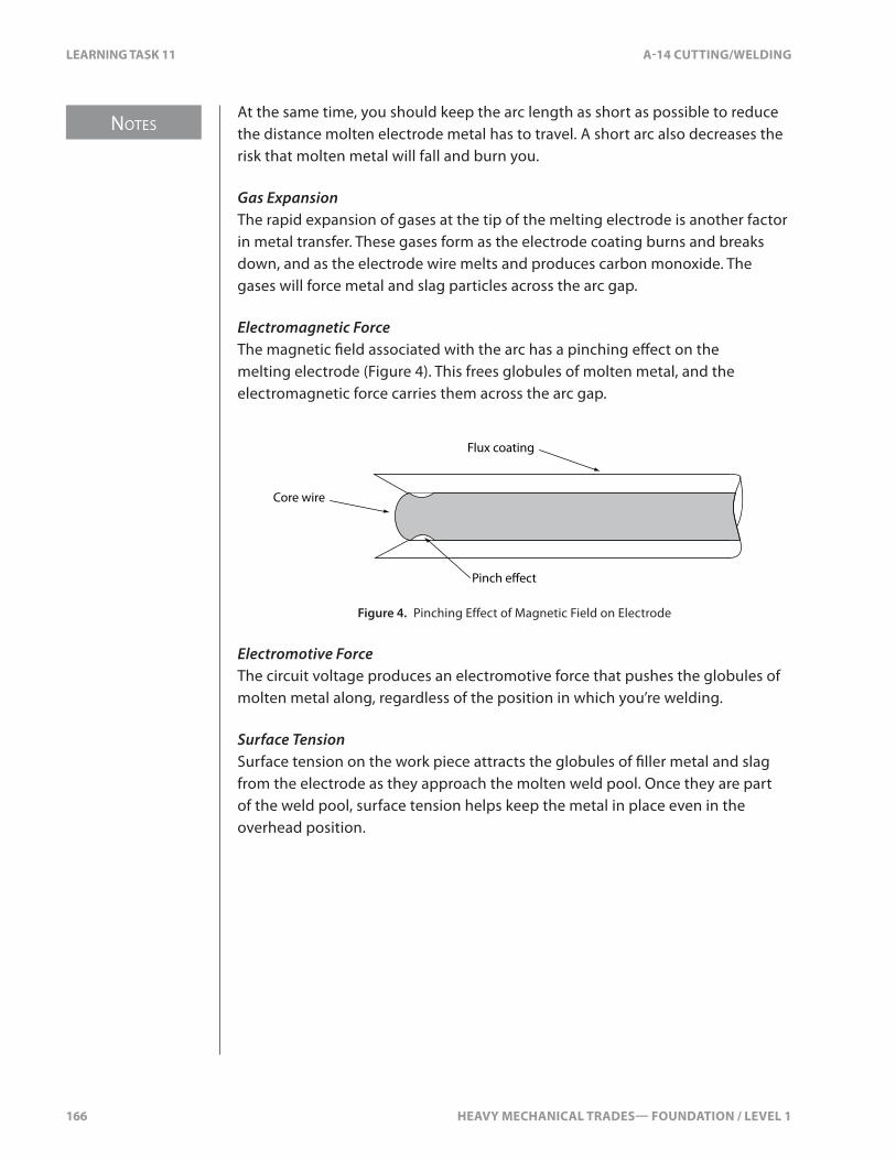
NOTES
166 HEAVY MECHANICAL TRADES— FOUNDATION / LEVEL 1
LEARNING TASK 11 A-14 CUTTING/WELDING
At the same time, you should keep the arc length as short as possible to reduce the distance molten electrode metal has to travel. A short arc also decreases the risk that molten metal will fall and burn you.
Gas ExpansionThe rapid expansion of gases at the tip of the melting electrode is another factor in metal transfer. These gases form as the electrode coating burns and breaks down, and as the electrode wire melts and produces carbon monoxide. The gases will force metal and slag particles across the arc gap.
Electromagnetic ForceThe magnetic �eld associated with the arc has a pinching e�ect on the melting electrode (Figure 4). This frees globules of molten metal, and the electromagnetic force carries them across the arc gap.
Pinch e�ect
Flux coating
Core wire
Figure 4. Pinching Effect of Magnetic Field on Electrode
Electromotive ForceThe circuit voltage produces an electromotive force that pushes the globules of molten metal along, regardless of the position in which you’re welding.
Surface TensionSurface tension on the work piece attracts the globules of �ller metal and slag from the electrode as they approach the molten weld pool. Once they are part of the weld pool, surface tension helps keep the metal in place even in the overhead position.

HEAVY MECHANICAL TRADES— FOUNDATION / LEVEL 1 167
NOTES
A-14 CUTTING/WELDING LEARNING TASK 11
Classi�cations of Low-carbon Steel ElectrodesStandards of Coated Electrode ManufactureAdvances in welding technology have resulted in the development of a wide variety of electrodes to meet di�erent welding requirements. This has made it necessary to have a method of electrode classi�cation that ensures uniformity of manufacture and performance.
The systems developed use a letter and number code to indicate the content and performance speci�cations of an electrode. Manufacturers must print the appropriate code number on the coating of every electrode (Figure 5). In North America, three basic classi�cation systems are used. These are the ASME, CSA, and AWS systems.
CSA E4918 AWS E7018
CSA E4310 AWS E6010
Figure 5. Electrode with Code Marking
The most general classi�cation system is that developed by the American Society of Mechanical Engineers (ASME). It uses F numbers to group electrodes according to their �ller metal and coating type. This system is important in the complete de�nition of the speci�cations of any electrode, but it is not the system that Welders normally use to identify individual electrodes.
The classi�cation systems Welders commonly use, are those developed by the Canadian Standards Association (CSA) in conjunction with the Canadian Welding Bureau (CWB) and the American Welding Society (AWS). These two systems both use a letter/number code to convey similar information. The main di�erence between the systems is that the CSA system uses metric measurement while the AWS system uses imperial measurement.
All low-carbon steel electrodes manufactured or used in Canada must meet the standards published by the CSA in its Bulletin W48-06 and certi�ed by the CWB. These standards are almost identical to those published by the AWS in its Bulletin A5.1.

NOTES
168 HEAVY MECHANICAL TRADES— FOUNDATION / LEVEL 1
LEARNING TASK 11 A-14 CUTTING/WELDING
CSA and AWS DesignationsThere are over 150 di�erent electrodes available in the area of low-carbon, low-alloy, stainless, and specialty steels. To choose the most appropriate electrode for a particular job, you must understand the identi�cation information given by the code numbers in both the CSA and the AWS systems.
The code number provides the following information:
• if the �ller metal rod is to be used for electric arc welding or gas welding
• the tensile strength of the welds produced with that �ller metal rod• the welding position recommended for use with that �ller metal rod• the kind of current supply and circuit setup to be used• the composition of the �ller metal rod coating
Under the CSA system that’s used in Canada, an identi�cation number consists of a letter or letters followed by four digits (Figures 6–8).
E 43 1 0
designates electric welding
designates tensile strength in tens of megapascals (MPa)
designates welding position
designates composition of coating and current requirements
Figure 6. E4310 Electrode
2nd to last digit Position
1 all positions except vertical down*
2 �at and horizontal �llet
3 �at position only**
4 vertical down
* Vertical down restrictions may vary between certifying authorities.
** Not a CSA or AWS designation.
Figure 7. Weld Positions Indicated by the Second Last Digit
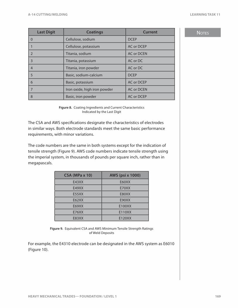
HEAVY MECHANICAL TRADES— FOUNDATION / LEVEL 1 169
NOTES
A-14 CUTTING/WELDING LEARNING TASK 11
Last Digit Coatings Current
0 Cellulose, sodium DCEP
1 Cellulose, potassium AC or DCEP
2 Titania, sodium AC or DCEN
3 Titania, potassium AC or DC
4 Titania, iron powder AC or DC
5 Basic, sodium-calcium DCEP
6 Basic, potassium AC or DCEP
7 Iron oxide, high iron powder AC or DCEN
8 Basic, iron powder AC or DCEP
Figure 8. Coating Ingredients and Current Characteristics Indicated by the Last Digit
The CSA and AWS speci�cations designate the characteristics of electrodes in similar ways. Both electrode standards meet the same basic performance requirements, with minor variations.
The code numbers are the same in both systems except for the indication of tensile strength (Figure 9). AWS code numbers indicate tensile strength using the imperial system, in thousands of pounds per square inch, rather than in megapascals.
CSA (MPa x 10) AWS (psi x 1000)
E43XX E60XX
E49XX E70XX
E55XX E80XX
E62XX E90XX
E69XX E100XX
E76XX E110XX
E83XX E120XX
Figure 9. Equivalent CSA and AWS Minimum Tensile Strength Ratings of Weld Deposits
For example, the E4310 electrode can be designated in the AWS system as E6010 (Figure 10).
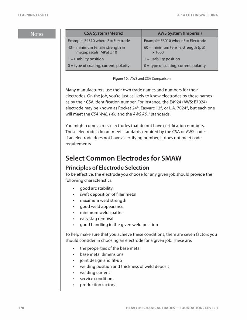
NOTES
170 HEAVY MECHANICAL TRADES— FOUNDATION / LEVEL 1
LEARNING TASK 11 A-14 CUTTING/WELDING
CSA System (Metric) AWS System (Imperial)
Example: E4310 where E = Electrode
43 = minimum tensile strength in megapascals (MPa) x 10
1 = usability position
0 = type of coating, current, polarity
Example: E6010 where E = Electrode
60 = minimum tensile strength (psi) x 1000
1 = usability position
0 = type of coating, current, polarity
Figure 10. AWS and CSA Comparison
Many manufacturers use their own trade names and numbers for their electrodes. On the job, you’re just as likely to know electrodes by these names as by their CSA identi�cation number. For instance, the E4924 (AWS: E7024) electrode may be known as Rocket 24®, Easyarc 12®, or L.A. 7024®, but each one will meet the CSA W48.1-06 and the AWS A5.1 standards.
You might come across electrodes that do not have certi�cation numbers. These electrodes do not meet standards required by the CSA or AWS codes. If an electrode does not have a certifying number, it does not meet code requirements.
Select Common Electrodes for SMAWPrinciples of Electrode SelectionTo be e�ective, the electrode you choose for any given job should provide the following characteristics:
• good arc stability• swift deposition of �ller metal• maximum weld strength• good weld appearance• minimum weld spatter• easy slag removal• good handling in the given weld position
To help make sure that you achieve these conditions, there are seven factors you should consider in choosing an electrode for a given job. These are:
• the properties of the base metal• base metal dimensions• joint design and �t-up• welding position and thickness of weld deposit• welding current• service conditions• production factors
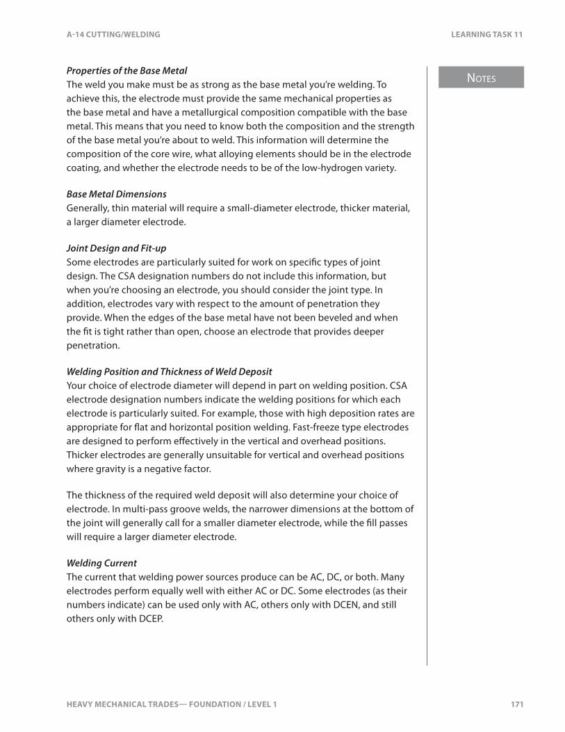
HEAVY MECHANICAL TRADES— FOUNDATION / LEVEL 1 171
NOTES
A-14 CUTTING/WELDING LEARNING TASK 11
Properties of the Base MetalThe weld you make must be as strong as the base metal you’re welding. To achieve this, the electrode must provide the same mechanical properties as the base metal and have a metallurgical composition compatible with the base metal. This means that you need to know both the composition and the strength of the base metal you’re about to weld. This information will determine the composition of the core wire, what alloying elements should be in the electrode coating, and whether the electrode needs to be of the low-hydrogen variety.
Base Metal DimensionsGenerally, thin material will require a small-diameter electrode, thicker material, a larger diameter electrode.
Joint Design and Fit-upSome electrodes are particularly suited for work on speci�c types of joint design. The CSA designation numbers do not include this information, but when you’re choosing an electrode, you should consider the joint type. In addition, electrodes vary with respect to the amount of penetration they provide. When the edges of the base metal have not been beveled and when the �t is tight rather than open, choose an electrode that provides deeper penetration.
Welding Position and Thickness of Weld DepositYour choice of electrode diameter will depend in part on welding position. CSA electrode designation numbers indicate the welding positions for which each electrode is particularly suited. For example, those with high deposition rates are appropriate for �at and horizontal position welding. Fast-freeze type electrodes are designed to perform e�ectively in the vertical and overhead positions. Thicker electrodes are generally unsuitable for vertical and overhead positions where gravity is a negative factor.
The thickness of the required weld deposit will also determine your choice of electrode. In multi-pass groove welds, the narrower dimensions at the bottom of the joint will generally call for a smaller diameter electrode, while the �ll passes will require a larger diameter electrode.
Welding CurrentThe current that welding power sources produce can be AC, DC, or both. Many electrodes perform equally well with either AC or DC. Some electrodes (as their numbers indicate) can be used only with AC, others only with DCEN, and still others only with DCEP.
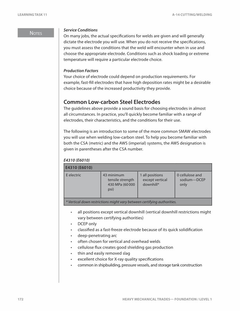
NOTES
172 HEAVY MECHANICAL TRADES— FOUNDATION / LEVEL 1
LEARNING TASK 11 A-14 CUTTING/WELDING
Service ConditionsOn many jobs, the actual speci�cations for welds are given and will generally dictate the electrode you will use. When you do not receive the speci�cations, you must assess the conditions that the weld will encounter when in use and choose the appropriate electrode. Conditions such as shock loading or extreme temperature will require a particular electrode choice.
Production FactorsYour choice of electrode could depend on production requirements. For example, fast-�ll electrodes that have high deposition rates might be a desirable choice because of the increased productivity they provide.
Common Low-carbon Steel ElectrodesThe guidelines above provide a sound basis for choosing electrodes in almost all circumstances. In practice, you’ll quickly become familiar with a range of electrodes, their characteristics, and the conditions for their use.
The following is an introduction to some of the more common SMAW electrodes you will use when welding low-carbon steel. To help you become familiar with both the CSA (metric) and the AWS (imperial) systems, the AWS designation is given in parentheses after the CSA number.
E4310 (E6010)
E4310 (E6010)
E electric 43 minimum tensile strength 430 MPa (60 000 psi)
1 all positions except vertical downhill*
0 cellulose and sodium—DCEP only
* Vertical down restrictions might vary between certifying authorities.
• all positions except vertical downhill (vertical downhill restrictions might vary between certifying authorities)
• DCEP only• classi�ed as a fast-freeze electrode because of its quick solidi�cation• deep-penetrating arc• often chosen for vertical and overhead welds• cellulose �ux creates good shielding gas production• thin and easily removed slag• excellent choice for X-ray quality speci�cations• common in shipbuilding, pressure vessels, and storage tank construction

HEAVY MECHANICAL TRADES— FOUNDATION / LEVEL 1 173
NOTES
A-14 CUTTING/WELDING LEARNING TASK 11
E4311 (E6011)
E4311 (E6011)
E electric 43 minimum tensile strength 430 MPa (60 000 psi)
1 all positions except vertical downhill*
1 cellulose and potassium—AC or DCEP
* Vertical down restrictions might vary between certifying authorities.
• all positions except vertical downhill (vertical downhill restrictions might vary between certifying authorities)
• AC, DCEP• classi�ed as a fast-freeze electrode [AC version of E4310 (E6010)]• deep-penetrating arc• cellulose �ux provides good shielding gas production• thin and easily removed slag• excellent choice for X-ray quality speci�cations• common in shipbuilding, pressure vessels, and storage tank construction
E4313 (E6013)
E4313 (E6013)
E electric 43 minimum tensile strength 430 MPa (60 000 psi)
1 all positions 3 titania (rutile) potassium—AC or DC
• all-position electrode• AC, DC (either polarity, DCEN preferred)• classi�ed as �ll-freeze (fast-follow)• medium penetration rutile electrode coating• medium slag coating that gives a good weld appearance and �akes o�
easily• popular for vertical down on light gauge and for use on simple AC power
sources
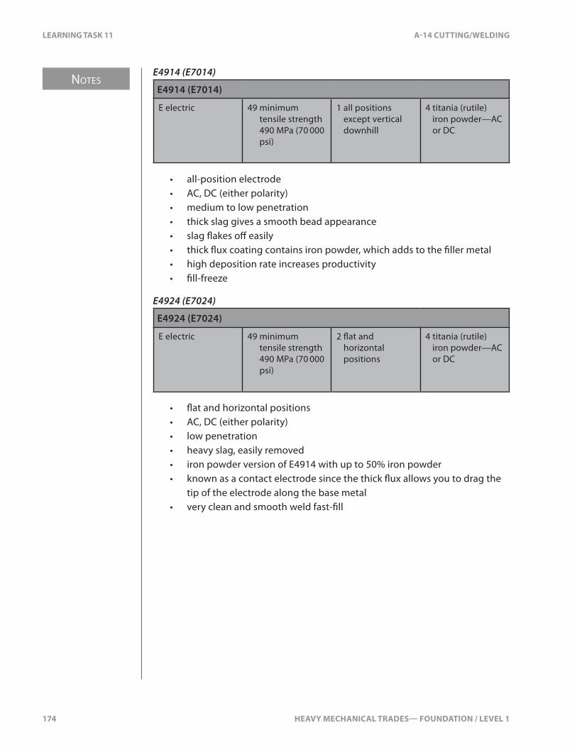
NOTES
174 HEAVY MECHANICAL TRADES— FOUNDATION / LEVEL 1
LEARNING TASK 11 A-14 CUTTING/WELDING
E4914 (E7014)
E4914 (E7014)
E electric 49 minimum tensile strength 490 MPa (70 000 psi)
1 all positions except vertical downhill
4 titania (rutile) iron powder—AC or DC
• all-position electrode• AC, DC (either polarity)• medium to low penetration• thick slag gives a smooth bead appearance• slag �akes o� easily• thick �ux coating contains iron powder, which adds to the �ller metal• high deposition rate increases productivity• �ll-freeze
E4924 (E7024)
E4924 (E7024)
E electric 49 minimum tensile strength 490 MPa (70 000 psi)
2 �at and horizontal positions
4 titania (rutile) iron powder—AC or DC
• �at and horizontal positions• AC, DC (either polarity)• low penetration• heavy slag, easily removed• iron powder version of E4914 with up to 50% iron powder• known as a contact electrode since the thick �ux allows you to drag the
tip of the electrode along the base metal• very clean and smooth weld fast-�ll

HEAVY MECHANICAL TRADES— FOUNDATION / LEVEL 1 175
NOTES
A-14 CUTTING/WELDING LEARNING TASK 11
E4918 (E7018)
E4918 (E7018)
E electric 49 minimum tensile strength 490 MPa (70 000 psi)
1 all positions except vertical downhill
8 low hydrogen, potassium, iron powder—AC or DCEP
• all positions except vertical downhill• low hydrogen (basic coating)• designed for low-alloy steels and unknown alloys that are prone to
underbead cracking from hydrogen entrapment• 25–40% iron powder in �ux• arc length must be kept short to prevent porosity• designator after the number indicates the maximum level of hydrogen
(e.g., H2, H4, H16)
Electrodes for HardfacingElectrodes for hardfacing are applied to surfaces that require a hard skin. The hardness of the skin depends on the alloys in the electrode. There’s no exact standard for hardfacing welding electrodes. Each manufacturer produces di�erent formulations and supplies data on the weld beads produced and their expected hardness and toughness.
The various products create surfaces that range from very soft, all the way up to glass hard. When you apply a hardfacing weld, it’s important to understand the application. If the weld is too hard and brittle, it will fracture and break away from the surface (spalling). If it’s too soft, it will be quickly worn away.
Hardfacing welding electrodes are based on several alloys made from carbon, cobalt, nickel, chromium, tungsten, and manganese. They can be loosely categorized as:
• tungsten carbides• chromium carbides• semi-austenitic steels• austenitic manganese steels• austenitic stainless steels• martenisitic stainless steels• carbon steel alloys
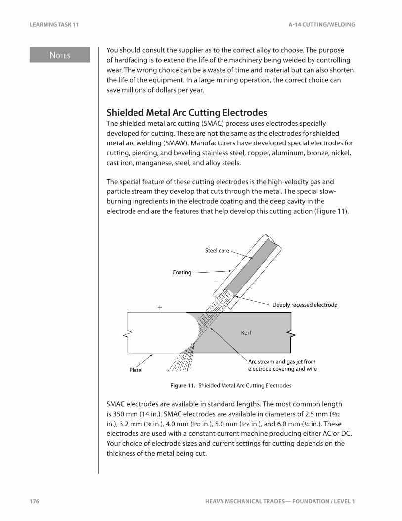
NOTES
176 HEAVY MECHANICAL TRADES— FOUNDATION / LEVEL 1
LEARNING TASK 11 A-14 CUTTING/WELDING
You should consult the supplier as to the correct alloy to choose. The purpose of hardfacing is to extend the life of the machinery being welded by controlling wear. The wrong choice can be a waste of time and material but can also shorten the life of the equipment. In a large mining operation, the correct choice can save millions of dollars per year.
Shielded Metal Arc Cutting ElectrodesThe shielded metal arc cutting (SMAC) process uses electrodes specially developed for cutting. These are not the same as the electrodes for shielded metal arc welding (SMAW). Manufacturers have developed special electrodes for cutting, piercing, and beveling stainless steel, copper, aluminum, bronze, nickel, cast iron, manganese, steel, and alloy steels.
The special feature of these cutting electrodes is the high-velocity gas and particle stream they develop that cuts through the metal. The special slow-burning ingredients in the electrode coating and the deep cavity in the electrode end are the features that help develop this cutting action (Figure 11).
Kerf
PlateArc stream and gas jet from electrode covering and wire
Deeply recessed electrode
Steel core
Coating
+
–
Figure 11. Shielded Metal Arc Cutting Electrodes
SMAC electrodes are available in standard lengths. The most common length is 350 mm (14 in.). SMAC electrodes are available in diameters of 2.5 mm (3⁄32 in.), 3.2 mm (1⁄8 in.), 4.0 mm (5⁄32 in.), 5.0 mm (3⁄16 in.), and 6.0 mm (1⁄4 in.). These electrodes are used with a constant current machine producing either AC or DC. Your choice of electrode sizes and current settings for cutting depends on the thickness of the metal being cut.
HEAVY MECHANICAL TRADES— FOUNDATION / LEVEL 1 177
NOTES
A-14 CUTTING/WELDING LEARNING TASK 11
Techniques used for cutting include the use of a very short arc. The electrode can be dragged across the metal without any danger of it shorting out because of the heavy coating and the recessed electrode wire.
Cutting with Standard SMAW ElectrodesRegular shielded metal arc welding electrodes can also be used for cutting low-carbon steel. However, this will require a higher current than a SMAC electrode would. SMAW electrodes used for cutting will last a little longer if they are soaked in water for a few minutes before use. The absorbed moisture slows down the vapourizing of the coating and helps produce a deeper cup at the end of the electrode. This increased cavity creates a more forceful jet action.
Never use a water-soaked electrode for welding. The absorbed moisture will cause hydrogen to be trapped in the weld.
Correct Handling and Storage of Common SMAW ElectrodesSMAW electrodes are both fragile and expensive. You must handle electrodes carefully at all times.
Handling of Electrodes Before and After UseElectrodes must be handled with great care to avoid breaking or cracking the coating. An electrode with a damaged coating will usually perform poorly. If pieces of the coating are actually missing, the result will be poor weld appearance and porosity in the weld.
Because electrodes with very di�erent properties can look the same, correct handling of electrodes also includes marking them accurately after the package has been opened. It’s equally important to collect and clearly mark unused electrodes that are being returned to storage. Do not risk producing a weld that does not meet speci�cations just because you used the wrong electrode. An electrode that is not clearly identi�ed should be considered unusable.
Storage of ElectrodesThe main requirement for storing electrodes is to keep them dry. Not only are electrode coatings fragile, but their composition allows them to pick up moisture from the air.
NOTES
178 HEAVY MECHANICAL TRADES— FOUNDATION / LEVEL 1
LEARNING TASK 11 A-14 CUTTING/WELDING
Prolonged exposure to moisture can cause the coating to disintegrate. Even if the disintegration is not obvious, the heat of the arc will actually blow away portions of the coating. In either case, the electrode becomes useless and must be discarded.
Any moisture that an electrode absorbs contains hydrogen. During welding, some of this hydrogen is transferred to the weld metal. This can lead to a number of problems with the weld. Depending on the composition of the base metal, these problems can include embrittlement, porosity, cracking of the weld, and a rough weld appearance. In addition, welding with a moist electrode increases the arc voltage, increases weld spatter, and makes slag removal di�cult.
Some electrodes (such as mineral-coated ones) are more prone to absorbing moisture than others. The length of time electrodes can be exposed to the atmosphere varies from 30 minutes to four hours or longer, depending on the relative humidity of the atmosphere. For example, the maximum exposure time for low-hydrogen electrodes is between two and four hours, depending on the relative humidity. A perfectly dry, low-hydrogen electrode is essential to produce a satisfactory weld. Low-hydrogen electrodes must be thrown away if they have been directly exposed to water.
With all electrodes, it’s impossible to tell simply by looking at them whether they have absorbed dangerous amounts of moisture. To protect electrodes from moisture, manufacturers ship them in airtight containers. On the job site, electrodes are stored in sealed portable electrode containers.
Electrode OvensSome electrodes can be safely stored at normal room conditions if the temperature and relative humidity do not go above certain normal tolerances. For other types of electrodes, electrode ovens are used to guarantee a humidity-controlled environment for storage.
Ovens are essential for the more sensitive low-hydrogen and hardfacing electrodes and for special-alloy electrodes such as stainless steel, brass, bronze, aluminum, Inconel, and Monel.
Welding shops often have large electrode ovens that are capable of holding several hundred kilograms of electrodes. There are also smaller �eld ovens that can be connected to an auxiliary power supply.
Ovens can sometimes be used to re-bake electrodes that have been exposed to moisture in order to make the usable. Electrode manufacturers and suppliers provide information on storage and re-baking conditions for their electrodes and, if available, these recommendations should be followed (Figure 12).

HEAVY MECHANICAL TRADES— FOUNDATION / LEVEL 1 179
NOTES
A-14 CUTTING/WELDING LEARNING TASK 11
CSA # AWS # Normal room Holding ovens Re-bake
E4310
E4311
E6010
E6011
25ºC ± 10ºC
(80ºF ± 20ºF)
(50–70% relative humidity)
Consult supplier for storage and re-bake conditions.
E4313 E6013 25ºC ± 10ºC
(80ºF ± 20ºF)
10ºC to 20ºC (20ºF to 40ºF)
above ambient temperature
135ºC ± 15ºC
E4914 E7014 50% max. relative humidity
1 hr. at temp.
E4924 E7024
E4918 E7018 25ºC to 140ºC (50ºF to 250ºF) above ambient temperature
350ºC ± 25ºC
(650ºF ± 50ºF) for 1 hr.
Stainless steel
Hardfacing
High-strength alloy
103ºC to 127ºC
(215ºF to 260ºF)
179ºC to 315ºC
(350ºF to 600ºF)
check manufacturer for detailed procedure
Figure 12. Electrode Storage Conditions
180 HEAVY MECHANICAL TRADES— FOUNDATION / LEVEL 1
SELF TEST 11 A-14 CUTTING/WELDING
SELF TEST 11
1. What force is responsible for transferring molten particles of metal across the arc, by means of a pinching e�ect?
a. gravity
b. electromagnetism
c. gas expansion
d. surface tension
2. What does the electrode code E4918 (E7018) stand for?
a. 49000 psi/�at and horizontal position/ cellulose and potassium
b. 70000 psi/ all positions/ cellulose and potassium
c. 70000 psi/ all positions/ low hydrogen
d. 49000 psi/ all positions/ low hydrogen
3. What does the number “8” refer to when using an E7018 welding rod?
a. tensile strength
b. position
c. composition of coating and current requirements
d. heat range

HEAVY MECHANICAL TRADES— FOUNDATION / LEVEL 1 181
NOTES
A-14 CUTTING/WELDING LEARNING TASK 12
LEARNING TASK 12
Weld Mild Steel with Shielded Metal Arc Welding
Set-up ProceduresSet-up procedures will vary depending on the location of the weld and equipment. You may be working on a bench in a shop environment or on a machine on a job site. Each of these requires di�erent set-up and safety concerns.
Shop EnvironmentMost shops will have a welding area close to the repair shop, but some shops will use the repair shop area for both welding and repairs. There are several aspects of any welding area that deserve your attention:
• proper fume ventilation• screens for visual protection against �ashes• noise protection when welding, grinding, and air-arcing• air particle contamination• �re hazards• �re safety equipment• proper egress
Once you’ve met all the concerns, you can move your cables and prepare for the weld. You’ll set-up the machine and perform a test pass before welding the project. You should always be aware of your environment and remember that other people may be working in the same area.
Job Site EnvironmentWhen at a job site, you will often need to work outdoors. This presents a di�erent set of concerns:
• brush and grass �re• �re safety equipment• screens for visual protection against �ashes• noise protection when welding, grinding, and air-arcing• ambient temperature for a proper weld• ambient temperature for the Welder (personal safety)• rain water for welding material damage• rain water for electric shock

NOTES
182 HEAVY MECHANICAL TRADES— FOUNDATION / LEVEL 1
LEARNING TASK 12 A-14 CUTTING/WELDING
• insect protection for the Welder• machine electrical wire heat damage• machine computer damage• machine anti-friction bearing damage
Welding Ground PlacementYou must be very careful about the location of the welding ground clamp. Current must �ow between the stinger and the ground clamp to perform the weld. Current will pass through components on the machine if the ground clamp is not properly located.
You should always locate the ground on the same material that you’re welding. This will prevent current from passing through other components on the machine.
Bearing DamageAnti-friction bearings utilize an inner and outer race and rolling elements between the races. Any current that passes through the rolling elements will burn a mark on the races and rolling elements. This will cause premature bearing failure.
It’s common to �nd �nal drive bearings damaged because of improper ground connection while re-grousering a track machine. This is a very expensive failure.
Electronic Component DamageElectronic components may be damaged from welding current passing through them, or current created by the magnetic �elds from the welding process. Welding currents can be over 300 A and this can damage wiring or computers. Computers have wires capable of carrying only 20–30 Ma and so cannot handle the heavier current.
Machine service manuals are very speci�c about how to protect their wiring and computers. Some require the batteries be disconnected and the computer cables disconnected. Some require that the computers be removed from the machine. You must follow the speci�c manufacturer’s instructions. Some machines may have four computers onboard. Damaging them will result in a very expensive repair.
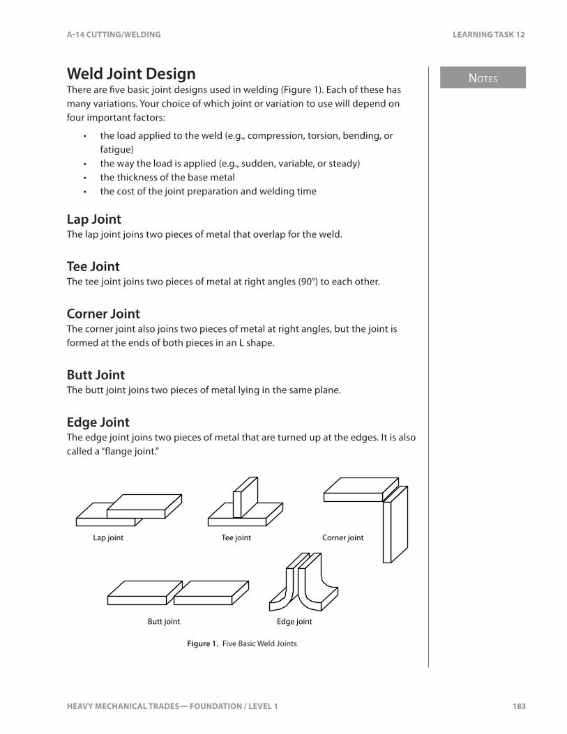
HEAVY MECHANICAL TRADES— FOUNDATION / LEVEL 1 183
NOTES
A-14 CUTTING/WELDING LEARNING TASK 12
Weld Joint DesignThere are �ve basic joint designs used in welding (Figure 1). Each of these has many variations. Your choice of which joint or variation to use will depend on four important factors:
• the load applied to the weld (e.g., compression, torsion, bending, or fatigue)
• the way the load is applied (e.g., sudden, variable, or steady)• the thickness of the base metal• the cost of the joint preparation and welding time
Lap JointThe lap joint joins two pieces of metal that overlap for the weld.
Tee JointThe tee joint joins two pieces of metal at right angles (90°) to each other.
Corner JointThe corner joint also joins two pieces of metal at right angles, but the joint is formed at the ends of both pieces in an L shape.
Butt JointThe butt joint joins two pieces of metal lying in the same plane.
Edge JointThe edge joint joins two pieces of metal that are turned up at the edges. It is also called a “�ange joint.”
Lap joint
Butt joint Edge joint
Tee joint Corner joint
Figure 1. Five Basic Weld Joints

NOTES
184 HEAVY MECHANICAL TRADES— FOUNDATION / LEVEL 1
LEARNING TASK 12 A-14 CUTTING/WELDING
Variations in Weld Joint DesignOn thicker material, the edges must be prepared to get additional weld penetration. There are several ways of preparing the edges of a weld joint.
Lap JointsLap joints need little or no edge preparation. On thicker material, a single bevel is all that is usually required, although such preparations are extremely rare. Lap joints are often used for welds joining two materials of di�erent thickness.
If a weld does not need great strength, a single lap joint might be enough to provide a “tight” joint. Do not use a single lap joint when the weld will be subjected to �uctuating, bending, or twisting loads. For these types of loads, weld the joint from both sides, or use a double lap joint (Figure 2).
Single lap joint Double lap joint
Figure 2. Variations of Lap Joints
Lap joints have two signi�cant drawbacks. As with tee joints, the material requirements are high. That means you can only get maximum tensile strength when the overlap is �ve times the thickness of the thinner member. Also, the joint tends to lose its strength under stress loading.
Tee JointsThe square tee joint requires no edge preparation. It’s widely used because it’s relatively inexpensive and easy to �t. On thicker material, the edges might be prepared with a single bevel, double bevel, single J, or double J (Figure 3).
Single bevel Double bevel Single J Double J
Figure 3. Edge Preparation for Tee Joint

HEAVY MECHANICAL TRADES— FOUNDATION / LEVEL 1 185
NOTES
A-14 CUTTING/WELDING LEARNING TASK 12
Tee joints that are welded on one side are only satisfactory for light static loads. For heavy or �uctuating loads, tee joints need to be welded on both sides to increase their strength.
Tee joints are relatively easy to design and they provide maximum access for welding. However, the chance of them being distorted is high. They are also expensive because they need more �ller weld material, especially on larger tee joints and on joints that need to be welded from both sides.
Corner JointsThere are two types of corner joints: the open corner and the closed corner (Figure 4).
Open Closed
Figure 4. Types of Corner Joints
Welders use the open corner joint more often than the closed corner joint because penetration is usually excellent, resulting in a full-strength weld. With the closed corner, penetration is impossible on all but light-gauge sheet metal. On thicker material, you must prepare the edges (Figure 5). A small root opening can be left between the two pieces in order to ensure full penetration.
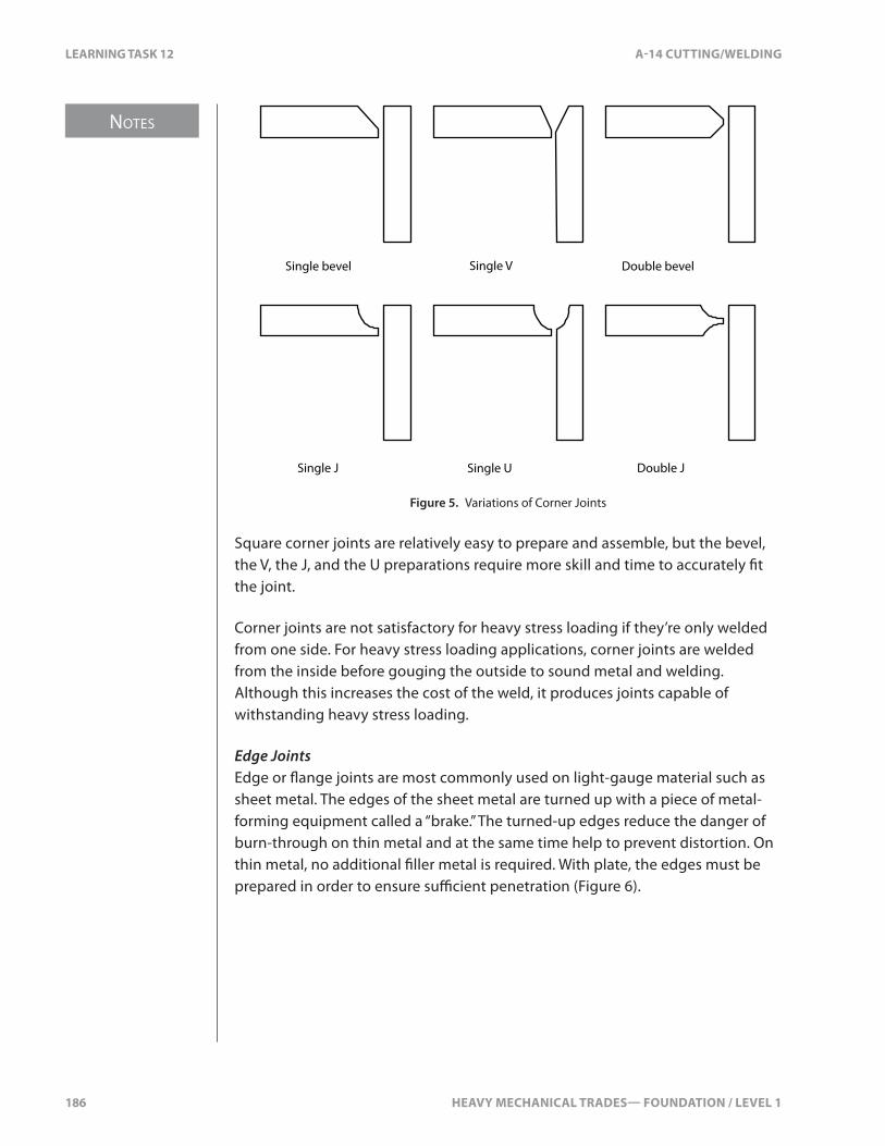
NOTES
186 HEAVY MECHANICAL TRADES— FOUNDATION / LEVEL 1
LEARNING TASK 12 A-14 CUTTING/WELDING
Single bevel Single V Double bevel
Double JSingle USingle J
Figure 5. Variations of Corner Joints
Square corner joints are relatively easy to prepare and assemble, but the bevel, the V, the J, and the U preparations require more skill and time to accurately �t the joint.
Corner joints are not satisfactory for heavy stress loading if they’re only welded from one side. For heavy stress loading applications, corner joints are welded from the inside before gouging the outside to sound metal and welding. Although this increases the cost of the weld, it produces joints capable of withstanding heavy stress loading.
Edge JointsEdge or �ange joints are most commonly used on light-gauge material such as sheet metal. The edges of the sheet metal are turned up with a piece of metal-forming equipment called a “brake.” The turned-up edges reduce the danger of burn-through on thin metal and at the same time help to prevent distortion. On thin metal, no additional �ller metal is required. With plate, the edges must be prepared in order to ensure su�cient penetration (Figure 6).
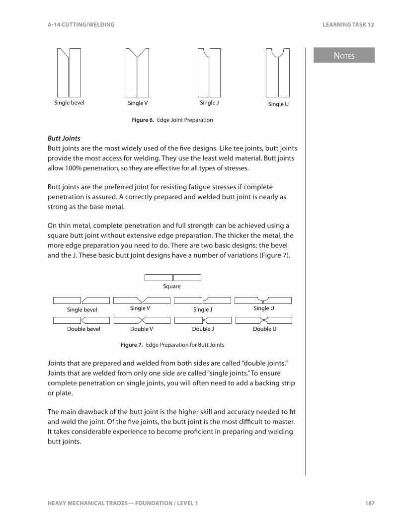
HEAVY MECHANICAL TRADES— FOUNDATION / LEVEL 1 187
NOTES
A-14 CUTTING/WELDING LEARNING TASK 12
Single bevel Single V Single J Single U
Figure 6. Edge Joint Preparation
Butt JointsButt joints are the most widely used of the �ve designs. Like tee joints, butt joints provide the most access for welding. They use the least weld material. Butt joints allow 100% penetration, so they are e�ective for all types of stresses.
Butt joints are the preferred joint for resisting fatigue stresses if complete penetration is assured. A correctly prepared and welded butt joint is nearly as strong as the base metal.
On thin metal, complete penetration and full strength can be achieved using a square butt joint without extensive edge preparation. The thicker the metal, the more edge preparation you need to do. There are two basic designs: the bevel and the J. These basic butt joint designs have a number of variations (Figure 7).
Single bevel Single J Single USingle V
Square
Double V Double J Double UDouble bevel
Figure 7. Edge Preparation for Butt Joints
Joints that are prepared and welded from both sides are called “double joints.” Joints that are welded from only one side are called “single joints.” To ensure complete penetration on single joints, you will often need to add a backing strip or plate.
The main drawback of the butt joint is the higher skill and accuracy needed to �t and weld the joint. Of the �ve joints, the butt joint is the most di�cult to master. It takes considerable experience to become pro�cient in preparing and welding butt joints.

NOTES
188 HEAVY MECHANICAL TRADES— FOUNDATION / LEVEL 1
LEARNING TASK 12 A-14 CUTTING/WELDING
Bevel AnglesThe common bevel angles used in preparing the edge of materials are:
• 30° most common bevel for plate; provides a 60° included angle• 37.5° a common bevel angle on pipe ends used in butt joints; gives
a 75° included angle• 45° a wider than usual bevel angle for V butt joints; gives a
90° included angle
The 90° opening requires a greater amount of weld. Narrower angles are used unless there is a need for more access to the bottom of the weld joint, as with cast iron and aluminum. Single-bevel joints are commonly 30–45°.
Welding PositionsBasic Weld PositionsThere are four basic welding positions: �at, horizontal, vertical, and overhead. Welding techniques for the four positions vary according to the ease of depositing the weld metal. Welding in the �at position is generally faster and less tiring than in the other three positions. Whenever possible, you should try to place your work piece in the �at position.
The term “welding out of position” means welding in any position other than �at. There are four positions that are used for plate and two that are for pipe (Figure 8).
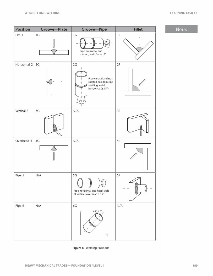
HEAVY MECHANICAL TRADES— FOUNDATION / LEVEL 1 189
NOTES
A-14 CUTTING/WELDING LEARNING TASK 12
Position Groove—Plate Groove—Pipe FilletFlat 1 1G 1G
15º
15º
Pipe horizontal and rotated, weld �at ± 15º
1F
Horizontal 2 2G 2G
15º 15º
Pipe vertical and not
welding, weld horizontal (± 15º)
2F
Vertical 3 3G N/A 3F
Overhead 4 4G N/A 4F
Pipe 5 N/A 5G
15º15º
at vertical, overhead ± 15º
5F
Pipe 6 N/A 6G
V
H
45º ± 5º
N/A
Figure 8. Welding Positions
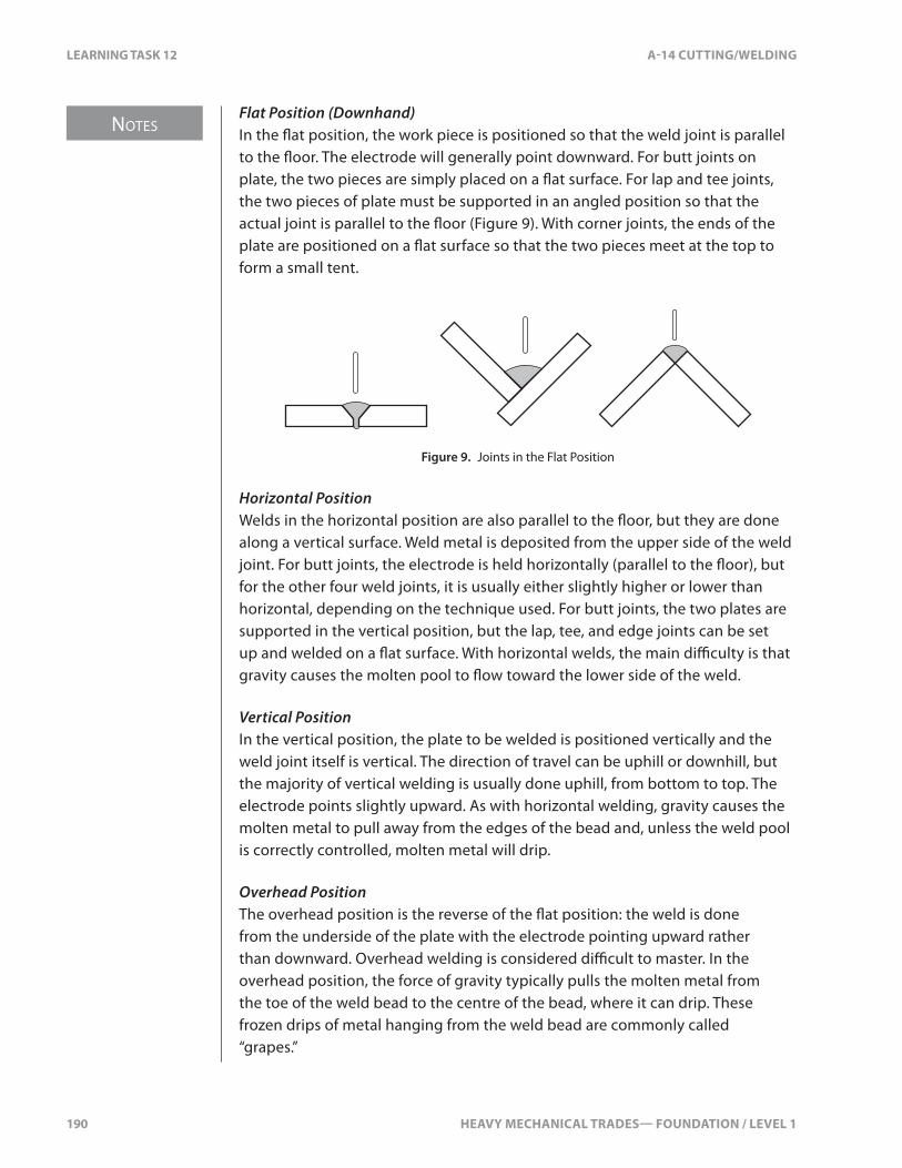
NOTES
190 HEAVY MECHANICAL TRADES— FOUNDATION / LEVEL 1
LEARNING TASK 12 A-14 CUTTING/WELDING
Flat Position (Downhand)In the �at position, the work piece is positioned so that the weld joint is parallel to the �oor. The electrode will generally point downward. For butt joints on plate, the two pieces are simply placed on a �at surface. For lap and tee joints, the two pieces of plate must be supported in an angled position so that the actual joint is parallel to the �oor (Figure 9). With corner joints, the ends of the plate are positioned on a �at surface so that the two pieces meet at the top to form a small tent.
Figure 9. Joints in the Flat Position
Horizontal PositionWelds in the horizontal position are also parallel to the �oor, but they are done along a vertical surface. Weld metal is deposited from the upper side of the weld joint. For butt joints, the electrode is held horizontally (parallel to the �oor), but for the other four weld joints, it is usually either slightly higher or lower than horizontal, depending on the technique used. For butt joints, the two plates are supported in the vertical position, but the lap, tee, and edge joints can be set up and welded on a �at surface. With horizontal welds, the main di�culty is that gravity causes the molten pool to �ow toward the lower side of the weld.
Vertical PositionIn the vertical position, the plate to be welded is positioned vertically and the weld joint itself is vertical. The direction of travel can be uphill or downhill, but the majority of vertical welding is usually done uphill, from bottom to top. The electrode points slightly upward. As with horizontal welding, gravity causes the molten metal to pull away from the edges of the bead and, unless the weld pool is correctly controlled, molten metal will drip.
Overhead PositionThe overhead position is the reverse of the �at position: the weld is done from the underside of the plate with the electrode pointing upward rather than downward. Overhead welding is considered di�cult to master. In the overhead position, the force of gravity typically pulls the molten metal from the toe of the weld bead to the centre of the bead, where it can drip. These frozen drips of metal hanging from the weld bead are commonly called “grapes.”
HEAVY MECHANICAL TRADES— FOUNDATION / LEVEL 1 191
NOTES
A-14 CUTTING/WELDING LEARNING TASK 12
Abbreviations for Weld PositionsIn the welding trade, abbreviations can be used to indicate the type of weld and the welding position. Letter abbreviations are used to indicate weld type, as follows:
• F: �llet weld• G: groove weld
Each weld position is designated with a number, as follows:
• 1: �at position (pipe rolled)• 2: horizontal position• 3: vertical position• 4: overhead position• 5: pipe—axis of pipe �xed at the horizontal• 6: pipe—axis of pipe �xed at a 45° incline
The position number and the letter abbreviation are used together. For example:
• 1G is a groove weld in the �at position.• 3F is a �llet weld in the vertical position.• 4G is a groove weld in the overhead position.• 5G is a groove weld in a pipe with the axis of the pipe �xed at
the horizontal.
A common weld joint design is a single-bevel butt joint with a speci�ed root opening and a backing bar. This is called a “GF weld,” meaning that it is a combined groove and �llet weld. The welding sequence requires a �llet weld to join the backing bar to the square edge of the joint. The �llet weld and the bevelled edge then form a vee-groove joint. If this joint was to be done in the vertical position on plate, it would be called a “3GF position.”
The single-bevel butt joint with backing is commonly used as a welding quali�cation test as it tests your ability to weld a groove weld and a �llet weld all in one exercise. You should expect to regularly face similar quali�cation tests for CWB quali�cation and Welder certi�cation.
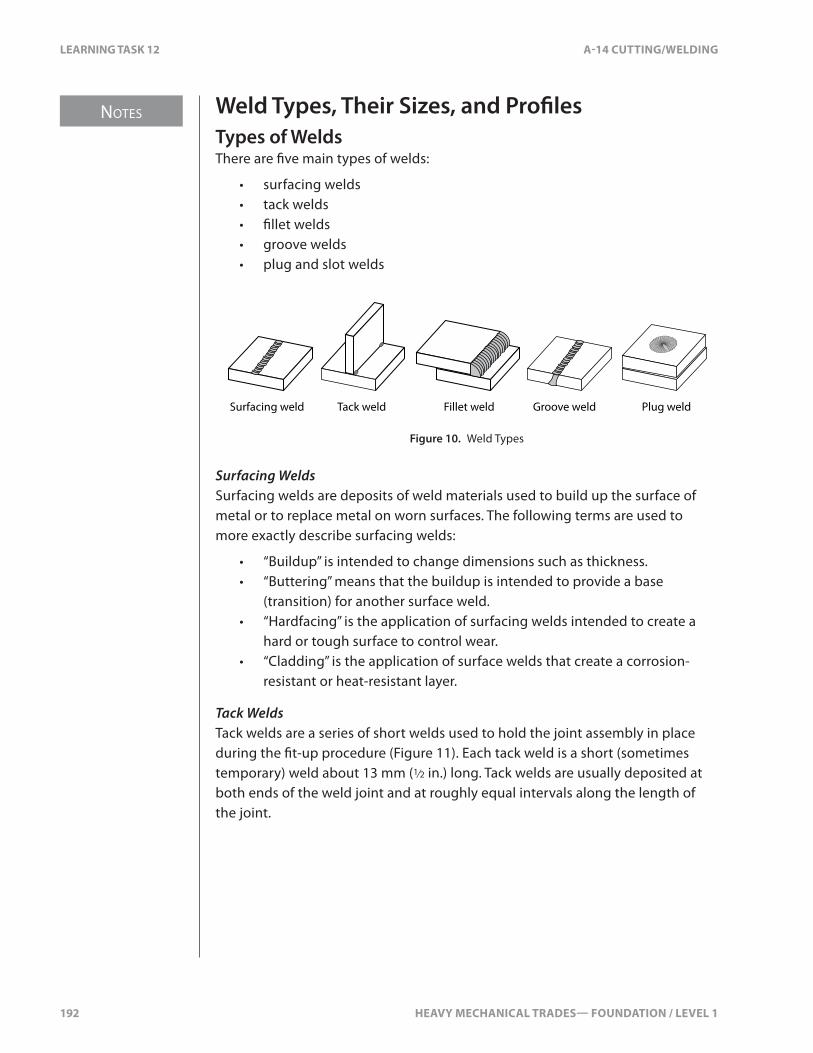
NOTES
192 HEAVY MECHANICAL TRADES— FOUNDATION / LEVEL 1
LEARNING TASK 12 A-14 CUTTING/WELDING
Weld Types, Their Sizes, and Pro�lesTypes of WeldsThere are �ve main types of welds:
• surfacing welds• tack welds• �llet welds• groove welds• plug and slot welds
Surfacing weld Fillet weld Groove weld Plug weldTack weld
Figure 10. Weld Types
Surfacing WeldsSurfacing welds are deposits of weld materials used to build up the surface of metal or to replace metal on worn surfaces. The following terms are used to more exactly describe surfacing welds:
• “Buildup” is intended to change dimensions such as thickness.• “Buttering” means that the buildup is intended to provide a base
(transition) for another surface weld.• “Hardfacing” is the application of surfacing welds intended to create a
hard or tough surface to control wear.• “Cladding” is the application of surface welds that create a corrosion-
resistant or heat-resistant layer.
Tack WeldsTack welds are a series of short welds used to hold the joint assembly in place during the �t-up procedure (Figure 11). Each tack weld is a short (sometimes temporary) weld about 13 mm (1⁄2 in.) long. Tack welds are usually deposited at both ends of the weld joint and at roughly equal intervals along the length of the joint.
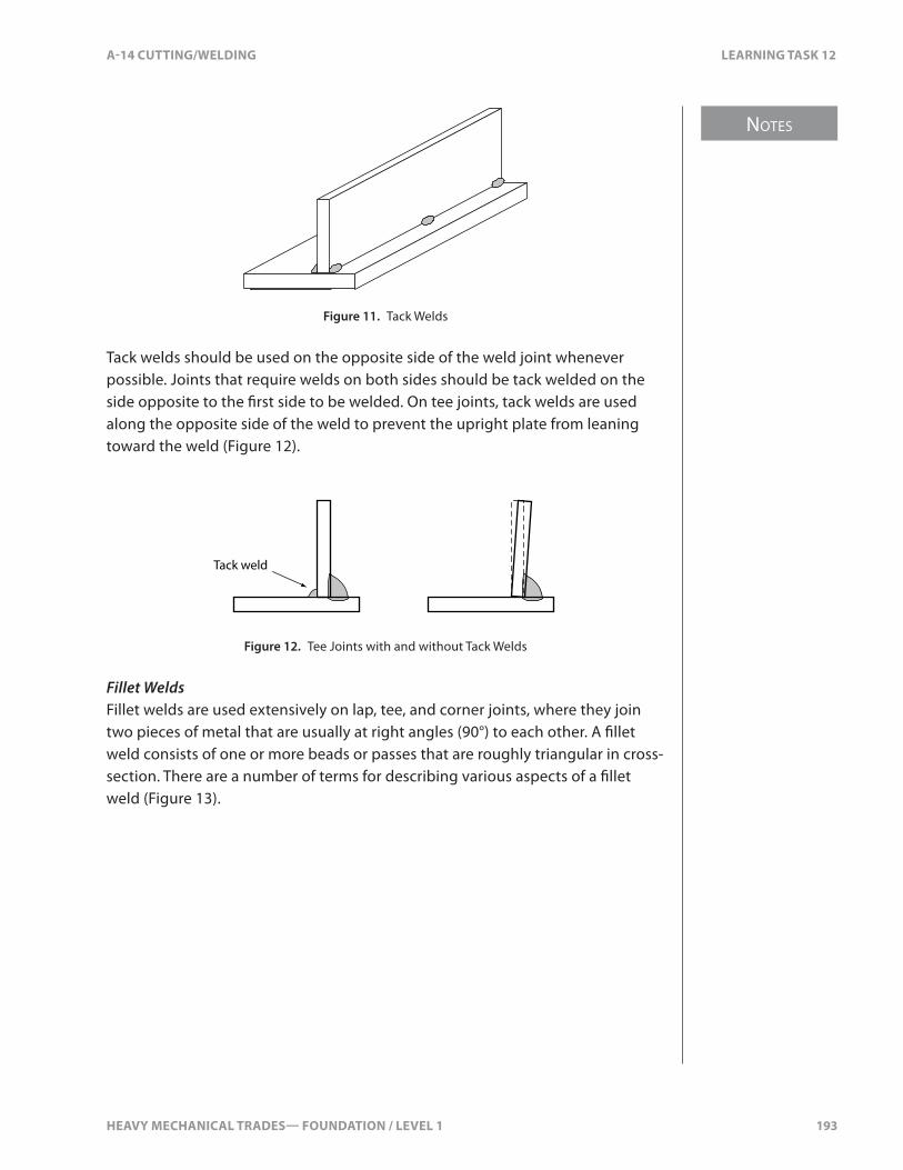
HEAVY MECHANICAL TRADES— FOUNDATION / LEVEL 1 193
NOTES
A-14 CUTTING/WELDING LEARNING TASK 12
Figure 11. Tack Welds
Tack welds should be used on the opposite side of the weld joint whenever possible. Joints that require welds on both sides should be tack welded on the side opposite to the �rst side to be welded. On tee joints, tack welds are used along the opposite side of the weld to prevent the upright plate from leaning toward the weld (Figure 12).
Tack weld
Figure 12. Tee Joints with and without Tack Welds
Fillet WeldsFillet welds are used extensively on lap, tee, and corner joints, where they join two pieces of metal that are usually at right angles (90°) to each other. A �llet weld consists of one or more beads or passes that are roughly triangular in cross-section. There are a number of terms for describing various aspects of a �llet weld (Figure 13).

NOTES
194 HEAVY MECHANICAL TRADES— FOUNDATION / LEVEL 1
LEARNING TASK 12 A-14 CUTTING/WELDING
Leg
Leg
Toe
Face
Throat
Depth of fusion or bond
Root
Root penetration
Figure 13. Fillet Weld
The ideal �llet weld is characterized by:
• joint faces at right angles (90°)• face that is �at or slightly convex• toes that merge smoothly with the surface of the joint members• legs of equal length
In many cases, �llet welds are more economical than groove welds because they’re easier to assemble and require less edge preparation. On the other hand, they usually use more weld �ller metal, and are less able to withstand stress loads.
Fillet welds are not considered capable of carrying stress loads unless their length is at least four times the leg length of the weld. For material up to 25 mm (1 in.) thick, stress-carrying �llet welds should not have a leg length of less than 10 mm (3⁄8 in.).
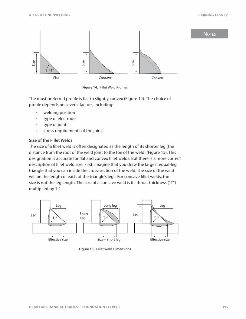
HEAVY MECHANICAL TRADES— FOUNDATION / LEVEL 1 195
NOTES
A-14 CUTTING/WELDING LEARNING TASK 12
Flat
45º
Size
Size
Size
Concave Convex
Figure 14. Fillet Weld Profiles
The most preferred pro�le is �at to slightly convex (Figure 14). The choice of pro�le depends on several factors, including:
• welding position• type of electrode• type of joint• stress requirements of the joint
Size of the Fillet WeldsThe size of a �llet weld is often designated as the length of its shorter leg (the distance from the root of the weld joint to the toe of the weld) (Figure 15). This designation is accurate for �at and convex �llet welds. But there is a more correct description of �llet weld size. First, imagine that you draw the largest equal-leg triangle that you can inside the cross-section of the weld. The size of the weld will be the length of each of the triangle’s legs. For concave �llet welds, the size is not the leg length. The size of a concave weld is its throat thickness (“T”) multiplied by 1.4.
Leg
Short Leg
Long leg
Size = short leg
Leg Leg
Leg
T T T
Effective size Effective size
Figure 15. Fillet Weld Dimensions

NOTES
196 HEAVY MECHANICAL TRADES— FOUNDATION / LEVEL 1
LEARNING TASK 12 A-14 CUTTING/WELDING
Acceptable Fillet Weld Pro�lesThe three basic weld pro�les are �at, concave, and convex. However, every weld will be slightly di�erent. You need to check each weld to make sure its pro�le is acceptable (Figure 16).
Size
Size
Size
Size
Size Size
Size
Size
Size
Concave Flat
Convex
Convexity (C) must not exceed 0.07 × face width + 1.5 mm (1⁄16")
Excessive undercut Overlap Insufficient leg
Excessive convexityInsufficient throat
Unacceptable fillet weld profiles
45º
C CSi
zeAcceptable fillet weld profiles
Size
Figure 16. Acceptable and Unacceptable Fillet Weld Profiles
On �at or concave �llet welds, the e�ective or theoretical throat is usually the same as the actual throat thickness. On convex �llet welds, the actual throat dimension is more than the e�ective throat, but this extra weld �ller metal does not increase the strength of the weld. For this reason, excessively convex �llet welds are undesirable.

HEAVY MECHANICAL TRADES— FOUNDATION / LEVEL 1 197
NOTES
A-14 CUTTING/WELDING LEARNING TASK 12
For similar reasons, excessively concave �llet welds are also undesirable. The longer leg length requires additional weld material that does not contribute to the strength of the weld. A �at or convex �llet weld with the same e�ective throat (strength) uses less weld material and is a more economical weld.
Note on the �at pro�le (Figure 16) the toes of the weld must be at a 45° angle to the face of the weld. With convex pro�les, the convexity (C) must not exceed 0.07 x face width + 1.5 mm (1⁄16 in.).
Of the three pro�les, convex �llet welds are much less susceptible to shrinkage cracking than concave and �at �llet welds. Concave and �at �llet welds are much more likely to crack, especially on heat-sensitive metals such as high-carbon steels. There are also fewer problems with undercutting on convex �llets than on concave or �at �llets.
Concave �llet welds have two major advantages over the other two pro�les:
• They provide a smoother contour at the toe of the weld.• They provide a greater surface area for the distribution of stress loads.
Concave �llet welds are preferred for joints that are subjected to fatigue stresses. Concave �llet welds are also used in such applications as inside grain feed chutes, where free �ow is desired.
Groove WeldsGroove welds �ll in the gap or groove between two pieces of metal. Groove welds are most commonly used on butt joints. The weld on an open corner joint or on specially prepared lap and tee joints can sometimes be considered a groove weld.
Groove welds consist of a root bead, �ll passes, and a cap (Figure 17). The number of passes will vary depending on the thickness of the metal. On thinner metal, the �ll pass and cap can be combined into one pass. In some cases, a single pass is adequate for the entire weld.
Cap pass
Fill passes
Root pass
Root face
Root opening
Figure 17. Multi-pass Groove Weld

NOTES
198 HEAVY MECHANICAL TRADES— FOUNDATION / LEVEL 1
LEARNING TASK 12 A-14 CUTTING/WELDING
The signi�cant dimensions of groove welds include the root opening, the root face, the included angle, the thickness, and the throat (Figure 18). On bevelled joints, the bevel angle is important. On groove joints with a J preparation, the root radius is signi�cant.
Groove or included angle
Root opening
Root opening
Root radius
Thro
at
Root face
Root face
Included angle
Bevel angle
Thickness (T)
Thickness (T)
Figure 18. Groove Weld Dimensions
The size of the root opening, the root face, the included angle, and the root radius all a�ect the amount of weld material required and the depth of penetration. For example, too large a root opening, root face, or included angle will result in excessive penetration and the deposition of unnecessary weld metal. On the other hand, dimensions that are too narrow will make full penetration extremely di�cult, if not impossible. If the root radius on a U-joint is too great, you will deposit too much weld material, and the possibility of uncontrollable distortion increases.
These dimensions will depend on the material thickness, the electrode size, and the welding process.
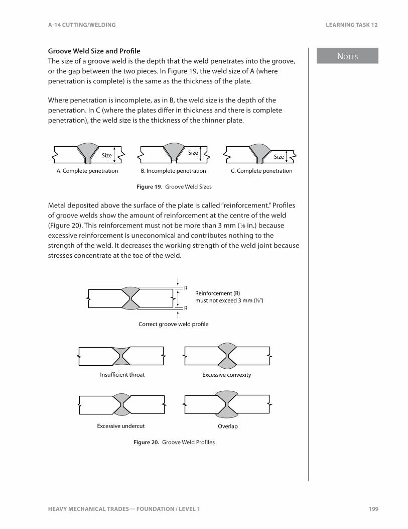
HEAVY MECHANICAL TRADES— FOUNDATION / LEVEL 1 199
NOTES
A-14 CUTTING/WELDING LEARNING TASK 12
Groove Weld Size and Pro�leThe size of a groove weld is the depth that the weld penetrates into the groove, or the gap between the two pieces. In Figure 19, the weld size of A (where penetration is complete) is the same as the thickness of the plate.
Where penetration is incomplete, as in B, the weld size is the depth of the penetration. In C (where the plates di�er in thickness and there is complete penetration), the weld size is the thickness of the thinner plate.
A. Complete penetration B. Incomplete penetration C. Complete penetration
Size SizeSize
Figure 19. Groove Weld Sizes
Metal deposited above the surface of the plate is called “reinforcement.” Pro�les of groove welds show the amount of reinforcement at the centre of the weld (Figure 20). This reinforcement must not be more than 3 mm (1⁄8 in.) because excessive reinforcement is uneconomical and contributes nothing to the strength of the weld. It decreases the working strength of the weld joint because stresses concentrate at the toe of the weld.
Insu�cient throat
Correct groove weld pro�le
Excessive convexity
Excessive undercut Overlap
Reinforcement (R) must not exceed 3 mm (1⁄8")
R
R
Figure 20. Groove Weld Profiles
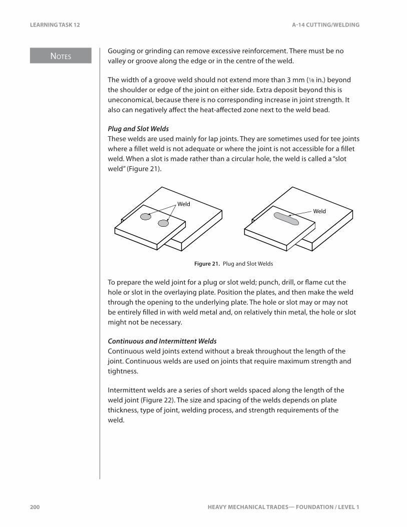
NOTES
200 HEAVY MECHANICAL TRADES— FOUNDATION / LEVEL 1
LEARNING TASK 12 A-14 CUTTING/WELDING
Gouging or grinding can remove excessive reinforcement. There must be no valley or groove along the edge or in the centre of the weld.
The width of a groove weld should not extend more than 3 mm (1⁄8 in.) beyond the shoulder or edge of the joint on either side. Extra deposit beyond this is uneconomical, because there is no corresponding increase in joint strength. It also can negatively a�ect the heat-a�ected zone next to the weld bead.
Plug and Slot WeldsThese welds are used mainly for lap joints. They are sometimes used for tee joints where a �llet weld is not adequate or where the joint is not accessible for a �llet weld. When a slot is made rather than a circular hole, the weld is called a “slot weld” (Figure 21).
WeldWeld
Figure 21. Plug and Slot Welds
To prepare the weld joint for a plug or slot weld; punch, drill, or �ame cut the hole or slot in the overlaying plate. Position the plates, and then make the weld through the opening to the underlying plate. The hole or slot may or may not be entirely �lled in with weld metal and, on relatively thin metal, the hole or slot might not be necessary.
Continuous and Intermittent WeldsContinuous weld joints extend without a break throughout the length of the joint. Continuous welds are used on joints that require maximum strength and tightness.
Intermittent welds are a series of short welds spaced along the length of the weld joint (Figure 22). The size and spacing of the welds depends on plate thickness, type of joint, welding process, and strength requirements of the weld.

HEAVY MECHANICAL TRADES— FOUNDATION / LEVEL 1 201
NOTES
A-14 CUTTING/WELDING LEARNING TASK 12
Figure 22. Intermittent Welds
Intermittent welds should not be used on weld joints that must be sealed (airtight or watertight) or require maximum strength. Where permitted, intermittent welding reduces the cost of labour and materials. Intermittent welds are most commonly used on lap and tee joints. They are sometimes used on square butt joints.
Striking the ArcStriking an arc is an important part of the set-up and start. The machine should be set for AC or DC, straight polarity or reverse polarity. The current should be set for the size and type of rod and the thickness of plate. Using the correct striking method will minimize damage to the base metal to be welded and may prevent damage to other parts in the area.
• Procedure 1A: Strike an arc using the scratch method• Procedure 1B: Strike an arc using the tap method
To strike an arc, you simply touch the electrode to the base metal. You must then immediately lift the electrode. The arc forms as soon as the electrode is lifted from the base metal. If you allow the electrode to remain in contact with the base metal, the two will fuse. If you lift the electrode too far from the base metal, the arc will go out.
The tap method is the main method used to strike an arc. It reduces the chance of arc strikes on the surrounding material.
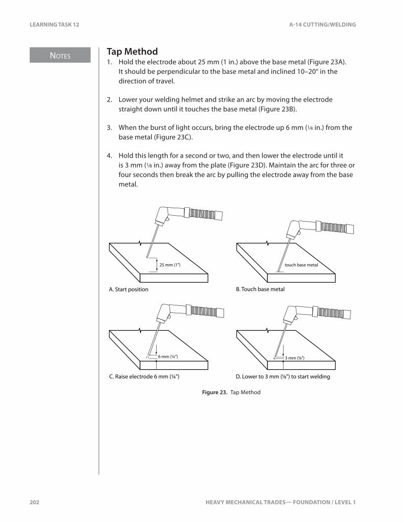
NOTES
202 HEAVY MECHANICAL TRADES— FOUNDATION / LEVEL 1
LEARNING TASK 12 A-14 CUTTING/WELDING
Tap Method1. Hold the electrode about 25 mm (1 in.) above the base metal (Figure 23A).
It should be perpendicular to the base metal and inclined 10–20° in the direction of travel.
2. Lower your welding helmet and strike an arc by moving the electrode straight down until it touches the base metal (Figure 23B).
3. When the burst of light occurs, bring the electrode up 6 mm (1⁄4 in.) from the base metal (Figure 23C).
4. Hold this length for a second or two, and then lower the electrode until it is 3 mm (1⁄8 in.) away from the plate (Figure 23D). Maintain the arc for three or four seconds then break the arc by pulling the electrode away from the base metal.
25 mm (1")
6 mm (¼")
touch base metal
A. Start position B. Touch base metal
C. Raise electrode 6 mm (¼") D. Lower to 3 mm (1⁄8") to start welding
3 mm (1⁄8")
Figure 23. Tap Method
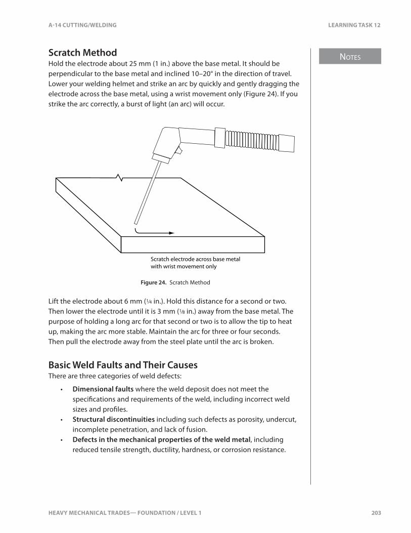
HEAVY MECHANICAL TRADES— FOUNDATION / LEVEL 1 203
NOTES
A-14 CUTTING/WELDING LEARNING TASK 12
Scratch MethodHold the electrode about 25 mm (1 in.) above the base metal. It should be perpendicular to the base metal and inclined 10–20° in the direction of travel. Lower your welding helmet and strike an arc by quickly and gently dragging the electrode across the base metal, using a wrist movement only (Figure 24). If you strike the arc correctly, a burst of light (an arc) will occur.
Scratch electrode across base metal with wrist movement only
Figure 24. Scratch Method
Lift the electrode about 6 mm (1⁄4 in.). Hold this distance for a second or two. Then lower the electrode until it is 3 mm (1⁄8 in.) away from the base metal. The purpose of holding a long arc for that second or two is to allow the tip to heat up, making the arc more stable. Maintain the arc for three or four seconds. Then pull the electrode away from the steel plate until the arc is broken.
Basic Weld Faults and Their CausesThere are three categories of weld defects:
• Dimensional faults where the weld deposit does not meet the speci�cations and requirements of the weld, including incorrect weld sizes and pro�les.
• Structural discontinuities including such defects as porosity, undercut, incomplete penetration, and lack of fusion.
• Defects in the mechanical properties of the weld metal, including reduced tensile strength, ductility, hardness, or corrosion resistance.
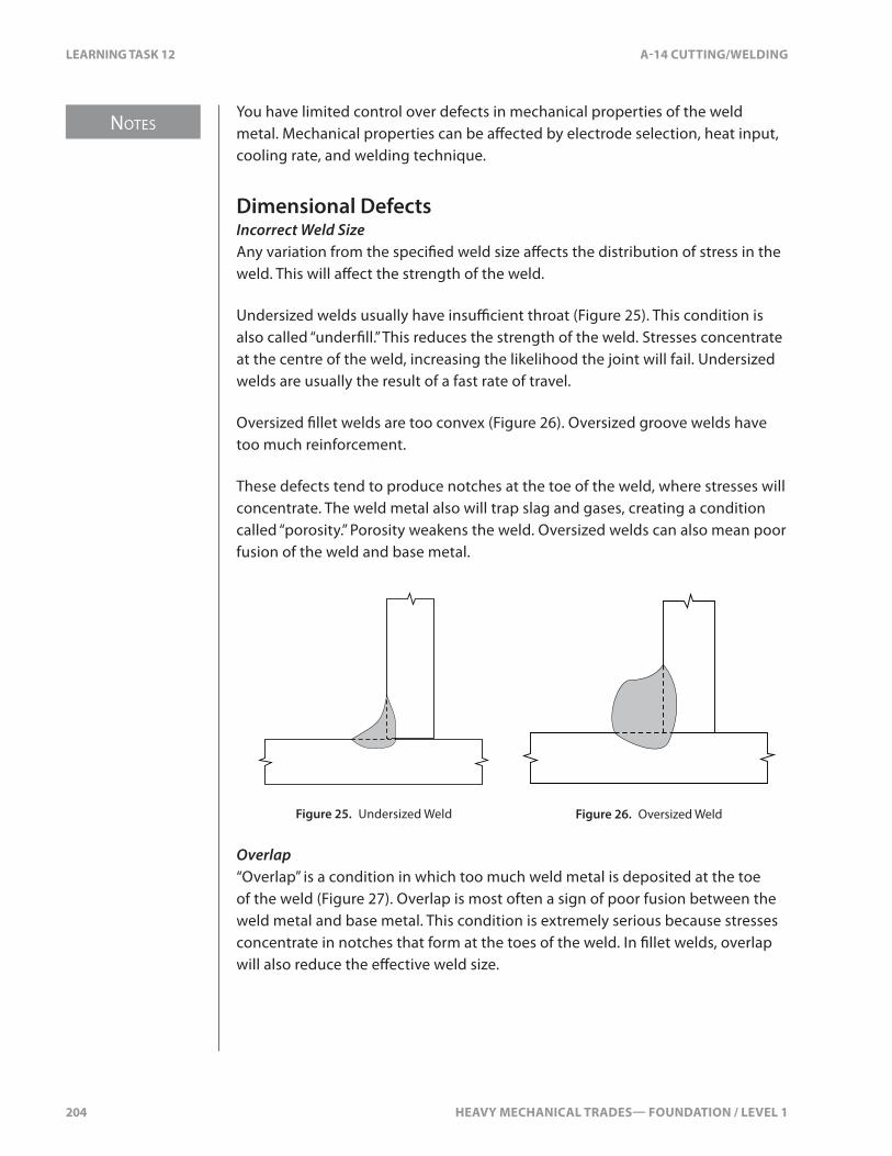
NOTES
204 HEAVY MECHANICAL TRADES— FOUNDATION / LEVEL 1
LEARNING TASK 12 A-14 CUTTING/WELDING
You have limited control over defects in mechanical properties of the weld metal. Mechanical properties can be a�ected by electrode selection, heat input, cooling rate, and welding technique.
Dimensional DefectsIncorrect Weld SizeAny variation from the speci�ed weld size a�ects the distribution of stress in the weld. This will a�ect the strength of the weld.
Undersized welds usually have insu�cient throat (Figure 25). This condition is also called “under�ll.” This reduces the strength of the weld. Stresses concentrate at the centre of the weld, increasing the likelihood the joint will fail. Undersized welds are usually the result of a fast rate of travel.
Oversized �llet welds are too convex (Figure 26). Oversized groove welds have too much reinforcement.
These defects tend to produce notches at the toe of the weld, where stresses will concentrate. The weld metal also will trap slag and gases, creating a condition called “porosity.” Porosity weakens the weld. Oversized welds can also mean poor fusion of the weld and base metal.
Figure 25. Undersized Weld Figure 26. Oversized Weld
Overlap“Overlap” is a condition in which too much weld metal is deposited at the toe of the weld (Figure 27). Overlap is most often a sign of poor fusion between the weld metal and base metal. This condition is extremely serious because stresses concentrate in notches that form at the toes of the weld. In �llet welds, overlap will also reduce the e�ective weld size.
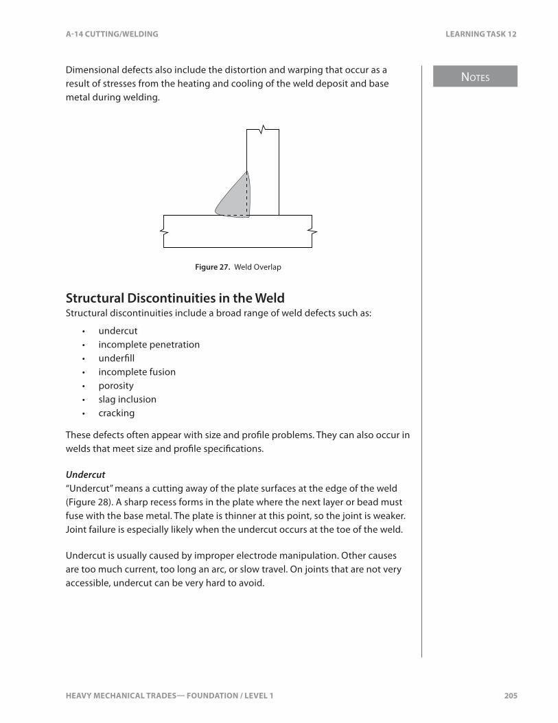
HEAVY MECHANICAL TRADES— FOUNDATION / LEVEL 1 205
NOTES
A-14 CUTTING/WELDING LEARNING TASK 12
Dimensional defects also include the distortion and warping that occur as a result of stresses from the heating and cooling of the weld deposit and base metal during welding.
Figure 27. Weld Overlap
Structural Discontinuities in the WeldStructural discontinuities include a broad range of weld defects such as:
• undercut• incomplete penetration• under�ll• incomplete fusion• porosity• slag inclusion• cracking
These defects often appear with size and pro�le problems. They can also occur in welds that meet size and pro�le speci�cations.
Undercut“Undercut” means a cutting away of the plate surfaces at the edge of the weld (Figure 28). A sharp recess forms in the plate where the next layer or bead must fuse with the base metal. The plate is thinner at this point, so the joint is weaker. Joint failure is especially likely when the undercut occurs at the toe of the weld.
Undercut is usually caused by improper electrode manipulation. Other causes are too much current, too long an arc, or slow travel. On joints that are not very accessible, undercut can be very hard to avoid.

NOTES
206 HEAVY MECHANICAL TRADES— FOUNDATION / LEVEL 1
LEARNING TASK 12 A-14 CUTTING/WELDING
Figure 28. Undercut
Undercut can be corrected. When it occurs at the sidewall of the weld between layers, you can deposit extra weld passes in the groove before depositing the next layer. At the surface of the weld where you can see the defect, you can make extra passes until you reach 3 mm (1⁄8 in.) above the base metal surface, normally the maximum permitted.
Incomplete PenetrationIncomplete penetration is the failure of the weld pool and the base metal to fuse together at the root of the joint. On groove and �llet welds, this defect occurs when the areas above the root reach fusion temperatures before the root does. The molten weld metal forms a bridge across the joint and prevents the arc from reaching the root.
The main cause of incomplete penetration is a joint design that is not suitable for the welding process being used. For single groove welds, there are several conditions that can cause this discontinuity (Figure 29).
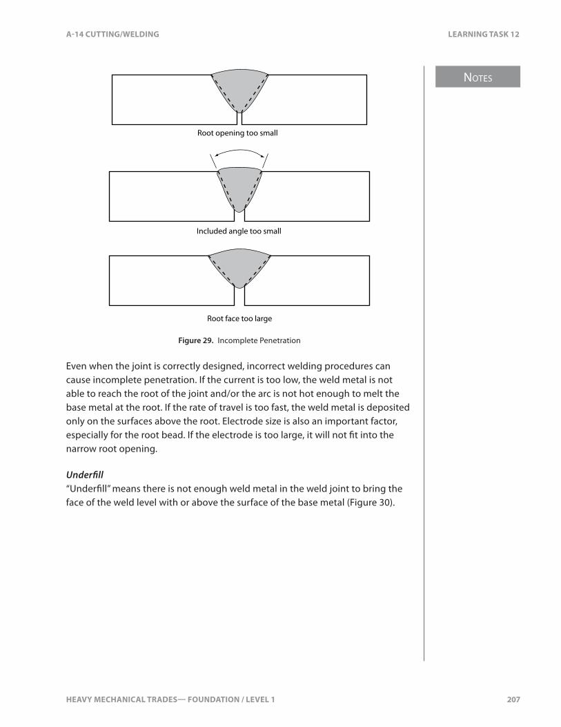
HEAVY MECHANICAL TRADES— FOUNDATION / LEVEL 1 207
NOTES
A-14 CUTTING/WELDING LEARNING TASK 12
Root opening too small
Included angle too small
Root face too large
Figure 29. Incomplete Penetration
Even when the joint is correctly designed, incorrect welding procedures can cause incomplete penetration. If the current is too low, the weld metal is not able to reach the root of the joint and/or the arc is not hot enough to melt the base metal at the root. If the rate of travel is too fast, the weld metal is deposited only on the surfaces above the root. Electrode size is also an important factor, especially for the root bead. If the electrode is too large, it will not �t into the narrow root opening.
Under�ll“Under�ll” means there is not enough weld metal in the weld joint to bring the face of the weld level with or above the surface of the base metal (Figure 30).

NOTES
208 HEAVY MECHANICAL TRADES— FOUNDATION / LEVEL 1
LEARNING TASK 12 A-14 CUTTING/WELDING
Figure 30. Under�ll
Incomplete Fusion“Incomplete fusion” means that the layers of weld metal or the weld metal and base metal did not fuse together completely (Figure 31). This failure can occur at any point in groove and �llet welds. Overlap at the toe of the weld is often a sign of inadequate fusion.
Figure 31. Incomplete Fusion
The usual causes of incomplete fusion are:
• Not heating the base metal or the previously deposited weld metal to the melting point. This usually happens if the electrode is too small, the travel is too fast, or the current is too low.
• Electrode �ux does not dissolve the oxides or other foreign material.
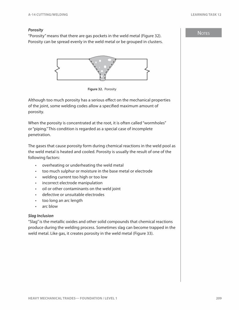
HEAVY MECHANICAL TRADES— FOUNDATION / LEVEL 1 209
NOTES
A-14 CUTTING/WELDING LEARNING TASK 12
Porosity“Porosity” means that there are gas pockets in the weld metal (Figure 32). Porosity can be spread evenly in the weld metal or be grouped in clusters.
Figure 32. Porosity
Although too much porosity has a serious e�ect on the mechanical properties of the joint, some welding codes allow a speci�ed maximum amount of porosity.
When the porosity is concentrated at the root, it is often called “wormholes” or “piping.” This condition is regarded as a special case of incomplete penetration.
The gases that cause porosity form during chemical reactions in the weld pool as the weld metal is heated and cooled. Porosity is usually the result of one of the following factors:
• overheating or underheating the weld metal• too much sulphur or moisture in the base metal or electrode• welding current too high or too low• incorrect electrode manipulation• oil or other contaminants on the weld joint• defective or unsuitable electrodes• too long an arc length• arc blow
Slag Inclusion“Slag” is the metallic oxides and other solid compounds that chemical reactions produce during the welding process. Sometimes slag can become trapped in the weld metal. Like gas, it creates porosity in the weld metal (Figure 33).

NOTES
210 HEAVY MECHANICAL TRADES— FOUNDATION / LEVEL 1
LEARNING TASK 12 A-14 CUTTING/WELDING
Figure 33. Slag Inclusions
In SMAW, slag can form when �ux is trapped in the weld pool. The stirring action of the arc can force the slag into the molten metal. Slag can also be pushed ahead of the arc and then be covered over by the weld pool. Because it’s less dense than molten metal, slag tends to rise to the surface of the pool, where it can be chipped away when the weld is cooled.
Several factors can prevent the release of slag from the weld pool:
• high viscosity of the weld metal• rapid cooling• too low a welding amperage• incorrect manipulation of the electrode• undercut on previous passes
You can prevent slag inclusions by doing the following:
• prepare the weld joint correctly before depositing each weld bead• make sure to maintain the correct weld bead contour for each layer
so that the arc can access the weld joint completely• make sure you clean all slag from the surface of the previous
weld bead
You can also help to promote the release of slag by making sure that the weld pool becomes hot enough to reduce its viscosity (thickness) and by pre- and post-heating to slow down the cooling process.
CrackingCracks are the most dangerous weld defects. They happen when stresses are greater than the ultimate strength of the base metal. Cracking that occurs shortly after the weld metal has been deposited and is just beginning to solidify is called “hot cracking.” Hot cracking is more likely with certain metals, especially the high-alloy steels and high-temperature alloys.
Cracking that occurs later, as the metal is approaching room temperature or after the weld has cooled completely, is called “cold cracking.” Cold cracking is much less common than hot cracking.
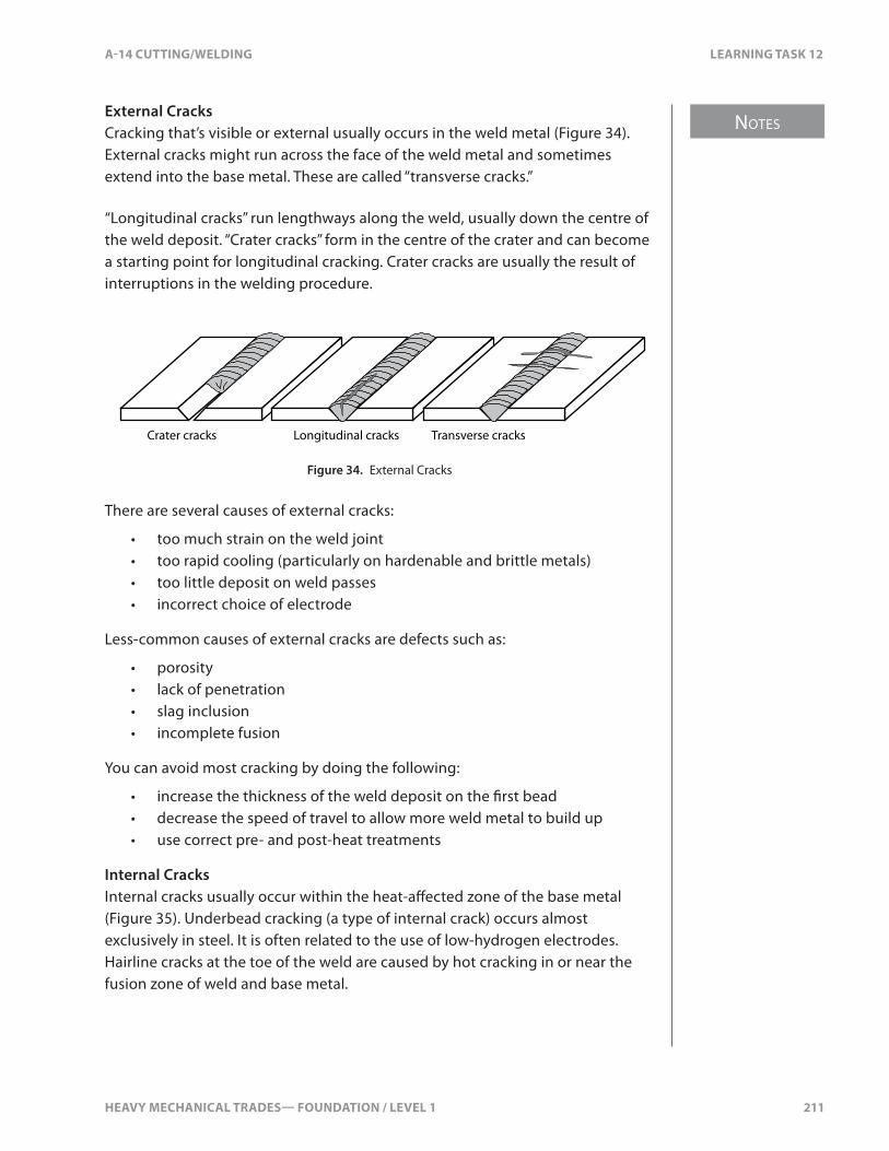
HEAVY MECHANICAL TRADES— FOUNDATION / LEVEL 1 211
NOTES
A-14 CUTTING/WELDING LEARNING TASK 12
External CracksCracking that’s visible or external usually occurs in the weld metal (Figure 34). External cracks might run across the face of the weld metal and sometimes extend into the base metal. These are called “transverse cracks.”
“Longitudinal cracks” run lengthways along the weld, usually down the centre of the weld deposit. “Crater cracks” form in the centre of the crater and can become a starting point for longitudinal cracking. Crater cracks are usually the result of interruptions in the welding procedure.
Crater cracks Longitudinal cracks Transverse cracks
Figure 34. External Cracks
There are several causes of external cracks:
• too much strain on the weld joint• too rapid cooling (particularly on hardenable and brittle metals)• too little deposit on weld passes• incorrect choice of electrode
Less-common causes of external cracks are defects such as:
• porosity• lack of penetration• slag inclusion• incomplete fusion
You can avoid most cracking by doing the following:
• increase the thickness of the weld deposit on the �rst bead• decrease the speed of travel to allow more weld metal to build up• use correct pre- and post-heat treatments
Internal CracksInternal cracks usually occur within the heat-a�ected zone of the base metal (Figure 35). Underbead cracking (a type of internal crack) occurs almost exclusively in steel. It is often related to the use of low-hydrogen electrodes. Hairline cracks at the toe of the weld are caused by hot cracking in or near the fusion zone of weld and base metal.

NOTES
212 HEAVY MECHANICAL TRADES— FOUNDATION / LEVEL 1
LEARNING TASK 12 A-14 CUTTING/WELDING
Internal cracks happen mostly in metals that have been hardened and that are less ductile. They often occur with other weld faults such as undercutting, lack of fusion, incomplete penetration, and slag inclusions.
You can prevent internal cracking by doing the following:
• use low-hydrogen electrodes• follow correct pre- and post-heating procedures• pay careful attention to correct �t-up and welding procedures
Toe cracks
Underbead cracks
Figure 35. Internal Cracks

HEAVY MECHANICAL TRADES— FOUNDATION / LEVEL 1 213
A-14 CUTTING/WELDING SELF TEST 12
SELF TEST 12
1. Where is the best place to locate the ground clamp?
a. at least 1 meter (3 feet) from the electrode
b. as far as possible from the electrode
c. on the same material to be welded
d. as close as possible without touching the material to be welded
2. What joint uses the plug welds?
a. lap joint
b. tee joint
c. but joint
d. corner joint
3. What is the main method to strike an arc?
a. scratch method
b. tap method
c. touch method
d. drag method
4. What type of weld joint has one piece of metal laying over a second piece of metal?
a. corner
b. edge
c. butt
d. lap
5. What is the type of weld that has two metals overlapping each other and welded through a hole or slot?
a. basic
b. plug
c. bottoming
d. penetrating

214 HEAVY MECHANICAL TRADES— FOUNDATION / LEVEL 1

HEAVY MECHANICAL TRADES— FOUNDATION / LEVEL 1 215
NOTES
A-14 CUTTING/WELDING LEARNING TASK 13
LEARNING TASK 13
Weld Mild Steel Using Wire-feed Processes
GMAW, GMAW-P, FCAW, and MCAWGas metal arc welding (GMAW) was patented in the 1940s. Since then, GMAW and the related �ux cored arc welding (FCAW) processes have become major processes used in the welding industry. Their single most important advantage over other welding processes is the continuous �ller metal wire-feed mechanism.
Gas Metal Arc Welding (GMAW)GMAW is extremely versatile and is suitable for welding almost all commercial metal thickness (from light sheet to heavy plate) and structural shapes. The introduction of pulsed gas metal arc welding (GMAW-P), a variation of GMAW, has made the process even more versatile.
GMAW can be used to join many metals: carbon steels, high-strength low-alloy steels, stainless steels, aluminum alloys, magnesium alloys, copper alloys, and nickel alloys.
GMAW was originally developed for production welding. Small, low-cost power sources, wire-feeders, and guns have been developed for use in plants and for maintenance welding. GMAW is used in the auto body repair industry and is popular with hobbyists.
Principles of OperationIn the gas metal arc welding process, an electric arc is drawn between a �ller metal electrode and the base metal (Figure 1). The heat from the arc melts the end of the electrode wire and an area of the base metal. A �ow of shielding gas protects the arc and the molten weld pool from atmospheric contamination.
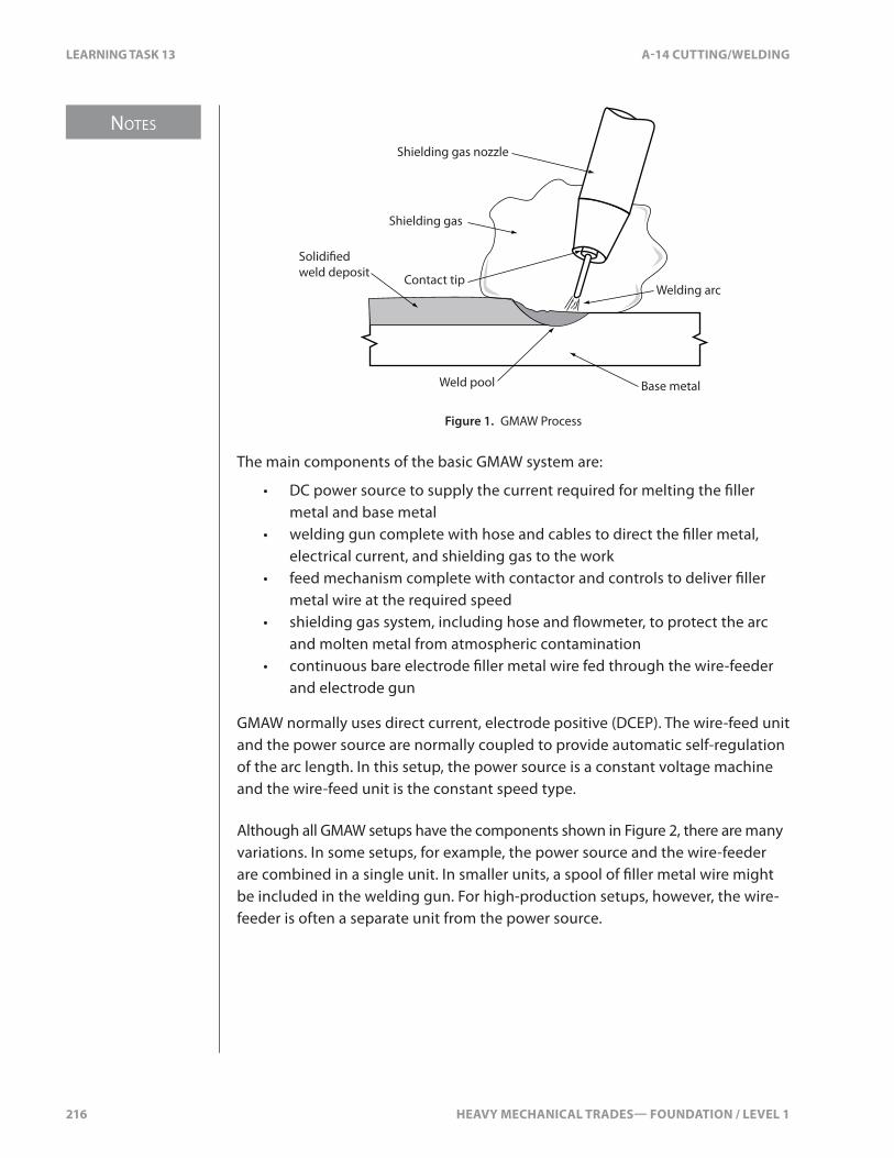
NOTES
216 HEAVY MECHANICAL TRADES— FOUNDATION / LEVEL 1
LEARNING TASK 13 A-14 CUTTING/WELDING
Welding arc
Shielding gas
Solidi�ed weld deposit
Weld pool Base metal
Contact tip
Shielding gas nozzle
Figure 1. GMAW Process
The main components of the basic GMAW system are:
• DC power source to supply the current required for melting the �ller metal and base metal
• welding gun complete with hose and cables to direct the �ller metal, electrical current, and shielding gas to the work
• feed mechanism complete with contactor and controls to deliver �ller metal wire at the required speed
• shielding gas system, including hose and �owmeter, to protect the arc and molten metal from atmospheric contamination
• continuous bare electrode �ller metal wire fed through the wire-feeder and electrode gun
GMAW normally uses direct current, electrode positive (DCEP). The wire-feed unit and the power source are normally coupled to provide automatic self-regulation of the arc length. In this setup, the power source is a constant voltage machine and the wire-feed unit is the constant speed type.
Although all GMAW setups have the components shown in Figure 2, there are many variations. In some setups, for example, the power source and the wire-feeder are combined in a single unit. In smaller units, a spool of �ller metal wire might be included in the welding gun. For high-production setups, however, the wire-feeder is often a separate unit from the power source.

HEAVY MECHANICAL TRADES— FOUNDATION / LEVEL 1 217
NOTES
A-14 CUTTING/WELDING LEARNING TASK 13
+ –
Ground clamp Work leadWire-feed unit
Welding power source
Electrode lead Shielding gas cylinder
Spool of �ller metal wire
Pressure regulator
Flow meter
Welding gun
Figure 2. Basic GMAW Set-up
Flux Cored Arc Welding (FCAW)FCAW is a GMAW process that uses a tubular electrode wire with powdered �ux inside (Figure 3). This process is especially well-suited to welding low-carbon structural steels and low-alloy and stainless steels. It’s also widely used for hardfacing applications.
Solidified slag
Molten slag
Weld metal
Molten metal
Arc
Contact tip
Nozzle
Flux-cored electrode
Shielding gas envelope
Figure 3. FCAW Process

NOTES
218 HEAVY MECHANICAL TRADES— FOUNDATION / LEVEL 1
LEARNING TASK 13 A-14 CUTTING/WELDING
The �ux in the centre of the electrode contains elements similar to the coating on an SMAW electrode. These elements act as deoxidizers, slag formers, and arc stabilizers. In some cases, they can enhance the properties of the weld metal.
Advantages and Disadvantages of FCAWThe main advantages of FCAW (other than continuous feeding, which it shares with GMAW) are deeper penetration, higher deposition rates, and high deposition e�ciency. The deeper penetration means that heavier stock can be welded in fewer passes. Deep penetration also reduces the need for edge preparation with FCAW. On larger thicknesses that require beveling, the bevel and included angles are reduced compared to those prepared for SMAW. Narrow openings mean that you need less �ller weld metal to �ll the joint, saving both �ller metal and welding time.
The main disadvantage of FCAW is its limited application. It can be used only on ferrous metals, including low- and medium-carbon steels, some low-alloy steels, and a limited number of stainless steels. This is because �ller metals have not been developed for other materials.
Another disadvantage is the initial cost of the equipment. The equipment and electrodes are more expensive than those for SMAW, but faster welding speeds mean that this expense can be recovered. When compared to GMAW, post-weld cleanup to remove the slag is an additional expense.
Metal Cored Arc Welding (MCAW)Like FCAW, metal cored arc welding (MCAW) is a continuous wire-feed process that uses a tubular �ller metal wire. The di�erence is that the metal cored wire has no �uxing ingredients inside. Instead, the wire is �lled with powdered metal. Usually, the powdered metal is iron powder with alloying elements. MCAW wires are designed to run best using argon-rich shielding gases.
Advantages and Disadvantages of MCAWThe main advantages of MCAW are:
• low smoke and fume levels• high deposition e�ciency• a broad range of alloy choices• no slag• minimal spatter• good penetration• good bead appearance

HEAVY MECHANICAL TRADES— FOUNDATION / LEVEL 1 219
NOTES
A-14 CUTTING/WELDING LEARNING TASK 13
As with FCAW �ller metal, the manufacturer can easily customize MCAW �ller metal by changing the ingredients of the core material.
Because MCAW has no �ux, the fume levels are lower than for FCAW. Having no �ux and little spatter also contributes to a high deposition e�ciency of 92–96%.
By adding small percentages of other metals such as molybdenum, manganese, chromium, and so on to the metal powder inside the tubular wire, welding �ller metals have been designed to achieve a wide range of metallurgical characteristics. The addition of deoxidizers such as silicon helps reduce the chance of porosity and improves weld pool �uidity.
Spray transfer is recommended for MCAW, therefore weld spatter is minimal. There is more weld spatter when using short-circuit or globular transfer.
One of the main advantages of MCAW is excellent penetration with a good depth-to-width ratio. Lack of fusion or cold lap is rare.
Compared to MCAW, GMAW is a better choice for welding thinner material such as gauge metal and thin wall structural shapes and FCAW is a better choice if the base metal is very rusty or dirty.
Safety Requirements for Semi-automatic Welding ProcessesElectric ShockAs with all arc welding processes, you must take great care to protect yourself from receiving an electric shock. The electric currents used in GMAW are very high. If you become part of the electric circuit at any point, you could receive an electric shock severe enough to kill you. Even a small shock that’s not immediately fatal could be su�cient to cause you to jerk or fall, leading to a serious injury.
Protect yourself from dangerous electrical shock by following these rules:
• The electrode and work (or ground) circuits are electrically “hot” when the power source is on. Never permit contact between “hot” parts of the circuits and bare skin or wet clothing.
• Wear dry, hole-free gloves to insulate your hands.• Always insulate yourself from the welding circuit by using some form
of dry electrical insulation. Welding in damp locations, on metal �oors, gratings, and sca�olds, or in positions such as sitting or laying down increase the possibility of electrical shock. Make certain that the electrical insulation you’re using is large enough to cover your full area of physical contact with the work piece and the work area.

NOTES
220 HEAVY MECHANICAL TRADES— FOUNDATION / LEVEL 1
LEARNING TASK 13 A-14 CUTTING/WELDING
• Always be sure the work lead ground clamp makes a good electrical connection with the work piece. The connection should also be positioned as close as possible to the welding arc as practical.
• As a precaution, it’s a good idea to ground your work piece, or the structure you are welding on, with a secondary ground to earth. This earth ground is meant to be a safety precaution similar to a lightning rod and is not meant to be a part of the welding circuit.
• Maintain the �ller metal wire-feed system, ground clamp, welding lead cables, and welding power source in good, safe operating condition.
• When working above �oor level, use personal fall protection equipment to protect yourself in the event that you get a shock and fall.
Safe Handling of Shielding Gas Cylinders and Pressure RegulatorsAlways handle compressed gas cylinders carefully. When you’re using them, make sure they’re properly secured. Knocks, falls, or rough handling can damage the cylinders, valves, or safety devices and cause leakage or an accident. Cylinder valve protective caps should be hand tightened and kept in place until the cylinder is secured and put into service.
Follow these rules when setting up and using cylinders of shielding gas:
• Properly secure the cylinder.• Before you connect a cylinder pressure regulator to the cylinder valve,
crack open and immediately close the valve to clear it of dust or dirt that otherwise might enter the regulator. When opening a cylinder valve, you should stand to one side of the valve, never in front of it.
• Release the working pressure adjusting screw on the cylinder pressure regulator by turning it counter-clockwise. The �owmeter adjusting valve should be set to closed. Then open the cylinder valve slowly to prevent a rapid surge of high-pressure gas into the cylinder pressure regulator. Again, stand to one side of the valve as you open it. Always shut o� the source of the shielding gas supply to the pressure regulator if it will be left unattended.
Toxic GasesThe main toxic gases associated with GMAW are ozone, nitrogen dioxide, and carbon monoxide. Dangerous gas could also be present as a result of thermal or ultraviolet decomposition of cleaning agents located in the vicinity of welding operations.
HEAVY MECHANICAL TRADES— FOUNDATION / LEVEL 1 221
NOTES
A-14 CUTTING/WELDING LEARNING TASK 13
Degreasing or other cleaning operations should be done in a place where vapours from these operations cannot reach radiation from the welding arc.
OzoneThe ultraviolet light emitted by the GMAW arc acts on the oxygen in the surrounding atmosphere to produce ozone. The amount of ozone produced depends on the intensity and wavelength of the ultraviolet energy, the humidity, and the amount of screening provided by any welding fumes. The ozone concentration will increase as the welding current increases, with the use of argon as the shielding gas and when welding highly re�ective metals such as stainless steel and aluminum.
If the ozone cannot be reduced to a safe level by ventilation or changing the process, supply fresh air to the Welder with an air-supplied respirator or by other means.
Nitrogen DioxideSome test results show that high concentrations of nitrogen dioxide are found only within 150 mm (6 in.) of the welding arc. With normal natural ventilation, these concentrations are quickly reduced to safe levels in your breathing zone, as long as your head stays out of the plume of fumes (and thus out of the plume of welding-generated gases).
Carbon MonoxideThe heat of the welding arc in the GMAW process breaks down the carbon dioxide shielding to form carbon monoxide. The welding process creates only a small amount of carbon monoxide, but the plume of fumes temporarily contains relatively high concentrations of fumes. However, the hot carbon monoxide oxidizes to carbon dioxide so that the concentrations of carbon monoxide become insigni�cant at distances of more than 75–100 mm (3–4 in.) from the welding plume.
Under normal welding conditions there should be no hazard from carbon monoxide. But you will need adequate ventilation to de�ect the plume or to remove the fumes and gases if you’re working in a con�ned space or if you must work with your head over the welding arc where natural ventilation moves the plume of fumes toward your breathing zone.
Toxic Metal FumesThe welding fumes generated by GMAW and FCAW can be controlled by general ventilation, by local exhaust ventilation, or by respiratory protective equipment.
NOTES
222 HEAVY MECHANICAL TRADES— FOUNDATION / LEVEL 1
LEARNING TASK 13 A-14 CUTTING/WELDING
The method of ventilation required to keep the level of toxic substances within your breathing zone at acceptable concentrations depends directly on a number of factors. Among these are the material being welded, the size of the work area, and the degree of con�nement or obstruction to normal air movement where the welding is being done. Each operation should be evaluated separately in order to determine what type of ventilation is required.
Good ventilation is especially important when you’re using self-shielded wires in the FCAW process. These �ller metals distill fumes high in metal particles and �uoride oxides. You should take extra precautions (such as CSA-approved respiratory protective equipment) to avoid inhaling them.
Shielding GasesShielding gases used in GMAW and FCAW can displace oxygen and cause lung damage or death from su�ocation. Always ensure that there is su�cient ventilation. Take special care and attention in con�ned spaces.
Protection Against RadiationThe total radiation (radiant energy) produced by the GMAW process can be higher than that produced by the SMAW process. This is due to the signi�cantly lower amounts of welding fumes and the more exposed welding arc. Generally, the highest ultraviolet radiant energy intensities are produced when using an argon shielding gas and when welding on aluminum. Refer to WorkSafeBC’s website, www.worksafebc.com, and click on OHS Regulation under the “Quick Links.” The minimum suggested �lter lens shades for GMAW and FCAW range from 10–12, depending on the welding current level.
Non-re�ective, �re-retardant clothing is recommended for GMAW. Re�ection of ultraviolet radiation can cause ultraviolet burns to the face and neck underneath the helmet. The greater intensity of the ultraviolet radiation will cause rapid disintegration of untreated cotton clothing. CSA-approved safety eyewear must always be worn. Protect other people in the work area from ultraviolet radiation with suitable non-�ammable, non-re�ective welding screens.

HEAVY MECHANICAL TRADES— FOUNDATION / LEVEL 1 223
NOTES
A-14 CUTTING/WELDING LEARNING TASK 13
Equipment for Semi-automatic and Automatic Filler Metal Wire-feed SystemsThe GMAW system requires light, �exible, and durable equipment that can feed a small-diameter �ller metal wire electrode at a constant rate. The feeder should also keep the �ller metal wire clean and snag-free and provide controls for starting, stopping, and adjusting wire-feed speed. Constant voltage welding power sources need a constant speed wire-feed, so the wire-feed speed must be adjustable for di�erent welding currents.
There are many kinds of wire-feed units, but they generally all consist of a spool or coil of �ller metal electrode wire, a set of drive feed rolls for the wire and an adjustable, constant speed motor to turn the drive rolls.
There are three types of wire-feeders for handling di�erent types of electrode wire: the push-type, the pull-type and the push-pull type (Figure 4). The di�erence between them is in the way the drive rolls feed the electrode wire to the welding gun. The push-type pushes the wire, the pull-type pulls the wire, and the push-pull combines both a pushing and pulling mechanism.
Push
Pull
4.5 m (15')
4.5 m (15')
9 m (30')
PushPull
Figure 4. Feed Mechanics

NOTES
224 HEAVY MECHANICAL TRADES— FOUNDATION / LEVEL 1
LEARNING TASK 13 A-14 CUTTING/WELDING
Push-type Wire-feedThe most common wire-feed system is the push-type. It consists of a support assembly that holds the spool of �ller metal wire, an adjustable constant speed motor and drive roll assembly to pull the �ller metal wire from the spool and push it through the cable assembly to the welding gun, and a wire-feed speed control unit.
The wire-feed assembly is usually a one-piece unit. The �ller metal wire spool support, wire-feed drive motor, and drive rolls are attached to an all-welded frame that is mounted on the welding power source (Figure 5).
Figure 5. Push-type Wire-feed Unit
In some cases, the �ller metal wire-feeder is mounted on an overhead crane to allow you to easily access a larger work area. The wire-feeder and controls can also be combined with the welding power source in a single unit. In another variation, used mainly for maintenance and �eld welding, the wire-feeder is small and portable and can be located a great distance from the welding power source.
The drive rolls clamp the �ller metal wire securely to provide the necessary friction to push the wire through the conduit to the welding gun. The upper drive rolls, or pressure rolls, are adjustable up and down by means of a spring-loaded thumbscrew. This screw controls the pressure of the drive rolls on the wire, which is extremely important. You should apply only enough pressure to drive the wire without slippage. Too much pressure will �atten solid wire or crush �ux-cored wire. Damaged wire will not feed through the conduit and welding gun properly.
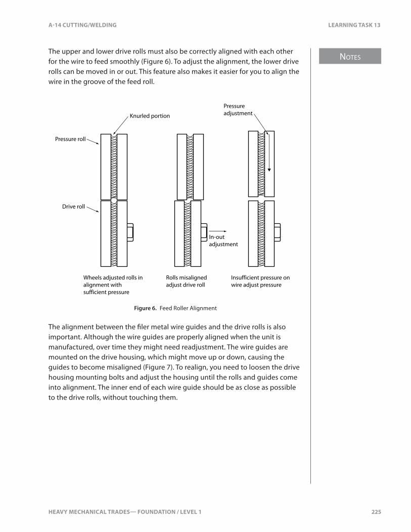
HEAVY MECHANICAL TRADES— FOUNDATION / LEVEL 1 225
NOTES
A-14 CUTTING/WELDING LEARNING TASK 13
The upper and lower drive rolls must also be correctly aligned with each other for the wire to feed smoothly (Figure 6). To adjust the alignment, the lower drive rolls can be moved in or out. This feature also makes it easier for you to align the wire in the groove of the feed roll.
Pressure roll
Knurled portion
Drive roll
Pressure adjustment
In-out adjustment
Wheels adjusted rolls in alignment with sufficient pressure
Rolls misaligned adjust drive roll
Insufficient pressure on wire adjust pressure
Figure 6. Feed Roller Alignment
The alignment between the �ler metal wire guides and the drive rolls is also important. Although the wire guides are properly aligned when the unit is manufactured, over time they might need readjustment. The wire guides are mounted on the drive housing, which might move up or down, causing the guides to become misaligned (Figure 7). To realign, you need to loosen the drive housing mounting bolts and adjust the housing until the rolls and guides come into alignment. The inner end of each wire guide should be as close as possible to the drive rolls, without touching them.

NOTES
226 HEAVY MECHANICAL TRADES— FOUNDATION / LEVEL 1
LEARNING TASK 13 A-14 CUTTING/WELDING
Wire guideDrive roll
Drive housingHousing bolts
Drive rolls and wire guides properly aligned
Wire bent down housing and wire guides too high, lower drive housing
Wire bent up housing and wire guides too low, raise drive housing
Figure 7. Correct and Incorrect Alignment of Wire Guides
Filler metal wire-feed systems are available with two or four drive rolls (Figure 8). The four-roll system o�ers more uniform feed roll pressure, more precise control of the wire-feed speed, and more positive non-slip wire-feeding.
Figure 8. Drive Roller Assembly
To be e�ective in a push-type wire-feeder, the �ller metal electrode wire must be strong enough to be pushed through the conduit without kinking. Low-carbon steel and stainless steel (the “hard” wires) can be readily pushed distances up to 6 m (20 ft.). The “soft” wires (such as aluminum) and very �ne diameter steel wires are much more di�cult to push and kinking or buckling become problems as the distance approaches 3 m (10 ft.). These problems with soft wires have been solved with pull-type feeders with the feed rolls in the welding gun and push-pull systems with feed motors in both the wire-feeder unit and the welding gun.
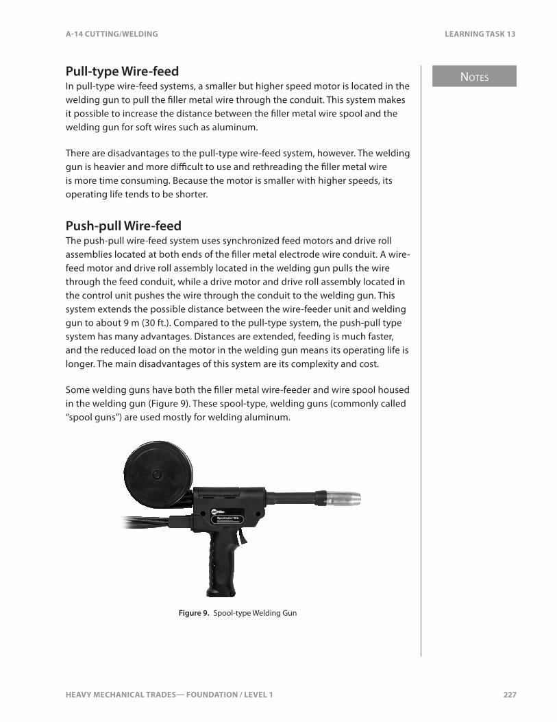
HEAVY MECHANICAL TRADES— FOUNDATION / LEVEL 1 227
NOTES
A-14 CUTTING/WELDING LEARNING TASK 13
Pull-type Wire-feedIn pull-type wire-feed systems, a smaller but higher speed motor is located in the welding gun to pull the �ller metal wire through the conduit. This system makes it possible to increase the distance between the �ller metal wire spool and the welding gun for soft wires such as aluminum.
There are disadvantages to the pull-type wire-feed system, however. The welding gun is heavier and more di�cult to use and rethreading the �ller metal wire is more time consuming. Because the motor is smaller with higher speeds, its operating life tends to be shorter.
Push-pull Wire-feedThe push-pull wire-feed system uses synchronized feed motors and drive roll assemblies located at both ends of the �ller metal electrode wire conduit. A wire-feed motor and drive roll assembly located in the welding gun pulls the wire through the feed conduit, while a drive motor and drive roll assembly located in the control unit pushes the wire through the conduit to the welding gun. This system extends the possible distance between the wire-feeder unit and welding gun to about 9 m (30 ft.). Compared to the pull-type system, the push-pull type system has many advantages. Distances are extended, feeding is much faster, and the reduced load on the motor in the welding gun means its operating life is longer. The main disadvantages of this system are its complexity and cost.
Some welding guns have both the �ller metal wire-feeder and wire spool housed in the welding gun (Figure 9). These spool-type, welding guns (commonly called “spool guns”) are used mostly for welding aluminum.
Figure 9. Spool-type Welding Gun
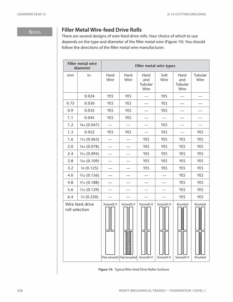
NOTES
228 HEAVY MECHANICAL TRADES— FOUNDATION / LEVEL 1
LEARNING TASK 13 A-14 CUTTING/WELDING
Filler Metal Wire-feed Drive RollsThere are several designs of wire-feed drive rolls. Your choice of which to use depends on the type and diameter of the �ller metal wire (Figure 10). You should follow the directions of the �ller metal wire manufacturer.
Filler metal wire diameter Filler metal wire types
mm in. Hard Wire
Hard Wire
Hard and
Tubular Wire
Soft Wire
Hard and
Tubular Wire
Tubular Wire
0.024 YES YES — YES — —
0.75 0.030 YES YES — YES — —
0.9 0.035 YES YES — YES — —
1.1 0.045 YES YES — — — —
1.2 3⁄64 (0.047) — — — YES — —
1.3 0.052 YES YES — YES — YES
1.6 1⁄16 (0.063) — — YES YES YES YES
2.0 5⁄64 (0.078) — — YES YES YES YES
2.4 3⁄32 (0.094) — — YES YES YES YES
2.8 7⁄64 (0.109) — — YES YES YES YES
3.2 1⁄8 (0.125) — — YES YES YES YES
4.0 5⁄32 (0.156) — — — — YES YES
4.8 3⁄16 (0.188) — — — — YES YES
5.6 7⁄32 (0.129) — — — — YES YES
6.4 1⁄4 (0.250) — — — — YES YES
Wire feed drive roll selection
Smooth V
Flat smooth Flat knurled
Smooth V Smooth V
Smooth V
Smooth V
Smooth V
Knurled
Smooth V
Knurled
Knurled
Figure 10. Typical Wire-feed Drive Roller Surfaces

HEAVY MECHANICAL TRADES— FOUNDATION / LEVEL 1 229
NOTES
A-14 CUTTING/WELDING LEARNING TASK 13
Wire-feed Drive Speed ControlsDepending on the design, the wire-feed drive speed control can be located on the feeder unit or on the welding gun. On many push-type systems, the controls and wire-feed motor are combined in one integrated unit. This unit provides controls for the wire-feed drive speed, shielding gas, water �ow (on water-cooled systems), and welding power (contactor switch). All of these functions (along with starting the wire-feed) are started and stopped by squeezing and releasing the gun trigger.
Solenoids (which control gas and water �ow) are regulated to coincide with the weld start and stop. Most wire-feed units have a wire-feed inch control and a shielding gas purge control. These controls may be a switch type or a button type. The inch control causes the wire-feed drive motor to feed the wire through the electrode conduit to the welding gun. When you are setting-up, use the inch switch to feed the �ller metal wire through to the contact tip and the shielding gas purge control to set the �ow rate of shielding gas. When using these controls, the �ller metal wire is not energized with welding current as it would be if the welding gun trigger was used to perform these operations.
Some �ller metal wire-feeders have a feed or retract control that is used to reverse the direction of the wire-feed. They might also have a shielding gas purge control to clear the system of contaminating air or moisture before you begin welding. On some, there are controls for automatic pre-�ow and post-�ow of shielding gas.
Constant Speed and Variable Speed Metal Wire-feedersConstant-speed wire-feeders are used with constant voltage power sources. For heavy industrial work, these wire-feeders are usually independent of the welding power source. For lighter commercial work, the wire-feeders are often built right into the welding power source. The arc voltage remains steady where set and the wire-feed speed determines the welding amperage.
Variable-speed wire-feeders are used with constant current welding power sources (Figure 11). These units are independent of the welding power source. Amperage is set at the power source and remains steady, and the arc voltage determines the wire-feed speed. A voltage-sensing clamp is attached to the work piece, and the arc voltage is relayed back to the wire-feed drive motor, which speeds up or slows down to maintain the arc length required.
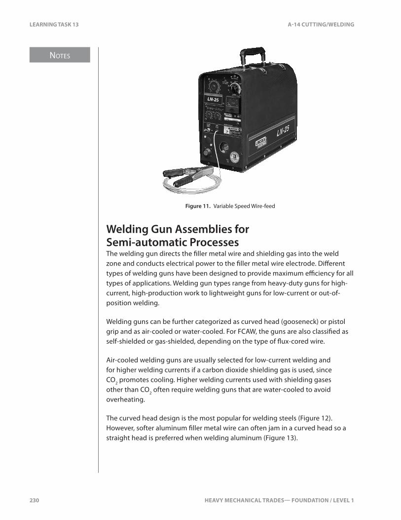
NOTES
230 HEAVY MECHANICAL TRADES— FOUNDATION / LEVEL 1
LEARNING TASK 13 A-14 CUTTING/WELDING
Figure 11. Variable Speed Wire-feed
Welding Gun Assemblies for Semi-automatic ProcessesThe welding gun directs the �ller metal wire and shielding gas into the weld zone and conducts electrical power to the �ller metal wire electrode. Di�erent types of welding guns have been designed to provide maximum e�ciency for all types of applications. Welding gun types range from heavy-duty guns for high-current, high-production work to lightweight guns for low-current or out-of-position welding.
Welding guns can be further categorized as curved head (gooseneck) or pistol grip and as air-cooled or water-cooled. For FCAW, the guns are also classi�ed as self-shielded or gas-shielded, depending on the type of �ux-cored wire.
Air-cooled welding guns are usually selected for low-current welding and for higher welding currents if a carbon dioxide shielding gas is used, since CO2 promotes cooling. Higher welding currents used with shielding gases other than CO2 often require welding guns that are water-cooled to avoid overheating.
The curved head design is the most popular for welding steels (Figure 12). However, softer aluminum �ller metal wire can often jam in a curved head so a straight head is preferred when welding aluminum (Figure 13).
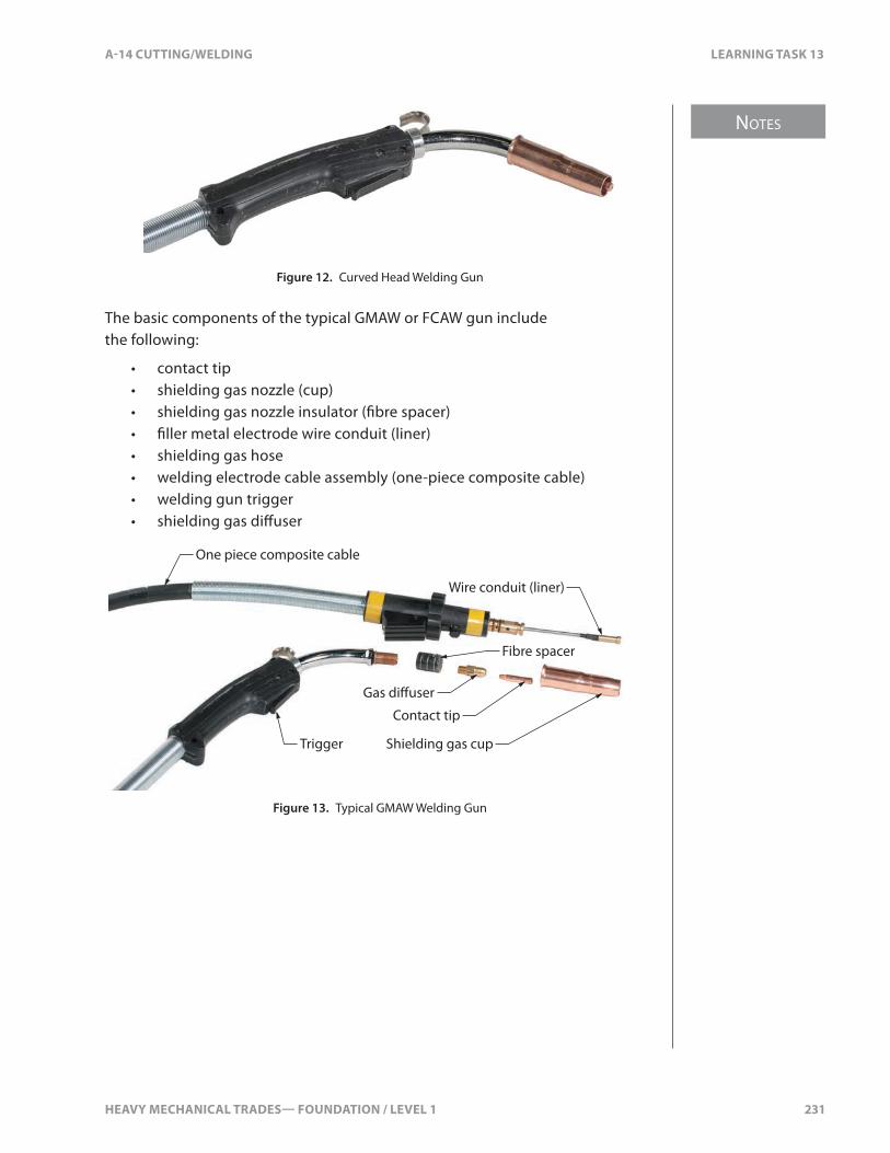
HEAVY MECHANICAL TRADES— FOUNDATION / LEVEL 1 231
NOTES
A-14 CUTTING/WELDING LEARNING TASK 13
Figure 12. Curved Head Welding Gun
The basic components of the typical GMAW or FCAW gun include the following:
• contact tip• shielding gas nozzle (cup)• shielding gas nozzle insulator (�bre spacer)• �ller metal electrode wire conduit (liner)• shielding gas hose• welding electrode cable assembly (one-piece composite cable)• welding gun trigger• shielding gas di�user
One piece composite cable
Wire conduit (liner)
Contact tip
Shielding gas cup
Gas di�user
Fibre spacer
Trigger
Figure 13. Typical GMAW Welding Gun
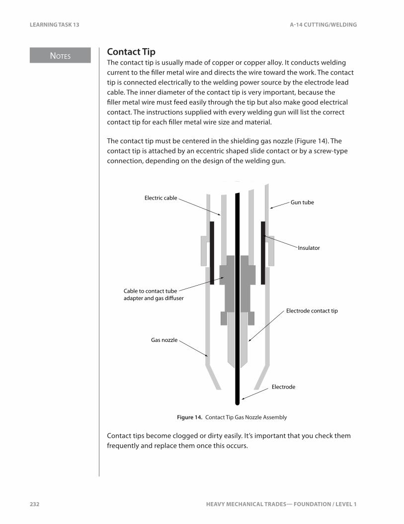
NOTES
232 HEAVY MECHANICAL TRADES— FOUNDATION / LEVEL 1
LEARNING TASK 13 A-14 CUTTING/WELDING
Contact TipThe contact tip is usually made of copper or copper alloy. It conducts welding current to the �ller metal wire and directs the wire toward the work. The contact tip is connected electrically to the welding power source by the electrode lead cable. The inner diameter of the contact tip is very important, because the �ller metal wire must feed easily through the tip but also make good electrical contact. The instructions supplied with every welding gun will list the correct contact tip for each �ller metal wire size and material.
The contact tip must be centered in the shielding gas nozzle (Figure 14). The contact tip is attached by an eccentric shaped slide contact or by a screw-type connection, depending on the design of the welding gun.
Electric cableGun tube
Insulator
Cable to contact tube adapter and gas di�user
Gas nozzle
Electrode
Electrode contact tip
Figure 14. Contact Tip Gas Nozzle Assembly
Contact tips become clogged or dirty easily. It’s important that you check them frequently and replace them once this occurs.
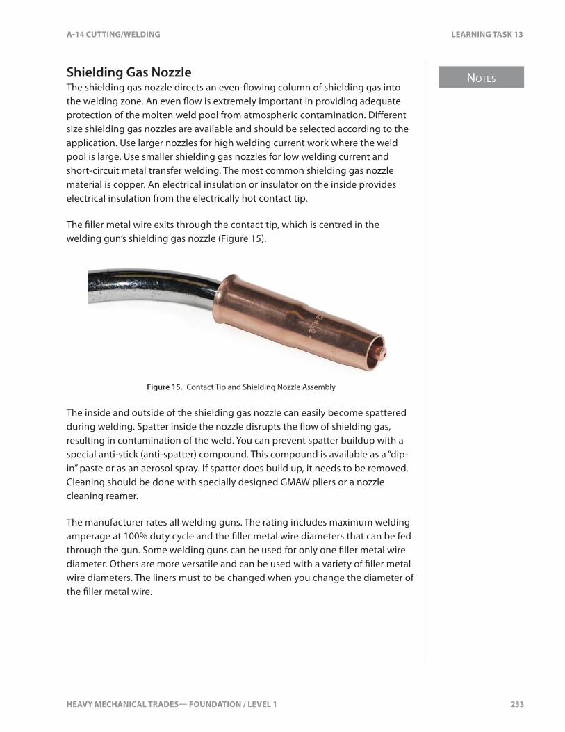
HEAVY MECHANICAL TRADES— FOUNDATION / LEVEL 1 233
NOTES
A-14 CUTTING/WELDING LEARNING TASK 13
Shielding Gas NozzleThe shielding gas nozzle directs an even-�owing column of shielding gas into the welding zone. An even �ow is extremely important in providing adequate protection of the molten weld pool from atmospheric contamination. Di�erent size shielding gas nozzles are available and should be selected according to the application. Use larger nozzles for high welding current work where the weld pool is large. Use smaller shielding gas nozzles for low welding current and short-circuit metal transfer welding. The most common shielding gas nozzle material is copper. An electrical insulation or insulator on the inside provides electrical insulation from the electrically hot contact tip.
The �ller metal wire exits through the contact tip, which is centred in the welding gun’s shielding gas nozzle (Figure 15).
Figure 15. Contact Tip and Shielding Nozzle Assembly
The inside and outside of the shielding gas nozzle can easily become spattered during welding. Spatter inside the nozzle disrupts the �ow of shielding gas, resulting in contamination of the weld. You can prevent spatter buildup with a special anti-stick (anti-spatter) compound. This compound is available as a “dip-in” paste or as an aerosol spray. If spatter does build up, it needs to be removed. Cleaning should be done with specially designed GMAW pliers or a nozzle cleaning reamer.
The manufacturer rates all welding guns. The rating includes maximum welding amperage at 100% duty cycle and the �ller metal wire diameters that can be fed through the gun. Some welding guns can be used for only one �ller metal wire diameter. Others are more versatile and can be used with a variety of �ller metal wire diameters. The liners must to be changed when you change the diameter of the �ller metal wire.
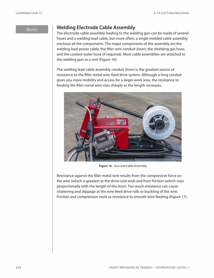
NOTES
234 HEAVY MECHANICAL TRADES— FOUNDATION / LEVEL 1
LEARNING TASK 13 A-14 CUTTING/WELDING
Welding Electrode Cable AssemblyThe electrode cable assembly leading to the welding gun can be made of several hoses and a welding lead cable, but more often, a single molded cable assembly encloses all the components. The major components of the assembly are the welding lead power cable, the �ller wire conduit (liner), the shielding gas hose, and the coolant water hose (if required). Most cable assemblies are attached to the welding gun as a unit (Figure 16).
The welding lead cable assembly conduit (liner) is the greatest source of resistance to the �ller metal wire-feed drive system. Although a long conduit gives you more mobility and access for a larger work area, the resistance to feeding the �ller metal wire rises sharply as the length increases.
Figure 16. Gun and Cable Assembly
Resistance against the �ller metal wire results from the compressive force on the wire (which is greatest at the drive-unit end) and from friction (which rises proportionally with the length of the liner). Too much resistance can cause chattering and slippage at the wire-feed drive rolls or buckling of the wire. Friction and compression work as resistance to smooth wire-feeding (Figure 17).
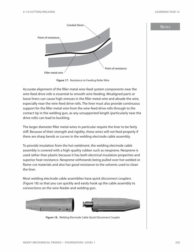
HEAVY MECHANICAL TRADES— FOUNDATION / LEVEL 1 235
NOTES
A-14 CUTTING/WELDING LEARNING TASK 13
Conduit (liner)
Point of resistance
Filler metal wirePoint of resistance
Figure 17. Resistance to Feeding Roller Wire
Accurate alignment of the �ller metal wire-feed system components near the wire-feed drive rolls is essential to smooth wire-feeding. Misaligned parts or loose liners can cause high stresses in the �ller metal wire and abrade the wire, especially near the wire-feed drive rolls. The liner must also provide continuous support for the �ller metal wire from the wire-feed drive rolls through to the contact tip in the welding gun, as any unsupported length (particularly near the drive rolls) can lead to buckling.
The larger diameter �ller metal wires in particular require the liner to be fairly sti�. Because of their strength and rigidity, these wires will not feed properly if there are sharp bends or curves in the welding electrode cable assembly.
To provide insulation from the hot weldment, the welding electrode cable assembly is covered with a high-quality rubber such as neoprene. Neoprene is used rather than plastic because it has both electrical insulation properties and superior heat resistance. Neoprene withstands being pulled over hot welded or �ame-cut materials and also has good resistance to the solvents used to clean the liner.
Most welding electrode cable assemblies have quick disconnect couplers (Figure 18) so that you can quickly and easily hook up the cable assembly to connections on the wire-feeder and welding gun.
Figure 18. Welding Electrode Cable Quick Disconnect Coupler
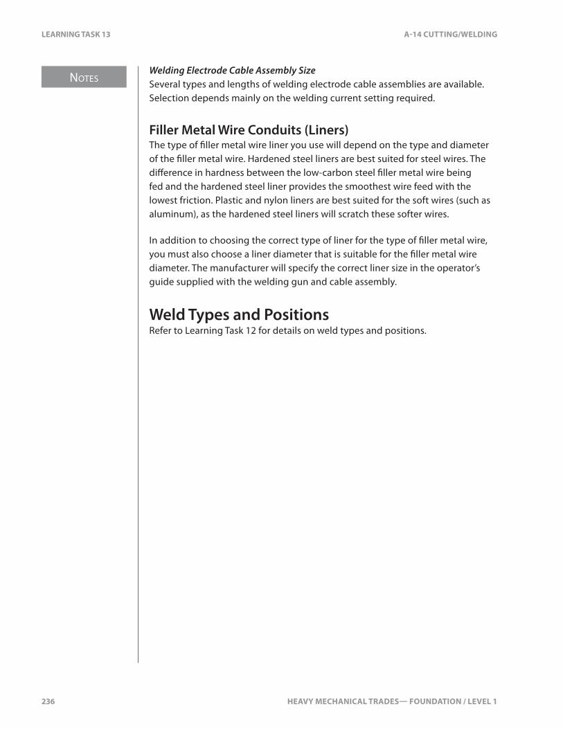
NOTES
236 HEAVY MECHANICAL TRADES— FOUNDATION / LEVEL 1
LEARNING TASK 13 A-14 CUTTING/WELDING
Welding Electrode Cable Assembly SizeSeveral types and lengths of welding electrode cable assemblies are available. Selection depends mainly on the welding current setting required.
Filler Metal Wire Conduits (Liners)The type of �ller metal wire liner you use will depend on the type and diameter of the �ller metal wire. Hardened steel liners are best suited for steel wires. The di�erence in hardness between the low-carbon steel �ller metal wire being fed and the hardened steel liner provides the smoothest wire feed with the lowest friction. Plastic and nylon liners are best suited for the soft wires (such as aluminum), as the hardened steel liners will scratch these softer wires.
In addition to choosing the correct type of liner for the type of �ller metal wire, you must also choose a liner diameter that is suitable for the �ller metal wire diameter. The manufacturer will specify the correct liner size in the operator’s guide supplied with the welding gun and cable assembly.
Weld Types and PositionsRefer to Learning Task 12 for details on weld types and positions.

HEAVY MECHANICAL TRADES— FOUNDATION / LEVEL 1 237
A-14 CUTTING/WELDING SELF TEST 13
SELF TEST 13
1. What is the main advantage of the GMAW and FCAW processes?
a. wide range of �ller metals available
b. low initial and operating costs
c. minimal training required for operators
d. high deposition rates (LT13, GMAW, GMAW-P, FCAW, and MCAW)
2. What set-up does the GMAW process normally use?
a. DCEP
b. DCEN
c. DC/AC
d. AC
3. What protects the arc from atmospheric contamination when GMAW?
a. �ux coating
b. shielding gas
c. oxygen
d. carbon dioxide

238 HEAVY MECHANICAL TRADES— FOUNDATION / LEVEL 1

HEAVY MECHANICAL TRADES— FOUNDATION / LEVEL 1 239
NOTES
A-14 CUTTING/WELDING LEARNING TASK 14
LEARNING TASK 14
Describe Air Arc Gouging
Air Carbon Arc CuttingThe air carbon arc process is one of several arc-cutting processes. It’s abbreviated as “CAC-A.” In the past, it was abbreviated as “AAC.” The CAC-A process is widely used because it can cut and gouge all types of ferrous and non-ferrous metals more quickly than �ame cutting.
CAC-A is considered to be a cutting process, but it does much more. CAC-A can do a partial cut, gouge, or wash o� a surface. This can prepare joints for welding, remove unwanted metal, remove weld faults, or remove bolts, pins, and other fasteners.
Principles of CAC-AAir carbon arc cutting works by melting the base metal with an electric arc (Figure 1). This arc is produced by a welding power source passing current through a carbon electrode held in a special holder. Jets of compressed air from holes in the lower jaw of the electrode holder blow the molten metal away to form a kerf or groove.
Air jets
Carbon electrode
Electrode holder
Figure 1. CAC-A Gouging

NOTES
240 HEAVY MECHANICAL TRADES— FOUNDATION / LEVEL 1
LEARNING TASK 14 A-14 CUTTING/WELDING
CAC-A can be used on any kind of metal because it uses the intense heat of the arc to melt the metal. CAC-A does not cut the base metal by oxidizing it, as the oxy-fuel gas processes do. Unlike the oxy-fuel gas cutting processes, CAC-A can be used on any material that conducts electricity.
Components of the CAC-AThe basic CAC-A system consists of a welding power source, an electrode holder, a carbon electrode, and a compressed air supply system (Figure 2). The power source can be any high-capacity welding power source that provides enough current.
Electrode holder
Air compressor Welding power source
Workpiece lead
Workpiece
Air line
Carbon electrode
Electrode leadGround clamp
– +
Figure 2. Typical CAC-A System
To strike the arc, simply touch the carbon electrode to the work piece in the same as you would for SMAW. The circuit is now closed (or complete) and the welding current �ows through the circuit. As the current crosses the arc, it creates tremendous heat. A small area of base metal just below the electrode melts.
The CAC-A electrode holder has small holes or ori�ces that direct compressed air at the cut to blow the molten metal out of the gouge or cut area. The electrode holder is commonly called a “gouging torch” (Figure 3).

HEAVY MECHANICAL TRADES— FOUNDATION / LEVEL 1 241
NOTES
A-14 CUTTING/WELDING LEARNING TASK 14
Carbon electrode
Air jet holes (orifices)Air control valve
Figure 3. Typical CAC-A Gouging Torch
Any standard welding power source, either AC or DC, can be used for CAC-A. It must be able to produce enough current for the size of the electrode.
Safe Work Practices for CAC-ACAC-A has additional safety hazards in addition to those for any arc welding process.
VentilationCAC-A is used to cut metals that are not usually cut with oxy-fuel gas. Many of these metals contain elements that produce toxic fumes when heated. Stainless steel, for example, contains chromium, which produces dangerous fumes when heated. Other metals, such as high-alloy steel and copper alloys, are also dangerous when heated.
You must wear a respirator when cutting any metals that contain chromium, zinc, copper, or nickel. Never use CAC-A to cut beryllium, cadmium, or lead. These metals produce extremely toxic fumes.
Heat from CAC-A can cause paint �nishes and industrial coatings to produce toxic fumes. Grind or scrape the surrounding gouge area before gouging. Use active ventilation and a respirator.
NoiseNoise levels from the compressed air used with CAC-A are very high. Wear ear protection (earplugs and/or earmu�s) when cutting with CAC-A. Ear protection will also prevent a stray spark from entering your ear canal and possibly perforating your eardrum. In extreme cases, infection from this kind of injury can cause complete hearing loss.
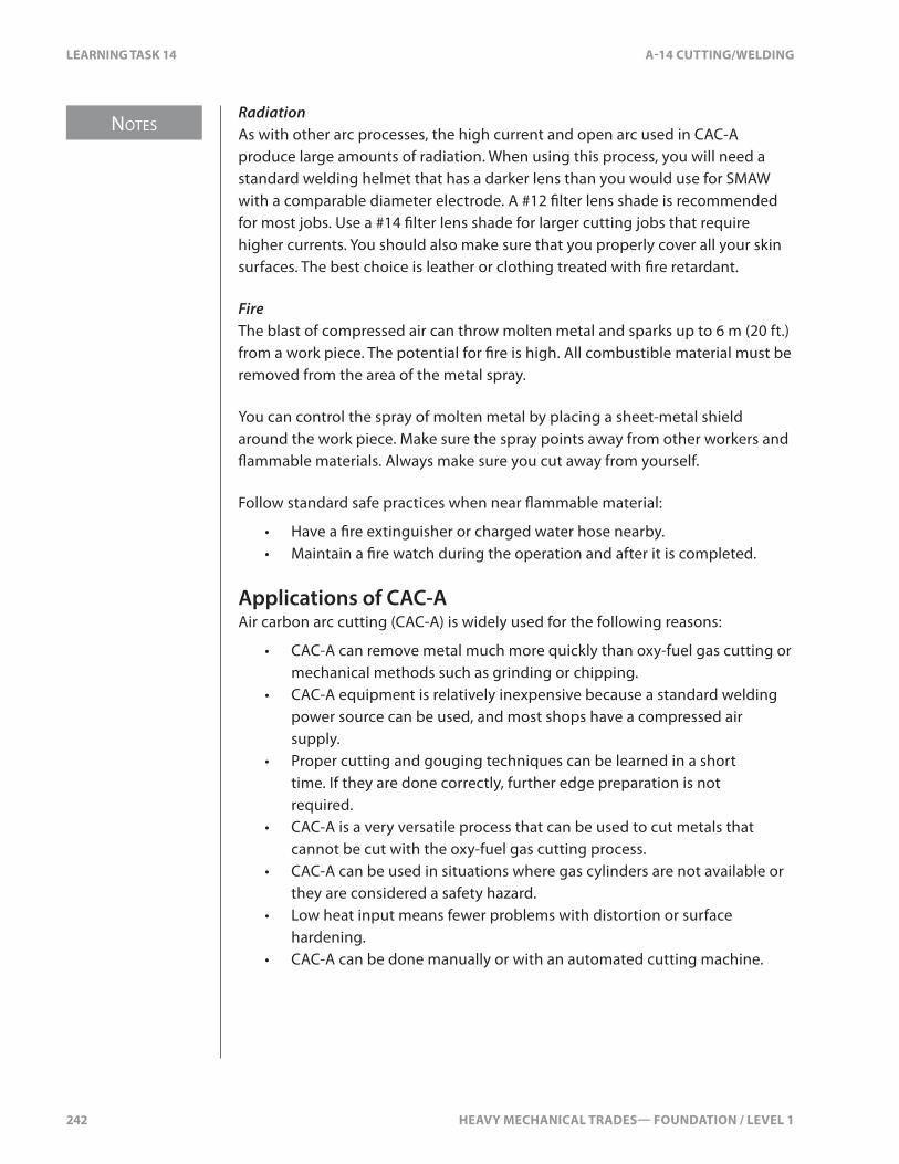
NOTES
242 HEAVY MECHANICAL TRADES— FOUNDATION / LEVEL 1
LEARNING TASK 14 A-14 CUTTING/WELDING
RadiationAs with other arc processes, the high current and open arc used in CAC-A produce large amounts of radiation. When using this process, you will need a standard welding helmet that has a darker lens than you would use for SMAW with a comparable diameter electrode. A #12 �lter lens shade is recommended for most jobs. Use a #14 �lter lens shade for larger cutting jobs that require higher currents. You should also make sure that you properly cover all your skin surfaces. The best choice is leather or clothing treated with �re retardant.
FireThe blast of compressed air can throw molten metal and sparks up to 6 m (20 ft.) from a work piece. The potential for �re is high. All combustible material must be removed from the area of the metal spray.
You can control the spray of molten metal by placing a sheet-metal shield around the work piece. Make sure the spray points away from other workers and �ammable materials. Always make sure you cut away from yourself.
Follow standard safe practices when near �ammable material:
• Have a �re extinguisher or charged water hose nearby.• Maintain a �re watch during the operation and after it is completed.
Applications of CAC-AAir carbon arc cutting (CAC-A) is widely used for the following reasons:
• CAC-A can remove metal much more quickly than oxy-fuel gas cutting or mechanical methods such as grinding or chipping.
• CAC-A equipment is relatively inexpensive because a standard welding power source can be used, and most shops have a compressed air supply.
• Proper cutting and gouging techniques can be learned in a short time. If they are done correctly, further edge preparation is not required.
• CAC-A is a very versatile process that can be used to cut metals that cannot be cut with the oxy-fuel gas cutting process.
• CAC-A can be used in situations where gas cylinders are not available or they are considered a safety hazard.
• Low heat input means fewer problems with distortion or surface hardening.
• CAC-A can be done manually or with an automated cutting machine.

HEAVY MECHANICAL TRADES— FOUNDATION / LEVEL 1 243
NOTES
A-14 CUTTING/WELDING LEARNING TASK 14
Manual CuttingFor most CAC-A jobs, you’ll use a manual torch. The equipment is versatile and portable, and the process can be done in the shop or on the job site.
Machine CuttingMachine cutting is more accurate than manual cutting. The cuts are straighter and cleaner than those produced manually. This is important when preparing a weld groove.
CAC-A cutting machines have a motorized carriage mounted on a track. They are similar to the machines used for OFC. These machines are portable and can be mounted in a vertical, horizontal, or overhead position.
On a semi-automatic machine, the electrode must be manually fed into the holder to produce the desired cut. The carriage moves along the track at a preset speed. The amperage and air volume are also preset. These semi-automatic machines are simple to operate and produce clean cuts.
Fully automatic machines feed the carbon electrode automatically. They’re used when you want even greater accuracy. One type of automatic machine uses a spring-loaded device that maintains a constant distance between the electrode and the work piece. This provides a uniform groove depth.
More sophisticated machines use a voltage-controlled electrode feed. This maintains a constant arc length and produces grooves with a depth tolerance of ± 0.6 mm (± 0.025 in.).
Uses of CAC-ACAC-A can be used to cut metals that cannot be cut well with oxy-fuel gas. These metals include stainless steel, aluminum, cast iron, nickel, and copper alloys. For example, CAC-A is used in re�neries and pulp mills where stainless steel pipe or other high-alloy steel pipe must be cut.
Except for certain metals, CAC-A is seldom used for cutting through metals because there are other processes that can make these cuts more smoothly and accurately. The CAC-A process is used much more widely for gouging and for metal removal.
When properly done, CAC-A gouged grooves are very clean, smooth, and suitable for welding with no further preparation (Figure 4). The groove itself is free of slag. Any minimal slag on the edge can be easily removed with a chipping hammer.
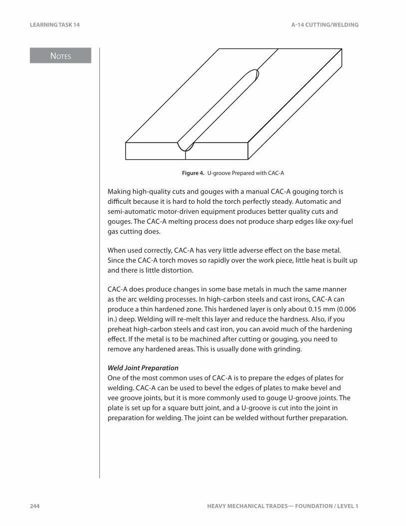
NOTES
244 HEAVY MECHANICAL TRADES— FOUNDATION / LEVEL 1
LEARNING TASK 14 A-14 CUTTING/WELDING
Figure 4. U-groove Prepared with CAC-A
Making high-quality cuts and gouges with a manual CAC-A gouging torch is di�cult because it is hard to hold the torch perfectly steady. Automatic and semi-automatic motor-driven equipment produces better quality cuts and gouges. The CAC-A melting process does not produce sharp edges like oxy-fuel gas cutting does.
When used correctly, CAC-A has very little adverse e�ect on the base metal. Since the CAC-A torch moves so rapidly over the work piece, little heat is built up and there is little distortion.
CAC-A does produce changes in some base metals in much the same manner as the arc welding processes. In high-carbon steels and cast irons, CAC-A can produce a thin hardened zone. This hardened layer is only about 0.15 mm (0.006 in.) deep. Welding will re-melt this layer and reduce the hardness. Also, if you preheat high-carbon steels and cast iron, you can avoid much of the hardening e�ect. If the metal is to be machined after cutting or gouging, you need to remove any hardened areas. This is usually done with grinding.
Weld Joint PreparationOne of the most common uses of CAC-A is to prepare the edges of plates for welding. CAC-A can be used to bevel the edges of plates to make bevel and vee groove joints, but it is more commonly used to gouge U-groove joints. The plate is set up for a square butt joint, and a U-groove is cut into the joint in preparation for welding. The joint can be welded without further preparation.
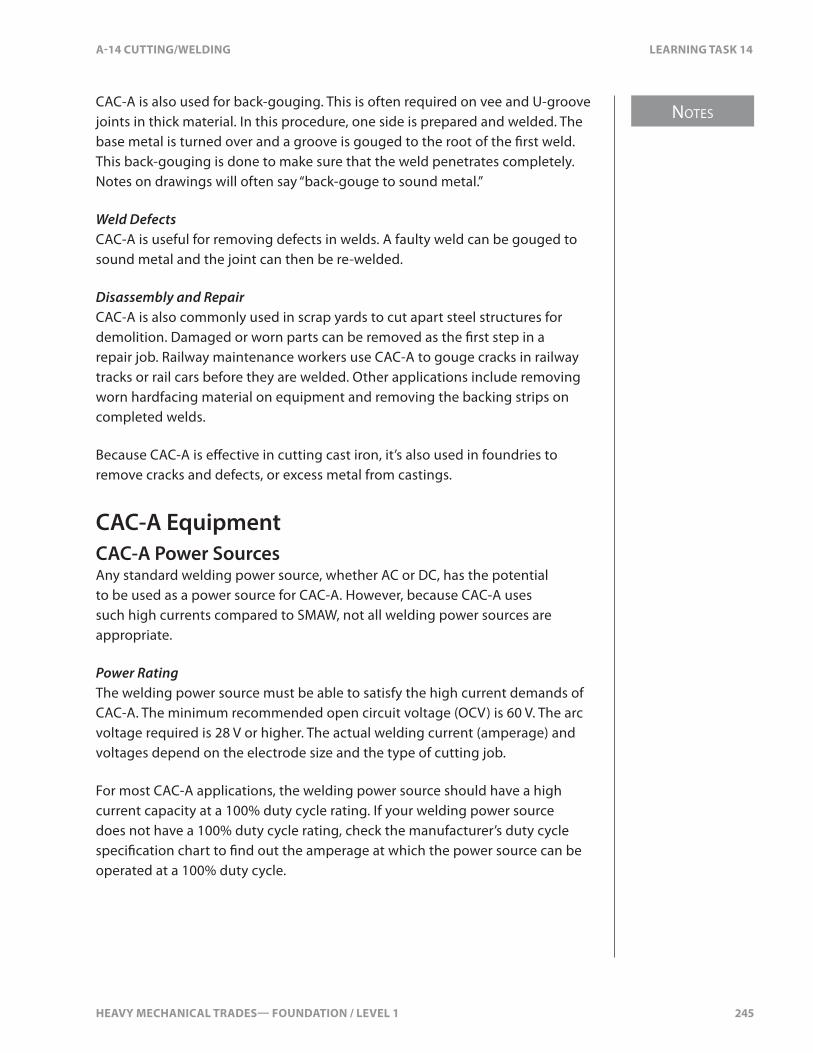
HEAVY MECHANICAL TRADES— FOUNDATION / LEVEL 1 245
NOTES
A-14 CUTTING/WELDING LEARNING TASK 14
CAC-A is also used for back-gouging. This is often required on vee and U-groove joints in thick material. In this procedure, one side is prepared and welded. The base metal is turned over and a groove is gouged to the root of the �rst weld. This back-gouging is done to make sure that the weld penetrates completely. Notes on drawings will often say “back-gouge to sound metal.”
Weld DefectsCAC-A is useful for removing defects in welds. A faulty weld can be gouged to sound metal and the joint can then be re-welded.
Disassembly and RepairCAC-A is also commonly used in scrap yards to cut apart steel structures for demolition. Damaged or worn parts can be removed as the �rst step in a repair job. Railway maintenance workers use CAC-A to gouge cracks in railway tracks or rail cars before they are welded. Other applications include removing worn hardfacing material on equipment and removing the backing strips on completed welds.
Because CAC-A is e�ective in cutting cast iron, it’s also used in foundries to remove cracks and defects, or excess metal from castings.
CAC-A EquipmentCAC-A Power SourcesAny standard welding power source, whether AC or DC, has the potential to be used as a power source for CAC-A. However, because CAC-A uses such high currents compared to SMAW, not all welding power sources are appropriate.
Power RatingThe welding power source must be able to satisfy the high current demands of CAC-A. The minimum recommended open circuit voltage (OCV) is 60 V. The arc voltage required is 28 V or higher. The actual welding current (amperage) and voltages depend on the electrode size and the type of cutting job.
For most CAC-A applications, the welding power source should have a high current capacity at a 100% duty cycle rating. If your welding power source does not have a 100% duty cycle rating, check the manufacturer’s duty cycle speci�cation chart to �nd out the amperage at which the power source can be operated at a 100% duty cycle.

NOTES
246 HEAVY MECHANICAL TRADES— FOUNDATION / LEVEL 1
LEARNING TASK 14 A-14 CUTTING/WELDING
Because carbon arc cutting and gouging use such high current, the welding power source should have overload protection in the output circuit. If you are not sure whether a particular welding power source is suitable for CAC-A, check the manufacturer’s speci�cations to see the rated duty cycles and if the machine is recommended for CAC-A.
Very few single-phase welding power sources produce enough current at a 100% duty cycle rating to be used for CAC-A. You are likely to permanently damage these units if you use them for gouging.
For the best results when doing CAC-A, you should use an industrial welding power source with the highest possible current capacity rated at a 100% duty cycle. The preferred choice is a large, three-phase transformer recti�er unit that has massive transformer windings and can take the extreme and violent surges in current. Similarly, if you use an engine-driven welding power source, it should have plenty of current capacity rated at a 100% duty cycle.
DC Versus AC Power SourcesBoth AC and DC welding power sources can be used for CAC-A. However, a DC welding power source is preferred for most CAC-A work because it produces a more stable arc and is more versatile. As for welding current e�ciency, DC produces more current than AC for the same arc voltage (AC is only about 70% as e�cient as DC).
For most CAC-A applications on carbon, low-alloy, and stainless steels, the polarity of the welding power source should be set to direct current electrode positive (DCEP).
For CAC-A on all cast irons, it’s recommended that AC or DCEN be used in combination with AC carbon electrodes. AC carbon electrodes are preferred as they have ingredients in them that let them work with AC. The end result of using AC carbon electrodes is a cleaner cut and less transfer of the carbon electrode to the base metal. Carbon transfer can be a nuisance during CAC-A on cast iron. However, in practice, most CAC-A on cast iron is done with DCEP using DC carbon electrodes and the carbon deposits are cleaned out as they build up.
On copper and nickel alloys, AC or DCEN should be used in combination with AC carbon electrodes. As an alternative, DCEP using DC carbon electrodes can be used on copper alloys.
Remember: For CAC-A on cast iron, copper alloys, or nickel alloys, AC produces cleaner cuts than DC. Also, when you are using AC current, you must use AC-rated carbon electrodes.

HEAVY MECHANICAL TRADES— FOUNDATION / LEVEL 1 247
NOTES
A-14 CUTTING/WELDING LEARNING TASK 14
The Electrode HolderThe hand-held CAC-A electrode holder, commonly called a “torch,” is very similar to a heavy-duty SMAW electrode holder (Figure 5). The major di�erence is the air jet ori�ces in the lower jaw of the holder that direct the compressed air jets at the molten base metal.
Clamp lever handle
Carbon electrode
Air control valve
GripheadAir jet holes (orifaces)
Figure 5. Manual CAC-A Torch
The air control valve on-o� button usually has a lock-open feature so you can keep the air �owing and still keep your hand in a comfortable position. The jaws are spring-loaded and hold the carbon electrode in place. A clamp lever handle opens the jaws.
The electrode holder has a small, circular griphead with a vee groove that �rmly grasps and locates the carbon electrode in relation to the air jet ori�ces. The griphead has two or three air jet ori�ces to direct the compressed air jet.
This griphead rotates 360 degrees so that you can adjust it to di�erent positions and directions, such as left to right or right to left (Figure 6).
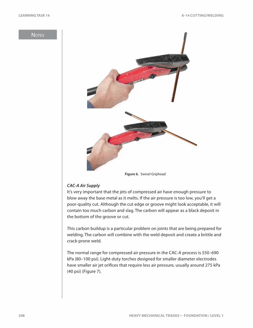
NOTES
248 HEAVY MECHANICAL TRADES— FOUNDATION / LEVEL 1
LEARNING TASK 14 A-14 CUTTING/WELDING
Figure 6. Swivel Griphead
CAC-A Air SupplyIt’s very important that the jets of compressed air have enough pressure to blow away the base metal as it melts. If the air pressure is too low, you’ll get a poor-quality cut. Although the cut edge or groove might look acceptable, it will contain too much carbon and slag. The carbon will appear as a black deposit in the bottom of the groove or cut.
This carbon buildup is a particular problem on joints that are being prepared for welding. The carbon will combine with the weld deposit and create a brittle and crack-prone weld.
The normal range for compressed air pressure in the CAC-A process is 550–690 kPa (80–100 psi). Light-duty torches designed for smaller diameter electrodes have smaller air jet ori�ces that require less air pressure, usually around 275 kPa (40 psi) (Figure 7).
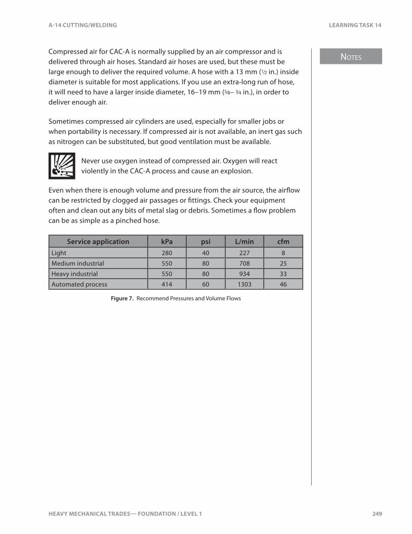
HEAVY MECHANICAL TRADES— FOUNDATION / LEVEL 1 249
NOTES
A-14 CUTTING/WELDING LEARNING TASK 14
Compressed air for CAC-A is normally supplied by an air compressor and is delivered through air hoses. Standard air hoses are used, but these must be large enough to deliver the required volume. A hose with a 13 mm (1⁄2 in.) inside diameter is suitable for most applications. If you use an extra-long run of hose, it will need to have a larger inside diameter, 16–19 mm (5⁄8– 3⁄4 in.), in order to deliver enough air.
Sometimes compressed air cylinders are used, especially for smaller jobs or when portability is necessary. If compressed air is not available, an inert gas such as nitrogen can be substituted, but good ventilation must be available.
Never use oxygen instead of compressed air. Oxygen will react violently in the CAC-A process and cause an explosion.
Even when there is enough volume and pressure from the air source, the air�ow can be restricted by clogged air passages or �ttings. Check your equipment often and clean out any bits of metal slag or debris. Sometimes a �ow problem can be as simple as a pinched hose.
Service application kPa psi L/min cfmLight 280 40 227 8
Medium industrial 550 80 708 25
Heavy industrial 550 80 934 33
Automated process 414 60 1303 46
Figure 7. Recommend Pressures and Volume Flows

250 HEAVY MECHANICAL TRADES— FOUNDATION / LEVEL 1
SELF TEST 14 A-14 CUTTING/WELDING
SELF TEST 14
1. Which metal should never be cut with CAC-A because it produces highly toxic fumes?
a. aluminum
b. lead
c. stainless steel
d. titanium
2. What is the purpose for the compressed air at the electrode holder?
a. clean the kerf
b. create the kerf
c. clean the electrode holder
d. remove the poisonous gasses
3. What is used to blow the molten metal away to form a kerf when carbon arc gouging?
a. compressed air
b. oxygen
c. nitrogen
d. carbon monoxide

A-15 JOB ACTION
COMPETENCY A-15PREPARE JOB ACTION
HEAVY MECHANICAL TRADES:LINE A—COMMON OCCUPATIONAL SKILLS

HEAVY MECHANICAL TRADES— FOUNDATION / LEVEL 1 253
Goals Preparing a proper job action plan will help all employees understand the shop expectations and procedures when starting any job.
When you have completed the Learning Tasks in this Competency, you will be able to:
• describe the procedures to prepare a job action• describe the risks of poor job action

254 HEAVY MECHANICAL TRADES— FOUNDATION / LEVEL 1
HEAVY MECHANICAL TRADES— FOUNDATION / LEVEL 1 255
NOTES
A-15 JOB ACTION LEARNING TASK 1
LEARNING TASK 1
Describe the Procedures to Prepare a Job Action
Access DocumentationWhen a job has been assigned, you’ll need to access and organize the documentation including:
• Locating the work order and reading the details for the work to be performed. This will include organizing the di�erent repairs on the equipment. Multiple repairs may con�ict with each other. For example, you may need to perform an engine tune-up as well as removing a transmission. These tasks will need to be prioritized.
• Locating and previewing the equipment work history. Checking the work history can provide you with valuable information for solving a problem, or repairing a re-occurring failure.
• Locating any product bulletins for the equipment. These bulletins can identify the cause of problems and detail the needed repairs.
• Locating and completing the job safety report prior to starting work. This will ensure the equipment is safe to work on.
• Locating the service repair manual and checking the manufacturer’s suggestions for safety and procedures.
• Locating and completing a hazard assessment report (if required)
Personal Protective EquipmentIt’s important that you have proper protective equipment when working in any heavy mechanical environment, including:
• hard hat• ear protection• safety glasses• face shield• work boots• work gloves• re�ective safety coveralls
Additionally, clean coveralls inspire con�dence in customers that you work in an e�cient and professional manner. You’re a representative of your company and maintaining a neat appearance can improve customer satisfaction.
NOTES
256 HEAVY MECHANICAL TRADES— FOUNDATION / LEVEL 1
LEARNING TASK 1 A-15 JOB ACTION
Environmental ConsiderationsYou must always consider the environment before starting any job. Environmental conditions can change and this can a�ect safety. One example involves the blocking of a equipment during winter. Cold, hard ground can turn to mud during a thaw and this may result in the equipment sliding o� the blocks.
Some important points to consider:
• cold weather—are heaters required?• hot weather—are shades needed?• rain—are covers required?• light—is additional lighting needed?• air quality— is ventilation required?• noise—is additional hearing protection needed?• space—is there su�cient room to perform the required tasks?• work site location—will you need extra clothing or supplies when
working in the �eld?• dangerous location—is the equipment located in a dangerous area such
as an avalanche zone?
Every time you go to a job site, you must be aware of any special pre-job action considerations.
Tools and EquipmentYou need to make a list of basic and specialty tools required for a job.
When working in the �eld, you may have to prepare and select the tools you’ll need while still at your shop. The work order will help you in determining exactly which tools you require. Tools that you must consider include:
• specialty hand tools• measuring instruments• specialty testing equipment such as scanners, multi-meters,
pressure gauges, and �ow meters• special pullers or pushers and their attachments• special blocking• special lifting equipment such as chains, cables shackles, and
lifting eyes
It’s important that you consider the preparation and organization of tools and equipment before starting a job.
HEAVY MECHANICAL TRADES— FOUNDATION / LEVEL 1 257
NOTES
A-15 JOB ACTION LEARNING TASK 1
PartsMany jobs will require that you order parts before commencing work. This is especially true for jobs conducted in the �eld. Remember that parts may be back-ordered and take several days for delivery. Organization is critical so that you have all the parts you need once you’re ready to start the job.
You should create an itemized list of all required parts. This will help you keep track of all parts you need, when they were ordered, where they were ordered from, and when they will be delivered.
Before ordering parts, make sure you have all the relevant information for the equipment such as the serial number, unit number, etc. This helps ensure that you order the correct part as well as making sure that the right part is delivered.

258 HEAVY MECHANICAL TRADES— FOUNDATION / LEVEL 1
SELF TEST 1 A-15 JOB ACTION
SELF TEST 1
1. What is the �rst thing that needs to be done when preparing a job action?
a. locate the tools and equipment
b. locate the personal protective equipment
c. review the environmental situations
d. review the documentation
2. You are asked to drive to a construction site and remove an engine from a machine. The crane is on site. What specialty tools might you collect at your shop?
a. specialty measuring instruments
b. specialty test equipment
c. specialty lifting equipment
d. specialty pullers
HEAVY MECHANICAL TRADES— FOUNDATION / LEVEL 1 259
NOTES
A-15 JOB ACTION LEARNING TASK 2
LEARNING TASK 2
Describe the Risks of Poor Job Action
Cost of Improper Job ActionThe cost of an improper job action can be many thousands of dollars.
Poor communication with your supervisor can lead to mistakes. Therefore, most repair shops will establish a job action plan. Failure to follow this job action plan may result in:
• working on the wrong equipment• working on the wrong component on the equipment• locating the equipment in the wrong area to perform repairs• using the wrong work order for the equipment• driving to the wrong job site• damage to shop equipment• injuries to shop sta�• ordering incorrect parts• frustration and embarrassment
Unhappy CustomersUnhappy customers will be di�cult to please once improper job action has occurred. Unhappy customers are reluctant to pay their bills and will scrutinize the job invoicing. Unhappy customers may request that you not work on their equipment in the future.
Lost BusinessIf poor job action results in added expense for a customer, there’s a risk of losing that customer’s business. Lost business a�ects everyone at the shop. Lay-o�s are more likely when there is insu�cient work.
Time ManagementRepair shops want to perform best practices when completing repairs. Each job is di�erent and may require more than one person to complete the work. Technicians are always looking for ways to do the work better and faster. E�ective time management is important to accomplish these goals.
Following a proper job action plan will minimize problems and help to improve time management.
NOTES
260 HEAVY MECHANICAL TRADES— FOUNDATION / LEVEL 1
LEARNING TASK 2 A-15 JOB ACTION
E�ciencyE�ciency is important when performing repairs. You must position the equipment/truck in a location that best suits the task at hand. Some considerations for this include:
• location of parts departments• location of cleaning areas• location of work benches• location of manuals• access to blocking equipment• proper storage areas for oil• location of chains, cables, bolt bins, and �re extinguishers• location of tools
It’s important that you make sure all these items are available and organized in a manner that will o�er the best e�ciency when you need them.
Damage to Components and EquipmentImproper job action (such as poor planning, poor equipment, or tight deadlines) can result in damage to vehicles or shop equipment as well as personal injury.
Damage may result from many actions including:
• improper location of equipment—trucks backing into other trucks• improper use of forklifts—backing into other equipment• improper use of blocking—falling equipment• improper use of lifting equipment—chains or slings breaking• improper use of pry bars or hammers—damage to components
HEAVY MECHANICAL TRADES— FOUNDATION / LEVEL 1 261
A-15 JOB ACTION SELF TEST 2
SELF TEST 2
1. What may result by using the wrong work order to perform engine repairs?
a. customer is happy, as he just received repairs he did not ask for
b. service manager is happy, as the repair shop got some extra work
c. service manager is unhappy as the repair shop will need to redo the job
d. service manager is happy, as he will need to discuss this with the customer
2. Who is primarily responsible to discuss poor job actions with unhappy customers?
a. the technician
b. service manager
c. shop foreman
d. shop union representative
3. Who may be asked to make up for lost time for damaged components when you use improper tools?
a. the technician
b. service manager
c. shop foreman
d. the apprentice working under you
4. You drive to a construction site and repair the wrong �nal drive on a crawler dozer. You read the work order wrong. You install all new bearings and seals. The cost is $15 000.00.
How should the repair shop approach this situation?
a. repair the proper �nal drive and charge the customer the additional costs
b. repair the proper �nal drive and only charge the customer the costs to repair that �nal drive
c. repair the proper �nal drive and do not charge the customer anything
d. repair the proper �nal drive and the service manager negotiates with the company for the wrong �nal drive repairs

262 HEAVY MECHANICAL TRADES— FOUNDATION / LEVEL 1

A-16 DIAGNOSTIC PROCEDURES
COMPETENCY A-16DESCRIBE DIAGNOSTIC PROCEDURES
HEAVY MECHANICAL TRADES:LINE A—COMMON OCCUPATIONAL SKILLS

HEAVY MECHANICAL TRADES— FOUNDATION / LEVEL 1 265
Goals When you have completed the Learning Tasks in this Competency, you will be able to:
• describe the importance of following a diagnostic procedure• describe diagnostic procedures used for troubleshooting

266 HEAVY MECHANICAL TRADES— FOUNDATION / LEVEL 1
HEAVY MECHANICAL TRADES— FOUNDATION / LEVEL 1 267
NOTES
A-16 DIAGNOSTIC PROCEDURES LEARNING TASK 1
LEARNING TASK 1
Describe the Importance of Following a Diagnostic Process
A diagnostic process is a sequence of events used to logically guide you through the steps needed to identify a particular problem. Most service manuals include a diagnostic section.
Cost of Improper DiagnosisImproper diagnosis can lead to excessive costs, both in shop labour and lost revenue due to equipment down-time. These costs must be absorbed by either the shop or the customer. Improper diagnosis may result from:
• not using a manual• not understanding diagnostic steps in a manual• following the wrong diagnostic steps• not having the correct diagnostic test equipment
Unhappy CustomersAlthough customers understand that mistakes can be made, they take a dim view when they’re the result of not following proper diagnostic processes. Unhappy customers are reluctant to allow you to repair their equipment if you’re known to disregard proper diagnostic procedures. It’s likely that such customers will seek other shops for future repair work. It can take years to regain a customer’s con�dence resulting in much lost business.
Time ManagementTime management is very important. Manufacturers design their manuals with time management as a priority. Some will list approximate times that a particular repair should take.
Your shop will usually give a customer a quote estimating the time it will take to complete the diagnostics. It’s important to stay within this time estimate where possible.
Customers appreciate it when you follow a service manual diagnostic sequence. It gives them con�dence that you’re following the proper procedure and not wasting time.

NOTES
268 HEAVY MECHANICAL TRADES— FOUNDATION / LEVEL 1
LEARNING TASK 1 A-16 DIAGNOSTIC PROCEDURES
E�ciencyUsing a diagnostic process leads to quicker repairs and happier customers. As you become familiar with using diagnostic processes, your diagnostic times will become faster. E�ciency will come with experience.
Once you’ve completed a diagnostic process, it’s worthwhile to re-check your work—you do not want to repair the wrong components.
Damage to ComponentsMost components require speci�c steps to disassemble, inspect, test, and re-assemble. Not following a proper diagnostic process may lead to damaged components. Damaging components during the diagnostic process can result in expensive repairs that have nothing to do with the original problem. This leads to frustrated and unhappy customers.

HEAVY MECHANICAL TRADES— FOUNDATION / LEVEL 1 269
A-16 DIAGNOSTIC PROCEDURES SELF TEST 1
SELF TEST 1
1. Why is it important to follow a diagnostic process?
a. because you were unable to talk with the operator
b. because you do not understand the system
c. because you are preventing lost time
d. because you do not understand the complaint

270 HEAVY MECHANICAL TRADES— FOUNDATION / LEVEL 1
HEAVY MECHANICAL TRADES— FOUNDATION / LEVEL 1 271
NOTES
A-16 DIAGNOSTIC PROCEDURES LEARNING TASK 2
LEARNING TASK 2
Describe General Diagnostic Procedures
Understand the SystemFamiliarity with a system is very important when you’re following diagnostic procedures. Whether it’s electrics, hydraulics, transmissions, or engines, you’ll need a detailed knowledge of these systems. Constant training is necessary to understand all the di�erent components on trucks and equipment. It’s advisable to read service manuals before starting diagnostic procedures.
Understand the ComplaintCorrectly communicating customer complaints is a major problem in the repair industry. The original customer complaint may pass through several people before you receive it. Miscommunication may result in you diagnosing the wrong problem. It’s important that there be su�cient information on the work order to direct you to the proper diagnostics.
You may receive a description of a problem by email, phone, text, fax, or on a piece of paper. It can be di�cult to understand the complaint with these methods of communication as they often do not give symptoms or operational irregularities.
Communicate with OperatorTalking directly with the operator will allow you to decipher the problem more e�ciently. Be sure to ask probing questions about the complaint:
• What are the symptoms?• When did it �rst start to show these symptoms?• Have the symptoms gotten worse over time?• Is the equipment making any unusual sounds?• Are there any unusual smells?• Is there any unusual vibration?• What do your dash gauges show?
Once you understand the complaint, you can focus on the area that requires operational tests and visual inspections.

NOTES
272 HEAVY MECHANICAL TRADES— FOUNDATION / LEVEL 1
LEARNING TASK 2 A-16 DIAGNOSTIC PROCEDURES
Operational TestWhen using diagnostic �ow charts (some companies refer to these as “trees”), you will have to perform operational tests as part of your diagnosis. The purpose of this is to con�rm the complaint and identify any other areas that need repairs.
When performing an operational test, it’s important to know the equipment’s limitations. It’s likely that you’ll have limited experience actually operating the equipment so you may need the operator to help you with the test.
Visual InspectionOnce you have con�rmed the complaint, you can begin the visual inspection. Despite the name, this may involve smelling, hearing, and feeling in addition to sight. Some tasks that you may perform include:
• listen for any unusual noises• inspecting linkages (binding or damage)• inspect �uid levels• inspecting for �uid leaks (oils, coolant, or fuel)• inspect �uids for colour, smell, and feel• inspect screens and magnets for contaminants• inspect �lters for contaminants
Determine Potential CausesOnce you’ve �nished the visual inspection, you should have enough information to make a list of potential causes. This list should be prioritized from the most likely to least likely. How you prioritize the list will also depend on how easy, or di�cult, the particular test is.
Your experience, combined with the troubleshooting guide, will direct you to test the most likely cause of the problem. Your list of potential causes should be included in the service report.
Test Potential CausesOnce you’ve determined the potential causes of a problem, you must test each hypothesis. This may require special testing equipment such as electronic scanners, electrical test equipment, hydraulic �ow meters, and hydraulic pressure gauges. It’s very important to follow the diagnostic guide as this can take considerable time.
The diagnostic guide in Figure 1 will help you narrow down a diesel engine with a black or grey smoke problems.

HEAVY MECHANICAL TRADES— FOUNDATION / LEVEL 1 273
A-16 DIAGNOSTIC PROCEDURES LEARNING TASK 2
BLACK OR DARK GREY SMOKE
SYMPTOM CAUSE ACTION TO TAKE COMMENTS
Smoke at high and medium speed under full load with engine quieter than normal
Pump timing retarded
Check and adjust the timing to speci�cations
Pump timing can only be wrong if installed improperly, timing advance failure, or loose mounting fasteners
Smoke at low and medium speed under full load with engine noisier than normal
Pump timing advanced
Check and adjust the timing to speci�cations
Pump timing can only be wrong if installed improperly, timing advance failure, or loose mounting fasteners
Smoke at high and medium speed under full load with loss of power
Injection nozzle discharge holes partially blocked
Clean or replace nozzles as necessary
Can be caused from dirt or water in the fuel
Smoke at high speed under full load
Air cleaner restricted
Clean or replace air cleaner
Service at more frequent intervals
Intermediate or pu�y smoke with white or bluish ting with engine knocking
Injection nozzles sticking intermittently
Clean, repair, or replace nozzles as necessary
Can be caused from dirt or water in the fuel
Smoke at low and medium speed under full load with hard start
Loss of compression from valves, rings, or other components
Check for engine overhaul, valve adjustments, or compression
May be caused from incorrect crankcase oil level
Figure 1. Diagnostic Guide
Figure 2 shows another example of a diagnostic guide, this one identifying steering problems. The guide identi�es potential causes of the problem, where to look, and how to repair it.
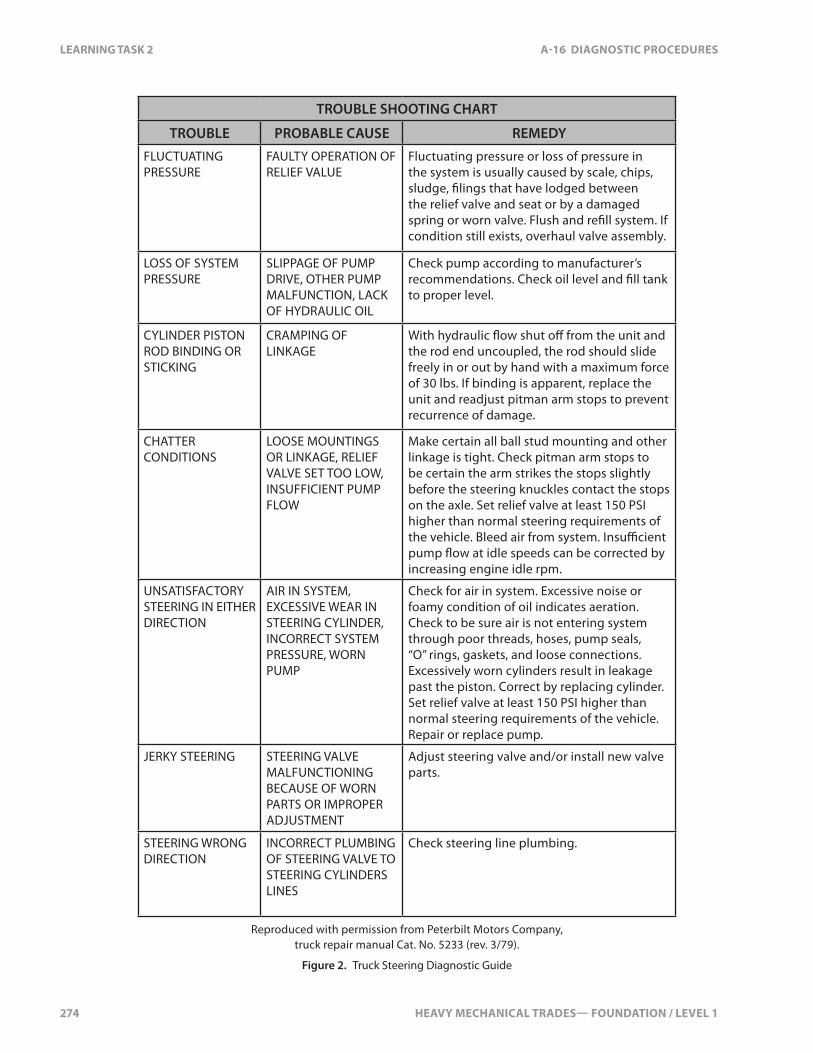
274 HEAVY MECHANICAL TRADES— FOUNDATION / LEVEL 1
LEARNING TASK 2 A-16 DIAGNOSTIC PROCEDURES
TROUBLE SHOOTING CHART
TROUBLE PROBABLE CAUSE REMEDY
FLUCTUATING PRESSURE
FAULTY OPERATION OF RELIEF VALUE
Fluctuating pressure or loss of pressure in the system is usually caused by scale, chips, sludge, �lings that have lodged between the relief valve and seat or by a damaged spring or worn valve. Flush and re�ll system. If condition still exists, overhaul valve assembly.
LOSS OF SYSTEM PRESSURE
SLIPPAGE OF PUMP DRIVE, OTHER PUMP MALFUNCTION, LACK OF HYDRAULIC OIL
Check pump according to manufacturer’s recommendations. Check oil level and �ll tank to proper level.
CYLINDER PISTON ROD BINDING OR STICKING
CRAMPING OF LINKAGE
With hydraulic �ow shut o� from the unit and the rod end uncoupled, the rod should slide freely in or out by hand with a maximum force of 30 lbs. If binding is apparent, replace the unit and readjust pitman arm stops to prevent recurrence of damage.
CHATTER CONDITIONS
LOOSE MOUNTINGS OR LINKAGE, RELIEF VALVE SET TOO LOW, INSUFFICIENT PUMP FLOW
Make certain all ball stud mounting and other linkage is tight. Check pitman arm stops to be certain the arm strikes the stops slightly before the steering knuckles contact the stops on the axle. Set relief valve at least 150 PSI higher than normal steering requirements of the vehicle. Bleed air from system. Insu�cient pump �ow at idle speeds can be corrected by increasing engine idle rpm.
UNSATISFACTORY STEERING IN EITHER DIRECTION
AIR IN SYSTEM, EXCESSIVE WEAR IN STEERING CYLINDER, INCORRECT SYSTEM PRESSURE, WORN PUMP
Check for air in system. Excessive noise or foamy condition of oil indicates aeration. Check to be sure air is not entering system through poor threads, hoses, pump seals, “O” rings, gaskets, and loose connections. Excessively worn cylinders result in leakage past the piston. Correct by replacing cylinder. Set relief valve at least 150 PSI higher than normal steering requirements of the vehicle. Repair or replace pump.
JERKY STEERING STEERING VALVE MALFUNCTIONING BECAUSE OF WORN PARTS OR IMPROPER ADJUSTMENT
Adjust steering valve and/or install new valve parts.
STEERING WRONG DIRECTION
INCORRECT PLUMBING OF STEERING VALVE TO STEERING CYLINDERS LINES
Check steering line plumbing.
Reproduced with permission from Peterbilt Motors Company, truck repair manual Cat. No. 5233 (rev. 3/79).
Figure 2. Truck Steering Diagnostic Guide

HEAVY MECHANICAL TRADES— FOUNDATION / LEVEL 1 275
NOTES
A-16 DIAGNOSTIC PROCEDURES LEARNING TASK 2
System Component IsolationOnce you’ve used the test equipment and isolated the component, you’ll follow the diagnostic guide to complete the repair.
When you’ve completed the repair, you’ll need to re-test the equipment to make sure that it has been �xed correctly and that there are no other problems. Re-testing removes any doubt concerning your diagnosis and con�rms that the complaint has been addressed.

276 HEAVY MECHANICAL TRADES— FOUNDATION / LEVEL 1
SELF TEST 2 A-16 DIAGNOSTIC PROCEDURES
SELF TEST 2
1. What is the �rst item in performing diagnostic procedures?
a. talk with the operator
b. perform an operational test
c. perform the visual inspection
d. know the system
2. What is the purpose for the operational test?
a. get familiar with the machine
b. con�rm the complaint
c. test your conclusions
d. perform visual tests
3. Why is it important to communicate with the operator?
a. they know the machine operation and complaint
b. they can help you when you perform the operational test
c. they will show you where to inspect
d. they know the machine systems and subsystems

HEAVY MECHANICAL TRADES— FOUNDATION / LEVEL 1 277
NOTES
A-16 DIAGNOSTIC PROCEDURES LEARNING TASK 3
LEARNING TASK 3
Describe the Importance of Following Manufacturer’s Diagnostic Procedures
Time SavingThe main reason for following a manufacturer’s procedures is to reduce the time it takes to repair equipment. Machinery produced for the heavy mechanical industry use computerized systems for the operation of the engine, hydraulics, steering, and controls. With such complex systems, it’s important to follow the speci�c manufacturer’s diagnostic procedures.
Following diagnostic charts will result in less time spent identifying the cause of a problem. Using a computer can also assist in determining the problematic area. An example is the electronic injectors on a diesel engine. By checking the electronic measurement of the injector with the aid of a computer reader, you’ll have an idea of what’s going on with the injection system. The manufacturer’s diagnostic manuals will give the needed speci�cations that will help with the diagnosis.
Warranty RequirementsWhen working for a dealership or distributor, the factory will require you to follow their diagnostic procedures for warranty purposes. By following the diagnostic charts, you’re removing all doubt as to what has occurred with the equipment. You’ll report back to the factory with your �ndings. The results are needed for warranty consideration which will determine who must pay for the repairs.
Diagnosis May Not Be Possible Any Other WayEquipment and components may be manufactured in such a way that following a manufacturer’s diagnostic chart is the only way to identify a problem. This is especially true due to the computerization of equipment which makes traditional techniques impractical with modern machinery. Diagnostic charts and computers are required to access the electronics in order to generate diagnostic codes or perform diagnostic functions.

278 HEAVY MECHANICAL TRADES— FOUNDATION / LEVEL 1
SELF TEST 3 A-16 DIAGNOSTIC PROCEDURES
SELF TEST 3
1. Why is it important to follow a manufacturer’s diagnostic procedure?
a. help communicate with the operator
b. help understand the complaint
c. help meet warranty requirements
d. help list the possible conclusions

HEAVY MECHANICAL TRADES— FOUNDATION / LEVEL 1 279
NOTES
A-16 DIAGNOSTIC PROCEDURES LEARNING TASK 4
LEARNING TASK 4
Describe the Importance of Failure Analysis
Failure analysis is the process by which you determine why a problem occurred.
Repeat FailureThe main bene�ts of failure analysis are to ensure that a problem does not re-occur and to discover if a part is defective (defective parts will usually be covered under warranty). By identifying the cause of a problem, you decrease the chance of it happening again. Repeated failures are costly to owners and equipment down-time is a large expense for companies. Your goal as a technician is to diagnose the problem quickly and accurately to reduce repeated failures.
Failure analysis may include examining and identifying causes of:
• engine failures• clutch failures• shaft failures• transmission failures• di�erential failures• �nal drive failures• hydraulic failures• �uid contaminations
Each time components are disassembled, you’ll need to isolate any causes of failures.
Extend LifeFailure analysis can also reduce the possibility of future problems. One prime area of reducing failure is the use of oil analysis. By checking for metal content in oil, problems can be averted, costs can be reduced, and the life of components can be extended.

NOTES
280 HEAVY MECHANICAL TRADES— FOUNDATION / LEVEL 1
LEARNING TASK 4 A-16 DIAGNOSTIC PROCEDURES
CostThe cost of performing failure analysis is very low compared to the cost of performing future repairs. Fluid failure analysis is particularly cheap and helps maintain a �le history for the equipment.
You may also need to take photos or �ll out documentation to support your failure analysis. This will become part of the record documenting the reason why a component failed.
Customer SatisfactionCustomers are pleased when failure analysis prevents further repairs and equipment down-time.
Failure analysis is a very subjective area and it can take years to acquire the knowledge needed to have an informed opinion on why things fail. When analyzing why things fail, use all available resources—your conclusion a�ects other issues, the most important being customer satisfaction.

HEAVY MECHANICAL TRADES— FOUNDATION / LEVEL 1 281
A-16 DIAGNOSTIC PROCEDURES SELF TEST 4
SELF TEST 4
1. What is the primary purpose for failure analysis?
a. prevent repeat failures
b. meet warranty requirements
c. provide proof of failure
d. extend service life

282 HEAVY MECHANICAL TRADES— FOUNDATION / LEVEL 1
A-17 EMPLOYM
ENT
COMPETENCY A-17PREPARE FOR EMPLOYMENT
HEAVY MECHANICAL TRADES:LINE A—COMMON OCCUPATIONAL SKILLS
HEAVY MECHANICAL TRADES— FOUNDATION / LEVEL 1 285
Goals Heavy Mechanical Trades training includes four di�erent mechanical trades:
• Heavy Duty Equipment Technician• Truck and Transport Mechanic• Transport Trailer Technician• Diesel Engine Mechanic
Heavy Duty Equipment Technician, Truck and Transport Mechanic, and Transport Trailer Technician are Red Seal Interprovincial recognized. Diesel Engine Mechanic is a Provincial Certi�cate of Trade Quali�cation for BC.
All four trades have an apprenticeship which provides you the opportunity to be paid and learn on the job, as well as receiving technical training at one of the province’s training providers. The types of equipment and vehicles you will work on will vary depending on which trade and repair facility you work for. It may range from very large mining equipment to highway tractor trailer units to small skid steer units to diesel engines. The type of business you will be employed at could be a small shop with a few employees, or an original equipment manufacturer with several employees, or a large company with several hundred employees. The environment you work in could be in a shop, or outside in the weather, or in a shop underground at a mine, or in the �eld working out of a service truck. There’s legislation that describes working standards designed to protect you as an employee, and the environment you work in. You may be employed at a union or non-union shop—both have advantages and disadvantages. Employers are looking for workers with good work ethics and attributes. You must show a potential employer that you have something they desire and need. Writing a proper resume that showcases your talents is critical to �nding the right job. When interviewing for a job, you must be prepared to demonstrate that you’re competent and would be an asset for the company. The job you’re hired for must work for both you and the employer.

286 HEAVY MECHANICAL TRADES— FOUNDATION / LEVEL 1
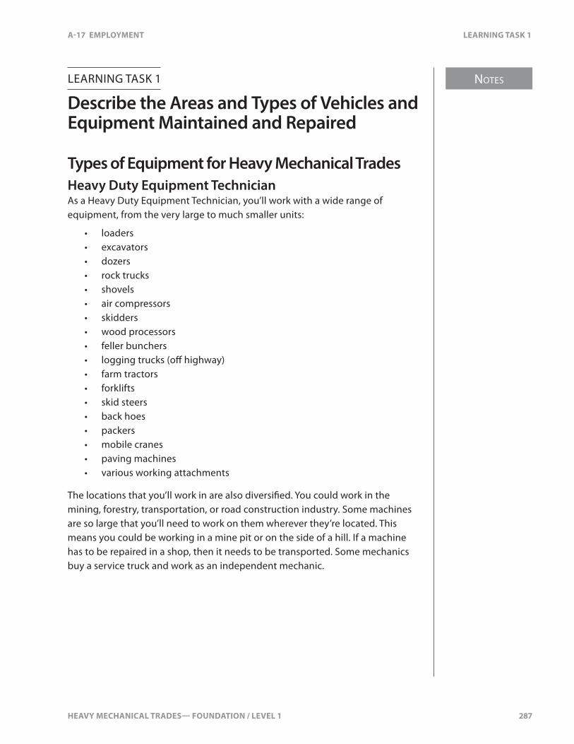
HEAVY MECHANICAL TRADES— FOUNDATION / LEVEL 1 287
NOTES
A-17 EMPLOYMENT LEARNING TASK 1
LEARNING TASK 1
Describe the Areas and Types of Vehicles and Equipment Maintained and Repaired
Types of Equipment for Heavy Mechanical TradesHeavy Duty Equipment TechnicianAs a Heavy Duty Equipment Technician, you’ll work with a wide range of equipment, from the very large to much smaller units:
• loaders• excavators• dozers• rock trucks• shovels• air compressors• skidders• wood processors• feller bunchers• logging trucks (o� highway)• farm tractors• forklifts• skid steers• back hoes• packers• mobile cranes• paving machines• various working attachments
The locations that you’ll work in are also diversi�ed. You could work in the mining, forestry, transportation, or road construction industry. Some machines are so large that you’ll need to work on them wherever they’re located. This means you could be working in a mine pit or on the side of a hill. If a machine has to be repaired in a shop, then it needs to be transported. Some mechanics buy a service truck and work as an independent mechanic.

NOTES
288 HEAVY MECHANICAL TRADES— FOUNDATION / LEVEL 1
LEARNING TASK 1 A-17 EMPLOYMENT
The types of jobs you’ll perform as a Heavy Duty Equipment Technician range from the very simple to the very complex. Servicing a machine includes greasing, oil and �lter changes, adjustments, and simple repairs. Diagnosing a machine requires understanding how the system works, understanding the complaint or problem, and following diagnostic procedures. Repairing a machine includes replacing, adjusting, and even rebuilding of systems or components.
Truck and Transport MechanicAs a Truck and Transport Mechanic, you’ll work mainly on trucks and trailer units:
Trucks:• single axle• tandem axle• tri-drive• dump truck (gravel truck)• logging• highway tractor• concrete mixer• van body• crane• garbage• tow truck• school bus• transit bus• coach
Trailers:• highboy• chip• drop deck• van• load bed• logging• dump• refrigeration unit
Truck and Transport Mechanics work in the service industry, forestry, construction, and mining. You’ll usually work in a shop, which can either be on-site or at a separate facility. Since trucks are relatively easy to tow, they’re usually taken to a shop for major repairs, but �eld-work is sometimes necessary. Some mechanics choose to buy a service truck and work as an independent mechanic.

HEAVY MECHANICAL TRADES— FOUNDATION / LEVEL 1 289
NOTES
A-17 EMPLOYMENT LEARNING TASK 1
The types of jobs you’ll perform range from servicing to diagnosing to overhauling. Servicing includes checking oil levels, greasing, oil and �lter changes, and minor repairs. Diagnosis includes understanding complex electronic system, following testing procedures and understanding the results. Repairs include replacing, adjusting, and rebuilding. In recent years, a greater emphasis has been placed on replacing components rather than rebuilding them.
Transport Trailer TechnicianAs a Transport Trailer Technician, you’ll work mainly with trailer units:
• semi• highboy• dump• refrigeration• low bed• chip• logging• van
Transport Trailer Technicians work in the service industry, forestry, construction, and mining. The work is usually done in a shop since trailers are easily transported. Service work includes greasing, adjustments, and minor repairs. Diagnosis includes understanding how the system works, understanding the complaint or problem, and following diagnostic procedures. Repairs include replacement, adjustments, and rebuilding systems or components. Electronically controlled systems have become much more common in the past few years.
Diesel Engine MechanicAs a Diesel Engine Mechanic, you’ll work on diesel engines from the truck, heavy equipment, or marine industries. Most of work is done in a shop, but some �eld work is also required. The engines can range from a small 3-cylinder engine to a large V16. Most Diesel Engine Mechanics work for a shop that specializes in the repair and overhaul of diesel engines. Servicing includes adjustments, and oil and �lter changes. Diagnosis involves understanding the engine and electronic control systems, and following diagnostic procedures. Repairs include replacement, adjusting, and overhauling of complete diesel engines. Diesel engines have advanced electronic control systems controlling the engine and after treatment systems.

NOTES
290 HEAVY MECHANICAL TRADES— FOUNDATION / LEVEL 1
LEARNING TASK 1 A-17 EMPLOYMENT
Heavy Mechanical TradesIn addition to the speci�c trades, you will often be required to work on your own shop equipment and vehicles. This may include items such as the shop pick-up or service truck, shop forklifts, or even chainsaws.
HEAVY MECHANICAL TRADES— FOUNDATION / LEVEL 1 291
A-17 EMPLOYMENT SELF TEST 1
SELF TEST 1
1. What trade are rock trucks?
a. truck and transport mechanic
b. transport trailer technician
c. diesel engine mechanic
d. heavy duty equipment technician
2. What trade are gravel trucks?
a. truck and transport mechanic
b. transport trailer technician
c. diesel engine mechanic
d. heavy duty equipment technician
3. What trade focuses on diesel engine repairs?
a. truck and transport mechanic
b. transport trailer technician
c. diesel engine mechanic
d. heavy duty equipment technician

292 HEAVY MECHANICAL TRADES— FOUNDATION / LEVEL 1
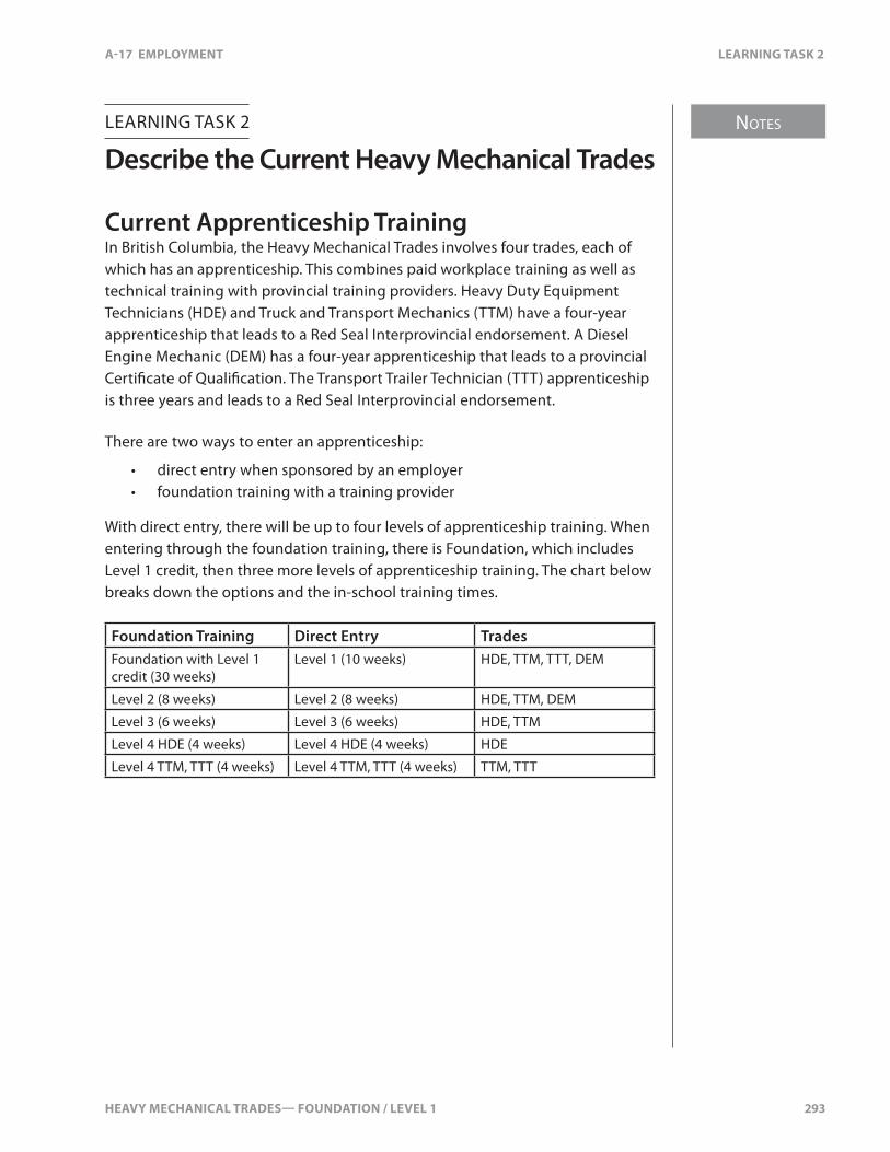
HEAVY MECHANICAL TRADES— FOUNDATION / LEVEL 1 293
NOTES
A-17 EMPLOYMENT LEARNING TASK 2
LEARNING TASK 2
Describe the Current Heavy Mechanical Trades
Current Apprenticeship TrainingIn British Columbia, the Heavy Mechanical Trades involves four trades, each of which has an apprenticeship. This combines paid workplace training as well as technical training with provincial training providers. Heavy Duty Equipment Technicians (HDE) and Truck and Transport Mechanics (TTM) have a four-year apprenticeship that leads to a Red Seal Interprovincial endorsement. A Diesel Engine Mechanic (DEM) has a four-year apprenticeship that leads to a provincial Certi�cate of Quali�cation. The Transport Trailer Technician (TTT) apprenticeship is three years and leads to a Red Seal Interprovincial endorsement.
There are two ways to enter an apprenticeship:
• direct entry when sponsored by an employer• foundation training with a training provider
With direct entry, there will be up to four levels of apprenticeship training. When entering through the foundation training, there is Foundation, which includes Level 1 credit, then three more levels of apprenticeship training. The chart below breaks down the options and the in-school training times.
Foundation Training Direct Entry TradesFoundation with Level 1 credit (30 weeks)
Level 1 (10 weeks) HDE, TTM, TTT, DEM
Level 2 (8 weeks) Level 2 (8 weeks) HDE, TTM, DEM
Level 3 (6 weeks) Level 3 (6 weeks) HDE, TTM
Level 4 HDE (4 weeks) Level 4 HDE (4 weeks) HDE
Level 4 TTM, TTT (4 weeks) Level 4 TTM, TTT (4 weeks) TTM, TTT
NOTES
294 HEAVY MECHANICAL TRADES— FOUNDATION / LEVEL 1
LEARNING TASK 2 A-17 EMPLOYMENT
In addition to technical training, you must accumulate workplace hours. Heavy Duty Equipment Technicians and Truck and Transport Mechanics must work a minimum of 6000 hours. Diesel Engine Mechanics have to work a minimum of 4500 hours. Transport Trailer Technicians have to work approximately 5000 hours prior to �nal certi�cation. At the end of your apprenticeship, you need the following in order to become certi�ed in your trade:
• completion of all technical training• completion of all level exams• completion of competency log book• completion of all workplace hours• completion of the �nal exam (Red Seal or Certi�cate of Quali�cation)• sign-o� by employer
Physical and Mental RequirementsIf you’re considering employment in the Heavy Mechanical Trades, you should recognize that there are a number of qualities that will enhance your potential for success.
Being in good health and having physical agility and strength is an advantage to a mechanic. Repairs to vehicles are made above, below, and inside equipment. At times, you’ll have to work in awkward positions for extended periods. Good hearing is essential for safety reasons as well as to diagnose knocks, squeaks, or rattles. Good eyesight is important for the examination of parts to determine their condition and make �ne adjustments. Since mechanics use their hands extensively, good manual dexterity is also required.
Your success as a mechanic requires that you have mechanical aptitude. This will allow you to picture in your mind the position and shape of objects and detect di�erences in the shape, size, and detail of objects or of pictorial material. Mechanical aptitude shows an ability to think through problems relating to objects and their relationship to other objects or devices. It also implies a high level of hand-eye coordination and an ability to manipulate objects, even small ones, with speed and accuracy.
A career as a Heavy Mechanical Trades mechanic requires that you have mechanical interests. These interests will show themselves in your preference for dealing with mechanical systems and objects. Your success in the mechanical trades requires that you be able to read and understand technical papers and service manuals with ease. You also need to be a problem solver, understanding the complete system and then diagnosing the problem.
HEAVY MECHANICAL TRADES— FOUNDATION / LEVEL 1 295
NOTES
A-17 EMPLOYMENT LEARNING TASK 2
Mechanics have to accept that they will get dirty during the day. Pressure-washing, parts washing, and working in dirty conditions are all part of the job and you have to be ready for that.
As a mechanic, you may end up working in a wide variety of settings with other people. If you are an e�ective listener, are courteous and patient, and enjoy a professional activity that brings you into regular contact with others, you are likely well-suited for these mechanical trades. As well, the technical sophistication and precision of the mechanics’ trades make skills in e�ective communication important.
296 HEAVY MECHANICAL TRADES— FOUNDATION / LEVEL 1
SELF TEST 2 A-17 EMPLOYMENT
SELF TEST 2
1. What are the total weeks of direct entry in-school apprenticeship training for TTT?
a. 4 weeks
b. 10 weeks
c. 14 weeks
d. 34 weeks
2. How many weeks in-school third year training for DEM?
a. 0 weeks
b. 4 weeks
c. 6 weeks
d. 8 weeks
HEAVY MECHANICAL TRADES— FOUNDATION / LEVEL 1 297
NOTES
A-17 EMPLOYMENT LEARNING TASK 3
LEARNING TASK 3
Describe the Range of Working Conditions
Job OpportunitiesUpon entering the Heavy Mechanical Trades, you’ll �nd many opportunities. Resources such as coal, copper, gasoline, natural gas, and wood products are in demand. Getting them from the ground to the end user depends on equipment and vehicles—jobs are available throughout the process from start to �nish. Pay scales and hours of work will vary as will the work environment and the quality of work.
LocationHeavy mechanical jobs are available from one end of the province to the other. Mines, both open pit and underground, need mechanics to keep their equipment and vehicles moving in extreme conditions. Mining coal, copper, gold, and silver requires many pieces of equipment that require regular servicing and repairs. Forestry requires equipment to cut trees, move them to a truck, and then will carry the logs to a saw mill for processing. Wood chips are then transported to a pulp mill to make paper. Gasoline, diesel, and propane are carried from a bulk plant to �lling stations. All of these methods of transportation require mechanics to service and repair equipment and vehicles.
You may work in a shop on equipment and vehicles that are brought in by customers. You may travel daily to a mine to work in the on-site shop or in the �eld. You may travel by plane and stay on-site for one or two weeks at a time before returning home. You might work out of your own service truck repairing equipment for your clients. The locations for work in BC are endless.
Advancement and SpecializationWhen you get your �rst job as a mechanic, you’ll be an apprentice. Subsequently, you’ll learn the trade from co-workers and technical training over the following years. You will then become a journeyperson. As you work and gather more and more knowledge, you’ll become more valuable to your company—they’ve invested time and money in you. After time, there may be opportunities for advancement to other positions. You may become a lead-hand and look after a work shift making work orders or supervising other mechanics. You may progress to a foreman who supervises a shop and all the mechanics. You may then become a service manager, responsible for an entire mechanical shop and all mechanical sta�. You may even become a branch manager, looking after the
NOTES
298 HEAVY MECHANICAL TRADES— FOUNDATION / LEVEL 1
LEARNING TASK 3 A-17 EMPLOYMENT
operation of an entire business: parts, sales, and service. Other opportunities include becoming a service representative for an original equipment manufacturer. After years of service, you could also become an instructor at a private trainer or a provincial training provider. Some mechanics choose to remain at one position in a company, but are still very valuable.
You may become a specialized mechanic. You could become the engine, gear, hydraulic, or electrical expert at a shop. By investing resources in you, you become very e�cient at your job, making them more money as well as keeping their customers happy.
Types of Employment OpportunitiesThere are many types of employment opportunities depending on your preferences. You may be hired by someone who has a �eet of equipment or vehicles. A dealership may hire you to work on one brand of vehicle or you could be hired by a shop that will work on all types of equipment. You may start with one type of employer and move to another gaining valuable experience from each.
Pay ScalesPay scale varies depending on where you’re employed. When you �rst start your apprenticeship, you will usually be paid approximately 50–60% of a journeyperson’s wages. Then, every six months you may receive a 5% pay increase. By the time you’re a fourth-year apprentice, you should be making close to the journeyperson’s wages. A journeyperson’s wage ranges from $30/hr to $40/hr or more, depending on the speci�c location. In addition to wages, there is usually a package with health bene�ts, boot and tool allowance, retirement pension, and vacation pay. Each employer will have a di�erent pay and wage package. Typically, a mechanic in the Heavy Mechanical Trades is well-paid.
Hours of WorkThe traditional work week is eight hours a day, �ve days a week which adds up to 40 hours each week. However, there are many alternatives to the traditional 40-hour work week. Some workplaces work four ten-hour days with a rotation that changes the days you work from week to week. Others use a twelve-hour day. Some have three twelve-hour shifts a week that rotates. Some shops work two twelve-hour day shifts followed by twenty-four hours o� and then two twelve-hour night shifts. If you’re �ying into a camp and working for two or three weeks straight, you might be working at least twelve hours a day. There are all types of hours and shifts depending on where you’re working. There is also overtime, which is work done in addition to your regular hours. You’re usually paid extra for overtime hours.
HEAVY MECHANICAL TRADES— FOUNDATION / LEVEL 1 299
NOTES
A-17 EMPLOYMENT LEARNING TASK 3
Working EnvironmentWorking environments in the Heavy Mechanical Trades will vary considerably depending on the workplace. When working in a shop atmosphere, you’re normally protected from the cold, heat, wind, and dust but you may also work in a yard or conduct �eld repairs. When working in the �eld, you must consider the conditions. Is it hot and dusty? Pouring rain? Extremely cold? You must be prepared for whatever mother nature throws at you. If it’s very cold, a portable heater and tarp can be used to allow you to work. Equipment and vehicles are often dirty and dusty and you may have to work on them without cleaning them completely. A workplace may be noisy, requiring that you protect yourself from hearing loss. When working alone, you must take extra precautions to prevent injury. There may be moving machinery in the area in which you are working which must be taken into consideration.
Quality ControlIn today’s Heavy Mechanical Trades, there’s no room for mistakes or come-backs. The cost of parts and labour are expensive, as is the cost to the customer in lost revenue. Mistakes can cause the reputation of your workplace to su�er. Quality starts with you as a mechanic—you have to make correct diagnoses and complete repairs e�ectively and e�ciently. The use of correct parts helps ensure a quality repair. As a mechanic, you must stay up-to-date with updates and changes from manufacturers. Managers must make sure that you receive proper training, whether it’s in-house or outside. All mechanics should work together to ensure that shop quality is high. If you see something that is being done incorrectly, you must bring it to your supervisor’s attention. The use of proper tools for a job will also help ensure a quality repair. Most mechanics and supervisors are available for consultations when you need another set of eyes to check things over. Some have years of experience and as an apprentice, you can draw on that knowledge to help complete a quality repair.

300 HEAVY MECHANICAL TRADES— FOUNDATION / LEVEL 1
SELF TEST 3 A-17 EMPLOYMENT
SELF TEST 3
1. What are the traditional hours of work for the heavy mechanical trades?
a. 4 ten-hour days per week
b. 3 twelve-hour days per week
c. 5 eight-hour days per week
d. 5 twelve-hour days per week
HEAVY MECHANICAL TRADES— FOUNDATION / LEVEL 1 301
NOTES
A-17 EMPLOYMENT LEARNING TASK 4
LEARNING TASK 4
Describe Types of Businesses
There are various workplaces that a Heavy Mechanical Tradesperson may work—it depends on what the business is designed to do. Are they serving someone else’s needs, or their own? Do they sell equipment, vehicles, and parts or do they just provide labour? There are three main types of shops in the Heavy Mechanical Trades:
• independent• dealership• �eet
IndependentAn independent shop works on whatever comes in the door. Usually, it will have a contract with one or more companies to repair and maintain their equipment. Most of the work will be non-warranty, so it’s often on older equipment and vehicles. You will be required to learn various systems from di�erent manufacturers because of this wide range of equipment.
An independent shop may also be a single mechanic with his own service truck which travels to a work site. All tools and equipment are stored in this truck which requires that parts are picked up or delivered to the work site.
DealershipA dealership usually sells equipment or vehicles, and provides service and parts support. When working in a dealership, the main customer is usually the vehicle manufacturer in the form of warranty repair claims. Warranty coverage can range from one to �ve years depending on the component and manufacturer. For the customer to receive warranty service, the equipment needs to be repaired by mechanics at the dealership. A dealership mechanic has to be current in their product knowledge so that repairs are done quickly with no come-backs. Dealership mechanics are under pressure of meeting timelines and doing the job correctly the �rst time. In addition to warranty work, there is also regular service work and custom work that has to be performed.
NOTES
302 HEAVY MECHANICAL TRADES— FOUNDATION / LEVEL 1
LEARNING TASK 4 A-17 EMPLOYMENT
FleetA �eet shop mechanic works on equipment owned by their employer. It may be a company with a �eet of trucks or trailers, a road building company, a logging show, or it could be a mine site. They need mechanics to keep their equipment and vehicles operational to complete their daily work. Usually, there’s a lot of preventative maintenance, servicing, and emergency repairs. If the �eet has newer equipment, the company that sold the equipment will perform any required warranty repairs. Some �eet shops will work on equipment outside of their company in order to make extra income. As a �eet mechanic, you’ll need to become familiar with all your equipment and vehicles. Even though they do the same job, they may not be from the same manufacturer.
HEAVY MECHANICAL TRADES— FOUNDATION / LEVEL 1 303
A-17 EMPLOYMENT SELF TEST 4
SELF TEST 4
1. What type of business works mainly on original equipment manufacture’s equipment?
a. dealership
b. self employed
c. small shops
d. �eet
2. What type of business is a single employee and works out of their mobile truck?
a. mobile
b. dependent
c. independent
d. solo
3. What type of business mainly works on their own equipment?
a. �eet
b. solo
c. franchise
d. co-operative

304 HEAVY MECHANICAL TRADES— FOUNDATION / LEVEL 1
HEAVY MECHANICAL TRADES— FOUNDATION / LEVEL 1 305
NOTES
A-17 EMPLOYMENT LEARNING TASK 5
LEARNING TASK 5
Describe Labour Groups
When working as a mechanic, you could be covered under a union collective agreement, or work with no union or collective agreement. It doesn’t matter if the employer is a �eet, dealership, or independent.
UnionA union is an organization that works with the employees, who are union members, to work out an agreement on working condition with the employer. The union works on behalf of the union members to discuss issues with the employer. Issues include wages, hours of work, fringe bene�ts, health, and safety. Some unions may represent 10–20 members in a shop, or several hundred. Some businesses have both union and non-union employees. Normally, the mechanics are union members and the supervisors and managers are not. When applying for a job, you should ask if the business is part of a union. You’ll have to make the decision to work at a union business or a non-union business. When you’re a member of a union, you have to pay union dues. At times, there may be issues during the bargaining process that cannot be settled through normal negotiations requiring you to go on strike. When you go on strike, you withdraw your work and picket the business. The idea is to force the business and union to talk about the issues and come up with an agreement. The union has to follow the BC Labour Relations Code when negotiating with a business and working with the union members.
Non-unionThere are businesses which are non-union. This means that there is no union to act on the employees’ behalf. Typically, the employer and individual employee agree to wages, bene�ts, and vacations at the time of hiring. Then, after some years of service, the employee may request an increase in wages and bene�ts with the employer. Usually each employee is responsible for their own negotiations. Some non-union businesses will have wages and bene�ts comparable to a union business in order to keep employees satis�ed and prevent a union from forming. Non-union businesses must follow the BC Employment Standards Act when dealing with their employees.

306 HEAVY MECHANICAL TRADES— FOUNDATION / LEVEL 1
SELF TEST 5 A-17 EMPLOYMENT
SELF TEST 5
1. What regulations must the unions follow when working with union members?
a. Provincial Labour Relations Code
b. Provincial Employment Standards Act
c. Federal Labour Relations Code
d. Federal Employment Standards Act

HEAVY MECHANICAL TRADES— FOUNDATION / LEVEL 1 307
NOTES
A-17 EMPLOYMENT LEARNING TASK 6
LEARNING TASK 6
Describe Legislation A�ecting Employment
Provincial and federal legislation is in place to ensure that workers receive at least minimum standards of wages and terms of employment. The Employment Standards Act applies to most employees and employers in British Columbia except:
• Those working in occupations not covered by the Act such as doctors, lawyers, architects, chartered accountants, realtors, and those working in multiple provinces.
• Employees whose jobs come under federal jurisdiction.
Federal JurisdictionFederal labour laws cover employees who work for the Government of Canada, its Crown Corporations, and the Armed Forces. They also cover employees of railways, highway transport, telephone, interprovincial and international shipping and pipelines, radio and television broadcasters (including cable), air transport, and banks.
Like the Employment Standards Act, the Canada Labour Code sets minimum standards for wages, annual vacations, holidays, maternity, parental and other leaves, hours of work, terminations, and wage recovery. In addition, it covers unjust dismissal and sexual harassment. For more information about the provisions of the Code, contact the regional o�ce of Human Resource and Skills Development Canada, Labour Programs o�ce, or visit the Labour Program website.
The Employment Standards ActBC’s Employment Standards Act, administered by the Ministry of Labour, sets the minimum legal standards that all employers must satisfy. Every employer must display a statement of employees’ rights in each workplace.
About 60% of BC’s workers are non-union and come under the provisions of this legislation rather than those of a collective agreement. Collective agreements must meet or exceed the minimum standards of the Employment Standards Act. In addition, the provisions of the BC Labour Relations Code apply to workers in unionized workplaces.
NOTES
308 HEAVY MECHANICAL TRADES— FOUNDATION / LEVEL 1
LEARNING TASK 6 A-17 EMPLOYMENT
Payment of WagesWages must be paid at least twice a month. A pay period cannot exceed sixteen days and payment must be received no more than eight days after the end of a pay period.
If an employee quits, the employer has six days within which to pay all wages and holiday pay due. If the employer terminates the employee, all wages and holiday pay must be paid immediately on termination.
An employer may deduct only those amounts from an employee’s wages that the employee has authorized or that the law permits or requires. Employers must deduct income tax, Canada Pension Plan contributions, and Employment Insurance premiums from an employee’s wages.
No wages may be withheld to cover breakage, loss, or cash shortages. If an employer requires an employee to wear a uniform or special apparel, the employer must provide, clean, and maintain these items at no cost to the employee. If the employer and the majority of the a�ected employees agree that the employees will clean and maintain the special clothing, the employer must reimburse employees for these costs.
An employer must honour an employee’s written authorization to deduct from the employee’s wages such things as:
• union dues• contributions to charity• contributions to a pension plan or superannuation plan• premiums for medical or dental insurance• maintenance required under the Family Maintenance Enforcement Act
Employers must also honour an assignment of wages authorized by a collective agreement or the terms of employment (e.g., group life insurance premiums). An employer may honour an employee’s written assignment of wages for the purpose of meeting a credit obligation.
An employee is entitled to receive a statement of wages every payday. This statement must include the following information:
• employee’s name and address• hours worked• wage rate• overtime hours and rate(s)• amount for bonus or living allowance• amount and purpose of each deduction

HEAVY MECHANICAL TRADES— FOUNDATION / LEVEL 1 309
NOTES
A-17 EMPLOYMENT LEARNING TASK 6
If an employee is paid other than by salary or by the hour, the statement of wages must show how the wages were calculated for that period. A person who was a director or o�cer of a corporation at the time wages should have been paid is personally liable for unpaid wages, in an amount not exceeding two month’s wages for each employee a�ected.
Hours of WorkAn employer must post a notice saying when work begins and ends, when each shift starts and ends, and when meal breaks occur. These notices must be posted where they can be read by all employees. An employer must give an employee at least 24 hours notice of a change in shift unless the employee is paid overtime for the time worked or the shift is extended before it is completed.
After working for �ve consecutive hours, an employee is entitled to a half-hour meal break. An employer is not required to pay wages for the eating period unless the employee is expected to be available for work during the break.
An employer is not required to provide co�ee breaks. Co�ee breaks are a bene�t given at the employer’s discretion.
An employee must have 32 consecutive hours free from work each week. If an employee works during the 32-hour rest period, all hours worked are payable at double the regular rate.
An employer must ensure that each employee has at least eight hours free from work between each shift worked unless the employee is required to work because of an emergency.
A split shift must be completed within 12 hours of the start of the shift.
An employee who starts work on the call of an employer is entitled to a minimum of four hours pay at the regular rate. An employee who reports for work on the call of an employer but has not started working, is entitled to a minimum of two hours pay at the regular rate if work is not available. If work is suspended for reasons beyond the employer’s control (e.g., unsuitable weather conditions), the employee must be paid for two hours work or actual hours worked, whichever is greater.
NOTES
310 HEAVY MECHANICAL TRADES— FOUNDATION / LEVEL 1
LEARNING TASK 6 A-17 EMPLOYMENT
OvertimeThe maximum hours of work that an employer may permit or require an employee to work without overtime rates of pay are eight hours in a day or 40 hours in a week, unless a variance of hours or modi�ed work week plan has been approved. These �exible work schedules must follow repetitive cycles which, over their course, average no more than eight hours a day, or 40 hours a week. Such schedules must:
• run at least 26 weeks• be approved by 65% of a�ected employees or, in �rms covered by a
collective agreements, by the trade union representing the a�ected employees
• conform to the requirements of the Employment Standards Regulations
Employers may cancel a �exible work schedule at any time. The Employment Standards Branch may also cancel the schedule if it receives a complaint from an a�ected employee and is satis�ed that the employer either did not follow the required procedures in the regulations or unduly in�uenced, intimidated, or coerced employees to approve the schedule.
Overtime means any hours worked over a normal workday of eight hours or a normal work week of 40 hours. The overtime rates of pay are time-and-a-half for all hours in excess of eight and up to 11, and double-time for all hours in excess of 11. On a weekly basis, overtime rates of pay are time-and-a-half for all hours in excess of 40 up to 48 and double-time for all hours in excess of 48 in the week, not including daily overtime.
An employer can require an employee to work overtime, providing overtime rates are paid. Overtime rates do not apply to work done on a Saturday or Sunday if these days are part of a normal work week of 40 hours or less.
At an employee’s written request, an employer may establish a time bank and credit overtime wages to the bank instead of paying the wages as they are earned. At any time, employees may request to have all or part of the banked wages paid out. The employee may also request time o� with pay for some mutually agreed period. Upon termination, the outstanding balance must be paid to the employee. Banked wages must be drawn out within six months of being earned.
Minimum WageThe Act provides for a minimum hourly wage in the Province of British Columbia.

HEAVY MECHANICAL TRADES— FOUNDATION / LEVEL 1 311
NOTES
A-17 EMPLOYMENT LEARNING TASK 6
Leaves and Jury DutyEmployers are required under the Act to grant the following periods of unpaid leave:
• pregnancy leave of up to 18 consecutive weeks starting no earlier than 11 weeks before the expected birth date and ending no earlier than six weeks following the birthdate unless the employee requests a shorter period
• parental leave for a birth or adoptive parents of up to 12 weeks
• family responsibility leave of up to �ve days to meet responsibilities related to the care, health, or education of immediate family members
• bereavement leave of up to three days on the death of an employee’s immediate family member
• jury duty
While an employee is on leave for any of these reasons, employment is considered to be continuous for the purposes of calculating annual vacation and termination entitlements and pension, medical, or other bene�t plans. The employer may not terminate an employee on leave or jury duty or change the conditions of employment. When leave or jury duty ends, employees must be returned to their former or comparable positions.
Statutory HolidaysThe ten general holidays (statutory holidays) are New Year’s Day, BC Family Day (Feb.), Good Friday, Victoria Day, Canada Day, British Columbia Day, Labour Day, Thanksgiving Day, Remembrance Day, and Christmas Day.
An employee with a regular schedule of hours who has worked for an employer for at least 15 out of the last 30 calendar days prior to a statutory holiday is entitled a regular day’s pay for the holiday. For employees who have worked irregular hours on at least 15 out of the last 30 calendar days, an average day’s wages are paid. This amount is calculated by dividing total wages during the last 30 days, excluding overtime, by the number of days worked. For employees who worked fewer than 15 out of the last 30 days, pro-rated statutory holiday pay is calculated by dividing total wages in the 30-day period, excluding overtime, by 15.
If the holiday falls on a non-working day, the employee is entitled to an alternative day o� with pay, no later than the employee’s next annual vacation or termination.
NOTES
312 HEAVY MECHANICAL TRADES— FOUNDATION / LEVEL 1
LEARNING TASK 6 A-17 EMPLOYMENT
An employee eligible for statutory holiday pay who works on the holiday must be paid time-and-a-half for the �rst 11 hours worked and double-time for additional hours. The employee must also be given an alternative day o� with pay. The employee may credit the wages for the alternative day o� to his or her time bank. The additional day must be scheduled before the annual vacation, before termination of employment, or within six months if credited to a time bank, whichever is earliest.
In the week that a general holiday occurs, weekly overtime rates are paid after 32 hours, not 40. The rates are time-and-a-half for any hours in excess of 32 up to 40 and double-time for hours in excess of 40.
Annual Vacations with PayEmployees are entitled to an annual vacation of two weeks after 12 consecutive months of employment, and three weeks after �ve consecutive years of employment. Vacation entitlement can be taken in periods of one day or more, if the employee desires, but the employer cannot require the employee to take a vacation period shorter than one week.
All vacation must be taken within 12 months of when it is earned. The employer may use a common date for calculating the annual vacation entitlement of employees, so long as no employee’s right to an annual vacation is reduced. The sale, lease, or transfer of the business does not a�ect the period of consecutive employment of its employees.
Vacation pay is 4% of gross yearly wages for the �rst �ve years of employ-ment, and 6% of gross yearly pay for more than �ve years of employment. Vacation pay is counted as part of the total wages paid in a year.
Vacation pay must be payable at least seven days before the vacation begins, or on regular pay days if agreed by the employer and employee, or by a collective agreement. Annual vacations or vacation pay cannot be reduced because the employee was paid a bonus or sick pay, or was previously given a vacation longer than the minimum. Vacation entitlements may be reduced if the employee took annual vacation in advance at his or her written request.
If there is a statutory holiday during an employee’s vacation, the employee is entitled to an alternative paid day o� sometime before the next annual vacation.
If employment is terminated, the employee is entitled to accumulated vacation pay. Persons employed for less than �ve calendar days are not entitled to vacation pay.
HEAVY MECHANICAL TRADES— FOUNDATION / LEVEL 1 313
NOTES
A-17 EMPLOYMENT LEARNING TASK 6
Termination of EmploymentMost employees who have worked for an employer for at least three months are eligible for compensation if their employment is terminated. The formula for compensation is:
• after two months of consecutive employment—one week’s pay• after one year—two weeks pay• after three years—three weeks pay, plus one additional week for each
year of employment to a maximum of eight years
A week’s pay is calculated by totalling the employee’s wages, excluding overtime, earned in the last eight weeks in which the employee worked normal hours and dividing this amount by eight. The period of continuous employment is not a�ected by the sale, lease, or transfer of the business.
The employer may provide advance written notice equivalent in weeks to the number of weeks pay to which the employee is eligible in lieu of pay compensation. Employees cannot be on vacation, leave, strike or lockout, or be unavailable for work due to medical reasons during the notice period.
If employment continues after the notice period ends, the notice is of no e�ect. During the notice period, the terms of employment may not be altered without the employee’s written consent.
Notice or pay compensation is not required if the employee:
• retired or quit• was dismissed for just cause• worked on an on-call basis doing temporary assignments that could be
accepted or declined• was hired for speci�c work completed in 12 months or less• was employed for a de�nite term• was o�ered reasonable alternative employment and refused it • was employed under a contract that is impossible to perform due to an
unforeseen event or circumstance (e.g., �re or natural disaster, but not bankruptcy, receivership, or insolvency)
• was hired at a construction site by an employer whose principal business is construction
Notice or pay compensation is not required for temporary layo�s. A layo� becomes a termination when it exceeds 13 weeks in any period of 20 consecutive weeks or a recall period covered by a collective agreement is exceeded by more than 24 hours. A week of layo� is a week in which the employee earns less than 50% of his or her regular weekly wages, averaged over the last eight weeks. When a layo� becomes a termination, the date of layo� becomes the termination date and the employee becomes eligible for compensation as described above.

NOTES
314 HEAVY MECHANICAL TRADES— FOUNDATION / LEVEL 1
LEARNING TASK 6 A-17 EMPLOYMENT
Complaints and AppealsAny person may �le a complaint against an employer under the Employment Standards Act. The complaint must be received within six months of the alleged contravention. If the complaint is from a terminated employee, it must be made within six months of the date of termination.
The person making the complaint may request that her or his identity be kept con�dential. The identity may only be disclosed if it is necessary for a proceeding under the Act, or if the Employment Standards Branch considers disclosure to be in the public interest.
Once a complaint is �led, an Industrial Relations O�cer of the Employment Standards Branch is appointed to inquire into and attempt to resolve the complaint. The o�cer consults with the employee, the employer, and any other person considered necessary for the dispute to be resolved.
If the investigation �nds that the Employment Standards Act or Regulations have been contravened, the Branch may issue a decision which may require compliance, reinstatement or compensation, or impose penalties. Decisions of the Branch may be appealed to the Employment Standards Tribunal. The appeal must be �led within eight days of the decision being served.
Employers are required by the Act to refrain from terminating, disciplining, suspending, penalizing, intimidating, or coercing an employee because an investigation or action has been undertaken as a result of the employee’s complaint.
BC Labour Relations CodeThe BC Labour Relations Code regulates labour relations and collective bargaining. This statute is administered by the Labour Relations Board, which can be contacted through the Ministry of Labour o�ces.
The Code guarantees that “every employee is free to be a member of a trade union and to participate in its lawful activities” [Section 4 (1)]. Employers are also free to join employers’ organizations.
If a group of employees wants to be represented by a union, the Code provides the means for that union to be legally recognized as the exclusive bargaining agent for those employees. This recognition is called “certi�cation.” A certi�ed union has the right to bargain with the employer on behalf of the employees it represents and to bind them to a collective agreement setting out terms and conditions of their employment.
HEAVY MECHANICAL TRADES— FOUNDATION / LEVEL 1 315
NOTES
A-17 EMPLOYMENT LEARNING TASK 6
According to Section 12 of the Code, the union has the duty to represent fairly all of the employees in the bargaining unit, whether or not they are members of the union. Once a union is certi�ed, employers are forbidden to make individual deals with any employee in the bargaining unit.
The Code contains provisions intended to promote collective bargaining and sets out basic standards for every collective agreement. If the union and the employer cannot reach an agreement, the Code allows strikes, lockouts, and picketing in order to enforce bargaining demands, as long as these do not occur during the term of a collective agreement. All disputes arising during the term of a collective agreement must be resolved by arbitration or some other method agreed upon by both parties.
The Labour Relations Board is the �nal decision-maker on any questions that arise under the Code, including the following considerations:
• a person is an employer or employee• an organization is a union• a collective agreement has been entered into• a group of employees is a unit appropriate for collective bargaining• a person is a member in good standing of a union• a person is included in, or excluded from, an appropriate bargaining
unit• an activity constitutes a strike, lockout, or picketing• an unfair labour practice has occurred
If the board �nds that the Code, or a collective agreement under the Code, has been violated, it can remedy the situation by ordering those responsible to stop the violation, to pay compensation, or to reinstate an employee.
Collective BargainingCollective bargaining is the process by which the union and the employer negotiate to reach an agreement about the terms and conditions of employment. This written agreement usually includes items such as salary, bene�ts, job security, seniority, and conditions of work. Collective agreements can bene�t non-union workers as well, because these settlements often set the pattern for other employers in an industry.
In collective bargaining, the two sides usually start preparing for negotiations long before they meet at the bargaining table. The management negotiators frequently consult lower-level management people about problems with the last agreement. Unions invariably have a procedure whereby members can ask that certain items be sought in the next contract. Each side has its negotiating committee.

NOTES
316 HEAVY MECHANICAL TRADES— FOUNDATION / LEVEL 1
LEARNING TASK 6 A-17 EMPLOYMENT
Both sides want room to maneuver in bargaining, so their opening stands are usually quite extreme. For example, you may read in newspapers that a certain group of employees is “demanding” a 10% increase, but the company says that, in order to remain competitive, it can only o�er a 5% reduction. The �nal agreement will probably lie somewhere between these two extremes.
Pay increases are the collective bargaining gains that receive the most publicity. In addition to wages, other items commonly covered in a collective agreement are:
• seniority clauses under which workers with long service are laid o� only after employees hired more recently are let go
• job security clauses, stipulating that an employee may be discharged only for “just cause,” and providing for severance pay for those who are not recalled to work
• fringe bene�ts, including the costs of medical care plans, pension plans, dental care, and so on; fringe bene�ts include provisions for vacations and holidays
• provisions for overtime pay or di�erentials, such as extra pay for evening or overnight shift work
The BC Labour Relations Code requires that a collective agreement be for at least one year. However, some run for two years and others for three years or longer, depending on the industry and the economic climate at that time.
Either party to a collective agreement may serve written notice requiring the other party to commence bargaining at any time during the four months prior to the termination of the existing agreement. Negotiations can go on for a matter of days or weeks or months before the parties reach a tentative agreement. That tentative agreement must then be rati�ed or approved by the people they represent.
Rati�cationSometimes, management negotiators have the authority to approve a tentative agreement, but frequently they have to refer it to their superiors. In private industry bargaining, it may have to be rati�ed by district or regional management or even a head o�ce in another city or country. In the public sector, rati�cation may be by a board of education, a municipal council, or senior o�cials of provincial government departments or crown corporations.
HEAVY MECHANICAL TRADES— FOUNDATION / LEVEL 1 317
NOTES
A-17 EMPLOYMENT LEARNING TASK 6
Union negotiators, with few exceptions, must go to the entire membership for rati�cation of the tentative agreement. In small bargaining units located in one community, rati�cation votes are held at membership meetings. In large, widely-scattered bargaining units, rati�cation may be by a mailed ballot. For example, the only way agreements covering the federal government’s 50 000 clerical employees can be rati�ed is by mail ballot, since these employees are located all across the country.
Sometimes one or both parties will turn down the tentative agreement and the negotiators must return to the table to create another one.
Work StoppagesIf the parties cannot reach an agreement, and they want to use the strike or lockout options to force one, they frequently call on government intervention called “mediation.” Either party can apply to the Ministry of Labour to appoint a mediation o�cer to help them reach an agreement. A mediator meets with the two parties separately and then tries to bring them together to reach a tentative agreement.
If an agreement is still not reached, parties may resort to work stoppages. The parties must wait until the mediator has reported to the Minister of Labour before they can legally engage in a work stoppage.
A strike is a refusal by employees to work in order to compel an employer to agree to terms and conditions of employment. A strike need not be a complete stoppage of work. For example, overtime bans and work slow-downs can constitute a strike.
A lockout is a restriction by an employer of work that would normally be available for employees and is intended to compel those employees to agree to terms and conditions of employment.
A bargaining unit is required by the BC Labour Code to hold a government-supervised secret ballot strike vote and get approval from a majority of the bargaining unit members. If an employer is contemplating a lockout, a government-supervised secret ballot lockout vote by the members of the accredited employer’s organization must be held.
A strike or lockout can be called at any time during the three months after the date of a favorable vote. If the work stoppage is not called during that time, another vote must be held in order to renew the mandate.
NOTES
318 HEAVY MECHANICAL TRADES— FOUNDATION / LEVEL 1
LEARNING TASK 6 A-17 EMPLOYMENT
A union must give the employer 72 hours written notice of its intention to strike before actually engaging in strike activity. An employer must give 72 hours written notice of a lockout. In certain instances, as when perishable property is involved, the Labour Relations Board may lengthen the normal 72-hour period of strike or lockout notice.
The Code provides that a withdrawal of services is not a strike if employees have stopped working because of a legitimate concern for their safety or health.
A work stoppage normally continues until one side or the other �nds the economic costs too high. The workers give in because they cannot meet their bills or the employer comes to terms because the work stoppage is costing too much in lost production.
Grievance and ArbitrationBecause the BC Labour Code prohibits all work stoppages during the life of an agreement, a method to resolve disputes is required. The Code allows the parties to negotiate through a grievance procedure. If the two parties are unable to resolve their dispute through this grievance procedure, then the dispute is taken to binding third-party arbitration.
Arbitration with binding third-party adjudication as the �nal step must be provided for in the collective agreement. If the agreement does not provide for some method of resolving disputes during the life of the contract, the Code contains a provision for arbitration that is automatically included in the agreement.
Workers’ Compensation ActEmployees (or their dependents) in most industries are entitled to compensation for personal injury arising out of and in the course of their employment. Workers disabled by speci�ed industrial diseases are also entitled to compensation. Compensation is “no-fault” unless the injury results solely from a worker’s serious and willful misconduct. In this case, no compensation is payable unless the injury results in death or serious and permanent disability.
The compensation is paid from a fund to which employers in the industries covered by the Workers’ Compensation Act must contribute. Employers cannot deduct from their employees’ wages any of the money that must be paid to the fund, which is administered by WorkSafeBC.

HEAVY MECHANICAL TRADES— FOUNDATION / LEVEL 1 319
NOTES
A-17 EMPLOYMENT LEARNING TASK 6
Other Health and Safety LegislationThe Occupational Environment Regulations under the Factory Act specify the purity and temperature of air that must be maintained, the amount of light that must be provided, the space that must be allowed for each employee, and the type of eating and washroom facilities that must be provided.
Regulations made under the Health Act control camp location, bunkhouse construction, toilets, sewage disposal, and other sanitary aspects of industrial camps. These regulations apply to lumber, mining, and railway construction camps; sawmills; canneries; and “other similar places where labour is employed throughout the province.”
The Workplace Hazardous Materials Information System (WHMIS) provides information about the identi�cation, labeling, and safety of hazardous materials. This will help protect the health and safety of workers by promoting access to information on hazardous materials used in the workplace. WHMIS is governed by federal and provincial laws and regulations. Any person supplying or using controlled products must comply with it.
Copies of these acts can be obtained through Crown Publications, or downloaded from the Internet. An employee who believes an employer is violating any health or safety standards can complain to the nearest o�ce of the Ministry of Labour.
Human Rights LegislationHuman rights legislation protects you against discrimination in all aspects of your life—at work, in public facilities, in housing, and so on.
Fundamental or basic freedoms and rights are set out in the Canadian Charter of Rights and Freedoms, a section of the Canada Act (1980) or Constitution. Among many other things, this charter protects your right to move anywhere in Canada and to gain a livelihood or employment in any province (mobility rights). It also protects you from discrimination on the basis of race, national or ethnic origin, colour, religion, sex, age, or mental or physical disability (equality rights). If you feel your rights and freedoms have been denied or violated, you must go to court to get the matter resolved.
In addition, the Canadian Human Rights Act prohibits discrimination in all federally-regulated agencies and institutions under federal jurisdiction. The Canadian Human Rights Commission is a federal agency established to deal with human rights complaints, issues, and education. If you feel your complaint might be covered, you can contact the nearest Commission by phone, in person,

NOTES
320 HEAVY MECHANICAL TRADES— FOUNDATION / LEVEL 1
LEARNING TASK 6 A-17 EMPLOYMENT
or by letter. The case will be investigated by the Commission if it falls within federal jurisdiction. If the investigation substantiates the complaint, a tribunal or conciliator can be appointed to settle the case.
In British Columbia, your rights are also de�ned by the Human Rights Act. This Act prohibits discrimination in housing, public facilities and services, and employment. Under this Act, you cannot be refused employment or promotion or be forced to work under di�erent conditions because of your race, colour, ancestry, place of origin, political belief, religion, marital status, physical or mental disability, sex, sexual orientation, age (45 to 65 years), or conviction for a criminal or summary conviction charge unrelated to employment.
Complaints about possible human rights violations under the BC Human Rights Act can be made to the British Columbia Council of Human Rights.
If you are unsure whether your complaint is a federal or provincial matter, contact either the Canadian Human Rights Coalition or the BC Human Rights Coalition, which are non-government agencies that help people with their human rights complaints.
Employers’ RightsUnder human rights legislation, an employer has the right to:
• identify speci�c employment needs and priorities• hire the most quali�ed applicant for a position• set standards for work• evaluate workers based on de�ned job descriptions and performance
criteria• set employment conditions, as long as they are within minimum
labour standards and are applied equitably• establish pay or salary scales, either independently or through
negotiation• discipline, demote, or dismiss incompetent, negligent, or insubordinate
employees
Bona Fide Occupational RequirementsThe process of hiring employees should begin with establishing the job duties and quali�cations. These quali�cations must be bona �de (genuine) occupational requirements. This term means those requirements that persons should have to enable them to perform the job adequately and safely.
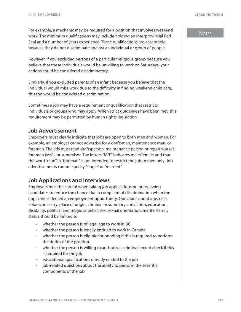
HEAVY MECHANICAL TRADES— FOUNDATION / LEVEL 1 321
NOTES
A-17 EMPLOYMENT LEARNING TASK 6
For example, a mechanic may be required for a position that involves weekend work. The minimum quali�cations may include holding an Interprovincial Red Seal and a number of years experience. These quali�cations are acceptable because they do not discriminate against an individual or group of people.
However, if you excluded persons of a particular religious group because you believe that these individuals would be unwilling to work on Saturdays, your actions could be considered discriminatory.
Similarly, if you excluded parents of an infant because you believe that the individual would miss work due to the di�culty in �nding weekend child care, this too would be considered discrimination.
Sometimes a job may have a requirement or quali�cation that restricts individuals or groups who may apply. When strict guidelines have been met, this requirement may be permitted by human rights legislation.
Job AdvertisementEmployers must clearly indicate that jobs are open to both men and women. For example, an employer cannot advertise for a draftsman, maintenance man, or foreman. The ads must read draftsperson, maintenance person or repair worker, foreman (M/F), or supervisor. The letters “M/F” indicates male/female and that the word “man” in “foreman” is not intended to restrict the job to men only. Job advertisements cannot specify “single” or “married.”
Job Applications and InterviewsEmployers must be careful when taking job applications or interviewing candidates to reduce the chance that a complaint of discrimination when the applicant is denied an employment opportunity. Questions about age, race, colour, ancestry, place of origin, criminal or summary conviction, education, disability, political and religious belief, sex, sexual orientation, marital/family status should be limited to:
• whether the person is of legal age to work in BC• whether the person is legally entitled to work in Canada• whether the person is eligible for bonding if this is required to perform
the duties of the position• whether the person is willing to authorize a criminal record check if this
is required for the job• educational quali�cations directly related to the job• job-related questions about the ability to perform the essential
components of the job
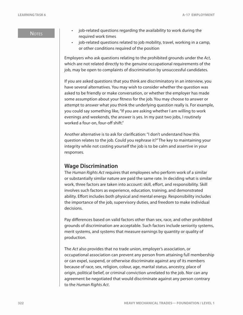
NOTES
322 HEAVY MECHANICAL TRADES— FOUNDATION / LEVEL 1
LEARNING TASK 6 A-17 EMPLOYMENT
• job-related questions regarding the availability to work during the required work times
• job-related questions related to job mobility, travel, working in a camp, or other conditions required of the position
Employers who ask questions relating to the prohibited grounds under the Act, which are not related directly to the genuine occupational requirements of the job, may be open to complaints of discrimination by unsuccessful candidates.
If you are asked questions that you think are discriminatory in an interview, you have several alternatives. You may wish to consider whether the question was asked to be friendly or make conversation, or whether the employer has made some assumption about your �tness for the job. You may choose to answer or attempt to answer what you think the underlying question really is. For example, you could say something like, “If you are asking whether I am willing to work evenings and weekends, the answer is yes. In my past two jobs, I routinely worked a four-on, four-o� shift.”
Another alternative is to ask for clari�cation: “I don’t understand how this question relates to the job. Could you rephrase it?” The key to maintaining your integrity while not costing yourself the job is to be calm and assertive in your responses.
Wage DiscriminationThe Human Rights Act requires that employees who perform work of a similar or substantially similar nature are paid the same rate. In deciding what is similar work, three factors are taken into account: skill, e�ort, and responsibility. Skill involves such factors as experience, education, training, and demonstrated ability. E�ort includes both physical and mental energy. Responsibility includes the importance of the job, supervisory duties, and freedom to make individual decisions.
Pay di�erences based on valid factors other than sex, race, and other prohibited grounds of discrimination are acceptable. Such factors include seniority systems, merit systems, and systems that measure earnings by quantity or quality of production.
The Act also provides that no trade union, employer’s association, or occupational association can prevent any person from attaining full membership or can expel, suspend, or otherwise discriminate against any of its members because of race, sex, religion, colour, age, marital status, ancestry, place of origin, political belief, or criminal conviction unrelated to the job. Nor can any agreement be negotiated that would discriminate against any person contrary to the Human Rights Act.

HEAVY MECHANICAL TRADES— FOUNDATION / LEVEL 1 323
NOTES
A-17 EMPLOYMENT LEARNING TASK 6
Everyone has the right to work in an environment which is free of discrimination and which is conducive to job performance. Workplaces in which workers are subjected to harassment are unhappy places resulting in individuals not performing to the best of their abilities. Harassment creates a “poisoned” atmosphere that does not contribute to cooperation and productivity. The people targeted for harassment may become ill and over-stressed. They may leave the department or workplace in order to escape the harassment. Co-workers may have reduced morale as a result of the lack of respect for others they witness. Ultimately, the e�ects of a less productive and cooperative workplace are felt by the customers of the establishment.
HarassmentHarassment is any physical or verbal conduct by a co-worker, supervisor, or customer that is discriminatory in nature and that o�ends or humiliates you. Although people often think only of sexual harassment, harassment includes any di�erential treatment of people on the basis of their gender, race, ethnic background, class, religion, sexual orientation, age, or disability. Harassment is a type of discrimination. It can take many forms, including:
• threats, intimidation, or verbal abuse• unwelcome remarks or jokes about subjects such as your race, religion,
disability, or age• displaying sexist, racist, or other o�ensive pictures and posters• disparaging names or comments• badgering and constant teasing• o�ensive remarks• unwanted touching• making someone the constant target of practical jokes• sexually suggestive remarks or gestures• stereotyping on the basis of the group to which a person belongs• unfair sharing of responsibilities• physical assault, including sexual assault
Harassment can consist of a single incident or several incidents over a period of time. It is considered to have taken place if a reasonable person ought to have known that the behaviour was unwelcome.
Racist and sexist jokes are sometimes perceived as just having fun. However, even if the person about whom you are joking laughs, it does not mean that he or she enjoys the experience. Jokes of this type can be intimidating and make people ill at ease. They may make people less willing to talk to you because they expect that you will turn their communication with you into more intimidating jokes. Racist and sexist jokes exclude people from your group. They show a lack of respect. They are also harassment. Constant use of racist or sexist expressions
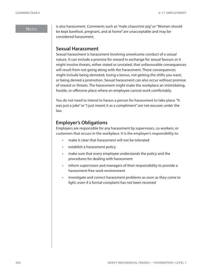
NOTES
324 HEAVY MECHANICAL TRADES— FOUNDATION / LEVEL 1
LEARNING TASK 6 A-17 EMPLOYMENT
is also harassment. Comments such as “male chauvinist pig” or “Women should be kept barefoot, pregnant, and at home” are unacceptable and may be considered harassment.
Sexual HarassmentSexual harassment is harassment involving unwelcome conduct of a sexual nature. It can include a promise for reward in exchange for sexual favours or it might involve threats, either stated or unstated, that unfavourable consequences will result from not going along with the harassment. These consequences might include being demoted, losing a bonus, not getting the shifts you want, or being denied a promotion. Sexual harassment can also occur without promise of reward or threats. The harassment might make the workplace an intimidating, hostile, or o�ensive place where an employee cannot work comfortably.
You do not need to intend to harass a person for harassment to take place. “It was just a joke” or “I just meant it as a compliment” are not excuses under the law.
Employer’s ObligationsEmployers are responsible for any harassment by supervisors, co-workers, or customers that occurs in the workplace. It is the employer’s responsibility to:
• make it clear that harassment will not be tolerated
• establish a harassment policy
• make sure that every employee understands the policy and the procedures for dealing with harassment
• inform supervisors and managers of their responsibility to provide a harassment-free work environment
• investigate and correct harassment problems as soon as they come to light, even if a formal complaint has not been received
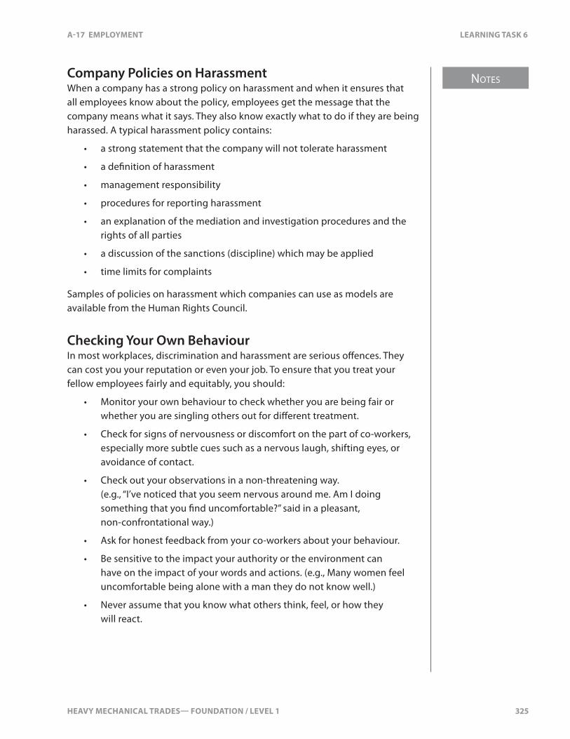
HEAVY MECHANICAL TRADES— FOUNDATION / LEVEL 1 325
NOTES
A-17 EMPLOYMENT LEARNING TASK 6
Company Policies on HarassmentWhen a company has a strong policy on harassment and when it ensures that all employees know about the policy, employees get the message that the company means what it says. They also know exactly what to do if they are being harassed. A typical harassment policy contains:
• a strong statement that the company will not tolerate harassment
• a de�nition of harassment
• management responsibility
• procedures for reporting harassment
• an explanation of the mediation and investigation procedures and the rights of all parties
• a discussion of the sanctions (discipline) which may be applied
• time limits for complaints
Samples of policies on harassment which companies can use as models are available from the Human Rights Council.
Checking Your Own BehaviourIn most workplaces, discrimination and harassment are serious o�ences. They can cost you your reputation or even your job. To ensure that you treat your fellow employees fairly and equitably, you should:
• Monitor your own behaviour to check whether you are being fair or whether you are singling others out for di�erent treatment.
• Check for signs of nervousness or discomfort on the part of co-workers, especially more subtle cues such as a nervous laugh, shifting eyes, or avoidance of contact.
• Check out your observations in a non-threatening way. (e.g., “I’ve noticed that you seem nervous around me. Am I doing something that you �nd uncomfortable?” said in a pleasant, non-confrontational way.)
• Ask for honest feedback from your co-workers about your behaviour.
• Be sensitive to the impact your authority or the environment can have on the impact of your words and actions. (e.g., Many women feel uncomfortable being alone with a man they do not know well.)
• Never assume that you know what others think, feel, or how they will react.

NOTES
326 HEAVY MECHANICAL TRADES— FOUNDATION / LEVEL 1
LEARNING TASK 6 A-17 EMPLOYMENT
Physical or Mental DisabilityPeople with physical or mental disabilities are protected under the Human Rights Act. This protection covers those individuals whose prospects of getting a job and advancing in that job are reduced or a�ected because of a disability. During the hiring process, all applicants should be evaluated on the basis of their ability to carry out the essential components of the job. The employer should:
• concentrate on the person’s capabilities, not disabilities• assess persons as individuals, not as members of a group• avoid making generalizations about disabilities• consider reasonable modi�cations which permit people with disabilities
to perform essential job tasks
Job AccommodationsModi�cations to the job or facility to employ persons with disabilities are called job accommodations. For example, people who are hearing impaired may require a simple light system to alert them to new orders. Often, the person with a disability can tell you exactly what job accommodations are needed. Some government funding may be available for more extensive accommodations.
If an employee is already employed when he or she becomes temporarily or permanently disabled, the employer cannot �re, lay o�, or demote the person because of the disability, unless the individual can no longer perform the essential components of the job. The employer is required to reasonably accommodate the disability. This responsibility is sometimes called the duty to accommodate. Accommodations may include:
• reassigning non-essential work duties• �exible work schedules• physical alteration of facilities• training• technical aids
The BC Human Rights Council would look at such factors as how much the accommodation will cost, the size of the work force, the impact of a collective agreement, and safety considerations.
HEAVY MECHANICAL TRADES— FOUNDATION / LEVEL 1 327
NOTES
A-17 EMPLOYMENT LEARNING TASK 6
Gas Safety BranchThe Safety Standards Act states the regulations in regards to everyone who installs, alters, maintains, or operates gas technologies. If you are working with any gas technology (such as natural gas, propane gas, or liquid natural gas), you must comply with the following regulations:
• Safety Standards Act• Safety Standards General Regulation• Gas Safety Regulation
Before you are able to work on any gas system, you must �rst receive training and obtain a certi�cate of quali�cation.
Motor Vehicle ActThe Motor Vehicle Act states all the rules, regulations, and laws that govern the operation of all motor vehicles on the roads in BC. It de�nes rules of the road, o�ences, and infractions. As a mechanic who inspects and repairs vehicles, you should be familiar with this Act.
ICBCThe Insurance Corporation of British Columbia is delegated under the Motor Vehicle Act to provide direct services to people who operate vehicles in BC. Some of their services include:
• vehicle registration and licensing• driver training, testing, and licensing• administrative processes• maintaining driving records and applying penalty points• receiving payments and applications for reviews of certain sanctions• commercial vehicle safety enforcement (CVSE)

328 HEAVY MECHANICAL TRADES— FOUNDATION / LEVEL 1
SELF TEST 6 A-17 EMPLOYMENT
SELF TEST 6
1. What Act sets the minimum legal standard that all employers must satisfy?
a. BC Unemployment Standards Act
b. BC Employment Standards Act
c. Federal Employee Act
d. BC Fare Standards Act
2. Unless there is a variance, what is the normal hours worked in a week before you may receive overtime pay?
a. 20 hours
b. 40 hours
c. 60 hours
d. 80 hours
3. What code guaranties that every employee is free to be a member of a trade union and to participate in its lawful activities?
a. BC Labour Relations Code
b. BC Code of Conduct
c. BC Union Rights Code
d. BC Federation Code
4. What does Workplace Hazardous Materials Information System (WHMIS) provide information about?
a. colour of material
b. labelling
c. size of Contaminates
d. storage
5. What Act requires that employees who perform work of a similar or substantially similar in nature are paid the same rate?
a. Fair Wage Act
b. Equal Rights Act
c. Human Rights Act
d. Equality Act

HEAVY MECHANICAL TRADES— FOUNDATION / LEVEL 1 329
A-17 EMPLOYMENT SELF TEST 6
6. What Act states all the rules, regulations and laws that govern the operation of all motor vehicles on the roads in BC?
a. Motor Vehicle Act
b. Rules of the Road Act
c. ICBC Act
d. Vehicles and Road Act
7. Who is delegated to provide vehicles registration services, driver testing and CVSE?
a. Motor Vehicle Centres
b. Insurance Corporation of BC
c. Co-ops of BC
d. Motor Vehicle Insurance Centres

330 HEAVY MECHANICAL TRADES— FOUNDATION / LEVEL 1

HEAVY MECHANICAL TRADES— FOUNDATION / LEVEL 1 331
NOTES
A-17 EMPLOYMENT LEARNING TASK 7
LEARNING TASK 7
Describe Positive Employee Attributes
Mechanical skills are only part of what employers seek in an employee. For most employers, commitment, enthusiasm, dependability, honesty, the willingness to learn, and the ability to accept criticism are at the top of their list of expectations. Employers want people who can communicate e�ectively with other co-workers, work as a team, and respect others in the workplace. As a mechanic, you need to have the ability to solve problems and look into the causes instead of just the repair. With the constant changes in the Heavy Mechanical Trades, you must be open to learning new concepts and technologies. When working on equipment, you must maintain a high level of quality and professionalism. How you present yourself to employers, co-workers, and customers (both visually and verbally) a�ects your career as a mechanic.
CommunicationMaintaining good communication is important for any company. Any breakdown in communication can have far-reaching e�ects on your ability to do your job and on the company’s ability to reach its objectives. If directions are not fully or clearly given, you may not understand the exact procedures that must be followed or may not be aware of the speci�c materials that should be used. In order for work to be done correctly, you need to seek clari�cation if you have not understood or are unsure about certain procedures or methods.
In small businesses where the owner-manager runs all aspects of the business, communication is usually informal and mainly by word of mouth. The employees are given their assignments by the owner and report back when the work is done. As companies get bigger and develop separate departments or divisions, much more information is conveyed in writing. Written communication enables employees to re-read complex information and to deal with it at their own convenience. It makes it possible for copies to be distributed to a variety of interested parties, serves as evidence of instructions given, and provides a written record for later veri�cation.
For e�ciency, companies also develop procedures and policies to clarify how the information is passed. This process is called establishing channels of communication. For example, a purchase order you �ll out may have to be signed by your supervisor for authorization before it can be handled by the purchasing o�ce.
NOTES
332 HEAVY MECHANICAL TRADES— FOUNDATION / LEVEL 1
LEARNING TASK 7 A-17 EMPLOYMENT
For a company to work e�ectively, information must �ow in all directions. It must �ow from management to the worker, between co-workers, and from the workers back to management. As an employee, you have a right to expect clear directions from your supervisor on work assignments and accurate information on company policies and procedures that a�ect you. It is your responsibility to report on work progress and to make suggestions to your supervisor.
Skill in communication is of great value in any organization and is vital in getting along with others. Knowing how to say what you want tactfully yet forcefully and asking questions in a positive way are the basis of good communication skills.
E�ective communication is honest and direct and should state your needs and wants in a clear and objective manner. Negative or accusatory statements set you up for potential con�icts and other forms of uncooperative behaviour on the part of your co-workers. This can impair your ability to do your job well.
At times, you must deal directly with customers—it may be necessary to help them understand the problems encountered and provide alternatives. This type of communication is necessary to ensure that the customer knows that you’re performing only work that is requested and required.
You must write clear and complete reports on work being performed. These reports may be used by a service manager to explain to the customer what repairs have been completed. Unclear reports can create misunderstandings that cause the customer to lose faith in the company. The success of a company relies a great deal on customer’s goodwill and word-of-mouth recommendations. The customer’s feelings and perceptions must always be taken into account.
ThinkingThe Heavy Mechanical Trades involve much problem solving. Any mechanic can replace a part with a new one, but a quality mechanic will be able to diagnose a problem and determine what needs to be repaired or replaced. They will also be able to �nd the cause of the failure and recommend procedures to prevent the failure from happening again. Many systems are computer controlled, which involve following diagnostic procedures and performing reprogramming of computers. You must be able to learn new technologies and adapt to various operating systems. If you can do this, you will be very successful.
HEAVY MECHANICAL TRADES— FOUNDATION / LEVEL 1 333
NOTES
A-17 EMPLOYMENT LEARNING TASK 7
Desire to Continue LearningModern equipment and vehicles have come a long way in the last 100 years. In the last 20 years, computer control systems have evolved and are now in nearly every type of equipment or vehicle. As a mechanic in this trade, you have to keep up with changes. You have to seek out new technology and stay current. Upgrading your skills makes you more valuable to your employer.
Positive AttitudeOne of the most important qualities for getting along with co-workers is a positive attitude. Having a good attitude involves several things: a willingness to work diligently, pursuing de�nite goals, being pleasant to the public, and being courteous, respectful, and helpful to your co-workers. By maintaining a good attitude, you’re telling people that you care.
Honesty and integrity are important qualities in the workplace. Employers are always looking for someone they can trust and depend upon. Employers also look for people with initiative and a drive to advance their careers. The right attitude can help you move into a supervisory or management position.
ResponsibilityYou are responsible for the decisions you make in your life. As a mechanic, you’ll make many decisions every day—some simple, others complicated. A simple decision is the one to show up on time and begin your work right away. More complex decisions involve deciding what parts need repairing or replacement. You’re responsible for managing your time, working e�ectively, and completing jobs on schedule.
AdaptabilityOne constant in the Heavy Mechanical Trades is change. Changes can be daily, such as the type of equipment you work on or the type of repair. Changes can be more gradual, such as technology, types of equipment, working conditions, or your job status. The ability to adapt to change is another attribute employers want to see in their employees.
NOTES
334 HEAVY MECHANICAL TRADES— FOUNDATION / LEVEL 1
LEARNING TASK 7 A-17 EMPLOYMENT
Team SkillsEvery employer is looking for a team player. A team player is person who can work with others to get a job done, or share new ideas or concepts with co-workers. Team players listen to others and respect their opinion. At times, you may be a team leader whereas other times, you’ll be a follower. In both situations, it’s important that you work with the team towards your objective.
Care for QualityAs a mechanic in the Heavy Mechanical Trades, the quality of your work must be one of your highest priorities. The vehicles and equipment you will work on can cost in the hundreds of thousands, or even millions, of dollars. If you do a poor job, it can be costly to your company to correct the mistakes, it can cost the equipment owner lost revenue, it may even cost someone their life. Make sure that whatever job you do, no matter how small or large, it’s done to the best of your ability.
Personal CareAppearance can a�ect your acceptance in any organization. Remember that you have only one chance to make a �rst impression. Give thought to your clothes and grooming before starting a new job. After you’re hired, remember that you’re representing not only yourself, but the company you work for. What you wear and how you handle yourself can a�ect how you’re perceived by others. Wearing clean coveralls, safety attire, and keeping clean are good habits to have. Make sure that you’re prepared to work your full shift, even when that’s a 12-hour day. Being well-rested and leaving any “baggage” at home makes sure your head is clear and focused on the job at hand.
Drug or alcohol abuse cannot be tolerated on the job site—any substance abuse can result in serious personal or equipment damage. Many large work sites have random testing to ensure everyone is “clean.” If drugs or alcohol are found in your system, you are usually �red on the spot and escorted o� the property.

HEAVY MECHANICAL TRADES— FOUNDATION / LEVEL 1 335
NOTES
A-17 EMPLOYMENT LEARNING TASK 7
Following Safety RegulationsFollowing workplace safety regulations is your responsibility. You do not want to be responsible for an injury to yourself or a co-worker. After being hired, you’ll undergo safety training. Your employer will explain the safety regulations you must follow. Safety is everyone’s responsibility so if you see something unsafe, you must correct the situation. WorkSafeBC has province-wide safety standards and your employer may have their own additional procedures.
The following chart clari�es some attributes:
Acceptable Attributes Unacceptable Attributes
Workers who are committed:
• try to make the company look good
• work hard for the organization
• do their best
• dress appropriately
Workers who lack commitment:
• criticize their organization to outsiders
• are mostly concerned about what the organization can do for them
Workers who are enthusiastic:
• are interested in their work
• share their ideas
• are cheerful
• give others help
Workers who are unenthusiastic:
• do only enough to get by
• do not care about the quality of the work
• may be uncooperative
• are complainers
Workers who are dependable:
• arrive at work on time
• �nish assigned work on schedule
• call when they miss work due to illness
• ful�ll commitments
• use sick days only for legitimate illness or injury
Workers who are not dependable:
• arrive at work late
• do not �nish assigned work
• miss work without notifying employer
• are often absent from work
• make excuses to not follow through on commitments
Workers who are honest:
• admit their mistakes
• express their opinions
Workers who are dishonest:
• take tools or materials for their own use
• try to get away with as much as they can
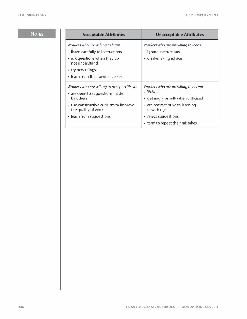
NOTES
336 HEAVY MECHANICAL TRADES— FOUNDATION / LEVEL 1
LEARNING TASK 7 A-17 EMPLOYMENT
Acceptable Attributes Unacceptable Attributes
Workers who are willing to learn:
• listen carefully to instructions
• ask questions when they do not understand
• try new things
• learn from their own mistakes
Workers who are unwilling to learn:
• ignore instructions
• dislike taking advice
Workers who are willing to accept criticism:
• are open to suggestions made by others
• use constructive criticism to improve the quality of work
• learn from suggestions
Workers who are unwilling to accept criticism:
• get angry or sulk when criticized
• are not receptive to learning new things
• reject suggestions
• tend to repeat their mistakes

HEAVY MECHANICAL TRADES— FOUNDATION / LEVEL 1 337
A-17 EMPLOYMENT SELF TEST 7
SELF TEST 7
1. What are some key attributes a mechanic must have to be successful in this trade?
a. steady hands, nerves of steel, and a strong back
b. likes to get dirty, small in stature, and a high tolerance to pain
c. dependability, willingness to learn, and good communication skills
d. loud talker, �exible, and willingness to do whatever it takes to complete the job
2. Who sets the province wide safety standards?
a. BC Working Safely
b. ICBC
c. Safety BC
d. WorkSafeBC

338 HEAVY MECHANICAL TRADES— FOUNDATION / LEVEL 1
HEAVY MECHANICAL TRADES— FOUNDATION / LEVEL 1 339
NOTES
A-17 EMPLOYMENT LEARNING TASK 8
LEARNING TASK 8
Describe Employer Responsibility
Your employer has certain responsibilities when it comes to dealing with employees. They must treat their employees with respect, and trust they’re going to perform their duties as instructed. The employer is responsible for maintaining a healthy and safe work environment. Some of the responsibilities are:
• establish and maintain a joint health and safety committee, or instruct workers to select at least one health and safety representative
• take every reasonable precaution to ensure the workplace is safe
• train employees about potential hazards; how to safely use, handle, store, and dispose of hazardous substances; and how to handle emergencies
• supply personal protective equipment and ensure workers know how to use it safely and correctly
• immediately report all critical injuries to the government department responsible for Occupational Health & Safety
• appoint a competent supervisor who sets the standards for performance, and who ensures safe working conditions
The employer is responsible for payment of wages and bene�ts to the employee. The employer has to keep track of all the hours an employee works and pay any overtime. The employer is also responsible for deducting income tax, Canada Pension Plan, Employment Insurance, and union or professional dues. They also pay for uniforms (coveralls), cleaning, and maintenance. The employer has to follow the applicable legislation concerning workplace issues. They may have to follow the BC Labour Relations Code or The Employment Standards Act depending on whether it is a union or non-union company.
There is no Self Test for this learning task.

340 HEAVY MECHANICAL TRADES— FOUNDATION / LEVEL 1
HEAVY MECHANICAL TRADES— FOUNDATION / LEVEL 1 341
NOTES
A-17 EMPLOYMENT LEARNING TASK 9
LEARNING TASK 9
Prepare a Resume
An e�ective resume is critical to acquiring a job. There are di�erent types of resumes depending on your work history and the type of job for which you’re applying. The resume you create for your �rst job will be di�erent than the resume you create when looking for a change of jobs. However, in both cases, you’re trying to highlight your skills and abilities to the prospective employer. You’re also demonstrating your potential to become the employee the employer is looking for. Generally, a resume should be about two pages long, highlighting your skills, experience, and education.
Gathering InformationBefore writing a resume, you must �rst consider all the types of information you’ll need to include:
• personal information• education• skills• work experience• references
Personal InformationInclude personal information such as your full name, permanent address, and telephone number (home and cell). You want to make it easy for the employer to contact you in case of further questions or a job o�er.
EducationYour resume should provide details of your education including certi�cates such as foundation training or Red Seals. List any diplomas or degrees you have achieved. If you’ve attended more than one training provider, list them starting with the most recent. Include the training provider’s address, the dates you attended, and the certi�cate, diploma, or degree you received. Note any certi�cates from specialized training such as forklift, WHMIS, air endorsement, or original equipment manufacturer’s training.
NOTES
342 HEAVY MECHANICAL TRADES— FOUNDATION / LEVEL 1
LEARNING TASK 9 A-17 EMPLOYMENT
SkillsList any relevant skills or abilities you’ve developed over the years. See below for a list of skills that may be added to your resume.
Technical or Specialized:• critical thinking• evaluate situations• solve math problems• interpret results of diagnosis• computer skills• quick learner• committed to lifelong learning
Communication:• speak and write the language of the industry• listen to learn• listen to understand• understand schematics and diagrams• contribute to the team• work with a team• respect the opinion of others• be a leader
Personal Management Skills:• positive attitude• self-con�dence• accept responsibility• learn from others• set goals and priorities• self-motivated• suggest new ideas
It’s best if you can demonstrate your particular skills with an example, e.g., rather than stating “I can work with a team,” describe how “I worked with a volunteer organization to build a race car.”
Work ExperienceYour resume should list your work history. Your list may be short if you’re just starting out, or it could be quite long if you’ve changed jobs often. Start with your most recent employer. Include the company name, address, your title, and your starting and ending dates. You may want to list any accomplishments made or work performed while at that company.
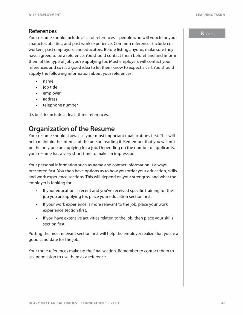
HEAVY MECHANICAL TRADES— FOUNDATION / LEVEL 1 343
NOTES
A-17 EMPLOYMENT LEARNING TASK 9
ReferencesYour resume should include a list of references—people who will vouch for your character, abilities, and past work experience. Common references include co-workers, past employers, and educators. Before listing anyone, make sure they have agreed to be a reference. You should contact them beforehand and inform them of the type of job you’re applying for. Most employers will contact your references and so it’s a good idea to let them know to expect a call. You should supply the following information about your references:
• name• job title• employer• address• telephone number
It’s best to include at least three references.
Organization of the ResumeYour resume should showcase your most important quali�cations �rst. This will help maintain the interest of the person reading it. Remember that you will not be the only person applying for a job. Depending on the number of applicants, your resume has a very short time to make an impression.
Your personal information such as name and contact information is always presented �rst. You then have options as to how you order your education, skills, and work experience sections. This will depend on your strengths, and what the employer is looking for.
• If your education is recent and you’ve received speci�c training for the job you are applying for, place your education section �rst.
• If your work experience is more relevant to the job, place your work experience section �rst.
• If you have extensive activities related to the job, then place your skills section �rst.
Putting the most relevant section �rst will help the employer realize that you’re a good candidate for the job.
Your three references make up the �nal section. Remember to contact them to ask permission to use them as a reference.
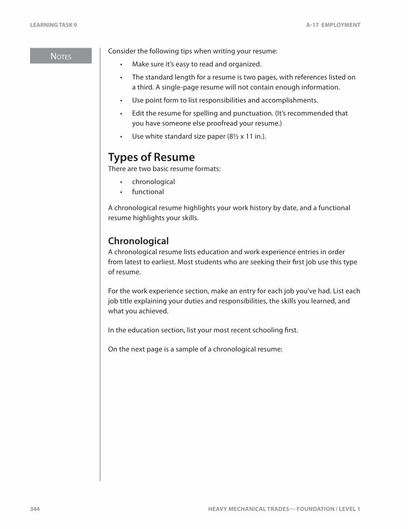
NOTES
344 HEAVY MECHANICAL TRADES— FOUNDATION / LEVEL 1
LEARNING TASK 9 A-17 EMPLOYMENT
Consider the following tips when writing your resume:
• Make sure it’s easy to read and organized.
• The standard length for a resume is two pages, with references listed on a third. A single-page resume will not contain enough information.
• Use point form to list responsibilities and accomplishments.
• Edit the resume for spelling and punctuation. (It’s recommended that you have someone else proofread your resume.)
• Use white standard size paper (8½ x 11 in.).
Types of ResumeThere are two basic resume formats:
• chronological• functional
A chronological resume highlights your work history by date, and a functional resume highlights your skills.
ChronologicalA chronological resume lists education and work experience entries in order from latest to earliest. Most students who are seeking their �rst job use this type of resume.
For the work experience section, make an entry for each job you’ve had. List each job title explaining your duties and responsibilities, the skills you learned, and what you achieved.
In the education section, list your most recent schooling �rst.
On the next page is a sample of a chronological resume:

HEAVY MECHANICAL TRADES— FOUNDATION / LEVEL 1 345
NOTES
A-17 EMPLOYMENT LEARNING TASK 9
John Smith 1234 Main St.
(604) 555-‐1234 (home) (604) 555-‐9989 (cell)
Education 2011 – present BC Training Institute Vancouver BC Intermediate Metal-‐working
2009 – 2011 Cameron College Kamloops BC Introductory Mechanical Training
2006 – 2009 Kitsilano High School Majored in Mechanics Graduated with honors
Work Experience 2010 – present A1 Garage 459 Elm St., Vancouver BC Junior Mechanic
2008 – 2010 Family Food Mart 890 Johnson Ave, Kamloops BC Stockboy, cashier
Awards and Recognition • Top mechanic student bursary $500
• Top vocational trades student 2009
Interests and Activities • Riding quads
• Hiking
• Camping
• Rebuilding old cars
References Mr. Fred Jones A1 Garage (604) 555-‐6282
Mr. Gerry Smith Kitsilano High School (604) 555-‐7452
Ms. Janet Gilmour Family Food Mart [email protected]
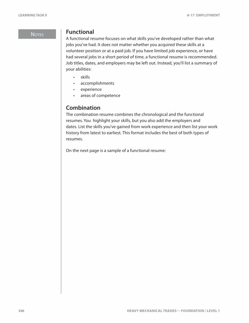
NOTES
346 HEAVY MECHANICAL TRADES— FOUNDATION / LEVEL 1
LEARNING TASK 9 A-17 EMPLOYMENT
FunctionalA functional resume focuses on what skills you’ve developed rather than what jobs you’ve had. It does not matter whether you acquired these skills at a volunteer position or at a paid job. If you have limited job experience, or have had several jobs in a short period of time, a functional resume is recommended. Job titles, dates, and employers may be left out. Instead, you’ll list a summary of your abilities:
• skills• accomplishments• experience• areas of competence
CombinationThe combination resume combines the chronological and the functional resumes. You highlight your skills, but you also add the employers and dates. List the skills you’ve gained from work experience and then list your work history from latest to earliest. This format includes the best of both types of resumes.
On the next page is a sample of a functional resume:
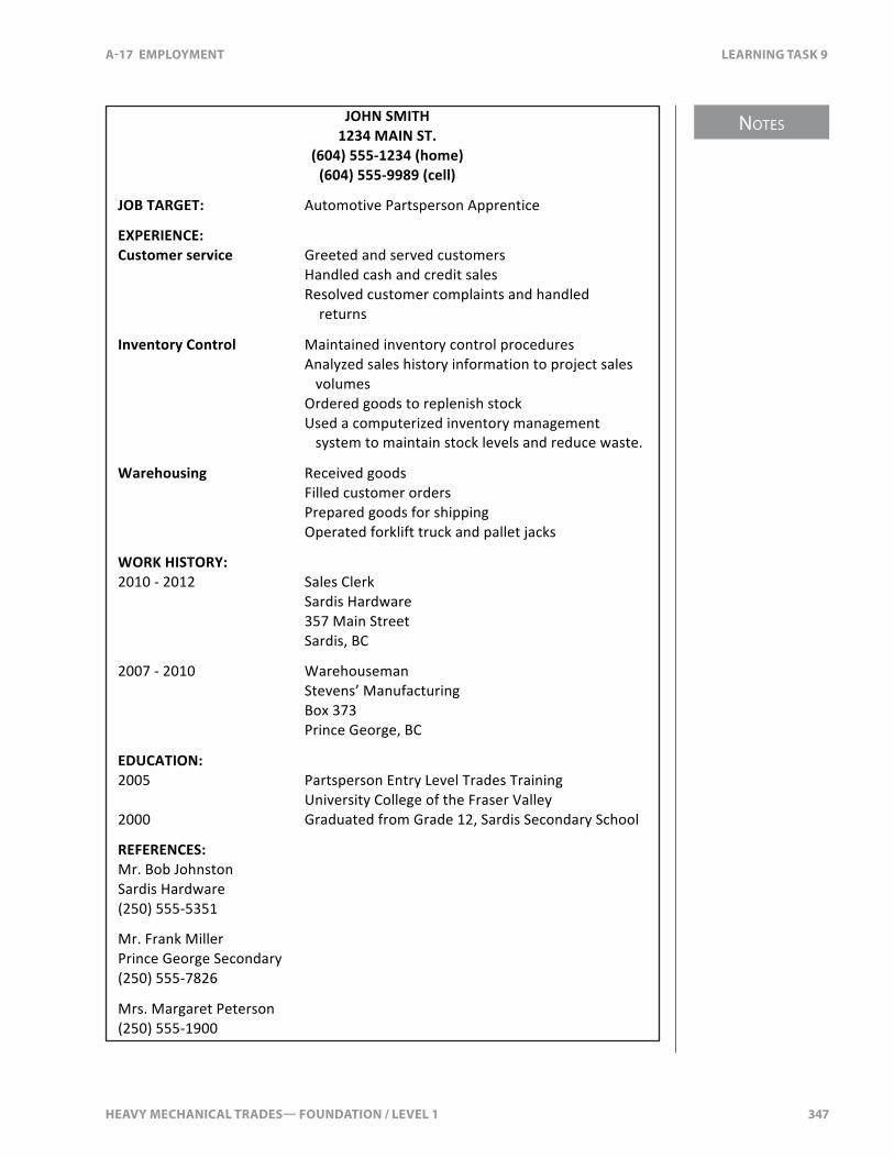
HEAVY MECHANICAL TRADES— FOUNDATION / LEVEL 1 347
NOTES
A-17 EMPLOYMENT LEARNING TASK 9
JOHN SMITH 1234 MAIN ST.
(604) 555-‐1234 (home) (604) 555-‐9989 (cell)
JOB TARGET: Automotive Partsperson Apprentice
EXPERIENCE: Customer service Greeted and served customers
Handled cash and credit sales Resolved customer complaints and handled returns
Inventory Control Maintained inventory control procedures Analyzed sales history information to project sales volumes Ordered goods to replenish stock Used a computerized inventory management system to maintain stock levels and reduce waste.
Warehousing Received goods Filled customer orders
Prepared goods for shipping Operated forklift truck and pallet jacks
WORK HISTORY: 2010 -‐ 2012 Sales Clerk
Sardis Hardware 357 Main Street Sardis, BC
2007 -‐ 2010 Warehouseman Stevens’ Manufacturing Box 373 Prince George, BC
EDUCATION: 2005 Partsperson Entry Level Trades Training University College of the Fraser Valley 2000 Graduated from Grade 12, Sardis Secondary School
REFERENCES: Mr. Bob Johnston Sardis Hardware (250) 555-‐5351
Mr. Frank Miller Prince George Secondary (250) 555-‐7826
Mrs. Margaret Peterson (250) 555-‐1900

348 HEAVY MECHANICAL TRADES— FOUNDATION / LEVEL 1
SELF TEST 9 A-17 EMPLOYMENT
SELF TEST 9
1. What should be in your resume?
a. education, skills, and experience
b. age, sexual orientation, and education
c. height, weight, and religion
d. references, medical history, and wage required
2. How many references should be included in your resume?
a. 1
b. 3
c. 5
d. 7
3. What are the two main types of resumes?
a. paradigm and logical
b. anthology and prodigy
c. chronological and functional
d. reasonable and extreme

HEAVY MECHANICAL TRADES— FOUNDATION / LEVEL 1 349
NOTES
A-17 EMPLOYMENT LEARNING TASK 10
LEARNING TASK 10
Prepare a Cover Letter
The purpose of a cover letter is to introduce yourself and your resume to a potential employer. It’s intended to show that you have the skills and abilities necessary for the job. It also demonstrates your ability to communicate e�ectively. The cover letter gives you an opportunity to sell yourself and encourage the prospective employer to invite you for an interview.
A solicited letter is in response to an advertisement for a job posting. You should focus on the skills listed in the advertisement.
An unsolicited letter is given to a company even though they may not be looking to hire at that time. It may be given to a company you want to work for in the future. An unsolicited cover letter should tell the company what you can do for them and why you’re quali�ed to work for them.
CompositionComposition is a key to a successful cover letter. The letter should be no more than one page. The �rst paragraph will be an opening introduction. The middle paragraphs should cover your knowledge of the company, your training, and your work experience. Finally, you have a closing paragraph.
Opening ParagraphThe opening paragraph should concern the advertisement you’re responding to, or the job you’re seeking. You should brie�y describe your quali�cations for the job. If you’re writing a solicited letter, you should mention the competition number in this paragraph, or where you saw the advertisement. If you’re writing an unsolicited letter, you should mention how you became aware of the company, and why you want to work there.
Middle ParagraphsThe middle paragraphs show you’re interested in their company and to give them a reason to invite you for an interview. You need to demonstrate that you have skills and abilities that would be a bene�t to them. Brie�y list your relevant training, education, and experience. These paragraphs should answer the two questions a prospective employer will be thinking:
• Why do you wish to work for us?• Why should I hire you?
NOTES
350 HEAVY MECHANICAL TRADES— FOUNDATION / LEVEL 1
LEARNING TASK 10 A-17 EMPLOYMENT
To answer these questions, you need to do some homework on the company. You also need to highlight your skills and training relevant to the job. Although a lot of the information is the same, you do not want to include everything on your resume in a cover letter. Rather, you want your cover letter to be an invitation for the employer to read your resume.
Closing ParagraphThe closing paragraph is your opportunity to request an interview and leave contact information. You want to be clear you’re hoping for an interview. You may suggest a follow-up phone call or visit to the company. Finally, mention that you’re including your resume.
Tips for writing an e�ective cover letter:
• address the letter to an individual, position, or department• use a word processor, unless the employer has asked for a
hand-written letter• use positive statements about your education and experience• avoid using the word “I” too often—instead mix in “my”• tailor each cover letter to the company and job you are applying for

HEAVY MECHANICAL TRADES— FOUNDATION / LEVEL 1 351
A-17 EMPLOYMENT SELF TEST 10
SELF TEST 10
1. What is a solicited cover letter?
a. the employer has requested the letter
b. response to an advertisement for a job posting
c. requesting a job position
d. requesting a job interview

352 HEAVY MECHANICAL TRADES— FOUNDATION / LEVEL 1

HEAVY MECHANICAL TRADES— FOUNDATION / LEVEL 1 353
NOTES
A-17 EMPLOYMENT LEARNING TASK 11
LEARNING TASK 11
Identify Job Search Sources
There are many sources you can use to �nd a job:
• newspapers• internet• networking• industry publications• job fairs• direct approach• head hunters
NewspapersAt one time, newspaper classi�ed ads were the main source of job leads. However, as internet use has increased, the importance of want ads has declined. Want ads can still be helpful for some types of job-seekers, particularly those seeking entry-level positions. It’s worth noting that career experts do not place great value on want ads since these positions are often �lled by the time the ads are published. You can check your local newspaper or newspapers from larger cities.
InternetRecent trends in job-hunting have been to use the Internet to search for openings and post resumes. There are hundreds of thousands of jobs listed on thousands of job websites. Search for either a particular job description, or for the company for which you want to work. A bene�t of these sites is that many also include company pro�les and other important information you can use to gain an understanding of each employer. Many job-seekers have received interviews from these postings.
Tips for online job-searching:
• On the search line, enter combinations of words to re�ne your search. Try “employment advertisements,” “job listings,” “careers,” “Canada,” “British Columbia.” Use di�erent combinations of the words and di�erent search engines. Bookmark pages that you �nd useful.
• Once you have found a useful site, check out any links.
• Check how frequently the website is updated. Websites that are updated daily or weekly will be more useful than ones that are updated less frequently.
NOTES
354 HEAVY MECHANICAL TRADES— FOUNDATION / LEVEL 1
LEARNING TASK 11 A-17 EMPLOYMENT
• Check to see whether the companies, organizations, or institutions charge fees for the services they list on their websites. For example, there may be a cost to post your resume. Read the terms of use thoroughly before using a service the website provides. Websites maintained by educational institutions and government ministries or departments do not charge for their services.
• The Internet is used by millions of people each day. Be extremely careful about providing any personal information such as your name, address, or telephone number over the Internet.
NetworkingNetworking provides the vast majority of job leads. The phrase “it’s not what you know, it’s who you know” still rings true. More job leads are found through networking than any other method. Networking involves using the people you know: your family, friends, neighbours, colleagues, customers, vendors, and associates. The more people in your network, the greater number of job prospects you have. Even when you’re not currently searching for a job, you should be working on growing and strengthening your network.
Industry PublicationsEvery �eld has at least one professional organization that publishes magazines. Truck and heavy duty machinery magazines are two types of publications where employers may post their advertisements. There may be postings in magazines that sell machines, trucks, and trailers. Many of these magazines are distributed across Canada.
Job FairsIndustries also participate in job fairs. Companies attend these fairs to meet and recruit top prospects. Your goal is to prepare beforehand and identify the key employers in attendance and then develop a strategy for breaking through the clutter of other job-seekers. Even if the employer is not in the market for someone with your mix of skills and experience, you can still get your foot in the door through this method.
HEAVY MECHANICAL TRADES— FOUNDATION / LEVEL 1 355
NOTES
A-17 EMPLOYMENT LEARNING TASK 11
Direct ApproachThe direct approach has become something of a lost art, but one that can uncover a “hidden job market.” This method involves compiling a list of potential employers. This list can come from numerous sources, including business and trade periodicals, company directories, even the phone book. Once you’ve prepared a speci�c cover letter and resume, you’ll go to each company and talk with the manager or owner. You may not always get the opportunity to talk directly to them, but always leave your resume and then follow up a few days later. Persistence pays o�, and if you’re visiting their company regularly, they will become familiar with you. If, at a later date, they’re looking for someone, they may contact you before using other methods to �nd an employee. If the company is out of town, mail your cover letter and resume to them.
Head HuntersHead hunters are intermediaries who are paid to get job-seekers and employers in contact with each other. Sometimes, companies will hire a head hunter to �nd suitable applicants for a job opening. You’ll �nd head hunters using many of the same methods you use to �nd a job.
To be successful in your job-search, you need to develop as many job leads as possible, and to follow-up each one. Once you submit your cover letter and resume, be sure to follow-up a short time later to con�rm that your material was received. Be professional in your follow-up. You may want to consider developing a “follow-up log.” This will help you keep track of each job lead, the date you followed-up, and the name of the person you spoke with.

356 HEAVY MECHANICAL TRADES— FOUNDATION / LEVEL 1
SELF TEST 11 A-17 EMPLOYMENT
SELF TEST 11
1. What is networking referring to when �nding a new job?
a. using the internet
b. using the television
c. using people you know
d. using the newspaper

HEAVY MECHANICAL TRADES— FOUNDATION / LEVEL 1 357
NOTES
A-17 EMPLOYMENT LEARNING TASK 12
LEARNING TASK 12
Prepare for an Interview
Most employers compile a short-list of candidates from the applications they receive, and then interview these people. You have to be prepared for an interview. It’s critical that you present yourself in a professional manner.
Research the OrganizationPreparing for an interview begins with �nding out as much as possible about the company. Find out as much as you can about the position, the employer, and its needs. What do they sell? Who are their clients? Are they a �eet? What type of equipment do they use? Knowing these facts will help you demonstrate how your background meets their needs. Research the company on the Internet and at your local library. Employers are as interested in your questions as they are in your answers. It’s an advantage if you ask intelligent questions about the position, the company, and the industry.
Review of Job Quali�cationsYou must be familiar with the job quali�cations. The employer will be referring to the job posting and the type of skills or certi�cates required for the job. You’ll have to explain your quali�cations and how they compare to the company’s requirements. It might seem simple, but if you stumble at the basics, you’ll never get to the more complicated questions. You may be asked about your work experiences and skills acquired. Don’t be afraid to admit mistakes, but turn it into a positive by explaining what you did to overcome that situation.
Prepare for Broad Personal QuestionsEmployers use interviews to gauge whether you have the qualities to perform the job well. They’re looking for ability and aptitude, a willingness to work, a desire to achieve goals, maturity, and compatibility. Employers will also watch to see how you react when di�cult questions are asked. You may be asked how you handled a particular situation in the past. (This is a good indicator to the employer as to how you will handle yourself in the future.) When answering questions, look the prospective employer in the eye. Show enthusiasm as this can enhance your chances of success. You want appear con�dent with yourself and your background.
NOTES
358 HEAVY MECHANICAL TRADES— FOUNDATION / LEVEL 1
LEARNING TASK 12 A-17 EMPLOYMENT
Interviews use a question and answer format. You should be prepared to answer questions such as:
• Can you tell me something about yourself?
• What are your future plans?
• Why do you want to work here?
• Can you work under pressure and deadlines?
• Why did you leave your last employer? or Why do you want to leave your present employer?
• What are your strengths?
• What are your weaknesses or limitations?
• Why should I hire you?
They may even ask questions speci�c to the Heavy Mechanical Trades.
Review of ResumeYou should bring a copy of your cover letter and resume to the interview even though they will have your original. The interviewer may ask speci�c questions about your resume and it’s important that you answer without needing to read it. If there are gaps in your work experience, you must be able to explain those.
Interview PracticeIt may seem strange to practice for an interview, but you need to give the best impression you can. Have a friend interview you and practice answering questions you think you’ll be asked. Practice your posture, explanations, and body language. Make the situation similar to what would happen in an actual interview. Place a table and chairs in a room just as it would be in an interview. Prepare questions that you’d like to ask the interviewer. If possible, video-tape your practice interview so you can see how you look and act during the process. The more prepared you are, the better your chance of success.

HEAVY MECHANICAL TRADES— FOUNDATION / LEVEL 1 359
NOTES
A-17 EMPLOYMENT LEARNING TASK 12
Personal AppearanceIn an ideal world, you’ll be hired based solely on your skills and abilities. However, it’s human nature to judge based on appearance and so �rst impressions are critical to your success. Most employers form a �rst impression within the �rst seven seconds of meeting. Since very little is said during these seven seconds, early judgment is often based strictly on appearance. Studies reveal that employers consistently ask the question, “Does the individual look right for the job?” Your personal appearance may not get you a job, but it can de�nitely cost you a job. A positive impression at the start usually makes the rest of the interview con�rm that impression. Starting with a negative �rst impression makes the rest of the interview that much more di�cult.
Although there are no absolute rules regarding dress, you should wear clothes appropriate to the position for which you’re applying. Your selection will vary based on your occupation, location, and preference. Inappropriate wear includes a business suit when applying for a construction job, or wearing overalls when applying for an o�ce job. The goal is to look the part, and your appearance should be consistent with your occupation. Neat, clean work clothes are appropriate for assembly, production, or warehouse positions. Sales and o�ce positions require business clothes. A conservative suit is the recommended style for professional and managerial positions. Common sense and good taste are the best guides in selecting clothing for an interview. Avoid faddish styles and loud colours.
Jewelry should be conservative and kept to a minimum. Clothing should �t comfortably. You want the employer to focus on your skills, not your clothes.
Some basic guidelines to follow:
• be clean and neat, including your �ngernails, teeth, hair, and face
• have empty pockets—no bulges or rattling coins/keys, etc.
• do not chew gum, eat candy, or smoke cigarettes
• carry a light briefcase or portfolio case
• remove visible body piercings (nose, eyebrow, tongue, etc.)
• wear minimal jewelry and cologne
NOTES
360 HEAVY MECHANICAL TRADES— FOUNDATION / LEVEL 1
LEARNING TASK 12 A-17 EMPLOYMENT
Arriving Ahead of TimeBeing punctual is critical during an interview. If you’re late for an interview, the employer will suspect that you’ll be late for work as well. Prior to the interview, check its location and determine how long it will take you to get there. On the day of the interview, allow extra time in case of tra�c problems—arriving early is much better than arriving late.
Applicants can be rejected for many reasons:
• poor personal appearance and hygiene
• an overbearing, conceited attitude
• poor communication skills
• lack of clear career goals
• lack of interest, commitment, and enthusiasm for the job
• lack of con�dence and poise
• overemphasis on what the employer o�ers them (salary, bene�ts, vacation)
• lack of tact, maturity, and courtesy
• poor attitude about the job, previous employers, or school
• failure to look interviewer in the eye
• a limp handshake
• inability to relate skills and experience to the job
• lack of knowledge about the company
• obvious personal problems
• lack of tolerance, strong prejudices, and narrow interests
There is no Self Test for this learning task.

HEAVY MECHANICAL TRADES— FOUNDATION / LEVEL 1 361
NOTES
A-17 EMPLOYMENT LEARNING TASK 13
LEARNING TASK 13
Follow up on an Interview
Before the end of the interview, you should request a follow-up phone call or email. Ask the interviewer for a business card so you have contact information. That evening, send the person a thank you email. You should also send a letter in the mail thanking them for the interview and pointing out that you’re very interested. If you haven’t heard from the interviewer after four or �ve days, make a follow-up phone call. State that you’re still interested in working for their company and ask if they have any further questions. If you get a voice mail, leave a message. After these initial steps, call or email once a week until they tell you that you’re hired or that the position is �lled. Although some people may feel that you’re hounding them, other employers wait to see who contacts them to determine who really wants to work for them.
On the next page is a sample of a follow-up letter.

NOTES
362 HEAVY MECHANICAL TRADES— FOUNDATION / LEVEL 1
LEARNING TASK 13 A-17 EMPLOYMENT
John Smith 1234 Main St. Vancouver, BC V5Y 1V4 (604) 555-‐7625 [email protected]
2012/06/25 Harold Jones Shop Foreman ABC Construction Ltd. 480 Commercial Dr. Vancouver, BC V7T 1G8 Dear Mr. Jones,
Thank you for taking the time out of your busy schedule to talk with me about the mechanical position with ABC Construction Ltd. I appreciate your time and consideration in interviewing me for this position.
After speaking with you and the group, I believe that I would be a perfect candidate for this job, offering the quick learning and adaptability that is needed for an entry level position.
In addition to my enthusiasm for performing well, I would bring the technical and analytical skills necessary to get the job done.
I am very interested in working for you and look forward to hearing from you once the final decisions are made regarding this position. Please feel free to contact me at any time if further information is needed. My cell phone number is (604) 555-‐7625.
Thank you again for your time and consideration.
Sincerely,
John Smith

HEAVY MECHANICAL TRADES— FOUNDATION / LEVEL 1 363
A-17 EMPLOYMENT SELF TEST 13
SELF TEST 13
1. What should be done after your job interview with a prospective employer?
a. buy co�ee and doughnuts
b. email or call back
c. send �owers
d. wait for a reply

364 HEAVY MECHANICAL TRADES— FOUNDATION / LEVEL 1
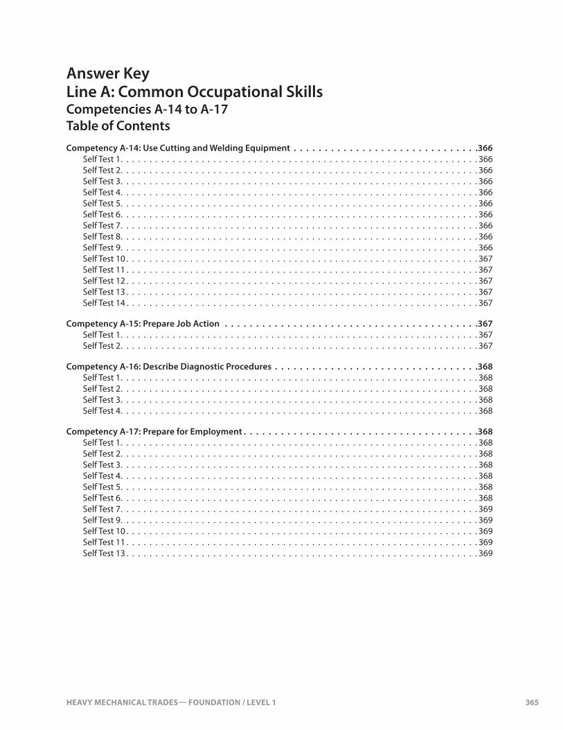
HEAVY MECHANICAL TRADES— FOUNDATION / LEVEL 1 365
Answer Key Line A: Common Occupational SkillsCompetencies A-14 to A-17Table of ContentsCompetency A-14: Use Cutting and Welding Equipment . . . . . . . . . . . . . . . . . . . . . . . . . . . . . .366
Self Test 1. . . . . . . . . . . . . . . . . . . . . . . . . . . . . . . . . . . . . . . . . . . . . . . . . . . . . . . . . . . . . . 366Self Test 2. . . . . . . . . . . . . . . . . . . . . . . . . . . . . . . . . . . . . . . . . . . . . . . . . . . . . . . . . . . . . . 366Self Test 3. . . . . . . . . . . . . . . . . . . . . . . . . . . . . . . . . . . . . . . . . . . . . . . . . . . . . . . . . . . . . . 366Self Test 4. . . . . . . . . . . . . . . . . . . . . . . . . . . . . . . . . . . . . . . . . . . . . . . . . . . . . . . . . . . . . . 366Self Test 5. . . . . . . . . . . . . . . . . . . . . . . . . . . . . . . . . . . . . . . . . . . . . . . . . . . . . . . . . . . . . . 366Self Test 6. . . . . . . . . . . . . . . . . . . . . . . . . . . . . . . . . . . . . . . . . . . . . . . . . . . . . . . . . . . . . . 366Self Test 7. . . . . . . . . . . . . . . . . . . . . . . . . . . . . . . . . . . . . . . . . . . . . . . . . . . . . . . . . . . . . . 366Self Test 8. . . . . . . . . . . . . . . . . . . . . . . . . . . . . . . . . . . . . . . . . . . . . . . . . . . . . . . . . . . . . . 366Self Test 9. . . . . . . . . . . . . . . . . . . . . . . . . . . . . . . . . . . . . . . . . . . . . . . . . . . . . . . . . . . . . . 366Self Test 10 . . . . . . . . . . . . . . . . . . . . . . . . . . . . . . . . . . . . . . . . . . . . . . . . . . . . . . . . . . . . . 367Self Test 11 . . . . . . . . . . . . . . . . . . . . . . . . . . . . . . . . . . . . . . . . . . . . . . . . . . . . . . . . . . . . . 367Self Test 12 . . . . . . . . . . . . . . . . . . . . . . . . . . . . . . . . . . . . . . . . . . . . . . . . . . . . . . . . . . . . . 367Self Test 13 . . . . . . . . . . . . . . . . . . . . . . . . . . . . . . . . . . . . . . . . . . . . . . . . . . . . . . . . . . . . . 367Self Test 14 . . . . . . . . . . . . . . . . . . . . . . . . . . . . . . . . . . . . . . . . . . . . . . . . . . . . . . . . . . . . . 367
Competency A-15: Prepare Job Action . . . . . . . . . . . . . . . . . . . . . . . . . . . . . . . . . . . . . . . . .367Self Test 1. . . . . . . . . . . . . . . . . . . . . . . . . . . . . . . . . . . . . . . . . . . . . . . . . . . . . . . . . . . . . . 367Self Test 2. . . . . . . . . . . . . . . . . . . . . . . . . . . . . . . . . . . . . . . . . . . . . . . . . . . . . . . . . . . . . . 367
Competency A-16: Describe Diagnostic Procedures . . . . . . . . . . . . . . . . . . . . . . . . . . . . . . . . .368Self Test 1. . . . . . . . . . . . . . . . . . . . . . . . . . . . . . . . . . . . . . . . . . . . . . . . . . . . . . . . . . . . . . 368Self Test 2. . . . . . . . . . . . . . . . . . . . . . . . . . . . . . . . . . . . . . . . . . . . . . . . . . . . . . . . . . . . . . 368Self Test 3. . . . . . . . . . . . . . . . . . . . . . . . . . . . . . . . . . . . . . . . . . . . . . . . . . . . . . . . . . . . . . 368Self Test 4. . . . . . . . . . . . . . . . . . . . . . . . . . . . . . . . . . . . . . . . . . . . . . . . . . . . . . . . . . . . . . 368
Competency A-17: Prepare for Employment . . . . . . . . . . . . . . . . . . . . . . . . . . . . . . . . . . . . . .368Self Test 1. . . . . . . . . . . . . . . . . . . . . . . . . . . . . . . . . . . . . . . . . . . . . . . . . . . . . . . . . . . . . . 368Self Test 2. . . . . . . . . . . . . . . . . . . . . . . . . . . . . . . . . . . . . . . . . . . . . . . . . . . . . . . . . . . . . . 368Self Test 3. . . . . . . . . . . . . . . . . . . . . . . . . . . . . . . . . . . . . . . . . . . . . . . . . . . . . . . . . . . . . . 368Self Test 4. . . . . . . . . . . . . . . . . . . . . . . . . . . . . . . . . . . . . . . . . . . . . . . . . . . . . . . . . . . . . . 368Self Test 5. . . . . . . . . . . . . . . . . . . . . . . . . . . . . . . . . . . . . . . . . . . . . . . . . . . . . . . . . . . . . . 368Self Test 6. . . . . . . . . . . . . . . . . . . . . . . . . . . . . . . . . . . . . . . . . . . . . . . . . . . . . . . . . . . . . . 368Self Test 7. . . . . . . . . . . . . . . . . . . . . . . . . . . . . . . . . . . . . . . . . . . . . . . . . . . . . . . . . . . . . . 369Self Test 9. . . . . . . . . . . . . . . . . . . . . . . . . . . . . . . . . . . . . . . . . . . . . . . . . . . . . . . . . . . . . . 369Self Test 10 . . . . . . . . . . . . . . . . . . . . . . . . . . . . . . . . . . . . . . . . . . . . . . . . . . . . . . . . . . . . . 369Self Test 11 . . . . . . . . . . . . . . . . . . . . . . . . . . . . . . . . . . . . . . . . . . . . . . . . . . . . . . . . . . . . . 369Self Test 13 . . . . . . . . . . . . . . . . . . . . . . . . . . . . . . . . . . . . . . . . . . . . . . . . . . . . . . . . . . . . . 369
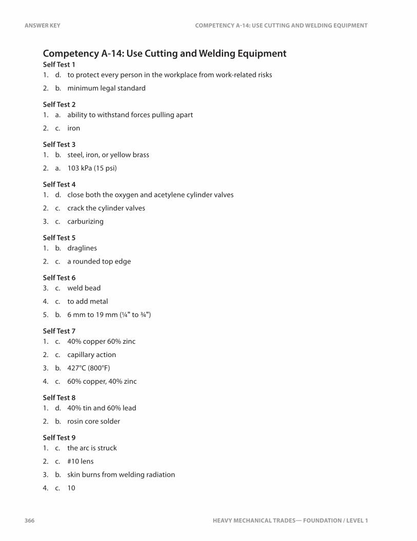
366 HEAVY MECHANICAL TRADES— FOUNDATION / LEVEL 1
ANSWER KEY COMPETENCY A-14: USE CUTTING AND WELDING EQUIPMENT
Competency A-14: Use Cutting and Welding EquipmentSelf Test 11. d. to protect every person in the workplace from work-related risks
2. b. minimum legal standard
Self Test 21. a. ability to withstand forces pulling apart
2. c. iron
Self Test 31. b. steel, iron, or yellow brass
2. a. 103 kPa (15 psi)
Self Test 41. d. close both the oxygen and acetylene cylinder valves
2. c. crack the cylinder valves
3. c. carburizing
Self Test 51. b. draglines
2. c. a rounded top edge
Self Test 63. c. weld bead
4. c. to add metal
5. b. 6 mm to 19 mm (¼" to ¾")
Self Test 71. c. 40% copper 60% zinc
2. c. capillary action
3. b. 427°C (800°F)
4. c. 60% copper, 40% zinc
Self Test 81. d. 40% tin and 60% lead
2. b. rosin core solder
Self Test 91. c. the arc is struck
2. c. #10 lens
3. b. skin burns from welding radiation
4. c. 10
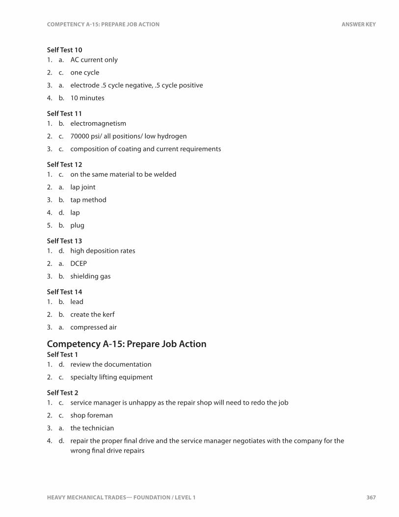
HEAVY MECHANICAL TRADES— FOUNDATION / LEVEL 1 367
COMPETENCY A-15: PREPARE JOB ACTION ANSWER KEY
Self Test 101. a. AC current only
2. c. one cycle
3. a. electrode .5 cycle negative, .5 cycle positive
4. b. 10 minutes
Self Test 111. b. electromagnetism
2. c. 70000 psi/ all positions/ low hydrogen
3. c. composition of coating and current requirements
Self Test 121. c. on the same material to be welded
2. a. lap joint
3. b. tap method
4. d. lap
5. b. plug
Self Test 131. d. high deposition rates
2. a. DCEP
3. b. shielding gas
Self Test 141. b. lead
2. b. create the kerf
3. a. compressed air
Competency A-15: Prepare Job ActionSelf Test 11. d. review the documentation
2. c. specialty lifting equipment
Self Test 21. c. service manager is unhappy as the repair shop will need to redo the job
2. c. shop foreman
3. a. the technician
4. d. repair the proper �nal drive and the service manager negotiates with the company for the wrong �nal drive repairs
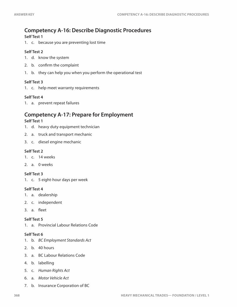
368 HEAVY MECHANICAL TRADES— FOUNDATION / LEVEL 1
ANSWER KEY COMPETENCY A-16: DESCRIBE DIAGNOSTIC PROCEDURES
Competency A-16: Describe Diagnostic ProceduresSelf Test 11. c. because you are preventing lost time
Self Test 21. d. know the system
2. b. con�rm the complaint
1. b. they can help you when you perform the operational test
Self Test 31. c. help meet warranty requirements
Self Test 41. a. prevent repeat failures
Competency A-17: Prepare for EmploymentSelf Test 11. d. heavy duty equipment technician
2. a. truck and transport mechanic
3. c. diesel engine mechanic
Self Test 21. c. 14 weeks
2. a. 0 weeks
Self Test 31. c. 5 eight-hour days per week
Self Test 41. a. dealership
2. c. independent
3. a. �eet
Self Test 51. a. Provincial Labour Relations Code
Self Test 61. b. BC Employment Standards Act
2. b. 40 hours
3. a. BC Labour Relations Code
4. b. labelling
5. c. Human Rights Act
6. a. Motor Vehicle Act
7. b. Insurance Corporation of BC

HEAVY MECHANICAL TRADES— FOUNDATION / LEVEL 1 369
COMPETENCY A-17: PREPARE FOR EMPLOYMENT ANSWER KEY
Self Test 71. c. dependability, willingness to learn, and good communication skills
2. d. WorkSafeBC
Self Test 91. a. education, skills, and experience
2. b. 3
3. c. chronological and functional
Self Test 101. b. response to an advertisement for a job posting
Self Test 111. c. using people you know
Self Test 131. b. email or call back

Heavy Duty Mechanical Lines and CompetenciesLine A Common Occupational Skills Line F Trailer
A-1 Use Safe Work Practices F-1 Service Landing Gear and Trailer AccessoriesA-2 Apply Occupational Health and Safety F-2 Service and Repair Coupling SystemsA-3 Use Environmental Practices F-3 Service, Diagnose, and Repair Trailer Body ComponentsA-4 Use Hand Tools, Power Tools, and Shop Equipment F-4 Service, Diagnose, and Repair Trailer Heating andA-5 Use Fasteners and Fittings Refrigeration SystemsA-6 Lift and Support Loads A-7 Operate Equipment Line G Heating, Ventilation and AirA-8 Use Shop Resources and Record Keeping Practices G-1 Describe Heating and Air Conditioning FundamentalsA-9 Service Winch Wire Rope G-2 Diagnose and Repair Heating andA-10 Identify Lubricants Air Conditioning SystemsA-11 Service Bearings and Seals A-12 Apply Math and Science Line H Engines and Supporting SystemsA-13 Use Electronic Media H-1 Describe Engine FundamentalsA-14 Use Cutting and Welding Equipment H-2 Service Engine Support SystemsA-15 Prepare Job Action H-3 Diagnose and Repair Engine Support SystemsA-16 Describe Diagnostic Procedures H-4 Service Diesel Fuel Supply SystemsA-17 Prepare for Employment H-5 Diagnose and Repair Diesel Supply Systems H-6 Service Gasoline Fuel Systems
Line B Brakes H-7 Describe Alternative Fuel SystemsB-1 Service and Repair Hydraulic Brakes H-8 Diagnose Engines and ComponentsB-2 Service and Repair Hydraulic Power Brakes H-9 Remove and Install Diesel EnginesB-3 Service and Repair Air Brakes H-10 Repair Engines and ComponentsB-4 Diagose and Repair Advanced Brake Systems H-11 Describe Diesel Fuel Injection Fundamentals H-12 Diagnose and Repair Mechanical Fuel
Line C Hydraulics Injection SystemsC-1 Describe Hydraulic Systems H-13 Diagnose and Repair Electronic Diesel Fuel SystemsC-2 Service Hydraulic Components H-14 Diagnose and Repair Diesel Emission SystemsC-3 Diagnose and Repair Advanced Hydraulic Systems H-15 Diagnose and Repair Engine Brakes H-16 Service, Diagnose, and Repair Electronic
Line D Electrical Ignition SystemsD-1 Describe Electricity D-2 Use Electrical Testing Instruments Line I PowertrainD-3 Service and Diagnose Batteries I-1 Describe Power Transfer SystemsD-4 Service Charging Systems I-2 Service ClutchesD-5 Diagnose and Repair Charging Systems I-3 Diagnose and Repair ClutchesD-6 Service Starting Systems I-4 Service Manual TransmissionsD-7 Diagnose and Repair Starting Systems I-5 Diagnose and Repair Manual TransmissionsD-8 Service Electrical and Electronic Circuits I-6 Diagnose and Repair Automated TransmissionsD-9 Diagnose and Repair Electrical Components I-7 Service Torque Converters and Dividers and Systems I-8 Service Powershift and Automatic TransmissionD-10 Diagrnose and Repair Electronic Compoments I-9 Diagnose and Repair Automatic Transmissions and and Systems Torque ConvertersD-11 Diagrnose and Repair Vehicle Management Systems I-10 Diagnose and Repair Powershift TransmissionsD-12 Service, Diagnose, and Repair Hybrid Systems I-11 Service DrivelinesD-13 Service, Diagnose, and Repair Electric Drive Systems I-12 Diagnose and Repair Drivelines I-13 Service Drive Axles
Line E Suspension and Steering I-14 Diagnose and Repair Drive AxlesE-1 Service and Diagnose Tires, Wheels, and Hubs I-15 Service Final DrivesE-2 Service Steering Systems I-16 Diagnose and Repair Final DrivesE-3 Diagnose and Repair Truck Hydraulic Assisted I-17 Diagnose and Repair Driveline Retarders Steering Systems I-18 Diagnose and Repair Winches E-4 Service, Diagnose, and Repair Machine I-19 Diagnose and Repair Power Takeoffs and Suspension Systems Transfer CasesE-5 Remove and Install Undercarriage I-20 Remove and Install TransmissionsE-6 Diagnose and Repair Frames I-21 Remove and Install Driveline and DifferentialsE-7 Align Vehicle I-22 Remove and Install Final DrivesE-8 Diagnose and Repair Wheeled Equipment Steering E-9 Diagnose and Repair Track Machine Steering Line J Structural Components and AccessoriesE-10 Diagnose and Repair Undercarriage J-1 Indentify Protective Structures J-2 Service Cab Structures J-3 Repair Advanced Cab and Body Structures J-4 Diagnose and Repair Working Attachments J-5 Diagnose and Repair Pnuematic System