Limits, Fits and Tolerances - me.iitb.ac.inramesh/courses/ME338/ssp3.pdf · Evaluate limits and...
31
Limits, Fits and Tolerances Prof. S. S. Pande Mechanical Engineering Department Indian Institute of Technology, Bombay 1
Transcript of Limits, Fits and Tolerances - me.iitb.ac.inramesh/courses/ME338/ssp3.pdf · Evaluate limits and...

Limits, Fits and Tolerances
Prof. S. S. Pande
Mechanical Engineering Department
Indian Institute of Technology, Bombay
1
Outline
• Basic Definitions
• ISO system for Tolerance Specification
• Tolerance Design for assembly- Fits
• Design of Limit Gages
• Taylor’s Principle
Permissible variation in the size (dimension) of a component to suit Functional Requirements
What is Tolerance ?
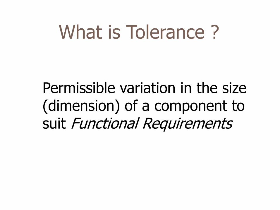
How to choose Tolerance?
• Part Function
• Cost of Production
• Productivity (Time)
• Availability of Manufacturing Resources
Tolerance
Time Cost
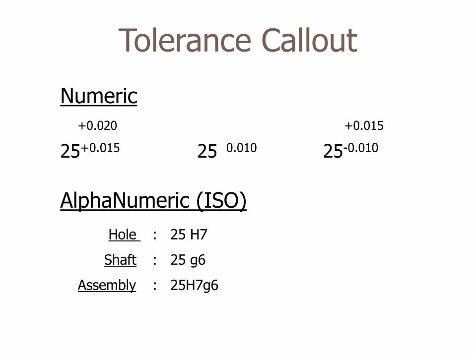
Tolerance Callout
Numeric
+0.020 +0.015
25+0.015 25
0.010 25-0.010
AlphaNumeric (ISO)
Hole : 25 H7
Shaft : 25 g6
Assembly : 25H7g6
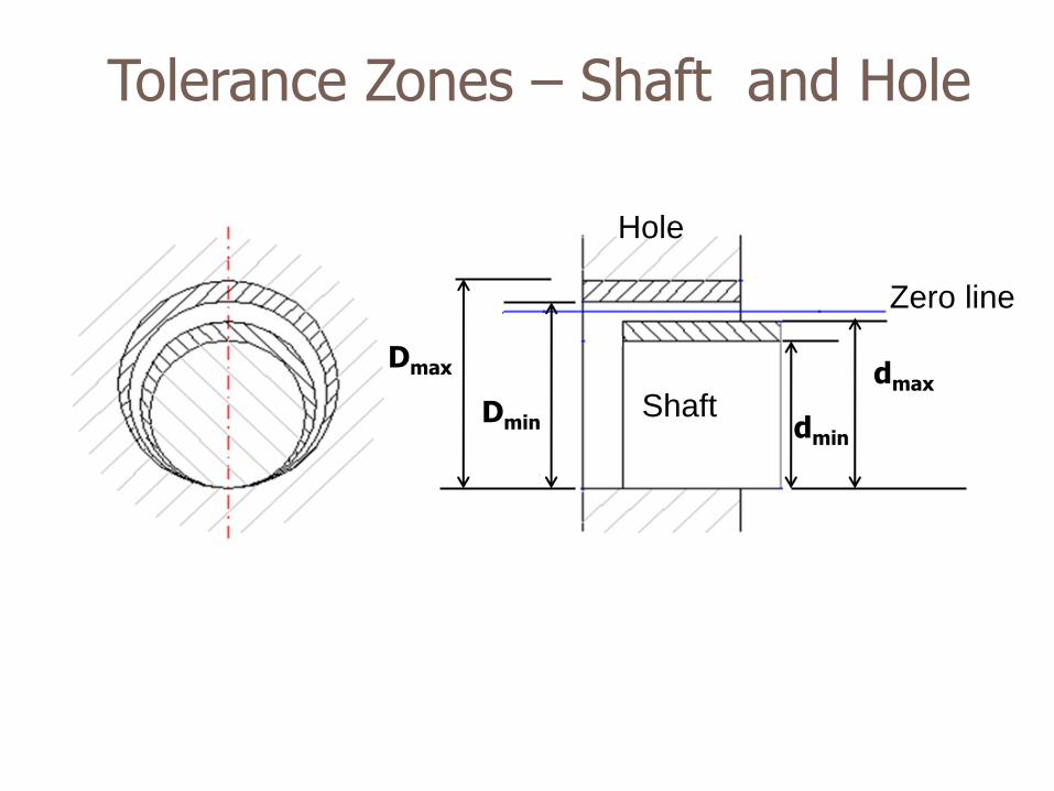
Tolerance Zones – Shaft and Hole
Dmax
Dmin dmin
dmax
Zero line
Shaft
Hole
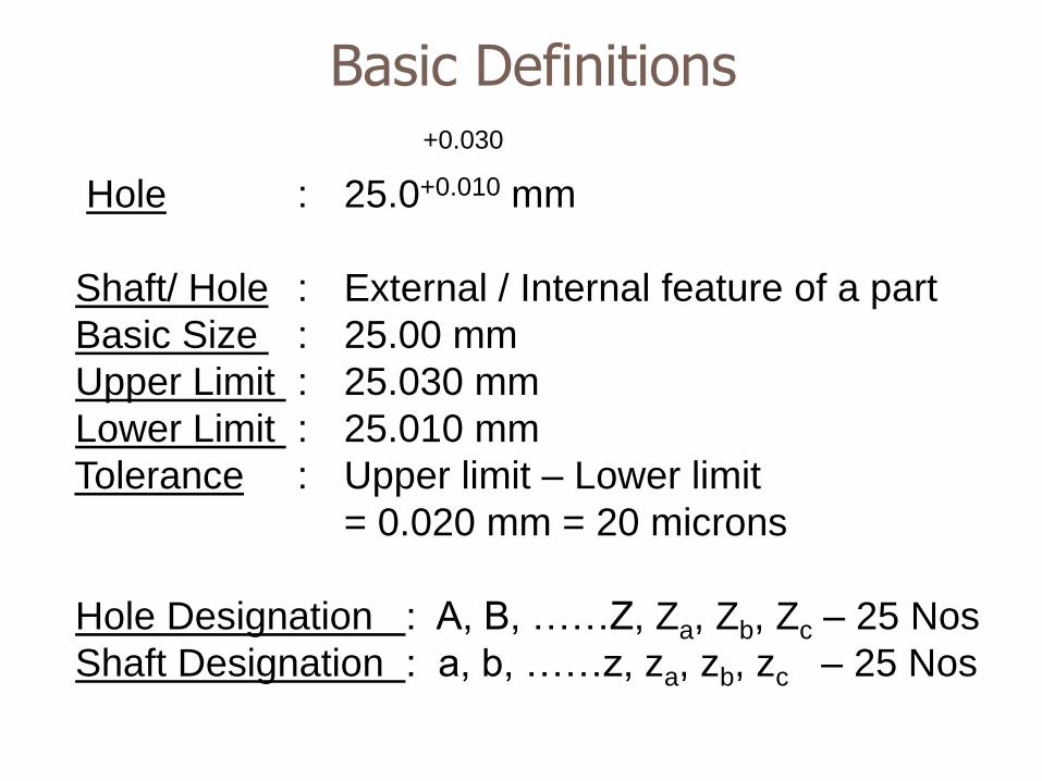
+0.030
Hole : 25.0+0.010 mm
Shaft/ Hole : External / Internal feature of a part
Basic Size : 25.00 mm
Upper Limit : 25.030 mm
Lower Limit : 25.010 mm
Tolerance : Upper limit – Lower limit
= 0.020 mm = 20 microns
Hole Designation : A, B, ……Z, Za, Zb, Zc – 25 Nos
Shaft Designation : a, b, ……z, za, zb, zc – 25 Nos
Basic Definitions
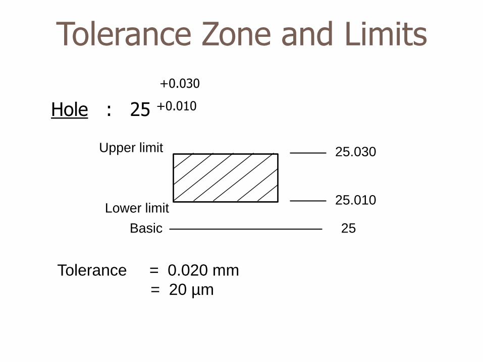
Tolerance Zone and Limits
+0.030 Hole : 25 +0.010
Upper limit
Lower limit
25
25.030
25.010
Basic
Tolerance = 0.020 mm
= 20 µm
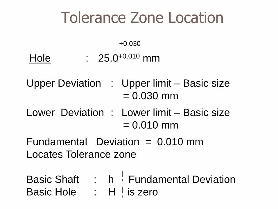
+0.030
Hole : 25.0+0.010 mm
Upper Deviation : Upper limit – Basic size
= 0.030 mm
Lower Deviation : Lower limit – Basic size
= 0.010 mm
Fundamental Deviation = 0.010 mm
Locates Tolerance zone
Basic Shaft : h Fundamental Deviation
Basic Hole : H is zero
Tolerance Zone Location
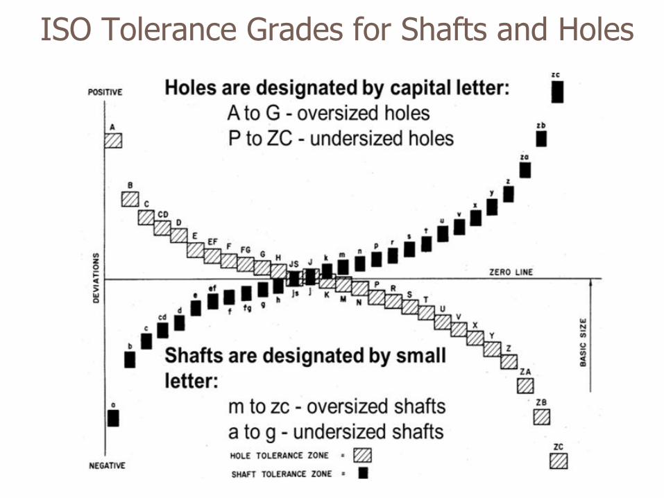
ISO Tolerance Grades for Shafts and Holes
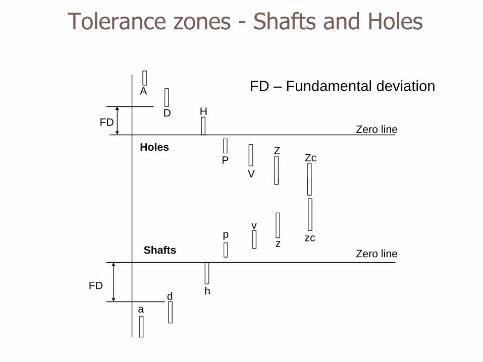
Holes
A
D H
P
V
Z Zc
FD Zero line
Shafts
a
d h
p v
z zc
FD
Zero line
Tolerance zones - Shafts and Holes
FD – Fundamental deviation
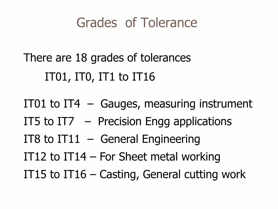
Grades of Tolerance
There are 18 grades of tolerances
IT01, IT0, IT1 to IT16 IT01 to IT4 – Gauges, measuring instrument
IT5 to IT7 – Precision Engg applications
IT8 to IT11 – General Engineering
IT12 to IT14 – For Sheet metal working
IT15 to IT16 – Casting, General cutting work
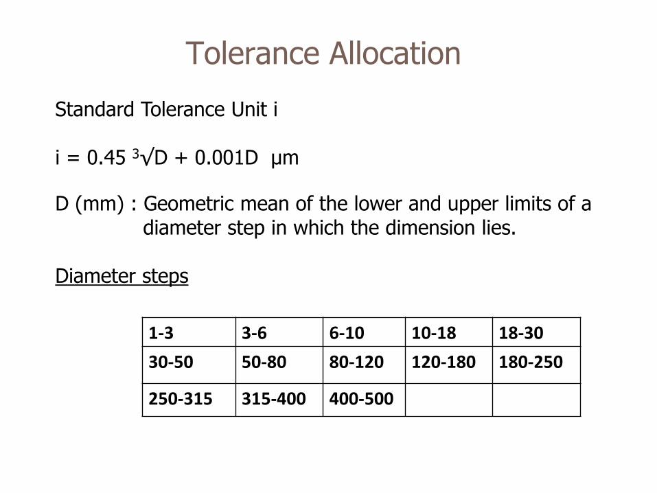
Tolerance Allocation
Standard Tolerance Unit i i = 0.45 3√D + 0.001D μm
D (mm) : Geometric mean of the lower and upper limits of a diameter step in which the dimension lies. Diameter steps
1-3 3-6 6-10 10-18 18-30
30-50 50-80 80-120 120-180 180-250
250-315 315-400 400-500
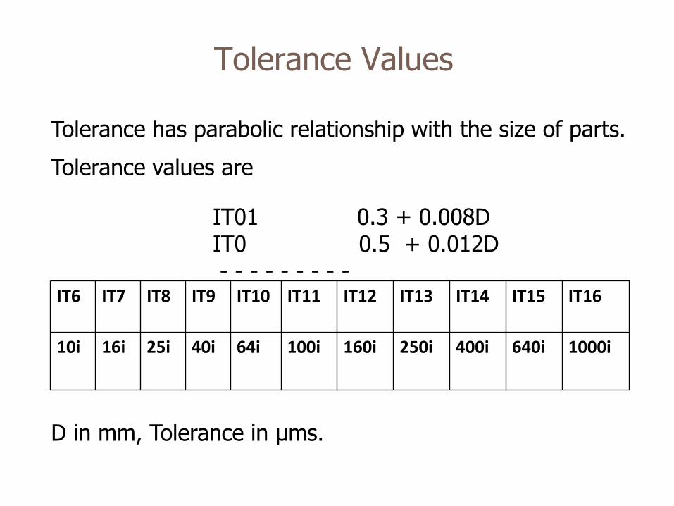
Tolerance Values
Tolerance has parabolic relationship with the size of parts.
Tolerance values are
IT01 0.3 + 0.008D IT0 0.5 + 0.012D - - - - - - - - - D in mm, Tolerance in μms.
IT6 IT7
IT8 IT9 IT10 IT11 IT12 IT13 IT14 IT15 IT16
10i 16i 25i 40i 64i 100i 160i 250i 400i 640i 1000i
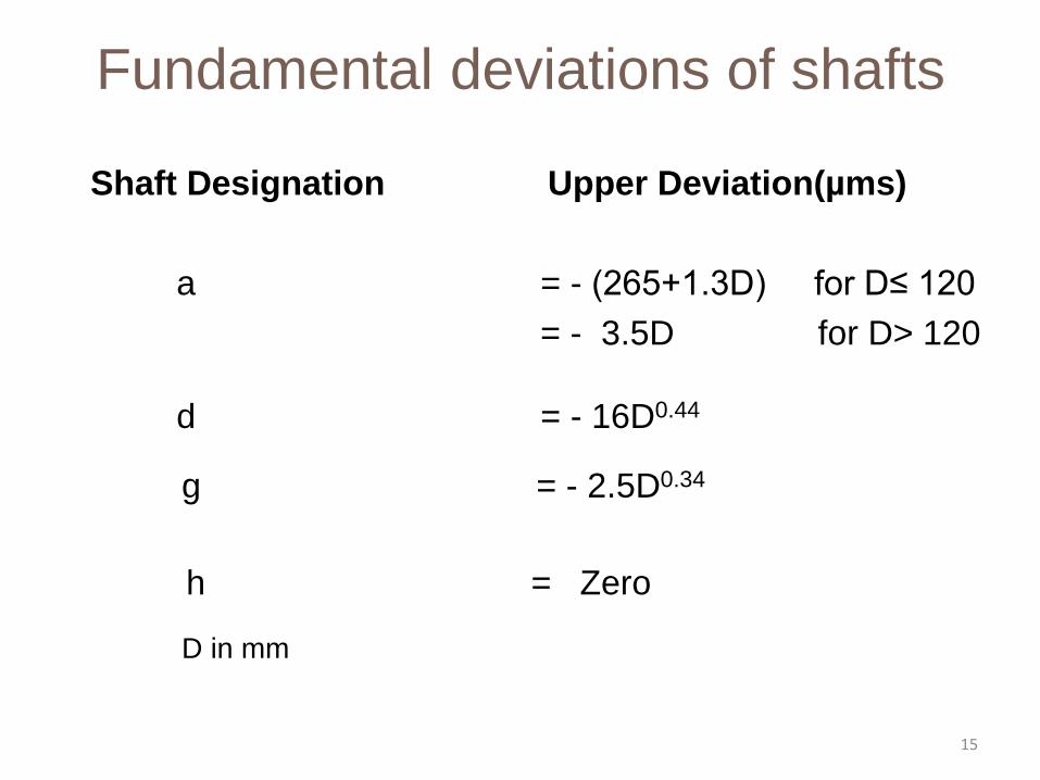
Fundamental deviations of shafts
Shaft Designation Upper Deviation(µms)
a = - (265+1.3D) for D≤ 120
= - 3.5D for D> 120
d = - 16D0.44
g = - 2.5D0.34
h = Zero
D in mm
15
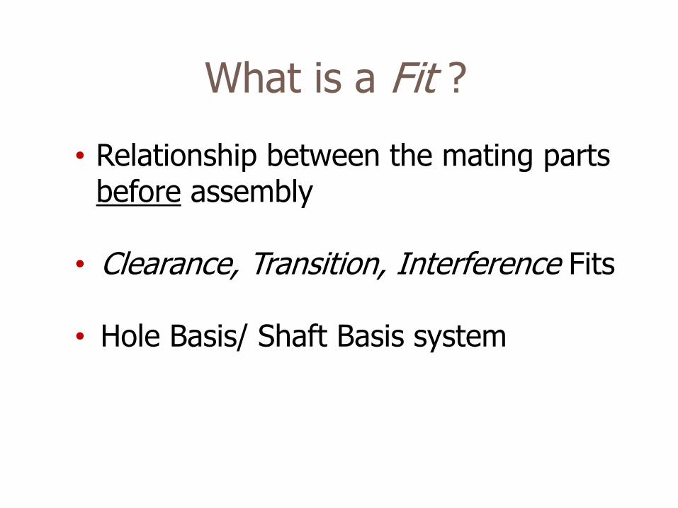
What is a Fit ?
• Relationship between the mating parts before assembly
• Clearance, Transition, Interference Fits • Hole Basis/ Shaft Basis system
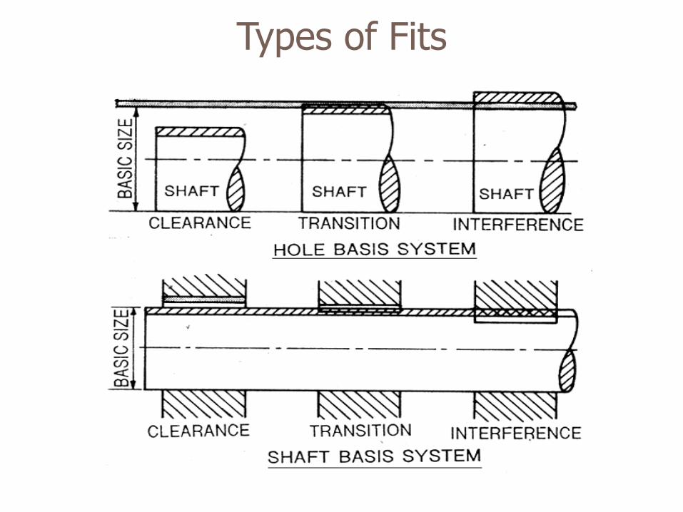
Types of Fits
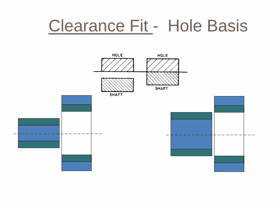
Clearance Fit - Hole Basis

Transition Fit –Hole Basis
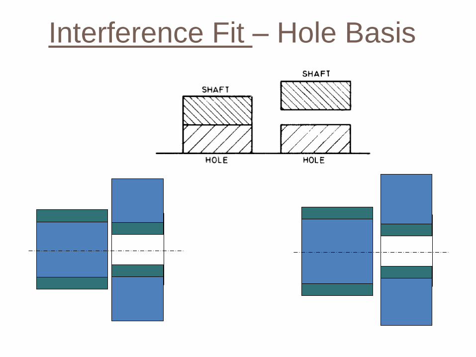
Interference Fit – Hole Basis
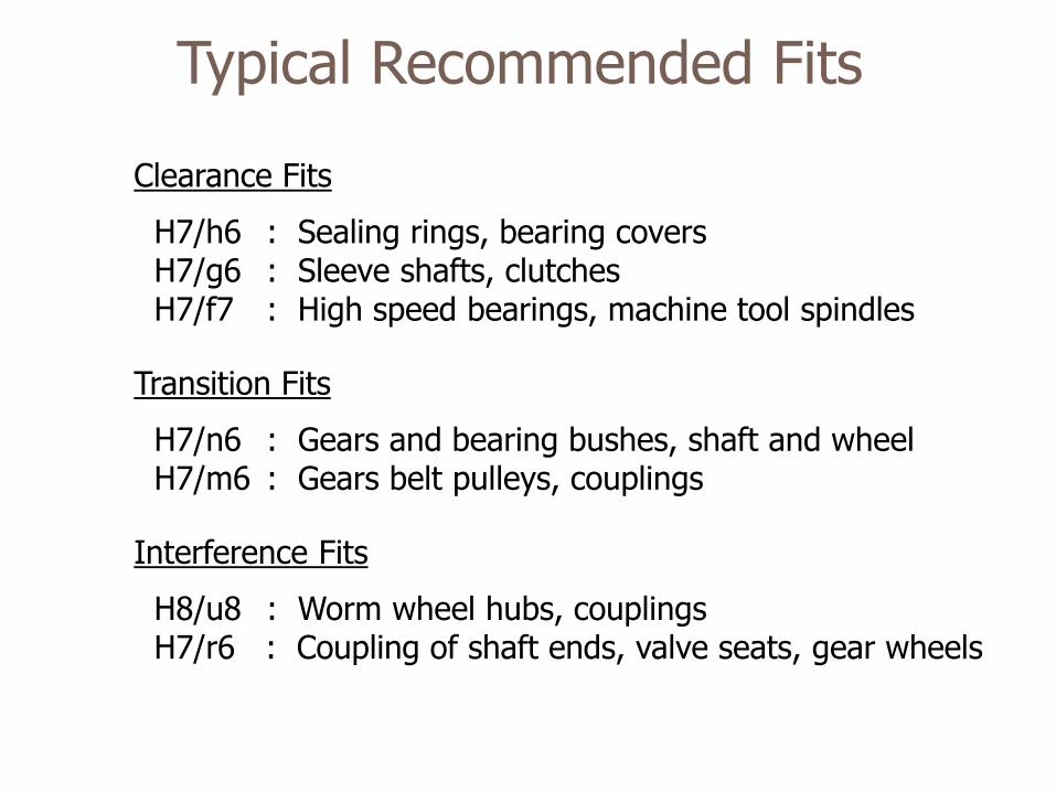
Typical Recommended Fits
Clearance Fits
H7/h6 : Sealing rings, bearing covers H7/g6 : Sleeve shafts, clutches H7/f7 : High speed bearings, machine tool spindles
Transition Fits
H7/n6 : Gears and bearing bushes, shaft and wheel H7/m6 : Gears belt pulleys, couplings
Interference Fits
H8/u8 : Worm wheel hubs, couplings H7/r6 : Coupling of shaft ends, valve seats, gear wheels
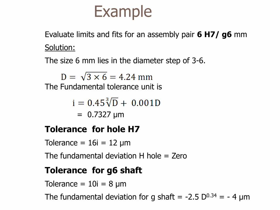
Example
Evaluate limits and fits for an assembly pair 6 H7/ g6 mm
Solution:
The size 6 mm lies in the diameter step of 3-6.
The Fundamental tolerance unit is
= 0.7327 μm
Tolerance for hole H7
Tolerance = 16i = 12 μm
The fundamental deviation H hole = Zero
Tolerance for g6 shaft
Tolerance = 10i = 8 μm
The fundamental deviation for g shaft = -2.5 D0.34 = - 4 μm
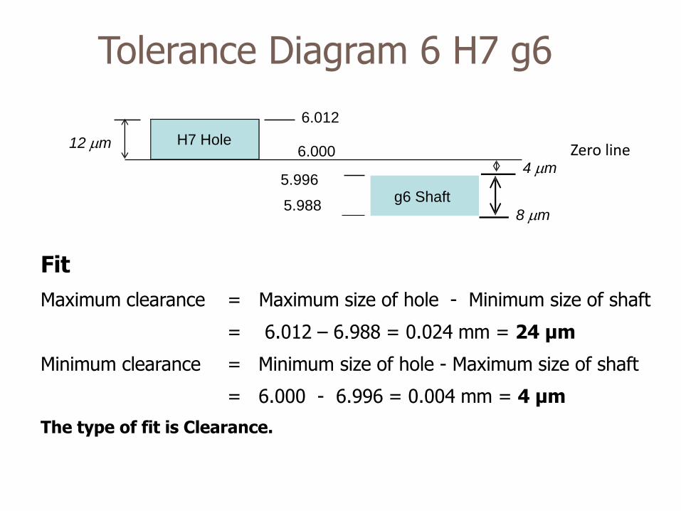
Fit
Maximum clearance = Maximum size of hole - Minimum size of shaft
= 6.012 – 6.988 = 0.024 mm = 24 μm
Minimum clearance = Minimum size of hole - Maximum size of shaft
= 6.000 - 6.996 = 0.004 mm = 4 μm
The type of fit is Clearance.
6.000 H7 Hole
4 m
12 m
5.996
5.988 8 m
6.012
Zero line
g6 Shaft
Tolerance Diagram 6 H7 g6
Objective
• Check if the part size is within the Upper and Lower size Limits
• Go gage should always go (into the part).
• NoGo gage should NOT go.
• Go gage should check both part Form and Dimension.
Go-NoGo Limit Gages
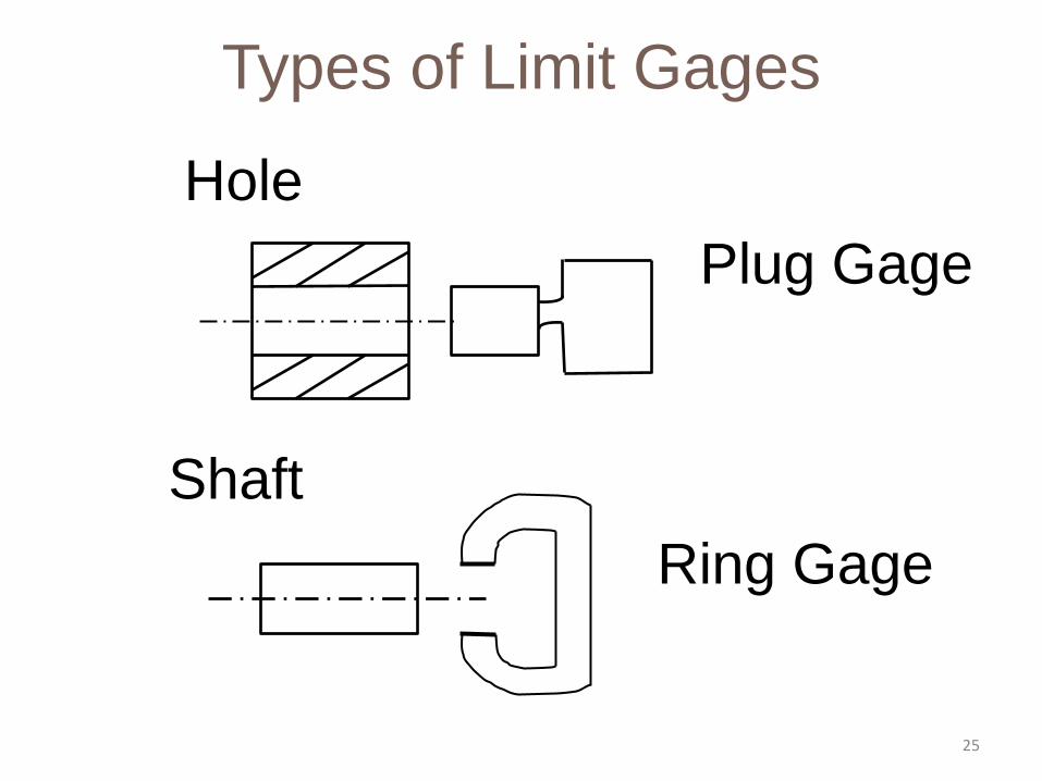
Types of Limit Gages
Hole
Plug Gage
Shaft
Ring Gage
25
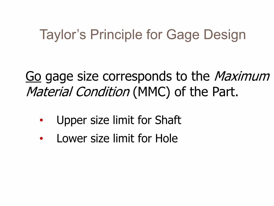
Go gage size corresponds to the Maximum Material Condition (MMC) of the Part.
• Upper size limit for Shaft
• Lower size limit for Hole
Taylor’s Principle for Gage Design
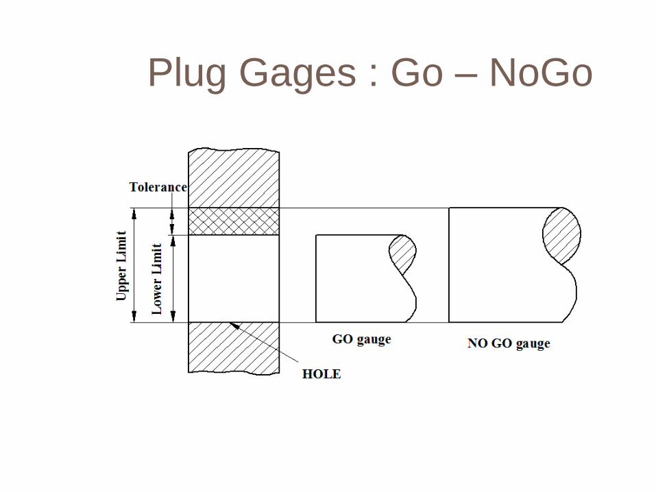
Plug Gages : Go – NoGo
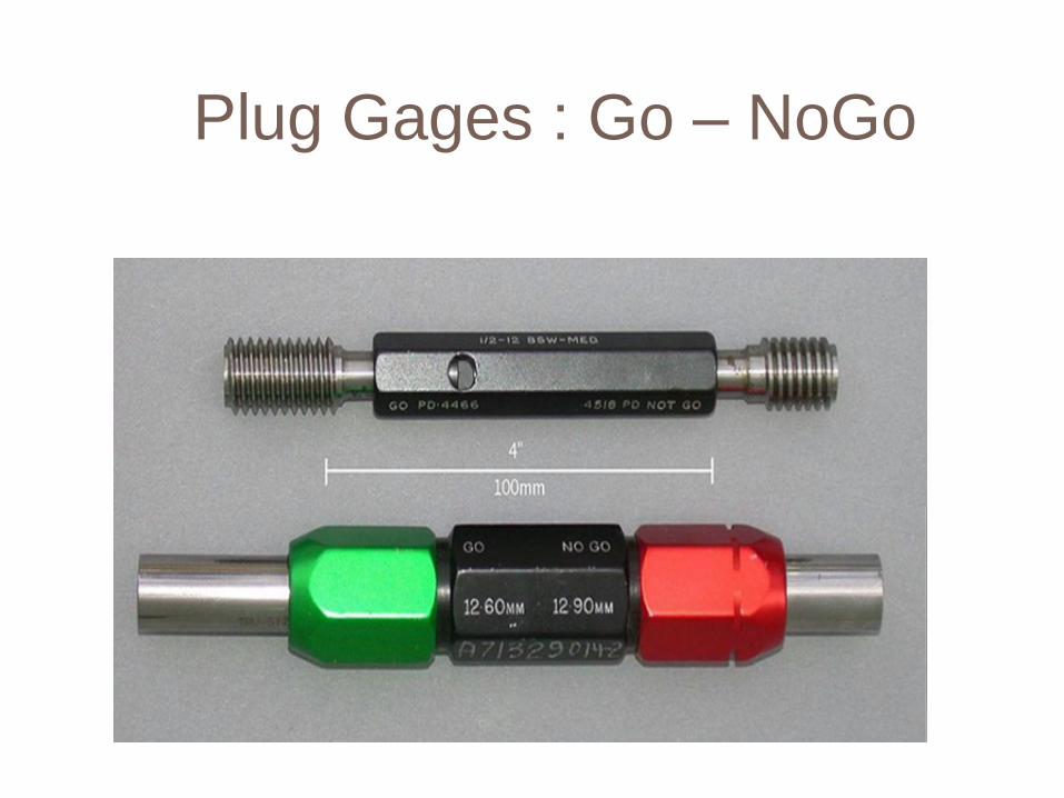
Plug Gages : Go – NoGo
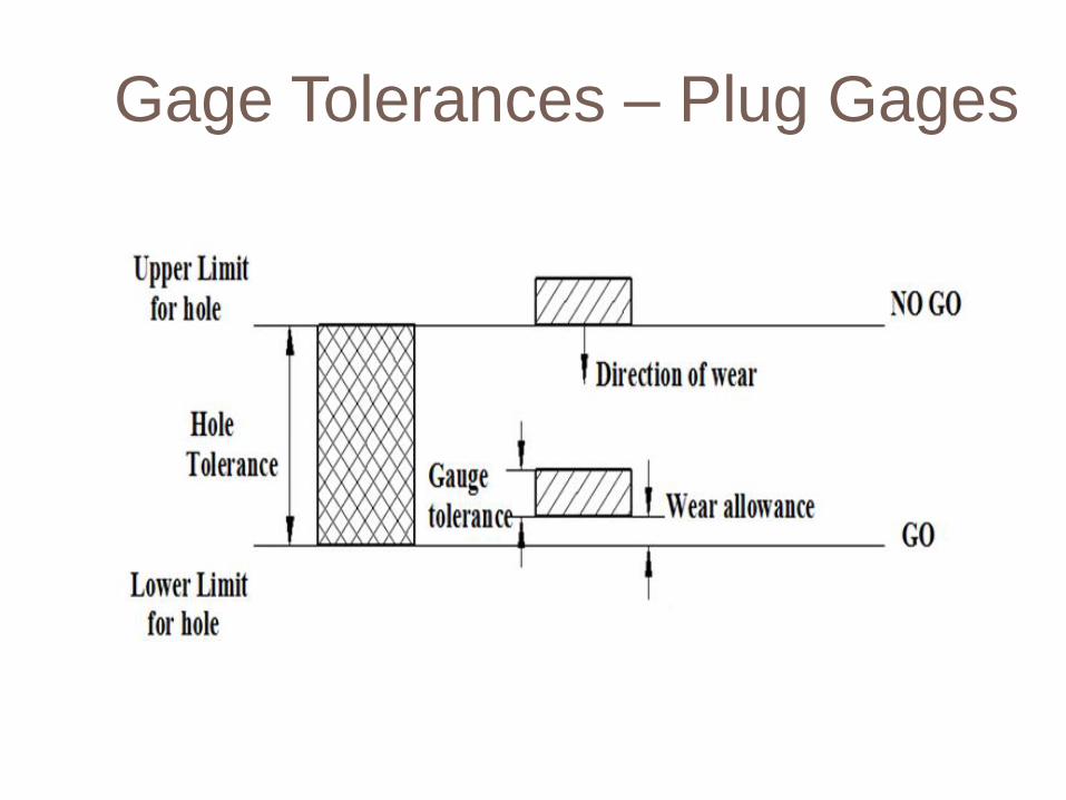
Gage Tolerances – Plug Gages
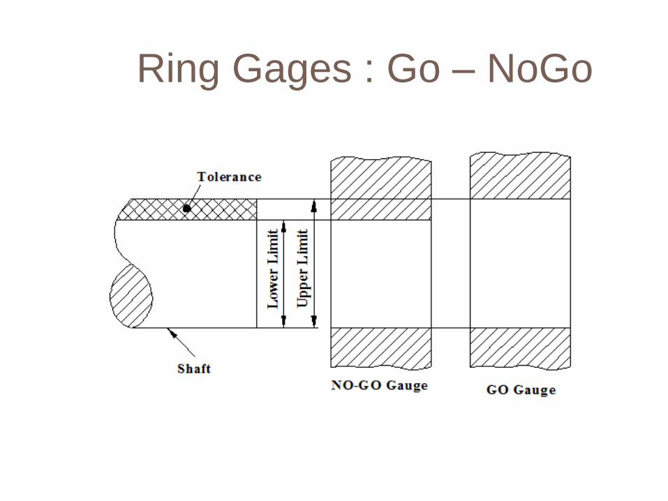
Ring Gages : Go – NoGo
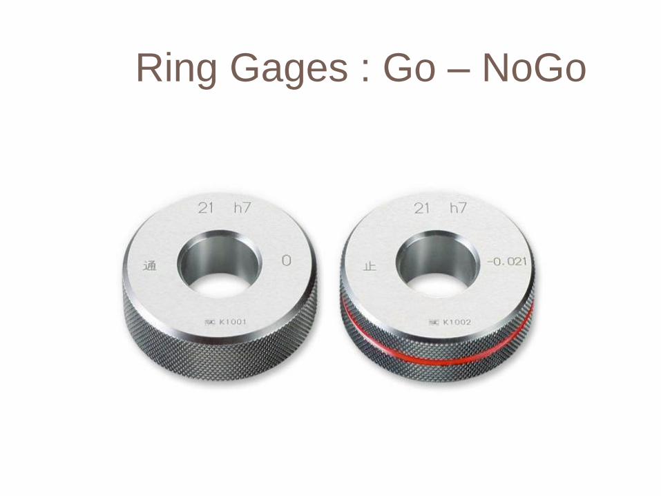
Ring Gages : Go – NoGo