Limits and methods of measurement of radio characteristics...
50
BRITISH STANDARD BS EN 55015:2001 Incorporating Amendments Nos. 1, 2 and Corrigendum No. 1 Limits and methods of measurement of radio disturbance characteristics of electrical lighting and similar equipment The European Standard EN 55015:2000, with the incorporation of amendment A1:2001 and A2:2002, has the status of a British Standard ICS 29.140.01; 33.100.10 Licensed Copy: Institute Of Technology Tallaght, Institute of Technology, Fri Aug 25 11:35:09 BST 2006, Uncontrolled Copy, (c) BSI
Transcript of Limits and methods of measurement of radio characteristics...

BRITISH STANDARD BS EN 55015:2001Incorporating Amendments Nos. 1, 2 and Corrigendum No. 1
Limits and methods of measurement of radio disturbance characteristics of electrical lighting and similar equipment
The European Standard EN 55015:2000, with the incorporation of amendment A1:2001 and A2:2002, has the status of a British Standard
ICS 29.140.01; 33.100.10
Lice
nsed
Cop
y: In
stitu
te O
f Tec
hnol
ogy
Tal
lagh
t, In
stitu
te o
f Tec
hnol
ogy,
Fri
Aug
25
11:3
5:09
BS
T 2
006,
Unc
ontr
olle
d C
opy,
(c)
BS
I

BS EN 55015:2001
This British Standard, having been prepared under the direction of the Electrotechnical Sector Policy and Strategy Committee, was published under the authority of the Standards Policy and Strategy Committee on 15 March 2001
© BSI 19 February 2002
ISBN 0 580 36888 2
National forewordThis British Standard is the official English language version of EN 55015:2000, including amendment A1:2001 and amendment A2:2002. It is identical with CISPR 15:2000 including amendment 1:2001 and 2:2002. It supersedes BS EN 55015:1996 which will be withdrawn on 2003-08-01
The start and finish of text introduced or altered by amendment is indicated in the text by tags !". Tags indicating changes to IEC text carry the number of the IEC amendment. For example, text altered by IEC amendment 1 is indicated by !".
The UK participation in its preparation was entrusted by Technical Committee GEL/210, EMC policy, to Subcommittee GEL/210/11, EMC products, which has the responsibility to:
A list of organizations represented on this subcommittee can be obtained on request to its secretary.
Cross-referencesThe British Standards which implement international or European publications referred to in this document may be found in the BSI Catalogue under the section entitled “International Standards Correspondence Index”, or by using the “Search” facility of the BSI Electronic Catalogue or of British Standards Online.This publication does not purport to include all the necessary provisions of a contract. Users of this publication are responsible for its correct application.Compliance with a British Standard does not of itself confer immunity from legal obligations.
— aid enquirers to understand the text;
— present to the responsible international/European committee any enquiries on the interpretation, or proposals for change, and keep the UK interests informed;
— monitor related international and European developments and promulgate them in the UK.
Summary of pagesThis document comprises a front cover, an inside front cover, the EN title page, pages 2 to 46, an inside back cover and a back cover.The BSI copyright date displayed in this document indicates when thedocument was last issued.
Amendments issued since publication
Amd. No. Date Comments
13716 4 July 2002 See national foreword
14024 Corrigendum No. 1
16 August 2002 Correction to the incorporation of Amendment No. 1
14943 19 February 2004 See national forewordLice
nsed
Cop
y: In
stitu
te O
f Tec
hnol
ogy
Tal
lagh
t, In
stitu
te o
f Tec
hnol
ogy,
Fri
Aug
25
11:3
5:09
BS
T 2
006,
Unc
ontr
olle
d C
opy,
(c)
BS
I

EUROPEAN STANDARD
NORME EUROÉENNE
EUROPÄISCHE NORM
EN 55015October 2000
+ A1December 2001
+ A2October 2002
ICS 33.100.10 Supersedes EN 55015:1996 + A1:1997 + A2:1999
English version
Limits and methods of measurement of radio disturbance characteristics of electrical lighting and similar equipment
(includes amendment A1:2001 and A2:2002)(CISPR 15:2000)
Limites et méthodes de mesure des perturbations radioélectriques produites par les appareils electriques d’clairage et les appareils analogues(inclut l’amendement A1:2001 et A2:2002)(CISPR 15:2000)
Grenzwerte und Messverfahren für die Funkstreigenschaften von elektrischen Beleuchtungsienrichtungen und ähnlichen Elektorgerten(enthält Änderung A1:2001 und A2:2002)(CISPR 15:2000)
This European Standard was approved by CENELEC on 2000-08-01.Amendment A1 was approved by CENELEC on 2001-12-01. Amendment 2 wasapproved by CENELEC on 2002-10-01. CENELEC members are bound tocomply with the CEN/CENELEC Internal Regulations which stipulate theconditions for giving this European Standard the status of a national standardwithout any alteration.
Up-to-date lists and bibliographical references concerning such nationalstandards may be obtained on application to the Central Secretariat or to anyCENELEC member.
This European Standard exists in three official versions (English, French,German). A version in any other language made by translation under theresponsibility of a CENELEC member into its own language and notified to theCentral Secretariat has the same status as the official versions.
CENELEC members are the national electrotechnical committees of Austria,Belgium, Czech Republic, Denmark, Finland, France, Germany, Greece,Hungary, Iceland, Ireland, Italy, Luxembourg, Malta, Netherlands, Norway,Portugal, Slovakia, Spain, Sweden, Switzerland and United Kingdom.
CENELECEuropean Committee for Electrotechnical Standardization
Comité Européen de Normalisation ElectrotechniqueEuropäisches Komitee für Elektrotechnische Normung
Central Secretariat: rue de Stassart 35, B-1050 Brussels
© 2000 CENELEC - All rights of exploitation in any form and by any means reserved worldwide for CENELEC members. Ref. No. EN 55015:2000 + A1:2001 + A2:2002 E
Lice
nsed
Cop
y: In
stitu
te O
f Tec
hnol
ogy
Tal
lagh
t, In
stitu
te o
f Tec
hnol
ogy,
Fri
Aug
25
11:3
5:09
BS
T 2
006,
Unc
ontr
olle
d C
opy,
(c)
BS
I

Foreword
The text of document CISPR/F/303/FDIS, future edition 6 of CISPR 15, prepared by CISPR SC F, Interference relating to household appliances, tools lighting equipment and similar apparatus, was submitted to the IEC-CENELEC as EN 55015 on 2000-08-01. This European Standard supersedes EN 55015:1996 and its amendments A1:1997 and A2:1999. The following dates were fixed:
— latest date by which the EN has to be implemented at national level by publication of an identical national standard or by endorsement
(dop) 2001-05-01
— latest date by which the national standards conflicting with EN have to withdrawn
(dow) 2003-08-01
Annexes designated “normative” are part of the body of the standard. In this standard, annexes A and ZA are normative. Annex ZA has been added by CENELEC.
__________
Endorsement notice
The text of the International Standard CISPR 15:2000 was approved by CENELEC as a European Standard without any modification.
__________
Foreword to amendment A1
The text of document CISPR/F/337/FDIS, future amendment 1 to CISPR 15:2000, prepared by CISPR SC F, Interference relating to household appliances, tools lighting equipment and similar apparatus, was submitted to the IEC-CENELEC parallel vote and was approved by CENELEC as amendment A1 to EN 55015:2000 on 2001-12-01. The following dates were fixed:
— latest date by which the amendment has to be implemented at national level by publication of an identical national standard or by endorsement
(dop) 2002-09-01
— latest date by which the national standards conflicting with the amendment have to withdrawn
(dow) 2004-12-01
Annexes designated “normative” are part of the body of the standard. In this amendment, Annex ZA is normative. Annex ZA has been added by CENELEC.
__________
Endorsement notice
The text of amendment 1:2001 to the International Standard CISPR 15:2000 was approved by CENELEC as an amendment to the European Standard without any modification.
__________
2 egaP0002:51055 NE
Page 2EN 55015:2000
Lice
nsed
Cop
y: In
stitu
te O
f Tec
hnol
ogy
Tal
lagh
t, In
stitu
te o
f Tec
hnol
ogy,
Fri
Aug
25
11:3
5:09
BS
T 2
006,
Unc
ontr
olle
d C
opy,
(c)
BS
I

Foreword to amendment A2 The text of document CISPR/F/356/FDIS, future amendment 2 to CISPR 15:2000, prepared by CISPR SC F, Interference relating to household appliances, tools, lighting equipment and similar apparatus, was submitted to the IEC-CENELEC parallel vote and was approved by CENELEC as amendment A2 to EN 55015:2000 on 2002-10-01. The following dates were fixed:
— latest date by which the amendment has to be implemented at national level by publication of an identical national standard or by endorsement
(dop) 2003-07-01
— latest date by which the national standards conflicting with the amendment have to withdrawn
(dow) 2005-10-01
xennAse sed“ detangironm”evita rarap efo t ydob eht fo s ehttradna.d siht nI mamdnexennA ,tne ZA si ronm.evita xennA ZA sah yb dedda neeb .CELENEC
__________
eciton tnemesrodnE
Txet eht fo mamdneretnI eht ot 2002:2 tneradnatS lanoitanw 0002:51 RPSIC dsa rppayb devo sa CELENEC ma namdneruE eht ot tneradnatS naepow diyna tuoht mfidoicnoita.
3 egaP0002:51055 NE
weroFA tnemdnema ot dro2 Tet ehxt fo odcum/RPSIC tneF3/65/FD,SI futura emdnemp ,0002:51 RPSIC ot 2 tneraperyb de CS RPSIC F, etnIrfernece ruoh ot gnitalesdlohe nailppacessloot ,, piuqe gnithgilmdna tne simrali rappasutaw ,sa smbu-CEI eht ot dettiCELENEC rapw dna etov lellasa rppayb devo sa CELENEC mamdne-2002 no 0002:51055 NE ot 2A tne-01.10 Tf ehwolloisetad gn wref eix:de
— setalt yb etad wcihma eht hmdnesah tne eb ot mimelpyb level lanoitan ta detne cilbupfo noita na citnedis lanoitan latradnaro d yb rodnesmetne
()pod -3002-7010
— setalt yb etad wcihs lanoitan eht htradnasd cfnocilgnit wima eht htmdnew ot evah tneirdhtwan
(wod) -5002-0110
Annexes designated “normative” are part of the body of the standard. In this amendment, Annex ZA is normative. Annex ZA has been added by CENELEC.
__________
Endorsement notice
The text of amendment 2:2002 to the International Standard CISPR 15:2000 was approved by CENELEC as an amendment to the European Standard without any modification.
Page 3EN 55015:2000
Page 3EN 55015:2000
Lice
nsed
Cop
y: In
stitu
te O
f Tec
hnol
ogy
Tal
lagh
t, In
stitu
te o
f Tec
hnol
ogy,
Fri
Aug
25
11:3
5:09
BS
T 2
006,
Unc
ontr
olle
d C
opy,
(c)
BS
I

CONTENTS
Page
1 Scope ...............................................................................................................................7 2 Normative references........................................................................................................8 3 Definitions ........................................................................................................................8 4 Limits ...............................................................................................................................8
4.1 Frequency ranges ....................................................................................................8 4.2 Insertion loss ...........................................................................................................9 4.3 Disturbance voltages ...............................................................................................9
4.3.1 Mains terminals ...........................................................................................9 4.3.2 Load and control terminals ......................................................................... 10 4.3.3 Control terminals ....................................................................................... 10
4.4 Radiated electromagnetic disturbances .................................................................. 10 5 Application of the limits ................................................................................................... 11
5.1 General ................................................................................................................. 11 5.2 Indoor luminaires ................................................................................................... 11
5.2.1 General ..................................................................................................... 11 5.2.2 Incandescent lamp luminaires .................................................................... 11 5.2.3 Fluorescent lamp luminaires ...................................................................... 12 5.2.4 Other luminaires ........................................................................................ 12
5.3 Independent auxiliaries exclusively for use with lighting equipment ......................... 12 5.3.1 General ..................................................................................................... 12 5.3.2 Independent light regulating devices .......................................................... 12 5.3.3 Independent transformers and convertors for incandescent lamps .............. 13 5.3.4 Independent ballasts for fluorescent and other discharge lamps ................. 13 5.3.5 Semi-luminaires ......................................................................................... 13 5.3.6 Independent starters and igniters ............................................................... 13
5.4 Self-ballasted lamps .............................................................................................. 14 5.5 Outdoor lighting appliances.................................................................................... 14
5.5.1 General ..................................................................................................... 14 5.5.2 Mounting system........................................................................................ 14 5.5.3 Integrated switching devices ...................................................................... 14 5.5.4 Incandescent lamp luminaires .................................................................... 14 5.5.5 Fluorescent lamp luminaires ...................................................................... 14 5.5.6 Other luminaires ........................................................................................ 15
5.6 UV and IR radiation appliances .............................................................................. 15 5.6.1 General ..................................................................................................... 15 5.6.2 IR radiation appliances .............................................................................. 15 5.6.3 UV fluorescent lamp appliances ................................................................. 15 5.6.4 Other UV and/or IR appliances................................................................... 15
5.7 Transport lighting................................................................................................... 16 5.7.1 General ..................................................................................................... 16 5.7.2 External lighting and signalling ................................................................... 16 5.7.3 Lighting of on-board instruments ................................................................ 16 5.7.4 Lighting of interior cabins and rooms.......................................................... 16
5.8 Neon and other advertising signs ........................................................................... 16 5.9 Self-contained emergency lighting luminaires ......................................................... 16
5.9.1 General ..................................................................................................... 16 5.9.2 Measurement in the mains on mode, i.e. operating condition prior to
the disruption of the mains supply .............................................................. 17
4 egaP0002:51055 NE
Page 4EN 55015:2000
Lice
nsed
Cop
y: In
stitu
te O
f Tec
hnol
ogy
Tal
lagh
t, In
stitu
te o
f Tec
hnol
ogy,
Fri
Aug
25
11:3
5:09
BS
T 2
006,
Unc
ontr
olle
d C
opy,
(c)
BS
I

5.9.3 Measurement in emergency mode, i.e. operating condition after
disruption of the mains supply .................................................................... 17 5.10 Replaceable starters for fluorescent lamps............................................................. 17
6 Operating conditions for lighting equipment ..................................................................... 17 6.1 General ................................................................................................................. 17 6.2 Lighting equipment ................................................................................................ 17 6.3 Supply voltage and frequency ................................................................................ 17 6.4 Ambient conditions ................................................................................................ 18 6.5 Lamps ................................................................................................................... 18
6.5.1 Type of lamp used ..................................................................................... 18 6.5.2 Ageing time of lamps ................................................................................. 18 6.5.3 Stabilization time of lamps ......................................................................... 18
6.6 Replaceable starters .............................................................................................. 18 7 Method of insertion loss measurement ............................................................................ 18
7.1 Circuits for the measurement of insertion loss ........................................................ 18 7.2 Measuring arrangement and procedure .................................................................. 19
7.2.1 Radiofrequency generator .......................................................................... 19 7.2.2 Balance-to-unbalance transformer ............................................................. 19 7.2.3 Measuring receiver and network................................................................. 19 7.2.4 Dummy lamps............................................................................................ 19 7.2.5 Measuring arrangements ........................................................................... 20
7.3 Luminaire .............................................................................................................. 20 7.4 Measurement procedure ........................................................................................ 20
8 Method of measurement of disturbance voltages ............................................................. 21 8.1 Measuring arrangement and procedure .................................................................. 21
8.1.1 Mains terminal voltage measurement ......................................................... 21 8.1.2 Load terminal voltage measurement........................................................... 21 8.1.3 Control terminal voltage measurement ....................................................... 21 8.1.4 Light regulation .......................................................................................... 21 8.1.5 Measurements with an average detector .................................................... 22
8.2 Indoor and outdoor luminaires................................................................................ 22 8.3 Independent light regulating devices ...................................................................... 23
8.3.1 Directly operating devices .......................................................................... 23 8.3.2 Devices having a remote control function ................................................... 23
8.4 Independent transformers and convertors for incandescent lamps.......................... 23 8.5 Independent ballasts for fluorescent and other discharge lamps ............................. 24 8.6 Self-ballasted lamps and semi-luminaires .............................................................. 24 8.7 UV and IR radiation appliances .............................................................................. 25 8.8 Self-contained emergency lighting luminaires ......................................................... 25 8.9 Independent starters and igniters for fluorescent and other discharge lamps .......... 25
9 Method of measurement of radiated electromagnetic disturbances .................................. 25 9.1 Measuring arrangement and procedure .................................................................. 25
9.1.1 Measuring equipment................................................................................. 25 9.1.2 Measurements in three directions............................................................... 25 9.1.3 Wiring instructions ..................................................................................... 26 9.1.4 Light regulation .......................................................................................... 26
9.2 Indoor and outdoor luminaires................................................................................ 26
5 egaP0002:51055 NE
Page 5EN 55015:2000
Lice
nsed
Cop
y: In
stitu
te O
f Tec
hnol
ogy
Tal
lagh
t, In
stitu
te o
f Tec
hnol
ogy,
Fri
Aug
25
11:3
5:09
BS
T 2
006,
Unc
ontr
olle
d C
opy,
(c)
BS
I

9.3 Independent convertors for incandescent lamps ..................................................... 26 9.4 Independent ballasts for fluorescent and other discharge lamps ............................. 26 9.5 Self-ballasted lamps and semi-luminaires .............................................................. 26 9.6 UV and IR radiation appliances .............................................................................. 26 9.7 Self-contained emergency lighting luminaires ......................................................... 26
10 Interpretation of CISPR radio disturbance limits .............................................................. 26 10.1 Significance of a CISPR limit ................................................................................. 26 10.2 Tests .....................................................................................................................27 10.3 Statistical method of evaluation.............................................................................. 27 10.4 Banning of sales .................................................................................................... 28
Annex A (normative) Electrical and constructional requirements for the low-capacitance balance-to-unbalance transformer ..........................................................41
Annex ZA (normative) Normative references to international publications with their corresponding European publications ................................................................................................... 46
Figure 1 – Insertion loss measurement on linear and U-type fluorescent lamp luminaires....................29 Figure 2 – Insertion loss measurement on circular fluorescent lamp luminaires ......................30 Figure 3 – Insertion loss measurement on luminaires for single-capped fluorescent lamps with integrated starter .................................................................................................31 Figure 4a – Configuration of linear and U-type dummy lamps.................................................32 Figure 4b – Configuration of circular dummy lamps................................................................33 Figure 4c – Dummy lamp for 15 mm fluorescent lamps .........................................................34 Figure 4d – Dummy lamp for 15 mm single-capped fluorescent lamps ...................................35 Figure 4e – Dummy lamp for single-capped fluorescent lamps, linear-shaped, twin tube, tube diameter 12 mm ............................................................................................................36 Figure 4f – Dummy lamp for single-capped fluorescent lamps, linear-shaped, quad tube, diameter 12 mm ....................................................................................................................37 Figure 5 – Measuring arrangements for an independent light regulating device, transformer or convertor........................................................................................................38 Figure 6 – Measuring arrangements for measuring a luminaire (figure 6a), an independent ballast (figure 6b) and a self-ballasted lamp (figure 6c) ......................................39 Figure 7 – Conical metal housing for self-ballasted fluorescent lamps ....................................40 Figure A.1 – Isolation test configuration .................................................................................42 Figure A.2a – Balance-to-unbalance transformer circuit .........................................................43 Figure A.2b – Details of transformer core construction...........................................................44 Figure A.2c – Details of transformer core construction ...........................................................44 Figure A.2d – Construction of transformer .............................................................................45
Table 1 – Minimum values of insertion loss..............................................................................9 Table 2a – Disturbance voltage limits at mains terminals .........................................................9 Table 2b – Disturbance voltage limits at load terminals ..........................................................10 Table 2c – Disturbance voltage limits at control terminals ......................................................10 Table 3 – Radiated electromagnetic disturbance limits...........................................................11 Table 4 – Sample size and corresponding k factor in a non-central t-distribution ....................27
6 egaP0002:51055 NE
Page 6EN 55015:2000
Lice
nsed
Cop
y: In
stitu
te O
f Tec
hnol
ogy
Tal
lagh
t, In
stitu
te o
f Tec
hnol
ogy,
Fri
Aug
25
11:3
5:09
BS
T 2
006,
Unc
ontr
olle
d C
opy,
(c)
BS
I

LIMITS AND METHODS OF MEASUREMENT OF RADIO DISTURBANCE CHARACTERISTICS OF ELECTRICAL LIGHTING
AND SIMILAR EQUIPMENT
1 Scope
This standard applies to the emission (radiated and conducted) of radiofrequency disturbances from:
– all lighting equipment with a primary function of generating and/or distributing light intended for illumination purposes, and intended either for connection to the low voltage electricity supply or for battery operation;
– the lighting part of multi-function equipment where one of the primary functions of this is illumination;
– independent auxiliaries exclusively for use with lighting equipment; – UV and IR radiation equipment; – neon advertising signs; – street/flood lighting intended for outdoor use; – transport lighting (installed in buses and trains).
Excluded from the scope of this standard are:
– lighting equipment operating in the ISM frequency bands (as defined in Resolution 63 (1979) of the ITU Radio Regulation);
– lighting equipment for aircraft and airports; – apparatus for which the electromagnetic compatibility requirements in the radio-frequency
range are explicitly formulated in other IEC or CISPR standards.
NOTE – Examples are:
NOTE – built-in lighting devices in other equipment, for example scale illumination or neon devices;
NOTE – photocopiers;
NOTE – slide projectors;
NOTE – lighting equipment for road vehicles.
The frequency range covered is 9 kHz to 400 GHz.
Multi-function equipment which is subjected simultaneously to different clauses of this standard and/or other standards shall meet the provisions of each clause/standard with the relevant functions in operation.
The limits in this standard have been determined on a probabilistic basis to keep the suppression of disturbances within economically reasonable limits while still achieving an adequate level of radio protection and electromagnetic compatibility. In exceptional cases, additional provisions may be required.
7 egaP0002:51055 NE
Page 7EN 55015:2000
Lice
nsed
Cop
y: In
stitu
te O
f Tec
hnol
ogy
Tal
lagh
t, In
stitu
te o
f Tec
hnol
ogy,
Fri
Aug
25
11:3
5:09
BS
T 2
006,
Unc
ontr
olle
d C
opy,
(c)
BS
I
2 Normative references
The following normative documents contain provisions which, through reference in this text, constitute provisions of this International Standard. For dated references, subsequent amendments to, or revisions of, any of these publications do not apply. However, parties to agreements based on this International Standard are encouraged to investigate the possibility of applying the most recent editions of the normative documents indicated below. For undated references, the latest edition of the normative document referred to applies. Members of IEC and ISO maintain registers of currently valid International Standards.
IEC 60050(161):1990, International Electrotechnical Vocabulary (IEV) – Chapter 161: Electromagnetic compatibility
IEC 60155:1993, Glow-starters for fluorescent lamps
IEC 60598: Luminaires
CISPR 11:1997, Industrial, scientific and medical (ISM) radio-frequency equipment – Electromagnetic disturbance characteristics – Limits and methods of measurement
CISPR 16-1:1999, Specification for radio disturbance and immunity measuring apparatus and methods – Part 1: Radio disturbance and immunity measuring apparatus
!CISPR 16-2:1996, Specification for radio disturbance and immunity measuring apparatus and methods — Part 2: Methods of measurement of disturbances and immunity CISPR 22:1997, Information technology equipment — Radio disturbance characteristics — Limits and methods of measurement "
3 Definitions
For the purpose of this International Standard, the definitions contained in IEC 60050(161) apply.
Continuous disturbance may be either broadband, for instance caused by the switching operations or by unstable gas-discharges in the lamp electrode region, or may be narrowband, for instance caused by electronic control devices operating at dedicated frequencies.
NOTE Instead of the concept of "broadband" and "narrowband", a distinction is made in this standard between two related kinds of disturbance, defined by the type of the applied detector. For this purpose, limits have been defined with respect to the measurement with the quasi-peak detector and with the average detector. By using this approach, a combination of broadband and narrowband disturbances can also be assessed.
4 Limits
4.1 Frequency ranges
In 4.2, 4.3 and 4.4, limits are given as a function of frequency range. No measurements need to be performed at frequencies where no limits are specified.
NOTE The World Administrative Radiocommunications Conference (WARC) has in 1979 reduced the lower frequency limit in region 1 to 148,5 kHz; for applications falling within the scope of this standard, tests at 150 kHz are considered adequate, since 148,5 kHz falls within the receiver bandwidth.
Page8 0002:51055 NE
Page 8EN 55015:2000
Lice
nsed
Cop
y: In
stitu
te O
f Tec
hnol
ogy
Tal
lagh
t, In
stitu
te o
f Tec
hnol
ogy,
Fri
Aug
25
11:3
5:09
BS
T 2
006,
Unc
ontr
olle
d C
opy,
(c)
BS
I
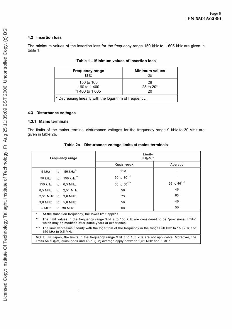
4.2 Insertion loss
The minimum values of the insertion loss for the frequency range 150 kHz to 1 605 kHz are given in table 1.
Table 1 – Minimum values of insertion loss
Frequency range kHz
Minimum values dB
150 to 160 160 to 1 400
1 400 to 1 605
28 28 to 20*
20
* Decreasing linearly with the logarithm of frequency.
4.3 Disturbance voltages
4.3.1 Mains terminals
The limits of the mains terminal disturbance voltages for the frequency range 9 kHz to 30 MHz are given in table 2a.
Table 2a – Disturbance voltage limits at mains terminals
Frequency range
Limits dB(µV)*
Quasi-peak Average
9 kHz to 50 kHz**
50 kHz to 150 kHz**
150 kHz to 0,5 MHz
0,5 MHz to 2,51 MHz
2,51 MHz to 3,0 MHz
3,0 MHz to 5,0 MHz
5 MHz to 30 MHz
110
90 to 80***
66 to 56***
56
73
56
60
–
–
56 to 46***
46
63
46
50
* At the transition frequency, the lower limit applies. ** The limit values in the frequency range 9 kHz to 150 kHz are considered to be "provisional limits"
which may be modified after some years of experience. *** The limit decreases linearly with the logarithm of the frequency in the ranges 50 kHz to 150 kHz and
150 kHz to 0,5 MHz.
NOTE In Japan, the limits in the frequency range 9 kHz to 150 kHz are not applicable. Moreover, the limits 56 dB(µV) quasi-peak and 46 dB(µV) average apply between 2,51 MHz and 3 MHz.
Page 90002:51055 NE
Page 9EN 55015:2000
Lice
nsed
Cop
y: In
stitu
te O
f Tec
hnol
ogy
Tal
lagh
t, In
stitu
te o
f Tec
hnol
ogy,
Fri
Aug
25
11:3
5:09
BS
T 2
006,
Unc
ontr
olle
d C
opy,
(c)
BS
I

! 4.3.2 Load terminals
The limits of the load terminal disturbance voltage for the frequency range 150 kHz to 30 MHz are given in table 2b. "
!Table 2b – Disturbance voltage limits at load terminals "
Frequency range
Limits dB(µV)*
MHz Quasi-peak Average
0,15 to 0,50 0,50 to 30
80 74
70 64
* At the transition frequency, the lower limit applies. ! 4.3.3 Control terminals
The limits of the control terminal disturbance voltage for the frequency range 150 kHz to 30 MHz are given in table 2c.
Table 2c – Disturbance voltage limits at control terminals
Limits
dB(µV)
Frequency range
MHz
Quasi-peak Average
0,15 to 0,50 0,50 to 30
84 to 74 74
74 to 64 64
NOTE 1 The limits decrease linearly with the logarithm of the frequency in the range 0,15 MHz to 0,5 MHz.
NOTE 2 The voltage disturbance limits are derived for use with an impedance stabilization network (ISN) which presents a common mode (asymmetric mode) impedance of 150 Ω to the control terminal.
"
4.4 Radiated electromagnetic disturbances
The quasi-peak limits of the magnetic component of the radiated disturbance field strength in the frequency range 9 kHz to 30 MHz, measured as a current in 2 m, 3 m or 4 m loop antennas around the lighting equipment, are given in table 3.
The limits for the 2 m loop diameter apply to equipment not exceeding a length of 1,6 m, those for the 3 m loop diameter for equipment having a length in between 1,6 m and 2,6 m and those for the 4 m loop diameter for equipment having a length in between 2,6 m and 3,6 m.
Page 10EN 55015:2000
Page 10EN 55015:2000
Lice
nsed
Cop
y: In
stitu
te O
f Tec
hnol
ogy
Tal
lagh
t, In
stitu
te o
f Tec
hnol
ogy,
Fri
Aug
25
11:3
5:09
BS
T 2
006,
Unc
ontr
olle
d C
opy,
(c)
BS
I

Table 3 – Radiated electromagnetic disturbance limits
Frequency range
Limits for loop diameter dB(µA)*
MHz 2 m 3 m 4 m
9 kHz to 70 kHz
70 kHz to 150 kHz
150 kHz to 2,2 MHz
2,2 MHz to 3,0 MHz
3,0 MHz to 30 MHz
88
88 to 58**
58 to 26**
58
22
81
81 to 51**
51 to 22**
51
15 to 16***
75
75 to 45**
45 to 16**
45
9 to 12***
NOTE * At the transition frequency, the lower limit applies. NOTE ** Decreasing linearly with the logarithm of the frequency. NOTE *** Increasing linearly with the logarithm of the frequency.
NOTE NOTE In Japan, the limits for frequencies 9 kHz to 150 kHz do not apply.
5 Application of the limits
5.1 General
Applications of the limits for the various kinds of lighting equipment as mentioned in the scope of this standard are given in 5.2 to 5.10.
No emission requirements apply to lamps other than self-ballasted lamps nor to auxiliaries incorporated in luminaires, in self-ballasted lamps or in semi-luminaires. (See, however, note 2 of 5.3.1 in this respect.)
The disturbance caused by manual or automatic operation of a switch (external or included in equipment) to connect or disconnect the mains shall be disregarded. This includes manual on/off switches or, for example, switches activated by sensors or ripple control receivers. However, switches which will be repeatedly operated (e.g. such as those of advertising signs) are not included in this exception.
5.2 Indoor luminaires
5.2.1 General
The following conditions apply to all kinds of indoor luminaires irrespective of the environment in which they are used.
5.2.2 Incandescent lamp luminaires
Incandescent lamp luminaires where the lamps are a.c. mains or d.c. operated, or which do not incorporate a light regulating device or electronic switch, are not expected to produce electromagnetic disturbances. Therefore, they are deemed to fulfil all relevant requirements of this standard without further testing.
NOTE Where, in this standard, the term "incandescent lamp" is used, all types of incandescent lamps including halogen lamps are meant.
Pa1 eg10002:51055 NE
Page 11EN 55015:2000
Lice
nsed
Cop
y: In
stitu
te O
f Tec
hnol
ogy
Tal
lagh
t, In
stitu
te o
f Tec
hnol
ogy,
Fri
Aug
25
11:3
5:09
BS
T 2
006,
Unc
ontr
olle
d C
opy,
(c)
BS
I

5.2.3 Fluorescent lamp luminaires
The minimum values of insertion loss of table 1 shall apply where a fluorescent lamp luminaire is a starter switch operated type and designed for one of the following lamp types:
– linear fluorescent lamps with a nominal diameter of 15 mm, 25 mm or 38 mm; – circular fluorescent lamps with a nominal diameter of 28 mm or 32 mm; – U-type fluorescent lamps with a nominal diameter of 15 mm, 25 mm or 38 mm; – single-capped fluorescent lamps, without integrated starter and with a nominal diameter of
15 mm; – single-capped fluorescent lamps, linear shaped, twin and quad tube, with integrated starter
and having a nominal tube diameter of 12 mm.
5.2.4 Other luminaires
Indoor luminaires other than described in 5.2.2 or 5.2.3 shall comply with the mains terminal voltage limits given in table 2a.
Where the luminaire supplies the lamp(s) with a current having an operation frequency in excess of 100 Hz, it shall comply with the radiated disturbance limits given in table 3.
!Where the light output of the luminaire is regulated by an external device with separate control lines, the disturbance voltage at the control terminals shall comply with the requirements of 4.3.3."
5.3 Independent auxiliaries exclusively for use with lighting equipment
5.3.1 General
Independent auxiliaries are electric or electronic devices designed to be applied external to a luminaire and to be used to control the current or voltage of a discharge or incandescent lamp. Examples are dimmers, transformers and convertors for lamps, ballasts for discharge lamps (including fluorescent lamps) and semi-luminaires for compact fluorescent lamps and for incandescent lamps.
NOTE 1 The requirements described in this subclause (5.3) are for the sole purpose of checking the electromagnetic emission characteristics of the auxiliary itself. Due to the variety of wiring circuits, it is impossible to describe requirements for the installation. In this respect, it is recommended that the manufacturer give guidelines for the proper use of the auxiliary.
NOTE 2 The requirements of this subclause (5.3) may be used for testing auxiliaries intended to be built into a luminaire. However, there is no obligation for such testing. Moreover, even when the auxiliary complies with the requirements of this subclause, the luminaire will always be tested.
5.3.2 Independent light regulating devices
5.3.2.1 Types of devices
There are two types of light regulating devices: those like dimmers which directly regulate the lamps, and those which have a remote control function to regulate the light output via a ballast or convertor.
5.3.2.2 Independent directly operating light regulating devices
Where such devices incorporate semiconductors, they shall comply with the terminal voltage limits given in tables 2a and 2b, otherwise no limits apply.
When several light regulating devices are contained in one product or enclosure, and when each individual device consists of an entirely self-contained regulating circuit (including all suppression components) and operates independently of the others (i.e. does not control, either by design or fortuitously, any load controlled by another individual regulator), then each device is tested separately.
Page21 0002:51055 NE
Page 12EN 55015:2000
Lice
nsed
Cop
y: In
stitu
te O
f Tec
hnol
ogy
Tal
lagh
t, In
stitu
te o
f Tec
hnol
ogy,
Fri
Aug
25
11:3
5:09
BS
T 2
006,
Unc
ontr
olle
d C
opy,
(c)
BS
I

5.3.2.3 Independent remote control devices Where such devices generate a d.c. or low-frequency (<500 Hz) control signal, no limits apply. For radiofrequency or infrared operating devices, this standard does not apply. !Other independent remote control devices shall comply with the requirements of 4.3.1 and 4.3.3." 5.3.3 Independent transformers and convertors for incandescent lamps
5.3.3.1 General
Transformers for incandescent lamps change only the voltage and do not convert the mains frequency, whereas convertors also convert the frequency. Both kinds of devices can incorporate means for regulating the light output of the lamps.
5.3.3.2 Independent transformers
For voltage transformers for incandescent lamps which do not regulate the voltage by means of active electronic components, the condition of 5.2.2 applies. Other independent transformers for incandescent lamps shall comply with the terminal voltage limits given in tables 2a and 2b.
5.3.3.3 Independent convertors
Independent electronic convertors for incandescent lamps shall either:
a) comply with the terminal voltage limits given in tables 2a and 2b; or, b) where the convertor has a non-detachable load supply cable, or where the manufacturer
gives strict installation instructions which define the position, type and maximum length of cable(s) to be connected to the lamp(s), then the convertor shall comply with the terminal voltage limits given in table 2a and with the radiated disturbance limits given in table 3, under these conditions.
5.3.4 Independent ballasts for fluorescent and other discharge lamps
5.3.4.1 Independent ballasts designed for a type of fluorescent lamp as mentioned in 5.2.3 and operated with starter shall comply with the minimum values of insertion loss given in table 1.
5.3.4.2 Other independent ballasts shall comply with the mains terminal voltage limits given in table 2a.
Where the ballast supplies the lamp with a current having a frequency in excess of 100 Hz, it shall comply with the radiated disturbance limits given in table 3.
!Where the light is regulated by an external device with separate control lines, the disturbance voltage at the control terminals shall comply with the requirements of 4.3.3." 5.3.5 Semi-luminaires
Semi-luminaires for compact fluorescent lamps and for incandescent lamps, sometimes called adaptors, are devices equipped, on the one side, with an Edison screw or bayonet cap to allow mounting in a standard incandescent lampholder and, on the other side, with a lampholder to allow the insertion of a replaceable light source.
Semi-luminaires shall comply with the terminal voltage limits given in table 2a.
Where the light source is operated at a frequency exceeding 100 Hz, the unit shall comply with the radiated disturbance limits given in table 3.
5.3.6 Independent starters and igniters
Independent starters and igniters for fluorescent and other discharge lamps are tested in a circuit as described in 8.9. They shall comply with the terminal voltage limits given in table 2a.
Page 13E0002:51055 N
Page 13EN 55015:2000
Lice
nsed
Cop
y: In
stitu
te O
f Tec
hnol
ogy
Tal
lagh
t, In
stitu
te o
f Tec
hnol
ogy,
Fri
Aug
25
11:3
5:09
BS
T 2
006,
Unc
ontr
olle
d C
opy,
(c)
BS
I

5.4 Self-ballasted lamps
For self-ballasted lamps, the ballasting and starting arrangements are encapsulated with the lamp into one single unit. These lamps are fitted with Edison screw or bayonet caps and can be inserted directly into an appropriate holder.
Self-ballasted lamps shall comply with the terminal voltage limits given in table 2a.
Where the light source is operated at a frequency exceeding 100 Hz, the unit shall comply with the radiated disturbance limits given in table 3.
5.5 Outdoor lighting appliances
5.5.1 General
For the purpose of this standard, the term "outdoor lighting" is used for the general lighting of public areas such as streets, walkways, cycle paths, motorways, tunnels, car parks, service stations and outdoor sports and recreational areas, for security and floodlighting of buildings and the like. Moreover, requirements described in this subclause (5.5) apply to the (outdoor) lighting appliances on private grounds, industrial estates and the like.
However, such lighting equipment may be subject to specific emission requirements which are not covered by this standard, for example airport lighting.
This subclause (5.5) does not apply to neon and other advertising signs.
5.5.2 Mounting system
Generally, an outdoor lighting appliance is built up of a support and one or more luminaires. The support could be:
– a pipe (bracket) or the like; – a mast (column) arm; – a post top; – a span or suspension wires; – a wall or ceiling.
Unless otherwise stated, the emission requirements described in this subclause (5.5) apply to the luminaire (including the lamp) and no requirements apply to the luminaire support.
5.5.3 Integrated switching devices
Disturbances caused by the operation of integrated switching devices such as ripple control receivers shall be disregarded.
5.5.4 Incandescent lamp luminaires
The condition of 5.2.2 applies.
5.5.5 Fluorescent lamp luminaires
Luminaires using a type of fluorescent lamp as mentioned in 5.2.3 and operating with a starter shall comply with the minimum values of insertion loss given in table 1.
41 egaP0002:51055 NE
Page 14EN 55015:2000
Lice
nsed
Cop
y: In
stitu
te O
f Tec
hnol
ogy
Tal
lagh
t, In
stitu
te o
f Tec
hnol
ogy,
Fri
Aug
25
11:3
5:09
BS
T 2
006,
Unc
ontr
olle
d C
opy,
(c)
BS
I

5.5.6 Other luminaires
Outdoor luminaires other than described in 5.5.4 or 5.5.5 shall comply with the mains terminal voltage limits given in table 2a.
Where the lamp(s) in the luminaire is (are) supplied with a current having a frequency in excess of 100 Hz, the electronic ballast shall be incorporated in the luminaire. The luminaire shall comply with the radiated disturbance limits given in table 3.
Additional limits for the electrical component of the disturbing field strength are under consideration.
!Where the light output of the luminaire is regulated by an external device with separate control lines, the disturbance voltage at the control terminals shall comply with the requirements of 4.3.3."
5.6 UV and IR radiation appliances
5.6.1 General
Ultraviolet and infrared radiation appliances are appliances used for medical and cosmetic care, for industrial purposes and for instant zone heating.
This subclause (5.6) applies to appliances which are mainly used in the residential environment. For other appliances, CISPR 11 applies.
5.6.2 IR radiation appliances
For appliances which only contain mains frequency operated incandescent radiation sources (infrared emitters) and which do not include any active electronic components, the condition of 5.2.2 applies.
5.6.3 UV fluorescent lamp appliances
UV appliances using UV lamps identical to those types of fluorescent lamp mentioned in 5.2.3 and operating with a replaceable starter shall comply with the minimum values of insertion loss given in table 1.
5.6.4 Other UV and/or IR appliances
UV and IR appliances other than described in 5.6.2 or 5.6.3 shall comply with the mains terminal voltage limits given in table 2a.
Appliances supplying the radiation source(s) with a current having a (modulating) frequency in excess of 100 Hz shall comply with the radiated disturbance limits given in table 3.
!Where the radiation of the appliance is regulated by an external device with separate control lines, the disturbance voltage at the control terminals shall comply with the requirements of 4.3.3."
Page 15E0002:51055 N
Page 15EN 55015:2000
Lice
nsed
Cop
y: In
stitu
te O
f Tec
hnol
ogy
Tal
lagh
t, In
stitu
te o
f Tec
hnol
ogy,
Fri
Aug
25
11:3
5:09
BS
T 2
006,
Unc
ontr
olle
d C
opy,
(c)
BS
I

5.7 Transport lighting
5.7.1 General
Light sources are used in transport vehicles for:
– external lighting and signalling purposes; – lighting of on-board instruments; – lighting of interior cabins and rooms.
This subclause (5.7) sets requirements for lighting equipment used on board ships and rail vehicles. Lighting equipment used in/on aircraft is subject to special conditions and falls outside the scope of this standard.
NOTE Requirements for lighting equipment used in road vehicles are dealt with by CISPR subcommittee D.
5.7.2 External lighting and signalling
Where devices for lighting or signalling are equipped with incandescent lamps, they are deemed to fulfil all relevant requirements of this standard without further testing. If gas-discharge lamps are used, the lamp and its ballast shall be mounted in one unit, which shall comply with the terminal voltage limits given in table 2a and the radiated disturbance limits given in table 3.
5.7.3 Lighting of on-board instruments
Lighting of on-board instruments is considered to be subject to the requirements for the instruments.
5.7.4 Lighting of interior cabins and rooms
Equipment for the interior lighting of ships and passenger rail vehicles is considered as indoor lighting equipment and the relevant requirements of 5.2 apply.
5.8 Neon and other advertising signs
Limits and method of measurement are under consideration.
5.9 Self-contained emergency lighting luminaires
5.9.1 General
Luminaires, designed for the purpose of providing emergency lighting in the event of disruption of the mains supply shall be measured in both the mains on mode and emergency mode (mains off) of operation, as detailed in 5.9.2 and 5.9.3.
– Mains on mode: the state of a self-contained emergency luminaire which is ready to operate while the public network supply is on. In the case of a supply failure, the luminaire automatically changes over to the emergency mode.
– Emergency mode: the state of a self-contained emergency luminaire which provides lighting when energized by its internal power source, the public network supply having failed (mains off).
NOTE The limit and the measurement method of the field strength for the flashing type emergency lighting luminaires utilizing xenon lamps are under consideration.
61 egaP0002:51055 NE
Page 16EN 55015:2000
Lice
nsed
Cop
y: In
stitu
te O
f Tec
hnol
ogy
Tal
lagh
t, In
stitu
te o
f Tec
hnol
ogy,
Fri
Aug
25
11:3
5:09
BS
T 2
006,
Unc
ontr
olle
d C
opy,
(c)
BS
I

5.9.2 Measurement in the mains on mode, i.e. operating condition prior to the disruption of the mains supply
The luminaire shall comply with the mains terminal disturbance voltage limits given in table 2a. Where the luminaire supplies the lamp(s) with a current having an operation frequency in excess of 100 Hz, it shall comply with the radiated disturbance limits given in table 3. !Where the light output of the luminaire is regulated by an external device with separate control lines, the disturbance voltage at the control terminals shall comply with the requirements of 4.3.3".
5.9.3 Measurement in emergency mode, i.e. operating condition after disruption of the mains supply
#Luminaires which supply the lamp(s) with a current having an operation frequency in excess of 100 Hz, while in the emergency mode, shall comply with the disturbance voltage limits at mains terminals given in table 2a and the radiated electromagnetic disturbance limits given in table 3.$
5.10 Replaceable starters for fluorescent lamps
Replaceable starters shall either:
– incorporate a capacitor having a value between 0,005 µF and 0,02 µF and which is connected parallel to the contact pins of the starter;
– or comply with the following insertion loss test: the starter is tested in a luminaire according to the instructions of 7.1.4. The
manufacturer shall specify the type of the luminaire and associated fitting which shall be used during the test. Over the whole frequency range given in table 1, the insertion loss of the luminaire when measured with the starter to be tested shall be equal to or higher than the insertion loss of the luminaire when tested with a starter fitted with a capacitor having a value of 0,005 µF ± 5 %;
– or comply with the following terminal voltage test: the starter is tested in a relevant single lamp luminaire in the highest power circuit for
which the starter is designed. The manufacturer shall specify the type of luminaire and associated circuit(s) which are suitable for use with the starter. The measurement instructions of 8.2 apply. The terminal voltage limits of table 2a shall not be exceeded.
6 Operating conditions for lighting equipment
6.1 General
When measurements of disturbances or insertion loss of lighting equipment are being made, the equipment shall be operated under the conditions specified in 6.2 to 6.6.
The special conditions given in clauses 7, 8 and 9 for the different methods of measurement are to be observed additionally, as appropriate.
6.2 Lighting equipment
The lighting equipment is to be tested as delivered by the manufacturer under normal operating conditions, for example, as given in IEC 60598 for luminaires.
6.3 Supply voltage and frequency
!The supply voltage shall be within ±2 % of the rated voltage. In the case of a voltage range, measurement shall be carried out within ±2 % of each of the nominal supply voltages of that range. The nominal frequency of the mains supply shall be as rated for the equipment."
Page 17EN 55015:2000
Page 17EN 55015:2000
Lice
nsed
Cop
y: In
stitu
te O
f Tec
hnol
ogy
Tal
lagh
t, In
stitu
te o
f Tec
hnol
ogy,
Fri
Aug
25
11:3
5:09
BS
T 2
006,
Unc
ontr
olle
d C
opy,
(c)
BS
I

6.4 Ambient conditions
Measurements shall be carried out in normal laboratory conditions. The ambient temperature shall be within the range 15 °C to 25 °C.
6.5 Lamps
6.5.1 Type of lamp used
Terminal disturbance voltage and radiated field measurements shall be carried out with the lamps for which the lighting equipment is designed. Lamps of the highest wattage rating allowed for the lighting equipment shall be used.
6.5.2 Ageing time of lamps
Measurements shall be carried out with lamps which have been in operation for at least:
– 2 h for incandescent lamps; – 100 h for fluorescent and other discharge lamps.
6.5.3 Stabilization time of lamps
Prior to a measurement, the lamp(s) shall be operated until stabilization has been reached. Unless otherwise stated in this standard or specified by the manufacturer, the following stabilization times shall be observed:
– 5 min for incandescent lamps; – 15 min for fluorescent lamps; – 30 min for other discharge lamps.
6.6 Replaceable starters
When IEC 60155 glow-switch starters are used, the capacitor is replaced by a capacitor of 0,005 µF ± 5 %. The starter shall be retained in its socket, unless otherwise specified. Care shall be taken that it maintains its characteristics over the whole frequency range covered by the measurements.
If the manufacturer fits a capacitor external to the starter, the luminaire is measured as manufactured including the starter capacitor.
7 Method of insertion loss measurement
7.1 Circuits for the measurement of insertion loss
7.1.1 For luminaires as described in 5.2.3 and in 5.5.5, the insertion loss is measured as shown in:
– figure 1 for luminaires for linear and U-type fluorescent lamps; – figure 2 for luminaires for circular fluorescent lamps; – figure 3 for luminaires for single-capped fluorescent lamps having integrated starters.
Dummy lamps are specified in 7.2.4.
Pa1 eg80002:51055 NE
Page 18EN 55015:2000
Lice
nsed
Cop
y: In
stitu
te O
f Tec
hnol
ogy
Tal
lagh
t, In
stitu
te o
f Tec
hnol
ogy,
Fri
Aug
25
11:3
5:09
BS
T 2
006,
Unc
ontr
olle
d C
opy,
(c)
BS
I

In the case of luminaires for fluorescent lamps having a nominal diameter of 25 mm, but which are interchangeable with lamps having a nominal diameter of 38 mm, the insertion loss measurement shall be made with a dummy lamp with a nominal diameter of 38 mm, unless the manufacturer's instructions prescribe the exclusive use of a 25 mm diameter lamp.
7.1.2 For independent ballasts as described in 5.3.4, the insertion loss shall be measured in the circuit relevant to the ballast to be tested. The ballast shall be mounted together with its dummy lamp and starter on a piece of insulating material, 12 mm ± 2 mm thick, as shown in figure 6b. This arrangement shall be considered as a luminaire and the relevant conditions of this clause (7) apply.
7.1.3 UV radiation appliances as described in 5.6.3 are considered as being luminaires and the relevant conditions of this clause (7) apply.
7.1.4 Replaceable starters when tested in the insertion loss test as described in 5.10 shall be measured in a single lamp luminaire for which the starter is designed. The luminaire shall have a rated voltage equal to the mains voltage or falling within the mains voltage range as indicated on the starter. The same applies to the wattage. The insertion loss shall be measured twice:
1) with the starter under test;
2) with the starter replaced by a glow-switch starter having a capacitor of 0,005 µF ± 5 % connected over the contact pins.
7.2 Measuring arrangement and procedure
The measuring arrangement consists of the following parts.
7.2.1 Radiofrequency generator
This is a sine-wave generator, having an output impedance of 50 Ω and suitable for the frequency range covered by this measurement.
7.2.2 Balance-to-unbalance transformer
A low-capacitance balance-to-unbalance transformer is used to obtain a symmetrical voltage from the radiofrequency generator. Electrical and constructional requirements are given in annex A.
7.2.3 Measuring receiver and network
A 50 Ω/50 µH + 5 Ω (or 50 Ω/50 µH) artificial mains network (V-network) in conjunction with a measuring receiver, both as specified in CISPR 16-1, shall be used.
7.2.4 Dummy lamps
The dummy lamps which are used in the circuits of figures 1, 2, and 3 simulate the r.f. properties of the fluorescent lamps and are shown in figures 4a, 4b, 4c, 4d, 4e and 4f.
When mounting the dummy lamp in the luminaire, it shall remain parallel to the metalwork of the luminaire. Any support necessary to achieve this shall not noticeably alter the capacitance between the dummy lamp and luminaire.
The length of the dummy lamp shall be equal to the length of the fluorescent lamp for which the luminaire is designed. The length of the metal tube shall be as indicated on the relevant dummy lamp data sheet of this standard.
Page 19EN 55015:0002
Page 19EN 55015:2000
Lice
nsed
Cop
y: In
stitu
te O
f Tec
hnol
ogy
Tal
lagh
t, In
stitu
te o
f Tec
hnol
ogy,
Fri
Aug
25
11:3
5:09
BS
T 2
006,
Unc
ontr
olle
d C
opy,
(c)
BS
I

7.2.5 Measuring arrangements
The length of the unscreened connection leads between the transformer and the input terminals of the dummy lamp shall be as short as possible, not exceeding 0,1 m.
The length of the coaxial connection leads between the luminaire and the measuring network shall not exceed 0,5 m.
In order to avoid parasitic currents, there shall be only one earth connection at the measuring network. All earth terminals are to be connected to this point.
7.3 Luminaire
With the exception of the possible modification as set out in 6.6 and the replacement of the lamps, the luminaire is measured as manufactured.
Where the luminaire incorporates more than one lamp, each lamp is replaced in turn by the dummy lamp. The insertion loss of multi-lamp luminaires in which the lamps are powered in parallel shall be measured for each lamp and the minimum value of the insertion loss measured shall be used for comparison with the relevant limit.
When measuring series-operated lamp luminaires, both lamps shall be replaced by dummy lamps. The input terminals of one dummy lamp shall be connected to the balance-to-unbalance transformer and the input terminals of the remaining dummy lamp are terminated with 150 Ω (high frequency type).
If the luminaire has a frame of insulating material, the back of the luminaire shall be placed on a metal sheet, which in turn shall be connected to the reference earth of the measuring network.
7.4 Measurement procedure
7.4.1 The insertion loss is obtained by comparing the voltage U1, obtained by connecting the output terminals of the transformer to the terminals of the measuring network, with the voltage U2 obtained when the transformer is connected to the measuring network through the luminaire to be measured.
7.4.2 Voltage U1
The output voltage U1 (between 2 mV and 1 V) of the transformer is measured by means of the measuring receiver. For this purpose, a direct connection is made between the transformer and the input terminals of the measuring network. The voltage U1 is measured between either of the two input terminals of the measuring network and earth and shall have substantially the same value, i.e. independent of the arrangement of the measuring network. See annex A for the checking of the balance-to-unbalance transformer properties and the saturation effects.
7.4.3 Voltage U2
The voltage U2 measured with the luminaire connected between the transformer and measuring network may have different values and therefore may depend on the two positions of the switch of the measuring network. The higher voltage reading is recorded as U2.
7.4.4 The insertion loss is given by 20 lg 2
1UU dB.
NOTE The value of the insertion loss as obtained by this method of measurement gives good correlation between the dummy lamp and real lamps when used in the same luminaire.
Pa2 eg00002:51055 NE
Page 20EN 55015:2000
Lice
nsed
Cop
y: In
stitu
te O
f Tec
hnol
ogy
Tal
lagh
t, In
stitu
te o
f Tec
hnol
ogy,
Fri
Aug
25
11:3
5:09
BS
T 2
006,
Unc
ontr
olle
d C
opy,
(c)
BS
I

7.4.5 Where it is known that the insertion loss measured according to figures 1 or 2, or for series-operated fluorescent lamps according to 7.3, is a minimum for a given orientation of the dummy lamp(s), measurements may be made for this orientation only (e.g. for a luminaire with a single ballast and with the dummy lamp(s) inserted so that the relevant input terminal is directly connected to the neutral supply terminal of the luminaire). In cases where there is any doubt on this point, measurements shall be made for all possible orientations of the dummy lamp(s).
8 Method of measurement of disturbance voltages
8.1 Measuring arrangement and procedure
8.1.1 Mains terminal voltage measurement
The disturbance voltage shall be measured at the mains terminals of the lighting equipment by means of the arrangement described in figures 5 and 6 for the relevant type of equipment.
The output terminals of the artificial mains network (V-network) and the terminals a-b shall be positioned 0,8 m ± 20 % apart and shall be connected by the two power conductors of a flexible three-core cable of 0,8 m length.
8.1.2 !Load terminal voltage measurement" A voltage probe shall be used when measuring on the load !Text deleted" terminals (see figure 5). It contains a resistor having a resistance value of at least 1 500 Ω in series with a capacitor with a reactive value negligible to the resistance (in the range 150 kHz to 30 MHz) (see clause 5.2 of CISPR 16-1).
The measuring results shall be corrected according to the voltage division between the probe and the measuring set. For this correction, only the resistive parts of the impedance shall be taken into account.
! 8.1.3 Control terminal voltage measurement
Measurement at control terminals shall be carried out by means of an impedance stabilization network as described in CISPR 22. The ISN shall be bounded to ground (see 8.2). Measurement shall be carried out in a stable mode of operation, which means with a stable light output.
NOTE As the common mode disturbance generated by the ballast are being measured, the control signals (indifferential mode) are negligible for the lighting control lines in practice."
! 8.1.4 "Light regulation
If the lighting equipment incorporates a light-regulating control or is controlled by an external device, then the following method shall be applied when measuring the disturbance voltage.
! 8.1.4.1 "At the mains terminals
An initial survey or scan of the complete frequency range 9 kHz to 30 MHz shall be made with full light output. In addition, at the following frequencies and at all frequencies at which there is a maximum disturbance found in the initial survey, the control setting shall be varied for maximum disturbance while maintaining the maximum load:
9 kHz, 50 kHz, 100 kHz, 160 kHz, 240 kHz, 550 kHz, 1 MHz, 1,4 MHz, 2 MHz, 3,5 MHz, 6 MHz, 10 MHz, 22 MHz, 30 MHz.
Page 21EN 55015:2000
Page 21EN 55015:2000
Lice
nsed
Cop
y: In
stitu
te O
f Tec
hnol
ogy
Tal
lagh
t, In
stitu
te o
f Tec
hnol
ogy,
Fri
Aug
25
11:3
5:09
BS
T 2
006,
Unc
ontr
olle
d C
opy,
(c)
BS
I

! 8.1.4.2 At the load terminals"
An initial survey or scan of the complete frequency range 150 kHz to 30 MHz shall be made with full light output. In addition, at the following frequencies and at all frequencies at which there is a maximum disturbance found in the initial survey, the control setting shall be varied for maximum disturbance while maintaining the maximum load:
160 kHz, 240 kHz, 550 kHz, 1 MHz, 1,4 MHz, 2 MHz, 3,5 MHz, 6 MHz, 10 MHz, 22 MHz, 30 MHz.
! 8.1.4.3 At the control terminals
Measurement shall be performed in three operating modes, at 20 %, 60 % and 100 % luminous intensity. The load shall be the maximum allowed."
! 8.1.5 "Measurements with an average detector
If the limits for the measurement with the average detector are met when using a receiver with a quasi-peak detector, the test unit shall be deemed to meet both limits and the measurement with the average detector need not be carried out.
8.2 Indoor and outdoor luminaires
The measuring arrangement is given in figure 6a.
When the luminaire incorporates more than one lamp, all lamps shall be operated simultaneously. Where it is possible for the user to insert lamps in different ways, measurements shall be made for all cases and the maximum value used for comparison with the relevant limit. In the case of luminaires for fluorescent lamps which are equipped with a replaceable starter, the same terminals are left connected to the starter in both possible measurement positions.
!If the luminaire is provided with an earthing terminal, it shall be connected to the reference earth of the artificial V-network. This connection shall be made by means of the earth conductor contained in the power cable to the luminaire. Where this arrangement is not common practice, the earth connection shall be made by means of a lead, the same length as the power cable and running parallel to the power cable at a distance of not more than 0,1m ."
If the luminaire is provided with an earthing terminal, but the manufacturer states that it need not be earthed, it shall be measured twice: once with and once without the earth connection. In both cases, the luminaire shall comply with the requirements.
!The luminaire shall be mounted at a distance of 0,4 m from a metal plate of dimensions at least 2 m 3 2 m. The base of the luminaire shall be parallel to the plate and the plate shall be bonded to the reference earth of the artificial V-network by a low impedance connection (see CISPR 16-2)."
If the measurement is made in a screened enclosure, the distance of 0,4 m may be referred to one of the walls of the enclosure. The luminaire shall be positioned so that its base is parallel to the reference wall and shall be at least 0,8 m from the outer surfaces of the enclosure.
For outdoor luminaires where the ballast is mounted outside the luminaire (in the column), the mains terminal disturbance voltage is measured at the mains input terminals of the ballast.
Page 22EN 55015:2000
Page 22EN 55015:2000
Lice
nsed
Cop
y: In
stitu
te O
f Tec
hnol
ogy
Tal
lagh
t, In
stitu
te o
f Tec
hnol
ogy,
Fri
Aug
25
11:3
5:09
BS
T 2
006,
Unc
ontr
olle
d C
opy,
(c)
BS
I

!A luminaire designed for use in a floor-standing mode shall be tested in the following manner.
It shall be placed on a horizontal metal ground plane (the reference ground plane), but insulated from it by a non-metallic support of 0,1 m 6 25 % in height. If the measurements are made in a screened enclosure, this distance shall be made in reference to the metal ground of the enclosure.
The boundaries of the luminaire shall be at least 0,4 m distance from a grounded vertical conducting surface of at least 2 x 2 m in size. If the measurements are made in a screened enclosure, this distance shall be referred to the nearest wall of the enclosure.
The reference ground plane shall extend at least 0,5 m beyond the boundaries of the luminaire and have minimum dimensions of 2 x 2 m.
The artificial V-network shall be bonded with metal straps to the reference ground plane (see CISPR 16-2).
The reference ground plane shall be bonded with the verticial surface by a low impedance connection."
8.3 Independent light regulating devices
8.3.1 Directly operating devices
The regulating device shall be arranged as shown in figure 5. The connecting lead length for load and control terminals, if any, shall be 0,5 m to 1 m.
Unless otherwise specified by the manufacturer, the regulating device shall be measured with the maximum allowed load consisting of incandescent lamps as specified by the manufacturer.
!The regulating device shall be first measured according to the provisions of 8.1.4.1. Secondly, the disturbance voltage at the load and control terminals, if any, shall be measured according to the provisions of 8.1.4.2 and 8.1.4.3."
8.3.2 Devices having a remote control function
Such devices shall be connected to a measuring circuit consisting of a resistor, capacitor and/or inductance as specified by the manufacturer. The measuring arrangement as shown in figure 5 then applies. The terminal voltage at the supply and control terminals shall be measured according to the relevant provisions of 8.1.3.
8.4 Independent transformers and convertors for incandescent lamps
8.4.1 Independent transformers shall be measured using the relevant provisions of 8.3.1.
! 8.4.2 Independent electronic convertors having a non-detachable cable, or where the manufacturer gives strict installation instructions, which indicate the position, type and maximum length of cable(s) leading to the lamp(s), shall be mounted on an insulating support together with a suitable lamp(s) of the maximum permitted power. The load cable(s) between the convertor and lamp(s) shall be chosen as follows.
a) For a load cable ≤2 m, measurements shall be performed with a cable of 0,8 m 6 20 %, or with the smaller maximum length indicated by the manufacturer. The cable shall be a flexible two-core cable, of sufficient cross-section, and shall be arranged in a straight line.
Page 23EN 55015:0002
Page 23EN 55015:2000
Lice
nsed
Cop
y: In
stitu
te O
f Tec
hnol
ogy
Tal
lagh
t, In
stitu
te o
f Tec
hnol
ogy,
Fri
Aug
25
11:3
5:09
BS
T 2
006,
Unc
ontr
olle
d C
opy,
(c)
BS
I

b) For load cables >2 m, measurements shall be performed twice. Once with a load cable of 0,8 m 6 20 % as in a) above and secondly with the maximum permissible cable length.
c) Where the assembly instructions define a particular length and type of load cable(s), measurements shall be performed under these conditions.
The indication of the maximum permissible cable length shall be shown clearly in the installation instructions and/or on the label type of the convertor.
The configuration of the convertor, lamp(s) and cable(s) shall be measured as a luminaire in accordance with 8.2."
8.5 Independent ballasts for fluorescent and other discharge lamps
!The disturbance voltage shall be measured in the circuit relevant to the device to be tested as shown in figure 6b. The device shall be mounted on an insulating support together with one or several suitable lamps.
Where a starter or ignitor is necessary to start the lamp, this shall be one suitable for the ballast and lamp. The instructions given in 6.6 apply.
There are no special mains wiring instructions. The wiring between the device under test and the lamp(s) shall be as short as possible to minimize its (their) influence on the measuring results.
The configuration of ballast, lamp(s) and cable(s) shall be measured as a luminaire in accordance with clause 8.2. "
8.6 Self-ballasted lamps and semi-luminaires
Self-ballasted lamps shall be measured as manufactured. Semi-luminaires shall be measured with a suitable lamp having the maximum power allowed for it.
The circuit for the measurement of the disturbance voltage for self-ballasted lamps or semi-luminaires is shown in figure 6c. Details of the conical metal housing to be used are given in figure 7. The cable connecting the terminals at the conical housing to the V-network shall not exceed 0,8 m. The conical metal housing shall be connected to the earth terminal of the V-network. However, for self-ballasted lamps having an operating frequency within the range 2,51 MHz to 3,0 MHz, the following circuit shall be used. The lamp is fitted in an appropriate lampholder and placed 0,4 m above a metal plate of dimensions at least 2 m × 2 m and shall be kept at least 0,8 m from any other earthed conducting surface. The artificial mains network (V-network) shall also be placed at a distance of at least 0,8 m from the lamp, and the lead between lampholder and V-network shall not exceed 1 m. The plate shall be connected to the reference earth of the V-network.
The disturbance voltage shall be measured at the supply terminals of the self-ballasted lamp or semi-luminaire.
Page 24EN 002:510550
Page 24EN 55015:2000
Lice
nsed
Cop
y: In
stitu
te O
f Tec
hnol
ogy
Tal
lagh
t, In
stitu
te o
f Tec
hnol
ogy,
Fri
Aug
25
11:3
5:09
BS
T 2
006,
Unc
ontr
olle
d C
opy,
(c)
BS
I
8.7 UV and IR radiation appliances
These appliances are considered as being luminaires and the instructions of 8.1 and 8.2 apply with the following additions.
– In the case of appliances which contain both UV and IR radiation sources, the IR radiation source shall be disregarded if it is mains frequency operated.
– The appliance shall be measured with the lamps as installed. Before making a measurement, the lamps shall be stabilized during a period of 5 min for lamps of the high pressure type and 15 min for lamps of the low pressure type.
8.8 Self-contained emergency lighting luminaires
The instructions of 8.1 and 8.2 apply with the following additions:
– In the case of a self-contained emergency lighting luminaire, where, in the mains on mode, the light may be on or off while the batteries are being charged, measurements shall be performed with the lamp(s) energized.
– In the case of a self-contained luminaire which comprises more than one unit, such as a luminaire with separate control gear, the units shall be mounted on a piece of insulating material 12 mm ± 2 mm thick, with the interconnecting cables of the maximum length specified by the manufacturer. This arrangement shall be measured as a luminaire.
– For luminaires incorporating more than one lamp, the luminaire shall be tested in the following manner. Only the lamps which are designed to be operated when the luminaire is in the mains on mode shall be energized when the luminaire is tested in that mode. Only the lamps which are designed to be operated when the luminaire is in the emergency mode shall be energized when the luminaire is tested in that mode.
8.9 Independent starters and igniters for fluorescent and other discharge lamps
Independent starters or igniters are measured in a relevant lamp-ballast circuit. The starter or igniter shall be mounted together with the suitable lamp and ballast on a piece of insulating material, 12 mm ± 2 mm thick, which shall be placed on a metal plate of dimensions slightly larger than the piece of insulating material. The plate shall be connected to the reference earth of the V-network. If the device or ballast is provided with an earth terminal, it shall also be connected to that reference earth. The lamp is then started. After stabilisation time, the terminal voltage is measured.
9 Method of measurement of radiated electromagnetic disturbances
9.1 Measuring arrangement and procedure
9.1.1 Measuring equipment
The magnetic component shall be measured by means of a loop antenna as described in 5.5.7 of CISPR 16-1. The lighting equipment shall be placed in the centre of the antenna shown in annex P of CISPR 16-1. The position is not critical.
9.1.2 Measurements in three directions
The induced current in the loop antenna is measured by means of a current probe (1 V/A) and the CISPR measuring receiver (or equivalent). By means of a coaxial switch, the three field directions can be measured in sequence. Each value shall fulfil the requirements given.
Pa2 eg50002:51055 NE
Page 25EN 55015:2000
Lice
nsed
Cop
y: In
stitu
te O
f Tec
hnol
ogy
Tal
lagh
t, In
stitu
te o
f Tec
hnol
ogy,
Fri
Aug
25
11:3
5:09
BS
T 2
006,
Unc
ontr
olle
d C
opy,
(c)
BS
I

9.1.3 Wiring instructions
There are no special instructions for the supply wiring.
9.1.4 Light regulation
If the lighting equipment has a built-in light-regulating control or is controlled by an external device, the equipment shall be measured in the half-load and maximum load condition.
9.2 Indoor and outdoor luminaires
For luminaires incorporating more than one lamp, all the lamps are operated simultaneously. It is not necessary to make measurements with the lamps in different mounting positions.
9.3 Independent convertors for incandescent lamps
Independent convertors shall be mounted as described in 8.4.2 and the combination shall be measured as a luminaire.
9.4 Independent ballasts for fluorescent and other discharge lamps
Independent ballasts shall be mounted as described in 8.5 and the combination shall be measured as a luminaire.
9.5 Self-ballasted lamps and semi-luminaires
Self-ballasted lamps and semi-luminaires shall be measured when inserted in a relevant lampholder, mounted on a piece of insulating material.
9.6 UV and IR radiation appliances
For UV and IR radiation appliances, the relevant conditions given in 8.7 apply.
9.7 Self-contained emergency lighting luminaires
For self-contained emergency lighting luminaires, the relevant conditions given in 8.8 apply. During the emergency mode of operation, the following additions apply:
– for luminaires which incorporate an internal power source, measurements shall be conducted with the power source in a fully charged state.
10 Interpretation of CISPR radio disturbance limits
10.1 Significance of a CISPR limit
10.1.1 A CISPR limit is a limit which is recommended to national authorities for incorporation in national standards, relevant legal regulations and official specifications. It is also recommended that international organizations use these limits.
62 egaP0002:51055 NE
Page 26EN 55015:2000
Lice
nsed
Cop
y: In
stitu
te O
f Tec
hnol
ogy
Tal
lagh
t, In
stitu
te o
f Tec
hnol
ogy,
Fri
Aug
25
11:3
5:09
BS
T 2
006,
Unc
ontr
olle
d C
opy,
(c)
BS
I

10.1.2 The significance of the limits for type-approved appliances shall be that, on a statistical basis, at least 80 % of the mass-produced appliances comply with the limits with at least 80 % confidence.
10.2 Tests
Test shall be made:
a) either on a sample of appliances of the type, using the statistical method of evaluation in accordance with 10.3.1 and 10.3.2;
b) or, for simplicity's sake, on one appliance only (but see 10.3.2). Subsequent tests are necessary from time to time on appliances taken at random from
production, especially in the case indicated in item b).
10.3 Statistical method of evaluation
10.3.1 If insertion loss measurements are performed, compliance is achieved when the following relationship is met:
Lks x n ≥−
where
x is the arithmetic mean of the measured values of n items in the sample;
∑ −−=n
2n
2n 1) ( /) ( nxxs
xn is the value of an individual item;
L is the appropriate limit; k is the factor derived from tables of the non-central t-distribution which ensures, with 80 %
confidence, that 80 % or more of the production exceeds the minimum value of insertion loss; the value of k depends on the sample size n and is stated below.
The quantities xn, x , sn and L are expressed logarithmically (dB).
Table 4 – Sample size and corresponding k factor in a non-central t-distribution
n 3 4 5 6 7 8 9 10 11 12
k 2,04 1,69 1,52 1,42 1,35 1,30 1,27 1,24 1,21 1,20
10.3.2 If limits of disturbance terminal voltages or limits of currents induced by radiation are considered, compliance is achieved when the following relationship is met:
Lks x n ≤+
where
x , sn and xn have the same meaning as given in 10.3.1;
k is the factor derived from tables of the non-central t-distribution which ensures, with 80 % confidence, that 80 % or more of the production is below the limit; the value of k depends on the sample size n and is stated in 10.3.1.
The quantities xn, x , sn and L are expressed logarithmically (dB(µV) or dB(µA)).
Page 27EN 55015:2000
Page 27EN 55015:2000
Lice
nsed
Cop
y: In
stitu
te O
f Tec
hnol
ogy
Tal
lagh
t, In
stitu
te o
f Tec
hnol
ogy,
Fri
Aug
25
11:3
5:09
BS
T 2
006,
Unc
ontr
olle
d C
opy,
(c)
BS
I

When measurements are made on lighting equipment where the lamp can be replaced, a minimum of five units are tested, each unit with its own lamp. If for reasons of simplicity one unit is tested, it shall be tested with five lamps and the limit shall be met for each lamp.
When measurements are made on lighting equipment where the lamp cannot be replaced, a minimum of five units are to be tested. (Because of the dispersion of the disturbance potential of the lamps, several items shall be considered.)
10.4 Banning of sales
The banning of sales or withdrawal of a type approval, as a result of a dispute, shall be considered only after tests have been carried out using the statistical method of evaluation.
Statistical assessment of compliance with limits shall be made as follows.
This test shall be performed on a sample of not less than five, and not more than twelve items of the type, but if, in exceptional circumstances, five items are not available, then a sample of four or three shall be used.
82 egaP0002:51055 NE
Page 28EN 55015:2000
Lice
nsed
Cop
y: In
stitu
te O
f Tec
hnol
ogy
Tal
lagh
t, In
stitu
te o
f Tec
hnol
ogy,
Fri
Aug
25
11:3
5:09
BS
T 2
006,
Unc
ontr
olle
d C
opy,
(c)
BS
I

NOTE Key
NOTE G = r.f. generator
NOTE T = balance-to-unbalance transformer
NOTE AMN = 50 Ω/ 50 µH + 5 Ω (or 50 Ω/50 µH) artificial mains network as specified in CISPR 16-1
NOTE M = r.f. millivoltmeter or measuring receiver
NOTE L = dummy lamp
NOTE F = luminaire
NOTE C = capacitor
NOTE a – b = mains terminals
NOTE a′ – b′ = input terminals of the measuring network AMN
NOTE c – d = r.f. terminals of dummy lamp L
NOTE c′ – d′ = output terminals of T
NOTE a – a′ and b – b′ = connections by coaxial cables (Z0 = 75 Ω), with the respective ends of the screens connected to the reference earth of AMN and F not exceeding 50 cm in length
NOTE c – c′ and d – d′ = connections of the transformer to the dummy lamp shall be made with unscreened leads not exceeding 100 mm in length
NOTE When measuring U-type lamp luminaires, the same circuit arrangement is used, but the linear dummy lamp should be replaced by the U-type dummy lamp.
Figure 1 – Insertion loss measurement on linear and U-type fluorescent lamp luminaires
IEC 1359/2000
Page 29EN 55015:2000
Page 29EN 55015:2000
Lice
nsed
Cop
y: In
stitu
te O
f Tec
hnol
ogy
Tal
lagh
t, In
stitu
te o
f Tec
hnol
ogy,
Fri
Aug
25
11:3
5:09
BS
T 2
006,
Unc
ontr
olle
d C
opy,
(c)
BS
I

NOTE Key
NOTE G = r.f. generator
NOTE T = balance-to-unbalance transformer
NOTE AMN = 50 Ω/ 50 µH + 5 Ω (or 50 Ω/50 µH) artificial mains network as specified in CISPR 16-1
NOTE M = r.f. millivoltmeter or measuring receiver
NOTE L = dummy lamp
NOTE F = luminaire
NOTE C = capacitor
NOTE A = lampholder
NOTE S = supports of insulating material
NOTE a – b = mains terminals
NOTE a′ – b′ = input terminals of the measuring network AMN
NOTE c – d = r.f. terminals of dummy lamp L
NOTE c′ – d′ = output terminals of T
NOTE a – a′ and b – b′ = connections by coaxial cables (Z0 = 75 Ω), with the respective ends of the screens connected to the reference earth of AMN and F, not exceeding 50 cm in length
NOTE c – c′ and d – d′ = connections of the transformer to the dummy lamp shall be made with unscreened leads not exceeding 100 mm in length
Figure 2 – Insertion loss measurement on circular fluorescent lamp luminaires
IEC 1360/2000
Page 30EN 55015:2000
Page 30EN 55015:2000
Lice
nsed
Cop
y: In
stitu
te O
f Tec
hnol
ogy
Tal
lagh
t, In
stitu
te o
f Tec
hnol
ogy,
Fri
Aug
25
11:3
5:09
BS
T 2
006,
Unc
ontr
olle
d C
opy,
(c)
BS
I

NOTE Key
NOTE G = r.f. generator
NOTE T = balance-to-unbalance transformer
NOTE AMN = 50 Ω/50 µH + 5 Ω (or 50 Ω/50 µH) artificial mains network as specified in CISPR 16-1
NOTE M = r.f. millivoltmeter or measuring receiver
NOTE L = dummy lamp
NOTE F = luminaire
NOTE a – b = mains terminals
NOTE a′ – b′ = input terminals of the measuring network AMN
NOTE c – d = r.f. terminals of dummy lamp L
NOTE c′ – d′ = output terminals of T
NOTE a – a′ and b – b′ = connections by coaxial cables (Z0 = 75 Ω), with the respective ends of the screens connected to the reference earth of AMN and F, not exceeding 50 cm in length
NOTE c – c′ and d – d′ = connections of the transformer to the dummy lamp shall be made with unscreened leads not exceeding 100 mm in length
Figure 3 – Insertion loss measurement on luminaires for single-capped fluorescent lamps with integrated starter
IEC 1361/2000
Page 31EN 55015:2000
Page 31EN 55015:2000
Lice
nsed
Cop
y: In
stitu
te O
f Tec
hnol
ogy
Tal
lagh
t, In
stitu
te o
f Tec
hnol
ogy,
Fri
Aug
25
11:3
5:09
BS
T 2
006,
Unc
ontr
olle
d C
opy,
(c)
BS
I

Leng
th o
f rea
l flu
ores
cent
lam
p m
inus
0,1
5 m
L
Nom
inal
dia
met
er o
f flu
ores
cent
lam
p (m
m)
25
38
Dia
met
er D
of m
etal
tube
(m
m)
20 ±
0,5
28
± 0
,5
Dia
met
er X
of n
orm
al c
ap
(mm
) 4
35
NO
TE
Tole
ranc
es in
dim
ensi
ons:
±1
in th
e la
st d
ecim
al, t
oler
ance
s in
resi
stan
ces:
±5
%, u
nles
s ot
herw
ise
spec
ified
.
NO
TE
The
valu
e of
resi
stan
ce R
x is
4,8
Ω.
Figu
re 4
a –
Con
figur
atio
n of
line
ar a
nd U
-type
dum
my
lam
ps
➀
= no
rmal
cap
with
inte
rcon
nect
ed p
ins
➁
= de
tail
of m
etal
tube
(sui
tabl
y be
nt fo
r U-ty
pe la
mps
)
➂
= sc
rew
with
nut
to
conn
ect
met
al t
ube
elec
trica
lly a
nd m
echa
nica
lly w
ith
the
dum
my
cap
➃
= so
cket
s co
nnec
ted
to b
alan
ce-to
-unb
alan
ce tr
ansf
orm
er
Key
Dim
ensi
ons
in m
illim
etre
s
IEC
13
62/2
000
Pa3 eg20002:51055 NE
Page 32EN 55015:2000
Lice
nsed
Cop
y: In
stitu
te O
f Tec
hnol
ogy
Tal
lagh
t, In
stitu
te o
f Tec
hnol
ogy,
Fri
Aug
25
11:3
5:09
BS
T 2
006,
Unc
ontr
olle
d C
opy,
(c)
BS
I
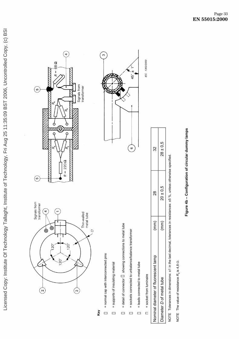
Nom
inal
dia
met
er o
f flu
ores
cent
lam
p (m
m)
28
32
Dia
met
er D
of m
etal
tube
(m
m)
20 ±
0,5
28
± 0
,5
NO
TE
Tole
ranc
es in
dim
ensi
ons:
±1
in th
e la
st d
ecim
al, t
oler
ance
s in
resi
stan
ces:
±5
%, u
nles
s ot
herw
ise
spec
ified
.
NO
TE
The
valu
e of
resi
stan
ce R
x is
4,8
Ω.
Figu
re 4
b –
Con
figur
atio
n of
circ
ular
dum
my
lam
ps
➀
= no
rmal
cap
with
inte
rcon
nect
ed p
ins
➁
= su
ppor
ts o
f ins
ulat
ing
mat
eria
l
➂
= de
tail
of c
onne
ctor
➀ s
how
ing
conn
ectio
ns to
met
al tu
be
➃
= so
cket
s co
nnec
ted
to u
nbal
ance
/bal
ance
tran
sfor
mer
➄
= le
ads
conn
ecte
d to
met
al tu
be
➅=
sock
et fr
om lu
min
aire
Key
IEC
13
63/2
000
Pa3 eg30002:51055 NE
Page 33EN 55015:2000
Lice
nsed
Cop
y: In
stitu
te O
f Tec
hnol
ogy
Tal
lagh
t, In
stitu
te o
f Tec
hnol
ogy,
Fri
Aug
25
11:3
5:09
BS
T 2
006,
Unc
ontr
olle
d C
opy,
(c)
BS
I

N
OTE
To
lera
nces
in d
imen
sion
s: ±
1 in
the
last
dec
imal
, tol
eran
ces
in re
sist
ance
s: ±
5 %
, unl
ess
othe
rwis
e sp
ecifi
ed.
Dim
ensi
ons
in m
illim
etre
s
NO
TE
L =
leng
th o
f the
real
fluo
resc
ent l
amp
min
us 4
0 m
m
Figu
re 4
c –
Dum
my
lam
p fo
r 15
mm
fluo
resc
ent l
amps
IEC
13
64/2
000
43 egaP0002:51055 NE
Page 34EN 55015:2000
Lice
nsed
Cop
y: In
stitu
te O
f Tec
hnol
ogy
Tal
lagh
t, In
stitu
te o
f Tec
hnol
ogy,
Fri
Aug
25
11:3
5:09
BS
T 2
006,
Unc
ontr
olle
d C
opy,
(c)
BS
I

N
OTE
To
lera
nces
in d
imen
sion
s: ±
1 in
the
last
dec
imal
, tol
eran
ces
in re
sist
ance
s: ±
5 %
, unl
ess
othe
rwis
e sp
ecifi
ed.
Dim
ensi
ons
in m
illim
etre
s
Figu
re 4
d –
Dum
my
lam
p fo
r 15
mm
sin
gle-
capp
ed fl
uore
scen
t lam
ps
IEC
13
65/2
000
53 egaP0002:51055 NE
Page 35EN 55015:2000
Lice
nsed
Cop
y: In
stitu
te O
f Tec
hnol
ogy
Tal
lagh
t, In
stitu
te o
f Tec
hnol
ogy,
Fri
Aug
25
11:3
5:09
BS
T 2
006,
Unc
ontr
olle
d C
opy,
(c)
BS
I
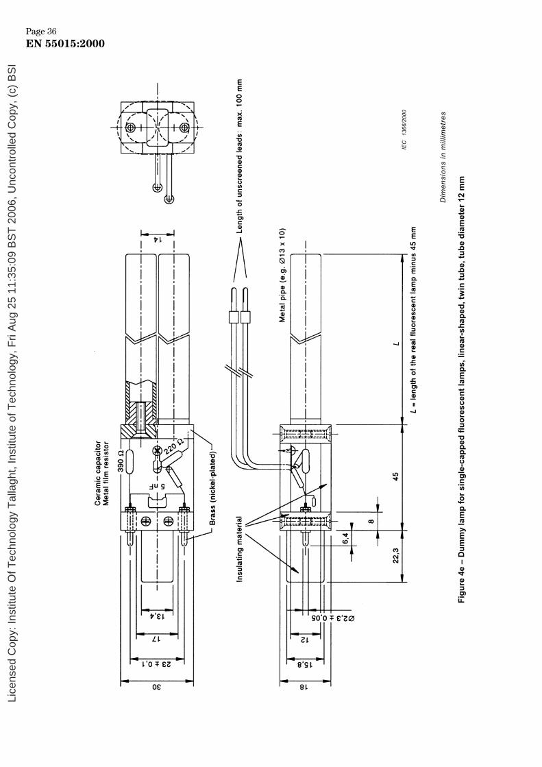
Dim
ensi
ons
in m
illim
etre
s
Figu
re 4
e –
Dum
my
lam
p fo
r sin
gle-
capp
ed fl
uore
scen
t lam
ps, l
inea
r-sh
aped
, tw
in tu
be, t
ube
diam
eter
12
mm
IEC
13
66/2
000
63 egaP0002:51055 NE
Page 36EN 55015:2000
Lice
nsed
Cop
y: In
stitu
te O
f Tec
hnol
ogy
Tal
lagh
t, In
stitu
te o
f Tec
hnol
ogy,
Fri
Aug
25
11:3
5:09
BS
T 2
006,
Unc
ontr
olle
d C
opy,
(c)
BS
I

Fi
gure
4f –
Dum
my
lam
p fo
r sin
gle-
capp
ed fl
uore
scen
t lam
ps, l
inea
r-sh
aped
, qua
d tu
be, d
iam
eter
12
mm
Dim
ensi
ons
in m
illim
etre
s
IEC
13
67/2
000
73 egaP0002:51055 NE
Page 37EN 55015:2000
Lice
nsed
Cop
y: In
stitu
te O
f Tec
hnol
ogy
Tal
lagh
t, In
stitu
te o
f Tec
hnol
ogy,
Fri
Aug
25
11:3
5:09
BS
T 2
006,
Unc
ontr
olle
d C
opy,
(c)
BS
I

!
"
Page83 0002:51055 NE
Page 38EN 55015:2000
Lice
nsed
Cop
y: In
stitu
te O
f Tec
hnol
ogy
Tal
lagh
t, In
stitu
te o
f Tec
hnol
ogy,
Fri
Aug
25
11:3
5:09
BS
T 2
006,
Unc
ontr
olle
d C
opy,
(c)
BS
I

!
"
Page93 0002:51055 NE
Page 39EN 55015:2000
Lice
nsed
Cop
y: In
stitu
te O
f Tec
hnol
ogy
Tal
lagh
t, In
stitu
te o
f Tec
hnol
ogy,
Fri
Aug
25
11:3
5:09
BS
T 2
006,
Unc
ontr
olle
d C
opy,
(c)
BS
I

NOTE Dimensions in millimetres
NOTE 1 Tolerances in dimensions: ±1 in the last decimal, unless otherwise specified.
NOTE 2 For good reference, adjust the lamp to the highest position.
NOTE 3 For good reference, the lampholder shall be of insulating material.
Figure 7 – Conical metal housing for self-ballasted fluorescent lamps
IEC 1372/2000
04 egaP0002:51055 NE
Page 40EN 55015:2000
Lice
nsed
Cop
y: In
stitu
te O
f Tec
hnol
ogy
Tal
lagh
t, In
stitu
te o
f Tec
hnol
ogy,
Fri
Aug
25
11:3
5:09
BS
T 2
006,
Unc
ontr
olle
d C
opy,
(c)
BS
I

Annex A (normative)
Electrical and constructional requirements for the low-capacitance
balance-to-unbalance transformer
A.1 General
Care is necessary in the construction of the transformer in order to meet the performance requirements.
An example of a suitable construction is shown in figures A.2a, A.2b, A.2c and A.2d, together with the materials to be used.
A.2 Basic requirements
A.2.1 The output impedance of the transformer, when the input is terminated by 50 Ω, shall be 150 Ω ± 10 % with a phase angle not exceeding 10°. The isolation of the transformer is checked as follows (see figure A.1).
Using a voltmeter with a high impedance (for example 1 MΩ), but shunted with a 150 Ω resistor, the voltage V ′2 (see figure A.1b) and V ′′2 (see figure A.1c) measured between each secondary terminal and the earth connection of the transformer, shall be at least 43 dB below the voltage V1 (see figure A.1a) measured across the secondary terminals, with constant output level from the r.f. generator.
A.2.2 The requirements of A.1 shall be met throughout the frequency range 150 kHz to 1 605 kHz.
A.2.3 The transformer shall be mounted in a metal box. The side where the output terminals are mounted is constructed of an insulating material, and the earth connection of the input terminal shall be connected to the metal box (see figure A.2d).
A.3 Additional requirements
To allow for simplified measuring procedures, the following additional requirements shall be applied.
a) In the frequency range 150 kHz to 1 605 kHz, the transformer shall have a transfer characteristic which is flat within 0,5 dB.
b) The transformer is constructed in such a way that U1, as defined in 5.4.2, can be adjusted to a value of 1 V, without causing saturation effects in the ferrite core.
Page 41EN 55010002:5
Page 41EN 55015:2000
Lice
nsed
Cop
y: In
stitu
te O
f Tec
hnol
ogy
Tal
lagh
t, In
stitu
te o
f Tec
hnol
ogy,
Fri
Aug
25
11:3
5:09
BS
T 2
006,
Unc
ontr
olle
d C
opy,
(c)
BS
I

Figure A.1a
Figure A.1b
Figure A.1c
Figure A.1 – Isolation test configuration
IEC 1373/2000
IEC 1374/2000
IEC 1375/2000
24 egaP0002:51055 NE
Page 42EN 55015:2000
Lice
nsed
Cop
y: In
stitu
te O
f Tec
hnol
ogy
Tal
lagh
t, In
stitu
te o
f Tec
hnol
ogy,
Fri
Aug
25
11:3
5:09
BS
T 2
006,
Unc
ontr
olle
d C
opy,
(c)
BS
I

Figure A.2a – Balance-to-unbalance transformer circuit
IEC 1376/2000
34 egaP0002:51055 NE
Page 43EN 55015:2000
Lice
nsed
Cop
y: In
stitu
te O
f Tec
hnol
ogy
Tal
lagh
t, In
stitu
te o
f Tec
hnol
ogy,
Fri
Aug
25
11:3
5:09
BS
T 2
006,
Unc
ontr
olle
d C
opy,
(c)
BS
I

NOTE Dimensions in millimetres
Figure A.2b – Details of transformer core construction
Figure A.2c – Details of transformer core construction
IEC 1377/2000
IEC 1378/2000
44 egaP0002:51055 NE
Page 44EN 55015:2000
Lice
nsed
Cop
y: In
stitu
te O
f Tec
hnol
ogy
Tal
lagh
t, In
stitu
te o
f Tec
hnol
ogy,
Fri
Aug
25
11:3
5:09
BS
T 2
006,
Unc
ontr
olle
d C
opy,
(c)
BS
I

NOTE Dimensions in millimetres
Figure A.2d – Construction of transformer
––––––––––––––
IEC 1379/2000
54 egaP0002:51055 NE
Page 45EN 55015:2000
Lice
nsed
Cop
y: In
stitu
te O
f Tec
hnol
ogy
Tal
lagh
t, In
stitu
te o
f Tec
hnol
ogy,
Fri
Aug
25
11:3
5:09
BS
T 2
006,
Unc
ontr
olle
d C
opy,
(c)
BS
I

Annex ZA (normative)
Normative references to international publications with their corresponding European publications
This European Standard incorporates by dated or undated reference, provisions from other publications. These normative references are cited at the appropriate places in the text and the publications are listed hereafter. For dated references, subsequent amendments to or revisions of any of these publications apply to this European Standard only when incorporated in it by amendment or revision. For undated references the latest edition of the publication referred to applies (including amendments).
NOTE When an international publication has been modified by common modifications, indicated by (mod), the relevant EN/HD applies.
Publication Year Title EN/HD Year
IEC 60050-161 1990 International Electrotechnical Vocabulary (IEV) — Chapter 161: Electromagnetic compatibility
— —
IEC 60155 1993 Glow-starters for fluorescent lamps EN 60155 1995
IEC 60598 (mod) Series Luminaires EN 60598 Series
CISPR 11 (mod) 1997 Industrial, scientific and medical (ISM) radio-frequency equipment — Radio disturbance characteristics — Limits and methods of measurement
EN 55011 1998
CISPR 16-1 1999 Specification for radio disturbance and immunity measuring apparatus and methods — Part 1: Radio disturbance and immunity measuring apparatus
!CISPR 16-2 1996 Specification for radio disturbance and immunity measuring apparatus and methods — Part 2: Methods of measurement of disturbances and immunity
— —
CISPR 22 (mod) 1997 Information technology equipment — Radio disturbance characteristics — Limits and methods of measurement
EN 55022 +corr. August
1998 1999"
Page64 0002:51055 NE
Page 46EN 55015:2000
Lice
nsed
Cop
y: In
stitu
te O
f Tec
hnol
ogy
Tal
lagh
t, In
stitu
te o
f Tec
hnol
ogy,
Fri
Aug
25
11:3
5:09
BS
T 2
006,
Unc
ontr
olle
d C
opy,
(c)
BS
I

blank
Lice
nsed
Cop
y: In
stitu
te O
f Tec
hnol
ogy
Tal
lagh
t, In
stitu
te o
f Tec
hnol
ogy,
Fri
Aug
25
11:3
5:09
BS
T 2
006,
Unc
ontr
olle
d C
opy,
(c)
BS
I

BS EN 55015:2001
BSI
389 Chiswick High Road
London
W4 4AL
BSI — British Standards InstitutionBSI is the independent national body responsible for preparing British Standards. It presents the UK view on standards in Europe and at the international level. It is incorporated by Royal Charter.
Revisions
British Standards are updated by amendment or revision. Users of British Standards should make sure that they possess the latest amendments or editions.
It is the constant aim of BSI to improve the quality of our products and services. We would be grateful if anyone finding an inaccuracy or ambiguity while using this British Standard would inform the Secretary of the technical committee responsible, the identity of which can be found on the inside front cover. Tel: +44 (0)20 8996 9000. Fax: +44 (0)20 8996 7400.
BSI offers members an individual updating service called PLUS which ensures that subscribers automatically receive the latest editions of standards.
Buying standards
Orders for all BSI, international and foreign standards publications should be addressed to Customer Services. Tel: +44 (0)20 8996 9001. Fax: +44 (0)20 8996 7001. Email: [email protected]. Standards are also available from the BSI website at http://www.bsi-global.com.
In response to orders for international standards, it is BSI policy to supply the BSI implementation of those that have been published as British Standards, unless otherwise requested.
Information on standards
BSI provides a wide range of information on national, European and international standards through its Library and its Technical Help to Exporters Service. Various BSI electronic information services are also available which give details on all its products and services. Contact the Information Centre. Tel: +44 (0)20 8996 7111. Fax: +44 (0)20 8996 7048. Email: [email protected].
Subscribing members of BSI are kept up to date with standards developments and receive substantial discounts on the purchase price of standards. For details of these and other benefits contact Membership Administration. Tel: +44 (0)20 8996 7002. Fax: +44 (0)20 8996 7001. Email: [email protected].
Information regarding online access to British Standards via British Standards Online can be found at http://www.bsi-global.com/bsonline.
Further information about BSI is available on the BSI website at http://www.bsi-global.com.
Copyright
Copyright subsists in all BSI publications. BSI also holds the copyright, in the UK, of the publications of the international standardization bodies. Except as permitted under the Copyright, Designs and Patents Act 1988 no extract may be reproduced, stored in a retrieval system or transmitted in any form or by any means – electronic, photocopying, recording or otherwise – without prior written permission from BSI.
This does not preclude the free use, in the course of implementing the standard, of necessary details such as symbols, and size, type or grade designations. If these details are to be used for any other purpose than implementation then the prior written permission of BSI must be obtained.
Details and advice can be obtained from the Copyright & Licensing Manager. Tel: +44 (0)20 8996 7070. Fax: +44 (0)20 8996 7553. Email: [email protected].
Lice
nsed
Cop
y: In
stitu
te O
f Tec
hnol
ogy
Tal
lagh
t, In
stitu
te o
f Tec
hnol
ogy,
Fri
Aug
25
11:3
5:09
BS
T 2
006,
Unc
ontr
olle
d C
opy,
(c)
BS
I


![IEEE Std 421.5-1992, IEEE Recommended Practice for Excitation …u.dianyuan.com/bbs/u/38/1139052706.pdf · 2020. 5. 12. · [2] IEEE Std 100-1988, IEEE Standard Dictionary of Electrical](https://static.fdocuments.in/doc/165x107/611c6fe7b258d970e2075190/ieee-std-4215-1992-ieee-recommended-practice-for-excitation-u-2020-5-12.jpg)