Limitations - MrMoo CRH split up/03 Limitations.pdf · Limitations Limitations Table of Contents...
48
King Air 200 Developed for Training Purposes 3-1 October 1996 Limitations Limitations Table of Contents General Limitations . . . . . . . . . . . . . . . . . . . . . 3-4 Airstair Door . . . . . . . . . . . . . . . . . . . . . . . . . 3-4 Authorized Operations . . . . . . . . . . . . . . . . . . . . 3-4 Baggage Limits . . . . . . . . . . . . . . . . . . . . . . . . 3-5 Maximum Weight in Baggage Compartment . . . . . . . . 3-5 Certification Status . . . . . . . . . . . . . . . . . . . . . . 3-5 Cargo . . . . . . . . . . . . . . . . . . . . . . . . . . . . . 3-5 Cargo Door . . . . . . . . . . . . . . . . . . . . . . . . . . 3-6 Emergency Exit . . . . . . . . . . . . . . . . . . . . . . . . 3-6 Occupancy Limits . . . . . . . . . . . . . . . . . . . . . . 3-6 Passenger Seating . . . . . . . . . . . . . . . . . . . . . . 3-7 Couch/Passenger Seats . . . . . . . . . . . . . . . . . 3-7 Aft-Facing Seats . . . . . . . . . . . . . . . . . . . . . . 3-7 Lateral-Tracking Seats . . . . . . . . . . . . . . . . . . 3-7 Passenger Shoulder Harness . . . . . . . . . . . . . . 3-7 Maneuvers . . . . . . . . . . . . . . . . . . . . . . . . . . 3-7 Minimum Flight Crew . . . . . . . . . . . . . . . . . . . . . 3-7 Structural Limitations . . . . . . . . . . . . . . . . . . . . . 3-8 King Air 200 . . . . . . . . . . . . . . . . . . . . . . . . 3-8 King Air B200 . . . . . . . . . . . . . . . . . . . . . . . 3-9
-
Upload
truongkien -
Category
Documents
-
view
232 -
download
1
Transcript of Limitations - MrMoo CRH split up/03 Limitations.pdf · Limitations Limitations Table of Contents...
King Air 200 Developed for Training Purposes 3-1October 1996
Limitations
LimitationsTable of ContentsGeneral Limitations . . . . . . . . . . . . . . . . . . . . . 3-4
Airstair Door . . . . . . . . . . . . . . . . . . . . . . . . . 3-4
Authorized Operations . . . . . . . . . . . . . . . . . . . . 3-4
Baggage Limits . . . . . . . . . . . . . . . . . . . . . . . . 3-5
Maximum Weight in Baggage Compartment . . . . . . . . 3-5
Certification Status . . . . . . . . . . . . . . . . . . . . . . 3-5
Cargo . . . . . . . . . . . . . . . . . . . . . . . . . . . . . 3-5
Cargo Door . . . . . . . . . . . . . . . . . . . . . . . . . . 3-6
Emergency Exit . . . . . . . . . . . . . . . . . . . . . . . . 3-6
Occupancy Limits . . . . . . . . . . . . . . . . . . . . . . 3-6
Passenger Seating . . . . . . . . . . . . . . . . . . . . . . 3-7
Couch/Passenger Seats . . . . . . . . . . . . . . . . . 3-7
Aft-Facing Seats . . . . . . . . . . . . . . . . . . . . . . 3-7
Lateral-Tracking Seats . . . . . . . . . . . . . . . . . . 3-7
Passenger Shoulder Harness . . . . . . . . . . . . . . 3-7
Maneuvers . . . . . . . . . . . . . . . . . . . . . . . . . . 3-7
Minimum Flight Crew . . . . . . . . . . . . . . . . . . . . . 3-7
Structural Limitations . . . . . . . . . . . . . . . . . . . . . 3-8
King Air 200 . . . . . . . . . . . . . . . . . . . . . . . . 3-8
King Air B200 . . . . . . . . . . . . . . . . . . . . . . . 3-9

3-2 Developed for Training Purposes King Air 200October 1996
CAE SimuFlite
Windows and Windshield . . . . . . . . . . . . . . . . . . 3-10
Fuselage Side Window . . . . . . . . . . . . . . . . . . . 3-10
Windshield . . . . . . . . . . . . . . . . . . . . . . . . . . 3-11
Operational Limits . . . . . . . . . . . . . . . . . . . . . 3-13
Maximum Operating Pressure Altitude . . . . . . . . . . 3-13
Cabin Pressurization Limit . . . . . . . . . . . . . . . . . 3-13
Cabin Pressurization Controller . . . . . . . . . . . . . . 3-14
Crosswind/Tailwind Components . . . . . . . . . . . . . 3-14
External Power Unit . . . . . . . . . . . . . . . . . . . . . 3-14
Generator Limits . . . . . . . . . . . . . . . . . . . . . . 3-14
Starter Limitations . . . . . . . . . . . . . . . . . . . . . . 3-17
300-Amp Lear-Siegler . . . . . . . . . . . . . . . . . . . 3-17
OAT Limits . . . . . . . . . . . . . . . . . . . . . . . . . . 3-17
Airspeed Limitations . . . . . . . . . . . . . . . . . . . . 3-18
Static Wicks (King Air 200) . . . . . . . . . . . . . . . . . 3-22
Weight Limitations . . . . . . . . . . . . . . . . . . . . 3-23
Center of Gravity Limits . . . . . . . . . . . . . . . . . . 3-23
Flight Load Factor Limits . . . . . . . . . . . . . . . . . . 3-23
Mean Aerodynamic Chord . . . . . . . . . . . . . . . . . 3-23

Systems Limitations . . . . . . . . . . . . . . . . . . . 3-25
Autopilot – King Air 200 . . . . . . . . . . . . . . . . . . 3-25
Fuel System . . . . . . . . . . . . . . . . . . . . . . . . . 3-25
Ice and Rain Protection Systems . . . . . . . . . . . . . 3-29
Instrument Markings . . . . . . . . . . . . . . . . . . . . 3-31
Landing Gear Cycle Limits (Hydraulic) . . . . . . . . . . 3-31
Powerplant . . . . . . . . . . . . . . . . . . . . . . . . . . 3-32
Propellers . . . . . . . . . . . . . . . . . . . . . . . . . . 3-45
Limitations
King Air 200 Developed for Training Purposes 3-3September 2002

CAE SimuFlite
3-4 Developed for Training Purposes King Air 200June 2000
General LimitationsAirstair Door■ Do not open or check security by moving door handle while
aircraft is pressurized and/or in flight.
Handle is in locked position when arm is around plunger.
■ See AFM Supplements section for limitations with the airstairdoor removed.
Authorized Operations■ Day and Night VFR
■ Day and Night IFR
■ Known icing conditions
■ FAR Part 91 operations when all pertinent information andperformance considerations are complied with.
■ FAR Part 135 operations when all pertinent information andperformance considerations are complied with.
WARNING: Only one person should be on the airstair doorstairway at any one time.
NOTE: No aircraft is certified for known severe icing.
WARNING: Only a crew member should operate the door.

Limitations
King Air 200 Developed for Training Purposes 3-5October 1996
Baggage LimitsMaximum Weight in Baggage Compartment
Prior to BB-1052, BB-1091, and BL-58:
With Fold-up Seats . . . . . . . . . . . . . . . . 370 LBS
Without Fold-up Seats . . . . . . . . . . . . . . 410 LBS
BB-1052, BB-1091 and subsequent; BL-58 and subsequent;prior aircraft with Beech Kit #101-5068-1 installed:
With Fold-up Seats . . . . . . . . . . . . . . . . 510 LBS
Without Fold-up Seats . . . . . . . . . . . . . . 550 LBS
Certification Status■ Normal Category, FAR Part 23
Cargo■ All cargo shall be properly secured by an FAA-approved
cargo restraint system.
■ Cargo must be arranged to permit free access to all exits andemergency exits.
WARNING: Do not carry children in the baggage compartment unless secured in a seat.
WARNING: Unless authorized by applicable Departmentof Transportation regulations, do not carry hazardousmaterial anywhere in the aircraft.

CAE SimuFlite
3-6 Developed for Training Purposes King Air 200June 2000
Cargo Door■ 200C/B200C - Do not open or check security by moving door
handle while aircraft is pressurized and/or in flight.
■ The cabin flooring section withstands loads of 200 poundsper square foot supported on the seat tracks. Floor areaswhere seat tracks are not present (walkways and aft bag-gage/utility area) supports 100 pounds per square foot loads.
Emergency Exit■ Emergency exit must be unlocked before takeoff.
Occupancy LimitsFAR Part 91 Operations (maximum, including crew) . . . . 15
FAR Part 135 Operations(maximum) . . . . . . . . . . . . . . 9 Passengers Plus Crew
WARNING: Only a crew member should operate thedoor.
NOTE: Prior to first flight on the day, check cabindoor/cargo door annunciator circuitry in accordancewith Cabin/Cargo Door Annunciator Check in the AFM.

Passenger SeatingCouch/Passenger Seats■ Do not occupy couch as chaise lounge during takeoff and
landing.
■ Maximum weight of drawer contents is 30 lbs per drawer.
■ The headrest should be positioned properly for the occupant.
Aft-Facing Seats■ Only aft-facing seats (placarded as such on the leg cross-
member) are authorized in the aft-facing position.
■ The seatback of each occupied aft-facing seat must be in thefully raised position and the headrest in the full-up positionfor takeoff and landing.
Lateral-Tracking Seats (if installed)■ Seat must be in outboard position for takeoff and landing.
Passenger Shoulder Harness■ Shoulder harness must be worn during takeoff and landing
with seat in outboard position, seat back upright, and head-rest fully extended.
Maneuvers■ The Beechcraft Super King Air B200 and B200C are Normal
Category Airplanes. Acrobatic maneuvers, including spins,are prohibited.
Minimum Flight Crew■ One pilot.
Limitations
King Air 200 Developed for Training Purposes 3-7October 1996
CAE SimuFlite
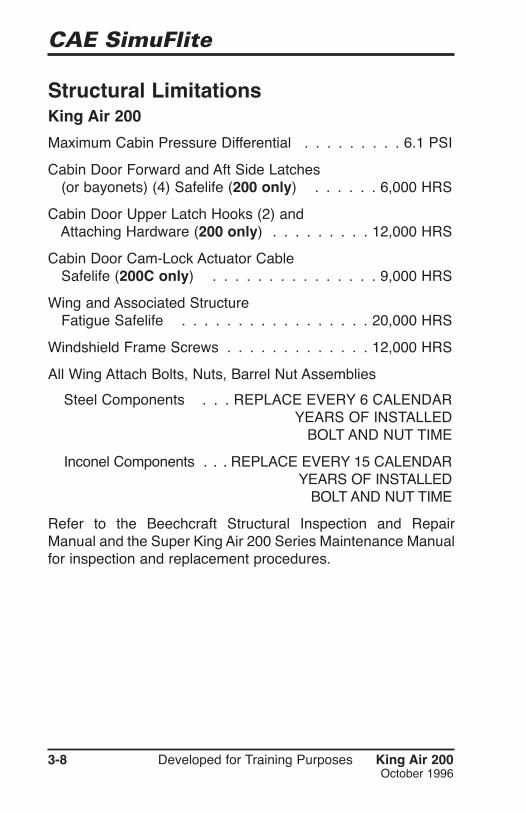
Structural LimitationsKing Air 200
Maximum Cabin Pressure Differential . . . . . . . . . 6.1 PSI
Cabin Door Forward and Aft Side Latches(or bayonets) (4) Safelife (200 only) . . . . . . 6,000 HRS
Cabin Door Upper Latch Hooks (2) andAttaching Hardware (200 only) . . . . . . . . . 12,000 HRS
Cabin Door Cam-Lock Actuator CableSafelife (200C only) . . . . . . . . . . . . . . . 9,000 HRS
Wing and Associated Structure Fatigue Safelife . . . . . . . . . . . . . . . . . 20,000 HRS
Windshield Frame Screws . . . . . . . . . . . . . 12,000 HRS
All Wing Attach Bolts, Nuts, Barrel Nut Assemblies
Steel Components . . . REPLACE EVERY 6 CALENDAR . . . . . . . . . . . . . . . . . . . .YEARS OF INSTALLED . . . . . . . . . . . . . . . . . . . . .BOLT AND NUT TIME
Inconel Components . . . REPLACE EVERY 15 CALENDAR . . . . . . . . . . . . . . . . . . . . .YEARS OF INSTALLED . . . . . . . . . . . . . . . . . . . . . .BOLT AND NUT TIME
Refer to the Beechcraft Structural Inspection and RepairManual and the Super King Air 200 Series Maintenance Manualfor inspection and replacement procedures.
3-8 Developed for Training Purposes King Air 200October 1996

Limitations
King Air 200 Developed for Training Purposes 3-9October 1996
King Air B200S/Ns Prior to BB-1193 and BL-73 except BB-1158 and BB-1167
Cabin and Door Forward and Aft Side Latches(or bayonets) (4) Safelife (B200 only) . . . . . . 6,000 HRS
Cabin Door Upper Latch Hooks (2) andAttaching Hardware (B200 only) . . . . . . . . 12,000 HRS
Cabin Door Cam-Lock Actuator CableSafelife (B200C only) . . . . . . . . . . . . . . . 9,000 HRS
Wing and Associated Structure Fatigue Safelife . . . . . . . . . . . . . . . . . 15,000 HRS
Windshield Frame Screws . . . . . . . . . . . . . 12,000 HRS
All Wing Attach Bolts, Nuts, Barrel Nut Assemblies:
Steel Components . . . REPLACE EVERY 6 CALENDAR . . . . . . . . . . . . . . . . . . . .YEARS OF INSTALLED . . . . . . . . . . . . . . . . . . . . .BOLT AND NUT TIME
Inconel Components . . . REPLACE EVERY 15 CALENDAR . . . . . . . . . . . . . . . . . . . . .YEARS OF INSTALLED . . . . . . . . . . . . . . . . . . . . . .BOLT AND NUT TIME
Refer to the Beechcraft Structural Inspection and RepairManual and the Super King Air 200 Series Maintenance Manualfor inspection and replacement procedures.
BB-1158, BB-1167; BB-1193 and subsequent; BL-73 andsubsequent
Refer to Chapter 4 of the Super King Air 200 Series MaintenanceManual for structural limitations.

CAE SimuFlite
Windows and WindshieldKing Air 200/King Air B200 prior to BB-1193 and BL-73except BB-1158 and 1167
Fuselage Side Window■ If cracking, chipping, or stress crazing that can be felt with a
fingernail occurs in either ply of the exterior window, replacethe window according to instructions in the MaintenanceManual.
■ If the window cannot be replaced prior to the next flight, pressurized flight is prohibited. Install the following placardsto conduct unpressurized flight.
– Install the following placard in clear view of the pilot:
PRESSURIZED FLIGHT IS PROHIBITED DUE TO ADAMAGED WINDOW. CONDUCT FLIGHT WITH THECABIN PRESS SWITCH IN THE DUMP POSITION.
– Install the following placard next to the pressurization control:
UNPRESSURIZED FLIGHT ONLY PERMITTED.
■ If a crack exists in both the inner and outer plies of the exterior window, replace the window prior to further flightunless an appropriate “Ferry Permit” is obtained through theproper authority.
3-10 Developed for Training Purposes King Air 200October 1996

Limitations
King Air 200 Developed for Training Purposes 3-11March 1997
Crack in Side Window or WindshieldIf it has been determined that a crack has developed in any sidewindow or windshield:
■ Maintain altitude at 25,000 ft or less.
■ Reset pressurization controller to maintain 4.0 psi or less asrequired.
NOTE: Visibility throught the windshield may be slightlyimpaired. Windshield wipers may be damaged if usedon a cracked surface. Heating elements may be inoper-ative in the area of the crack.
CAUTION: Prior to next flight, maintenance actions arerequired. Refer to the AIrworthiness Limitations inChapter 4 of the Super King Air 200 Series MaintenanceManual.

3-12 Developed for Training Purposes King Air 200October 1996
CAE SimuFlite

Limitations
King Air 200 Developed for Training Purposes 3-13September 2002
Operational LimitsMaximum Operating Pressure AltitudeNormal Operations – King Air 200 Prior to BB-54,
except 38, 39, 44 . . . . . . . . . . . . . . . . . 31,000 FT
Normal Operations – King Air 200 BB-38, 42, 44, 54 and subsequent*; BL-1 and subsequent . 35,000 FT
*Also includes earlier aircraft with Beech kit Nos. 101-5007-1 and 101-5008-1 in compliance with Beechcraft ServiceInstruction No. 0776-341.
Normal Operations – King Air B200 . . . . . . . 35,000 FT
King Air 200 with Aviation Gasoline:
Both Standby Boost Pumps Operative . . . . . . 31,000 FT
Either Standby Boost Pump Inoperative . . . . . 20,000 FT
Climbs without Crossfeed Capability . . . . . . . 20,000 FT
Yaw Damper System Inoperative . . . . . . . . . 17,000 FT
No restriction with Raisbeck AFT strakes installed.
VMCA Demonstration Minimum . . . . . . . . 5,000 FT AGL
Cabin Pressurization LimitKing Air 200 – Maximum CabinPressure Differential . . . . . . . . . . . . . . . . . . . 6.1 PSI
King Air B200 – Maximum CabinPressure Differential . . . . . . . . . . . . . . . . . . . 6.6 PSI
CAE SimuFlite
3-14 Developed for Training Purposes King Air 200September 2002
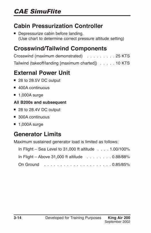
Cabin Pressurization Controller■ Depressurize cabin before landing.
(Use chart to determine correct pressure altitude setting)
Crosswind/Tailwind ComponentsCrosswind (maximum demonstrated) . . . . . . . . . 25 KTS
Tailwind (takeoff/landing [maximum charted]) . . . . . 10 KTS
External Power Unit■ 28 to 28.5V DC output
■ 400A continuous
■ 1,000A surge
All B200s and subsequent
■ 28 to 28.4V DC output
■ 300A continuous
■ 1,000A surge
Generator LimitsMaximum sustained generator load is limited as follows:
In Flight – Sea Level to 31,000 ft altitude . . . . 1.00/100%
In Flight – Above 31,000 ft altitude . . . . . . . . 0.88/88%
On Ground . . . . . . . . . . . . . . . . . . . . . 0.85/85%

Limitations
King Air 200 Developed for Training Purposes 3-15September 2002
Minimum Gas Generator RPM – N1%
Without A/C With A/C(right engine only)
Generator Load
King Air 2000 to 0.70 52 600.70 to .75 55 600.75 to 0.80 60 600.80 to 0.85 65 65
King Air B2000 to 0.75 56 620.75 to 0.80 60 620.80 to 0.85 65 65
BB1439 and sub0 to 0.75 61 620.75 to 0.80 61 620.80 to 0.85 65 65
Table 3-A; King Air 200 and B200 Generator Limits
Table 3-B; 300A Lear-Siegler Starter-Generator 23085-001Limits
Without A/C With A/C (rightengine only)
If Flight(all altitudes)
Minimum Gas Generator RPM – N1%
Generator Load
0 to 0.75 IDLE 62 IDLE
0.75 to 1.00 63 68 85
■ During ground operation, observe the limitations shown inTables 3-A, 3-B, and 3-C (following page).
CAE SimuFlite
3-16 Developed for Training Purposes King Air 200October 1996
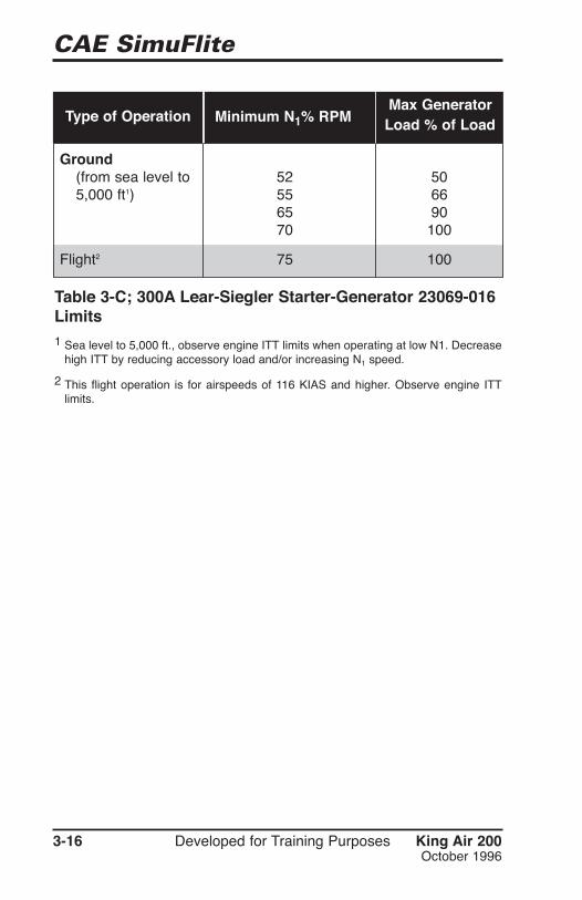
Minimum N1% RPMMax GeneratorLoad % of LoadType of Operation
Ground(from sea level to 52 505,000 ft1) 55 66
65 9070 100
Flight2 75 100
Table 3-C; 300A Lear-Siegler Starter-Generator 23069-016Limits1 Sea level to 5,000 ft., observe engine ITT limits when operating at low N1. Decrease
high ITT by reducing accessory load and/or increasing N1 speed.
2 This flight operation is for airspeeds of 116 KIAS and higher. Observe engine ITTlimits.

Limitations
King Air 200 Developed for Training Purposes 3-17October 1996
Starter Limitations■ Standard Start Cycle:
– 40 seconds ON/60 seconds OFF
– 40 seconds ON/60 seconds OFF
– 40 seconds ON then 30 minutes OFF
300-Amp Lear-Siegler (Optional)
■ Standard Start Cycle:
– 30 seconds ON/3 minutes OFF
– 30 seconds ON/30 minutes OFF
■ For engine wash:
– 30 seconds ON/15 minutes OFF
■ For engine soak:
– 30 seconds ON/10 minutes OFF
– 30 seconds ON/10 minutes OFF
– 30 seconds ON/30 minutes OFF
OAT LimitsSea Level to 25,000 ft Pressure Altitude . . . MAX ISA +37°C
Above 25,000 ft Pressure Altitude . . . . . . MAX ISA + 31°C
All Altitudes . . . . . . . . . . . . . . . . . . . . . MIN -53.9°C
CAE SimuFlite
3-18 Developed for Training Purposes King Air 200October 1996
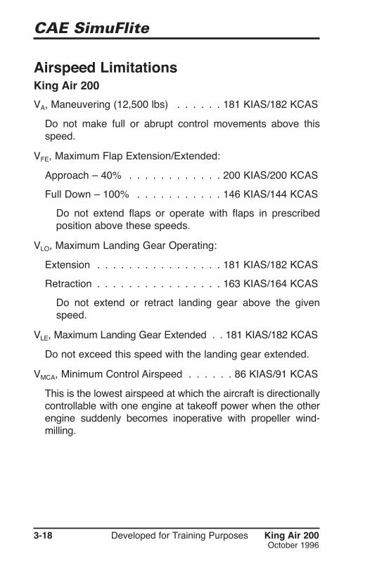
Airspeed LimitationsKing Air 200
VA, Maneuvering (12,500 lbs) . . . . . . 181 KIAS/182 KCAS
Do not make full or abrupt control movements above thisspeed.
VFE, Maximum Flap Extension/Extended:
Approach – 40% . . . . . . . . . . . . 200 KIAS/200 KCAS
Full Down – 100% . . . . . . . . . . . 146 KIAS/144 KCAS
Do not extend flaps or operate with flaps in prescribedposition above these speeds.
VLO, Maximum Landing Gear Operating:
Extension . . . . . . . . . . . . . . . . 181 KIAS/182 KCAS
Retraction . . . . . . . . . . . . . . . . 163 KIAS/164 KCAS
Do not extend or retract landing gear above the givenspeed.
VLE, Maximum Landing Gear Extended . . 181 KIAS/182 KCAS
Do not exceed this speed with the landing gear extended.
VMCA, Minimum Control Airspeed . . . . . . 86 KIAS/91 KCAS
This is the lowest airspeed at which the aircraft is directionallycontrollable with one engine at takeoff power when the otherengine suddenly becomes inoperative with propeller wind-milling.
Limitations
King Air 200 Developed for Training Purposes 3-19September 2002
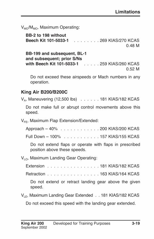
VMO/MMO, Maximum Operating:
BB-2 to 198 withoutBeech Kit 101-5033-1 . . . . . . . . 269 KIAS/270 KCAS . . . . . . . . . . . . . . . . . . . . . . . . . . . . . .0.48 M
BB-199 and subsequent, BL-1and subsequent; prior S/Nswith Beech Kit 101-5033-1 . . . . . 259 KIAS/260 KCAS . . . . . . . . . . . . . . . . . . . . . . . . . . . . . .0.52 M
Do not exceed these airspeeds or Mach numbers in anyoperation.
King Air B200/B200CVA, Maneuvering (12,500 lbs) . . . . . . 181 KIAS/182 KCAS
Do not make full or abrupt control movements above thisspeed.
VFE, Maximum Flap Extension/Extended:
Approach – 40% . . . . . . . . . . . . 200 KIAS/200 KCAS
Full Down – 100% . . . . . . . . . . . 157 KIAS/155 KCAS
Do not extend flaps or operate with flaps in prescribedposition above these speeds.
VLO, Maximum Landing Gear Operating:
Extension . . . . . . . . . . . . . . . . 181 KIAS/182 KCAS
Retraction . . . . . . . . . . . . . . . . 163 KIAS/164 KCAS
Do not extend or retract landing gear above the givenspeed.
VLE, Maximum Landing Gear Extended . . 181 KIAS/182 KCAS
Do not exceed this speed with the landing gear extended.

CAE SimuFlite
3-20 Developed for Training Purposes King Air 200June 2000
VMCA, Minimum Control Airspeed
Hartzell Propellers . . . . . . . . . . . . 86 KIAS/92 KCAS
McCauley Propellers . . . . . . . . . . . 86 KIAS/91 KCAS
This is the lowest airspeed at which the aircraft is direc-tionally controllable when one engine suddenly becomesinoperative and the other engine is at takeoff power.
VMO/MMO, Maximum Operating . . . . . 259 KIAS/260 KCAS . . . . . . . . . . . . . . . . . . . . . . . . . . . . . . .0.52 M
All Models (at 12,500 lbs)VMCG, Ground Minimum Control . . . . . . . . . . . . 84 KIAS
VMCA, Air Minimum Control . . . . . . . . . . . . . . . 86 KIAS
Takeoff (Flaps 0%/Flaps 40%):
V1/VR (rotation) . . . . . . . . . . . . . . . 95 KIAS/94 KIAS
50 ft . . . . . . . . . . . . . . . . . . . 121 KIAS/106 KIAS
V2 . . . . . . . . . . . . . . . . . . . . . 121 KIAS/106 KIAS
VSSE, Intentional One-Engine Inoperative . . . . . . 104 KIAS
VY, Two-Engine Best Rate-of-Climb . . . . . . . . . 125 KIAS
VYSE, One-Engine Inoperative Best Rate-of-Climb . . 121 KIAS
VX, Two-Engine Best of Angle-of-Climb . . . . . . . 100 KIAS
NOTE: S/Ns BB-2, BB-6 thru BB-733, BB-735 thru BB-792, BB-794 thru BB-828, BB-830, etc. (200s) Airspeedindicators marked in CAS values.
NOTE: B200 Airspeed indicators marked in IAS values.

Limitations
King Air 200 Developed for Training Purposes 3-21June 2000
VXSE, One-Engine Inoperative Best Angle-of-Climb . . 115 KIAS
Maximum Glide Range . . . . . . . . . . . . . . . . 135 KIAS
Turbulent Air Penetration . . . . . . . . . . . . . . . 170 KIAS
Balked Landing . . . . . . . . . . . . . . . . . . . . 100 KIAS
Cruise Climb:
Sea Level to 10,000 ft . . . . . . . . . . . . . . . 160 KIAS
10,000 to 20,000 ft . . . . . . . . . . . . . . . . . 140 KIAS
20,000 to 25,000 ft . . . . . . . . . . . . . . . . . 130 KIAS
25,000 to 35,000 ft . . . . . . . . . . . . . . . . . 120 KIAS
Landing Approach:
Flaps 100% . . . . . . . . . . . . . . . . . . . . . 103 KIAS
Flaps 0% . . . . . . . . . . . . . . . . . . . . . . 132 KIAS
Icing Conditions (minimum) . . . . . . . . . . . . . . 140 KIAS
Effective Windshield Deicing (maximum) . . . . . . 226 KIAS
Emergency Descent . . . . . . . . . . . . . . . . . . 181 KIAS
Manual Gear Extension . . . . . . . . . . . . . . . . 130 KIAS
Stall Speeds – Power Idle, 0° Angle-of-Bank:
100% Flaps . . . . . . . . . . . . . . . . . . 75 KIAS (VSO)
40% Flaps . . . . . . . . . . . . . . . . . . . . . . 85 KIAS
0% Flaps . . . . . . . . . . . . . . . . . . . . 99 KIAS (VS1)
Airstart (minimum) . . . . . . . . . . . . . . . . . . . 140 KIAS
Autopilot Operation . . . . . . . . . . . . . . . . . . . VMO/MMO
Flight with Cabin Entrance Door Removed . . . . . 205 KIAS

3-22 Developed for Training Purposes King Air 200June 2000
CAE SimuFlite
NOTE: Exceeding the nosewheel deflection limit markingsduring towing operations damages the nose strut/linkage.Nosewheel deflection of approximately 10° or more withthe rudder gust lock installed damages the nosewheelsteering linkage.
Static Wicks (King Air 200)■ One wick may be broken or missing from:
– Each wing (includes aileron)
– Each side of horizontal or vertical stabilizer(Maximum of 3 wicks may be missing).
Towing■ Do not tow the aircraft with rudder gust lock installed.
■ Do not tow the aircraft if one or more landing gear struts aredeflated.

Limitations
King Air 200 Developed for Training Purposes 3-23June 2000
Weight LimitationsMaximum Ramp . . . . . . . . . . . . . . . . . . 12,590 LBS
Maximum Takeoff
All Except FAR Part 135 Operations . . . . . . 12,500 LBS
FAR Part 135 Operations . . . . SEE CHART (Figure 3-1)
Maximum Landing . . . . . . . . . . . . . . . . . 12,500 LBS
Maximum Zero Fuel:
King Air 200 . . . . . . . . . . . . . . . . . . . 10,400 LBS
King Air B200 . . . . . . . . . . . . . . . . . . 11,000 LBS
Center of Gravity Limits■ The reference datum is 83.5 inches forward of the center of
the front jack point.
■ Aft limit – 196.4 inches aft of datum at all weights.
■ Forward at 12,500 lbs – 185.0 inches aft of datum with straightline variation to 181.0 inches aft of datum at 11,279 lbs.
■ Forward at 11,279 lbs or less – 181.0 inches aft of datum.
Flight Load Factor LimitsFlaps Up . . . . . . . . . . . . . . . . . . . 3.17 POSITIVE Gs . . . . . . . . . . . . . . . . . . . . . . . .1.27 NEGATIVE Gs
Flaps Down . . . . . . . . . . . . . . . . . 2.00 POSITIVE Gs . . . . . . . . . . . . . . . . . . . . . . .1.27 NEGATIVE Gs;
. . . . . . . . . . . . . . . . . . . . . . . . . . . .0.0 G (B200)
Mean Aerodynamic ChordMAC Length . . . . . . . . . . . . . . . . . . . 70.41 INCHES
Leading Edge of MAC . . . 171.23 INCHES AFT OF DATUM

CAE SimuFlite
Developed for Training Purposes King Air 200October 1996
3-24
FAR, Part 135 OperationsMaximum Enroute Weight
3-1

Limitations
King Air 200 Developed for Training Purposes 3-25September 2002
Systems LimitationsAutopilot – King Air 200FAR Part 91 or FAR Part 135 Operations■ Refer to the FAA Approved Flight Manual Supplement in the
AFM Supplements Section or applicable FAR.
Fuel SystemApproved Fuel Anti-Icing Additive■ Use anti-icing additive conforming to Specification MIL-I-
27686.
Minimum Temperature LimitEngine oil is used to heat the fuel on entering the fuel control.Since no temperature measurement is available for the fuel atthis point, it must be assumed to be the same as the OAT.Operations with Commercial Grade fuels are prohibited belowthe OAT indicated below unless approved anti-icing fuel adi-tives are used. Military Grade fuels have anti-icing additivesblended in the fuel at the refinery, and no further treatment isnecessary. Operations with Military Grade fuels below the tem-peratures indicated are prohibited.
■ A minimum oil temperature of 55°C is recommended for opti-mum fuel heater operation at takeoff power.
COMMERCIAL GRADES MILITARY GRADESJet A: -40°C JP-4: -58°C
Jet A-1: -47°C JP-5: -46°C
Jet B: -50°C JP-8: -50°C

CAE SimuFlite
3-26 Developed for Training Purposes King Air 200June 2000
Fuel Biocide Additive
Fuel biocide-fungicide BIOBOR JF in concentrations of 135 PPMor 270 PPM may be used in the fuel. BIOBOR JF may be usedas the only fuel additive, or it may be used with the anti-icingadditive conforming to MIL-I-27686 specification. Used together,the additives have no detrimental effect on the fuel system components.
Refer to the King Air 200 or Super King Air 200 SeriesMaintenance Manual and to the latest Pratt and Whitney CanadaEngine Service Bulletin No. 3044 for concentrations to use andfor procedures, recommendations, and limitations pertaining tothe use of biocidal/fungicidal additives in turbine fuels.
Approved Engine FuelsCommercial Grades . . . . . . . . . . . . Jet A, Jet A-1, Jet B
Military Grades . . . . . . . . . . . . . . . . . JP-4, JP-5, JP-8
CAUTION: Anti-icing additive must be properly blendedwith the fuel to avoid deterioration of the fuel cells. Theadditive concentration by volume shall be a minimum of0.06% and a maximum of 0.15%. Approved procedure foradding anti-icing concentrate is contained in AFM SectionIV, Normal Procedures.
CAUTION: JP-4 fuel per MIL-T-5624 has anti-icing additiveper MIL-I-27686 blended at the refinery, and no furthertreatment is necessary. Some fuel suppliers blend anti-icing additive in their storage tanks. Prior to refueling,check with the fuel supplier to determine whether or not thefuel has been blended. To assure proper concentration byvolume of fuel on board, blend only enough additive for theunblended fuel.
Limitations
King Air 200 Developed for Training Purposes 3-27June 2000
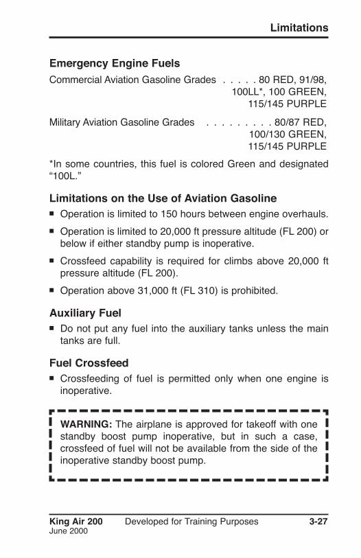
Emergency Engine FuelsCommercial Aviation Gasoline Grades . . . . . 80 RED, 91/98, . . . . . . . . . . . . . . . . . . . . . . .100LL*, 100 GREEN, . . . . . . . . . . . . . . . . . . . . . . . . .115/145 PURPLE
Military Aviation Gasoline Grades . . . . . . . . . 80/87 RED, . . . . . . . . . . . . . . . . . . . . . . . . .100/130 GREEN, . . . . . . . . . . . . . . . . . . . . . . . . .115/145 PURPLE
*In some countries, this fuel is colored Green and designated“100L.”
Limitations on the Use of Aviation Gasoline■ Operation is limited to 150 hours between engine overhauls.
■ Operation is limited to 20,000 ft pressure altitude (FL 200) orbelow if either standby pump is inoperative.
■ Crossfeed capability is required for climbs above 20,000 ftpressure altitude (FL 200).
■ Operation above 31,000 ft (FL 310) is prohibited.
Auxiliary Fuel■ Do not put any fuel into the auxiliary tanks unless the main
tanks are full.
Fuel Crossfeed■ Crossfeeding of fuel is permitted only when one engine is
inoperative.
WARNING: The airplane is approved for takeoff with onestandby boost pump inoperative, but in such a case,crossfeed of fuel will not be available from the side of theinoperative standby boost pump.

CAE SimuFlite
Fuel Gages in the Yellow Arc■ Do not take off if fuel quantity gages indicate in the yellow arc
or indicate less than 265 lbs of fuel in each main tank system.
Fuel Imbalance Between WingsMaximum Allowable . . . . . . . . . . . . . . . . . .1,000 LBS
Operating with Low Fuel Pressure■ Operation of either engine with its corresponding fuel pressure
(L/R FUEL PRESS annunciator) illuminated is limited to 10hours before overhaul or replacement of the engine-drivenfuel pump. Windmilling time need not be charged against thistime limit.
Ice and Rain Protection SystemsSustained Icing Conditions Airspeed . . . 140 KTS MINIMUM
■ On King Air B200 S/Ns BB-743, 793, 829, 854 to 870, 874to 891, 894, 896 to 911, 913 to 1438, 1440 to 1443; BL-37to 138, sustained flight in icing conditions is prohibited withflaps extended. This does not include approach and landing,if needed.
Optional Brake Deice System■ Do not operate system above 15°C ambient temperature.
■ Do not operate system longer than 10 minutes (one deicetimer cycle) with the landing gear retracted. If operation doesnot automatically terminate approximately 10 minutes aftergear retraction, manually select the system off.
■ Maintain 85% N1 or higher during periods of simultaneousbrake deice and wing boot operation. If inadequate pneu-matic pressure is developed for proper wing boot inflation,select brake deice system off.
3-28 Developed for Training Purposes King Air 200September 2002
NOTE: The rudder boost system may not operate whenthe brake deice system is in use.

Limitations
King Air 200 Developed for Training Purposes 3-29September 2002
■ Both sources of instrument bleed air must be in operation.
■ Select brake deice system off during single engine operation.
Pneumatic Deice BootsMinimum Ambient Temperature for Operationof Deicing Boots . . . . . . . . . . . . . . . . . . . . . . -40°C
Ice Vanes (Inertial Separator System)■ The ice vanes shall be extended for operations in ambient
temperature of +5°C or below when flight free of visible mois-ture cannot be assured.
■ The ice vanes shall be retracted for operations in ambienttemperatures of +15°C or above.
■ On King Air B200 aircraft, ICE VANES LEFT and RIGHTshall be extended or ENGINE ANTI-ICE LEFT and RIGHTshall be ON for operation in ambient temperatures of +5°C orbelow when flight free of visible moisture cannot be assured.
■ On King Air B200 aircraft, ICE VANES LEFT and RIGHTshall be retracted or ENGINE ANTI-ICE LEFT and RIGHTshall be OFF for all takeoff and flight operations in ambienttemperatures of above +15°C.
■ On King Air 200/B200 S/Ns prior to BB-1439; prior to BL-138, once the manual override system is activated (i.e.,anytime the ICE VANE EMERGENCY MANUAL EXTENSIONhandle has been pulled out), do not attempt to operate the icevanes electrically until the override assembly inside theengine cowling has been properly reset on the ground. Evenafter the manual extension handle has been pushed back in,the manual override system is still engaged.
■ Ice vanes should be extended for all ground operations for allB200 models. It is also recommended for all 200s.

3-30 Developed for Training Purposes King Air 200September 2002
CAE SimuFlite
Instrument MarkingsFuel Quantity
Yellow Arc (No Takeoff Range) . . . . . . . . . 0 TO 265 LBS
Cabin Pressure Differential GageKing Air 200 – before BB-195Green Arc (approved operating range) . . . . . 0 TO 6.0 PSI
Red Arc (unapproved operating range) . . . 6.0 PSI TO END . . . . . . . . . . . . . . . . . . . . . . . . . . . . .OF SCALE
King Air 200 – BB-195 and subsequent; BL-1 and subsequent
Green Arc (approved operating range) . . . . . 0 TO 6.1 PSI
Red Arc (unapproved operating range) . . . 6.1 PSI TO END . . . . . . . . . . . . . . . . . . . . . . . . . . . . .OF SCALE
King Air B200Green Arc (approved operating range) . . . . . 0 TO 6.6 PSI
Red Arc (unapproved operating range) . . . 6.6 PSI TO END . . . . . . . . . . . . . . . . . . . . . . . . . . . . .OF SCALE
Pneumatic GageGreen Arc (normal operating range) . . . . . . 12 TO 20 PSI
Red Line (maximum operating limit) . . . . . . . . . . 20 PSI
Vacuum/Gyro Suction GageKing Air 200Narrow Green Arc(normal from 35,000 to 15,000 ft MSL) . . . 3.0 TO 4.3 IN HG
Wide Green Arc(normal from 15,000 ft to sea level) . . . . 4.3 TO 5.9 IN HG
King Air 200 (alternate gage) and King Air B200Narrow Green Arc(normal from 35,000 to 15,000 ft MSL) . . . 2.8 TO 4.3 IN HG

Wide Green Arc(normal from 15,000 ft to sea level) . . . . 4.3 TO 5.9 IN HG
35K Marked on Face of Gage at . . . . . . . . . . 3.0 IN HG
15K Marked on Face of Gage at . . . . . . . . . . 4.3 IN HG
Propeller Deice AmmeterGreen Arc (normal operating range) . . 14 TO 18 AMPERES
. . . . . . . . . .18 TO 24 AMPERES (BB-1444 AND SUB)
Landing Gear Cycle Limits (Hydraulic)■ Landing gear cycles (1 up – 1 down) are limited to one every
5 minutes for a total of 6 cycles followed by a 15 minute cool-down period.
Powerplant■ Number of Engines – 2
■ Engine Manufacturer – Pratt & Whitney of Canada (Longueuil,Quebec, Canada)
■ Engine Model Number PT6A-41 (King Air 200) or PT6A-42(King Air B200)
■ Do not lift power levers in flight.
Engine Operating Limits■ The following limitations presented in Figures 3-2, 3-3 and
Tables 3D, 3E, and 3F shall be observed. Each column pre-sents limitations. The limits represented do not necessarilyoccur simultaneously. Refer to Pratt & Whitney EngineMaintenance Manual for specific actions required if limits areexceeded.
Oil Specifications■ Any oil specified by brand name in the latest revision of Pratt
& Whitney SB 3001 is approved for use in the PT6A-41(King Air 200) or the PT6A-42 (King Air B200) engine.
Limitations
King Air 200 Developed for Training Purposes 3-31September 2002

CAE SimuFlite
3-32 Developed for Training Purposes King Air 200September 2002
Overtemperature Limits – Starting Conditions Only(PT6A-41 and -42)
Adjustments:AREA A 1. Determine and correct cause of overtemperature.
2. Visually inspect through exhaust duct.3. Record in engine log book.
AREA B Perform hot section inspection.
AREA C Return engine to overhaul.
NOTE: Interturbine temperatures shown make no allowancefor instrument errors.
3-2

Limitations
King Air 200 Developed for Training PurposesSeptember 2002
3-33
Overtorque Limits – All Conditions(PT6A-40, -41, -42 and -42A)
Adjustments:AREA A No action required.
AREA B 1. Determine and correct cause of overtorque.2. Record in engine log book.
AREA C Return engine to overhaul.
3-3

3-34 Developed for Training Purposes King Air 200September 2002
CAE SimuFlite

King Air 200 Developed for Training PurposesSeptember 2002
3-35
Prop RPMN2
Oil Press
(PSI)2Oil Temp °CN1 %
Limitations
Table 3-D; King Air 200 Engine Operating Limits (PT6A-41)
1 Torque limit applies within range of 1,600 to 2,000 propeller RPM (N2). Below 1,600 RPM, torque limited to 1,100 ft-lbs.
2 When gas generator speeds are above 27,000 RPM (72% N1) and oil temperatures are between 60 and 71°C, normaloil pressure are:
100 to 135 PSI below 21,000 ft and 85 to 135 PSI at 21,000 ft and above
During extremely cold starts, oil pressure may reach 200 PSI. Oil pressure between 60 and 85 PSI is undesirable;it should be tolerated only for the completion of the fight, and then only at a reduced power setting not exceeding1,100 ft-lbs torque. Oil pressure below 60 PSI is unsafe; it requires that either the engine be shut down, or that alanding be made as soon as possible with minimum power to sustain flight. Fluctuations of ±10 PSI are acceptable.
3 These values are time limited to 5 seconds.
4 High ITT at ground idle may be corrected by reducing accessory load and/or increasing N1 RPM.
5 At approximately 70% N1.
6 Cruise torque values vary with altitude and temperature.
7 This operation is time limited to one minute.
8 These values are time limited to 10 seconds.
9 These values are time limited to 5 minutes.
Operating Condition SHP Torque(ft-lbs)1
MaxObservedITT (°C)
N1 RPM
Starting – – 10003 – – – – -40 (min)
Low Idle – - 6604 19,500 52 (min) – 60 (min) -40 to 99
High Idle – – – – 5 – – -40 to 99
Takeoff9 850 2230 750 38,100 101.5 2000 105 to 135 10 to 99
Max Continuous and 850 22306
750 38,100 101.5 2000 105 to 135 10 to 99Cruise
Cruise Climb and 850 22306
725 38,100 101.5 2000 105 to 135 0 to 99Rec Cruise
Max Reverse7 – – 750 – 88 1900 105 to 135 0 to 99
Transient – 27503 850 38,5008 102.68 22003 – 0 to 1049

3-36 Developed for Training Purposes King Air 200September 2002
CAE SimuFlite

King Air 200 Developed for Training PurposesSeptember 2002
3-37
Limitations
Table 3-E; King Air B200 Engine Operating Limits (PT6A-42); S/Ns BB-743, 793, 829, 854 to 870,874 to 891, 894, 896 to 911, 913 to 1438, 1440 to 1443; BL-37 to 1381 Torque limit applies within range of 1,600 to 2,000 propeller RPM (N2). Below 1,600 RPM, torque limited to 1,100 ft-lbs.
2 When gas generator speeds are above 27,000 RPM (72% N1) and oil temperatures are between 60 and 71°C, normal oil pressure are:
100 to 135 PSI below 21,000 ft and 85 to 135 PSI at 21,000 ft and above
During extremely cold starts, oil pressure may reach 200 PSI. Oil pressure between 60 and 85 PSI is undesirable; it should be toleratedonly for the completion of the fight, and then only at a reduced power setting not exceeding 1100 ft-lbs torque. Oil pressure below 60 PSIis unsafe; it requires that either the engine be shut down, or that a landing be made at the nearest suitable airport with minimum power tosustain flight. Fluctuations of ±10 PSI are acceptable.
3 A minimum oil temperature of 55°C is recommended for fuel heater operation at takeoff power.
4 Oil temperature limits are -40°C and 99°C. However, temperature of up to 104°C are permitted for a maximum time of 10 minutes.
5 These values are time limited to 5 seconds.
6 High ITT at ground idle may be corrected by reducing accessory load or increasing N1 RPM.
7 At approximately 70% N1.
8 Cruise torque values vary with altitude and temperature.
9 This operation is time limited to one minute.
10 These values are time limited to 10 seconds.
11 Values above 99°C are time limited to 10 minutes.
Operating Condition SHP Torque(ft-lbs)1
MaxObservedITT (°C)
N1 RPM Prop RPMN2
Oil Press
(PSI)2Oil Temp
°C3,4N1 %
Starting – – 10005 – – – – -40 (min)
Low Idle – - 7506 21,000 56 (min) – 60 (min) -40 to 99
High Idle – – – – 70 (approx.) – – -40 to 99
Takeoff 850 2230 800 38,100 101.5 2000 100 to 135 0 to 99
Max Continuous and 850 22308
800 38,100 101.5 2000 100 to 135 0 to 99Cruise
Cruise Climb and 850 22308
770 38,100 101.5 2000 100 to 135 0 to 99Rec Cruise
Max Reverse9 – – 750 – 88 1900 100 to 135 0 to 99
Transient – 27505 850 38,50010 102.610 22005 – 0 to 10411

3-38 Developed for Training Purposes King Air 200September 2002
CAE SimuFlite

King Air 200 Developed for Training PurposesSeptember 2002
Limitations
3-39
Table 3-F; King Air B200 Engine Operating Limits (PT6A-42); S/Ns BB-1439, BB-1444 and subsequentexcept BB-1463; BL-139 and subsequent; BW-1 and subsequent1 Torque limit applies within range of 1,600 to 2,000 propeller RPM (N2). Below 1,600 RPM, torque limited to 1,100 ft-lbs.2 When gas generator speeds are above 27,000 RPM (72% N1) and oil temperatures are between 60 and 71°C, normal oil pressure are:
Below 21,000 ft 100 to 135 PSI; 21,000 ft and above 85 to 135 PSIDuring extremely cold starts, oil pressure may reach 200 PSI. Oil pressure between 60 and 85 PSI is undesirable; it should be tolerated only for the com-pletion of the fight, and then only at a reduced power setting not exceeding 1100 ft-lbs torque. Oil pressure below 60 PSI is unsafe; it requires that eitherthe engine be shut down, or that a landing be made at the nearest suitable airport with minimum power to sustain flight. Fluctuations of ±10 PSI areacceptable.
3 A minimum oil temperature of 55°C is recommended for fuel heater operation at takeoff power.4 Oil temperature limits are -40°C and 99°C. However, temperature of up to 104°C are permitted for a maximum time of 10 minutes.5 These values are time limited to 5 seconds.6 High ITT at ground idle may be corrected by reducing accessory load or increasing N1 RPM.7 At approximately 70% N1.8 Cruise torque values vary with altitude and temperature.9 This operation is time limited to one minute.10 These values are time limited to 10 seconds.11 Values above 99°C are time limited to 5 minutes.12 1,100 RPM for McCauley propeller and 1,180 RPM for Hartzell propeller.
Operating Condition SHP Torque(ft-lbs)1
MaxObservedITT (°C)
N1 RPM Prop RPMN2
Oil Press
(PSI)2
Oil Temp°C3,4N1 %
Starting – – 10005 – – – – -40 (min)
Low Idle – – 7506 22,875 61 (min) 12 60 (min) -40 to 99
High Idle – – – – 7 – – -40 to 99
Takeoff6 850 2230 800 38,100 101.5 2000 100 to 135 0 to 99
Max Continuous and 850 22308
770 38,100 101.5 2000 100 to 135 0 to 99Cruise
Cruise Climb and 850 22308
770 38,100 101.5 2000 100 to 135 0 to 99Rec Cruise
Max Reverse9 – – 750 – 88 1900 100 to 135 0 to 99
Transient – 27505 850 38,50010 102.610 22005 200 0 to 10411

3-40 Developed for Training Purposes King Air 200September 2002
CAE SimuFlite

King Air 200 Developed for Training PurposesSeptember 2002
Limitations
3-41
Powerplant Instrument Markings
Instrument Yellow ArcCaution Range
1 King Air 200
2 King Air B200 S/Ns BB-743 to 1443 with exceptions; BL-37 to 138
3 King Air B200 S/Ns BB-1439, 1444 and subsequent except 1463; BL-139 and subsequent; BW-1 and subsequent
4 A dual-band yellow/green arc extends from 85 to 100 PSI, indicating the extended range of normal oil pressure for oper-ation at, or above, 21,000 ft. A red diamond at 200 PSI indicates upper transient limit.
5 Red line maximum limits are maximum continuous or cruise values. Transients may occur at higher values.
Green ArcNormal Operating Range
Red LineMaximum Limit
Red LineMinimum Limit
Interstage Turbine Temperature – – 400 to 750°C1 750°C1
400 to 800°C2 800°C2
Torquemeter – – 400 to 2230 ft-lbs 2230 ft-lbs
Propeller Tachometer – – 1600 to 2000 RPM 2000 RPM
Gas Generator Tachometer – – 61 to 101.5%3 101.5%
Oil Temperature – – 10 to 99°C 99°C
Oil Pressure 60 PSI 60 to 100 PSI3 105 to 135 PSI1 200 PSI100 to 135 PSI2 135 PSI3
85 to 135 PSI3

3-42 Developed for Training Purposes King Air 200September 2002
CAE SimuFlite

Green ArcNormal Operating
Instrument
King Air 200 Developed for Training PurposesSeptember 2002
Limitations
3-43
Red Line Minimum Limit
S/Ns BB-1439, BB-1444 thru BB-1485, except BB-1463 and BB-1484; BL-139 and BL-1401 Starting Limit (Dashed Red Radial): 1000°C
2 A dual-band yellow/green arc extends from 85 to 100 PSI, indicating the extended range of normal oil pressure for operation at, or above, 21,000 ft. A reddiamond at 200 PSI indicates upper transient limit.
Powerplant Instrument Markings (cont.)
Red Line Minimum LimitInstrument Yellow ArcCaution Range
S/Ns BB-1484, BB-1486 and subsequent; BL-141 and subsequent1 Starting Limit (Dashed Red Radial): 1000°C
2 A dual-band yellow/green arc extends from 85 to 100 PSI, indicating the extended range of normal oil pressure for operation at, or above, 21,000 ft.A red diamond at 200 PSI indicates upper transient limit.
3 1180 to 2000 RPM (Hartzell propellers), 1100 to 2000 RPM (McCauley propellers).
Red Line Maximum Limit
Interstage Turbine Temperature – 400 to 800°C 800°C1
Torquemeter – 400 to 2230 ft-lbs 2230 ft-lbs
Propeller Tachometer (N2) – 1600 to 2000 RPM 2000 RPM
Gas Generator Tachometer (N1) – – 101.5%
Oil Temperature – 10° to 99°C 99°C
Oil Pressure2 60 PSI 100 to 135 PSI 200 PSI
Red Line Maximum LimitGreen ArcNormal Operating Range
Interstage Turbine Temperature – – 400 to 800°C 800°C1
Torquemeter – – 400 to 2230 ft-lbs 2230 ft-lbs
Propeller Tachometer (N2) – – 3 2000 RPM
Gas Generator Tachometer (N1) – – 61 to 101.5% 101.5%
Oil Temperature – – 0° to 99°C 99°C
Oil Pressure2 60 PSI 60 to 100 PSI 85 to 135 PSI 135 PSI

3-44 Developed for Training Purposes King Air 200September 2002
CAE SimuFlite
King Air 200 Developed for Training Purposes 3-45September 2002
Limitations
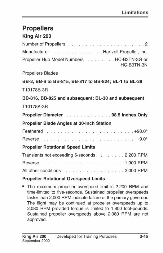
PropellersKing Air 200
Number of Propellers . . . . . . . . . . . . . . . . . . . . . . 2
Manufacturer . . . . . . . . . . . . . . Hartzell Propeller, Inc.
Propeller Hub Model Numbers . . . . . . . . HC-B3TN-3G or . . . . . . . . . . . . . . . . . . . . . . . . . . .HC-B3TN-3N
Propellers Blades
BB-2, BB-6 to BB-815, BB-817 to BB-824; BL-1 to BL-29
T10178B-3R
BB-816, BB-825 and subsequent; BL-30 and subsequent
T10178K-3R
Propeller Diameter . . . . . . . . . . . . . 98.5 Inches Only
Propeller Blade Angles at 30-Inch Station
Feathered . . . . . . . . . . . . . . . . . . . . . . . . . +90.0°
Reverse . . . . . . . . . . . . . . . . . . . . . . . . . . . -9.0°
Propeller Rotational Speed Limits
Transients not exceeding 5-seconds . . . . . . . 2,200 RPM
Reverse . . . . . . . . . . . . . . . . . . . . . . . 1,900 RPM
All other conditions . . . . . . . . . . . . . . . . . 2,000 RPM
Propeller Rotational Overspeed Limits
■ The maximum propeller overspeed limit is 2,200 RPM andtime-limited to five-seconds. Sustained propeller overspeedsfaster than 2,000 RPM indicate failure of the primary governor.The flight may be continued at propeller overspeeds up to2,080 RPM provided torque is limited to 1,800 foot-pounds.Sustained propeller overspeeds above 2,080 RPM are notapproved.

3-46 Developed for Training Purposes King Air 200September 2002
CAE SimuFlite
King Air B200 - S/Ns BB-743 to 1143 with exceptions;BL-37 to 138
Number of Propellers . . . . . . . . . . . . . . . . . . . . . 2
Manufacturer . . . . . Hartzell Propeller, Inc., Piqua, Ohio . . . . . . . . . . . . .McCauley Propeller, Vandalia, Ohio
Propeller Hub and Model Numbers
Propeller Diameter
Hartzell . . . . . . . . . . . . . . . . . . . . . 98.5 Inches Only
McCauley . . . . . . . . . . . . . . . . . . . 98.0 Inches Only
Propeller Blade Angles at 30-Inch Station
Hartzell Feathered . . . . . . . . . . . . . . . . . . . . +90.0°
Hartzell Reverse . . . . . . . . . . . . . . . . . . . . . . -9.0°
McCauley Feathered . . . . . . . . . . . . . . . . . . . +86.8°
McCauley Reverse . . . . . . . . . . . . . . . . . . . . -10.0°
Propeller Rotational Speed Limits
Transients not exceeding 5-seconds . . . . . . . 2,200 RPM
Reverse . . . . . . . . . . . . . . . . . . . . . . . 1,900 RPM
All other conditions . . . . . . . . . . . . . . . . . 2,000 RPM
Propeller Rotational Overspeed Limits
■ The maximum propeller overspeed limit is 2,200 RPM andtime-limited to five-seconds. Sustained propeller overspeedsfaster than 2,000 RPM indicate failure of the primary gover-nor. Flight may be continued at propeller overspeeds up to2,080 RPM provided torque is limited to 1,800 foot-pounds.Sustained propeller overspeeds greater than 2,080 RPM arenot approved.*
*2,120 RPM (BB-1444 and subsequent).

King Air 200 Developed for Training Purposes 3-47September 2002
Limitations
King Air B-200 - S/Ns BB-1439 and subsequent withexceptions; BL-139 and subsequent; BW-1 and subsequentNumber of Propellers . . . . . . . . . . . . . . . . . . . . . 2
Manufacturer . . . . . Hartzell Propeller, Inc., Piqua, Ohio . . . . . . . . . . . . .McCauley Propeller, Vandalia, Ohio
Propeller Hub and Blade Model Numbers
Hartzell Hub . . . . . . . . . . . . . . . . . . . . . HC-E4N-3G
Hartzell Blades . . . . . . . . . . . . . . . . . . D9390SK-1R
McCauley Hub . . . . . . . . . . . . . . . . . 4HFR34C771-X
McCauley Blades . . . . . . . . . . . . . . . . . . . X-94LA-0
■ The letter appearing in the place of the X represents minorvariations in the propeller hub or blades. They do not effectthe eligibility or interchangeability.
Propeller Diameter
Hartzell . . . . . . . . . . . . . . . . . . 93.0 INCHES (MAX) . . . . . . . . . . . . . . . . . . . . . . . .92.0 INCHES (MIN)
McCauley . . . . . . . . . . . . . . . . . 94.0 INCHES (MAX) . . . . . . . . . . . . . . . . . . . . . . . .93.5 INCHES (MIN)
Propeller Blade Angles at 30-Inch Station
Hartzell Feathered . . . . . . . . . . . . . . . . . . . . +87.9°
Hartzell Reverse . . . . . . . . . . . . . . . . . . . . . . -11.2°
McCauley Feathered . . . . . . . . . . . . . . . . . . . +87.5°
McCauley Reverse . . . . . . . . . . . . . . . . . . . . -10.0°

3-48 Developed for Training Purposes King Air 200September 2002
CAE SimuFlite
Propeller Rotational Speed Limits
Transients not exceeding 5-seconds . . . . . . . 2,200 RPM
Reverse . . . . . . . . . . . . . . . . . . . . . . . 1,900 RPM
All other conditions . . . . . . . . . . . . . . . . . 2,000 RPM
Minimum Idle Speed
Hartzell Propellers . . . . . . . . . . . . . . . . . . 1,180 RPM
McCauley Propellers . . . . . . . . . . . . . . . . 1,100 RPM
Propeller Rotational Overspeed Limits
■ The maximum propeller overspeed limit is 2,200 RPM andtime-limited to five-seconds. Sustained propeller overspeedsfaster than 2,000 RPM indicate failure of the primary governor.The flight may be continued at propeller overspeeds up to2,080 RPM provided torque is limited to 1,800 foot-pounds.Sustained propeller overspeeds above 2,080 RPM (2,120 RPM;SNs BB-1444 and subsequent) are not approved.


![Crosswind Guidelines[1]](https://static.fdocuments.in/doc/165x107/542d898f219acd4d4b8b573b/crosswind-guidelines1.jpg)