Limit Switch Stylefuchs-nj...Inductive Surface Mount Inductive Proximity Sensors 104 Pepperl+Fuchs...
11
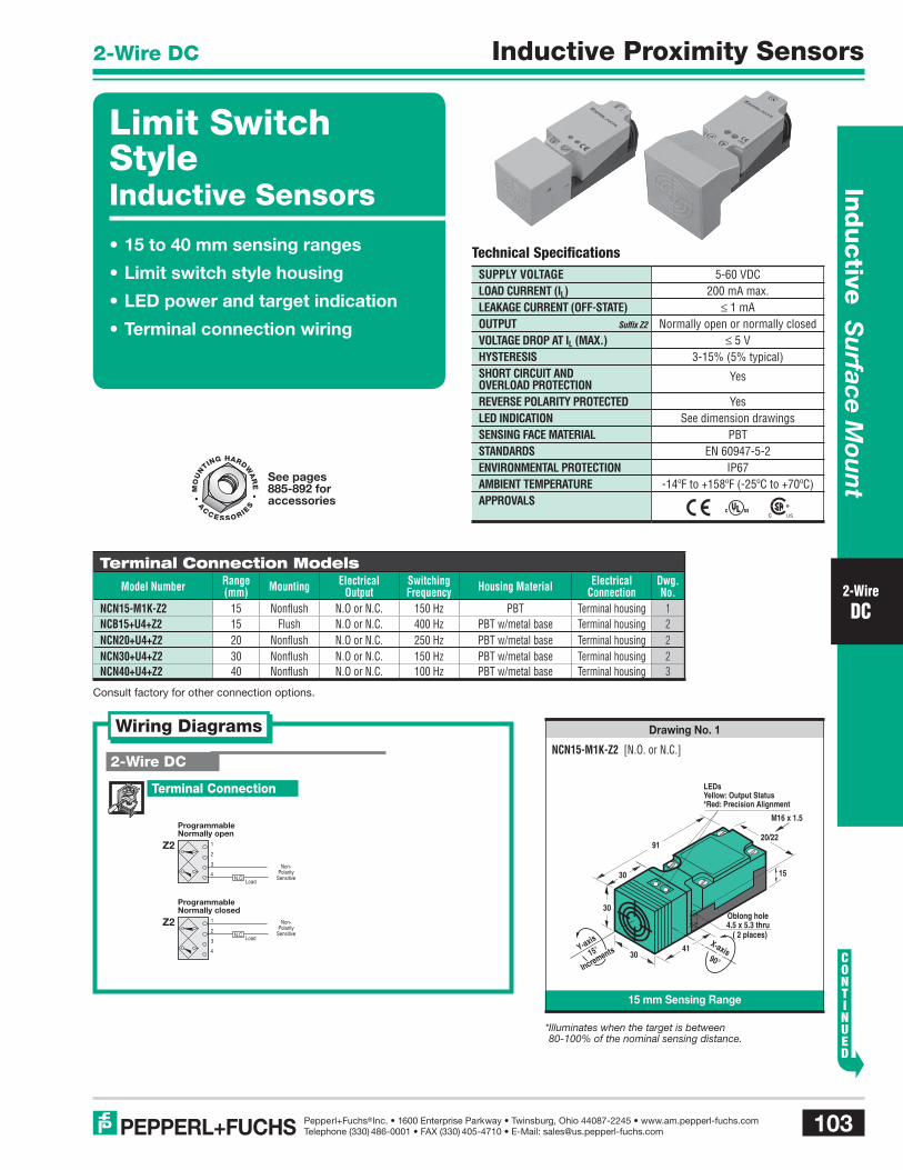
Inductive Surface Mount 103 Pepperl+Fuchs Inc. • 1600 Enterprise Parkway • Twinsburg, Ohio 44087-2245 • www.am.pepperl-fuchs.com Telephone (330) 486-0001 • FAX (330) 405-4710 • E-Mail: [email protected] ® PEPPERL+FUCHS Inductive Proximity Sensors 2-Wire DC 2-Wire DC 15 mm Sensing Range Drawing No. 1 NCN15-M1K-Z2 [N.O. or N.C.] Technical Specifications SUPPLY VOLTAGE LOAD CURRENT (I L ) LEAKAGE CURRENT (OFF-STATE) OUTPUT Suffix Z2 VOLTAGE DROP AT I L (MAX.) HYSTERESIS SHORT CIRCUIT AND OVERLOAD PROTECTION REVERSE POLARITY PROTECTED LED INDICATION SENSING FACE MATERIAL STANDARDS ENVIRONMENTAL PROTECTION AMBIENT TEMPERATURE APPROVALS 5-60 VDC 200 mA max. ≤ 1 mA Normally open or normally closed ≤ 5 V 3-15% (5% typical) Yes Yes See dimension drawings PBT EN 60947-5-2 IP67 -14ºF to +158ºF (-25ºC to +70ºC) Terminal Connection Models Model Number Range (mm) Mounting Electrical Output Switching Frequency Housing Material Electrical Connection Dwg. No. NCN15-M1K-Z2 15 Nonflush N.O or N.C. 150 Hz PBT Terminal housing 1 NCB15+U4+Z2 15 Flush N.O or N.C. 400 Hz PBT w/metal base Terminal housing 2 NCN20+U4+Z2 20 Nonflush N.O or N.C. 250 Hz PBT w/metal base Terminal housing 2 NCN30+U4+Z2 30 Nonflush N.O or N.C. 150 Hz PBT w/metal base Terminal housing 2 NCN40+U4+Z2 40 Nonflush N.O or N.C. 100 Hz PBT w/metal base Terminal housing 3 Wiring Diagrams 2-Wire DC Terminal Connection Z2 Programmable Normally closed 1 2 Load 3 4 N.C. Non- Polarity Sensitive Z2 Programmable Normally open 1 2 3 4 Load N.O. Non- Polarity Sensitive 15 Oblong hole 4.5 x 5.3 thru ( 2 places) 91 30 30 20/22 41 Y-axis 90° 15° Increments X-axis 30 M16 x 1.5 LEDs Yellow: Output Status *Red: Precision Alignment *Illuminates when the target is between 80-100% of the nominal sensing distance. Limit Switch Style Inductive Sensors • 15 to 40 mm sensing ranges • Limit switch style housing • LED power and target indication • Terminal connection wiring Consult factory for other connection options. See pages 885-892 for accessories
Transcript of Limit Switch Stylefuchs-nj...Inductive Surface Mount Inductive Proximity Sensors 104 Pepperl+Fuchs...
In
du
ctive
Su
rface Mou
nt
103Pepperl+Fuchs Inc. • 1600 Enterprise Parkway • Twinsburg, Ohio 44087-2245 • www.am.pepperl-fuchs.comTelephone (330) 486-0001 • FAX (330) 405-4710 • E-Mail: [email protected]
®PEPPERL+FUCHS
Inductive Proximity Sensors2-Wire DC
2-WireDC
15 mm Sensing Range
Drawing No. 1
NCN15-M1K-Z2 [N.O. or N.C.]
Technical Specifi cationsSUPPLY VOLTAGELOAD CURRENT (IL)LEAKAGE CURRENT (OFF-STATE)OUTPUT Suffi x Z2
VOLTAGE DROP AT IL (MAX.)HYSTERESISSHORT CIRCUIT AND OVERLOAD PROTECTIONREVERSE POLARITY PROTECTEDLED INDICATIONSENSING FACE MATERIALSTANDARDSENVIRONMENTAL PROTECTIONAMBIENT TEMPERATUREAPPROVALS
5-60 VDC200 mA max.
≤ 1 mANormally open or normally closed
≤ 5 V3-15% (5% typical)
Yes
YesSee dimension drawings
PBTEN 60947-5-2
IP67-14ºF to +158ºF (-25ºC to +70ºC)
Terminal Connection ModelsModel Number Range
(mm) Mounting Electrical Output
Switching Frequency Housing Material Electrical
ConnectionDwg. No.
NCN15-M1K-Z2 15 Nonfl ush N.O or N.C. 150 Hz PBT Terminal housing 1NCB15+U4+Z2 15 Flush N.O or N.C. 400 Hz PBT w/metal base Terminal housing 2NCN20+U4+Z2 20 Nonfl ush N.O or N.C. 250 Hz PBT w/metal base Terminal housing 2NCN30+U4+Z2 30 Nonfl ush N.O or N.C. 150 Hz PBT w/metal base Terminal housing 2NCN40+U4+Z2 40 Nonfl ush N.O or N.C. 100 Hz PBT w/metal base Terminal housing 3
Wiring Diagrams
2-Wire DC
Terminal Connection
Z2
ProgrammableNormally closed
1
2Load3
4
N.C.
Non-Polarity
Sensitive
Z2
ProgrammableNormally open
1
2
3
4Load
N.O.
Non-Polarity
Sensitive15
Oblong hole4.5 x 5.3 thru
( 2 places)
91
30
30
20/22
41Y-axis
90°15°
IncrementsX-axis
30
M16 x 1.5
LEDsYellow: Output Status*Red: Precision Alignment
* Illuminates when the target is between 80-100% of the nominal sensing distance.
Limit Switch Style Inductive Sensors
• 15 to 40 mm sensing ranges
• Limit switch style housing
• LED power and target indication
• Terminal connection wiring
Consult factory for other connection options.
See pages 885-892 for accessories

In
ducti
ve
Su
rfac
e M
oun
tInductive Proximity Sensors
104 Pepperl+Fuchs Inc. • 1600 Enterprise Parkway • Twinsburg, Ohio 44087-2245 • www.am.pepperl-fuchs.comTelephone (330) 486-0001 • FAX (330) 405-4710 • E-Mail: [email protected]
®PEPPERL+FUCHS
2-Wire DC
2-WireDC
15, 20, and 30 mm Sensing Range
Drawing No. 2
NCB15+U4+Z2 [N.O. or N.C.]NCN20+U4+Z2 [N.O. or N.C.]NCN30+U4+Z2 [N.O. or N.C.]
1/2" NPT
11
5.3 thru
Oblong hole5.3 x 7.3 thru
( 2 places )
118
40
40
40X-axis90
30
( 2 places )
46
60
Y-axis
90
Increments
LEDYellow: Output Status*Red: Precision Alignment
5.5 thru
Oblong hole5.3 x 7.3 thru
( 2 places )
( 2 places )
11
55
5556
60
50
1/2" NPT
30(between
holes)
Y-axis
90°
Increments 90°
X-axis
128
LEDYellow: Output Status*Red: Precision Alignment
Limit Switch Style
40 mm Sensing Range
Drawing No. 3
NCN40+U4+Z2 [N.O. or N.C.]
* Illuminates when the target is between 80-100% of the nominal sensing distance.
Recommended Accessories
Mounting BracketsModel Description
MH4-2681 UNI Adjustable Unistrut® bracketMH4-2057 Adjustable slide bracket
OMH4-4950 Rotating bracket for mini limit switchMH4-3742 Adjustable bracket for mini limit switch
See pages 885-892 for complete accessory listing.
MH4-2681 UNIMH4-2057
OMH4-4950
MH4-3742

In
du
ctive
Su
rface Mou
nt
105Pepperl+Fuchs Inc. • 1600 Enterprise Parkway • Twinsburg, Ohio 44087-2245 • www.am.pepperl-fuchs.comTelephone (330) 486-0001 • FAX (330) 405-4710 • E-Mail: [email protected]
®PEPPERL+FUCHS
Inductive Proximity Sensors3-Wire and 4-Wire DC
3-Wireand
4-WireDC
Technical Specifi cationsSUPPLY VOLTAGE U4 and M1K Models
M1 Model
LOAD CURRENT (IL)LEAKAGE CURRENT (OFF-STATE)OUTPUT Suffi x E
Suffi x E2
Suffi x E4
Suffi x E5
Suffi x A
Suffi x A2
VOLTAGE DROP AT IL (MAX.)HYSTERESISSHORT CIRCUIT AND OVERLOAD PROTECTIONREVERSE POLARITY PROTECTEDLED INDICATIONSENSING FACE MATERIALSTANDARDSENVIRONMENTAL PROTECTIONAMBIENT TEMPERATUREAPPROVALS
10-60 VDC10-30 VDC
200 mA max.≤ 0.5 mA
NPN normally openPNP normally open
NPN normally open or normally closedPNP normally open or normally closedNPN normally open & normally closedPNP normally open & normally closed
≤ 3 V3-15% (5% typical)
Yes
YesSee dimension drawings
PBTEN 60947-5-2
IP67-14ºF to +158ºF (-25ºC to +70ºC)
Terminal Connection ModelsModel Number Range
(mm) Mounting Electrical Output
Switching Frequency Housing Material Electrical
ConnectionDwg. No.
NCN15-M1K-E4 15 Nonfl ush NPN N.O. or N.C. 500 Hz PBT Terminal housing 1NCN15-M1K-E5 15 Nonfl ush PNP N.O. or N.C. 500 Hz PBT Terminal housing 1NJ15+U4+E 15 Flush NPN N.O. 300 Hz PBT w/metal base Terminal housing 2NJ15+U4+E2 15 Flush PNP N.O. 300 Hz PBT w/metal base Terminal housing 2NJ15+U4+A 15 Flush NPN N.O. & N.C. 150 Hz PBT w/metal base Terminal housing 2NJ15+U4+A2 15 Flush PNP N.O. & N.C. 150 Hz PBT w/metal base Terminal housing 2NJ20+U4+E 20 Flush NPN N.O. 300 Hz PBT w/metal base Terminal housing 2NJ20+U4+E2 20 Flush PNP N.O. 300 Hz PBT w/metal base Terminal housing 2NJ20+U4+A2 20 Flush PNP N.O. & N.C. 150 Hz PBT w/metal base Terminal housing 2NJ30+U4+E 30 Nonfl ush NPN N.O. 300 Hz PBT w/metal base Terminal housing 2NJ30+U4+E2 30 Nonfl ush PNP N.O. 300 Hz PBT w/metal base Terminal housing 2NJ30+U4+A 30 Nonfl ush NPN N.O. & N.C. 150 Hz PBT w/metal base Terminal housing 2NJ30+U4+A2 30 Nonfl ush PNP N.O. & N.C. 150 Hz PBT w/metal base Terminal housing 2NJ40+U4+E 40 Nonfl ush NPN N.O. 100 Hz PBT w/metal base Terminal housing 3NJ40+U4+E2 40 Nonfl ush PNP N.O. 100 Hz PBT w/metal base Terminal housing 3NCN40+U4+E2 40 Nonfl ush PNP N.O. 30 Hz PBT w/metal base Terminal housing 2NJ40+U4+A 40 Nonfl ush NPN N.O. & N.C. 150 Hz PBT w/metal base Terminal housing 3NJ40+U4+A2 40 Nonfl ush PNP N.O. & N.C. 150 Hz PBT w/metal base Terminal housing 3NCN40+U4+A2 40 Nonfl ush PNP N.O. & N.C. 30 Hz PBT w/metal base Terminal housing 2
Micro (M12) Quick Disconnect ModelsModel Number Range
(mm) Mounting Electrical Output
Switching Frequency Housing Material Electrical
ConnectionDwg. No.
NJ15-M1-E2-V1 15 Nonfl ush PNP N.O. 500 Hz PBT w/metal base M12 Micro 4
X-SeriesTM
Sensing range 25-240% beyond “traditional” inductive sensors
Look for this logo in the drawings to identify our X-Series extended range sensors
Limit Switch Style Inductive Sensors
• 15 to 40 mm sensing ranges
• Limit switch style housing
• LED power and target indication
• Terminal connection wiring
Consult factory for other connection options.
See pages 885-892 for accessories
See pages 827-874 for cordsets

In
ducti
ve
Su
rfac
e M
oun
tInductive Proximity Sensors
106 Pepperl+Fuchs Inc. • 1600 Enterprise Parkway • Twinsburg, Ohio 44087-2245 • www.am.pepperl-fuchs.comTelephone (330) 486-0001 • FAX (330) 405-4710 • E-Mail: [email protected]
®PEPPERL+FUCHS
3-Wire and 4-Wire DC
3-Wireand
4-WireDC
15, 20, 30, and 40 mm Sensing Range
Drawing No. 2
NJ30+U4+E [NPN N.O.]NJ30+U4+E2 [PNP N.O.]NJ30+U4+A [NPN N.O. & N.C.]NJ30+U4+A2 [PNP N.O. & N.C.]NCN40+U4+E2 [PNP N.O.]NCN40+U4+A2 [PNP N.O. & N.C.]
15 mm Sensing Range
Drawing No. 1
NCN15-M1K-E4 [NPN N.O. or N.C.]NCN15-M1K-E5 [PNP N.O. or N.C.]
Wiring Diagrams
Male Receptacle End View
PNP Normally openE2 1 Brown
4 Black
3 BlueLoad
( )
( )
Black
Blue
Brown
1 2
34
Load
( )
( )
Note: Wiring diagrams show quick disconnect pin numbers.
Quick Disconnect
V1 Type
3-Wire DC
4-Wire DC
Terminal Connection
Terminal Connection
3
NPN Normally open1
4 LoadE
E0( )
( )
E2PNP Normally open
1
4
3Load
( )
( )
NPN Normally open1
4
3
LoadE4 ( )
( )
2
NPN Normally closed1
4
3
LoadE4 ( )
( )
2
A
NPN Normally openand Normally closed
1
4
2
3
N.O. LoadN.C. Load
( )
( )
A2
PNP Normally openand Normally closed
1
4
2
3 N.C. Load
N.O. Load
( )
( )
Limit Switch Style
4.3 x 5.3 thru ( 2 places)
15
Oblong hole
M16 x 1.5
30
91
30
30
20/22
41Y-axis
15°
Increments 90°
X-axis
LEDYellow: Output Status
11
5.3 thru
Oblong hole5.3 x 7.3 thru
( 2 places )
118
40
40
40
( 2 places )
46
60
Y-axis
90°
Increments90°
X-axis
1/2" NPT
30(between
holes)
LEDYellow: Output StatusGreen: Power
NJ15+U4+E [NPN N.O.]NJ15+U4+E2 [PNP N.O.]NJ15+U4+A [NPN N.O. & N.C.]NJ15+U4+A2 [PNP N.O. & N.C.]NJ20+U4+E [NPN N.O.]NJ20+U4+E2 [PNP N.O.]NJ20+U4+A2 [PNP N.O. & N.C.]
PNP Normally open1
4
3Load
E5 ( )
( )
2
PNP Normally closed1
4
3 Load
E5 ( )
( )
2

In
du
ctive
Su
rface Mou
nt
107Pepperl+Fuchs Inc. • 1600 Enterprise Parkway • Twinsburg, Ohio 44087-2245 • www.am.pepperl-fuchs.comTelephone (330) 486-0001 • FAX (330) 405-4710 • E-Mail: [email protected]
®PEPPERL+FUCHS
Inductive Proximity Sensors3-Wire and 4-Wire DC
3-Wireand
4-WireDC
40 mm Sensing Range
Drawing No. 3
Limit Switch Style
5.5 thru
Oblong hole5.3 x 7.3 thru
( 2 places )
( 2 places )
11
55
5556
60
50
1/2" NPT
30(between
holes)
Y-axis
90°
Increments 90°
X-axis
128
LEDsYellow: Output StatusGreen: Power
M12x1
Oblong hole
4.3 x 5.3 thru ( 2 places)
20/22
90°
X-axis
3015.5
7262
15
4130
30
Y-axis
15°
Increments
LEDYellow: Output Status
NJ40+U4+E [NPN N.O.]NJ40+U4+E2 [PNP N.O.]NJ40+U4+A [NPN N.O. & N.C.]NJ40+U4+A2 [PNP N.O. & N.C.]
15 mm Sensing Range
Drawing No. 4
NJ15-M1-E2-V1 [PNP N.O.]
Recommended Accessories
Mounting BracketsModel Description
MH4-2681 UNI Adjustable Unistrut® bracketMH4-2057 Adjustable slide bracket
OMH4-4950 Rotating bracket for mini limit switchMH4-3742 Adjustable bracket for mini limit switch
See pages 885-892 for complete accessory listing.
MH4-2681 UNIMH4-2057
OMH4-4950
MH4-3742

In
ducti
ve
Su
rfac
e M
oun
tInductive Proximity Sensors
108 Pepperl+Fuchs Inc. • 1600 Enterprise Parkway • Twinsburg, Ohio 44087-2245 • www.am.pepperl-fuchs.comTelephone (330) 486-0001 • FAX (330) 405-4710 • E-Mail: [email protected]
®PEPPERL+FUCHS
2-Wire AC
2-WireAC
Technical Specifi cationsSUPPLY VOLTAGESUPPLY FREQUENCYLOAD CURRENT (IL) NJ models
NBN models
LEAKAGE CURRENT (OFF-STATE)OUTPUT Suffi x WS
Suffi x W
VOLTAGE DROP AT IL (MAX.)INRUSH CURRENT NJ models
NBN models
HYSTERESISSHORT CIRCUIT AND OVERLOAD PROTECTIONREVERSE POLARITY PROTECTEDLED INDICATIONSENSING FACE MATERIALSTANDARDSENVIRONMENTAL PROTECTIONAMBIENT TEMPERATUREAPPROVALS
20-250 VAC45-65 Hz
500 mA max.400 mA max.
≤ 1.7 mANormally open
Normally open or normally closed≤ 5 V
≤ 4 A/20 ms≤ 2.4 A/20 ms
3-15% (5% typical)
No
NoSee dimension drawings
PBTEN 60947-5-2
IP67-14ºF to +158ºF (-25ºC to +70ºC)
Terminal Connection ModelsModel Number Range
(mm) Mounting Electrical Output
Switching Frequency Housing Material Electrical
ConnectionDwg. No.
NBN15-M1K-WS 15 Nonfl ush N.O. 20 Hz PBT Terminal housing 1NJ15+U4+W 15 Flush N.O. or N.C. 25 Hz PBT w/metal base Terminal housing 2NJ20+U4+W 20 Nonfl ush N.O. or N.C. 20 Hz PBT w/metal base Terminal housing 2NJ30+U4+W 30 Nonfl ush N.O. or N.C. 20 Hz PBT w/metal base Terminal housing 2NJ40+U4+W 40 Nonfl ush N.O. or N.C. 20 Hz PBT w/metal base Terminal housing 3
Mini AC/DC (7/8"-16) Quick Disconnect ModelsModel Number Range
(mm) Mounting Electrical Output
Switching Frequency Housing Material Electrical
ConnectionDwg. No.
NBN15-M1-WS-BHM 15 Nonfl ush N.O. 25 Hz PBT w/metal base 7/8"-16 Mini AC 4
Wiring Diagrams
Note: Wiring diagrams show quick disconnect pin numbers.
Quick Disconnect2-Wire AC
Terminal Connection
BHM Type Male Receptacle End View
WSNormally open
2 Black
3 WhiteLoad
1 Green(Metal Housing Only)
L2
L1
LoadWhite
Black
Green
(Metal Housing Only)
L1
L2
1
23
Limit Switch Style Inductive Sensors
• 15 to 40 mm sensing ranges
• Limit switch style housing
• LED power and target indication
• Terminal connection wiring
Normally open
4
3WSLoad
N
L1
Consult factory for other connection options.
W
ProgrammableNormally open
2
1
(Metal Base Only)
4
3 LoadL2
L1N.O.
W
ProgrammableNormally closed
2
1 Load
(Metal Base Only)
L2
L1
4
3
N.C.
See pages 885-892 for accessories
See pages 827-874 for cordsets

In
du
ctive
Su
rface Mou
nt
109Pepperl+Fuchs Inc. • 1600 Enterprise Parkway • Twinsburg, Ohio 44087-2245 • www.am.pepperl-fuchs.comTelephone (330) 486-0001 • FAX (330) 405-4710 • E-Mail: [email protected]
®PEPPERL+FUCHS
Inductive Proximity Sensors2-Wire AC
2-WireAC
15 mm Sensing Range
Drawing No. 1
15, 20, and 30 mm Sensing Range
Drawing No. 2
40 mm Sensing Range
Drawing No. 3
Limit Switch Style
4.3 x 5.3 thru ( 2 places)
15
Oblong hole
M16 x 1.5
30
91
30
30
20/22
41Y-axis
15°
Increments 90°
X-axis
LEDYellow: Output Status
11
5.3 thru
Oblong hole5.3 x 7.3 thru
( 2 places )
118
40
40
40
( 2 places )
46
60
Y-axis
90°
Increments90°
X-axis
1/2" NPT
30(between
holes)
LEDYellow: Output StatusGreen: Power
5.5 thru
Oblong hole5.3 x 7.3 thru
( 2 places )
( 2 places )
11
55
5556
60
50
1/2" NPT
30(between
holes)
Y-axis
90°
Increments 90°
X-axis
128
LEDsYellow: Output StatusGreen: Power
15 mm Sensing Range
Drawing No. 4
Oblong hole
4.3 x 5.3 thru ( 2 places)
20/22
90°
X-axis
3015.5
7262
7/8-16UN/2A
15
4130
30
Y-axis
15°
Increments
LEDsYellow: Output StatusGreen: Power
NBN15-M1K-WS [N.O.] NJ15+U4+W [N.O. or N.C.]NJ20+U4+W [N.O. or N.C.]NJ30+U4+W [N.O. or N.C.]
NJ40+U4+W [N.O. or N.C.] NBN15-M1-WS-BHM [N.O.]
Recommended Accessories
Mounting BracketsModel Description
MH4-2681 UNI Adjustable Unistrut® bracketMH4-2057 Adjustable slide bracket
OMH4-4950 Rotating bracket for mini limit switchMH4-3742 Adjustable bracket for mini limit switch
See pages 885-892 for complete accessory listing.
MH4-2681 UNI MH4-2057
OMH4-4950
MH4-3742

In
ducti
ve
Su
rfac
e M
oun
tInductive Proximity Sensors
110 Pepperl+Fuchs Inc. • 1600 Enterprise Parkway • Twinsburg, Ohio 44087-2245 • www.am.pepperl-fuchs.comTelephone (330) 486-0001 • FAX (330) 405-4710 • E-Mail: [email protected]
®PEPPERL+FUCHS
2-Wire AC
2-WireAC
Technical Specifi cationsSUPPLY VOLTAGESUPPLY FREQUENCYLOAD CURRENT (IL)LEAKAGE CURRENT (OFF-STATE)OUTPUT 923 Series
VOLTAGE DROP AT IL (MAX.)INRUSH CURRENT HYSTERESISSHORT CIRCUIT AND OVERLOAD PROTECTIONREVERSE POLARITY PROTECTEDLED INDICATIONSENSING FACE MATERIALSTANDARDSENVIRONMENTAL PROTECTIONAMBIENT TEMPERATUREAPPROVALS
20-250 VAC45-65 Hz
500 mA max.≤ 1.5 mA
Normally open≤ 8 V
≤ 1.2 A/20 ms3-15% (5% typical)
No
NoSee dimension drawings
PolyamideEN 60947-5-2
IP67-14ºF to +158ºF (-25ºC to +70ºC)
Terminal Connection ModelsModel Number Range
(mm) Mounting Electrical Output
Switching Frequency Housing Material Electrical
ConnectionDwg. No.
923H26Q-A7T-L 15 Flush N.O. 20 Hz Polyamide/die-cast zinc Terminal housing 1
Wiring Diagrams
2-Wire AC
Terminal Connection
Normally open
4
3923Series
Load
L1
L2
15 mm Sensing Range
Drawing No. 1
5.3 thru
39
59.7
51.3
121
39
39
29.441
45
10
39Y-axis
90°
Increments90°
X-axis
1/2" NPT
(betweenholes)
LEDYellow:Output Status
923H26Q-A7T-L [N.O.]
Limit Switch Style Inductive Sensors
• 15 mm sensing range
• Limit switch style housing
• LED target indication
• All-metal terminal housing
See pages 885-892 for accessories

In
du
ctive
Su
rface Mou
nt
111Pepperl+Fuchs Inc. • 1600 Enterprise Parkway • Twinsburg, Ohio 44087-2245 • www.am.pepperl-fuchs.comTelephone (330) 486-0001 • FAX (330) 405-4710 • E-Mail: [email protected]
®PEPPERL+FUCHS
Inductive Proximity Sensors4-Wire AC
4-WireAC
Technical Specifi cationsSUPPLY VOLTAGESUPPLY FREQUENCYLOAD CURRENT (IL)LEAKAGE CURRENT (OFF-STATE)OUTPUT Suffi x W4
VOLTAGE DROP AT IL (MAX.)INRUSH CURRENTHYSTERESISSHORT CIRCUIT AND OVERLOAD PROTECTIONREVERSE POLARITY PROTECTEDLED INDICATIONSENSING FACE MATERIALSTANDARDSENVIRONMENTAL NBN/923 modelsPROTECTION NJ models
AMBIENT TEMPERATUREAPPROVALS
20-250 VAC45-65 Hz
500 mA max.≤ 10 µA
Normally open & normally closed≤ 3 V
≤ 4 A/20 ms3-15% (5% typical)
No
NoSee dimension drawings
PBTEN 60947-5-2
IP67IP68
-14ºF to +158ºF (-25ºC to +70ºC)
Terminal Connection ModelsModel Number Range
(mm) Mounting Electrical Output
Switching Frequency Housing Material Electrical
ConnectionDwg. No.
NJ15+U4+W4 15 Flush N.O. & N.C. 25 Hz PBT w/metal base Terminal housing 1NJ20+U4+W4 20 Nonfl ush N.O. & N.C. 20 Hz PBT w/metal base Terminal housing 1NJ30+U4+W4 30 Nonfl ush N.O & N.C. 25 Hz PBT w/metal base Terminal housing 1NJ40+U4+W4 40 Nonfl ush N.O. & N.C. 25 Hz PBT w/metal base Terminal housing 2
Wiring Diagrams
4-Wire AC
Terminal Connection
(Metal Base Only)
W4
Normally open andNormally closed
2
1 L2
4
3 L1
N.C. LoadN.O. Load
15, 20, and 30 mm Sensing Range
Drawing No. 1
NJ15+U4+W4 [N.O. & N.C.]NJ20+U4+W4 [N.O. & N.C.]NJ30+U4+W4 [N.O. & N.C.]
11
5.3 thru
Oblong hole5.3 x 7.3 thru
( 2 places )
118
40
40
40
( 2 places )
46
60
Y-axis
90°
Increments90°
X-axis
1/2" NPT
30(between
holes)
LEDsYellow: Normally OpenGreen: Normally Closed
Limit Switch Style Inductive Sensors
• 15 to 40 mm sensing ranges
• Limit switch style housing
• LED power and target indication
• Terminal connection wiring
Consult factory for other connection options.
See pages 885-892 for accessories

In
ducti
ve
Su
rfac
e M
oun
tInductive Proximity Sensors
112 Pepperl+Fuchs Inc. • 1600 Enterprise Parkway • Twinsburg, Ohio 44087-2245 • www.am.pepperl-fuchs.comTelephone (330) 486-0001 • FAX (330) 405-4710 • E-Mail: [email protected]
®PEPPERL+FUCHS
4-Wire AC
4-WireAC
40 mm Sensing Range
Drawing No. 2
NJ40+U4+W4 [N.O. & N.C.]
Limit Switch Style
5.5 thru
Oblong hole5.3 x 7.3 thru
( 2 places )
( 2 places )
11
55
5556
60
50
1/2" NPT
30(between
holes)
Y-axis
90
Increments 90
X-axis
128
LEDsYellow: Normally OpenGreen: Normally Closed
Recommended Accessories
Mounting BracketsModel Description
MH4-2681 UNI Adjustable Unistrut® bracketMH4-2057 Adjustable slide bracket
See pages 885-892 for complete accessory listing.
MH4-2681 UNIMH4-2057