LIGO-G050427-00-D 1 Coupled Dynamics of Payload Structures on the Seismically Isolated Optics Table...
18
1 LIGO-G050427-00-D Coupled Dynamics of Payload Structures on the Seismically Isolated Optics Table Dennis Coyne, LIGO Caltech SWG Meeting, 2 Sep 2005
-
Upload
ira-barton -
Category
Documents
-
view
216 -
download
0
Transcript of LIGO-G050427-00-D 1 Coupled Dynamics of Payload Structures on the Seismically Isolated Optics Table...

1LIGO-G050427-00-D
Coupled Dynamics of Payload Structures on the Seismically
Isolated Optics Table
Dennis Coyne, LIGO Caltech
SWG Meeting, 2 Sep 2005

2LIGO-G050427-00-D
Seismic Isolation (SEI) System &Suspension System (SUS)
Calculated perturbation to the SEI transfer functions due to the addition of the payload structures on the BSC optics table, e.g. quadruple SUS structure Gain & phase variations must not destabilize the active SEI controls Should not unduly increase in the control law complexity (decrease robustness) Current planned upper unity gain frequency for the SEI system is about 60 Hz.
The stiffness requirements of the seismic isolation inner stage structure are essentially that: the phase lag is less than 90 degrees below 150 Hz for the transfer function from each actuator
(force) to each non-collocated sensor (displacement), and the phase lag is less than 90 degrees below 500 Hz for the transfer function from each actuator
(force) to each collocated sensor (displacement)
Wanted SUS quad structure 1st resonance > 150 Hz (for attachment to a perfectly stiff interface) found impossible to meet, within the mass and envelope allocations
Current SUS working baseline goal is as follows: SUS design has provision to un-couple the lower structure from the upper structure & support the
lower structure from the support tubes of the chamber > 200 Hz 1st resonance for the upper quad SUS structure > 100 Hz 1st resonance for lower quad SUS structure > 100 Hz 1st resonance for combined upper and lower quad SUS structure

3LIGO-G050427-00-D
Sensor & Actuator Locations Keel Mass
Optics Table
Stage 2 Primary Structure
A A
Vertical L4C geophone (stage 1, typ 3 places)
Stage1 Primary Structure
Stage2 Primary Structure
Vertical GS13 geophone (stage 2, typ. 3 places)
Horizontal GS13 geophone (stage 2, typ. 3 places)
Horizontal L4C geophone (stage 1, typ. 3 places)
Horizontal Stage1-2 Actuator (typical, 3 places)
Vertical Stage1-2 Actuator (typical, 3 places)
3 axis, STS-2 seismometer (stage 1, typ. 3 places)

4LIGO-G050427-00-D
ASI FEA Model Considers payload total mass and center-of-mass position, but not flexibility
of the payload (i.e. quad structure The total stage2 mass is 14.48 lbf-s2/inch (slinch) or 5591 lbm or 2536 kg
payload mass of 450 kg "keel" ballast of 633 kg stage2 structure mass of 1454 kg
Used this Stage2 FEM for coupled dynamics analysis with Quadruple Pendulum (non-suspended) Mass/structure

5LIGO-G050427-00-D
Stage 2 Modeswith Rigid Body Payload
Rigid Body Modes(flexures not modeled)
Seismometer/mount modes
Large Scale Elastic Modes
6LIGO-G050427-00-D
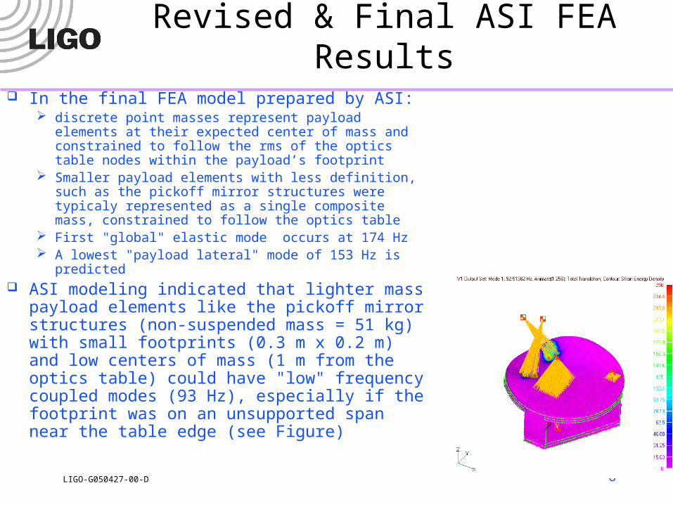
Revised & Final ASI FEA Results In the final FEA model prepared by ASI:
discrete point masses represent payload elements at their expected center of mass and constrained to follow the rms of the optics table nodes within the payload’s footprint
Smaller payload elements with less definition, such as the pickoff mirror structures were typicaly represented as a single composite mass, constrained to follow the optics table
First "global" elastic mode occurs at 174 Hz A lowest "payload lateral" mode of 153 Hz is predicted
ASI modeling indicated that lighter mass payload elements like the pickoff mirror structures (non-suspended mass = 51 kg) with small footprints (0.3 m x 0.2 m) and low centers of mass (1 m from the optics table) could have "low" frequency coupled modes (93 Hz), especially if the footprint was on an unsupported span near the table edge (see Figure)

7LIGO-G050427-00-D
Simple Beam and Rigid Mass Model
Cantilevered uniform beam is a reasonable first order approximation to the quad suspension structure
Simple beam connected to a rigid stage2 mass (Figure) is a reasonable approximation to the low frequency coupled dynamics of a suspension structure and the stage2 structure the first elastic mode of the suspension structure is likely about
100 Hz the first stage2 "global" structure elastic mode is ~174 Hz
(including payload mass loading) the suspension structure footprint is large relative to the optics
table (and so should not couple to local table/structure compliance).
R
C
RM
CM
actH
actV
A
bdbeam
r
actr
x
y
X
Y
stage2m
RIGIDBODY
BEAM

8LIGO-G050427-00-D
Beam/Mass and FEM Comparison
Semi-quantitative agreement between simple model and detailed FEM
-180
-170
-160
-150
-140
-130
-120
Ma
gn
itu
de
(d
B)
102
-180
-135
-90
-45
0
Ph
as
e (
de
g)
XYZrXrYrZ
Stage2 + Quad D040519-04, Rigid Body Modal (Cartesian) Actuation: Diagonal Response
Frequency (Hz)
Beam + Rigid Body Model Finite Element Model
9LIGO-G050427-00-D
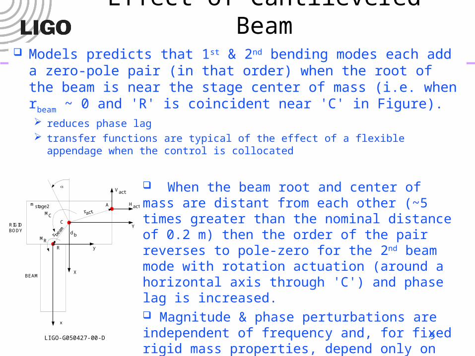
Effect of Cantilevered Beam Models predicts that 1st & 2nd bending modes each add a
zero-pole pair (in that order) when the root of the beam is near the stage center of mass (i.e. when rbeam ~ 0 and 'R' is
coincident near 'C' in Figure). reduces phase lag transfer functions are typical of the effect of a flexible appendage when the
control is collocated
R
C
RM
CM
actH
actV
A
bdbeam
r
actr
x
y
X
Y
stage2m
RIGIDBODY
BEAM
When the beam root and center of mass are distant from each other (~5 times greater than the nominal distance of 0.2 m) then the order of the pair reverses to pole-zero for the 2nd beam mode with rotation actuation (around a horizontal axis through 'C') and phase lag is increased. Magnitude & phase perturbations are independent of frequency and, for fixed rigid mass properties, depend only on the beam mass and modal damping factor

10LIGO-G050427-00-D
Horizontal Translation:Gain & Phase Changes versus Beam Mass
(with varying damping factor)
Points are FEA results for 2 suspension structure designs with a damping factor of 0.01
Curves are for damping factor varying from .5% to 8%. The bold black curve is for 1% damping.
0 100 200 300 400Beam MassKg0
10
20
30
40
50
edutingaMegnahC,
Bd
Horizontal Translation Magnitude Change0.005,0.01,0.015,0.02,0.03,0.04,0.05,0.06,0.08
0 100 200 300 400Beam MassKg0
25
50
75
100
125
150
esahP
egnah
C,
ged
Horizontal Translation Phase Change
0.005,0.01,0.015,0.02,0.03,0.04,0.05,0.06,0.08
11LIGO-G050427-00-D
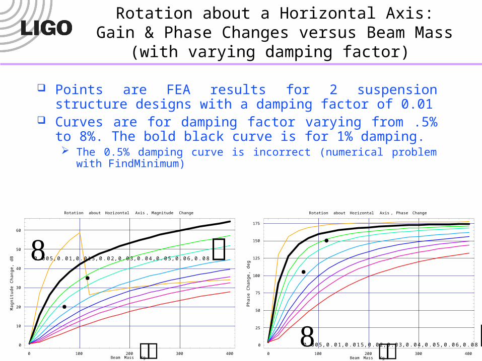
Rotation about a Horizontal Axis:Gain & Phase Changes versus Beam Mass
(with varying damping factor)
Points are FEA results for 2 suspension structure designs with a damping factor of 0.01
Curves are for damping factor varying from .5% to 8%. The bold black curve is for 1% damping. The 0.5% damping curve is incorrect (numerical problem with
FindMinimum)
0 100 200 300 400Beam MassKg0
10
20
30
40
50
60
edut
ingaM
egna
hC,
Bd
Rotation about Horizontal Axis , Magnitude Change
0.005,0.01,0.015,0.02,0.03,0.04,0.05,0.06,0.08
0 100 200 300 400Beam MassKg0
25
50
75
100
125
150
175
esahPegnahC,
ged
Rotation about Horizontal Axis , Phase Change
0.005,0.01,0.015,0.02,0.03,0.04,0.05,0.06,0.08

12LIGO-G050427-00-D
Practicalities Upper unity gain frequency of SEI stage 2 controls is ~ 60Hz, so would like
payload 1st frequency > ~150 Hz Without ‘exotic’ (non-UHV?) materials, this is impractical for a 2 m x [0.5 m x 0.7 m] footprint
cantilevered structure within the structure mass budget of 70 kg and non-suspended, non-structural mass of 70 kg
Truss frames (e.g. quadx33) that violate the “shrink wrap” footprint can achieve > 150 Hz (likely at higher mass than current budget)
Alternatively make structure light &/or heavily damped and let 1st frequency be low For small perturbations (say <~6 dB & <~30 deg), then the payload must have mass <~30 kg
for 1% damping, or < ~100 kg for 4% damping Since the non-structural mass is estimated to be ~70 kg (T030137-05), light weighting can
only be achieved by supporting the lower section of the quad structure from the crossbeams 4% damping might be possible with UHV-compatible, tuned mass damper – adding
broadband damping to structure in UHV-compatible manner seems difficult

13LIGO-G050427-00-D
Quad Structures Explored
Name Description Mass (kg) Freq. (Hz)
quadx33 structure with outriggers, heavy, high frequency
214 147, 153, 163, 168, …
quadx51 light, low frequency 84 total 77, 91, 150, 157, 189, …
quady2 lighter still, lower half light weight and flexible
70 total (9 lower)
27, 86, 91, 93, 123, …
D040519-04 medium mass, design used for quad SUS controls prototype
115 total 38 lower
86, 101, 102, 108, …
Impractical – violates envelope
Impractical (with current design paradigm) – lower structure doesn’t support assembly fixtures/procedures
Approximates the Controls Prototype being assembled now

14LIGO-G050427-00-D
Single Actuator to Sensor Transfer Functions
Significant phase excursions at Quad Structure resonance for the transfer function from a single actuator to a non-collocated sensor, e.g. V1 actuation to V3 displacement response
-200
-190
-180
-170
-160
-150
-140
-130
-120
-110
-100
Ma
gn
itu
de
(d
B)
102
-180
-90
0
90
180
Ph
as
e (
de
g)
V1V2V3H1H2H3
Stage2 + Quad D040519-04, Actuation: V1
Frequency (Hz)
All of the single actuation to collocated (adjacent) sensors have zero-pole pairs and positive phase excursions associated with the payload modes

15LIGO-G050427-00-D
Modal Transfer Functions Combined the actuator to sensor transfer functions (6 actuators x 6 sensor locations x 6 dof = 216
transfer functions) into cartesian modal transfer functions Rotational modes have been multiplied by the distance from the center of mass to the sensor locations,
so that they can be compared to the translational modes
-180
-170
-160
-150
-140
-130
-120
Ma
gn
itu
de
(d
B)
102
-180
-135
-90
-45
0
Ph
as
e (
de
g)
XYZrXrYrZ
Stage2 + Quad D040519-04, Rigid Body Modal (Cartesian) Actuation: Diagonal Response
Frequency (Hz)
All modal transfer functions have zero-pole pairings with positive phase perturbation, or no effect (modal actuation force has no component in the modal generalized force direction)

16LIGO-G050427-00-D
Cross-coupling
Significant cross coupling at the payload resonances For example, the X-mode transfer function has significant coupling to
rotation about the y-axis
-250
-200
-150
-100
-50
Ma
gn
itu
de
(d
B)
100
101
102
103
-180
-90
0
90
180
Ph
as
e (
de
g)
XYZrXrYrZ
Stage2 + Quad D040519-04, Rigid Body Modal (Cartesian) Actuation: X
Frequency (Hz)

17LIGO-G050427-00-D
Conclusions Given the high Q of the suspension structure mode, the control could
be destabilized if the control law does not explicitly compensate for the presence of the quad suspension induced feature in the transfer function If the SEI Stage-2 isolation control had a 1/f control law, then the positive phase
excursions caused by dynamic coupling to the quad structure would not be destabilizing
However the need for aggressive broad-band suppression of structural plant modes (at >~150 Hz) causes a lot of phase loss at the ~80-100 Hz quad suspension mode
Means to accommodate the coupled payload effect: compensate the gain peak due to the SUS coupling
– In principle could cancel the zero-pole pair introduced by the payload, and this might be stable (robust)
– Could use a broad notch (more robust?) and suffer a slightly lower upper unity gain frequency, and some slight feedback performance,
switch to local feedback control (instead of modal control), transition from modal feedback at low frequency to local feedback control at higher
frequencies, add damping to the SUS structure (UHV-compatible tuned mass damper?), or reduce the SUS structure first mode frequency (and thus the mass and coupling
magnitude) to be well below the upper unity gain frequency of the SEI control– However this requires a considerable departure from the current SUS structural design
Bottom Line: Quad Strucutre 1st frequency target of 100 Hz appears reasonable and can accommodated in the SEI Control

18LIGO-G050427-00-D
Further Work More careful consideration of the effect of the modal cross-coupling resulting
from the payload dynamics on the SEI control system design Use the more current ASI FEM for coupled analysis with the payloads
Better still; develop a more appropriate model for use in these dynamics studies. The current model has far too many degrees of freedom (more appropriate for a stress analysis)
Use a higher fidelity model for the SUS quad structure, D040519-04 The relatively simple FEM used herein has a first frequency of 82 Hz vs 100 Hz with more
detailed FEM The simple FEM used here also has some local modes which likely do not exist in the real
structure Develop a full stage 0, 1, 2 and suspension system (pendulums and structure)
model and use it to export a state space model for control system work in Matlab
Study the effect of a small footprint payload with a more significant lower end mass (such as the current concept for a pickoff mirror). While there is likely to be significant elastic coupling in this scenario, the result should not compromise the collocation of the SEI sensing and actuation
Test for coupled dynamics with a representative SUS structure on the SEI ETF system at Stanford Copy of the Quad Controls Prototype structure to be delivered to Stanford ~September