Lighting series JSS Lighting series JBS Lighting series JSH Lighting series JBH Lighting series
LIGHTING – LIGHTING SYSTEM LI–1
I
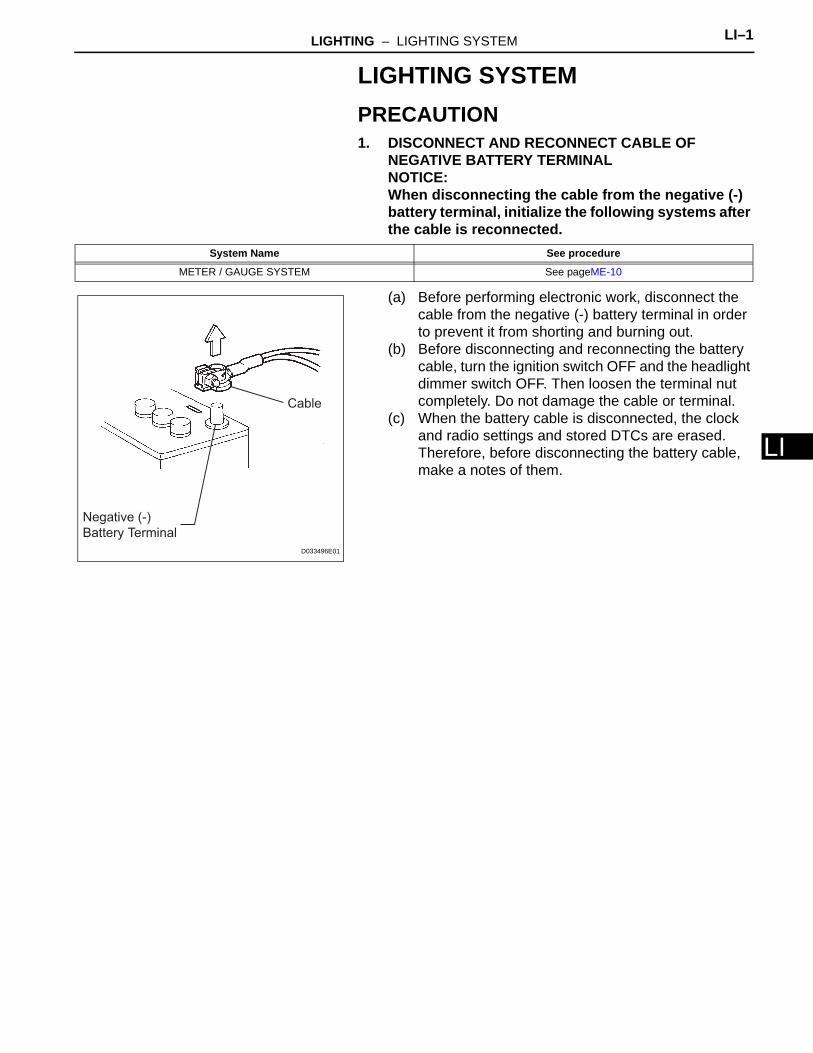
LLIGHTING SYSTEMPRECAUTION1. DISCONNECT AND RECONNECT CABLE OF
NEGATIVE BATTERY TERMINALNOTICE:When disconnecting the cable from the negative (-) battery terminal, initialize the following systems after the cable is reconnected.
(a) Before performing electronic work, disconnect the cable from the negative (-) battery terminal in order to prevent it from shorting and burning out.
(b) Before disconnecting and reconnecting the battery cable, turn the ignition switch OFF and the headlight dimmer switch OFF. Then loosen the terminal nut completely. Do not damage the cable or terminal.
(c) When the battery cable is disconnected, the clock and radio settings and stored DTCs are erased. Therefore, before disconnecting the battery cable, make a notes of them.
System Name See procedure
METER / GAUGE SYSTEM See pageME-10
Negative (-)
Battery Terminal
Cable
D033496E01
LI–2 LIGHTING – LIGHTING SYSTEM
LI
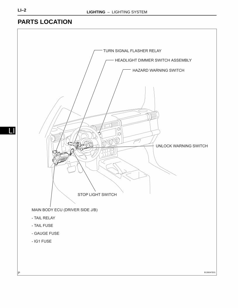
PARTS LOCATION
HEADLIGHT DIMMER SWITCH ASSEMBLY
- TAIL RELAY
TURN SIGNAL FLASHER RELAY
STOP LIGHT SWITCH
UNLOCK WARNING SWITCH
MAIN BODY ECU (DRIVER SIDE J/B)
- TAIL FUSE
- GAUGE FUSE
- IG1 FUSE
HAZARD WARNING SWITCH
B136047E01
LIGHTING – LIGHTING SYSTEM LI–3
I
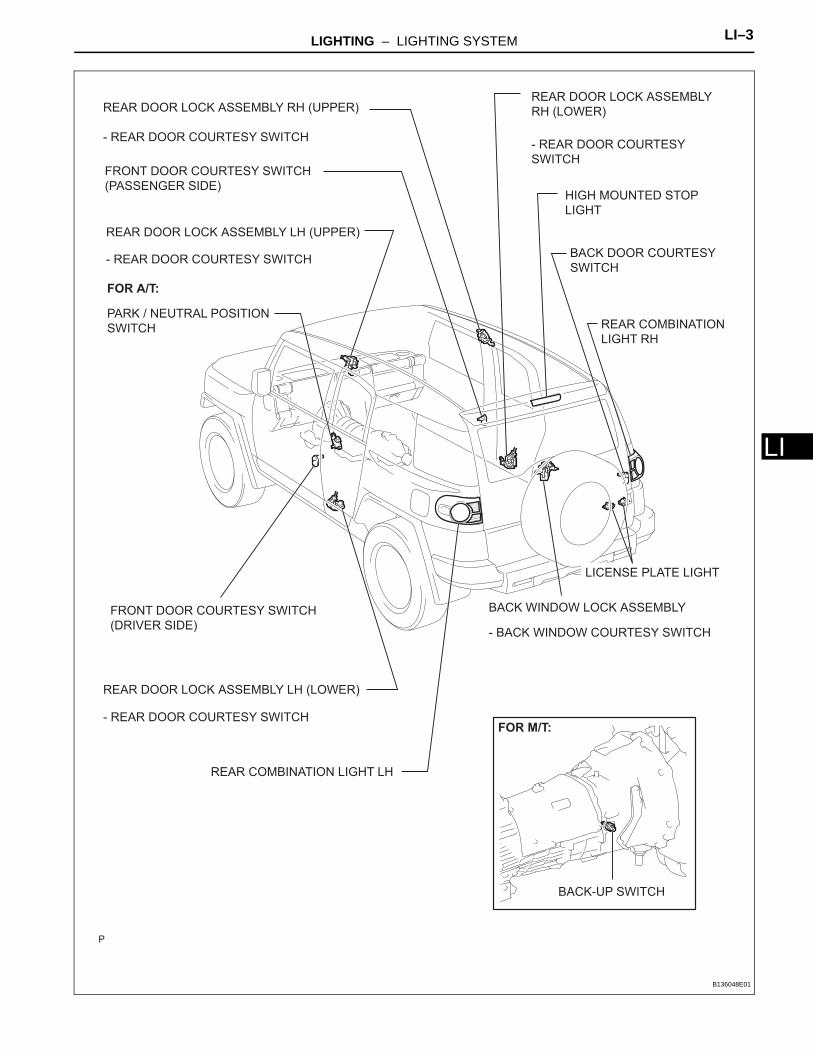
LBACK DOOR COURTESY
SWITCH
FRONT DOOR COURTESY SWITCH
(DRIVER SIDE)
FRONT DOOR COURTESY SWITCH
(PASSENGER SIDE)
- REAR DOOR COURTESY SWITCH
- REAR DOOR COURTESY SWITCH
- REAR DOOR COURTESY SWITCH- REAR DOOR COURTESY
SWITCH
REAR DOOR LOCK ASSEMBLY LH (LOWER)
BACK-UP SWITCH
- BACK WINDOW COURTESY SWITCH
REAR COMBINATION LIGHT LH
REAR COMBINATION
LIGHT RH
LICENSE PLATE LIGHT
PARK / NEUTRAL POSITION
SWITCH
REAR DOOR LOCK ASSEMBLY LH (UPPER)
REAR DOOR LOCK ASSEMBLY
RH (LOWER)
HIGH MOUNTED STOP
LIGHT
REAR DOOR LOCK ASSEMBLY RH (UPPER)
BACK WINDOW LOCK ASSEMBLY
FOR M/T:
FOR A/T:
B136048E01
LI–4 LIGHTING – LIGHTING SYSTEM
LI
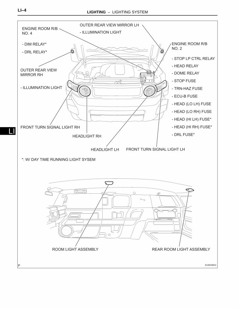
REAR ROOM LIGHT ASSEMBLYROOM LIGHT ASSEMBLY
OUTER REAR VIEW MIRROR LH
OUTER REAR VIEW
MIRROR RH
HEADLIGHT LH
ENGINE ROOM R/B
NO. 2
ENGINE ROOM R/B
NO. 4
- ILLUMINATION LIGHT
- ILLUMINATION LIGHT
- DRL RELAY*
- STOP LP CTRL RELAY
- DOME RELAY
- STOP FUSE
- TRN-HAZ FUSE
- ECU-B FUSE
- HEAD (LO LH) FUSE
- HEAD (LO RH) FUSE
- HEAD (HI LH) FUSE*
- HEAD (HI RH) FUSE*
- DRL FUSE*
*: W/ DAY TIME RUNNING LIGHT SYSEM
FRONT TURN SIGNAL LIGHT LH
FRONT TURN SIGNAL LIGHT RH
HEADLIGHT RH
- DIM RELAY*
- HEAD RELAY
B136049E01
LIGHTING – LIGHTING SYSTEM LI–5
I
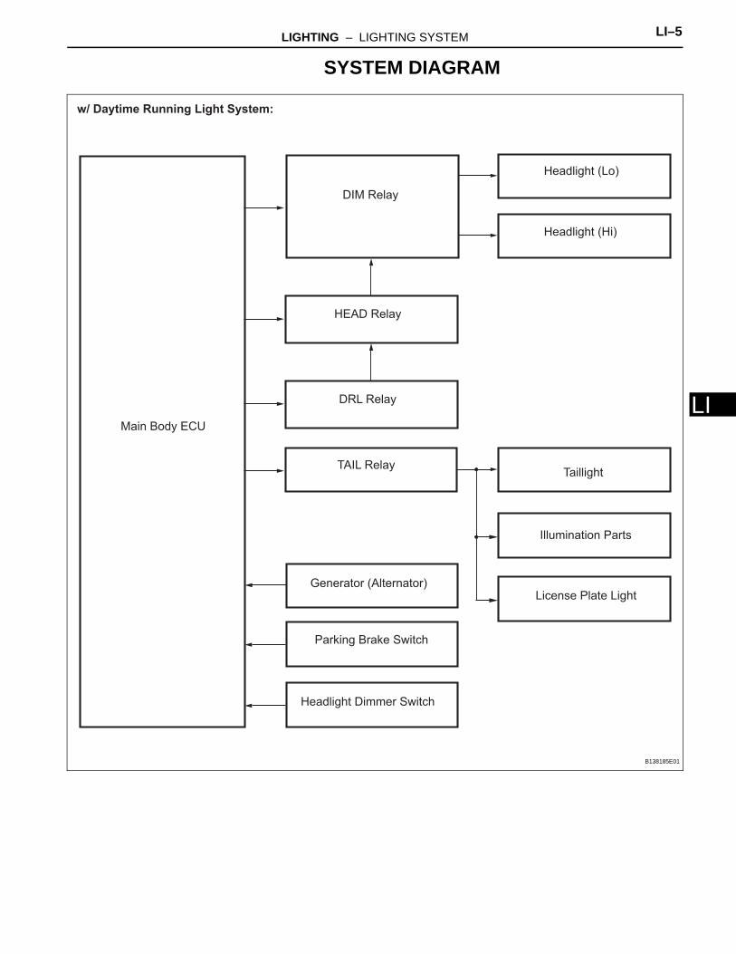
LSYSTEM DIAGRAM
Headlight Dimmer Switch
Generator (Alternator)
TAIL Relay
DIM Relay
HEAD Relay
DRL Relay
Taillight
Illumination Parts
License Plate Light
Headlight (Hi)
Headlight (Lo)
Parking Brake Switch
w/ Daytime Running Light System:
Main Body ECU
B138185E01
LI–6 LIGHTING – LIGHTING SYSTEM
LI
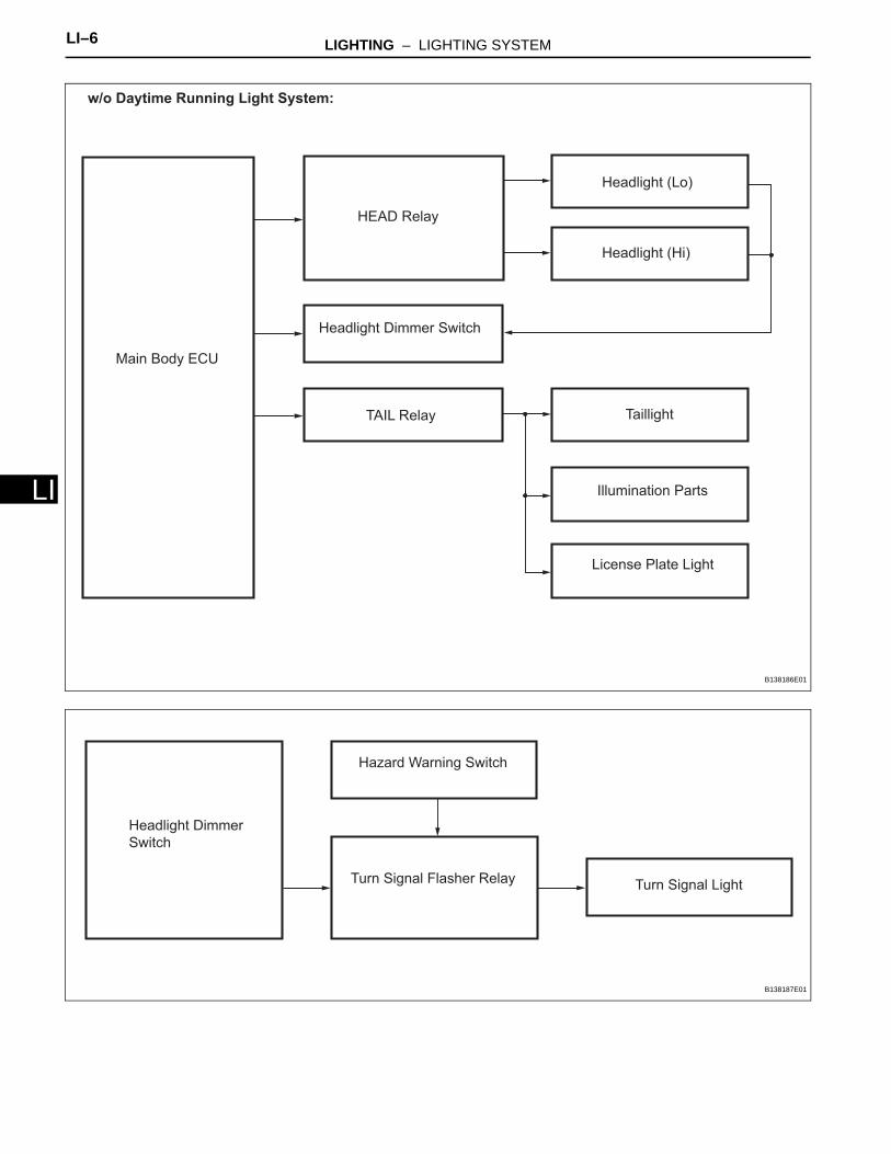
Headlight Dimmer Switch
HEAD Relay
TAIL Relay Taillight
Illumination Parts
License Plate Light
Headlight (Hi)
Headlight (Lo)
w/o Daytime Running Light System:
Main Body ECU
B138186E01
Hazard Warning Switch
Turn Signal Flasher Relay Turn Signal Light
Headlight Dimmer
Switch
B138187E01

LIGHTING – LIGHTING SYSTEM LI–7
I
LStop LightStop Light Switch
High Mounted Stop Light
Stop Light Control Relay
B138188E01
Park/ Neutral Position Switch*1 Back-up Light
Back-up Light Switch*2
*2: M/T
*1: A/T
From Battery
B138189E01
LI–8 LIGHTING – LIGHTING SYSTEM
LI
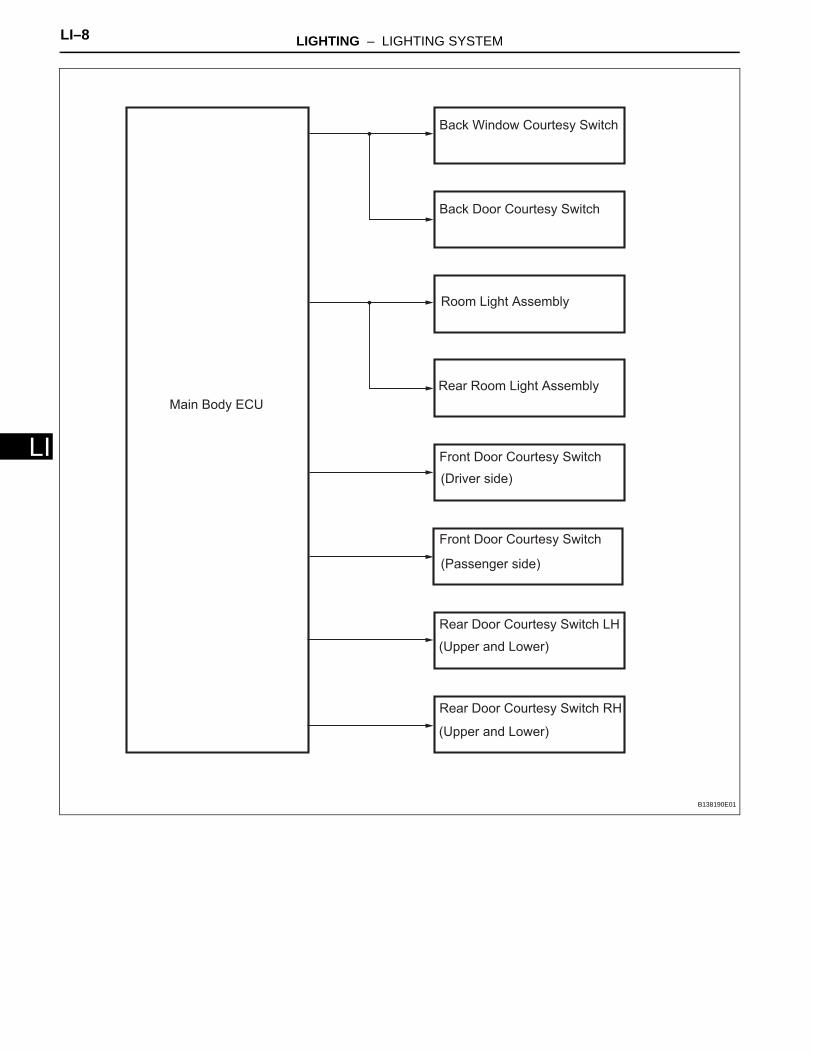
Front Door Courtesy SwitchFront Door Courtesy Switch
Rear Door Courtesy Switch LH
Rear Door Courtesy Switch RH
Back Window Courtesy Switch
Back Door Courtesy Switch
(Driver side)
(Passenger side)
(Upper and Lower)
(Upper and Lower)
Room Light Assembly
Rear Room Light Assembly
Main Body ECU
B138190E01
LIGHTING – LIGHTING SYSTEM LI–9
I
LSYSTEM DESCRIPTION1. LIGHTING SYSTEM
(a) Illumination control system (Illuminated entry system):When the doors are unlocked through a key or transmitter operation, or when a door is opened or closed, the illuminated entry system turns on the room light assembly.(1) The main body ECU receives the following
signal (A).• Door courtesy switch signal• Door detection switch signal• Ignition switch signal
(2) The main body ECU controls the following signal based on the signals listed in A.• Illumination operation signal
(3) The main body ECU controls the on/off and fade-in/fade-out operation of the following parts.• Room light assembly
(b) Battery saver system:When the ignition switch is turned off and the any of the doors is open continuously for 30 minutes, the main body ECU turns the illumination operation signal off. As a result, the room light assembly, taillights, and the headlights turn off.(1) The main body ECU receives the following
signals (B).• Door courtesy switch signal• Ignition switch signal
(2) The main body ECU controls the following signal based on the signals listed in B (C).• Illumination operation signal
(3) The main body ECU controls the illumination period of the following parts based on the signals listed in C.• Room light assembly• Headlight (Low)• Position light (Front and Rear)
(c) Manual light control system:This system functions when lights such as the headlights and taillights are illuminated through manual operation of the light control switch.(1) The main body ECU receives the following
signals (D).• Light control switch signal• Headlight dimmer switch signal
(2) The main body ECU controls the following signals based on the signals listed in D (E).• HEAD relay operation signal• TAIL relay operation signal• Running light relay assembly operation signal
LI–10 LIGHTING – LIGHTING SYSTEM
LI
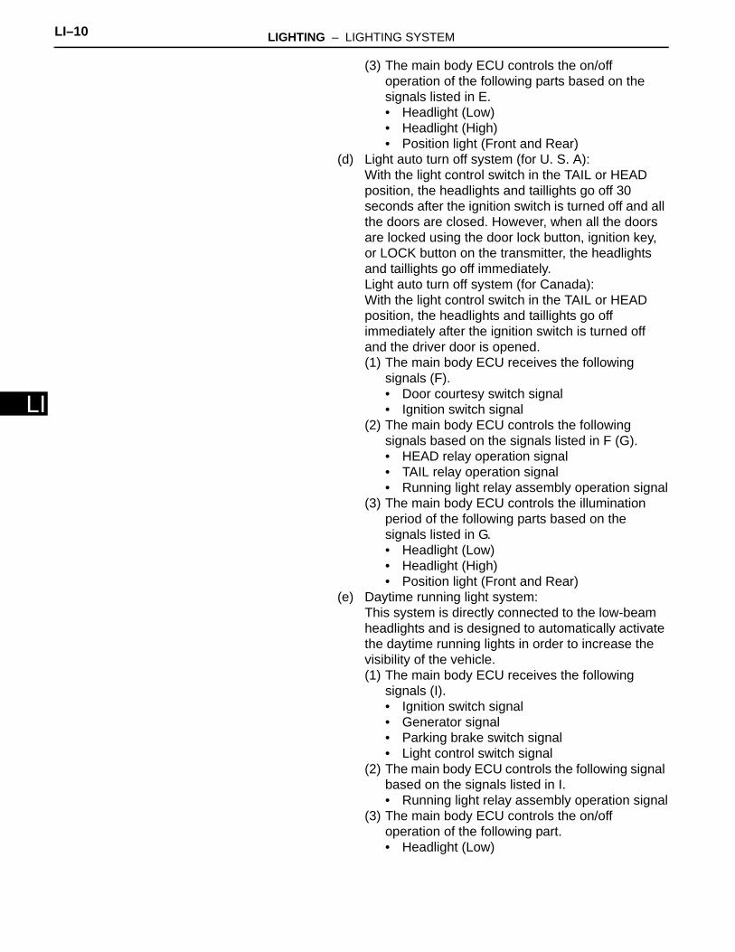
(3) The main body ECU controls the on/off operation of the following parts based on the signals listed in E.• Headlight (Low)• Headlight (High)• Position light (Front and Rear)
(d) Light auto turn off system (for U. S. A):With the light control switch in the TAIL or HEAD position, the headlights and taillights go off 30 seconds after the ignition switch is turned off and all the doors are closed. However, when all the doors are locked using the door lock button, ignition key, or LOCK button on the transmitter, the headlights and taillights go off immediately.Light auto turn off system (for Canada):With the light control switch in the TAIL or HEAD position, the headlights and taillights go off immediately after the ignition switch is turned off and the driver door is opened.(1) The main body ECU receives the following
signals (F).• Door courtesy switch signal• Ignition switch signal
(2) The main body ECU controls the following signals based on the signals listed in F (G).• HEAD relay operation signal• TAIL relay operation signal• Running light relay assembly operation signal
(3) The main body ECU controls the illumination period of the following parts based on the signals listed in G.• Headlight (Low)• Headlight (High)• Position light (Front and Rear)
(e) Daytime running light system:This system is directly connected to the low-beam headlights and is designed to automatically activate the daytime running lights in order to increase the visibility of the vehicle.(1) The main body ECU receives the following
signals (I).• Ignition switch signal• Generator signal• Parking brake switch signal• Light control switch signal
(2) The main body ECU controls the following signal based on the signals listed in I.• Running light relay assembly operation signal
(3) The main body ECU controls the on/off operation of the following part.• Headlight (Low)
LIGHTING – LIGHTING SYSTEM LI–11
I
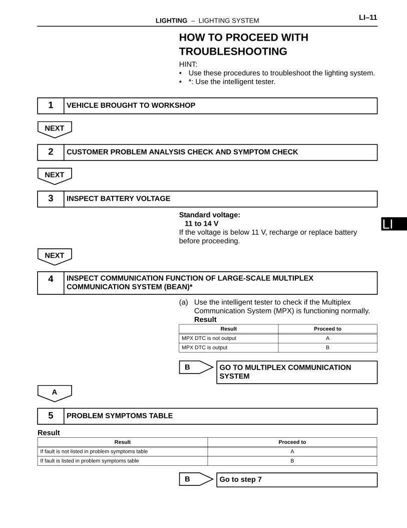
LHOW TO PROCEED WITH TROUBLESHOOTINGHINT:• Use these procedures to troubleshoot the lighting system.• *: Use the intelligent tester.
NEXT
NEXT
Standard voltage:11 to 14 V
If the voltage is below 11 V, recharge or replace battery before proceeding.
NEXT
(a) Use the intelligent tester to check if the Multiplex Communication System (MPX) is functioning normally.Result
B
A
Result
B
1 VEHICLE BROUGHT TO WORKSHOP
2 CUSTOMER PROBLEM ANALYSIS CHECK AND SYMPTOM CHECK
3 INSPECT BATTERY VOLTAGE
4 INSPECT COMMUNICATION FUNCTION OF LARGE-SCALE MULTIPLEX COMMUNICATION SYSTEM (BEAN)*
Result Proceed to
MPX DTC is not output A
MPX DTC is output B
GO TO MULTIPLEX COMMUNICATION SYSTEM
5 PROBLEM SYMPTOMS TABLE
Result Proceed to
If fault is not listed in problem symptoms table A
If fault is listed in problem symptoms table B
Go to step 7
LI–12 LIGHTING – LIGHTING SYSTEM
LI
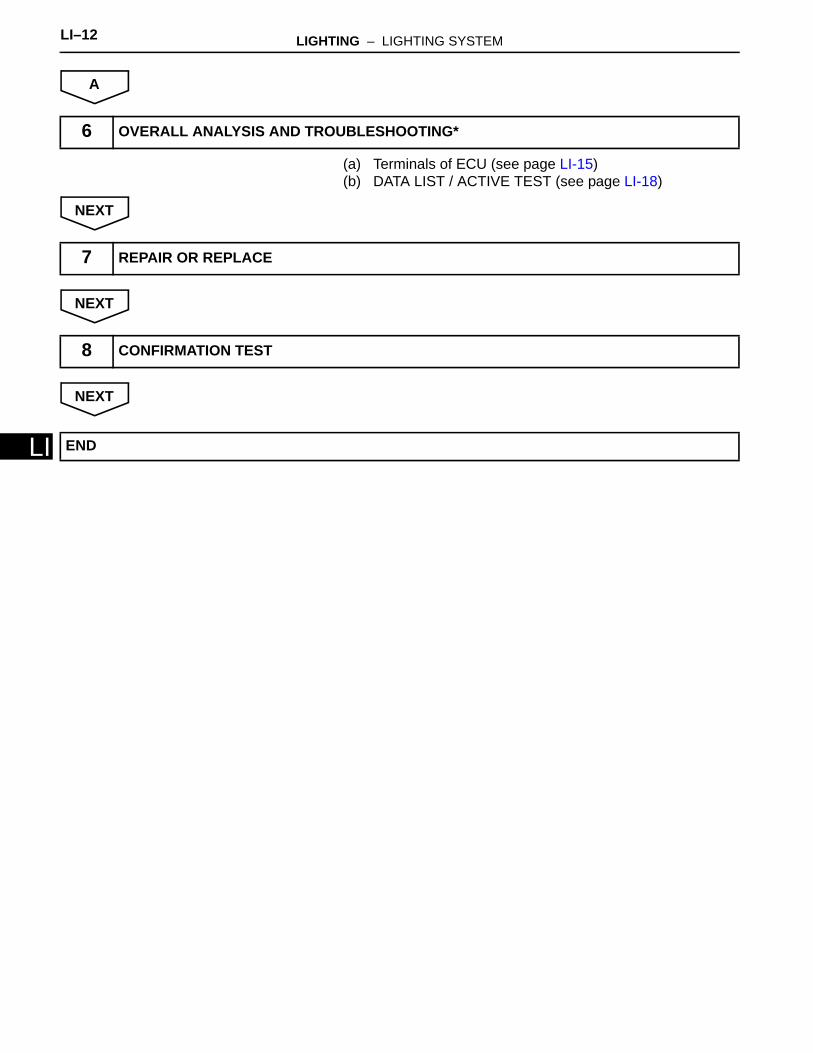
A
(a) Terminals of ECU (see page LI-15)(b) DATA LIST / ACTIVE TEST (see page LI-18)
NEXT
NEXT
NEXT
6 OVERALL ANALYSIS AND TROUBLESHOOTING*
7 REPAIR OR REPLACE
8 CONFIRMATION TEST
END
LIGHTING – LIGHTING SYSTEM LI–13
I
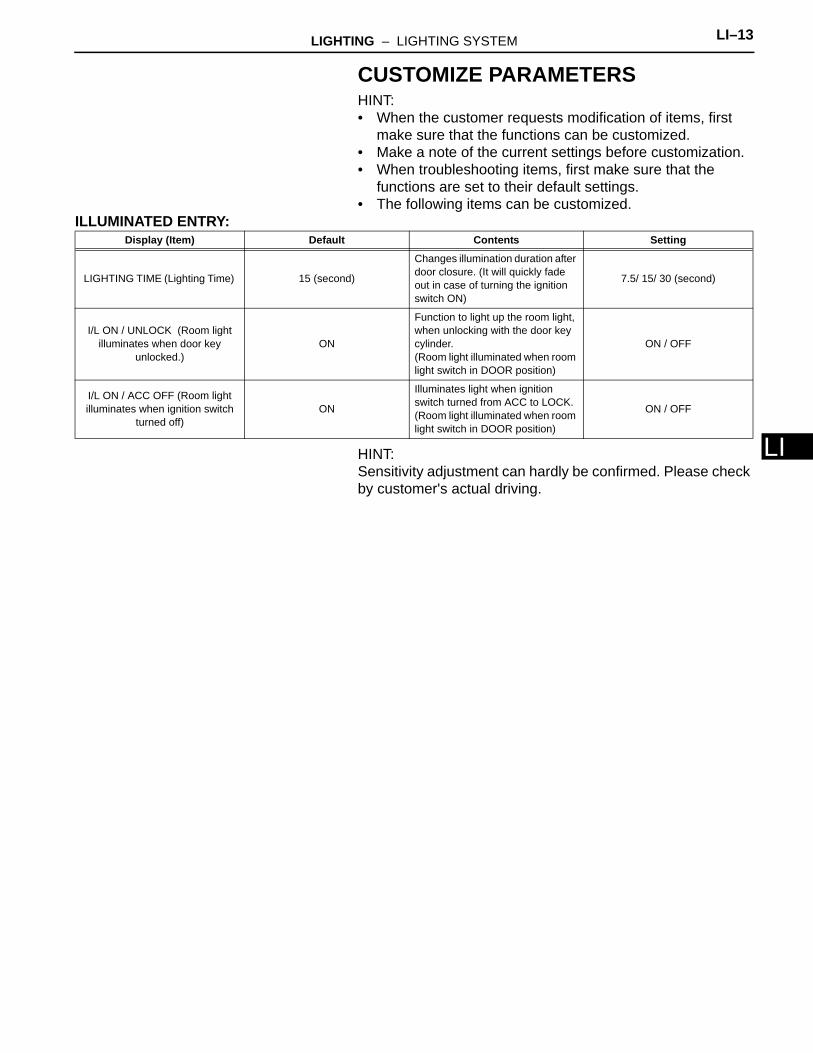
LCUSTOMIZE PARAMETERSHINT:• When the customer requests modification of items, first
make sure that the functions can be customized.• Make a note of the current settings before customization.• When troubleshooting items, first make sure that the
functions are set to their default settings.• The following items can be customized.
ILLUMINATED ENTRY:
HINT:Sensitivity adjustment can hardly be confirmed. Please check by customer's actual driving.
Display (Item) Default Contents Setting
LIGHTING TIME (Lighting Time) 15 (second)
Changes illumination duration after door closure. (It will quickly fade out in case of turning the ignition switch ON)
7.5/ 15/ 30 (second)
I/L ON / UNLOCK (Room light illuminates when door key
unlocked.)ON
Function to light up the room light, when unlocking with the door key cylinder.(Room light illuminated when room light switch in DOOR position)
ON / OFF
I/L ON / ACC OFF (Room light illuminates when ignition switch
turned off)ON
Illuminates light when ignition switch turned from ACC to LOCK.(Room light illuminated when room light switch in DOOR position)
ON / OFF
LI–14 LIGHTING – LIGHTING SYSTEM
LI
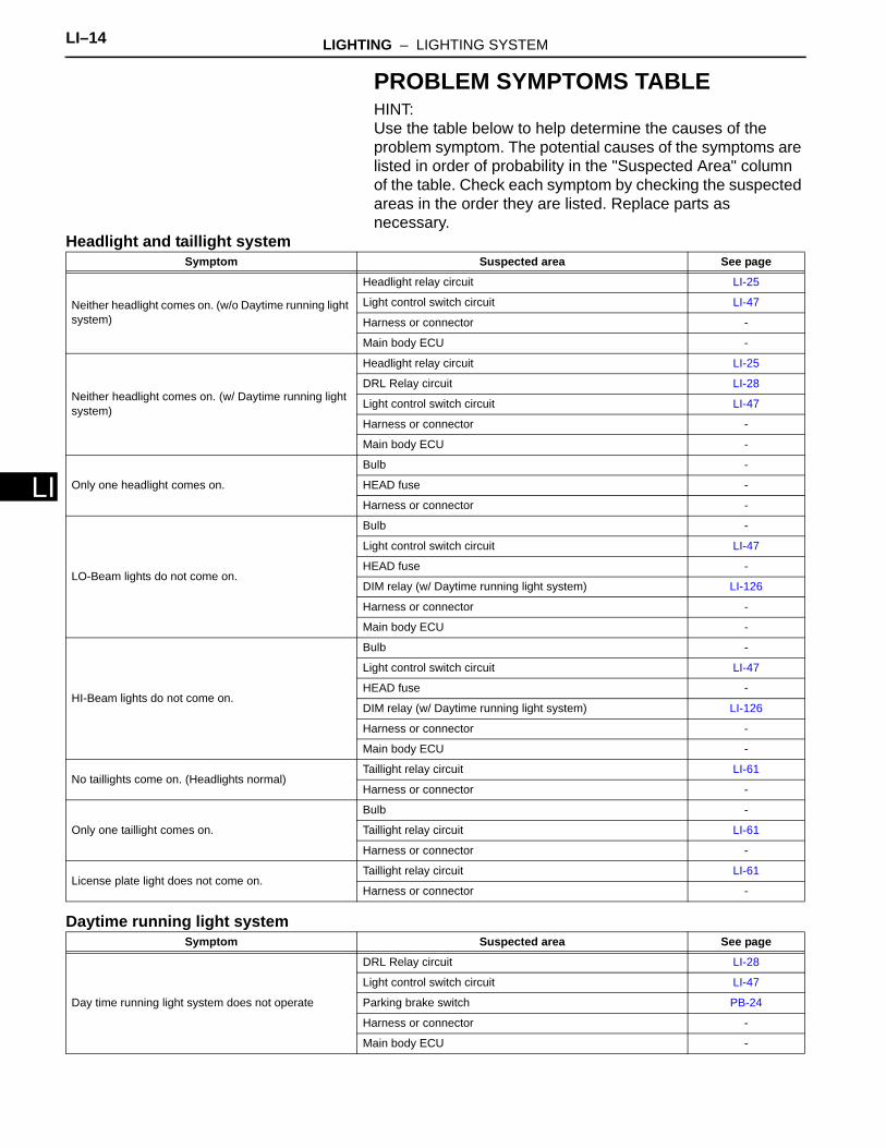
PROBLEM SYMPTOMS TABLEHINT:Use the table below to help determine the causes of the problem symptom. The potential causes of the symptoms are listed in order of probability in the "Suspected Area" column of the table. Check each symptom by checking the suspected areas in the order they are listed. Replace parts as necessary.
Headlight and taillight system
Daytime running light system
Symptom Suspected area See page
Neither headlight comes on. (w/o Daytime running light system)
Headlight relay circuit LI-25
Light control switch circuit LI-47
Harness or connector -
Main body ECU -
Neither headlight comes on. (w/ Daytime running light system)
Headlight relay circuit LI-25
DRL Relay circuit LI-28
Light control switch circuit LI-47
Harness or connector -
Main body ECU -
Only one headlight comes on.
Bulb -
HEAD fuse -
Harness or connector -
LO-Beam lights do not come on.
Bulb -
Light control switch circuit LI-47
HEAD fuse -
DIM relay (w/ Daytime running light system) LI-126
Harness or connector -
Main body ECU -
HI-Beam lights do not come on.
Bulb -
Light control switch circuit LI-47
HEAD fuse -
DIM relay (w/ Daytime running light system) LI-126
Harness or connector -
Main body ECU -
No taillights come on. (Headlights normal)Taillight relay circuit LI-61
Harness or connector -
Only one taillight comes on.
Bulb -
Taillight relay circuit LI-61
Harness or connector -
License plate light does not come on.Taillight relay circuit LI-61
Harness or connector -
Symptom Suspected area See page
Day time running light system does not operate
DRL Relay circuit LI-28
Light control switch circuit LI-47
Parking brake switch PB-24
Harness or connector -
Main body ECU -
LIGHTING – LIGHTING SYSTEM LI–15
I
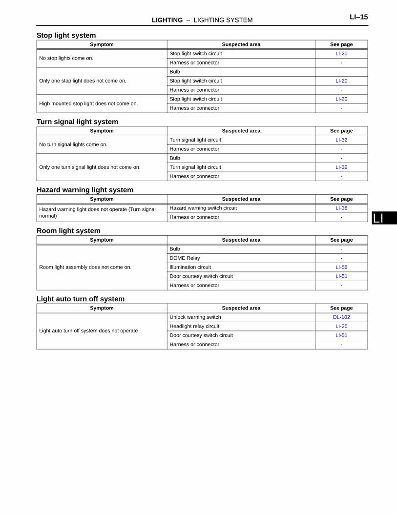
LStop light system
Turn signal light system
Hazard warning light system
Room light system
Light auto turn off system
Symptom Suspected area See page
No stop lights come on.Stop light switch circuit LI-20
Harness or connector -
Only one stop light does not come on.
Bulb -
Stop light switch circuit LI-20
Harness or connector -
High mounted stop light does not come on.Stop light switch circuit LI-20
Harness or connector -
Symptom Suspected area See page
No turn signal lights come on.Turn signal light circuit LI-32
Harness or connector -
Only one turn signal light does not come on.
Bulb -
Turn signal light circuit LI-32
Harness or connector -
Symptom Suspected area See page
Hazard warning light does not operate (Turn signal normal)
Hazard warning switch circuit LI-38
Harness or connector -
Symptom Suspected area See page
Room light assembly does not come on.
Bulb -
DOME Relay -
Illumination circuit LI-58
Door courtesy switch circuit LI-51
Harness or connector -
Symptom Suspected area See page
Light auto turn off system does not operate
Unlock warning switch DL-102
Headlight relay circuit LI-25
Door courtesy switch circuit LI-51
Harness or connector -
LI–16 LIGHTING – LIGHTING SYSTEM
LI
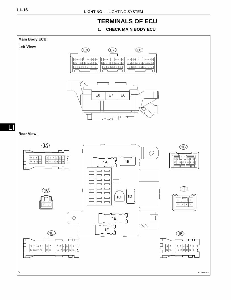
TERMINALS OF ECU1. CHECK MAIN BODY ECU
123456
111213141516
78910
17181920
123456
91011121314
78
1516
123456
1314
78
151617181920
910
2122
1112
2324
12345
678910111213
106 9565 844 733 622 511 4
16
3
15
2
14
1
13 2212
30291817 282726252423
2111 2010 199 181787171615141312111098 16151413
24
7
232221262524
1211
2023 1921201918 22
12
34561 2
E6
1A 1B
1D
1F1E
1C
E7E8
E6
1A 1B
1D
1F
1E
1C
E7E8
Main Body ECU:
Left View:
Rear View:
B136051E01
LIGHTING – LIGHTING SYSTEM LI–17
I
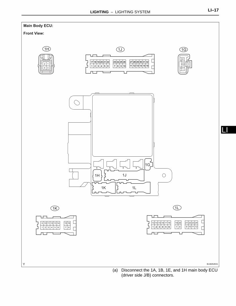
L(a) Disconnect the 1A, 1B, 1E, and 1H main body ECU (driver side J/B) connectors.
12
4 3
1 2 3 4 5 6 7 8
9 10 11 12 13 14 15 16
1
17
2
18
3
19
4
20
5
21
6
22
7
23
8
24
9
25
10
26
11
27
12
28
13
29
14
30
15
31
16
32
1
17
2
18
3
19
4
20
5
21
6
22
7
23
8
24
9
25
10
26
11
27
12
28
13
29
14
30
15
31
16
32
1
2
3
4
1
13
2
14
3
15
4
16
5
17
6
18 19 20
7 9
21
10
22
11
23
12
24
1 2 3 4 5 6 8
1G
1L1K
1J1H
1G
1H
1L
1J
1K
Main Body ECU:
Front View:
B136052E01
LI–18 LIGHTING – LIGHTING SYSTEM
LI
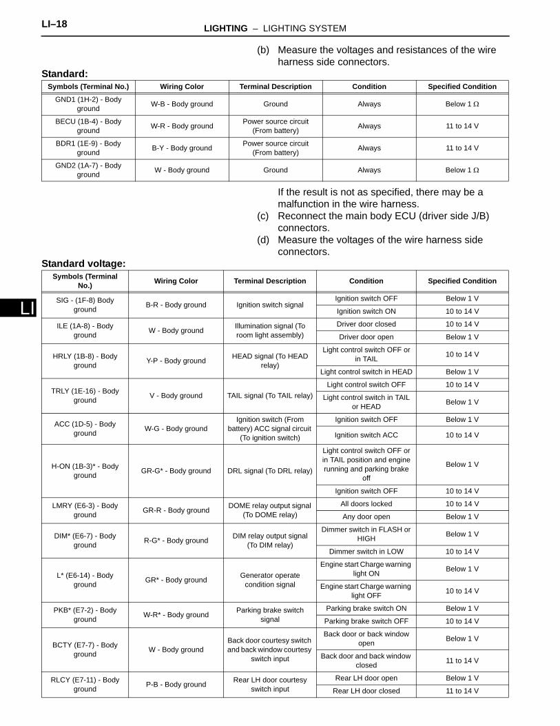
(b) Measure the voltages and resistances of the wire harness side connectors.
Standard:
If the result is not as specified, there may be a malfunction in the wire harness.
(c) Reconnect the main body ECU (driver side J/B) connectors.
(d) Measure the voltages of the wire harness side connectors.
Standard voltage:
Symbols (Terminal No.) Wiring Color Terminal Description Condition Specified Condition
GND1 (1H-2) - Body ground W-B - Body ground Ground Always Below 1 Ω
BECU (1B-4) - Body ground W-R - Body ground Power source circuit
(From battery) Always 11 to 14 V
BDR1 (1E-9) - Body ground B-Y - Body ground Power source circuit
(From battery) Always 11 to 14 V
GND2 (1A-7) - Body ground W - Body ground Ground Always Below 1 Ω
Symbols (Terminal No.) Wiring Color Terminal Description Condition Specified Condition
SIG - (1F-8) Body ground B-R - Body ground Ignition switch signal
Ignition switch OFF Below 1 V
Ignition switch ON 10 to 14 V
ILE (1A-8) - Body ground W - Body ground Illumination signal (To
room light assembly)Driver door closed 10 to 14 V
Driver door open Below 1 V
HRLY (1B-8) - Body ground Y-P - Body ground HEAD signal (To HEAD
relay)
Light control switch OFF or in TAIL 10 to 14 V
Light control switch in HEAD Below 1 V
TRLY (1E-16) - Body ground V - Body ground TAIL signal (To TAIL relay)
Light control switch OFF 10 to 14 V
Light control switch in TAIL or HEAD Below 1 V
ACC (1D-5) - Body ground W-G - Body ground
Ignition switch (From battery) ACC signal circuit
(To ignition switch)
Ignition switch OFF Below 1 V
Ignition switch ACC 10 to 14 V
H-ON (1B-3)* - Body ground GR-G* - Body ground DRL signal (To DRL relay)
Light control switch OFF or in TAIL position and engine running and parking brake
off
Below 1 V
Ignition switch OFF 10 to 14 V
LMRY (E6-3) - Body ground GR-R - Body ground DOME relay output signal
(To DOME relay)All doors locked 10 to 14 V
Any door open Below 1 V
DIM* (E6-7) - Body ground R-G* - Body ground DIM relay output signal
(To DIM relay)
Dimmer switch in FLASH or HIGH Below 1 V
Dimmer switch in LOW 10 to 14 V
L* (E6-14) - Body ground GR* - Body ground Generator operate
condition signal
Engine start Charge warning light ON Below 1 V
Engine start Charge warning light OFF 10 to 14 V
PKB* (E7-2) - Body ground W-R* - Body ground Parking brake switch
signalParking brake switch ON Below 1 V
Parking brake switch OFF 10 to 14 V
BCTY (E7-7) - Body ground W - Body ground
Back door courtesy switch and back window courtesy
switch input
Back door or back window open Below 1 V
Back door and back window closed 11 to 14 V
RLCY (E7-11) - Body ground P-B - Body ground Rear LH door courtesy
switch inputRear LH door open Below 1 V
Rear LH door closed 11 to 14 V
LIGHTING – LIGHTING SYSTEM LI–19
I
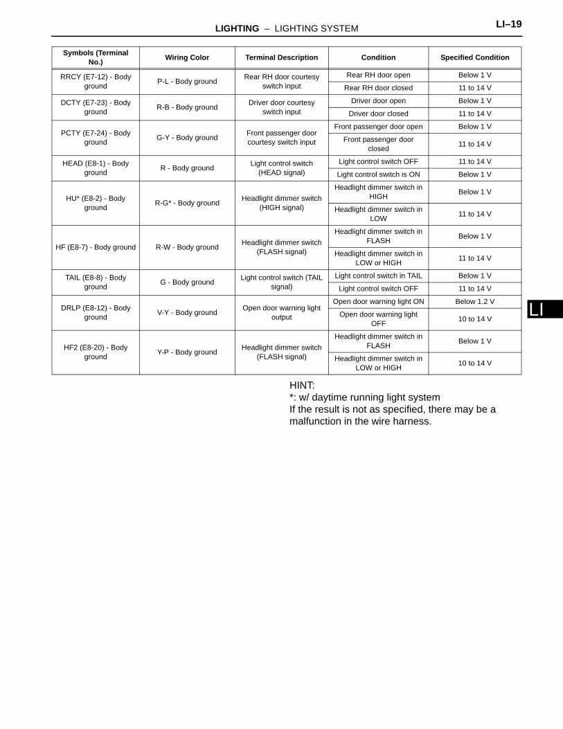
LHINT:*: w/ daytime running light systemIf the result is not as specified, there may be a malfunction in the wire harness.
RRCY (E7-12) - Body ground P-L - Body ground Rear RH door courtesy
switch inputRear RH door open Below 1 V
Rear RH door closed 11 to 14 V
DCTY (E7-23) - Body ground R-B - Body ground Driver door courtesy
switch inputDriver door open Below 1 V
Driver door closed 11 to 14 V
PCTY (E7-24) - Body ground G-Y - Body ground Front passenger door
courtesy switch input
Front passenger door open Below 1 V
Front passenger door closed 11 to 14 V
HEAD (E8-1) - Body ground R - Body ground Light control switch
(HEAD signal)Light control switch OFF 11 to 14 V
Light control switch is ON Below 1 V
HU* (E8-2) - Body ground R-G* - Body ground Headlight dimmer switch
(HIGH signal)
Headlight dimmer switch in HIGH Below 1 V
Headlight dimmer switch in LOW 11 to 14 V
HF (E8-7) - Body ground R-W - Body ground Headlight dimmer switch (FLASH signal)
Headlight dimmer switch in FLASH Below 1 V
Headlight dimmer switch in LOW or HIGH 11 to 14 V
TAIL (E8-8) - Body ground G - Body ground Light control switch (TAIL
signal)Light control switch in TAIL Below 1 V
Light control switch OFF 11 to 14 V
DRLP (E8-12) - Body ground V-Y - Body ground Open door warning light
output
Open door warning light ON Below 1.2 V
Open door warning light OFF 10 to 14 V
HF2 (E8-20) - Body ground Y-P - Body ground Headlight dimmer switch
(FLASH signal)
Headlight dimmer switch in FLASH Below 1 V
Headlight dimmer switch in LOW or HIGH 10 to 14 V
Symbols (Terminal No.) Wiring Color Terminal Description Condition Specified Condition
LI–20 LIGHTING – LIGHTING SYSTEM
LI
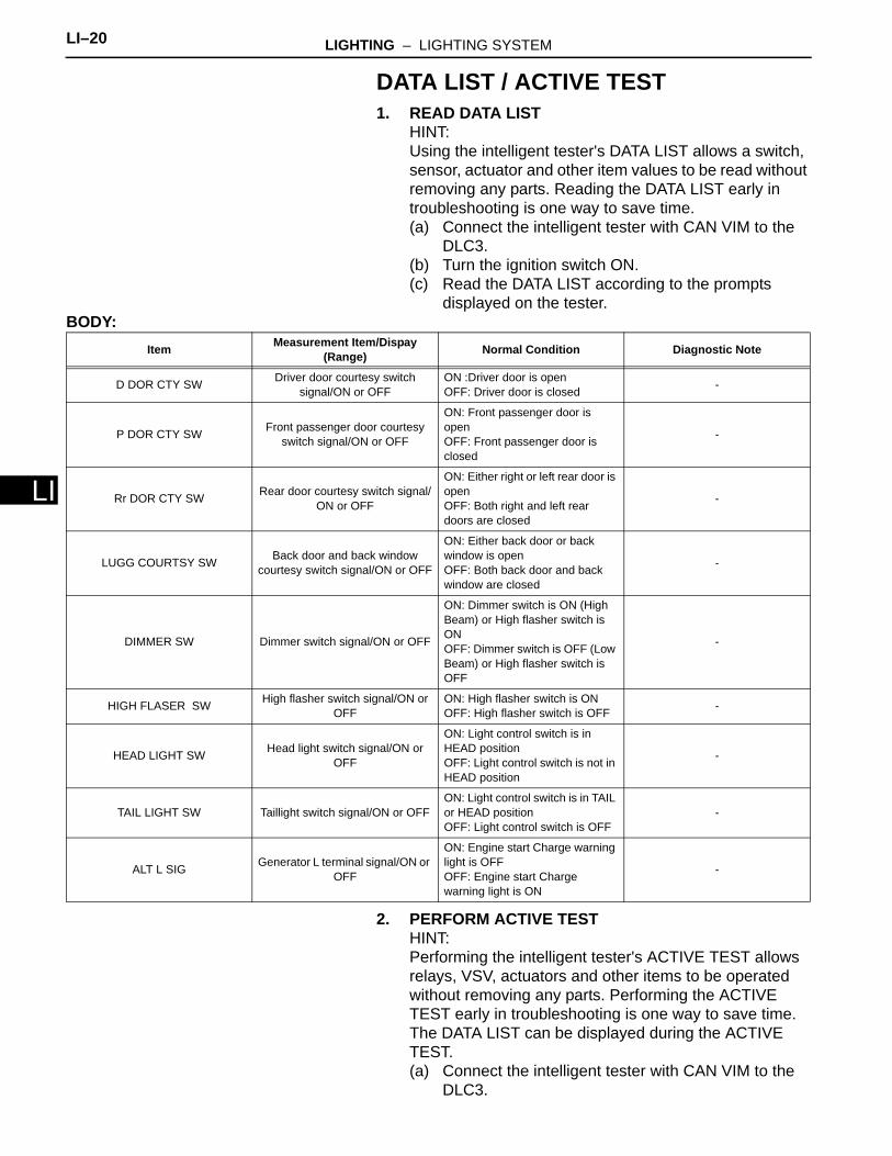
DATA LIST / ACTIVE TEST1. READ DATA LIST
HINT:Using the intelligent tester's DATA LIST allows a switch, sensor, actuator and other item values to be read without removing any parts. Reading the DATA LIST early in troubleshooting is one way to save time.(a) Connect the intelligent tester with CAN VIM to the
DLC3.(b) Turn the ignition switch ON.(c) Read the DATA LIST according to the prompts
displayed on the tester.BODY:
2. PERFORM ACTIVE TESTHINT:Performing the intelligent tester's ACTIVE TEST allows relays, VSV, actuators and other items to be operated without removing any parts. Performing the ACTIVE TEST early in troubleshooting is one way to save time. The DATA LIST can be displayed during the ACTIVE TEST.(a) Connect the intelligent tester with CAN VIM to the
DLC3.
Item Measurement Item/Dispay (Range) Normal Condition Diagnostic Note
D DOR CTY SW Driver door courtesy switch signal/ON or OFF
ON :Driver door is openOFF: Driver door is closed -
P DOR CTY SW Front passenger door courtesy switch signal/ON or OFF
ON: Front passenger door is openOFF: Front passenger door is closed
-
Rr DOR CTY SW Rear door courtesy switch signal/ON or OFF
ON: Either right or left rear door is openOFF: Both right and left rear doors are closed
-
LUGG COURTSY SW Back door and back window courtesy switch signal/ON or OFF
ON: Either back door or back window is openOFF: Both back door and back window are closed
-
DIMMER SW Dimmer switch signal/ON or OFF
ON: Dimmer switch is ON (High Beam) or High flasher switch is ONOFF: Dimmer switch is OFF (Low Beam) or High flasher switch is OFF
-
HIGH FLASER SW High flasher switch signal/ON or OFF
ON: High flasher switch is ONOFF: High flasher switch is OFF -
HEAD LIGHT SW Head light switch signal/ON or OFF
ON: Light control switch is in HEAD positionOFF: Light control switch is not in HEAD position
-
TAIL LIGHT SW Taillight switch signal/ON or OFFON: Light control switch is in TAIL or HEAD positionOFF: Light control switch is OFF
-
ALT L SIG Generator L terminal signal/ON or OFF
ON: Engine start Charge warning light is OFFOFF: Engine start Charge warning light is ON
-
LIGHTING – LIGHTING SYSTEM LI–21
I
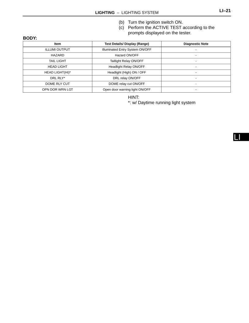
L(b) Turn the ignition switch ON.(c) Perform the ACTIVE TEST according to the
prompts displayed on the tester.BODY:
HINT:*: w/ Daytime running light system
Item Test Details/ Display (Range) Diagnostic Note
ILLUMI OUTPUT Illuminated Entry System ON/OFF -
HAZARD Hazard ON/OFF -
TAIL LIGHT Taillight Relay ON/OFF -
HEAD LIGHT Headlight Relay ON/OFF -
HEAD LIGHT(HI)* Headlight (High) ON / OFF -
DRL RLY* DRL relay ON/OFF -
DOME RLY CUT DOME relay cut ON/OFF -
OPN DOR WRN LGT Open door warning light ON/OFF -
LI–22 LIGHTING – LIGHTING SYSTEM
LI
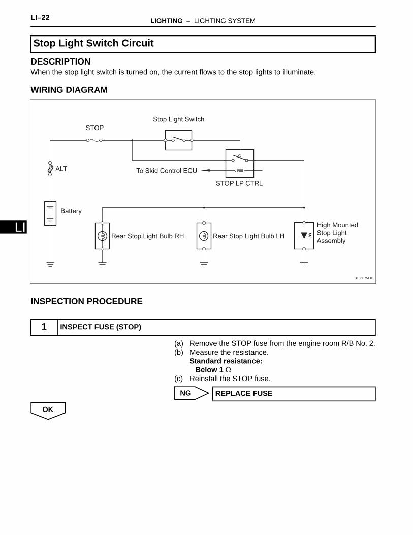
DESCRIPTIONWhen the stop light switch is turned on, the current flows to the stop lights to illuminate.
WIRING DIAGRAM
INSPECTION PROCEDURE
(a) Remove the STOP fuse from the engine room R/B No. 2.(b) Measure the resistance.
Standard resistance:Below 1 Ω
(c) Reinstall the STOP fuse.
NG
OK
Stop Light Switch Circuit
1 INSPECT FUSE (STOP)
Stop Light Switch
To Skid Control ECU
STOP LP CTRL
STOP
Rear Stop Light Bulb RH Rear Stop Light Bulb LH
High Mounted
Stop Light
Assembly
Battery
ALT
B136075E01
REPLACE FUSE
LIGHTING – LIGHTING SYSTEM LI–23
I
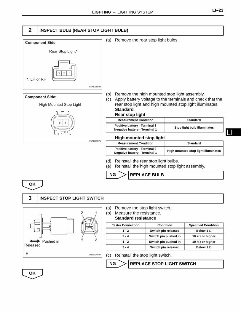
L(a) Remove the rear stop light bulbs.
(b) Remove the high mounted stop light assembly.(c) Apply battery voltage to the terminals and check that the
rear stop light and high mounted stop light illuminates.StandardRear stop light
High mounted stop light
(d) Reinstall the rear stop light bulbs.(e) Reinstall the high mounted stop light assembly.
NG
OK
(a) Remove the stop light switch.(b) Measure the resistance.
Standard resistance
(c) Reinstall the stop light switch.
NG
OK
2 INSPECT BULB (REAR STOP LIGHT BULB)
123
Component Side:
*: LH or RH
Rear Stop Light*
B141038E03
12
Component Side:
High Mounted Stop Light
B141590E01
Measurement Condition Standard
Positive battery - Terminal 3Negative battery - Terminal 1 Stop light bulb illuminates
Measurement Condition Standard
Positive battery - Terminal 2Negative battery - Terminal 1 High mounted stop light illuminates
REPLACE BULB
3 INSPECT STOP LIGHT SWITCH
12
34Pushed in
Released
B113724E04
Tester Connection Condition Specified Condition
1 - 2 Switch pin released Below 1 Ω
3 - 4 Switch pin pushed in 10 kΩ or higher
1 - 2 Switch pin pushed in 10 kΩ or higher
3 - 4 Switch pin released Below 1 Ω
REPLACE STOP LIGHT SWITCH

LI–24 LIGHTING – LIGHTING SYSTEM
LI
(a) Remove the STOP LP CTRL relay from the engine room R/B No. 2
(b) Measure the resistance.Standard resistance
(c) Reinstall the STOP LP CTRL relay.
NG
OK
(a) Disconnect the A3 stop light switch connector.(b) Measure the voltage.
Standard voltage
(c) Reconnect the stop light switch connector.
NG
OK
4 INSPECT STOP LP CTRL RELAY
Stop Light Control
Relay
C083933E02
Tester Connection Specified Condition
3 - 4 Below 1 Ω
3 - 5 10 kΩ or higher
3 - 410 kΩ or higher
(When battery voltage is applied between terminals 1 and 2)
3 - 5Below 1 Ω
(When battery voltage is applied between terminals 1 and 2)
REPLACE STOP LP CTRL RELAY
5 CHECK HARNESS AND CONNECTOR (FUSE - STOP LIGHT SWITCH)
1 2
3 4
Wire Haeness Side:
Stop Light Switch Connector
Front View
A3
B124046E08
Tester Connection Condition Specified Condition
A3-2 - Body ground Always 11 to 14 V
REPAIR OR REPLACE HARNESS OR CONNECTOR
LIGHTING – LIGHTING SYSTEM LI–25
I
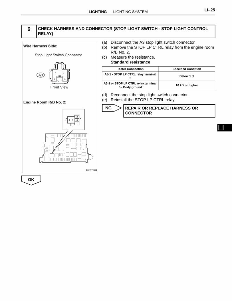
L(a) Disconnect the A3 stop light switch connector.(b) Remove the STOP LP CTRL relay from the engine room
R/B No. 2.(c) Measure the resistance.
Standard resistance
(d) Reconnect the stop light switch connector.(e) Reinstall the STOP LP CTRL relay.
NG
OK
6 CHECK HARNESS AND CONNECTOR (STOP LIGHT SWITCH - STOP LIGHT CONTROL RELAY)
Wire Harness Side:
Stop Light Switch Connector
Front View
A3
Engine Room R/B No. 2:
B136076E01
Tester Connection Specified Condition
A3-1 - STOP LP CTRL relay terminal 5 Below 1 Ω
A3-1 or STOP LP CTRL relay terminal 5 - Body ground 10 kΩ or higher
REPAIR OR REPLACE HARNESS OR CONNECTOR
LI–26 LIGHTING – LIGHTING SYSTEM
LI
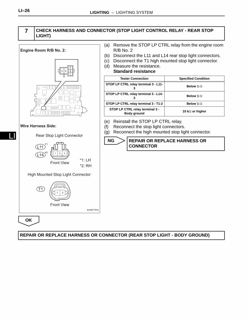
(a) Remove the STOP LP CTRL relay from the engine room R/B No. 2
(b) Disconnect the L11 and L14 rear stop light connectors.(c) Disconnect the T1 high mounted stop light connector.(d) Measure the resistance.
Standard resistance
(e) Reinstall the STOP LP CTRL relay.(f) Reconnect the stop light connectors.(g) Reconnect the high mounted stop light connector.
NG
OK
7 CHECK HARNESS AND CONNECTOR (STOP LIGHT CONTROL RELAY - REAR STOP LIGHT)
1 2
1 32
Wire Harness Side:
Rear Stop Light Connector
*1: LH
*2: RH
High Mounted Stop Light Connector
Front View
Front View
Engine Room R/B No. 2:
L11
L14
T1
*1
*2
B136077E01
Tester Connection Specified Condition
STOP LP CTRL relay terminal 3 - L11-3 Below 1 Ω
STOP LP CTRL relay terminal 3 - L14-3 Below 1 Ω
STOP LP CTRL relay terminal 3 - T1-2 Below 1 Ω
STOP LP CTRL relay terminal 3 - Body ground 10 kΩ or higher
REPAIR OR REPLACE HARNESS OR CONNECTOR
REPAIR OR REPLACE HARNESS OR CONNECTOR (REAR STOP LIGHT - BODY GROUND)

LIGHTING – LIGHTING SYSTEM LI–27
I
LDESCRIPTIONThe headlight dimmer switch sends a signal to the main body ECU.
WIRING DIAGRAM
INSPECTION PROCEDURE
(a) Connect the intelligent tester with CAN VIM to the DLC3. (b) Turn the ignition switch ON. (c) Turn the intelligent tester main switch on.(d) Select the item below in the ACTIVE TEST and then
check the relay operation. BODY
Headlight Relay Circuit
1 PERFORM ACTIVE TEST BY INTELLIGENT TESTER (HEAD LIGHT)
HEAD
To
BatteryHEAD (LO LH)
HEAD (LO RH)
To Headlight LH
To Headlight RH
HRLY
w/o Daytime running light system:
Main Body ECU
E111804E04
HEAD
To
Battery
To DIM Relay
HRLY
w/ Daytime running light system:
Main Body ECU
B136080E01
Item Test Details Diagnostic Note
HEAD LIGHT Headlight relay ON / OFF -
LI–28 LIGHTING – LIGHTING SYSTEM
LI
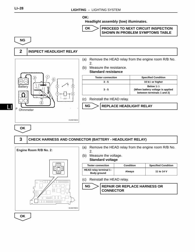
OK:Headlight assembly (low) illuminates.
OK
NG
(a) Remove the HEAD relay from the engine room R/B No. 2.
(b) Measure the resistance.Standard resistance
(c) Reinstall the HEAD relay.
NG
OK
(a) Remove the HEAD relay from the engine room R/B No. 2.
(b) Measure the voltage.Standard voltage
(c) Reinstall the HEAD relay.
NG
OK
PROCEED TO NEXT CIRCUIT INSPECTION SHOWN IN PROBLEM SYMPTOMS TABLE
2 INSPECT HEADLIGHT RELAY
Battery
Ohmmeter
E109076E03
Tester connection Specified Condition
3 - 5 10 kΩ or higher
3 - 5Below 1 Ω
(When battery voltage is applied between terminals 1 and 2)
REPLACE HEADLIGHT RELAY
3 CHECK HARNESS AND CONNECTOR (BATTERY - HEADLIGHT RELAY)
Engine Room R/B No. 2:
B136078E01
Tester connection Condition Specified Condition
HEAD relay terminal 1 - Body ground Always 11 to 14 V
REPAIR OR REPLACE HARNESS OR CONNECTOR
LIGHTING – LIGHTING SYSTEM LI–29
I
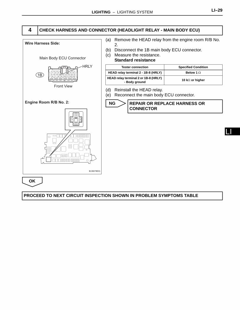
L(a) Remove the HEAD relay from the engine room R/B No. 2.
(b) Disconnect the 1B main body ECU connector.(c) Measure the resistance.
Standard resistance
(d) Reinstall the HEAD relay.(e) Reconnect the main body ECU connector.
NG
OK
4 CHECK HARNESS AND CONNECTOR (HEADLIGHT RELAY - MAIN BODY ECU)
1 2 3 4 5
6 7 8 9 10 11 12 13
Engine Room R/B No. 2:
Wire Harness Side:
Front View
HRLY
1B
Main Body ECU Connector
B136079E01
Tester connection Specified Condition
HEAD relay terminal 2 - 1B-8 (HRLY) Below 1 Ω
HEAD relay terminal 2 or 1B-8 (HRLY) - Body ground 10 kΩ or higher
REPAIR OR REPLACE HARNESS OR CONNECTOR
PROCEED TO NEXT CIRCUIT INSPECTION SHOWN IN PROBLEM SYMPTOMS TABLE
LI–30 LIGHTING – LIGHTING SYSTEM
LI
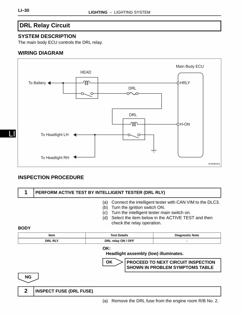
SYSTEM DESCRIPTIONThe main body ECU controls the DRL relay.
WIRING DIAGRAM
INSPECTION PROCEDURE
(a) Connect the intelligent tester with CAN VIM to the DLC3. (b) Turn the ignition switch ON. (c) Turn the intelligent tester main switch on.(d) Select the item below in the ACTIVE TEST and then
check the relay operation. BODY
OK:Headlight assembly (low) illuminates.
OK
NG
(a) Remove the DRL fuse from the engine room R/B No. 2.
DRL Relay Circuit
1 PERFORM ACTIVE TEST BY INTELLIGENT TESTER (DRL RLY)
HRLY
DRL
DRL
HEAD
To Headlight LH
To Headlight RH
To Battery
H-ON
Main Body ECU
B136081E01
Item Test Details Diagnostic Note
DRL RLY DRL relay ON / OFF -
PROCEED TO NEXT CIRCUIT INSPECTION SHOWN IN PROBLEM SYMPTOMS TABLE
2 INSPECT FUSE (DRL FUSE)
LIGHTING – LIGHTING SYSTEM LI–31
I
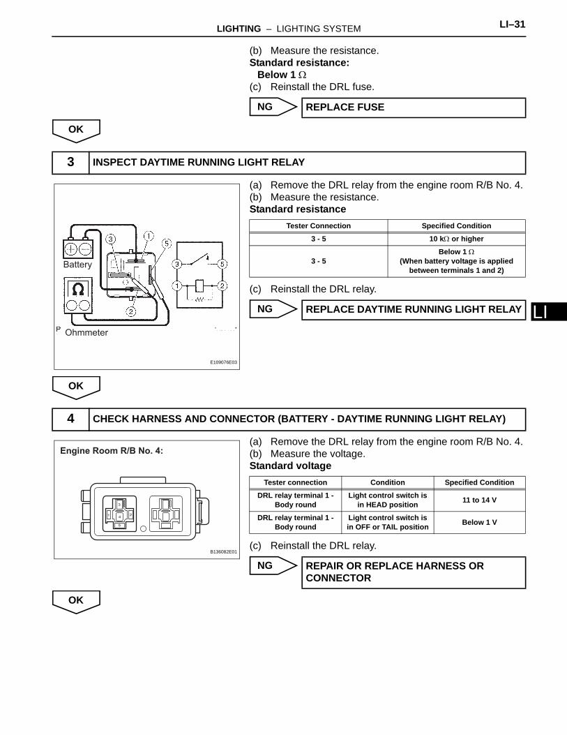
L(b) Measure the resistance.Standard resistance:
Below 1 Ω(c) Reinstall the DRL fuse.
NG
OK
(a) Remove the DRL relay from the engine room R/B No. 4.(b) Measure the resistance.Standard resistance
(c) Reinstall the DRL relay.
NG
OK
(a) Remove the DRL relay from the engine room R/B No. 4.(b) Measure the voltage.Standard voltage
(c) Reinstall the DRL relay.
NG
OK
REPLACE FUSE
3 INSPECT DAYTIME RUNNING LIGHT RELAY
Battery
Ohmmeter
E109076E03
Tester Connection Specified Condition
3 - 5 10 kΩ or higher
3 - 5Below 1 Ω
(When battery voltage is applied between terminals 1 and 2)
REPLACE DAYTIME RUNNING LIGHT RELAY
4 CHECK HARNESS AND CONNECTOR (BATTERY - DAYTIME RUNNING LIGHT RELAY)
Engine Room R/B No. 4:
B136082E01
Tester connection Condition Specified Condition
DRL relay terminal 1 - Body round
Light control switch is in HEAD position 11 to 14 V
DRL relay terminal 1 - Body round
Light control switch is in OFF or TAIL position Below 1 V
REPAIR OR REPLACE HARNESS OR CONNECTOR

LI–32 LIGHTING – LIGHTING SYSTEM
LI
(a) Remove the DRL relay from the engine room R/B No. 4.(b) Disconnect the 1B main body ECU connector.(c) Measure the resistance.Standard resistance
(d) Reinstall the DRL relay.(e) Reconnect the main body ECU connector.
NG
OK
(a) Remove the DRL relay from the engine room R/B No. 4.(b) Disconnect the A23 and A24 headlight connectors.(c) Measure the resistance.Standard resistance
(d) Reinstall the DRL relay.(e) Reconnect the headlight connectors.
NG
5 CHECK HARNESS AND CONNECTOR (DAYTIME RUNNING LIGHT RELAY - MAIN BODY ECU)
1 2 3 4 5
6 7 8 9 10 11 12 13
Front View
Wire Harness Side:
1B
Engine Room R/B No. 4:
Main Body ECU Connector
B136083E01
Tester Connection Specified Condition
DRL relay terminal 2 - 1B-3 (H-ON) Below 1 Ω
DRL relay terminal 2 or 1B-3 (H-ON) - Body ground 10 kΩ or higher
REPAIR OR REPLACE HARNESS OR CONNECTOR
6 CHECK HARNESS AND CONNECTOR (DAYTIME RUNNING LIGHT RELAY - HEADLIGHT, BODY GROUND)
Engine Room R/B No. 4:
Headlight Connector
Front View*1: LH
*2: RH
Wire Harness Side:
A23
A24
*1
*2
B136084E01
Tester Connection Specified Condition
DRL relay terminal 3 - A23-3 Below 1 Ω
DRL relay terminal 3 or A23-3 - Body ground 10 kΩ or higher
DRL relay terminal 3 - A24-3 Below 1 Ω
DRL relay terminal 3 or A24-3 - Body ground 10 kΩ or higher
DRL relay terminal 5 - Body ground Below 1 Ω
REPAIR OR REPLACE HARNESS OR CONNECTOR
LIGHTING – LIGHTING SYSTEM LI–33
I
LOK
PROCEED TO NEXT CIRCUIT INSPECTION SHOWN IN PROBLEM SYMPTOMS TABLE
LI–34 LIGHTING – LIGHTING SYSTEM
LI
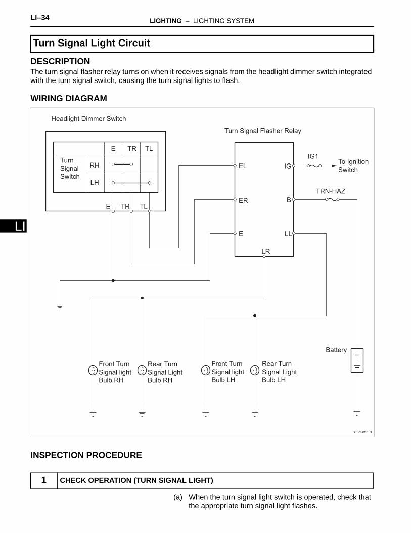
DESCRIPTIONThe turn signal flasher relay turns on when it receives signals from the headlight dimmer switch integrated with the turn signal switch, causing the turn signal lights to flash.
WIRING DIAGRAM
INSPECTION PROCEDURE
(a) When the turn signal light switch is operated, check that the appropriate turn signal light flashes.
Turn Signal Light Circuit
1 CHECK OPERATION (TURN SIGNAL LIGHT)
Headlight Dimmer Switch
Turn
Signal
Switch
RH
LH
E TLTR
E TLTR
Turn Signal Flasher Relay
E
ER
EL
B
IG
IG1
TRN-HAZ
LR
LL
Front Turn
Signal light
Bulb RH
Rear Turn
Signal Light
Bulb RH
Front Turn
Signal light
Bulb LH
Rear Turn
Signal Light
Bulb LH
Battery
To Ignition
Switch
B136085E01
LIGHTING – LIGHTING SYSTEM LI–35
I
LResult
B
C
A
(a) Remove the IG1 fuse from the main body ECU.(b) Remove the TRN-HAZ fuse from the engine room R/B
No.2.(c) Measure the resistance.
Standard resistance:Below 1 Ω
(d) Reinstall the IG1 and TRN-HAZ fuses.
NG
OK
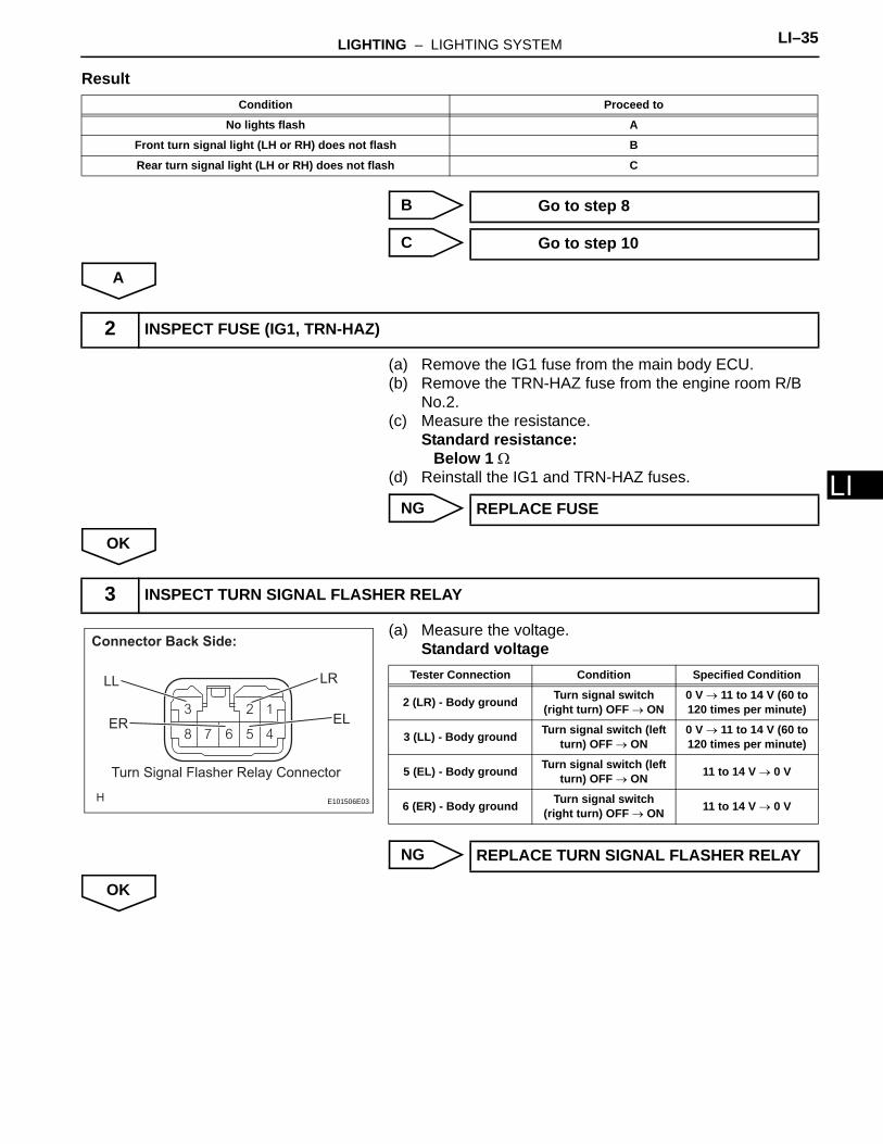
(a) Measure the voltage.Standard voltage
NG
OK
Condition Proceed to
No lights flash A
Front turn signal light (LH or RH) does not flash B
Rear turn signal light (LH or RH) does not flash C
Go to step 8
Go to step 10
2 INSPECT FUSE (IG1, TRN-HAZ)
REPLACE FUSE
3 INSPECT TURN SIGNAL FLASHER RELAY
Connector Back Side:
LRLL
Turn Signal Flasher Relay Connector
ELER
E101506E03
Tester Connection Condition Specified Condition
2 (LR) - Body ground Turn signal switch (right turn) OFF → ON
0 V → 11 to 14 V (60 to 120 times per minute)
3 (LL) - Body ground Turn signal switch (left turn) OFF → ON
0 V → 11 to 14 V (60 to 120 times per minute)
5 (EL) - Body ground Turn signal switch (left turn) OFF → ON 11 to 14 V → 0 V
6 (ER) - Body ground Turn signal switch (right turn) OFF → ON 11 to 14 V → 0 V
REPLACE TURN SIGNAL FLASHER RELAY
LI–36 LIGHTING – LIGHTING SYSTEM
LI
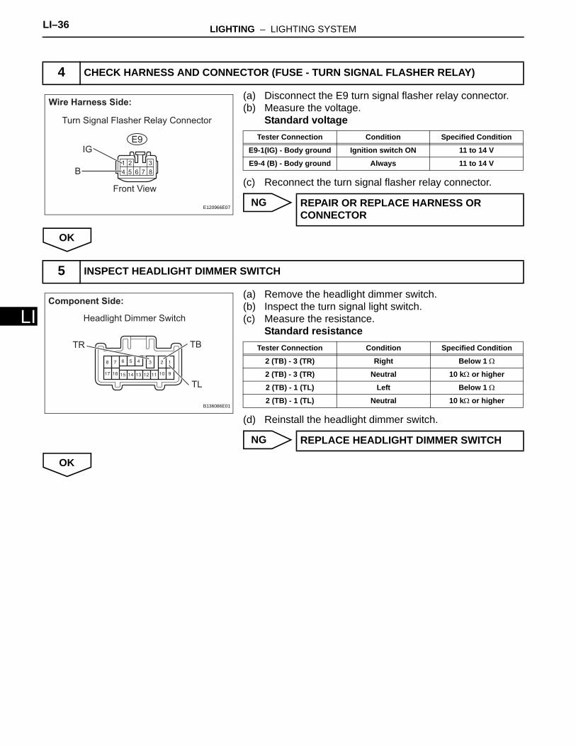
(a) Disconnect the E9 turn signal flasher relay connector.(b) Measure the voltage.
Standard voltage
(c) Reconnect the turn signal flasher relay connector.
NG
OK
(a) Remove the headlight dimmer switch.(b) Inspect the turn signal light switch.(c) Measure the resistance.
Standard resistance
(d) Reinstall the headlight dimmer switch.
NG
OK
4 CHECK HARNESS AND CONNECTOR (FUSE - TURN SIGNAL FLASHER RELAY)
Turn Signal Flasher Relay Connector
Wire Harness Side:
IG
B
Front View
E9
E120966E07
Tester Connection Condition Specified Condition
E9-1(IG) - Body ground Ignition switch ON 11 to 14 V
E9-4 (B) - Body ground Always 11 to 14 V
REPAIR OR REPLACE HARNESS OR CONNECTOR
5 INSPECT HEADLIGHT DIMMER SWITCH
Component Side:
TL
TR TB
Headlight Dimmer Switch
B136086E01
Tester Connection Condition Specified Condition
2 (TB) - 3 (TR) Right Below 1 Ω
2 (TB) - 3 (TR) Neutral 10 kΩ or higher
2 (TB) - 1 (TL) Left Below 1 Ω
2 (TB) - 1 (TL) Neutral 10 kΩ or higher
REPLACE HEADLIGHT DIMMER SWITCH
LIGHTING – LIGHTING SYSTEM LI–37
I
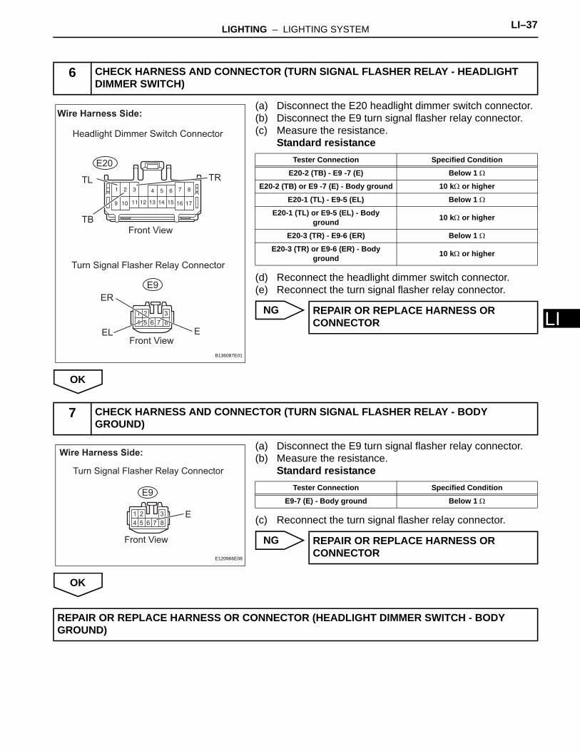
L(a) Disconnect the E20 headlight dimmer switch connector.(b) Disconnect the E9 turn signal flasher relay connector.(c) Measure the resistance.
Standard resistance
(d) Reconnect the headlight dimmer switch connector.(e) Reconnect the turn signal flasher relay connector.
NG
OK
(a) Disconnect the E9 turn signal flasher relay connector.(b) Measure the resistance.
Standard resistance
(c) Reconnect the turn signal flasher relay connector.
NG
OK
6 CHECK HARNESS AND CONNECTOR (TURN SIGNAL FLASHER RELAY - HEADLIGHT DIMMER SWITCH)
Wire Harness Side:
TL TR
TB
EL
ER
E
Headlight Dimmer Switch Connector
Front View
Front View
Turn Signal Flasher Relay Connector
E9
E20
B136087E01
Tester Connection Specified Condition
E20-2 (TB) - E9 -7 (E) Below 1 Ω
E20-2 (TB) or E9 -7 (E) - Body ground 10 kΩ or higher
E20-1 (TL) - E9-5 (EL) Below 1 Ω
E20-1 (TL) or E9-5 (EL) - Body ground 10 kΩ or higher
E20-3 (TR) - E9-6 (ER) Below 1 Ω
E20-3 (TR) or E9-6 (ER) - Body ground 10 kΩ or higher
REPAIR OR REPLACE HARNESS OR CONNECTOR
7 CHECK HARNESS AND CONNECTOR (TURN SIGNAL FLASHER RELAY - BODY GROUND)
Turn Signal Flasher Relay Connector
Wire Harness Side:
E
Front View
E9
E120966E08
Tester Connection Specified Condition
E9-7 (E) - Body ground Below 1 Ω
REPAIR OR REPLACE HARNESS OR CONNECTOR
REPAIR OR REPLACE HARNESS OR CONNECTOR (HEADLIGHT DIMMER SWITCH - BODY GROUND)
LI–38 LIGHTING – LIGHTING SYSTEM
LI
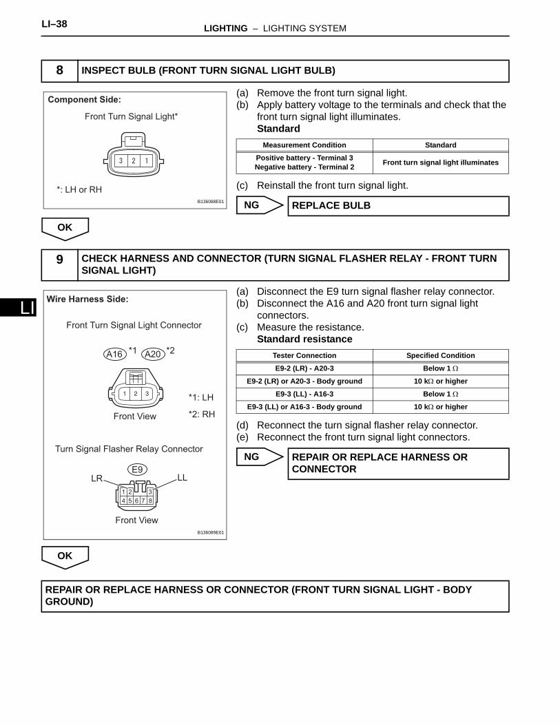
(a) Remove the front turn signal light.(b) Apply battery voltage to the terminals and check that the
front turn signal light illuminates.Standard
(c) Reinstall the front turn signal light.
NG
OK
(a) Disconnect the E9 turn signal flasher relay connector.(b) Disconnect the A16 and A20 front turn signal light
connectors.(c) Measure the resistance.
Standard resistance
(d) Reconnect the turn signal flasher relay connector.(e) Reconnect the front turn signal light connectors.
NG
OK
8 INSPECT BULB (FRONT TURN SIGNAL LIGHT BULB)
Component Side:
Front Turn Signal Light*
*: LH or RH
B136088E01
Measurement Condition Standard
Positive battery - Terminal 3Negative battery - Terminal 2 Front turn signal light illuminates
REPLACE BULB
9 CHECK HARNESS AND CONNECTOR (TURN SIGNAL FLASHER RELAY - FRONT TURN SIGNAL LIGHT)
Wire Harness Side:
LLLR
Front View
Front View
E9
Turn Signal Flasher Relay Connector
Front Turn Signal Light Connector
*1: LH
*2: RH
A16 A20*1 *2
B136089E01
Tester Connection Specified Condition
E9-2 (LR) - A20-3 Below 1 Ω
E9-2 (LR) or A20-3 - Body ground 10 kΩ or higher
E9-3 (LL) - A16-3 Below 1 Ω
E9-3 (LL) or A16-3 - Body ground 10 kΩ or higher
REPAIR OR REPLACE HARNESS OR CONNECTOR
REPAIR OR REPLACE HARNESS OR CONNECTOR (FRONT TURN SIGNAL LIGHT - BODY GROUND)
LIGHTING – LIGHTING SYSTEM LI–39
I
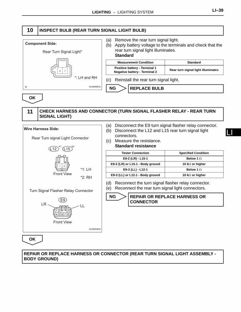
L(a) Remove the rear turn signal light. (b) Apply battery voltage to the terminals and check that the
rear turn signal light illuminates.Standard
(c) Reinstall the rear turn signal light.
NG
OK
(a) Disconnect the E9 turn signal flasher relay connector.(b) Disconnect the L12 and L15 rear turn signal light
connectors.(c) Measure the resistance.
Standard resistance
(d) Reconnect the turn signal flasher relay connector.(e) Reconnect the rear turn signal light connectors.
NG
OK
10 INSPECT BULB (REAR TURN SIGNAL LIGHT BULB)
12
Component Side:
Rear Turn Signal Light*
*: LH and RH
B136090E01
Measurement Condition Standard
Positive battery - Terminal 1Negative battery - Terminal 2 Rear turn signal light illuminates
REPLACE BULB
11 CHECK HARNESS AND CONNECTOR (TURN SIGNAL FLASHER RELAY - REAR TURN SIGNAL LIGHT)
1 2
Wire Harness Side:
LR LL
Rear Turn signal Light Connector
Front View*1: LH
*2: RH
Front View
Turn Signal Flasher Relay Connector
E9
L15L12 *1 *2
B136053E02
Tester Connection Specified Condition
E9-2 (LR) - L15-1 Below 1 Ω
E9-2 (LR) or L15-1 - Body ground 10 kΩ or higher
E9-3 (LL) - L12-1 Below 1 Ω
E9-3 (LL) or L12-1 - Body ground 10 kΩ or higher
REPAIR OR REPLACE HARNESS OR CONNECTOR
REPAIR OR REPLACE HARNESS OR CONNECTOR (REAR TURN SIGNAL LIGHT ASSEMBLY - BODY GROUND)
LI–40 LIGHTING – LIGHTING SYSTEM
LI
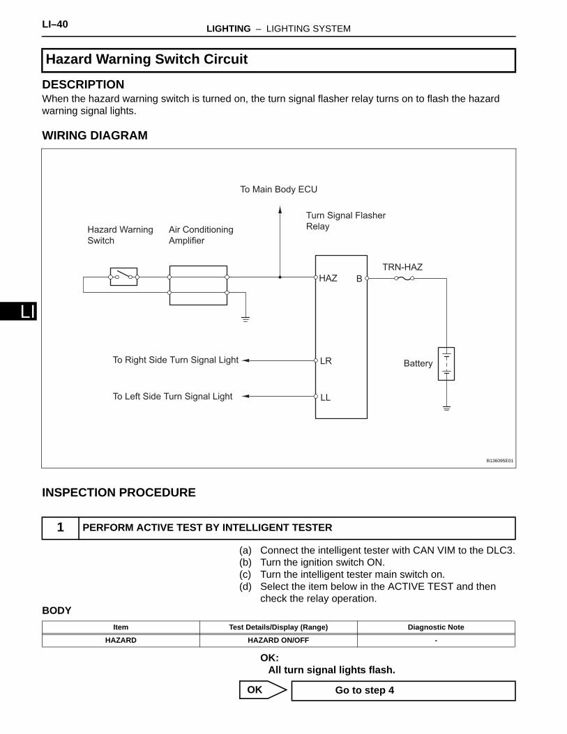
DESCRIPTIONWhen the hazard warning switch is turned on, the turn signal flasher relay turns on to flash the hazard warning signal lights.
WIRING DIAGRAM
INSPECTION PROCEDURE
(a) Connect the intelligent tester with CAN VIM to the DLC3.(b) Turn the ignition switch ON.(c) Turn the intelligent tester main switch on.(d) Select the item below in the ACTIVE TEST and then
check the relay operation.BODY
OK:All turn signal lights flash.
OK
Hazard Warning Switch Circuit
1 PERFORM ACTIVE TEST BY INTELLIGENT TESTER
Hazard Warning
Switch
Air Conditioning
Amplifier
Turn Signal Flasher
Relay
To Main Body ECU
HAZ
TRN-HAZ
B
LR
LL
BatteryTo Right Side Turn Signal Light
To Left Side Turn Signal Light
B136095E01
Item Test Details/Display (Range) Diagnostic Note
HAZARD HAZARD ON/OFF -
Go to step 4
LIGHTING – LIGHTING SYSTEM LI–41
I
LNG
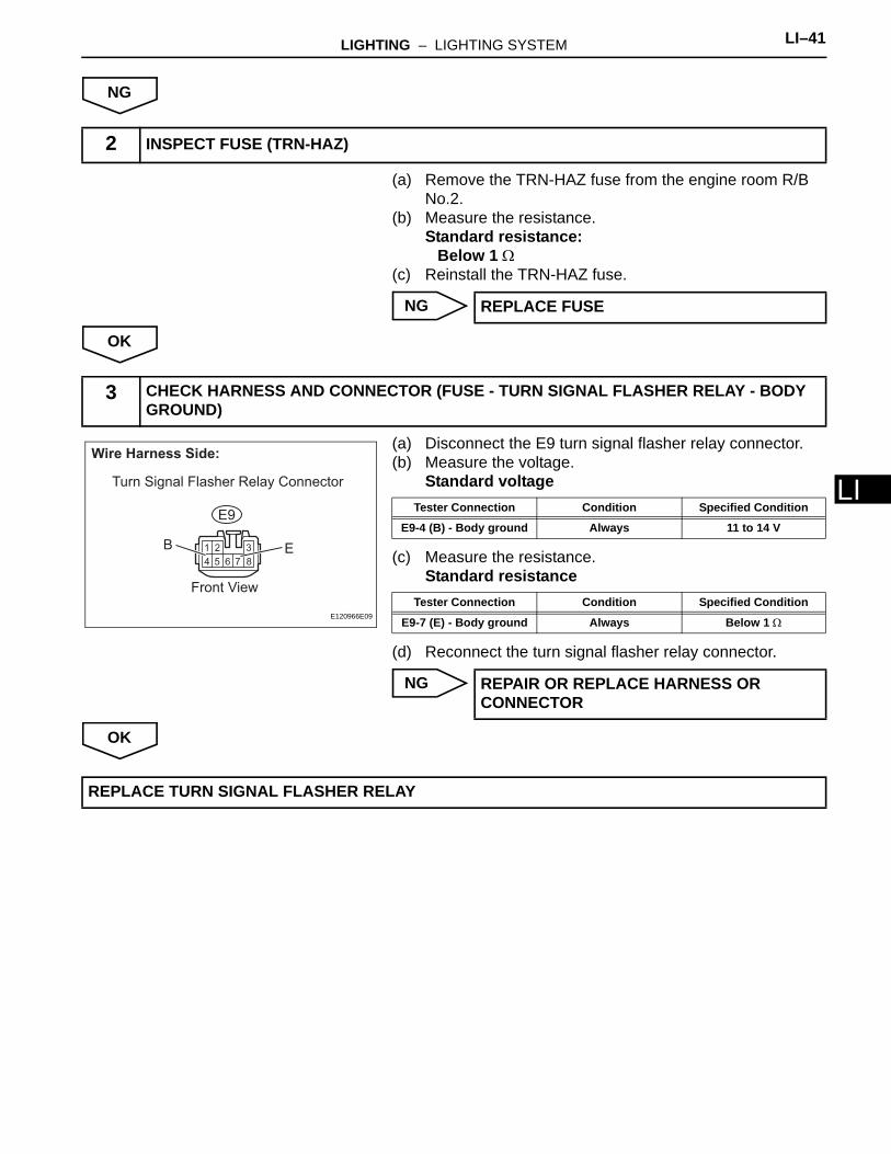
(a) Remove the TRN-HAZ fuse from the engine room R/B No.2.
(b) Measure the resistance.Standard resistance:
Below 1 Ω(c) Reinstall the TRN-HAZ fuse.
NG
OK
(a) Disconnect the E9 turn signal flasher relay connector.(b) Measure the voltage.
Standard voltage
(c) Measure the resistance.Standard resistance
(d) Reconnect the turn signal flasher relay connector.
NG
OK
2 INSPECT FUSE (TRN-HAZ)
REPLACE FUSE
3 CHECK HARNESS AND CONNECTOR (FUSE - TURN SIGNAL FLASHER RELAY - BODY GROUND)
Turn Signal Flasher Relay Connector
Wire Harness Side:
EB
Front View
E9
E120966E09
Tester Connection Condition Specified Condition
E9-4 (B) - Body ground Always 11 to 14 V
Tester Connection Condition Specified Condition
E9-7 (E) - Body ground Always Below 1 Ω
REPAIR OR REPLACE HARNESS OR CONNECTOR
REPLACE TURN SIGNAL FLASHER RELAY
LI–42 LIGHTING – LIGHTING SYSTEM
LI
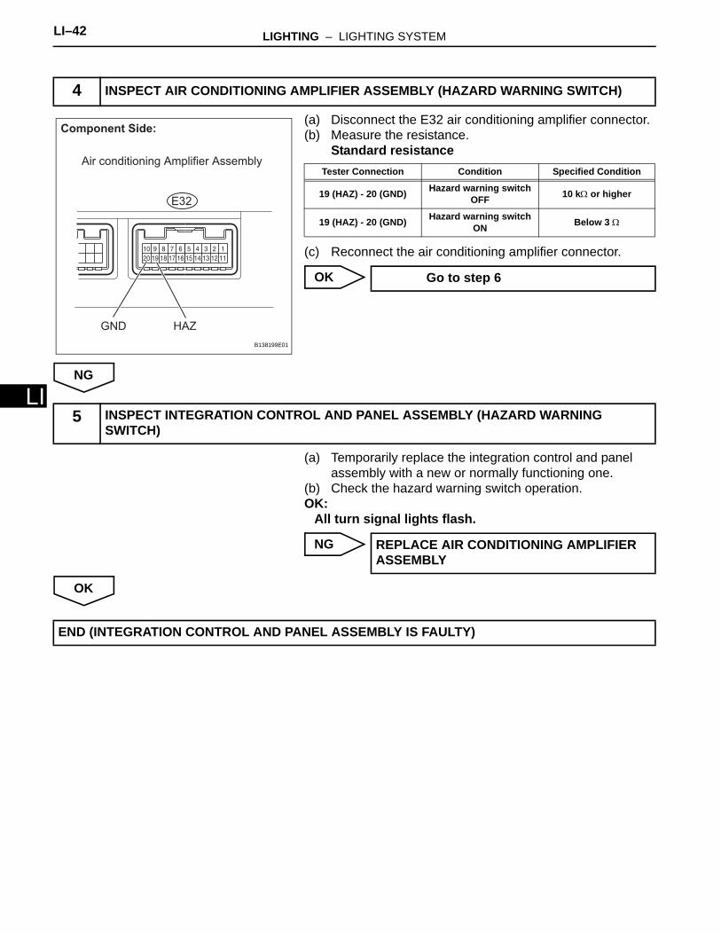
(a) Disconnect the E32 air conditioning amplifier connector.(b) Measure the resistance.
Standard resistance
(c) Reconnect the air conditioning amplifier connector.
OK
NG
(a) Temporarily replace the integration control and panel assembly with a new or normally functioning one.
(b) Check the hazard warning switch operation.OK:
All turn signal lights flash.
NG
OK
4 INSPECT AIR CONDITIONING AMPLIFIER ASSEMBLY (HAZARD WARNING SWITCH)
Component Side:
Air conditioning Amplifier Assembly
HAZGND
E32
B138199E01
Tester Connection Condition Specified Condition
19 (HAZ) - 20 (GND) Hazard warning switch OFF 10 kΩ or higher
19 (HAZ) - 20 (GND) Hazard warning switch ON Below 3 Ω
Go to step 6
5 INSPECT INTEGRATION CONTROL AND PANEL ASSEMBLY (HAZARD WARNING SWITCH)
REPLACE AIR CONDITIONING AMPLIFIER ASSEMBLY
END (INTEGRATION CONTROL AND PANEL ASSEMBLY IS FAULTY)
LIGHTING – LIGHTING SYSTEM LI–43
I
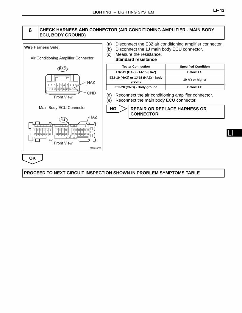
L(a) Disconnect the E32 air conditioning amplifier connector.(b) Disconnect the 1J main body ECU connector.(c) Measure the resistance.
Standard resistance
(d) Reconnect the air conditioning amplifier connector.(e) Reconnect the main body ECU connector.
NG
OK
6 CHECK HARNESS AND CONNECTOR (AIR CONDITIONING AMPLIFIER - MAIN BODY ECU, BODY GROUND)
1 2 3 4 5 6 7 8 9 10
11 12 13 14 15 16 17 18 19 20
Wire Harness Side:
HAZ
GND
HAZ
Air Conditioning Amplifier Connector
Front View
Front View
Main Body ECU Connector
1J
E32
B136096E01
Tester Connection Specified Condition
E32-19 (HAZ) - 1J-15 (HAZ) Below 1 Ω
E32-19 (HAZ) or 1J-15 (HAZ) - Body ground 10 kΩ or higher
E32-20 (GND) - Body ground Below 1 Ω
REPAIR OR REPLACE HARNESS OR CONNECTOR
PROCEED TO NEXT CIRCUIT INSPECTION SHOWN IN PROBLEM SYMPTOMS TABLE
LI–44 LIGHTING – LIGHTING SYSTEM
LI
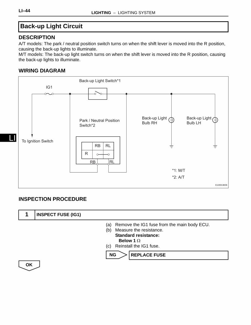
DESCRIPTIONA/T models: The park / neutral position switch turns on when the shift lever is moved into the R position, causing the back-up lights to illuminate.M/T models: The back-up light switch turns on when the shift lever is moved into the R position, causing the back-up lights to illuminate.
WIRING DIAGRAM
INSPECTION PROCEDURE
(a) Remove the IG1 fuse from the main body ECU.(b) Measure the resistance.
Standard resistance:Below 1 Ω
(c) Reinstall the IG1 fuse.
NG
OK
Back-up Light Circuit
1 INSPECT FUSE (IG1)
Park / Neutral Position
Switch*2
Back-up Light Switch*1
R
RB RL
Back-up Light
Bulb RH
IG1
*2: A/T
Back-up Light
Bulb LH
*1: M/T
RB RL
To Ignition Switch
E120013E06
REPLACE FUSE

LIGHTING – LIGHTING SYSTEM LI–45
I
L(a) Remove the back-up light bulb.(b) Apply battery voltage to the terminals and check that the
back-up light illuminates.Standard
(c) Reinstall the back-up light bulb.
NG
OK
(a) Check the vehicle's transaxle type.Result
B
A
(a) Disconnect the B35 park / neutral position switch.(b) Measure the resistance.
Standard resistance
(c) Reconnect the park / neutral position switch.
NG
OK
2 INSPECT BULB (BACK-UP LIGHT BULB)
12
Component Side:
Back-up Light*
*: LH and RH B141591E01
Measurement Condition Standard
Positive battery - Terminal 1Negative battery - Terminal 2 back-up light illuminates
REPLACE BULB
3 CHECK TRANSAXLE TYPE
Transaxle Type Proceed To
A/T A
M/T B
Go to step 7
4 INSPECT PARK / NEUTRAL POSITION SWITCH
Component Side:
RB RL
Park / Neutral Position Switch
C110340E33
Tester Connection Shift Position Specified Connection
2 (RB) - 1 (RL) R Below 1 Ω
2 (RB) - 1 (RL) Except R 10 kΩ or higher
REPLACE PARK / NEUTRAL POSITION SWITCH
LI–46 LIGHTING – LIGHTING SYSTEM
LI
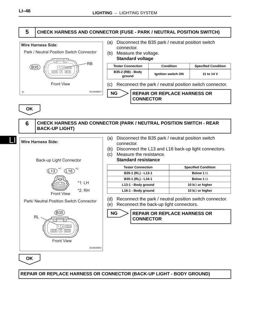
(a) Disconnect the B35 park / neutral position switch connector.
(b) Measure the voltage.Standard voltage
(c) Reconnect the park / neutral position switch connector.
NG
OK
(a) Disconnect the B35 park / neutral position switch connector.
(b) Disconnect the L13 and L16 back-up light connectors.(c) Measure the resistance.
Standard resistance
(d) Reconnect the park / neutral position switch connector.(e) Reconnect the back-up light connectors.
NG
OK
5 CHECK HARNESS AND CONNECTOR (FUSE - PARK / NEUTRAL POSITION SWITCH)
1 2 3
5 6 7 8 9
4
Wire Harness Side:
B35RB
Park / Neutral Position Switch Connector
Front View
B124048E07
Tester Connection Condition Specified Condition
B35-2 (RB) - Body ground Ignition switch ON 11 to 14 V
REPAIR OR REPLACE HARNESS OR CONNECTOR
6 CHECK HARNESS AND CONNECTOR (PARK / NEUTRAL POSITION SWITCH - REAR BACK-UP LIGHT)
Wire Harness Side:
RL
Back-up Light Connector
Front View
Front View
Park/ Neutral Position Switch Connector
*1: LH
*2: RH
B35
L13 L16*1 *2
B138183E01
Tester Connection Specified Condition
B35-1 (RL) - L13-1 Below 1 Ω
B35-1 (RL) - L16-1 Below 1 Ω
L13-1 - Body ground 10 kΩ or higher
L16-1 - Body ground 10 kΩ or higher
REPAIR OR REPLACE HARNESS OR CONNECTOR
REPAIR OR REPLACE HARNESS OR CONNECTOR (BACK-UP LIGHT - BODY GROUND)
LIGHTING – LIGHTING SYSTEM LI–47
I
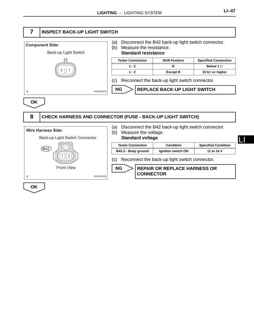
L(a) Disconnect the B42 back-up light switch connector.(b) Measure the resistance.
Standard resistance
(c) Reconnect the back-up light switch connector.
NG
OK
(a) Disconnect the B42 back-up light switch connector.(b) Measure the voltage.
Standard voltage
(c) Reconnect the back-up light switch connector.
NG
OK
7 INSPECT BACK-UP LIGHT SWITCH
12
Component Side:
Back-up Light Switch
B135322E03
Tester Connection Shift Position Specified Connection
1 - 2 R Below 1 Ω
1 - 2 Except R 10 kΩ or higher
REPLACE BACK-UP LIGHT SWITCH
8 CHECK HARNESS AND CONNECTOR (FUSE - BACK-UP LIGHT SWITCH)
1 2
Wire Harness Side:
Back-up Light Switch Connector
Front View
B42
B135323E02
Tester Connection Condition Specified Condition
B42-2 - Body ground Ignition switch ON 11 to 14 V
REPAIR OR REPLACE HARNESS OR CONNECTOR
LI–48 LIGHTING – LIGHTING SYSTEM
LI
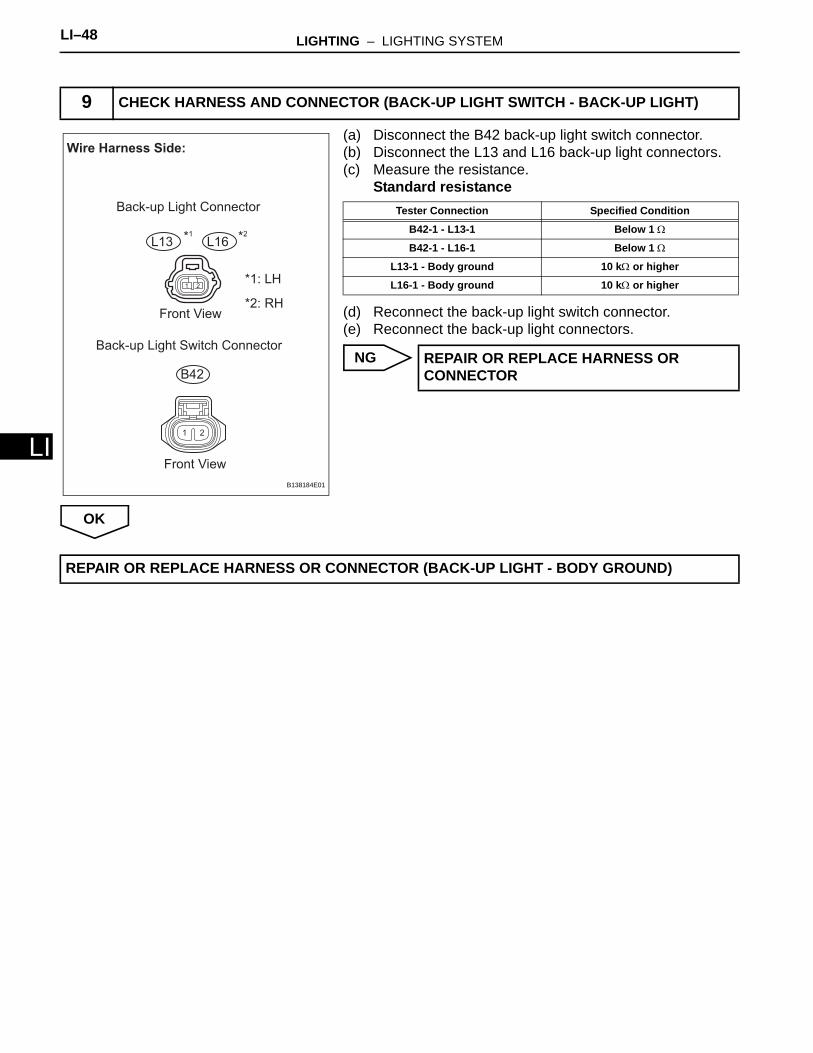
(a) Disconnect the B42 back-up light switch connector.(b) Disconnect the L13 and L16 back-up light connectors.(c) Measure the resistance.
Standard resistance
(d) Reconnect the back-up light switch connector.(e) Reconnect the back-up light connectors.
NG
OK
9 CHECK HARNESS AND CONNECTOR (BACK-UP LIGHT SWITCH - BACK-UP LIGHT)
1 2
Wire Harness Side:
Back-up Light Connector
Front View
Front View
Back-up Light Switch Connector
*1: LH
*2: RH
B42
L13 L16*1 *2
B138184E01
Tester Connection Specified Condition
B42-1 - L13-1 Below 1 Ω
B42-1 - L16-1 Below 1 Ω
L13-1 - Body ground 10 kΩ or higher
L16-1 - Body ground 10 kΩ or higher
REPAIR OR REPLACE HARNESS OR CONNECTOR
REPAIR OR REPLACE HARNESS OR CONNECTOR (BACK-UP LIGHT - BODY GROUND)
LIGHTING – LIGHTING SYSTEM LI–49
I
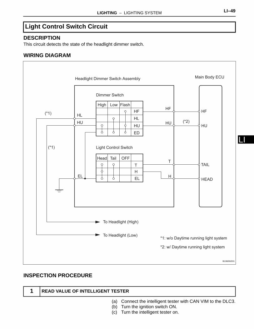
LDESCRIPTIONThis circuit detects the state of the headlight dimmer switch.
WIRING DIAGRAM
INSPECTION PROCEDURE
(a) Connect the intelligent tester with CAN VIM to the DLC3.(b) Turn the ignition switch ON.(c) Turn the intelligent tester on.
Light Control Switch Circuit
1 READ VALUE OF INTELLIGENT TESTER
Headlight Dimmer Switch Assembly
To Headlight (High)
*1: w/o Daytime running light system
*2: w/ Daytime running light system
To Headlight (Low)
Dimmer Switch
Light Control Switch
HF
H
T
H
T
HU
HF
HU
HF
HU
EL
(*1)
(*1)
(*2)
EL
TAIL
HLHU
HL
OFFTailHead
FlashLowHigh
ED
HEAD
Main Body ECU
B136091E01
LI–50 LIGHTING – LIGHTING SYSTEM
LI
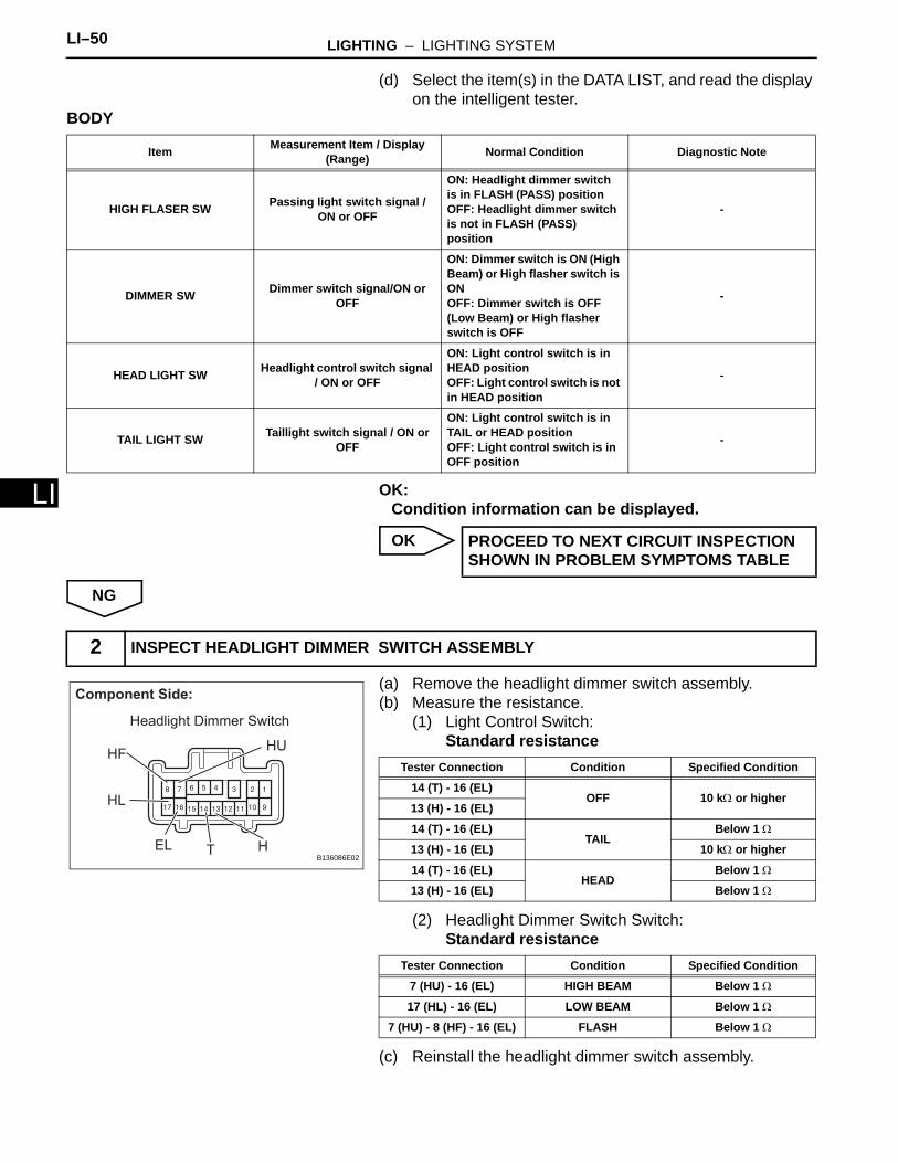
(d) Select the item(s) in the DATA LIST, and read the display on the intelligent tester.
BODY
OK:Condition information can be displayed.
OK
NG
(a) Remove the headlight dimmer switch assembly.(b) Measure the resistance.
(1) Light Control Switch:Standard resistance
(2) Headlight Dimmer Switch Switch:Standard resistance
(c) Reinstall the headlight dimmer switch assembly.
Item Measurement Item / Display (Range) Normal Condition Diagnostic Note
HIGH FLASER SW Passing light switch signal / ON or OFF
ON: Headlight dimmer switch is in FLASH (PASS) positionOFF: Headlight dimmer switch is not in FLASH (PASS) position
-
DIMMER SW Dimmer switch signal/ON or OFF
ON: Dimmer switch is ON (High Beam) or High flasher switch is ONOFF: Dimmer switch is OFF (Low Beam) or High flasher switch is OFF
-
HEAD LIGHT SW Headlight control switch signal / ON or OFF
ON: Light control switch is in HEAD positionOFF: Light control switch is not in HEAD position
-
TAIL LIGHT SW Taillight switch signal / ON or OFF
ON: Light control switch is in TAIL or HEAD positionOFF: Light control switch is in OFF position
-
PROCEED TO NEXT CIRCUIT INSPECTION SHOWN IN PROBLEM SYMPTOMS TABLE
2 INSPECT HEADLIGHT DIMMER SWITCH ASSEMBLY
Component Side:
HL
HFHU
EL T H
Headlight Dimmer Switch
B136086E02
Tester Connection Condition Specified Condition
14 (T) - 16 (EL)OFF 10 kΩ or higher
13 (H) - 16 (EL)
14 (T) - 16 (EL)TAIL
Below 1 Ω
13 (H) - 16 (EL) 10 kΩ or higher
14 (T) - 16 (EL)HEAD
Below 1 Ω
13 (H) - 16 (EL) Below 1 Ω
Tester Connection Condition Specified Condition
7 (HU) - 16 (EL) HIGH BEAM Below 1 Ω
17 (HL) - 16 (EL) LOW BEAM Below 1 Ω
7 (HU) - 8 (HF) - 16 (EL) FLASH Below 1 Ω

LIGHTING – LIGHTING SYSTEM LI–51
I
LNG
OK
(a) Disconnect the E8 main body ECU connector.(b) Disconnect the E20 headlight dimmer switch assembly
connector.(c) Measure the resistance.Standard resistance
HINT:*: w/ Daytime running light system(d) Reconnect the main body ECU connector.(e) Reconnect the headlight dimmer switch assembly
connector.
NG
OK
HINT:*: w/o Daytime running light system
REPLACE HEADLIGHT DIMMER SWITCH ASSEMBLY
3 CHECK HARNESS AND CONNECTOR (HEADLIGHT DIMMER SWITCH - MAIN BODY ECU)
2322 2618
107
25
13 14 16 17
19
8
20
9 11 12 15
2421
1 2 3 4 5 6
Wire Harness Side:
HF
EL
HU
HU
H
HF
TAIL
HEAD
T
Main Body ECU Connector
Front View
Front View
Headlight Dimmer Switch Assembly
Connector
E20
E8
B138177E01
Tester Connection Specified Condition
E20-8 (HF) - E8-7 (HF) Below 1 Ω
E20-8 (HF) or E8-7 (HF) - Body ground 10 kΩ or higher
E20-14 (T) - E8-8 (TAIL) Below 1 Ω
E20-14 (T) or E8-8 (TAIL) - Body ground 10 kΩ or higher
E20-13 (H) - E8-1 (HEAD) Below 1 Ω
E20-13 (H) or E8-1 (HEAD) - Body ground 10 kΩ or higher
E20-7 (HU) - E8-2 (HU)* Below 1 Ω
E20-7 (HU) or E8-2 (HU)* - Body ground 10 kΩ or higher
E20-16 (EL) - Body ground Below 1 Ω
REPAIR OR REPLACE HARNESS OR CONNECTOR
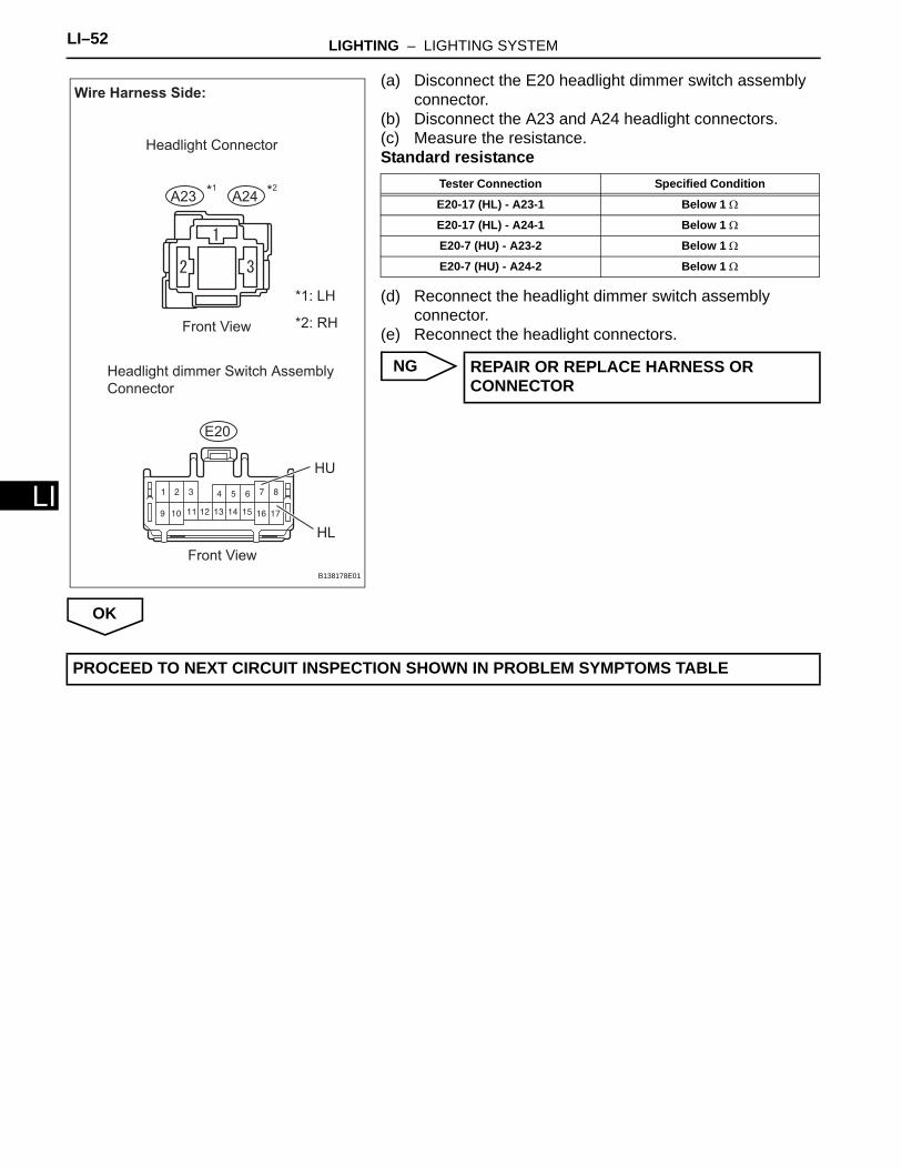
4 CHECK HARNESS AND CONNECTOR (HEADLIGHT DIMMER SWITCH - HEADLIGHT*)
LI–52 LIGHTING – LIGHTING SYSTEM
LI
(a) Disconnect the E20 headlight dimmer switch assembly connector.
(b) Disconnect the A23 and A24 headlight connectors.(c) Measure the resistance.Standard resistance
(d) Reconnect the headlight dimmer switch assembly connector.
(e) Reconnect the headlight connectors.
NG
OK
Wire Harness Side:
HL
HU
Headlight Connector
Front View
Front View
Headlight dimmer Switch Assembly
Connector
*1: LH
*2: RH
E20
A23 A24*1 *2
B138178E01
Tester Connection Specified Condition
E20-17 (HL) - A23-1 Below 1 Ω
E20-17 (HL) - A24-1 Below 1 Ω
E20-7 (HU) - A23-2 Below 1 Ω
E20-7 (HU) - A24-2 Below 1 Ω
REPAIR OR REPLACE HARNESS OR CONNECTOR
PROCEED TO NEXT CIRCUIT INSPECTION SHOWN IN PROBLEM SYMPTOMS TABLE
LIGHTING – LIGHTING SYSTEM LI–53
I
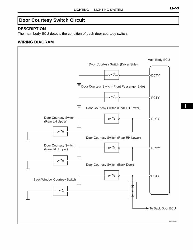
LDESCRIPTIONThe main body ECU detects the condition of each door courtesy switch.
WIRING DIAGRAM
Door Courtesy Switch Circuit
Door Courtesy Switch (Driver Side)
Door Courtesy Switch
(Rear LH Upper)
Door Courtesy Switch (Rear LH Lower)
Door Courtesy Switch
(Rear RH Upper)
Door Courtesy Switch (Rear RH Lower)
Door Courtesy Switch (Back Door)
Back Window Courtesy Switch
Door Courtesy Switch (Front Passenger Side)
DCTY
PCTY
RLCY
RRCY
BCTY
To Back Door ECU
Main Body ECU
B136092E01
LI–54 LIGHTING – LIGHTING SYSTEM
LI
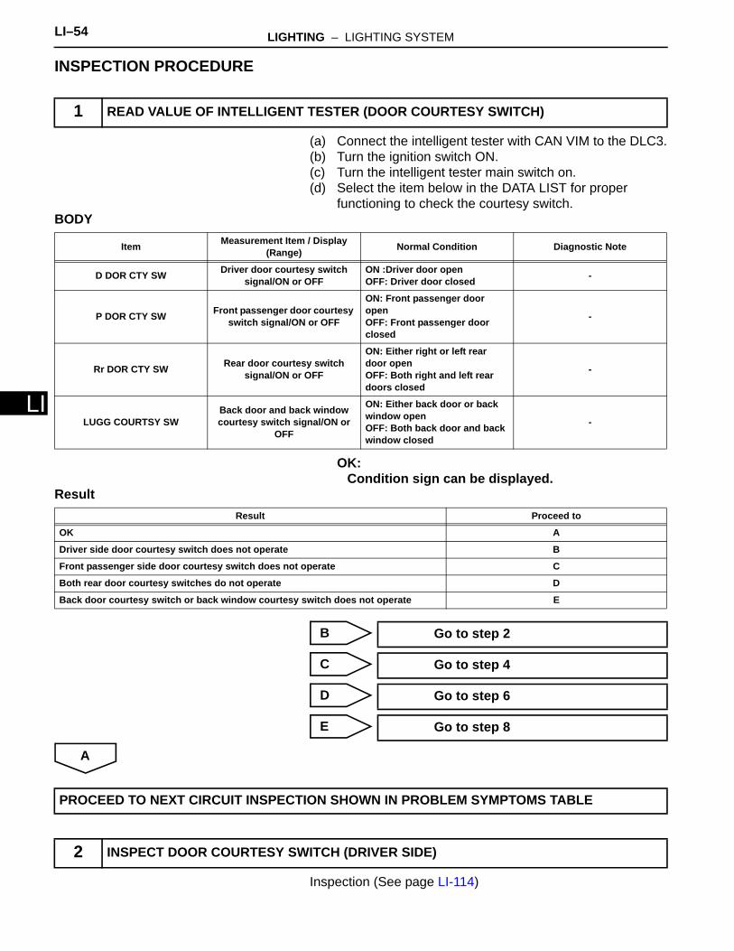
INSPECTION PROCEDURE
(a) Connect the intelligent tester with CAN VIM to the DLC3.(b) Turn the ignition switch ON.(c) Turn the intelligent tester main switch on.(d) Select the item below in the DATA LIST for proper
functioning to check the courtesy switch.BODY
OK:Condition sign can be displayed.
Result
B
C
D
E
A
Inspection (See page LI-114)
1 READ VALUE OF INTELLIGENT TESTER (DOOR COURTESY SWITCH)
Item Measurement Item / Display(Range) Normal Condition Diagnostic Note
D DOR CTY SW Driver door courtesy switch signal/ON or OFF
ON :Driver door openOFF: Driver door closed -
P DOR CTY SW Front passenger door courtesy switch signal/ON or OFF
ON: Front passenger door openOFF: Front passenger door closed
-
Rr DOR CTY SW Rear door courtesy switch signal/ON or OFF
ON: Either right or left rear door openOFF: Both right and left rear doors closed
-
LUGG COURTSY SWBack door and back window courtesy switch signal/ON or
OFF
ON: Either back door or back window openOFF: Both back door and back window closed
-
Result Proceed to
OK A
Driver side door courtesy switch does not operate B
Front passenger side door courtesy switch does not operate C
Both rear door courtesy switches do not operate D
Back door courtesy switch or back window courtesy switch does not operate E
Go to step 2
Go to step 4
Go to step 6
Go to step 8
PROCEED TO NEXT CIRCUIT INSPECTION SHOWN IN PROBLEM SYMPTOMS TABLE
2 INSPECT DOOR COURTESY SWITCH (DRIVER SIDE)
LIGHTING – LIGHTING SYSTEM LI–55
I
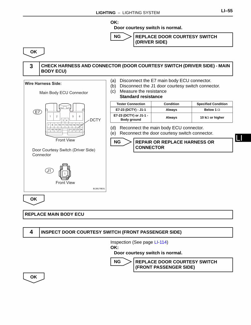
LOK:Door courtesy switch is normal.
NG
OK
(a) Disconnect the E7 main body ECU connector.(b) Disconnect the J1 door courtesy switch connector.(c) Measure the resistance
Standard resistance
(d) Reconnect the main body ECU connector.(e) Reconnect the door courtesy switch connector.
NG
OK
Inspection (See page LI-114)OK:
Door courtesy switch is normal.
NG
OK
REPLACE DOOR COURTESY SWITCH (DRIVER SIDE)
3 CHECK HARNESS AND CONNECTOR (DOOR COURTESY SWITCH (DRIVER SIDE) - MAIN BODY ECU)
222117
107
24
13 14 16
18
8
19
9 11 12 15
2320
1 2
3 4
5 6
1
Wire Harness Side:
DCTY
Main Body ECU Connector
Front View
Front View
Door Courtesy Switch (Driver Side)
Connector
E7
J1
B138179E01
Tester Connection Condition Specified Condition
E7-23 (DCTY) - J1-1 Always Below 1 Ω
E7-23 (DCTY) or J1-1 - Body ground Always 10 kΩ or higher
REPAIR OR REPLACE HARNESS OR CONNECTOR
REPLACE MAIN BODY ECU
4 INSPECT DOOR COURTESY SWITCH (FRONT PASSENGER SIDE)
REPLACE DOOR COURTESY SWITCH (FRONT PASSENGER SIDE)
LI–56 LIGHTING – LIGHTING SYSTEM
LI
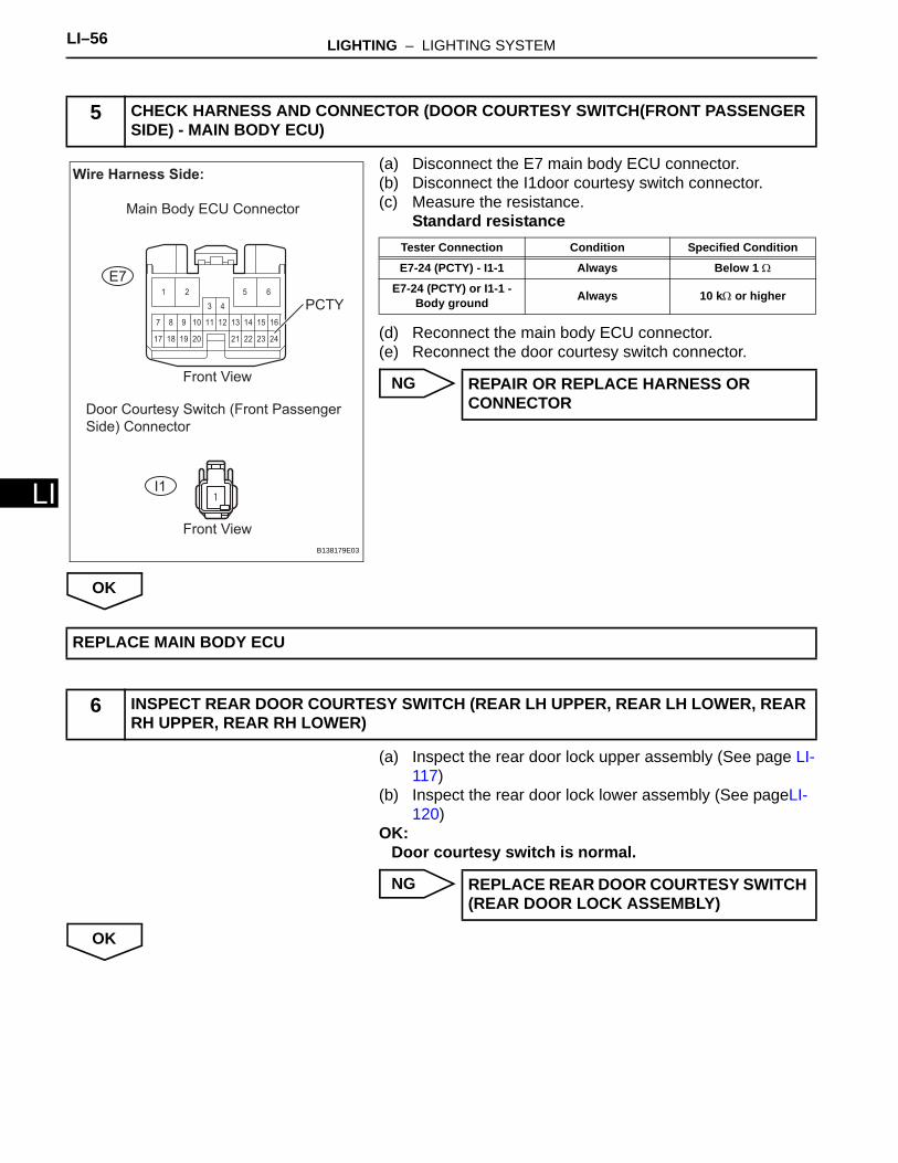
(a) Disconnect the E7 main body ECU connector.(b) Disconnect the I1door courtesy switch connector.(c) Measure the resistance.
Standard resistance
(d) Reconnect the main body ECU connector.(e) Reconnect the door courtesy switch connector.
NG
OK
(a) Inspect the rear door lock upper assembly (See page LI-117)
(b) Inspect the rear door lock lower assembly (See pageLI-120)
OK:Door courtesy switch is normal.
NG
OK
5 CHECK HARNESS AND CONNECTOR (DOOR COURTESY SWITCH(FRONT PASSENGER SIDE) - MAIN BODY ECU)
222117
107
24
13 14 16
18
8
19
9 11 12 15
2320
1 2
3 4
5 6
1
Wire Harness Side:
PCTY
Front View
Front View
Door Courtesy Switch (Front Passenger
Side) Connector
E7
I1
Main Body ECU Connector
B138179E03
Tester Connection Condition Specified Condition
E7-24 (PCTY) - I1-1 Always Below 1 Ω
E7-24 (PCTY) or I1-1 - Body ground Always 10 kΩ or higher
REPAIR OR REPLACE HARNESS OR CONNECTOR
REPLACE MAIN BODY ECU
6 INSPECT REAR DOOR COURTESY SWITCH (REAR LH UPPER, REAR LH LOWER, REAR RH UPPER, REAR RH LOWER)
REPLACE REAR DOOR COURTESY SWITCH (REAR DOOR LOCK ASSEMBLY)
LIGHTING – LIGHTING SYSTEM LI–57
I
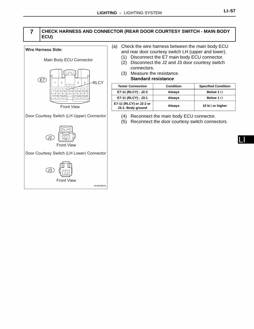
L(a) Check the wire harness between the main body ECU and rear door courtesy switch LH (upper and lower).(1) Disconnect the E7 main body ECU connector.(2) Disconnect the J2 and J3 door courtesy switch
connectors.(3) Measure the resistance.
Standard resistance
(4) Reconnect the main body ECU connector.(5) Reconnect the door courtesy switch connectors.
7 CHECK HARNESS AND CONNECTOR (REAR DOOR COURTESY SWITCH - MAIN BODY ECU)
222117
107
24
13 14 16
18
8
19
9 11 12 15
2320
1 2
3 4
5 6
Wire Harness Side:
RLCY
Front View
Front View
Front View
Door Courtesy Switch (LH Upper) Connector
Door Courtesy Switch (LH Lower) Connector
E7
J2
J3
Main Body ECU Connector
B138180E01
Tester Connection Condition Specified Condition
E7-11 (RLCY) - J2-2 Always Below 1 Ω
E7-11 (RLCY) - J3-1 Always Below 1 Ω
E7-11 (RLCY) or J2-2 or J3-1- Body ground Always 10 kΩ or higher
LI–58 LIGHTING – LIGHTING SYSTEM
LI
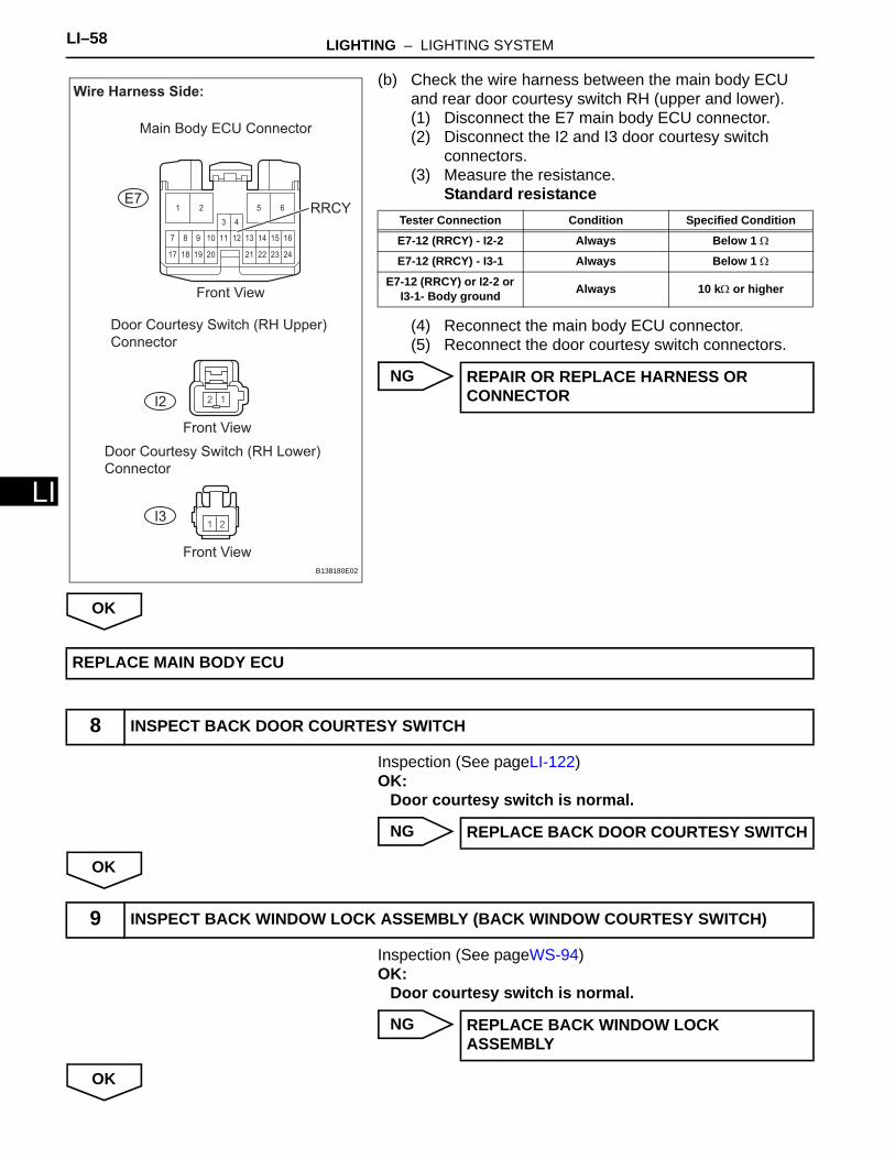
(b) Check the wire harness between the main body ECU and rear door courtesy switch RH (upper and lower).(1) Disconnect the E7 main body ECU connector.(2) Disconnect the I2 and I3 door courtesy switch
connectors.(3) Measure the resistance.
Standard resistance
(4) Reconnect the main body ECU connector.(5) Reconnect the door courtesy switch connectors.
NG
OK
Inspection (See pageLI-122)OK:
Door courtesy switch is normal.
NG
OK
Inspection (See pageWS-94)OK:
Door courtesy switch is normal.
NG
OK
222117
107
24
13 14 16
18
8
19
9 11 12 15
2320
1 2
3 4
5 6
Wire Harness Side:
RRCY
Front View
Front View
Front View
Door Courtesy Switch (RH Upper)
Connector
Door Courtesy Switch (RH Lower)
Connector
E7
I2
I3
Main Body ECU Connector
B138180E02
Tester Connection Condition Specified Condition
E7-12 (RRCY) - I2-2 Always Below 1 Ω
E7-12 (RRCY) - I3-1 Always Below 1 Ω
E7-12 (RRCY) or I2-2 or I3-1- Body ground Always 10 kΩ or higher
REPAIR OR REPLACE HARNESS OR CONNECTOR
REPLACE MAIN BODY ECU
8 INSPECT BACK DOOR COURTESY SWITCH
REPLACE BACK DOOR COURTESY SWITCH
9 INSPECT BACK WINDOW LOCK ASSEMBLY (BACK WINDOW COURTESY SWITCH)
REPLACE BACK WINDOW LOCK ASSEMBLY
LIGHTING – LIGHTING SYSTEM LI–59
I
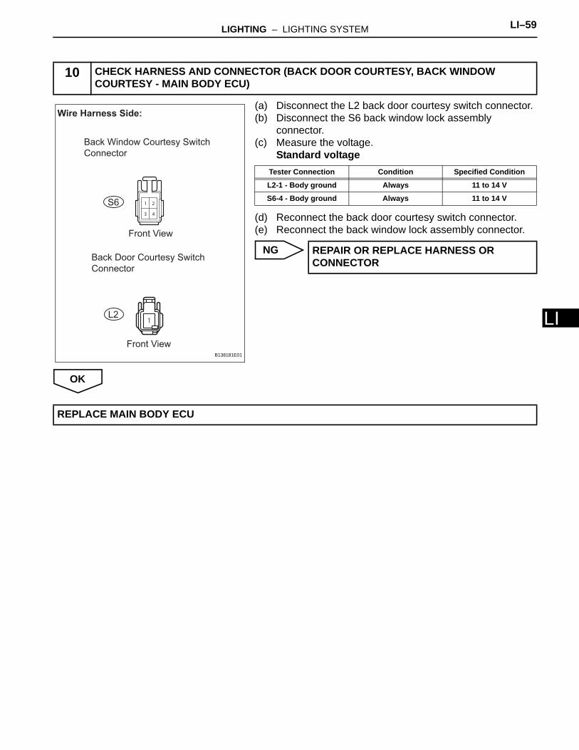
L(a) Disconnect the L2 back door courtesy switch connector.(b) Disconnect the S6 back window lock assembly
connector.(c) Measure the voltage.
Standard voltage
(d) Reconnect the back door courtesy switch connector.(e) Reconnect the back window lock assembly connector.
NG
OK
10 CHECK HARNESS AND CONNECTOR (BACK DOOR COURTESY, BACK WINDOW COURTESY - MAIN BODY ECU)
1
2
3 4
1
Wire Harness Side:
Back Window Courtesy Switch
Connector
Front View
Front View
Back Door Courtesy Switch
Connector
S6
L2
B138181E01
Tester Connection Condition Specified Condition
L2-1 - Body ground Always 11 to 14 V
S6-4 - Body ground Always 11 to 14 V
REPAIR OR REPLACE HARNESS OR CONNECTOR
REPLACE MAIN BODY ECU
LI–60 LIGHTING – LIGHTING SYSTEM
LI
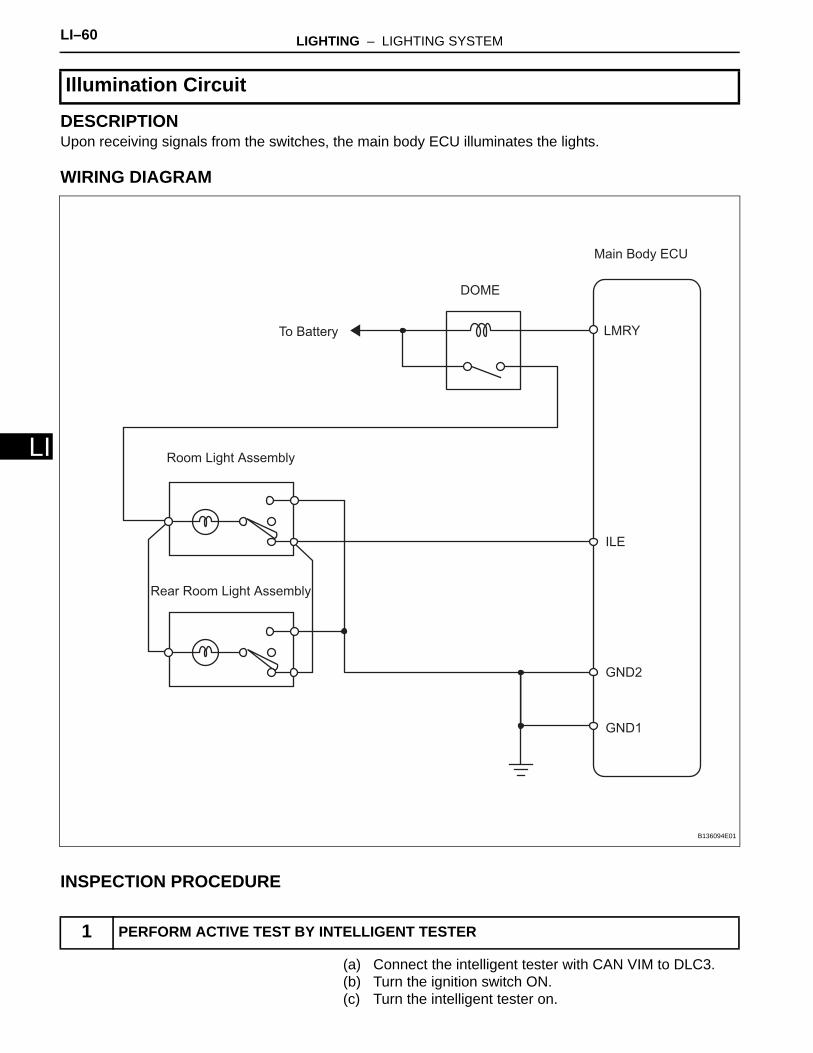
DESCRIPTIONUpon receiving signals from the switches, the main body ECU illuminates the lights.
WIRING DIAGRAM
INSPECTION PROCEDURE
(a) Connect the intelligent tester with CAN VIM to DLC3.(b) Turn the ignition switch ON.(c) Turn the intelligent tester on.
Illumination Circuit
1 PERFORM ACTIVE TEST BY INTELLIGENT TESTER
Main Body ECU
Room Light Assembly
DOME
ILE
LMRY
GND2
To Battery
GND1
Rear Room Light Assembly
B136094E01
LIGHTING – LIGHTING SYSTEM LI–61
I
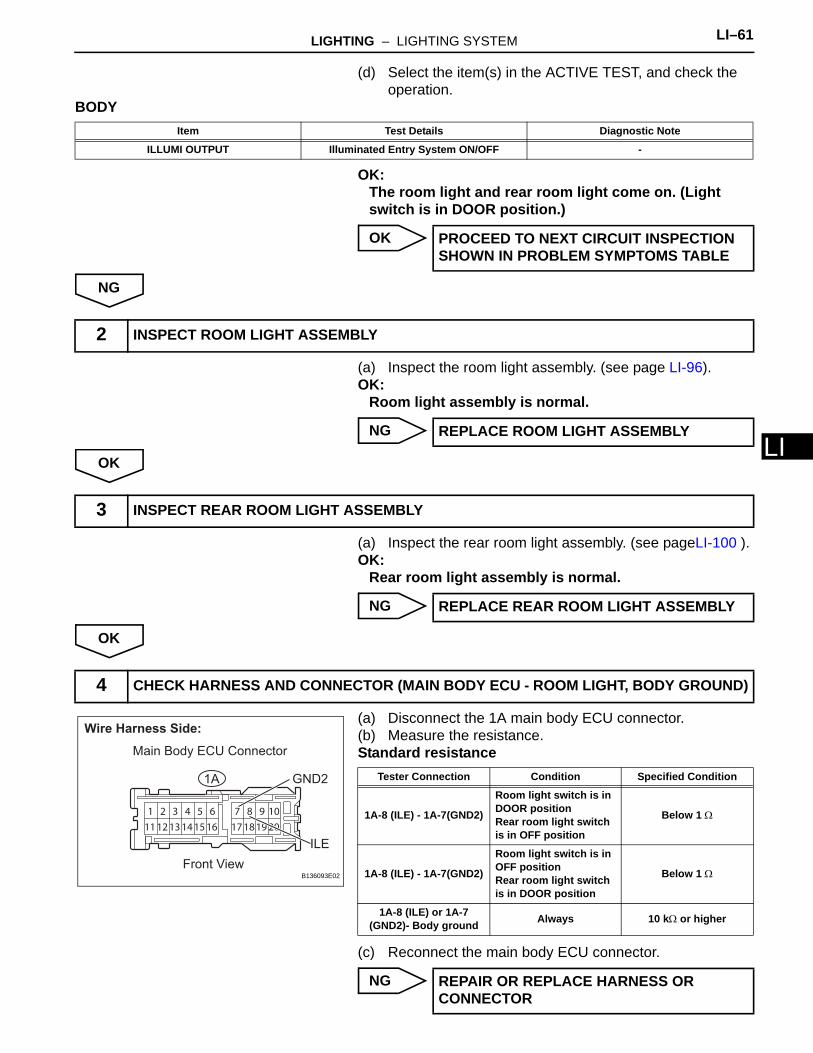
L(d) Select the item(s) in the ACTIVE TEST, and check the operation.
BODY
OK:The room light and rear room light come on. (Light switch is in DOOR position.)
OK
NG
(a) Inspect the room light assembly. (see page LI-96).OK:
Room light assembly is normal.
NG
OK
(a) Inspect the rear room light assembly. (see pageLI-100 ).OK:
Rear room light assembly is normal.
NG
OK
(a) Disconnect the 1A main body ECU connector.(b) Measure the resistance.Standard resistance
(c) Reconnect the main body ECU connector.
NG
Item Test Details Diagnostic Note
ILLUMI OUTPUT Illuminated Entry System ON/OFF -
PROCEED TO NEXT CIRCUIT INSPECTION SHOWN IN PROBLEM SYMPTOMS TABLE
2 INSPECT ROOM LIGHT ASSEMBLY
REPLACE ROOM LIGHT ASSEMBLY
3 INSPECT REAR ROOM LIGHT ASSEMBLY
REPLACE REAR ROOM LIGHT ASSEMBLY
4 CHECK HARNESS AND CONNECTOR (MAIN BODY ECU - ROOM LIGHT, BODY GROUND)
1
11
2
12
3
13
4
14
5
15
6
16
7
17
8
18
9
19
10
20
Wire Harness Side:
Front View
ILE
GND21A
Main Body ECU Connector
B136093E02
Tester Connection Condition Specified Condition
1A-8 (ILE) - 1A-7(GND2)
Room light switch is in DOOR positionRear room light switch is in OFF position
Below 1 Ω
1A-8 (ILE) - 1A-7(GND2)
Room light switch is in OFF positionRear room light switch is in DOOR position
Below 1 Ω
1A-8 (ILE) or 1A-7 (GND2)- Body ground Always 10 kΩ or higher
REPAIR OR REPLACE HARNESS OR CONNECTOR
LI–62 LIGHTING – LIGHTING SYSTEM
LI
OK
REPLACE MAIN BODY ECU
LIGHTING – LIGHTING SYSTEM LI–63
I
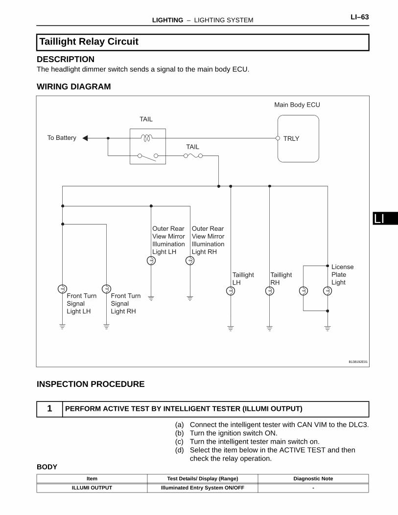
LDESCRIPTIONThe headlight dimmer switch sends a signal to the main body ECU.
WIRING DIAGRAM
INSPECTION PROCEDURE
(a) Connect the intelligent tester with CAN VIM to the DLC3.(b) Turn the ignition switch ON.(c) Turn the intelligent tester main switch on.(d) Select the item below in the ACTIVE TEST and then
check the relay operation.BODY
Taillight Relay Circuit
1 PERFORM ACTIVE TEST BY INTELLIGENT TESTER (ILLUMI OUTPUT)
TAIL
To Battery
TAIL
TRLY
Front Turn
Signal
Light LH
Front Turn
Signal
Light RH
Outer Rear
View Mirror
Illumination
Light LH
Outer Rear
View Mirror
Illumination
Light RH
Taillight
LH
Taillight
RH
License
Plate
Light
Main Body ECU
B138192E01
Item Test Details/ Display (Range) Diagnostic Note
ILLUMI OUTPUT Illuminated Entry System ON/OFF -

LI–64 LIGHTING – LIGHTING SYSTEM
LI
Result
B
C
D
E
A
(a) Remove the TAIL fuse from the main body ECU.(b) Measure the resistance.Standard resistance:
Below 1 Ω(c) Reinstall the TAIL fuse.
NG
OK
(a) Remove the TAIL relay from the main body ECU.(b) Measure the resistance.Standard resistance
(c) Reinstall the TAIL relay.
NG
Result Proceed to
OK A
No illumination lights illuminate B
Front turn signal light does not illuminate C
Taillight or license plate light does not illuminate D
Outer rear view mirror illumination light does not illuminate E
Go to step 2
Go to step 5
Go to step 7
Go to step 10
PROCEED TO NEXT CIRCUIT INSPECTION SHOWN IN PROBLEM SYMPTOMS TABLE
2 INSPECT FUSE (TAIL FUSE)
REPLACE FUSE
3 INSPECT TAIL RELAY
Battery
Ohmmeter
E109078E06
Tester Connection Specified Condition
3 - 5 10 kΩ or higher
3 - 5 Below 1 Ω (When battery voltage is applied between terminals 1 and 2)
REPLACE TAIL RELAY

LIGHTING – LIGHTING SYSTEM LI–65
I
LOK
(a) Remove the TAIL relay from the main body ECU.(b) Measure the resistance.Standard resistance
(c) Reinstall the TAIL relay.
NG
OK
(a) Remove the front turn signal lights.(b) Apply battery voltage to the terminals and check that the
front turn signal light illuminates.Standard
(c) Reinstall the front turn signal lights.
NG
OK
4 CHECK HARNESS AND CONNECTOR (BATTERY - TAIL RELAY)
Component Side:
Main Body ECU
B138193E01
Tester Connection Condition Specified Condition
1 - Body ground Always 11 to 14 V
5 - Body ground Always 11 to 14 V
REPAIR OR REPLACE HARNESS OR CONNECTOR
REPLACE MAIN BODY ECU
5 INSPECT BULB (FRONT TURN SIGNAL LIGHT)
Component Side:
Front Turn Signal Light*
*: LH or RH
B136088E01
Measurement Condition Standard
Positive battery - Terminal 1Negative battery - Terminal 2 Front turn signal light illuminates
REPLACE BULB
LI–66 LIGHTING – LIGHTING SYSTEM
LI
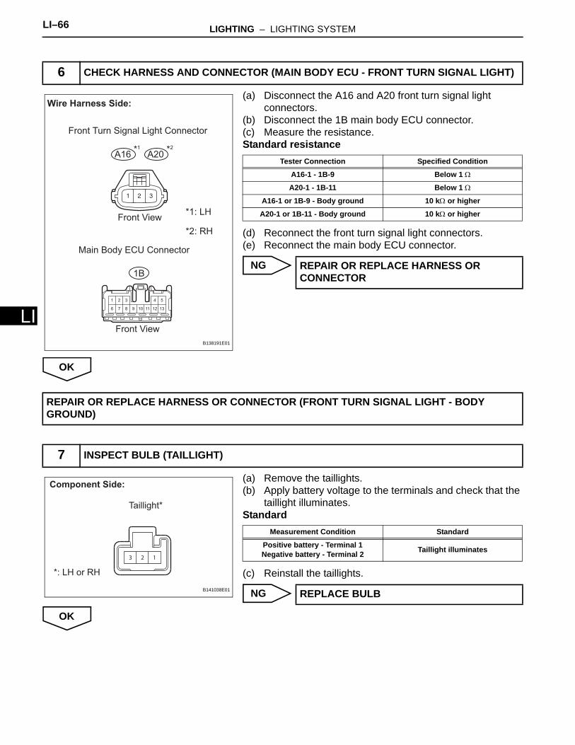
(a) Disconnect the A16 and A20 front turn signal light connectors.
(b) Disconnect the 1B main body ECU connector.(c) Measure the resistance.Standard resistance
(d) Reconnect the front turn signal light connectors.(e) Reconnect the main body ECU connector.
NG
OK
(a) Remove the taillights.(b) Apply battery voltage to the terminals and check that the
taillight illuminates.Standard
(c) Reinstall the taillights.
NG
OK
6 CHECK HARNESS AND CONNECTOR (MAIN BODY ECU - FRONT TURN SIGNAL LIGHT)
1 2 3 4 5
6 7 8 9 10 11 12 13
1B
A16 A20
Wire Harness Side:
Front View
Front View
Main Body ECU Connector
*1: LH
*2: RH
Front Turn Signal Light Connector
*1 *2
B138191E01
Tester Connection Specified Condition
A16-1 - 1B-9 Below 1 Ω
A20-1 - 1B-11 Below 1 Ω
A16-1 or 1B-9 - Body ground 10 kΩ or higher
A20-1 or 1B-11 - Body ground 10 kΩ or higher
REPAIR OR REPLACE HARNESS OR CONNECTOR
REPAIR OR REPLACE HARNESS OR CONNECTOR (FRONT TURN SIGNAL LIGHT - BODY GROUND)
7 INSPECT BULB (TAILLIGHT)
123
Component Side:
*: LH or RH
Taillight*
B141038E01
Measurement Condition Standard
Positive battery - Terminal 1Negative battery - Terminal 2 Taillight illuminates
REPLACE BULB
LIGHTING – LIGHTING SYSTEM LI–67
I
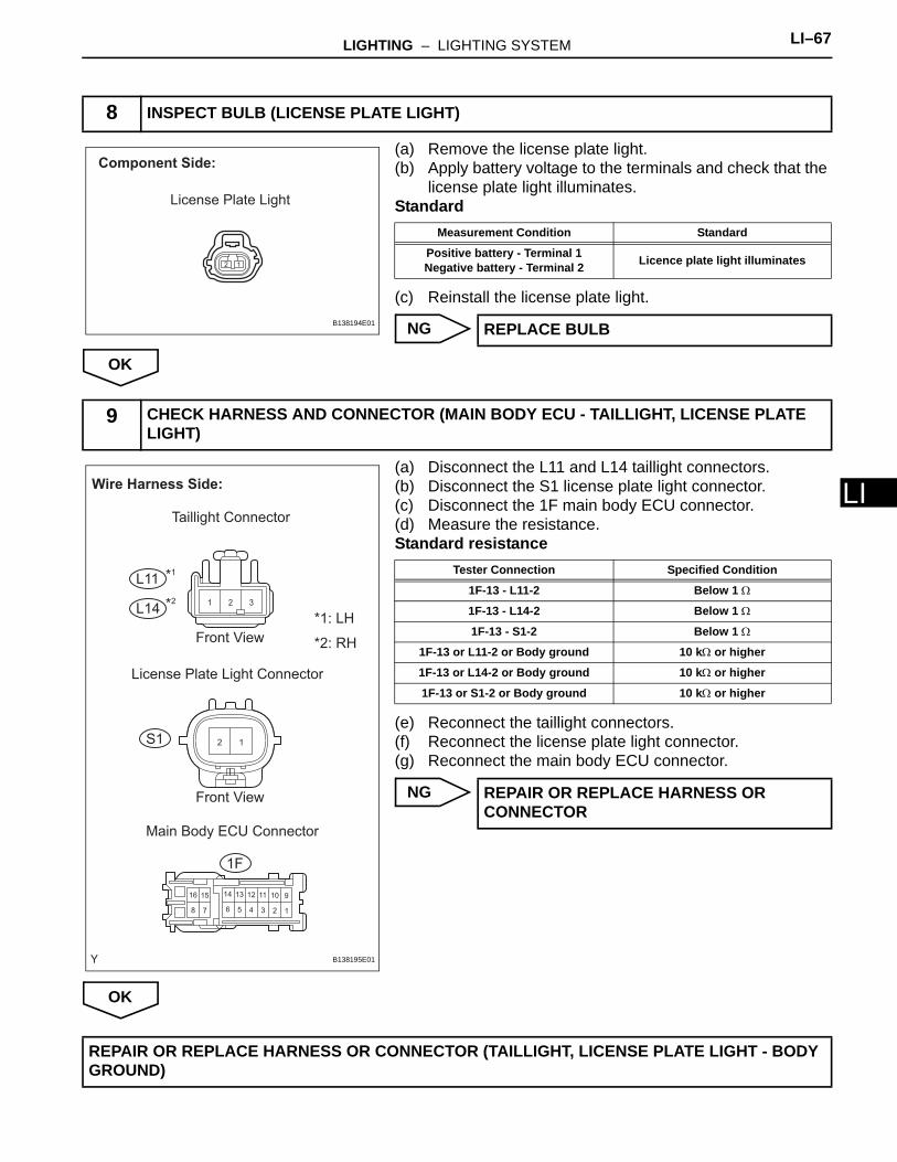
L(a) Remove the license plate light.(b) Apply battery voltage to the terminals and check that the
license plate light illuminates.Standard
(c) Reinstall the license plate light.
NG
OK
(a) Disconnect the L11 and L14 taillight connectors.(b) Disconnect the S1 license plate light connector.(c) Disconnect the 1F main body ECU connector.(d) Measure the resistance.Standard resistance
(e) Reconnect the taillight connectors.(f) Reconnect the license plate light connector.(g) Reconnect the main body ECU connector.
NG
OK
8 INSPECT BULB (LICENSE PLATE LIGHT)
Component Side:
License Plate Light
B138194E01
Measurement Condition Standard
Positive battery - Terminal 1Negative battery - Terminal 2 Licence plate light illuminates
REPLACE BULB
9 CHECK HARNESS AND CONNECTOR (MAIN BODY ECU - TAILLIGHT, LICENSE PLATE LIGHT)
12
1 2 3
123456
91011121314
78
1516
1F
S1
L11
L14
Wire Harness Side:
Front View
Taillight Connector
Front View
License Plate Light Connector
*1: LH
*2: RH
*1
*2
Main Body ECU Connector
B138195E01
Tester Connection Specified Condition
1F-13 - L11-2 Below 1 Ω
1F-13 - L14-2 Below 1 Ω
1F-13 - S1-2 Below 1 Ω
1F-13 or L11-2 or Body ground 10 kΩ or higher
1F-13 or L14-2 or Body ground 10 kΩ or higher
1F-13 or S1-2 or Body ground 10 kΩ or higher
REPAIR OR REPLACE HARNESS OR CONNECTOR
REPAIR OR REPLACE HARNESS OR CONNECTOR (TAILLIGHT, LICENSE PLATE LIGHT - BODY GROUND)
LI–68 LIGHTING – LIGHTING SYSTEM
LI
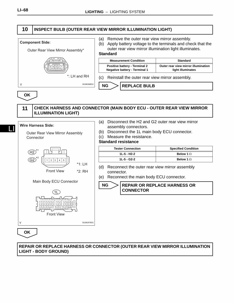
(a) Remove the outer rear view mirror assembly.(b) Apply battery voltage to the terminals and check that the
outer rear view mirror illumination light illuminates.Standard
(c) Reinstall the outer rear view mirror assembly.
NG
OK
(a) Disconnect the H2 and G2 outer rear view mirror assembly connectors.
(b) Disconnect the 1L main body ECU connector.(c) Measure the resistance.Standard resistance
(d) Reconnect the outer rear view mirror assembly connector.
(e) Reconnect the main body ECU connector.
NG
OK
10 INSPECT BULB (OUTER REAR VIEW MIRROR ILLUMINATION LIGHT)
12345
Component Side:
Outer Rear View Mirror Assembly*
*: LH and RH
B138196E01
Measurement Condition Standard
Positive battery - Terminal 2Negative battery - Terminal 1
Outer rear view mirror illumination light illuminates
REPLACE BULB
11 CHECK HARNESS AND CONNECTOR (MAIN BODY ECU - OUTER REAR VIEW MIRROR ILLUMINATION LIGHT)
1 2 3 4 5
1
13
2
14
3
15
4
16
5
17
6
18
9
21
10
22
11
23
12
24
7
19
8
20
1L
H2
G2
Wire Harness Side:
Front View
*1: LH
*2: RH
Front View
Outer Rear View Mirror Assembly
Connector
*1
*2
Main Body ECU Connector
B138197E01
Tester Connection Specified Condition
1L-5 - H2-2 Below 1 Ω
1L-5 - G2-2 Below 1 Ω
REPAIR OR REPLACE HARNESS OR CONNECTOR
REPAIR OR REPLACE HARNESS OR CONNECTOR (OUTER REAR VIEW MIRROR ILLUMINATION LIGHT - BODY GROUND)
LIGHTING – HEADLIGHT ASSEMBLY LI–67
I
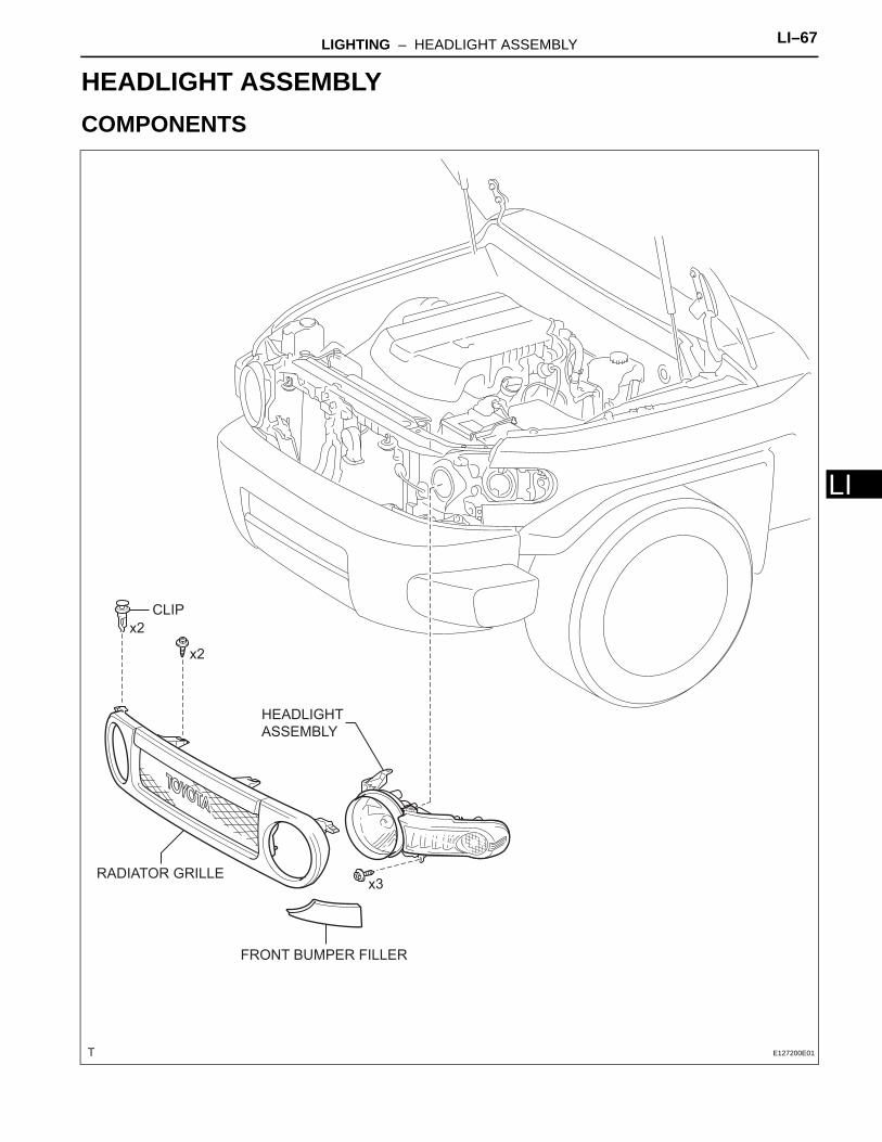
LBODY ELECTRICALLIGHTINGHEADLIGHT ASSEMBLYCOMPONENTS
FRONT BUMPER FILLER
HEADLIGHT
ASSEMBLY
RADIATOR GRILLE
CLIP
x2
x2
x3
E127200E01
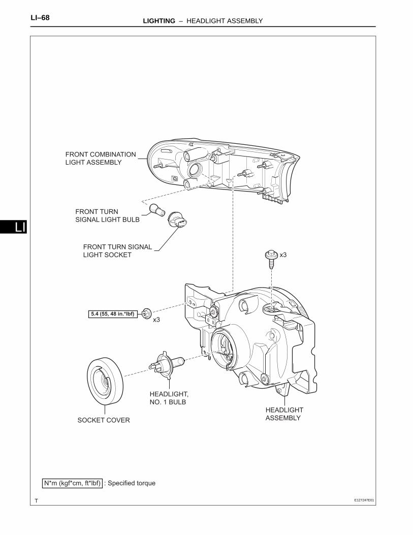
LI–68 LIGHTING – HEADLIGHT ASSEMBLY
LI
FRONT TURNSIGNAL LIGHT BULB
HEADLIGHT
ASSEMBLY
HEADLIGHT,
NO. 1 BULB
FRONT TURN SIGNAL
LIGHT SOCKET
x3
SOCKET COVER
x3
FRONT COMBINATION
LIGHT ASSEMBLY
N*m (kgf*cm, ft*lbf) : Specified torque
5.4 (55, 48 in.*lbf)
E127247E01
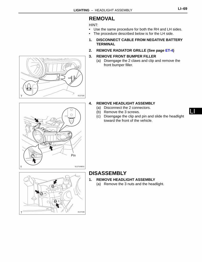
LIGHTING – HEADLIGHT ASSEMBLY LI–69
I
LREMOVALHINT:• Use the same procedure for both the RH and LH sides.• The procedure described below is for the LH side.
1. DISCONNECT CABLE FROM NEGATIVE BATTERY TERMINAL
2. REMOVE RADIATOR GRILLE (See page ET-4)3. REMOVE FRONT BUMPER FILLER
(a) Disengage the 2 claws and clip and remove the front bumper filler.
4. REMOVE HEADLIGHT ASSEMBLY(a) Disconnect the 2 connectors.(b) Remove the 3 screws.(c) Disengage the clip and pin and slide the headlight
toward the front of the vehicle.
DISASSEMBLY1. REMOVE HEADLIGHT ASSEMBLY
(a) Remove the 3 nuts and the headlight.
E127192
Pin
E127193E01
E127239
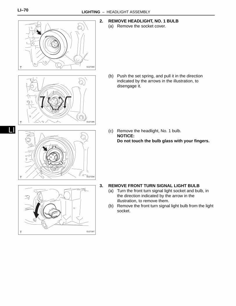
LI–70 LIGHTING – HEADLIGHT ASSEMBLY
LI
2. REMOVE HEADLIGHT, NO. 1 BULB(a) Remove the socket cover.
(b) Push the set spring, and pull it in the direction indicated by the arrows in the illustration, to disengage it.
(c) Remove the headlight, No. 1 bulb.NOTICE:Do not touch the bulb glass with your fingers.
3. REMOVE FRONT TURN SIGNAL LIGHT BULB(a) Turn the front turn signal light socket and bulb, in
the direction indicated by the arrow in the illustration, to remove them.
(b) Remove the front turn signal light bulb from the light socket.
E127194
E127195
E127234
E127197
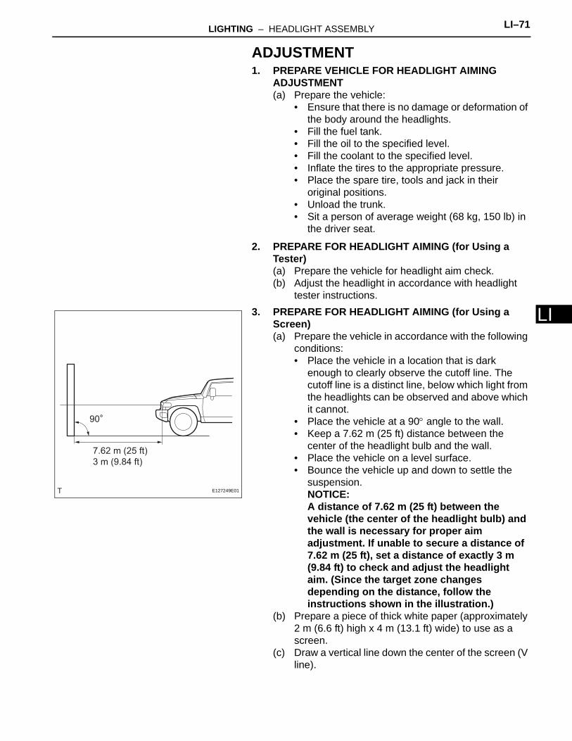
LIGHTING – HEADLIGHT ASSEMBLY LI–71
I
LADJUSTMENT1. PREPARE VEHICLE FOR HEADLIGHT AIMING
ADJUSTMENT(a) Prepare the vehicle:
• Ensure that there is no damage or deformation of the body around the headlights.
• Fill the fuel tank.• Fill the oil to the specified level.• Fill the coolant to the specified level.• Inflate the tires to the appropriate pressure.• Place the spare tire, tools and jack in their
original positions.• Unload the trunk.• Sit a person of average weight (68 kg, 150 lb) in
the driver seat.
2. PREPARE FOR HEADLIGHT AIMING (for Using a Tester)(a) Prepare the vehicle for headlight aim check.(b) Adjust the headlight in accordance with headlight
tester instructions.3. PREPARE FOR HEADLIGHT AIMING (for Using a
Screen)(a) Prepare the vehicle in accordance with the following
conditions:• Place the vehicle in a location that is dark
enough to clearly observe the cutoff line. The cutoff line is a distinct line, below which light from the headlights can be observed and above which it cannot.
• Place the vehicle at a 90° angle to the wall.• Keep a 7.62 m (25 ft) distance between the
center of the headlight bulb and the wall.• Place the vehicle on a level surface.• Bounce the vehicle up and down to settle the
suspension.NOTICE:A distance of 7.62 m (25 ft) between the vehicle (the center of the headlight bulb) and the wall is necessary for proper aim adjustment. If unable to secure a distance of 7.62 m (25 ft), set a distance of exactly 3 m (9.84 ft) to check and adjust the headlight aim. (Since the target zone changes depending on the distance, follow the instructions shown in the illustration.)
(b) Prepare a piece of thick white paper (approximately 2 m (6.6 ft) high x 4 m (13.1 ft) wide) to use as a screen.
(c) Draw a vertical line down the center of the screen (V line).
90
7.62 m (25 ft)
3 m (9.84 ft)
E127249E01
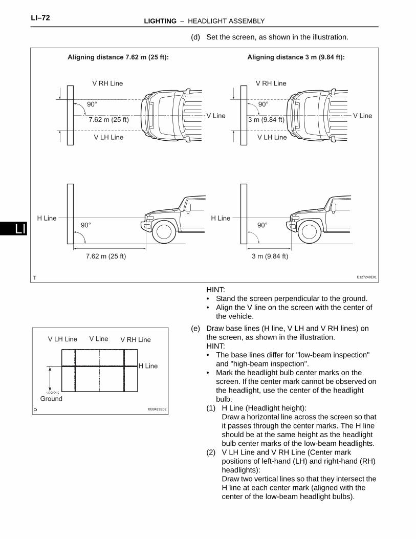
LI–72 LIGHTING – HEADLIGHT ASSEMBLY
LI
(d) Set the screen, as shown in the illustration.
HINT:• Stand the screen perpendicular to the ground.• Align the V line on the screen with the center of
the vehicle.(e) Draw base lines (H line, V LH and V RH lines) on
the screen, as shown in the illustration.HINT:• The base lines differ for "low-beam inspection"
and "high-beam inspection".• Mark the headlight bulb center marks on the
screen. If the center mark cannot be observed on the headlight, use the center of the headlight bulb.
(1) H Line (Headlight height):Draw a horizontal line across the screen so that it passes through the center marks. The H line should be at the same height as the headlight bulb center marks of the low-beam headlights.
(2) V LH Line and V RH Line (Center mark positions of left-hand (LH) and right-hand (RH) headlights):Draw two vertical lines so that they intersect the H line at each center mark (aligned with the center of the low-beam headlight bulbs).
Aligning distance 7.62 m (25 ft): Aligning distance 3 m (9.84 ft):
V RH Line
90°
7.62 m (25 ft)
V LH Line
V Line
V RH Line
90°
3 m (9.84 ft)
V LH Line
V Line
H Line90°
7.62 m (25 ft)
H Line90°
3 m (9.84 ft)
E127248E01
V LH Line V Line V RH Line
H Line
Ground
I033423E02
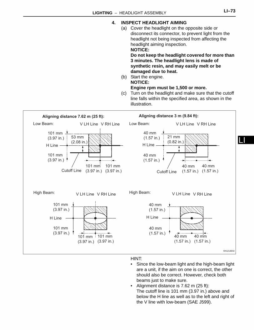
LIGHTING – HEADLIGHT ASSEMBLY LI–73
I
L4. INSPECT HEADLIGHT AIMING(a) Cover the headlight on the opposite side or
disconnect its connector, to prevent light from the headlight not being inspected from affecting the headlight aiming inspection.NOTICE:Do not keep the headlight covered for more than 3 minutes. The headlight lens is made of synthetic resin, and may easily melt or be damaged due to heat.
(b) Start the engine.NOTICE:Engine rpm must be 1,500 or more.
(c) Turn on the headlight and make sure that the cutoff line falls within the specified area, as shown in the illustration.
HINT:• Since the low-beam light and the high-beam light
are a unit, if the aim on one is correct, the other should also be correct. However, check both beams just to make sure.
• Alignment distance is 7.62 m (25 ft):The cutoff line is 101 mm (3.97 in.) above and below the H line as well as to the left and right of the V line with low-beam (SAE J599).
Aligning distance 7.62 m (25 ft): Aligning distance 3 m (9.84 ft):
H Line
H Line H Line
V RH LineV LH LineLow Beam:
High Beam:
V RH LineV LH LineLow Beam:
High Beam:
40 mm
(1.57 in.)101 mm
(3.97 in.)
101 mm
(3.97 in.)40 mm
(1.57 in.)
53 mm
(2.08 in.)
21 mm
(0.82 in.)
40 mm
(1.57 in.)40 mm
(1.57 in.)
101 mm
(3.97 in.)
101 mm
(3.97 in.) Cutoff LineCutoff Line
H Line
40 mm
(1.57 in.)
101 mm
(3.97 in.)
101 mm
(3.97 in.)40 mm
(1.57 in.)40 mm
(1.57 in.)
40 mm
(1.57 in.)
101 mm
(3.97 in.)101 mm
(3.97 in.)
V RH LineV LH Line V RH LineV LH Line
I041213E02
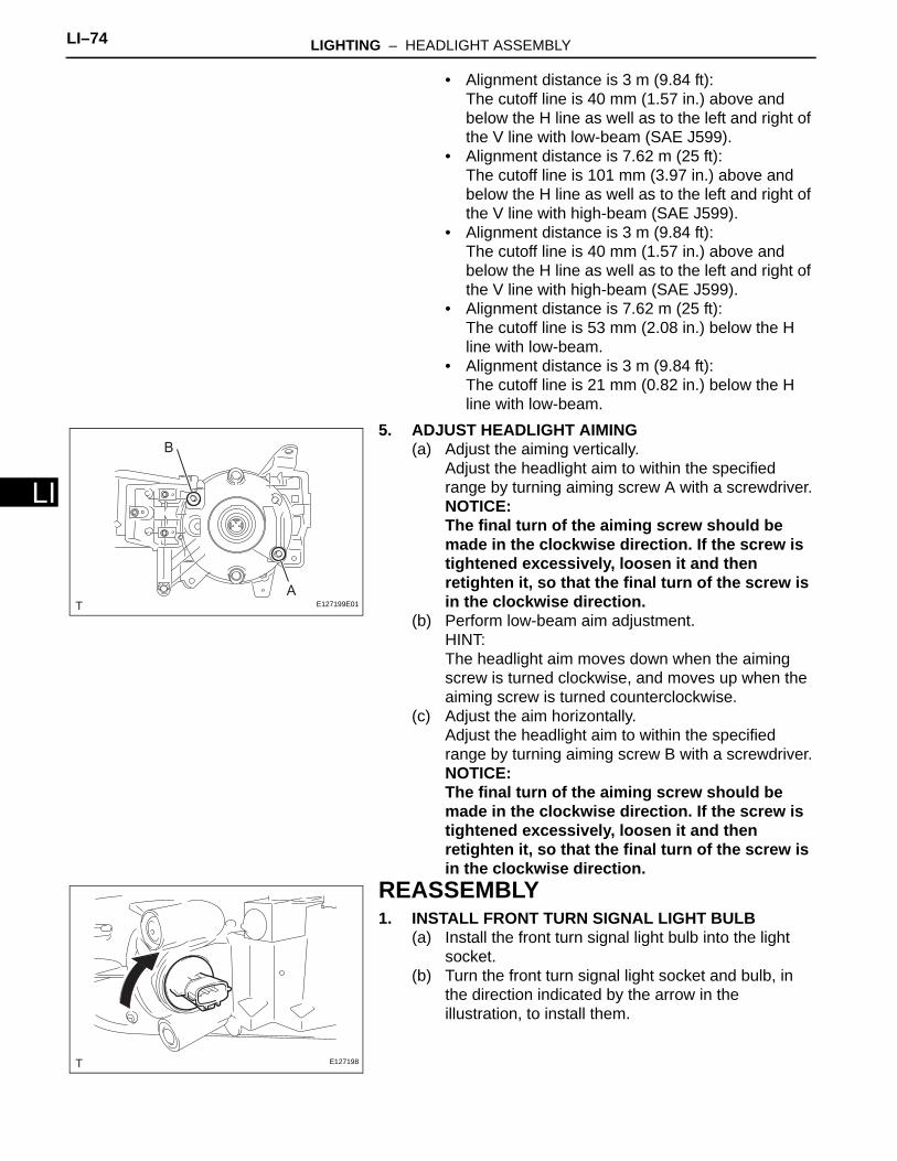
LI–74 LIGHTING – HEADLIGHT ASSEMBLY
LI
• Alignment distance is 3 m (9.84 ft):The cutoff line is 40 mm (1.57 in.) above and below the H line as well as to the left and right of the V line with low-beam (SAE J599).
• Alignment distance is 7.62 m (25 ft):The cutoff line is 101 mm (3.97 in.) above and below the H line as well as to the left and right of the V line with high-beam (SAE J599).
• Alignment distance is 3 m (9.84 ft):The cutoff line is 40 mm (1.57 in.) above and below the H line as well as to the left and right of the V line with high-beam (SAE J599).
• Alignment distance is 7.62 m (25 ft):The cutoff line is 53 mm (2.08 in.) below the H line with low-beam.
• Alignment distance is 3 m (9.84 ft):The cutoff line is 21 mm (0.82 in.) below the H line with low-beam.
5. ADJUST HEADLIGHT AIMING(a) Adjust the aiming vertically.
Adjust the headlight aim to within the specified range by turning aiming screw A with a screwdriver.NOTICE:The final turn of the aiming screw should be made in the clockwise direction. If the screw is tightened excessively, loosen it and then retighten it, so that the final turn of the screw is in the clockwise direction.
(b) Perform low-beam aim adjustment.HINT:The headlight aim moves down when the aiming screw is turned clockwise, and moves up when the aiming screw is turned counterclockwise.
(c) Adjust the aim horizontally.Adjust the headlight aim to within the specified range by turning aiming screw B with a screwdriver.NOTICE:The final turn of the aiming screw should be made in the clockwise direction. If the screw is tightened excessively, loosen it and then retighten it, so that the final turn of the screw is in the clockwise direction.
REASSEMBLY1. INSTALL FRONT TURN SIGNAL LIGHT BULB
(a) Install the front turn signal light bulb into the light socket.
(b) Turn the front turn signal light socket and bulb, in the direction indicated by the arrow in the illustration, to install them.
A
B
E127199E01
E127198
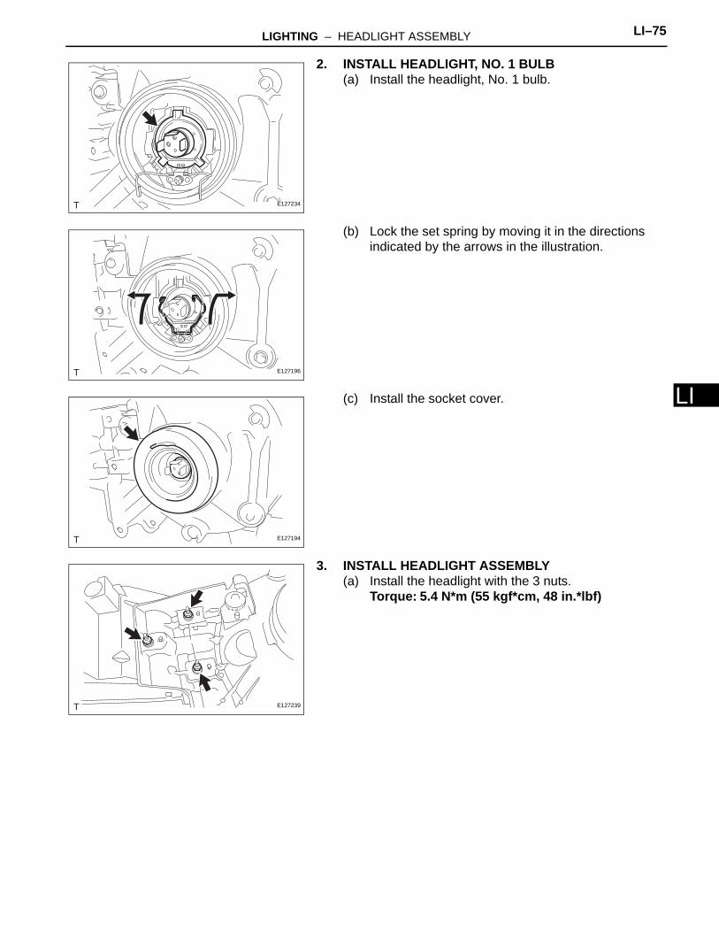
LIGHTING – HEADLIGHT ASSEMBLY LI–75
I
L2. INSTALL HEADLIGHT, NO. 1 BULB(a) Install the headlight, No. 1 bulb.
(b) Lock the set spring by moving it in the directions indicated by the arrows in the illustration.
(c) Install the socket cover.
3. INSTALL HEADLIGHT ASSEMBLY(a) Install the headlight with the 3 nuts.
Torque: 5.4 N*m (55 kgf*cm, 48 in.*lbf)
E127234
E127196
E127194
E127239
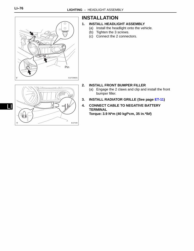
LI–76 LIGHTING – HEADLIGHT ASSEMBLY
LI
INSTALLATION1. INSTALL HEADLIGHT ASSEMBLY
(a) Install the headlight onto the vehicle.(b) Tighten the 3 screws.(c) Connect the 2 connectors.
2. INSTALL FRONT BUMPER FILLER(a) Engage the 2 claws and clip and install the front
bumper filler.
3. INSTALL RADIATOR GRILLE (See page ET-11)4. CONNECT CABLE TO NEGATIVE BATTERY
TERMINALTorque: 3.9 N*m (40 kgf*cm, 35 in.*lbf)
Pin
E127193E01
E127192
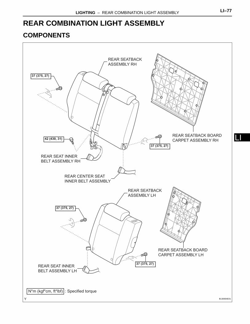
LIGHTING – REAR COMBINATION LIGHT ASSEMBLY LI–77
I
LBODY ELECTRICALLIGHTINGREAR COMBINATION LIGHT ASSEMBLYCOMPONENTS
REAR SEATBACK
ASSEMBLY LH
REAR SEATBACK
ASSEMBLY RH
REAR SEATBACK BOARD
CARPET ASSEMBLY LH
REAR SEATBACK BOARD
CARPET ASSEMBLY RH
37 (375, 27)
N*m (kgf*cm, ft*lbf) : Specified torque
37 (375, 27)
37 (375, 27)
42 (430, 31)
37 (375, 27)
REAR SEAT INNER
BELT ASSEMBLY RH
REAR CENTER SEAT
INNER BELT ASSEMBLY
REAR SEAT INNER
BELT ASSEMBLY LH
B130654E01
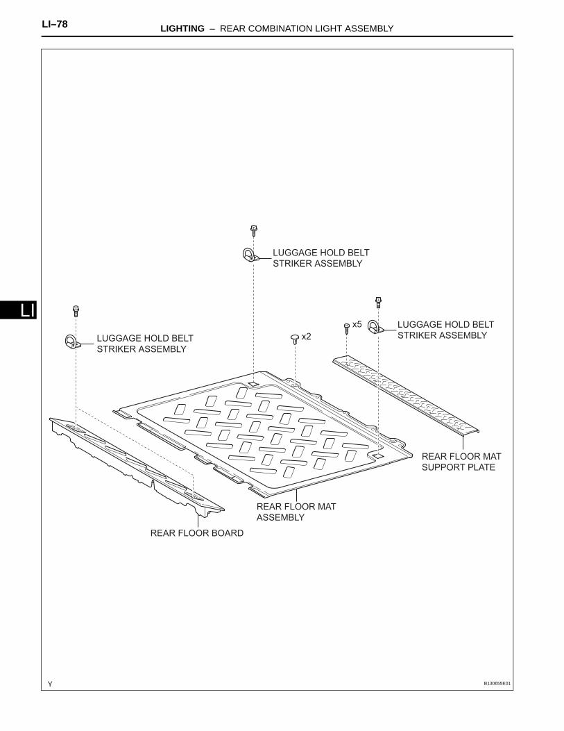
LI–78 LIGHTING – REAR COMBINATION LIGHT ASSEMBLY
LI
REAR FLOOR BOARD
REAR FLOOR MAT
ASSEMBLY
REAR FLOOR MAT
SUPPORT PLATE
LUGGAGE HOLD BELT
STRIKER ASSEMBLYLUGGAGE HOLD BELT
STRIKER ASSEMBLY
x2
x5
LUGGAGE HOLD BELT
STRIKER ASSEMBLY
B130655E01
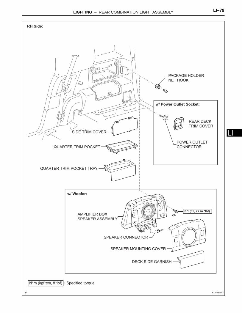
LIGHTING – REAR COMBINATION LIGHT ASSEMBLY LI–79
I
Lx4
w/ Woofer:
AMPLIFIER BOX
SPEAKER ASSEMBLY
DECK SIDE GARNISH
PACKAGE HOLDER
NET HOOK
QUARTER TRIM POCKET
QUARTER TRIM POCKET TRAY
SIDE TRIM COVER
SPEAKER MOUNTING COVER
N*m (kgf*cm, ft*lbf) : Specified torque
8.1 (85, 72 in.*lbf)
REAR DECK
TRIM COVER
POWER OUTLET
CONNECTOR
w/ Power Outlet Socket:
RH Side:
SPEAKER CONNECTOR
B134989E02
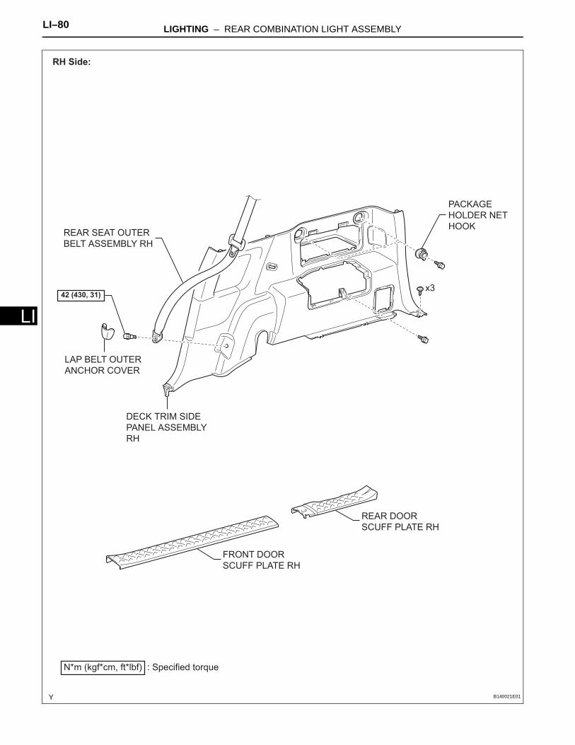
LI–80 LIGHTING – REAR COMBINATION LIGHT ASSEMBLY
LI
DECK TRIM SIDE
PANEL ASSEMBLY
RH
FRONT DOOR
SCUFF PLATE RH
LAP BELT OUTER
ANCHOR COVER
PACKAGE
HOLDER NET
HOOK
REAR DOOR
SCUFF PLATE RH
REAR SEAT OUTER
BELT ASSEMBLY RH
N*m (kgf*cm, ft*lbf) : Specified torque
42 (430, 31)x3
RH Side:
B140021E01

LIGHTING – REAR COMBINATION LIGHT ASSEMBLY LI–81
I
LDECK TRIM SIDE PANEL
ASSEMBLY LH
FRONT DOOR
SCUFF PLATE LH
LAP BELT OUTER
ANCHOR COVER
REAR DOOR
SCUFF PLATE LH
REAR SEAT OUTER BELT
ASSEMBLY LH
PACKAGE HOLDER
NET HOOK
N*m (kgf*cm, ft*lbf) : Specified torque
42 (430, 31)
x3
LH Side:
B140020E01
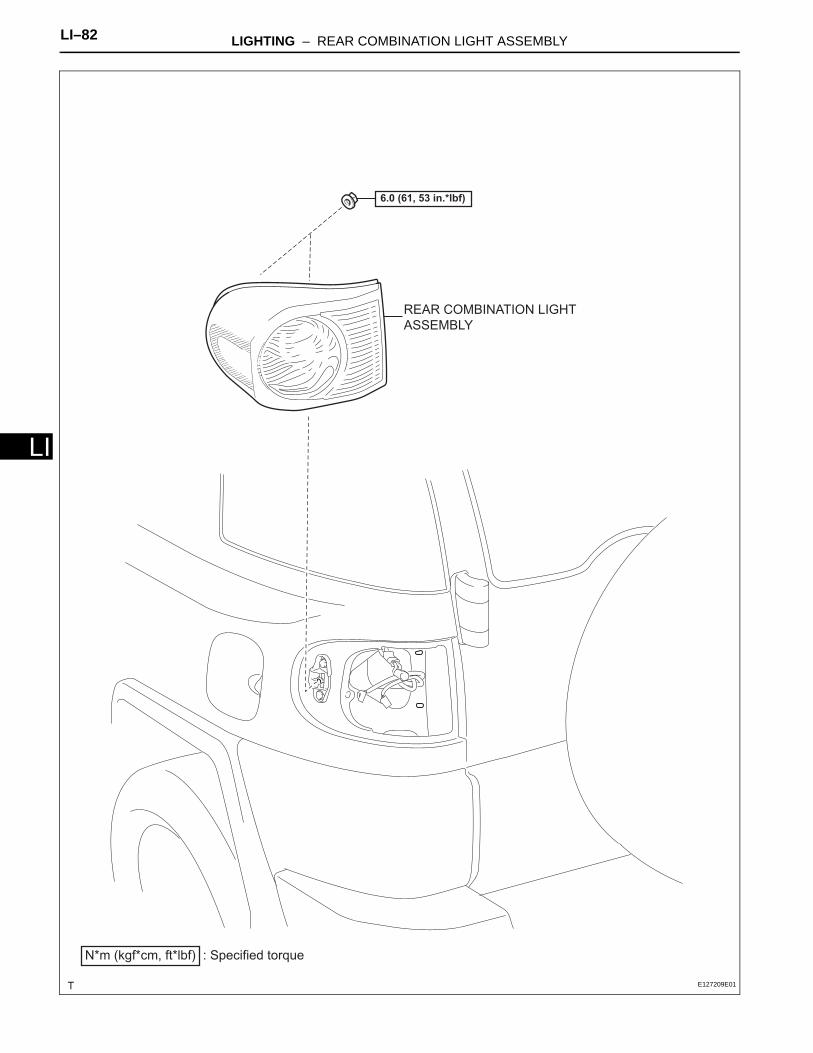
LI–82 LIGHTING – REAR COMBINATION LIGHT ASSEMBLY
LI
REAR COMBINATION LIGHT
ASSEMBLY
N*m (kgf*cm, ft*lbf) : Specified torque
6.0 (61, 53 in.*lbf)
E127209E01
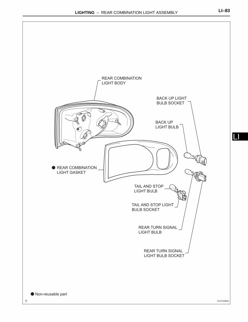
LIGHTING – REAR COMBINATION LIGHT ASSEMBLY LI–83
I
LBACK UP
LIGHT BULB
REAR TURN SIGNAL
LIGHT BULB
TAIL AND STOP
LIGHT BULB
REAR TURN SIGNAL
LIGHT BULB SOCKET
TAIL AND STOP LIGHT
BULB SOCKET
BACK UP LIGHT
BULB SOCKET
REAR COMBINATION
LIGHT BODY
Non-reusable part
REAR COMBINATION
LIGHT GASKET
E127210E01
LI–84 LIGHTING – REAR COMBINATION LIGHT ASSEMBLY
LI
REMOVALHINT:• Use the same procedure for both the RH and LH sides,
unless otherwise specified.• The procedure described below is for the LH side.
1. DISCONNECT CABLE FROM NEGATIVE BATTERY TERMINAL
2. REMOVE REAR SEATBACK BOARD CARPET ASSEMBLY RH (See page SE-43)
3. REMOVE REAR SEATBACK ASSEMBLY RH (See page SE-43)
4. REMOVE REAR SEATBACK BOARD CARPET ASSEMBLY LH (See page SE-29)
5. REMOVE REAR SEATBACK ASSEMBLY LH (See page SE-29)
6. REMOVE REAR FLOOR BOARD (See page IR-13)7. REMOVE REAR FLOOR MAT SUPPORT PLATE (See
page IR-14)8. REMOVE REAR FLOOR MAT ASSEMBLY (See page
IR-15)9. REMOVE LUGGAGE HOLD BELT STRIKER
ASSEMBLY (See page IR-14)10. REMOVE FRONT DOOR SCUFF PLATE RH (See page
IR-15)11. REMOVE FRONT DOOR SCUFF PLATE LH (See page
IR-15)12. REMOVE REAR DOOR SCUFF PLATE RH (See page
IR-15)13. REMOVE REAR DOOR SCUFF PLATE LH (See page
IR-15)14. REMOVE FRONT DOOR OPENING TRIM
WEATHERSTRIP RH (See page IR-16)15. REMOVE FRONT DOOR OPENING TRIM
WEATHERSTRIP LH (See page IR-16)16. REMOVE DECK SIDE GARNISH (w/ Woofer) (See
page IR-18)17. REMOVE SPEAKER MOUNTING COVER (w/ Woofer)
(See page AV-90)18. REMOVE BOX SPEAKER ASSEMBLY (w/ Woofer)
(See page AV-90)19. REMOVE PACKAGE HOLDER NET HOOK (See page
IR-18)20. REMOVE QUARTER TRIM POCKET TRAY (w/o
Woofer) (See page IR-19)
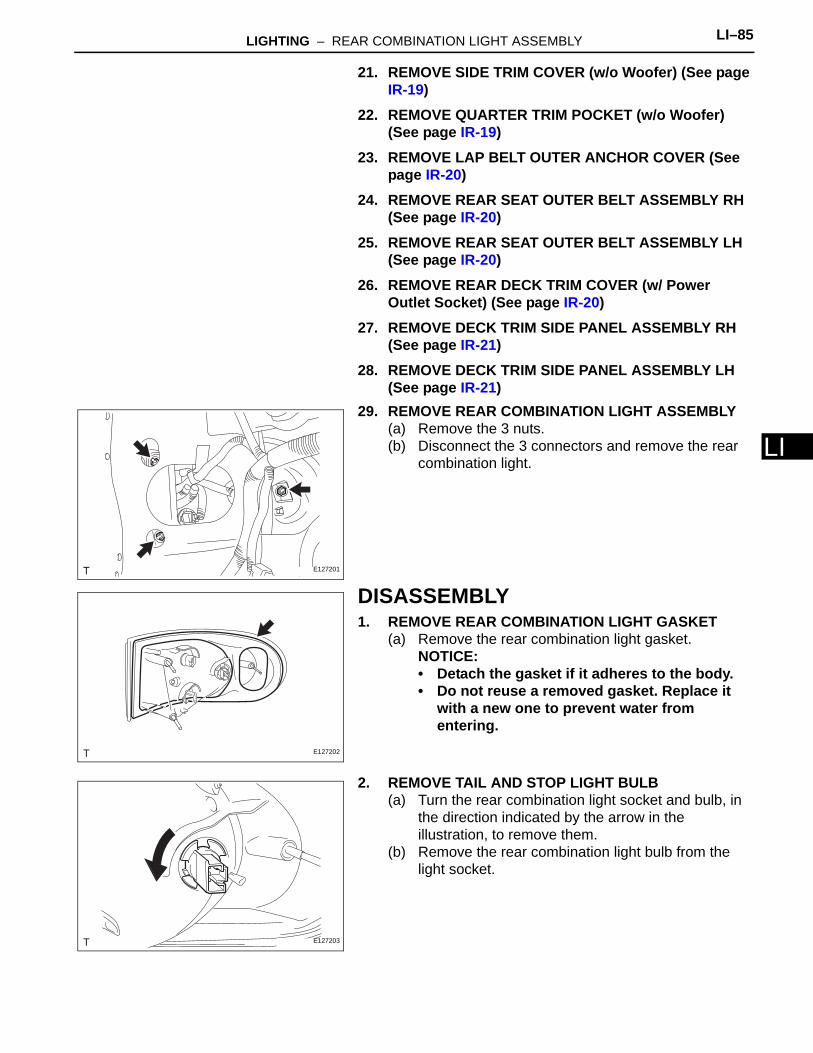
LIGHTING – REAR COMBINATION LIGHT ASSEMBLY LI–85
I
L21. REMOVE SIDE TRIM COVER (w/o Woofer) (See page IR-19)
22. REMOVE QUARTER TRIM POCKET (w/o Woofer) (See page IR-19)
23. REMOVE LAP BELT OUTER ANCHOR COVER (See page IR-20)
24. REMOVE REAR SEAT OUTER BELT ASSEMBLY RH (See page IR-20)
25. REMOVE REAR SEAT OUTER BELT ASSEMBLY LH (See page IR-20)
26. REMOVE REAR DECK TRIM COVER (w/ Power Outlet Socket) (See page IR-20)
27. REMOVE DECK TRIM SIDE PANEL ASSEMBLY RH (See page IR-21)
28. REMOVE DECK TRIM SIDE PANEL ASSEMBLY LH (See page IR-21)
29. REMOVE REAR COMBINATION LIGHT ASSEMBLY(a) Remove the 3 nuts.(b) Disconnect the 3 connectors and remove the rear
combination light.
DISASSEMBLY1. REMOVE REAR COMBINATION LIGHT GASKET
(a) Remove the rear combination light gasket.NOTICE:• Detach the gasket if it adheres to the body.• Do not reuse a removed gasket. Replace it
with a new one to prevent water from entering.
2. REMOVE TAIL AND STOP LIGHT BULB(a) Turn the rear combination light socket and bulb, in
the direction indicated by the arrow in the illustration, to remove them.
(b) Remove the rear combination light bulb from the light socket.
E127201
E127202
E127203
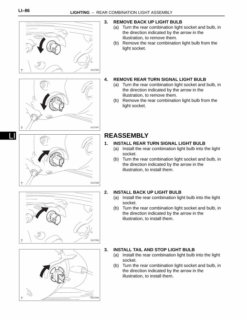
LI–86 LIGHTING – REAR COMBINATION LIGHT ASSEMBLY
LI
3. REMOVE BACK UP LIGHT BULB(a) Turn the rear combination light socket and bulb, in
the direction indicated by the arrow in the illustration, to remove them.
(b) Remove the rear combination light bulb from the light socket.
4. REMOVE REAR TURN SIGNAL LIGHT BULB(a) Turn the rear combination light socket and bulb, in
the direction indicated by the arrow in the illustration, to remove them.
(b) Remove the rear combination light bulb from the light socket.
REASSEMBLY1. INSTALL REAR TURN SIGNAL LIGHT BULB
(a) Install the rear combination light bulb into the light socket.
(b) Turn the rear combination light socket and bulb, in the direction indicated by the arrow in the illustration, to install them.
2. INSTALL BACK UP LIGHT BULB(a) Install the rear combination light bulb into the light
socket.(b) Turn the rear combination light socket and bulb, in
the direction indicated by the arrow in the illustration, to install them.
3. INSTALL TAIL AND STOP LIGHT BULB(a) Install the rear combination light bulb into the light
socket.(b) Turn the rear combination light socket and bulb, in
the direction indicated by the arrow in the illustration, to install them.
E127205
E127207
E127208
E127206
E127204
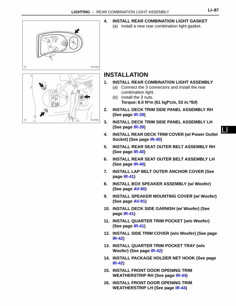
LIGHTING – REAR COMBINATION LIGHT ASSEMBLY LI–87
I
L4. INSTALL REAR COMBINATION LIGHT GASKET(a) Install a new rear combination light gasket.
INSTALLATION1. INSTALL REAR COMBINATION LIGHT ASSEMBLY
(a) Connect the 3 connectors and install the rear combination light.
(b) Install the 3 nuts.Torque: 6.0 N*m (61 kgf*cm, 53 in.*lbf)
2. INSTALL DECK TRIM SIDE PANEL ASSEMBLY RH (See page IR-39)
3. INSTALL DECK TRIM SIDE PANEL ASSEMBLY LH (See page IR-39)
4. INSTALL REAR DECK TRIM COVER (w/ Power Outlet Socket) (See page IR-40)
5. INSTALL REAR SEAT OUTER BELT ASSEMBLY RH (See page IR-40)
6. INSTALL REAR SEAT OUTER BELT ASSEMBLY LH (See page IR-40)
7. INSTALL LAP BELT OUTER ANCHOR COVER (See page IR-41)
8. INSTALL BOX SPEAKER ASSEMBLY (w/ Woofer) (See page AV-90)
9. INSTALL SPEAKER MOUNTING COVER (w/ Woofer) (See page AV-91)
10. INSTALL DECK SIDE GARNISH (w/ Woofer) (See page IR-41)
11. INSTALL QUARTER TRIM POCKET (w/o Woofer) (See page IR-41)
12. INSTALL SIDE TRIM COVER (w/o Woofer) (See page IR-42)
13. INSTALL QUARTER TRIM POCKET TRAY (w/o Woofer) (See page IR-42)
14. INSTALL PACKAGE HOLDER NET HOOK (See page IR-42)
15. INSTALL FRONT DOOR OPENING TRIM WEATHERSTRIP RH (See page IR-44)
16. INSTALL FRONT DOOR OPENING TRIM WEATHERSTRIP LH (See page IR-44)
E127202
E127201
LI–88 LIGHTING – REAR COMBINATION LIGHT ASSEMBLY
LI
17. INSTALL REAR DOOR SCUFF PLATE RH (See page IR-45)
18. INSTALL REAR DOOR SCUFF PLATE LH (See page IR-45)
19. INSTALL FRONT DOOR SCUFF PLATE RH (See page IR-45)
20. INSTALL FRONT DOOR SCUFF PLATE LH (See page IR-45)
21. INSTALL LUGGAGE HOLD BELT STRIKER ASSEMBLY (See page IR-46)
22. INSTALL REAR FLOOR MAT ASSEMBLY (See page IR-46)
23. INSTALL REAR FLOOR MAT SUPPORT PLATE (See page IR-46)
24. INSTALL REAR FLOOR BOARD (See page IR-47)25. INSTALL REAR SEATBACK ASSEMBLY RH (See
page SE-54)26. INSTALL REAR SEATBACK BOARD CARPET
ASSEMBLY RH (See page SE-54)27. INSTALL REAR SEATBACK ASSEMBLY LH (See
page SE-38)28. INSTALL REAR SEATBACK BOARD CARPET
ASSEMBLY LH (See page SE-38)29. CONNECT CABLE TO NEGATIVE BATTERY
TERMINALTorque: 3.9 N*m (40 kgf*cm, 35 in.*lbf)
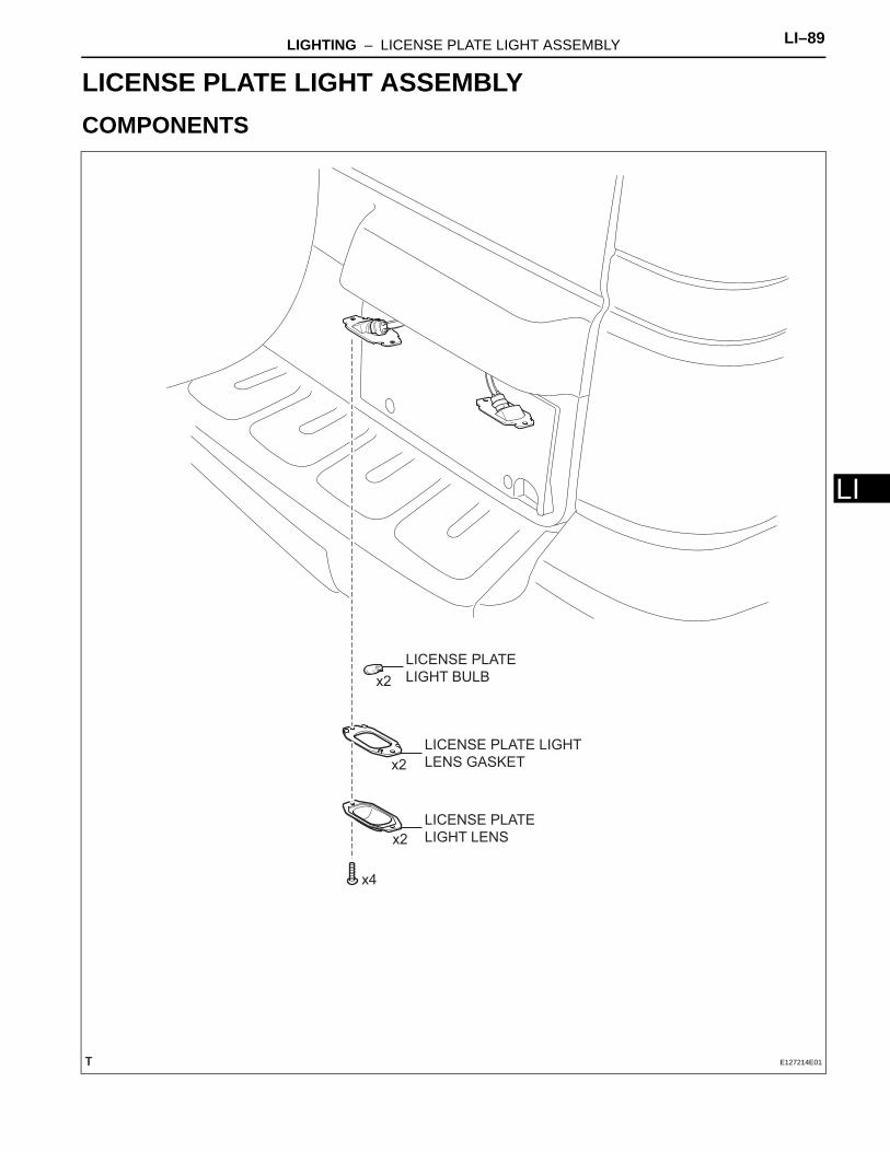
LIGHTING – LICENSE PLATE LIGHT ASSEMBLY LI–89
I
LBODY ELECTRICALLIGHTINGLICENSE PLATE LIGHT ASSEMBLYCOMPONENTS
LICENSE PLATE
LIGHT BULB
LICENSE PLATE
LIGHT LENS
LICENSE PLATE LIGHT
LENS GASKET
x2
x2
x2
x4
E127214E01
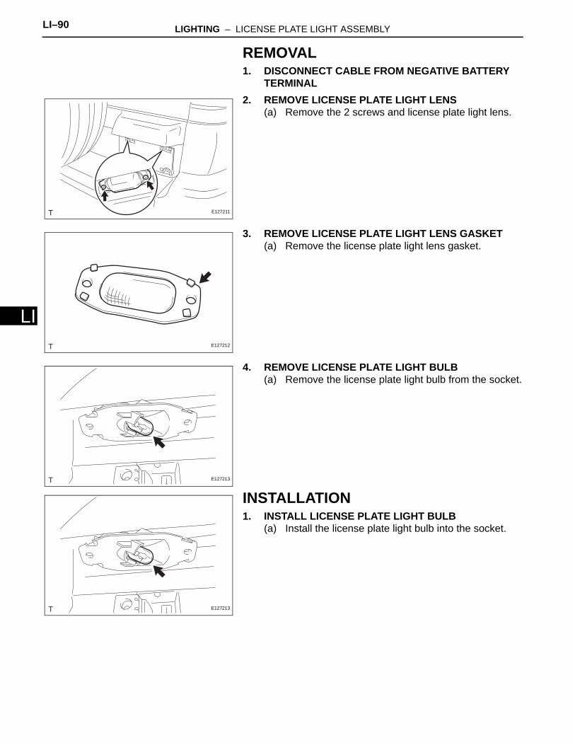
LI–90 LIGHTING – LICENSE PLATE LIGHT ASSEMBLY
LI
REMOVAL1. DISCONNECT CABLE FROM NEGATIVE BATTERY
TERMINAL2. REMOVE LICENSE PLATE LIGHT LENS
(a) Remove the 2 screws and license plate light lens.
3. REMOVE LICENSE PLATE LIGHT LENS GASKET(a) Remove the license plate light lens gasket.
4. REMOVE LICENSE PLATE LIGHT BULB(a) Remove the license plate light bulb from the socket.
INSTALLATION1. INSTALL LICENSE PLATE LIGHT BULB
(a) Install the license plate light bulb into the socket.
E127211
E127212
E127213
E127213

LIGHTING – LICENSE PLATE LIGHT ASSEMBLY LI–91
I
L2. INSTALL LICENSE PLATE LIGHT LENS GASKET(a) Install the license plate light lens gasket onto the
license plate light lens.
3. INSTALL LICENSE PLATE LIGHT LENS(a) Install the license plate light lens with the 2 screws.
4. CONNECT CABLE TO NEGATIVE BATTERY TERMINALTorque: 3.9 N*m (40 kgf*cm, 35 in.*lbf)
E127212
E127211
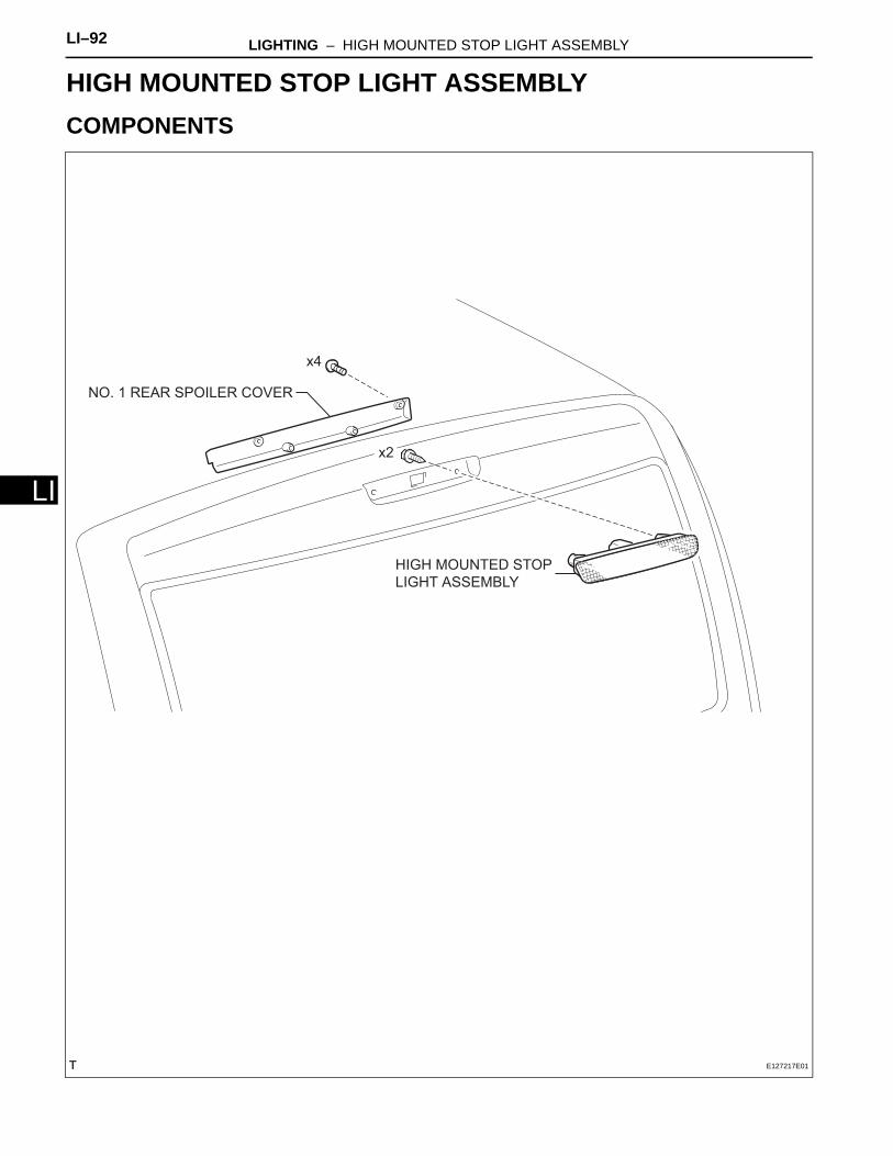
LI–92 LIGHTING – HIGH MOUNTED STOP LIGHT ASSEMBLY
LI
BODY ELECTRICALLIGHTINGHIGH MOUNTED STOP LIGHT ASSEMBLYCOMPONENTS
HIGH MOUNTED STOP
LIGHT ASSEMBLY
NO. 1 REAR SPOILER COVER
x4
x2
E127217E01
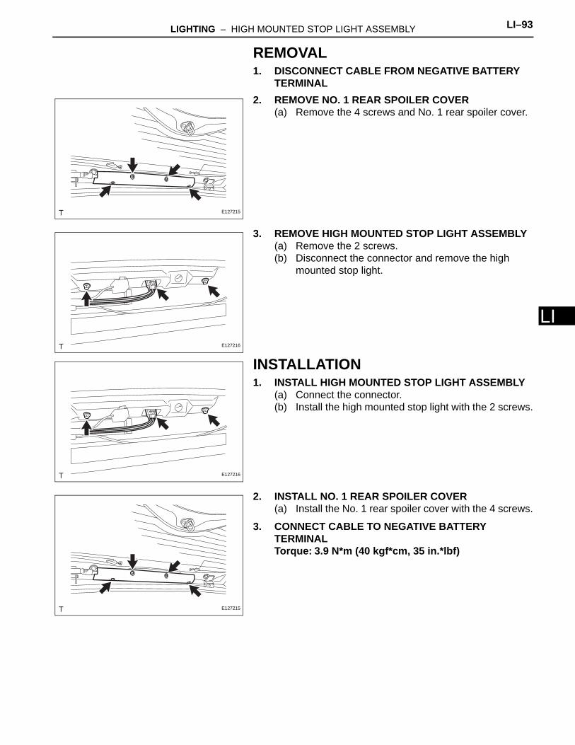
LIGHTING – HIGH MOUNTED STOP LIGHT ASSEMBLY LI–93
I
LREMOVAL1. DISCONNECT CABLE FROM NEGATIVE BATTERY
TERMINAL2. REMOVE NO. 1 REAR SPOILER COVER
(a) Remove the 4 screws and No. 1 rear spoiler cover.
3. REMOVE HIGH MOUNTED STOP LIGHT ASSEMBLY(a) Remove the 2 screws.(b) Disconnect the connector and remove the high
mounted stop light.
INSTALLATION1. INSTALL HIGH MOUNTED STOP LIGHT ASSEMBLY
(a) Connect the connector.(b) Install the high mounted stop light with the 2 screws.
2. INSTALL NO. 1 REAR SPOILER COVER(a) Install the No. 1 rear spoiler cover with the 4 screws.
3. CONNECT CABLE TO NEGATIVE BATTERY TERMINALTorque: 3.9 N*m (40 kgf*cm, 35 in.*lbf)
E127215
E127216
E127216
E127215
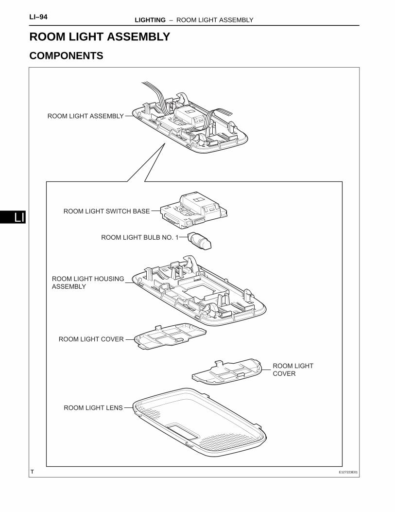
LI–94 LIGHTING – ROOM LIGHT ASSEMBLY
LI
BODY ELECTRICALLIGHTINGROOM LIGHT ASSEMBLYCOMPONENTS
ROOM LIGHT ASSEMBLY
ROOM LIGHT SWITCH BASE
ROOM LIGHT BULB NO. 1
ROOM LIGHT HOUSING
ASSEMBLY
ROOM LIGHT COVER
ROOM LIGHT LENS
ROOM LIGHT
COVER
E127223E01
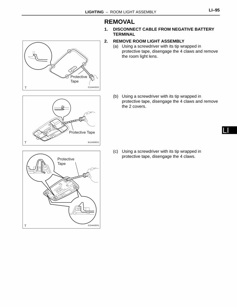
LIGHTING – ROOM LIGHT ASSEMBLY LI–95
I
LREMOVAL1. DISCONNECT CABLE FROM NEGATIVE BATTERY
TERMINAL2. REMOVE ROOM LIGHT ASSEMBLY
(a) Using a screwdriver with its tip wrapped in protective tape, disengage the 4 claws and remove the room light lens.
(b) Using a screwdriver with its tip wrapped in protective tape, disengage the 4 claws and remove the 2 covers.
(c) Using a screwdriver with its tip wrapped in protective tape, disengage the 4 claws.
Protective
Tape
E114441E01
Protective Tape
B124365E01
Protective
Tape
E114442E01
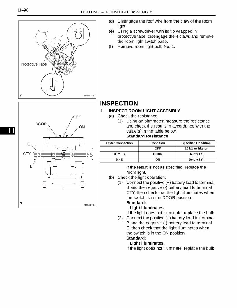
LI–96 LIGHTING – ROOM LIGHT ASSEMBLY
LI
(d) Disengage the roof wire from the claw of the room light.
(e) Using a screwdriver with its tip wrapped in protective tape, disengage the 4 claws and remove the room light switch base.
(f) Remove room light bulb No. 1.
INSPECTION1. INSPECT ROOM LIGHT ASSEMBLY
(a) Check the resistance.(1) Using an ohmmeter, measure the resistance
and check the results in accordance with the value(s) in the table below.Standard Resistance
If the result is not as specified, replace the room light.
(b) Check the light operation.(1) Connect the positive (+) battery lead to terminal
B and the negative (-) battery lead to terminal CTY, then check that the light illuminates when the switch is in the DOOR position.Standard:
Light illuminates.If the light does not illuminate, replace the bulb.
(2) Connect the positive (+) battery lead to terminal B and the negative (-) battery lead to terminal E, then check that the light illuminates when the switch is in the ON position.Standard:
Light illuminates.If the light does not illuminate, replace the bulb.
Protective Tape
B138413E01
DOOR
OFF
ON
E
CTY
B
E114448E01
Tester Connection Condition Specified Condition
- OFF 10 kΩ or higher
CTY - B DOOR Below 1 Ω
B - E ON Below 1 Ω
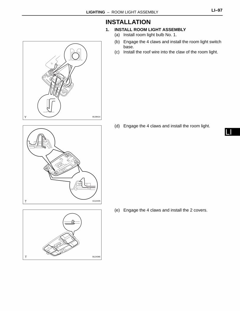
LIGHTING – ROOM LIGHT ASSEMBLY LI–97
I
LINSTALLATION1. INSTALL ROOM LIGHT ASSEMBLY
(a) Install room light bulb No. 1.(b) Engage the 4 claws and install the room light switch
base.(c) Install the roof wire into the claw of the room light.
(d) Engage the 4 claws and install the room light.
(e) Engage the 4 claws and install the 2 covers.
B138414
E114445
B124366
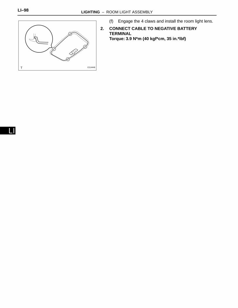
LI–98 LIGHTING – ROOM LIGHT ASSEMBLY
LI
(f) Engage the 4 claws and install the room light lens.
2. CONNECT CABLE TO NEGATIVE BATTERY TERMINALTorque: 3.9 N*m (40 kgf*cm, 35 in.*lbf)
E114446
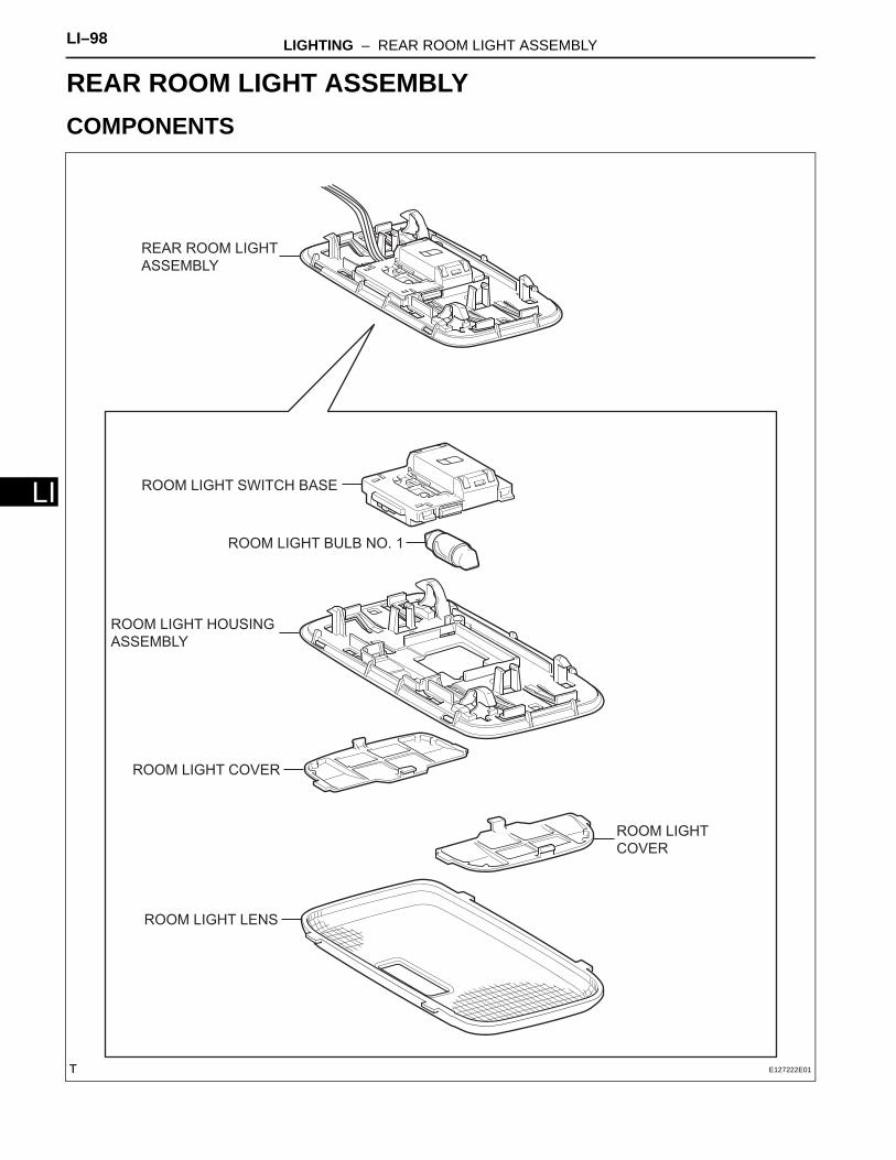
LI–98 LIGHTING – REAR ROOM LIGHT ASSEMBLY
LI
BODY ELECTRICALLIGHTINGREAR ROOM LIGHT ASSEMBLYCOMPONENTS
REAR ROOM LIGHT
ASSEMBLY
ROOM LIGHT SWITCH BASE
ROOM LIGHT BULB NO. 1
ROOM LIGHT HOUSING
ASSEMBLY
ROOM LIGHT COVER
ROOM LIGHT LENS
ROOM LIGHT
COVER
E127222E01
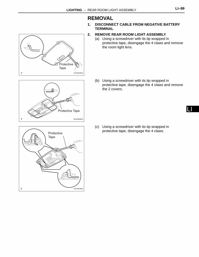
LIGHTING – REAR ROOM LIGHT ASSEMBLY LI–99
I
LREMOVAL1. DISCONNECT CABLE FROM NEGATIVE BATTERY
TERMINAL2. REMOVE REAR ROOM LIGHT ASSEMBLY
(a) Using a screwdriver with its tip wrapped in protective tape, disengage the 4 claws and remove the room light lens.
(b) Using a screwdriver with its tip wrapped in protective tape, disengage the 4 claws and remove the 2 covers.
(c) Using a screwdriver with its tip wrapped in protective tape, disengage the 4 claws.
Protective
Tape
E114441E01
Protective Tape
B124365E01
Protective
Tape
E114442E01
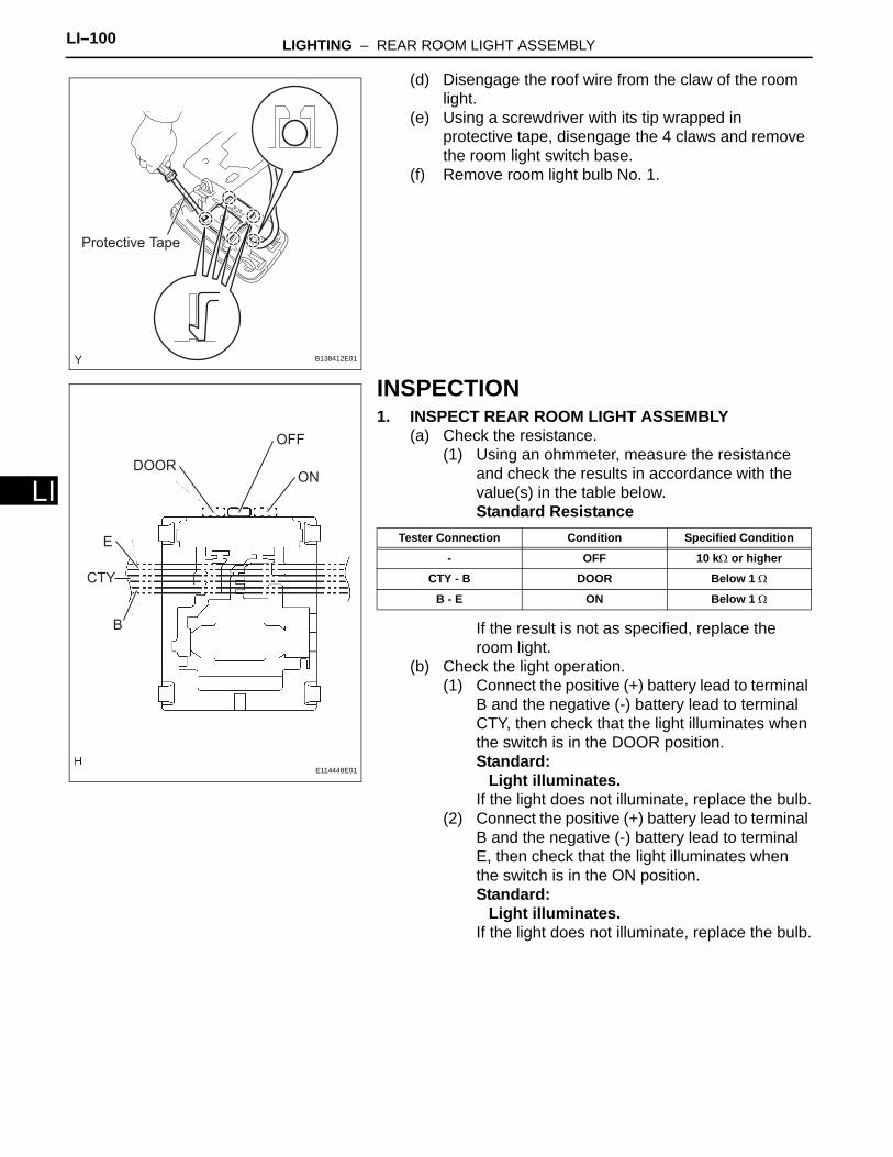
LI–100 LIGHTING – REAR ROOM LIGHT ASSEMBLY
LI
(d) Disengage the roof wire from the claw of the room light.
(e) Using a screwdriver with its tip wrapped in protective tape, disengage the 4 claws and remove the room light switch base.
(f) Remove room light bulb No. 1.
INSPECTION1. INSPECT REAR ROOM LIGHT ASSEMBLY
(a) Check the resistance.(1) Using an ohmmeter, measure the resistance
and check the results in accordance with the value(s) in the table below.Standard Resistance
If the result is not as specified, replace the room light.
(b) Check the light operation.(1) Connect the positive (+) battery lead to terminal
B and the negative (-) battery lead to terminal CTY, then check that the light illuminates when the switch is in the DOOR position.Standard:
Light illuminates.If the light does not illuminate, replace the bulb.
(2) Connect the positive (+) battery lead to terminal B and the negative (-) battery lead to terminal E, then check that the light illuminates when the switch is in the ON position.Standard:
Light illuminates.If the light does not illuminate, replace the bulb.
Protective Tape
B138412E01
DOOR
OFF
ON
E
CTY
B
E114448E01
Tester Connection Condition Specified Condition
- OFF 10 kΩ or higher
CTY - B DOOR Below 1 Ω
B - E ON Below 1 Ω
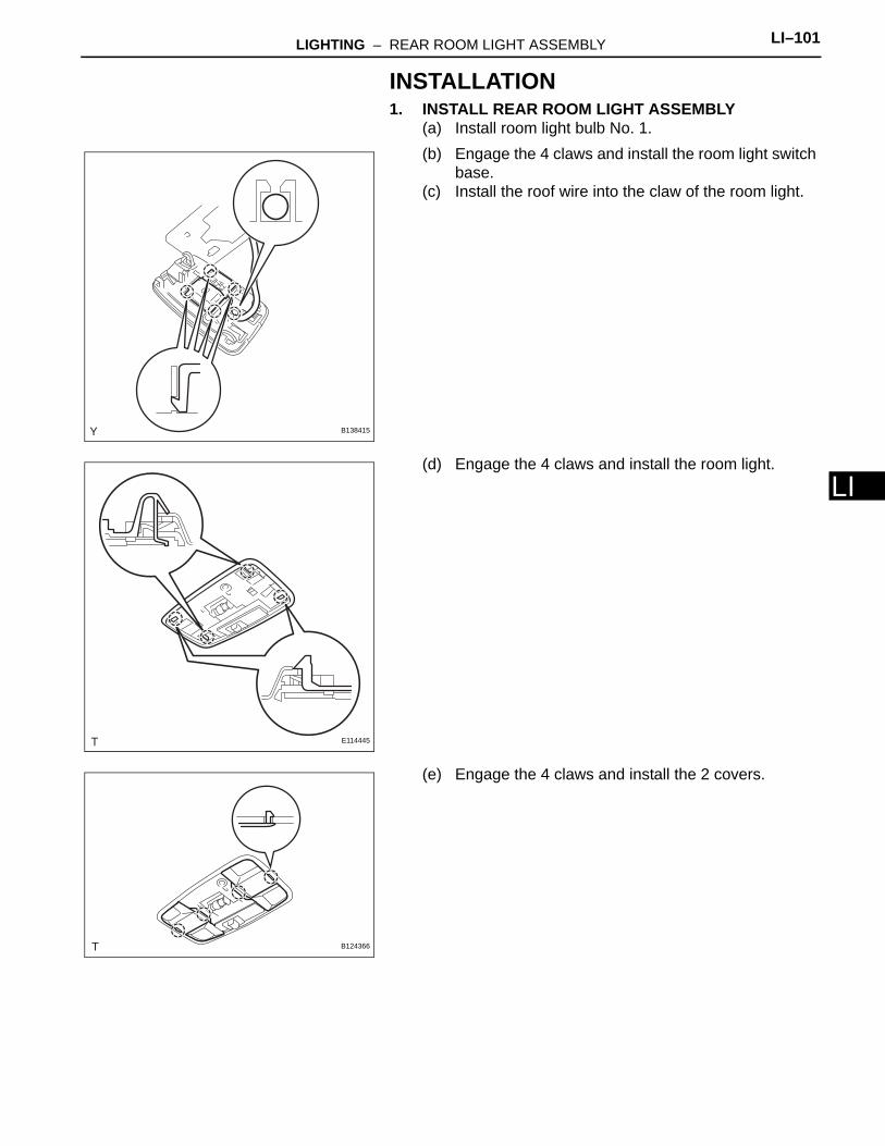
LIGHTING – REAR ROOM LIGHT ASSEMBLY LI–101
I
LINSTALLATION1. INSTALL REAR ROOM LIGHT ASSEMBLY
(a) Install room light bulb No. 1.(b) Engage the 4 claws and install the room light switch
base.(c) Install the roof wire into the claw of the room light.
(d) Engage the 4 claws and install the room light.
(e) Engage the 4 claws and install the 2 covers.
B138415
E114445
B124366

LI–102 LIGHTING – REAR ROOM LIGHT ASSEMBLY
LI
(f) Engage the 4 claws and install the room light lens.
2. CONNECT CABLE TO NEGATIVE BATTERY TERMINALTorque: 3.9 N*m (40 kgf*cm, 35 in.*lbf)
E114446
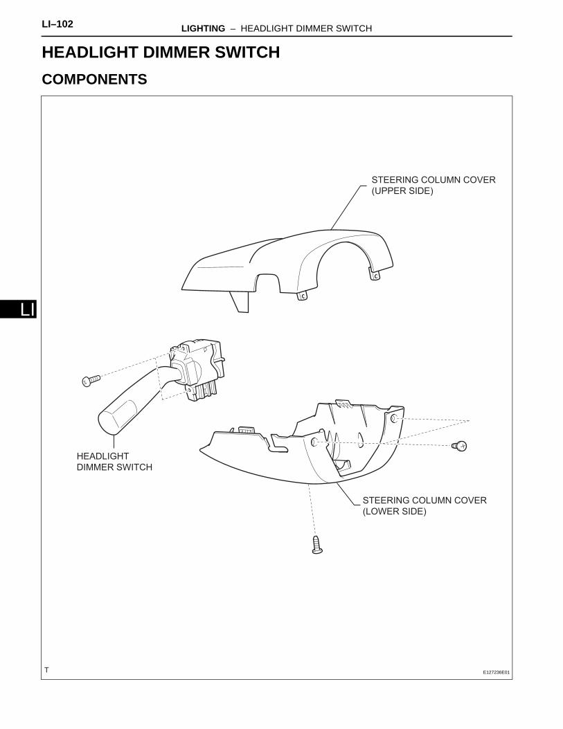
LI–102 LIGHTING – HEADLIGHT DIMMER SWITCH
LI
BODY ELECTRICALLIGHTINGHEADLIGHT DIMMER SWITCHCOMPONENTS
HEADLIGHT
DIMMER SWITCH
STEERING COLUMN COVER
(UPPER SIDE)
STEERING COLUMN COVER
(LOWER SIDE)
E127236E01
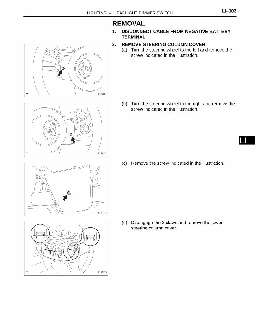
LIGHTING – HEADLIGHT DIMMER SWITCH LI–103
I
LREMOVAL1. DISCONNECT CABLE FROM NEGATIVE BATTERY
TERMINAL2. REMOVE STEERING COLUMN COVER
(a) Turn the steering wheel to the left and remove the screw indicated in the illustration.
(b) Turn the steering wheel to the right and remove the screw indicated in the illustration.
(c) Remove the screw indicated in the illustration.
(d) Disengage the 2 claws and remove the lower steering column cover.
E127231
E127232
E127233
E127235
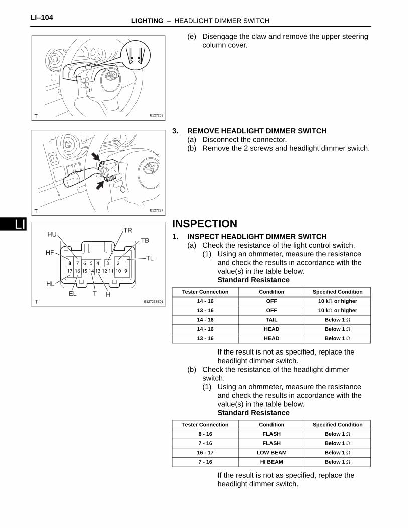
LI–104 LIGHTING – HEADLIGHT DIMMER SWITCH
LI
(e) Disengage the claw and remove the upper steering column cover.
3. REMOVE HEADLIGHT DIMMER SWITCH(a) Disconnect the connector.(b) Remove the 2 screws and headlight dimmer switch.
INSPECTION1. INSPECT HEADLIGHT DIMMER SWITCH
(a) Check the resistance of the light control switch.(1) Using an ohmmeter, measure the resistance
and check the results in accordance with the value(s) in the table below.Standard Resistance
If the result is not as specified, replace the headlight dimmer switch.
(b) Check the resistance of the headlight dimmer switch.(1) Using an ohmmeter, measure the resistance
and check the results in accordance with the value(s) in the table below.Standard Resistance
If the result is not as specified, replace the headlight dimmer switch.
E127253
E127237
88 6 37
17 16
2 1
10 915 14 13
5 4
12 11
HUTR
TB
TL
HTEL
HL
HF
E127238E01
Tester Connection Condition Specified Condition
14 - 16 OFF 10 kΩ or higher
13 - 16 OFF 10 kΩ or higher
14 - 16 TAIL Below 1 Ω
14 - 16 HEAD Below 1 Ω
13 - 16 HEAD Below 1 Ω
Tester Connection Condition Specified Condition
8 - 16 FLASH Below 1 Ω
7 - 16 FLASH Below 1 Ω
16 - 17 LOW BEAM Below 1 Ω
7 - 16 HI BEAM Below 1 Ω
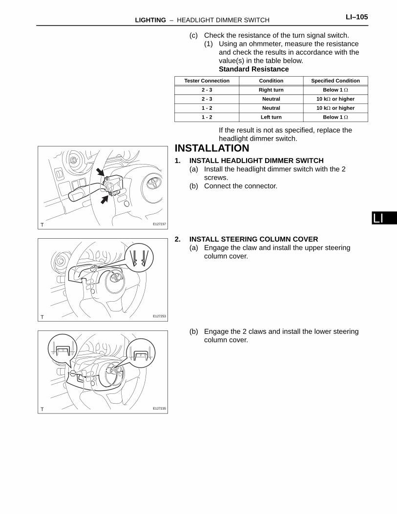
LIGHTING – HEADLIGHT DIMMER SWITCH LI–105
I
L(c) Check the resistance of the turn signal switch.(1) Using an ohmmeter, measure the resistance
and check the results in accordance with the value(s) in the table below.Standard Resistance
If the result is not as specified, replace the headlight dimmer switch.
INSTALLATION1. INSTALL HEADLIGHT DIMMER SWITCH
(a) Install the headlight dimmer switch with the 2 screws.
(b) Connect the connector.
2. INSTALL STEERING COLUMN COVER(a) Engage the claw and install the upper steering
column cover.
(b) Engage the 2 claws and install the lower steering column cover.
Tester Connection Condition Specified Condition
2 - 3 Right turn Below 1 Ω
2 - 3 Neutral 10 kΩ or higher
1 - 2 Neutral 10 kΩ or higher
1 - 2 Left turn Below 1 Ω
E127237
E127253
E127235
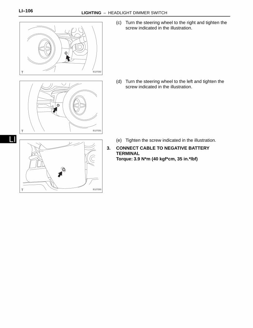
LI–106 LIGHTING – HEADLIGHT DIMMER SWITCH
LI
(c) Turn the steering wheel to the right and tighten the screw indicated in the illustration.
(d) Turn the steering wheel to the left and tighten the screw indicated in the illustration.
(e) Tighten the screw indicated in the illustration.
3. CONNECT CABLE TO NEGATIVE BATTERY TERMINALTorque: 3.9 N*m (40 kgf*cm, 35 in.*lbf)
E127232
E127231
E127233
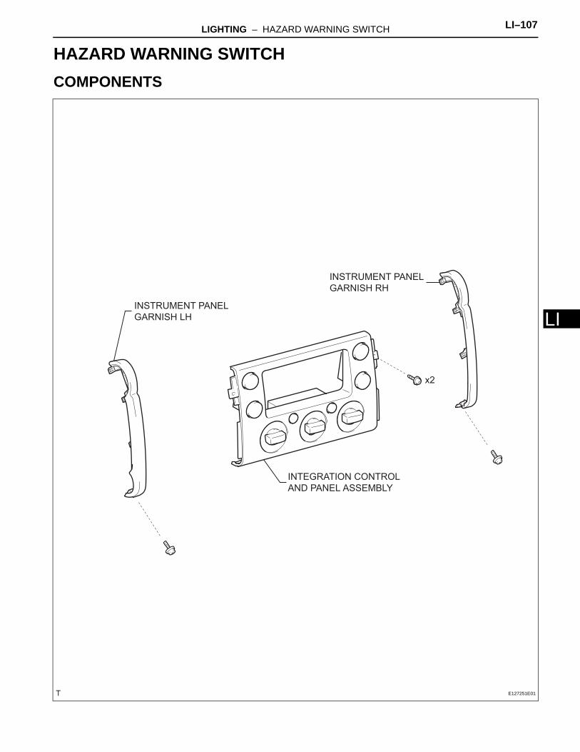
LIGHTING – HAZARD WARNING SWITCH LI–107
I
LBODY ELECTRICALLIGHTINGHAZARD WARNING SWITCHCOMPONENTS
INSTRUMENT PANEL
GARNISH LH
INSTRUMENT PANEL
GARNISH RH
INTEGRATION CONTROL
AND PANEL ASSEMBLY
x2
E127251E01
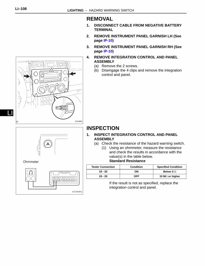
LI–108 LIGHTING – HAZARD WARNING SWITCH
LI
REMOVAL1. DISCONNECT CABLE FROM NEGATIVE BATTERY
TERMINAL2. REMOVE INSTRUMENT PANEL GARNISH LH (See
page IP-10)3. REMOVE INSTRUMENT PANEL GARNISH RH (See
page IP-10)4. REMOVE INTEGRATION CONTROL AND PANEL
ASSEMBLY(a) Remove the 2 screws.(b) Disengage the 4 clips and remove the integration
control and panel.
INSPECTION1. INSPECT INTEGRATION CONTROL AND PANEL
ASSEMBLY(a) Check the resistance of the hazard warning switch.
(1) Using an ohmmeter, measure the resistance and check the results in accordance with the value(s) in the table below.Standard Resistance
If the result is not as specified, replace the integration control and panel.
B133888
Ohmmeter
E127252E01
Tester Connection Condition Specified Condition
19 - 20 ON Below 3 Ω
19 - 20 OFF 10 MΩ or higher
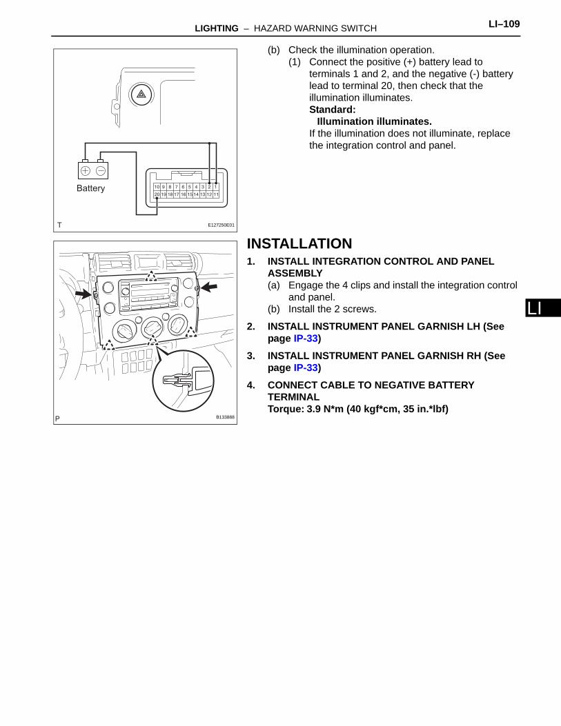
LIGHTING – HAZARD WARNING SWITCH LI–109
I
L(b) Check the illumination operation.(1) Connect the positive (+) battery lead to
terminals 1 and 2, and the negative (-) battery lead to terminal 20, then check that the illumination illuminates.Standard:
Illumination illuminates.If the illumination does not illuminate, replace the integration control and panel.
INSTALLATION1. INSTALL INTEGRATION CONTROL AND PANEL
ASSEMBLY(a) Engage the 4 clips and install the integration control
and panel.(b) Install the 2 screws.
2. INSTALL INSTRUMENT PANEL GARNISH LH (See page IP-33)
3. INSTALL INSTRUMENT PANEL GARNISH RH (See page IP-33)
4. CONNECT CABLE TO NEGATIVE BATTERY TERMINALTorque: 3.9 N*m (40 kgf*cm, 35 in.*lbf)
Battery
E127250E01
B133888
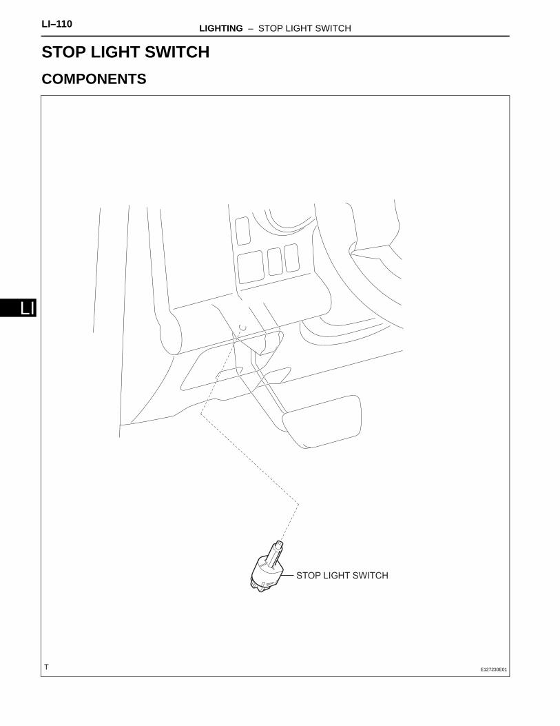
LI–110 LIGHTING – STOP LIGHT SWITCH
LI
BODY ELECTRICALLIGHTINGSTOP LIGHT SWITCHCOMPONENTS
STOP LIGHT SWITCH
E127230E01
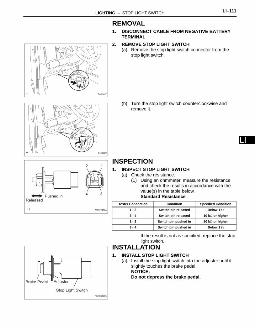
LIGHTING – STOP LIGHT SWITCH LI–111
I
LREMOVAL1. DISCONNECT CABLE FROM NEGATIVE BATTERY
TERMINAL2. REMOVE STOP LIGHT SWITCH
(a) Remove the stop light switch connector from the stop light switch.
(b) Turn the stop light switch counterclockwise and remove it.
INSPECTION1. INSPECT STOP LIGHT SWITCH
(a) Check the resistance.(1) Using an ohmmeter, measure the resistance
and check the results in accordance with the value(s) in the table below.Standard Resistance
If the result is not as specified, replace the stop light switch.
INSTALLATION1. INSTALL STOP LIGHT SWITCH
(a) Install the stop light switch into the adjuster until it slightly touches the brake pedal.NOTICE:Do not depress the brake pedal.
E127228
E127229
12
34Pushed in
Released
B113724E04
Tester Connection Condition Specified Condition
1 - 2 Switch pin released Below 1 Ω
3 - 4 Switch pin released 10 kΩ or higher
1 - 2 Switch pin pushed in 10 kΩ or higher
3 - 4 Switch pin pushed in Below 1 Ω
AdjusterBrake Pedal
Stop Light Switch
F049043E05
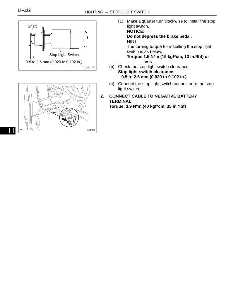
LI–112 LIGHTING – STOP LIGHT SWITCH
LI
(1) Make a quarter turn clockwise to install the stop light switch.NOTICE:Do not depress the brake pedal.HINT:The turning torque for installing the stop light switch is as below.Torque: 1.5 N*m (15 kgf*cm, 13 in.*lbf) or
less(b) Check the stop light switch clearance.
Stop light switch clearance:0.5 to 2.6 mm (0.020 to 0.102 in.)
(c) Connect the stop light switch connector to the stop light switch.
2. CONNECT CABLE TO NEGATIVE BATTERY TERMINALTorque: 3.9 N*m (40 kgf*cm, 35 in.*lbf)
Shaft
Stop Light Switch
0.5 to 2.6 mm (0.020 to 0.102 in.)
C133112E01
E127228
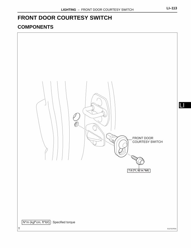
LIGHTING – FRONT DOOR COURTESY SWITCH LI–113
I
LBODY ELECTRICALLIGHTINGFRONT DOOR COURTESY SWITCHCOMPONENTS
FRONT DOOR
COURTESY SWITCH
N*m (kgf*cm, ft*lbf) : Specified torque
7.0 (71, 62 in.*lbf)
E127227E01
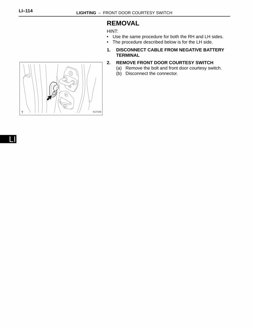
LI–114 LIGHTING – FRONT DOOR COURTESY SWITCH
LI
REMOVALHINT:• Use the same procedure for both the RH and LH sides.• The procedure described below is for the LH side.
1. DISCONNECT CABLE FROM NEGATIVE BATTERY TERMINAL
2. REMOVE FRONT DOOR COURTESY SWITCH(a) Remove the bolt and front door courtesy switch.(b) Disconnect the connector.
E127226
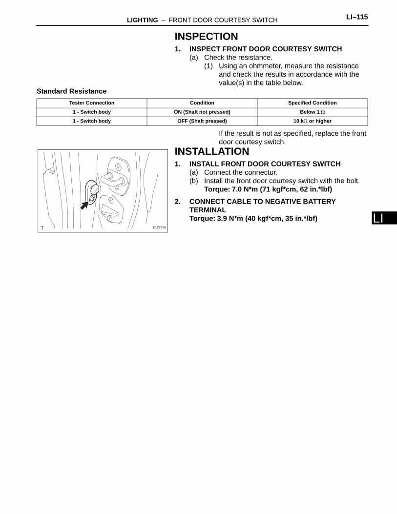
LIGHTING – FRONT DOOR COURTESY SWITCH LI–115
I
LINSPECTION1. INSPECT FRONT DOOR COURTESY SWITCH
(a) Check the resistance.(1) Using an ohmmeter, measure the resistance
and check the results in accordance with the value(s) in the table below.
Standard Resistance
If the result is not as specified, replace the front door courtesy switch.
INSTALLATION1. INSTALL FRONT DOOR COURTESY SWITCH
(a) Connect the connector.(b) Install the front door courtesy switch with the bolt.
Torque: 7.0 N*m (71 kgf*cm, 62 in.*lbf)2. CONNECT CABLE TO NEGATIVE BATTERY
TERMINALTorque: 3.9 N*m (40 kgf*cm, 35 in.*lbf)
Tester Connection Condition Specified Condition
1 - Switch body ON (Shaft not pressed) Below 1 Ω
1 - Switch body OFF (Shaft pressed) 10 kΩ or higher
E127226
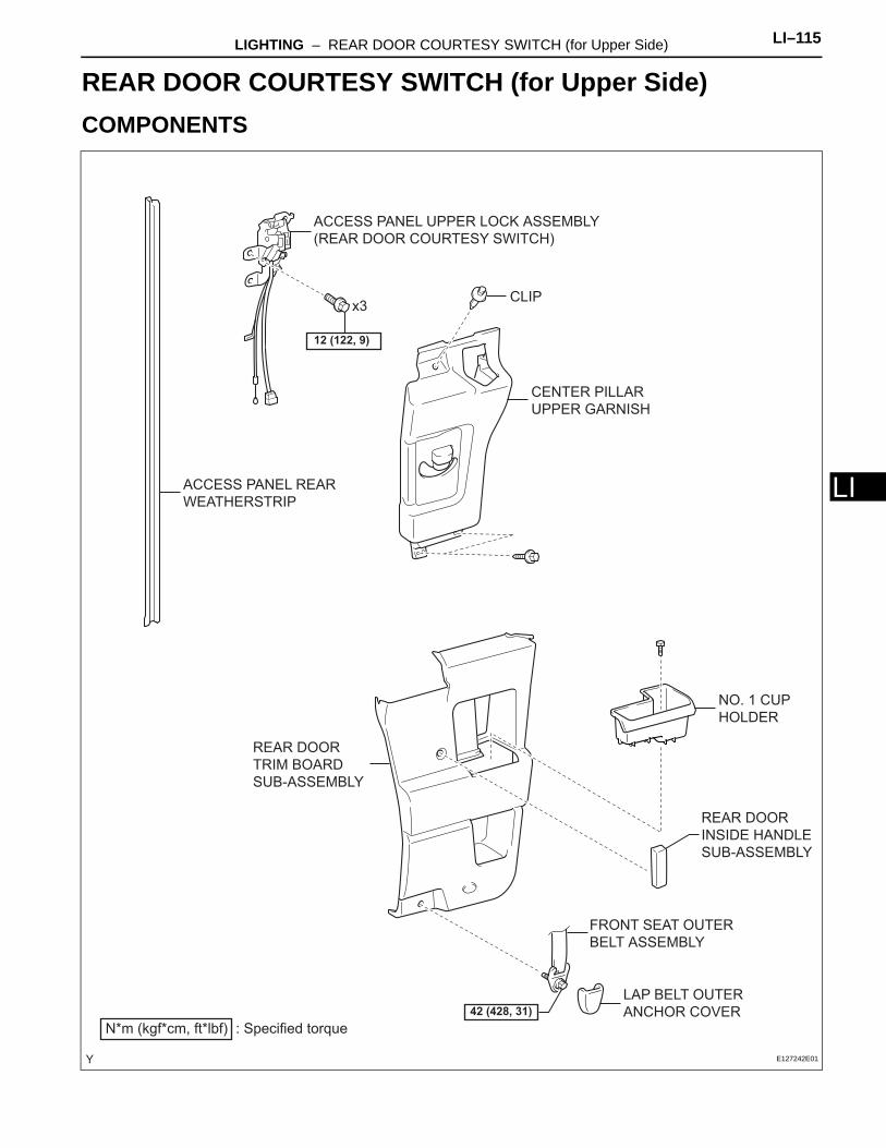
LIGHTING – REAR DOOR COURTESY SWITCH (for Upper Side) LI–115
I
LBODY ELECTRICALLIGHTINGREAR DOOR COURTESY SWITCH (for Upper Side)COMPONENTS
ACCESS PANEL REAR
WEATHERSTRIP
ACCESS PANEL UPPER LOCK ASSEMBLY
(REAR DOOR COURTESY SWITCH)
CENTER PILLAR
UPPER GARNISH
LAP BELT OUTER
ANCHOR COVER
NO. 1 CUP
HOLDER
REAR DOOR
INSIDE HANDLE
SUB-ASSEMBLY
REAR DOOR
TRIM BOARD
SUB-ASSEMBLY
CLIP
FRONT SEAT OUTER
BELT ASSEMBLY
N*m (kgf*cm, ft*lbf) : Specified torque
42 (428, 31)
12 (122, 9)
x3
E127242E01
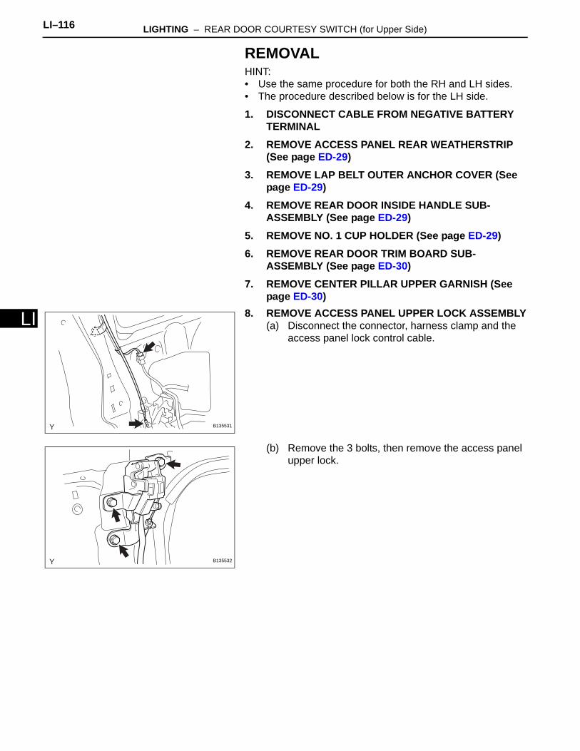
LI–116 LIGHTING – REAR DOOR COURTESY SWITCH (for Upper Side)
LI
REMOVALHINT:• Use the same procedure for both the RH and LH sides.• The procedure described below is for the LH side.
1. DISCONNECT CABLE FROM NEGATIVE BATTERY TERMINAL
2. REMOVE ACCESS PANEL REAR WEATHERSTRIP (See page ED-29)
3. REMOVE LAP BELT OUTER ANCHOR COVER (See page ED-29)
4. REMOVE REAR DOOR INSIDE HANDLE SUB-ASSEMBLY (See page ED-29)
5. REMOVE NO. 1 CUP HOLDER (See page ED-29)6. REMOVE REAR DOOR TRIM BOARD SUB-
ASSEMBLY (See page ED-30)7. REMOVE CENTER PILLAR UPPER GARNISH (See
page ED-30)8. REMOVE ACCESS PANEL UPPER LOCK ASSEMBLY
(a) Disconnect the connector, harness clamp and the access panel lock control cable.
(b) Remove the 3 bolts, then remove the access panel upper lock.
B135531
B135532
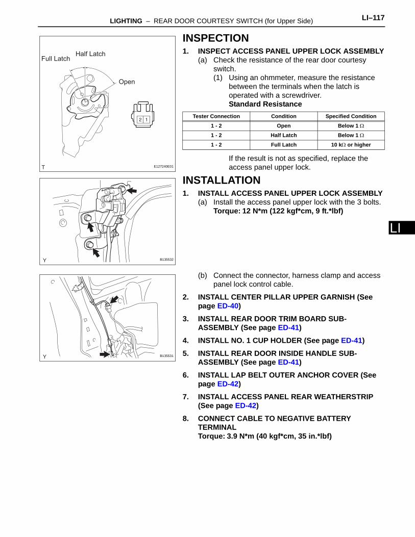
LIGHTING – REAR DOOR COURTESY SWITCH (for Upper Side) LI–117
I
LINSPECTION1. INSPECT ACCESS PANEL UPPER LOCK ASSEMBLY
(a) Check the resistance of the rear door courtesy switch.(1) Using an ohmmeter, measure the resistance
between the terminals when the latch is operated with a screwdriver.Standard Resistance
If the result is not as specified, replace the access panel upper lock.
INSTALLATION1. INSTALL ACCESS PANEL UPPER LOCK ASSEMBLY
(a) Install the access panel upper lock with the 3 bolts.Torque: 12 N*m (122 kgf*cm, 9 ft.*lbf)
(b) Connect the connector, harness clamp and access panel lock control cable.
2. INSTALL CENTER PILLAR UPPER GARNISH (See page ED-40)
3. INSTALL REAR DOOR TRIM BOARD SUB-ASSEMBLY (See page ED-41)
4. INSTALL NO. 1 CUP HOLDER (See page ED-41)5. INSTALL REAR DOOR INSIDE HANDLE SUB-
ASSEMBLY (See page ED-41)6. INSTALL LAP BELT OUTER ANCHOR COVER (See
page ED-42)7. INSTALL ACCESS PANEL REAR WEATHERSTRIP
(See page ED-42)8. CONNECT CABLE TO NEGATIVE BATTERY
TERMINALTorque: 3.9 N*m (40 kgf*cm, 35 in.*lbf)
Open
Full LatchHalf Latch
E127240E01
Tester Connection Condition Specified Condition
1 - 2 Open Below 1 Ω
1 - 2 Half Latch Below 1 Ω
1 - 2 Full Latch 10 kΩ or higher
B135532
B135531
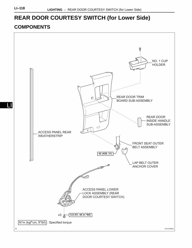
LI–118 LIGHTING – REAR DOOR COURTESY SWITCH (for Lower Side)
LI
BODY ELECTRICALLIGHTINGREAR DOOR COURTESY SWITCH (for Lower Side)COMPONENTS
ACCESS PANEL LOWER
LOCK ASSEMBLY (REAR
DOOR COURTESY SWITCH)
ACCESS PANEL REAR
WEATHERSTRIP
LAP BELT OUTER
ANCHOR COVER
NO. 1 CUP
HOLDER
REAR DOOR TRIM
BOARD SUB-ASSEMBLY
N*m (kgf*cm, ft*lbf) : Specified torque
42 (428, 31)
5.0 (51, 44 in.*lbf)
FRONT SEAT OUTER
BELT ASSEMBLY
x3
REAR DOOR
INSIDE HANDLE
SUB-ASSEMBLY
E127243E01

LIGHTING – REAR DOOR COURTESY SWITCH (for Lower Side) LI–119
I
LREMOVALHINT:• Use the same procedure for both the RH and LH sides.• The procedure described below is for the RH side.
1. DISCONNECT CABLE FROM NEGATIVE BATTERY TERMINAL
2. REMOVE ACCESS PANEL REAR WEATHERSTRIP (See page ED-29)
3. REMOVE LAP BELT OUTER ANCHOR COVER (See page ED-29)
4. REMOVE REAR DOOR INSIDE HANDLE SUB-ASSEMBLY (See page ED-29)
5. REMOVE NO. 1 CUP HOLDER (See page ED-29)6. REMOVE REAR DOOR TRIM BOARD SUB-
ASSEMBLY (See page ED-30)7. REMOVE ACCESS PANEL LOWER LOCK
ASSEMBLY(a) Disconnect the connector, connector clamp and
access panel lock control cable.
(b) Using "Torx" socket wrench T30, remove the 3 screws.
(c) Remove the access panel lower lock by sliding it upward.
B135561
B135562

LI–120 LIGHTING – REAR DOOR COURTESY SWITCH (for Lower Side)
LI
INSPECTION1. INSPECT ACCESS PANEL LOWER LOCK
ASSEMBLY(a) Check the resistance of the rear door courtesy
switch.(1) Using an ohmmeter, measure the resistance
between the terminals when the latch is operated with a screwdriver.Standard Resistance
If the result is not as specified, replace the access panel lower lock.
INSTALLATION1. INSTALL ACCESS PANEL LOWER LOCK ASSEMBLY
(a) Install the access panel lower lock onto the rear door.Torque: 5.0 N*m (51 kgf*cm, 44 in.*lbf)
(b) Connect the connector, connector clamp and access panel lock control cable.
2. INSTALL REAR DOOR TRIM BOARD SUB-ASSEMBLY (See page ED-41)
3. INSTALL NO. 1 CUP HOLDER (See page ED-41)4. INSTALL REAR DOOR INSIDE HANDLE SUB-
ASSEMBLY (See page ED-41)5. INSTALL LAP BELT OUTER ANCHOR COVER (See
page ED-42)6. INSTALL ACCESS PANEL REAR WEATHERSTRIP
(See page ED-42)7. CONNECT CABLE TO NEGATIVE BATTERY
TERMINALTorque: 3.9 N*m (40 kgf*cm, 35 in.*lbf)
Open
Half LatchFull
Latch
E127241E01
Tester Connection Condition Specified Condition
1 - 2 Open Below 1 Ω
1 - 2 Half Latch Below 1 Ω
1 - 2 Full Latch 10 kΩ or higher
B135562
B135561

LIGHTING – BACK DOOR COURTESY SWITCH LI–121
I
LBODY ELECTRICALLIGHTINGBACK DOOR COURTESY SWITCHCOMPONENTS
BACK DOOR COURTESY
SWITCH
N*m (kgf*cm, ft*lbf) : Specified torque
7.0 (71, 62 in.*lbf)
E127225E01
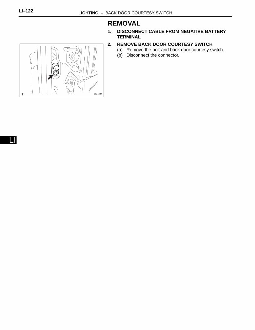
LI–122 LIGHTING – BACK DOOR COURTESY SWITCH
LI
REMOVAL1. DISCONNECT CABLE FROM NEGATIVE BATTERY
TERMINAL2. REMOVE BACK DOOR COURTESY SWITCH
(a) Remove the bolt and back door courtesy switch.(b) Disconnect the connector.
E127224

LIGHTING – BACK DOOR COURTESY SWITCH LI–123
I
LINSPECTION1. INSPECT BACK DOOR COURTESY SWITCH
(a) Check the resistance.(1) Using an ohmmeter, measure the resistance
and check the results in accordance with the value(s) in the table below.
Standard Resistance
If the result is not as specified, replace the back door courtesy switch.
INSTALLATION1. INSTALL BACK DOOR COURTESY SWITCH
(a) Connect the connector.(b) Install the back door courtesy switch with the bolt.
Torque: 7.0 N*m (71 kgf*cm, 62 in.*lbf)2. CONNECT CABLE TO NEGATIVE BATTERY
TERMINALTorque: 3.9 N*m (40 kgf*cm, 35 in.*lbf)
Tester Connection Condition Specified Condition
1 - Switch body ON (Shaft not pressed) Below 1 Ω
1 - Switch body OFF (Shaft not pressed) 10 kΩ or higher
E127224
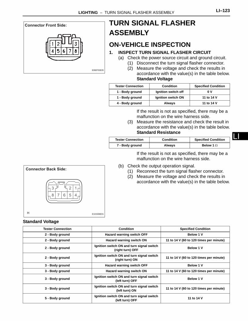
LIGHTING – TURN SIGNAL FLASHER ASSEMBLY LI–123
I
LTURN SIGNAL FLASHER ASSEMBLYON-VEHICLE INSPECTION1. INSPECT TURN SIGNAL FLASHER CIRCUIT
(a) Check the power source circuit and ground circuit.(1) Disconnect the turn signal flasher connector.(2) Measure the voltage and check the results in
accordance with the value(s) in the table below.Standard Voltage
If the result is not as specified, there may be a malfunction on the wire harness side.
(3) Measure the resistance and check the result in accordance with the value(s) in the table below.Standard Resistance
If the result is not as specified, there may be a malfunction on the wire harness side.
(b) Check the output operation signal.(1) Reconnect the turn signal flasher connector.(2) Measure the voltage and check the results in
accordance with the value(s) in the table below.
Standard Voltage
Connector Front Side:
E068703E05
Tester Connection Condition Specified Condition
1 - Body ground Ignition switch off 0 V
1 - Body ground Ignition switch ON 11 to 14 V
4 - Body ground Always 11 to 14 V
Tester Connection Condition Specified Condition
7 - Body ground Always Below 1 Ω
Connector Back Side:
E101506E01
Tester Connection Condition Specified Condition
2 - Body ground Hazard warning switch OFF Below 1 V
2 - Body ground Hazard warning switch ON 11 to 14 V (60 to 120 times per minute)
2 - Body ground Ignition switch ON and turn signal switch (right turn) OFF Below 1 V
2 - Body ground Ignition switch ON and turn signal switch (right turn) ON 11 to 14 V (60 to 120 times per minute)
3 - Body ground Hazard warning switch OFF Below 1 V
3 - Body ground Hazard warning switch ON 11 to 14 V (60 to 120 times per minute)
3 - Body ground Ignition switch ON and turn signal switch (left turn) OFF Below 1 V
3 - Body ground Ignition switch ON and turn signal switch (left turn) ON 11 to 14 V (60 to 120 times per minute)
5 - Body ground Ignition switch ON and turn signal switch (left turn) OFF 11 to 14 V
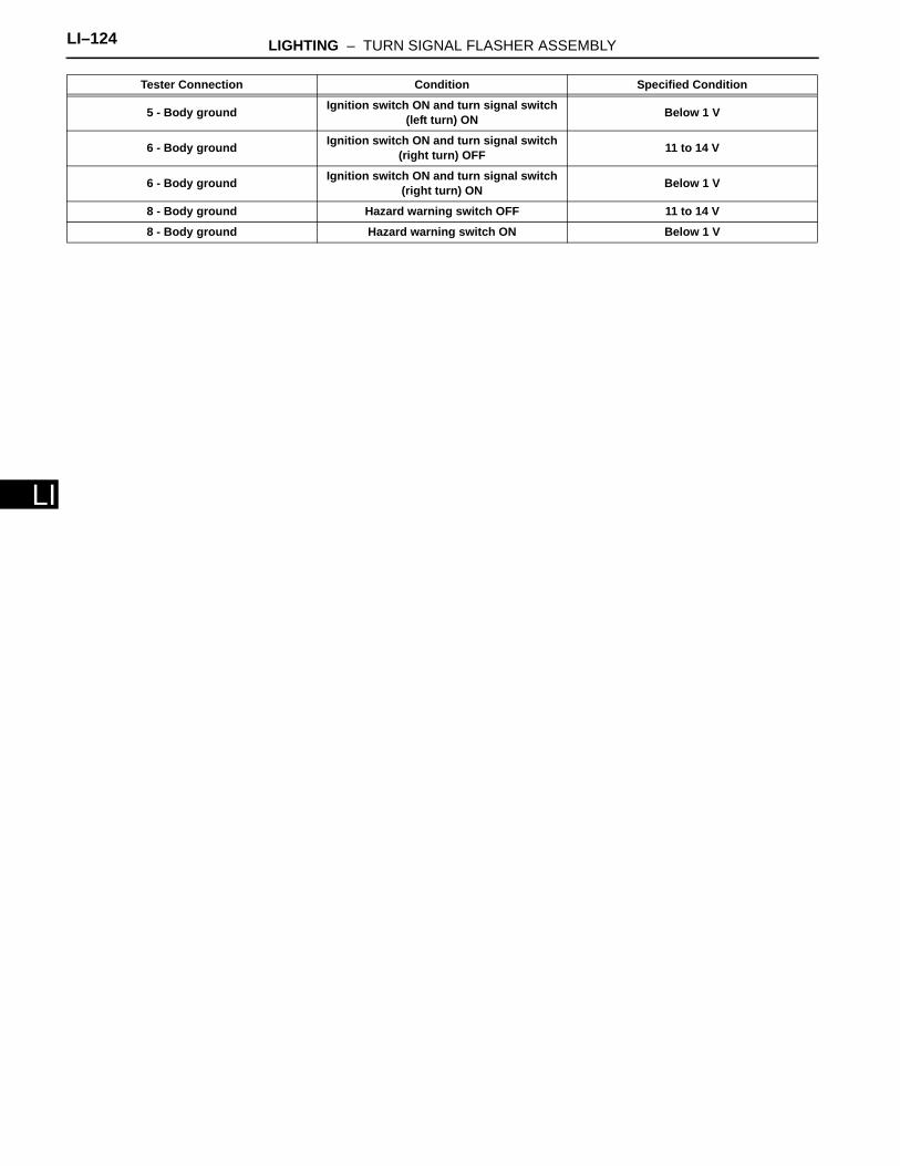
LI–124 LIGHTING – TURN SIGNAL FLASHER ASSEMBLY
LI
5 - Body ground Ignition switch ON and turn signal switch (left turn) ON Below 1 V
6 - Body ground Ignition switch ON and turn signal switch (right turn) OFF 11 to 14 V
6 - Body ground Ignition switch ON and turn signal switch (right turn) ON Below 1 V
8 - Body ground Hazard warning switch OFF 11 to 14 V
8 - Body ground Hazard warning switch ON Below 1 V
Tester Connection Condition Specified Condition
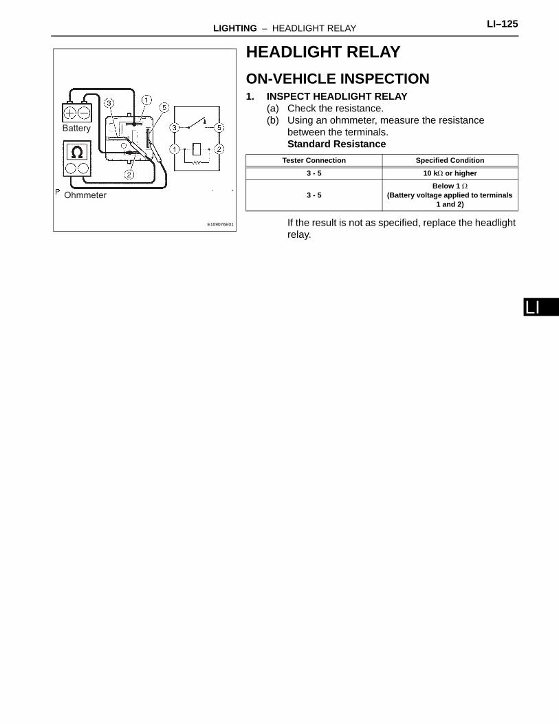
LIGHTING – HEADLIGHT RELAY LI–125
LI
HEADLIGHT RELAYON-VEHICLE INSPECTION1. INSPECT HEADLIGHT RELAY
(a) Check the resistance.(b) Using an ohmmeter, measure the resistance
between the terminals.Standard Resistance
If the result is not as specified, replace the headlight relay.
Battery
Ohmmeter
E109076E01
Tester Connection Specified Condition
3 - 5 10 kΩ or higher
3 - 5Below 1 Ω
(Battery voltage applied to terminals 1 and 2)
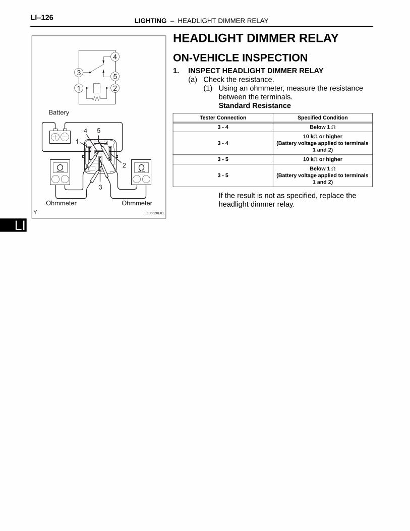
LI–126 LIGHTING – HEADLIGHT DIMMER RELAY
LI
HEADLIGHT DIMMER RELAYON-VEHICLE INSPECTION1. INSPECT HEADLIGHT DIMMER RELAY
(a) Check the resistance.(1) Using an ohmmeter, measure the resistance
between the terminals.Standard Resistance
If the result is not as specified, replace the headlight dimmer relay.Ohmmeter
Battery
Ohmmeter
1
2
3
4 5
E106620E01
Tester Connection Specified Condition
3 - 4 Below 1 Ω
3 - 410 kΩ or higher
(Battery voltage applied to terminals 1 and 2)
3 - 5 10 kΩ or higher
3 - 5Below 1 Ω
(Battery voltage applied to terminals 1 and 2)
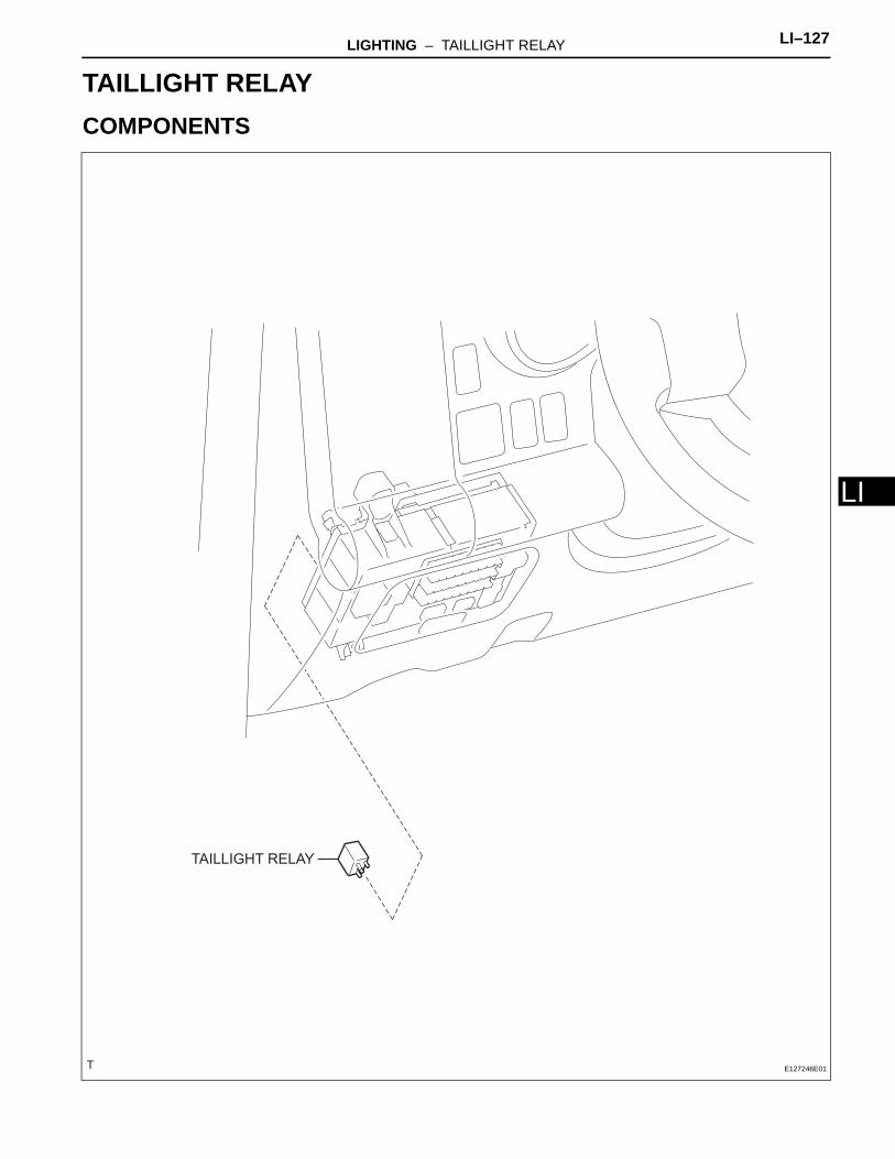
LIGHTING – TAILLIGHT RELAY LI–127
I
LBODY ELECTRICALLIGHTINGTAILLIGHT RELAYCOMPONENTS
TAILLIGHT RELAY
E127246E01
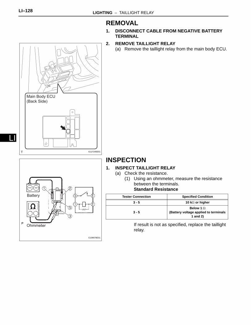
LI–128 LIGHTING – TAILLIGHT RELAY
LI
REMOVAL1. DISCONNECT CABLE FROM NEGATIVE BATTERY
TERMINAL2. REMOVE TAILLIGHT RELAY
(a) Remove the taillight relay from the main body ECU.
INSPECTION1. INSPECT TAILLIGHT RELAY
(a) Check the resistance.(1) Using an ohmmeter, measure the resistance
between the terminals.Standard Resistance
If result is not as specified, replace the taillight relay.
Main Body ECU
(Back Side)
E127245E01
Battery
Ohmmeter
E109078E01
Tester Connection Specified Condition
3 - 5 10 kΩ or higher
3 - 5Below 1 Ω
(Battery voltage applied to terminals 1 and 2)
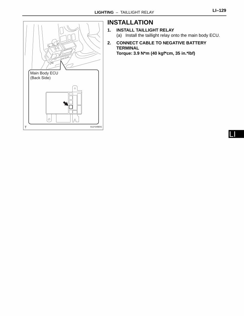
LIGHTING – TAILLIGHT RELAY LI–129
I
LINSTALLATION1. INSTALL TAILLIGHT RELAY
(a) Install the taillight relay onto the main body ECU.
2. CONNECT CABLE TO NEGATIVE BATTERY TERMINALTorque: 3.9 N*m (40 kgf*cm, 35 in.*lbf)
Main Body ECU
(Back Side)
E127245E01