Light
172
LIGHT Reflection of Light Refraction of Light Thin Converging and Diverging Lens Light 1
-
Upload
shafiesofian -
Category
Education
-
view
518 -
download
0
Transcript of Light
LIGHTReflection of Light
Refraction of Light
Thin Converging and Diverging Lens
Light 1
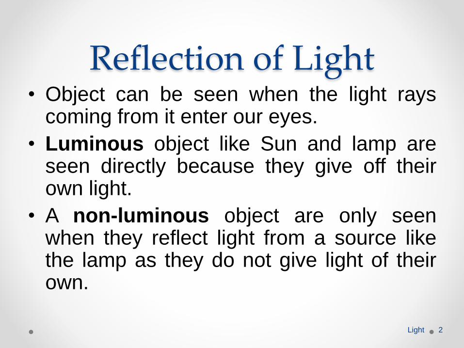
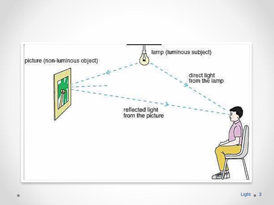
Reflection of Light• Object can be seen when the light rays
coming from it enter our eyes.
• Luminous object like Sun and lamp areseen directly because they give off theirown light.
• A non-luminous object are only seenwhen they reflect light from a source likethe lamp as they do not give light of theirown.
Light 2
Light 3
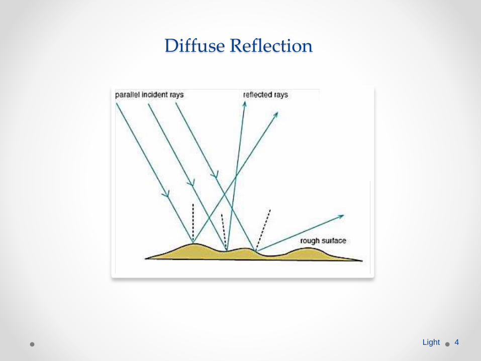
Diffuse Reflection
Light 4
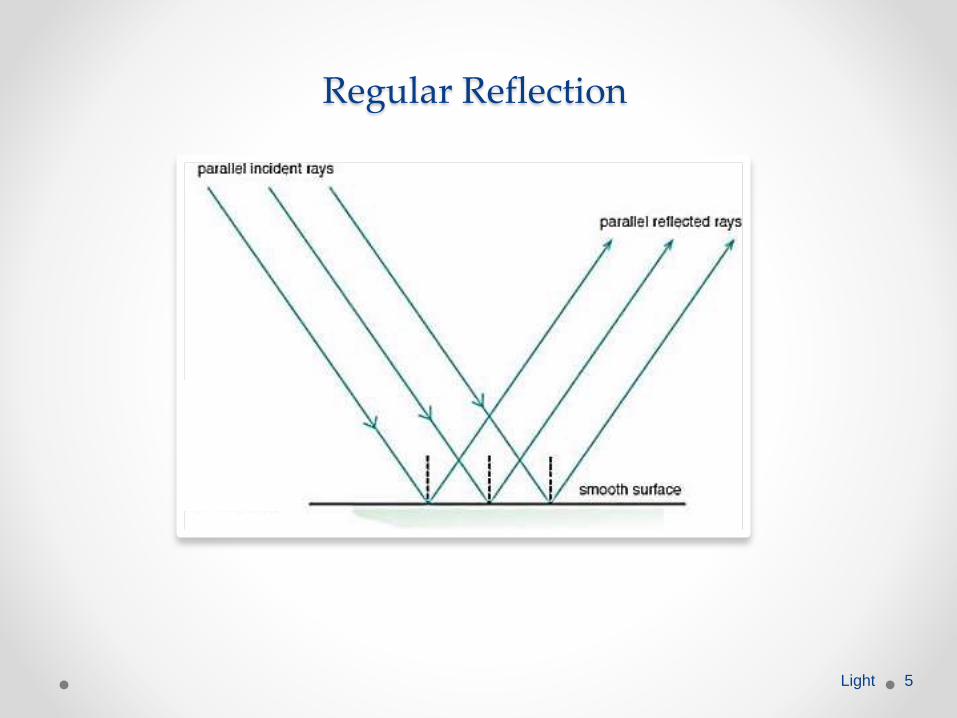
Regular Reflection
Light 5
Reflection of lightDefine the terms used in reflection including normal, angle of incidence and angle of reflection.
Light 6
Reflection of Light
Light 7
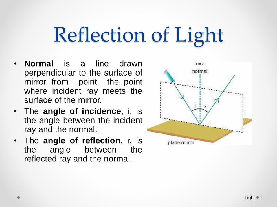
• Normal is a line drawnperpendicular to the surface ofmirror from point the pointwhere incident ray meets thesurface of the mirror.
• The angle of incidence, i, isthe angle between the incidentray and the normal.
• The angle of reflection, r, isthe angle between thereflected ray and the normal.
Reflection of LightDescribe an experiment to illustrate the law of
reflection.
Light 8
• Aim: To study law of reflection.
• Apparatus:o Plane Mirror
o Ray box
o Protractor
Light 9
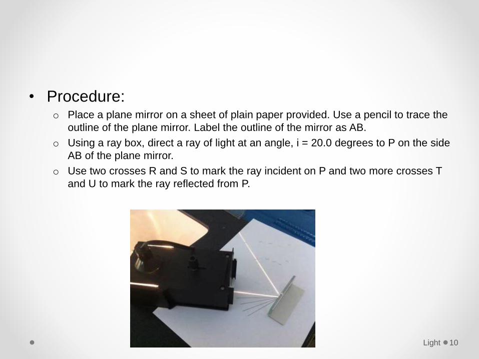
• Procedure:o Place a plane mirror on a sheet of plain paper provided. Use a pencil to trace the
outline of the plane mirror. Label the outline of the mirror as AB.
o Using a ray box, direct a ray of light at an angle, i = 20.0 degrees to P on the side
AB of the plane mirror.
o Use two crosses R and S to mark the ray incident on P and two more crosses T
and U to mark the ray reflected from P.
Light 10
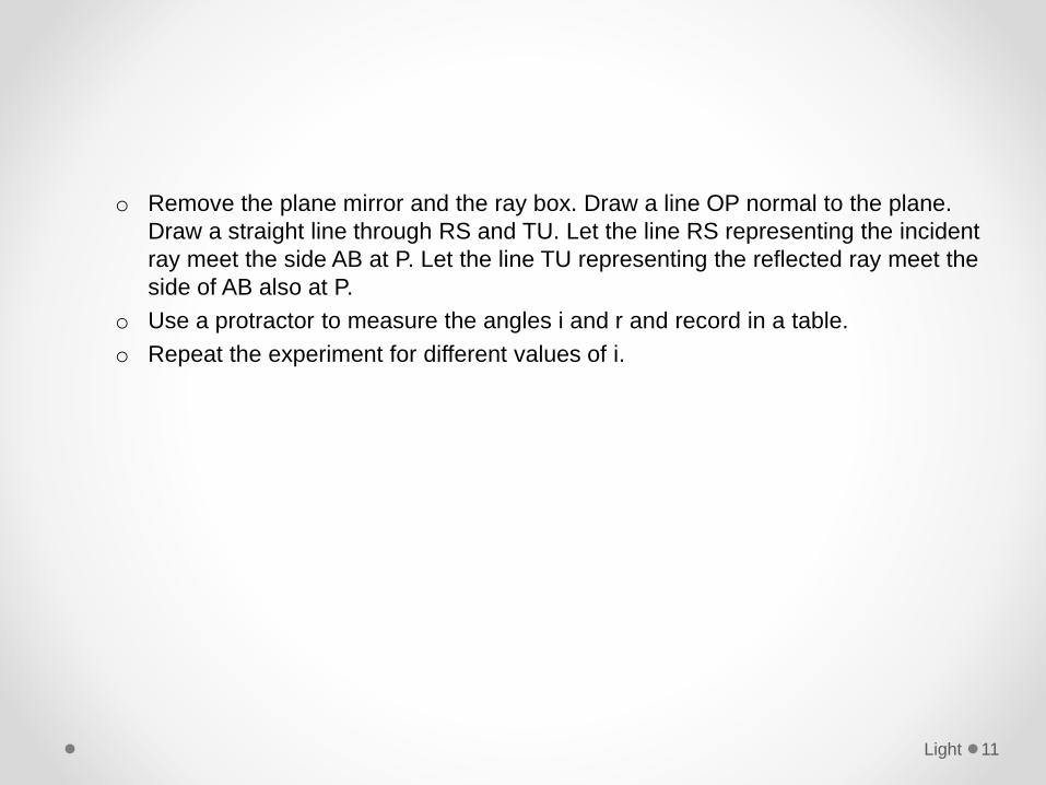
o Remove the plane mirror and the ray box. Draw a line OP normal to the plane.
Draw a straight line through RS and TU. Let the line RS representing the incident
ray meet the side AB at P. Let the line TU representing the reflected ray meet the
side of AB also at P.
o Use a protractor to measure the angles i and r and record in a table.
o Repeat the experiment for different values of i.
Light 11
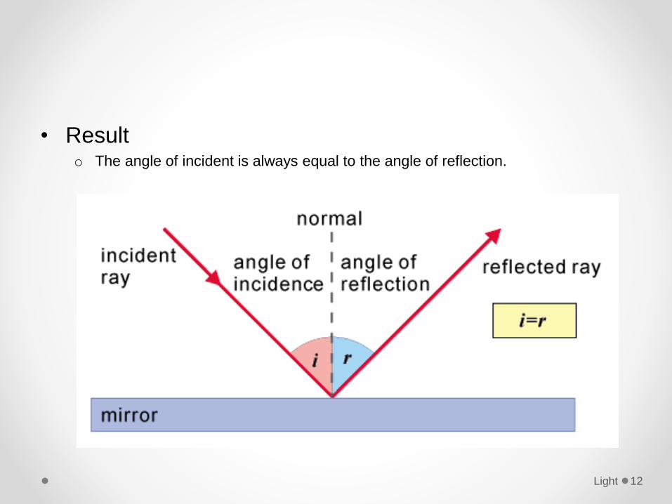
• Resulto The angle of incident is always equal to the angle of reflection.
Light 12
Reflection of LightDescribe an experiment to find the position and characteristics of an optical image formed by a plane mirror.
Light 13
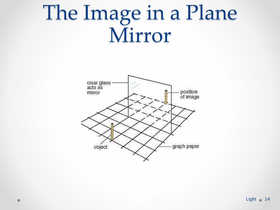
The Image in a Plane Mirror
Light 14
• Aim: To determine the position of image on a plane
mirror.
• Apparatus:o Standing object (optical pin)
o Mirror
o Graph paper
Light 15
• Procedure:o Place the mirror on the graph paper
o Place object in front of the mirror
o Observe the image on the mirror by counting the number of square on the graph
paper
• Resulto Distance of object and mirror is equal distance of image and the mirror
Light 16
Image formed by Plane Mirror
• The image is virtual.
• The image is upright.
• The image formed has the same size as the object.
• The image is as far behind the mirror as the object is in
front of the mirror.
• The object and the image is perpendicular to the mirror.
• The image is laterally inverted. (left-to-right inversion)
Light 17
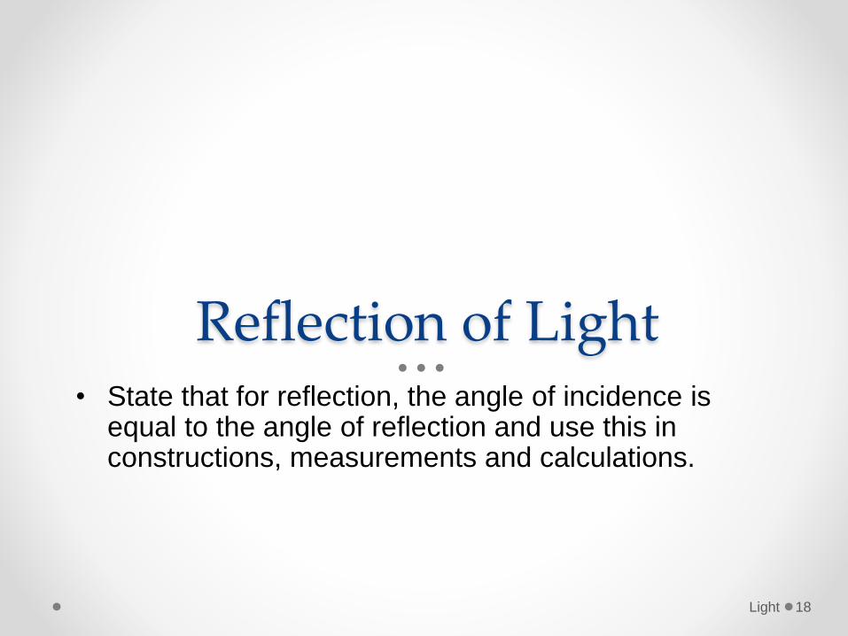
Reflection of Light• State that for reflection, the angle of incidence is
equal to the angle of reflection and use this in constructions, measurements and calculations.
Light 18
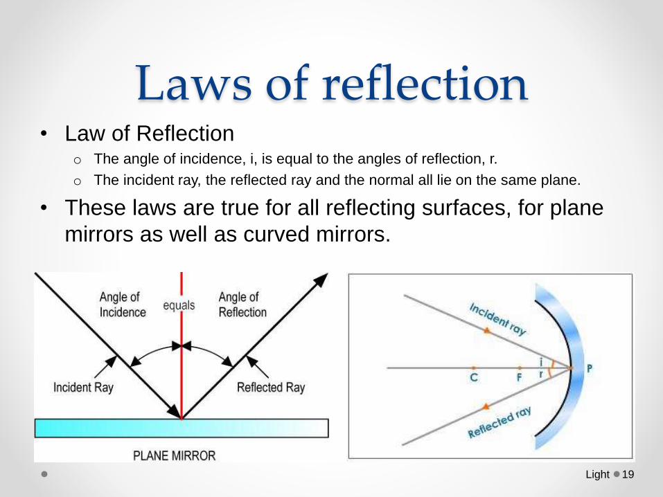
Laws of reflection• Law of Reflection
o The angle of incidence, i, is equal to the angles of reflection, r.
o The incident ray, the reflected ray and the normal all lie on the same plane.
• These laws are true for all reflecting surfaces, for plane
mirrors as well as curved mirrors.
Light 19
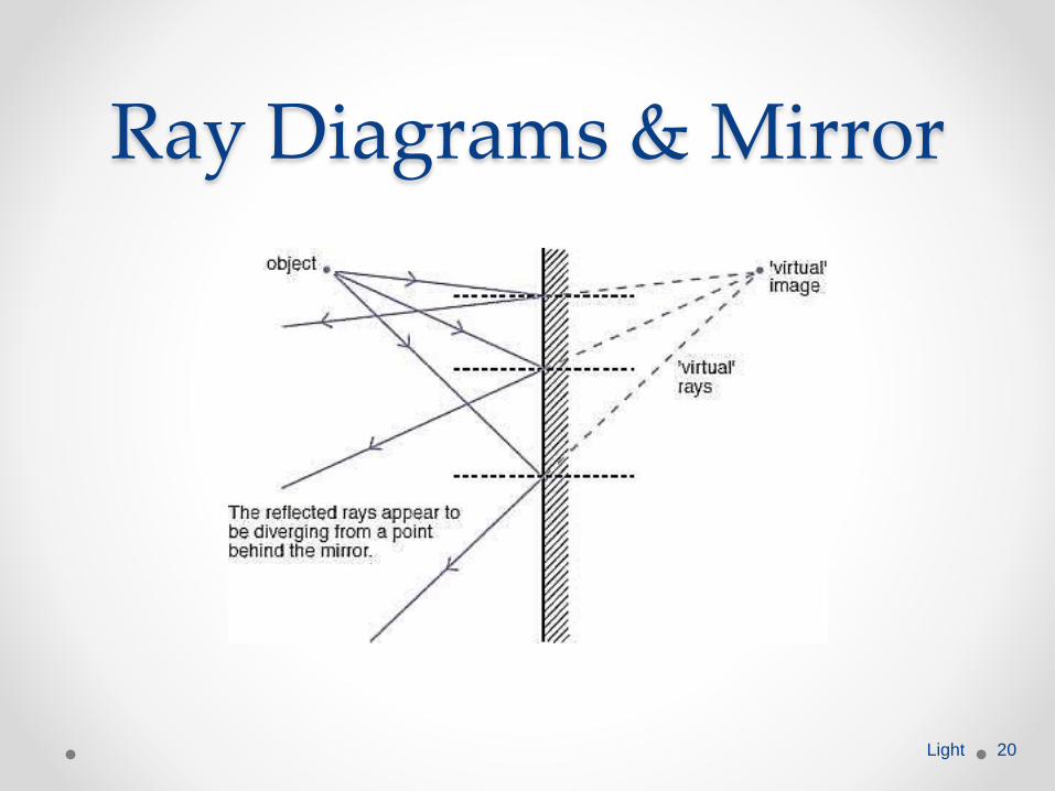
Ray Diagrams & Mirror
Light 20
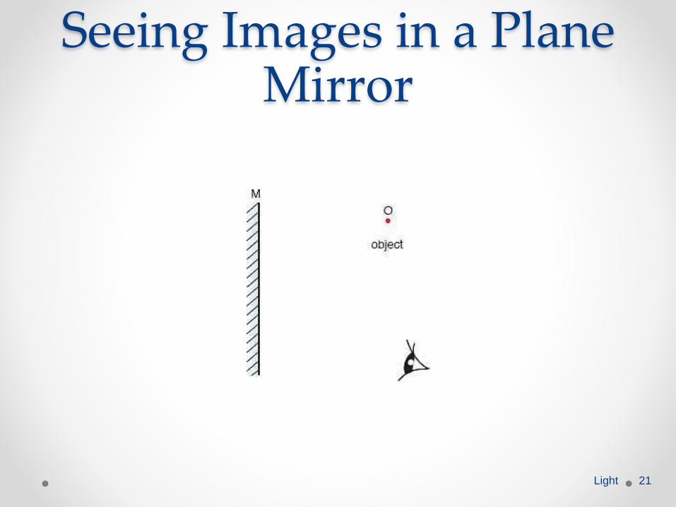
Seeing Images in a Plane Mirror
Light 21
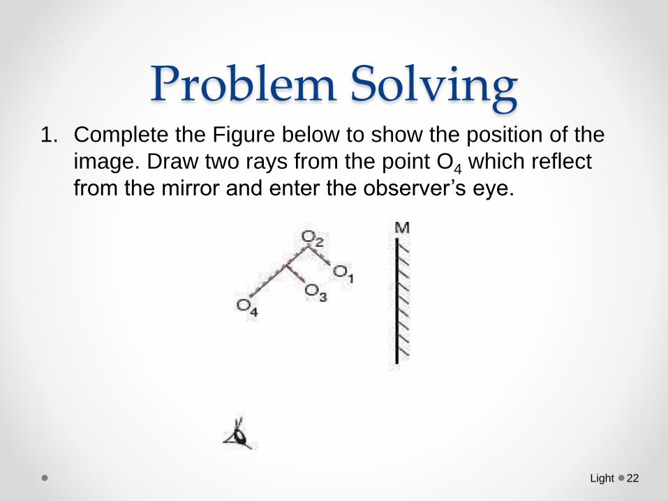
Problem Solving 1. Complete the Figure below to show the position of the
image. Draw two rays from the point O4 which reflect
from the mirror and enter the observer’s eye.
Light 22
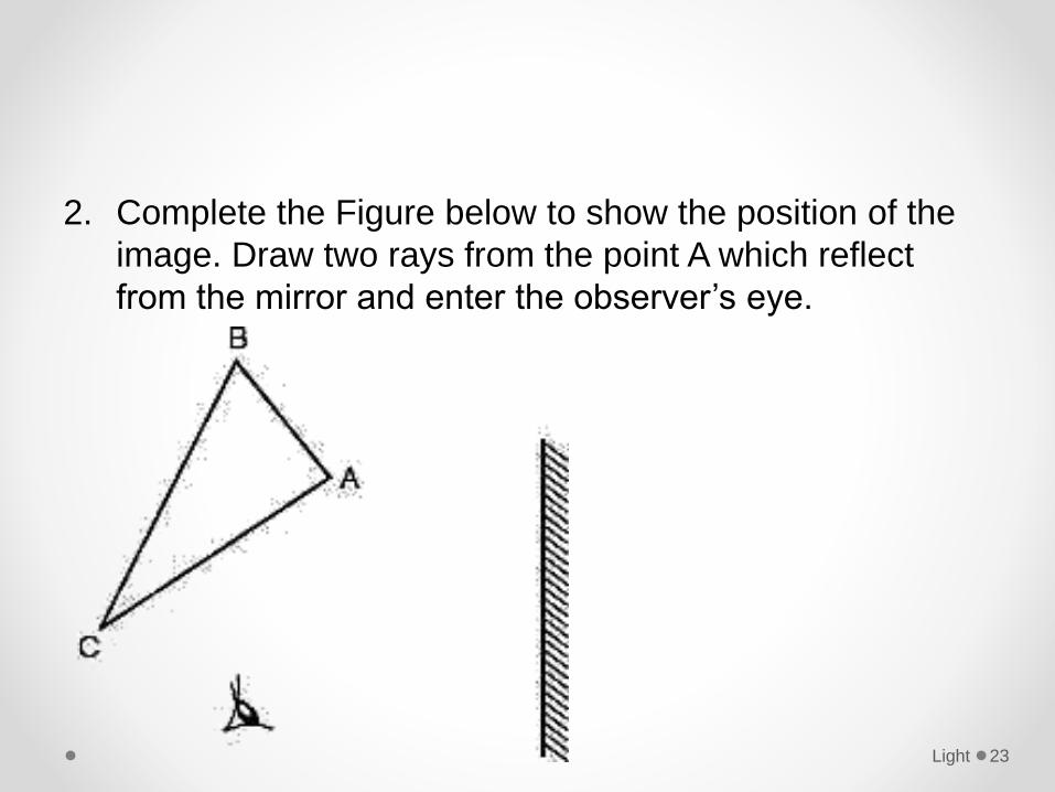
2. Complete the Figure below to show the position of the
image. Draw two rays from the point A which reflect
from the mirror and enter the observer’s eye.
Light 23
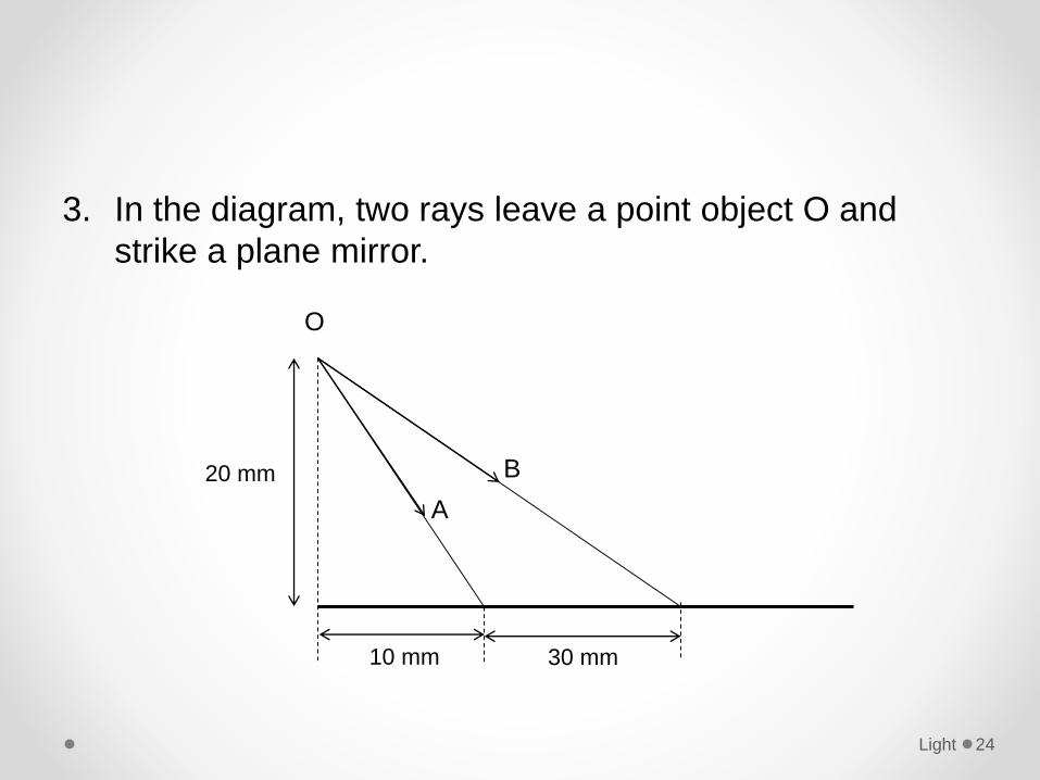
3. In the diagram, two rays leave a point object O and
strike a plane mirror.
Light 24
20 mm
10 mm 30 mm
O
A
B
a. Make an exact copy of the diagram.
b. Measure the angle of incidence of each ray.
c. Draw in the two reflected rays at the correct angles.
d. Find where the image formed and label it.
Light 25
4. Light strikes a mirror, making an angle of 25° to the
surface. What angle will the reflected light make with
the surface?
5. Light strikes a mirror, making an angle of 20° to the
surface. What is the angle of reflection?
6. Light leaving a mirror makes an angle of 42° with
respect to the normal to the surface. What was the
angle of incidence?
Light 26
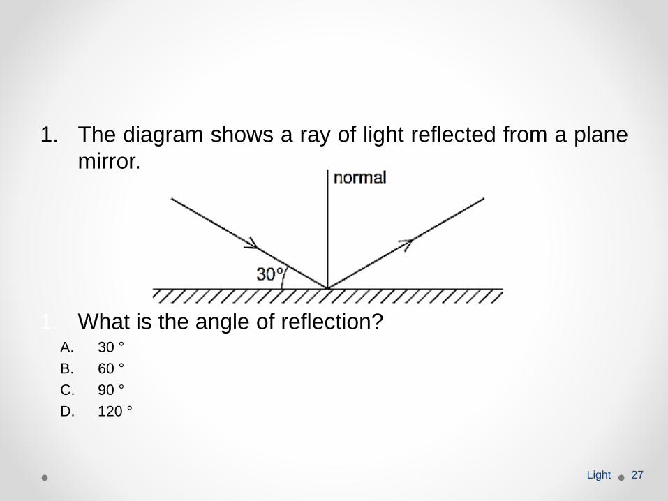
1. The diagram shows a ray of light reflected from a plane
mirror.
1. What is the angle of reflection?A. 30 °
B. 60 °
C. 90 °
D. 120 °
Light 27
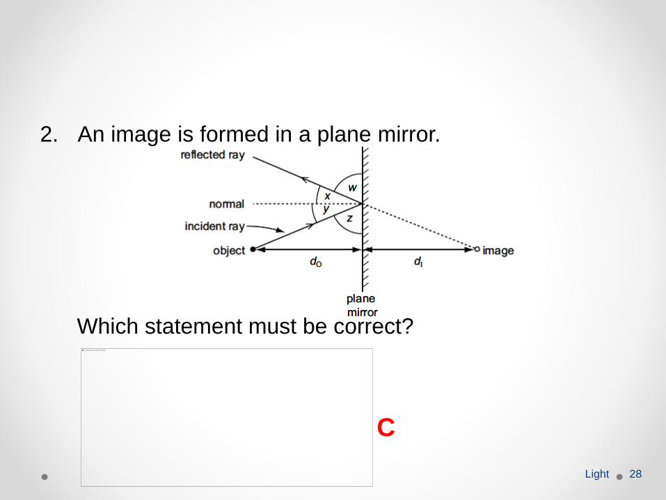
2. An image is formed in a plane mirror.
Which statement must be correct?
Light 28
C
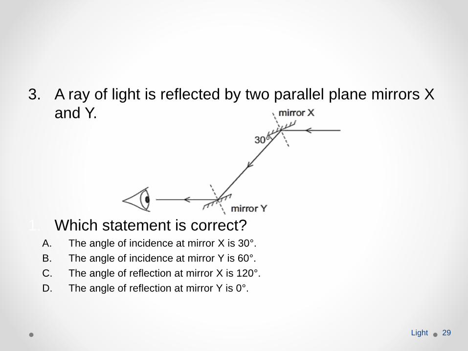
3. A ray of light is reflected by two parallel plane mirrors X
and Y.
1. Which statement is correct?A. The angle of incidence at mirror X is 30°.
B. The angle of incidence at mirror Y is 60°.
C. The angle of reflection at mirror X is 120°.
D. The angle of reflection at mirror Y is 0°.
Light 29
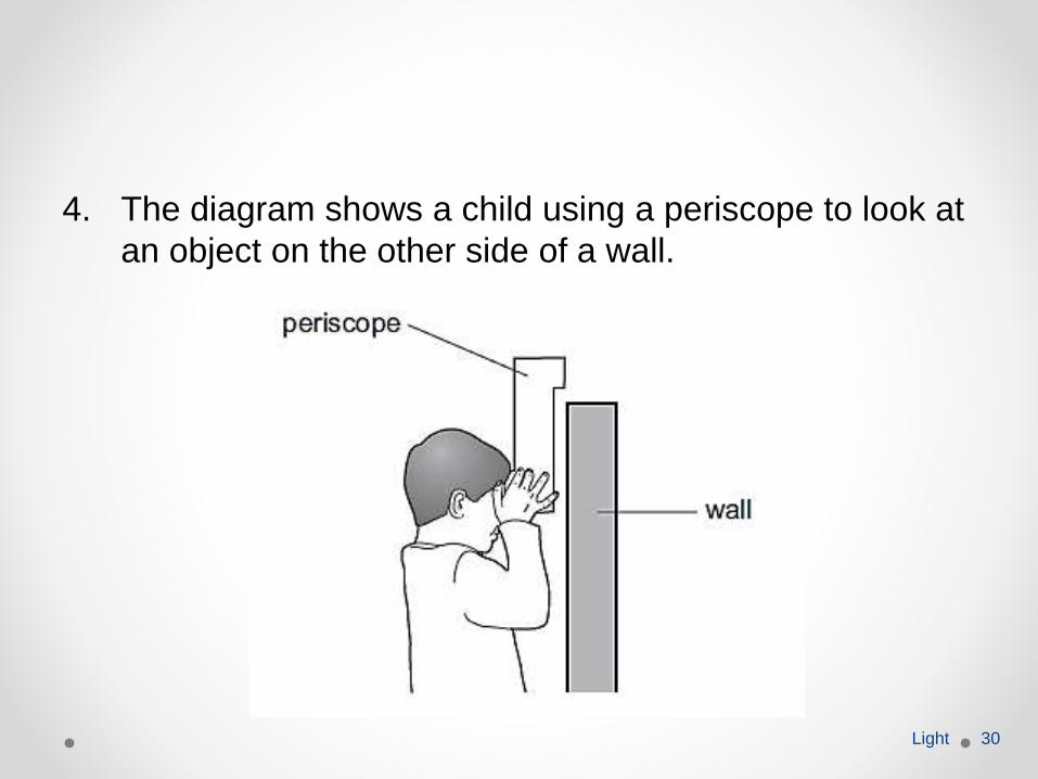
4. The diagram shows a child using a periscope to look at
an object on the other side of a wall.
Light 30
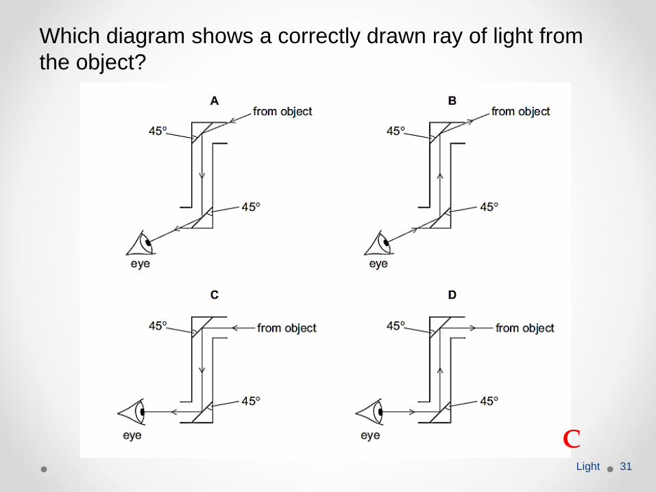
Which diagram shows a correctly drawn ray of light from
the object?
Light 31
C
5. Which characteristics describe an image formed in a
plane mirror?A. real and inverted
B. virtual and upright
C. real and larger than the object
D. virtual and smaller than the object
Light 32
6. A plane mirror is on a wall.
Which is a correct description of the image formed by
the mirror?A. the right way up and smaller than the object
B. the right way up and the same size as the object
C. upside down and smaller than the object
D. upside down and the same size as the object
Light 33
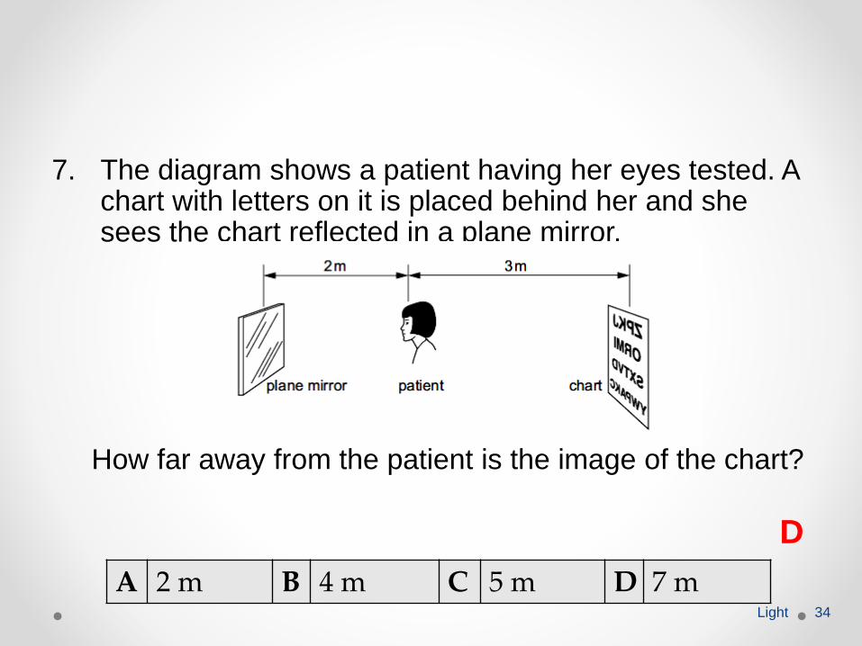
7. The diagram shows a patient having her eyes tested. A chart with letters on it is placed behind her and she sees the chart reflected in a plane mirror.
How far away from the patient is the image of the chart?
Light 34
A 2 m B 4 m C 5 m D 7 m
D
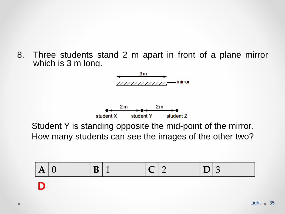
8. Three students stand 2 m apart in front of a plane mirrorwhich is 3 m long.
Student Y is standing opposite the mid-point of the mirror.
How many students can see the images of the other two?
Light 35
A 0 B 1 C 2 D 3
D
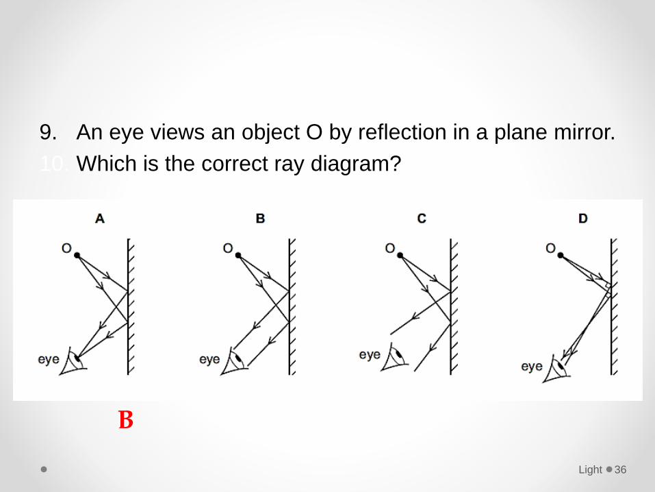
9. An eye views an object O by reflection in a plane mirror.
10. Which is the correct ray diagram?
Light 36
B
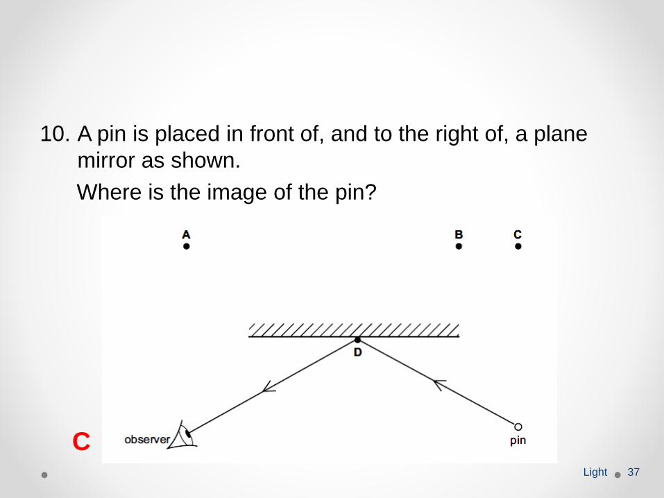
10. A pin is placed in front of, and to the right of, a plane
mirror as shown.
Where is the image of the pin?
Light 37
C
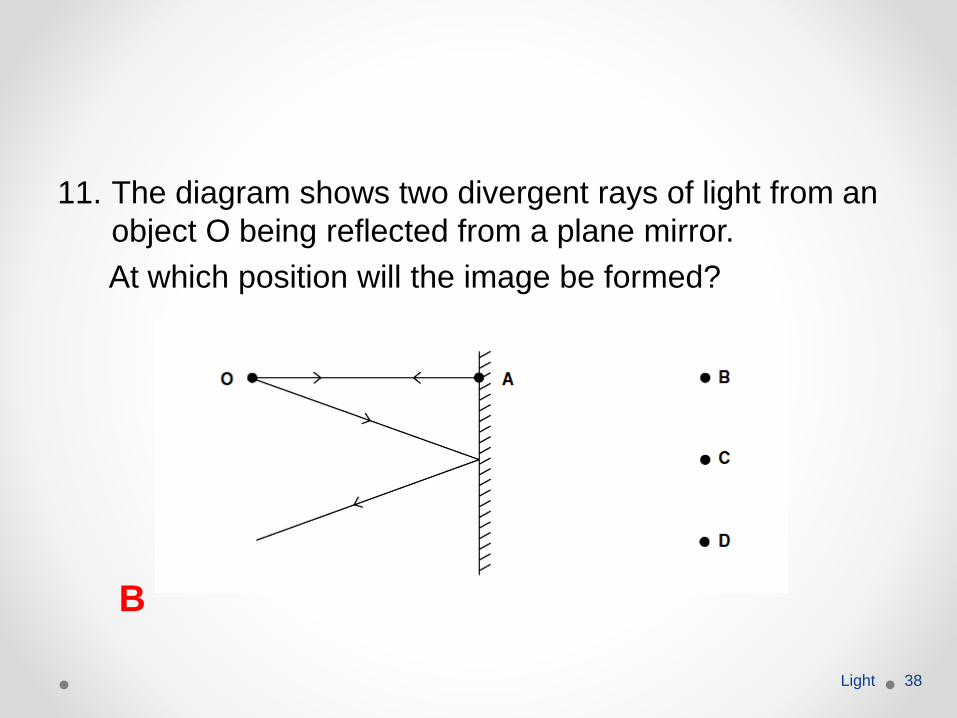
11. The diagram shows two divergent rays of light from an
object O being reflected from a plane mirror.
At which position will the image be formed?
Light 38
B
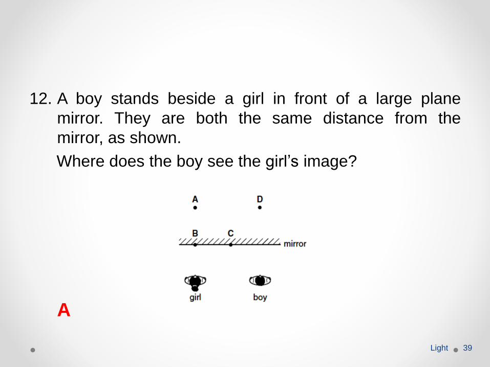
12. A boy stands beside a girl in front of a large plane
mirror. They are both the same distance from the
mirror, as shown.
Where does the boy see the girl’s image?
Light 39
A
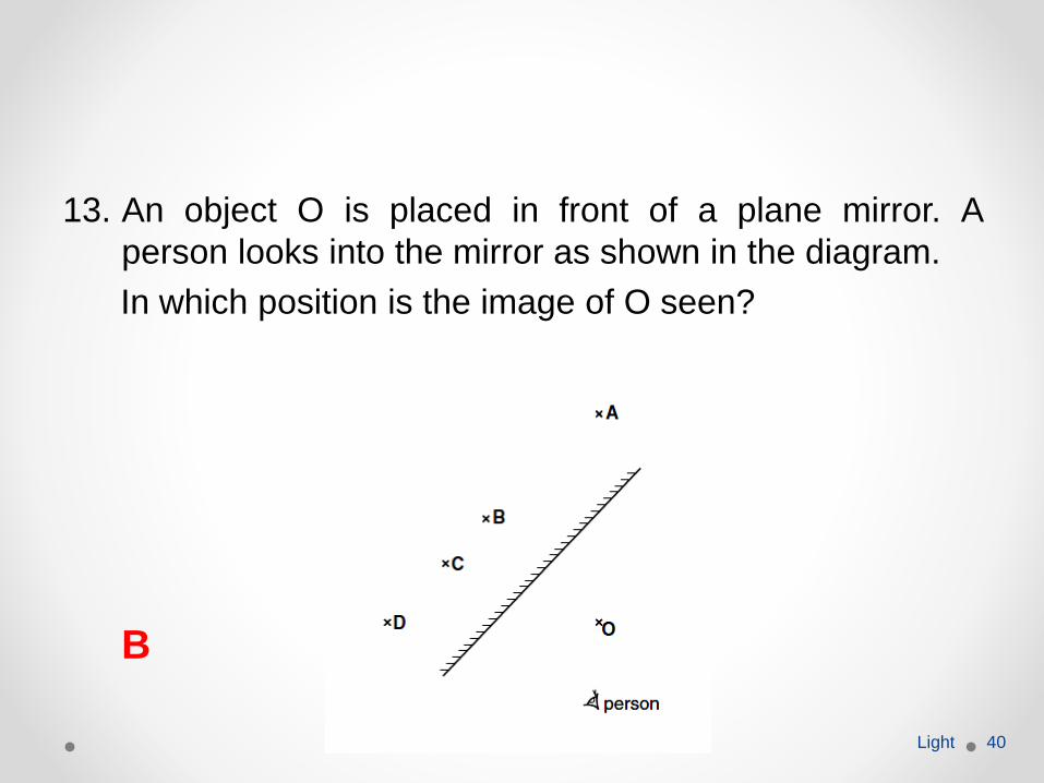
13. An object O is placed in front of a plane mirror. A
person looks into the mirror as shown in the diagram.
In which position is the image of O seen?
Light 40
B
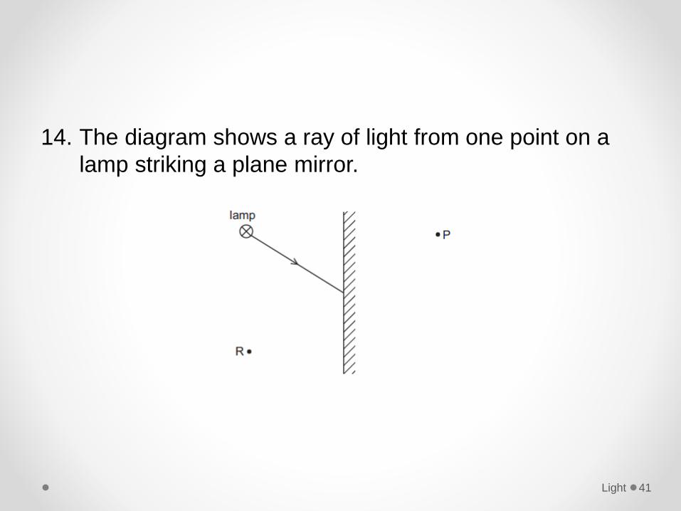
14. The diagram shows a ray of light from one point on a
lamp striking a plane mirror.
Light 41
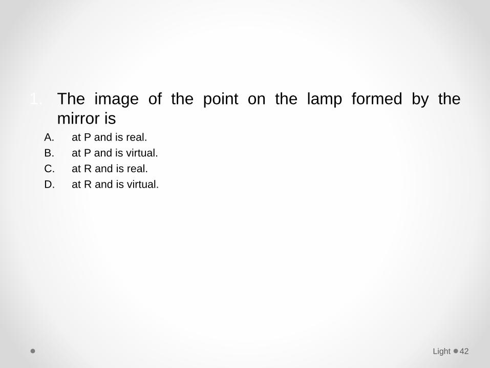
1. The image of the point on the lamp formed by the
mirror isA. at P and is real.
B. at P and is virtual.
C. at R and is real.
D. at R and is virtual.
Light 42
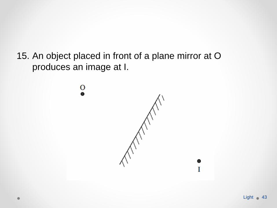
15. An object placed in front of a plane mirror at O
produces an image at I.
Light 43
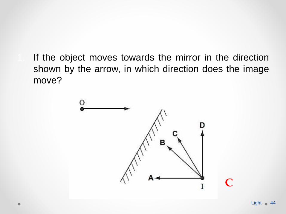
1. If the object moves towards the mirror in the direction
shown by the arrow, in which direction does the image
move?
Light 44
C
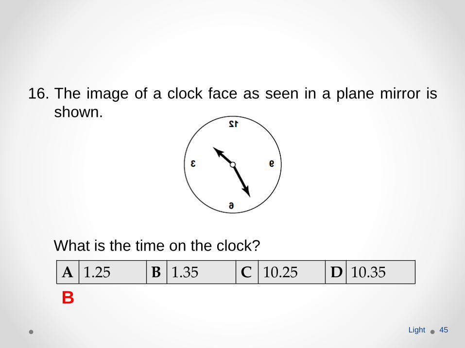
16. The image of a clock face as seen in a plane mirror is
shown.
What is the time on the clock?
Light 45
A 1.25 B 1.35 C 10.25 D 10.35
B
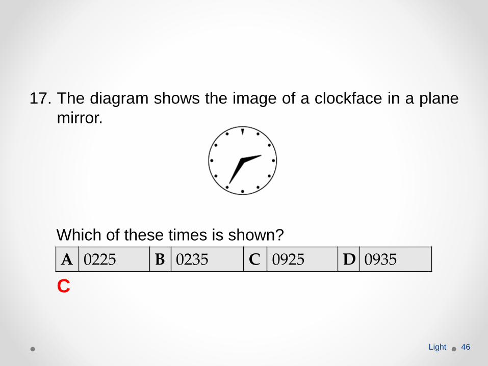
17. The diagram shows the image of a clockface in a plane
mirror.
Which of these times is shown?
Light 46
A 0225 B 0235 C 0925 D 0935
C
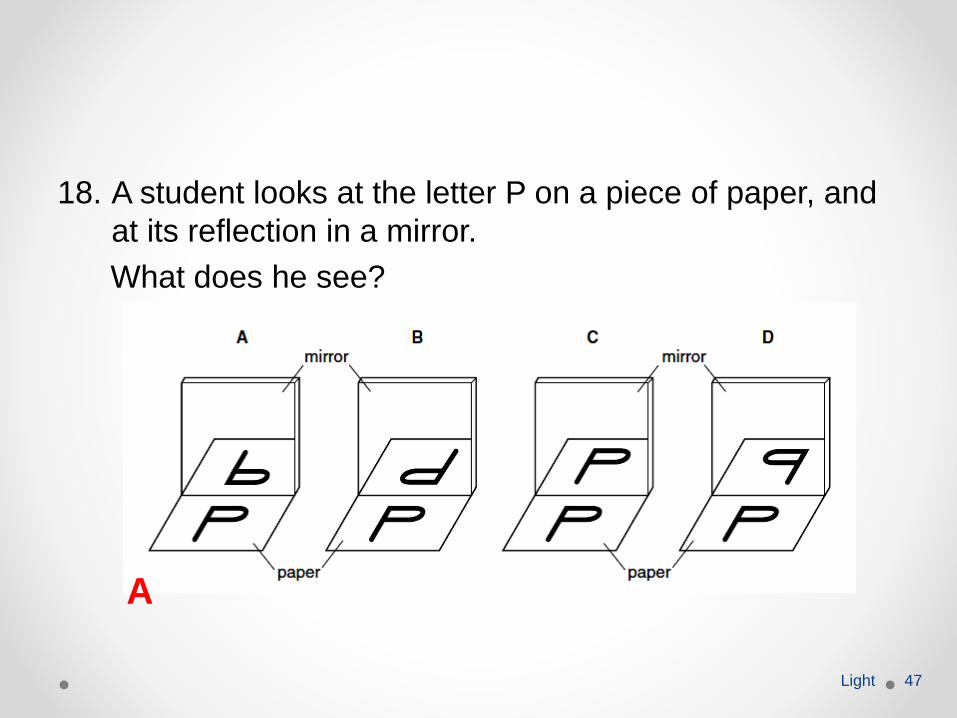
18. A student looks at the letter P on a piece of paper, and
at its reflection in a mirror.
What does he see?
Light 47
A
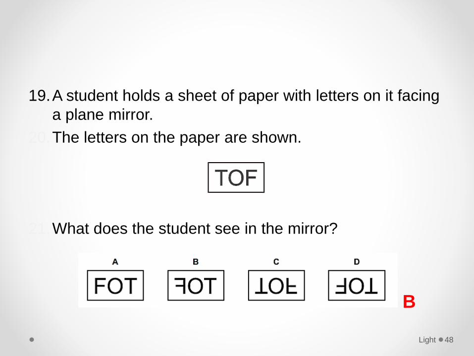
19.A student holds a sheet of paper with letters on it facing
a plane mirror.
20.The letters on the paper are shown.
21.What does the student see in the mirror?
Light 48
B
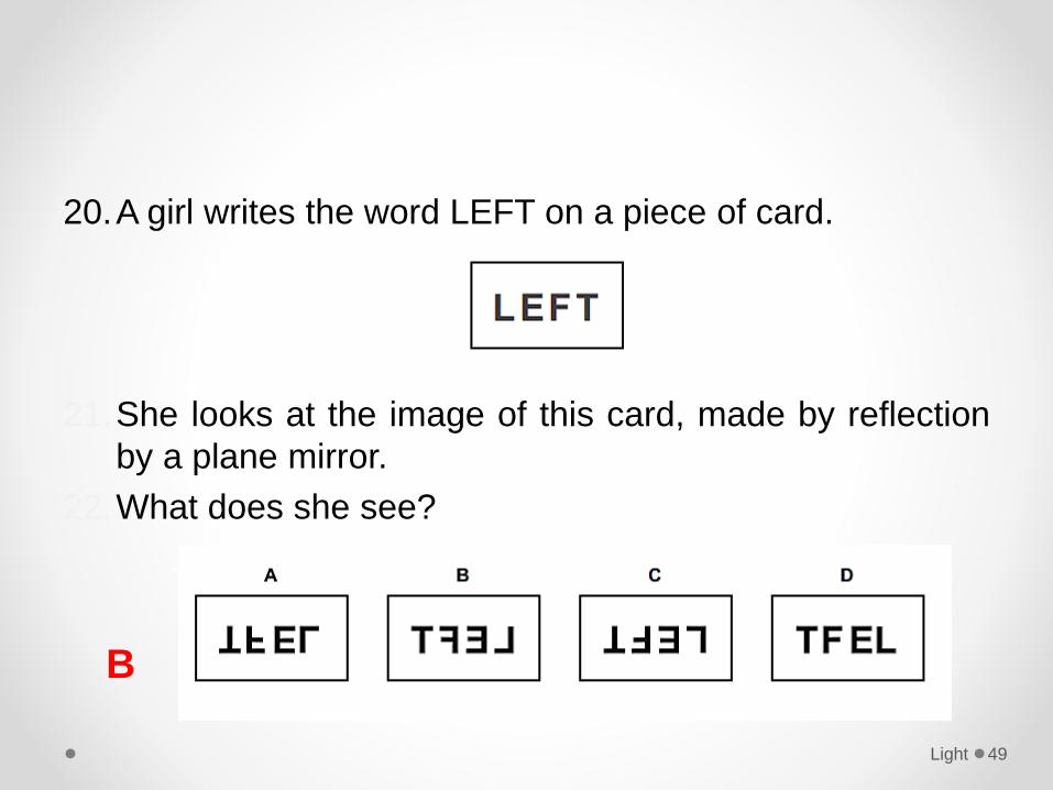
20.A girl writes the word LEFT on a piece of card.
21.She looks at the image of this card, made by reflection
by a plane mirror.
22.What does she see?
Light 49
B
Refraction of lightDefine the terms used in refraction including angle of incidence, angle of refraction and refractive index.
Light 50
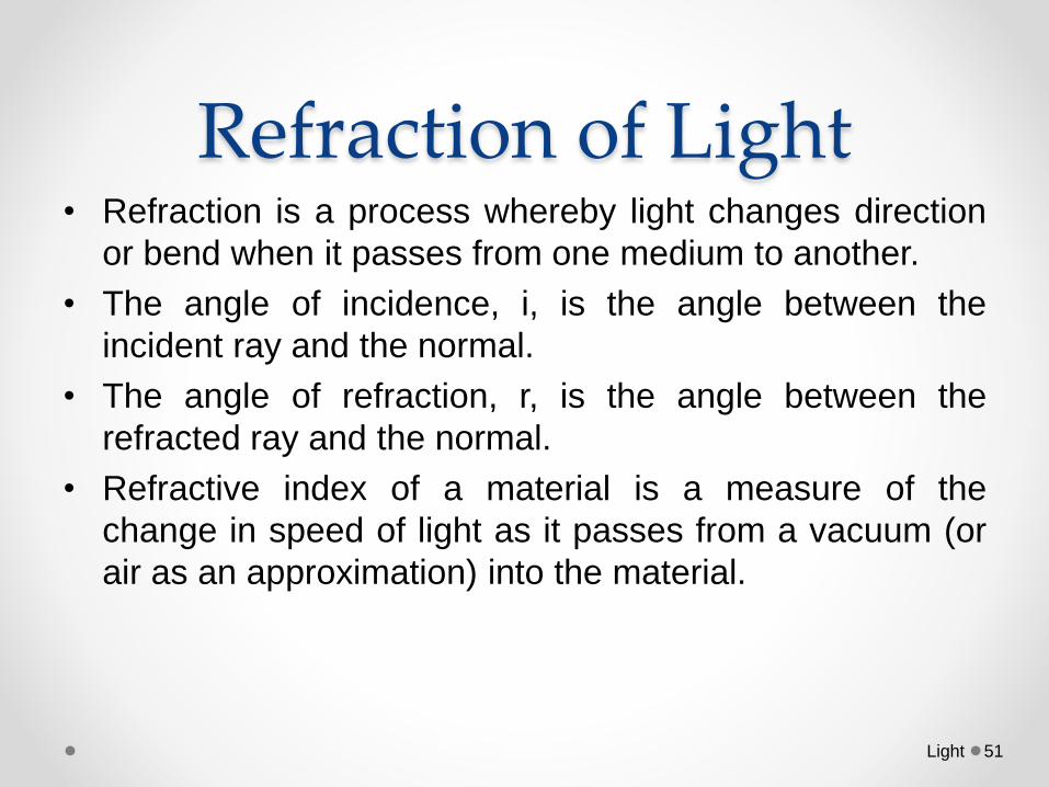
Refraction of Light• Refraction is a process whereby light changes direction
or bend when it passes from one medium to another.
• The angle of incidence, i, is the angle between the
incident ray and the normal.
• The angle of refraction, r, is the angle between the
refracted ray and the normal.
• Refractive index of a material is a measure of the
change in speed of light as it passes from a vacuum (or
air as an approximation) into the material.
Light 51
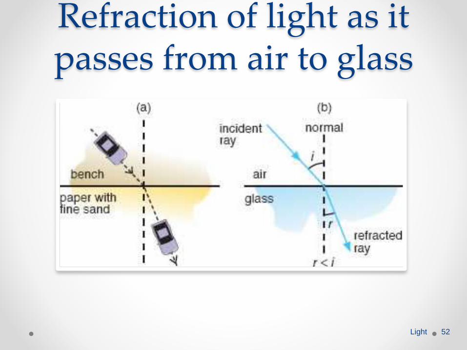
Refraction of light as it passes from air to glass
Light 52
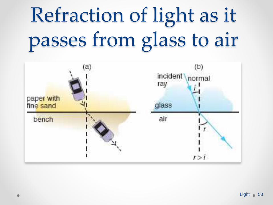
Refraction of light as it passes from glass to air
Light 53
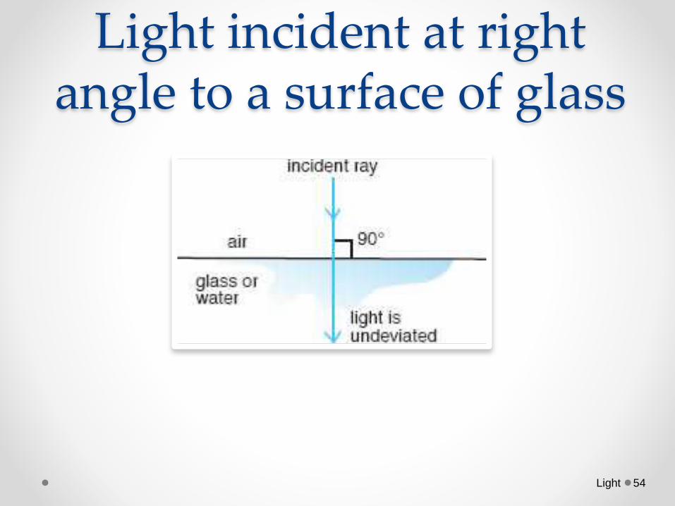
Light incident at right angle to a surface of glass
Light 54
Refraction of lightDescribe experiments to show refraction of light
through glass blocks.
Light 55
• Aim: To determine the refractive index of glass, using a
glass block
• Apparatus:o Rectangular glass block
o Ray box
Light 56
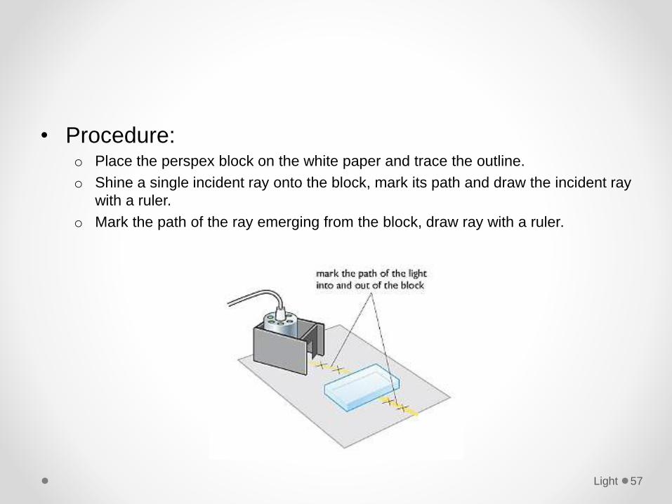
• Procedure:o Place the perspex block on the white paper and trace the outline.
o Shine a single incident ray onto the block, mark its path and draw the incident ray
with a ruler.
o Mark the path of the ray emerging from the block, draw ray with a ruler.
Light 57
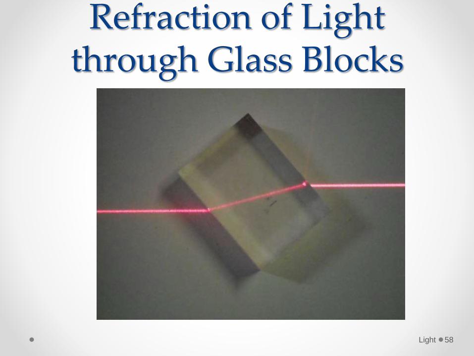
Refraction of Light through Glass Blocks
Light 58
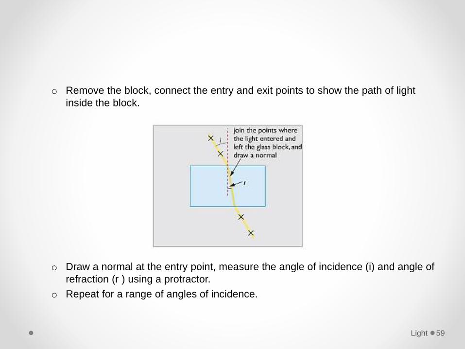
o Remove the block, connect the entry and exit points to show the path of light
inside the block.
o Draw a normal at the entry point, measure the angle of incidence (i) and angle of
refraction (r ) using a protractor.
o Repeat for a range of angles of incidence.
Light 59
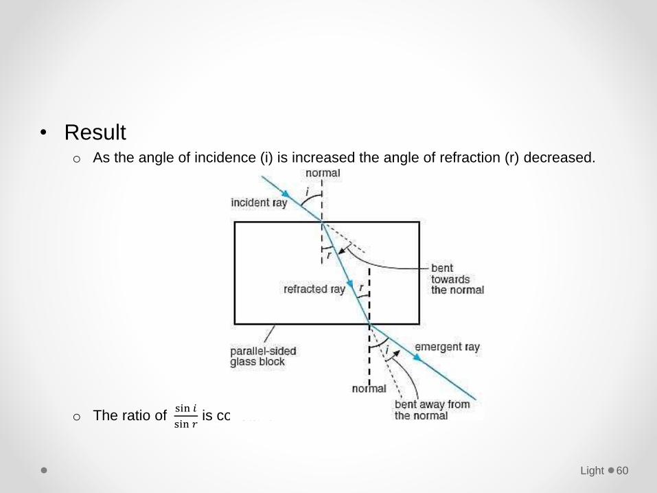
• Resulto As the angle of incidence (i) is increased the angle of refraction (r) decreased.
o The ratio of sin 𝑖
sin 𝑟is constant.
Light 60
Refraction of lightDo calculations using the equation sin i /sin r =
constant.
Light 61
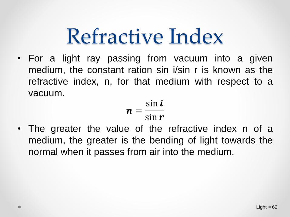
Refractive Index• For a light ray passing from vacuum into a given
medium, the constant ration sin i/sin r is known as the
refractive index, n, for that medium with respect to a
vacuum.
𝒏 =sin 𝒊
sin 𝒓• The greater the value of the refractive index n of a
medium, the greater is the bending of light towards the
normal when it passes from air into the medium.
Light 62
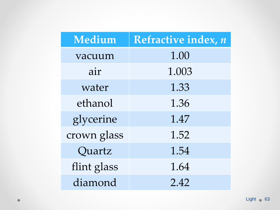
Medium Refractive index, n
vacuum 1.00
air 1.003
water 1.33
ethanol 1.36
glycerine 1.47
crown glass 1.52
Quartz 1.54
flint glass 1.64
diamond 2.42
Light 63
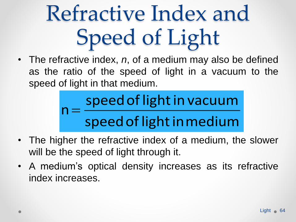
Refractive Index and Speed of Light
• The refractive index, n, of a medium may also be defined
as the ratio of the speed of light in a vacuum to the
speed of light in that medium.
• The higher the refractive index of a medium, the slower
will be the speed of light through it.
• A medium’s optical density increases as its refractive
index increases.
Light 64
medium in lightof speed
vacuum in lightof speedn
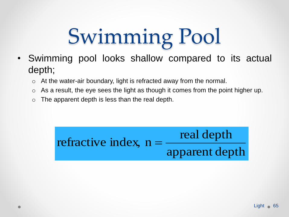
Swimming Pool• Swimming pool looks shallow compared to its actual
depth;o At the water-air boundary, light is refracted away from the normal.
o As a result, the eye sees the light as though it comes from the point higher up.
o The apparent depth is less than the real depth.
Light 65
depthapparent
depth realn index, refractive
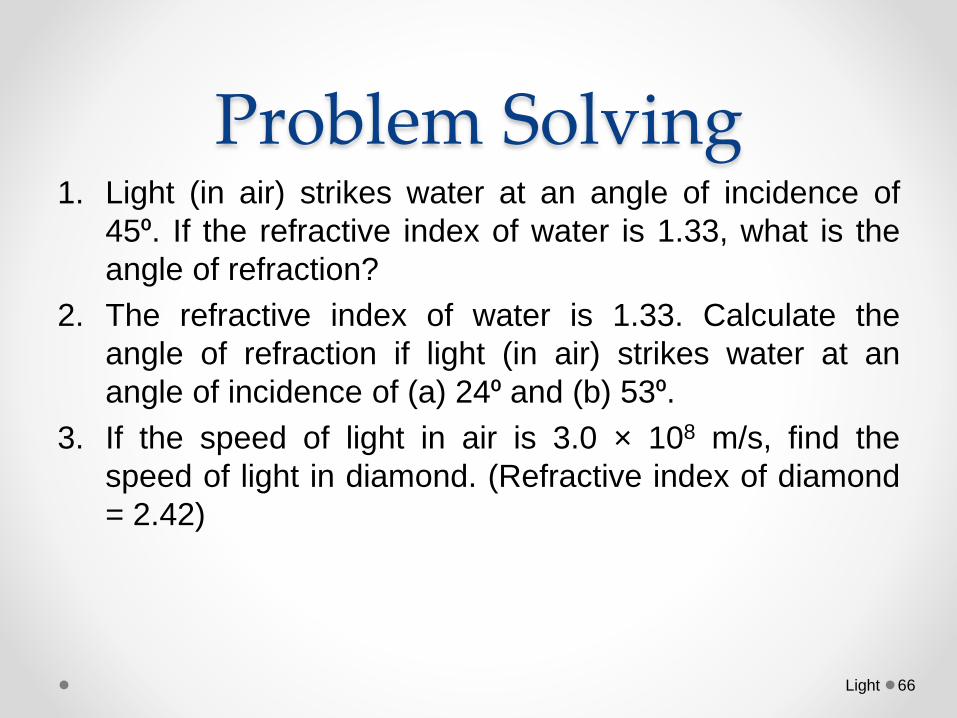
Problem Solving 1. Light (in air) strikes water at an angle of incidence of
45⁰. If the refractive index of water is 1.33, what is the
angle of refraction?
2. The refractive index of water is 1.33. Calculate the
angle of refraction if light (in air) strikes water at an
angle of incidence of (a) 24⁰ and (b) 53⁰.
3. If the speed of light in air is 3.0 × 10⁸ m/s, find the
speed of light in diamond. (Refractive index of diamond
= 2.42)
Light 66
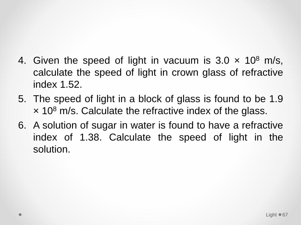
4. Given the speed of light in vacuum is 3.0 × 10⁸ m/s,
calculate the speed of light in crown glass of refractive
index 1.52.
5. The speed of light in a block of glass is found to be 1.9
× 108 m/s. Calculate the refractive index of the glass.
6. A solution of sugar in water is found to have a refractive
index of 1.38. Calculate the speed of light in the
solution.
Light 67
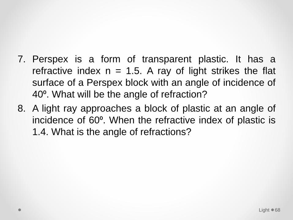
7. Perspex is a form of transparent plastic. It has a
refractive index n = 1.5. A ray of light strikes the flat
surface of a Perspex block with an angle of incidence of
40⁰. What will be the angle of refraction?
8. A light ray approaches a block of plastic at an angle of
incidence of 60⁰. When the refractive index of plastic is
1.4. What is the angle of refractions?
Light 68
Refraction of lightDefine the terms critical angle and total internal
reflection.
Light 69
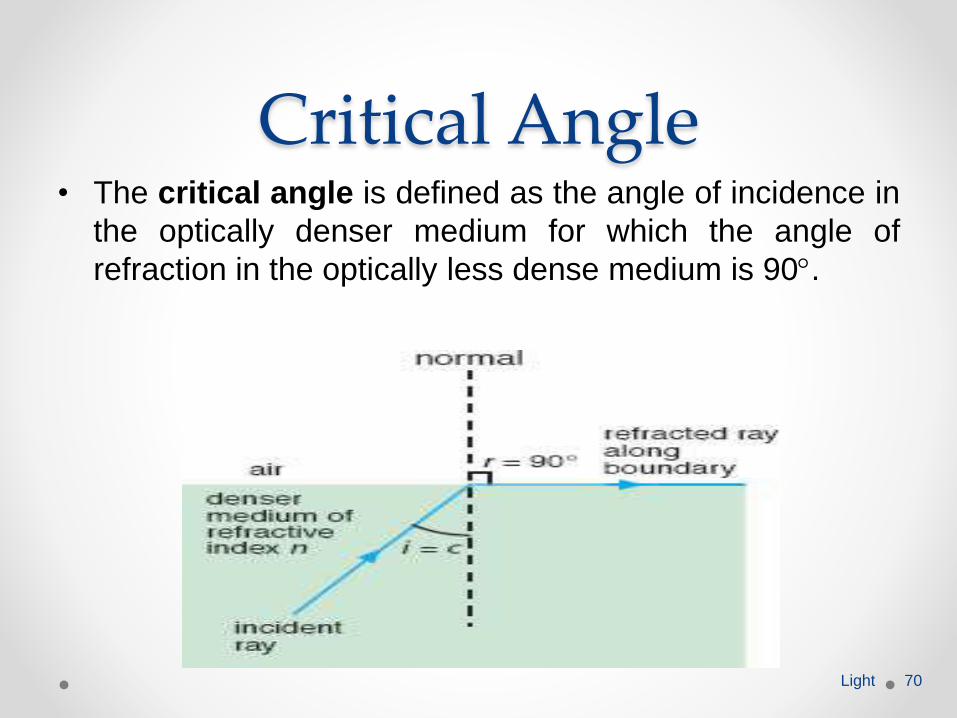
Critical Angle• The critical angle is defined as the angle of incidence in
the optically denser medium for which the angle of
refraction in the optically less dense medium is 90.
Light 70
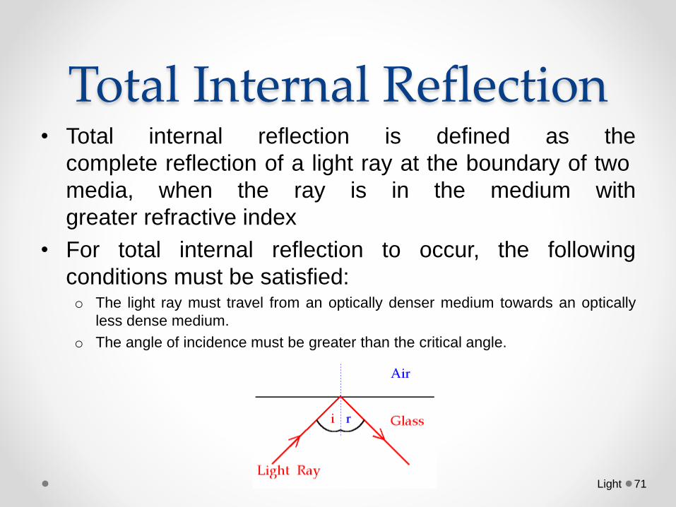
Total Internal Reflection• Total internal reflection is defined as the
complete reflection of a light ray at the boundary of two
media, when the ray is in the medium with
greater refractive index
• For total internal reflection to occur, the following
conditions must be satisfied:o The light ray must travel from an optically denser medium towards an optically
less dense medium.
o The angle of incidence must be greater than the critical angle.
Light 71
Light 72
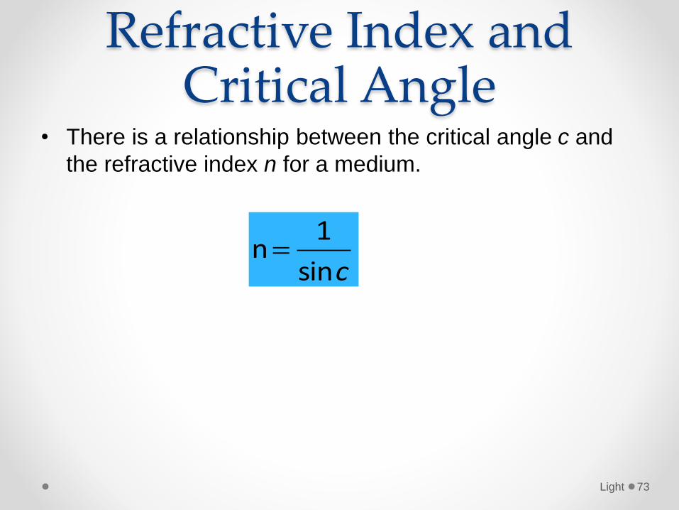
Refractive Index and Critical Angle
• There is a relationship between the critical angle c and
the refractive index n for a medium.
Light 73
csin
1n
Example1. Calculate the critical angle for
a. Glass of refractive index 1.50,
b. Water of refractive index 1.33,
2. A transparent material has a refractive index of 2.0.
calculate the critical angle.
3. Diamond has a refractive index of 2.42. The speed of
light in a vacuum (or in air) is 3.0 × 10⁸ m/s. Calculate:a. the speed of light in diamond
b. critical angle for diamond.
4. A glass prism is made of glass or refractive index, n =
1.9. Determine the critical angle of the glass.
Light 74
Refraction of lightDescribe experiments to show total internal
reflection.
Light 75
• Aim: To show total internal reflection
• Apparatus:o Semi-circular glass block
o Ray box
o Protractor
Light 76
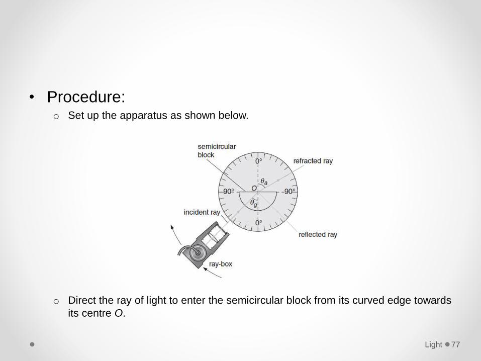
• Procedure:o Set up the apparatus as shown below.
o Direct the ray of light to enter the semicircular block from its curved edge towards
its centre O.
Light 77
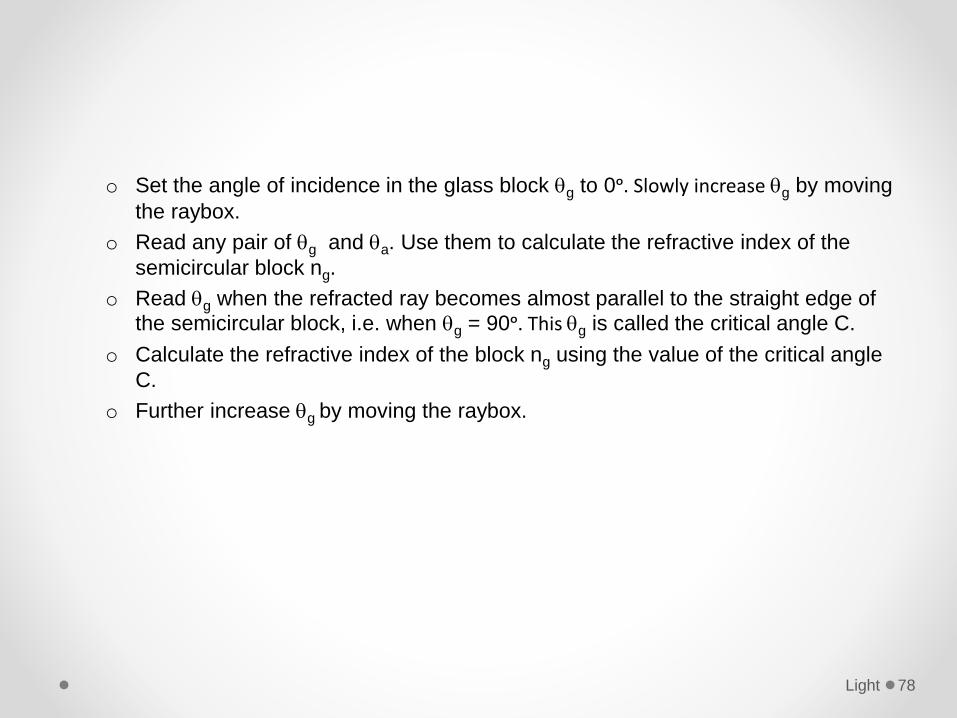
o Set the angle of incidence in the glass block g to 0ᵒ. Slowly increase g by moving
the raybox.
o Read any pair of g and a. Use them to calculate the refractive index of the
semicircular block ng.
o Read g when the refracted ray becomes almost parallel to the straight edge of
the semicircular block, i.e. when g = 90ᵒ. This g is called the critical angle C.
o Calculate the refractive index of the block ng using the value of the critical angle
C.
o Further increase g by moving the raybox.
Light 78
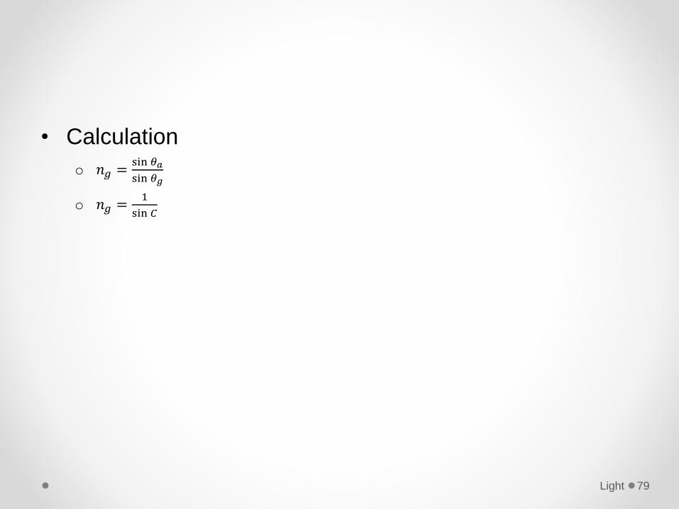
• Calculation
o 𝑛𝑔 =sin 𝜃𝑎
sin 𝜃𝑔
o 𝑛𝑔 =1
sin 𝐶
Light 79
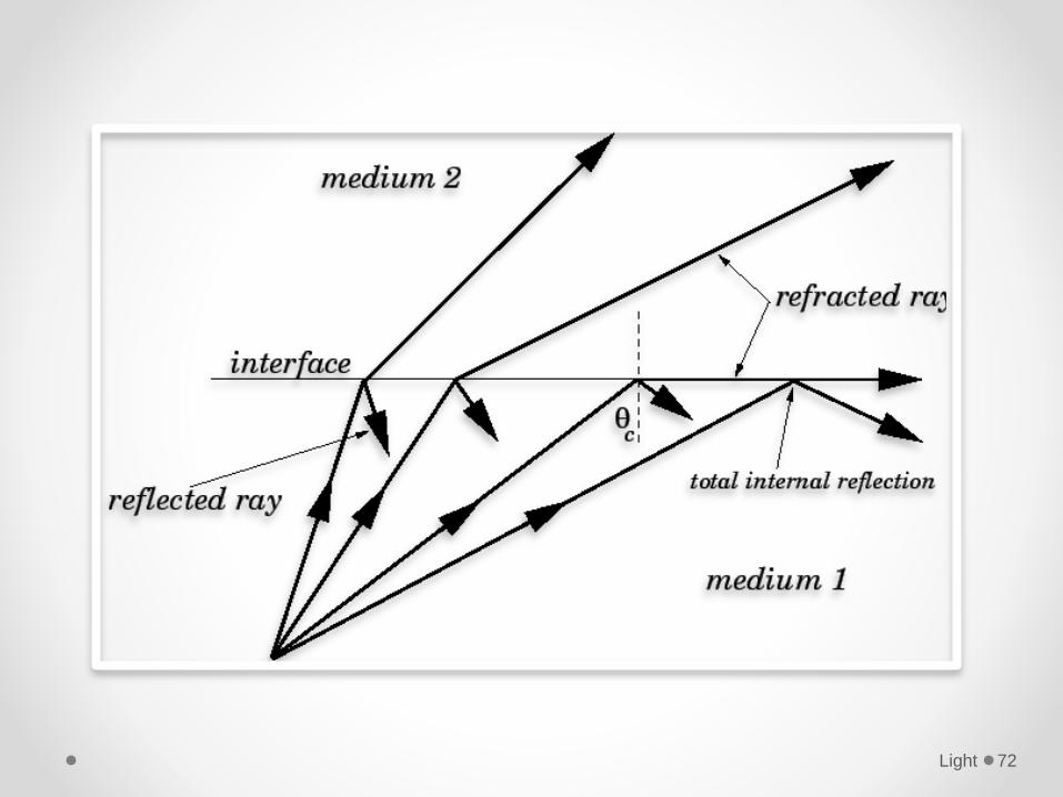
• Resulto When g increases, the refracted ray moves away from the normal.
o When g is greater than the critical angle C, the ray is totally internally reflected.
Light 80
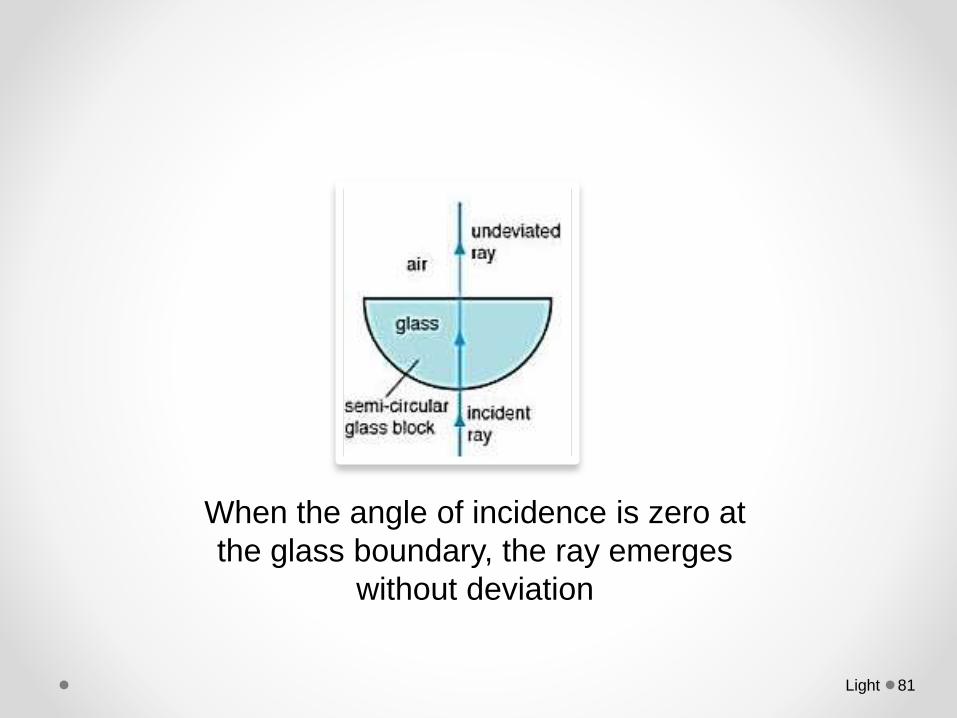
When the angle of incidence is zero at
the glass boundary, the ray emerges
without deviation
Light 81
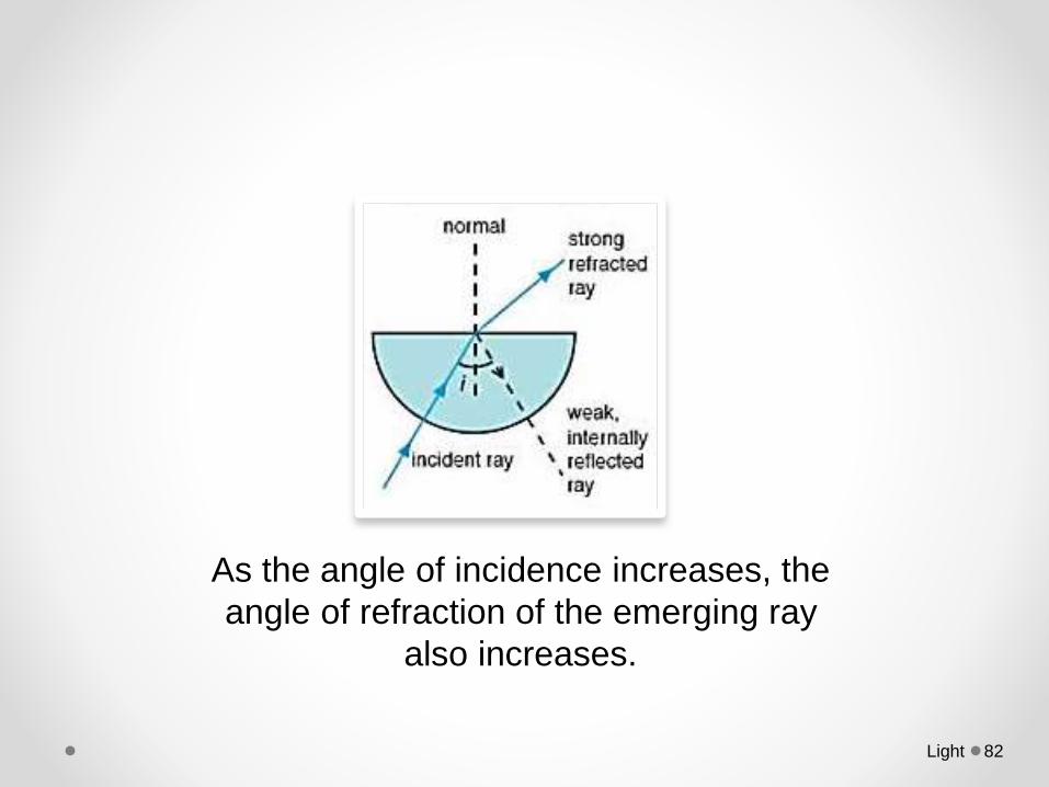
As the angle of incidence increases, the
angle of refraction of the emerging ray
also increases.
Light 82
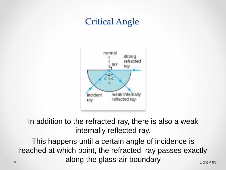
Critical Angle
In addition to the refracted ray, there is also a weak
internally reflected ray.
This happens until a certain angle of incidence is
reached at which point, the refracted ray passes exactly
along the glass-air boundary Light 83
Total Internal Reflection
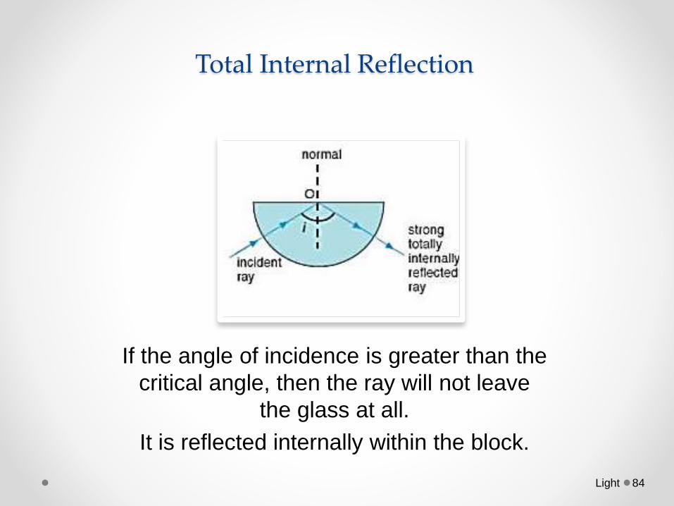
If the angle of incidence is greater than the
critical angle, then the ray will not leave
the glass at all.
It is reflected internally within the block.
Light 84
Refraction of lightDescribe the use of optical fibres intelecommunications and state the advantages oftheir use.
Light 85
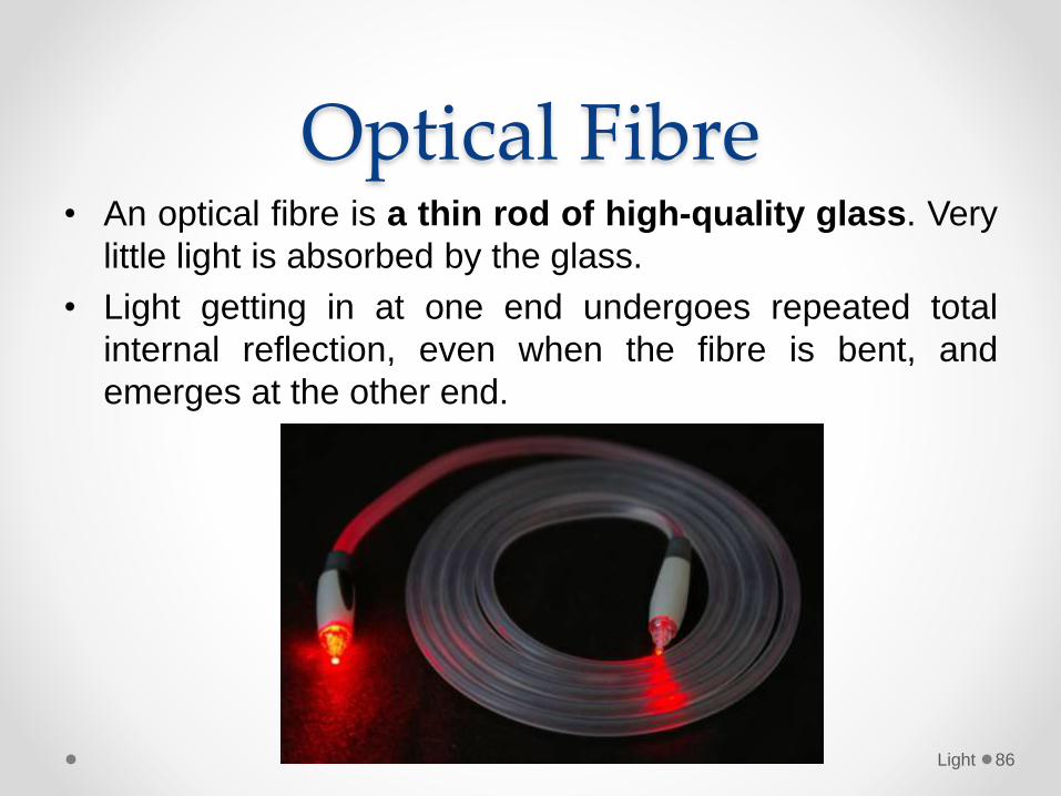
Optical Fibre• An optical fibre is a thin rod of high-quality glass. Very
little light is absorbed by the glass.
• Light getting in at one end undergoes repeated total
internal reflection, even when the fibre is bent, and
emerges at the other end.
Light 86
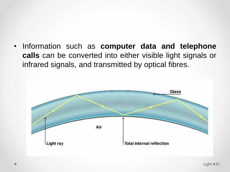
• Information such as computer data and telephone
calls can be converted into either visible light signals or
infrared signals, and transmitted by optical fibres.
Light 87
Advantage of Fibre Optics• Less expensive - can be made cheaper because of
glass are abundant.
• Thinner - Optical fibers can be drawn to smallerdiameters than copper wire.
• Higher carrying capacity- More fibres can be bundledinto a given-diameter cable than copper wires.
• Less signal degradation - The loss of signal in opticalfiber is less.
• Low interference - Light signals from one fiber do notinterfere with those of other fibers in the same cable.
Light 88
• Low power - Because signals in optical fibres degradeless, lower-power transmitters can be used.
• Digital signals - Optical fibers are ideally suited forcarrying digital information, which is especially useful incomputer networks.
• Non-flammable - Because no electricity is passedthrough optical fibers, there is no fire hazard.
• Lightweight - An optical cable weighs less than acomparable copper wire cable.
• Flexible - Because fiber optics are so flexible and cantransmit and receive light.
Light 89
1. What causes refraction when light travels from air into
glass?A. The amplitude of the light waves changes.
B. The colour of the light changes.
C. The frequency of the light waves changes.
D. The speed of the light changes.
Light 90
2. What happens to light as it passes from glass into air?A. Its frequency decreases because its speed decreases.
B. Its frequency increases because its speed increases.
C. Its wavelength decreases because its speed decreases.
D. Its wavelength increases because its speed increases.
Light 91
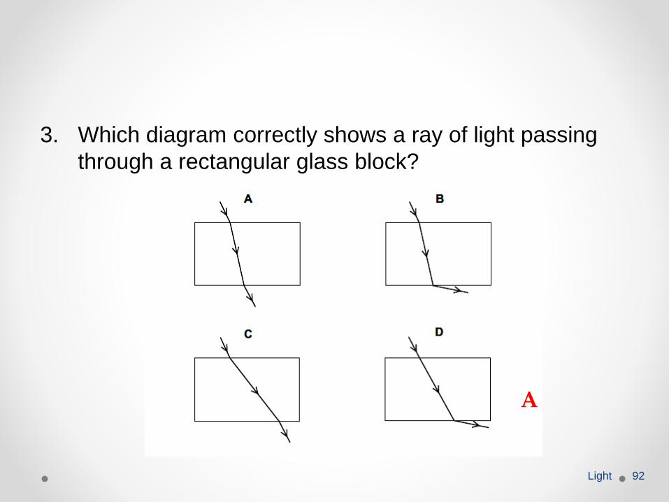
3. Which diagram correctly shows a ray of light passing
through a rectangular glass block?
Light 92
A
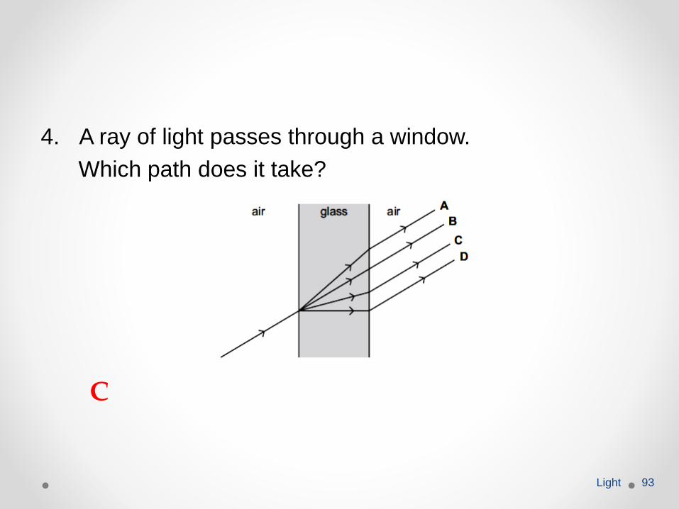
4. A ray of light passes through a window.
Which path does it take?
Light 93
C
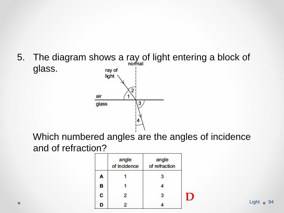
5. The diagram shows a ray of light entering a block of
glass.
Which numbered angles are the angles of incidence
and of refraction?
Light 94D
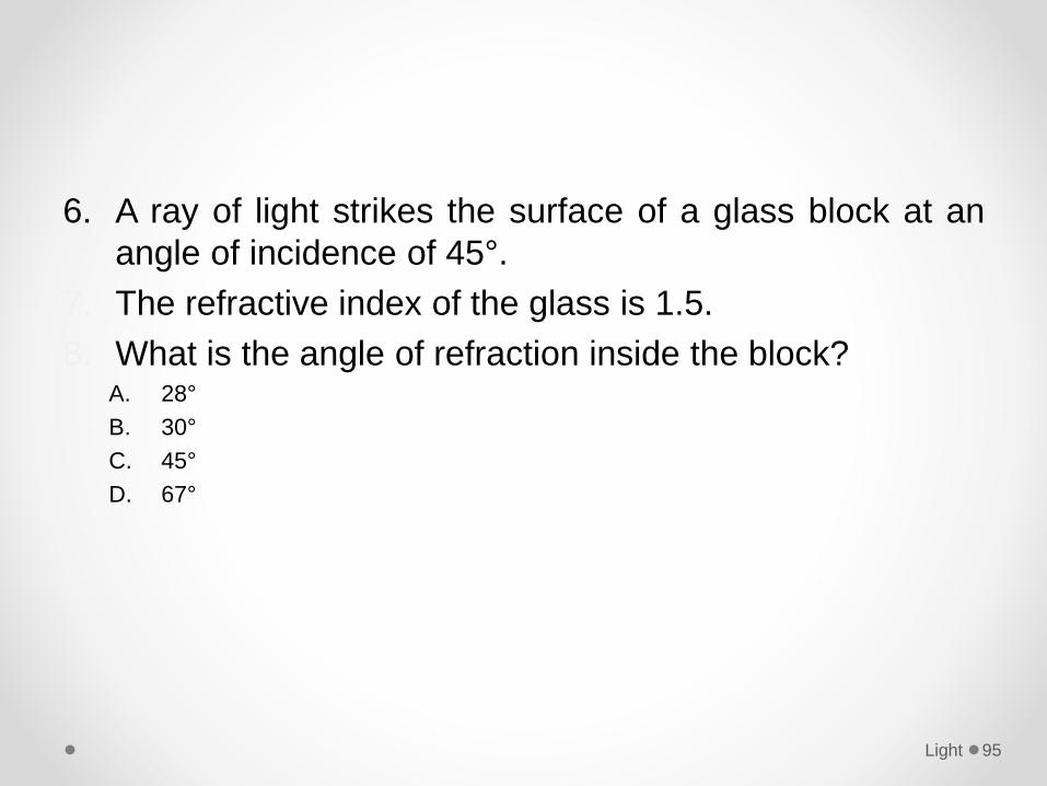
6. A ray of light strikes the surface of a glass block at an
angle of incidence of 45°.
7. The refractive index of the glass is 1.5.
8. What is the angle of refraction inside the block?A. 28°
B. 30°
C. 45°
D. 67°
Light 95
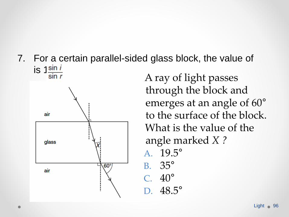
7. For a certain parallel-sided glass block, the value of
is 1.50.
Light 96
A ray of light passes through the block and emerges at an angle of 60°
to the surface of the block.What is the value of the angle marked X ?A. 19.5°
B. 35°
C. 40°
D. 48.5°
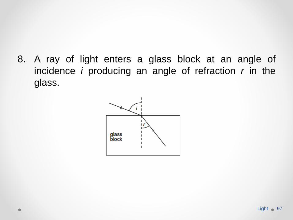
8. A ray of light enters a glass block at an angle of
incidence i producing an angle of refraction r in the
glass.
Light 97
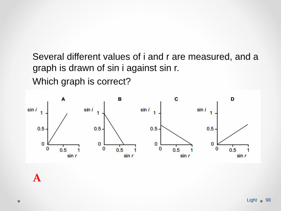
Several different values of i and r are measured, and a
graph is drawn of sin i against sin r.
Which graph is correct?
Light 98
A
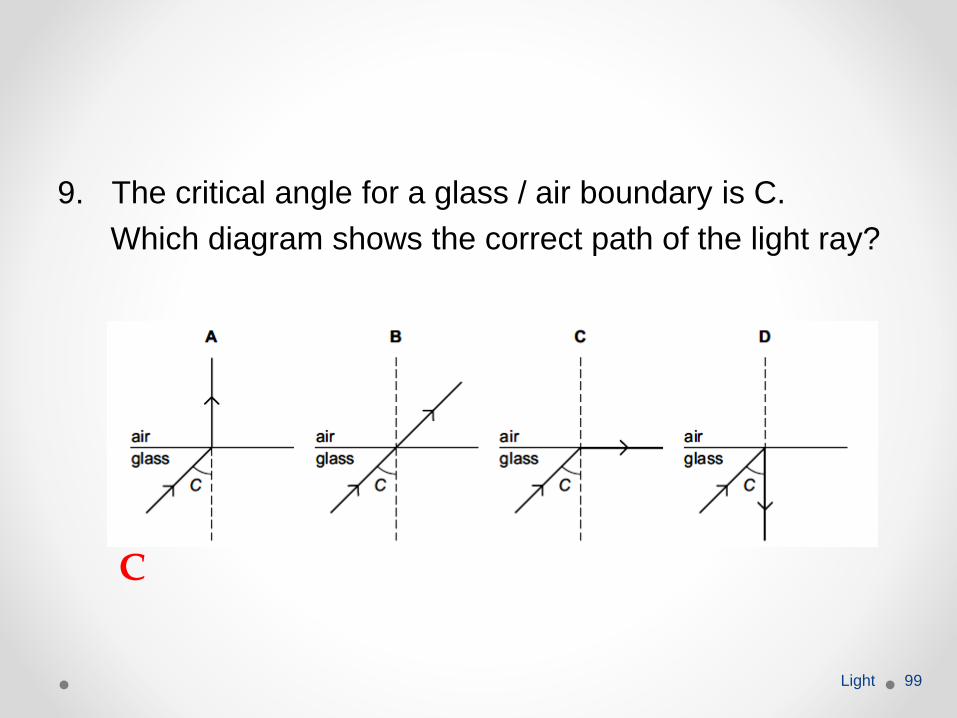
9. The critical angle for a glass / air boundary is C.
Which diagram shows the correct path of the light ray?
Light 99
C
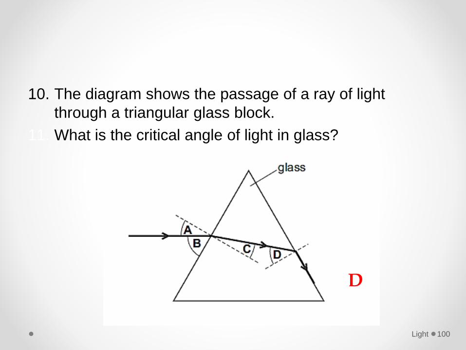
10. The diagram shows the passage of a ray of light
through a triangular glass block.
11. What is the critical angle of light in glass?
Light 100
D
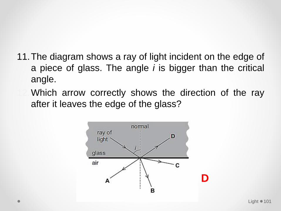
11.The diagram shows a ray of light incident on the edge of
a piece of glass. The angle i is bigger than the critical
angle.
12.Which arrow correctly shows the direction of the ray
after it leaves the edge of the glass?
Light 101
D
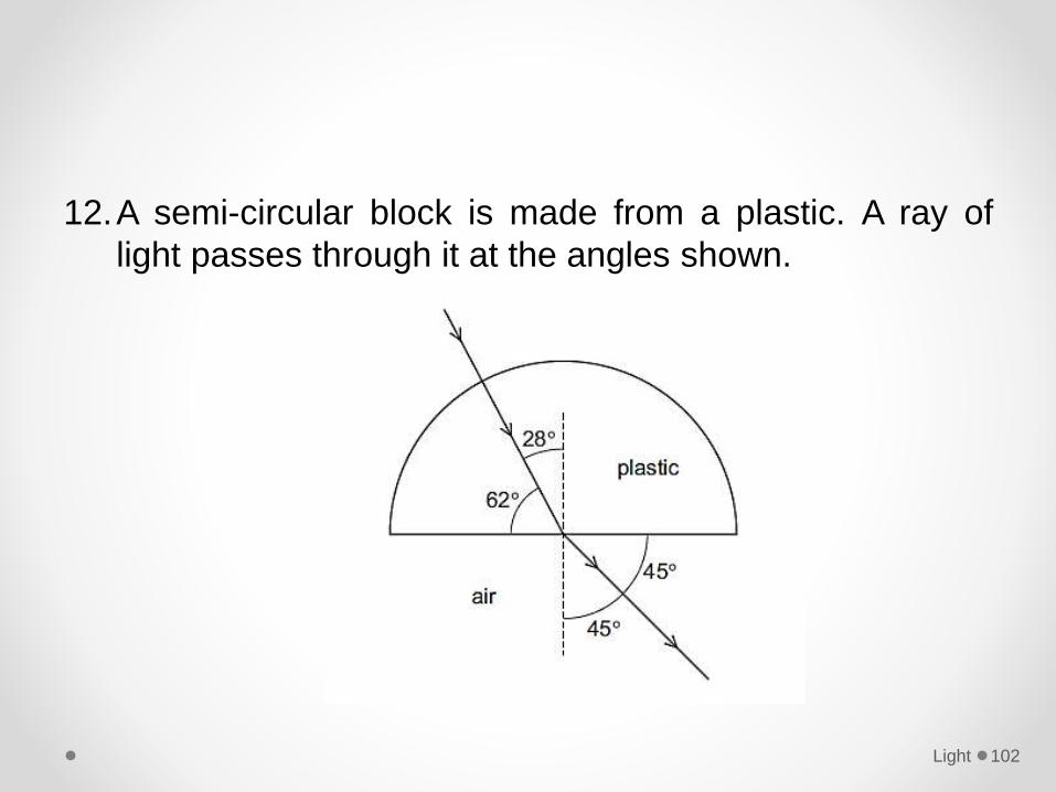
12.A semi-circular block is made from a plastic. A ray of
light passes through it at the angles shown.
Light 102
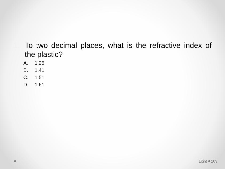
1. To two decimal places, what is the refractive index of
the plastic?A. 1.25
B. 1.41
C. 1.51
D. 1.61
Light 103
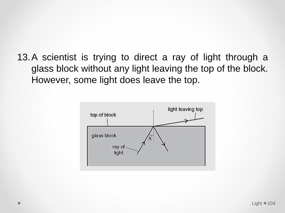
13.A scientist is trying to direct a ray of light through a
glass block without any light leaving the top of the block.
However, some light does leave the top.
Light 104
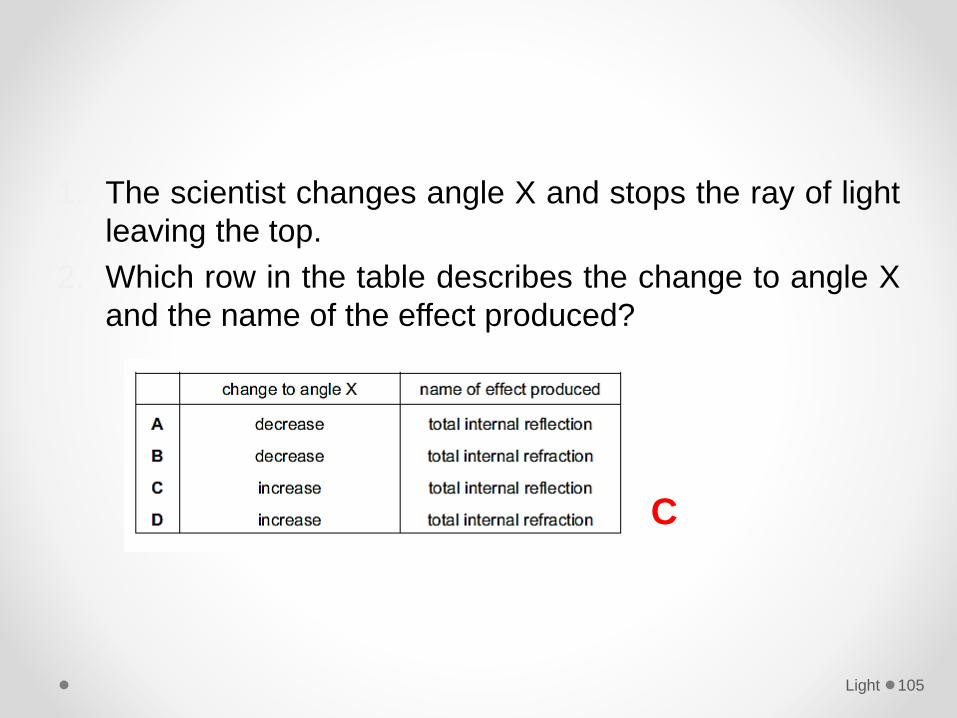
1. The scientist changes angle X and stops the ray of light
leaving the top.
2. Which row in the table describes the change to angle X
and the name of the effect produced?
Light 105
C
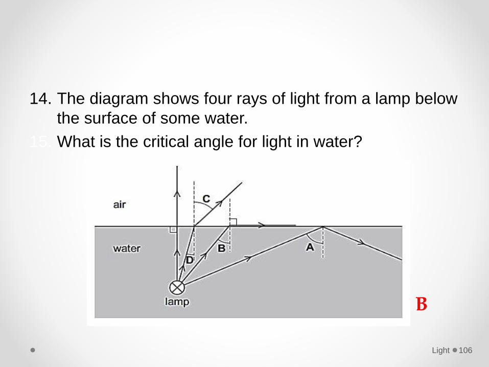
14. The diagram shows four rays of light from a lamp below
the surface of some water.
15. What is the critical angle for light in water?
Light 106
B
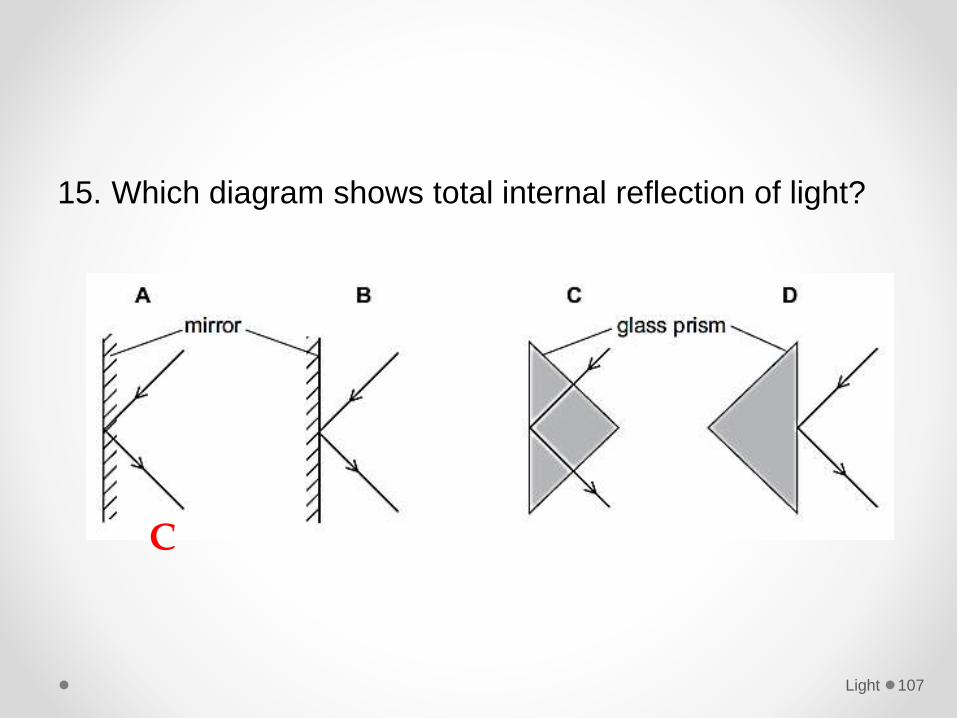
15. Which diagram shows total internal reflection of light?
Light 107
C
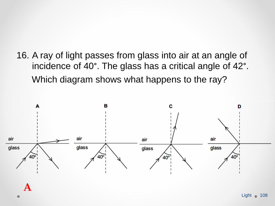
16. A ray of light passes from glass into air at an angle of incidence of 40°. The glass has a critical angle of 42°.
Which diagram shows what happens to the ray?
Light 108
A
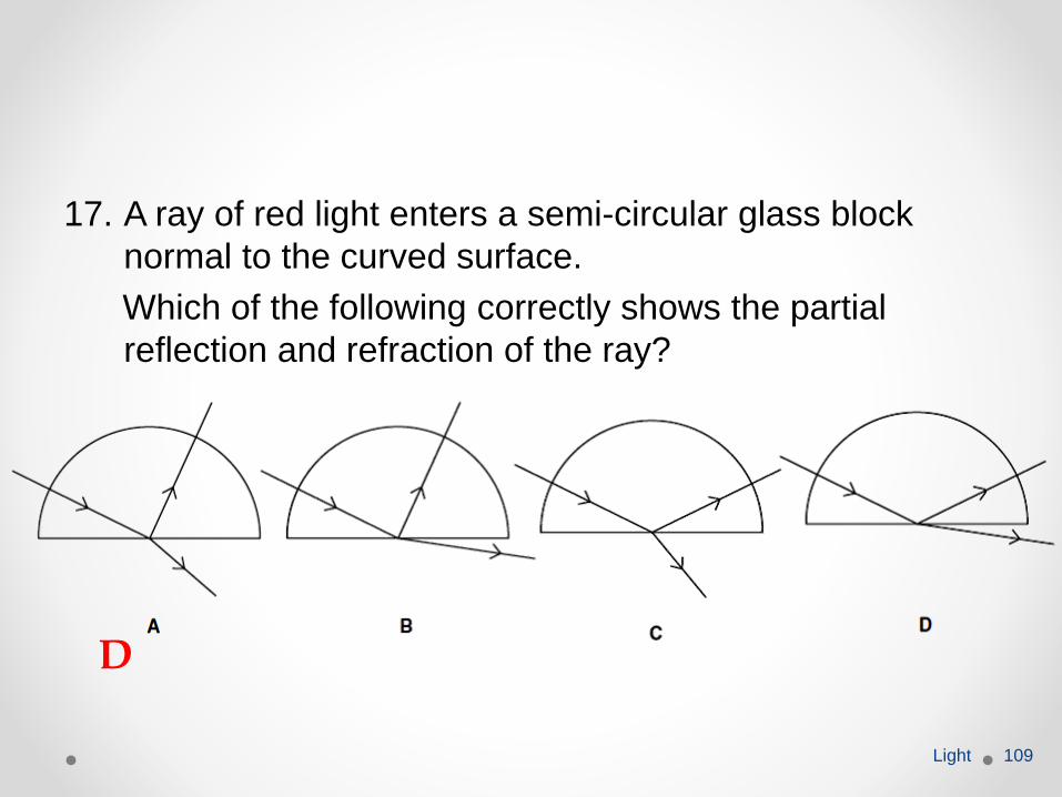
17. A ray of red light enters a semi-circular glass block
normal to the curved surface.
Which of the following correctly shows the partial
reflection and refraction of the ray?
Light 109
D
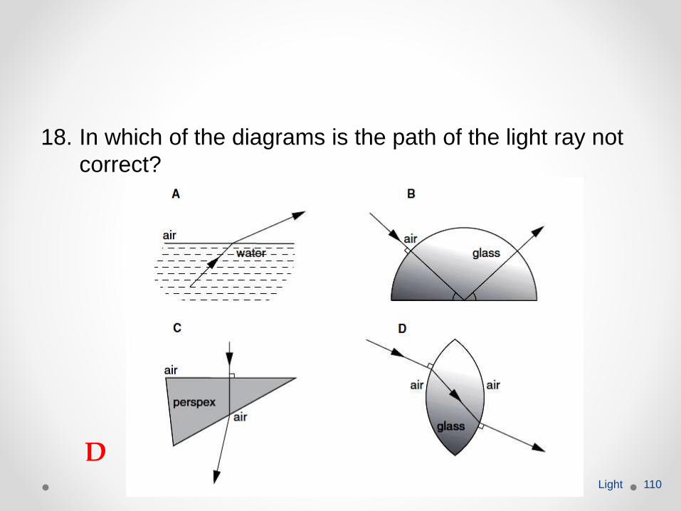
18. In which of the diagrams is the path of the light ray not
correct?
Light 110
D
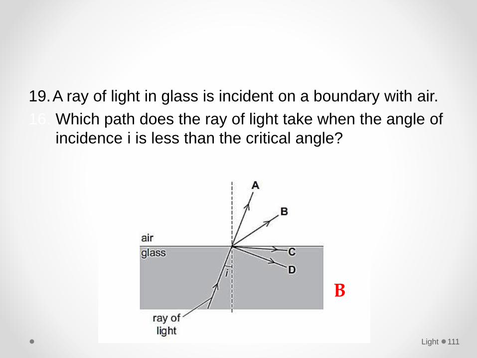
19.A ray of light in glass is incident on a boundary with air.
16. Which path does the ray of light take when the angle of
incidence i is less than the critical angle?
Light 111
B
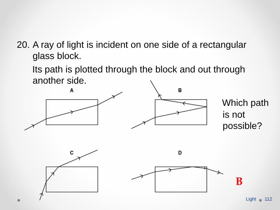
20. A ray of light is incident on one side of a rectangular
glass block.
Its path is plotted through the block and out through
another side.
Light 112
Which path
is not
possible?
B
Thin converging and diverging lenses
Describe the action of thin lenses (both converging
and diverging) on a beam of light.
Light 113
Thin Lenses• Lenses are the most important practical application of
refraction.
• The human eye, spectacles, cameras, telescopes and
microscopes are all contain lenses.
• Most lenses are made from glass of clear plastic.
• In term of structure and function, we can classified
lenses into two categories; converging lenses and
diverging lenses.
Light 114
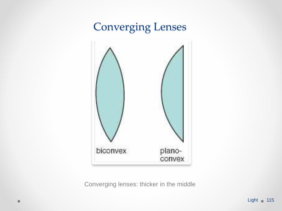
Converging Lenses
Converging lenses: thicker in the middle
Light 115
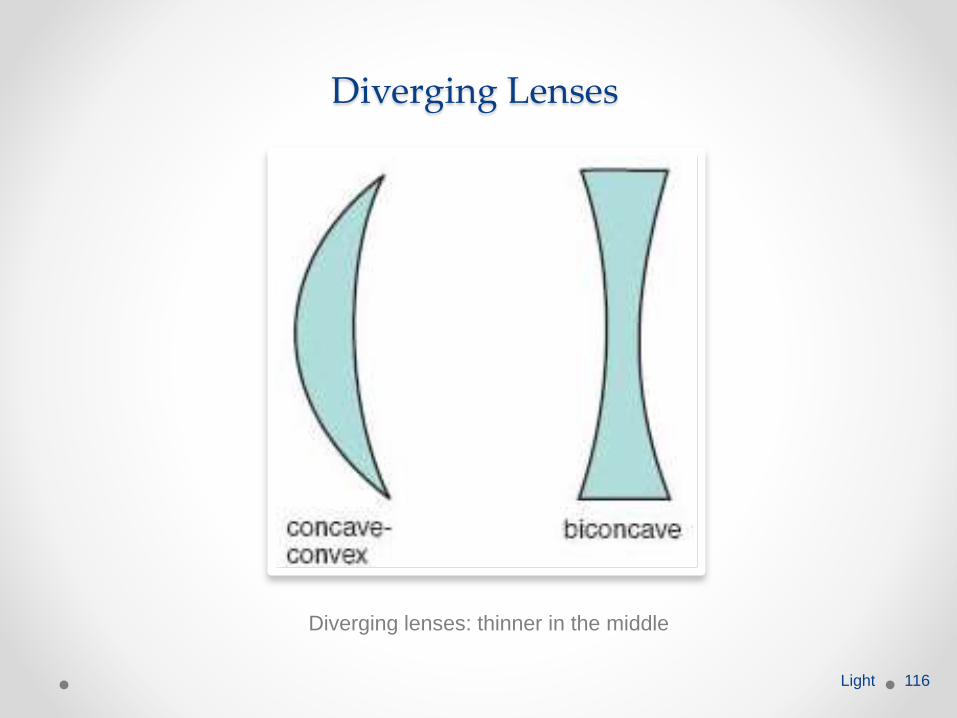
Diverging Lenses
Diverging lenses: thinner in the middle
Light 116
How Do They Work?• We can illustrate the action of a lens by drawing it as a
series of prisms.
• Each ray is refracted towards the normal as it passes
into the glass and away from the normal as it leaves it.
• A converging lens converges (brings together) rays of
light passing through it while a diverging lens diverges
(spreads out) rays of light passing through it.
Light 117
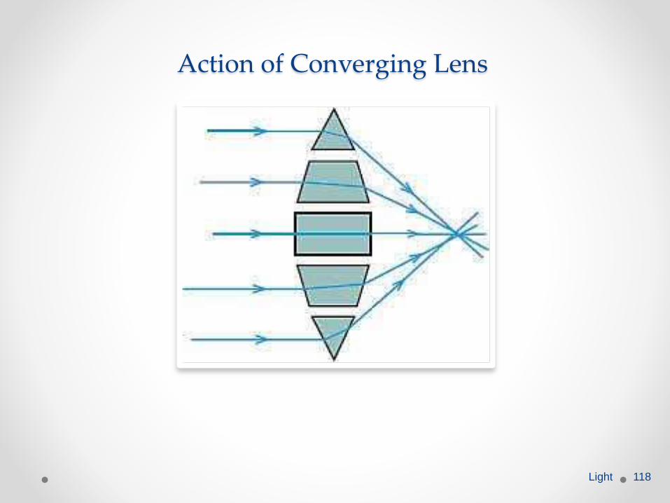
Action of Converging Lens
Light 118
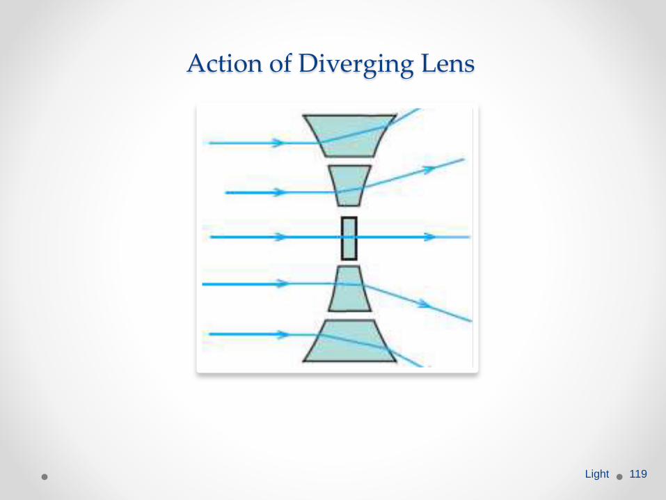
Action of Diverging Lens
Light 119
Thin converging and diverging lenses
Define the term focal length.
Light 120
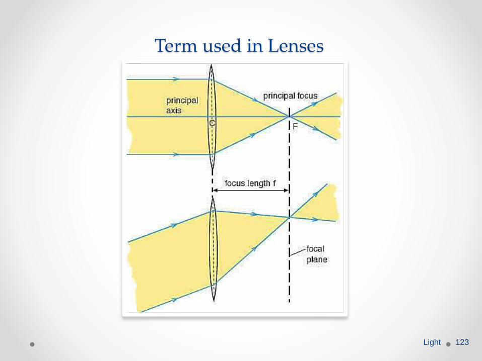
Term Used in Lenses• The principal axis of a lens is a line passing through the
optical centre, C, of the lens perpendicular to the plane
of the lens.
• The optical centre, C, of a lens is the point midway
between the lens surface on its principal axis. Rays
passing through the optical centre are not deviated.
• The principal focus, F of a thin converging lens is the
point on the principal axis, to which an incident beam
parallel to the principal axis is made to converge.
Light 121
• The focal length, f, of a lens is the distance between its
optical centre and principal focus.
• The focal plane of a lens is the vertical plane which
passes through the principal focus and perpendicular to
the principal axis.
Light 122
Term used in Lenses
Light 123
Thin converging and diverging lenses
Draw ray diagrams to illustrate the formation of real
and virtual images of an object by a lens.
Light 124
Thin converging and diverging lenses
Describe the use of a single lens as a magnifying glass and in a camera, projector and photographic enlarger and draw ray diagrams to show how each forms an image.
Light 125
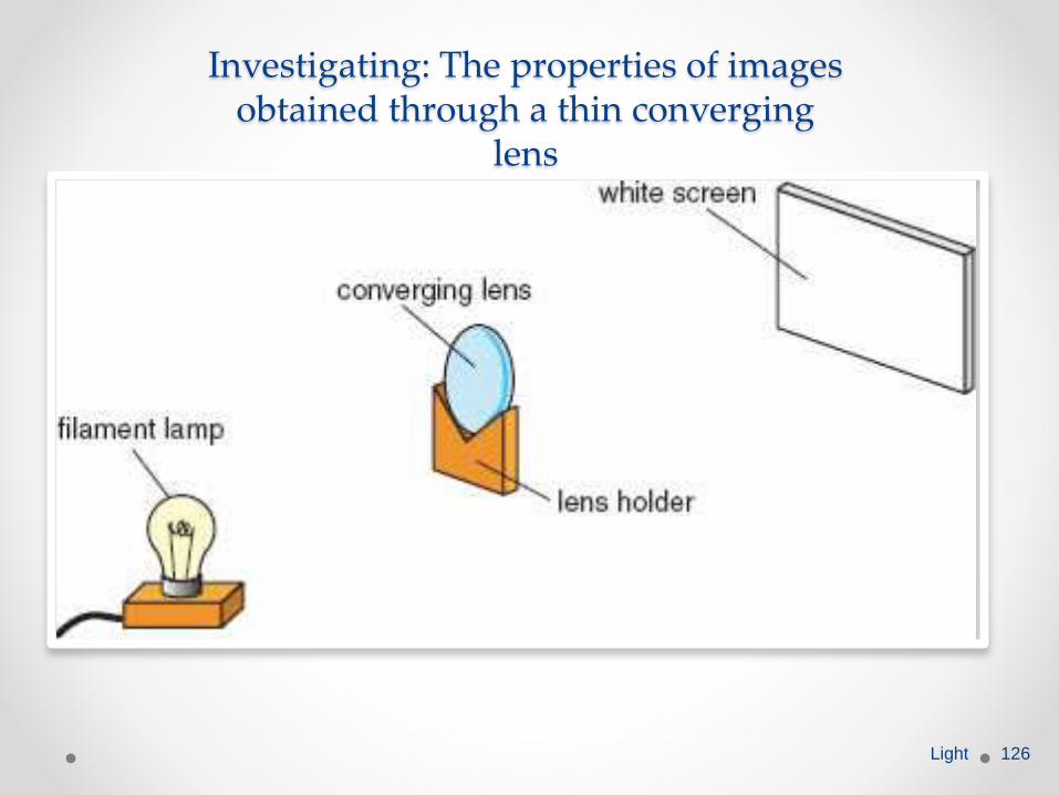
Investigating: The properties of images obtained through a thin converging
lens
Light 126
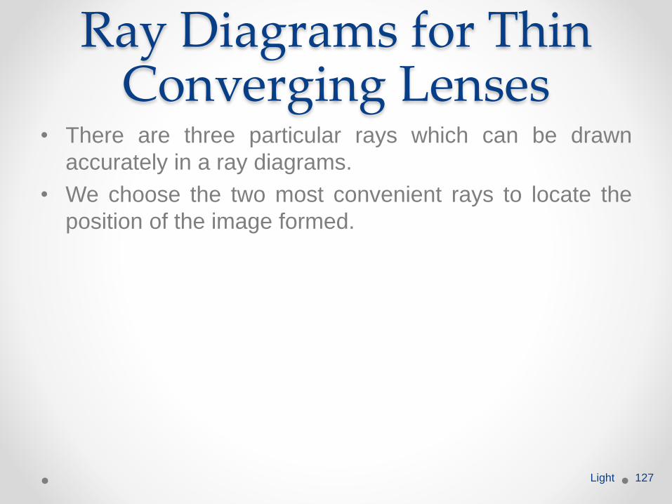
Ray Diagrams for Thin Converging Lenses
• There are three particular rays which can be drawn
accurately in a ray diagrams.
• We choose the two most convenient rays to locate the
position of the image formed.
Light 127
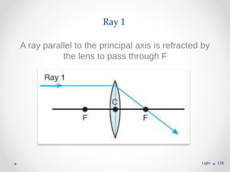
Ray 1
A ray parallel to the principal axis is refracted by
the lens to pass through F
Light 128
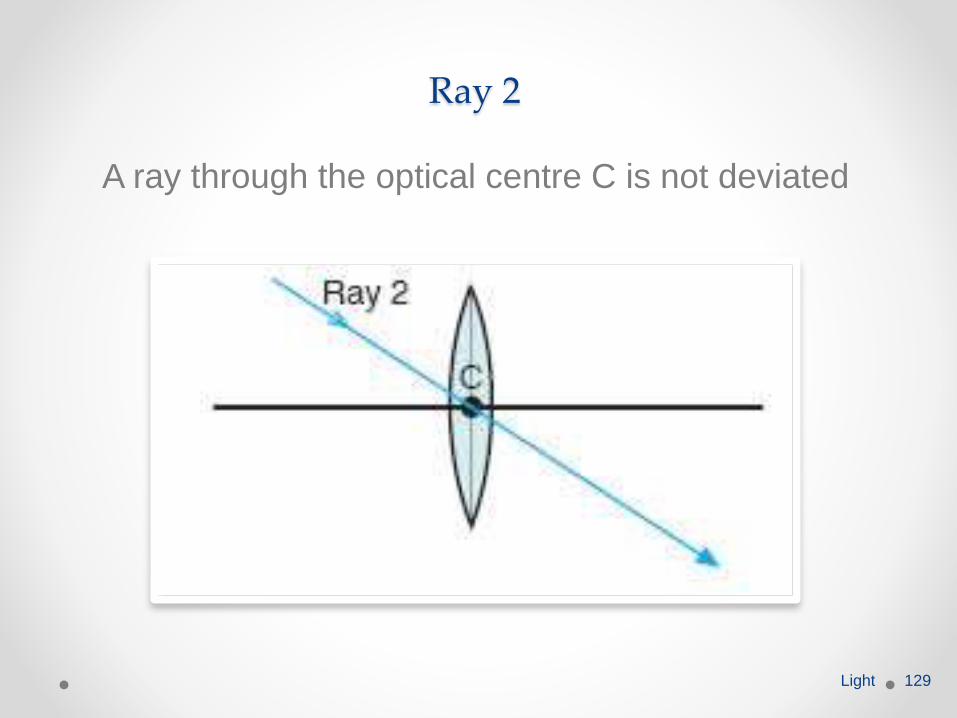
Ray 2
A ray through the optical centre C is not deviated
Light 129
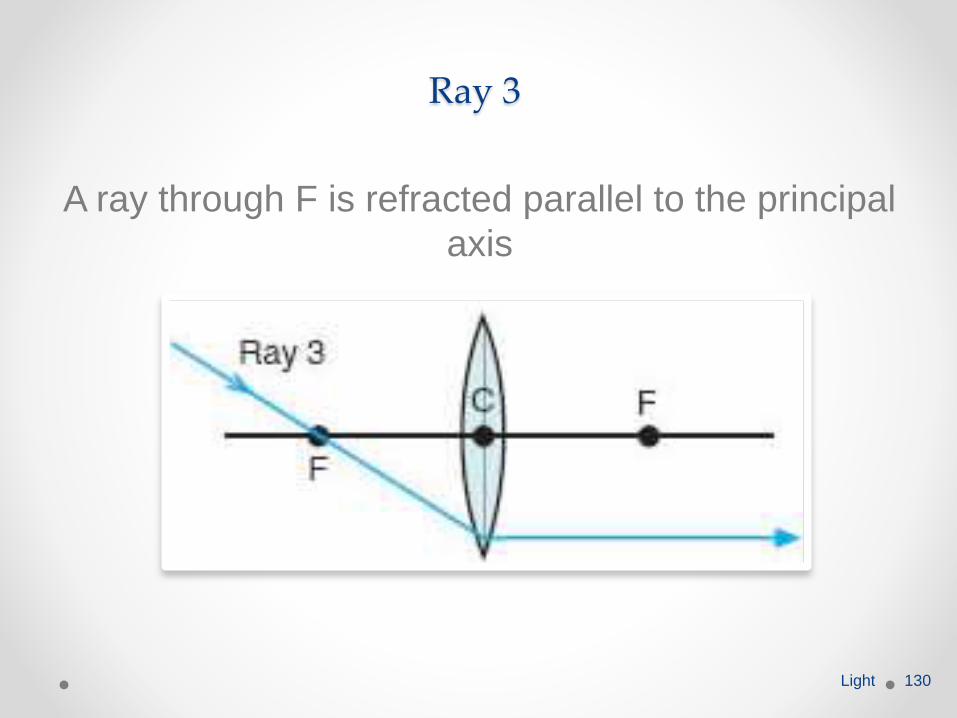
Ray 3
A ray through F is refracted parallel to the principal
axis
Light 130
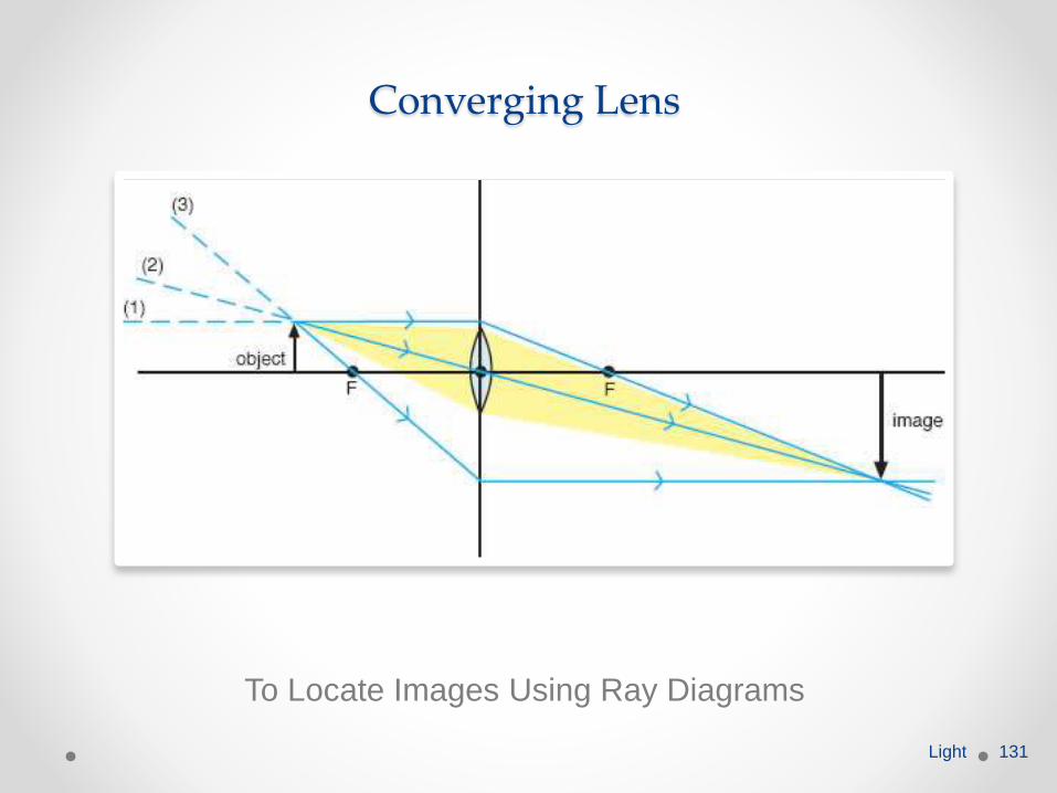
Converging Lens
To Locate Images Using Ray Diagrams
Light 131
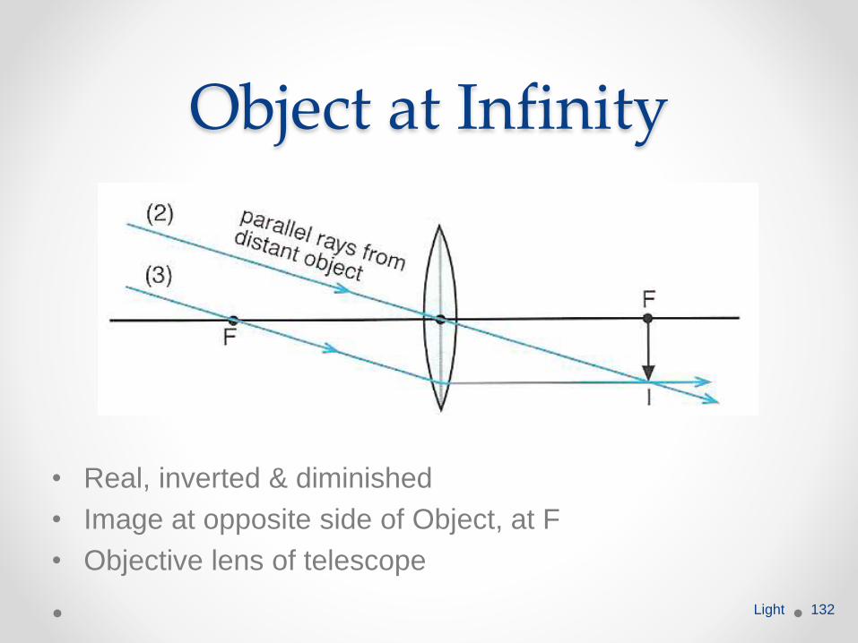
Object at Infinity
• Real, inverted & diminished
• Image at opposite side of Object, at F
• Objective lens of telescope
Light 132
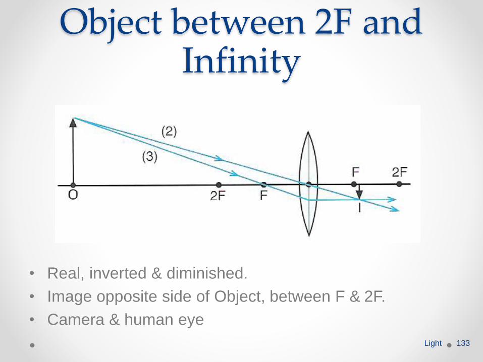
Object between 2F and Infinity
• Real, inverted & diminished.
• Image opposite side of Object, between F & 2F.
• Camera & human eye
Light 133
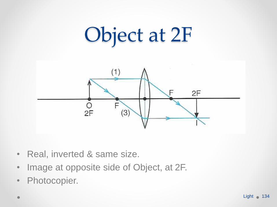
Object at 2F
• Real, inverted & same size.
• Image at opposite side of Object, at 2F.
• Photocopier.
Light 134

Object between F and 2F
• Real, inverted & magnified.
• Image at opposite side of Object, between 2F & infinity.
• Projector & objective lens of microscope.
Light 135
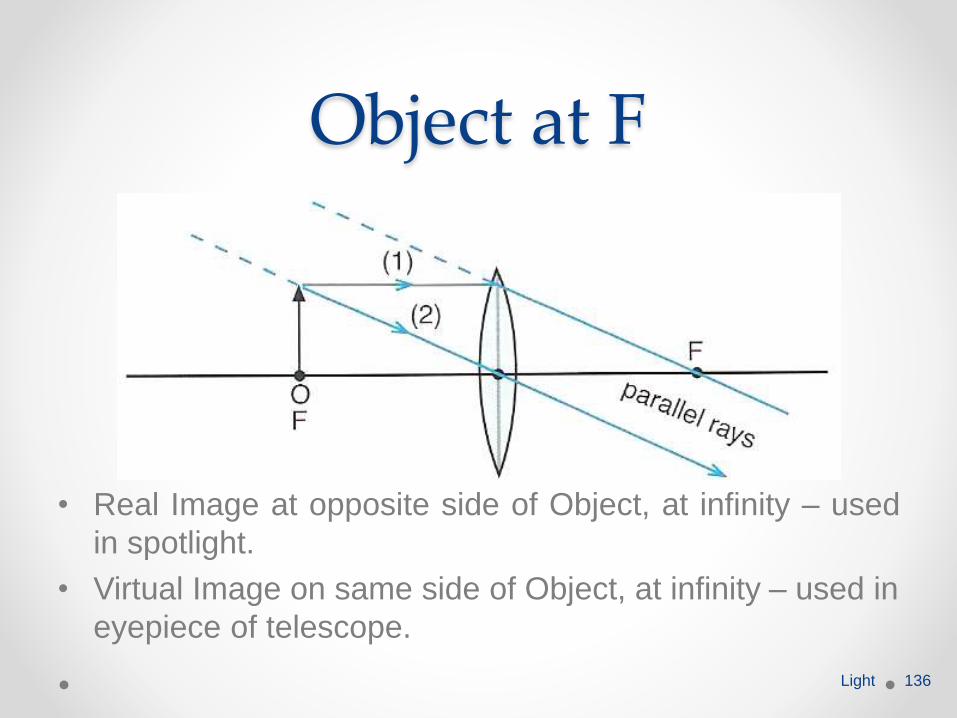
Object at F
• Real Image at opposite side of Object, at infinity – used
in spotlight.
• Virtual Image on same side of Object, at infinity – used in
eyepiece of telescope.
Light 136
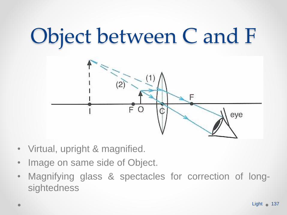
Object between C and F
• Virtual, upright & magnified.
• Image on same side of Object.
• Magnifying glass & spectacles for correction of long-
sightedness
Light 137
Thin converging and diverging lenses
Define the term linear magnification and *draw scale diagrams to determine the focal length needed for particular values of magnification (converging lens only).
Light 138
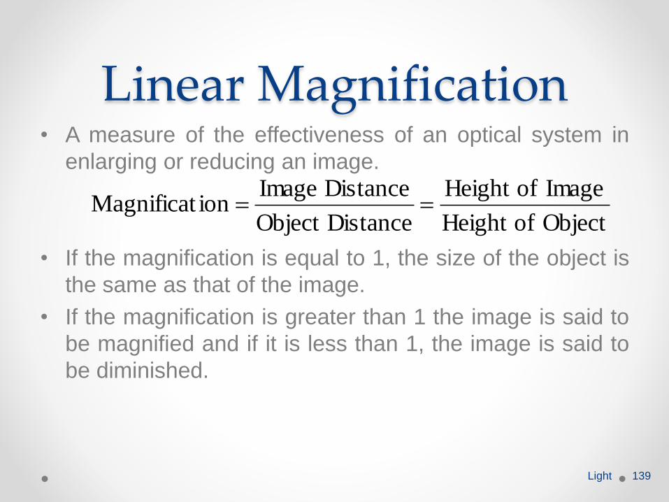
Linear Magnification• A measure of the effectiveness of an optical system in
enlarging or reducing an image.
• If the magnification is equal to 1, the size of the object is
the same as that of the image.
• If the magnification is greater than 1 the image is said to
be magnified and if it is less than 1, the image is said to
be diminished.
Light 139
Object ofHeight
Image ofHeight
DistanceObject
Distance Image ion Magnificat
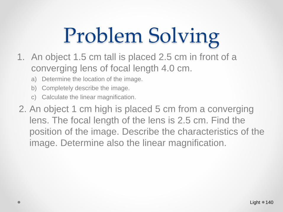
Problem Solving1. An object 1.5 cm tall is placed 2.5 cm in front of a
converging lens of focal length 4.0 cm. a) Determine the location of the image.
b) Completely describe the image.
c) Calculate the linear magnification.
2. An object 1 cm high is placed 5 cm from a converging
lens. The focal length of the lens is 2.5 cm. Find the
position of the image. Describe the characteristics of the
image. Determine also the linear magnification.
Light 140
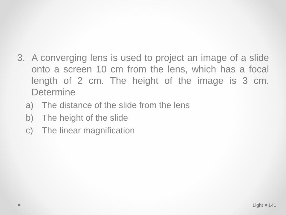
3. A converging lens is used to project an image of a slide
onto a screen 10 cm from the lens, which has a focal
length of 2 cm. The height of the image is 3 cm.
Determine
a) The distance of the slide from the lens
b) The height of the slide
c) The linear magnification
Light 141
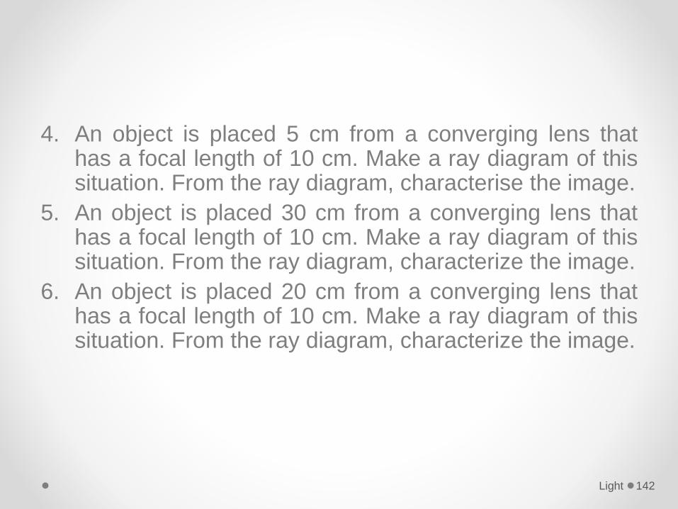
4. An object is placed 5 cm from a converging lens thathas a focal length of 10 cm. Make a ray diagram of thissituation. From the ray diagram, characterise the image.
5. An object is placed 30 cm from a converging lens thathas a focal length of 10 cm. Make a ray diagram of thissituation. From the ray diagram, characterize the image.
6. An object is placed 20 cm from a converging lens thathas a focal length of 10 cm. Make a ray diagram of thissituation. From the ray diagram, characterize the image.
Light 142
Thin converging and diverging lenses
Draw ray diagrams to show the formation of images in the normal eye, a short-sighted eye and a long-sighted eye.
Light 143
Thin converging and diverging lenses
Describe the correction of short-sight and long-sight.
Light 144
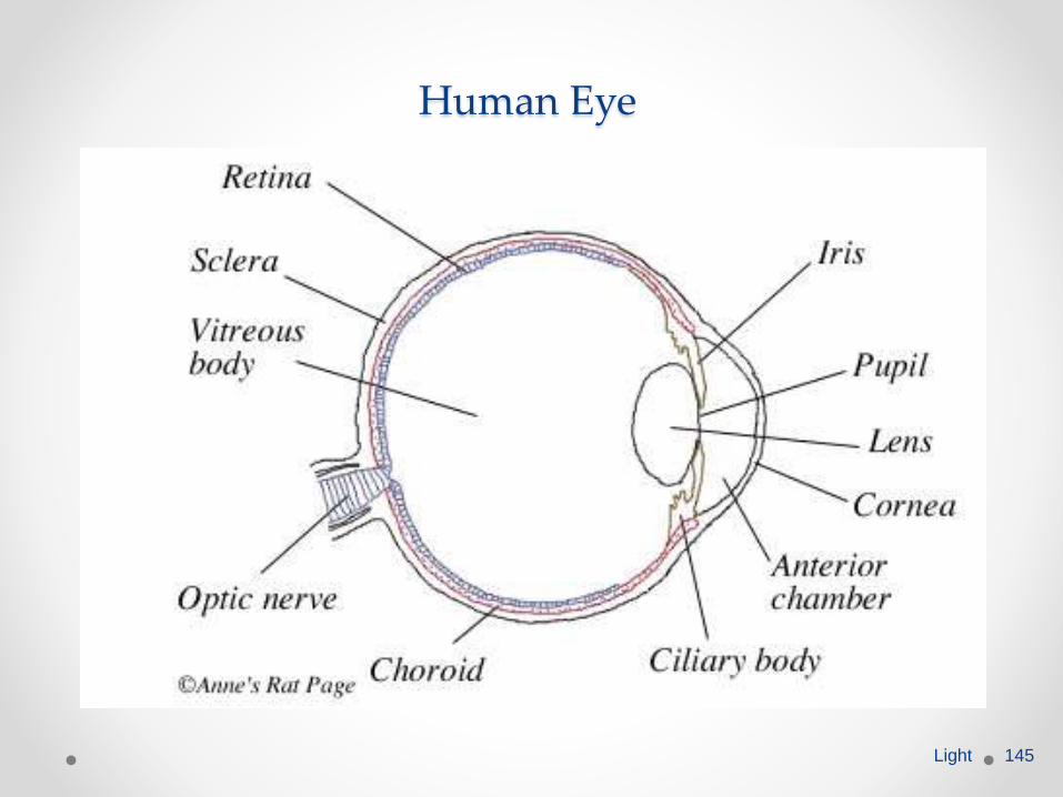
Human Eye
Light 145
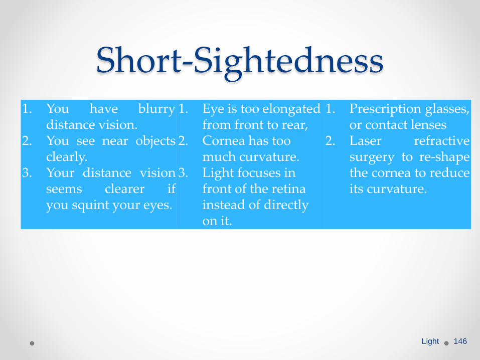
Short-Sightedness1. You have blurry
distance vision.2. You see near objects
clearly.3. Your distance vision
seems clearer ifyou squint your eyes.
1. Eye is too elongated from front to rear,
2. Cornea has too much curvature.
3. Light focuses in front of the retina instead of directly on it.
1. Prescription glasses,or contact lenses
2. Laser refractivesurgery to re-shapethe cornea to reduceits curvature.
Light 146
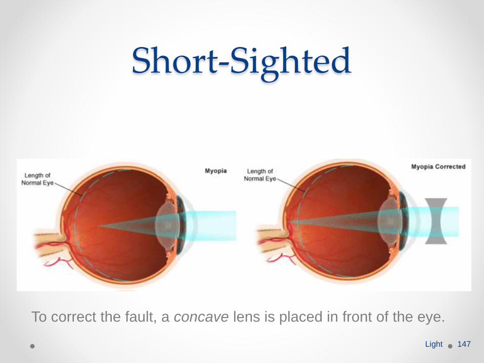
Short-Sighted
To correct the fault, a concave lens is placed in front of the eye.
Light 147
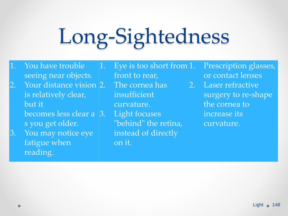
Long-Sightedness1. You have trouble
seeing near objects.2. Your distance vision
is relatively clear, but itbecomes less clear as you get older.
3. You may notice eye fatigue when reading.
1. Eye is too short from front to rear,
2. The cornea has insufficient curvature.
3. Light focuses "behind" the retina, instead of directly on it.
1. Prescription glasses, or contact lenses
2. Laser refractive surgery to re-shape the cornea to increase its curvature.
Light 148
Long-Sighted
To correct the fault, a convex lens is placed in front of the eye.Light 149
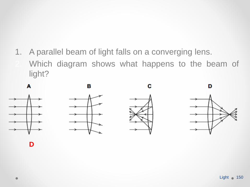
1. A parallel beam of light falls on a converging lens.
2. Which diagram shows what happens to the beam of
light?
Light 150
D
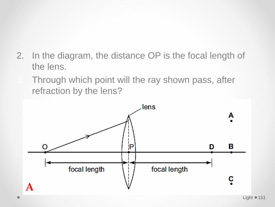
2. In the diagram, the distance OP is the focal length of
the lens.
3. Through which point will the ray shown pass, after
refraction by the lens?
Light 151
A
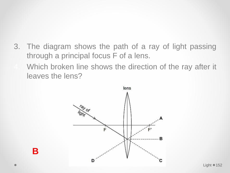
3. The diagram shows the path of a ray of light passing
through a principal focus F of a lens.
4. Which broken line shows the direction of the ray after it
leaves the lens?
Light 152
B
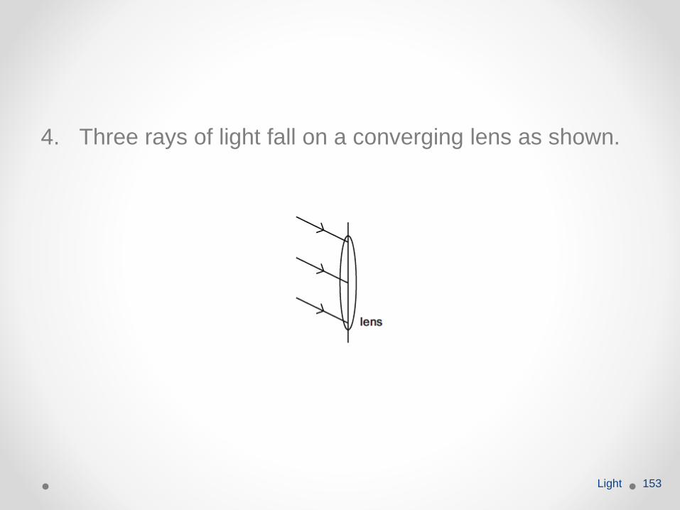
4. Three rays of light fall on a converging lens as shown.
Light 153
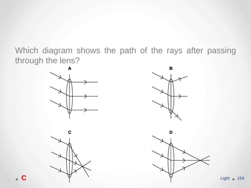
Which diagram shows the path of the rays after passing
through the lens?
Light 154C
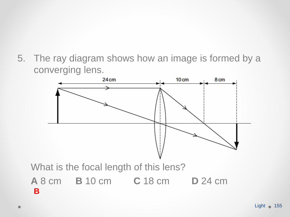
5. The ray diagram shows how an image is formed by a
converging lens.
What is the focal length of this lens?
A 8 cm B 10 cm C 18 cm D 24 cm
Light 155
B
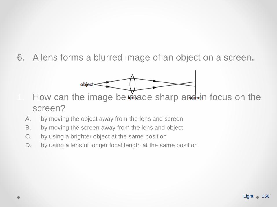
6. A lens forms a blurred image of an object on a screen.
1. How can the image be made sharp and in focus on the
screen?A. by moving the object away from the lens and screen
B. by moving the screen away from the lens and object
C. by using a brighter object at the same position
D. by using a lens of longer focal length at the same position
Light 156
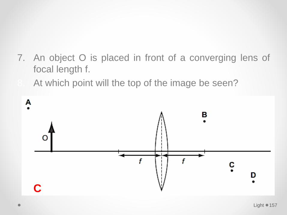
7. An object O is placed in front of a converging lens of
focal length f.
8. At which point will the top of the image be seen?
Light 157
C
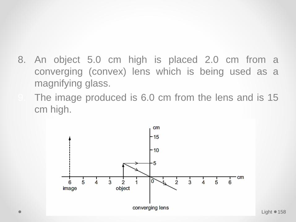
8. An object 5.0 cm high is placed 2.0 cm from a
converging (convex) lens which is being used as a
magnifying glass.
9. The image produced is 6.0 cm from the lens and is 15
cm high.
Light 158
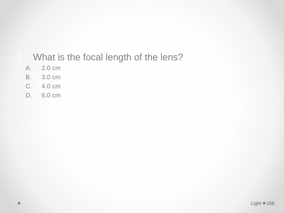
1. What is the focal length of the lens?A. 2.0 cm
B. 3.0 cm
C. 4.0 cm
D. 6.0 cm
Light 159
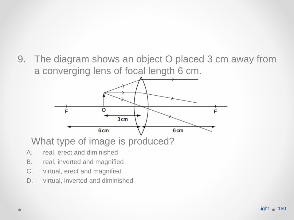
9. The diagram shows an object O placed 3 cm away from
a converging lens of focal length 6 cm.
What type of image is produced?A. real, erect and diminished
B. real, inverted and magnified
C. virtual, erect and magnified
D. virtual, inverted and diminished
Light 160
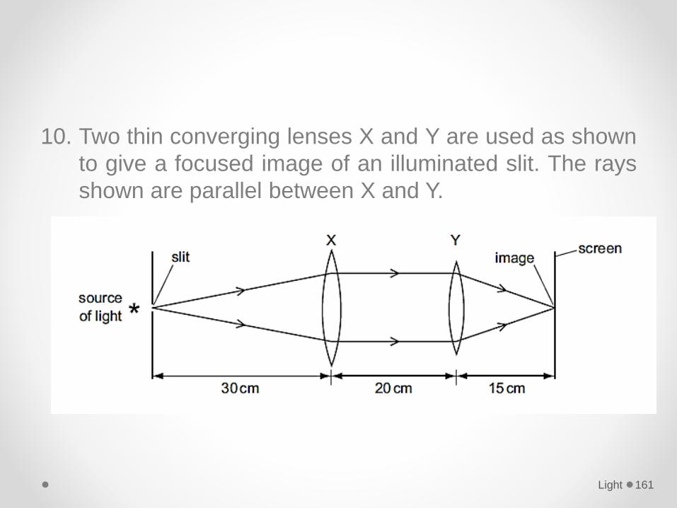
10. Two thin converging lenses X and Y are used as shown
to give a focused image of an illuminated slit. The rays
shown are parallel between X and Y.
Light 161
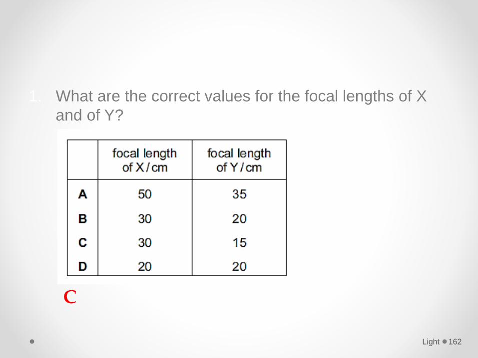
1. What are the correct values for the focal lengths of X
and of Y?
Light 162
C
11. An object is placed in front of a diverging lens as shown
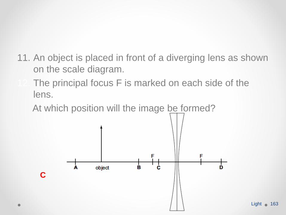
on the scale diagram.
12. The principal focus F is marked on each side of the
lens.
At which position will the image be formed?
Light 163
C
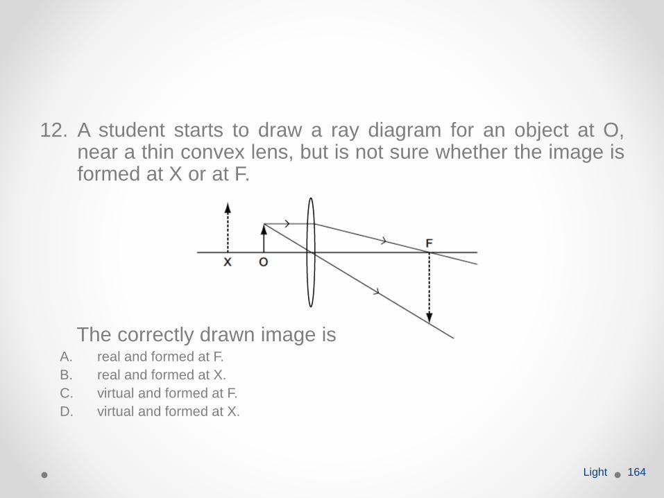
12. A student starts to draw a ray diagram for an object at O,near a thin convex lens, but is not sure whether the image isformed at X or at F.
The correctly drawn image isA. real and formed at F.
B. real and formed at X.
C. virtual and formed at F.
D. virtual and formed at X.
Light 164
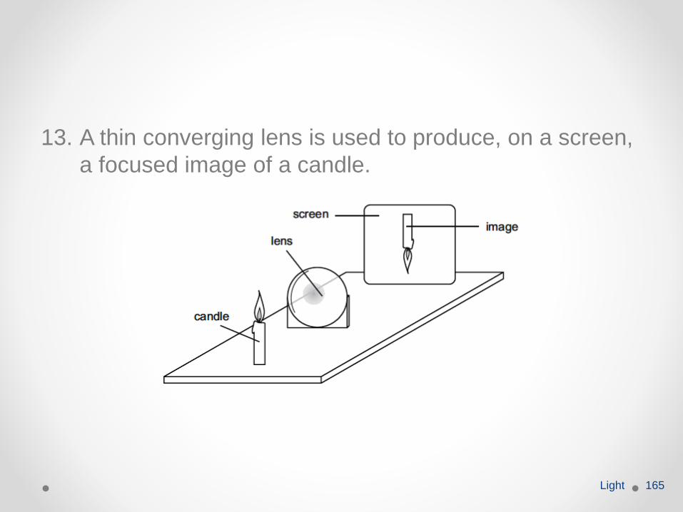
13. A thin converging lens is used to produce, on a screen,
a focused image of a candle.
Light 165
1. The screen and the lens are moved back and forth and
various focused images are produced on the screen.
2. Which statement is always true?A. The image is at the principal focus (focal point) of the lens.
B. The image is bigger than the object.
C. The image is closer to the lens than the object is.
D. The image is inverted.
Light 166
14. What is true for real images formed by a converging
lens?A. They are inverted.
B. They are on the same side of the lens as the object.
C. They can never be shown on a screen.
D. They cannot be seen by the human eye.
Light 167
15. The human eye has a converging lens system that
produces an image at the back of the eye.
16. An eye views a distant object. What type of image is
produced?A. real, erect, same size
B. real, inverted, diminished
C. virtual, erect, diminished
D. virtual, inverted, magnified
Light 168
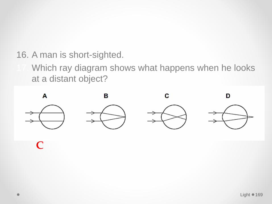
16. A man is short-sighted.
17. Which ray diagram shows what happens when he looks
at a distant object?
Light 169
C
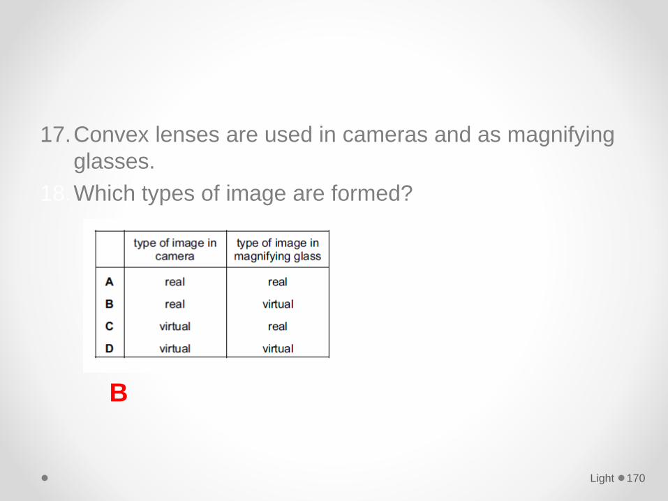
17.Convex lenses are used in cameras and as magnifying
glasses.
18.Which types of image are formed?
Light 170
B
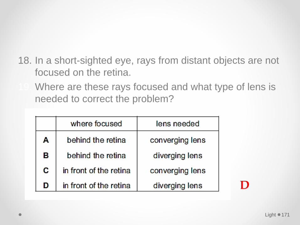
18. In a short-sighted eye, rays from distant objects are not
focused on the retina.
19. Where are these rays focused and what type of lens is
needed to correct the problem?
Light 171
D
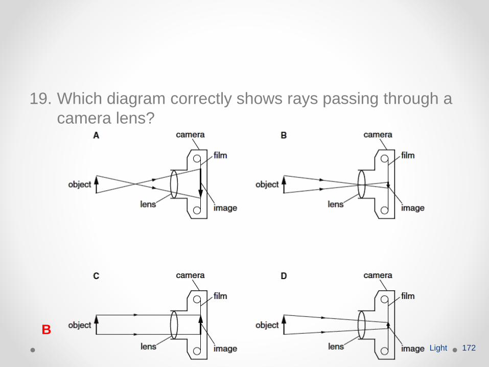
19. Which diagram correctly shows rays passing through a
camera lens?
Light 172
B