Liftparker Mobil LPM
25
Liftparker Mobil LPM Assembly instruction Stand 04/2008 A Company of the NUSSBAUM Group S M T Sheet Metal Technologies GmbH \\ Hertzstrasse 6 \\ D 77694 Kehl – Sundheim Tel.: +49 (0) 7851 / 741-0 \\ Fax: +49 (0) 7851 / 741 - 50 E-Mail.: [email protected] \\ http://www.sm-t.de
Transcript of Liftparker Mobil LPM
Liftparker Mobil LPM
Assembly instruction Stand 04/2008
A Company of the NUSSBAUM Group S M T Sheet Metal Technologies GmbH \\ Hertzstrasse 6 \\ D 77694 Kehl – Sundheim
Tel.: +49 (0) 7851 / 741-0 \\ Fax: +49 (0) 7851 / 741 - 50
E-Mail.: [email protected] \\ http://www.sm-t.de

Assembly instruction
- 2 -
Content:
1. Assembly and Starting up........................................................3
1.1 Assembly guidelines................................................................3
1.2 Starting up................................................................................3
2 Recommended tools.................................................................4
3 Dimensions of the Car Parking Systems..................................5
4 Assembly procedure of the Car Parking Systems....................7
5 Circuit diagram...................................................................... 23
6 Hydraulic drawing..................................................................24
7 Hydraulic part lists..................................................................25
Assembly instruction
- 3 -
1. Assembly and Starting up
1.1 Assembly guidelines
• The assembly of the parking systems occurs through trained fitters of the manufacturer
or the appointed retailer.
• Before the start of assembly a corresponding setting tier is to be made out with a floor
loading imposed by equipment by 60 N/ cm² for single systems and 120 N / cm² for
multiple systems, and the foundations in the open air or in rooms in which winter scent
or frost are to be reckoned on, are to be set up frost-deep.
• For the electric connection is constructional 3 PE ~/N +, 400, to provide 50Hz.
• The incoming line is to be protected constructionally to the locally valid guidelines.
• To the protection of the electrical cords all cable lead-throughs are to be equipped with
cable support sleeves or flexible epoxy tubes.
• The junction is in the elektrobox of the operating hydraulic unit.
1.2 Starting up
Before the initiation the unique safety inspection must be carried out (To employ
form "Unique safety inspection")
The assembly of the system occurs through one experts (factory trained fitter) this carries
out the safety inspection. The assembly occurs through the operator a technical expert is to
be instructed with the safety inspection. The faultless function of the system confirms to
the expert on the list-record and the form for the unique safety inspection and unlocks the
plant for the use.
After the initiation the list record must filled and send to the manufacturer.

Assembly instruction
- 4 -
2 Recommended Tools
- we recommend at least 2 fitters and 1 helper for the assembly - 1 fork-lift with a length of stroke of min 5 meters and a fork prolongation of at
least 2,5 meters
- lifting volume, approx. 1 meter (high-version)
- 2 pieces strong clamps
- Tool box with fork ring key, allen wrench, knarren- key with commitments,
hammer and, screwdriver, etc.
- lifting-iron
- centering spike
- dynamometric key 60-320 Nm.

Assembly instruction
- 5 -
3 Dimensions of the Car Parking Systems:
column-
outer
Platform-
outer platform-
inner foot flange
outer column
outer column
outer/outer column
height
platform
bottom
edge
Column
Middle Type
A B C D E F G H I
2578 2230 2140 2598 2578 2438 3200 1765 2438 Low.
2738 2390 2300 2758 2738 2598 3200 1765 2598 Low.
2578 2230 2140 2598 2578 2438 3538 2100 2438 High
2738 2390 2300 2758 2738 2598 3538 2100 2598 High
2578 2230 2140 2598 2578 2438 4285 2800 2438 Van
2738 2390 2300 2758 2738 2598 4285 2800 2598 Van
Top view
Front view for Multiple Systems
Imoprtant:
The maximum allowed ground slope in cross direction system is 1
cm/ m. The maximum allowed ground slope in longitudinal
direction system is 1,5 cm/ m. The maximum allowed unevenness is
in 1 cm the field of the setting tier.
70 cm mini Hydraulic power unit 250 700 mm mini
Electrical switch cabinet

Assembly instruction
- 6 -
The setting tier must withstand a load of 60 N/cm² for the columns
of single systeem, and 120 N./cm² for the columns of multiple
systems.
The distance to the rear sturgeon rim must least be 70cm

Assembly instruction
- 7 -
4 Assembly procedure of the Parking System: The maximum allowed ground slope in cross direction Parker is 1 cm/ m.
Putting the platform on squared timbers (approx. 15 cm high).
Caution: Putting the platform on the precise position.
1. Placing the columns next to the platform, shown as on the picture.
2. Introducing the cord protective tube in the left column behind.
3. Introducing the sledge units in the columns.
Caution: There are a left one and a right sledge.
Introducing a sledge at Mehrfachparker on both pages of the central column.
Important: Control the situation of the sledges to the columns
Attention: Auf Scher und Quetschstellen achten beim Einführen
des Schlittens in die Säule

Assembly instruction
- 8 -
If the sledge is in the lower field of the column, and/or if the suspension is run over
to the concatenation at the column, mounting the deflection sheave then for the
concatenation and safeguarding the bolt with a split pin.
The flattened place of the alliance at the bolt must be next to the Flach set onto the
strap. (Anti-twist stop)
4. Attaching the column and setting up the column. Paying attention to perfect, tested
lifting-materials ! (Emphasis of the column : approx. 500 Kg )

Assembly instruction
- 9 -
5. Leading the column onto the platform. Lifting the column which punctures true
from platform and sledge suitingly easily. and that upper screw line of the sledge
with the platform screw together, 4 screws M 16 x 40 with 2 panes and safety
mother. The safety mother to come after outside. ( Suit momentum: 220 Nm)
Installing cylinder in the column.
The coil into the lower inner one
(the sledge seem likely) mount
set up. The pipe connection
showing after behind ensure. The
piston-rod being embedded
above into the boring of the shift
sledge and safeguarding M6x16
with a setscrew.

Assembly instruction
- 10 -
6. To introduce the foot console behind and to screw together the foot console, with
per 2 lentil flange screws M10 x of 20 panes and mother on every page.
The points 4 to 11 for the other column repeat.
7. M16 x 80 of in each case 2 panes and safety mother screw the foot consoles at the
columns with 6 screws. ( Suit momentum: 220 Nm)
8. At multiple systems the first system set then the further platform onto the place
produces set and the further column set up. ( Course of events of point 1 until 13)
9. Inserting the fuse strip and screwing 2xM10 with the
foot consoles with screws.
Fuse strip

Assembly instruction
- 11 -
10. The rear management channel
and both pages with 2x1 of
mother M8 and screw 2x2 M8
screw together
11. The right angle and the
diagonals check and the front
foot console verduebeln D12
12. Assembly of the electrical lines
- The main-current- connection 400V ~3P/N/PE must be constructional laid.
- The electrical point must be provided with a main lockable power switch in position
of rest.
The connection may be carried out only from one experienced electrician.
- Before the system may be connected to the main net, the management transfer must
be tested at the parking system:
- Exact transfer without train on the cords.
- Clean and dense cable entry into the elektrodoses.
- Cords must not be installed about angular parts.
- The system must be dry and free from oily arrearages in the field of the cable-laying.
2 screws M10 adduct +
2 high-powered anchors M12
Electrical line
Connection on site
Electrical switch cabinet
Hydraulic
power unit
Further systems
Magnet valve

Assembly instruction
- 12 -
13. The system control console onto the left column into a height of approx. 180 to 200
cm with Halfenscrews. M12x40 of pane and mother, screw together.
With the aid of the puller screw the height can be tuned still individually. To loosen
the upper screws here too so far, height desired to the system control console onto
that one stands (Tube stands diagonally after below). Attracting the two puller
screws then until the arm stands firmly. ,dass of the arms do not pay attention to
that at the platform can roam.
Introducing the cord hose up to the branch box.
14. Assembly of the pre-assembled electrical lines.
15. Connecting the cable according to the elektrical drawing.
Assembly instruction
- 13 -
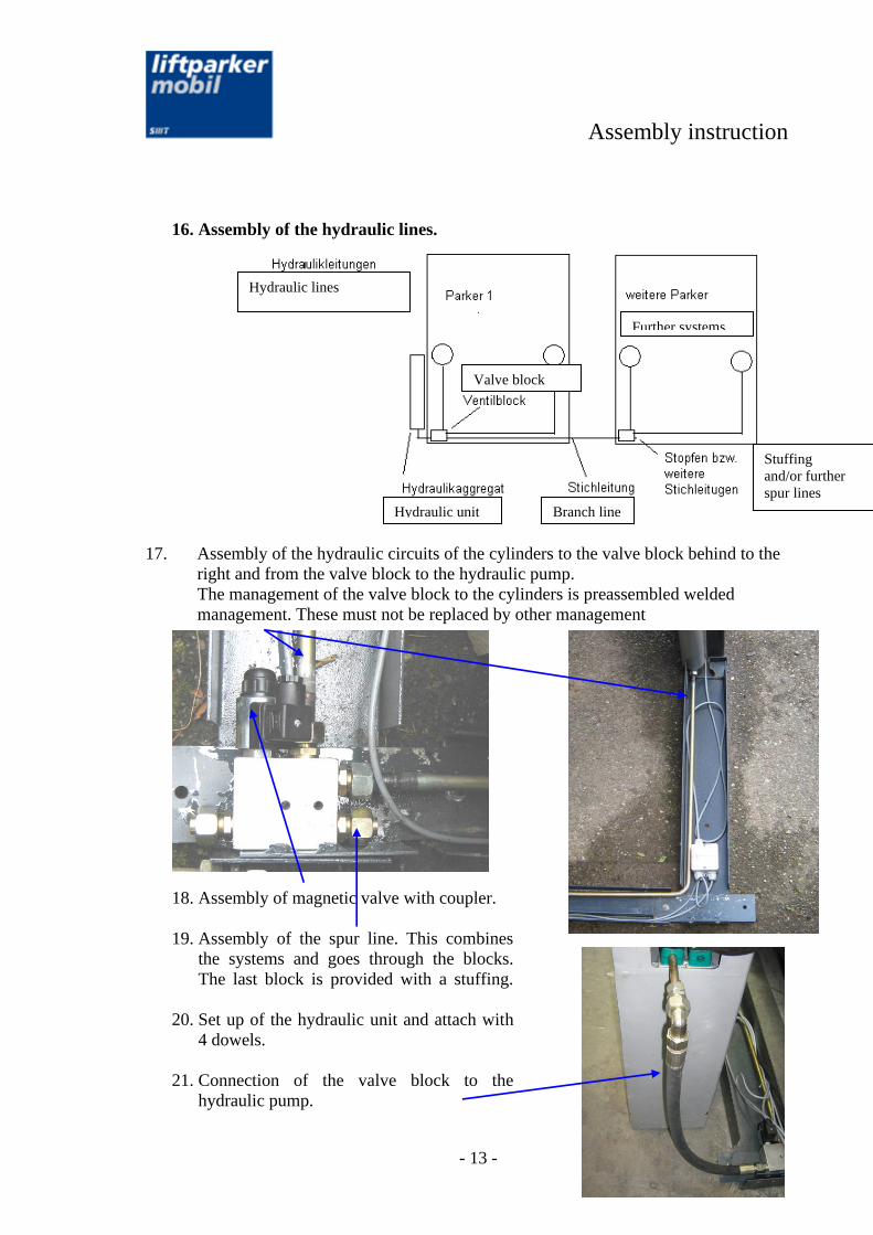
16. Assembly of the hydraulic lines.
17. Assembly of the hydraulic circuits of the cylinders to the valve block behind to the
right and from the valve block to the hydraulic pump.
The management of the valve block to the cylinders is preassembled welded
management. These must not be replaced by other management
18. Assembly of magnetic valve with coupler.
19. Assembly of the spur line. This combines
the systems and goes through the blocks.
The last block is provided with a stuffing.
20. Set up of the hydraulic unit and attach with
4 dowels.
21. Connection of the valve block to the
hydraulic pump.
Hydraulic lines
Further systems
Valve block
Hydraulic unit Branch line
Stuffing
and/or further
spur lines

Assembly instruction
- 14 -
22. To remove air from the cylinder.
Fill the hydraulic unit completely with the required oil amount approx. 70 liters
(Oil model HLP32 )
- The lower chamber of the Hydraulic system becomes about the ventilation
screws 2nd (see picture) at the elevating ram purges. To open the screws
easily and to activate the hydraulic unit through function " lift ". As Soon as
oil are left to close the ventilation screws again.
- Then the upper chamber of the hydraulic system about the ventilation
screws 1st (see picture) at the elevating ram purge. To open the screws
easily and to activate the hydraulic unit through the function " lift ". As soon
as oil are left to close the ventilation screws again.
Attention: Every ventilation screw (see picture ) to open with an allen
wrench separately. (Not to unscrew). As soon as oil is left the screw
again conclude. This course of events must be repeated at all ventilation
screws.
Fig. : Situation of the ventilation screws
1 Ventilation screw for the upper chamber
2 Ventilation screw for the lower chamber
23. To lift the platform on approx. 800 mm height, to mount the concatenation then.

Assembly instruction
- 15 -
24. Introducing the concatenation system.
Attention: The concatenation must not be twisted. The concatenation is in each
case in a tier. If one stands before the parking system, the concatenation is that one
at the right column below is attached, in the front tier is. The concatenation the at
the left column below is attached in the rear tier.
Let the clamping bolts during the introduction of the concatenation completely
open.
Pocketing a concatenation per page.
Attention: The concatenation must not be due to the ground or may come with dirt
into touch.
Left column Right column
Assembly instruction
- 16 -
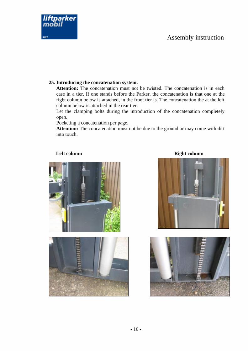
25. Introducing the concatenation system.
Attention: The concatenation must not be twisted. The concatenation is in each
case in a tier. If one stands before the Parker, the concatenation is that one at the
right column below is attached, in the front tier is. The concatenation the at the left
column below is attached in the rear tier.
Let the clamping bolts during the introduction of the concatenation completely
open.
Pocketing a concatenation per page.
Attention: The concatenation must not be due to the ground or may come with dirt
into touch.
Left column Right column

Assembly instruction
- 17 -
Carrying out the concatenation at the page at which the concatenation is firm above in
the column under the deflection sheave and carrying out on the opposite side about the
role and going then after below by the column foot.
26. The concatenation at the column
foot with 1 chain stud and 2 split
pins attach and safeguard the
concatenation at the column foot
with 1 chain stud and 2 split pins
The Concatenation System
would pull in.
Attention: The concatenation spun if both
coils are at the upper assault.
27. The concatenation tightens.
The initial tension of the
concatenation must not be too
strong. These must yield least
approx. 2 cm with easy
Daumendrueck in the middle of
the platform.

Assembly instruction
- 18 -
27. Installing the interlocking system.
- Introducing the wave for the lock.
Attention: under the platform the
actuating lever must be introduced.
- Assembly of the handle with setscrew
M6x12.
- The handles must have the same
bearing to the left and to the right. The
wave must survive at every page in a
least flush way.
- The wave has in each case a small
groove at three places at which the
handles stand. The setscrew must
intervene in this groove.
- Assembly of the handle plate with rear
plate and 2x M12x25 with panes. This
plate must be mounted always on the
same height and approx. indeed 2 to 3
cm under the uppermost position of the
platform.
Setscrew M6x12
Handle M12x25
Handle plate

Assembly instruction
- 19 -
28. The remaining screws of the platform mount in total 10 pieces from 220 Nm per
page sledge and with a starting torque attract.
29. Purging the hydraulics system again and testing chain tension.
- To the connection of the concatenation and the safety handle system the coils are
driven repeatedly after above and below and then to to the lower end position.
Purging the cylinder again. See under
point 27.
- Checking the density of the
hydraulic system again.
- Dieser Vorgang muss ggf. mehrmals
wiederholt werden eventuell auch
einige Tage später.
- Again completely to drive the platform
onto assault after above and to control
the chain tensions still once and to tune
where appropriate uniformly.

Assembly instruction
- 20 -
30. The remaining coverings hang up and attach.
2 side covering with each 2 screws
M8 x16 attach.
To insert the rear covering and to
attach M8 x20 with 2 screws rid hang
up.
- To insert the chain guard and jam with
3 clamp straps.
Assembly instruction
- 21 -
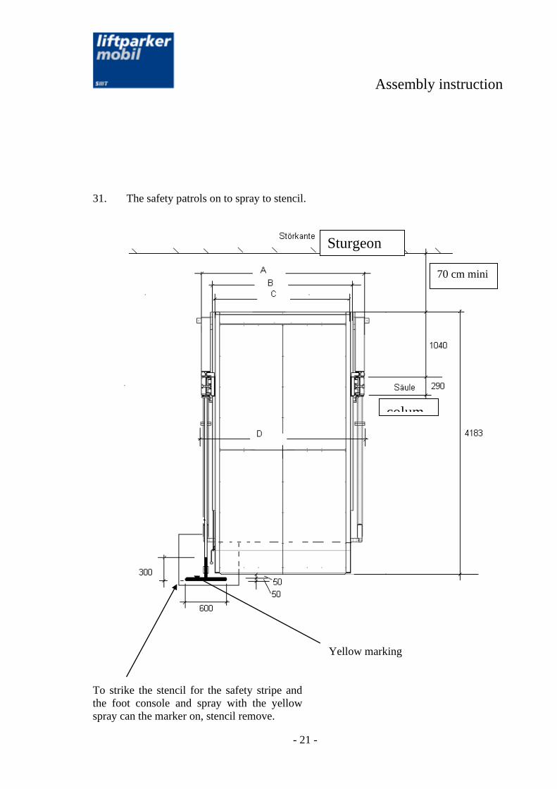
31. The safety patrols on to spray to stencil.
Yellow marking
To strike the stencil for the safety stripe and
the foot console and spray with the yellow
spray can the marker on, stencil remove.
70 cm mini
colum
n
Sturgeon
rim

Assembly instruction
- 22 -
This course of events is to make out per
parking system.

Assembly instruction
- 23 -
5 Circuit diagram:

Assembly instruction
- 24 -
6 Hydraulic drawing
Assembly instruction
- 25 -
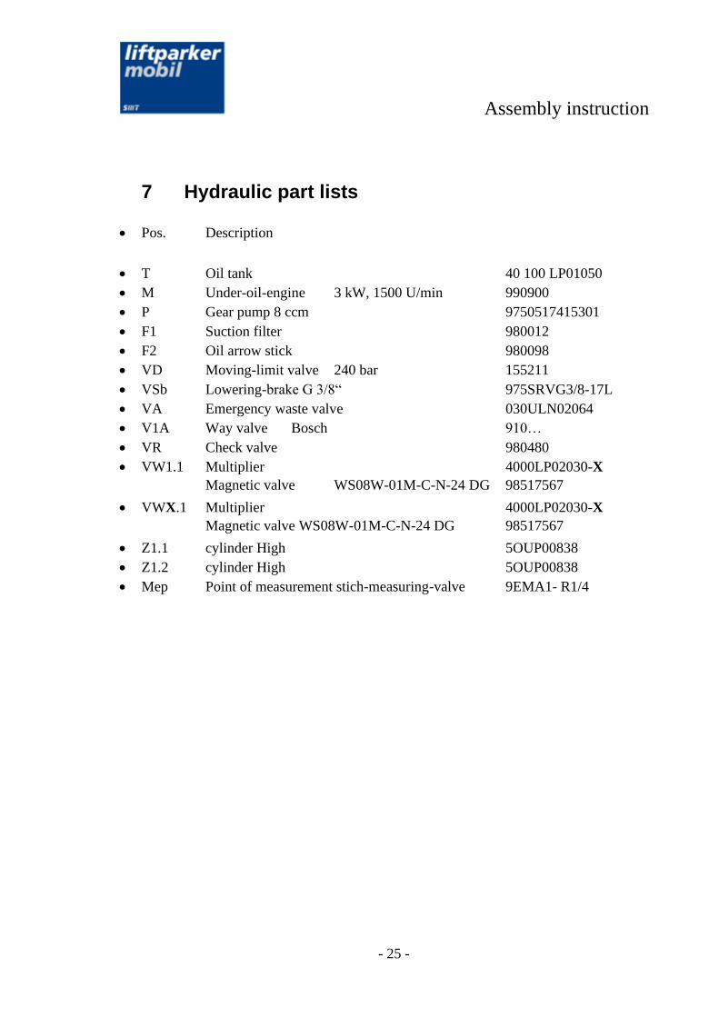
7 Hydraulic part lists
• Pos. Description
• T Oil tank 40 100 LP01050
• M Under-oil-engine 3 kW, 1500 U/min 990900
• P Gear pump 8 ccm 9750517415301
• F1 Suction filter 980012
• F2 Oil arrow stick 980098
• VD Moving-limit valve 240 bar 155211
• VSb Lowering-brake G 3/8“ 975SRVG3/8-17L
• VA Emergency waste valve 030ULN02064
• V1A Way valve Bosch 910…
• VR Check valve 980480
• VW1.1 Multiplier 4000LP02030-X
Magnetic valve WS08W-01M-C-N-24 DG 98517567
• VWX.1 Multiplier 4000LP02030-X
Magnetic valve WS08W-01M-C-N-24 DG 98517567
• Z1.1 cylinder High 5OUP00838
• Z1.2 cylinder High 5OUP00838
• Mep Point of measurement stich-measuring-valve 9EMA1- R1/4