LIFEPAK 20e Defibrillator/Monitor Performance Inspection ...
61
LIFEPAK ® 20e Defibrillator/Monitor Performance Inspection Procedure (PIP) 3201896-000_C ©2020 Stryker --- CONTENTS --- Page 1 of 61 LIFEPAK ® 20e Defibrillator/Monitor _______________________________________________________ Performance Inspection Procedure (PIP)
Transcript of LIFEPAK 20e Defibrillator/Monitor Performance Inspection ...

LIFEPAK®20e Defibrillator/Monitor Performance Inspection Procedure (PIP)
3201896-000_C ©2020 Stryker --- CONTENTS --- Page 1 of 61
LIFEPAK®20e Defibrillator/Monitor _______________________________________________________ Performance Inspection Procedure (PIP)

LIFEPAK®20e Defibrillator/Monitor Performance Inspection Procedure (PIP)
3201896-000_C ©2020 Stryker --- CONTENTS --- Page 2 of 61
This Performance Inspection Procedure (PIP) is a set of manual test procedures which are used as an operational closed-case evaluation of the LIFEPAK® 20e Defibrillator/Monitor. This section describes contents of the test procedures you will perform to determine if the device is operating within the required specifications.
Perform the PIP as part of a regularly scheduled preventive maintenance routine. Also, perform the PIP after any repair, replacement, or calibration procedure. The Performance Inspection Procedure Checklist is provided as a tool for the recording of PIP test results.
Contents:
PIP - Scope and Applicability PIP - Resource Requirements
PIP - Test Equipment PIP - Test Equipment Verification PIP - Workstation Power
PIP - Test Equipment Requirements PIP - Test Instruction
PIP - General Instruction PIP - Exterior Physical Inspection/Cleaning Paddles PIP - Device Setup PIP - Manual Mode Access PIP - Power On/Self-Test PIP - User Test and Date/Time Verification Test PIP - SpO2 PIP - Keypad Verification Tests PIP - Pixels Verification Test PIP - Audio Verification Test PIP - Printer Verification Tests PIP - ECG Performance Testing

LIFEPAK®20e Defibrillator/Monitor Performance Inspection Procedure (PIP)
3201896-000_C ©2020 Stryker --- CONTENTS --- Page 3 of 61
PIP- 3-Lead ECG Tests PIP - 3-Lead ECG Leads Off Detection Test PIP - 3-Lead ECG Gain Test
PIP - 5-Lead ECG Tests PIP- 5-Lead ECG Leads Off Detection Test PIP- 5-Lead ECG Gain Test
PIP- Analog ECG Output (Optional Test) PIP- Defibrillator/Pacing Testing
PIP - Quik-Combo Defibrillator Sync Tests at 2J PIP - QUIK-COMBO Defibrillator Delivered Energy Tests at 2J and 70 J PIP - Quik-Combo Defibrillator Delivered Energy and Charge Time Tests at 360 J (Battery Powered) PIP - Quik-Combo Defibrillator ECG Characteristic Tests
PIP - QUIK-COMBO Defibrillator ECG Gain Test PIP - QUIK-COMBO Defibrillator a Positive R-wave Test
PIP - Quik - Combo Sync Remote Test PIP - Standard Paddles Users Test PIP - Standard Paddles Defibrillator Sync Test at 2J PIP - Standard Paddles Defibrillator Delivered Energy Tests at 2J and 70J PIP - Standard Paddles Defibrillator Delivered Energy and Charge Time Tests at 360 J (Battery Powered) PIP - Standard Paddles ECG Characteristic Tests
PIP - Standard Paddles Defibrillator ECG Gain Test PIP - Standard Paddles Defibrillator a Positive R-wave Test
PIP - Standard Paddles Sync Remote Test PIP - Pacer Characteristic Tests
PIP - Pacer Leads-Off Detection Test PIP - Pacer Output Current Test PIP - Pacer Pulse Width Test
PIP - Patient Impedance Test

LIFEPAK®20e Defibrillator/Monitor Performance Inspection Procedure (PIP)
3201896-000_C ©2020 Stryker --- CONTENTS --- Page 4 of 61
Electrical Safety
PIP- Safety Analyzer Setup for IEC62353 Testing
PIP- Protect Earth Resistance Test PIP - Leakage Current Test
PIP - Leakage Current Test Setup PIP- Direct Equipment Leakage Test at Single Fault Condition (SFC) PIP- Safety Analyzer Setup on Direct Applied Part Leakage Tests PIP- Direct Applied Part Leakage Test - ECG PIP- Direct Applied Part Leakage Test -Therapy PIP- Direct Applied Part Leakage Test -SPO2 PIP - Safety Analyzer Setup on Earth Leakage Tests PIP- Earth Leakage Test at Normal Condition (NC) PIP- Earth Leakage Test at Single Fault Condition (SFC)
PIP- Restore Customer Setting

LIFEPAK®20e Defibrillator/Monitor Performance Inspection Procedure (PIP)
3201896-000_C ©2020 Stryker --- CONTENTS --- Page 5 of 61
Scope and Applicability The PIP applies to the LIFEPAK 20e Defibrillator/Monitor exclusively. To complete the PIP, you must perform the manual test outlined in the PIP - Instructions below. All PIP tests must be performed from start to finish in the order presented.
Refer to the PIP - Resource Requirements for a listing of the necessary qualifications for PIP equipment, test equipment verification, workstation power.
Refer to the PIP - Test Equipment Requirements for a listing of test equipment, including specifications, required to complete the PIP. Use the PIP - Checklist to record your results. Resource Requirements This section describes the requirements for PIP equipment, PIP test equipment verification, PIP workstation power.
Test Equipment To perform the PIP, you must use the equipment listed in the PIP - Test Equipment Requirements table. Although the table lists specific test equipment by manufacturer, test equipment with equivalent specifications may be substituted. Refer to the test equipment manufacturer’s operating instructions for usage details where not specifically covered herein.
Test Equipment Verification All test equipment used to perform the PIP must have a current calibration label. The calibration label must be issued by a certified calibration facility.
Workstation Power The AC line power to the workstation must be connected to a grounded power source.

LIFEPAK®20e Defibrillator/Monitor Performance Inspection Procedure (PIP)
3201896-000_C ©2020 Stryker --- CONTENTS --- Page 6 of 61
Test Equipment Requirements Equipment Specification or Description Manufacturer or Part number or
Catalog number Defibrillator analyzer with external noninvasive
pacer measurements*
Energy range: 0 to 450 J Load resistance: 50 ohms±1% Accuracy: +/- 2%, non-inductive
Waveforms: Simultaneous 12-lead output Rates: 30 bpm, 120 bpm, with rate accuracy of ± 1% Amplitude: 1 mV ± 5%, based on Lead II ECG performance: Amplitudes of Lead II and Leads V1-V6 are equivalent. Lead I = 70% amplitude of Lead II. Sine wave: 10 Hz @ 1 mV ± 2%, based on Lead II
Fluke® Biomedical Impulse 7000DP with QUIK-COMBO adapter accessory 16/7 D/P ADPT104**
Safety Analyzer 90 V ac rms to 264 V ac rms mains voltage Current range: 0-1999 µA Current accuracy: 5% of reading or 1 digit (whichever is greater)
Fluke Biomedical ESA612*
Decade resistance box 0 to 9 MΩ resistance box Resolution: 1 Ω; accuracy: ± 1%
IET RS-200 Resistance Substitute*
Remote Sync Test Pulse Generator ***
21300-007574
SPO2 Leakage Cable 21300-007561, 21300-005487, 21300-007562
AC Power Cable Commercial Accessory –Test Plug, Quik-Combo 11113-000002 Paddle Assembly - Detachable, LP20 11130-000037 QUIK-COMBO Therapy Cable 11110-000040 50 mm Recorder Paper 11240-000013

LIFEPAK®20e Defibrillator/Monitor Performance Inspection Procedure (PIP)
3201896-000_C ©2020 Stryker --- CONTENTS --- Page 7 of 61
Equipment Specification or Description Manufacturer or Part number or Catalog number
DB9 Male/DB 9 Female cable (optional) MXT100 Masimo Oximeter Adult finger sensor (LNOP DCI, Adult SPO2 sensor, reusable)
11171-000007
Massimo Extension Cable (PC04-Patient Cable, SPO2, 4ft)
11171-000006
Cable Assembly, Fast Patch (use for 7000DP and RS200)
11110-000052
Electrode test posts (use for 7000DP and RS200) 21330-001372
Cable, Test, Service, LP CR2 3323095
Cable Assembly, 3 Lead ECG 11110-000029 11110-000030
Cable Assembly, 5 Lead ECG 11110-000066 Cable Assembly, Analog ECG Output 11110-000067 Cable, QUIK-COMBO to Snap Termination 3009139 Adapter -Test, Paddles, Leakage, LP12 & LP20 3206631 Cable, Test, ECG snap to banana plug 3305684 QUIK-COMBO Leakage Cable 3207066 1210 Adapter (for ESA612) Fluke 1210 BJ2 ECG Input Jack Adapter (1 for ESA612 and 2 for 1210 Adapter)
Fluke - BJ2
Banana plug cable (connect between ESA612 and Battery eliminators)
Fluke ESA612 Accessory kit
*Some energy meters are not accurate for biphasic waveforms; contact your defibrillator analyzer’s manufacturer for more information. **Equivalent equipment is required to meet the specifications listed in the specification column. ***A function generator can be used alternatively to the Remote Sync Test Pulse Generator.

LIFEPAK®20e Defibrillator/Monitor Performance Inspection Procedure (PIP)
3201896-000_C ©2020 Stryker --- CONTENTS --- Page 8 of 61
Test Instructions PIP - General Instruction
• This section lists the general instructions for performing the Performance Inspection Procedure (PIP).
• Perform the PIP in the order presented.
• Use the Performance Inspection Procedure Checklist to record your results.
WARNING POSSIBLE EQUIPMENT DAMAGE
Only use accessories approved by Physio-Control.

LIFEPAK®20e Defibrillator/Monitor Performance Inspection Procedure (PIP)
3201896-000_C ©2020 Stryker --- CONTENTS --- Page 9 of 61
PIP - Exterior Physical Inspection/Cleaning Paddles To perform an exterior physical inspection:
1. Inspect the LIFEPAK 20e exterior for the following: Damage, excessive wear, improper mechanical function, and damaged connectors.
2. Pick up and turn over the device and listen for loose or rattling hardware. Locate any loose or rattling hardware, and then tighten or replace it.
3. Inspect the rubber feet on the underside of the lower enclosure. Reinstall or replace rubber feet as necessary. 4. Inspect the Therapy, ECG, SpO2 (if equipped), DB-9, DB-15, AED door, and IrDA connectors for damage and or cracks. 5. Inspect the keypads and overlays for damage, cracks, and separations. 6. Check all other accessory cables, Paddles, ECG, SpO2 sensors, and related items for expiration dates, general condition, and
suitability for use. 7. Inspect carrying strap and mounts (if the device is equipped with them).
To perform Cleaning Paddles:
1. Disconnect the adult paddle plate from the paddle assembly. 2. Clean the spring contact of the adult paddle with alcohol. 3. Clean the pediatric electrode surface with alcohol. 4. Reattach the adult paddle plate to the paddle assembly.

LIFEPAK®20e Defibrillator/Monitor Performance Inspection Procedure (PIP)
3201896-000_C ©2020 Stryker --- CONTENTS --- Page 10 of 61
PIP - Device Setup
WARNING SHOCK HAZARD
The defibrillator delivers up to 360 joules of electrical energy. Unless properly used as described in these operating instructions, this energy may cause serious injury or death. Do not attempt to operate this device unless thoroughly familiar with these operating instructions and the function of all controls, indicators, connectors, and accessories.
1. Connect the AC Power cable into the device. 2. Install a roll of printer paper into the printer.
Figure 1.1: Device Setup

LIFEPAK®20e Defibrillator/Monitor Performance Inspection Procedure (PIP)
3201896-000_C ©2020 Stryker --- CONTENTS --- Page 11 of 61
PIP - Manual Mode Access
It is recommended that the device be set up for Manual mode when performing the PIP. Note: If you do not wish to change the setup for a device configured with manual access restrictions, it may be necessary to use the reserved technician passcode of 5433 to gain access to Manual mode. Note: Be sure to make note of the customer settings to restore the device to the user-selected MANUAL ACCESS configuration at the completion of this PIP. To perform the device for Manual mode access: 1. Access the Setup mode as follows:
a. Press and hold OPTIONS and EVENT, and then turn the device ON. b. When the Setup mode passcode prompt appears enter 5433.
2. Select MANUAL MODE in the Setup menu. 3. In the Setup/Manual Mode submenu, set the Manual Access selection to
Manual/Direct as shown in Figure 1.2. 4. Turn the device OFF by pressing ON for two seconds.
Figure 1.2: Manual Mode Access

LIFEPAK®20e Defibrillator/Monitor Performance Inspection Procedure (PIP)
3201896-000_C ©2020 Stryker --- CONTENTS --- Page 12 of 61
PIP - Power Self-Test To perform the Power On/Self-Test:
1. Press the ON button to initiate the device nominal five-second power-on self-
test routine. Listen for a single tone from the speaker and then three distinct beeps from the sonalert (AC loss alert).
2. Verify that all lamps light momentarily except for the ON and AC mains indicators which remain on throughout self-test.
Note: The initial display indicates self-test in progress, as shown in Figure 1.3.
3. Verify that the device completes the Power On sequence. 4. Verify that AC Main indicator remains ON. 5. Verify that the SERVICE INDICATOR is OFF.
Figure 1.3: Power Self -Test

LIFEPAK®20e Defibrillator/Monitor Performance Inspection Procedure (PIP)
3201896-000_C ©2020 Stryker --- CONTENTS --- Page 13 of 61
PIP - User Test and Date/Time Verification Tests To perform the User Test and Date/Time Verification Tests:
1. Connect the Quik-Combo and Test Plug into the device. 2. Turn the device ON. 3. Press OPTIONS to access the Options menu. 4. Select USER TEST from the Option menu. When asked to Start user test.
Select Yes and confirm using the Speed Dial. 5. Confirm the printed results that the device passes the user test and that the
correct date and time values are displayed on the printout as shown in Figure 1.4.
Note: If the date and time are incorrect, reset using the Options/Date/Time menu.
6. Turn the device OFF.
Figure 1.4: User Test and Date/Time Printout

LIFEPAK®20e Defibrillator/Monitor Performance Inspection Procedure (PIP)
3201896-000_C ©2020 Stryker --- CONTENTS --- Page 14 of 61
PIP - SPO2 Test To perform SPO2 Test:
1. Turn the device ON. 2. Connect the SpO2 finger probe to the SpO2 connector as shown in Figure 1.5. 3. Verify the SpO2 parameter region appears on the display. 4. Place your index finger into the SpO2 finger probe. Allow several seconds for the probe to
find your pulse. 5. Confirm the SpO2 reading is between 50 % to 100 %. 6. Remove finger from SpO2 finger probe. Message should display on screen: SpO2 Check
Sensor with audible alarm. 7. Unplug SpO2 finger probe from the device; while on current patient record, message should
display: SpO2 No Sensor Detected. Note: Alarms will clear when device is turned off and new patient record started the next time the device is turned on again.
8. Turn the device OFF.
Figure 1.5: SPO2 Test

LIFEPAK®20e Defibrillator/Monitor Performance Inspection Procedure (PIP)
3201896-000_C ©2020 Stryker --- CONTENTS --- Page 15 of 61
PIP - Keypad Verification Tests To perform Keypad Verification Tests:
1. Select TESTS in the Service menu. 2. Select BUTTONS in the Service/Tests submenu as shown in Figure 1.6. 3. Press each front panel button when prompted by the flashing button
legend (although you may press the buttons in any order). 4. Verify with each button pressed that its associated text box is highlighted.
Note: A failure is indicated by a text box that is not highlighted. It is normal for the buttons with up/down arrows to highlight only the arrows.
5. Press the switch located between the OPTIONS and PAUSE buttons. Note: The switch is hidden in the elastomer keypad.
6. Verify the TEST COMPLETE message appears on the bottom of the screen and the Service LED is not on.
7. Press the SPEED DIAL to exit at the end of the test. 8. Continue with the next test while still in Service mode.
Figure 1.6: Keypad Test

LIFEPAK®20e Defibrillator/Monitor Performance Inspection Procedure (PIP)
3201896-000_C ©2020 Stryker --- CONTENTS --- Page 16 of 61
PIP - Pixels Verification Test To perform Pixels Verification Test:
1. Select TESTS in the Service menu. 2. Select PIXELS in the Service/Tests submenu. The pixels test screen appears, as shown
in Figure 1.7. 3. Carefully examine the screen for any anomalies. Rotate SPEED DIAL to scroll through
test screens. 4. Press the SPEED DIAL to exit the test. 5. Continue with the next test while still in Service mode.
Figure 1.7: Pixels Test

LIFEPAK®20e Defibrillator/Monitor Performance Inspection Procedure (PIP)
3201896-000_C ©2020 Stryker --- CONTENTS --- Page 17 of 61
PIP - Audio Verification Test To perform Audio Verification Test:
1. Select VOICE/TONE from the Service/Tests submenu as shown in Figure
1.8. 2. Select START to produce voice prompts from the speaker. 3. Confirm that the voice prompts are clearly audible and reproduced without
distortion. Note: You can listen to a complete replay of all voice prompts and tones, but it is not required for verification of this function.
4. Continue with the next test while still in Service mode.
Figure 1.8: Audio Test

LIFEPAK®20e Defibrillator/Monitor Performance Inspection Procedure (PIP)
3201896-000_C ©2020 Stryker --- CONTENTS --- Page 18 of 61
Printer Verification @ 25 mm/sec 1. Select PRINTER in the Service/Tests submenu. 2. Select START to print a test strip. 3. Inspect the test strip for the following attributes:
a. The large “X” form prints without missing dots. b. Four horizontal lines print (one very close to the lower paper margin). c. The character set prints clearly without broken characters. d. Vertical lines spaced 25 mm ±1mm (approx. 24 to 26 mm.) apart print
correctly. 4. Open the printer door and verify the CHECK PRINTER message appears at
the bottom of the screen. 5. Remove the printer paper, and then close the printer door. 6. Verify the CHECK PRINTER message appears at the bottom of the screen. 7. Select PREVIOUS PAGE twice to return to the Service menu. 8. Continue with the next test.
Figure 1.9: Printer Test

LIFEPAK®20e Defibrillator/Monitor Performance Inspection Procedure (PIP)
3201896-000_C ©2020 Stryker --- CONTENTS --- Page 19 of 61
PIP - ECG Performance Testing
ECG Performance Testing consist of:
PIP - ECG Performance Testing PIP - 3-Lead ECG Tests
PIP - 3-Lead ECG Leads Off Detection Test PIP - 3-Lead ECG Gain Test
PIP- 5-Lead ECG Tests PIP - 5-Lead ECG Leads Off Detection Test PIP - 5-Lead ECG Gain Test

LIFEPAK®20e Defibrillator/Monitor Performance Inspection Procedure (PIP)
3201896-000_C ©2020 Stryker --- CONTENTS --- Page 20 of 61
PIP - 3-Lead ECG Tests Note: Perform this test if 3-lead ECG cable is used. Otherwise, skip to the next test. The 3-Lead ECG tests consist of:
PIP - 3-Lead ECG Leads Off Detection Test PIP - 3-Lead ECG Gain Test PIP - 3-Lead ECG Leads Off Detection Test 1. Connect the 3-Lead ECG cable between the device and Impulse 7000DP as
shown in Figure 1.10. 2. Set the Impulse 7000DP output to a 1-mv, 10-Hz sine wave. 3. Set the device LEAD selection to Lead II. 4. Remove the LA lead from the Impulse 7000DP, and verify the device displays
the ECG LEADS OFF message and a repeating priority 3 tone shall sound when the Lead is removed. Reconnect the LA lead.
5. Remove the RA lead from the Impulse 7000DP, and verify the device displays the RA LEADS OFF message and a repeating priority 3 tone shall sound when the Lead is removed. Reconnect the RA lead.
6. Remove the LL lead from the Impulse 7000DP, and verify the device displays the LL LEADS OFF message and a repeating priority 3 tone shall sound when the Lead is removed. Reconnect the LL lead.
7. Continue with the next test with this setup in place.
Figure 1.10: 3 Lead ECG Leads Test Setup

LIFEPAK®20e Defibrillator/Monitor Performance Inspection Procedure (PIP)
3201896-000_C ©2020 Stryker --- CONTENTS --- Page 21 of 61
PIP - 3- Lead ECG Gain Test To perform 3-Lead ECG Gain Test:
1. Set the Impulse 7000DP output to a 1-mv, 10-Hz sine wave. 2. Set the device ECG SIZE to 4.0. 3. Set the device LEAD selection to LEAD I. 4. Print five seconds of ECG Lead I and confirm the printed signal amplitude is 25 mm to
31 mm, peak-to-peak as shown in Figure 1.11. 5. Set the device LEAD selection to LEAD II. 6. Print five seconds of ECG Lead II and confirm the printed signal amplitude is 36 mm to
44 mm, peak-to-peak as shown in Figure 1.11. 7. Turn the printer OFF
Figure 1.11: ECG Gain at Lead I and Lead II
LIFEPAK®20e Defibrillator/Monitor Performance Inspection Procedure (PIP)
3201896-000_C ©2020 Stryker --- CONTENTS --- Page 22 of 61
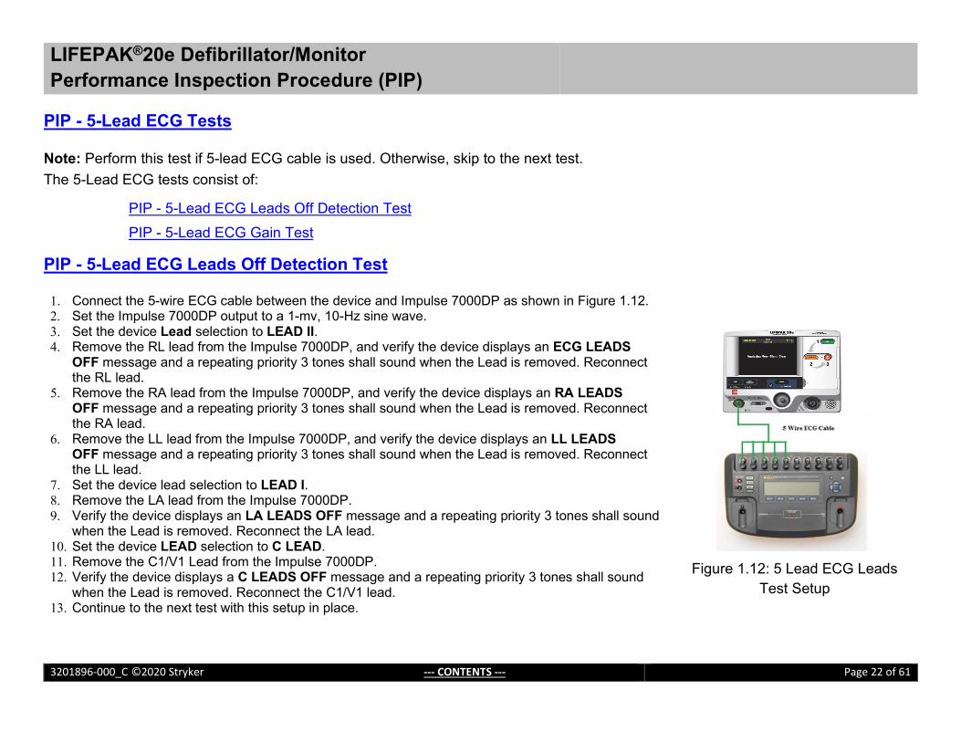
PIP - 5-Lead ECG Tests Note: Perform this test if 5-lead ECG cable is used. Otherwise, skip to the next test. The 5-Lead ECG tests consist of:
PIP - 5-Lead ECG Leads Off Detection Test PIP - 5-Lead ECG Gain Test PIP - 5-Lead ECG Leads Off Detection Test 1. Connect the 5-wire ECG cable between the device and Impulse 7000DP as shown in Figure 1.12. 2. Set the Impulse 7000DP output to a 1-mv, 10-Hz sine wave. 3. Set the device Lead selection to LEAD II. 4. Remove the RL lead from the Impulse 7000DP, and verify the device displays an ECG LEADS
OFF message and a repeating priority 3 tones shall sound when the Lead is removed. Reconnect the RL lead.
5. Remove the RA lead from the Impulse 7000DP, and verify the device displays an RA LEADS OFF message and a repeating priority 3 tones shall sound when the Lead is removed. Reconnect the RA lead.
6. Remove the LL lead from the Impulse 7000DP, and verify the device displays an LL LEADS OFF message and a repeating priority 3 tones shall sound when the Lead is removed. Reconnect the LL lead.
7. Set the device lead selection to LEAD I. 8. Remove the LA lead from the Impulse 7000DP. 9. Verify the device displays an LA LEADS OFF message and a repeating priority 3 tones shall sound
when the Lead is removed. Reconnect the LA lead. 10. Set the device LEAD selection to C LEAD. 11. Remove the C1/V1 Lead from the Impulse 7000DP. 12. Verify the device displays a C LEADS OFF message and a repeating priority 3 tones shall sound
when the Lead is removed. Reconnect the C1/V1 lead. 13. Continue to the next test with this setup in place.
Figure 1.12: 5 Lead ECG Leads Test Setup

LIFEPAK®20e Defibrillator/Monitor Performance Inspection Procedure (PIP)
3201896-000_C ©2020 Stryker --- CONTENTS --- Page 23 of 61
PIP - 5- Lead ECG Gain Test To perform 5-Lead ECG Gain Test:
1. Set the Impulse 7000DP output to a 1-mv, 10-Hz sine wave. 2. Set the device ECG SIZE to 4.0. 3. Set the device LEAD selection to LEAD I. 4. Print five seconds of ECG Lead I and confirm the printed signal
amplitude is 25 mm to 31 mm, peak-to-peak as shown in Figure 1.13. 5. Set the device LEAD selection to LEAD II. 6. Print five seconds of ECG Lead II and confirm the printed signal
amplitude is 36 mm to 44 mm, peak-to-peak as shown in Figure 1.13. 7. Repeat steps 5 and 6 for C Lead. 8. Turn the printer OFF.
Figure 1.13: ECG Gain at Lead I and Lead II

LIFEPAK®20e Defibrillator/Monitor Performance Inspection Procedure (PIP)
3201896-000_C ©2020 Stryker --- CONTENTS --- Page 24 of 61
PIP - Analog ECG Output Test (Optional) Note: Perform this test if this feature is used by the customer. Otherwise, skip to the next test.
To perform Analog ECG Output Test:
1. Connect the device to the Impulse 7000DP and oscilloscope as shown in Figure 1.14.
2. Turn the device ON. 3. Using the ECG cable supplied with the device input a
1-mV, 10-Hz sine wave from the Impulse 7000DP. 4. Set device LEAD selection to LEAD II.
Note: The Analog ECG output is in real time at a nominal 1 V/mV and is not affected by the device ECG SIZE setting.
5. Verify the amplitude of the signal displayed on the oscilloscope is between 0.90Vp-p and 1.10Vp-p.
6. Disconnect the ECG output cable from the device and oscilloscope.
7. Turn the device OFF. Figure 1.14: Analog ECG Output Test Setup

LIFEPAK®20e Defibrillator/Monitor Performance Inspection Procedure (PIP)
3201896-000_C ©2020 Stryker --- CONTENTS --- Page 25 of 61
PIP- Defibrillator/Pacing Testing
The Defibrillator/Pacing Testing consist of: PIP - Quik-Combo Defibrillator Sync Tests at 2J PIP - QUIK-COMBO Defibrillator Delivered Energy Tests at 2J and 70 J PIP - Quik-Combo Defibrillator Delivered Energy and Charge Time Tests at 360 J (Battery Powered) PIP - Quik-Combo Defibrillator ECG Characteristic Tests
PIP - QUIK-COMBO Defibrillator ECG Gain Test PIP - QUIK-COMBO Defibrillator a Positive R-wave Test
PIP - Quik - Combo Sync Remote Test PIP - Standard Paddles Users Test PIP - Standard Paddles Defibrillator Sync Test at 2J PIP - Standard Paddles Defibrillator Delivered Energy Tests at 2J and 70J PIP - Standard Paddles Defibrillator Delivered Energy and Charge Time Tests at 360 J (Battery Powered) PIP - Standard Paddles ECG Characteristic Tests
PIP - Standard Paddles Defibrillator ECG Gain Test PIP - Standard Paddles Defibrillator a Positive R-wave Test
PIP - Standard Paddles Sync Remote Test PIP - Pacer Characteristic Tests
PIP - Pacer Leads-Off Detection Test PIP - Pacer Output Current Test PIP - Pacer Pulse Width Test

LIFEPAK®20e Defibrillator/Monitor Performance Inspection Procedure (PIP)
3201896-000_C ©2020 Stryker --- CONTENTS --- Page 26 of 61
PIP - QUIK-COMBO Defibrillator Sync Test at 2J To perform QUIK- COMBO Defibrillator Sync Test at 2J: Note: Perform this test if Quik-Combo cable is used. Otherwise, skip to the next test. To perform Quik-Combo Defibrillator Sync Test at 2 J:
1. Establish the setup as shown in Figure 1.15.
Note: Ensure proper test setup connections to the Defibrillator Analyzer. To avoid damage to the Analyzer or defibrillator, do NOT apply defibrillator pulses to the pacer inputs of the analyzer.
2. Turn the device ON. 3. Set the device: Manual mode, ECG Size to 1.0, LEAD selection to Lead II. 4. Set the Defibrillator Analyzer to measure SYNC. 5. Press the SYNC button ON and select LOCAL, if Remote Sync is set to on. 6. Verify the Sync LED turns on and R-wave markers appear on the ECG waveform. 7. Press the ENERGY SELECT button to select 2J. 8. Press the CHARGE button and wait for the device to reach full charge. Then push
the SHOCK button to discharge the device. 9. Verify the defibrillator analyzer measures a sync R-wave is within 1.0 ms to 60ms. 10. Continue to the next test with this setup in place.
Figure 1.15: Quik-Combo Defibrillator Delivered Energy Setup

LIFEPAK®20e Defibrillator/Monitor Performance Inspection Procedure (PIP)
3201896-000_C ©2020 Stryker --- CONTENTS --- Page 27 of 61
PIP - QUIK-COMBO Defibrillator Delivered Energy Tests at 2J and 70 J To perform QUIK- COMBO Defibrillator Delivered Energy Test at 2J and 70J:
1. Set the Defibrillator Analyzer to measure ENRG 2. Press ENERGY SELECT on the device and select 2 J. 3. Press the CHARGE button and wait for the device to reach full charge. Then push the SHOCK button to discharge the device. 4. Verify the defibrillator analyzer indicates the delivered energy is within 1.0 J to 3.0J. 5. Repeat steps 2 and 3 for the energy level at 70J. 6. Verify the defibrillator analyzer indicates the delivered energy is within 59.5 J to 80.5J.
Note: Perform the TCP- Defibrillator Energy Calibration if the delivered energy falls outside of the acceptable output range.

LIFEPAK®20e Defibrillator/Monitor Performance Inspection Procedure (PIP)
3201896-000_C ©2020 Stryker --- CONTENTS --- Page 28 of 61
PIP - QUIK-COMBO Defibrillator Delivered Energy and Charge Time Tests at 360J (Battery Powered) Note: Perform this test if Quik-Combo cable is used. Otherwise, skip to the next test. WARNING SHOCK HAZARD
Electrical energy is discharged during this procedure. Do not allow the electrodes to contact any person or conductive surface except as described below.
To perform Quik-Combo Defibrillator Delivered Energy and Charge Time Tests at 360 J (Battery Powered)
1. Establish the setup as shown in Figure 1.16. 2. Disconnect the AC power cable from the device and turn the device ON by battery. 3. Press ENERGY SELECT on the device and select 360 J. 4. Start a Stopwatch, then press the CHARGE button and wait for the device to reach
full charge. Stop a Stopwatch, and then press the SHOCK button to discharge the device.
5. Verify the defibrillator analyzer indicates the delivered energy is within 306.0J to 414.0 J.
6. Verify the Charge Time is within 1s to 10 s. Note: Perform the TCP- Defibrillator Energy Calibration if the delivered energy falls outside of the acceptable output range.
7. After testing is complete reconnect the AC power cable to the device.
Figure 1.16: Quik-Combo Defibrillator Energy and Charge Time Test Setup

LIFEPAK®20e Defibrillator/Monitor Performance Inspection Procedure (PIP)
3201896-000_C ©2020 Stryker --- CONTENTS --- Page 29 of 61
PIP - Quik-Combo Defibrillator ECG Characteristic Tests Note: Perform this test if Quik-Combo cable is used. Otherwise, skip to the next test.
The ECG characteristic tests consist of ECG gain and a positive R-wave test. These two tests are included here as a single procedure and step numbers are continuous from one step to the next.
PIP - QUIK-COMBO Defibrillator ECG Gain Test PIP - QUIK-COMBO Defibrillator a Positive R-wave Test PIP - Quik-Combo Defibrillator ECG Gain Test To perform ECG Gain Test:
1. Set the Impulse 7000DP output to ECG, Performance, 1-mv, 10-Hz sine wave.
2. Set the device ECG SIZE to 4.0. 3. Set the LEAD selection to PADDLES. 4. Print 10 seconds of paddles ECG and confirm the printed signal amplitude
is 36 mm to 44 mm, peak-to-peak as shown in Figure 1.17.
Figure 1.17: ECG Gain at Paddles Lead
LIFEPAK®20e Defibrillator/Monitor Performance Inspection Procedure (PIP)
3201896-000_C ©2020 Stryker --- CONTENTS --- Page 30 of 61
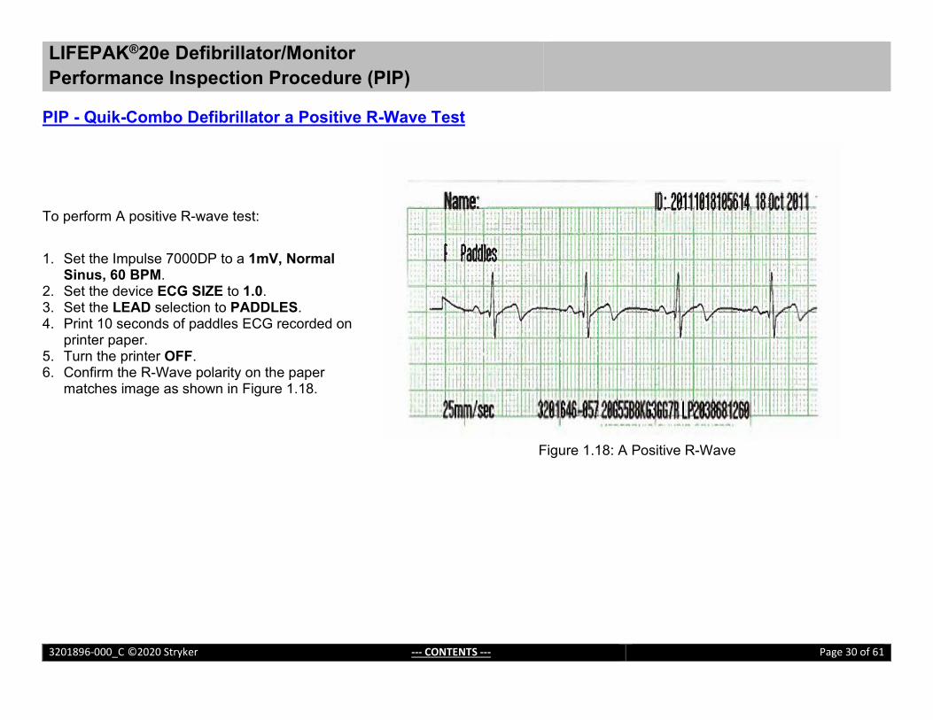
PIP - Quik-Combo Defibrillator a Positive R-Wave Test To perform A positive R-wave test:
1. Set the Impulse 7000DP to a 1mV, Normal Sinus, 60 BPM.
2. Set the device ECG SIZE to 1.0. 3. Set the LEAD selection to PADDLES. 4. Print 10 seconds of paddles ECG recorded on
printer paper. 5. Turn the printer OFF. 6. Confirm the R-Wave polarity on the paper
matches image as shown in Figure 1.18.
Figure 1.18: A Positive R-Wave

LIFEPAK®20e Defibrillator/Monitor Performance Inspection Procedure (PIP)
3201896-000_C ©2020 Stryker --- CONTENTS --- Page 31 of 61
PIP - Quik-Combo Sync Remote Test Note: Perform this test if Quik-Combo cable is used. Otherwise, skip to the next test. To perform Quik-Combo Sync Remote Test:
1. Establish the setup as shown in Figure 1.19. 2. Turn on the Remote Sync Test Pulse Generator.
Note: A function generator set to provide a pulse train 5 Vp-p (0-5 V), 5 to 200 ms wide, 120 PPM (2 Hz) can be used alternatively to the Remote Sync Test Pulse Generator.
3. On the Manual Mode setup page; set the device to Remote Sync ON.
4. Turn the device OFF and then turn the device ON. 5. Set the device: Manual mode, lead selection to PADDLES. 6. Press the SYNC button on the device. 7. On the Sync mode screen, select REMOTE. 8. Verify the SYNC LED is flashing. 9. Charge the device to 200 J. 10. Upon reaching full charge, press the SHOCK button to discharge
the device. 11. Verify the device displays "ENERGY DELIVERED" screen
message (for SW-20 version or below) or switches out of remote sync mode (for SW-26 or above).
12. On the Manual Mode setup page, set the device to Remote Sync OFF.
13. Turn the device OFF.
Figure 1.19: Quik-Combo Sync Remote Test Setup

LIFEPAK®20e Defibrillator/Monitor Performance Inspection Procedure (PIP)
3201896-000_C ©2020 Stryker --- CONTENTS --- Page 32 of 61
PIP - Standard Paddles User Test Perform this test if STANDARD paddles are used. Otherwise, skip to the next test. Note: Use the customer’s standard paddles (when available). Remove the paddles and check that the paddle surfaces and paddle wells are clean and dry and free of any debris. Verify that the metal surface of the standard paddles and paddle test contacts in the device paddle wells are free of burn and arc marks. Also check that these surfaces are free of pits, scratches or raised nicks that can be felt with the fingertip. Check the therapy connector interface for pin damage. WARNING
SHOCK HAZARD The conductive gel (wet or dry) on the paddle handles and in the paddle wells may allow the electrical energy to arc between paddles during discharge. Thoroughly clean and dry the paddles and the paddle wells after use and before performing the Standard Paddles User Test.
1. Connect the standard paddles to the device. Place the paddles in the paddle wells as shown in Figure 1.20.
2. Turn the device ON. 3. Set the device Lead selection to PADDLES. 4. Press the OPTIONS button and select USER TEST from the Option
screen. 5. Select YES from the Option/User Test screen. 6. Push Speed Dial to initialize the Self-Test and the User Test. The Self-
Test and the User Test are performed. The User Test Succeeded report is printed when test is complete. Note: The Device will automatically turn off after successfully completing the test.
7. Proceed to next test.
Figure 1.20: Standard Paddles User Test Setup

LIFEPAK®20e Defibrillator/Monitor Performance Inspection Procedure (PIP)
3201896-000_C ©2020 Stryker --- CONTENTS --- Page 33 of 61
PIP- Standard Paddles Defibrillator Sync Test at 2J Perform this test only if the device is equipped with the standard paddles option. WARNING SHOCK HAZARD
Electrical energy is discharged during this procedure. Do not allow the electrodes to contact any person or conductive surface except as described below.
Note: Ensure that the Standard Paddles is connected between the device and the Impulse 7000 DP, using the appropriate adapters. Note: Verify that the metal surface of the paddles are free of burn or arc marks and are free of pits, scratches, insulting films, contaminants or raised nicks that can be felt with the fingertip. Note: To avoid damage to the Defibrillator Analyzer, do not apply any defibrillator pulses to the pacer inputs of the analyzer.

LIFEPAK®20e Defibrillator/Monitor Performance Inspection Procedure (PIP)
3201896-000_C ©2020 Stryker --- CONTENTS --- Page 34 of 61
To perform Standard Paddles Sync Test at 2J
1. Establish the setup as shown in Figure 1.21. 2. Turn the device ON. 3. Set the device: MANUAL MODE, ECG Size to 1.0, LEAD selection to
LEAD II. 4. Set the Defibrillator Analyzer to measure SYNC. 5. Press the SYNC button ON and select LOCAL, if Remote Sync is set to on. 6. Verify the Sync LED turns on and R-wave markers appear on the ECG
waveform. 7. Press the ENERGY SELECT button to select 2J. 8. Press the CHARGE button on Standard Paddles and wait for the device to
reach full charge. Then push both SHOCK buttons on Standard Paddles to discharge the device.
9. Verify the defibrillator analyzer measures a sync R-wave is within 1.0 ms to 60ms.
10. Continue to the next test with this setup in place.
Figure 1.21: Standard Paddles Defibrillator Energy Test Setup

LIFEPAK®20e Defibrillator/Monitor Performance Inspection Procedure (PIP)
3201896-000_C ©2020 Stryker --- CONTENTS --- Page 35 of 61
PIP - Standard Paddles Defibrillator Delivered Energy Tests at 2 J and 70 J To perform Standard Paddles Defibrillator Delivered Energy Test at 2J and 70J:
1. Set the Defibrillator Analyzer to measure ENRG 2. Press ENERGY SELECT on the device and select 2 J. 3. Press the CHARGE button on Standard Paddles and wait for the device to reach full charge. Then push both SHOCK
buttons on Standard Paddles to discharge the device. 4. Verify the defibrillator analyzer indicates the delivered energy is within 1.0 J to 3.0J. 5. Repeat steps 2 and 3 for the energy level at 70J. 6. Verify the defibrillator analyzer indicates the delivered energy is within 59.5 J to 80.5J.
Note: Perform the TCP- Defibrillator Energy Calibration if the delivered energy falls outside of the acceptable output range.

LIFEPAK®20e Defibrillator/Monitor Performance Inspection Procedure (PIP)
3201896-000_C ©2020 Stryker --- CONTENTS --- Page 36 of 61
PIP - Standard Paddles Defibrillator Delivered Energy and Charge Time Tests at 360J (Battery Powered) WARNING
SHOCK HAZARD Electrical energy is discharged during this procedure. Do not allow the electrodes to contact any person or conductive surface except as described below.
To perform Standard Paddles Defibrillator Delivered Energy and Charge Time Tests at 360J (Battery Powered) 1. Establish the setup as shown in Figure 1.22. 2. Disconnect the AC power cable from the device and turn the
device ON by battery. 3. Press the ENERGY SELECT button to select 360 J. 4. Start a Stopwatch, then press the CHARGE button on Standard Paddles
and wait for the device to reach full charge. Stop a Stopwatch, and then push both SHOCK buttons on Standard Paddles to discharge the device.
5. Verify the defibrillator analyzer indicates the delivered energy is within 306.0 J to 414.0 J.
6. Verify the Charge Time is within 1s to 10 s. Note: Perform the TCP- Defibrillator Energy Calibration if the delivered energy falls outside of the acceptable output range.
7. After testing is complete reconnect the AC power cable to the device.
Figure 1.22: Standard Paddles Defibrillator
Energy and Charge Time Test Setup

LIFEPAK®20e Defibrillator/Monitor Performance Inspection Procedure (PIP)
3201896-000_C ©2020 Stryker --- CONTENTS --- Page 37 of 61
PIP - Standard Paddles Defibrillator ECG Characteristic Tests Note: Perform this test if Standard Paddles cable is used. Otherwise, skip to the next test.
The ECG characteristic tests consist of ECG gain and a positive R-wave test. These two tests are included here as a single procedure and step numbers are continuous from one step to the next.
PIP - Standard Paddles Defibrillator ECG Gain Test
PIP - Standard Paddles Defibrillator a Positive R-wave Test PIP - Standard Paddles Defibrillator ECG Gain Test To perform ECG Gain Test:
1. Set the Impulse 7000DP output to ECG, Performance, 1-mv, 10-Hz sine wave. 2. Set the device ECG SIZE to 4.0. 3. Set the LEAD selection to PADDLES. 4. Print 10 seconds of paddles ECG and confirm the printed signal amplitude is 36
mm to 44 mm, peak-to-peak as shown in Figure 1.23.
Figure 1.23:
ECG Gain of STD Paddles

LIFEPAK®20e Defibrillator/Monitor Performance Inspection Procedure (PIP)
3201896-000_C ©2020 Stryker --- CONTENTS --- Page 38 of 61
PIP - Standard Paddles Defibrillator a Positive R-Wave Test To perform A positive R-wave test:
1. Set the Impulse 7000DP to a 1mV, Normal Sinus, 60 BPM. 2. Set the device ECG SIZE to 1.0. 3. Set the LEAD selection to PADDLES. 4. Print 10 seconds of paddles ECG recorded on printer
paper. 5. Turn the printer OFF. 6. Confirm the R-Wave polarity on the paper matches image
as shown in Figure 1.24.
Figure 1.24: A Positive R-Wave

LIFEPAK®20e Defibrillator/Monitor Performance Inspection Procedure (PIP)
3201896-000_C ©2020 Stryker --- CONTENTS --- Page 39 of 61
PIP - Standard Paddles Sync Remote Test Note: Perform this test if Standard Paddles is used. Otherwise, skip to the next test. To perform Standard Paddles, Sync Remote Test: 1. Establish the setup as shown in Figure 1.25. 2. Turn on the Remote Sync Test Pulse Generator.
Note: A function generator set to provide a pulse train 5 Vp-p (0-5 V), 5 to 200 ms wide, 120 PPM (2 Hz) can be used alternatively to the Remote Sync Test Pulse Generator.
3. On the Manual Mode setup page; set the device to Remote Sync ON. 4. Turn the device OFF and then turn the device ON. 5. Set the device: Manual mode, lead selection to PADDLES. 6. Press the SYNC button on the device. 7. On the Sync mode screen, select REMOTE. 8. Verify the SYNC LED is flashing. 9. Charge the device to 200 J. 10. Upon reaching full charge, press the SHOCK button to discharge the device. 11. Verify the device displays "ENERGY DELIVERED" screen message (for SW-
20 version or below) or switches out of remote sync mode (for SW-26 or above).
12. On the Manual Mode setup page, set the device to Remote Sync OFF. 13. Turn the device OFF
Figure 1.25: Standard Paddles Sync
Remote Test Setup

LIFEPAK®20e Defibrillator/Monitor Performance Inspection Procedure (PIP)
3201896-000_C ©2020 Stryker --- CONTENTS --- Page 40 of 61
PIP – Pacer Characteristic Tests
The pacer characteristics consist of:
PIP – Pacer Leads-Off Detection Test PIP – Pacer Output Current Test PIP – Pacer Pulse Width Test

LIFEPAK®20e Defibrillator/Monitor Performance Inspection Procedure (PIP)
3201896-000_C ©2020 Stryker --- CONTENTS --- Page 41 of 61
PIP – Pacer Leads-Off Detection Test To perform Pacer Leads-Off detection: 1. Establish the setup as shown in Figure 1.26.
Note: Can use any type of ECG Lead cable in the setup. 2. Turn the device ON. 3. Set the Impulse 7000DP to measure Pacer 4. Press PACER button, press F1/Brand to Physio Control, press F2/Input to Defib,
and press F3/Load to 50 ohms. 5. Press PACER on the device. 6. Verify the PACER LED is on and the Pacer overlay appears. 7. Disconnect one of the test post adapter snaps from the Impulse 7000DP. 8. Verify the Pacing/Connect Electrodes overlay appears, accompanied by an audible
alarm. 9. Reconnect the test post adapter snap. 10. Verify the Pacing/Connect Electrodes overlay disappears and the alarm stops.
Figure 1.26: Pacer Test Setup
LIFEPAK®20e Defibrillator/Monitor Performance Inspection Procedure (PIP)
3201896-000_C ©2020 Stryker --- CONTENTS --- Page 42 of 61
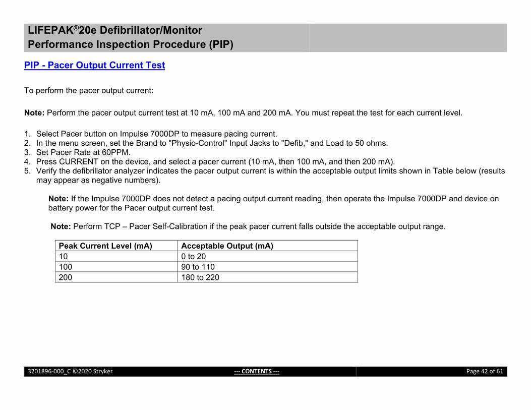
PIP - Pacer Output Current Test To perform the pacer output current:
Note: Perform the pacer output current test at 10 mA, 100 mA and 200 mA. You must repeat the test for each current level. 1. Select Pacer button on Impulse 7000DP to measure pacing current. 2. In the menu screen, set the Brand to "Physio-Control" Input Jacks to "Defib," and Load to 50 ohms. 3. Set Pacer Rate at 60PPM. 4. Press CURRENT on the device, and select a pacer current (10 mA, then 100 mA, and then 200 mA). 5. Verify the defibrillator analyzer indicates the pacer output current is within the acceptable output limits shown in Table below (results
may appear as negative numbers).
Note: If the Impulse 7000DP does not detect a pacing output current reading, then operate the Impulse 7000DP and device on battery power for the Pacer output current test. Note: Perform TCP – Pacer Self-Calibration if the peak pacer current falls outside the acceptable output range.
Peak Current Level (mA) Acceptable Output (mA) 10 0 to 20 100 90 to 110 200 180 to 220

LIFEPAK®20e Defibrillator/Monitor Performance Inspection Procedure (PIP)
3201896-000_C ©2020 Stryker --- CONTENTS --- Page 43 of 61
PIP - Pacer Pulse Width Test To perform the pacer pulse width test:
1. Set pacer rate on the device at 60 PPM. 2. Press CURRENT on the device and select a pacer current of 200 mA. 3. Verify the measured pacer pulse width is between 19.0 and 21.0 ms. Note: Perform TCP - Pacer Self-Calibration if the peak pacer current falls outside the acceptable output range.

LIFEPAK®20e Defibrillator/Monitor Performance Inspection Procedure (PIP)
3201896-000_C ©2020 Stryker --- CONTENTS --- Page 44 of 61
PIP - Patient Impedance Test To perform patient impedance sense circuitry: WARNING POSSIBLE EQUIPMENT DAMAGE
Do not defibrillate into the decade resistance box!
1. Establish the setup as shown in Figure 1.27. 2. Set the decade resistance box to 50 ohms. 3. Turn the device ON and set the lead selection to PADDLES. 4. Verify the PADDLES LEADS OFF message are not visible. 5. Set the decade resistance box to 248 ohms. 6. Verify the device displays the PADDLES LEADS OFF message. 7. Set the decade resistance box to 182 ohms. 8. Verify the PADDLES LEADS OFF message are not visible. 9. Remove the decade resistance box. 10. Turn the device OFF.
Figure 1.27: Patient Impedance Test Setup

LIFEPAK®20e Defibrillator/Monitor Performance Inspection Procedure (PIP)
3201896-000_C ©2020 Stryker --- CONTENTS --- Page 45 of 61
Electrical Safety
PIP-Safety Analyzer Setup for IEC62353 Testing
WARNING POSSIBLE EQUIPMENT DAMAGE
Do not defibrillate when connected to the safety analyzer!
To perform the Direct Equipment Leakage, Direct Applied Part Leakage and Protective Earth Resistance tests in accordance with IEC 62353, set up the Safety Analyzer as follows:
Press the SETUP button on the Safety Analyzer.
1. Press the SETUP button on the Safety Analyzer. 2. Press the F4/MORE button. 3. Press the F2/INSTRUMENT button. 4. Press the F1/STANDARD button. 5. Press the UP/DOWN arrows to select the 62353 Standard. 6. Press the DONE button.

LIFEPAK®20e Defibrillator/Monitor Performance Inspection Procedure (PIP)
3201896-000_C ©2020 Stryker --- CONTENTS --- Page 46 of 61
PIP- Protective Earth Resistance Test To perform the Protective Earth Resistance Test in accordance with IEC 62353:
1. Ensure the Safety Analyzer set to the IEC 62353 standard.
Note: Consult your safety analyzer user manual to perform a “Lead Zeroing” operation to eliminate test lead resistance from your measurements.
2. Set the Safety Analyzer controls to measure Ohms by selecting the Ohm button on the Safety Analyzer.
3. Establish the setup as shown in Figure 1.30a.
Note: Ensure all connectors and connection points are clean and are firmly attached. If not, you will see higher readings from the safety analyzer.
4. Measure the resistance of AC power cord ground conductor per figure 1.30a. Record the resistance value on the PIP checklist. The measured value must be below 0.1 ohms.
(2)(1)
Figure 1.30a

LIFEPAK®20e Defibrillator/Monitor Performance Inspection Procedure (PIP)
3201896-000_C ©2020 Stryker --- CONTENTS --- Page 47 of 61
5. Establish the setup as shown in Figure 1.30b.
Note: Ensure all connectors and connection points are clean and are firmly attached. If not, you will see higher readings from the safety analyzer.
6. Ensure the device is off. 7. Measure the resistance of device with the AC
power cord per figure 1.30b. Record the resistance value on the PIP checklist.
8. Calculate the resistance of device only by subtracting the value obtained in Step 4 from the value obtained in Step 7. The calculated value must be less than 0.2 ohms. Record the calculated value on PIP checklist.
(1)
(2)
LP20 DEVICE REAR
Figure 1.30b

LIFEPAK®20e Defibrillator/Monitor Performance Inspection Procedure (PIP)
3201896-000_C ©2020 Stryker --- CONTENTS --- Page 48 of 61
PIP - Leakage Current Tests
Perform leakage current testing in accordance to the following electrical safety standards: IEC (International Electro technical Commission) 62353.
WARNING SHOCK HAZARD
Failure to properly perform these tests could result in a failure to detect excessive leakage current. Make sure you are familiar with your test equipment and these test performance procedures.
Leakage – Current flow induced by the application of high voltage to a material or object with high dielectric strength. Normal Condition (N.C.) – AC voltage is applied in either normal or reversed polarity (that is, measurements made with the POLARITY switch in both NORMAL [NC] and REVERSED [RM] positions). The earth ground is intact during these measurements. Single Fault Condition (S.F.C.) – AC voltage is applied in either normal or reversed polarity (that is, measurements made with the POLARITY switch in both NORMAL [NC] and REVERSED [RM] positions). The earth ground is NOT intact during these measurements. Safety Analyzer setup instructions are specific to the Fluke Biomedical ESA612.

LIFEPAK®20e Defibrillator/Monitor Performance Inspection Procedure (PIP)
3201896-000_C ©2020 Stryker --- CONTENTS --- Page 49 of 61
PIP - Leakage Current Test Setup
Establish the Leakage Current Test setup as shown in Figure 1.28:
WARNING POSSIBLE EQUIPMENT DAMAGE
Do not defibrillate when connected to the safety analyzer!
1. Connect the Banana cable (Item 6) between the Safety Analyzer ESA612 (at V/ohms/A) and the Ground stud. 2. Connect the customer ECG Lead cable (Item 1) between the LIFEPAK 20 and the 1210 box. Connect Item 5 between the 1210 box
and the Safety Analyzer ESA612 at RA snap.
Note: The customer ECG cable is 5-Wire or 3-Lead.
3. Connect the Therapy cable (Quik Combo (Items 2 and 3) or Standard Paddles (Item 8) between the LIFEPAK 20 and the Safety Analyzer ESA612 at LL and LA snaps.
4. Connect the SPO2 cable (Item 4) between the LIFEPAK 20 and the Safety Analyzer ESA612 at RL snap. 5. Connect the AC power cable (Item 7) between the device and the Safety Analyzer ESA612 at AC output.

LIFEPAK®20e Defibrillator/Monitor Performance Inspection Procedure (PIP)
3201896-000_C ©2020 Stryker --- CONTENTS --- Page 50 of 61
(1)
LP20e DEVICE FACE
LP20e DEVICE REAR
LP20e LEAKAGE CURRENT TEST SETUPStd Paddles
Connect PaddlesTo Device
--(8)--
(6)
(7)
(5)
(4)(1)
(2)
LP20e DEVICE FACE
LP20e DEVICE REAR
LP20e LEAKAGE CURRENT TEST SETUPQuik-Combo Cable
(3)
(6)
(7)
(5) (4)
OR
Figure 1.28: LP20e Leakage Current Test Setup

LIFEPAK®20e Defibrillator/Monitor Performance Inspection Procedure (PIP)
3201896-000_C ©2020 Stryker --- CONTENTS --- Page 51 of 61
PIP-Direct Equipment Leakage Test - Single Fault Condition (SFC) WARNING POSSIBLE EQUIPMENT DAMAGE
Do not defibrillate when connected to the safety analyzer!
1. Turn the device ON. 2. Press the µA button on the Safety Analyzer. 3. Press the F1/DIRECT EQUIPMENT button on the Safety Analyzer and set the Safety Analyzer controls as follows:
Note: Pause briefly between switching polarity to prevent damage to the defibrillator.
4. Verify the device AC Mains LED is ON. 5. Verify the measured current is between 15 µA and 270 µA (120 VAC) or between 15 µA and 450 µA (240 VAC).

LIFEPAK®20e Defibrillator/Monitor Performance Inspection Procedure (PIP)
3201896-000_C ©2020 Stryker --- CONTENTS --- Page 52 of 61
PIP-Safety Analyzer Setup on Direct Applied Part Leakage Tests
WARNING SHOCK HAZARD
During Direct Applied Part Leakage tests, high voltage is present on the Safety Analyzer electrode snaps. Do not touch snaps or device connections during these tests.
WARNING
POSSIBLE EQUIPMENT DAMAGE Do not defibrillate when connected to the safety analyzer!

LIFEPAK®20e Defibrillator/Monitor Performance Inspection Procedure (PIP)
3201896-000_C ©2020 Stryker --- CONTENTS --- Page 53 of 61
To set up the Safety Analyzer to measure Direct Applied Part Leakage:
1. Press the µA button on the Safety Analyzer. 2. Press the F4/MORE button. 3. Press the UP/DOWN arrows to select the appropriate A.P groups as shown in
Figure 1.29. 4. Press F1/SELECT then F1/Direct A.P.
Figure 1.29: Direct Applied Part Leakage Setup

LIFEPAK®20e Defibrillator/Monitor Performance Inspection Procedure (PIP)
3201896-000_C ©2020 Stryker --- CONTENTS --- Page 54 of 61
PIP-Direct Applied Part Leakage Test-ECG WARNING POSSIBLE EQUIPMENT DAMAGE
Do not defibrillate when connected to the safety analyzer!
1. Turn the device ON. 2. Press the LEFT/RIGHT arrows to select the RA lead, and set the Safety Analyzer controls as follows:
3. Press the TEST button to measure the Direct Applied Part Leakage current. 4. Verify the device AC Mains LED is ON. 5. Verify the measured current is between 2 µA and 45 µA (120 and 240 VAC).
LIFEPAK®20e Defibrillator/Monitor Performance Inspection Procedure (PIP)
3201896-000_C ©2020 Stryker --- CONTENTS --- Page 55 of 61
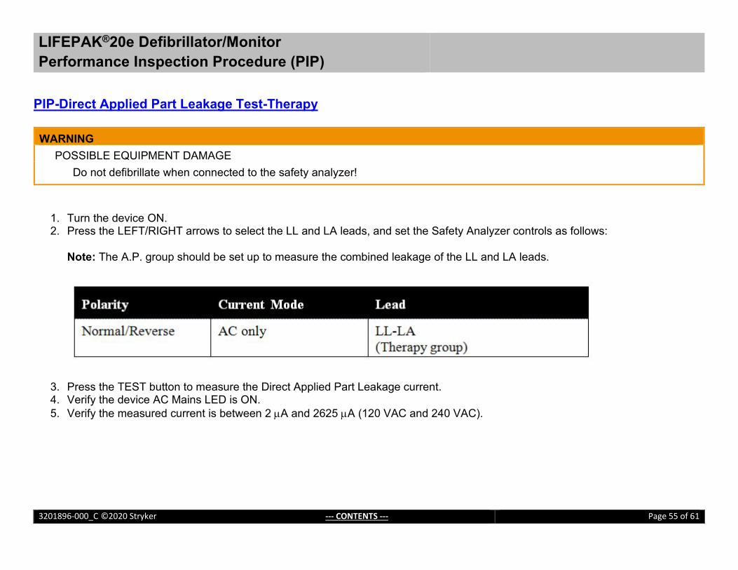
PIP-Direct Applied Part Leakage Test-Therapy WARNING POSSIBLE EQUIPMENT DAMAGE
Do not defibrillate when connected to the safety analyzer!
1. Turn the device ON. 2. Press the LEFT/RIGHT arrows to select the LL and LA leads, and set the Safety Analyzer controls as follows:
Note: The A.P. group should be set up to measure the combined leakage of the LL and LA leads.
3. Press the TEST button to measure the Direct Applied Part Leakage current. 4. Verify the device AC Mains LED is ON. 5. Verify the measured current is between 2 µA and 2625 µA (120 VAC and 240 VAC).

LIFEPAK®20e Defibrillator/Monitor Performance Inspection Procedure (PIP)
3201896-000_C ©2020 Stryker --- CONTENTS --- Page 56 of 61
PIP-Direct Applied Part Leakage Test-SPO2 Note: Execute this test if the LIFEPAK 20 is equipped with SpO2
WARNING POSSIBLE EQUIPMENT DAMAGE
Do not defibrillate when connected to the safety analyzer!
1. Turn the device ON. 2. Press the LEFT/RIGHT arrows to select the RL lead, and set the Safety Analyzer controls as follows:
3. Press the TEST button to measure the Direct Applied Part Leakage current. 4. Verify the device AC Mains LED is ON. 5. Verify the measured current is less than 2625 µA (120 VAC and 240 VAC).

LIFEPAK®20e Defibrillator/Monitor Performance Inspection Procedure (PIP)
3201896-000_C ©2020 Stryker --- CONTENTS --- Page 57 of 61
PIP-Safety Analyzer Setup - Earth Leakage Test
WARNING POSSIBLE EQUIPMENT DAMAGE
Do not defibrillate when connected to the safety analyzer!
To perform the Earth Leakage test in accordance with IEC 60601, set up the Safety Analyzer as follows:
1. Press the SETUP button on the Safety Analyzer. 2. Press the F4/MORE button. 3. Press the F2/INSTRUMENT button. 4. Press the F1/STANDARD button. 5. Press the UP/DOWN arrows to select the 60601 Standard. 6. Press the DONE button.

LIFEPAK®20e Defibrillator/Monitor Performance Inspection Procedure (PIP)
3201896-000_C ©2020 Stryker --- CONTENTS --- Page 58 of 61
PIP-Earth Leakage Test - Normal Condition (NC) WARNING POSSIBLE EQUIPMENT DAMAGE
Do not defibrillate when connected to the safety analyzer!
1. Turn the device ON. 2. Press the µA button on the Safety Analyzer. 3. Press the F1/EARTH button on the Safety Analyzer and set the Safety Analyzer controls as follows:
Note: Pause briefly between switching polarity to prevent damage to the defibrillator.
4. Verify the device AC Mains LED is ON. 5. Verify the measured current is between 15 µA and 2250 µA (120 VAC and 240 VAC).

LIFEPAK®20e Defibrillator/Monitor Performance Inspection Procedure (PIP)
3201896-000_C ©2020 Stryker --- CONTENTS --- Page 59 of 61
PIP-Earth Leakage Test - Single Fault Condition (SFC)
1. Turn the device ON. 2. Press the µA button on the Safety Analyzer. 3. Press the F1/EARTH button on the Safety Analyzer and set the Safety Analyzer controls as follows:
Note: Pause briefly between switching polarity to prevent damage to the defibrillator.
4. Verify the device AC Mains LED is ON. 5. Verify the measured current is between 15 µA and 2625 µA (120 VAC and 240 VAC).

LIFEPAK®20e Defibrillator/Monitor Performance Inspection Procedure (PIP)
3201896-000_C ©2020 Stryker --- CONTENTS --- Page 60 of 61
PIP-Restore Customer Settings
Restore customer settings...
1. Enter SETUP menu. 2. Choose MANUAL MODE. 3. Choose MANUAL ACCESS. 4. Choose CUSTOMER’S NORMAL SETTINGS.

3201896-000_C ©2019 Stryker Page 61 of 61
________________________________________________________________________________
LIFEPAK®20e Defibrillator/Monitor _____________________________________________________________________________ Performance Inspection Procedure (PIP) For further information, please call Stryker at 1.800.442.1142 or visit www.strykeremergencycare.com
Stryker 11811 Willows Road NE Redmond, WA 98073-9708 USA Tel: 425.867.4000 Fax: 425.458.1404 www.strykeremergencycare.com
Stryker Australia Pty Ltd 8 Herbert Street St Leonards NSW 2065 Australia
Physio-Control, Inc., 11811 Willows Road NE, Redmond, WA 98052 USA
Stryker European Operations B.V., Herikerbergweg 110, 1101 CM Amsterdam, The Netherlands
_______________________________________________________________________________________________________________________________________________________________________________________ © 2019 Stryker. Specifications are subject to change without notice.
Publication Date: 03/2019