Life Science Journal 2013;10(7s) ... · Investigation of Water Tank as TLD for Vibration Control of...
8
Life Science Journal 2013;10(7s) http://www.lifesciencesite.com 1182 Investigation of Water Tank as TLD for Vibration Control of Frame Structures under Seismic Excitations Syed Saqib Mehboob 1 , Qaiser uz Zaman Khan 2 , Fiaz Tahir 3 , Muhammad Jamil Ahmad 4 1.4. Postgraduate Scholar, Civil Engineering Department, UET Taxila, Pakistan 2. Professor, Civil Engineering Department, UET Taxila, Pakistan 3. Assistant Professor, Civil Engineering Department, UET Taxila, Pakistan [email protected] Abstract: In this research work, the numerical investigation was carried out using ANSYS/CivilFEM. Three multi- storey building models were selected after proper design of their structural elements. The water tank was installed at the top most floor level. Then to check response of building to earthquake, the Time-History data for ElCentro 1940 and Muzafrabad Kashmir 2005 earthquakes were applied. This was investigated to identify the vulnerable areas of the building for water tank. Provided it was located off the center of mass of building and for different water level conditions. For water levels above 0.5h the unsettled trend of reduction in peak response was noted. It is was also concluded that if the level of water in the tank is maintained between 0.32h to 0.81h (mass ratio 0.104 to 0.137) it may have the tendency to mitigate the vibrations of RC frame structures under seismic excitations. [Mehboob S S, Khan Q Z , Tahir F , Ahmad M J. Investigation of Water Tank as TLD for Vibration Control of Frame Structures under Seismic Excitations. Life Sci J 2013;10(7s):1182-1189] (ISSN:1097-8135). http://www.lifesciencesite.com . 188 Key words: Seismic excitation, TLD, Tuning, Vibration control, Monolithically, Center of mass. 1. Introduction Natural calamities fear the man kind since the day first. Earthquake is the most distressing hazard on the earth. An essential requirement of present-day in new trend structural design and assessment of existing structures is seismic hazard extenuation. Seismic ground motions are a major cause for creating damaging effects on Reinforced Concrete (RC) multi- storey buildings. So far, the exact characteristics of the shaking motion of ground at a particular site cannot be anticipated with certain precision. It is hard to evaluate all factors that strike the overall behavior of a complex structure when subjected to the seismic excitation. Over last few decades, the research and application of seismic engineering has advanced so rapidly. Complex computational modeling of RC structure for non-linear analysis had led engineers in the earlier period to rely greatly on empirical formulas which were derived from numerous experiments for the design of RC structures. The conventional approach to mitigate the seismic hazard is to design the structure itself so strong, sufficient to resist the earthquake forces. But it would be very costly to move it on for the under developing countries like Pakistan where the investments and budgets for civil projects are of great concern. So in this scenario even the alternate concepts of Tuned Mass Damper (TMD) devices either passive or active in function are not feasible. These are proven to be uneconomical to be implemented on buildings. Today, due to the development in the field of Finite Element Modeling (FEM), computer software packages are ready to aid the engineers to study the non-linear analysis of structures. On 8 th of October 2005, the land of Pakistan was jolted by a major earthquake and it led a huge destruction in many areas of country. The earthquake left many of the buildings severely damaged while many others were collapsed as well. One of the main residential buildings, named Margalla Tower, in the territory of Pakistan’s capital was collapsed. Unlikely Pakistan having none of its own proper guidelines for construction design and detailing, codes from the developed countries are in practice. After October 8, 2005 earthquake the Government of Pakistan reprocessed the zoning of country and set up Building Code of Pakistan 2007 based on Uniform Building Code 1997. As the capital of Pakistan and coastal area of Sindh Province sits on major fault lines and almost all other major cities of Pakistan comes in seismic zone of severe category, after the revised zone map of Pakistan [1]. Hence the trouble demanding the revision of code is evident for the engineers, exploring the seismic mitigation techniques. It is now well practicable to analyze the RC frame structures using the approach of Finite Element Modeling. In this study an assessment of seismic behavior has been made to understand the possible vibration response of building with the provision of water tank properly located and tuned. The program used in this study, ANSYS/CivilFEM general purpose finite element computer package, is a well-known, multi-purpose finite element program. The CivilFEM
Transcript of Life Science Journal 2013;10(7s) ... · Investigation of Water Tank as TLD for Vibration Control of...
Life Science Journal 2013;10(7s) http://www.lifesciencesite.com
1182
Investigation of Water Tank as TLD for Vibration Control of Frame Structures under Seismic Excitations
Syed Saqib Mehboob1, Qaiser uz Zaman Khan2, Fiaz Tahir3, Muhammad Jamil Ahmad4
1.4. Postgraduate Scholar, Civil Engineering Department, UET Taxila, Pakistan
2. Professor, Civil Engineering Department, UET Taxila, Pakistan 3. Assistant Professor, Civil Engineering Department, UET Taxila, Pakistan
[email protected] Abstract: In this research work, the numerical investigation was carried out using ANSYS/CivilFEM. Three multi-storey building models were selected after proper design of their structural elements. The water tank was installed at the top most floor level. Then to check response of building to earthquake, the Time-History data for ElCentro 1940 and Muzafrabad Kashmir 2005 earthquakes were applied. This was investigated to identify the vulnerable areas of the building for water tank. Provided it was located off the center of mass of building and for different water level conditions. For water levels above 0.5h the unsettled trend of reduction in peak response was noted. It is was also concluded that if the level of water in the tank is maintained between 0.32h to 0.81h (mass ratio 0.104 to 0.137) it may have the tendency to mitigate the vibrations of RC frame structures under seismic excitations. [Mehboob S S, Khan Q Z , Tahir F , Ahmad M J. Investigation of Water Tank as TLD for Vibration Control of Frame Structures under Seismic Excitations. Life Sci J 2013;10(7s):1182-1189] (ISSN:1097-8135). http://www.lifesciencesite.com. 188 Key words: Seismic excitation, TLD, Tuning, Vibration control, Monolithically, Center of mass.
1. Introduction
Natural calamities fear the man kind since the day first. Earthquake is the most distressing hazard on the earth. An essential requirement of present-day in new trend structural design and assessment of existing structures is seismic hazard extenuation. Seismic ground motions are a major cause for creating damaging effects on Reinforced Concrete (RC) multi-storey buildings. So far, the exact characteristics of the shaking motion of ground at a particular site cannot be anticipated with certain precision. It is hard to evaluate all factors that strike the overall behavior of a complex structure when subjected to the seismic excitation.
Over last few decades, the research and application of seismic engineering has advanced so rapidly. Complex computational modeling of RC structure for non-linear analysis had led engineers in the earlier period to rely greatly on empirical formulas which were derived from numerous experiments for the design of RC structures. The conventional approach to mitigate the seismic hazard is to design the structure itself so strong, sufficient to resist the earthquake forces. But it would be very costly to move it on for the under developing countries like Pakistan where the investments and budgets for civil projects are of great concern. So in this scenario even the alternate concepts of Tuned Mass Damper (TMD) devices either passive or active in function are not feasible. These are proven to be uneconomical to be implemented on buildings. Today, due to the development in the field of Finite Element Modeling (FEM), computer software packages are ready to aid
the engineers to study the non-linear analysis of structures.
On 8th of October 2005, the land of Pakistan was jolted by a major earthquake and it led a huge destruction in many areas of country. The earthquake left many of the buildings severely damaged while many others were collapsed as well. One of the main residential buildings, named Margalla Tower, in the territory of Pakistan’s capital was collapsed. Unlikely Pakistan having none of its own proper guidelines for construction design and detailing, codes from the developed countries are in practice. After October 8, 2005 earthquake the Government of Pakistan reprocessed the zoning of country and set up Building Code of Pakistan 2007 based on Uniform Building Code 1997.
As the capital of Pakistan and coastal area of Sindh Province sits on major fault lines and almost all other major cities of Pakistan comes in seismic zone of severe category, after the revised zone map of Pakistan [1]. Hence the trouble demanding the revision of code is evident for the engineers, exploring the seismic mitigation techniques.
It is now well practicable to analyze the RC frame structures using the approach of Finite Element Modeling. In this study an assessment of seismic behavior has been made to understand the possible vibration response of building with the provision of water tank properly located and tuned. The program used in this study, ANSYS/CivilFEM general purpose finite element computer package, is a well-known, multi-purpose finite element program. The CivilFEM

Life Science Journal 2013;10(7s) http://www.lifesciencesite.com
1183
module is specific tool for modeling of civil structures like RC frame structures etc. ANSYS/CivilFEM can perform several types of dynamic analyses, including modal, transient, harmonic and spectrum analyses. In this study, Transient Analysis (Time History Analysis) is selected, based on the objective of the project. In this study earthquake data for ElCentro 1940 and Muzafrabad Kashmir 2005 has been used for analysis. 2. Literature Review
Till date many researchers have made different innovative and fruitful studies upon buildings with TLD to stand firm against wind and earthquake forces. Studies carried out by G. Hemalatha and K.P. Jaya 2008 [2], focused on the feasibility of providing passive TMD on building when subjected to earthquake. The researchers had only varied water at five different levels for analysis. Though they had used ANSYS for computational analysis but considered only three basic properties for modeling of structure (i.e., density, young’s modulus & poison’s ratio).
Kim Young-Moon et al. 2006 [3], conducted shaking table experiments to investigate the characteristics of water sloshing motion in TLD and Tuned Liquid Column Damper (TLCD).
Gardarsson S. et al. 2001 [4], explored the idea of TLD having the base with sloped bottom. Experimental results for TLD with slopped base and TLD with normal flat base were compared.
Soong & Dargush et al. 1997 [5], presented a thorough assessment of liquid dampers. Tamura et al. 1995 [6], had installed the liquid dampers on Tokyo International Airport to check effectiveness of dampers. Luckily they had found that there was an increase of reduction (i.e., 7.6% from 1.0%).
Sun and Fujino et al.1995 [7], extended their previous work on tuned liquid dampers and studied the properties of tuned liquid dampers using a TMD analogy.
Sun et al.1992 [8], built up a numerical model for TLD. The shallow water wave theory was the base of that numerical model.
Fujii, et al. 1990 [9], had investigated the structural vibrations induced by wind. They had installed the sloshing dampers at Nagasaki Airport Tower (altitude 42 m) and Yokohama Marine Tower (altitude 101 m). It was observed that wind generated vibrations reduced to one half after installation of damper.
Modi and Welt 1988 [10], intimated the use of TLD in buildings. And due to geometrical resemblance they referred this methodology to Nutation Dampers.
Bauer 1984 [11], worked on rectangular TLD filled with two immiscible liquids and observed the reduction of peak response against lateral excitations.
Moreover, an effort is made to specify suitable design parameters for TLD establishment that would be efficient in operation of structural response against structural vibration. The parameters considered are tuning ratio, mass ratio, and depth ratio etc. As yet, numerous studies have been made on implementation of TLD for vibration control of multi-storey buildings. Nearly all of the researchers had assumed the structural model either as a single degree of freedom (SDOF) model or one dimensional multi degree of freedom (MDOF) model. To the best of my knowledge:
i. No researcher has considered the structural model as 3D-MDOF system for investigation of optimum location of water tank using FEM based computer software.
ii. Likewise, a very few work have been done on 3D-MDOF system for optimizing the range of water level in the tank using FEM based computer software.
iii. Against wind vortex reasonable research is available. Same here, using FEM based computer software, very less work has been conducted for seismic excitations for application of TLD to control vibration of structures.
Therefore, these three unexplored areas has become my aim of study. 3. Methodology
The scope of this study includes investigating vibrational response of a 3D model of building provided with a water tank on the top roof level. Study was carried out for water tank acting as a TLD, using ANSYS/CivilFEM. Two random ground acceleration cases corresponding to past earthquake time-histories were applied to the model buildings. RC Building Model
Frame structures of varying heights are considered for the present study shown in Fig. 1, whereas Table 1 shows their detail.
The material properties for different elements
used in the analysis are summarized in Table 2. The flexural members, both beams and
columns were modeled using element Beam189 and floor slabs were modeled using element Shell181. To set up the non-linear response of structure the stress-strain curves used for concrete members were proven possible with the use of CivilFEM. But the soil
Life Science Journal 2013;10(7s) http://www.lifesciencesite.com
1184
properties and effects of soil structure interaction were ignored in this research. Hence the translational ground motion was applied in the spatial co-ordinate direction directly to the base of all three models.
(a) Two Stoy (b) Five Storey ` (c) Seven Storey Figure 1. ANSYS/CivilFEM models of RC Structures
Table 2. Material Properties Concrete
Density 2500 kg/m3 Young’s Modulus 3.1246e+010 Pa Poisson’s Ratio 0.2
Reinforcement Bars Density 7850 kg/m3
Young’s Modulus 2e+011 Pa Poisson’s Ratio 0.3
Optimization Proper tuning is required for water tank so to
be acted as TLD. Improper tuning in respect of its location and water level condition may exaggerate the vibrational response of building instead of providing reductive effect. The horizontal input ground motions, in the form of acceleration time-history are summarized in the Table 3.
Table 3. Time History Record Summary
Country/Record Station/
Year Magnitude
PGA (g)
California/Imperial Valley (E1)
ElCentro (1940)
6.9 0.32
Pakistan/Muzafrabad Kashmir (MK)
Abottabad (2005)
7.6 0.23
Thus, for each earthquake data the
displacement vs. time-history patterns were observed and recorded. Then the parameters were studied by considering the change in displacement as a measure of reducing in vibration. Water Tank as TLD
Since the water storage tanks are built-in component of buildings and mostly these are constructed on the top roof level, hence they add dead burden (in addition to expected design load) on the structure. During earthquakes, this extra mass can be employed as damper to take over the surplus energy transmitted to the structure.
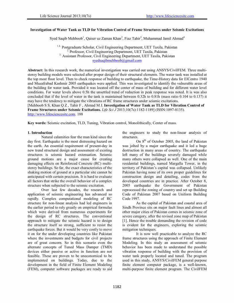
In plan, the water tank had dimension of 3 x 3 m for all three models and with 2 m elevated length for M2, M5 & M7 and was positioned on the top floor level. In the models, walls and roof of the tank both were of concrete. Shell181 was used for walls and roof slab while Fluid80 element was used to define water, shown in Fig. 2. Figure 2. Water tank located at center and ANSYS/ CivilFEM elements
Shell181
Fluid80
Life Science Journal 2013;10(7s) http://www.lifesciencesite.com
1185
The properties of water used for analysis are mentioned in Table 4.
Table 4. Properties of Water
MATERIAL PROPERTY Water
Density 1000 kg/m3 Bulk Modulus 2.068e9 Pascal Viscosity 1.13e-3 N.S/m2 Sonic velocity 1483 m/s
4. Analysis Results Response of structure for different locations of water tank
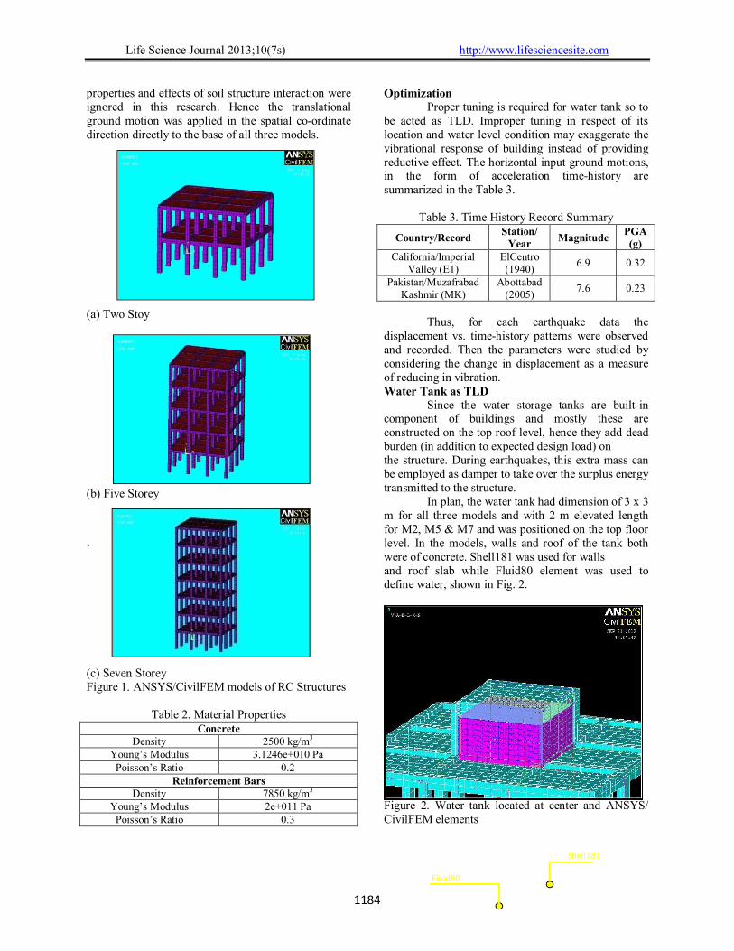
The location of water tank was changed (namely at center, side & corner) and for each case of tank location, all three models were investigated for E1 and MK earthquake data. The extreme recorded values of roof displacement are plotted in the form of histogram and shown in Fig. 4 and Fig. 5.
Figure 4. Maximum roof displacements for half filled tank condition for (E1)
Figure 5. Maximum roof displacements for half filled tank condition for (MK)
From the results thus obtained and shown in Fig. 4 & Fig. 5, it is revealed that the most suitable location for the water tank may be the center of building. In a general way it is observed that for certain condition when center of mass of water tank coincides with center of mass of building, is the most suitable location for construction of water tank.
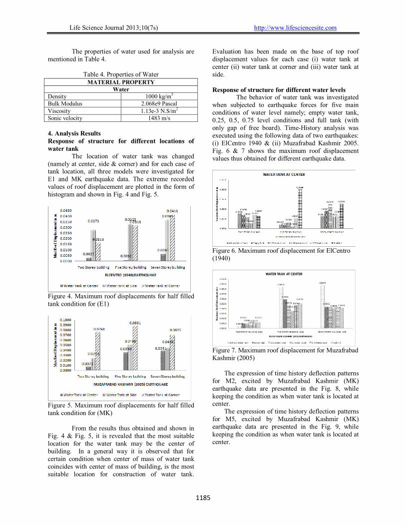
Evaluation has been made on the base of top roof displacement values for each case (i) water tank at center (ii) water tank at corner and (iii) water tank at side. Response of structure for different water levels
The behavior of water tank was investigated when subjected to earthquake forces for five main conditions of water level namely; empty water tank, 0.25, 0.5, 0.75 level conditions and full tank (with only gap of free board). Time-History analysis was executed using the following data of two earthquakes: (i) ElCentro 1940 & (ii) Muzafrabad Kashmir 2005. Fig. 6 & 7 shows the maximum roof displacement values thus obtained for different earthquake data.
Figure 6. Maximum roof displacement for ElCentro (1940)
Figure 7. Maximum roof displacement for Muzafrabad Kashmir (2005)
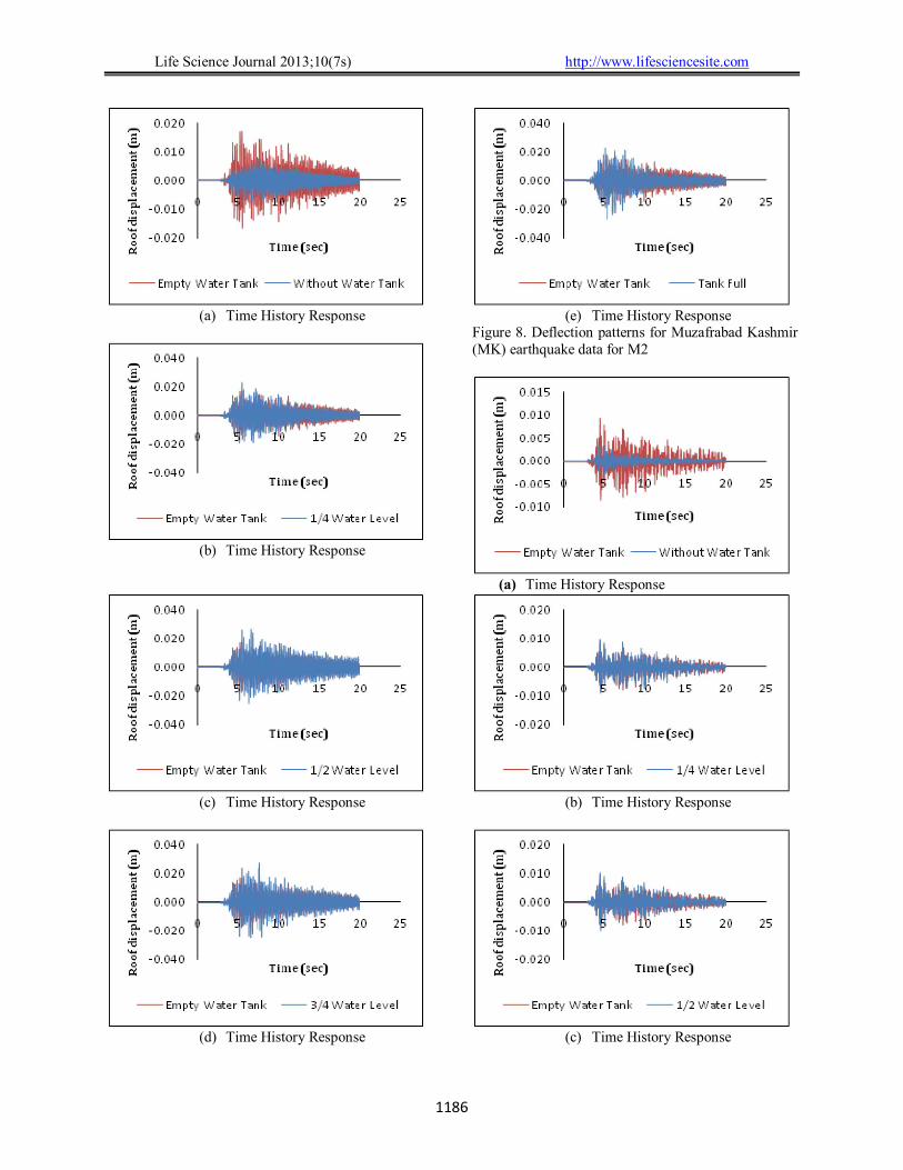
The expression of time history deflection patterns for M2, excited by Muzafrabad Kashmir (MK) earthquake data are presented in the Fig. 8, while keeping the condition as when water tank is located at center.
The expression of time history deflection patterns for M5, excited by Muzafrabad Kashmir (MK) earthquake data are presented in the Fig. 9, while keeping the condition as when water tank is located at center.
Life Science Journal 2013;10(7s) http://www.lifesciencesite.com
1186
(a) Time History Response
(b) Time History Response
(c) Time History Response
(d) Time History Response
(e) Time History Response
Figure 8. Deflection patterns for Muzafrabad Kashmir (MK) earthquake data for M2
(a) Time History Response
(b) Time History Response
(c) Time History Response

Life Science Journal 2013;10(7s) http://www.lifesciencesite.com
1187
(d) Time History Response
(e) Time History Response
Figure 9. Deflection patterns for Muzafrabad Kashmir (MK) earthquake data for M5.
The expression of time history deflection patterns for M7, excited by Muzafrabad Kashmir (MK) earthquake data are presented in the Fig. 10, while keeping the condition as when water tank is located at center.
(a) Time History Response
(b) Time History Response
(c) Time History Response
(d) Time History Response
(e) Time History Response
Figure 10. Deflection patterns for Muzafrabad Kashmir (MK) earthquake data for M7.
Life Science Journal 2013;10(7s) http://www.lifesciencesite.com
1188
5. Results & Discussion Two Storey Model
The following points were observed from the time history response patterns shown in Fig. 8 and from histograms shown in Fig. 6 & 7 as:
i. For ElCentro earthquake data, the highest reduction in response in term of displacement value is 60.3% when tank 0.5 filled and min. reduction is 5.88 % for full tank condition.
ii. For MK data, maximum reduction in peak response is 27.7% for half level condition. The quarter fill condition also showed reduction in vibrational response.
From results it is found that 0.5-level condition of water shows coherency in results for two histories of earthquake data. It is observed that empty water tank might be safe but the minimum water level (i.e., 0.25h) should be maintained. Five Storey Model
The following points were observed from the time history response patterns shown in Fig. 9 and from histograms shown in Fig. 6 & 7 as:
i. For 0.25h condition of water level, the reduction in peak response is 41.1% for E1 data.
ii. For MK data, the peak reduction is almost equal (≈ 49.14%) for all tank conditions.
Seven Storey Model
The following points were observed from the time history response patterns shown in Fig. 10 and from histograms shown in Fig. 6 & 7 as:
i. For ElCentro earthquake data, the highest reduction in vibrational response is observed for 0.5-level condition. And the time vs. displacement response pattern is satisfactory for 0.5-level conditions.
ii. Reduction in peak response is around 9.25 % for 0.25 to full water condition, for MK data.
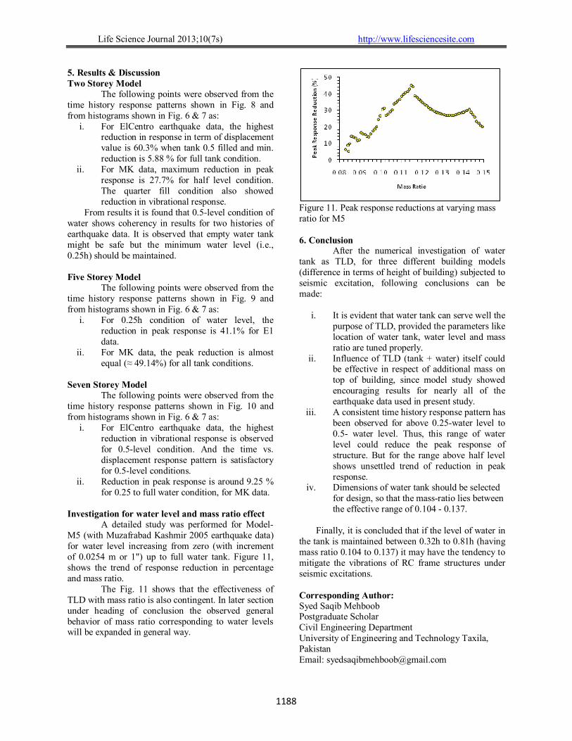
Investigation for water level and mass ratio effect
A detailed study was performed for Model-M5 (with Muzafrabad Kashmir 2005 earthquake data) for water level increasing from zero (with increment of 0.0254 m or 1") up to full water tank. Figure 11, shows the trend of response reduction in percentage and mass ratio.
The Fig. 11 shows that the effectiveness of TLD with mass ratio is also contingent. In later section under heading of conclusion the observed general behavior of mass ratio corresponding to water levels will be expanded in general way.
Figure 11. Peak response reductions at varying mass ratio for M5 6. Conclusion
After the numerical investigation of water tank as TLD, for three different building models (difference in terms of height of building) subjected to seismic excitation, following conclusions can be made:
i. It is evident that water tank can serve well the
purpose of TLD, provided the parameters like location of water tank, water level and mass ratio are tuned properly.
ii. Influence of TLD (tank + water) itself could be effective in respect of additional mass on top of building, since model study showed encouraging results for nearly all of the earthquake data used in present study.
iii. A consistent time history response pattern has been observed for above 0.25-water level to 0.5- water level. Thus, this range of water level could reduce the peak response of structure. But for the range above half level shows unsettled trend of reduction in peak response.
iv. Dimensions of water tank should be selected for design, so that the mass-ratio lies between the effective range of 0.104 - 0.137.
Finally, it is concluded that if the level of water in
the tank is maintained between 0.32h to 0.81h (having mass ratio 0.104 to 0.137) it may have the tendency to mitigate the vibrations of RC frame structures under seismic excitations. Corresponding Author: Syed Saqib Mehboob Postgraduate Scholar Civil Engineering Department University of Engineering and Technology Taxila, Pakistan Email: [email protected]
Life Science Journal 2013;10(7s) http://www.lifesciencesite.com
1189
References [1] Building Code of Pakistan 2007. [2] G. Hemalatha and K.P. Jaya., “Water Tank as
Passive TMD for Seismically Excited Structures”, Asian journal of civil engineering (building and housing), Vol. 9, No. 4, 2008, 349-366.
[3] Kim Young-Moon, You Ki-Pyo, Cho Ji-Eun, and Hong Dong-Pyo., “The Vibration Performance Experiment of Tuned Liquid Damper and Tuned Liquid Column Damper”, Journal of Mechanical Science and Technology, Vol. 20, No. 6, 2006, 795-805.
[4] Gardarsson S., Yeh H., and Reed D., “Behavior of Sloped-Bottom Tuned Liquid Dampers”, Journal of Engineering Mechanics, Vol. 127, No. 3, 2001, 266-271.
[5] Soong T. T., Dargush., Gary F., “Passive Energy Dissipation Systems in Structural Engineering”, John Wiley & Sons, Ltd. (UK), 1997.
[6] Tamura Y., Fujii K., Ohtsuki T., Wakahara T., and Kohsaka R., “Effectiveness of tuned liquid dampers
under wind excitation”, Engineering Structures, Vol. 17, No. 9, 1995, 609-621.
[7] Sun, L.M., Fujino, Y., Chaiseri, P., Pacheco, B.M., “Properties of tuned liquid dampers using a TMD analogy”, Earthquake Engineering and Structural Dynamics, Vol. 24, No. 7, 1995, 967-976.
[8] Sun L.M., Fujino Y., Pacheco B.M., and Chaiseri P., “Modeling of Tuned Liquid Damper (TLD)”, Journal of Wind Engineering and Industrial Aerodynamics, 41- 44, 1992, 1883-1894.
[9] Fujii K., Tamura Y., Sato T., Wakahara T., “Wind-induced vibration of tower and practical applications of Tuned Sloshing Damper”, Journal of Wind Engineering and Industrial Aerodynamics, 33, 1990, 263-272.
[10] Modi V.J., and Welt F., “Damping of wind induced oscillations through liquid sloshing”, Journal of Wind Engineering and Industrial Aerodynamics, 30, 1988, 85-94.
[11] Bauer H.F., “Oscillations of immiscible liquids in a rectangular container: A new damper for excited structures”, Journal of Sound and Vibration, 93(1), 1984, 117-133.
7/10/2013