Life Science Journal, 2012;9(1) ...control rats was significantly higher (p

Life Science Journal 2012;9(3) http://www.lifesciencesite.com
1904
Design of an optimized Reversible Ternary and Binary Bidirectional and Normalization Barrel Shifters for Floating Point Arithmetic
Nayereh Hosseini Nia
Department of Computer Engineering, Tabriz Branch, Islamic Azad University, Tabriz, Iran
Abstract: One of the most challenging issues in circuit design is power consumption. Designing circuit using reversible logic is one of the solutions to decrease power loss. Theoretically, a reversible circuit has zero internal power dissipation because it does not lose information. Thus reversibility will be necessary for future circuit designs. Multiple-valued reversible logic which decreases the width of quantum circuits is an emerging area of reversible/quantum logic. The simplest type of multiple-valued logic is ternary quantum logic. On the other hand, Data shifting has been widely used in many key computer processes such as high-speed/low-power error-control application, address decoding, bit indexing and many arithmetic operations specially floating point arithmetic units. Barrel shifters are combinatorial shifters which are used in high speed and high performance applications. Reversible binary and ternary bidirectional barrel shifter and binary normalization barrel shifters for floating point arithmetic are presented in this paper for the first time. Proposed barrel shifters are evaluated and formulated in terms of number of reversible gates, number of garbage outputs, number of constant inputs, quantum cost and hardware complexity. All the scales are in nanometric area. [Nayereh Hosseini Nia. Design of an optimized Reversible Ternary and Binary Bidirectional and Normalization Barrel Shifters for Floating Point Arithmetic. Life Sci J 2012;9(3):1904-1915] (ISSN:1097-8135). http://www.lifesciencesite.com. 276 Key words: nanotechnology based systems; quantum computing; reversible logic; reversible multiple-valued logic; ternary quantum logic; reversible ternary barrel shifters. 1. Introduction
Although traditional computers with the advent of VLSI and ULSI technologies are constructed in smaller dimensions and high processing speed, but always there is a question that up to where they can continue in such a direction. Due to the fact that there is a constraint for traditional computers’ dimensions and processing speed, it cannot be continued any more. Thus in such a case novel technologies based on nanotechnology such as Quantum Computing will be replaced with the traditional ones. Quantum computers are based on Quantum physics’ laws and have been constructed on reversible gates design and using hardware concludes Quantum tools, are suitable substitute for classic computers in the near future. In other words, nowadays, quantum computing and reversible circuits, in order to power minimization designs, have received significant attention. Bit loss from information relates to heat generation whereas in reversible circuits due to this fact that there is no any information loss, no heat will be generated. From one point of view Circuit design using reversible gates relates to no energy consumption in circuits. Landaulet[1] proved that generated heat for erasure of a single bit is KTln2 joules of energy Where K= 1.3806505*10-23m2 kg-2 K-1 (joule/Kelvin) is Boltzmann constant and T is the absolute temperature of the environment. In 1973 Bennett [2] pointed out
that reversible computing is computing without any information loss. Reversible logic is one of the interested subjects in systems based on nanotechnology, Quantum computing, low power CMOS design, DNA computing, bioinformatics and optical information processing. Multiple-valued quantum circuits are important options for future quantum computing and they have several advantages more than the corresponding binary quantum system. Muthukrishnan and Stroud showed realization of multiple-valued quantum gates using liquid ion-traps and proposed a family of 2-qudit multiple-valued gates called M-S gate[3]. The implementation of Ternary logic gate is realized by M-S gate. Moreover, ternary quantum gates have been realized using traps ions by Klimov et al [4], Hugh and Twamley [5]. Ternary reversible/quantum logic synthesis is a neoteric and growing area. There is a good number of works that have been presented on ternary quantum logic synthesis [6-18]. The quantum gates act on quantum bits (qubit). A qubit is a unit of quantum information. In ternary logic the possible states for a
qubit are 2&1,0 . On the other hand, circuit
design for shifting data is possible as combinatorial and sequential circuits. Shift registers are sequential circuits which require clock pulse for shifting data while barrel shifters are combinatorial circuits without any requirement clock pulse.
Life Science Journal 2012;9(3) http://www.lifesciencesite.com
1905
As we know, the most popular numerical system that is commonly used in computer systems and has peculiar importance in its widespread use in various areas is “floating point” numbers. In floating point operations such as addition/subtraction, multiplication and division, shifters are key components and crucial in computing speed. The speed of shifters has an extreme impact on overall performance of the floating-point addition/subtraction unit. Consequently, shifters are usually implemented as combinatorial shifters rather than shift registers, which would require a large and variable number of clock cycles to complete the shift. Barrel shifters are a common design choice due to fulfilling multi-bit shifts in a single cycle. Barrel shifters are normally utilized in many applications as: word pack/unpack, encryption and decryption Algorithms, test generation for DSP [19], variable length encoding, floating-point normalization, quantum-dot cellular automata [20], high-speed/low-power error-control application [21] and many other applications. To design a reversible ternary and binary floating point adder/subtractor is required to have crucial ternary/binary barrel shifters, so in this paper, optimized reversible binary and ternary bidirectional barrel shifters and also normalization barrel shifters for floating point arithmetic are presented for the first time. The proposed work is the first endeavor for designing reversible binary and ternary non-rotating barrel shifters.
The structure of the paper is organized as follows: section 2 discusses the common definitions of reversible and ternary logic and some utilized ternary gates. Section 3 presents a summary of the works that have been performed on reversible binary and ternary barrel shifters. Introductory structure on barrel shifters as well as Reversible binary and ternary bidirectional logarithmic logical shifter is described in section 4. Required reversible barrel
shifters for floating point arithmetic are proposed in section 4 too. The simulation results with VHDL language and Quartus simulator are shown in section 5 and section 6 draws conclusions. 2. Reversible Binary and Ternary Gates
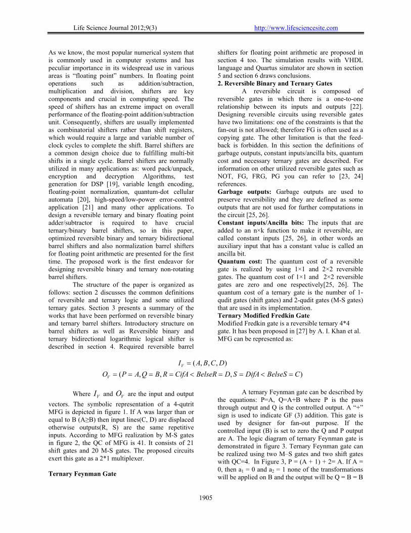
A reversible circuit is composed of reversible gates in which there is a one-to-one relationship between its inputs and outputs [22]. Designing reversible circuits using reversible gates have two limitations: one of the constraints is that the fan-out is not allowed; therefore FG is often used as a copying gate. The other limitation is that the feed-back is forbidden. In this section the definitions of garbage outputs, constant inputs/ancilla bits, quantum cost and necessary ternary gates are described. For information on other utilized reversible gates such as NOT, FG, FRG, PG you can refer to [23, 24] references. Garbage outputs: Garbage outputs are used to preserve reversibility and they are defined as some outputs that are not used for further computations in the circuit [25, 26]. Constant inputs/Ancilla bits: The inputs that are added to an n×k function to make it reversible, are called constant inputs [25, 26], in other words an auxiliary input that has a constant value is called an ancilla bit. Quantum cost: The quantum cost of a reversible gate is realized by using 1×1 and 2×2 reversible gates. The quantum cost of 1×1 and 2×2 reversible gates are zero and one respectively[25, 26]. The quantum cost of a ternary gate is the number of 1-qudit gates (shift gates) and 2-qudit gates (M-S gates) that are used in its implementation. Ternary Modified Fredkin Gate Modified Fredkin gate is a reversible ternary 4*4 gate. It has been proposed in [27] by A. I. Khan et al. MFG can be represented as:
),,,(
),,,(
CBelseSDifASDBelseRCifARBQAPO
DCBAI
V
V
Where VI and VO are the input and output
vectors. The symbolic representation of a 4-qutrit MFG is depicted in figure 1. If A was larger than or equal to B (A≥B) then input lines(C, D) are displaced otherwise outputs(R, S) are the same repetitive inputs. According to MFG realization by M-S gates in figure 2, the QC of MFG is 41. It consists of 21 shift gates and 20 M-S gates. The proposed circuits exert this gate as a 2*1 multiplexer. Ternary Feynman Gate
A ternary Feynman gate can be described by the equations: P=A, Q=A+B where P is the pass through output and Q is the controlled output. A “+” sign is used to indicate GF (3) addition. This gate is used by designer for fan-out purpose. If the controlled input (B) is set to zero the Q and P output are A. The logic diagram of ternary Feynman gate is demonstrated in figure 3. Ternary Feynman gate can be realized using two M–S gates and two shift gates with QC=4. In Figure 3, P = (A + 1) + 2= A. If A = 0, then a1 = 0 and a2 = 1 none of the transformations will be applied on B and the output will be Q = B = B
Life Science Journal 2012;9(3) http://www.lifesciencesite.com
1906
+ 0 = A + B. If A = 1, then a1 = 1 and a2 = 2 only the right transformation (+1) will be applied on B and the output will be Q = B + 1 = A + B. If A = 2, then a1 = 2 and a2 =0 the left transformation (+2) will be applied on B and the output will be Q = B + 2 = A + B [27].
Figure 1. Symbol of Ternary MFG
Figure 2. Modified Fredkin Gate Realization Using M-S gate
BAQ
(a) (b) Figure 3. Ternary Feynman gate, (a): Symbol of Ternary FG, (b): Realization of ternary FG using M-S gate
Ternary Toffoli Gate
Three-qutrit Ternary Toffoli gate has three inputs. A and B are the controlling input and C is the controlled one. TTG can be represented as:
),,(
),,(
CABRBQAPO
CBAI
V
V
Where VI and VO are the input and output
vectors. The symbolic representation of a 3-qutrit TTG and quantum realization of this gate by M-S
gates are depicted in figure 4. As can be observed the realization of TTG required two ternary Feynman gates and four 1*1 shift gates and four 2*2 M-S gates. So it will have a total of eight 1*1 shift gates and eight 2*2 M-S gates, thus the quantum cost of TTG equals 16 with no ancillary bit [27].
(a) (b)
Figure 4: Ternary Toffoli gate, (a): Symbol of Ternary TG, (b): Realization of ternary TG using M-S gate 3. Literature Survey
Barrel shifters are useful in embedded processors. Multiple shifts are needed to do computations in digital signal processors. Paul Gigliotti [28] proposed the design of irreversible barrel shifters using multipliers. Several other complex irreversible barrel shifters such as Mask-based data-reversal barrel shifter, Mask-based two’s complement barrel shifter and Mask-based one’s complement barrel shifter with overflow and zero
flag have also been presented by Pillmeier and et al. [29]. Saeid Gorgin and Amir Kaivani[30] published the first paper on reversible barrel shifters. They proposed a unidirectional logarithmic shifter with large namber of gates. Irina Hashmi and Hafiz Hasan Babu [31] showed the optimization of the Gorgin’s paper. They proposed an efficient unidirectional barrel shifter with less QC, garbage outputs and number of gates. Saurabh Kotiyal and et al. [32] described design of a ternary unidirectional barrel

Life Science Journal 2012;9(3) http://www.lifesciencesite.com
1907
shifter using multiple-valued reversible logic. There are several types of shift operations depending on their applications including logic shift, arithmetic shift and rotate. The proposed barrel shifters in [30-32] are capable of only rotating to the left. Thus, Ravish Aradhya H.V and et al [33] proposed bidirectional logarithmic shifter using RLM gate. The proposed barrel shifter in [33] can be rotate input data in both directions (left and right). Design of a reversible bidirectional barrel shifter is explained by Saurbh Kotiya, Himanshu Thapliyal and Nagarajan Ranganathan[34]. This barrel shifter is a non-rotating barrel shifter that is capable of bidirectional logic and arithmetic shift.
4. Barrel Shifter
Intel was the first company that utilized barrel shifters in its numerical data processors. A
combinatorial shifter generates all possible shifted patterns but only one is provided at the output according to some control bits. Since, in general, such combinatorial shifters are capable of performing circular shifts (rotates) as well, they are commonly known as barrel shifters [35]. In [30-33] left rotating and bidirectional rotating barrel shifters has been proposed, but non-rotating barrel shifters are required for floating point operations and many other applications. On the other hand, A barrel shifter can be implemented as a single level array where each input bit is directly connected to m (and even more) output lines. For example a single level array right shift barrel shifter with four bits input data and two select lines for controlling bit shift operation is depicted in figure 5.
Figure 5. Irreversible single level array four bit right barrel shifter
For floating point calculation, which deals
with large numbers, single level array barrel shifter design is not appropriate, because the large number of connections and resulting large electrical load make an undesirable solution [36]. One alternative is a logarithmic barrel shifter as demonstrated in figure 6. A logarithmic (m, K) barrel shifter is composed of m-bit input data and K select lines that control bit shift operations. The logarithmic barrel shifter has
nK 2log stages so that i=0, 1, …, (K‒1). In every
stage if di control signal equals one then 2i times shift will occur in input data, otherwise the input data will not change. The irreversible logarithmic shifter implemented with 2×1 multiplexers. The proposed reversible barrel shifters will be explained and evaluated in the next section.
Figure 6. (m, k) logarithmic barrel shifter

Life Science Journal 2012;9(3) http://www.lifesciencesite.com
1908
4.1 Proposed optimized Reversible bidirectional logarithmic logical shifter
A bidirectional logarithmic logical shifter is a non-rotating barrel shifter which can shift input data to left or right. It has a control signal (D) for determining the direction of the shift. If D signal is set to zero then the logical shifter will work as a logical right shifter otherwise it will work as a logical left shifter. For instance a 4-bit bidirectional logarithmic logical shifter which is shown in figure 7a has two stages(di, i=0,1) and it is constructed by 12 Fredkin gates, and every one of them is as a 2×1 multiplexer and 5 Feynman gates as a copying gate. The 2 Fredkin gates before and after the logical right shifter is required to reverse input data and logical right shifter’s output data respectively. The (4, 2) bidirectional logical barrel shifter which is depicted in figure 7 takes m3,m2,m1,m0 as data inputs and d1,d0 as select inputs. The circuit function is according to table 1. In D,d1,d0=000 & D,d1,d0=100 states the input data does not change, in other states the value in d1,d0 determines shift amount and depend on D the input data is shifted to the right or left.
Table 1. Function table of the (4, 2) bidirectional logical barrel shifter
D d1 d0 output
0 0 0 m3m2m1m0
0 0 1 0m3m2m1
0 1 0 00m3m2
0 1 1 000m3
1 0 0 m3m2m1m0
1 0 1 m2m1m00
1 1 0 m1m000
1 1 1 m0000
This article proposes an optimized
bidirectional logarithmic logical shifter. We can replace the FRG gates which have a zero input (figure 7a) with PG gates that are put as AND gates with two inputs consisting of data bit and
id . So the
proposed circuit has a less QC and hardware complexity than common bidirectional logical barrel shifter. Table 2 shows the compressive between the proposed design and common design.
Table 2. Comparison between common and optimized barrel shifter
Total Logical Calculation
Quantum Cost
NO. of Garbage outputs
NO. of Constant inputs
NO. of gates
183929 62 11 8 17 Optimized Design
Figure 7b
244829 65 11 8 17 Common Design
Figure 7a
(a) (b)
Figure 7. Bidirectional logarithmic logical shifter (a): Common design, (b): proposed optimized design
Optimized (4, 2) bidirectional logarithmic logical shifter has four main outputs and 11 garbage outputs with QC=62. Optimized (4, 2) bidirectional
logical barrel shifter can be generalized for (m, k) reversible barrel shifter.
Life Science Journal 2012;9(3) http://www.lifesciencesite.com
1909
Theorem 1: The proposed optimized (m, k) reversible bidirectional logical shifter has an m-bit input and output data and K stages for logical right shifter. Let NPG, NFRG and NFG be the total number of Peres, Fredkin and Feynman gates respectively then
12 KPGN
)12()1( KFRG mKN
1
0
)2(K
i
iFG mN
Proof: PG is utilized as a AND gate in proposed circuit. Every stage in logical right shifter is denoted by i, so the number required PG gates in each stage
equals 1,...,1,0,2 kii thus K stages will have a
total of
1
02
k
i
i Peres gates. Every reversal data unit
needs 2
n Fredkin gates and the logical right shifter
requires (m‒2i) Fredkin gates for each stage. Thus an m-bit bidirectional barrel shifter with K stages will
have a total of
1
02)1(
k
i
imK Fredkin gates.
Fan-out gates must be used for copying signal in reversible circuit. One of the fan-out gates is FG. The number of FG gates in each stage is m‒2i hence the
circuit can be realized with
1
0)2(
k
i
im Feynman
gates. Theorem 2: Let GO, CON be the total number of DC outputs and inputs respectively, then
1)1( mKGO
KmmCONk
i
iK
1
0)2(12
Proof: Every PG and Fredkin gate produces one garbage output except the last Fredkin gate that generates two DC outputs. In other words in each row the logical right shifter produces m+1 DC outputs so K stages will have a total of K(m+1) garbage outputs. Further, the last data reversal unit consists of the
chain of 2
n Fredkin gates with only one garbage
output. Thus, the proposed shifter produces K (m+1) +1 number of garbage outputs. The number of constant input is commensurate to the number of Peres gates and Feynman gates so it equals
KmmK
i
iK
1
0)2(12 .
Theorem 3: Let QC and T be the total number of quantum cost and hardware complexity of proposed design respectively, then
PGFRGFG NNNQC 45
)2()242()( PGFRGFG NNNT
Proof: The quantum cost is the most common comparison criterion of quantum circuits. This yardstick is also used in reversible circuits. The quantum cost (QC) of a reversible or quantum circuit is calculated by required number of primitive reversible logic gates (1*1 or 2*2) which is used in the circuit design. So each Reversible gate has a certain cost. The proposed circuit is realized by PG, FG and FRG gates with quantum costs 4, 1 and 5 respectively. Thus the total cost of proposed design is QC=NFG+5NFRG+4NPG. Another significant factor for evaluation of reversible circuits is hardware complexity. It refers to the number of NOT, AND and EXOR gates required to realize the output phrase of desired gate. Hardware complexity has four main factors consisting α, β, γ and T which are defined as: α is the number of two-input EX-OR gate, β is the number of two-input AND gate, γ is the number of NOT gate, and T is Total logical calculation. So the total logical calculation of this circuit is
)2()242( PGFRGFG NNNT .
4.2 Proposed optimized ternary bidirectional logarithmic logical shifter
Ternary Feynman gates, ternary Modified Fredkin gates (MFG) and ternary Toffoli gates are used for implementation of ternary bidirectional logarithmic logical shifter. The ternary Feynman gate is utilized to avoid the fan-out. The ternary MFG and TFG are applied as mux 2*1 and AND gates respectively. The design of optimized (4, 2) ternary bidirectional logical shifter has been demonstrated in figure 8 and the symbol «o» is used to indicate ternary Feynman gate for better diagnosis. The circuit function is like the optimized binary barrel shifter function in the previous section, therefore avoided repetitive explanations. The (4, 2) ternary bidirectional logical shifter is constructed by five ternary FG, nine MFG and three TTG and it produces four main outputs and twelve garbage outputs with QC=437. The (4, 2) ternary bidirectional logical barrel shifter can be generalized for reversible (m, k) ternary bidirectional logical barrel shifter. The number of ternary gates required to produce the ternary logical barrel shifter equals the number of gates in binary logical shifter, while the number of ancilla bits and garbage outputs are different. The proposed ternary right barrel shifter requires m+1 garbage outputs for each stage. Furthermore the last reversal data unit needs two garbage outputs. Thus if the total number of stages is K, then the circuit can be realized with at least K (m+1) +2 number of DC outputs. The number of ancilla inputs is proportional
Life Science Journal 2012;9(3) http://www.lifesciencesite.com
1910
to the number of TTG and TFG in addition, the first reversal unit needs one ancilla bit so it equals Km+1. Hence the ternary bidirectional logarithmic logical shifter for transferring m-bit data will require the following parameters: Number of ternary Feynman
gates:
1
0)2(
k
i
iTFG mN
Number of ternary modified Fredkin
gates: )12()1( kTMFG mKN
Number of ternary Toffoli
gates: )12()2(1
0
kk
i
iTTGN
Number of ancilla inputs:
1)2(21
0
KmmCON
k
i
ik
Number of garbage outputs: 2)1( mKGO
Quantum cost:
TTGTMFGTFG NNNQC 16414
With these formulas, it is needless to draw complicated and time-consuming figures for ternary (m, K) bidirectional logical shifter.
Figure 8. Optimized (4, 2) ternary bidirectional logical shifter 4.3 The proposed optimized reversible binary logarithmic right shift barrel shifter & GRS-bit Generation Component for floating point operation
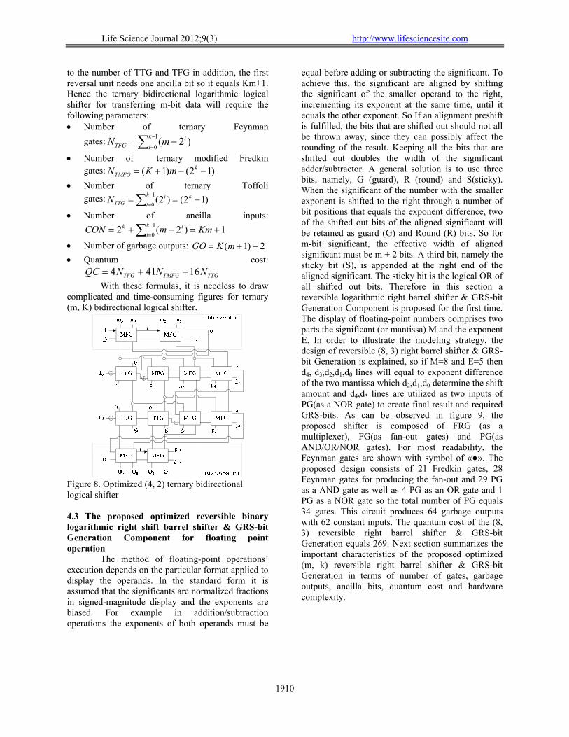
The method of floating-point operations’ execution depends on the particular format applied to display the operands. In the standard form it is assumed that the significants are normalized fractions in signed-magnitude display and the exponents are biased. For example in addition/subtraction operations the exponents of both operands must be
equal before adding or subtracting the significant. To achieve this, the significant are aligned by shifting the significant of the smaller operand to the right, incrementing its exponent at the same time, until it equals the other exponent. So If an alignment preshift is fulfilled, the bits that are shifted out should not all be thrown away, since they can possibly affect the rounding of the result. Keeping all the bits that are shifted out doubles the width of the significant adder/subtractor. A general solution is to use three bits, namely, G (guard), R (round) and S(sticky). When the significant of the number with the smaller exponent is shifted to the right through a number of bit positions that equals the exponent difference, two of the shifted out bits of the aligned significant will be retained as guard (G) and Round (R) bits. So for m-bit significant, the effective width of aligned significant must be m + 2 bits. A third bit, namely the sticky bit (S), is appended at the right end of the aligned significant. The sticky bit is the logical OR of all shifted out bits. Therefore in this section a reversible logarithmic right barrel shifter & GRS-bit Generation Component is proposed for the first time. The display of floating-point numbers comprises two parts the significant (or mantissa) M and the exponent E. In order to illustrate the modeling strategy, the design of reversible (8, 3) right barrel shifter & GRS-bit Generation is explained, so if M=8 and E=5 then d4, d3,d2,d1,d0 lines will equal to exponent difference of the two mantissa which d2,d1,d0 determine the shift amount and d4,d3 lines are utilized as two inputs of PG(as a NOR gate) to create final result and required GRS-bits. As can be observed in figure 9, the proposed shifter is composed of FRG (as a multiplexer), FG(as fan-out gates) and PG(as AND/OR/NOR gates). For most readability, the Feynman gates are shown with symbol of «●». The proposed design consists of 21 Fredkin gates, 28 Feynman gates for producing the fan-out and 29 PG as a AND gate as well as 4 PG as an OR gate and 1 PG as a NOR gate so the total number of PG equals 34 gates. This circuit produces 64 garbage outputs with 62 constant inputs. The quantum cost of the (8, 3) reversible right barrel shifter & GRS-bit Generation equals 269. Next section summarizes the important characteristics of the proposed optimized (m, k) reversible right barrel shifter & GRS-bit Generation in terms of number of gates, garbage outputs, ancilla bits, quantum cost and hardware complexity.
Life Science Journal 2012;9(3) http://www.lifesciencesite.com
1911
Figure 9. The proposed optimized (8, 3) reversible right barrel shifter & GRS-bit Generation component
4.3.1 The Performance Evaluation
In the (m, k) reversible optimized right barrel shifter & GRS-bit Generation, if m is total number of mantissa bits, k is the shift value and E is the number of exponent bits then this circuit will have K+1 rows which the number of required PG gates in each stage equals i22 , 1,...,1,0 ki thus K stages will have
a total of
1
022
k
i
i Peres gates. As well as the last
row((K+1)th row) is constructed by
k
i
i
02 number
of Peres gates as AND gates, m‒4 PGs is required to make OR gate for producing sticky bit and E‒K‒1 PGs is also needed to implement NOR gate. Thus K+1 stages will have
)1()4(2220
1
0
KEm
k
i
ik
i
i which is
82 2 KEmN kPG
number of Peres gates.
The proposed barrel shifter requires m‒1 Fredkin gates for each stage. So the circuit can be realized with at least )1( mKNFRG
number of Fredkin
gates. Every stage in proposed shifter is denoted by i, so the number required FG gates in
1,...,1,0 ki equals immmm 21,...,21,21,21 210
respectively. It means that the total number of
Feynman gates equals
1
02)1(
k
i
imK which is
12)1( kFG mKN .
DC inputs and outputs DC inputs and outputs are an important figure of merit to evaluate a design. In this section, the required formula for calculation of constant inputs and garbage outputs is presented. The number of constant inputs is commensurate to the number of Peres gates and Feynman gates so it equals
9225)1( kEkmNN kPGFG . In
each row, every PG as an AND gate and Fredkin gate produce one garbage output except the last Peres gate that generates two DC outputs which is
1)32( 2 KNFRGk . As well as every PG
produces two garbage outputs for implementing NOR and OR gates which are )1(2 KE and
)4(2 m . Thus, the (m, k) reversible optimized right
barrel shifter & GRS-bit Generation produces
12222)2( 2 KEKKm garbage outputs.
Quantum cost and hardware complexity Two most significant criterions for evaluation of reversible circuits are QC and Total logical calculation. So these factors can be calculated by the functions bellow:
PGFRGFG NNNQC 45 (1)
)2()242()( PGFRGFG NNNT
(2)
Life Science Journal 2012;9(3) http://www.lifesciencesite.com
1912
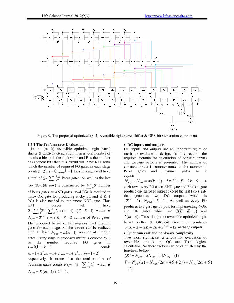
4.4 The Proposed optimized reversible binary normalization barrel shifter for floating point arithmetic
A floating-point number is normalized if the most significant digit of the mantissa is nonzero. In this way the mantissa contains the maximum possible number of significant digits. When two numbers are subtracted, the result may contain most significant zeros as shown in the following example: 0.11100101 ×25 0.11011110 ×25
0.00000111 ×25
In the above example, the result number is necessary to shift left five times to obtain 0.11100000 ×20. In other words, the mantissa has an underflow if the most significant bit in position m7 is zero. In this case, the mantissa is shifted left and the exponent decremented. The bit in m7 is checked again and the process is repeated until it equals 1. When m7 = 1, the mantissa is normalized and the operation is completed, but loop is not possible in reversible logic. In this reason, the proposed normalization shifter must be able to shift mantissa necessary number with receiving the position of the first bit one from left. In order to illustrate the modeling strategy, we follow an example. If Proposed (8, 3) reversible normalization barrel shifter which is depicted in figure 10 takes
0000010101234567 mmmmmmmm as data
inputs then data will be shifted to the left through 5-bits for normalization. M2 is the position of the first bit one from left. It means that the position of first
one bit is “010” thus the select lines of barrel shifter
must be one’s complement of 101010 012 ddd .
In other words the selecting lines in normalization left barrel shifter equal one’s complement of position of the first one bit in result mantissa. The proposed normalization barrel shifter for floating point arithmetic has been implemented using NOT, FRG and FG. This circuit is optimized due to the standing Peres gates instead of FRG gates which have zero inputs in common left barrel shifter. The Proposed optimized (m, K) reversible binary normalization left
barrel shifter requires 1,...,1,0,2 kii Peres gates
for each stage so it will have a total
1
02
k
i
i PGs.
The number requirement Fredkin gates in each stage
equals )2( im thus K stages will have a total of
1
02
k
i
ikm FRGs. The number of FG gates in each
stage is )2( im hence the circuit can be realized
with )12()2(1
0
kk
i
i Kmm Feynman gates.
The required parameters for evaluation of this circuit are calculated as bellow: Number of ancilla inputs:
KmmNNCONk
i
ik
i
iFGPG
1
0
1
0)2(2
Number of garbage outputs: )1( mKGO
Quantum cost: PGFRGFG NNNQC 45
Hardware complexity:
)2()242()( PGFRGFG NNNT
Figure 10. The proposed optimized (8, 3) reversible Normalization left barrel shifter
Life Science Journal 2012;9(3) http://www.lifesciencesite.com
1913
Figure 11. Simulation result of the proposed optimized (4, 2) Reversible bidirectional logical barrel shifter
Figure 12. Simulation result of the optimized (8, 3) reversible right barrel shifter & GRS-bit
Figure 13. Simulation result of the proposed optimized (8, 3) reversible Normalization left barrel shifter
Life Science Journal 2012;9(3) http://www.lifesciencesite.com
1914
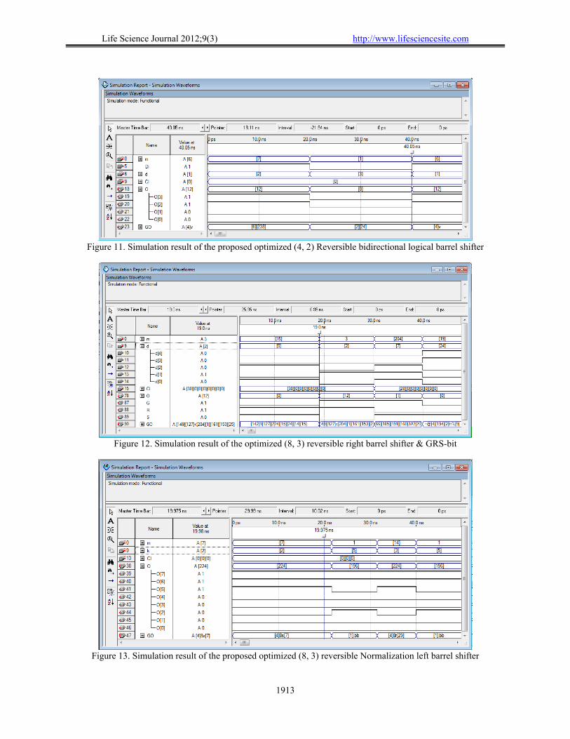
5. Simulation Results
VHDL stands for VHSIC (Very High Speed Integrated Circuits) Hardware Description Language. VHDL is commonly used to write text models that describe a logic circuit. It is a powerful language that allows you to describe and simulate complex digital systems. VHDL simulation environments provide ways of applying test vectors to the inputs of the circuit. The Quartus software supports Verilog HDL and VHDL languages. The proposed optimized (4, 2) Reversible bidirectional logical barrel shifter, optimized (8, 3) Reversible right barrel shifter & GRS-bit generation and optimized (8, 3) Reversible normalization logical left barrel shifter are implemented using VHDL code and simulated using Quartus Simulator. The Figures 11, 12 and 13 show an output waveform of proposed designs for several data test sets.
6. Conclusions and Future Work
Many of papers have worked on reversible binary/ternary rotating barrel shifters, but very little has been focused on non-rotating barrel shifter. So this article proposed an optimized reversible binary/ternary non-rotating barrel shifter. On the other hand, a few of researchers have concentrated on designing the required circuits for reversible floating-point units, thus this research proposed optimized reversible binary logarithmic right shift barrel shifter & GRS-bit Generation Component and binary normalization barrel shifter for floating point arithmetic for the first time. The proposed optimized binary shifters are designed using Feynman gates, Fredkin gates and Peres Gates. Some parameters such as the amount of garbage outputs, the number of constant inputs, size of the circuit and quantum cost, are very important criteria in reversible logic design. So, all of the proposed designs have been evaluated in terms of aforementioned parameters. Two reversible four-bit bidirectional logical barrel shifters have been compared in terms of necessary factors and according to the obtained results from table 2, the proposed optimized barrel shifter is better than common barrel shifter in terms of QC and hardware complexity. In this research, the reversible optimized ternary bidirectional logical barrel shifter is also presented for the first time. The proposed optimized circuits are also generalized for m-bit operands and necessary formulas for computing the number of required gates, number of DC outputs/inputs, quantum cost and hardware complexity are suggested. With these formulas, it is needless to draw complicated and time-consuming figures for computing the parameters of the reversible binary
and ternary proposed barrel shifters. Future related work could design the combinational of rotating and non-rotating barrel shifters as well as optimize one or more of evaluations metrics in proposed circuits. REFERENCES 1. Landauer R. Irreversibility and heat generation in
the computing process. IBM J. Res. Develop 1961. 5(3):183-191.
2. Bennett C. Logical reversibility of computation. IBM J. Res. Develop 1973. 17(6):525–532.
3. Muthukrishnan A, Stroud C R, Jr. Multivalued logic gates for Quantum computation. phys. Rev. A 2000. 62(5):1-8.
4. Klimov A C, Guzman R, Retamal J C, Saavedra C, Qutrit quantum computer with trapped ions. Phys. Rev. A 2003. 67(5):1-7.
5. Hugh D Mc, Twamley J. Trapped-ion qutrit spin molecule quantum computer. New journal of physics 2005. 7(1):1-5.
6. Bullock S S, O’leary D P, Brennen G K. Asymptotically optimal quantum circuits for d-level systems. Physical Review Letters 2005. 94(23): 230502.
7. Curtis E, Perkowski M. A transformation based algorithm for ternary reversible logic synthesis using universally controlled ternary gates. Proceedings of the IWLS 2004, Tamecula, CA, USA, 2004. Pages: 345 – 352.
8. Denler N, Yen B, Perkowski M, Kerntopf P. Synthesis of reversible circuits from a subset of Muthukrishnan–Stroud quantum multi-valued gates. Proceedings of the IWLS 2004, Tamecula, CA, USA, 2004.
9. Khan M H A, Perkowski M A, Khan M R, Kerntopf P. Ternary GFSOP minimization using Kronecker decision diagrams and their synthesis with quantum cascades. Journal of Multiple-Valued Logic and Soft Computing 2005. 11(5-6): 567–602.
10. Khan M H A, Perkowski M A. Genetic algorithm based synthesis of multi output ternary functions using quantum cascade of generalized ternary gates. Proceedings of the 2004 IEEE Congress on Evolutionary Computation, Portland, Oregon, USA, 2004. Pages:2194–2201.
11. Khan M H A, Perkowski M A, Khan M R. Ternary Galois field expansions for reversible logic and Kronecker decision diagrams for ternary GFSOP minimization. Proceedings of the 34th IEEE International Symposium on Multiple-Valued Logic, Toronto, Canada, 2004. Pages: 58–67.
12. Khan M H A, Perkowski M A, Kerntopf P. Multi-output Galois field sum of products synthesis with new quantum cascades. Proceedings of the 33rd IEEE International Symposium On Multiple-Valued Logic, Tokyo, Japan, 2003. Pages: 146–153.

Life Science Journal 2012;9(3) http://www.lifesciencesite.com
1915
13. Miller D M, Dueck G, Maslov D. A synthesis method for MVL reversible logic. Proceedings of the 34th IEEE International Symposium On Multiple-Valued Logic, Toronto, Canada, 2004. Pages:74–80.
14. Perkowski M, Al-rabadi A, Kerntopf P. Multiple-valued quantum logic synthesis. Proceedings of the 2002 International Symposium on New Paradigm VLSI Computing, Sendai, Japan 2002. Pages: 41–47.
15. Yen B, Tomson P, Perkowski M. Sum of non-disjoint cubes covering generation for multi-valued systems of base 2 for use in Muthukrishnan–Stroud quantum realizable gates: an extension of the EXOR covering problem. Proceedings of IWLS 2005.
16. Khan M H A, Perkowski M A. Quantum ternary parallel adder/subtractor with partially-look-ahead carry. Journal of System Architecture 2007. 53(7): 453–464.
17. Khan M H A, Perkowski M A. Quantum realization of ternary encoder and decoder. Proceedings of 7th International Symposium on Representations and Methodology of Future Computing Technologies, Tokyo, Japan, 2005. Pages: 23 – 27.
18. Khan M H A. Design of reversible/quantum ternary multiplexer and demultiplexer. Engineering Letters 2006. 13(2):65–69.
19. Voyiatzis I, Gizopoulos D, Paschalis A. Accumulator-Based Test Generation for Robust Sequential Fault Testing in DSP Cores in Near-Optimal Time. IEEE Transactions on Very Large Scale Integration (VLSI) Systems 2005. 13(9): 1079– 1086.
20. Walus K, Dysart T J, Jullien G A, Budiman R A. QCA Designer: A Rapid Design and Simulation Tool for Quantum-Dot Cellular Automata. IEEE Transactions on Nanotechnology 2004. 3(1): 26-31.
21. Conway T. Galois Field Arithmetic Over GF(pm) For High-Speed/Low-Power Error-Control Applications. IEEE Transactions on Circuits and Systems 2004. 51(4): 709-717.
22. boroumand S, Haghparast M. A Novel Nanometric Fault Tolerant Reversible Associative Memory Cell. Australian Journal of Basic and Applied Sciences 2011. 5(10):945-950.
23. Rangaraju H G, Venugopal U, Muralidhara K. N, Raja K. B. Low Power Reversible Parallel Binary Adder/Subtractor. International J. VLSI Design & Communication Systems (VLSICS) 2010. 1(3):23-34.
24. Feynman R. Quantum Mechanical Computers. Optics News 1985. 11(2):11-20.
25. Haghparast M, Mohammad M, Navi K, Eshghi M. Optimized Reversible Multiplier Circuit. J. Circuits, Systems and Computers 2009. 18(2): 311-323.
26. Hosseini Nia N, Haghparast M. Design of a Novel Nanometric Parity Preserving Reversible Diminished-One Modulo 2n+1 Adder Using Circular Carry Selection. Pesearch Journal of Applied Sciences Engineering and Technology 2012. 4(1):20-26.
27. Khan A I, Nusrat N, Khan S M, Hasan M, Khan M H A. Quantum Realization of Some Ternary Circuits Using Muthukrishnan-Stroud Gates. 37th
IEEE international symposium on Multiple-Valued Logic Oslo 2007. Pages: 20.
28. Paul Gigliotti, Implementing Barrel Shifters Using Multipliers, XAPP195 (v1.1) August 17, 2004.
29. Pillmeier M R, Schulfe M J, Walters E G. Design alternatives for barrel shifters. Proceedings- spie the international society for optical engineering 2002. 57(4791): 436-447.
30. Gorgin S, Kaivani A. Reversible Barrel Shifters. IEEE/ACS International Conference on Computer System and applications 2007. Pages: 479 – 483.
31. Hashmi I, Hasan Babu H Md. An Efficient Design of a Reversible Barrel Shifter. 23rd IEE International Conference on VLSI Design 2010. pages: 93-98
32. Kotiyal S, Thapliyal H, Ranganathan N. Design of a Ternary Barrel Shifter Using Multiple-Valued Reversible Logic. 10th IEEE international conference on Nanotechnology, Seoul, Korea 2010. Pages: 1104-1108.
33. Ravish Aradhaya H V, Lakshmesha J, Muralidhara K N. Design optimization of Reversible Logic Universal Barrel Shifter for Low Power applications. International Journal of Computer Applications 2012. 40(15):0975 – 8887.
34. Kotiyal S, Thapliyal H, Ranganathan N. Design of a Reversible bidirectional Barrel Shifter. 11th IEEE international conference on Nanotechnology, Portland, Oregon 2011. Pages:463-468.
35. Koren I. Computer Arithmetic Algorithms. 2end Edition, University of Massachusetts, Amherst 1945. ISBN: 1-56881-160-8.
36. PENG V, SAMUDRALA S, GAVRIELOV M. On the implementation of shifters, multipliers and dividers in VLSI floating-point units. IEEE 8th Symposium on Computer Arithmetic 1987. Pages: 95-102.
08/08/2012