Life extension, upgrade and repair of welded structures ... · Life extension, upgrade and repair...
19
Life extension, upgrade and repair of welded structures – Towards the use of High Strength Steels Zuheir Barsoum KTH – Royal Institute of Technology, Stockholm, Sweden Khalifa University, Abu Dhabi, UAE Contact: [email protected], [email protected] 1 st World Congress and Exhibition on Construction & Steel Structures, Nov 16-18 2015, Dubai, Crown Plaza.
-
Upload
trinhnguyet -
Category
Documents
-
view
235 -
download
0
Transcript of Life extension, upgrade and repair of welded structures ... · Life extension, upgrade and repair...
Life extension, upgrade and repair of welded structures – Towards the use of High Strength
Steels
Zuheir Barsoum
KTH – Royal Institute of Technology, Stockholm, Sweden
Khalifa University, Abu Dhabi, UAE
Contact: [email protected], [email protected]
1st World Congress and Exhibition on Construction & Steel Structures, Nov 16-18 2015,
Dubai, Crown Plaza.

Fatigue of Welded Structures
Welds have much lower strength than the base materials due to: • Stress concentration due to local weld shape and joint geometry • Weld defects and flaw which leads to early crack propagation • High tensile welding stresses
Parent Material Compared to Welded Joints
2

Improving the Fatigue Strength of Welded Structures
Increased Service Life
Good design practice
• Minimize fatigue loads, e.g. by
avoiding resonance &
vibration
• Use low SCF joints
• Avoid corrosion
• Place welds in areas with low
stress
High quality fabrication
• Good choice of plate and
weld materials and process
• Good weld penetration,
groove geometry
• Weld quality inspection w.
correlation to fatigue life
Improvement techniques
• Applied during fabrication
• Post fabrication treatment
Geometry modification techniques
• Local stress peaks are reduced
• Lower SCF
• Surface quality is improved
• Tensile welding residual stresses are reduced
Residual stress techniques
• High local compressive residual
stresses are introduced
• Material work hardening
• Phase changes in weld material gives
compressive stresses
• Surface quality is improved
• Lower SCF 3
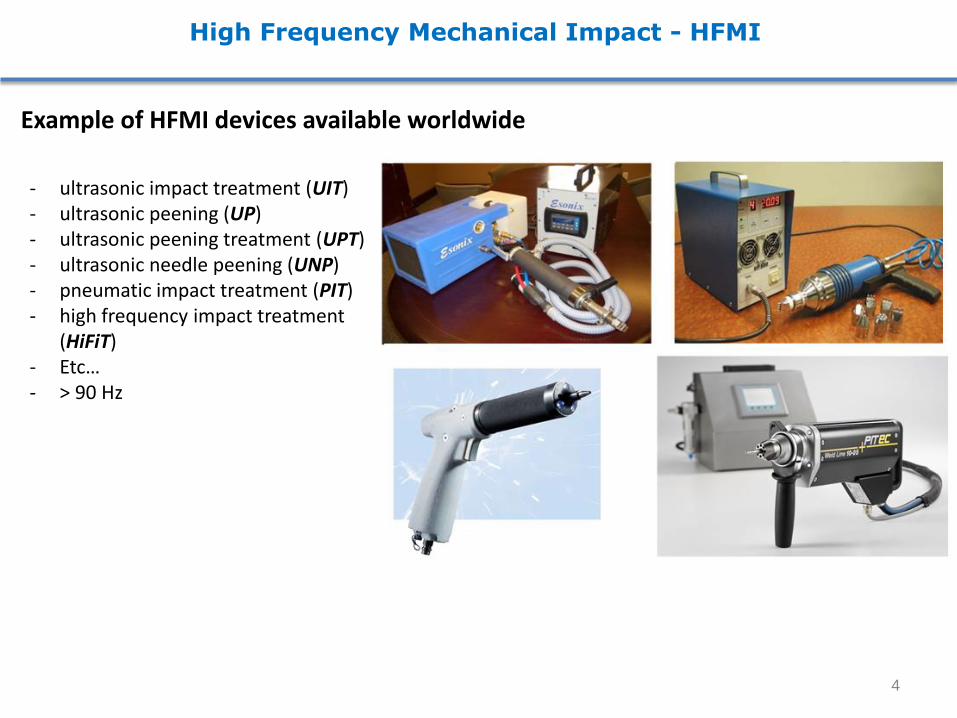
High Frequency Mechanical Impact - HFMI
Example of HFMI devices available worldwide
- ultrasonic impact treatment (UIT) - ultrasonic peening (UP) - ultrasonic peening treatment (UPT) - ultrasonic needle peening (UNP) - pneumatic impact treatment (PIT) - high frequency impact treatment
(HiFiT) - Etc… - > 90 Hz
4

High Frequency Mechanical Impact - HFMI
Example of HFMI indenter sizes and configurations
Typical weld toe profile in the as-welded condition and following HFMI treatment
5

What Does the Current IIW Guidelines Say?
fy (MPa) longitudinal welds transverse welds butt welds
1as-welded, m = 3
all fy 71 80 90
2improved by hammer or needle peening, m = 3
fy ≤ 355 90 100 112
355 < fy 100 112 125
1) Hobbacher, A.: IIW Recommendations for Fatigue Design of Welded Joints and Components., WRC Bulletin 520, The Welding Research Council, New York. (2009)
2) Haagensen, P. J., Maddox, S. J.: IIW Recommendations on methods for improving the fatigue lives of welded joints, Woodhead Publishing Ltd., Cambridge. International Institute of Welding, Paris. (2013)
3) Fricke, W.: IIW Recommendations for the Fatigue Assessment of Welded Structures by Notch Stress Analysis, Woodhead Publishing Ltd., Cambridge. (2012)
Nominal stress : Existing IIW FAT classes
6

Proposed Fatigue Strength Improvement using HFMI
Some of Assumptions: • The improvement method covered in these studies is applied to the weld toe • All of fatigue design methods for HFMI improved welds are based on an assumed S-N
slope of m = 5 and fatigue strength improvement factors are defined at N = 2106 cycles
Examples of joints suitable for improvement
7
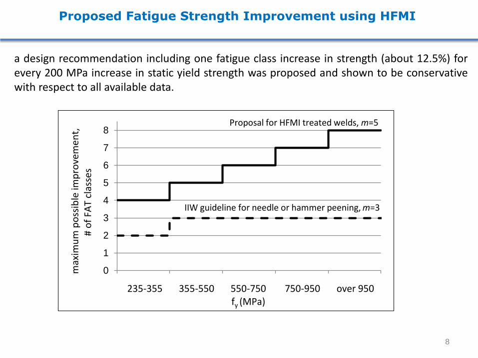
Proposed Fatigue Strength Improvement using HFMI
a design recommendation including one fatigue class increase in strength (about 12.5%) for every 200 MPa increase in static yield strength was proposed and shown to be conservative with respect to all available data.
0
1
2
3
4
5
6
7
8
0 1 2 3 4 5235-355 355-550 550-750 750-950 over 950
fy (MPa)
max
imu
m p
oss
ible
imp
rove
me
nt,
#
of
FAT
cla
sse
s
IIW guideline for needle or hammer peening, m=3
Proposal for HFMI treated welds, m=5
8
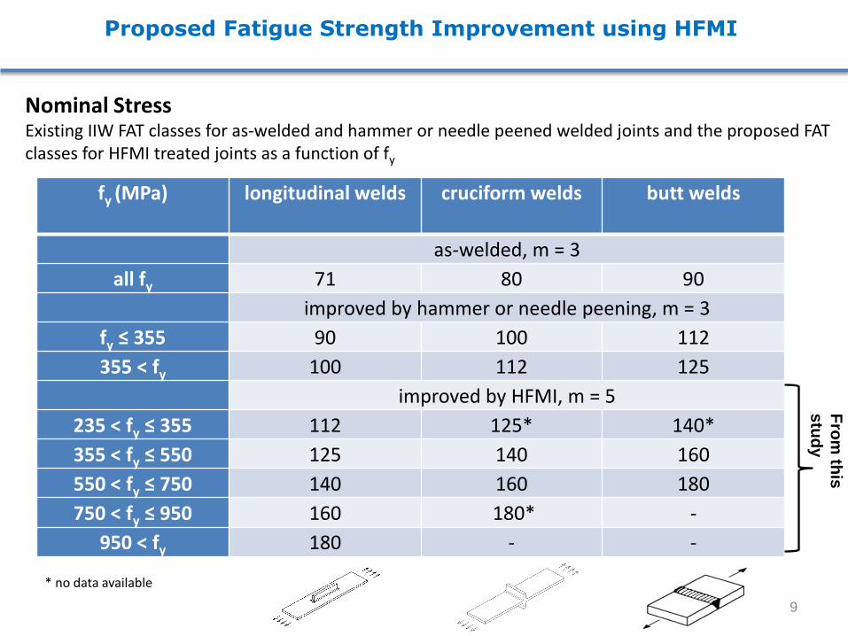
Proposed Fatigue Strength Improvement using HFMI
Nominal Stress Existing IIW FAT classes for as-welded and hammer or needle peened welded joints and the proposed FAT classes for HFMI treated joints as a function of fy
* no data available
fy (MPa) longitudinal welds cruciform welds butt welds
as-welded, m = 3
all fy 71 80 90
improved by hammer or needle peening, m = 3
fy ≤ 355 90 100 112
355 < fy 100 112 125
improved by HFMI, m = 5
235 < fy ≤ 355 112 125* 140*
355 < fy ≤ 550 125 140 160
550 < fy ≤ 750 140 160 180
750 < fy ≤ 950 160 180* -
950 < fy 180 - -
Fro
m th
is
stu
dy
9
Proposed Fatigue Strength Improvement using HFMI
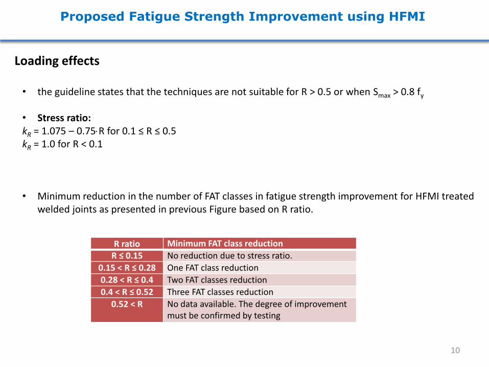
Loading effects • the guideline states that the techniques are not suitable for R > 0.5 or when Smax > 0.8 fy
• Stress ratio: kR = 1.075 – 0.75R for 0.1 ≤ R ≤ 0.5 kR = 1.0 for R < 0.1 • Minimum reduction in the number of FAT classes in fatigue strength improvement for HFMI treated
welded joints as presented in previous Figure based on R ratio.
R ratio Minimum FAT class reduction
R ≤ 0.15 No reduction due to stress ratio.
0.15 < R ≤ 0.28 One FAT class reduction
0.28 < R ≤ 0.4 Two FAT classes reduction
0.4 < R ≤ 0.52 Three FAT classes reduction
0.52 < R No data available. The degree of improvement must be confirmed by testing
10
Proposed Fatigue Strength Improvement using HFMI
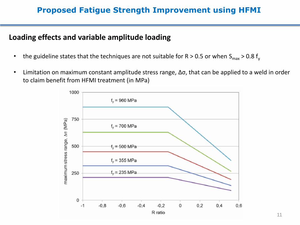
Loading effects and variable amplitude loading • the guideline states that the techniques are not suitable for R > 0.5 or when Smax > 0.8 fy
• Limitation on maximum constant amplitude stress range, Δσ, that can be applied to a weld in order
to claim benefit from HFMI treatment (in MPa)
11

Proposed Fatigue Strength Improvement using HFMI
The influence of steel strength : • Computed cycle limit below which HFMI is not expected to result in fatigue strength improvement
as a function of steel strength.
fy (MPa) N (cycles)
< 355 72 000
355 – 550 30 000
550 – 750 12 500
> 750 < 10 000
12
Proposed Procedures and Quality Assurance Guidelines for HFMI
Procedures Operator Training: - 1-2 days of operator training - identification of fatigue critical regions is also important to avoid extra costs and
treatment Weld Preparation: - weld profile quality level B in ISO 5817 : Undercuts, Excessive overfill, Excessive concavity and
Overlaps.
- proper weld profile Safety Aspects: - less noise and vibration - eight hour work shift
13
Proposed Procedures and Quality Assurance Guidelines for HFMI
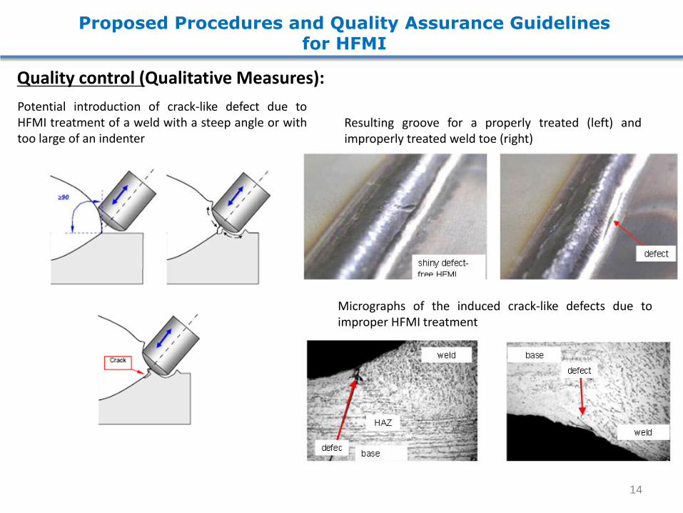
Quality control (Qualitative Measures): Potential introduction of crack-like defect due to HFMI treatment of a weld with a steep angle or with too large of an indenter
Resulting groove for a properly treated (left) and improperly treated weld toe (right)
Micrographs of the induced crack-like defects due to improper HFMI treatment
14

Proposed Procedures and Quality Assurance Guidelines for HFMI
Quality control (Qualitative Measures):
- No thin line representing original fusion line should be visible the groove , No individual strikes visible
thin crack-like defect which reduces or eliminates the effectiveness of the HFMI treatment
defect-free groove but with individual indenter strike still visible indicating the need for additional passes
15
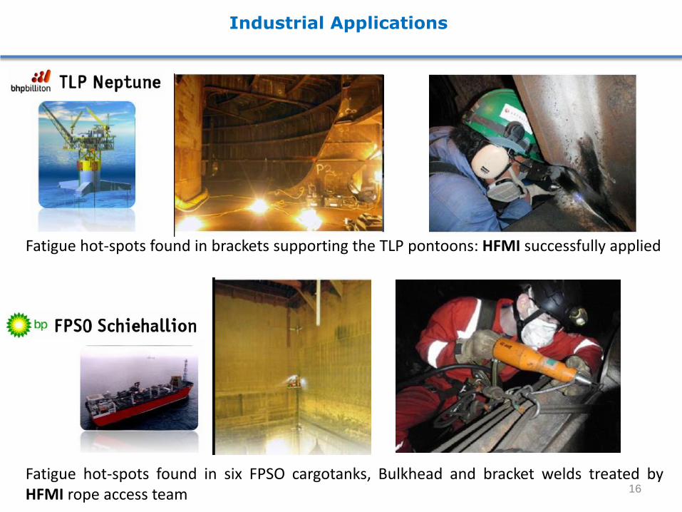
Industrial Applications
Fatigue hot-spots found in brackets supporting the TLP pontoons: HFMI successfully applied
Fatigue hot-spots found in six FPSO cargotanks, Bulkhead and bracket welds treated by HFMI rope access team 16

Conclusions
• The design proposal is considered to apply to plate thickness 5 to 50 mm and for 235 MPa ≤ fy ≤ 960 MPa.
• Fatigue resistance curves for HFMI improved welds are based on an assumed S-N slope of m = 5 in the region 1104 ≤ N < 1107 cycles and, for variable amplitude loading, m’ = 9 for 1107 ≤ N.
• Stress assessment may be based on nominal stress, structural hot spot stress or effective notch stress using stress analysis procedures as defined by the IIW.
• The design proposal includes proposals for the 1) effect of material strength, 2) special requirements for low stress concentration weld details, 3) high R-ratio loading conditions and 4) variable amplitude loading.
• A companion document concerning relevant equipment, proper procedures, material requirements, safety, training requirements for operators and inspectors, quality control measures and documentation has also been prepared and is published in this same issue.
• Succesful validation have been shown on larger industrial welded structures
17

Recent Publications
HFMI Guidelines Publications (Welding in the World, 2013 and 2014)
18

Thank You for Your Kind Attention!
Questions?
19