LIFE EXPECTANCY ANALYSIS PROGRAM - ics … · ¾ Negative Ic/Ir values are indicative of the flow...
17
S.No. 8266012 ABB Sweden(Skellefteå Kraft AB) - 1 - ABB Ltd. L L I I F F E E E E X X P P E E C C T T A A N N C C Y Y A A N N A A L L Y Y S S I I S S P P R R O O G G R R A A M M Customer ABB Sweden (Skellefteå Kraft AB) Machine S.No. 8266012 LEAP Level LB+LS Date of data receipt August 3,2009 Date of report despatch September 16,2009 Tested By Yngve Anundsson Report Prepared By Ameet Choughule Report Approved By Cajetan Pinto
Transcript of LIFE EXPECTANCY ANALYSIS PROGRAM - ics … · ¾ Negative Ic/Ir values are indicative of the flow...
S.No. 8266012 ABB Sweden(Skellefteå Kraft AB)
- 1 - ABB Ltd.
LLIIFFEE EEXXPPEECCTTAANNCCYY AANNAALLYYSSIISS PPRROOGGRRAAMM
Customer ABB Sweden (Skellefteå Kraft AB)
Machine S.No. 8266012
LEAP Level LB+LS
Date of data receipt August 3,2009
Date of report despatch September 16,2009
Tested By Yngve Anundsson
Report Prepared By
Ameet Choughule
Report Approved By Cajetan Pinto
S.No. 8266012 ABB Sweden(Skellefteå Kraft AB)
- 2 - ABB Ltd.
INDEX
Sr. No. DESCRIPTION PAGE NO.
1. SUMMARY 3
2. RECOMMENDATIONS 3
3. MACHINE DETAILS 5
4. COMMENTS 6
6. LIFE EXPECTANCY ANALYSIS 8
7. MEASUREMENT & ANALYSIS (APPENDIX) 10

S.No. 8266012 ABB Sweden(Skellefteå Kraft AB)
- 3 - ABB Ltd.
SUMMARY The following is the analysis for the stator winding insulation: There is evidence of the presence of contamination on the surface of the windings, though not excessive. There are no signs of cracks or localized damage in the insulation as is seen from the volume resistivity values obtained There is no evidence of damage or erosion to the corona protection shield. There is evidence of the presence of mobile ions in the insulation as a result of de-polymerization of the resin, in the vicinity of discharging voids. The stage of de-polymerization of the resin can be described as “mid-life” Discharging in internal de-laminations is the dominant mode of discharge activity. The extent of discharging air spaces, measured by the discharging void volume content, is higher than what is normally observed in epoxy mica insulation systems. On the basis of the operating data and the measurements performed on the machine tested the stator winding has been in operation for 38% of the expected life of its insulation. With the existing operation conditions the remaining life of the stator insulation system is estimated to 130 000 hours. The life expectancy analysis has been done with a confidence level of 80%.
SUMMERING AV GENOMFÖRDA MÄTNINGAR
Notera att mätningarna endast är gjorda på maskinens statorlindning och att alla slutsatser gäller statorn.
• Mätningen visar tecken på nedsmutsning av statorlindningen, dock ej kraftig
• Utifrån värdet på volym resistivitet ses inte något problem med lokala skador eller sprickor i isolationssystemet
• Inga tecken på skador eller nedbrytning av spårglimmskyddet kan ses
• Analysen visar på fria joner i isolationssystemet kommande från nedbrytningen av hartsen, nedbrytningen kan tolkas som ”medelålder”. Dominerande PD aktivitet är intern PD kommande från delaminering av isolationssystemet, nivån mätt i urladdnings aktivitet som funktion av håligheter är högre än vad som är normalt för denna typ av isolationssystem
• Baserat på givna driftdata och genomförda mätningar beräknas den använda livslängden till 38 % och den återstående livslängden på statorns isolationssystem till 130 000 timmar vid oförändrade driftsförhållanden. Konfidensnivån på den genomförda livslängdsberäkningen är 80 %, vilket innebär att i snitt 8 av 10 st statorer uppnår den beräknade livslängden.
RECOMMENDATIONS
The following recommendations are made considering the stator winding alone: Inspection and Maintenance: Based on the lifetime expectancy analysis and the condition of the machine insulation, the machine has been in operation for a period of around 38 % of the expected lifetime of the stator winding.

S.No. 8266012 ABB Sweden(Skellefteå Kraft AB)
- 4 - ABB Ltd.
The following maintenance and inspection intervention schedule is therefore recommended for the stator windings: An L4 inspection of the stator windings should be performed at the earliest available opportunity but not greater than 25 000 hours from the time of measurements. The inspection and maintenance action to be performed on the stator windings during the prescribed intervention is mentioned below: Maintenance Actions From the condition of the machine stator windings analyzed, the following are the recommended actions: The windings should be cleaned of surface contaminants and heated to dispel surface moisture/solvent residues. Inspections: In addition to providing a maintenance opportunity for the recommended maintenance actions, the inspection helps cover the portions of the winding that cannot be evaluated in a LEAP Standard inspection e.g. end-winding support system, specific localized damage areas, wedge tightness, etc. Inspection of the end-winding areas After cleaning the end-windings, the areas around ties/lashing supports of the stator end-windings should be inspected for partial discharge damage and for developing looseness of the supporting ties. End-winding portions of the stator should be examined for localized areas of discoloration
INSPEKTION OCH UNDERHÅLL Notera att alla rekommendationer gäller statorn, för maskinens övriga delar, som t.ex. lager, rotor och kylare rekommenderas underhåll enligt maskinens manual. Baserat på den beräknade återstående livslängden och statusen på statorns isolationssystem, bedöms statorns åldring uppgå till över 38 % av dess förväntade totala livslängd. Framtida underhåll på statorn utifrån analyserat data: En L4 inspektion inklusive rotorutdrag rekommenderas vid nästa möjliga servicetillfälle men inom 25 000 ekvivalenta timmar inklusive;
• Detaljerad rengöring av statorlindningen inklusive torkning för att säkerställa att ingen kvarvarande fukt finns i statorn
• Vid inspektion bör också detaljer av statorlindningen genomgås som inte inkluderas i LEAP analysen;
o Härvkorgsupport o Lokala skador på isolationssystemet o Fastsättning av spårkilar.
S.No. 8266012 ABB Sweden(Skellefteå Kraft AB)
- 5 - ABB Ltd.
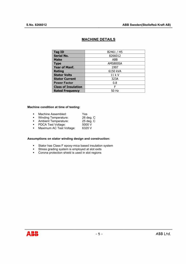
MACHINE DETAILS
Tag ID B2461 / H5 Serial No. 8266012 Make ABB Type AMS800SA Year of Manf. 1997 Rating 6150 kVA Stator Volts 11 k V Stator Current 323A Power Factor 0.8 Class of Insulation F Rated Frequency 50 Hz
Machine condition at time of testing:
� Machine Assembled: Yes � Winding Temperature: 26 deg. C � Ambient Temperature: 25 deg. C � PDCA Test Voltage: 5000 V � Maximum AC Test Voltage: 6320 V
Assumptions on stator winding design and construction:
� Stator has Class F epoxy-mica based insulation system � Stress grading system is employed at slot exits � Corona protection shield is used in slot regions

S.No. 8266012 ABB Sweden(Skellefteå Kraft AB)
- 6 - ABB Ltd.
COMMENTS: The details of measurements and analyzed parameters with the glossary can be found in the Appendix.
• CONTAMINATION: There is evidence of the presence of contamination on the surface of the windings, though not excessive, for the following reasons:
¾ From charge stored when individual phases are tested compared to charge stored when all three phases are simultaneously checked, and from Q2/Q3 ratios, there is evidence of end-winding contamination. Since the charge storage on the end-windings is not high the extent of contamination is not significant.
¾ The dispersion ratio is greater than what is normally observed in Class F epoxy mica insulation systems. On closer examination, this is largely due to high charge storage in the slot region.
¾ The Ic/Ir value obtained when all three phases are simultaneously tested is indicative of the nature of the dominant current that flows on the surface of the end-windings at the slot ends.
¾ This current is seen to be predominantly capacitive in nature, indicating that the contaminant at the slot ends, could precipitate charge storage effects and could essentially be in the form of oil mixed with moisture or other non-conductive contaminants.
¾ Negative Ic/Ir values are indicative of the flow of currents being controlled by electrochemical charge storage effects, or by presence of homo-polar charges.
¾ Homo-polar charges can be created by the presence of moisture in the contaminant or due to excessive humidity, or even due to the presence of metal oxides residues such as iron oxide from magnetic slot wedge wear or slot discharging effects.
¾ The volume resistivity values are within the normal range for Class F epoxy-mica windings and possibility of cracks or localized defects in insulation is remote.
• CONDITION OF THE CORONA PROTECTION SHIELD:
There is no evidence of damage or erosion to the corona protection shield used in the winding from to the following:
¾ The dominant partial discharge activity, as recognized from the partial discharge patterns recorded and the magnitudes of the discharge activity, is not that of slot discharge activity, but of internal /surface discharges.
¾ There is some evidence of lack of electrical contact of the outer layer of the windings (corona protection shield) in the slot area with the slot from the Q1/Q2 ratios. This is attributed to constructional features of the winding, with the possible presence of insulating resin in localized areas between the corona protection shield and the slot in some areas, and not due to damage of the corona protection shield.
• CONDITION OF THE STRESS GRADE SYSTEM:
There is no damage/modification to the properties of the stress grading system at the slot ends due to the following reasons:
¾ The partial discharge patterns obtained do not indicate any dominant slot end discharge activity. Surface discharge activity is observed in the U & V phases, but no damage to stress grading system is observed.
¾ The variation of tan delta and capacitance with voltage below discharge inception, is seen to be linear in nature. This behaviour is essentially governed by the surface properties of the windings at the slot ends.
¾ The effective phase shift values reflect the properties of semi-conductive stress grading system used at the slot ends. These values are seen to be uniform for all three phases.
S.No. 8266012 ABB Sweden(Skellefteå Kraft AB)
- 7 - ABB Ltd.
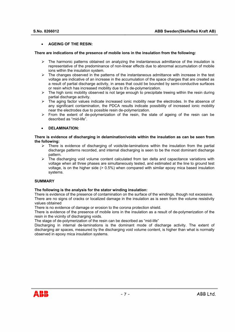
• AGEING OF THE RESIN: There are indications of the presence of mobile ions in the insulation from the following:
¾ The harmonic patterns obtained on analyzing the instantaneous admittance of the insulation is representative of the predominance of non-linear effects due to abnormal accumulation of mobile ions within the insulation system.
¾ The changes observed in the patterns of the instantaneous admittance with increase in the test voltage are indicative of an increase in the accumulation of the space charges that are created as a result of partial discharge activity, in areas that could be bounded by semi-conductive surfaces or resin which has increased mobility due to it's de-polymerization.
¾ The high ionic mobility observed is not large enough to precipitate treeing within the resin during partial discharge activity.
¾ The aging factor values indicate increased ionic mobility near the electrodes. In the absence of any significant contamination, the PDCA results indicate possibility of increased ionic mobility near the electrodes due to possible resin de-polymerization.
¾ From the extent of de-polymerization of the resin, the state of ageing of the resin can be described as “mid-life”.
• DELAMINATION:
There is evidence of discharging in delamination/voids within the insulation as can be seen from the following:
¾ There is evidence of discharging of voids/de-laminations within the insulation from the partial discharge patterns recorded, and internal discharging is seen to be the most dominant discharge pattern.
¾ The discharging void volume content calculated from tan delta and capacitance variations with voltage when all three phases are simultaneously tested, and estimated at the line to ground test voltage, is on the higher side (> 0.5%) when compared with similar epoxy mica based insulation systems.
SUMMARY The following is the analysis for the stator winding insulation: There is evidence of the presence of contamination on the surface of the windings, though not excessive. There are no signs of cracks or localized damage in the insulation as is seen from the volume resistivity values obtained There is no evidence of damage or erosion to the corona protection shield. There is evidence of the presence of mobile ions in the insulation as a result of de-polymerization of the resin in the vicinity of discharging voids. The stage of de-polymerization of the resin can be described as “mid-life” Discharging in internal de-laminations is the dominant mode of discharge activity. The extent of discharging air spaces, measured by the discharging void volume content, is higher than what is normally observed in epoxy mica insulation systems.

S.No. 8266012 ABB Sweden(Skellefteå Kraft AB)
- 8 - ABB Ltd.
LIFE EXPECTANCY ANALYSIS A combined stress phenomenological model, that is based on one proposed originally by Simoni, Srinivas, et al, is used to assess the extent of degradation of the insulation and perform a lifetime expectancy analysis. The model accounts for thermal, electrical and mechanical stresses, whose relative effects on the life of the insulation are estimated on the basis of the analysis from the measurements performed, and from the operating and historical details made available. The theory stems from the fact that when stresses act on the insulation of the stator windings, there is a progressive deterioration of the strength of the insulation. In other words, ageing is exhibited by a progressive deterioration of the physical properties of the insulation. Not all physical properties can give an indication of the progression of ageing, except perhaps those directly related to failure, e.g. electrical breakdown strength and mechanical strength. If stresses unable to produce a failure are considered such as temperature or chemical exposure, other failure criteria are selected that are related to electrical or mechanical breakdown strengths. In any case, failure essentially occurs when the selected property drops down to a limiting value, so that a unique definition can be adopted for remaining life – the time for the selected property to reach that point. This point is generally related to the stresses that are developed in the stator insulation during machine operation. In other words, when the strength of the insulation deteriorates to a point where it equals the developed stresses in the insulation, the insulation will fail. The measurements performed during an inspection are converted into parameters that can be related to the stresses that are developed in the insulation, for example the extent to air space within insulation would affect thermal, mechanical and electrical properties of the insulation and thereby affect the thermal electrical and mechanical stresses that are developed in the insulation. This affects the rate of deterioration of the insulation. To give another example, when the temperature of the insulation increases, the rate of deterioration of the mechanical strength of the insulation also increases. Therefore, based on the knowledge of how parameters derived from measurements can affect stresses, it is possible to estimate the rate of deterioration of the strength of the insulation. In the case of LEAP Standard measurements performed, the parameters that have been used as inputs from the analysis include the charge distribution parameters, the volume resistivity, the discharging void content parameters, partial discharge parameters and data from the non-linear analysis. These parameters are used together with operating data such as winding temperature and the number of starts, to draw the line describing the deterioration in insulation strength, as indicated by the dashed red line. It is generally assumed that at the time of commissioning of the machine, there is no deterioration of the relevant properties of the insulation. An initial life estimate, indicated by the solid red line up to the time of inspection and projected by the dashed green line, is made on the basis of “normal” expected parameters (as derived from operating data and the normal range values of measurements such as those specified for LEAP Standard inspections) at an early part of the machine life. Operational hours: 50,000 Starts/stops: 1500 Equivalent hours: 80,000 (Op. Hours + 20 * Starts/Stops)
Maximum Winding Temperature: 63 Deg C

S.No. 8266012 ABB Sweden(Skellefteå Kraft AB)
- 9 - ABB Ltd.
LIFE EXPECTANCY ANALYSIS @ 63 deg C (With 80 % Confidence Level)
0
10
20
30
40
50
60
70
80
90
100
0 50 100 150 200 250 300 350
Equivalent Hours ( x 1000)
% L
Ife U
sed
Up
Insulation degradation curve (designed) Remaining Life (present) Present Life
Designed LifeEstimate
Present LifeEstimate
On the basis of the operating data and the measurements performed on the stator, the expected life of the stator winding insulation is estimated to be an additional 130 000 hours with the existing operating conditions. The above life expectancy analysis is done with a confidence level of 80 %. .
a) The above estimation is based on the measurements performed by ABB and historical and operating data of the machine, made available to ABB, considering steady state conditions only.
b) The life estimation is based on the assessment of the stator ground-wall insulation only. Models are used that describe known wearing out and ageing processes of the ground-wall insulation of the stator windings.
c) It is assumed in the analysis, that future operating conditions of the machine will be similar to the historical operating data made available to ABB.
d) Any transient stresses that may be manifested on the windings, such as switching and/ external line transients, etc., could result in insulation failure prior to estimated life (pre-mature failure).
e) The aim of life estimation study is aimed at developing a maintenance plan for the stator winding. ABB disclaims warranty of merchantability or fitness for intended purpose.
f) LEAP is a process and not a one time event. Re-evaluation of measurements over a period of time will help reduce the effect of the assumptions made and could increase the confidence level of the analysis.

S.No. 8266012 ABB Sweden(Skellefteå Kraft AB)
- 10 - ABB Ltd.
MEASUREMENTS & ANALYSIS
POLARISATION-DEPOLARISATION CURRENT ANALYSIS (PDCA) Test Voltage: 5000 V dc Winding temperature during measurement: 26 deg Celsius Analysis is performed on 35 deg base.
U V W UVW NORMAL RANGE
IR (INSULATION RESISTANCE) [MΩ] 9006 9127 9325 3735 -----
PI (POLARIZATION INDEX) 6.89 9.20 9.23 12.54 >2
T1 (ION MIGRATION TIME CONSTANT) [secs] 17.67 14.93 16.30 17.79 10 – 30 Sec
T2 (SLOW RELAXATION TIME CONSTANT) [secs] 80.31 69.13 78.69 82.31 65 – 150 Sec
T3 (INTERFACIAL POLARIZATION TIME CONSTANT) [secs]
434.94 409.41 429.64 457.31 300 – 1000 Sec
Q1 (CHARGE - ION MIGRATION) [%] 21.09 19.97 21.45 22.19 < 7%
Q2 (CHARGE - SLOW RELAXATION) [%] 13.65 14.57 14.43 12.71 < 10%
Q3 (CHARGE - INTERFACIAL POLARIZATION) [%] 16.51 16.96 15.59 11.28 < 20%
AGEING FACTOR -- -- -- 37.77 35 – 100
CI (ION CONCENTRATION INDEX) -- -- -- 0.0467 15E-3 – 25E-3
Ic/Ir -3.47 -6.33 -2.64 -7.07 -----
Co/C∞ (DISPERSION RATIO) 1.51 1.52 1.51 1.46 < 1.25
I∞ (CHARGING CURRENT AT LONG TIMES) [μA] 0.0462 0.0285 0.0267 0.0530 -----
VOLUME RESISTIVITY (Log Scale) 14.306 14.519 14.547 14.718 > 14

S.No. 8266012 ABB Sweden(Skellefteå Kraft AB)
- 11 - ABB Ltd.
Polarization-Depolarization Currents
U PHASE
0.01
0.10
1.00
10.00
100.00
1000.00
1 10 100 1000Time (sec)
Pol-D
epol
Cur
rent
s (m
icro
Am
p)
Charging Discharging
Polarization-Depolarization CurrentsV PHASE
0.01
0.10
1.00
10.00
100.00
1000.00
1 10 100 1000Time (sec)
Pol-D
epol
Cur
rent
s (m
icro
Am
p)
Charging Discharging
Polarization-Depolarization CurrentsW PHASE
0.01
0.10
1.00
10.00
100.00
1000.00
1 10 100 1000Time (sec)
Pol-D
epol
Cur
rent
s (m
icro
Am
p)
Charging Discharging
Polarization-Depolarization CurrentsUVW PHASE
0.01
0.10
1.00
10.00
100.00
1 10 100 1000Time (sec)
Pol-D
epol
Cur
rent
s (m
icro
Am
p)
Charging Discharging
TAN DELTA MEASUREMENTS
0.4
0.6
0.8
1
1.2
1.4
1.6
1.8
1.00 2.00 3.00 4.00 5.00 6.00 7.00
Voltage (kV)
Tan
Del
ta (%
)
U Phase V Phase W Phase UVW phase
CAPACITANCE MEASUREMENTS
57500
58000
58500
59000
59500
60000
1.00 2.00 3.00 4.00 5.00 6.00 7.00
Voltage (kV)
Cap
acita
nce
- Ind
Ph.
(pF)
171600
172000
172400
172800
173200
173600
Cap
acita
nce
- UVW
Ph
. (pF
)
U Phase V Phase W Phase UVW phase

S.No. 8266012 ABB Sweden(Skellefteå Kraft AB)
- 12 - ABB Ltd.
TAN DELTA & CAPACITANCE MEASUREMENTS
U Phase V Phase W Phase UVW Phase Voltage
(kV) TD (%) CAP(pF) TD (%) CAP (pF) TD (%) CAP (pF) TD (%) CAP (pF) 1.07 0.53457 57916 0.50428 58431 0.5315 58431 0.58156 171850 2.01 0.70772 58381 0.70036 58864 0.73459 59073 0.77263 172220 3.04 0.88677 58412 0.87163 58892 0.89938 59113 0.92415 172420 4.06 1.0627 58526 1.0606 59001 1.0557 59204 1.0631 172610 5.08 1.2502 58619 1.2261 59091 1.2814 59311 1.2589 172900 6.32 1.5791 58795 1.5075 59235 1.549 59457 1.5331 173460
Calculated parameters:
U V W UVW Effective Phase Shift (deg) 23.04 32.44 24.03 46.20 Base Tan Delta Tdo (%) 0.34 0.31 0.36 0.41 Base Capacitance Co (pF) 57730 58360 58363 171576 Discharge Inception Voltage (kV) 3.04 4.06 4.06 3.10 Void Volume Content (%) 1.05 0.86 1.07 0.63 Effective Phase of Discharge (deg) -7.10 -5.20 -8.12 45.97
NON-LINEAR INSULATION BEHAVIOUR ANALYSIS (NLIBA)
At 3kV: U V W UVW
1. OVERALL HARMONIC CONTENT. (%)
38.07 41.69 28.94 14.19
2. PREDOMINANT HARMONICS EVEN EVEN EVEN EVEN
At 6 kV: U V W UVW
3. OVERALL HARMONIC CONTENT. (%)
22.36 21.92 20.87 12.54
4. PREDOMINANT HARMONICS EVEN EVEN EVEN EVEN

S.No. 8266012 ABB Sweden(Skellefteå Kraft AB)
- 13 - ABB Ltd.
NON-LINEAR ANALYSISU PHASE
0
2
4
6
8
10
12
14
1 2 3 4 5 6 7 8 9 10 11 12 13 14 15 16 17
Multiples of fundamental frequency
Ove
rall
Har
mon
ic M
agni
tude
@ 7
.6
kV (%
)
0
3
6
9
12
15
18
21
Ove
rall
Har
mon
ic M
agni
tude
@
4kV(
%)
@ 7.6 kV @ 4 kV
NON-LINEAR ANALYSISV PHASE
0
2
4
6
8
10
12
14
1 2 3 4 5 6 7 8 9 10 11 12 13 14 15 16 17
Multiples of fundamental frequency
Ove
rall
Har
mon
ic M
agni
tude
@
7.6k
V (%
)
0
4
8
12
16
20
24
28
Ove
rall
Har
mon
ic M
agni
tude
@ 4
kV
(%)
@ 7.6 kV @4 kV
NON-LINEAR ANALYSISW PHASE
0
2
4
6
8
10
12
14
16
1 2 3 4 5 6 7 8 9 10 11 12 13 14 15 16 17
Multiples of fundamental frequency
Ove
rall
Har
mon
ic M
agni
tude
(%)
@ 4 kV @ 7.6 kV
NON-LINEAR ANALYSISUVW PHASE
0
1
2
3
4
5
6
7
8
9
10
1 2 3 4 5 6 7 8 9 10 11 12 13 14 15 16 17
Multiple of fundamental frequency
Ove
rall
Har
mon
ic A
mpl
itude
(%)
@ 4 kV @7.6 kV
EVEN HARMONICS (Low Voltage)
0
5
10
15
20
25
2 4 6 8 10 12 14 16
EVEN
HA
RM
ON
IC M
AG
NIT
UD
ES (a
rbitr
ary
units
)
U
V
W
UVW
EVEN HARMONICS (High Voltage)
0
2
4
6
8
10
12
14
2 4 6 8 10 12 14 16
EVEN
HA
RM
ON
IC M
AG
NIT
UD
ES (a
rbitr
ary
units
)
U
V
W
UVW

S.No. 8266012 ABB Sweden(Skellefteå Kraft AB)
- 14 - ABB Ltd.
PARTIAL DISCHARGE ANALYSIS (PDA)
U Phase @ 6.54 kV V Phase @ 6.44 kV
W Phase @ 6.48 kV
UVW Phase @ 6.51 kV

S.No. 8266012 ABB Sweden(Skellefteå Kraft AB)
- 15 - ABB Ltd.
Appendix GLOSSARY
¾ Charge storage: The charge storage takes place due to various mechanisms such as,
• Space charge polarization: The alignment of electric dipoles within the insulation on application of
electric field results in accumulation of charges in a region such as near the electrodes (copper and iron) in the slots and in the end winding sections, due to the inefficient exchange of charges in these areas. This is called space charge polarization.
• Interfacial polarization: The migration and accumulation of charge between two different dielectrics that have different dielectric constants (such as that between layers of mica-epoxy, between machine insulation and contaminant, between machine insulation and airspace, etc) gives rise to interfacial polarization. The Q2 charges usually reflect charge accumulation at interfaces within slot section, while Q3 charges usually reflect charge accumulation on the endwinding, on the basis of a distributed capacitor-resistor model that is used to describe surface conditions on the endwinding.
The proportional distribution of these charges (as seen from values of Q1/Q2 and Q2/Q3) gives an indication of the charge storage process that may be dominant. A greater proportion of charge stored near the electrodes could possibly indicate (high Q1/Q2, for thermosetting systems), a loss of electrical contact of the outer surface of the coil with the core. This may be due to high coil side clearances/ wedge looseness or damage/ degradation/ modification of the properties/erosion of the slot discharge prevention shield or even an insulating layer between the corona protection and the slot. It could also indicate possible overheating of the coil surface in contact with the core, or aging/overheating of the insulation in close proximity of the conductor stack, large gaps between the ground-wall insulation and the conductor stack. ¾ Ic/Ir Ratio: Ic/Ir ratios are calculated by considering the current in the range of 1000 secs expressed as a power law curve, and essentially is representative of the flow of capacitive and resistive currents on the endwinding surface. The model used, most closely represents the situation when all three phases are simultaneously tested. The analysis is meaningful only when the presence of contaminants are indicated from other analysis such as charge storage. The ratio is meant to be indicative of the nature of the contaminant at the slot ends. Values near 1 and less than 1 have been observed in windings contaminated by carbon particles/carbonized oil (conductive contaminants) or other conductive dust deposition at the slot ends. In case of oil/grease type contaminants, discontinuity in the stress grading system at the slot ends, the values are greater than 1. Negative values are at times observed due to the creation of homopolar charges at the slot end regions, due to the present of moisture in the contaminant or on the surface of the windings or even when there is iron oxide in the contaminant.
¾ Aging Factor (AF): This factor gives an indication of the state of resin in close vicinity of the electrodes, in terms of the concentration and mobility of its mobile ions. The values are around 100 for new machines. However, when reduced values are obtained it indicates depolymerisation of resin and aging of insulation near the electrodes. Extremely low values of AF (<35) could also be obtained if the windings are contaminated with dirt and the contaminant penetrates into the insulation, in and around electrode regions.
¾ Ion Concentration index (CI): There are always mobile ions found within the insulation, but these are generally dispersed within the insulation. During a polarization process theses charges get trapped in
Space charge polarization (Q1) and Interfacial polarization (Q2) In SLOT region
Interfacial polarization (Q3) in ENDWINDING region
S.No. 8266012 ABB Sweden(Skellefteå Kraft AB)
- 16 - ABB Ltd.
certain regions of the winding insulation. The number of mobile ions per unit volume is represented by the Ion Concentration Index. The greater the ion concentration, the higher is the possibility of charge injection within the insulation. The ion concentration index is generally reflective of the charge concentrations near the electrodes, or at interfaces. The permissible values lie between 0.015 to 0.025.
¾ Dispersion ratio: The ratio of the capacitance required to store the charge obtained from the winding during the discharging process, to the geometrical capacitance of the windings, is referred to as the Dispersion ratio. Values computed for clean and dry insulation normally do not exceed 1.2. Dispersion ratio values have been seen to exceed 1.2, a) if there is a dispersive contaminant present in or on the windings, e.g. carbon, particularly when mixed with oil, or moisture present in the contaminant or in the windings, b) if there is a loss of contact of the outer surface of the coil with the core, and the presence of an insulation between the anti corona shield and core (as is sometimes seen in VPI windings), c) in cases of advanced aging of the insulation.
¾ Tan delta: Tan δ is a measure of the energy spent in the dielectric medium as a result of dipolar polarization, interfacial polarization, space charge polarization and partial discharge effects. Tan delta variations with voltage occur as a result of contamination, ageing, lack of resin cure, delaminated insulation, stress grading systems, and partial discharges, and hence is useful indicator of the insulation health.
¾ Discharge inception voltage: It is the voltage at which partial discharge activity is initiated. The point generally coincides with the point, which the tan d curve with voltage suddenly rises sharply.
¾ Void volume content: Discharges in the insulation could occur in voids or air spaces that may be present in the insulation system if the electric field and air gap size (based on Paschen’s Law) would permit. The volume of discharging voids in the insulation reflects the integrity of the insulation, and is a good indicator of the insulation health. The discharging void volume content can be evaluated from the variation of the capacitance and tanδ above discharge inception.
¾ Effective phase of discharging: The effective phase of discharging is estimated from the variation of tan delta and capacitance with voltage above discharge inception. The effective phase is calculated on the basis that all losses and capacitance changes due to partial discharge effects (from internal slot or surface discharging) could effectively occur at an effective phase angle, which is calculated.
¾ Effective phase shift: The effective phase shift is computed from the variation of C-Tan �ҏmeasurements with voltage. In the case of machines employing stress grading systems at the sot ends, the variation of capacitance and tan delta with voltage below discharge inception is seen to be linear. The effective phase shift characterizes the stress grading system, and therefore indicates whether properties of stress grading system are modified / deteriorated. Note that when values are greater than 35 deg, the variations are influenced by the conductive properties of the stress grading system or the agent of modification, at the slot exits. Similarly values lower than 20deg is indicative of capacitive influences.
¾ Harmonic content: The instantaneous variation of the insulation capacitance with time is plotted from the time waveforms of the voltage and the current data obtained. A harmonic analysis is performed on the instantaneous capacitance-time variation waveform.
Harmonic plots are generally seen to be with even harmonic predominance and with reducing magnitudes as the harmonic number increases.
¾ Even to Odd Ratio: This ratio helps us to identify which harmonics (even or odd), are most dominant. Reasons for non-linear behavior of the insulation could either be conductive or charge storage based. Odd harmonic predominance is seen when there are conductive reasons for non-linear behavior, while even harmonic predominance is indicated when the behavior is controlled by charge storage effects.
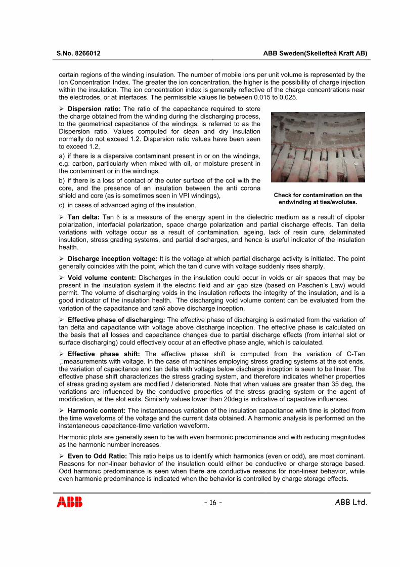
Check for contamination on the
endwinding at ties/evolutes.

S.No. 8266012 ABB Sweden(Skellefteå Kraft AB)
- 17 - ABB Ltd.
© Copyright ABB Ltd. Some of the tests and analysis mentioned in this test report are developed within ABB Ltd. and is property of the same. Unauthorized reproduction of any part of the report, duplication of the report without prior consent of ABB Ltd will be considered illegal.
ABB Limited Survey No. 110, Behind Kingfisher Factory, Near Nanak Nutrition Factory, Village: Vavanje
MIDC Taloja, Dist.: Raigad, Maharashtra, INDIA Email: [email protected],[email protected]

![Proposals to Extend Healthy Life Expectancy in Shizuoka ...€¦ · [Gap between life expectancy and healthy life expectancy in Shizuoka Prefecture] Healthy life expectancy *Source:](https://static.fdocuments.in/doc/165x107/5f427921a09c2479a15262fb/proposals-to-extend-healthy-life-expectancy-in-shizuoka-gap-between-life-expectancy.jpg)