Lichtschranken Baureihe WL 27-2W 36 Photoelectric · PDF fileLichtschranken Baureihe WL 27-2W...
14
U 306 SENSICK CATALOGUE Lichtschranken Baureihe WL 27-2 W 36 Photoelectric switches W 36: Mastering complex tasks reliably Users have long appreciated the benefits of the W 36 series of photoelectric switches. Thanks to their design, the devices can be used both indoors and outdoors, since all DC types are suitable for temperatures ranging from – 40 to + 55 °C and polarising filters also make it possible to detect shiny surfaces. The scanning ranges of the W 36 series speak for themselves: 60 metres for the WS/WE 36 through-beam photoelectric switch, 22 metres for the WL 36 photoelectric reflex switch and 800 mm for the WT 36 photo- electric proximity switch, which also offers adjustable scanning distance and background suppression. Great demands are often placed on the mechanical endurance of sensors. Suitable enclosure rat- ings (depending on the type of connection) of IP 65 and IP 67, robust plastic housings, pre- failure signalling output and indi- cator, and insensitivity to ambient light ensure reliable switching in hostile industrial environments. Universal voltage versions, time delay, test input and selectable light- or dark-switching are additional characteristic features of the W 36 series. Photoelectric proximity switches, BGS Photoelectric reflex switches Through-beam photoelectric switches
Transcript of Lichtschranken Baureihe WL 27-2W 36 Photoelectric · PDF fileLichtschranken Baureihe WL 27-2W...

U
306 SENSICK CATALOGUE
Lichtschranken Baureihe WL 27-2W 36 Photoelectric switches
W 36: Mastering complex
tasks reliably
Users have long appreciated the
benefits of the W 36 series of
photoelectric switches. Thanks to
their design, the devices can be
used both indoors and outdoors,
since all DC types are suitable
for temperatures ranging from
–40 to + 55 °C and polarising
filters also make it possible to
detect shiny surfaces. The
scanning ranges of the W 36
series speak for themselves:
60 metres for the WS/WE 36
through-beam photoelectric
switch, 22 metres for the WL 36
photoelectric reflex switch and
800 mm for the WT 36 photo-
electric proximity switch, which
also offers adjustable scanning
distance and background
suppression.
Great demands are often placed
on the mechanical endurance of
sensors. Suitable enclosure rat-
ings (depending on the type of
connection) of IP 65 and IP 67,
robust plastic housings, pre-
failure signalling output and indi-
cator, and insensitivity to ambient
light ensure reliable switching in
hostile industrial environments.
Universal voltage versions, time
delay, test input and selectable
light- or dark-switching are
additional characteristic features
of the W 36 series.
Photoelectric proximity switches,BGS
Photoelectric reflex switches
Through-beamphotoelectricswitches

307SENSICK CATALOGUE
W 36
m WL 36 photoelec-
tric reflex switches
checking the pre-
sence of beer crates
before automatic
removal of the bottle
caps.
n Hot or cold, wet,
dry or dusty – WL 36
photoelectric reflex
switches are design-
ed for use under
hostile operating
conditions indoors
and outdoors – here
they are being used
on the roll-up gate of
a carwash.
v WL 36 sensors used to detect mesh
baskets in front of a goods lift.
m Making sure
that crates are full:
WL 36 photoelectric
reflex switches used
to count coloured
bottles before
packaging.

0.015 – 0.3 s with DC only 0.5 – 12 s with DC 0.5 – 12 s with UC
t 0 without time delay t 0 without time delay t 0 without time delay
t 1 ON-delay t 3 ON-delay t 1 ON-delay
t 2 OFF-delay t 4 OFF-delay t 2 OFF-delay
WT 36 Photoelectric proximity switches, infrared light -- DC/UC, plug connection
308 SENSICK CATALOGUE
20
6428
34
85
6
max.
13
2822
65
77
36
ø5.5
62
11
2
6
7
3
4
14
5
5
1
Distance
t
0.015-0.3 s
t0 t0
t3 t1
t4 t2
0.5-12 s
Distance
t
Rel. off
Rel. on
t0 t0
t1 t1
t2 t2
0.5-12s
1
2
3
4
Q
1L+
M3
2
4Q
1
2
4
1L+
M2
3
4
Q
Q
55
66
TE
NC7
1
2
3
4
5
1L1
N
NC
NC
2
3
4
5
6
7
Standard direction of the material being scanned
Alignment sight
Centre of optical axis, receiver
Centre of optical axis, sender
LED signal strength indicator
M5 threaded mounting hole – 5.5 mm deep
Mounting holes,
recesses on both sides for M5 hex nuts
Time delay selector switch with DC,
time delay and light-/dark-switching selector
switches with UC
Light-switching
Dark-switching
Time control
Scanning distance adjustment
8
01
Photoelectric proximity switches
Scanning distance200. . .800 mm
Robust plastic housing
Infrared light
Selectable time delay
Dimensional drawing
WT 36-N 410
WT 36-P 410
WT 36-N 710
WT 36-P 710
WT 36-R 710
Adjustments possible
Switch-selectable time delay
Connection types
C V
Accessories page
Mounting brackets 510
Cable receptacles 496
7
9
8
01
9
X
6
5
4
3
2
1
WT 36-N 410 WT 36-N 710 WT 36-R 710
4-pin, M 12 7-pin 7-pin
WT 36-P 410 WT 36-P 710
WT 36
309SENSICK CATALOGUE(mm) 300 400 500 600 700 800
25
20
15
10
5
0% o
f scannin
g d
ista
nce
1
2
6%/90%
18%/90%
200 600
200 800
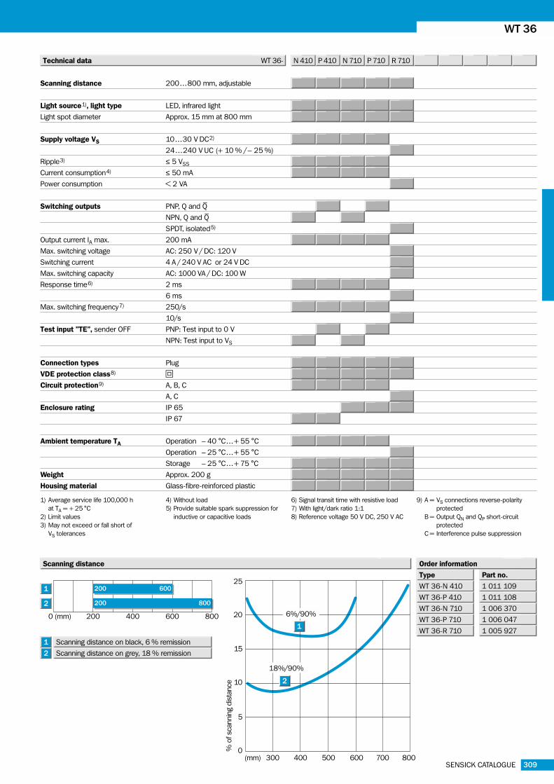
Technical data WT 36- N 410 P 410 N 710 P 710 R 710
Type Part no.
1 011 109
Order information
WT 36-N 410
1 011 108WT 36-P 410
1 006 370WT 36-N 710
1 006 047WT 36-P 710
1 005 927WT 36-R 710
Scanning distance
1) Average service life 100,000 h
at TA = + 25 °C
2) Limit values
3) May not exceed or fall short of
VS tolerances
4) Without load
5) Provide suitable spark suppression for
inductive or capacitive loads
9) A = VS connections reverse-polarity
protected
B = Output QN and QP short-circuit
protected
C = Interference pulse suppression
6) Signal transit time with resistive load
7) With light/dark ratio 1:1
8) Reference voltage 50 V DC, 250 V AC
1
2
Scanning distance on black, 6 % remission1
Scanning distance on grey, 18 % remission2
0 (mm) 200 400 600 800
Scanning distance 200. . .800 mm, adjustable
Light source1), light type LED, infrared light
Light spot diameter Approx. 15 mm at 800 mm
Supply voltage VS 10. . .30 V DC2)
24 . . .240 V UC (+ 10 % /– 25 %)
Ripple3) ≤ 5 VSS
Current consumption4) ≤ 50 mA
Power consumption < 2 VA
Switching outputs PNP, Q and Q–
NPN, Q and Q–
SPDT, isolated5)
Output current IA max. 200 mA
Max. switching voltage AC: 250 V / DC: 120 V
Switching current 4 A / 240 V AC or 24 V DC
Max. switching capacity AC: 1000 VA / DC: 100 W
Response time6) 2 ms
6 ms
Max. switching frequency7) 250/s
10/s
Test input ”TE”, sender OFF PNP: Test input to 0 V
NPN: Test input to VS
Connection types Plug
VDE protection class8) V
Circuit protection9) A, B, C
A, C
Enclosure rating IP 65
IP 67
Ambient temperature TA Operation – 40 °C . . .+ 55 °C
Operation – 25 °C . . .+ 55 °C
Storage – 25 °C . . .+ 75 °C
Weight Approx. 200 g
Housing material Glass-fibre-reinforced plastic

310 SENSICK CATALOGUE
WT 36 Photoelectric proximity switches, infrared light -- DC/UC, terminal connection
t0 t0
t3 t1
t4 t2
0.015-0.3s
0.5-12s
t
Distance
1
2
3
4
5
t0 t0
t1 t1
t2 t2
Rel. on0.5-12s
Rel. off
t
Distance
1
2
3
4
5
20
6428
34
85
61
8
2816
88
100
36
ø5.5
62
11
2
6
7
3
4
5
14
5
1
1
2
3
4
5
L+
M
Q
Q
TE
1
2
3
4
5
L1
N
0.015 – 0.3 s with DC only 0.5 – 12 s with DC 0.5 – 12 s with UC
t 0 without time delay t 0 without time delay t 0 without time delay
t 1 ON-delay t 3 ON-delay t 1 ON-delay
t 2 OFF-delay t 4 OFF-delay t 2 OFF-delay
Standard direction of the material being scanned
Alignment sight
Centre of optical axis, receiver
Centre of optical axis, sender
LED signal strength indicator
M5 threaded mounting hole – 5.5 mm deep
Mounting holes,
recesses on both sides for M5 hex nuts
Time delay selector switch with DC,
time delay and light-/dark-switching selector
switches with UC
Light-switching
Dark-switching
Time control
Scanning distance adjustment
Terminal connection
8
Photoelectric proximity switches
Scanning distance200. . .800 mm
Robust plastic housing
Infrared
Adjustable background
suppression
Easily accessible terminal
chamber
Selectable time delay
Dimensional drawing
WT 36-N 210
WT 36-P 210
WT 36-R 210
Adjustments possible
Switch-selectable time delay
Connection types
C V
78
01
11
11
9
6
5
4
3
2
1
WT 36-N 210 WT 36-R 210
PG 11, terminals PG 11, terminals
WT 36-P 210
01
9
X
Accessories page
Mounting brackets 510

311SENSICK CATALOGUE
WL 27-2 WT 36
(mm) 300 400 500 600 700 800
25
20
15
10
5
0% o
f scannin
g d
ista
nce
1
2
6%/90%
18%/90%
200 600
200 800
Technical data WT 36- N 210 P 210 R 210
Type Part no.
1 010 109
Order information
WT 36-N 210
1 010 108WT 36-P 210
1 010 110WT 36-R 210
Scanning distance
1
2
0 (mm) 200 400 600 800
Scanning distance 200. . .800 mm, adjustable
Light source1), light type LED, infrared light
Light spot diameter Approx. 15 mm at 800 mm
Supply voltage VS 10. . .30 V DC2)
24 . . .240 V UC (+ 10 % /– 25 %)
Ripple3) ≤ 5 VSS
Current consumption4) ≤ 50 mA
Power consumption < 2 VA
Switching outputs PNP, Q and Q–
NPN, Q and Q–
SPDT, isolated5)
Output current IA max. 200 mA
Max. switching voltage AC: 250 V / DC: 120 V
Switching current 4 A / 240 V AC or 24 V DC
Max. switching capacity AC: 1000 VA / DC: 100 W
Response time6) 2 ms
6 ms
Max. switching frequency7) 250/s
10/s
Test input ”TE”, sender OFF PNP: Test input to 0 V
NPN: Test input to VS
Connection types Terminal connection
VDE protection class8) V
Circuit protection9) A, B, C
A, C
Enclosure rating IP 67
Ambient temperature TA Operation – 40 °C . . .+ 55 °C
Operation – 25 °C . . .+ 55 °C
Storage – 25 °C . . .+ 70 °C
Weight Approx. 200 g
Housing material Glass-fibre-reinforced plastic
1) Average service life 100,000 h
at TA = + 25 °C
2) Limit values
3) May not exceed or fall short of
VS tolerances
4) Without load
5) Provide suitable spark suppression for
inductive or capacitive loads
9) A = VS connections reverse-polarity
protected
B = Output QN and QP short-circuit
protected
C = Interference pulse suppression
6) Signal transit time with resistive load
7) With light/dark ratio 1:1
8) Reference voltage 50 V DC, 250 V AC
Scanning distance on black, 6 % remission1
Scanning distance on grey, 18 % remission2

312 SENSICK CATALOGUE
WL 36 Photoelectric reflex switches, red light -- DC
20
48
12
52 8
5
6m
ax.
45
2816
60
72
36
ø5.5
62
11
1
5
6
2
3
4
14
4
1
2
3
4
5
6
2 b1 a
t 0
1
2
3
4
5
6
L+
M
Alarm
QP
QN
TE
1
2
3
4
Alarm
1L+
M3
2
4QP
5
1
2
3
4
Alarm
1L+
M2
3
4
QN
QP
55
66
TE
NC7
1
2
3
4
1L+
M
(Alarm)
2
3QP
(QN)5
64
Alignment sight
Centre of optical axis, receiver
Centre of optical axis, sender
LED signal strength indicator
M5 threaded mounting hole – 5.5 mm deep
Mounting holes
recesses on both sides for M5 hex nuts
ON/OFF timer switch
t = Time ON, 0 = Time OFF
Time delay
1 ON-delay
2 OFF-delay
Time control 0.02 to 1 s
Light/dark selector
a = Light-switching, b = Dark-switching
Sensitivity adjustment
Terminal connections
8
Photoelectric reflex switches
Scanning range22 m
Robust plastic housing
Visible red light
Selectable time delay
Dimensional drawing
WL 36-B 230
WL 36-B 430
WL 36-B 730
WL 36-B 330
Adjustments possible
Connection types
C V
Accessories page
Mounting brackets 510
Cable receptacles 496
Attachable heated cover 556
Reflectors 520
7
11
6
5
4
3
2
1
WL 36-B 230 WL 36-B 430 WL 36-B 730 WL 36-B 330
PG 11, terminals 4-pin, M 12 7-pin 3-pin
01
9
8
7
11
21
21
01
9

313SENSICK CATALOGUE
WL 27-2 WL 36
(m) 5 10 15 20 25
100
10
1Opera
ting r
eserv
e
1
3
5
Scanning range,
max. typical
Operating range
0.25 3
22
12
18
16
16
11
0.1 12
0.1 11
0.1 11
0.1 7
0.1 15
0.3 9
Technical data WL 36- B 230 B 430 B 730 B 330
PL 80 A
C 110
PL 50 A
PL 40 A
0.1. . .15.0 m
Operating range
0.3 . . .9.0 m
0.1. . .12.0 m
0.1. . .11.0 m
PL 30 A 0.1. . .11.0 m
PL 20 A 0.1. . .7.0 m
Reflective tape 0.25 . . .3.0 m
«Diamond Grade»
7
6
5
4
3
2
1
Reflector type
Type Part no.
1 005 385
Order information
WL 36-B 230
1 010 612WL 36-B 430
1 008 848WL 36-B 730
1 005 787WL 36-B 330
Operating range and operating reserve
6
7
5
4
3
2
1
0 (m) 4 8 12 16 18 24
Operating range Scanning range, max. typical
1) Average service life 100,000 h
at TA = + 25 °C
2) Limit values
3) May not exceed or fall short of
VS tolerances
4) Without load
9) A = VS connections reverse-polarity
protected
B = Output QN and QP short-circuit
protected
C = Interference pulse suppression
5) Signal transit time with resistive load
6) With light/dark ratio 1:1
7) Signal reserve ≥ 50 %
8) Reference voltage 50 V DC
Scanning range, max. typ./on reflector 22 m /PL 80 A
Sensitivity Adjustable
Light source1), light type LED, red light
Light spot diameter Approx. 50 mm at 3 m
Supply voltage VS 10. . .30 V DC2)
Ripple3) ≤ 5 VSS
Current consumption4) ≤ 40 mA
Switching outputs PNP: QP and NPN QN
PNP: QP
PNP: QP or NPN QN
Light-/dark-switching Switch-selectable
Output current IA max. 200 mA
Response time5) ≤ 1.25 ms
Max. switching frequency6) 400/s
Pre-failure signalling output Alarm, PNP, open collector
Internal resistance ≥ 1.5 kΩ ± 5 %
Operating condition ”correct”7) Output HIGH (VS – 1.5 V)
Operating condition ”faulty” Switching periodically at 5/s to VS
Test input ”TE” Sender switched off
Sender OFF Test input to 0 V
Connection type PG cable gland
Plug
VDE protection class8) V
Circuit protection9) A, B, C
Enclosure rating IP 67
IP 65
Ambient temperature TA Operation – 40 °C . . .+ 55 °C
Storage – 40 °C . . .+ 70 °C
Weight Approx. 165 g
Polarising filter
Housing material Glass-fibre-reinforced plastic

314 SENSICK CATALOGUE
WL 36 Photoelectric reflex switches, red light -- UC
20
48
12
52 8
5
6m
ax.
45
2816
60
72
36
ø5.5
62
11
1
5
6
2
3
4
14
4
1
2
3
4
5
L1
N
1
2
3
4
5
1L1
N
NC
NC
2
3
4
5
6
7
1
2
3
4
5
6
2 b1 a
t 0
Alignment sight
Centre of optical axis, receiver
Centre of optical axis, sender
LED signal strength indicator
M5 threaded mounting hole – 5.5 mm deep
Mounting holes
recesses on both sides for M5 hex nuts
ON/OFF timer switch
t = Time ON, 0 = Time OFF
Time delay
1 ON-delay
2 OFF-delay
Time control 0.5 to 12 s
Light/dark selector
a = Light-switching, b = Dark-switching
Sensitivity adjustment
Terminal connections
8
Photoelectric reflex switches
Scanning range22 m
Robust plastic housing
Visible red light
Easily accessible terminal
chamber
Selectable time delay
Dimensional drawing
WL 36-R 230
WL 36-R 230
Adjustments possible
Connection types
C V
Accessories page
Mounting brackets 510
Cable receptacles 496
Attachable heated cover 556
Reflectors 520
7
11
6
5
4
3
2
1
WL 36-R 230 WL 36-R 730
PG 11, terminals 7-pin
01
9
8
7
11
21
21
01
9

315SENSICK CATALOGUE
WL 27-2 WL 36
(m) 5 10 15 20 25
100
10
1Opera
ting r
eserv
e
1
3
5
Scanning range,
max. typical
Operating range
0.25 3
22
12
18
16
16
11
0.1 12
0.1 11
0.1 11
0.1 7
0.1 15
0.3 9
Technical data WL 36- R 230 R 730
PL 80 A
C 110
PL 50 A
PL 40 A
0.1. . .15.0 m
Operating range
0.3 . . .9.0 m
0.1. . .12.0 m
0.1. . .11.0 m
PL 30 A 0.1. . .11.0 m
PL 20 A 0.1. . .7.0 m
Reflective tape 0.25 . . .3.0 m
«Diamond Grade»
7
6
5
4
3
2
1
Reflector type
Type Part no.
1 005 387
Order information
WL 36-R 230
1 008 849WL 36-R 730
Operating range and operating reserve
6
7
5
4
3
2
1
0 (m) 4 8 12 16 18 24
Operating range Scanning range, max. typical
1) Average service life 100,000 h
at TA = + 25 °C
2) Provide suitable spark suppression for
inductive or capacitive loads
3) With light/dark ratio 1:1
4) Reference voltage 250 V AC
5) A = VS connections reverse-polarity
protected
C = Interference pulse suppression
Scanning range, max. typ./on reflector 22 m /PL 80 A
Sensitivity Adjustable
Light source1), light type LED, red light
Light spot diameter Approx. 50 mm at 3 m
Supply voltage VS 24. . .240 V UC (+ 10 %/– 25 %)
Power consumption < 2 VA
Switching output SPDT, isolated2)
Max. switching voltage AC: 250 V / DC: 120 V
Max. switching current 4 A / 240 V AC or 24 V DC
Max. switching capacity AC: 1000 VA / DC: 100 W
Response time ≤ 20 ms
Max. switching frequency3) 10/s
Light-/dark-switching Switch-selectable
Connection types PG cable gland
Plug
VDE protection class4) V
Circuit protection5) A, C
Enclosure rating IP 67
IP 65
Ambient temperature TA Operation – 25 °C . . .+ 55 °C
Storage – 40 °C . . .+ 70 °C
Weight Approx. 165 g
Polarising filter
Housing material Glass-fibre-reinforced plastic

316 SENSICK CATALOGUE
WS/WE 36 Through-beam photoelectric switches, infrared light -- DC
20
48
12
52 8
5
6m
ax.
45
2816
60
72
36
ø5.5
62
11
1
5
6
2
3
4
14
4
1
2
3
4
5
6
L+
M
Alarm
QP
QN
1
2
3
4
Alarm
1L+
M2
3
4QP
5
1
2
3
4
Alarm
1L+
M2
3
4
QN
QP
55
66
TE
NC7
1
2
3
4
5
6
L+
M
TE
1
2
3 TE
L+
M
1
2
3
4
1L+
M2
5
6 TE
1
2
3
4
5
6
2 b1 a
t 0
Alignment sight
Centre of optical axis, receiver
Centre of optical axis, sender
LED signal strength indicator, top and front
M5 threaded mounting hole – 5.5 mm deep
Mounting holes
recesses on both sides for M5 hex nuts
ON/OFF timer switch
t = Time ON, 0 = Time OFF
Time delay
1 ON-delay
2 OFF-delay
Time control 0.02 to 1 s
Light/dark selector
a = Light-switching, b = Dark-switching
Sensitivity adjustment
Terminal connections
8
Through-beam photoelectric switches
Scanning range60 m
Robust plastic housing
Infrared light
Selectable time delay
Dimensional drawing
WS/WE 36-B 230
WS/WE 36-B 430
WS/WE 36-B 730
Adjustments possible
Connection types
C V
Accessories page
Mounting brackets 510
Cable receptacles 496
Attachable heated cover 556
7
11
6
5
4
3
2
1
PG 11, terminals
Sender
Receiver
4-pin, M 12 7-pin
01
9
8
7
11
21
21
01
9
WS/WE 36-B 230 WS/WE 36-B 430 WS/WE 36-B 730

317SENSICK CATALOGUE
WL 27-2 WS/WE 36
(m) 30 40 50 60
100
10
1Opera
ting r
eserv
e
Operating range
Scanning range, max. typical
60
Technical data WS/WE 36- B 230 B 430 B 730
Type Part no.
1 010 922
Order information
1 011 107
1 011 114
Operating range and operating reserve
0 (m) 10 20 30 40 50 60
Operating range Scanning range,
max. typical
WS/WE 36-B 230
WS/WE 36-B 430
WS/WE 36-B 7300 50
Scanning range, max. typical 60 m
Sensitivity Adjustable
Light source1), light type LED, infrared light
Light spot diameter Approx. 1300 mm at 25 m
Supply voltage VS 10. . .30 V DC2)
Ripple3) ≤ 5 VSS
Current consumption4) ≤ 40 mA
Switching outputs PNP: QP and NPN QN
PNP: QP
Light-/dark-switching Switch-selectable
Output current IA max. 200 mA
Response time5) ≤ 2.5 ms
Max. switching frequency6) 400/s
Pre-failure signalling output Alarm, PNP, open collector
Internal resistance ≥ 1.5 kΩ ± 5 %
Operating condition ”correct”7) Output HIGH (VS – 1.5 V)
Operating condition ”faulty” Switching periodically at 5/s to VS
Test input ”TE” Sender switched off
Sender OFF Test input to 0 V
Connection types PG cable gland
Plug
VDE protection class8) V
Circuit protection9) A, B, C
Enclosure rating IP 67
IP 65
Ambient temperature TA Operation – 40 °C . . .+ 55 °C
Storage – 40 °C . . .+ 70 °C
Weight Approx. 160 g
Housing material Glass-fibre-reinforced plastic
1) Average service life 100,000 h
at TA = + 25 °C
2) Limit values
3) May not exceed or fall short of
VS tolerances
4) Without load
9) A = VS connections reverse-polarity
protected
B = Output QN and QP short-circuit
protected
C = Interference pulse suppression
5) Signal transit time with resistive load
6) With light/dark ratio 1:1
7) Signal reserve ≥ 50 %
8) Reference voltage 50 V DC

318 SENSICK CATALOGUE
WS/WE 36 Through-beam photoelectric switches, infrared light -- UC
20
48
12
52 8
5
6m
ax.
45
2816
60
72
36
ø5.5
62
11
1
5
6
2
3
4
14
4
1
2
3
4
5
L1
N
1
2
3
4
5
1L1
N
NC
NC
2
3
4
5
6
7
1
2
3
4
5
L1
N
1
2
3
4
1L1
N3
5
6
1
2
3
4
5
6
2 b1 a
t 0
Alignment sight
Centre of optical axis, receiver
Centre of optical axis, sender
LED signal strength indicator, top and front
M5 threaded mounting hole – 5.5 mm deep
Mounting holes
recesses on both sides for M5 hex nuts
ON/OFF timer switch
t = Time ON, 0 = Time OFF
Time delay
1 ON-delay
2 OFF-delay
Time control 0.5 to 12 s
Light/dark selector
a = Light-switching, b = Dark-switching
Sensitivity adjustment
Terminal connections
8
Through-beam photoelectric switches
Scanning range60 m
Robust plastic housing
Infrared light
Easily accessible terminal
chamber
Selectable time delay
Dimensional drawing
WS/WE 36-R 230
WS/WE 36-R 730
Adjustments possible
Connection types
C V
Accessories page
Mounting brackets 510
Cable receptacles 496
Attachable heated cover 556
7
11
6
5
4
3
2
1
PG 11, terminals
Sender
Receiver
7-pin
01
9
8
7
11
21
21
01
9
WS/WE 36-R 230 WS/WE 36-R 730

319SENSICK CATALOGUE
WL 27-2 WS/WE 36
(m) 30 40 50 60
Operating range
100
10
1Opera
ting r
eserv
e
Scanning range, max. typical
Technical data WS/WE 36- R 230 R 730
Type Part no.
1 010 978
Order information
1 010 980
Operating range and operating reserve
WS/WE 36-R 230
WS/WE 36-R 73060
0 (m) 10 20 30 40 50 60
Operating range Scanning range,
max. typical
0 50
1) Average service life 100,000 h
at TA = + 25 °C
2) Provide suitable spark suppression for
inductive or capacitive loads
3) With light/dark ratio 1:1
4) Reference voltage 250 V AC
5) A = VS connections reverse-polarity
protected
C = Interference pulse suppression
Scanning range, max. typ./on reflector 60 m
Sensitivity Adjustable
Light source1), light type LED, infrared light
Light spot diameter Approx. 1300 mm at 25 m
Supply voltage VS 24. . .240 V UC (+ 10 %/– 25 %)
Power consumption < 2 VA
Switching output SPDT, isolated2)
Max. switching voltage AC: 250 V / DC: 120 V
Max. switching current 4 A / 240 V AC or 24 V DC
Max. switching capacity AC: 1000 VA / DC: 100 W
Response time ≤ 20 ms
Max. switching frequency3) 10/s
Light-/dark-switching Switch-selectable
Connection types PG cable gland
Plug
VDE protection class4) V
Circuit protection5) A, C
Enclosure rating IP 67
IP 65
Ambient temperature TA Operation – 25 °C . . .+ 55 °C
Storage – 40 °C . . .+ 70 °C
Weight Approx. 160 g
Housing material Glass-fibre-reinforced plastic


![API 2W [1993]](https://static.fdocuments.in/doc/165x107/577cd4db1a28ab9e78994d52/api-2w-1993.jpg)