LIBRARY COpy - NASA · · 2013-08-31LIBRARY COpy J:ANGLEY RESEARCH CENTER UBRARY. NASA ... where...
50
Work Performed Under Contract No. AM04-80AL13137 June 15, 1984 LIBRARY COpy J:ANGLEY RESEARCH CENTER UBRARY. NASA HAMnoN. Jet Propulsion Laboratory Pasadena, California DOE/J PL-1 060-75 (DE85000322) NASA-CR-173911 19840024848 By W. B. Stine Technical Information Center Office of Scientific and Technical Information United States Department of Energy SURVEY OF MANUFACTURERS OF HIGH-PERFORMANCE HEAT ENGINES ADAPTABLE TO SOLAR APPLICATIONS https://ntrs.nasa.gov/search.jsp?R=19840024848 2018-06-24T16:41:26+00:00Z
Transcript of LIBRARY COpy - NASA · · 2013-08-31LIBRARY COpy J:ANGLEY RESEARCH CENTER UBRARY. NASA ... where...

Work Performed Under Contract No. AM04-80AL13137
June 15, 1984
LIBRARY COpy
J:ANGLEY RESEARCH CENTERUBRARY. NASA
HAMnoN. ~RGII!!ItI
Jet Propulsion LaboratoryPasadena, California
DOE/J PL-1 060-75(DE85000322)
NASA-CR-17391119840024848
ByW. B. Stine
Technical Information Center
Office of Scientific and Technical InformationUnited States Department of Energy
SURVEY OF MANUFACTURERS OF HIGH-PERFORMANCEHEAT ENGINES ADAPTABLE TO SOLAR APPLICATIONS
https://ntrs.nasa.gov/search.jsp?R=19840024848 2018-06-24T16:41:26+00:00Z

DISCLAIMER
This report was prepared as an account of work sponsored by an agency of theUnited States Government. Neither the United States Government nor any agencythereof, nor any of their employees, makes any warranty, express or implied, orassumes any legal liability or responsibility for the accuracy, completeness, or usefulness of any information, apparatus, product, or process disclosed, or representsthat its use would not infringe privately owned rights. Reference herein to any specific commercial product, process, or service by trade name. trademark, manufacturer, or otherwise does not necessarily constitute or imply its endorsement, recom·mendation, or favoring by the United States Government or any agency thereof.The views and opinions of authors expressed herein do not necessarily state orrenect those of the United States Government or any agency thereof.
This report has been reproduced directly from the best available copy.
Available from the National Technical Information Service, U. S. Department ofCommerce, Springfield, Virginia 22161.
Price: Printed Copy A03Microfiche ADI
Codes are used for pricing all publications. The code is determined by the numberof pages in the publication. Information pertaining to the pricing codes can befound in the current issues of the following publications, which are generally available in most libraries: Energy Research Abstracts (ERA); Government ReportsAnnouncements and Index (GRA and I); Scientific and Technical AbstractReports (STAR); and publication NTIS·PR-360 available from NTIS at the aboveaddress.

DISPLA'y' \ITEM DISPLAY COMPLETED OR NO ITEMS !N THE SET
24 5 5 UTP;SURVEY *+2 MANUFACTURERSDISPLAV ·24/2/4
R4N~?qjq*~ ISSUE 22 PAGE 3617 CATEGORY 44 RPT*: NASA-(R-17~911
JPL-PUB-84-46 OOE/JPL-1060/75 NAS 1~26:173911 CNT*= OE-AM04-~0AL-131J?
84/06/15 39 PAGES UNCLASSIFIED DC~UMENTUTTL: S~lrVeY of manufacturers of high-performance heat ~~gln~~ adaptabie to
solar applicationsAvTH: A/STINE, W: B:CORP: Jet Propulslon Lab: 1 Californja Inst: of Tech,! Pasadena: ".l,l/.. T1 J..H f CHd4.!.L: p!! t·J
SAP: He A03/MF AOiCOl: UNiTED STATESMAJS; /*GAS TURBiNE ENGINES/*SOLAR COLLECTORS/*SOLAR ENERGY CONVERsrON/*SURVEYSMINS~ / BRAYTON CYCLE/ HEAT TRANSFER; PARABOLIC REFLECTORS; RANKINE CYCLE;
STIRLING CYCLE~BA~ R:·J,F:A8S~ The results of an ~ndt~strY surve'/ mac~~ (HJrlng t~le summer c-f 1983 are
sumffiarized~ The surVeY was lnitiated !~ order to develoP an informatlonbase on advancecl engInes that couhj ty=, \~sed In ttV? sOlar ttv~rmal
,dish-electr~c program: Questionnaires ~nvlting responses were sent to 39companies known to manufacture or 1ntegrate externaljy heated englnes.Follow-up telephon~ communication ensured uulformlty of response: itappears from the survey that the t~chnology ~xists to produceexternal-heat-additlon engines of appropriate size with thermaeff1clencies of over 4€~: Pr0bl~m ~~eas are mater,als and sea! ng~
ENTER:

- I

5105"138
Solar Thermal Power Systems ProjectParabolic Dish Systems Development
DOE/JPL.l060·75(J PL-Pub-84-46)
(DE85000322)Distribution Category UC-62b
Survey of Manufacturers ofHigh-Performance Heat EnginesAdaptable to Solar Applications
W.B. Stine
June 15, 1984
Prepared forU.S. Department of Energy
Through an Agreement withNational Aeronautics and Space Administration
by
Jet Propulsion LaboratoryCalifornia Institute of TechnologyPasadena, California
JPL Publication 84-46


ABSTRACT
This report summarizes the results of an industry survey made during thesummer of 1983. The survey was initiated in order to develop an informationbase on advanced engines that could be used in the solar thermal dish-electricprogram. Questionnaires inviting responses were sent to 39 companies known tomanufacture or integrate externally heated engines. Follow-up telephone communication ensured uniformity of response.
iii

ACKNOWLEDGMENTS
This report presents the results of a study made by the author while aResearch Associate in the DOE/ASEE l Summer Faculty Research Program at the JetPropulsion Laboratory. John C. Becker was the Program Coordinator for JPL. Theauthor wishes to express his appreciation to Toshio Fujita, his research colleague,for his guidance while performing this study and his warm introduction to JPLand all of its facets. His comments and suggestions along with those of James M.Bowyer and William A. Owen were invaluable in attaining the final version ofthis study.
The work described herein was conducted by the Jet Propulsion Laboratory,California Institute of Technology, for the U. S. Department of Energy throughan agreement with the National Aeronautics and Space Administration (NASATask RE-l52, Amendment 327; DOE/ALO/NASA Interagency Agreement No. DE-AM04BOALl3l37).
lU. S. Department of Energy and American Society of Engineering Education.
iv

CONTENTS
SURVEY
RESPONSE SUMMARY
ENGINE CONSIDERATIONS
A. THERMAL EFFICIENCY
B. OPTIMUM OPERATING TEMPERATURE
C. OTHER CONSIDERATIONS
1-1
1-1
1-2
1-7
2-1
3-1
3-1
3-1
• 3-1
3-1
• 3-2
3-2
3-2
3-2
3-2
3-6
3-6
3-6
3-6
3-7
3-7
•
BRAYTON CYCLES •
1- Allison
2. Garrett AiResearch
3. Garrett Turbine
4. Microturbo
5. Solar International (Turbomach)
RANKINE CYCLES
1- Barber-Nichols
2. Bertin et Cie
3. Dutcher Industries
4. Foster-Miller
5. S.P.S.
6. Sundstrand
7. Thermo Electron
8. United Technologies Research Center
A.
B.
II.
III.
1.
v

C. STIRLING CYCLES . . 3-7
l. Bertin et Cie 3-7
2. Mechanical Technology, Incorporated 3-7
3. Stirling Thermal Motors • 3-8
4. Sunpower . . . . 3-8
5. United Stirling • 3-8
IV. CONCLUSIONS •••• • • • • • • • • • • • • • • • • • • • • • • •• 4-1
APPENDIXES
A. DERIVATION OF EQUATION (4) A-I
B. ADDRESS LIST . . . • • • • B-1
C.
Figures
1-1.
DATA REPORT AND COVER LETTER
Optimum Operating Temperature for the Collector Defined inTable 1-1 Operating in Combination with an Engine ••• . .
C-l
1-5
1-2. Collector and Engine Efficiency Variation withTemperature for a Collector Having a GeometricRatio of 1000 •••• • • • • • • • • • • • •
OperatingConcentration. . . . . . . 1-6
3-1.
Tables
Comparison of Maximum Cycle Temperature and EngineEfficiency for Engines Noted in Table 3-1 •••• . . . . . . 3-3
1-1. Nominal Collector Case Parameters 1-4
3-1. Summary of Heat Engine Data . . . 3-4
vi

SECTION I
ENGINE CONSIDERATIONS
There are a number of important reasons why the selection of an enginefor solar application is different from engine selection for most other applications. Two important ones are:
(1) High engine thermal efficiency is a primary consideration, overridingmost others.
(2) There is an optimum operating temperature for any given engine/collector combination.
A. THERMAL EFFICIENCY
The engine requirement for high thermal efficiency can be understood byconsidering the formula for calculating the overall cost of building a solardish power system. This cost per unit power output capability can be expressedas the sum of the collector cost, the engine cost, and the present value of theyearly operating and maintenance (O&M) costs. The collector cost per unit area(C/A)c includes the cost of the concentrator, receiver, and that portion of "theinstallation cost that is dependent on the total field (aperture) area (land,facilities, etc.).
where:
= + + YO&MP
(1)
Ct = total cost of system, $
cost of collector per unit aperture area, $/m2
Ce = cost of engine, $
I
n
p
r
YO&M
=
=
=
=
insolation, W/m2
lifetime of the system, yr
power (or electrical) output of the module or plant, kW
the annual investment interest rate
yearly O&M rate, $/yr
efficiency of collector
efficiency of engine
1-1

Note that the engine efficiency appears in the collector cost term implyingthat a smaller collector can be used with an engine of higher efficiency.
As an example, using values typical of currently envisioned parabolic dishsolar power systems, the cost of the system per unit power output capabilitywould be on the order of
= 1000 * 2001000 * 0.30 * 0.80
+ 5000 +2"5"
30025 [
1 - (1 + 0.12)-20]0.12
833 + 200 + 90 = 1123 S!kW
Because the cost of the collector is about 75% of the total system cost and isinversely proportional to the engine efficiency, small improvements in engineefficiency will have a significant impact on the total cost of the system. Inthe case above, for example, improving the engine efficiency from 30 to 31%reduces the cost of the system by 2.4%. At reduced levels of insolation or ona daily or yearly average, this effect is even greater.
B. OPTIMUM OPERATING TEMPERATURE
One way to increase the efficiency of an engine is to increase its maximumoperating temperature, TH' A simple description of the temperature dependenceof engine efficiency can be expressed as:
Oe = K [1 -C~)J (2)
where TL is the temperature at which heat is rejected, and K is an enginespecific constant representing the fraction of Carnot efficiency developed.Although K is assumed to be independent of temperature in this development, itmay not necessarily be constant for a particular engine operated at differentoff-design temperatures. However, when one looks at a wide variety of engines,each operating at its design temperature, the percentage of Carnot efficiencyattained does not seem to vary with operating temperature. The current maximumvalue appears to be in the 60 to 70% range for a well designed engine.
The energy collection efficiency of the collector decreases, due toincreasing receiver heat loss, as the receiver temperature, Tr , increases. Theenergy collection efficiency, Os' of a solar concentrator may be defined interms of a receiver heat balance as:
°s
1-2
(3)

where:
Ac area of collector aperture, m2
~ area of receiver aperture, m2
CR = geometric concentration ratio
I insolation, W/m2
qu rate of useful heat added, W
Tr receiver operating temperature, oK.
=
=
ambient temperature, oK
receiver overal12 heat loss coefficient, W/m2°K
n absorptance (effective) of receiver aperture
= emittance (effective) of receiver aperture
p
(J
T
= reflectance of concentrator
= Stefan-Boltzmann constant, W/m2°K4
= transmittance of any intermediate cover
= receiver intercept factor
Neglecting collector parasitics (which are usually 1 or 2% in the usualinstallation), the overall efficiency of a solar power system is the product ofthe efficiency of the engine and the efficiency of the solar collector. Becauseengine operating temperature approximately equals the receiver temperature, acombination of Equations (2) and (3) gives an optimum operating temperature wherethe system efficiency is maximized. Assuming that the engine can reject heat toambient temperature (TL = Ta ) and it receives heat at receiver temperature(TH = Tr ), it can be shown that:
5 3Ilmax- 7;
4emax +C24C3
26max = (4)
2Convective loss from the cavity in addition to conductive loss away from the cavity.
1-3
where the parameters below were defined for simplicity:
6max Tr ITamax
Cl ~pTCX
C2 = UL Ta/CR.I
C3 EO Ta4/CR.I
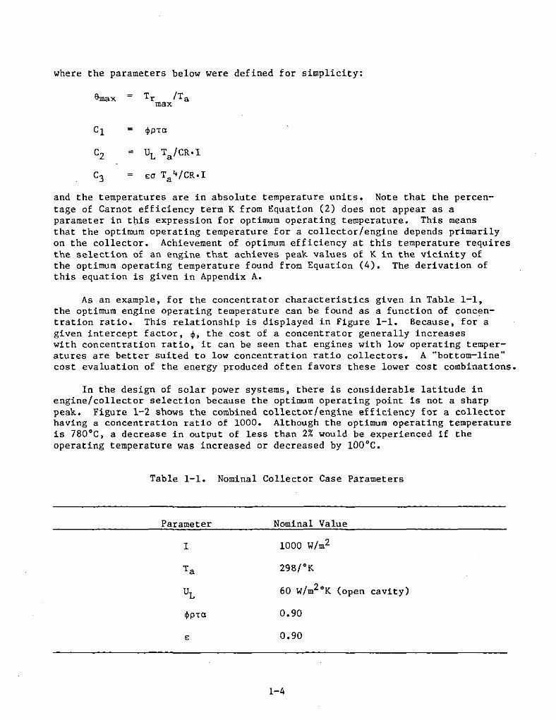
and the temperatures are in absolute temperature units. Note that the percentage of Carnot efficiency term K from Equation (2) does not appear as aparameter in this expression for optimum operating temperature. This meansthat the optimum operating temperature for a collector/engine depends primarilyon the collector. Achievement of optimum efficiency at this temperature requiresthe selection of an engine that achieves peak values of K in the vicinity ofthe optimum operating temperature found from Equation (4). The derivation ofthis equation is given in Appendix A.
As an example, for the concentrator characteristics given in Table 1-1,the optimum engine operating temperature can be found as a function of concentration ratio. This relationship is displayed in Figure 1-1. Because, for agiven intercept factor, ~, the cost of a concentrator generally increaseswith concentration ratio, it can be seen that engines with low operating temperatures are better suited to low concentration ratio collectors. A ··bottom-line"cost evaluation of the energy produced often favors these lower cost combinations.
In the design of solar power systems, there is considerable latitude inengine/collector selection because the optimum operating point is not a sharppeak. Figure 1-2 shows the combined collector/engine efficiency for a collectorhaving a concentration ratio of 1000. Although the optimum operating temperatureis 7BO°C, a decrease in output of less than 2% would be experienced if theoperating temperature was increased or decreased by 100°C.
Table 1-1. Nominal Collector Case Parameters
Parameter Nominal Value
I 1000 W/m2
Ta 29B/oK
UL 60 W/m2°K (open cavity)
~PTCI 0.90
E 0.90
1-4

1200...------------------------------,
1000
u0 -W0<:::J 800I-
~W0-
::E
/wl-
t'Z 600 /l- #'~w ~0-
~0::E:::J 400::EI-0-
0
200
oL-----S..LO-O----=-10J.,.0."..0----1..JSO-0-----20..J.O-0----2....JSOO
GEOMETRIC CONCENTRATION RATIO
Figure 1-1. Optimum Operating Temperature for the Collector Defined inTable 1-1 Operating in Combination with an Engine
1-5

100
GEOMETRIC CONCENTRATIONRATIO = 1000
COL80 LEcro
R Ef:f:ICIEIycy
>R 600
CzwUu.. ENGINE EFFICIENCYu.. 40w
COMBINED EFFICIENCY
OPTIMUM
20 OPERATINGPOINT
o400 600 800 1000 1200 1400
OPERATING TEMPERAlURE, °c
Figure 1-2. Collector and Engine Efficiency Variation withOperating Temperature for a Collector Having aGeometric Concentration Ratio of 1000
1-6

C. OTHER CONSIDERATIONS
In addition to these two primary considerations there are other factorsspecific to solar applications that must be considered when selecting anengine for solar application. One of the most important is that the enginemust be designed for external heat addition to the working fluid. This heatingusually takes place in a solar receiver. This is more easily done withRankine-, Brayton-, and Stirling-cycle engines than with Otto- or Diesel-cycleengines.
Because insolation varies during the operating period, the engine controlsystem must be able to respond to variable heat input while maintaining aconstant engine speed. For many proposed applications, both the heat in andthe load will vary while a synchronous alternator maintains a constant enginespeed. Special control system modifications are required to handle thesevariations for some engine designs.
The rated power output of engines currently of interest to the solar dishprogram is between 10 and 100 kW. This range is based on the size ofthe solar power dishes currently envisioned, i.e., between 5 and 20 m indiameter. The mass and volume of the engine should be small enough to keep thecost of engine supporting structure at a minimum and to minimize blockage ofincoming solar radiation.
Finally, an engine used in solar power applications must have a long servicelife and low O&M costs. Engines used in solar applications should have lifetimesapproximately ten times longer than automotive engines; the latter are typicallydesigned for lifetimes of about 5000 hours with periodic maintenance every 500hours.
1-7


SECTION II
SURVEY
In order to assess the development status of engines in the lO-to-lOO-kWpower output range, survey letters were sent to 39 companies. These companieswere chosen because of their known past involvement in designing externallyheated engines in the appropriate power and efficiency range. The list ofaddressees given in Appendix B was compiled after discussions with JPL personnelinvolved with engine procurement. The individual noted as the contact was theperson who responded to the survey. The engine data report and cover letterare included as Appendix C. The survey requests technical information on theengine cycle in addition to information on maintenance, production, and modification of the engine and on the manufacturer's capabilities. Because informationwas being sought on developmental projects, it was decided to emphasize responsesto the technical data outlined on the first page of the attached data report form.
In the cover letter, it was noted that the information provided wouldonly be used internally by the Jet Propulsion Laboratory (JPL) in order toprotect those companies responding with proprietary data. However, as responseswere received, it became apparent that most of the information was for generaldistribution. Because of the transition in management of the parabolic dishprogram from JPL to Sandia National Laboratories-Albuquerque, each respondentwas asked if their data could be made generally available; affirmative replieswere received in all cases.
2-1


SECTION III
RESPONSE SUMMARY
Most of the 39 companies which received a survey form have responded eitherwith pertinent engine data or an indication that they are not involved in anyappro~riate projects. No response was assumed to mean either that no appropriateprojects existed within the company or that information on engine developmentprojects could not be made available. This was confirmed by telephone in mostcases; a follow-up letter was sent to companies located outside the United States.
Brief descriptions of the engine development projects found in thissurvey are given below. Table 3-1 summarizes the findings in a format enablingcomparison among engines. The two most important parameters for solar applications, cycle efficiency and peak operating temperature, are presented graphically in Figure 3-1.
A. BRAYTON CYCLES
1. Allison
The Allison Gas Turbine Operations Division of General Motors inIndianapolis, Indiana, is developing a small, high efficiency gas turbine, knownas the AGT 100, for automotive applications. This program parallels the GarrettTurbine development of the AGT 101. The engine consists of a single-stagecentrifugal compressor and a radial turbine with a rotary ceramic regenerator.At a design turbine inlet temperature of 1288°C (2350°F) the engine produces 75kW of power at an efficiency of 43%. The second of these engines is currentlybeing built.
2. Garrett AiResearch
The Garrett AiResearch Corporation in Torrance, California, produces asubatmospheric Brayton-cycle engine that has been converted for operation on asolar concentrator. The cycle is regenerative, with heat addition occurring atatmospheric pressure and heat rejection at approximately one-half an atmosphere.It is a closed cycle using air as the working fluid. When operating with aturbine inlet temperature of 871 0 e (1600°F), the engine will produce 11 kW ofelectricity at 27% thermal efficiency. These engines are also being proposedas part of a gas-fired heat pump system, and six have been built and tested todate.
3. Garrett Turbine
Garrett Turbine Engine Company in Phoenix, Arizona, is developing asolar version of their ceramic-component automotive Brayton-cycle engine (theAGT 101). It incorporates a centrifugal compressor and turbine and a ceramicrotary regenerator. Operating with a turbine inlet temperature of 1371 0 C(2500°F), the engine will produce 75 kW of shaft power at an efficiency of 47%.
3-1

A prototype engine using metallic rather than ceramic parts has been built andtested. The ceramic components are currently undergoing development testing.
4. Microturbo
Microturbo S. A. of Toulouse, France, manufactures a line of small gasturbine engines used for ground and aircraft auxiliary power units. A typicalengine, the recuperated Gevandan 9, Model 2R, incorporates a centrifugal compressor, a radial turbine, and a cross-flow regenerator. Operating with aturbine inlet temperature of 750°C (1382°F), the engine will produce 80 kW ofshaft output at an efficiency of 18%. Many of these engines have been made andincorporated into military applications.
5. Solar International (Turbomach)
Solar International of San Diego, California, builds a line of smallgas turbine engines used for auxiliary power units and other power applications.Two of their engines, the Gemini and the Titan, are in the power range appropriatefor solar dish applications. Both use centrifugal compressors and radial turbines and do not incorporate regeneration. The Gemini will produce a maximumpower of 21 kW(shaft) operating at an efficiency of 8.7%. The Titan produces67 kW of power at a similar thermal efficiency. Many of these engines have beenbuilt and are in service throughout the world.
B. RANKINE CYCLES
1. Barber-Nichols
The Barber-Nichols Engineering Company of Arvada, Colorado, has builtan organic Rankine-cycle engine that has been tested on a solar concentrator.The engine consists of a centrifugal pump, a turbine, and a permanent magnetalternator on a single shaft. The working fluid is toluene, which reaches amaximum temperature of 400°C (752°F) when producing 20 kW of electricity at athermal efficiency of 23%. Regeneration is included in the cycle, and heat isrejected to the atmosphere by a fan-cooled condenser.
2. Bertin et Cie
Bertin et Cie in Plaisir, France, has developed an organic Rankinecycle which uses Fluorinert as the working fluid. Operating at a maximumtemperature of 250°C (482°F), the engine.produces 50 kW of electrical power.Although no cycle efficiency information was given, the turbine operates at112 Hz (6720 rev/min) with a turbine efficiency of 78%. This engine is inthe prototype development stage for use in solar or waste heat recoveryapplications.
3-2

100
•
® SUBATMOSPHERICBRAYTON CYCLE
>Ii.0,
GzUJ
w UIw l.l..
l.l..UJ
UJ--'uG
80
60
40 LARGE W/,0
STEAM WMPOWER PLANTS
~ ®~STIRlING MODEL 4-95
o®
CD G800
TEMPERATURE,oC
1000
SOLARIZEDADVANCED GASTURBINE®
CD
1200 1400
Figure 3-1. Comparison of Maximum Cycle Temperature and Engine Efficiency for Engines Noted in Table 3-1.(Circled letters correspond to those used for listing engine manufacturers in the table.)

Table 3-1. Summary of
COII1>a01 Engine Cycle Open! Mechanicll Alternator Output I Efficiency Speed, laource, Illink ,Designation Closed " Goal, , H. 'C 'C
.J Sunpower. Inc. 1982 0-2 Stirling C Free piston Linear ". 44 50 710 35
bl SU-rling Tber_l Moton STM4-120RH Stirling C Variable angle Op' • 40 48 46.1 800 45swash plate (45 @ ~X)
oj Bertin et Cie Stirling C Free ptstQn/el..ct. Linear " 50 590 70coupled displacer
" foster-l«11er Simple Cycle Steam Rankine C Reciprocating!crank Opo. 22.4 2Z 30 538 100
.J Foster-Ml11er Compound Reheat Stealll Rankine C Reciprocating Opt. 28.2 " 30 700 100comp./reheat wateractuated valves
f) 8arber-Nichols O'C Organic C Turbo_chine High-speed ZOO 23 1000 400 50tngineering Co. Rankine integral
.) Garrett Turbine SAGT Ceramic Brayton 0 Turbomachlne! Gearbox! 15 47 14'>0 1371 "tngine Co. cer"lIlie rotor b"lt
hJ AiResearch ''''C Brayton C Turbomachine High-speed ll' " 1183 871 I'mag coupled
·Il \Jnited Stirling All 4-95 Stirling C Reciprocatinglcrank Direct 24.4'" 40 30 720 50drive
" United Tech Res. Center Solar Chiller Rankine C Turbomachine Opt. 18.7 " 717 149 45Drive Cycle
k) Allison ACT 100 Brayton 0 Turbo.uchine Op1. " 6l 11)2 1288 "1) Solar International Ge~ni Brayton 0 Turbo_chine Opt. 2l , 15(,5 115 15
.) Sola .. International Titan Brayeon 0 Turbo....chine Opo. 67 , 1021 613 2l
n) !:lutcher Industries Stealll Rankine C Reciprocating Op,. " 21 33.3 593 88
.) 'the[1ll() Electron Bottoming Organic C Turb<I1"",,chine Opt. 35 2l 617 516 21Cycle ~nkille
p) IUcrotu"bo Gevaudan Brayton 0 Turbomachlne Op,. 80 18 838 750 25(France) -9 Hod. "
q) Sundstrand ORC Proposal Rankine C Turbo_chine High-apeed ", 21 667 '" 211ntell'ral
" Hechanical Technology, Inc. 3 kWe FPSE Stirling C Free piston Linear ). " 60 760 52
.) Bertin et Cie 50 kWe ORC Rankine C Turbomachine Opo. 500 78 (turb) 112 250 24
akW(electric)
Legend:ORCSAGTSABC
AGTFPSEOpt.
= organic Rankine cycle= solarized advanced gas turbine= subatmospheric Brayton cycle
automotive advanced gas turbine= free-piston Stirling engine= optional
3-4

Heat Engine Data
Worldng flw pux • Pmin. Pavg • Energy Cooling Regen? 01_oslons. TOUI No. Units Contac.t/PhoneFluid Rate, I<g!1\ MP. '" .,. Source ,. Mass, Itg Built
Helium "A Solar-~flat M. Yo. 44 dis 1l 83 ISO 1 Prototype li11U... T. BealcDllector- (614) 594-2221
Heliull. H/A 11 Sodiu.. heat Water Yo. 30 0114 x 64 75 rtlUll design R. J. Meijerpl,. ph..", (313) 995-1755
Helium H/A 5.5 GaB/solar Water Woven Teat ..... Michel Oanc.ettescreen
Watu 136 .., 0.1 Oil/gas BoUing None 100 18 Roger Dealereondenser (617) 890-]200
Water " 12.8 0.1 Lab boUer Bol11ng Y.. Roger Dealercondenser (617) 890-3200
Toluene 54' 5.' 0.012 SolAr M. Pire 110 dia x 150 390 Bob Olandereondenser tube (0) 421-8111
M. 8.. 0.5 0.1 Solar Ambient Cera1l1c 56 dla 1l 81 190 Co.ponent Dan Kreinerair in rotary teating (602) 231-7090
M. 3" 0.1 0.045 Solar AlIlblent M, 88 dis x 190 36' • George McDonaldair in sheet (21) 512-4519
Helium or HlA 1> Solar \iater \ilre 118 dla x 2(}1 5SO 25 Wortb Petchal
'1 ...h o(}) 549-1114
R-ll 1620 2.2 0.1 Hot water Al. Yo. 45diax61 " Gorken Kelikian(203) 721-1554... 1224 2.2 0.2 Diesel fuel Ambient Ceraalc 58 dia x 56 136 Harold E. ReI,..
air in (l11) 242-5355
M. 1147 0.)6 0.1 )1'-4 Ambient " 25 x )3 x 56 26 ".y Bill Ovenalr in (6111) 238-5754
M. 4915 0.38 0.1 1P-4 Ambient Ho " x 41 x 76 41 "oy Bill Ovenair in (619) 238-5754
Water " 10.3 0.01 Diesel M. Yo. 63x30x69 264 Ted 1. SaithNo. 2 eondenaer (6111) 518-5502
Trlfluoro- 786 '.8 0.1 E:o:b. gaa M. 2,. 91 x 152 x 91 228 3 Mik. Kaplowethanol! (611) 8110-8700water
M. 3060 0.)3 0.1 11'-4 Ambient Y.. 41 dia x 77 55 "oy Herb J. Sagendorfair in (516) 567-3780
Toluene 817 4.5 0.009 Solar M. 2,. 81 dia x 120 29. Coaponent Doug Laeeyteating (815) 226-7991
Heliua H/A Nat. g.. Water Yo. " • 61 ... '" Prototypes George Dochat(S18) 785-2242
Fluorinert 5256 l.l 0.007 Rt. trans. Water Prototype A. Verne8Ufluid (3) 056 25 00
3-5

3. Dutcher Industries
Dutcher Industries of San Diego, California, has developed a smallsteam engine as part of the California and U.S. automotive steam engine development program. Distilled water is the working fluid for this closed double-expansion reheat/regenerative cycle. With steam at 10.3 MPa (1494 psia) and593°C (1099°F), the engine is designed to produce 40 kW shaft output at anefficiency of 27%. One prototype had been tested, with a second engine havingbeen partially fabricated, before program funding stopped.
4. Foster-Miller
Foster-Miller ASSociates of Waltham, Massachusetts, is developing tworeciprocating steam Rankine-cycle engines. One, a single-piston, simple cycleproduces 22.4 kW of power at an efficiency of 22% with superheated steam atS38°C/6.9 MPa (lOOO°F/lOOO psia). A compound reheat version produces 28.2 kWat an efficiency of 36% when supplied with superheated steam at 700°C/12.8 MPa(1292°F/18S6 psia). This second engine incorporates reheat between the highpressure and the low-pressure cylinders, a regenerator, and water-actuatedvalves. Eighteen of the single-cylinder engines have been built and tested, andone compound reheat cycle engine is currently undergoing test.
5. S.P.S.
S.P.S., Inc., of Miami, Florida, produces a line of organic Rankinecycles in the power range of 10 to 400 kW. Freon working fluids are used,with power being produced by a rotary screw expander. These engines operatefrom hot water or steam at 66°C (151°F) or higher as long as the cooling water is55°C (100°F) cooler. For a source temperature of 100°C (212°F), the efficiencyof the cycle is 15%. A number of these units have been produced and sold toforeign countries. Because of the low operating temperature, these units aretoo large and inefficient to be considered for parabolic dish applications and,therefore, are not included in Table 3-1.
6. Sundstrand
Sundstrand Energy Systems of Rockford, Illinois, proposed an organicRankine cycle to be developed for the solar dish program from their previousorganic Rankine-cycle design experience. The proposed engine combined an axialflow turbine, a high-speed alternator, and Pitot pump as a single rotating unit.Vsing toluene as a working fluid, the engine was designed to produce 22 kW ofelectricity at a design efficiency of 27% when operating at 427°C (800°F). Thedesign included regeneration with an air-cooled condenser surrounding the unit.
3-6

7. Thermo Electron
Thermo Electron Corporation of Waltham, Massachusetts, is developinga Rankine cycle for waste heat recovery applications. The engine consists ofan axial turbine expander along with boiler, pump, and condenser. The workingfluid is a mixture of trifluoroethanol and distilled water that when heatedto 516°C, will produce a 35 kW shaft power with an efficiency goal of 25%.Three of these engines have been built and tested.
8. United Technologies Research Center
The United Technologies Research Center, located in East Hartford,Connecticut, has developed a small Rankine power cycle that utilizes solarproduced hot water to drive the compressor of a solar chiller. Decoupled, itcould be used to drive a generator at the focus of a parabolic dish. Theengine incorporates a centrifugal compressor and a radial turbine with a heatexchange boiler. The working fluid is R-ll, which reaches a maximum temperatureof 149°C (300°F) when producing 18.7 kW (25 hp) of shaft power at 24% thermalefficiency. The cycle incorporates a regenerator, and the condenser is aircooled.
C. STIRLING CYCLES
1. Bertin et Cie
Bertin et Cie, located in Plaisir, France, is developing a 3-kWtest model of a free-piston Stirling engine with a linear electric generator onthe power piston and a linear motor on the displacer for control of the phaseangle. Although this size is outside the range of this study, information isincluded because of the engine's scale-up potential. The engine is a hermeticallysealed unit opeating at 50 Hz, with helium at 3.7 to 5.5 MPa (537 to 798 psia)as the working fluid. The design operating temperature is 590°C (1094°F) witha sink temperature of 70°C (158°F).
2. Mechanical Technology, Incorporated
Mechanical Technology, Incorporated (M.T.I.), located in Latham,New York, has under development a 3-kW(electric) free-piston Stirling enginefor small power applications. Although this particular engine is too small tofit solar application requirements, it is included because of its developmentpotential. The engine incorporates a linear alternator and oscillates at 60 Hz.Operating at a high temperature of 760°C (1400°F), the engine has a thermalefficiency of 24% using helium at 6 MPa (870 psia) as the working fluid.Currently, there are prototype engines of this design operating with a naturalgas burner as the heat source.
3-7

3. Stirling Thermal Motors
Stirling Thermal Motors of Ann Arbor, Michigan, under licensing agreements with Phillips (Sweden), is developing a 40-kW kinematic Stirling engine.The engine is a four-cylinder, double-acting configuration incorporating avariable angle swash plate drive. The working fluid is helium at 11 MPa (1595psia), which is heated to 800°C (1472°F) by a sodium heat pipe transfer unit.The predicted efficiency at this operating condition is 48%. The final designof the prototype engine has been completed and the major castings made. Fabrication and testing of the prototype of this engine will be completed whenfunding is obtained.
4. Sunpower
Sunpower, Inc., in Athens, Ohio, is developing a free-piston Stirlingengine connected to a linear alternator. The engine has an electrical outputof 10 kW with an efficiency goal of 44%. The working fluid is helium at 2 MPa(290 psia) with a maximum cycle temperature of 710°C (1310°F). One prototypeengine of this size has been built and tested.
5. United Stirling
United Stirling of Malmo, Sweden, produces a four-cylinder, crankshaftdrive reciprocating Stirling engine, which has been tested on a solar concentrator.The working fluid can be either helium or hydrogen with power output controlledby gas pressure. At a mean pressure of 15 MPa (2175 psia), the engine willgenerate 24.4 kW of electricity at an efficiency of 40% when heated to 720°C(1328°F). Twenty-five of these engines have been produced and are undergoingtesting for various applications. A 55- to 60-kW version of this engine isunder development for a Messerschmitt-Boelkow-Blohm dish system in Saudi Arabia.
3-8

SECTION IV
CONCLUSIONS
From a survey of 39 engine manufacturers, a list was compiled of 19 engines(in the 10-to-l00-kW range using either Brayton, Rankine, or Stirling cycles)that employ external heat addition and, therefore, are potentially applicablefor parabolic dish-electric modules. Many companies responding to the surveyare not listed in Section III because their engines were not applicable forsolar power generation or their interest in development of these engines hadceased.
It was observed that, because of the dominance of Otto- and Diesel-cycleengines involving internal combustion/heat addition, few applicable externalheat-addition engines exist in the size range considered. Many manufacturersof Brayton and Rankine engines indicated that the size of their engine line waslarger than 100 kW power output. Several Stirling engine manufacturers, onthe other hand, are developing engines smaller than 10 kW.
From discussions with many of the manufacturers, it was found that duringthe 1970's, there was considerable interest in developing new engines in the10-to-l00-kW range both for automotive applications and solar energy conversion.Several companies, who had initiated small engine development programs duringthat time, have dropped further development due to reduced federal funding forsolar and automotive engine technology development.
It appears from the survey that the technology exists to produce externalheat-addition engines of appropriate size with thermal efficiencies of over 40%.Developmental problem areas seem to be materials and sealing. High efficiencyBrayton-cycle engines must operate at 1000 to 1400°C, where most materials losetheir strength. High efficiency kinematic Stirling-cycle engines can attainan efficiency of 40% at temperatures in the range of 700 to BOO°C, with sealingand component thermal cycling proving to be the significant problem areas.Rankine cycles operate at even lower temperatures with lower efficiencies;with this engine cycle, the goal is to design efficient, multi-stage expansionturbines for the power output associated with solar applications.
All of the engines listed in Table 3-1 are of a developmental nature havinglittle, if any, operating experience. Because O&M costs will be an importantfactor in determining the cost effectiveness of parablic dish solar thermalpower systems (Section I), it is necessary to gain operating experience thatwill provide this cost data. Furthermore, the possibilities of exploringdesign modifications to reduce O&M costs for solar applications can probably bemore economically addressed in the development stage. Thus, it appears thatthe parabolic dish program can benefit from close interaction with the differentengine development programs identified in this survey.
It is concluded that high efficiency engines can be developed for solarparabolic dish applications. Prototypes and limited production models arecurrently in operation. Because one specific engine or engine type does notemerge from this survey as being dominant for solar applications, it appearsthat additional developmental effort should be expended on a range of differentengine options. The availability of different engine options will permitgreater flexibility in matching dish systems to application requirements and inproviding competitive sources.
4-1


APPENDIX A
DERIVATION OF EQUATION (4)
Overall efficiency of a solar power system is:
o = oe Os
Combining Equations (2) and (3) and letting TH = Tr and TL = Ta :
e;a(T It T It)]_ r - aCR·I
Define:
e
CI ~pTC'
C2UL Ta
CR·I
£oT 1+C3 a
CR·I
then,
Taking the derivative with respect to e :
and to find the inflection point (optimum 0 with respect to e) and calling thistemperature 8max ;
_ C2 + C I + C2 + C3
e~ax
Simplifying, we get:
3~ax -"4 e:tax
which is Equation (4).
C+ -2. e&ax =
4C3
A-I


Manufacturer
AFI Energy Systems110 S. Orange Ave.Livingston, NJ 07039
Arthur D. Little, Inc.20 Acorn ParkCambridge, MA 02140
Barber-Nichols Engineering Co.6325 W. 55th St.Arvada, CO 80002
Detroit Diesel Allison Div.General Motors Corp.13400 W. Outer Dr.Detroit, MI 48228
Dornier System GmbH7997 ImmenstaadWest Germany
Dutcher Industries7564 Trade St.San Diego, CA 92121
Energy Research and GenerationLowell & 57th St.Oakland, CA 94608
Energy Technology, Inc.4914 E. l54th St.Cleveland, OH 44128
Foster-Miller Assoc., Inc.350 Second Ave.Waltham, MA 02154
Garrett AiResearch Mfg. Co.9851 Sepulveda Blvd.Los Angeles, CA 90009
Garrett Turbine Engine Co.III S. 34th St.Phoenix, AZ 85010
General Electric Co.Aircraft Engine GroupOne Neuman WayCincinnatti, OH 45215
APPENDIX B
ADDRESS LIST
Contact
Robert H. Sawyer(201) 533-2091
Peter Teagan(617) 864-5770
Bob Olander(03) 421-8111
Gene Helms(317) 242-5355
Dr. Lippmann(07545) 8-3440U.S. Rep. (213) 681-3491
Ted Smith(619) 578-5502
Dr. Benson(415) 658-9785
John Martin(216) 587-0555
Roger L. Demler(710) 324-1468
Ray Rockey(602) 231-2679
M. C. Hamsworth
B-1

Manufacturer
General Electric Co.Advanced Energy' Programs501 Allendale RoadKing of Prussia, PA 19406
Hamilton Standard Div.United Technologies Corp.Bradley International AirportWindsor Locks, CT 06096
Jay Carter EnterprisesRoute 1 Box 405ABurkburnett, TX 76354
Kawasaki Heavy Industries Ltd.Seagram Bldg, Room 3309375 Park Ave.New York, NY 10022
Lucas-France11 Rue Lord-Byron75008 ParisFrance
M.A.N. werk, AugsburgStadtbachstrasse 18900 AugsburgWest Germany
Mechanical Technology, Inc.Energy Systems Division968 Albany-Shaker Rd.Lathan, NY 12110
Messerschmitt-Boelkow-Blohm GmbHSpace DivisionPostfach 8011698000 Munchen 80West Germany
MicroturboChem. du Pont-de-RupeBP 208931089 Toulouse CedexFrance
North American Turbine Corp.P.O. Box 40510Houston, TX 77040
Ormat Systems, Inc.98 South StreetHopkinton, MA 01748
Contact
Robert Tharpe(215) 962-5665
Don Phillips(203) 623-1621
Jay Carter, Sr.(817) 569-2238
Mr. Ono(212) 759-4950
i.V. Siemer and i.A. Jenke
Bruce Goldwater(518) 785-2211
Helmut Hopmann(089) 6000 5521
Herb Sagendorf (U.S. Rep)(516) 567-3780
Mr. Fairbanks(713) 466-6200
Nicholas Christopher(617) 653-6300
B-2

Manufacturer
Pratt & Whitney Aircraft GroupUnited Technologies ~orp.
400 Main St.East Hartford, CT 06108
Rolls Royce Ltd.Sales Engineering DivisionPO Box 31Darby DE28BJEngland
SOFRETES MenginZ.1. G'AmillyBP 16345200 MontargisFrance
S.P.S. Inc.P.O. Box 380006Miami, FL 33138
Societe Bertin et CieBP 378373 Plaisir CedexFrance
Societe E.C .A.17 Av. du Chateau92190 MendonFrance
Solar Turbines InternationalP.O. Box 80966San Diego, CA 92138
Stirling Power Systems Corp.7101 Jackson Rd.Ann Arbor, HI 48103
Stirling Thermal Motors2841 BoardwalkAnn Arbor, MI 48104
Sundstrand Energy Systems4747 Harrison Ave.Rockford, IL 61101
Sunpower, Inc.6 Byard St.Athens, OH 45701
Contact
Mr. Mendleson(203) 565-4321
J. A. J. ReesDerby (0332) 42424 Ext. 157
Victor S. Warminger(305) 754-776
P. TarbosM. Dancette
Bill Owen(619) 238-5754
Lennart Johansson(313) 665-6767
R. J. Meijer(313) 995-1755
Mr. Bates(815) 226-6000
William Beale(614) 594-2221
B-3

Manufacturer
Thermo Electron Corp.101 First Ave.Waltham, MA 02154
United Stirling, Inc.211 The StrandAlexandria, VA 22314
United Stirling (Sweden) AB & Co.Box 856S20l80, MalmoSweden
United Turbine (Sweden) ABM. Grangesbgsg 18MalmoSweden
Williams Research Corp.2280 W. Maple Rd.Walled Lake, MI 48088
Alpha United, Inc.P. O. Box 847El Segundo, CA 90245
Sanders Associates95 Canal StreetNashua, NH 03060
Pratt & WhitneyCanada
United Technologies Research CenterSilver LaneEast Hartford, CT 06108
Ricardo Consulting EngineersBridgeWorksShoreham-by-SeaWest Sussex BN45FGEngland
Contact
Mike Koplow(617) 890-8700
Worth Percival(703) 549-7174
William Bower(313) 624-5200
Don Elbert(213) 322-9570
Bear Davis(603) 885-4321
Colin B. Wrong(514) 647-7584
Gorken Melikian(203) 727-7000
B-4

APPENDIX C
DATA REPORT AND COVER LETTER
C-l

•JET PROPULSION LABORATORY California InMitutl' of Technolo!?y. 4800 Oak Groue Drive. Pasadena, California 91109
July 18, 1983
Refer to 34l-WBS:gg
Attention: Chief Engineer's Office
Dear Sirs,
Jet Propulsion Laboratory has an interest in low-cost, high-performanceheat engines with power outputs in the 10 to 100 kW range for application toparabolic dish solar power systems. We are surveying engine manufacturers toascertain whether there are advanced heat engines on the horizon which wouldenhance the economic viability of the production of electricity from solarenergy.
In a typical application, the engine is placed at the focus of a parabolicdish solar energy concentrator. Concentrated solar flux heats the engine'sworking fluid, operating the engine and driving an alternator. Low-temperatureheat is typically rejected at the engine to eliminate the necessity of fluidtransport to the ground.
The parameters which govern the design of dish power systems are, in theirorder of importance,
a) thermal conversion efficiency,
b) operation and maintenance cost,
c) capital cost of unit.
The application source temperature can be as high as needed with materialscapability being the limiting factor.
The current technology with which we are working has the parameters listedin Table 1. It is the purpose of this study to identify developed or partiallydeveloped engines in the 10 to 100 kW output range that are suitable for parabolic
Telephone (213) 354-4321 Twx 910-588-3269C-3
Twx 910-588-3294 Telex 67-5429

-2- July 18, 1983
dish power systems. In addition, it is important to ascertain the probable timingof commercialization and the probability of sales for other than solar applicationssince the initial solar market is not envisioned to be large.
Attached is a questionnaire indicating the information needed on any advancedengine you believe may be applicable to the solar dish program. I will contactyou by telephone in about a week to discuss candidate engines and will transcribethe appropriate data at that time. If you prefer, you may fill out the attachedquestionnaire ahead of time and return it to me at the following address:
Dr. William (Bill) StineJet Propulsion Laboratory
Mail Stop 507/2284800 Oak Grove Drive
Pasadena, CA 91109
Realizing the sensitivity of the type of data which we are requesting, thequestionnaire will be marked for JPL internal use only. The information isto be used only for JPL studies and will not be disclosed to outside· parties.
Will you please reply indicating the appropriate person to contact forthis information.
Sincerely,
William B. Stine, Ph.D.
Attachment
cc: AFI Energy SystemsArthur D. LittleBarber-Nichols EngineeringDetroit Diesel AllisonDornier Systems GmbHDutcher IndustriesEnergy Research & GenerationEnergy Technology Inc.Foster-Hiller Assoc.Garrett AiResearch Mfg.Garrett Turbine EngineGE - Valley ForgeHamilton StandardJay Carter EnterprisesKawasaki Heavy Ind.Lucas-FranceM.A.N. Werk, AugsburgMechanical Technology, Inc.M.B.B. GmbHMicroturbo
C-4
North American TurbineOrmat SystemsPratt & WhitneyRolls Royce LtdSOFRETES MenginSPS Inc.Societe Bertin et CieSociete E.C.A.Solar Turbines InternationalStirling Power SystemsStirling Thermal MotorsSundstrand Energy SystemsSunpowerThermo ElectronUnited StirlingUnited TurbineWilliams Research

TABLE 1
PERFORMANCE AND COST PARAMETERS OF CURRENTLY AVAILABLE ENGINES APPLICABLE
TO PARABOLIC DISH SOLAR POWER SYSTEMS
Engine Engine Brake Maximum Fraction Capital O&MType Efficiency Temperature of Carnot Type* Cost** Costs
TRankine - organic 23% 400°C .41 T
TurbineBrayton 32% 815°C .44 T Approx. Machinery
()$200 $300/eng/yr
I per KwV>
Brayton - ceramic 41% 1149°C .52 T
KinematicBrayton - subatmospheric 27% 871°C .37 T Machinery
$860/eng/yr
Stirling 40% 720°C .57 K I
*T - Turbomachinery K - Kinematic
**Based on 100,000 cumulative, 25,000 units/year (1981 dollars)


POWER CONVERSION UNIT PERTINENT DATA REPORT
Note: This report is to be completed by the appropriate JPL employee duringand after telecon or personal interview with each manufacturer'srepresentative(s).
Report Prepared By: .Section~ _
Engine Thermodynamic Cycle Engine Mechanical Arrangement
Closed
Open
Manuf actu rer
Name
Location
Telephone No.
RankineStirlingBraytonOther
RotatingCompressor ExpanderCentrifugal TurbineAxial VaneVane LobeLobe ScrewOther Other
Reciprocating
CrankSwash PlateFree PistonOther
Person( s) Contacted _
Engine Performance
Design Specifications
Shaft Power Output kW or HPShaft speed rpm or HzEnergy Source(s) for
Current EngineSource Temperature of or °cSink Temperature of or °cThermodynamic MediumFlow rate of medium Ibmfs or kg/sMean Effective Operating
lbf/in2Pressure: or MPaMaximum Cycle Pressure Ibf/in2 or MFaMinimum Cycle Pressure lbf/in2 or MPa
C-7

THERMODYNAMIC CYCLEWITH STATE POINTSDEFINED
Notes:
Present experimentalresults whereverpossible.
Define coordinates.
Define state pointsas precisely aspossible.
PART-LOADCHARACTERISTICS
Notes:
Present experimentalresults whereverpossible.
Specify form of inputpower, i.e., whetherfull or direct thermal.
Specify form of outputpo~er, i.e., shaft orelectric (AC or DC andvoltage) •
Input Power
C-8

(RMR)
Engine Maintenance Requirements
Mean Time Between Failure (MTBF)
For components failing most frequently
Component
1. _
2.----------------------3. _
4. _
5. _
For the complete engine ~ - - -
Routine Maintenance Requirements
Frequency
Labor
Parts
Facilities (Chargeable to RMR)
Service Equipment (Chargeable to RMR)
Minor Overhaul Requirements (MoOR)
Frequency
Labor
Parts
Facilities (Chargeable to MnOR)
Service Equipment (Chargeable to MnOR)
Major Overhaul Requirements (MjOR)
Frequency
Labor
Parts
Facilities (Chargeable to MjOR)
Service Equipment (Chargeable to MjOR)
C-9
Hours
___ l/y
___ m.h./y
__ Sly
Sly
___ Sly
___ l/y
___ m.h./y
___ Sly
Sly
Sly
lly
___ m.h./y
Sly
Sly
___ Sly

Production Potential
Production RateRate (UnUs/y)
Current
1985
1990
Producibility
Unit Value at Stated Production RateCost ($/Unit) Price ($/Unit)
. Current (Short discussion, including states of component and complete unitdevelopment, prototype testing, number of units in the field, andcommercial availability)
Potential for Cost Reduction (Short Discussion)
Sources of Funding
Current
Scheduled
Potential
C-10

Adaptability to Solar Systems
Modifications Required for Solarization
Cost for Required Modifications: _
Estimated or Actual?
Collector Requirements
E A (Circle One)
Required Engine Thermal Input at Rated Power kW
Required Receiver Operating Temperature
Power Conditioning Requirements
OF or °c----- ------
Performance and Maintenance Requirements for the Solarized Engine as Comparedwith Those for the Engine in Its Current Form
C-ll

Capabilities of the Manufacturer
Capitalization S
Sales Volume
Current Products
Product
2.
3.
Number of Employees
Factory Floor Space
___________________ Sly
Percent of Total Sales
Note: Refer to the Dunn and Bradstreet and Thomas registers in compiling theabove requested data.
Fraction of personnel currently dedicated to the PCU
Fraction of facilities currently dedicated to the PCU
Related past accomplishments of the manufacturer:
Selling Price of the PCU: Lot Size
1
10
100
1,000
10,000
Selling Price
______ S/Unit
,~u.s. GOVERr-°MEKT PHIKTI:<C OFFICE; 1984-544-063/10383
C-12


SURVEY OF MANUFACTURERS OF HIGH-PERFORMANCE HEAT ENGINES DOEDOE/JPL-1060-75 ADAPTABLE TO SOLAR APPLICATIONS
-r r- _, z mm_._,
_F- 0 _ __- I_'_oprl Z ._z o 3 _
Z--... r" :o. _ c_-.o
3>" --m
I"0 -4
o-.m m g.(.,I--4
__ _0I
"0o
m