
LHC Physics Commissioning - part 1 - Roberto Tenchini INFN - Pisa LHC 2006 Martignano, 12-18 June...
52
LHC Physics Commissioning - part 1 - Roberto Tenchini INFN - Pisa LHC 2006 Martignano, 12-18 June 2006 to: Roger Bailey, Tommaso Boccali, Fabiola Gianotti, Dan Green, Palla, Gigi Rolandi
-
Upload
holly-mckinney -
Category
Documents
-
view
216 -
download
1
Transcript of LHC Physics Commissioning - part 1 - Roberto Tenchini INFN - Pisa LHC 2006 Martignano, 12-18 June...
LHC Physics Commissioning
- part 1 -
Roberto Tenchini
INFN - Pisa
LHC 2006Martignano, 12-18 June 2006
Credits to: Roger Bailey, Tommaso Boccali, Fabiola Gianotti, Dan Green, Fabrizio Palla, Gigi Rolandi
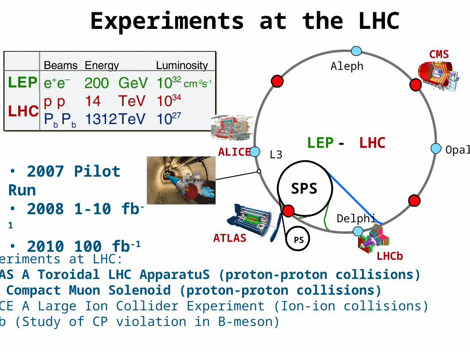
Experiments at the LHC
• 2007 Pilot Run • 2008 1-10 fb-1
• 2010 100 fb-1
Opal
Delphi
SPS
PS
LEP - LHC
Aleph
L3
LHCb
ALICE
CMS
ATLAS
Experiments at LHC:ATLAS A Toroidal LHC ApparatuS (proton-proton collisions)CMS Compact Muon Solenoid (proton-proton collisions)ALICE A Large Ion Collider Experiment (Ion-ion collisions)LHCb (Study of CP violation in B-meson)

LHC cross sections and rates
At Highest Design Luminosity (1034 cm-2 s-1)
SM Higgs (115 GeV/c2): 0.1 Hzt t production: 10 HzW : 102 Hzbb production: 106 Hz
Inelastic: 109 Hz
Beam crossing every 25 ns25 pileup event / beam crossing at High Lumi
These rates will be achieved after a long periodof commissioning & operationIn parallel well understood detectors must be operational to exploit the rich physics
Selective triggers are required
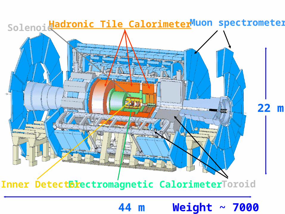
Electromagnetic Calorimeter
Muon spectrometer
Inner Detector
Hadronic Tile CalorimeterSolenoid
Toroid
44 m
22 m
Weight ~ 7000 tons

MUON BARREL
CALORIMETERS
Silicon MicrostripsPixels
ECAL Scintillating PbWO4
Crystals
Cathode Strip Chambers (CSC)Resistive Plate Chambers (RPC)
Drift Tube Chambers (DT)
Resistive Plate Chambers (RPC)
SUPERCONDUCTING
COIL
IRON YOKE
TRACKERs
MUON ENDCAPS
Total weight : 12,500 tOverall diameter : 15 mOverall length : 21.6 mMagnetic field : 4 Tesla
HCAL Plastic scintillator brass
sandwich
The Compact Muon Solenoid (CMS)

ATLAS
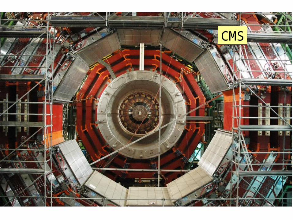
CMS
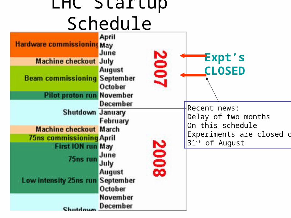
LHC Startup Schedule
Expt’s CLOSED
Recent news:Delay of two monthsOn this scheduleExperiments are closed on 31st of August

Physics Commissioning: two main phases
• Before data taking starts:– Understand and calibrate the detectors with test
beams, cosmics, surveys, B-field measurements, etc.– Prepare software tools: simulation, reconstruction,
calibration and alignment procedures
• With the initial LHC data:– Commission and calibrate in situ detector and trigger
with physics samples– Understand Standard Model physics at 14 TeV– Measure background to New Physics
Prepare the road to discoveries
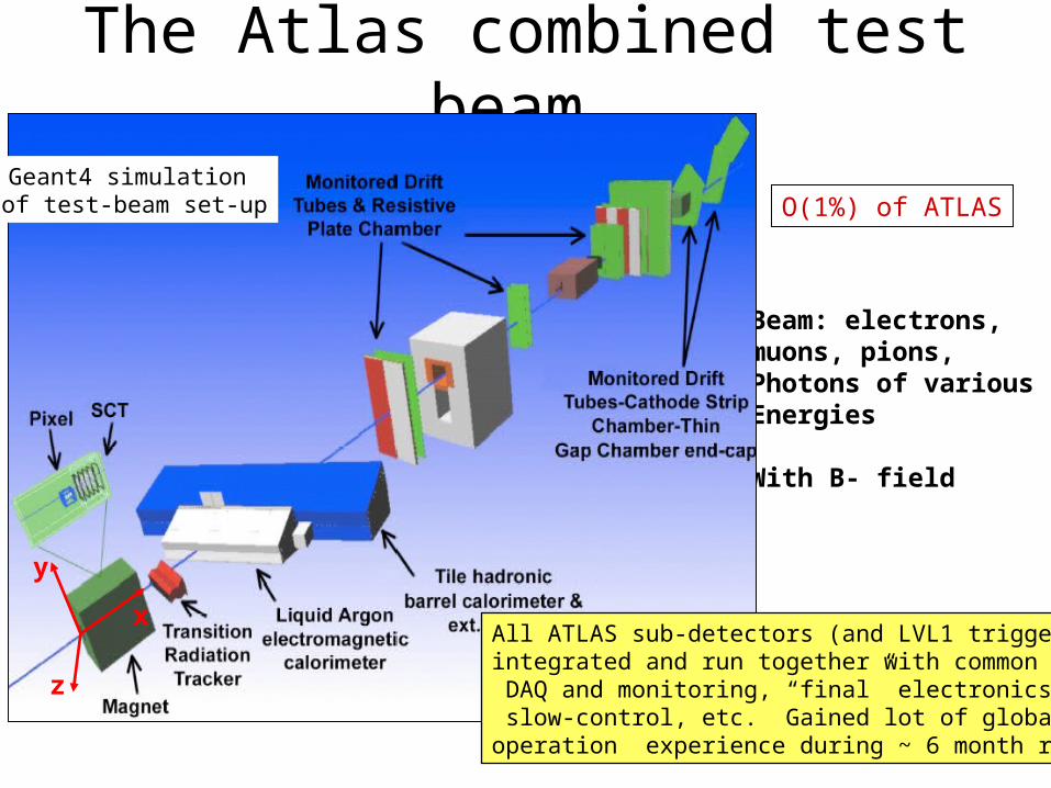
The Atlas combined test beam
Beam: electrons, muons, pions, Photons of variousEnergies
With B- field
x
z
y
Geant4 simulation of test-beam set-up
All ATLAS sub-detectors (and LVL1 trigger) integrated and run together with common DAQ and monitoring, “final” electronics, slow-control, etc. Gained lot of global operation experience during ~ 6 month run.
O(1%) of ATLAS
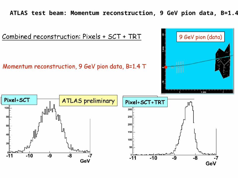
ATLAS test beam: Momentum reconstruction, 9 GeV pion data, B=1.4 T
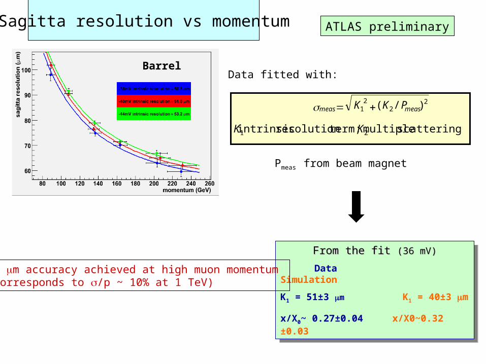
Sagitta resolution vs momentum
Barrel
From the fit From the fit (36 mV)(36 mV)
Data Simulation
K1 = 51±3 m K1 = 40±3 m
x/X0~ 0.27±0.04 x/X0~0.32 ±0.03
From the fit From the fit (36 mV)(36 mV)
Data Simulation
K1 = 51±3 m K1 = 40±3 m
x/X0~ 0.27±0.04 x/X0~0.32 ±0.03
21
22
21
scattering multiple term;resolution intrinsic
)/(
KK
PKK measmeas
Data fitted with:
ATLAS preliminary
Pmeas from beam magnet
50 m accuracy achieved at high muon momentum (corresponds to /p ~ 10% at 1 TeV)
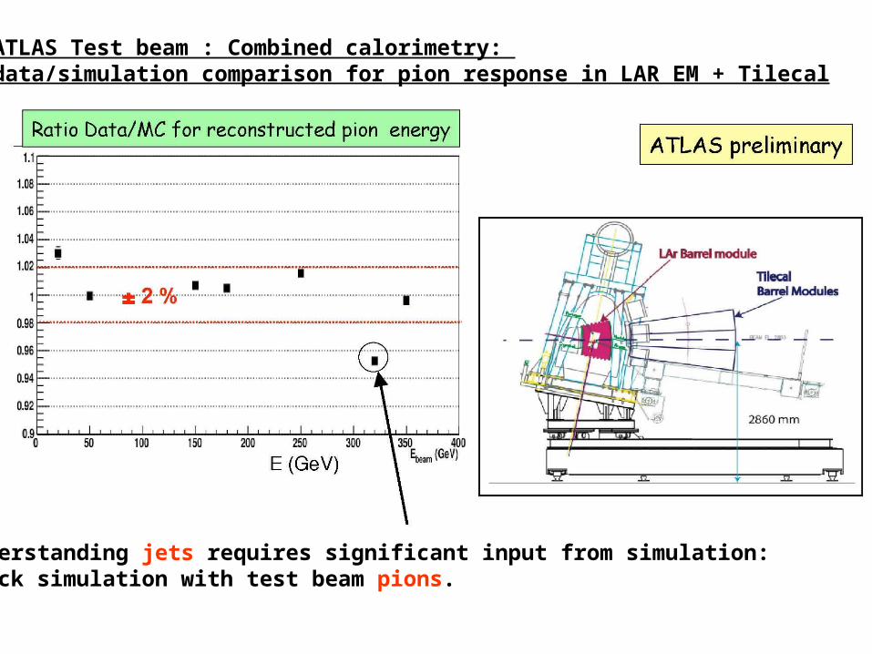
ATLAS Test beam : Combined calorimetry: data/simulation comparison for pion response in LAR EM + Tilecal
Understanding jets requires significant input from simulation:Check simulation with test beam pions.
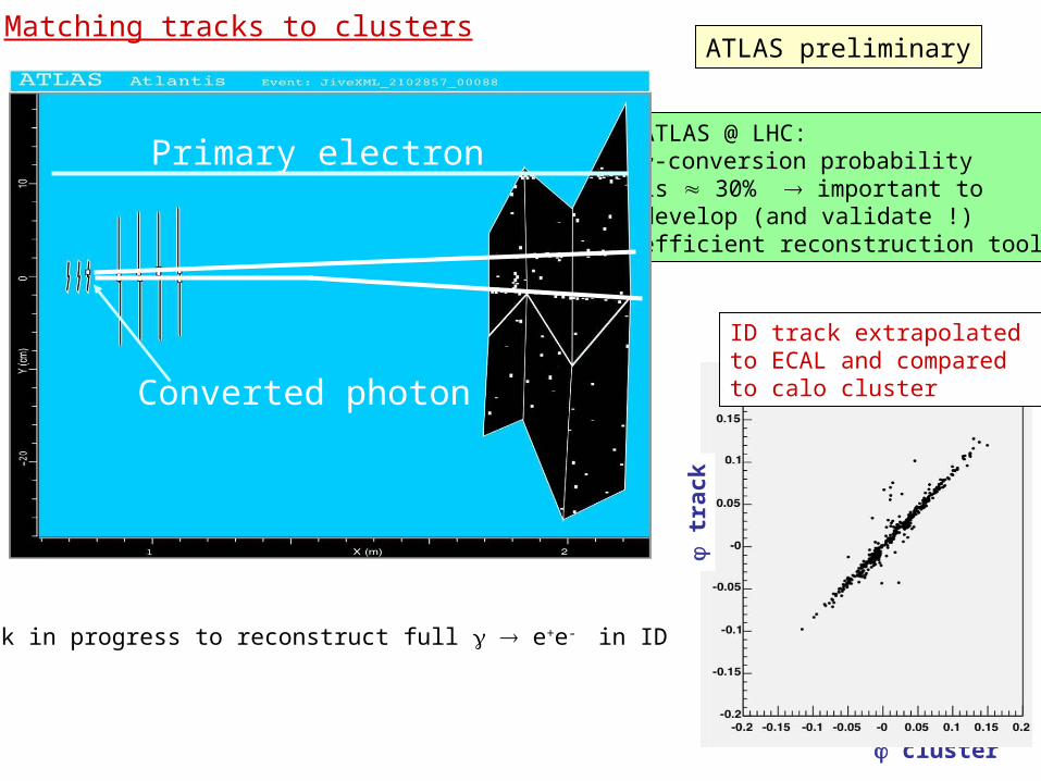
Matching tracks to clustersATLAS preliminary
ATLAS @ LHC: -conversion probability is 30% important to develop (and validate !)efficient reconstruction tools
Work in progress to reconstruct full e+e- in ID
cluster
tr
ack
ID track extrapolated to ECAL and compared to calo clusterConverted photon
Primary electron

CMS: Magnet Test/Cosmic challenge in SX5
Check closure tolerances, movement under field and muon alignment system (endcap + barrel + link to Tracker).
Check installation & cabling of :ECAL/HCAL/Tracker[dummy] inside coil, including cabling test.
Establish stable operation of coil, cryo, power supply and control system. Map the magnetic field.
Check field tolerance of components within and outside the yoke
Test individual and combined operation of subdetectors in ~20o sector of CMS with magnet & central DAQ. Record cosmics. Try out 24/7 operation of CMS. = "cosmic challenge"
CMS closed for magnet test in SX5 surface building: winter 05-06

Commissioning theCMS Magnet
• B-field Mapping • Ramp down to 4.2K ~ 1
month, then 2 months commissioning and 1.5 months of B-field mapping
• To achieve 1% Pt resolution at 100 GeV B/B~0.1%-0.5% (tracker
volume) • (about 1% uniform for
construction) B/B~0.4% calorimeters B/B~1% muon chambers
• How:– Hall probes + NMR

CMS MTCC Overview• End of May: CMS closed
– Commission magnet– Sub-detectors brought up in
separate then combined operation – Alignment system commissioning– A few days of steady magnetic
field at end
• Mid July: reopen + end– Remove Tracker tube, complete
fieldmapper installation/survey– Close up
• End of July: Field mapping through August (Muon and HCAL can continue testing)
• September, lower…Probable mapping points0, 1 (for HI), 2, 3.5,4 Tesla?(Each twice once going up and once coming down for hysteresis
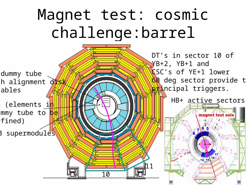
Magnet test: cosmic challenge:barrel
EB supermodules
TK (elements in dummy tube to bedefined)
TK dummy tubewith alignment disk& cables
1011
DT’s in sector 10 ofYB+2, YB+1 andCSC’s of YE+1 lower60 deg sector provide the principal triggers.
HB+ active sectors
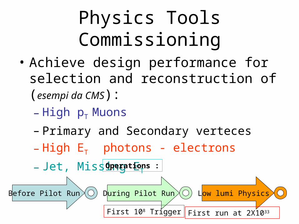
Physics Tools Commissioning
• Achieve design performance for selection and reconstruction of (esempi da CMS):– High pT Muons
– Primary and Secondary verteces
– High ET photons - electrons
– Jet, Missing ET
Before Pilot Run During Pilot Run Low lumi Physics
Operations :
First 108 Trigger First run at 2X1033
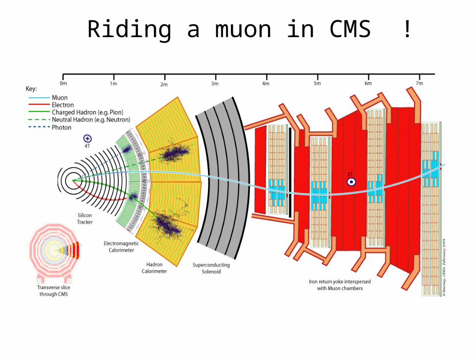
Riding a muon in CMS !
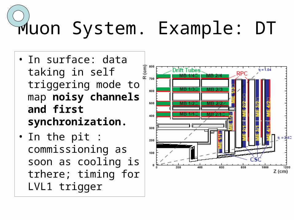
Muon System. Example: DT
• In surface: data taking in self triggering mode to map noisy channels and first synchronization.
• In the pit : commissioning as soon as cooling is trhere; timing for LVL1 trigger
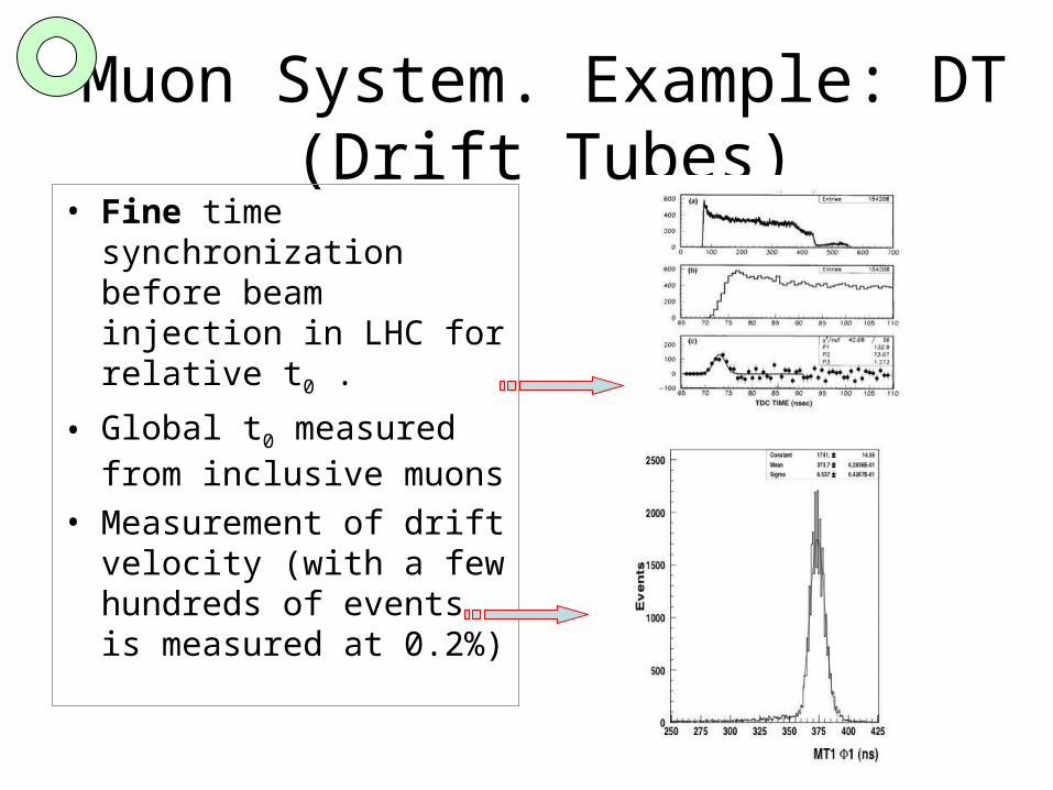
Muon System. Example: DT (Drift Tubes)
• Fine time synchronization before beam injection in LHC for relative t0 .
• Global t0 measured from inclusive muons
• Measurement of drift velocity (with a few hundreds of events is measured at 0.2%)
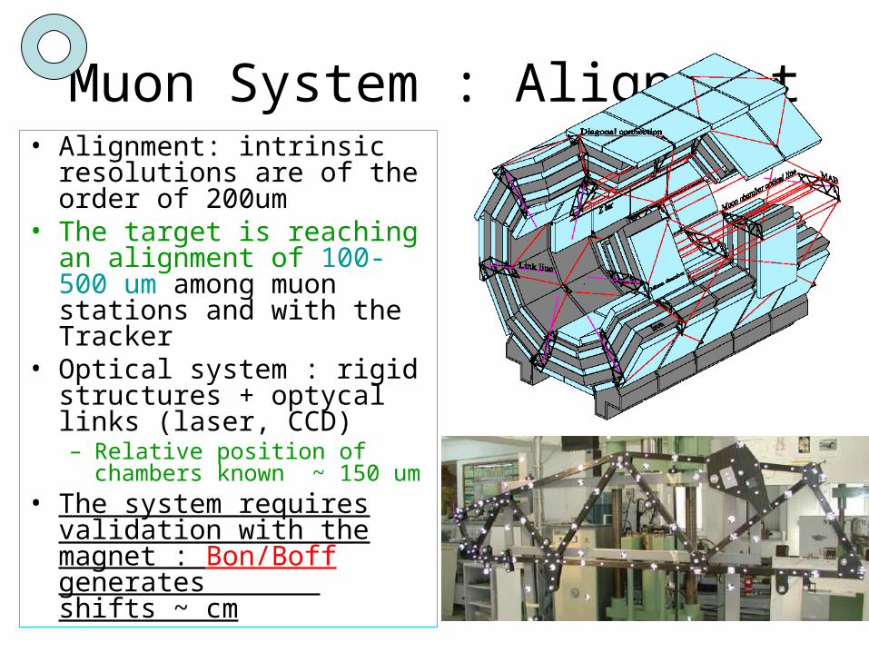
Muon System : Alignment• Alignment: intrinsic
resolutions are of the order of 200um
• The target is reaching an alignment of 100-500 um among muon stations and with the Tracker
• Optical system : rigid structures + optycal links (laser, CCD)– Relative position of chambers
known ~ 150 um• The system requires
validation with the magnet : Bon/Boff generates shifts ~ cm
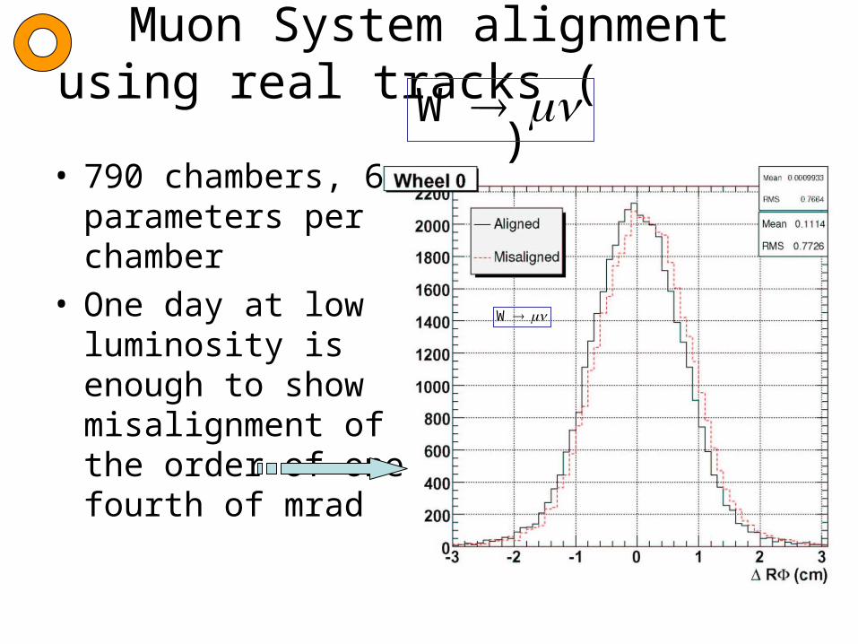
Muon System alignment using real tracks ( )
• 790 chambers, 6 parameters per chamber
• One day at low luminosity is enough to show misalignment of the order of one fourth of mrad
W
W
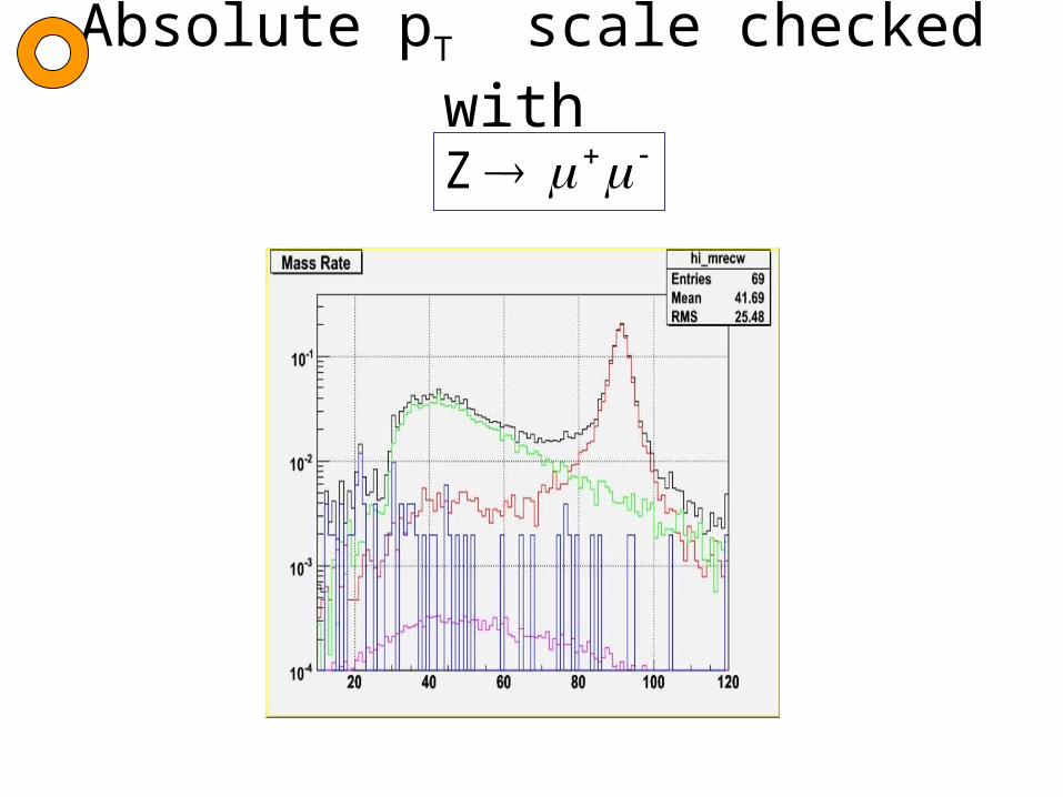
Absolute pT scale checked with Z
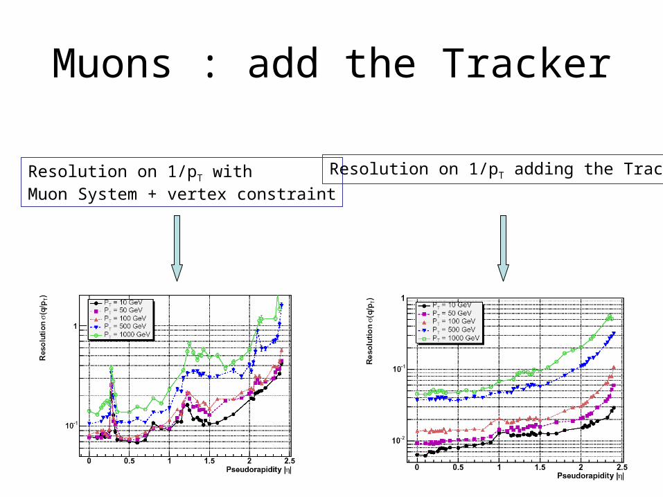
Muons : add the Tracker
Resolution on 1/pT withMuon System + vertex constraint
Resolution on 1/pT adding the Tracker
Tracker Alignment
0
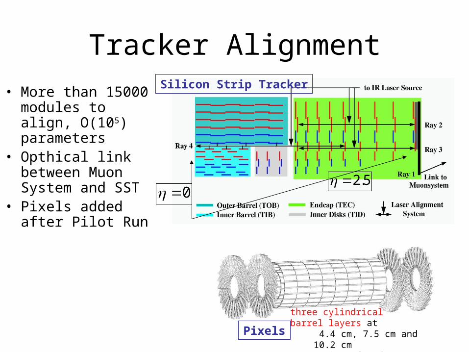
Silicon Strip Tracker
Pixels
5.20
• More than 15000 modules to align, O(105) parameters
• Opthical link between Muon System and SST
• Pixels added after Pilot Run
three cylindrical barrel layers at 4.4 cm, 7.5 cm and 10.2 cm
two pairs of end-cap disks at |z| = 34.5 cm and 46.5 cm up t
Tracker Alignment
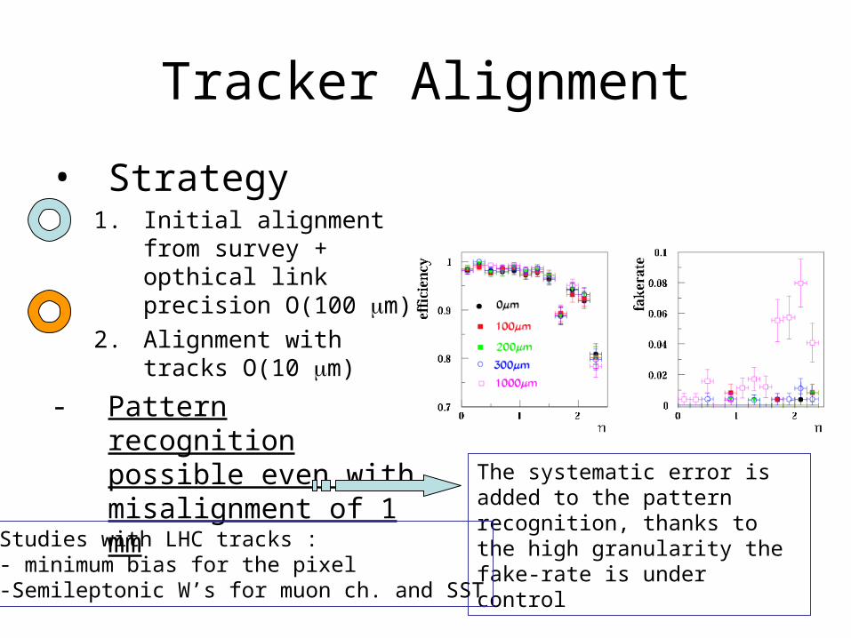
• Strategy1. Initial alignment from
survey + opthical link precision O(100 m)
2. Alignment with tracks O(10 m)
- Pattern recognition possible even with misalignment of 1 mm
The systematic error is added to the pattern recognition, thanks to the high granularity the fake-rate is under controlStudies with LHC tracks :
- minimum bias for the pixel-Semileptonic W’s for muon ch. and SST
Tracker Alignment
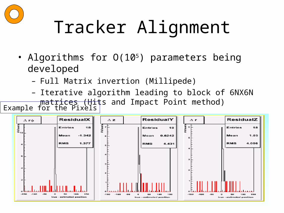
• Algorithms for O(105) parameters being developed– Full Matrix invertion (Millipede)– Iterative algorithm leading to block of 6NX6N matrices (Hits
and Impact Point method)
Example for the Pixels

Misalignments scenarios: 100 pb-1 and a few fb-1

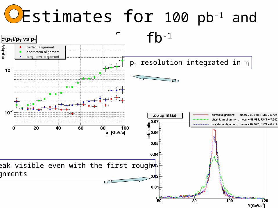
Estimates for 100 pb-1 and a few fb-1
Perfect alignment: resol. ~ 3 % Short-term 100 pb-1: resol. ~ 6 % curve reproduces tracker misalignmentLong term a few fb-1: degraded by factor 1.4 wrt. perfect alignment
Estimates for 100 pb-1 and a few fb-1
pT resolution integrated in
Z peak visible even with the first roughalignments

Primary vertex• Beam spot measured with data, the two beams are
not colliding in the geometrical center of CMS – Plot with minimum bias 500 events only : uncertainty of 8
microns in the transverse plane
x
y
d0
L
d0=L sin (
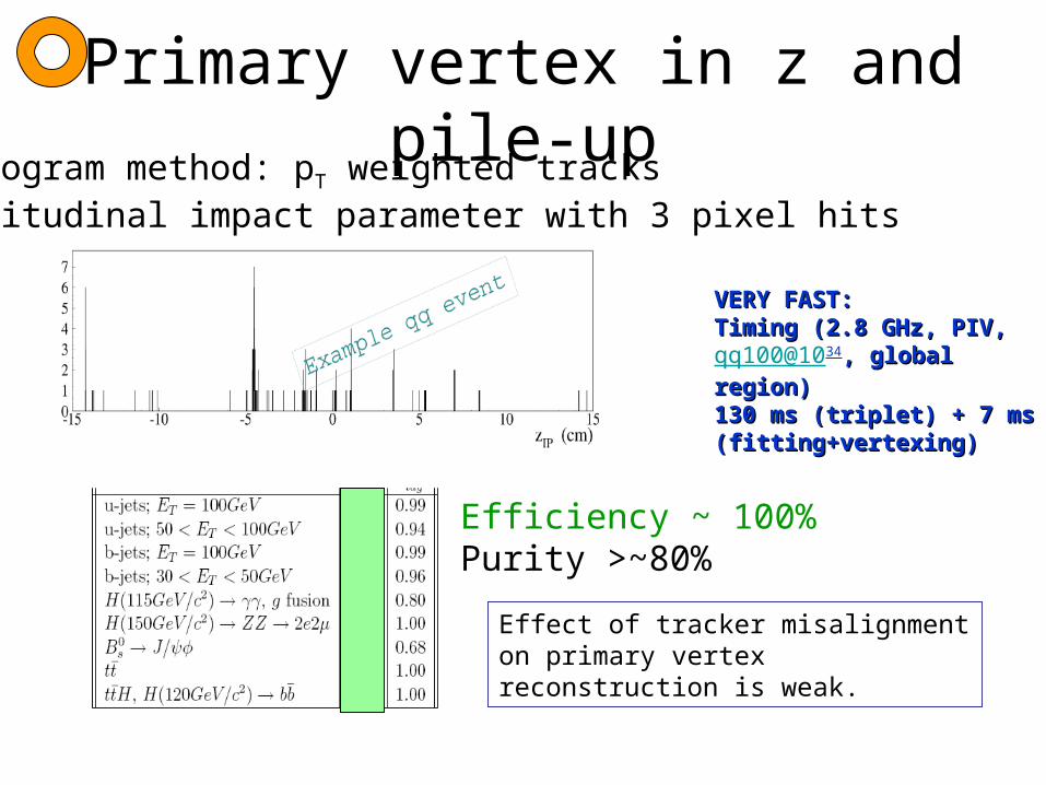
Primary vertex in z and pile-up
VERY FAST:VERY FAST:Timing (2.8 GHz, PIV, Timing (2.8 GHz, PIV, qq100@1034, global region), global region)130 ms (triplet) + 7 ms 130 ms (triplet) + 7 ms (fitting+vertexing)(fitting+vertexing)
Histogram method: pT weighted tracksLongitudinal impact parameter with 3 pixel hits
Efficiency ~ 100%Purity >~80%
Effect of tracker misalignment on primary vertex reconstruction is weak.
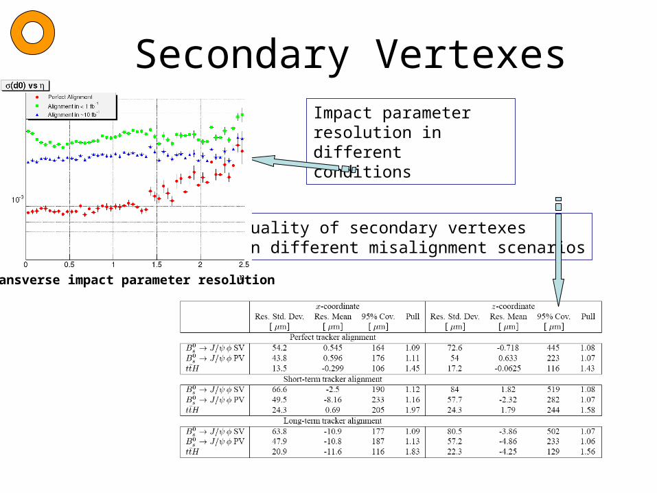
Secondary VertexesImpact parameter resolution in different conditions
Quality of secondary vertexesIn different misalignment scenarios
transverse impact parameter resolution

Electrons and Photons
H
• 76000 PW04 crystals inter-calibrated at the 0.5% level !
• Benchmark channel
• Calibration strategy•All crystals precalibrated with 60Co source (1 MeV gammas)•A few supermodules precalibrated with electron beam (20 e 250 GeV)•The rest using cosmics, with increased APD gain
•Calibration during LHC data taking with electrons •A laser system is monitoring the time-dependent calibration
eW

Electrons and Photons : before Pilot Run
Demonstrated with a supermodule on test beam that the change of transparency of a crystal because of radiation is followed by the laser monitoring system.
Calibration with cosmicsvs test beam
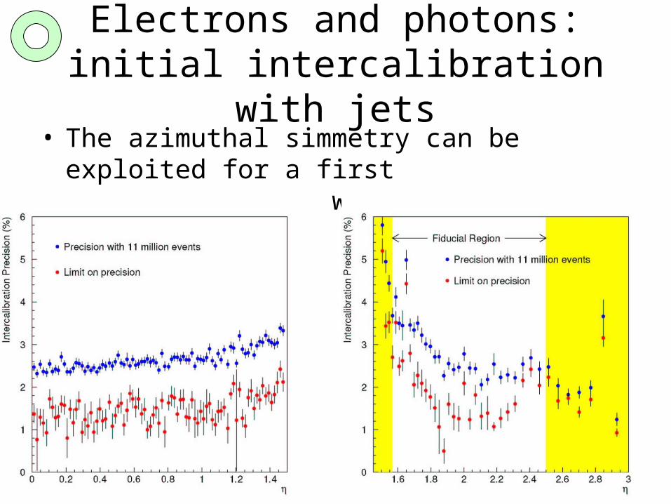
Electrons and photons: initial intercalibration with jets
• The azimuthal simmetry can be exploited for a first intercalibration with inclusive jets
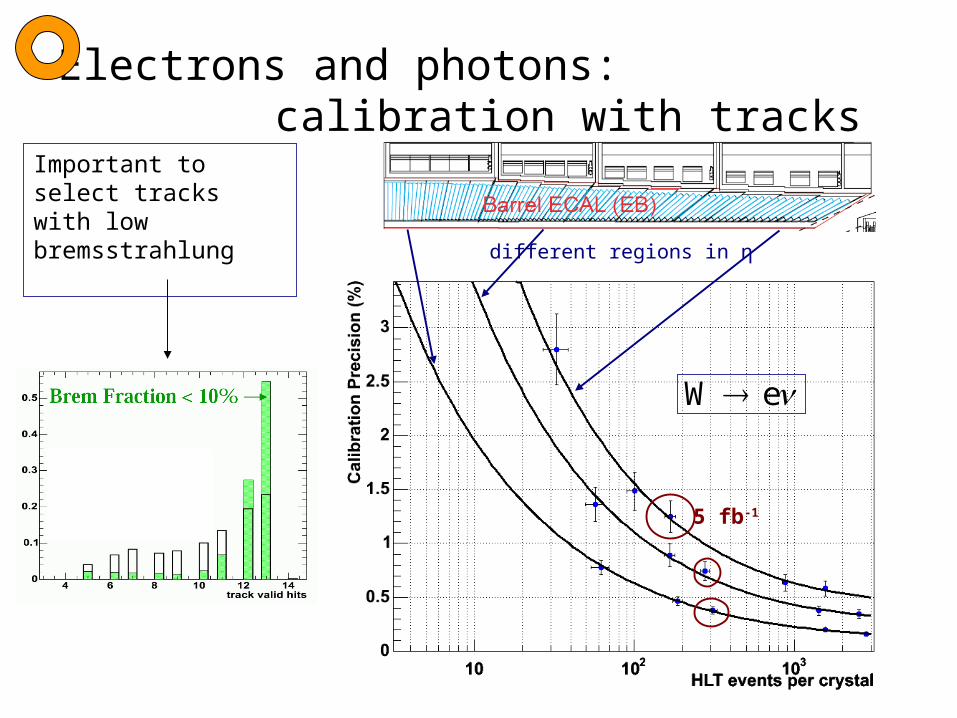
Electrons and photons: calibration with tracks
different regions in η
5 fb-1
eW
Important to select tracks with low bremsstrahlung
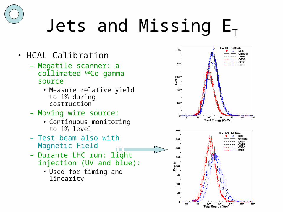
Jets and Missing ET
• HCAL Calibration– Megatile scanner: a
collimated 60Co gamma source
• Measure relative yield to 1% during costruction
– Moving wire source:• Continuous monitoring to
1% level
– Test beam also with Magnetic Field
– Durante LHC run: light injection (UV and blue):
• Used for timing and linearity
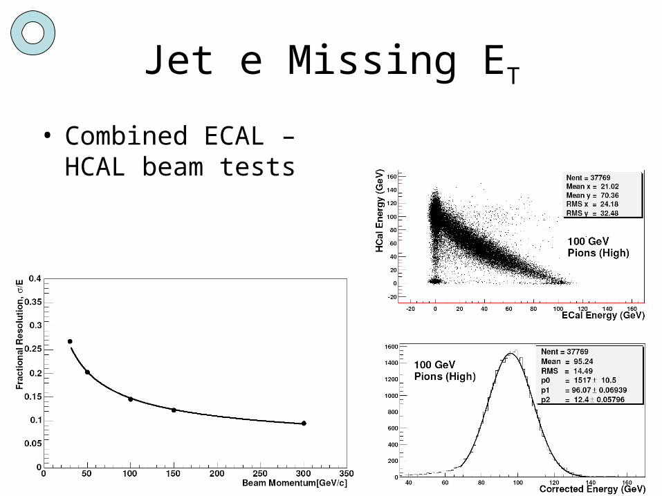
Jet e Missing ET
• Combined ECAL – HCAL beam tests

Monte Carlo calibration of jets Jet Corrections
Given a jet clustering algorithm
Experimentally reconstructed jet
Monte Carlo jet
Partons
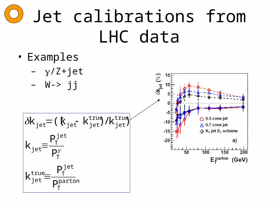
Jet calibrations from LHC data
• Examples– /Z+jet– W-> jj
partonT
jetTtrue
jet
T
jetT
jet
truejet
truejetjetjet
P
Pk
P
Pk
)k/)kk((k
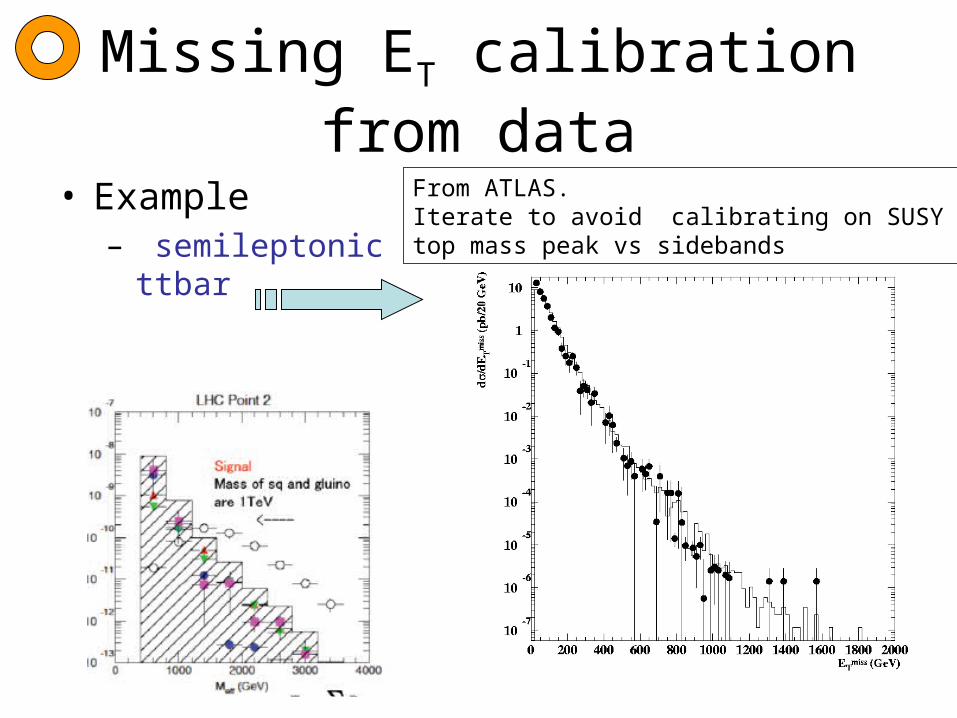
Missing ET calibration from data
• Example– semileptonic ttbar
From ATLAS.Iterate to avoid calibrating on SUSY !!top mass peak vs sidebands

Trigger and DAQ• Level 1 trigger based on muon & calorimeters ,
• then High Level trigger using reconstruction algorithms
Yes/No
L1 trigger
CMS 3.2 s buffer
1 s buffer
High Level Trigger (computer farm)
40 MHz
100 kHz
100 Hz1 MB/event
Off-line analysis

Level-1 Trigger
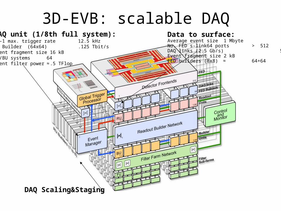
3D-EVB: scalable DAQ DAQ unit (1/8th full system):Lv-1 max. trigger rate 12.5 kHzRU Builder (64x64) .125 Tbit/sEvent fragment size 16 kBRU/BU systems 64Event filter power ≈ .5 TFlop
Data to surface:Average event size 1 MbyteNo. FED s-link64 ports > 512DAQ links (2.5 Gb/s) 512+512Event fragment size 2 kBFED builders (8x8) ≈ 64+64
DAQ Scaling&Staging
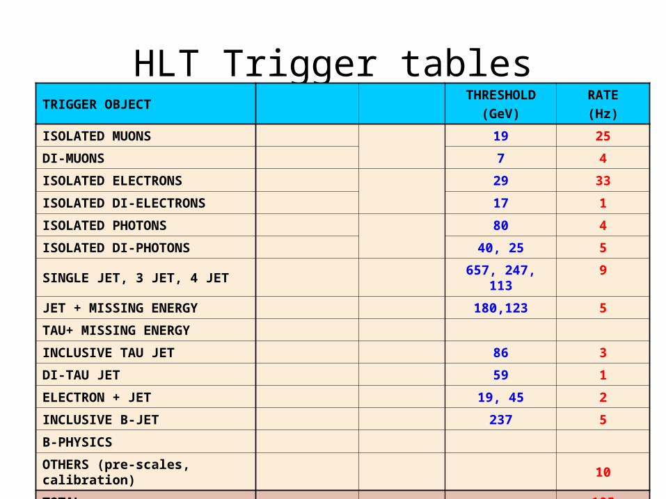
HLT Trigger tablesTRIGGER OBJECT
THRESHOLD(GeV)
RATE(Hz)
ISOLATED MUONS 19 25
DI-MUONS 7 4
ISOLATED ELECTRONS 29 33
ISOLATED DI-ELECTRONS 17 1
ISOLATED PHOTONS 80 4
ISOLATED DI-PHOTONS 40, 25 5
SINGLE JET, 3 JET, 4 JET657, 247,
1139
JET + MISSING ENERGY 180,123 5
TAU+ MISSING ENERGY
INCLUSIVE TAU JET 86 3
DI-TAU JET 59 1
ELECTRON + JET 19, 45 2
INCLUSIVE B-JET 237 5
B-PHYSICS
OTHERS (pre-scales, calibration)
10
TOTAL 105
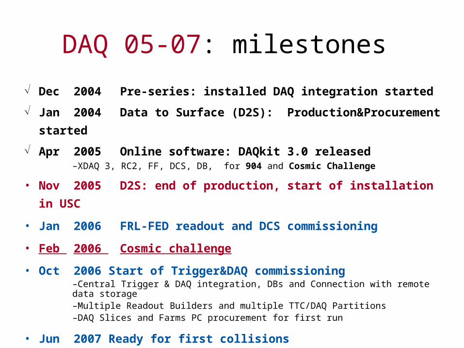
DAQ 05-07: milestones
Dec 2004 Pre-series: installed DAQ integration started
Jan 2004 Data to Surface (D2S): Production&Procurement started
Apr 2005 Online software: DAQkit 3.0 released–XDAQ 3, RC2, FF, DCS, DB, for 904 and Cosmic Challenge
• Nov 2005 D2S: end of production, start of installation in USC
• Jan 2006 FRL-FED readout and DCS commissioning
• Feb 2006 Cosmic challenge
• Oct 2006 Start of Trigger&DAQ commissioning–Central Trigger & DAQ integration, DBs and Connection with remote data storage–Multiple Readout Builders and multiple TTC/DAQ Partitions–DAQ Slices and Farms PC procurement for first run
• Jun 2007 Ready for first collisions
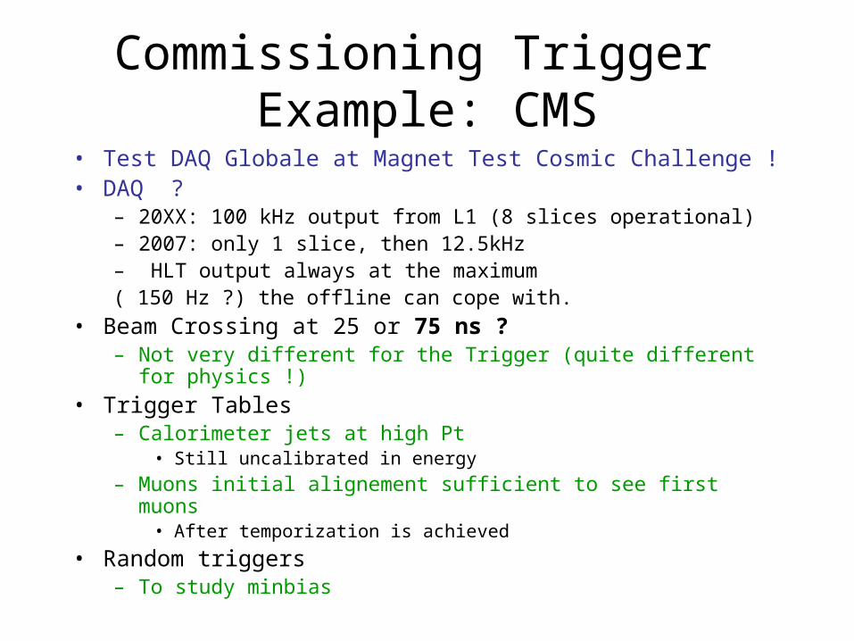
Commissioning Trigger Example: CMS
• Test DAQ Globale at Magnet Test Cosmic Challenge !• DAQ ?
– 20XX: 100 kHz output from L1 (8 slices operational)– 2007: only 1 slice, then 12.5kHz– HLT output always at the maximum( 150 Hz ?) the offline can cope with.
• Beam Crossing at 25 or 75 ns ?– Not very different for the Trigger (quite different for physics !)
• Trigger Tables– Calorimeter jets at high Pt
• Still uncalibrated in energy
– Muons initial alignement sufficient to see first muons• After temporization is achieved
• Random triggers – To study minbias

Trigger issues for CMS Pilot Run
• L1:– Muon Ok – Calo barrel Ok (ECAL
endcaps in 2008)
• HLT– Initially algorithms
without pixels(installed after Pilot Run)
• Pixels used to– Identify primary vertex
• Irrelevant at low luminosity no pileup
• No pile-up: less tracking combinatorial
– Refine muon pt• strip tracker and a bit
reconstruction time should be enough
– Isolation• Could use strip stracker
– Particle Id: separate e+ from e- and gamma from jet