Lezione 2 - Università degli Studi di...
42
INFORMATICA INDUSTRIALE Prof. Christian Forlani [email protected] Tutor: Stefano Brusamolino [email protected] Lezione 2
Transcript of Lezione 2 - Università degli Studi di...
INFORMATICA
INDUSTRIALE
Prof. Christian [email protected]
Tutor: Stefano [email protected]
Lezione 2

Lezione 2 2
Informatica Industriale
» Oscillator» Reset» Architecture» CPU (Central Processing Unit) and System Bus» ALU (Arithmetic Logical Unit)» Hardware 8x8 Multiplier» Memory Map» Table Read / Table Write» System Bus» Interrupts» Instruction Set
Device Structure: Core

Lezione 2 3
Informatica Industriale
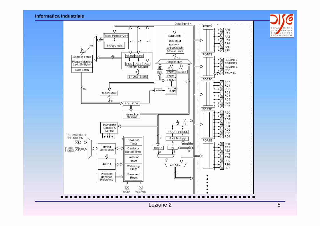
ArchitecturePIC
Lezione 2 4
Informatica Industriale
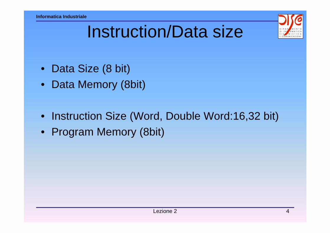
Instruction/Data size
• Data Size (8 bit)
• Data Memory (8bit)
• Instruction Size (Word, Double Word:16,32 bit)• Program Memory (8bit)
Lezione 2 5
Informatica Industriale
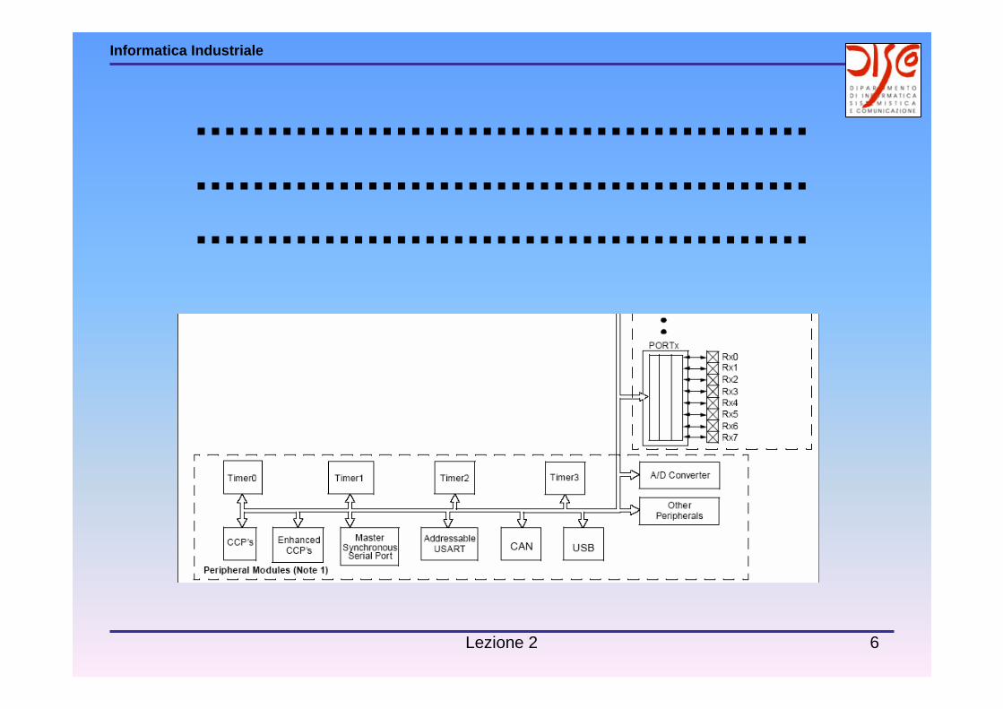
Lezione 2 6
Informatica Industriale

Lezione 2 7
Informatica Industriale
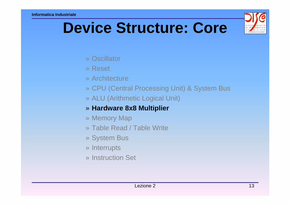
» Oscillator» Reset » Architecture» CPU (Central Processing Unit) and System Bus» ALU (Arithmetic Logical Unit)» Hardware 8x8 Multiplier» Memory Map» Table Read / Table Write» System Bus» Interrupts» Instruction Set
Device Structure: Core

Lezione 2 8
Informatica Industriale
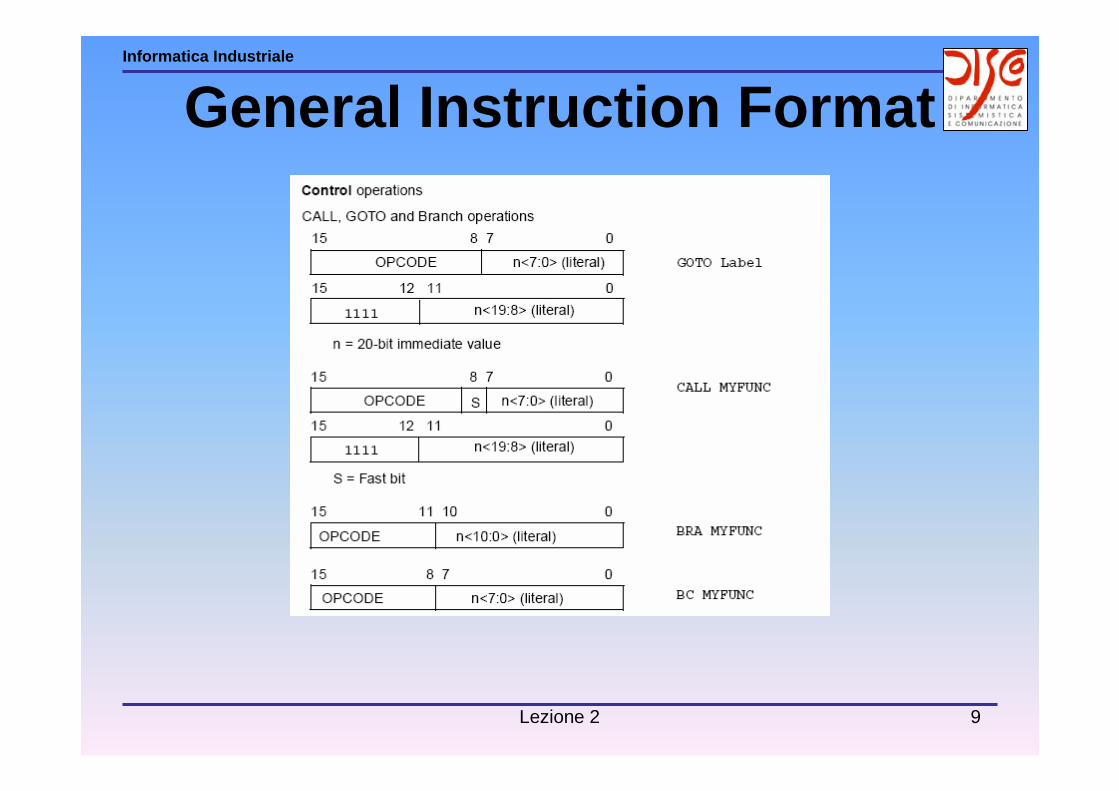
General Instruction Format
Lezione 2 9
Informatica Industriale
General Instruction Format

Lezione 2 10
Informatica Industriale
» Oscillator» Reset » Architecture» CPU (Central Processing Unit) & System Bus» ALU (Arithmetic Logical Unit)» Hardware 8x8 Multiplier» Memory Map» Table Read / Table Write» System Bus» Interrupts» Instruction Set
Device Structure: Core

Lezione 2 11
Informatica Industriale
ALU (Arithmetic Logical Unit)

Lezione 2 12
Informatica Industriale
Status Register
• N =Negative bit• OV=Overflow bit• Z =Zero bit• DC=Digit Carry (Half Carry)• C =Carry
Lezione 2 13
Informatica Industriale
» Oscillator» Reset » Architecture» CPU (Central Processing Unit) & System Bus» ALU (Arithmetic Logical Unit)» Hardware 8x8 Multiplier» Memory Map» Table Read / Table Write» System Bus» Interrupts» Instruction Set
Device Structure: Core
Lezione 2 14
Informatica Industriale
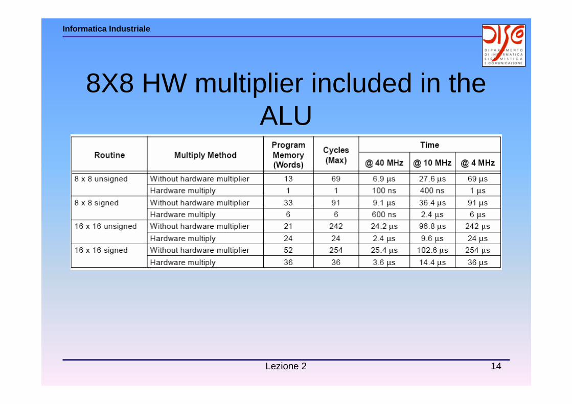
8X8 HW multiplier included in the ALU

Lezione 2 15
Informatica Industriale
» Oscillator» Reset » Architecture» CPU (Central Processing Unit) & System Bus» ALU (Arithmetic Logical Unit)» Hardware 8x8 Multiplier» Memory Map» Table Read / Table Write» System Bus» Interrupts» Instruction Set
Device Structure: Core
Lezione 2 16
Informatica Industriale
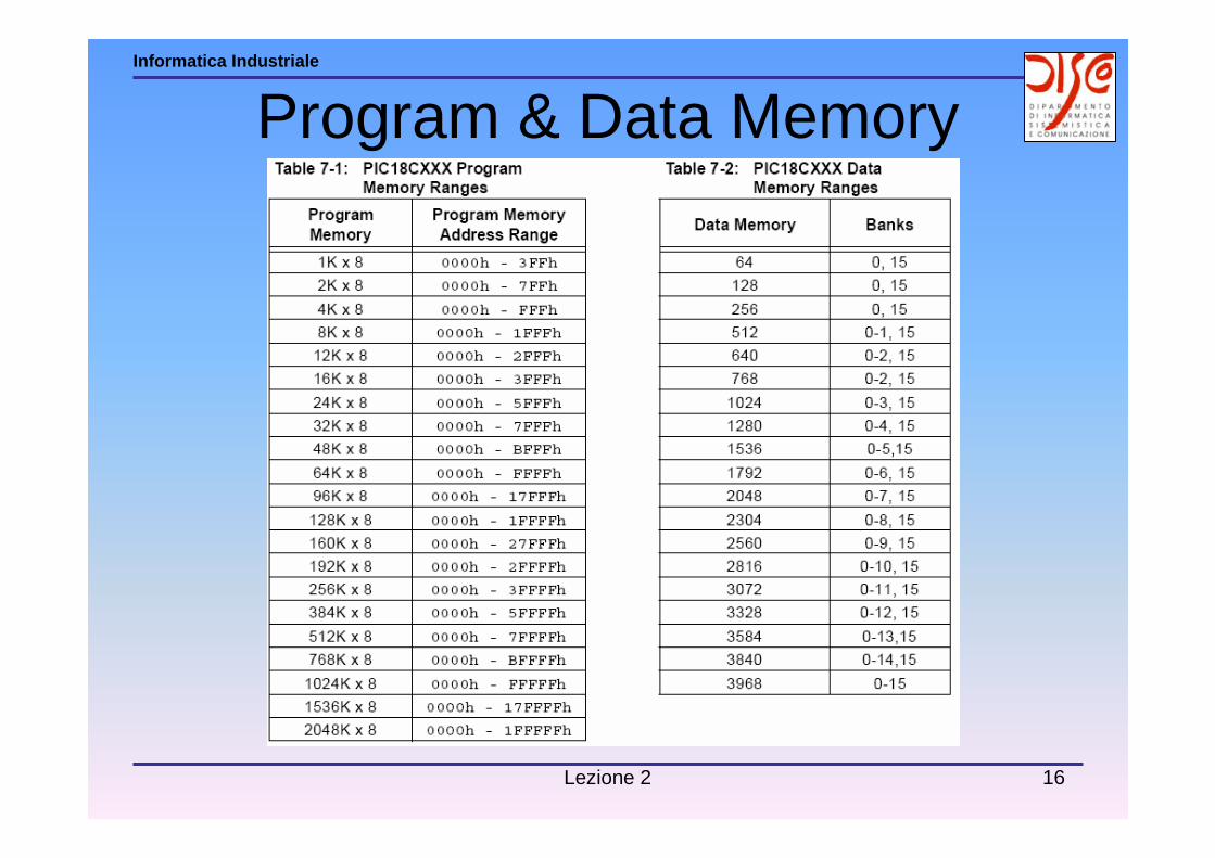
Program & Data Memory
Lezione 2 17
Informatica Industriale
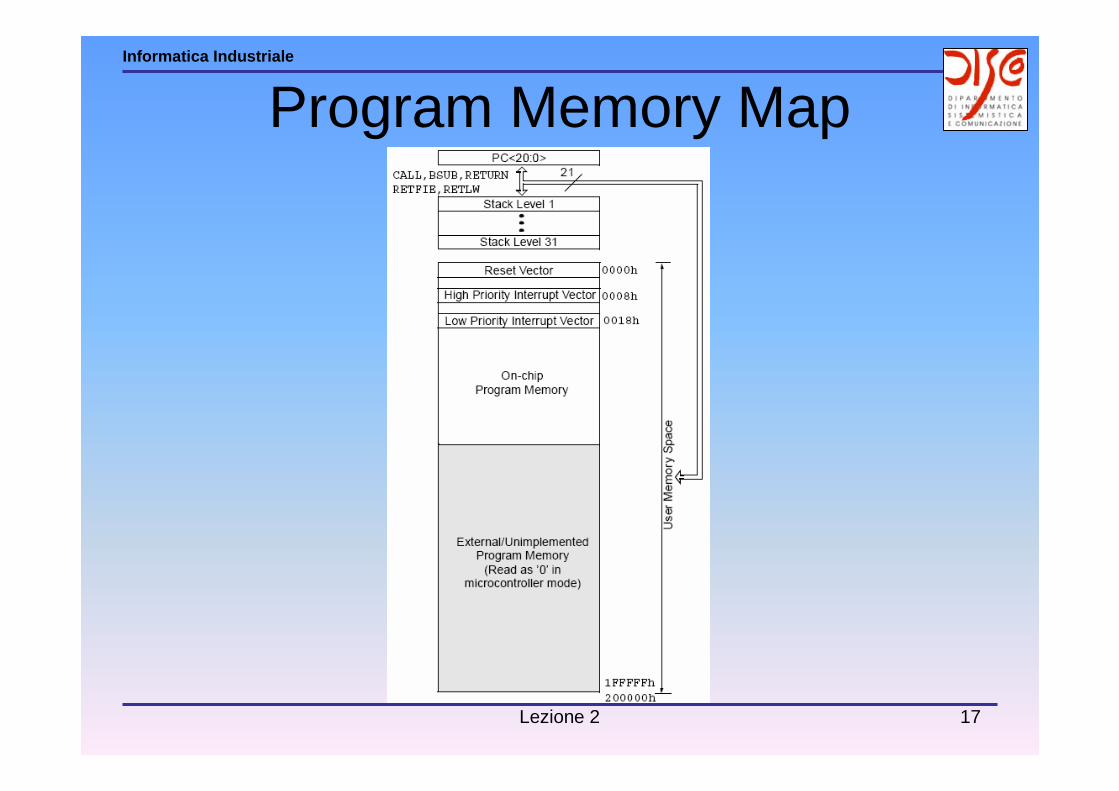
Program Memory Map
Lezione 2 18
Informatica Industriale
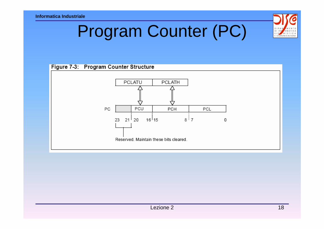
Program Counter (PC)

Lezione 2 19
Informatica Industriale
Data Memory Map
Lezione 2 20
Informatica Industriale
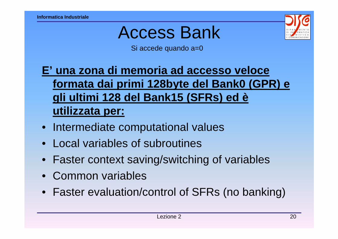
Access Bank
E’ una zona di memoria ad accesso veloce formata dai primi 128byte del Bank0 (GPR) e gli ultimi 128 del Bank15 (SFRs) ed èutilizzata per:
• Intermediate computational values• Local variables of subroutines• Faster context saving/switching of variables
• Common variables• Faster evaluation/control of SFRs (no banking)
Si accede quando a=0

Lezione 2 21
Informatica Industriale
» Oscillator» Reset » Architecture» CPU (Central Processing Unit) & System Bus» ALU (Arithmetic Logical Unit)» Hardware 8x8 Multiplier» Memory Map» Table Read / Table Write» System Bus» Interrupts» Instruction Set
Device Structure: Core

Lezione 2 22
Informatica Industriale
Table Write• E’ una tabella che permette il trasferimento di dati dalla
Data Memory alla Program Memory.
NB: Per i dispositivi con memoria EPROM, i bit della Program Memory possono essere portati da 1 a 0 ma non viceversa!!

Lezione 2 23
Informatica Industriale
Table Read• E’ una tabella che permette il trasferimento di dati dalla
Program Memory alla Data Memory.
Lezione 2 24
Informatica Industriale
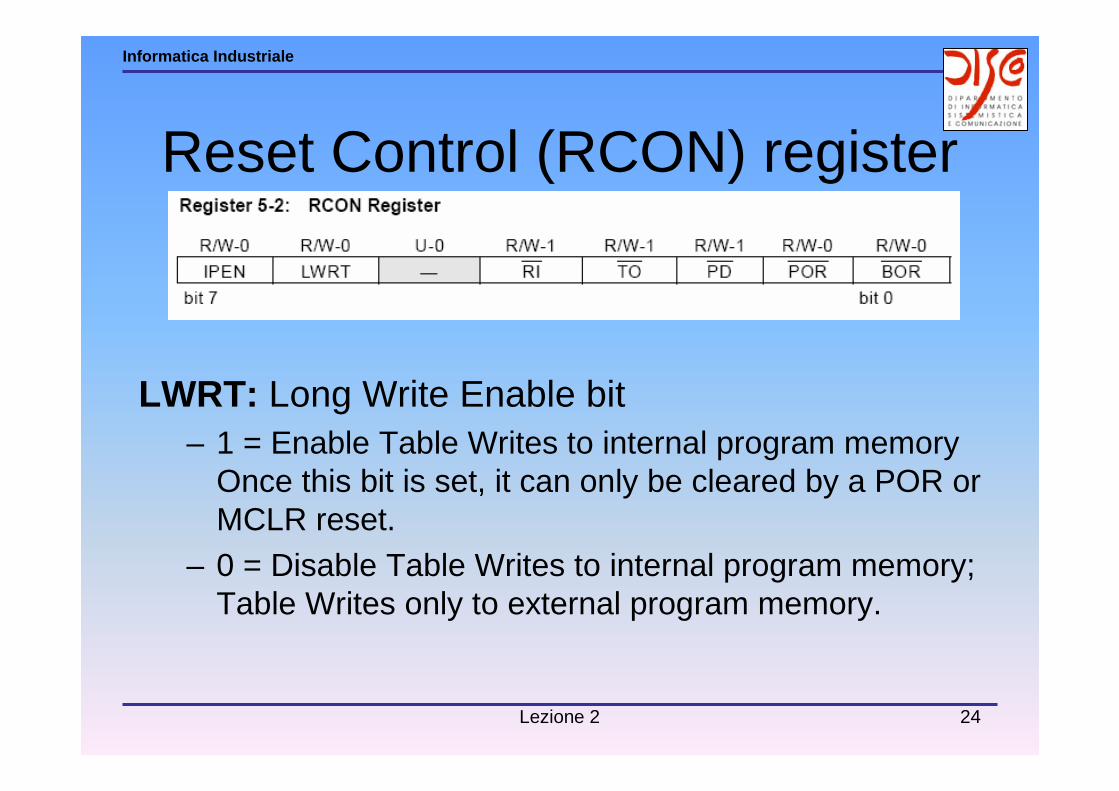
Reset Control (RCON) register
LWRT: Long Write Enable bit– 1 = Enable Table Writes to internal program memory
Once this bit is set, it can only be cleared by a POR or MCLR reset.
– 0 = Disable Table Writes to internal program memory; Table Writes only to external program memory.
Lezione 2 25
Informatica Industriale
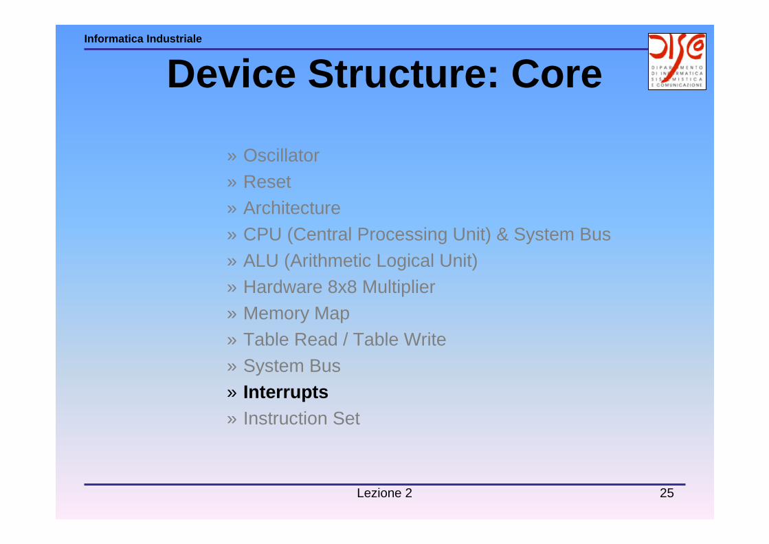
» Oscillator» Reset » Architecture» CPU (Central Processing Unit) & System Bus» ALU (Arithmetic Logical Unit)» Hardware 8x8 Multiplier» Memory Map» Table Read / Table Write» System Bus» Interrupts» Instruction Set
Device Structure: Core

Lezione 2 26
Informatica Industriale
InterruptsInterrupts can come from many sources. These sources cur rently include:
– External interrupt from the INT, INT1, and INT2 pins– Change on RB7:RB4 pins– TMR0,1,2,3Overflow– USART Interrupts
• Receive buffer full• Transmit buffer empty
– SSPInterrupt– SSP I2C bus collision interrupt– A/D conversion complete– CCP interrupt– LVD Interrupt– Parallel Slave Port– CAN interrupts
• Receive 1,2 buffer • Receive invalid• Transmit 1,2,3 buffer• Bus wakeup• Bus invalid error

Lezione 2 27
Informatica Industriale
InterruptsAs other peripheral modules are developed, they will have interrupt sources.
These sources will map into the 10 registers used in the c ontrol and status of interrupts. These registers are:
– INTCON– INTCON1– INTCON2– INTCON3– PIR1– PIR2– PIE1– PIE2– IPR1– IPR2
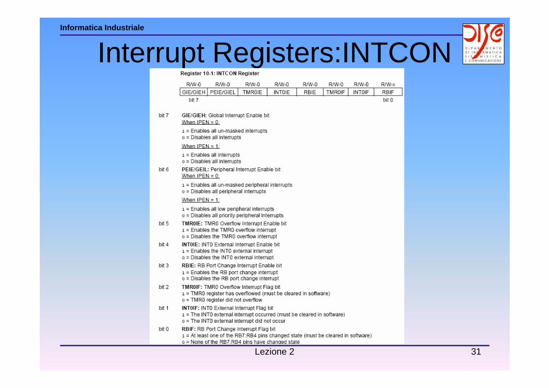
The INTCON register contains the GIE/GIEH bit. This is the Global Interrupt Enablebit. When this bit is set, all interrupts are enabled. If needed for any single device, additional INTCON, PIR,PIE, and IPR registers will be defined.
Lezione 2 28
Informatica Industriale

Lezione 2 29
Informatica Industriale
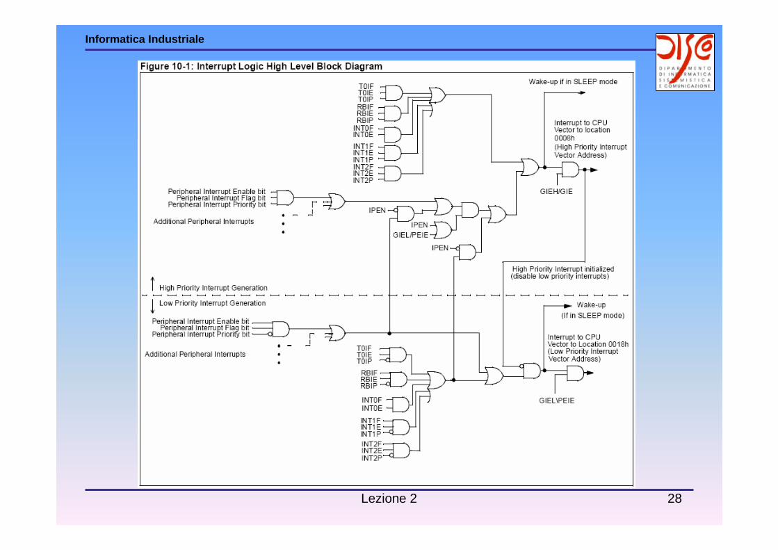
High Priority Interrupt Logic Block

Lezione 2 30
Informatica Industriale
Low Priority Interrupt Logic Block
Lezione 2 31
Informatica Industriale
Interrupt Registers:INTCON

Lezione 2 32
Informatica Industriale
Interrupt Registers:INTCON2

Lezione 2 33
Informatica Industriale
Interrupt Registers:INTCON3

Lezione 2 34
Informatica Industriale
Peripheral Interrupt Enable:PIE

Lezione 2 35
Informatica Industriale
Peripheral Interrupt Registers:PIR

Lezione 2 36
Informatica Industriale
Interrupt Priority Registers:IPR

Lezione 2 37
Informatica Industriale
Peripheral Interrupt Registers:PIR
Lezione 2 38
Informatica Industriale
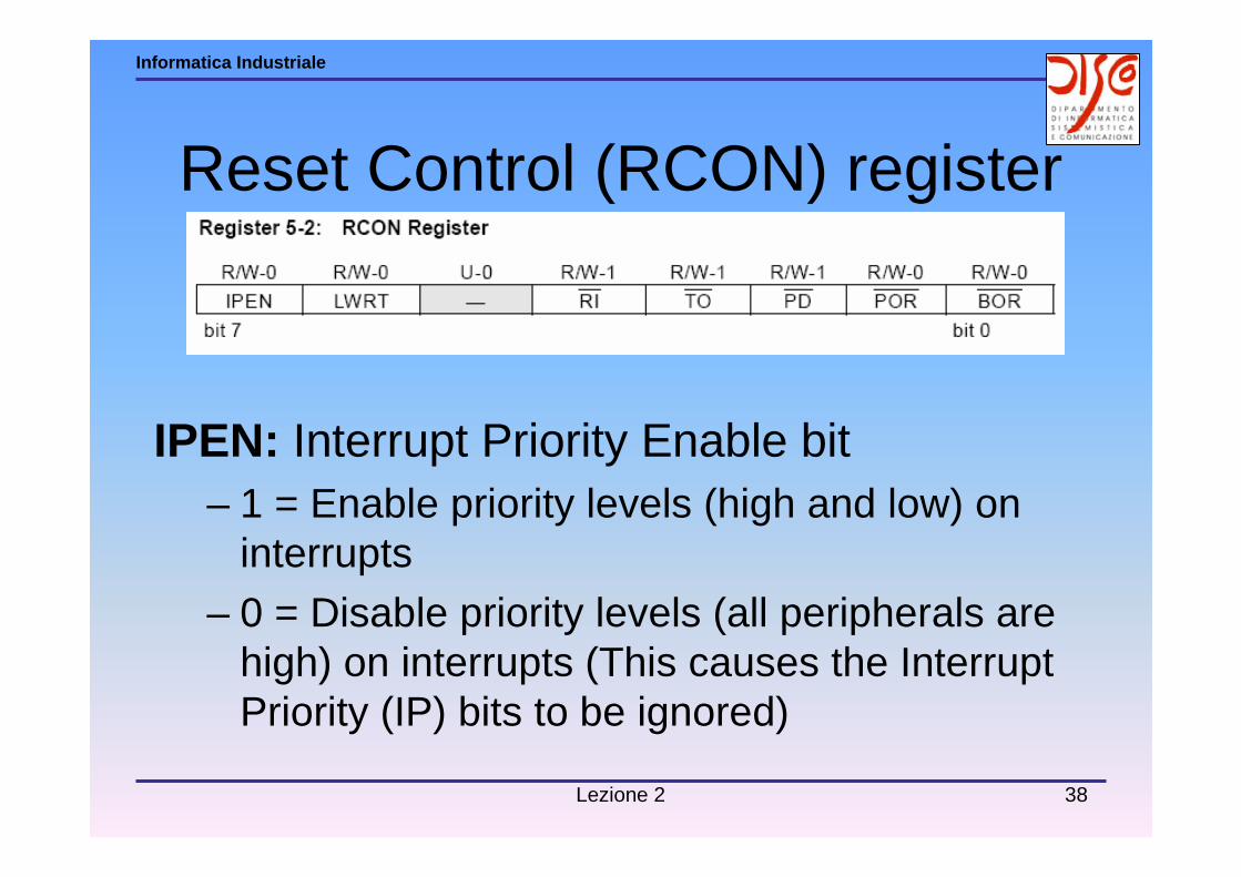
Reset Control (RCON) register
IPEN: Interrupt Priority Enable bit– 1 = Enable priority levels (high and low) on
interrupts
– 0 = Disable priority levels (all peripherals are high) on interrupts (This causes the Interrupt Priority (IP) bits to be ignored)
Lezione 2 39
Informatica Industriale
» Oscillator» Reset » Architecture» CPU (Central Processing Unit) & System Bus» ALU (Arithmetic Logical Unit)» Hardware 8x8 Multiplier» Memory Map» Table Read / Table Write» System Bus» Interrupts» Instruction Set
Device Structure: Core

Lezione 2 40
Informatica Industriale

Lezione 2 41
Informatica Industriale
Lezione 2 42
Informatica Industriale