Lewis Structures, Molecular Geometry, Polarity, Intermolecular Forces

Copyright Catalyst Education 2020
Lewis Structures and Molecular Modeling
Objectives • Practice drawing and interpreting Lewis structures• Allow visualization of three-dimensional models of molecules to help associate
Lewis structures with molecular shapes
Introduction
Chemical Structures There are a number of different ways to represent molecules, as illustrated for NH3 in Figure 1.
• A Lewis structure (Figure 1a) is meant to represent chemical bonding and the distribution of electrons – as bonds and lone pairs – in the structure.
• A ball-and-stick model (Figure 1b) is a simplified 3-dimensional picture that shows the relative arrangement of atoms in a molecule, with the balls representing the centers of atoms and the sticks the location of bonds. Ball-and-stick models are good for showing molecular shape.
• A space-filling model (Figure 2c) is an extension of the ball-band-stick model which shows the “full size”1 atoms and how they overlap. These are particularly useful for visualizing what happens when molecules approach each other.
Lewis Structures Lewis electron dot structures have long been used to represent bonding in simple molecules. The procedure for drawing Lewis structures is provided in your chemistry text. The octet rule often provides the key guidelines for drawing structures. With a little practice, a wide variety of chemical structures may be drawn quickly and easily.
Despite their simplicity, Lewis structures often provide tremendous insight into important molecular properties. Furthermore, Lewis structures are also supported by theoretical models for bonding, particularly Valence Bond Theory, and they allow one to estimate molecular shapes using Valence Shell Electron Pair Repulsion (VSEPR) Theory.
1 “Full-size” is not entirely accurate because in the quantum mechanical description of atoms, atoms do not have precise boundaries. The atoms sizes in space-filling models normally represent sizes corresponding to how close molecules can get to each other without a chemical bond.
Figure 1 Representations of Ammonia (a) Lewis structure;(b) ball-and-stick model; (c) space-filling model

Copyright Catalyst Education 2020
Lewis Structures and Molecular Modeling
2
VSEPR Theory One of the limitations to Lewis structures is that they represent 3-dimensional molecular structures as 2-dimensional images on a flat page. VSEPR theory provides a means of predicting a molecule’s shape based on the disposition of bonding electrons and lone pair electrons around each atom. VSEPR theory is also covered in your chemistry text.
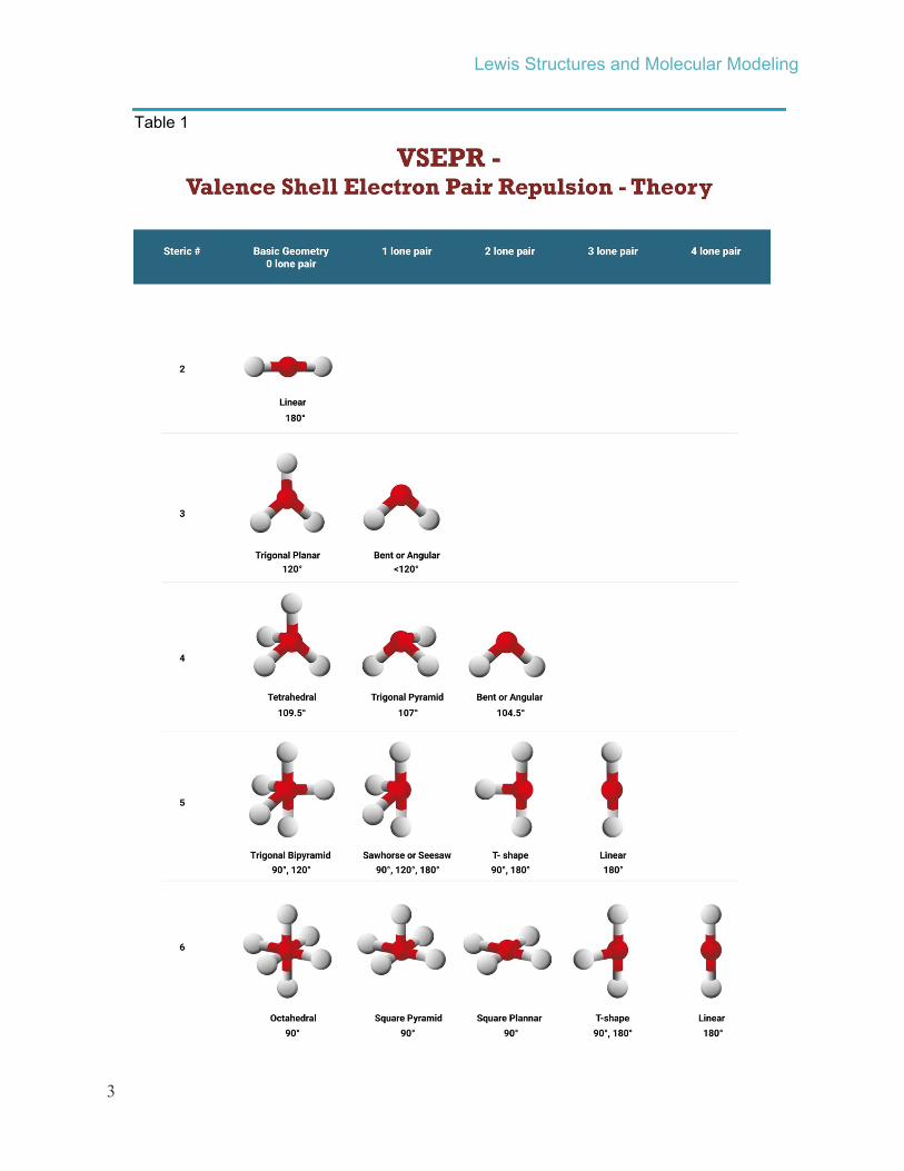
VSEPR Theory focuses first on the arrangements of electron groups. where an electron group is all of the electrons in any bond (electrons in a single, double, or triple bond are considered one “group”) or in a lone pair (lone pair = one group). The basic tenet of VSEPR Theory is that electron groups spread out as much as possible to minimize electron-electron repulsions. Idealized VSEPR Theory electron geometries (spatial arrangements of electron groups) for two to six groups of electrons are shown in Figure 2.
Table 1 shows the geometries of molecular geometry (shape), which refers to the arrangement of atoms around a central atom. Lone pairs on the central atom are considered part of the central atom, not separate atoms. Idealized molecular shapes corresponding to linear, trigonal planar, and tetrahedral electron geometries are illustrated in Table 1. Actual bond angles often differ from the idealized angles indicated in Table 1. In VSEPR theory, the deviations from ideal angles are generally attributed to differences in the sizes of atoms, and to the ability of lone pairs to spread out more than bonding electrons. For example, the idealized H–O–H bond angle for water is 109.5° (the tetrahedral bond angle), but the actual bond angle is 104.5°.
Figure 2 Idealized electron geometries in VSEPR Theory for 2 – 6 groups of electrons. The open circles can represent either bonded atoms or lone pairs of electrons. The angles shown are idealized.
Electron geometry – The spatial arrangement of electrons in a molecule, usually described with respect to a central atom. Electron geometry describes the arrangement of all electrons, both bonding electrons and non-bonding (lone pair) electrons.
Molecular geometry – The spatial arrangement of atoms in a molecule, usually described with respect to a central atom; same as molecular shape. Molecular geometry focusing on where atoms are placed, and recognizes lone pairs of electrons as being a part of the atom to which they are assigned.
Idealized bond angles – The angles formed between bonded atoms for the perfect molecular geometry predicted from VSEPR Theory.
Copyright Catalyst Education 2020
Lewis Structures and Molecular Modeling
3
Table 1

Copyright Catalyst Education 2020
Lewis Structures and Molecular Modeling
4
Molecular Modeling Molecular modeling programs are computer programs that attempt to represent the structures and molecular interactions of molecules and to provide corresponding graphical images. There are a wide range of molecular modeling programs, but their general aim is to predict the lowest energy (most stable) arrangement of atoms. Programs range from simple “parameterize” programs that make predictions based on force fields (mathematical descriptions of attractions and repulsions among atoms, based on sets of mathematical parameters), to high-level programs based on quantum mechanical calculations. Generally, as the level of the program increases, the output becomes more accurate, but generally at a high cost of computational time. Luckily, modern parameterized programs are often of very good quality and provide good results as long as their limitations are recognized. You will use a fairly simple program called Avogadro for this laboratory.
Avogadro uses force field calculations to estimate the interactions between atoms in different environments. One set of force fields, MMFF94 (Merck Molecular Force Field 94) is designed to give best results for organic structures, and generally works well (and rapidly) for molecules that contain carbon, nitrogen, oxygen, and some other elements. Another force field, UFF (Universal Force Field) works for all types of atoms, but is not as accurate for organic compounds, and also operates more slowly. When used appropriately, the force field calculations will provide fairly good representations of molecular geometries, including deviations from idealized angles from VSEPR theory.
Overview of the Lab
Part I The first part of the lab will be an introduction to the Avogadro program. You will start with by drawing CH4, and carry out a series of transformations ending in CCl2CH2, as shown below:
You will first enter the CH4 structure in Avogadro and get some practice with Avogadro’s controls and manipulations. You will go through additional steps to ending up with Cl2CCH2, evaluating structures along the way – you will use Avogadro to measure bond angles (which are generally pretty close to experimental bond angles) and compare them to the theoretical bond angles predicted by VSEPR theory.
Part II You will use Avogadro to explore intermolecular attractions, entering two (or more) molecules on the same screen and looking to see how they interact with each other.
Copyright Catalyst Education 2020
Lewis Structures and Molecular Modeling
5
Part III For this section, you will receive a handout in the lab. It will provide instructions on how to “build” a number of structures using Avogadro. As part of this section, you will also sketch out the Lewis structure based on the structure shown in Avogadro. The Lewis structure will need to be complete, showing all valence electrons, including those in lone pairs. Also, in this section you will evaluate a more complex structure provided within Avogadro, again drawing the complete Lewis structure. Throughout Part III, you will measure specific bond angles, and compare those to angles predicted by Avogadro.
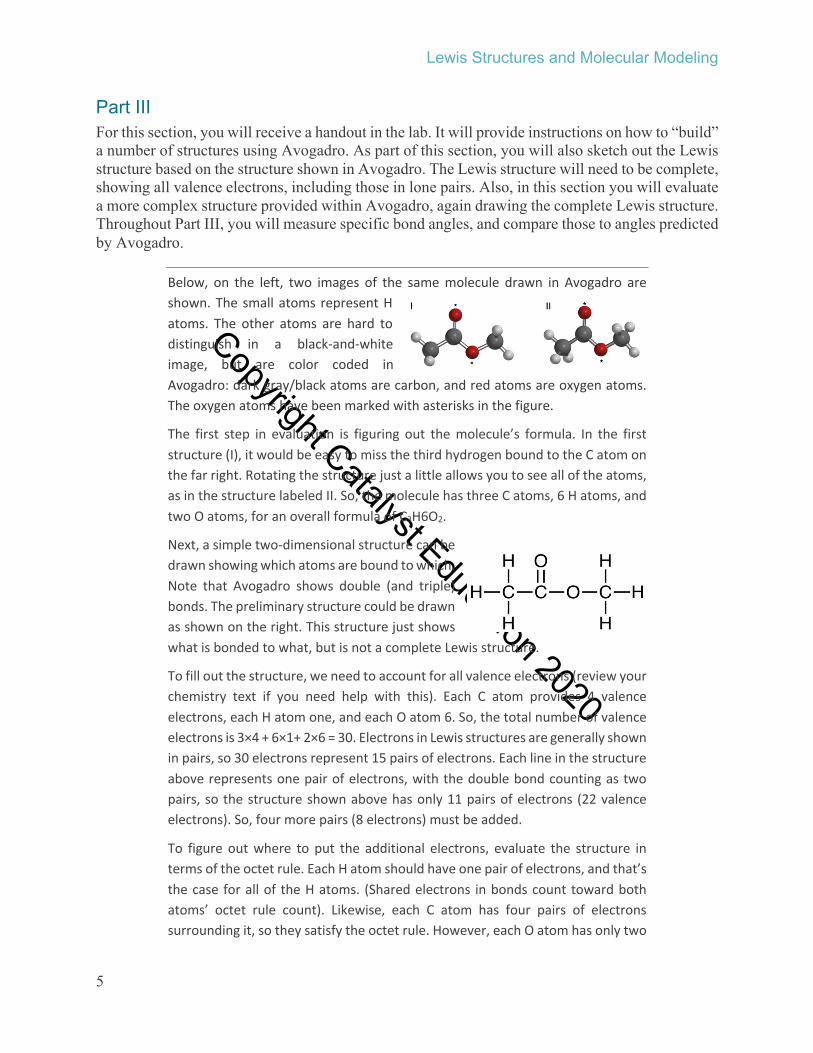
Below, on the left, two images of the same molecule drawn in Avogadro are shown. The small atoms represent Hatoms. The other atoms are hard to distinguish in a black-and-whiteimage, but are color coded inAvogadro: dark gray/black atoms are carbon, and red atoms are oxygen atoms.The oxygen atoms have been marked with asterisks in the figure.
The first step in evaluation is figuring out the molecule’s formula. In the firststructure (I), it would be easy to miss the third hydrogen bound to the C atom on the far right. Rotating the structure just a little allows you to see all of the atoms, as in the structure labeled II. So, the molecule has three C atoms, 6 H atoms, and two O atoms, for an overall formula of C3H6O2.
Next, a simple two-dimensional structure can bedrawn showing which atoms are bound to which.Note that Avogadro shows double (and triple) bonds. The preliminary structure could be drawn as shown on the right. This structure just shows what is bonded to what, but is not a complete Lewis structure.
To fill out the structure, we need to account for all valence electrons (review your chemistry text if you need help with this). Each C atom provides 4 valenceelectrons, each H atom one, and each O atom 6. So, the total number of valenceelectrons is 3×4 + 6×1+ 2×6 = 30. Electrons in Lewis structures are generally shownin pairs, so 30 electrons represent 15 pairs of electrons. Each line in the structureabove represents one pair of electrons, with the double bond counting as two pairs, so the structure shown above has only 11 pairs of electrons (22 valenceelectrons). So, four more pairs (8 electrons) must be added.
To figure out where to put the additional electrons, evaluate the structure in terms of the octet rule. Each H atom should have one pair of electrons, and that’s the case for all of the H atoms. (Shared electrons in bonds count toward both atoms’ octet rule count). Likewise, each C atom has four pairs of electrons surrounding it, so they satisfy the octet rule. However, each O atom has only two

Copyright Catalyst Education 2020
Lewis Structures and Molecular Modeling
6
pairs of electrons (4 valence electrons). Adding two lone pairs to each O atom will allow it to satisfy the octet rule, and will also get the overall valence electron count up to 30 as required. So, the structure shown on the right represents the final Lewis structure.
Using Avogadro, it is possible to measure the bond angles for the structure. Three bond angles are shown in the figure on the right. How do these compare to idealized values from VSEPR theory?
For the angle labeled “a”, the central atom is carbon with four groups of electrons (four single bonds)around it. The idealized electron geometry is tetrahedral, with bonds 109.5° apart. The observed bond angle (from Avogadro) is 108.6°, which is veryclose.
For the angle labeled “b”, the central atom is carbon with three groups of electrons (two single bonds and one double bond) around it. The idealized geometry is trigonal planar, with an idealized bondangle of 120°. The observed angle is 124.5°, a bit larger than expected, but reasonably consistent with
the trigonal planar assignment. Also, if the structureis rotated a bit as shown on the right, it is clear that the atoms around the centralC (in the box) are all in the same plane.
Finally, for the angle labeled “c”, the central atom is oxygen with four electron groups (two single bonds and two lone pairs) around it. The idealized electrongeometry would be tetrahedral, but the molecular geometry (shape) would be bent. The idealized bond angle would be 109.5°. The observed angle of 113.9° is a bit larger, but generally in agreement.

Copyright Catalyst Education 2020
Lewis Structures and Molecular Modeling
7
Quick Summary of Tools
Add, change, delete atoms or bonds
Use tool. Left-click adds new atom or changes old atom;left-click and drag on atom adds bonded atom;left-click on bond “toggles” from single to double to triple;right-click deletes atom or bond
Move display around
Use right-click and drag with any tool except or
Reorient molecules Use left-click and drag with any tool except or
Rescale display Center scroll with any tool.
Minimize energy Use tool.
Measure angles Use tool.
Limitations to Avogadro
Neutral species only – Don’t try to draw structures of ions in Avogadro – the program assumes that all structures are neutral.
Impossible/non-octet rule structures – If you draw an unreasonable structure, Avogadro won’t try to stop you.
Limitations for more than four groups of electrons around the central atom – Avogadro’s force-field parameters are often unreliable for molecules that (legitimately) exceed the octet rule. Stick with octet-rule structures, at least for this lab.
Stability issues – An occasional “glitch” that shuts down the program can be expected. It is usually pretty easy to reconstruct a molecule, so this usually is not a major issue.

Copyright Catalyst Education 2020
Lewis Structures and Molecular Modeling
8
Avogadro’s Toolbar
This is the tool for adding or deleting atoms. When this tool is selected, a drawing control box will be displayed. This will allow you to select what atom will be added when you left click. Some important notes:
To add an atom:
• If you left-click in an open area, the selected atom will be added.• If you left-click on an existing atom and then drag (holding down the button), the new
atom will be displayed bonded to the first atom.• If the “Adjust Hydrogens” box is checked (default setting), hydrogen atoms are
automatically added to (or removed from) the structure to attain the “normal”number of bonds for each atom.
To change an atom:
• If you left-click and release on an existing atom, the atom will be changed into the new atom.
• If you right-click and release on an atom, the atom will be deleted. If “AdjustHydrogens” is selected, the H atoms cannot be deleted.
To change a bond from single to double (etc.):
• Each time you left-click on a bond, the bond will switch from single bond to double bond to triple bond, then back to single bond.
• If you right-click on an existing bond, the bond will be deleted and the structure willsplit into two parts.
Adjusting size of displayed atoms:
• The center scroll adjusts the size of the displayed atoms. This also works for most ofthe tools.
If you make a mistake (e.g., accidentally add an atom where you don’t want it to be), use Ctrl-Z to undo the last step (or series of steps).
This control can be used to rotate the structure. All of its functions can also be achieved withother controls, and so they won’t be covered here.This control can be used to align the structure along specific axes, but will not be used here.
This is the “grab and drag” control, and it will be used a lot here. When this control is selected:
• If you left-click and drag on an atom, you can pull the atom to a new location (otheratoms may move with it, depending on other settings).
• If you left-click and drag on open space around an atom, you can rotate the entirestructure.
• If you right-click and drag on open space around the structure, you can move thedisplay around. (If you right-click on an atom, it has no effect.)
• The center scroll allows you to adjust display size.

Copyright Catalyst Education 2020
Lewis Structures and Molecular Modeling
9
This is the orientation control. When this tool is selected:
• If you left-click and drag on an atom, the molecule can be rotated around the selected atom. (If you left-click and drag on open space, that has no effect.)
• Right -click and drag allows you to move the structure around.• The center scroll allows you to adjust display size.
This tool allows you to set the structure in motion, rotating around one or more axes. This tool will not be used for this lab.
This is the energy minimization tool that allows Avogadro to use force field calculations to find the most stable (lowest energy) arrangement of atoms. When this tool is selected, you can:
• Select which type of force field to use. MMFF94 is best for most structures; whenthis doesn’t work, try UFF.
• There are some options about how the calculations are carried out (the Algorithmoption), but the default (Steepest Decent) works fine.
• Select how often the display is updated (how many cycles of the forcefieldcalculations between displays). Increasing the number from 4 (the default value) to a larger value (e.g., 25 or 50) will make the display respond more rapidly.
• Start / Stop options are also provided.
This is the measurement tool, useful for measuring bond lengths and bond angles. For thislab, we will focus on bond angles. When this tool is selected:
• When you left-click on three atoms in succession, the atoms will be labeled #1, #2,and #3, and the bond angle between them will be displayed (with atom #2 as theangle’s vertex). If you click a fourth atom, Avogadro will also display the dihedralangle, i.e., the angle between the planes defined by atoms #1, #2, and #3, and by atoms #1, #2, and #4.
• Right-click resets the tool.• Right-click and drag can also be used to move the display around, and the center
scroll adjusts the display’s size.
This is an alignment tool that allows you to orient two molecules together. It will not beused for this laboratory.

Copyright Catalyst Education 2020
Lewis Structures and Molecular Modeling
10
Procedure • Start by opening Avogadro by clicking on its icon, shown at the right.
• If the “Display Types” and “Draw Settings” boxes are not displayed asshown in the figure below, click on “Tool Settings...” and “Display Settings... ” to displaythese. The display should look like the following:
• Note the main toolbar. Refer to the information on pages 7 – 9 for information about each of these.
• As you work through the steps that follow, also follow along in the report section of the laboratory. The report will consist of observations (shapes, bond angles, Lewis structures, etc.) for structures you investigate using Avogadro.
Part I – Structures from CH4 to CCl2CH2
(a) (b) (c) (d) (e) (f)
Figure 3 Transformations carried out in the first part of the lab. CH4 (a) will be drawn first and then manipulated and measured. Then two of the H atoms will be replaced by Cl atoms to generate CH3Cl (b) and then CH2Cl2 (c). Next, one H atom will be transformed to an O atom to give CHCl2OH (d), and then the C–O single bond will be converted to a C=O double bond to give structure COCl2 (e). Finally, the O atom will then be changed to a C atom to produce the final structure CCl2CH2 (f). You will evaluate structures (a), (c), (e), and (f).

Copyright Catalyst Education 2020
Lewis Structures and Molecular Modeling
11
Drawing and evaluating structure of CH4 (Figure 3a) • Select the tool, and in Draw Settings, select Carbon and make sure “Adjust
Hydrogens” is checked (Adjust hydrogens is the default option).
• Click in the drawing box to enter a C atom. Since Adjust Hydrogens is selected, four Hatoms should be shown bound to C, i.e., the structure should correspond to CH4.
• Select the tool (grab and drag). Select atoms and move them around using left-clickand drag. You should be able to move each atom independently (atoms will remainbonded).
• Select the tool (energy minimization). Select the MMFF94 force field option, and then click Start. The molecule should rearrange to its most stable geometry (based on the force field calculations).
• Practice using other tools (see p. 7 – 9) to manipulate the structure. You should be able to turn it, move it to different positions on the screen, and change its size.
• Describe the appearance of the molecule, e.g., is it planar, tetrahedral, etc.
• In the Display Types menu, check the “Van der Waals Spheres” box. This should produce a “space filling” model of the atom that is more representative of atomic sizes.
• Unclick the “Van der Waals Spheres” box (the molecular model should revert to a simple “Ball and Stick” picture). Note: The measurement tool used in the next step is difficult to use when the Van der Waals Spheres option is active.
• Select the tool (measurement tool). Click on one of the H atoms, then on the C atom, and then on one of the other H atom. The three atoms should be numbered #1, #2, and #3, and the bond angle and bond lengths should be displayed at the bottom of the display. The H–C–H bond angle should be 109.5°.
• Right-click to reset the measurement tool, and then measure other H–C–H bond angles (i.e., different combinations of the H atoms, always with the C atom in the middle). These should all come out to 109.5°.
• The Lewis structure of CH4, shown on the right. suggests a square planar geometry.However, according to VSEPR Theory, the arrangement of four groups of electrons (theelectrons in four C–H bonds) should have a tetrahedral arrangement (see Table 1), andsince there are no lone pairs, the molecular shape/geometry should also be tetrahedral(Figure 3d), with an idealized geometry of 109.5°. Look at Avogadro’s image of CH4 andthe measured bond angles. Are they consistent with VSEPR Theory?

Copyright Catalyst Education 2020
Lewis Structures and Molecular Modeling
12
Drawing and evaluating structure of CH2Cl2 (Figure 4c) • In Draw Settings, change the element to Chlorine, and then click on two different H atoms
of the original structure so that CH2Cl2 is displayed (see Figure 3c). Manipulate this so thatyou can describe its shape.
• Select the tool and measure the H–C–H, H–C–Cl, and Cl–C–Cl bond angles.
• The Lewis structure of CH2Cl2 is provided in Figure 3c. Evaluate this based on VSEPRTheory. How do Avogadro’s model for CH2Cl2 and the measured bond angles compare tothe predictions from VSEPR Theory?
Drawing and evaluating structure of COCl2 (Figure 3e) • Using the drawing tool, change one of the H atoms of CH2Cl2 to O (oxygen). This should
produce the structure of CHCl2OH (Figure 3d).
• Next, click on the C–O single bond to convert it to a double bond, producing the structure of COCl2 (Figure 3e). Note: It may help a lot to enlarge the structure before clicking on the C–O bond.
• Manipulate and describe the structure. Measure the O–C–Cl and Cl–C–Cl bond angles.
• Evaluate the Lewis structure of COCl2 (Figure 3e) and predict its geometry using VSEPR. Compare this to what you observe and measure using Avogadro.
Drawing and evaluating structure of CCl2CH2 (Figure 3f)• Change the O atom to a C atom. Manipulate and describe the structure, and measure the
bond angles (Cl–C–Cl, Cl–C–C, H–C–H, and H–C–C).
• Evaluate the Lewis structure of CCl2CH2 (see Figure 3) and predict its geometry using VSEPR. Compare this to what you observe and measure using Avogadro.
Part II – Simple Modeling of Intermolecular Forces Carry out the following steps, and answer the associated questions in the lab report section. The idea in this section is to look at interactions (particularly attractions) between molecules.
You will look at interactions between pairs of “CH3X” molecules, where “X” is either H, F, or OH, to see if there are interactions (attractions, repulsions) between adjacent molecules.
If there are net attractions between two molecules, Avogadro will show them moving toward each other, and aligning to maximize their attractions.

Copyright Catalyst Education 2020
Lewis Structures and Molecular Modeling
13
With the selected, clear the screen (shortcut: simply click the Backspace key).
• Select Carbon in the Drawing Settings, and click on two separate spots on the displayscreen to produce two separate CH4 molecules.
• Select the tool (energy minimization). Make sure energy minimization is operatingand that MMFF94 is selected. It also helps to set Steps per Update to a high number like50 – this allows the display of intermolecular interactions to respond more quickly.
• In Display Types, click Van der Waals Spheres.
• Use the tool to move the two molecules close to each other. If there is any significant interaction (attraction / repulsion), the molecules should orient to optimize the interaction. Do you see any evidence of preferred orientation?
• Change one H on each molecule to F so that you have two CH3F molecules. Note that the C–F bond is polar. Now do you see any preferred orientation? If you “pull apart” the two molecules using the tool, do they tend to orient themselves again?
• Change the two F atoms to O atoms to produce two CH3OH molecules. Observeinteractions between the two molecules. What happens as you pull them apart?
• With Oxygen still selected with the Drawing tool, click on several spots around the twoCH3OH molecules to add 6 – 8 O atoms, which will be H2O molecules because H atomsare adjusted automatically. Observe what happens as the methanol molecules interact with the water.
Part III – Worksheet with Additional StructuresEach lab partnership will receive a handout listing several structures and instructions, with associated questions. You will write your responses directly on the handout and turn in the handout with your report. For each structure, you will need to:
• Draw the Lewis structure (on the handout). Directions for drawing Lewis structures are provided in your chemistry text. All of the structures considered here should obey the octet rule and should have even numbers of electrons.
• Describe the molecular shape around specified atoms, and measure bond angles.
• Compare the shape predicted from the Lewis structure and VSEPR Theory to theobservations and measurements from Avogadro.
• For each structure, you will also be asked to copy and paste the image into a Worddocument that will be provided on the laptop computer. To do this, use the “Snipping Tool”provided with Windows:

Copyright Catalyst Education 2020
Lewis Structures and Molecular Modeling
14
o Click on the Snipping tool icon ( ) at the bottom of the screen, and click on “New”.
o Click and drag over the image on the screen – a box will appear. The section thatyou selected (in the box) is automatically copied to the clipboard.
o You can then click in a box in the Word document table (use a new box for eachimage) and paste in the image. Note that Ctrl-V is an easy shortcut for paste(“View”) any clipboard item.

Copyright Catalyst Education 2020
Lewis Structures and Molecular Modeling
15
Pre-Lab Questions 1. What are the differences between Lewis structures, ball-and-stick models, and space
filling models?
2. According to VSEPR theory:a. What are the idealized electron geometries and angles for 2, 3, 4, 5, and 6 groups
of electrons?
b. When is the molecular shape around a particular atom the same as the electron geometry around that atom?
c. What effect does a lone pair of electrons on a central atom have on the molecular shape around that atom? Explain.
3. Can you draw Lewis structures obeying the octet rule for simple compounds?
4. Evaluate the structure shown on the right. Note that the two atoms marked with “*” are oxygen atoms, and the one with “#” is a chlorine atom.
a. What is the molecule’s formula?
b. How many valence electrons does it have? To how many electron pairs does this correspond?
c. Draw a complete Lewis structure.
Answers: (a) Formula: C2H3O2Cl; (b) 30 electrons, 15 pairs; (c) The structure has one C=O double bond, one C-C single bond, one C–O single bond, one C–Cl single bond, two C–H single bonds, and one O–H single bonds. The bonds account for eight electron pairs. There are three lone pairs on the Cl atom, and two lone pairs on each O atom, for a total of seven electron pairs as lone pairs. Altogether, that adds up to 15 pairs of electrons, accounting for all 30 total valence electrons.

Copyright Catalyst Education 2020
Lewis Structures and Molecular Modeling
16
Post-Lab Topics/Questions 1. You should be able to apply VSEPR theory to predict the idealized electron geometry and
molecular shape for the types of structures covered in this laboratory.
2. You should be able to use Avogadro to draw and manipulate structures, and to measurebond angles.

Copyright Catalyst Education 2020
Name__________________________________________________________ Date__________
Partner________________________________________________________ Section_________
Report Sheet – Lewis Structures and Molecular Models
Part I 1. Drawing and Evaluating the Structure of CH4
a. Draw the Lewis structure: Lone pairs of electrons (central atom)
Total valence electrons
Bond pairs (central atom) VSEPR Molecular shape (central atom)
b. Measure the following bond angle. Measured Bond Angle VSEPR Idealized bond angle
H–C–H
c. Are these consistent with what you observed in Avogadro (within a few degrees)? Explain briefly.
2. Drawing and Evaluating the Structure of CH2Cl2
a. Draw the Lewis structure: Lone pairs of electrons (central atom)
Total valence electrons
Bond pairs (central atom)
VSEPR Molecular shape (central atom)
b. Measure the following bond angle. Measured Bond Angle VSEPR Idealized bond angle
H–C–H
H–C–Cl (center atom is the central C atom)
Cl–C–Cl
c. Are these consistent with what you observed in Avogadro (within a few degrees)? Explain briefly.

Copyright Catalyst Education 2020
Lewis Structures and Modeling Report Sheet
18
3. Drawing and Evaluating the Structure of COCl2
a. Draw the Lewis structure: Lone pairs of electrons (central atom)
Total valence electrons
Bond pairs (central atom)
VSEPR Molecular shape (central atom)
b. Measure the following bond angle. Measured Bond Angle VSEPR Idealized bond angle
Cl–C–Cl
Cl–C=O
c. Are these consistent with what you observed in Avogadro (within a few degrees)? Explain briefly.
4. Drawing and Evaluating the Structure of CCl2CH2
a. Draw the Lewis structure: Lone pairs of electrons (central atom)
Total valence electrons
Bond pairs (central atom)
VSEPR Molecular shape (central atom)
b. Measure the following bond angle. Measured Bond Angle VSEPR Idealized bond angle
Cl–C–Cl
C=C–H
Cl–C=C
H–C–H
c. Are these consistent with what you observed in Avogadro (within a few degrees)? Explain briefly.

Copyright Catalyst Education 2020
Lewis Structures and Modeling Report Sheet
19
Part II 5. CH4–CH4 interactions: Do the CH4 molecules appear to attract each other much? Brieflydescribe their interaction.
6. CH3F–CH3F interactions: Do the CH3F molecules appear to attract each other much? Brieflydescribe their interaction.
7. CH3OH–CH3OH interactions: Do the CH3OH molecules appear to attract each other much? Briefly describe their interaction.
8. CH3OH–water interactions: What happens when the CH3OH molecules are surrounded by water molecules? Briefly describe their interaction.
Part III Create a file into which you will paste in copies of structures (clearly labeled) at various points
during this exercise, using the “Snipping” tool ( ).
• Click on the Snipping tool icon at the bottom of the screen, and click on “New”.• Click and drag over the image on the screen – a box will appear. The section that
you selected (in the box) is automatically copied to the clipboard.• You can then click in a box in the Word document table (use a new box for each
image) and paste in the image. Note that Ctrl-V is an easy shortcut for paste(“View”) any clipboard item.

Copyright Catalyst Education 2020
Lewis Structures and Modeling Report Sheet
20
Note: Early in the Exercise shown below, you must energy optimize the structure tool, with MMFF994 selected. When this is working, the energy display in the upper left of the structure
display screen should be continuously updating. Keep energy optimization running throughout this exercise.
Throughout this, the “experimental” part of the lab is shown on the left, and the data analysis is on the right. You should complete the experimental part first, and complete the data analysis afterwards.
9. In Avogadro, generate a structure with 3 C in a row, C–C–C (with H’s automatically added). Energy optimize the structure. Copy and paste the structure into the Word document, then answer the questions below.
a. Draw the Lewis Structure: b. What is the formula for the structure?
Lone pairs of electrons (central atom)
Total valence electrons
Bonding groups (central atom)
VSEPR Molecular Shape (central atom)
c. Measure the following bond angles. Measured bond angle VSEPR Idealized bond angle
C–C–C
H–C–C
(center atom is the central C atom, with one of the H atoms bound to the central C)
d. Are these consistent with what you observed in Avogadro (within a few degrees)? Explain briefly.

Copyright Catalyst Education 2020
Lewis Structures and Modeling Report Sheet
21
10. Change one of the C–C bonds to a double bond. Copy and paste the structure into the Word document,then answer the questions below.
a. Draw the Lewis structure : b. What is the formula for the structure?
Lone pairs of electrons (central atom)
Total valence electrons
Bonding groups (central atom)
VSEPR Molecular Shape (central atom)
c. What are the following bond angles? Measured bond angle VSEPR Idealized bond angle
C=C–C
H–C=C (center atom is the central C atom)
d. Are these consistent with what you observed in Avogadro (within a few degrees)? Explain briefly.
11. Change one of the C=C bonds to a triple bond. Copy and paste the structure into the Word document, then answer the questions below.
a. Draw the Lewis structure: b. What is the formula for the structure?
Lone pairs of electrons (central atom)
Total valence electrons
Bonding groups (central atom)
VSEPR Molecular Shape (central atom)
c. What are the following bond angles? Measured bond angle VSEPR Idealized bond angle
CºC–C
H–CºC
d. Are these consistent with what you observed in Avogadro (within a few degrees)? Explain briefly.

Copyright Catalyst Education 2020
Lewis Structures and Modeling Report Sheet
22
12. Change the CºC bond back to a single bond (or just start over). Then change the central C to an Oatom. Copy and paste the structure into the Word document, then answer the questions below.
a. Draw the Lewis structure: b. What is the formula for the structure?
Lone pairs of electrons (central atom)
Total valence electrons
Bonding groups (central atom)
VSEPR Molecular Shape (central atom)
c. What are the following bond angles? Measured bond angle VSEPR Idealized bond angle
C–O–C
H–C–O
d. Are these consistent with what you observed in Avogadro (within a few degrees)?
13. Change the O atom to a P atom. Copy and paste the structure into the Word document, then answer the questions below.
a. What is the formula for thestructure?
b. Draw the Lewis structure:
c. Measure the following bond angles? Measured bond angle VSEPR Idealized bond angle
C–P–C
H–P–O (H bound to P)
d. Are these consistent with what you observed in Avogadro (within a few degrees)? Explain briefly.

Copyright Catalyst Education 2020
Lewis Structures and Modeling Report Sheet
23
14. Clear the screen (click on the screen and click Delete). The go to the top menu and selectBuild, then Insert, then Peptide…. In the dialog box that appears, delete anything that shows up in the Sequence box, and then click on “Met” (Met should appear in the Sequence box). Click on Insert Peptide (lower right), then close the Insert Peptide dialog box. A structure of the amino acid methionine (Met) should appear. Energy optimize the structure, then copy and paste it into the Word document. Then answer the following questions.
a. What is the formula for the structure?(Suggestion: rotate the structure aroundand make sure you identify all of the Hatoms. It will also help to sketch out thebasic structure showing atoms and bondson the right.)
b. How many valence electrons should there be?
Draw the Lewis structure:
c. Measure the following bond angles. Measured bond angle VSEPR Idealized bond angle
O=C–O
C–S–C (S = yellow)
H–N–C (H bound to N) (N = blue)
d. Are these consistent with what you observed in Avogadro (within a few degrees)? Explain briefly.