LevelOne WAC-1000 / WAC-1001 Wireless LAN...
79
LevelOne WAC-1000 / WAC-1001 Wireless LAN Controller User’s Manual V1. 0_20151110
Transcript of LevelOne WAC-1000 / WAC-1001 Wireless LAN...
LevelOne
WAC-1000 / WAC-1001
Wireless LAN Controller
User’s Manual
V1. 0_20151110

Table of Contents
Introduction ............................................................................................................................................. 1
0.1 Manual Description ...................................................................................................................... 1
0.2 Interface style .............................................................................................................................. 1
0.3 Basic conventions ........................................................................................................................ 1
0.4 Factory configuration ................................................................................................................... 2
Chapter 1 Product Overview ...................................................................................................................... 3
1.1 Key characteristics ....................................................................................................................... 3
1.2 Specifications of product ............................................................................................................... 3
Chapter 2 Hardware installation ................................................................................................................. 4
2.1 Panel description .......................................................................................................................... 4
2.2 Installation Guidelines .................................................................................................................. 5
2.3 Items Required for Installation ....................................................................................................... 5
2.4 Installing the Device ..................................................................................................................... 5
2.5 Connecting the Device .................................................................................................................. 6
Chapter 3 Logging to the Device............................................................................................................ 7
3.1 ................................................................................................................................................... 7
3.2 Logging to the Device .................................................................................................................. 8
Chapter 4 Distribution map ...................................................................................................................... 10
4.1 Summary .................................................................................................................................. 10
4.2 Details ...................................................................................................................................... 11
4.3 Load detection ........................................................................................................................... 12
4.4 Interference detection ................................................................................................................. 12
4.5 Overlay Plots ............................................................................................................................. 13
4.6 Drawings .................................................................................................................................. 14
Chapter 5 Statistics ................................................................................................................................. 16
Chapter 6 Device .................................................................................................................................... 17
6.1 AP Controller ............................................................................................................................ 17
6.1.1 AP Controller Overview ........................................................................................................... 17
6.2 Device settings .......................................................................................................................... 19
6.2.1 Batch settings .......................................................................................................................... 20
6.2.2 AP Settings ............................................................................................................................. 21
Chapter 7 Users ...................................................................................................................................... 28
7.1 Setting online ............................................................................................................................ 28
7.2 Offline settings .......................................................................................................................... 28
7.3 Blacklist settings ........................................................................................................................ 29
Chapter 8 Log ........................................................................................................................................ 30
Chapter 9 Settings .................................................................................................................................. 32
9.1 Service area ............................................................................................................................... 32
9.1.1 Wireless settings ...................................................................................................................... 33
9.1.2 VLAN settings ........................................................................................................................ 34
9.1.3 Security settings ...................................................................................................................... 35
9.1.4 Bandwidth setting .................................................................................................................... 38
9.2 Radio frequency template ............................................................................................................ 39
9.3 Load balancing .......................................................................................................................... 40
9.4 Software management ................................................................................................................ 41
9.5 AP centralized management configuration instance ........................................................................ 42
9.6 AP centralized management configuration instance (Three layer management) .................................. 44
9.6.1 Typical environment I (option43/ option60 for the application of the ACCESS port and 3 layer
switches) ................................................................................................................................. 44
Chapter 10 System management ............................................................................................................... 48
10.1 Information ............................................................................................................................. 48
10.2 Management ............................................................................................................................ 48
10.3 Clock ...................................................................................................................................... 49
10.4 Systems................................................................................................................................... 50

Chapter 11 FAQ ..................................................................................................................................... 52
Appendix A List of Common IP ............................................................................................................... 53
Appendix B Common service ports .......................................................................................................... 54
Appendix C Figure index ........................................................................................................................ 55
Appendix D LICENSE STATEMENT / GPL CODE STATEMENT ............................................................ 58

1
Introduction Tip: In order to achieve the best results, it is proposed to upgrade Windows Internet Explorer browser to
Version 10.0 or above.
0.1 Manual Description
This manual applies to wireless controllers.
This manual description is applied to the features and functions of wireless controllers on the LevelOne ReOS_SE
software platform, and provides the methods and steps of WEB-based interface configuration. Users shall
guarantee the software version they use are consistent with the contents in this manual. Because of the product
version upgrade or other reasons, the content of this manual will be updated on an irregular basis.
0.2 Interface style
The WEB management interface follows the usage of browsers, as shown below:
: Selected to represent that only this function is used.
: Selected to represent that the function described in this option is selected.
: Click to execute the action of the button.
: Enter the relevant parameters.
: The list box is used to find the options to be chosen.
: The drop-down box is used to find options to be chosen.
0.3 Basic conventions
1) Icon description
Router Switch WAC-1000/ WAC-1001 AP
2
Modem Server Wired client Wireless client
PDA
2) Symbol appointment
Refers to basic parameters, describing the basic meaning of the parameters. If a parameter contains "*",
which means this parameter is a required item.
Means tips, pointing out the priorities, considerations.
Means to list the contents of parallel relationship.
0.4 Factory configuration
1) The factory configuration of interfaces are shown in the following table.
Type of interfaces IP address/subnet mask
LAN port 192.168.1.252/255.255.255.0
Table 0- 1 Factory configuration of interfaces
2) The factory user name of the system administrator is admin, and the factory password is admin
(case-sensitive).

3
Chapter 1 Product Overview This chapter focuses on the functions and features of LevelOne ReOS_SE software platform WAC-1000 /
WAC-1001.
1.1 Key characteristics
Automatically find and associate the LevelOne wireless AP, without the need to do any configuration of AP,
to achieve the centralized management of AP
Support real-time monitoring the AP status, automatically detect the AP for working correctly, and display
the status information of each AP in the admin interface
Support the DHCP server functions
Be able to configure related properties such as wireless parameters
Support the backup and import of WEB configuration files
Support HTTP remote management
UPLINK port can provide professional lightning protection chip
Added the 2.4GHz/5GHz RF template, to be in line with the IEEE802.11a/b/g/n protocol standard, be able to
support the 802.11AC protocol, and provide the wireless transmission rate up to 867 Mbps
Only support 802.11 g, 802.11 n, 802.11 g/n, 802.11 b/g/n; only 802.11 a, 802.11 a/n mixed, 802.11
vhtAC/AN/a mixed, 802.11 vhtAC/AN mixed and other wireless modes
Support wireless security mechanism control, and provide WEP, WPA Enterprise, WPA2-Enterprise,
WPA-PSK, WPA2-PSK and a variety of wireless security mechanisms
Support the SSID broadcasting control, to effectively prevent SSID broadcasting leaks
Support the Wi-Fi Multimedia (WMM) function
Support the wireless MAC address filtering function, with configurable blacklists
WEB configuration interface, an easy and quick wizard
Support the WEB upgrading mode, convenient for function extension
1.2 Specifications of product
Comply with IEEE802.3 Ethernet, IEEE802. 3u Fast Ethernet, IEEE802.3 standards
Each physical port supports automated negotiation function
Each physical port supports MDI/MDI - X adaptive switch - adapter mode
Provide status indicators
Working environment: Temperature: 0~40℃
Height: 0~4000m
Relative humidity: 10%~90%, no condensation

4
Chapter 2 Hardware installation This chapter summarizes the appearance of ReOS_SE software platform WAC - 1000 / WAC - 1001, then describes
how to install the device.
2.1 Panel description
The front panel has 5 LAN ports (10/100M), an external USB interface, and the casing size is 9 inches. The front
panel is shown in the schematic diagram below.
Figure 2- 1 Front Panel -- WAC-1000
2.1.1 Description of LED lights
LED lights Description Function
PWR Power LED It is constantly on when the power supply is working
properly.
SYS System Status LED
It flashes at the frequency of 2 times per second, when the
system burden is heavy, the flashing frequency drops;
normally on or normally off in failure.
Link/Act Port Status LED
When a device is properly connected to a port, the status
LED that corresponds to the port stays lit, and it will flash
if there is flow.
USB USB Port Status LED USB light is on, which means the USB interface is being
used.
Table 0-1 Description of LEDs
2.1.2 Description of interfaces
Interface Meaning Notes Remarks
LAN LAN ports Integrated with multiple
switched Ethernet ports.
LAN (RJ-45) port supports
adaptive positive and negative
lines.
USB USB port Provide an external USB
interface.
Connect the USB disk, to store
the software, profiles, etc.
obtained by devices.
Table 0-2 Description of Ports
2.1.3 Reset button
Reset button can be used to recover the device's factory configuration when you forget the administrator password.
Method: In the process of charged operation, hold down the Reset button for more than 5 seconds, then release the
button, and the device will be returned to the factory settings, and automatically restart.
Note: The above operations will delete all the original device configuration, please use it with care!

5
2.2 Installation Guidelines
1) Make sure that your workbench or standard rack is level and stable.
2) Do not place heavy objects on the Device.
3) Make sure that there is proper heat dissipation and adequate ventilation around the Device.
4) Position the Device out of direct sunlight and away from sources of heat and ignition.
5) Please use the supplied power cord.
2.3 Items Required for Installation
1) Broadband Internet connection
2) Tools and equipment:
(1) Broadband modem (optional)
(2) PC with an Ethernet card and TCP/IP installed
(3) Network devices like hub, switch, wireless access point
(4) Phillips screwdriver
(5) Power outlet.
2.4 Installing the Device
Before you install the Device, make sure your Internet connection is working properly. If it is not, please contact
your ISP.
1) Installing the Device on a Flat Surface
(1) Make sure the Device is powered off.
(2) Place the Device upside down on a sturdy, flat bench with a power outlet nearby. Verify that the bench is
well grounded.
(3) Remove the adhesive backing from the supplied rubber feet. Attach the four rubber feet to the round
recessed areas on the bottom of the Device.
(4) Turn the Device over to make it right side up on the bench
2) Installing the Device in a 19-inch Standard Rack
Follow these steps to install the Device in a 19-inch standard rack:
(1) Make sure the Device is powered off.
(2) Make sure the rack is stable and well grounded.
(3) Attach the supplied rack-mount brackets to the left and right side of the Device with the supplied screws,
and secure the brackets tightly, as shown in Figure 2- 2.
6
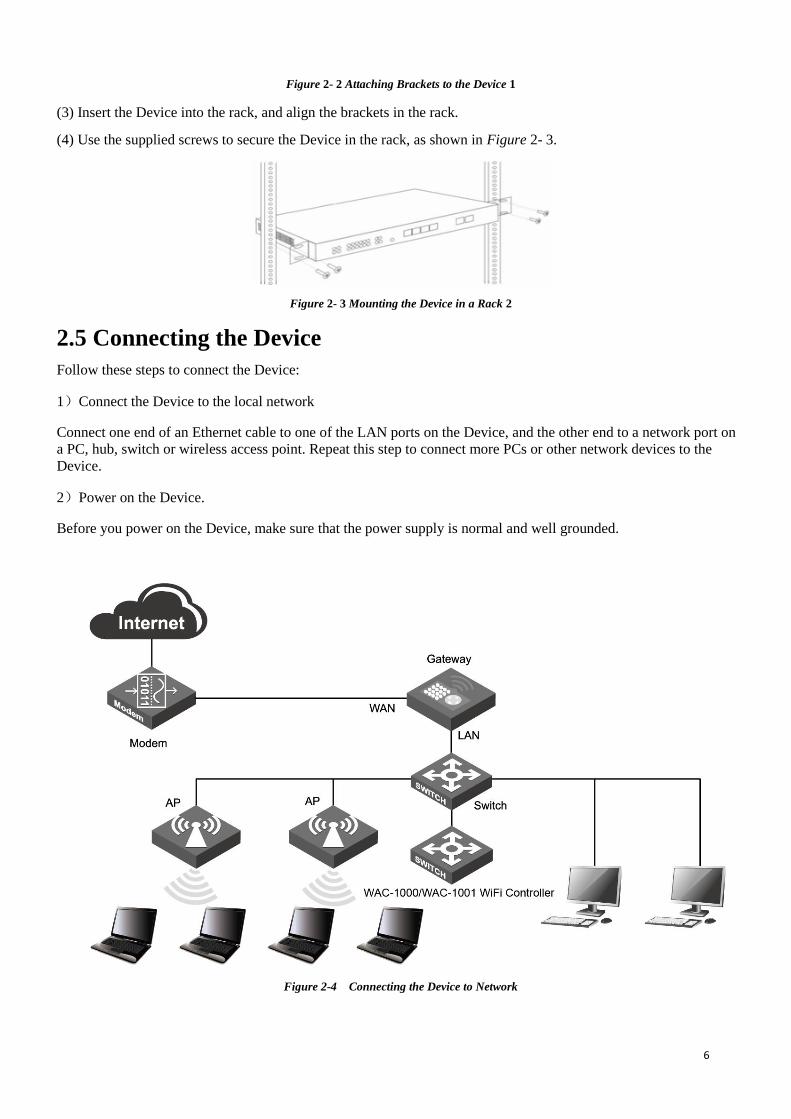
Figure 2- 2 Attaching Brackets to the Device 1
(3) Insert the Device into the rack, and align the brackets in the rack.
(4) Use the supplied screws to secure the Device in the rack, as shown in Figure 2- 3.
Figure 2- 3 Mounting the Device in a Rack 2
2.5 Connecting the Device
Follow these steps to connect the Device:
1)Connect the Device to the local network
Connect one end of an Ethernet cable to one of the LAN ports on the Device, and the other end to a network port on
a PC, hub, switch or wireless access point. Repeat this step to connect more PCs or other network devices to the
Device.
2)Power on the Device.
Before you power on the Device, make sure that the power supply is normal and well grounded.
Figure 2-4 Connecting the Device to Network
7
Chapter 3 Logging to the Device This chapter describes how to configure TCP/IP settings on your computer, and how to login to the Device. In
addition, it briefly describes the layout of the Device’s Web interface.
3.1 Configuring Your Computer
To configure the Device via Web UI, you need to properly configure TCP/IP settings on the computer that you use to
manage the Device. To do this, follow these steps:
Step 1 Connect the computer to a LAN port of the Device, or connect the computer to the Device wirelessly.
Step 2 Install TCP/IP protocol on your computer. If it is already installed, please skip this step.
Step 3 Do one the following to configure TCP/IP settings on your computer:
① If you want to want to set the IP address and other settings manually, select Use the following IP
address, set the IP address to an unused one in the 192.168.1.0/24 subnet, subnet mask to 255.255.255.0,
and default gateway to 192.168.1.1. Note: the Device’s default LAN IP address is 192.168.1.1 with a
subnet mask of 255.255.255.0.
② If a DHCP server is available on your network, and you want IP settings to be assigned automatically,
select Obtain an IP address automatically.
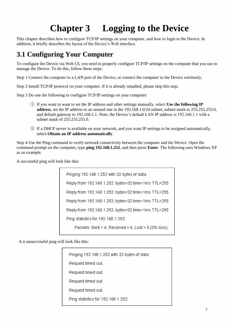
Step 4 Use the Ping command to verify network connectivity between the computer and the Device. Open the
command prompt on the computer, type ping 192.168.1.252, and then press Enter. The following uses Windows XP
as an example.
A successful ping will look like this:
A n unsuccessful ping will look like this:
8
If the Ping command is successful, the connection between the computer and the Device is working properly. If the
Ping command fails, please do the following:
① Check physical connection: Verify that the LAN LED on the Device and the LED on your computer’s
network card are lit.
② Check TCP/IP settings: Verify that your computer is on the same subnet as the Device’s LAN interface.
E.g., if the Device’s LAN IP address is 192.168.1.1 (default), the computer’s IP address must be an unused IP
address in the 192.168.1.0/24 subnet.
3.2 Logging to the Device
No matter what operating system is installed on your computer, such as, MS Windows, Macintosh, UNIX, or Linux,
and so on, you can configure the Device through the Web browser (e.g., Internet Explorer, Firefox).
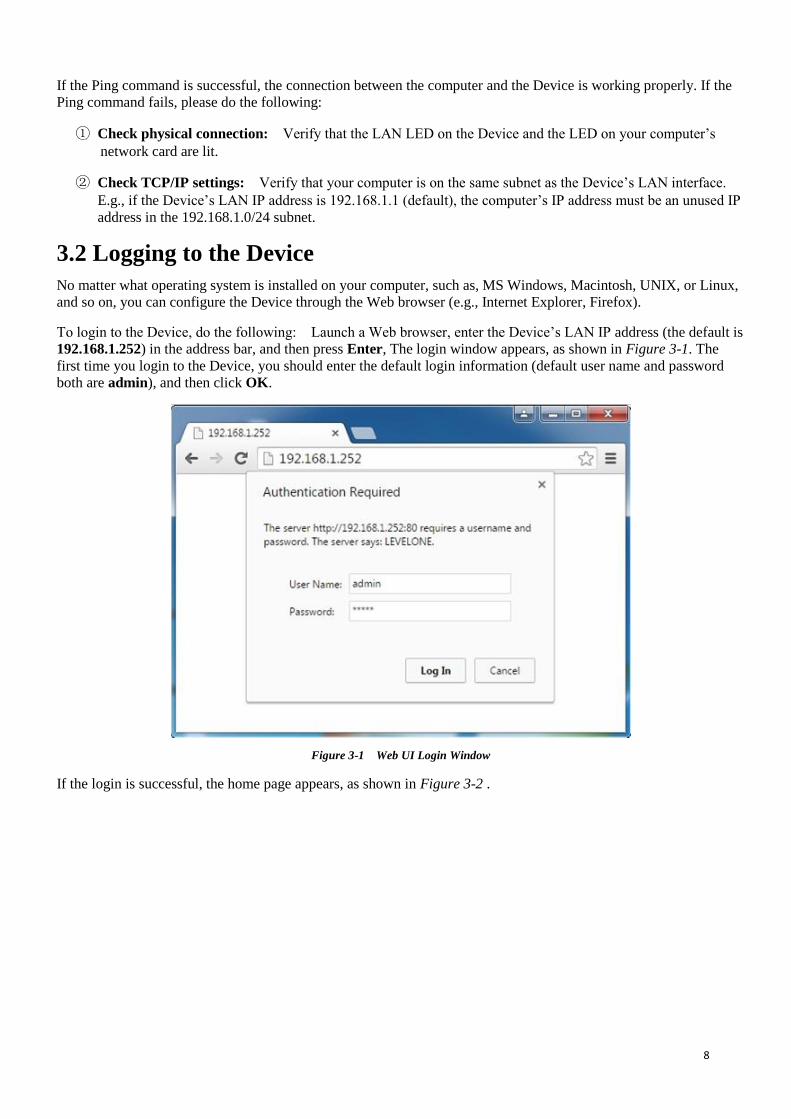
To login to the Device, do the following: Launch a Web browser, enter the Device’s LAN IP address (the default is
192.168.1.252) in the address bar, and then press Enter, The login window appears, as shown in Figure 3-1. The
first time you login to the Device, you should enter the default login information (default user name and password
both are admin), and then click OK.
Figure 3-1 Web UI Login Window
If the login is successful, the home page appears, as shown in Figure 3-2 .

9
Figure 3-2 Web UI Home Page
1) The page shows the number of online and offline APs, and the number of wireless users online, click on the icon
and to refresh the number of APs and wireless users online. The icons on the top mean as follows:
: Number of APs online, which means the number of online APs currently in the network.
: Number of APs offline, which means the number of offline APs currently in the network.
: Number of wireless users online, which means the total number of wireless users of AP
accessing to the AC control in the network.
2) There is a main operation page at the bottom of this page, and in the main operation page, you can configure
various functions, view the configuration information and status information and statistics, etc.
If this is the first time for you to log into the device, the main operation page will link directly to the distribution map.
In the next chapter, we will tell how to configure the basic parameters needed for the device to work normally.

10
Chapter 4 Distribution map The distribution map shows the distribution of AP in the architectural plan, so as to manage the AP in a more
effective manner. In the diagram, you can import several architectural plans, edit the AP distribution locations,
view the AP profile, details and other information, detect the AP anomalies, such as interference testing, load
testing, etc., and manage a single unit for AP in the diagram.
Figure 4- 1 Page of distribution map
This page displays AP list and Map Properties on the left side.
AP list: shows the AP information currently online and have not been added to the map, including the MAC
address. Click and drag the AP name to the actual position of the map on the right side, and add the AP to the
map. Note: The AP that has been added to the map will not be displayed in the AP list.
Drawing properties: Show the number of online APs, offline AP, users, and the name, notes, size and other
information of the drawings in the current drawings. Here, the name and note of the drawing can be modified.
Or the current drawing can be saved to the local computer.
The right side of this page is the display interface of the distribution map. With manually addition, all the APs
you manage will be displayed on the map. AP's online status is represented by colors, green means AP online,
while gray means offline AP. Click on the AP icon on the map for single unit management.
: Click to manage the current AP. Please refer to the chapter: AP Settings.
: Click to lock the location of AP on the map.
: Click to delete the current AP on the map.
4.1 Summary
Click on Map → Profile, to display the AP's IP address, MAC address and serial number on the map.

11
Figure 4- 2 AP Summary
4.2 Details
Click Map→Details, to display the AP's device name, IP address, MAC address, serial number, online client,
channel and SSID on the map.
Figure 4- 3 AP Details
Device Name: Name of AP.
IP address: IP address of AP.
MAC address: AP's MAC address.
Serial number: AP's serial number.
Online client: The number of clients accessed to the AP.
Channel: Show the current wireless network frequency where AP works.
SSID: SSID (Service Set Identification) is used to uniquely identify a string of wireless network, and is case
sensitive.
12
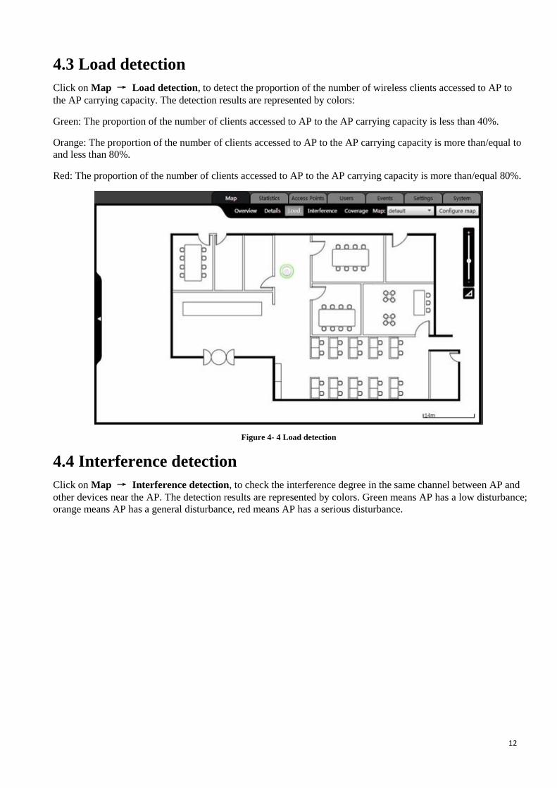
4.3 Load detection
Click on Map → Load detection, to detect the proportion of the number of wireless clients accessed to AP to
the AP carrying capacity. The detection results are represented by colors:
Green: The proportion of the number of clients accessed to AP to the AP carrying capacity is less than 40%.
Orange: The proportion of the number of clients accessed to AP to the AP carrying capacity is more than/equal to
and less than 80%.
Red: The proportion of the number of clients accessed to AP to the AP carrying capacity is more than/equal 80%.
Figure 4- 4 Load detection
4.4 Interference detection
Click on Map → Interference detection, to check the interference degree in the same channel between AP and
other devices near the AP. The detection results are represented by colors. Green means AP has a low disturbance;
orange means AP has a general disturbance, red means AP has a serious disturbance.

13
Figure 4- 5 Interference detection
4.5 Overlay Plots
Click on Map → Overlay Plot, to view the coverage area of AP wireless signal. On the map, the coverage area
of the AP is displayed by a circle with the AP icon as the center of a circle.
Figure 4- 6 AP Overlay Plot
Before viewing the coverage area chart of AP for the first time, it is required to set the scale of the map. The steps
are as follows:
Click , draw a line on the map, click Next, and input the actual distance of the straight line drawn on the
drawing in the pop-up dialog box, and click Save.
14
Figure 4- 7 Coverage distance of map
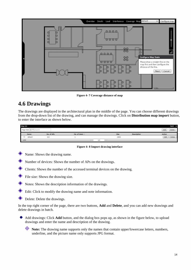
4.6 Drawings
The drawings are displayed in the architectural plan in the middle of the page. You can choose different drawings
from the drop-down list of the drawing, and can manage the drawings. Click on Distribution map import button,
to enter the interface as shown below.
Figure 4- 8 Import drawing interface
Name: Shows the drawing name.
Number of devices: Shows the number of APs on the drawings.
Clients: Shows the number of the accessed terminal devices on the drawing.
File size: Shows the drawing size.
Notes: Shows the description information of the drawings.
Edit: Click to modify the drawing name and note information.
Delete: Delete the drawings.
In the top right corner of the page, there are two buttons, Add and Delete, and you can add new drawings and
delete drawings in batch.
Add drawings: Click Add button, and the dialog box pops up, as shown in the figure below, to upload
drawings and enter the name and description of the drawing.
Note: The drawing name supports only the names that contain upper/lowercase letters, numbers,
underline, and the picture name only supports JPG format.

15
Figure 4- 9 Drawings import
Delete drawings in batch: Check the multiple drawings to be deleted, and click Delete button in the top right side
of the page.
16
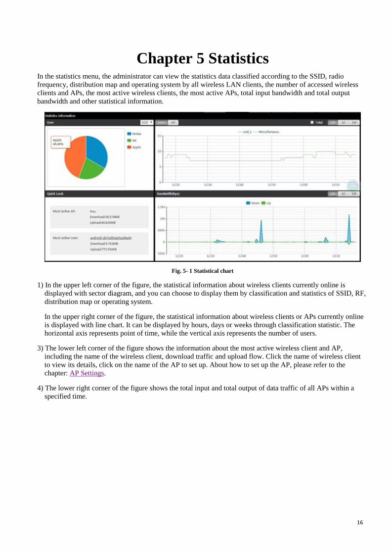
Chapter 5 Statistics In the statistics menu, the administrator can view the statistics data classified according to the SSID, radio
frequency, distribution map and operating system by all wireless LAN clients, the number of accessed wireless
clients and APs, the most active wireless clients, the most active APs, total input bandwidth and total output
bandwidth and other statistical information.
Fig. 5- 1 Statistical chart
1) In the upper left corner of the figure, the statistical information about wireless clients currently online is
displayed with sector diagram, and you can choose to display them by classification and statistics of SSID, RF,
distribution map or operating system.
In the upper right corner of the figure, the statistical information about wireless clients or APs currently online
is displayed with line chart. It can be displayed by hours, days or weeks through classification statistic. The
horizontal axis represents point of time, while the vertical axis represents the number of users.
3) The lower left corner of the figure shows the information about the most active wireless client and AP,
including the name of the wireless client, download traffic and upload flow. Click the name of wireless client
to view its details, click on the name of the AP to set up. About how to set up the AP, please refer to the
chapter: AP Settings.
4) The lower right corner of the figure shows the total input and total output of data traffic of all APs within a
specified time.

17
Chapter 6 Device
6.1 AP Controller
WAC-1000 / WAC-1001 can implement configuration, management, and monitoring of the entire wireless
network in a centralized manner. AP management includes: Issuance software, issuance configuration,
modification of relevant parameters, etc.
WAC-1000 / WAC-1001 and AP can penetrate three layers of network devices between them for mutual
discovery. WAC-1000 / WAC-1001 can normally manage the AP found by the network at the second and third
layer.
This chapter mainly introduces the related concepts about AP centralized management and AP centralized
management functions, including: AP management, distributed service area, configuration of AP RF templates,
AP configuration templates, AP software management, etc.
6.1.1 AP Controller Overview
6.1.1.1 Terminology
Client: A PC, laptop, or other terminals with a wireless Network Interface Card.
STA (station): is a wireless network devices in the network node
WLAN (Wireless Local Area Network): A WLAN is a type of local area network that uses high frequency
radio waves rather than wires to transmit data.
AC (Access Controller): An AC, also known as WLAN controller, is a network device that is used to control and
manage access points in the network.
AP (Access Point): An AP is a network device that acts as a base station for the wireless LAN, and acts as a
bridge between wired and wireless networks.
Fat AP:A standalone AP that independently controls and manages wireless clients.
Fit AP:A simple AP that relies on WLAN controller to control and manage wireless clients.
The access points in Fit AP mode can retrieve firmware and configuration file from the WLAN controller.
Intra-Controller Roaming: Intra-controller roaming occurs when a wireless client roams between APs managed
by the same WLAN controller.
Layer 2 Roaming: Layer 2 roaming occurs when a wireless client roams between APs on the same subnet and
VLAN.
6.1.1.2 Working Principle
For the implementation of Fit AP + WAC-1000 / WAC-1001 solution, the first and crucial step is the issue of Fit
AP's registration on the three-layer switch, and the WAC-1000 / WAC-1001 can manage Fit AP only after Fit AP
is successful in registration. In the practical applications, it is common for WAC-1000 / WAC-1001+Fit AP to
register by crossing three-layer network. Our device has three ways of implementation: the first is the DNS mode,
which requires the support from DNS, DHCP Server, and is relatively complex; the second is the DHCP
Option43 attribute mode, that is, using the Option43 attribute of the DHCP Server; the third is to configure the
WAC-1000 / WAC-1001 address on AP, and this method is relatively simple.
18
When the wireless controller WAC-1000 / WAC-1001 is connected with the Fit AP by crossing three-layer
network, the Option 43 mode is used; when Fit AP is connected to the wireless controller by crossing three-layer
network, Fit AP can directly obtain the IP address of the wireless controller through the Option 43 attribute of
DHCP, thus completing the registration on the wireless controller. The specific process is shown in the figure
below:
Figure 6- 1 WAC-1000 / WAC-1001 and AP centralized manager communicate on the second floor
When the Fit AP and the wireless controller cross three layers of network connection, the registration procedure
of the Fit AP in the wireless controller through the Option 43 attribute of DHCP server is as follows:
1) Fit AP obtains IP address, option 43 attribute (the attribute carries the IP address of the three-layer switches)
through the DHCP server.
2) Fit AP will obtain the IP address of three-layer switch from the option 43 attribute, and then sends the unicast
discovery request to the wireless controller.
3) The wireless controller of the wireless switch that receives the discovery request packet will check if the Fit AP
has the access to this machine, and answers that it discovers a response if any.
4) Fit AP downloads the latest version of software from wireless controller of the wireless switch.
5) Fit AP downloads the latest configuration from the wireless controller.
6) Fit AP begins to work normally to exchange of user data packets with the wireless controller.
Tip:
(1) In the process of device operation, while the configuration file is modified on the AP, for instance, it joins in a
service area, WAC-1000 / WAC-1001 will save the modified configuration file locally and send it to AP, and the
configuration file will be deleted after WAC-1000 / WAC-1001 powers off.
(2) WAC-1000 / WAC-1001 will delete the configuration file saved before after recovering the AP to its factory
configuration remotely.
(3) The AP uploaded configuration file will not be displayed in the configuration file list.
(4) AP can start transmitting user data immediately after successfully obtaining the software, configuration file.
19
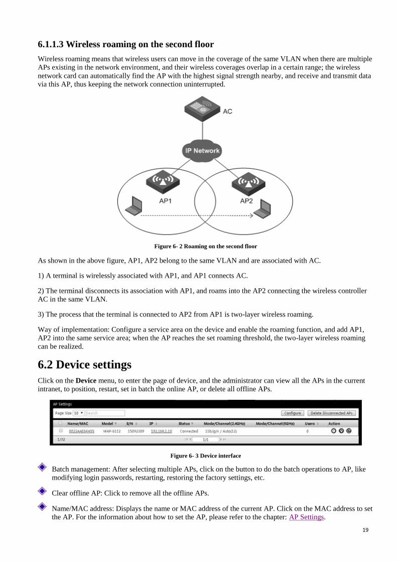
6.1.1.3 Wireless roaming on the second floor
Wireless roaming means that wireless users can move in the coverage of the same VLAN when there are multiple
APs existing in the network environment, and their wireless coverages overlap in a certain range; the wireless
network card can automatically find the AP with the highest signal strength nearby, and receive and transmit data
via this AP, thus keeping the network connection uninterrupted.
Figure 6- 2 Roaming on the second floor
As shown in the above figure, AP1, AP2 belong to the same VLAN and are associated with AC.
1) A terminal is wirelessly associated with AP1, and AP1 connects AC.
2) The terminal disconnects its association with AP1, and roams into the AP2 connecting the wireless controller
AC in the same VLAN.
3) The process that the terminal is connected to AP2 from AP1 is two-layer wireless roaming.
Way of implementation: Configure a service area on the device and enable the roaming function, and add AP1,
AP2 into the same service area; when the AP reaches the set roaming threshold, the two-layer wireless roaming
can be realized.
6.2 Device settings
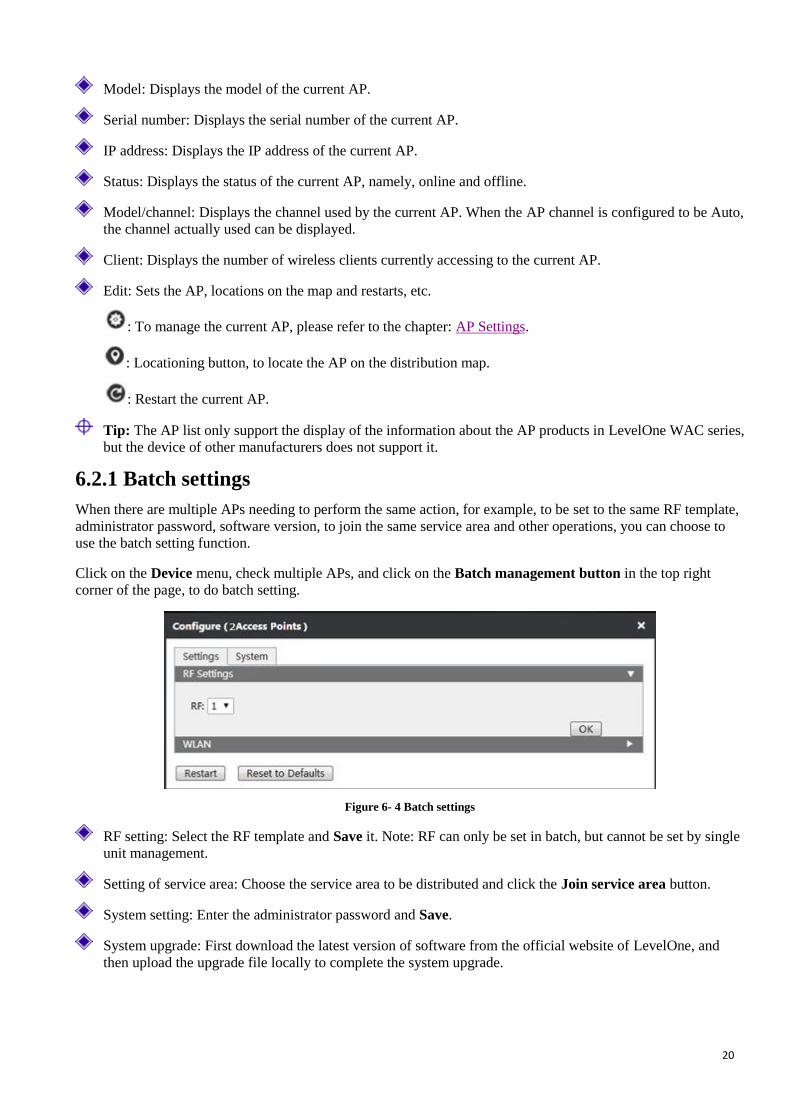
Click on the Device menu, to enter the page of device, and the administrator can view all the APs in the current
intranet, to position, restart, set in batch the online AP, or delete all offline APs.
Figure 6- 3 Device interface
Batch management: After selecting multiple APs, click on the button to do the batch operations to AP, like
modifying login passwords, restarting, restoring the factory settings, etc.
Clear offline AP: Click to remove all the offline APs.
Name/MAC address: Displays the name or MAC address of the current AP. Click on the MAC address to set
the AP. For the information about how to set the AP, please refer to the chapter: AP Settings.
20
Model: Displays the model of the current AP.
Serial number: Displays the serial number of the current AP.
IP address: Displays the IP address of the current AP.
Status: Displays the status of the current AP, namely, online and offline.
Model/channel: Displays the channel used by the current AP. When the AP channel is configured to be Auto,
the channel actually used can be displayed.
Client: Displays the number of wireless clients currently accessing to the current AP.
Edit: Sets the AP, locations on the map and restarts, etc.
: To manage the current AP, please refer to the chapter: AP Settings.
: Locationing button, to locate the AP on the distribution map.
: Restart the current AP.
Tip: The AP list only support the display of the information about the AP products in LevelOne WAC series,
but the device of other manufacturers does not support it.
6.2.1 Batch settings
When there are multiple APs needing to perform the same action, for example, to be set to the same RF template,
administrator password, software version, to join the same service area and other operations, you can choose to
use the batch setting function.
Click on the Device menu, check multiple APs, and click on the Batch management button in the top right
corner of the page, to do batch setting.
Figure 6- 4 Batch settings
RF setting: Select the RF template and Save it. Note: RF can only be set in batch, but cannot be set by single
unit management.
Setting of service area: Choose the service area to be distributed and click the Join service area button.
System setting: Enter the administrator password and Save.
System upgrade: First download the latest version of software from the official website of LevelOne, and
then upload the upgrade file locally to complete the system upgrade.
21
6.2.2 AP Settings
Do personalized settings for each AP. Click on behind the AP name to be set, view the details of the AP, set
the information about the client, system of AP.
6.2.2.1 Details
In the AP list, click the Name/MAC address of AP, to show the AP details interface, in which you can view the
information about the system, trends statistics, radio frequency of the current AP.
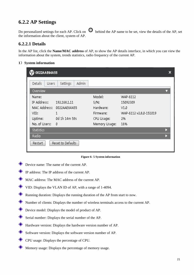
1) System information
Figure 6- 5 System information
Device name: The name of the current AP.
IP address: The IP address of the current AP.
MAC address: The MAC address of the current AP.
VID: Displays the VLAN ID of AP, with a range of 1-4094.
Running duration: Displays the running duration of the AP from start to now.
Number of clients: Displays the number of wireless terminals access to the current AP.
Device model: Displays the model of product of AP.
Serial number: Displays the serial number of the AP.
Hardware version: Displays the hardware version number of AP.
Software version: Displays the software version number of AP.
CPU usage: Displays the percentage of CPU.
Memory usage: Displays the percentage of memory usage.

22
2) Trend statistics
View the number of users accessing to the current AP at the time points, wireless throughput, packet loss rate and
packet error ratio.
Wireless throughput: The wireless upload, download rate of the current AP.
Packet loss rate: Refers to the ratio of the lost error packets to the transmitted data sets in the process of
transmitting data packets.
Packet error ratio: Refers to the ratio of the received error packets to the transmitted data sets in the process of
transmitting data packets.
Figure 6 - 6 Trend statistics
3) RF Information
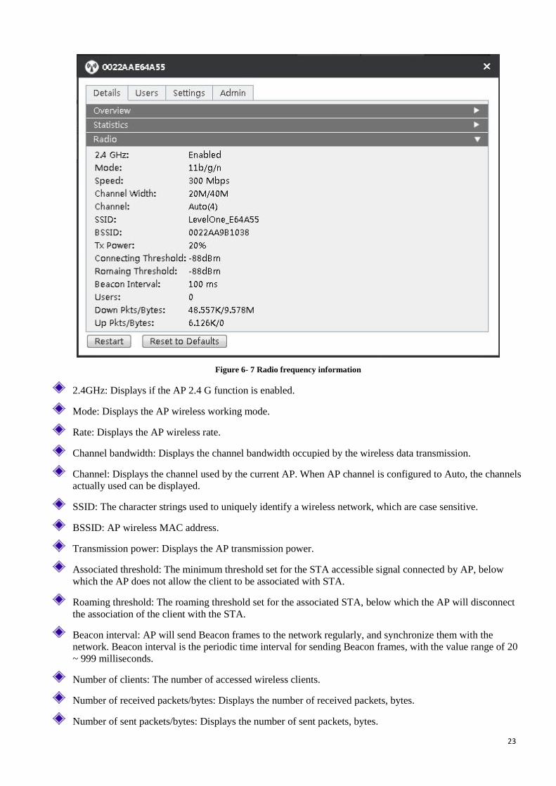
23
Figure 6- 7 Radio frequency information
2.4GHz: Displays if the AP 2.4 G function is enabled.
Mode: Displays the AP wireless working mode.
Rate: Displays the AP wireless rate.
Channel bandwidth: Displays the channel bandwidth occupied by the wireless data transmission.
Channel: Displays the channel used by the current AP. When AP channel is configured to Auto, the channels
actually used can be displayed.
SSID: The character strings used to uniquely identify a wireless network, which are case sensitive.
BSSID: AP wireless MAC address.
Transmission power: Displays the AP transmission power.
Associated threshold: The minimum threshold set for the STA accessible signal connected by AP, below
which the AP does not allow the client to be associated with STA.
Roaming threshold: The roaming threshold set for the associated STA, below which the AP will disconnect
the association of the client with the STA.
Beacon interval: AP will send Beacon frames to the network regularly, and synchronize them with the
network. Beacon interval is the periodic time interval for sending Beacon frames, with the value range of 20
~ 999 milliseconds.
Number of clients: The number of accessed wireless clients.
Number of received packets/bytes: Displays the number of received packets, bytes.
Number of sent packets/bytes: Displays the number of sent packets, bytes.
24
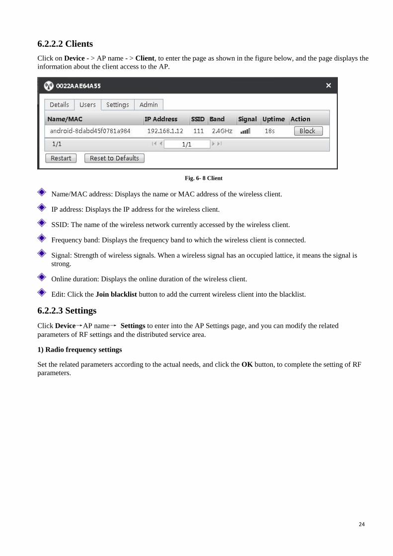
6.2.2.2 Clients
Click on Device - > AP name - > Client, to enter the page as shown in the figure below, and the page displays the
information about the client access to the AP.
Fig. 6- 8 Client
Name/MAC address: Displays the name or MAC address of the wireless client.
IP address: Displays the IP address for the wireless client.
SSID: The name of the wireless network currently accessed by the wireless client.
Frequency band: Displays the frequency band to which the wireless client is connected.
Signal: Strength of wireless signals. When a wireless signal has an occupied lattice, it means the signal is
strong.
Online duration: Displays the online duration of the wireless client.
Edit: Click the Join blacklist button to add the current wireless client into the blacklist.
6.2.2.3 Settings
Click Device→AP name→ Settings to enter into the AP Settings page, and you can modify the related
parameters of RF settings and the distributed service area.
1) Radio frequency settings
Set the related parameters according to the actual needs, and click the OK button, to complete the setting of RF
parameters.

25
Figure 6- 9 Radio frequency settings
Enabling 2.4 GHz frequency band: Checking it means to enable the 2.4 GHz frequency band.
Channel: This parameter is used to select the frequency band in which the wireless network works. The
wireless devices in the same frequency band will interfere with each other. If there are multiple wireless
devices around the AP, please select a frequency different from that of other wireless devices when setting
the channel.
Mode: Set the wireless work mode of AP. It is recommend to use the 11 b/g/n mode.
Wireless rate: Select the AP to use the wireless data transmission rate.
Wireless transmission rate: Select the AP to use the transmission power for wireless data transmission.
Beacon interval: AP will send Beacon (Beacon) frames to the network regularly, and synchronize them with
the network. Beacon interval is the periodic time interval for sending Beacon frames, with the value range of
20 ~ 999 milliseconds.
Enabling thresholds: Check it to enable this feature. Only checking this option can the associated threshold
and roaming threshold be set.
Associated threshold: The minimum threshold set for the STA accessible signal connected by AP, below
which the AP does not allow the client to be associated with STA.
Roaming threshold: The roaming threshold set for the associated STA, below which the AP will disconnect
the association of the client with the STA.
Roaming means that the wireless client can detect other devices with strong wireless signal and access to them
when it leaves the coverage area of the current AP signal. Threshold refers to the minimum threshold for the AP
signal access. When signal strength is lower than the set threshold, the roaming function is enabled.
2) Setting of service area
Check the service area to be distributed, and click Join service area button, to distribute a service area for the
current AP. Note: One AP can distribute at most four service areas.
26
Figure 6- 10 Setting of service area
Service area name: Displays the name of the service area.
SSID: Displays the name of wireless network.
Type: Displays the application type.
Frequency band: Supports two frequency bands, 2.4 G / 5 G, in which ALL means that two frequency bands
of the service area will be distributed.
VLAN ID: Displays the VLAN value, which is between 1-4094.
Address pool: Displays the name of the address pool. For the details of setting the beginning and end address
of the address pool, please refer to the chapter: VLAN Settings.
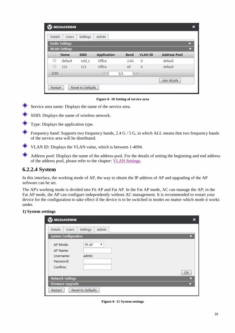
6.2.2.4 System
In this interface, the working mode of AP, the way to obtain the IP address of AP and upgrading of the AP
software can be set.
The AP's working mode is divided into Fit AP and Fat AP. In the Fat AP mode, AC can manage the AP; in the
Fat AP mode, the AP can configure independently without AC management. It is recommended to restart your
device for the configuration to take effect if the device is to be switched in modes no matter which mode it works
under.
1) System settings
Figure 6- 11 System settings

27
System mode: AP working mode. There are two modes: Fat AP and Fit AP.
Device name: Custom AP name.
User name: Displays the name of the currently logged administrator.
Password: Custom password.
Confirming password: Enter the password again.
2) Network settings
Set the way to obtain the IP address of AP, including DHCP (dynamic obtaining) or static configuration.
Figure 6- 12 Network settings
3) Software upgrade
In the software upgrade interface, you can view the information about the currently running version, or can update
system version. First download the latest software from the LevelOne website, and then click Upgrade button for
system upgrade.
Figure 6- 13 Software upgrade diagram

28
Chapter 7 Users On the user page, the administrator can view all the wireless clients in the intranet. Click Online, Offline,
Blacklist button to respectively manage the clients in different states.
7.1 Setting online
To setup the online clients. In the user page, click the Export button in the top right corner to export the list and
detailed information of the wireless clients currently online. Check multiple wireless clients, and click on the Join
blacklist button in the top right corner, to join the wireless clients in the blacklist.
Figure 7- 1 User online interface
Name/MAC address: The name/MAC address of wireless clients.
Operating systems: The operating system used by wireless clients. Such as Windows, IOS, Android, etc.
IP address: IP address of the wireless client.
Access point: Displays the name of the AP accessed by the wireless client.
SSID: Displays the name of the wireless network accessed by the wireless client.
Frequency band: Displays the frequency bands accessed by the wireless client.
Signal quality: Displays the strength level of the current wireless signal. Occupied lattice means strong
signals.
Wireless rate: Displays the wireless rate of wireless clients.
Download/Upload rate: Displays the current upload / download rate of the wireless client.
Online duration: Displays the online duration of the wireless client.
Edit: Click Join blacklist button to add a wireless client into the blacklist.
7.2 Offline settings
To add the offline clients into the blacklists and other settings. Under this page, you can view the MAC address,
access points, download/upload, online time and last access time of offline wireless clients, or can add the offline
wireless clients into the blacklist.
Figure 7- 2 Offline interface

29
7.3 Blacklist settings
To remove the wireless clients from the blacklist and other settings. Under this page, you can view such
information as the name of the blacklist user/MAC address and the time of being pulled into the blacklist or can
remove the blacklist.
Figure 7- 3 Blacklist interface
30
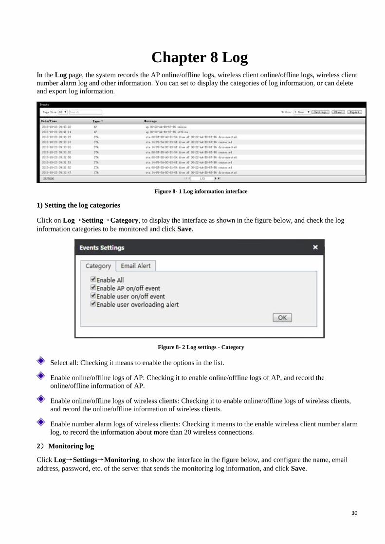
Chapter 8 Log In the Log page, the system records the AP online/offline logs, wireless client online/offline logs, wireless client
number alarm log and other information. You can set to display the categories of log information, or can delete
and export log information.
Figure 8- 1 Log information interface
1) Setting the log categories
Click on Log→Setting→Category, to display the interface as shown in the figure below, and check the log
information categories to be monitored and click Save.
Figure 8- 2 Log settings - Category
Select all: Checking it means to enable the options in the list.
Enable online/offline logs of AP: Checking it to enable online/offline logs of AP, and record the
online/offline information of AP.
Enable online/offline logs of wireless clients: Checking it to enable online/offline logs of wireless clients,
and record the online/offline information of wireless clients.
Enable number alarm logs of wireless clients: Checking it means to the enable wireless client number alarm
log, to record the information about more than 20 wireless connections.
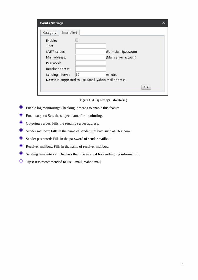
2) Monitoring log
Click Log→Settings→Monitoring, to show the interface in the figure below, and configure the name, email
address, password, etc. of the server that sends the monitoring log information, and click Save.
31
Figure 8- 3 Log settings - Monitoring
Enable log monitoring: Checking it means to enable this feature.
Email subject: Sets the subject name for monitoring.
Outgoing Server: Fills the sending server address.
Sender mailbox: Fills in the name of sender mailbox, such as 163. com.
Sender password: Fills in the password of sender mailbox.
Receiver mailbox: Fills in the name of receiver mailbox.
Sending time interval: Displays the time interval for sending log information.
Tips: It is recommended to use Gmail, Yahoo mail.
32
Chapter 9 Settings This chapter describes how to configure service areas, radio frequency template, load balancing, software version,
etc. on the WAC-1000 / WAC-1001, and these configurations can be distributed to the AP as a template.
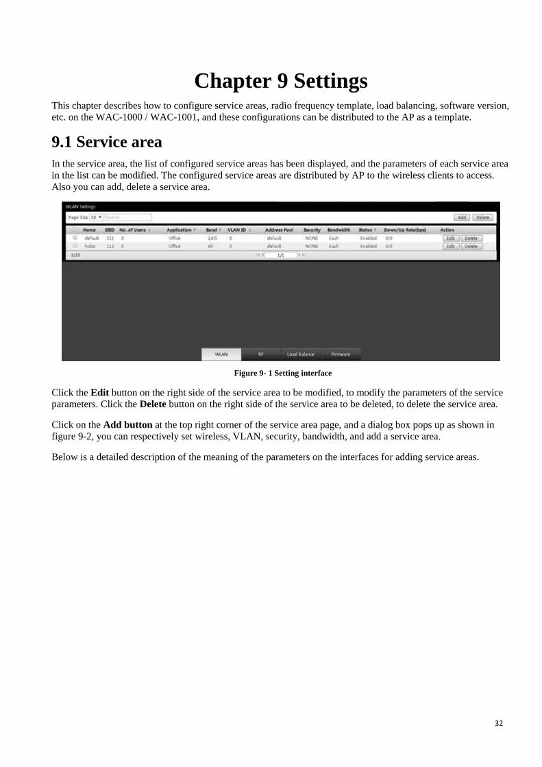
9.1 Service area
In the service area, the list of configured service areas has been displayed, and the parameters of each service area
in the list can be modified. The configured service areas are distributed by AP to the wireless clients to access.
Also you can add, delete a service area.
Figure 9- 1 Setting interface
Click the Edit button on the right side of the service area to be modified, to modify the parameters of the service
parameters. Click the Delete button on the right side of the service area to be deleted, to delete the service area.
Click on the Add button at the top right corner of the service area page, and a dialog box pops up as shown in
figure 9-2, you can respectively set wireless, VLAN, security, bandwidth, and add a service area.
Below is a detailed description of the meaning of the parameters on the interfaces for adding service areas.

33
9.1.1 Wireless settings
Figure 9- 2 Wireless settings
Service area name: Defines the name of the service area.
SSID: (Service Set Identification) defines the SSID of the service area, and a string for uniquely identifying a
wireless network, case sensitive.
Main use: Employees, voice, visitors, etc. can be selected. The access levels of these three from high to low
are as follows: Employees, voice, visitors.
Broadcast filtering: Choose the way to broadcast packet filtering.
DTIM interval: Selects the number of beacon intervals between 1 and 10 beacons.
Multicast transmission optimization: Selects whether to enable optimization of multicast transmission.
Dynamic multicast transmission: Selects to enable optimal dynamic multicast transmission or not.
DMO channel using threshold value: The higher the percentage is, the higher the priority is.
2.4GHz: Able to stably reach the Internet by setting the minimum and maximum transmission rate of
2.4GHz.
5GHz: Able to stably reach the Internet by setting the minimum and maximum transmission rate of 5GHz.
Air interface: Checking it to enable this feature.
Each radio: Checking it to enable the radio function.
Background WMM sharing: Sets the percentage of the background WMM share, in order to ensure
establishing a stable connection with network resources, and providing a high quality data network
connection performance.
34
Most effective WMM sharing: Sets the percentage of the most effective WMM sharing, in order to ensure
establishing a stable connection with network resources, and providing a high quality network connecting
performance.
Video WMM sharing: Sets the percentage of the video WMM sharing, in order to ensure establishing a
stable connection with network resources, and providing a high quality video network connecting
performance.
Voice WMM sharing: Sets the percentage of the language WMM sharing, in order to ensure establishing a
stable connection with network resources, and providing high quality voice network connecting performance.
Content filtering: Checking it to enable this feature.
Frequency band: Selects the frequency band that the service area supports. 2.4 GHz, 5 GHz, ALL are
available.
Inactivity timeout: The default is 100 seconds.
Hide SSID: Checking it to enable this feature. After hiding SSID, access is possible only when the SSID
name is manually entered for search and the wireless network is connected, or before enabling this feature,
you have already connect to the wireless network, so it can be automatically accessed.
Limit of the maximum number of clients: Controls the number of clients accessed by AP. It is recommended
not to exceed 20, 0 means no restriction.
Limit of local detection request: Set the threshold for local detection.
Automatic update: Automatically checked by default. It means the new service area will be automatically
distributed to all the online APs. When the number of automatically updated service areas exceeds 4, the new
service areas will not be automatically distributed.
Client Isolation: Isolates the mutual access between the connected terminal devices.
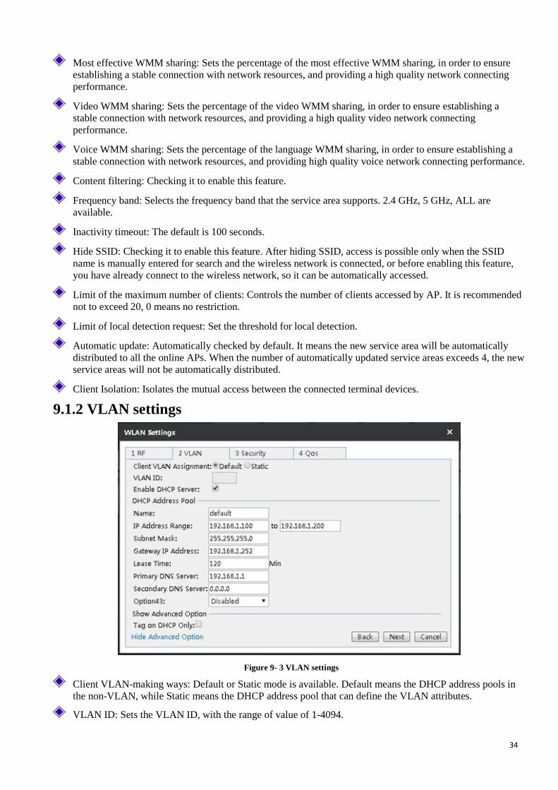
9.1.2 VLAN settings
Figure 9- 3 VLAN settings
Client VLAN-making ways: Default or Static mode is available. Default means the DHCP address pools in
the non-VLAN, while Static means the DHCP address pool that can define the VLAN attributes.
VLAN ID: Sets the VLAN ID, with the range of value of 1-4094.

35
Enable the DHCP server of the device: Checking it to mean the DHCP server is enabled on this device.
Name: Name of custom address pool.
IP address range: Sets the range for Intranet users to obtain the IP address.
Subnet mask/gateway address: The subnet mask/gateway addresses assigned by the DHCP server to the
intranet computers, mobile phones and other clients automatically.
Lease term: The leasing time for the Intranet computers to obtain the IP address assigned by the device (Unit:
Minutes).
Primary DHCP server: The primary DNS server IP address assigned by the DHCP server to the Intranet
computers, mobile phones and clients automatically.
Secondary DNS server: The secondary DNS server IP address assigned by the DHCP server to the Intranet
computers, mobile phones and other clients automatically.
Option43: By modifying the variable length fields of option 43 in the DHCP protocol packets, it is used to
carry the IP address of AC, and let AP analyze the AC address carried by option 43, so it is used for
discovering AC. There are four options, Disable, HEX fixed-length, ASCII indefinite length, Custom.
9.1.3 Security settings
To make access authentication for such clients as computers, mobile phones that want to join the service area,
password authentication and free of authentication are now provided. Password authentication provides three
wireless security mechanisms, namely WEP, WPA/WPA2 and WPA-PSK/WPA2-PSK. The following sections
will introduce the configuration parameters and their meanings.
9.1.3.1 WEP
Figure 9- 4 WEP
Authentication type: When using the WEP encryption mechanism, three options, automatic, open systems,
Shared keys are provided:
Auto: Means that the device can automatically choose Open System or Pre-shared key mode according
to the requests of wireless clients.
Open system: At this point, the wireless clients can pass the authentication and associate with the
wireless devices on the premise of not providing authentication key. To perform data transmission, you
must provide the correct key.
36
Shared key: At this point, the client must provide the correct key to pass the authentication, otherwise it
cannot be associated with the wireless devices, and cannot perform data transmission.
Key format: Two formats, hexadecimal code and ASCII code are provided:
When the hexadecimal code is used, the key characters can be 0 ~ 9, A, B, C, D, E, F.
When the ASCII code is used, the key characters can be all ASCII codes.
Key selection: The user can enter 1 ~ 4 keys according to needs, and these 4 keys can use different key types.
WEP key: Sets the key value, and the length of the key is affected by key types:
When choosing a 64 - bit key, you can input 9 hexadecimal characters or 5 ASCII characters.
When choosing a 128 - bit key, you can input 26 hexadecimal characters or 9 ASCII characters.
Key types: Selects key types, and provides three options, Disable, 64 bits, 128 bits. Among them, Disable
means not to use the current key, but 64 bits, 128 bits, and used to specify the length of the WEP key.
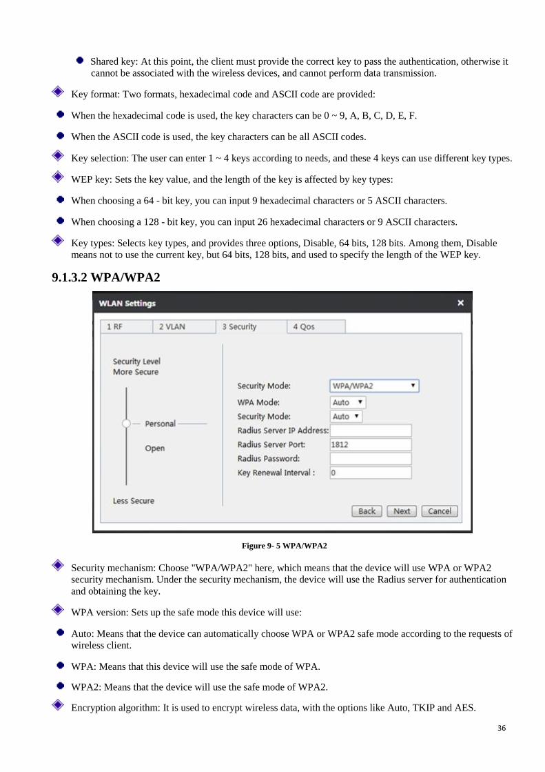
9.1.3.2 WPA/WPA2
Figure 9- 5 WPA/WPA2
Security mechanism: Choose "WPA/WPA2" here, which means that the device will use WPA or WPA2
security mechanism. Under the security mechanism, the device will use the Radius server for authentication
and obtaining the key.
WPA version: Sets up the safe mode this device will use:
Auto: Means that the device can automatically choose WPA or WPA2 safe mode according to the requests of
wireless client.
WPA: Means that this device will use the safe mode of WPA.
WPA2: Means that the device will use the safe mode of WPA2.
Encryption algorithm: It is used to encrypt wireless data, with the options like Auto, TKIP and AES.
37
Auto: Means that the device will automatically choose encryption algorithms according to needs.
TKIP: Means that all wireless data will use TKIP as the encryption algorithm.
AES: Means that all wireless data will use AES as the encryption algorithm.
Radius Server IP: It is the IP address of the Radius server used for identify authentication of the wireless
hosts.
Radius port: The Port number of service used by the Radius server for identifying the authentication of the
wireless hosts.
Radius password: Sets the password for accessing the Radius service.
Key update cycle: It is the timed update cycle used to specify the key. Value range is 60 ~ 86400, in the unit
of seconds. The default value is 3600, which means no update when the value is 0.
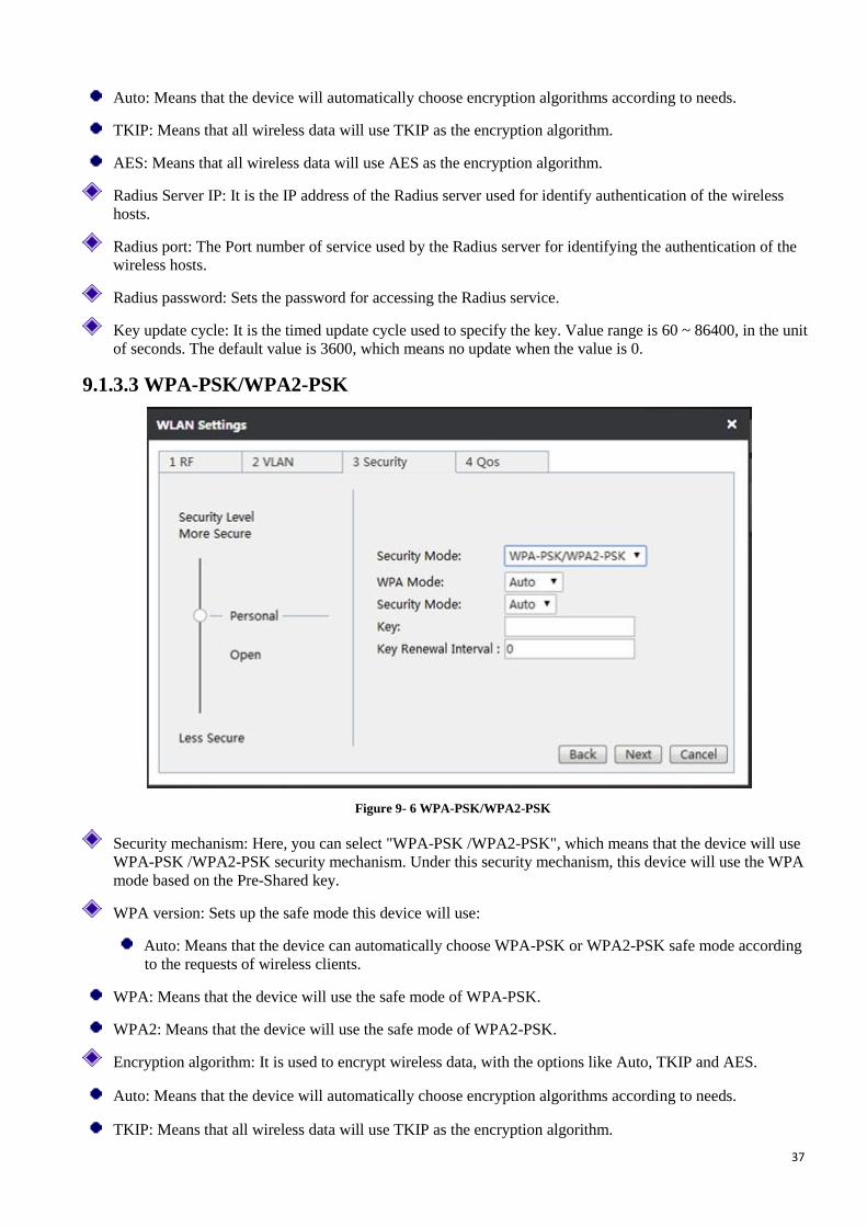
9.1.3.3 WPA-PSK/WPA2-PSK
Figure 9- 6 WPA-PSK/WPA2-PSK
Security mechanism: Here, you can select "WPA-PSK /WPA2-PSK", which means that the device will use
WPA-PSK /WPA2-PSK security mechanism. Under this security mechanism, this device will use the WPA
mode based on the Pre-Shared key.
WPA version: Sets up the safe mode this device will use:
Auto: Means that the device can automatically choose WPA-PSK or WPA2-PSK safe mode according
to the requests of wireless clients.
WPA: Means that the device will use the safe mode of WPA-PSK.
WPA2: Means that the device will use the safe mode of WPA2-PSK.
Encryption algorithm: It is used to encrypt wireless data, with the options like Auto, TKIP and AES.
Auto: Means that the device will automatically choose encryption algorithms according to needs.
TKIP: Means that all wireless data will use TKIP as the encryption algorithm.
38
AES: Means that all wireless data will use AES as the encryption algorithm.
Pre-shared key: The preset initialization key, with the value of 8 ~ 63 characters.
Key update cycle: It is the timed update cycle used to specify the key. Value range is 60 ~ 86400, in the unit
of seconds. The default value is 3600, which means no update when the value is 0.
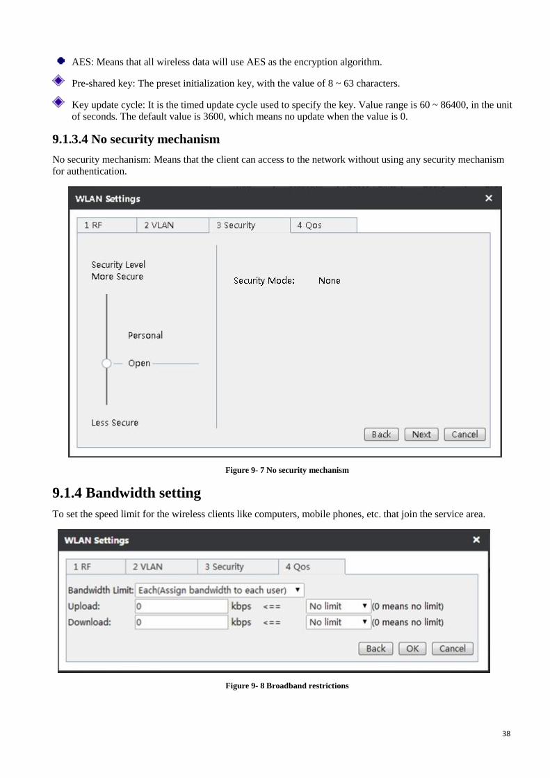
9.1.3.4 No security mechanism
No security mechanism: Means that the client can access to the network without using any security mechanism
for authentication.
Figure 9- 7 No security mechanism
9.1.4 Bandwidth setting
To set the speed limit for the wireless clients like computers, mobile phones, etc. that join the service area.
Figure 9- 8 Broadband restrictions

39
Bandwidth limitation: The available options are divided into exclusive and shared; Exclusive means each IP
address in this range uses the bandwidth; Shared means the IP address in this range shares the bandwidth.
Uplink/downlink bandwidth: Upload speed limit, download speed limit. Here, the maximum upload and
download rate of IP address in this range can be set. 0 means no limitation.
Back: Click to return to the interface at the next higher level.
Finish: Click on the complete configuration.
Cancel: Cancel the configuration information.
9.2 Radio frequency template
Set the radio frequency template for AP to distribute wireless RF parameters. Note: The radio frequency
templates can only be distributed to AP in batch.
The radio frequency template page shows the list of RF templates, in which all the parameters can be modified.
The radio frequency templates can also be deleted or added.
Figure 9- 9 RF template interface
Click the Edit button on the right side of the radio frequency template to be modified, to modify the parameters of
the radio frequency template. Click the Delete button on the right side of the radio frequency template to be
deleted, to delete the radio frequency template.
In the Settings→RF template page, click the Add button, and a dialog box pops up as shown in the figure below,
and you can set the parameters set, and add a radio frequency template. Below is a detailed description of the
meaning of the parameters of the interfaces in adding radio frequency templates.
Figure 9- 10 Radio frequency template
40
Template name: The name of the radio frequency template.
Enable wireless function: Checking it to enable the wireless function of two frequency bands, 2.4 GHz and 5
GHz.
Mode: Chooses the wireless working mode.
Channel: This parameter is used to select frequency bands in which the wireless network works. The wireless
devices in the same frequency will interfere with each other, and if there are multiple wireless devices around
the AP, please select a different frequency from that of other wireless devices in setting channels.
Channel bandwidth: Selects the bandwidth of corresponding channels.
Wireless rate: Selects the wireless transmission rate.
Wireless transmission power: Selects the wireless transmission power.
Beacon interval: AP will send Beacon frames to the network regularly, and synchronize with the network.
Beacon interval is the periodic time interval for sending Beacon frames. Value range is 20~999 milliseconds.
Enable WMM: Checking to enable the WMM function.
Short Guard Interval: Checking it to enable this function.
Short Preamble: Checking it to enable this function.
Interference immunity level: Chooses the level of interference immunity, with a range of 1 to 5.
Channel switching notice number: Selects the number of channel switching notices, ranging 1-9.
Background spectrum monitoring: Checking to enable this function.
Advanced options:
Frequency switching mode: Includes four modes, Disabled, Optimized 5 GHZ, Mandatory 5 GHZ,
Frequency balancing.
Optimized 5GHz: Guides the STA supporting dual frequency to be connected to AP first via 5GHz.
Mandatory 5GHz: For STA that supports dual frequency, only STA is allowed to be connected to AP
through the 5 GHZ radio frequency.
Frequency balancing: AP guides STA to be distributed in balance on the 2.4 GHz and 5 GHz radio
frequencies.
2.4GHz client: Sets the maximum number of wireless clients in the AP 2.4GHz band.
5GHz client: Sets the maximum number of wireless clients in the AP 5GHz band.
9.3 Load balancing
When the covering area overlaps between the APs, these APs can be set up for load balancing, and by setting this
parameter, the wireless clients in the overlapped area can be distributed in balance according to the actual
machine amount of APs, so as to improve the quality of network service. The load balance groups can be
modified, deleted, added, etc.

41
Figure 9-11 Load balancing
Modify load balancing group: Click on the Edit button to modify the current load balancing configuration.
Delete load balancing group: Click on the Delete button behind the corresponding load balancing group.
Add load balancing group: Click on the Add button, and an interface pops up as shown in the following
figure, and you can configure the AP members needing to achieving load balancing.
Figure 9- 12 Load balancing
Enable load balancing: Clicking to check this option can enable the load balancing function.
Load balancing group name: Sets the name of the AP load balancing group.
List of APs available: Displays the basic information of the current AP.
Load balancing group member: Displays the basic information of the APs that have enabled the load
balancing function. (A load balancing group's configuration range is 2 ~ 10 sets of AP.)
9.4 Software management
To manage the versions of AP software. To understand the information of the current AP software version stored
in the memory by viewing the software list, or upload the latest version of the AP software. If the model of the
uploaded software version is the same as that stored in the memory, it will cover the old version.
After checking "Auto upgrade", all the APs in this model will be automatically upgraded in the restarting of AP.
Note: Only when the version of the uploaded software is higher than that of the current AP, the system will
automatically be upgraded. If you want to upgrade an AP or more than one AP, please upgrade the corresponding
AP under the Device menu.
Figure 9- 13 Software management
42
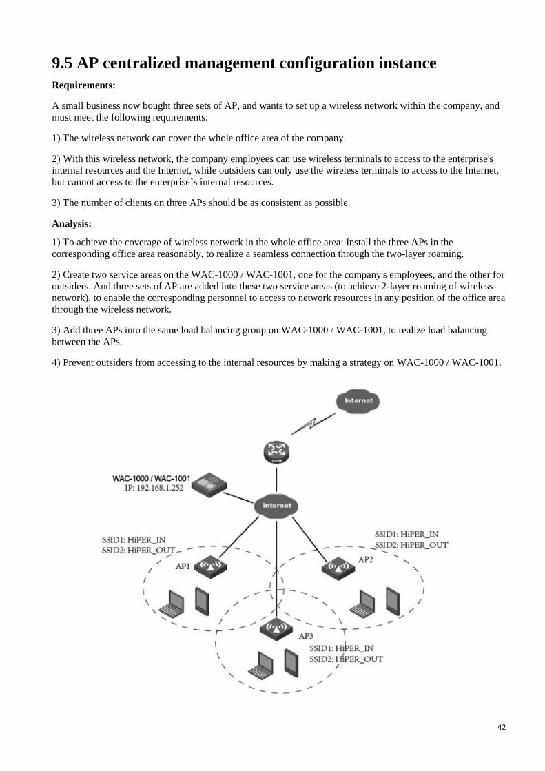
9.5 AP centralized management configuration instance
Requirements:
A small business now bought three sets of AP, and wants to set up a wireless network within the company, and
must meet the following requirements:
1) The wireless network can cover the whole office area of the company.
2) With this wireless network, the company employees can use wireless terminals to access to the enterprise's
internal resources and the Internet, while outsiders can only use the wireless terminals to access to the Internet,
but cannot access to the enterprise’s internal resources.
3) The number of clients on three APs should be as consistent as possible.
Analysis:
1) To achieve the coverage of wireless network in the whole office area: Install the three APs in the
corresponding office area reasonably, to realize a seamless connection through the two-layer roaming.
2) Create two service areas on the WAC-1000 / WAC-1001, one for the company's employees, and the other for
outsiders. And three sets of AP are added into these two service areas (to achieve 2-layer roaming of wireless
network), to enable the corresponding personnel to access to network resources in any position of the office area
through the wireless network.
3) Add three APs into the same load balancing group on WAC-1000 / WAC-1001, to realize load balancing
between the APs.
4) Prevent outsiders from accessing to the internal resources by making a strategy on WAC-1000 / WAC-1001.
43
Figure 9- 14 AP centralized management configuration instance
Configuration steps:
1) Access configuration
Connect the WAC - 1000 / WAC – 1000 in bypass mode of the company network, here, the upper interface
VLAN connected to WAC-1000 / WAC-1001 is VLAN10.
2) Interface configuration
Log in to WAC-1000 / WAC-1001, to configure the LAN port, WAN port of the device, to complete the basic
configuration on the Internet. Here, the LAN port IP address is 192.168.1.252.
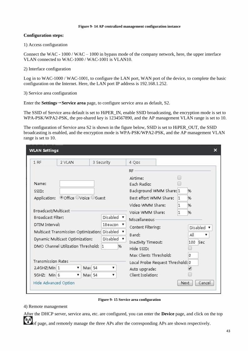
3) Service area configuration
Enter the Settings→Service area page, to configure service area as default, S2.
The SSID of Service area default is set to HiPER_IN, enable SSID broadcasting, the encryption mode is set to
WPA-PSK/WPA2-PSK, the pre-shared key is 1234567890, and the AP management VLAN range is set to 10.
The configuration of Service area S2 is shown in the figure below, SSID is set to HiPER_OUT, the SSID
broadcasting is enabled, and the encryption mode is WPA-PSK/WPA2-PSK, and the AP management VLAN
range is set to 10.
Figure 9- 15 Service area configuration
4) Remote management
After the DHCP server, service area, etc. are configured, you can enter the Device page, and click on the top
of page, and remotely manage the three APs after the corresponding APs are shown respectively.

44
In the remote management page, click on the AP name → Settings → Service settings. After entering the
service area list page, check the service areas whose names are default, S2, and then click the Join service button.
Add other two APs into these two service areas in the same way.
5) AP load balancing
Enter the Settings → Load balancing page, click the Add button, to enter the load balancing group
configuration interface, and check Enable load balancing group, and input the name of load balancing group,
HiPER_NEW, add three APs into the load balancing group, and click Save.
With the above configuration, the enterprise employees can access to the network through HiPER_IN; the
outsiders can access to the network through HiPER_OUT.
9.6 AP centralized management configuration instance (Three
layer management)
9.6.1 Typical environment I (option43/ option60 for the application of the
ACCESS port and 3 layer switches)
1) Demand:
Analyze the WAC-1000 / WAC-1001 address in the AP through the option43 field, and discover AC by three
layers.
VLAN is divided into three parts on the 3-layer switch, VLAN1, VLAN2, VLAN3 respectively, and WAP-6201
is on the access interface to which VLAN2 of the 3-layer switch, and the IP address for VLAN2 virtual interface
is 192.168.2.254. WAP-6111 is on the access interface to which VLAN3 of the 3-layer switch, and the IP address
for VLAN3 virtual interface is 192.168.3.254. The IP address of AC LAN is 192.168.1.252, and the IP for
VLAN1 virtual interface is 192.168.1.254. The pool of the corresponding VLAN is created for the virtual
interface in the VLANs, and the IP address of option43 with the field of WAC-1000 /WAC-1001 is defined. The
dotted decimal format is 192.168.1.252; the dotted hexadecimal format is 0104C0A801FC, here, 01 represents
fixed identifier while 04 represents the character length of 4 bytes. And configure the option60 field format as
ASCII, and the character content as LEVELONE, this is AP supported field.
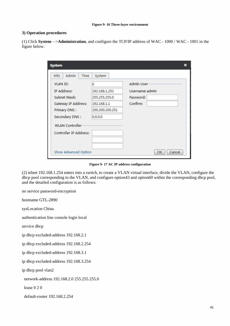
2) Environment topology
45
Figure 9- 16 Three-layer environment
3) Operation procedures
(1) Click System—>Administration, and configure the TCP/IP address of WAC - 1000 / WAC - 1001 in the
figure below.
Figure 9- 17 AC IP address configuration
(2) telnet 192.168.1.254 enters into a switch, to create a VLAN virtual interface, divide the VLAN, configure the
dhcp pool corresponding to the VLAN, and configure option43 and option60 within the corresponding dhcp pool,
and the detailed configuration is as follows:
no service password-encryption
hostname GTL-2890
sysLocation China
authentication line console login local
service dhcp
ip dhcp excluded-address 192.168.2.1
ip dhcp excluded-address 192.168.2.254
ip dhcp excluded-address 192.168.3.1
ip dhcp excluded-address 192.168.3.254
ip dhcp pool vlan2
network-address 192.168.2.0 255.255.255.0
lease 0 2 0
default-router 192.168.2.254
46
dns-server 200.200.200.251 8.8.8.8
option 43 ip 192.168.1.252
option 60 ascii LEVELONE
ip dhcp pool vlan3
network-address 192.168.3.0 255.255.255.0
lease 0 2 0
default-router 192.168.3.254
dns-server 200.200.200.251 8.8.8.8
option 43 hex 0104C0A801FC
option 60 ascii LEVELONE
vlan 1-3
Interface Ethernet1/0/7
switchport access vlan 2
Interface Ethernet1/0/8
switchport access vlan 2
Interface Ethernet1/0/9
switchport access vlan 3
Interface Ethernet1/0/10
switchport access vlan 3
interface Vlan1
ip address 192.168.1.254 255.255.255.0
interface Vlan2
ip address 192.168.2.254 255.255.255.0
interface Vlan3
ip address 192.168.3.254 255.255.255.0
ip route 0.0.0.0/0 192.168.1.252
no login
end
(3) Enter the centralized management list of A WAC-1000 / WAC-1001C, and view WAC-1000 / WAC-1001 to
check if two APs are discovered, and the IP address of the AP are 192.168.2.0 network segment address and
192.168.3.0 network segment address respectively.
(4) Enter the WAC-1000 / WAC-1001 service area page, create a new service area, to be distributed to two sets of
AP, and see if they can take effect.

47
Figure 9- 18 AP management list
48
Chapter 10 System management This chapter introduces the system configuration and related information about WAC-1000 / WAC-1001.
10.1 Information
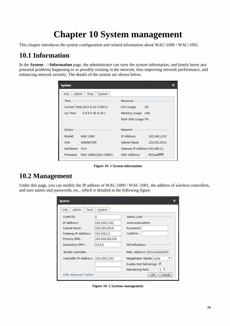
In the System—>Information page, the administrator can view the system information, and timely know any
potential problems happening to or possibly existing in the network, thus improving network performance, and
enhancing network security. The details of the system are shown below.
Figure 10- 1 System information
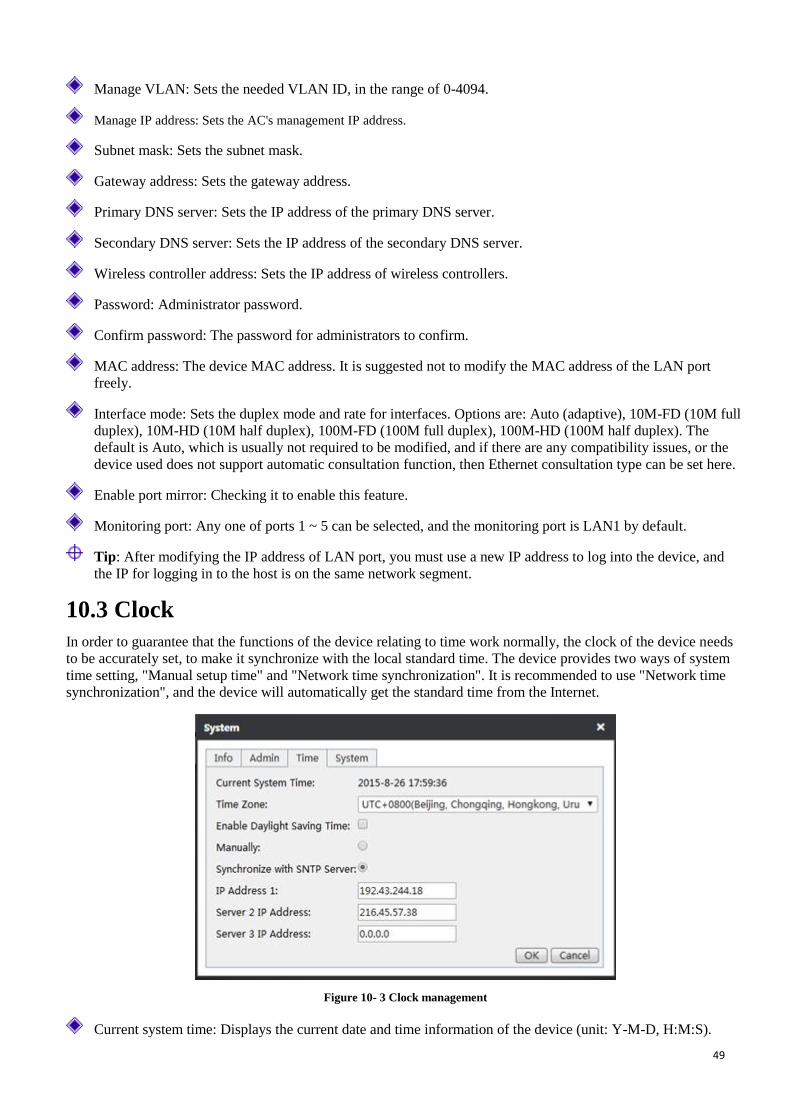
10.2 Management
Under this page, you can modify the IP address of WAC-1000 / WAC-1001, the address of wireless controllers,
and user names and passwords, etc., which is detailed in the following figure.
Figure 10- 2 Systems management
49
Manage VLAN: Sets the needed VLAN ID, in the range of 0-4094.
Manage IP address: Sets the AC's management IP address.
Subnet mask: Sets the subnet mask.
Gateway address: Sets the gateway address.
Primary DNS server: Sets the IP address of the primary DNS server.
Secondary DNS server: Sets the IP address of the secondary DNS server.
Wireless controller address: Sets the IP address of wireless controllers.
Password: Administrator password.
Confirm password: The password for administrators to confirm.
MAC address: The device MAC address. It is suggested not to modify the MAC address of the LAN port
freely.
Interface mode: Sets the duplex mode and rate for interfaces. Options are: Auto (adaptive), 10M-FD (10M full
duplex), 10M-HD (10M half duplex), 100M-FD (100M full duplex), 100M-HD (100M half duplex). The
default is Auto, which is usually not required to be modified, and if there are any compatibility issues, or the
device used does not support automatic consultation function, then Ethernet consultation type can be set here.
Enable port mirror: Checking it to enable this feature.
Monitoring port: Any one of ports 1 ~ 5 can be selected, and the monitoring port is LAN1 by default.
Tip: After modifying the IP address of LAN port, you must use a new IP address to log into the device, and
the IP for logging in to the host is on the same network segment.
10.3 Clock
In order to guarantee that the functions of the device relating to time work normally, the clock of the device needs
to be accurately set, to make it synchronize with the local standard time. The device provides two ways of system
time setting, "Manual setup time" and "Network time synchronization". It is recommended to use "Network time
synchronization", and the device will automatically get the standard time from the Internet.
Figure 10- 3 Clock management
Current system time: Displays the current date and time information of the device (unit: Y-M-D, H:M:S).

50
Time zone selection: Selects the international time zone in which the device resides. Only choosing a correct
time zone can the network time synchronization function work properly.
Manual time setting: Manually enters the current date and time (unit: Y-M-D, H:M:S).
Network time synchronization: After using the network time synchronization function to set up the right NTP
server, and when the device is connected to the Internet, it will automatically synchronize the time with the set
NTP server. The two NTP server addresses preset by the system by default are 111.43.244.18, 216.45.57.38,
which generally requires no change. If you need to know more about the NTP knowledge and the server, just
visit http://www.ntp.org.
Tip:It is recommended to set the device clock to synchronization with network time. Only when the system
time is properly configured can the configurations related to time, such as firewall work normally!
10.4 Systems In the System—>Page, you can back up the WAC-1000 / WAC-1001 configuration files to the local PC, import
the new configuration file to the system, restore the factory configuration and view the information of the currently
running version.
Figure 10- 4 System configuration
Back up configuration file: Click on the Save button in the above figure, to back up the WAC - 1000 / WAC -
1000 configuration file to the local PC, and the the format of the configuration file is .xml.
Import configuration file: Click on the Select files button in the above figure, and then import the
configuration file from the local PC. If you have checked the check box Restore factory configuration
before import, and then click the Import button, and the device will be recovered to the factory configuration
before importing the new configuration file.
Note: Please do not close the device power supply in the process of loading configuration, in order to
avoid unexpected errors.
Restore factory configuration: Click the Restore button in the above figure and restart the device, to restore
the factory configuration.
Tip:
① Recovery of device factory settings will delete all the custom configurations. It is strongly recommended that
before restoring the factory configuration, first back up its configuration files.
② The user name and password of the device's factory administrator are as follows: admin, and the default LAN
port IP address/subnet mask is: 192.168.1.252/255.255.255.0.

51
Steps for upgrading the WAC-1000 / WAC-1001 software:
① Download the latest version of software of the same model from the LevelOne official website. It is
recommended to back up the current configuration of the system before upgrade.
② Click on the Select file button under the software upgrade configuration in the above figure, and find the latest
version of software on the local computer.
③ After selecting the software, click on the Upgrade button, to upgrade the software on your device.
Tip:
① It is strongly recommended that upgrade is made when the device load is low (less users).
② Upgrading device software on a regular basis enables the device to get more functions or to have a better
working performance. The right software upgrade will not change the current device settings.
③ During the upgrade process, the device's power supply cannot be shut down, otherwise it will cause
unpredictable errors and even irreversible damages to the hardware.
④ The software will automatically restart to take effect after the completion of upgrade, without human
intervention.

52
Chapter 11 FAQ A - 1 Device is used as wireless client, why can a wireless connection not be established?
After confirming that the device is powered normally and connected normally, please check the following
configurations of the wireless devices in the network:
1. The "AP SSID" values set by the wireless client are consistent with the SSID of the associated wireless
device or not.
2. The "AP MAC" values set by the wireless client are consistent with the MAC address of the associated
wireless device or not.
3. The safe mode and key set by the wireless client are consistent with those of the associated wireless device
or not.
4. The associated device has already enabled the wireless feature, and has been the AP mode or not.
A - 2 How to restore the device to the factory settings?
Tip: The following method will delete all original configurations of the device, so please use it with care.
Case I: Know the administrator password
Under normal circumstances, you can directly enter the System management- > Configuration management
page, and then click restore to manually restart the device, and the device can be restored to its factory
configuration.
Case II: Forget the administrator password
If you forget the administrator password, you will not be able to enter the WEB interface, and now you can only
use the Reset button to restore the factory configuration. Method: In the process of charged operation, hold down
the Reset button for more than 5 seconds, then release the button, and the device will be returned to the factory
settings, and automatically restart.
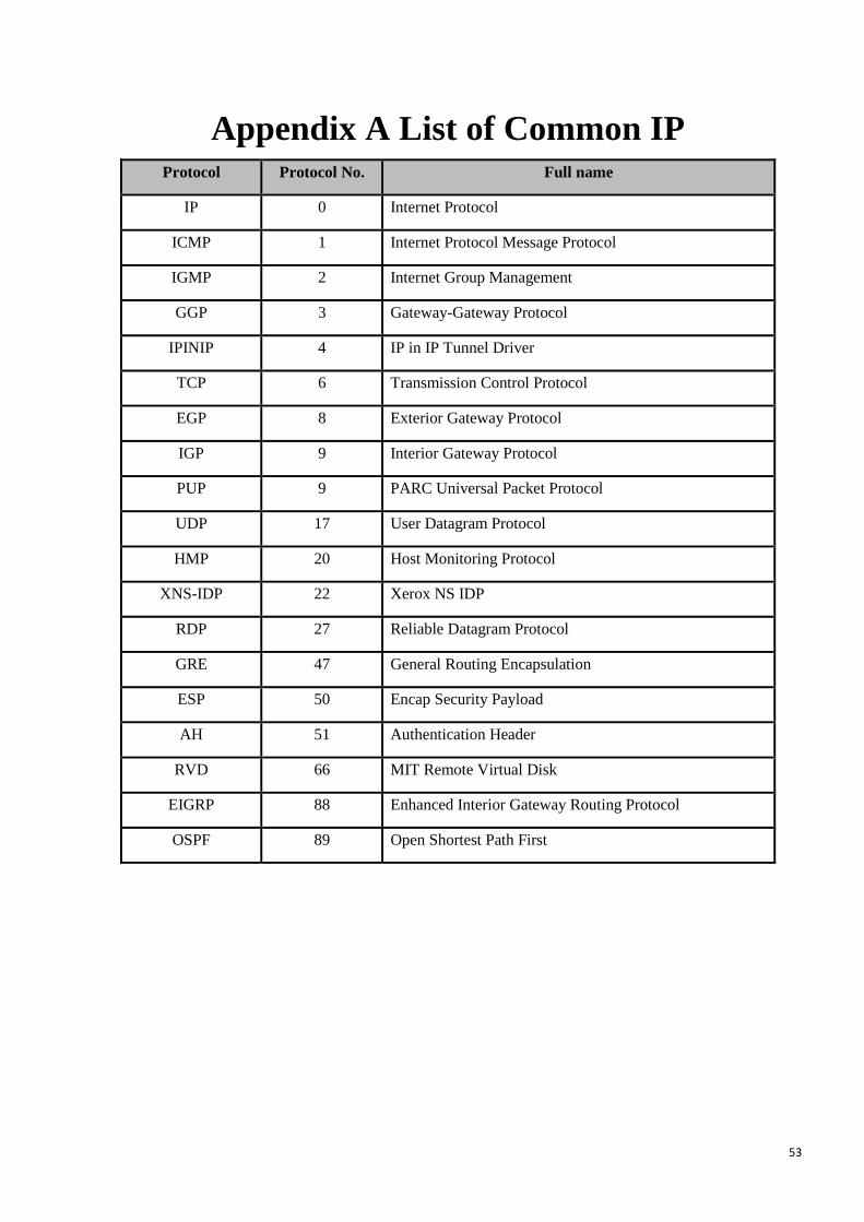
53
Appendix A List of Common IP Protocol Protocol No. Full name
IP 0 Internet Protocol
ICMP 1 Internet Protocol Message Protocol
IGMP 2 Internet Group Management
GGP 3 Gateway-Gateway Protocol
IPINIP 4 IP in IP Tunnel Driver
TCP 6 Transmission Control Protocol
EGP 8 Exterior Gateway Protocol
IGP 9 Interior Gateway Protocol
PUP 9 PARC Universal Packet Protocol
UDP 17 User Datagram Protocol
HMP 20 Host Monitoring Protocol
XNS-IDP 22 Xerox NS IDP
RDP 27 Reliable Datagram Protocol
GRE 47 General Routing Encapsulation
ESP 50 Encap Security Payload
AH 51 Authentication Header
RVD 66 MIT Remote Virtual Disk
EIGRP 88 Enhanced Interior Gateway Routing Protocol
OSPF 89 Open Shortest Path First
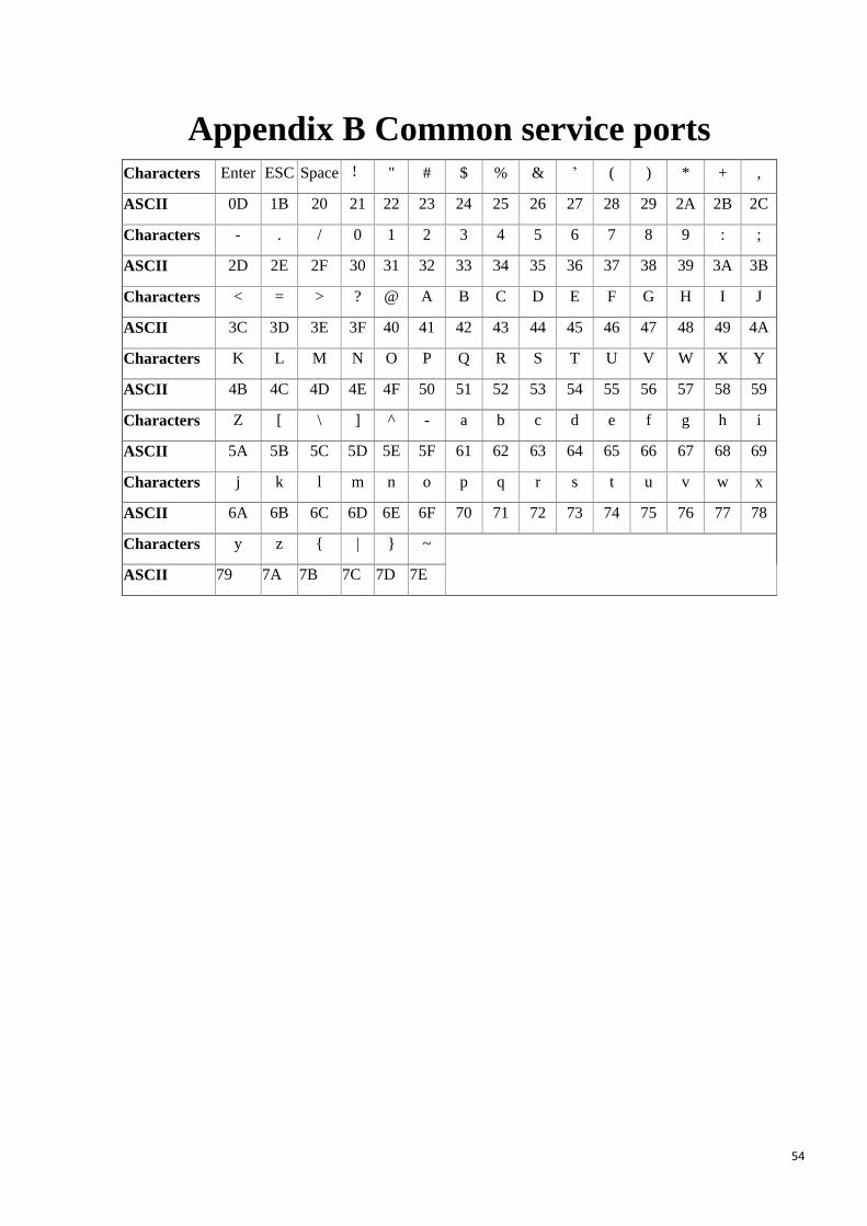
54
Appendix B Common service ports Characters Enter ESC Space ! " # $ % & ’ ( ) * + ,
ASCII 0D 1B 20 21 22 23 24 25 26 27 28 29 2A 2B 2C
Characters - . / 0 1 2 3 4 5 6 7 8 9 : ;
ASCII 2D 2E 2F 30 31 32 33 34 35 36 37 38 39 3A 3B
Characters < = > ? @ A B C D E F G H I J
ASCII 3C 3D 3E 3F 40 41 42 43 44 45 46 47 48 49 4A
Characters K L M N O P Q R S T U V W X Y
ASCII 4B 4C 4D 4E 4F 50 51 52 53 54 55 56 57 58 59
Characters Z [ \ ] ^ - a b c d e f g h i
ASCII 5A 5B 5C 5D 5E 5F 61 62 63 64 65 66 67 68 69
Characters j k l m n o p q r s t u v w x
ASCII 6A 6B 6C 6D 6E 6F 70 71 72 73 74 75 76 77 78
Characters y z { | } ~
ASCII 79 7A 7B 7C 7D 7E

55
Appendix C Figure index Table 0- 1 Factory configuration of interfaces ............................................................................ 2
Figure 2- 1 Front Panel ............................................................................................................ 4
Table 2-1 Description of LEDs ................................................................................................. 4
Table 2-2 Description of Ports .................................................................................................. 4
Figure 2- 2 Attaching Brackets to the Device 1 ........................................................................... 6
Figure 2- 3 Mounting the Device in a Rack 2 ............................................................................. 6
Figure 2-4 Connecting the Device to Network ............................................................................ 6
Figure 3-1 Web UI Login Window ........................................................................................... 8
Figure 3-2 Web UI Home Page ................................................................................................ 9
Figure 4- 1 Page of distribution map ....................................................................................... 10
Figure 4- 2 AP Summary ....................................................................................................... 11
Figure 4- 3 AP Details ........................................................................................................... 11
Figure 4- 4 Load detection ..................................................................................................... 12
Figure 4- 5 Interference detection ........................................................................................... 13
Figure 4- 6 AP Overlay Plot ................................................................................................... 13
Figure 4- 7 Coverage distance of map ..................................................................................... 14
Figure 4- 8 Import drawing interface ....................................................................................... 14
Figure 4- 9 Drawings import .................................................................................................. 15
Figure 5- 1 Statistical chart .................................................................................................... 16
Figure 6- 1 AC and AP centralized manager communicate on the second floor ............................. 18
Figure 6- 2 Roaming on the second floor ................................................................................. 19
Figure 6- 3 Device interface ................................................................................................... 19
Figure 6- 4 Batch settings ...................................................................................................... 20
Figure 6- 5 System information .............................................................................................. 21
Figure 6 - 6 Trend statistics .................................................................................................... 22
Figure 6- 7 Radio frequency information ................................................................................. 23

56
Figure 6- 8 Client ................................................................................................................. 24
Figure 6- 9 Radio frequency settings ....................................................................................... 25
Figure 6- 10 Setting of service area ......................................................................................... 26
Figure 6- 11 System settings .................................................................................................. 26
Figure 6- 12 Network settings ................................................................................................ 27
Figure6- 13 Software upgrade diagram .................................................................................... 27
Figure 7- 1 User online interface............................................................................................. 28
Figure 7- 2 Offline interface ................................................................................................... 28
Figure 7- 3 Blacklist interface ................................................................................................ 29
Figure 8- 1 Log information interface ...................................................................................... 30
Figure 8- 2 Log settings - Category ......................................................................................... 30
Figure 8- 3 Log settings - Monitoring ...................................................................................... 31
Figure 9- 1 Setting interface ................................................................................................... 32
Figure 9- 2 Wireless settings .................................................................................................. 33
Figure 9- 3 VLAN settings ..................................................................................................... 34
Figure 9- 4 WEP ................................................................................................................... 35
Figure 9- 5 WPA/WPA2 ........................................................................................................ 36
Figure 9- 6 WPA-PSK/WPA2-PSK ........................................................................................ 37
Figure 9- 7 No security mechanism ......................................................................................... 38
Figure 9- 8 Broadband restrictions .......................................................................................... 38
Figure 9- 9 RF template interface............................................................................................ 39
Figure 9- 10 Radio frequency template .................................................................................... 39
Figure 9- 11 Load balancing .................................................................................................. 41
Figure 9- 12 Load balancing .................................................................................................. 41
Figure 9- 13 Software management ......................................................................................... 41
Figure 9- 14 AP centralized management configuration instance ................................................ 43
Figure 9- 15 Service area configuration ................................................................................... 43
Figure 9- 16 Three-layer environment ..................................................................................... 45

57
Figure 9- 17 AC IP address configuration ................................................................................ 45
Figure 9- 18 AP management list ............................................................................................ 47
Figure 10- 1 System information ............................................................................................ 48
Figure 10- 2 Systems management .......................................................................................... 48
Figure 10- 3 Clock management ............................................................................................. 49
Figure 10- 4 System configuration .......................................................................................... 50
58
Appendix D LICENSE STATEMENT / GPL
CODE STATEMENT
This product resp. the here
(http://global.level1.com/downloads.php?action=init) for
downloading offered software includes software code developed
by third parties, including software code subject to the GNU
General Public License Version 2 (“GPLv2”) and GNU Lesser
General Public License 2.1 („LGPLv2.1“).
WRITTEN OFFER FOR GPL/LGPL
SOURCE CODE We will provide everyone upon request the applicable GPLv2 and
LGPLv2.1 source code files via CDROM or similar storage medium
for a nominal cost to cover shipping and media charges as allowed
under the GPLv2 and LGPLv2.1. This offer is valid for 3 years.
GPLv2 and LGPLv2 inquiries: Please direct all GPL and LGPL
inquiries to the following address:
Digital Data Communications GmbH
Zeche-Norm-Str. 25
44319 Dortmund
Deutschland

59
Phone: +49 231 9075 - 0
Fax: +49 231 9075 - 184
Email: [email protected]
Web: www.level1.com
NO WARRANTY This program is distributed in the hope that it will be useful, but
WITHOUT ANY WARRANTY; without even the implied warranty of
MERCHANTABILITY or FITNESS FOR A PARTICULAR
PURPOSE. See the GNU General Public License for more details.
IN NO EVENT UNLESS REQUIRED BY APPLICABLE LAW OR
AGREED TO IN WRITING WILL ANY COPYRIGHT HOLDER, OR
ANY OTHER PARTY WHO MAY MODIFY AND/OR
REDISTRIBUTE THE PROGRAM AS PERMITTED ABOVE, BE
LIABLE TO YOU FOR DAMAGES, INCLUDING ANY GENERAL,
SPECIAL, INCIDENTAL OR CONSEQUENTIAL DAMAGES
ARISING OUT OF THE USE OR INABILITY TO USE THE
PROGRAM (INCLUDING BUT NOT LIMITED TO LOSS OF DATA
OR DATA BEING RENDERED INACCURATE OR LOSSES
SUSTAINED BY YOU OR THIRD PARTIES OR A FAILURE OF
60
THE PROGRAM TO OPERATE WITH ANY OTHER PROGRAMS),
EVEN IF SUCH HOLDER OR OTHER PARTY HAS BEEN
ADVISED OF THE POSSIBILITY OF SUCH DAMAGES.
GNU GENERAL PUBLIC LICENSE Version 2, June 1991
Copyright (C) 1989, 1991 Free Software Foundation, Inc.
51 Franklin Street, Fifth Floor, Boston, MA 02110-1301, USA
Everyone is permitted to copy and distribute verbatim copies
of this license document, but changing it is not allowed.
Preamble The licenses for most software are designed to take away your
freedom to share and change it. By contrast, the GNU General
Public License is intended to guarantee your freedom to share and
change free software--to make sure the software is free for all its
users. This General Public License applies to most of the Free
Software Foundation's software and to any other program whose
authors commit to using it. (Some other Free Software Foundation
software is covered by the GNU Lesser General Public License
instead.) You can apply it to your programs, too.
When we speak of free software, we are referring to freedom, not
price. Our General Public Licenses are designed to make sure that
you have the freedom to distribute copies of free software (and

61
charge for this service if you wish), that you receive source code or
can get it if you want it, that you can change the software or use
pieces of it in new free programs; and that you know you can do
these things.
To protect your rights, we need to make restrictions that forbid
anyone to deny you these rights or to ask you to surrender the
rights. These restrictions translate to certain responsibilities for you
if you distribute copies of the software, or if you modify it.
For example, if you distribute copies of such a program, whether
gratis or for a fee, you must give the recipients all the rights that
you have. You must make sure that they, too, receive or can get
the source code. And you must show them these terms so they
know their rights.
We protect your rights with two steps: (1) copyright the software,
and (2) offer you this license which gives you legal permission to
copy, distribute and/or modify the software.
Also, for each author's protection and ours, we want to make
certain that everyone understands that there is no warranty for this
free software. If the software is modified by someone else and
passed on, we want its recipients to know that what they have is
not the original, so that any problems introduced by others will not
reflect on the original authors' reputations.
62
Finally, any free program is threatened constantly by software
patents. We wish to avoid the danger that redistributors of a free
program will individually obtain patent licenses, in effect making
the program proprietary. To prevent this, we have made it clear
that any patent must be licensed for everyone's free use or not
licensed at all.
The precise terms and conditions for copying, distribution and
modification follow.
TERMS AND CONDITIONS FOR
COPYING, DISTRIBUTION AND
MODIFICATION 0. This License applies to any program or other work which
contains a notice placed by the copyright holder saying it may be
distributed under the terms of this General Public License. The
"Program", below, refers to any such program or work, and a "work
based on the Program" means either the Program or any
derivative work under copyright law: that is to say, a work
containing the Program or a portion of it, either verbatim or with
modifications and/or translated into another language. (Hereinafter,
translation is included without limitation in the term "modification".)
Each licensee is addressed as "you".

63
Activities other than copying, distribution and modification are not
covered by this License; they are outside its scope. The act of
running the Program is not restricted, and the output from the
Program is covered only if its contents constitute a work based on
the Program (independent of having been made by running the
Program). Whether that is true depends on what the Program
does.
1. You may copy and distribute verbatim copies of the Program's
source code as you receive it, in any medium, provided that you
conspicuously and appropriately publish on each copy an
appropriate copyright notice and disclaimer of warranty; keep
intact all the notices that refer to this License and to the absence of
any warranty; and give any other recipients of the Program a copy
of this License along with the Program.
You may charge a fee for the physical act of transferring a copy,
and you may at your option offer warranty protection in exchange
for a fee.
2. You may modify your copy or copies of the Program or any
portion of it, thus forming a work based on the Program, and copy
and distribute such modifications or work under the terms of
Section 1 above, provided that you also meet all of these
conditions:

64
a) You must cause the modified files to carry prominent notices
stating that you changed the files and the date of any change.
b) You must cause any work that you distribute or publish, that in
whole or in part contains or is derived from the Program or any part
thereof, to be licensed as a whole at no charge to all third parties
under the terms of this License.
c) If the modified program normally reads commands interactively
when run, you must cause it, when started running for such
interactive use in the most ordinary way, to print or display an
announcement including an appropriate copyright notice and a
notice that there is no warranty (or else, saying that you provide a
warranty) and that users may redistribute the program under these
conditions, and telling the user how to view a copy of this License.
(Exception: if the Program itself is interactive but does not normally
print such an announcement, your work based on the Program is
not required to print an announcement.)
These requirements apply to the modified work as a whole. If
identifiable sections of that work are not derived from the Program,
and can be reasonably considered independent and separate

65
works in themselves, then this License, and its terms, do not apply
to those sections when you distribute them as separate works. But
when you distribute the same sections as part of a whole which is
a work based on the Program, the distribution of the whole must be
on the terms of this License, whose permissions for other
licensees extend to the entire whole, and thus to each and every
part regardless of who wrote it.
Thus, it is not the intent of this section to claim rights or contest
your rights to work written entirely by you; rather, the intent is to
exercise the right to control the distribution of derivative or
collective works based on the Program.
In addition, mere aggregation of another work not based on the
Program with the Program (or with a work based on the Program)
on a volume of a storage or distribution medium does not bring the
other work under the scope of this License.
3. You may copy and distribute the Program (or a work based on it,
under Section 2) in object code or executable form under the terms
of Sections 1 and 2 above provided that you also do one of the
following:
we use this doubled UL to get the sub-sections indented, while
making the bullets as unobvious as possible.

66
a) Accompany it with the complete corresponding
machine-readable source code, which must be distributed under
the terms of Sections 1 and 2 above on a medium customarily
used for software interchange; or,
b) Accompany it with a written offer, valid for at least three years,
to give any third party, for a charge no more than your cost of
physically performing source distribution, a complete
machine-readable copy of the corresponding source code, to be
distributed under the terms of Sections 1 and 2 above on a
medium customarily used for software interchange; or,
c) Accompany it with the information you received as to the offer to
distribute corresponding source code. (This alternative is allowed
only for noncommercial distribution and only if you received the
program in object code or executable form with such an offer, in
accord with Subsection b above.)
The source code for a work means the preferred form of the work
for making modifications to it. For an executable work, complete
source code means all the source code for all modules it contains,
plus any associated interface definition files, plus the scripts used
to control compilation and installation of the executable. However,
67
as a special exception, the source code distributed need not
include anything that is normally distributed (in either source or
binary form) with the major components (compiler, kernel, and so
on) of the operating system on which the executable runs, unless
that component itself accompanies the executable.
If distribution of executable or object code is made by offering
access to copy from a designated place, then offering equivalent
access to copy the source code from the same place counts as
distribution of the source code, even though third parties are not
compelled to copy the source along with the object code.
4. You may not copy, modify, sublicense, or distribute the Program
except as expressly provided under this License. Any attempt
otherwise to copy, modify, sublicense or distribute the Program is
void, and will automatically terminate your rights under this
License. However, parties who have received copies, or rights,
from you under this License will not have their licenses terminated
so long as such parties remain in full compliance.
5. You are not required to accept this License, since you have not
signed it. However, nothing else grants you permission to modify
or distribute the Program or its derivative works. These actions are
prohibited by law if you do not accept this License. Therefore, by
modifying or distributing the Program (or any work based on the

68
Program), you indicate your acceptance of this License to do so,
and all its terms and conditions for copying, distributing or
modifying the Program or works based on it.
6. Each time you redistribute the Program (or any work based on
the Program), the recipient automatically receives a license from
the original licensor to copy, distribute or modify the Program
subject to these terms and conditions. You may not impose any
further restrictions on the recipients' exercise of the rights granted
herein. You are not responsible for enforcing compliance by third
parties to this License.
7. If, as a consequence of a court judgment or allegation of patent
infringement or for any other reason (not limited to patent issues),
conditions are imposed on you (whether by court order, agreement
or otherwise) that contradict the conditions of this License, they do
not excuse you from the conditions of this License. If you cannot
distribute so as to satisfy simultaneously your obligations under
this License and any other pertinent obligations, then as a
consequence you may not distribute the Program at all. For
example, if a patent license would not permit royalty-free
redistribution of the Program by all those who receive copies
directly or indirectly through you, then the only way you could

69
satisfy both it and this License would be to refrain entirely from
distribution of the Program.
If any portion of this section is held invalid or unenforceable under
any particular circumstance, the balance of the section is intended
to apply and the section as a whole is intended to apply in other
circumstances.
It is not the purpose of this section to induce you to infringe any
patents or other property right claims or to contest validity of any
such claims; this section has the sole purpose of protecting the
integrity of the free software distribution system, which is
implemented by public license practices. Many people have made
generous contributions to the wide range of software distributed
through that system in reliance on consistent application of that
system; it is up to the author/donor to decide if he or she is willing
to distribute software through any other system and a licensee
cannot impose that choice.
This section is intended to make thoroughly clear what is believed
to be a consequence of the rest of this License.
8. If the distribution and/or use of the Program is restricted in
certain countries either by patents or by copyrighted interfaces, the
original copyright holder who places the Program under this
License may add an explicit geographical distribution limitation

70
excluding those countries, so that distribution is permitted only in
or among countries not thus excluded. In such case, this License
incorporates the limitation as if written in the body of this License.
9. The Free Software Foundation may publish revised and/or new
versions of the General Public License from time to time. Such
new versions will be similar in spirit to the present version, but may
differ in detail to address new problems or concerns.
Each version is given a distinguishing version number. If the
Program specifies a version number of this License which applies
to it and "any later version", you have the option of following the
terms and conditions either of that version or of any later version
published by the Free Software Foundation. If the Program does
not specify a version number of this License, you may choose any
version ever published by the Free Software Foundation.
10. If you wish to incorporate parts of the Program into other free
programs whose distribution conditions are different, write to the
author to ask for permission. For software which is copyrighted by
the Free Software Foundation, write to the Free Software
Foundation; we sometimes make exceptions for this. Our decision
will be guided by the two goals of preserving the free status of all
derivatives of our free software and of promoting the sharing and
reuse of software generally.
71
NO WARRANTY
11. BECAUSE THE PROGRAM IS LICENSED FREE OF
CHARGE, THERE IS NO WARRANTY FOR THE PROGRAM, TO
THE EXTENT PERMITTED BY APPLICABLE LAW. EXCEPT
WHEN OTHERWISE STATED IN WRITING THE COPYRIGHT
HOLDERS AND/OR OTHER PARTIES PROVIDE THE
PROGRAM "AS IS" WITHOUT WARRANTY OF ANY KIND,
EITHER EXPRESSED OR IMPLIED, INCLUDING, BUT NOT
LIMITED TO, THE IMPLIED WARRANTIES OF
MERCHANTABILITY AND FITNESS FOR A PARTICULAR
PURPOSE. THE ENTIRE RISK AS TO THE QUALITY AND
PERFORMANCE OF THE PROGRAM IS WITH YOU. SHOULD
THE PROGRAM PROVE DEFECTIVE, YOU ASSUME THE
COST OF ALL NECESSARY SERVICING, REPAIR OR
CORRECTION.
12. IN NO EVENT UNLESS REQUIRED BY APPLICABLE LAW
OR AGREED TO IN WRITING WILL ANY COPYRIGHT HOLDER,
OR ANY OTHER PARTY WHO MAY MODIFY AND/OR
REDISTRIBUTE THE PROGRAM AS PERMITTED ABOVE, BE
LIABLE TO YOU FOR DAMAGES, INCLUDING ANY GENERAL,
SPECIAL, INCIDENTAL OR CONSEQUENTIAL DAMAGES
ARISING OUT OF THE USE OR INABILITY TO USE THE
72
PROGRAM (INCLUDING BUT NOT LIMITED TO LOSS OF DATA
OR DATA BEING RENDERED INACCURATE OR LOSSES
SUSTAINED BY YOU OR THIRD PARTIES OR A FAILURE OF
THE PROGRAM TO OPERATE WITH ANY OTHER PROGRAMS),
EVEN IF SUCH HOLDER OR OTHER PARTY HAS BEEN
ADVISED OF THE POSSIBILITY OF SUCH DAMAGES.
END OF TERMS AND CONDITIONS
How to Apply These Terms to Your
New Programs If you develop a new program, and you want it to be of the greatest
possible use to the public, the best way to achieve this is to make it
free software which everyone can redistribute and change under
these terms.
To do so, attach the following notices to the program. It is safest to
attach them to the start of each source file to most effectively
convey the exclusion of warranty; and each file should have at
least the "copyright" line and a pointer to where the full notice is
found.
one line to give the program's name and an idea of what it does.
Copyright (C) yyyy name of author
This program is free software; you can redistribute it and/or
modify it under the terms of the GNU General Public License
as published by the Free Software Foundation; either version 2
of the License, or (at your option) any later version.
73
This program is distributed in the hope that it will be useful,
but WITHOUT ANY WARRANTY; without even the implied warranty of
MERCHANTABILITY or FITNESS FOR A PARTICULAR PURPOSE. See the
GNU General Public License for more details.
You should have received a copy of the GNU General Public License
along with this program; if not, write to the Free Software
Foundation, Inc., 51 Franklin Street, Fifth Floor, Boston, MA
02110-1301, USA.
Also add information on how to contact you by electronic and
paper mail.
If the program is interactive, make it output a short notice like this
when it starts in an interactive mode:
Gnomovision version 69, Copyright (C) year name of author
Gnomovision comes with ABSOLUTELY NO WARRANTY; for details
type `show w'. This is free software, and you are welcome
to redistribute it under certain conditions; type `show c'
for details.
The hypothetical commands `show w' and `show c' should show
the appropriate parts of the General Public License. Of course, the
commands you use may be called something other than `show w'
and `show c'; they could even be mouse-clicks or menu
items--whatever suits your program.
You should also get your employer (if you work as a programmer)
or your school, if any, to sign a "copyright disclaimer" for the
program, if necessary. Here is a sample; alter the names:
Yoyodyne, Inc., hereby disclaims all copyright
interest in the program `Gnomovision'
(which makes passes at compilers) written
by James Hacker.
signature of Ty Coon, 1 April 1989

74
Ty Coon, President of Vice
This General Public License does not permit incorporating your
program into proprietary programs. If your program is a subroutine
library, you may consider it more useful to permit linking
proprietary applications with the library. If this is what you want to
do, use the GNU Lesser General Public License instead of this
License.
Notification of Compliance
Europe - EU Declaration of Conformity
For complete DoC please visit
http://global.level1.com/downloads.php?action=init
GPL License Agreement
GPL may be included in this product, to view the GPL license agreement goes to
http://download.level1.com/level1/gpl/GPL.pdf
For GNU General Public License (GPL) related information, please visit
http://global.level1.com/downloads.php?action=init

75

![WAC 182 - 12 CHAPTER - lawfilesext.leg.wa.govlawfilesext.leg.wa.gov/law/WACArchive/2014/WAC 182 - 12 CHAPTE… · (10/28/13) [Ch. 182-12 WAC p. 1] Chapter 182-12 Chapter 182-12 WAC](https://static.fdocuments.in/doc/165x107/5f937086d75d77697316c603/wac-182-12-chapter-182-12-chapte-102813-ch-182-12-wac-p-1-chapter.jpg)