Levelflex FMP51, FMP52, FMP54 - pzip.rupzip.ru/downloads/endress+hauser/KA01079FEN_1312.pdf ·...
52
Brief Operating Instructions Levelflex FMP51, FMP52, FMP54 Guided Level-Radar These Instructions are Brief Operating Instructions; they do not replace the Operating Instructions included in the scope of supply. For detailed information, refer to the Operating Instructions and other documentation on the CD-ROM provided or visit ƀwww.endress.com/ deviceviewerƀ. KA01079F/00/EN/13.12 71206446
-
Upload
vuongnguyet -
Category
Documents
-
view
237 -
download
0
Transcript of Levelflex FMP51, FMP52, FMP54 - pzip.rupzip.ru/downloads/endress+hauser/KA01079FEN_1312.pdf ·...
Brief Operating Instructions
Levelflex FMP51, FMP52, FMP54Guided Level-Radar
These Instructions are Brief Operating Instructions; they do not replace theOperating Instructions included in the scope of supply.
For detailed information, refer to the Operating Instructions and otherdocumentation on the CD-ROM provided or visit www.endress.com/deviceviewer .
KA01079F/00/EN/13.1271206446

Table of contents Levelflex FMP51, FMP52, FMP54
2 Endress+Hauser
Table of contents
1 Important document information . . . . . . . . . . . . . . . . . . . . . . . . . . . . . . . 31.1 Document conventions . . . . . . . . . . . . . . . . . . . . . . . . . . . . . . . . . . . . . . . . . . . 3
2 Basic safety instructions . . . . . . . . . . . . . . . . . . . . . . . . . . . . . . . . . . . . . . 42.1 Requirements concerning the staff . . . . . . . . . . . . . . . . . . . . . . . . . . . . . . . . . . . . . . 42.2 Designated use . . . . . . . . . . . . . . . . . . . . . . . . . . . . . . . . . . . . . . . . . . . . . . . 42.3 Workplace safety . . . . . . . . . . . . . . . . . . . . . . . . . . . . . . . . . . . . . . . . . . . . . . 52.4 Operational safety . . . . . . . . . . . . . . . . . . . . . . . . . . . . . . . . . . . . . . . . . . . . . . 52.5 Product safety . . . . . . . . . . . . . . . . . . . . . . . . . . . . . . . . . . . . . . . . . . . . . . . . 5
3 Product description . . . . . . . . . . . . . . . . . . . . . . . . . . . . . . . . . . . . . . . . . 63.1 Compact device Levelflex . . . . . . . . . . . . . . . . . . . . . . . . . . . . . . . . . . . . . . . . . . 63.2 Electronics housing . . . . . . . . . . . . . . . . . . . . . . . . . . . . . . . . . . . . . . . . . . . . . 7
4 Incoming acceptance and product identification . . . . . . . . . . . . . . . . . . . . . 84.1 Incoming acceptance . . . . . . . . . . . . . . . . . . . . . . . . . . . . . . . . . . . . . . . . . . . . 84.2 Product identification . . . . . . . . . . . . . . . . . . . . . . . . . . . . . . . . . . . . . . . . . . . . 9
5 Storage, Transport . . . . . . . . . . . . . . . . . . . . . . . . . . . . . . . . . . . . . . . . 105.1 Storage conditions . . . . . . . . . . . . . . . . . . . . . . . . . . . . . . . . . . . . . . . . . . . . . 105.2 Transport product to the measuring point . . . . . . . . . . . . . . . . . . . . . . . . . . . . . . . . . . 10
6 Mounting . . . . . . . . . . . . . . . . . . . . . . . . . . . . . . . . . . . . . . . . . . . . . . . 116.1 Suitable mounting position . . . . . . . . . . . . . . . . . . . . . . . . . . . . . . . . . . . . . . . . . 116.2 Notes on the process connection . . . . . . . . . . . . . . . . . . . . . . . . . . . . . . . . . . . . . . 126.3 Securing the probe . . . . . . . . . . . . . . . . . . . . . . . . . . . . . . . . . . . . . . . . . . . . . 176.4 Special mounting conditions . . . . . . . . . . . . . . . . . . . . . . . . . . . . . . . . . . . . . . . . 206.5 Mounting the device . . . . . . . . . . . . . . . . . . . . . . . . . . . . . . . . . . . . . . . . . . . . 246.6 Post-installation check . . . . . . . . . . . . . . . . . . . . . . . . . . . . . . . . . . . . . . . . . . . 29
7 Electrical connection . . . . . . . . . . . . . . . . . . . . . . . . . . . . . . . . . . . . . . . 307.1 Connection options . . . . . . . . . . . . . . . . . . . . . . . . . . . . . . . . . . . . . . . . . . . . 307.2 Connection options . . . . . . . . . . . . . . . . . . . . . . . . . . . . . . . . . . . . . . . . . . . . 327.3 Connection data . . . . . . . . . . . . . . . . . . . . . . . . . . . . . . . . . . . . . . . . . . . . . . 337.4 Connecting the measuring device . . . . . . . . . . . . . . . . . . . . . . . . . . . . . . . . . . . . . . 347.5 Post-connection check . . . . . . . . . . . . . . . . . . . . . . . . . . . . . . . . . . . . . . . . . . . 37
8 Integration into a PROFIBUS network . . . . . . . . . . . . . . . . . . . . . . . . . . . 378.1 Overview of the device database files (GSD) . . . . . . . . . . . . . . . . . . . . . . . . . . . . . . . . . 378.2 Set device address . . . . . . . . . . . . . . . . . . . . . . . . . . . . . . . . . . . . . . . . . . . . . 38
9 Commissioning via operating menu (On-site display, FieldCare) . . . . . . . . . 409.1 Display and operating module . . . . . . . . . . . . . . . . . . . . . . . . . . . . . . . . . . . . . . . 409.2 Operating concept . . . . . . . . . . . . . . . . . . . . . . . . . . . . . . . . . . . . . . . . . . . . . 429.3 Adjust the display contrast . . . . . . . . . . . . . . . . . . . . . . . . . . . . . . . . . . . . . . . . . 449.4 Unlock the device . . . . . . . . . . . . . . . . . . . . . . . . . . . . . . . . . . . . . . . . . . . . . 449.5 Set the operating language . . . . . . . . . . . . . . . . . . . . . . . . . . . . . . . . . . . . . . . . . 469.6 Configuration of a level measurement . . . . . . . . . . . . . . . . . . . . . . . . . . . . . . . . . . . . 479.7 Configuration of an interface measurement . . . . . . . . . . . . . . . . . . . . . . . . . . . . . . . . . 489.8 User-specific applications (operation) . . . . . . . . . . . . . . . . . . . . . . . . . . . . . . . . . . . . 49

Levelflex FMP51, FMP52, FMP54 Important document information
Endress+Hauser 3
1 Important document information
1.1 Document conventions
1.1.1 Safety symbolsin preparation
1.1.2 Electrical symbols
Symbol Meaning
A0011197
Direct currentA terminal to which DC voltage is applied or through which direct current flows.
A0011198
Alternating currentA terminal to which alternating voltage (sine-wave) is applied or through which alternating currentflows.
) A0011200
Ground connectionA grounded terminal which, as far as the operator is concerned, is grounded via a grounding system.
* A0011199
Protective ground connectionA terminal which must be connected to ground prior to establishing any other connections.
A0011201
Equipotential connectionA connection that has to be connected to the plant grounding system: This may be a potentialequalization line or a star grounding system depending on national or company codes of practice.
1.1.3 Tool symbols
A0011219 A0011220 A0013442 A0011221 A0011222
Phillips headscrewdriver
Flat bladescrewdriver
Torx screwdriver Allen key Hexagon wrench
1.1.4 Symbols for certain types of informationin preparation
1.1.5 Symbols in graphicsin preparation

Basic safety instructions Levelflex FMP51, FMP52, FMP54
4 Endress+Hauser
2 Basic safety instructions
2.1 Requirements concerning the staffThe staff must fulfill the following requirements for their tasks:► Trained staff: Must have a qualification which corresponds to their function and tasks.► Authorized by the plant operator.► Familiar with the national regulations.► Before starting their work: Must have read and understood all instructions in the operating
manual and supplementary documentation as well as the certificate (depending on theapplication).
► Must comply with all instructions and the regulatory framework.
2.2 Designated useApplication and measured materialsThe measuring device described in these Operating Instructions is intended only for level andinterface measurement of liquids. Depending on the version ordered the device can alsomeasure potentially explosive, flammable, poisonous and oxidizing materials.
Observing the limit values specified in the Technical data and listed in the OperatingInstructions and supplementary documentation, the measuring device may be used for thefollowing measurements only:► Measured process variable: Level and/or interface► Calculated process variable: Volume oder mass in arbitrarily shaped vessels (calculated
from the level by the linearization functionality)
To ensure that the measuring device remains in proper condition for the operation time:► Use the measuring device only for measured materials against which the process-wetted
materials are adequately resistant.► Observe the limit values in Technical data .
Incorrect useThe manufacturer is not liable for damage caused by improper or non-designated use.
Verification for borderline cases:► For special measured materials and cleaning agents, Endress+Hauser is glad to provide
assistance in verifying the corrosion resistance of wetted materials, but does not accept anywarranty or liability.
Residual riskThe electronics housing and its built-in components such as display module, main electronicsmodule and I/O electronics module may heat to 80 °C (176 °F) during operation throughheat transfer from the process as well as power dissipation within the electronics. Duringoperation the sensor may assume a temperature near the temperature of the measuredmaterial.
Danger of burns due to heated surfaces► For high process temperatures: Install protection against contact in order to prevent burns.
Levelflex FMP51, FMP52, FMP54 Basic safety instructions
Endress+Hauser 5
2.3 Workplace safetyFor work on and with the device:► Wear the required personal protective equipment according to federal/national regulations.
2.4 Operational safetyRisk of injury► Operate the device in proper technical condition and fail-safe condition only.► The operator is responsible for interference-free operation of the device.
Conversions to the device
Unauthorized modifications to the device are not permitted and can lead to unforeseeabledangers► If, despite this, modifications are required, consult with Endress+Hauser.
Repair
To ensure continued operational safety and reliability,► Carry out repairs on the device only if they are expressly permitted.► Observe federal/national regulations pertaining to repair of an electrical device.► Use original spare parts and accessories from Endress+Hauser only.
Hazardous area
To eliminate a danger for persons or for the facility when the device is used in the hazardousarea (e.g. explosion protection, pressure vessel safety):► Based on the nameplate, check whether the ordered device is permitted for the intended
use in the hazardous area.► Observe the specifications in the separate supplementary documentation that is an integral
part of these Instructions.
2.5 Product safetyThis measuring device is designed in accordance with good engineering practice to meet state-of-the- art safety requirements, has been tested, and left the factory in a condition in whichthey are safe to operate.
It fulfills general safety requirements and legal requirements. It also conforms to the ECdirectives listed in the device-specific EC declaration of conformity. Endress+Hauser confirmsthis fact by applying the CE mark.
Product description Levelflex FMP51, FMP52, FMP54
6 Endress+Hauser
3 Product description
3.1 Compact device Levelflex
1
2
53
4
6
A0012399
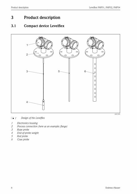
å 1 Design of the Levelflex
1 Electronics housing2 Process connection (here as an example: flange)3 Rope probe4 End-of-probe weight5 Rod probe6 Coax probe

Levelflex FMP51, FMP52, FMP54 Product description
Endress+Hauser 7
3.2 Electronics housing
Esc
–
+
E
1 2 3
4
5
6
9
7
8
A0012422
å 2 Design of the electronics housing
1 Electronics compartment cover2 Display module3 Main electronics module4 Cable glands (1 or 2, depending on instrument version)5 Nameplate6 I/O electronics module7 Terminals (pluggable spring terminals)8 Connection compartment cover9 Grounding terminal

Incoming acceptance and product identification Levelflex FMP51, FMP52, FMP54
8 Endress+Hauser
4 Incoming acceptance and product identification
4.1 Incoming acceptance
A0013696
DELIVERY NOTE
1 = 2
A0016870
A0013921
A0013696 A0013922

Levelflex FMP51, FMP52, FMP54 Incoming acceptance and product identification
Endress+Hauser 9
A0013696
DELIVERY NOTE
Made in Germany, 79689 Maulburg
A0014038
A0013696
A0014037
If one of the conditions does not comply, contact your Endress+Hauser distributor.
4.2 Product identificationThe following options are available for identification of the measuring device:• Nameplate specifications• Order code with breakdown of the device features on the delivery note• Enter serial numbers from nameplates in W@M Device Viewer
( www.endress.com/deviceviewer ): All information about the measuring device isdisplayed.
For an overview of the scope of the Technical Documentation provided, refer to the following:enter serial numbers from nameplates in W@M Device Viewer( www.endress.com/deviceviewer )
Storage, Transport Levelflex FMP51, FMP52, FMP54
10 Endress+Hauser
Order code:
Ext. ord. cd.:
Ser. no.:
1
2
3
A0014103
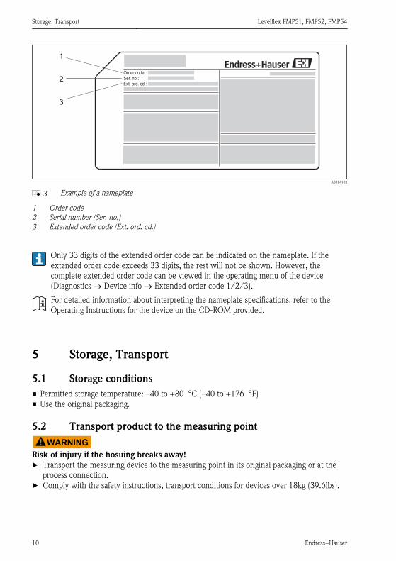
å 3 Example of a nameplate
1 Order code2 Serial number (Ser. no.)3 Extended order code (Ext. ord. cd.)
Only 33 digits of the extended order code can be indicated on the nameplate. If theextended order code exceeds 33 digits, the rest will not be shown. However, thecomplete extended order code can be viewed in the operating menu of the device(Diagnostics ® Device info ® Extended order code 1/2/3).
For detailed information about interpreting the nameplate specifications, refer to theOperating Instructions for the device on the CD-ROM provided.
5 Storage, Transport
5.1 Storage conditions• Permitted storage temperature: –40 to +80 °C (–40 to +176 °F)• Use the original packaging.
5.2 Transport product to the measuring pointWARNING
Risk of injury if the hosuing breaks away► Transport the measuring device to the measuring point in its original packaging or at the
process connection.► Comply with the safety instructions, transport conditions for devices over 18kg (39.6lbs).
Levelflex FMP51, FMP52, FMP54 Mounting
Endress+Hauser 11
A0013920
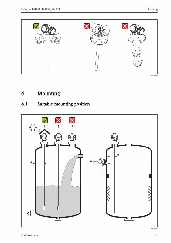
6 Mounting
6.1 Suitable mounting position
A
C
1 2 3
4
B
A0012606

Mounting Levelflex FMP51, FMP52, FMP54
12 Endress+Hauser
6.1.1 Mounting distances
• Distance (A) between wall and rod or rope probe:– for smooth metallic walls: > 50 mm (2 )– for plastic walls: > 300 mm (12 ) mm to metallic parts outside the vessel– for concrete walls: > 500 mm (20 ) , otherwise the available measuring range may be
reduced.• Distance (B) between rod or rope probe and internal fittings in the vessel: > 300 mm (12 )• Distance (C) from end of probe to bottom of the vessel:
– Rope probe: > 150 mm (6 in)– Rod probe: > 10 mm (0.4 in)– Coax probe: > 10 mm (0.4 in)
For coax probes the distance to the wall and to internal fittings is arbitrary.
6.1.2 Additional conditions
• When mounting in the open, a weather protection cover (1) may be installed to protect thedevice against extreme weather conditions.
• In metallic vessels: Preferably do not mount the probe in the center of the vessel (2), as thiswould lead to increased interference echoes.If a central mounting position can not be avoided, it is crucial to perform an interferenceecho suppresion(mapping) after the commissioning of the device.
• Do not mount the probe in the filling curtain (3).• Avoid buckling the rope probe during installation or operation (e.g. through product
movement against silo wall) by selecting a suitable mounting location.
With suspended rope probes (probe end not fixed at the bottom) the distance betweenthe probe rope and internal fittings in the tank must not fall below 300 mm (12 ) duringthe entire process. A sporadic contact between the probe weight and the cone of thevessel, however, does not influence the measurement as long as the dielectric constantof the medium is at least DC = 1.8.
When mounting the electronics housing into a recess (e.g. in a concrete ceiling), observea minimum distance of 100 mm (4 inch) between the cover of the terminalcompartment / electronics compartment and the wall. Otherwise the connectioncompartment / electronics compartment is not accessible after installation.
6.2 Notes on the process connectionProbes are mounted to the process connection with threaded connections or flanges. If duringthis installation there is the danger that the probe end moves so much that it touches the tankfloor or cone at times, the probe must, if necessary, be shortened and fixed down(® ä 17).

Levelflex FMP51, FMP52, FMP54 Mounting
Endress+Hauser 13
6.2.1 Threaded connection
A0015121
å 4 Mounting with threaded connection; flush with the container ceiling
SealThe thread as well as the type of seal comply to DIN 3852 Part 1, screwed plug form A.
They can be sealed with the following types of sealing rings:
• Thread G3/4 : According to DIN 7603 with the dimensions 27 x 32 mm• Thread G1-1/2 : According to DIN 7603 with the dimensions 48 x 55 mm
Please use a sealing ring according to this standard in the form A, C or D and of a material thatis resistant to the application.
For the length of the screwed plug refer to the dimensional drawing:• FMP51:• FMP54:
6.2.2 Nozzle mounting with flange
£150 (
6)
H
mm (in)ø 150 (6)£
A0015122

Mounting Levelflex FMP51, FMP52, FMP54
14 Endress+Hauser
For FMP52: Use spring washers in order to compensate a possible creep deformation ofthe PTFE cladding between the tank and the device flange; see figure below.
Alternative: Retighten the flange bolts periodically, depending on process temperatureand pressure. Recommended torque: 60 to 100 Nm (44.3 to 73.7 lbf ft).
mm (in)
1
450 (
18)
≤
A0016358
1 Spring wahsers ensure sufficient preload between the tank and the flange of the FMP52.
Hight and diameter of the nozzle
• Permissible nozzle diameter: £ 150 mm (6 in).For larger diameters the near range measuring capability may be reduced.For nozzles ³ DN300: (® ä 15).
• Permissible nozzle height 1): £ 150 mm (6 in).For a larger height the near range measuring capability may be reduced.Larger nozzle heights may be possible in special cases (see sections Center rod for FMP51and FMP52 and Rod extension/centering HMP40 for FMP54 ).
With thermally insulated vessels the nozzle should also be insulated in order to preventcondensate formation.
Center rod for FMP51 and FMP52For rope probes it may be necessary to use a version with center rod in order to prevent theprobe rod from coming into contact with the nozzle wall. Probes with center rod are availablefor FMP51 and FMP52.
Probe Max. nozzle height (= length of the center rod) Option to be selected in feature 060 ( Probe )
FMP51 150 mm LA
6 inch LB
300 mm MB
1) Larger nozzle heights on request
Levelflex FMP51, FMP52, FMP54 Mounting
Endress+Hauser 15
Probe Max. nozzle height (= length of the center rod) Option to be selected in feature 060 ( Probe )
12 inch MD
FMP52 150 mm OA
6 inch OC
300 mm OB
12 inch OD
Rod extension/centering HMP40 for FMP54For FMP54 with rope probes the rod extension/centering HMP 40 is available as an accessory(Verweisziel existiert nicht, aber @y.link.required='true'). It has to be used if otherwise theprobe rope comes into contact with the lower edge of the nozzle.
This accessory consists of the extension rod corresponding to the nozzle height, onwhich a centering disk is also mounted if the nozzles are narrow or when working inbulk solids. This component is delivered separately from the device. Please order theprobe length correspondingly shorter.
Centering disks with small diameters (DN40 and DN50) may only be used if there is nosignificant build-up in the nozzle above the disk. The nozzle must not become cloggedby the product.
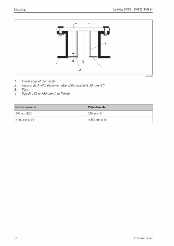
Installation in nozzles ³ DN300If installation in ≥ 300mm/12 nozzles is unavoidable, installation must be carried out inaccordance with the sketch on the right.
Mounting Levelflex FMP51, FMP52, FMP54
16 Endress+Hauser
1
2
3
4
A0014199
1 Lower edge of the nozzle2 Approx. flush with the lower edge of the nozzle (± 50 mm/2 )3 Plate4 Pipe Æ 150 to 180 mm (6 to 7 inch)
Nozzle diameter Plate diameter
300 mm (12 ) 280 mm (11 )
³ 400 mm (16 ) ³ 350 mm (14 )

Levelflex FMP51, FMP52, FMP54 Mounting
Endress+Hauser 17
6.3 Securing the probe
6.3.1 Securing rope probes
1
A
C
B
2
A0012609
A Sag of the rope: ³ 1 cm per 1m of the probe length (0.12 inch per 1 ft of the probe length)B Reliably grounded end of probeC Reliably isolated end of probe1: Mounting and contact with a bolt2 Mounting kit isolated
• The end of the probe needs to be secured under the following conditions:if otherwise the probe sporadically comes into contact with the wall of the vessel, the outletcone, internal fittings or other parts of the installation.
• The end of probe can be secured at its internal threadrope 4 mm (1/6 ), 316: M 14
• The fixing must be either reliably grounded or reliably insulated. If it is not possible tomount the probe weight with a reliably insulated connection, it can be secured using anisolated eyelet, which is available as an accessory .
• In order to prevent an extremely high tensile load (e.g. due to thermal expansion) and therisk of rope crack, the rope has to be slack. Make the rope longer than the requiredmeasuring range such that there is a sag in the middle of the rope that is ≥ 1cm/(1 m ropelength) [0.12 inch/(1 ft rope length)]. Tensile load limit of rope probes: (Verweiszielexistiert nicht, aber @y.link.required='true')
6.3.2 Securing rod probes
• For Ex-approvals: For probe lengths ³ 3 m (10 ft) a support is required.• In general, rod probes must be supported if there is a horizontal flow (e.g. from an agitator)
or in the case of strong vibrations.• Rod probes may only be supported at the end of the probe.

Mounting Levelflex FMP51, FMP52, FMP54
18 Endress+Hauser
mm (in)
ø a
ø b
»5
0 (
1.9
7)
1
2
3
»50 (
1.9
7)
4
5
6
ø<25 (1.0)
3 (0.12)»
A0012607
1 Probe rod, uncoated2 Sleeve bored tight to ensure electrical contact between the rod and sleeve3 Short metal pipe, e.g. welded in place4 Probe rod, coated5 Plastic sleeve, e.g. PTFE, PEEK or PPS6 Short metal pipe, e.g. welded in place
Æ probe Æ a [mm (inch)] Æ b [mm (inch)]
8 mm (1/3 ) < 14 (0.55) 8.5 (0.34)
12 mm (1/2 ) < 20 (0.78) 12.5 (0.52)
16 mm (0.63in) < 26 (1.02) 16.5 (0.65)

Levelflex FMP51, FMP52, FMP54 Mounting
Endress+Hauser 19
NOTICEPoor grounding of the end of probe may cause measuring errors.► Apply a narrow sleeve which has good electrical contact to the probe.
NOTICEWelding may damage the main electronics module.► Before welding: Ground the probe and dismount electronics.
6.3.3 Securing coax probes
For Ex-approvals: For probe lengths ³ 3 m (10 ft) a support is required.
A0012608
Coax probes can be supported at any point of the outer tube.

Mounting Levelflex FMP51, FMP52, FMP54
20 Endress+Hauser
6.4 Special mounting conditions
6.4.1 Bypasses and stilling wells
³100
(4)
³
³
³
100
(4)
Ø d
Ø D
Ød
25 Nm ± 5 Nm
25 Nm ± 5 Nmmm (in)
1 2
3.1
3.2
3
A0012615
1 Mounting in a stilling well2 Mounting in a bypass3 Center washer3.1 Metallic center washer (316L) for level measurement3.2 Non-metallic center washer (PEEK, PFA) for interface measurement
For information on bypass solutions from Endress+Hauser please contact your Endress+Hauser sales representative.
Feature 610 - Accessory mounted
Application Option Type of probe
Center washer Pipe
Æ d [mm (in)] Material Æ D [mm(in)]
Level measurement OA Rod probe 75 (2,95) 316L DN80/3to
DN100/4
OB Rod probe 45 (1,77) 316L DN50/2to
DN65/2½
OC Rope probe 75 (2,95) 316L DN80/3to
DN100/4

Levelflex FMP51, FMP52, FMP54 Mounting
Endress+Hauser 21
Feature 610 - Accessory mounted
Application Option Type of probe
Center washer Pipe
Æ d [mm (in)] Material Æ D [mm(in)]
Interface measurement OD Rod probe 48...95(1,89...3,74)
PEEK ³ 50 mm(2 )
OE Rope probe 37 (1,46) PFA ³ 40 mm(1.57 )
• Pipe diameter: > 40 mm (1.6 ) for rod probes• Rod probe installation can take place up to a diameter size of 100 mm. In the event of larger
diameters, a coax probe is recommended.• Side disposals, holes or slits and welded joints that protrude up to approx. 5 mm (0.2 )
inwards do not influence the measurement.• The pipe may not exhibit any steps in diameter.• The probe must be 100 mm longer than the lower disposal.• Within the measuring range, the probe must not get into contact with the pipe wall. If
necessary, use a center washer (see feature 610 of the product structure).• If the center washer is mounted at the end of the probe, it enables a reliable recognition of
the end-of-probe signal (see feature 610 of the product structure).Note: For interface measurements only use the nonmetallic center washers made of PEEKor PFA (feature 610, options OD or OE) .
• Coax probes can always be applied if there is enough mounting space.
For bypasses with condensate formation (water) and a medium with low dielectricconstant (e.g. hydrocarbons):
In the course of time the bypass is filled with condensate up to the lower disposal and forlow levels the the level echo is superimposed by the condensate echo. Thus in this rangethe condensate level is measured instead of the correct level. Only higher levels aremeasured correctly. To prevent this, position the lower disposal 100 mm (4 in) belowthe lowest level to be measured and apply a metallic centering disk at the height of thelower edge of the lower disposal.
With heat insulated tanks the bypass should also be insulated in order to preventcondensate formation.
For rope probes with a length exceeding 2 m (6.7 ft) an additional weight or a springshould be mounted in addition to the center a washer (option OC) in order to tightenthe rope. The mass of the center wahser is 155 g (5.5 oz).

Mounting Levelflex FMP51, FMP52, FMP54
22 Endress+Hauser
6.4.2 Non-metallic vessels
1
2
A0012527
1 Non-metallic vessel2 Metal sheet or metal flange
To measure, Levelflex with a rod probe needs a metallic surface at the process connection.Therefore:
• Select an instrument version with metal flange (minimum size DN50/2 ).• Or: mount a metal sheet with a diameter of at least 200 mm (8 ) to the probe at the process
connection. Its orientation must be perpendicular to the probe.
No additional measures are required for coax probes.

Levelflex FMP51, FMP52, FMP54 Mounting
Endress+Hauser 23
6.4.3 Plastic or glass tanks: Mounting the probe externally at the wall
1
2
a
3
A0014150
1 Plastic or glass tank2 Metall sheet with threaded sleeve3 No free space between tank wall and probe
Requirements• The dielectric constant of the medium must be at least DC > 7.• The tank wall must be non-conductvie.• Maximum wall thickness (a):
– Plastic: < 15 mm (0.6 )– Glass: < 10 mm (0.4 )
• There may be no metallic reinforcements fixed to the tank.
Mounting conditions:• The probe must be mounted directly to the tank wall (no open space)• A plastic half pipe with a diameter of approx. 200 mm (8 ), or some other protective unit,
must be affixed externally to the probe to prevent any influences on the measurement.• If the tank diameter is less than 300 mm (12 ):
A metallic grounding sheet must be installed at the opposite side of the tank. The sheetmust be conductively connected to the process connection and cover about the half of thevessel's circumference.
• If the tank diameter exceeds 300 mm (12 ):A metal sheet with a diameter of at least 200 mm (8 ) must be mounted to the probe at theprocess connection. Its orientation must be perpendicular to the probe (see above).
Calibration for external probe mountingIf the probe is mounted externally at the wall of the tank, the speed of signal propagation willbe reduced. There are two possibilities to compensate for this effect.

Mounting Levelflex FMP51, FMP52, FMP54
24 Endress+Hauser
Compensation with the gas phase compensation factorThe effect of the dielectric wall can be compared to the effect of a dielectric gas phase. Thus itcan be compensated for in the same manner. The compensation factor if given by the quotientof the actual probe length LN and the probe length meausred when the tank is empty.
The device looks for the end of probe signal in the subtracted curve. Thus, the value ofthe measured probe length depends on the mapping. In order to obtain an exact value, itis advisable to determine the probe length manually using the envelope curve display inFieldCare.
Step Parameter Action
1 Expert ® Sensor ® Gas phase compensation ® GPC mode Select Constant GPC factor option.
2 Expert ® Sensor ® Gas phase compensation ® Constant GPCfactor
Enter quotient: (Actual probe length)/(Measured probe length) .
Compensation via the calibration parametersIf an acutal gas phase has to be compensated for, the gas phase compensation functionality isno longer available for a correction of the external mounting. In this case the calibrationparameters (Empty calibration and Full calibration) must be adjusted and a value longerthan the actual probe length has to be entered into the Present probe length parameter. Thecorrection factor for these three parameters is given by the quotient of the probe lengthmeasured when the tank is empty and the acutal probe length LN.
The device looks for the end of probe signal in the subtracted curve. Thus, the value ofthe measured probe length depends on the mapping. In order to obtain an exact value, itis advisable to determine the probe length manually using the envelope curve display inFieldCare.
Step Parameter Action
1 Setup ® Empty calibration Increase parameter value by (Measured probelength)/(Actual probe length) .
2 Setup ® Full calibration Increase parameter value by (Measured probelength)/(Actual probe length) .
3 Expert ® Sensor ® Sensor properties ® Probe lengthcorrection ® Confirm probe length
Select Manual input option.
4 Expert ® Sensor ® Sensor properties ® Probe lengthcorrection ® Present probe length
Enter measured probe length.
6.5 Mounting the device
6.5.1 Required mounting tools
• For mounting thread 3/4 : Hexagonal wrench 36 mm• For mounting thread 1-1/2 : Hexagonal wrench 55 mm• To shorten rod or coax probes: Saw

Levelflex FMP51, FMP52, FMP54 Mounting
Endress+Hauser 25
• To shorten rope probes:– Allen key AF 3 mm (for 4mm ropes) or AF 4 mm (for 6 mm ropes)– Saw or bolt cutter
• For flanges and other process connections: appropriate mounting tools• To turn the housing: Hexagonal wrench 8 mm
6.5.2 Preparing the device for mounting
When shortening the probe: Enter the new length of probe into the Quick Setup whichcan be found in the electronics housing behind the display module.
A0014241
Shortening rod probesRod probes must be shortened if the distance to the container floor or outlet cone is less than10 mm (0.4 in). The rods of a rod probe are shortened by sawing at the bottom end.
Rod probes of FMP52 can not be shortened as they are coated.
Shortening rope probesRope probes must be shortened if the distance to the container floor or outlet cone is less than150 mm (6 in).
Rope probes of FMP52 can not be shortened as they are coated.

Mounting Levelflex FMP51, FMP52, FMP54
26 Endress+Hauser
60 / 8
0 m
m
2.3
/ 3
.1 inch
5/15 Nm
4 / 6 mm
0.16 / 0.25 inch
A0012453
1. Loosen the 3 Allen set screws using an Allen key AF3 (for 4mm ropes) or AF4 (for 6 mmropes). Note: The set screws have got a clamping coating in order to prevent accidentalloosening. Thus an increased torque might be necessary to loosen them.
2. Remove released rope from the weight.
3. Measure off new rope length.
4. Wrap adhesive tape around the rope at the point to be shortened to prevent it fromfanning out.
5. Saw off the rope at a right angle or cut it off with a bolt cutter.
6. Insert the rope completely into the weight: rope 4 mm (0.16 in): 60 mm (2.4 in) deep;rope 6 mm (0.24 in): 80 mm (3.2 in) deep.
7. Screw the set screws into place. Due to the clamping coating of the setscrews applicationof a screw locking fluid is not necessary. Torque: rope 4 mm (0.16 in): 5 Nm (3.7 lbf ft);rope 6 mm (0.24 in): 15 Nm (11 lbf ft).
Shortening coax probesCoax probes must be shortened if the distance to the container floor or outlet cone is less than10 mm (0.4 in).
Coax probes can be shortened max. 80 mm (3.2 in) from the end. They have centeringunits inside, which fix the rod centrally in the pipe. The centerings are held with borderson the rod. Shortening is possible up to approx. 10 mm (0.4 in) below the centeringunit.
The coax probe is shortened by sawing the pipe at the bottom end.

Levelflex FMP51, FMP52, FMP54 Mounting
Endress+Hauser 27
6.5.3 Mounting the device
Mounting devices with thread
A0012528
Devices with mounting thread are screwed into a welding boss or a flange and are usually alsosecured with these.
• Tighten with the hexagonal nut only:– Thread 3/4 : Hexagonal wrench 36 mm– Thread 1-1/2 : Hexagonal wrench 55 mm
• Maximum permissible torque:– Thread 3/4 : 45 Nm– Thread 1-1/2 : 450 Nm
• Recommended torque when using the supplied aramid fibre seal and a processpressure of 40 bar (580 psi):– Thread 3/4 : 25 Nm– Thread 1-1/2 : 140 Nm
• When installing in metal containers, take care to ensure good metallic contactbetween the process connection and container.
Flange mountingIf a seal is used, be sure to use unpainted metal bolts to ensure good electrical contactbetween probe flange and process flange.
Mounting rope probes
NOTICEElectrostatic discharges may damage the electronics.► Earth the housing before lowering the rope into the vessel.

Mounting Levelflex FMP51, FMP52, FMP54
28 Endress+Hauser
*
A0012852
When lowering the rope probe into the vessel, observe the following:
• Uncoil rope and lower it slowly and carefully into the vessel.• Do not kink the rope.• Avoid any backlash, since this might damage the probe or the vessel fittings.
6.5.4 Turning the transmitter housingTo provide easier access to the connection compartment or display module, the transmitterhousing can be turned:
max. 350°
8 mm 8 mm
A0013713
1. Unscrew the securing screw using an open-ended wrench.
2. Rotate the housing in the desired direction.

Levelflex FMP51, FMP52, FMP54 Mounting
Endress+Hauser 29
3. Firmly tighten the securing screw. (1,5 Nm for plastics housing; 2,5 Nm for aluminiumor stainless steel housing).
6.5.5 Turning the display module
+
E
–
1
3 mm
A0013905
1. Loosen the screw of the securing clamp of the electronics compartment cover using anAllen key and turn the clamp 90° conterclockwise.
2. Unscrew cover of the electronics compartment from the transmitter housing.
3. Pull out the display module with a gentle rotation movement.
4. Rotate the display module into the desired position: Max. 8 ´ 45 ° in each direction.
5. Feed the spiral cable into the gap between the housing and main electronics module andplug the display module into the electronics compartment until it engages.
6. Screw the cover of the electronics compartment firmly back onto the transmitterhousing.
7. Tighten the securing clamp again using the Allen key.
6.6 Post-installation check
m Is the device undamaged (visual inspection)?
m
Does the device conform to the measuring point specifications?
For example:• Process temperature• Process pressure (refer to the chapter on Material load curves of the Technical Information
document)• Ambient temperature range• Measuring range
m Are the measuring point identification and labeling correct (visual inspection)?
m Is the device adequately protected from precipitation and direct sunlight?
m Are the securing screw and securing clamp tightened securely?

Electrical connection Levelflex FMP51, FMP52, FMP54
30 Endress+Hauser
7 Electrical connection
7.1 Connection options
7.1.1 Connection options
PROFIBUS PA / FOUNDATION Fieldbus
1
3+
+
2
4
FIELDBUS
2-channel overvoltage protection
-
-
71128619
[17]
4-20mA/
4-20mA/
B
1
1+
+
2
2 FIE
LD
BU
S
Spare part71023457
PA/FF[06/07]
FIELDBUS
-
-
1
3+
+
2
4 PA
/FF
10
mm
Spare part71108xxx
2- wire level4-20 mA
PFS
FIELDBUS[26/27] open
-
-
A
4
1
1
2
3
6
5
3+
3+
4-
4-
A0011341
å 5 Terminal assignment PROFIBUS PA / FOUNDATION Fieldbus
A Without integrated overvoltage protectionB With integrated overvoltage protection1 Cable screen: Observe cable specifications (® ä 32)2 Terminals for switch output (open collector)3 Terminals PROFIBUS PA / FOUNDATION Fieldbus

Levelflex FMP51, FMP52, FMP54 Electrical connection
Endress+Hauser 31
4 Terminal for potential equalization line5 Cable entries6 Overvoltage protection module

Electrical connection Levelflex FMP51, FMP52, FMP54
32 Endress+Hauser
Connection examples for the switch output
For HART devices, the switch output is available as an option. See product structure,feature 20: Power Supply, Output , option B: 2-wire; 4-20mA HART, switch output
Devices with PROFIBUS PA and FOUNDATION Fieldbus always have a switch output.
3+
+-
4-
A0015909
å 6 Connection of a relay
Suitable relays (examples):• Solid-state relay: Phoenix Contact OV-24DC/480AC/5 with
mounting rail connector UMK-1 OM-R/AMS• Electromechanical relay: Phoenix Contact PLC-RSC-12DC/21
3+2
1
+
4-
A0015910
å 7 Connection of a digital input
1 Pull-up resistor2 Digital input
7.2 Connection options
7.2.1 Cable specification
PROFIBUS
Use a twisted, screened two-wire cable, preferably cable type A.
For further information on the cable specifications, see Operating Instructions BA00034SGuidelines for planning and commissioning PROFIBUS DP/PA , PNO Guideline 2.092PROFIBUS PA User and Installation Guideline and IEC61158-2 (MBP).
7.2.2 Cable diameter and cross-section of the strands
Type of protection Cable gland Admissible cablediameter
Admissible cross-section of thestrands
• Standard• Ex ia• Ex ic
Plastics M20x1,5 5 to 10 mm (0.2 to 0.39 in)
0.5 to 2.5 mm2 (20 to 14 AWG)
• Ex tD• Ex nA• FM approval• CSA approval
Metal M20x1.5 7 to 10 mm (0.28 to0.39 in)

Levelflex FMP51, FMP52, FMP54 Electrical connection
Endress+Hauser 33
7.2.3 Overvoltage protectionIf the measuring device is used for level measurement in flammable liquids which requires theuse of overvoltage protection according to DIN EN 60079-14, standard for test procedures60060-1 (10 kA, pulse 8/20 ms), overvoltage protection has to be ensured by an integrated orexternal overvoltage protection module.
Integrated overvoltage protectionAn integrated overvoltage protection module is available for 2-wire HART as well asPROFIBUS PA and FOUNDATION Fieldbus devices.
Product structure: Feature 610 Accessory mounted , option NA Overvoltage protection .
Technical data
Resistance per channel 2 * 0.5 W max
Threshold DC voltage 400 to 700 V
Threshold impulse voltage < 800 V
Capacitance at 1 MHz < 1.5 pF
Nominal arrest impulse voltage (8/20 ms) 10 kA
External overvoltage protectionHAW562 or HAW569 from Endress+Hauser are suited as external overvoltage protection.
For detailed information please refer to the following documents:
• HAW562: TI01012K• HAW569: TI01013K
7.3 Connection data
7.3.1 PROFIBUS PA
Power supply; Output 1) Terminal voltage
G: 2-wire; PROFIBUS PA, switch output 9 to 32 VDC
1) Feature 020 of the product structure

Electrical connection Levelflex FMP51, FMP52, FMP54
34 Endress+Hauser
7.4 Connecting the measuring deviceWARNING
Explosion hazard► Comply with the relevant national standards.► Observe the specifications in the Safety Instructions (XA).► Only use the specified cable glands.► Check whether the supply voltage matches the specifications on the nameplate.► Before connecting the device: Switch the supply voltage off.► Before switching on the supply voltage: Connect the potential bonding line to the exterior
ground terminal.
Required tools and accessories:• For instruments with safety pin for the lid: AF 3 Allen key• Wire stripping pliers• When using stranded wires: Wire end sleeves.
1.
2.
3.
10 (0.4)
10 (0.4)
mm (in)
4.
5.
5.
A0012619
1. Loosen the screw of the securing clamp of the connection compartment cover and turnthe clamp 90° counterclockwise.
2. Unscrew the connection compartment cover.
3. Push the cable through the cable entry. To ensure tight sealing, do not remove thesealing ring from the cable entry.
4. Strip the cable.
5. Strip the cable ends 10 mm (0.4 in). For stranded cables, also attach wire end ferrules.
6. Firmly tighten the cable glands.

Levelflex FMP51, FMP52, FMP54 Electrical connection
Endress+Hauser 35
7.
21
43
A0013837
Connect the cable in accordance with the terminal assignment (® ä 30).
8. When using screened cable: Connect the cable screen to the ground terminal.
9. Screw the cover onto the connection compartment.
10. For instruments with safety pin for the lid: Adjust the safety pin so that its edge is overthe edge of the display lid. Tighten the safety pin.
Pluggable spring-force terminals
Instruments without integrated overvoltage protection have pluggable spring-forceterminals. Rigid or flexible conductors with or without cable sleeve can directly beinserted and are contacted automatically.
To remove cables from the terminal: Press on the groove between the terminals using aflat-tip screwdriver £ 3 mm (0.12 inch) while pulling the cables out of the terminals.

Electrical connection Levelflex FMP51, FMP52, FMP54
36 Endress+Hauser
mm (in)
≤ 3 (0.12)
A0013661
Levelflex FMP51, FMP52, FMP54 Integration into a PROFIBUS network
Endress+Hauser 37
7.5 Post-connection check
m Are cables or the device undamaged (visual inspection)?
m Do the cables comply with the requirements?
m Do the cables have adequate strain relief?
m Are all cable glands installed, firmly tightened and correctly sealed?
m Does the supply voltage match the specifications on the transmitter nameplate?
m Is the terminal assignment correct (® ä 30)?
m If required: Is the protective earth connected correctly (® ä 30)?
mIf supply voltage is present: Is the device ready for operation and do values appear on the displaymodule?
m Are all housing covers installed and firmly tightened?
m Is the securing clamp tightened correctly?
8 Integration into a PROFIBUS network
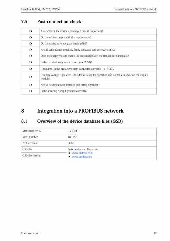
8.1 Overview of the device database files (GSD)
Manufacturer ID 17 (0x11)
Ident number 0x1558
Profile version 3.02
GSD file Information and files under:• www.endress.com• www.profibus.orgGSD file version
Integration into a PROFIBUS network Levelflex FMP51, FMP52, FMP54
38 Endress+Hauser
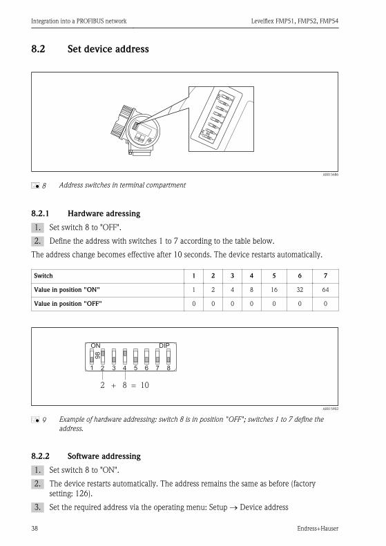
8.2 Set device address
2
98
34
56
78
1
DIP
ON
A0015686
å 8 Address switches in terminal compartment
8.2.1 Hardware adressing
1. Set switch 8 to OFF .
2. Define the address with switches 1 to 7 according to the table below.
The address change becomes effective after 10 seconds. The device restarts automatically.
Switch 1 2 3 4 5 6 7
Value in position ON 1 2 4 8 16 32 64
Value in position OFF 0 0 0 0 0 0 0
2
98
3 4 5 6 7 81
DIPON
2 + 8 = 10
A0015902
å 9 Example of hardware addressing: switch 8 is in position OFF ; switches 1 to 7 define theaddress.
8.2.2 Software addressing
1. Set switch 8 to ON .
2. The device restarts automatically. The address remains the same as before (factorysetting: 126).
3. Set the required address via the operating menu: Setup ® Device address

Levelflex FMP51, FMP52, FMP54 Integration into a PROFIBUS network
Endress+Hauser 39
2
98
3 4 5 6 7 81
DIPON
A0015903
å 10 Example of software addressing; switch 8 is in position ON ; the address is defined in theoperating menu (Setup ® Device address)

Commissioning via operating menu (On-site display, FieldCare) Levelflex FMP51, FMP52, FMP54
40 Endress+Hauser
9 Commissioning via operating menu (On-sitedisplay, FieldCare)
9.1 Display and operating module
9.1.1 Display appearance
3.1
3.2
2.1
2.2
2.4
2.5
1.1
1.2
1.3
1.4
2.3
2.6
1
2
3
45
ESC
OP
EN
OP
EN
E
ABC_ DEFG
UserHIJK
LMNO PQRS TUVW
XYZ Aa1
3 40 1 295 6 87
20
A0012635
å 11 Appearance of the display and operation module for on-site operation
1 Measured value display (1 value max. size)1.1 Header containing tag and error symbol (if an error is active)1.2 Measured value symbols1.3 Measured value1.4 Unit2 Measured value display (2 values)2.1 Bargraph for measured value 12.2 Measured value 1 (including unit)2.3 Measured value symbols for measured value 12.4 Measured value 22.5 Unit for measured value 22.6 Measured value symbols for measured value 23 Representation of a parameter (here: a parameter with selection list)3.1 Header containing parameter name and error symbol (if an error is active)3.2 Selection list; Â marks the current parameter value.4 Input matrix for numbers5 Input matrix for alphanumeric and special characters

Levelflex FMP51, FMP52, FMP54 Commissioning via operating menu (On-site display, FieldCare)
Endress+Hauser 41
9.1.2 Navigation and selection from a listUse the operating keys to navigate within the operating menu and to select options from a list.
Key Meaning
A0011971
Minus keyHenceforth represented by S.• In a selection list: Moves the selection bar upward.• In an input matrix: Moves the selection bar backward.
A0011972
Plus keyHenceforth represented by O.• In a selection list: Moves the selection bar downward.• In an input matrix: Moves the selection bar forward.
E
A0011973
Enter keyHenceforth represented by F.• Opens the marked submenu or parameter.• Confirms a changed parameter value.
+
A0012661
Escape key combination (press keys simultaneously)Henceforth represented by S + O.• Closes a parameter without accepting the changes.• Quits the current menu layer and returns to the next higher layer.

Commissioning via operating menu (On-site display, FieldCare) Levelflex FMP51, FMP52, FMP54
42 Endress+Hauser
9.2 Operating concept
9.2.1 Structure
Language
Display/operation Parameter 1
Parameter 2
Parameter N
Setup Setup parameter 1
Setup parameter 2
Setup parameter N
Advanced setup Enter access code
Parameter 1
Parameter N
Submenu 1
Submenu N
Diagnostics Parameter 1
Parameter N
Submenu 1
Submenu N
Expert Direct access
System
Sensor
Output
Communication
Application
Diagnostics
A0011407-EN
å 12 Basic structure of the operating menu; gray: submenus; white: parameters

Levelflex FMP51, FMP52, FMP54 Commissioning via operating menu (On-site display, FieldCare)
Endress+Hauser 43
9.2.2 Submenus and user rolesThe submenus are designed for different user roles. A user role is defined by typical taskswithin the lifecycle of the device.
User role Typical tasks Submenu
Operator Tasks in the ongoing process:• Configuration of the display.• Reading measuring values.
LanguageDefines the operating language (® ä 46).
Display/OperationContains all parameters which are neededduring the ongoing process: configuration ofthe display (display values, display format,display contrast ...).
Maintenance Commissioning:• Configuration of the measurement.• Configuration of the measured value processing
(scaling, linearization, limit detection etc.).• Configuration of the measured value output
(analog and digital communication interface).
SetupContains all commissioning parameters(® ä 47).
Error handling DiagnosticsContains all parameters needed to detect ananalyze operational errors.
Expert Tasks which require detailed knowledge about theinstrument:• Commissioning of measurements under
demanding conditions.• Optimization of the measurement under
demanding conditions.• Detailed configuration of the communication
interface.• Error diagnosis in diffcult cases.
Expert
Commissioning via operating menu (On-site display, FieldCare) Levelflex FMP51, FMP52, FMP54
44 Endress+Hauser
9.3 Adjust the display contrast• O + F (pressed simultaneously): increases the contrast.• S + F (pressed simultaneously): decreases the contrast.
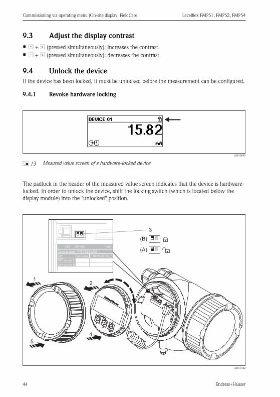
9.4 Unlock the deviceIf the device has been locked, it must be unlocked before the measurement can be configured.
9.4.1 Revoke hardware locking
A0013649
å 13 Mesured value screen of a hardware-locked device
The padlock in the header of the measured value screen indicates that the device is hardware-locked. In order to unlock the device, shift the locking switch (which is located below thedisplay module) into the unlocked position.
12
5
4
3
(B)
(A)CDI
Spare part: FMP52X-AB
WP SIM
SW ex works
SW update #1
SW update #2
02.01.03 Dev_R
DISPL
A0013132

Levelflex FMP51, FMP52, FMP54 Commissioning via operating menu (On-site display, FieldCare)
Endress+Hauser 45
1. Unscrew the lid from the compartment for the display and operating module.
2. Slightly turn the display and operating module to remove it from the compartment.
3. Set the locking switch (WP: Write Protection) into the desired position. (A): unlocked;(B): locked.
4. Attach the display and operating module in the desired orientation until it closes with asnap.
5. Screw the lid onto the compartment.
9.4.2 Revoke software locking
E
A0013651
å 14 Input prompt for the access code to unlock software-locked parameters.
Parameters affected by the software lock are marked by a padlock in front of the parametername. After pressing F an input prompt appears. Enter the user defined locking code tounlock the device.
Step Parameter Action
1 Setup ® Advanced setup ® Define access code To lock the device:Enter a user-defined access code.
2 Setup ® Advanced setup ® Enter access code To unlock the device:Enter the previously defined access code.
3 Setup ® Advanced setup ® Enter access code To lock the device again:Enter a number other than the previously definedaccess code.

Commissioning via operating menu (On-site display, FieldCare) Levelflex FMP51, FMP52, FMP54
46 Endress+Hauser
9.5 Set the operating language
E E
E
+
1. 4.
2. 5.
3.
A0013637

Levelflex FMP51, FMP52, FMP54 Commissioning via operating menu (On-site display, FieldCare)
Endress+Hauser 47
9.6 Configuration of a level measurement
F
L
D
E
20 mA
100%
4 mA
0%
LN
R
A0011360
å 15 Configuration parameters for level measurements in liquids
LN = Length of probe R = Reference point of the measurement
D = Distance E = Empty calibration (= Zero point)
L = Level F = Full calibration (= span)
Step Parameter Action
1 Setup ® Distance unit Select distance unit.
2 Setup ® Operating mode 1) Select Level .
3 Setup ® Tank type Select tank type.
4 Setup ® Tube diameter 2) Enter the diameter of the bypass or stilling well.
5 Setup ® Medium group Select medium group ( water based or other )
6 Setup ® Empty calibration Enter the distance E between the reference point R and theminimum level (0%).
7 Setup ® Full calibration Enter distance F between the minimum (0%) and maximum (100%)level.
8 Setup ® Level Displays the measured level L.
9 Setup ® Distance Displays the distance D between the reference point R and the levelL.

Commissioning via operating menu (On-site display, FieldCare) Levelflex FMP51, FMP52, FMP54
48 Endress+Hauser
Step Parameter Action
10 Setup ® Signal quality Displays the signal quality of the level echo.
11 Setup ® Mapping ® Confirm distance 3) Compare the displayed distance to the real distance in order to startthe recording of the mapping curve.
1) only visible for devices with interface measurement application package2) only visible for coated probes and if Tank type = Bypass/pipe3) For FMP54 with gas phase compensation (product structure: feature 540 Application Package , option EF or
EG) a map must NOT be recorded.
9.7 Configuration of an interface measurementOnly devices with the respective software option can be used for interfacemeasurements. This option is selected in the product structure: Feature 540 Applicationpackage , option EB Interface measurement .
DL
LLF
LI
UP
DI
LNE
R
0%
100%
DK (DC )2 2
DK DC1 1( )
A0011177
å 16 Configuration parameters for interface measurements
R = Reference pioint of the measurement DI = Distance of interface (Distance from reference point to lowermedium)
E = Empty calibration (= zero point) LI = Interface level
F = Full calibration (= span) DL = Distance from reference point R to total level
LN = Length of probe LL = total level
UP = Thickness of upper medium
Levelflex FMP51, FMP52, FMP54 Commissioning via operating menu (On-site display, FieldCare)
Endress+Hauser 49
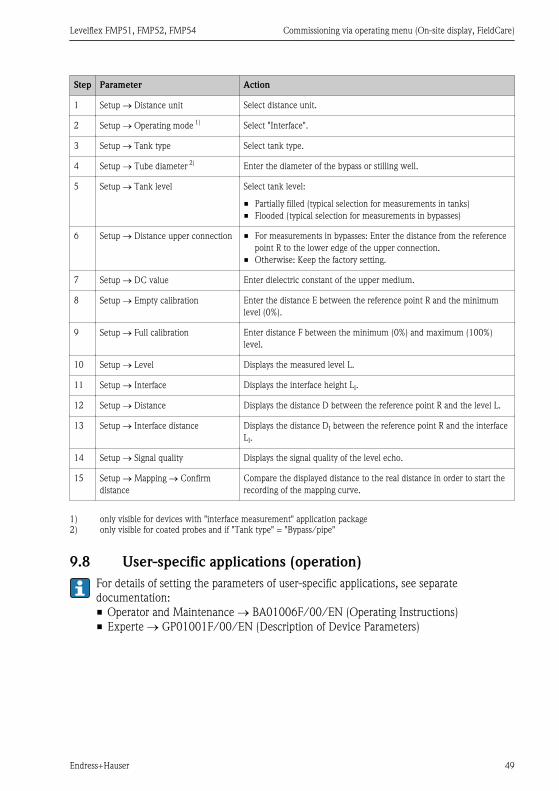
Step Parameter Action
1 Setup ® Distance unit Select distance unit.
2 Setup ® Operating mode 1) Select Interface .
3 Setup ® Tank type Select tank type.
4 Setup ® Tube diameter 2) Enter the diameter of the bypass or stilling well.
5 Setup ® Tank level Select tank level:
• Partially filled (typical selection for measurements in tanks)• Flooded (typical selection for measurements in bypasses)
6 Setup ® Distance upper connection • For measurements in bypasses: Enter the distance from the referencepoint R to the lower edge of the upper connection.
• Otherwise: Keep the factory setting.
7 Setup ® DC value Enter dielectric constant of the upper medium.
8 Setup ® Empty calibration Enter the distance E between the reference point R and the minimumlevel (0%).
9 Setup ® Full calibration Enter distance F between the minimum (0%) and maximum (100%)level.
10 Setup ® Level Displays the measured level L.
11 Setup ® Interface Displays the interface height LI.
12 Setup ® Distance Displays the distance D between the reference point R and the level L.
13 Setup ® Interface distance Displays the distance DI between the reference point R and the interfaceLI.
14 Setup ® Signal quality Displays the signal quality of the level echo.
15 Setup ® Mapping ® Confirmdistance
Compare the displayed distance to the real distance in order to start therecording of the mapping curve.
1) only visible for devices with interface measurement application package2) only visible for coated probes and if Tank type = Bypass/pipe
9.8 User-specific applications (operation)For details of setting the parameters of user-specific applications, see separatedocumentation:• Operator and Maintenance ® BA01006F/00/EN (Operating Instructions)• Experte ® GP01001F/00/EN (Description of Device Parameters)


*71206446*71206446
KA01079F/00/EN/13.1271206446CCS/COSIMA