
Level measurement
25
Principle of operation of the following types of level instrumentation: a. Gauge glass b. Ball float c. Chain float c. Chain float d. Magnetic bond e. Conductivity probe f. Differential pressure (DP)
-
Upload
farrukh-shehzad -
Category
Business
-
view
1.254 -
download
1
Transcript of Level measurement

Principle of operation of the following types of
level instrumentation:
a. Gauge glass
b. Ball float
c. Chain floatc. Chain float
d. Magnetic bond
e. Conductivity probe
f. Differential pressure (DP)

Gauge Glass• A very simple means by which liquid level is
measured in a vessel is by the gauge glass method
• (Figure 1). In the gauge glass method, a transparent tube is attached to the bottom and top (topand top (top
• connection not needed in a tank open to atmosphere) of the tank that is monitored. The height
• of the liquid in the tube will be equal to the height of water in the tank.


Figure 1 (a) shows a gauge glass which is used for vessels where the liquid is at ambient temperature and pressure conditions. Figure 1 (b) shows a gauge glass which is used for vessels
where the liquid is at an elevated pressure or a partial vacuum. Notice that the gauge partial vacuum. Notice that the gauge glasses in
Figure 1 effectively form a "U" tube manometer where the liquid seeks its own level due to the
pressure of the liquid in the vessel.

Gauge glasses made from tubular glass or plastic are
used for service up to 450 psig and 400°F.
If it is desired to measure the level of a vessel at
higher temperatures and pressures, a different
type of gauge glass is used. The type of gauge
glass utilized in this instance has a body made
of metal with a heavy glass or quartz section for of metal with a heavy glass or quartz section for
visual observation of the liquid level. The glass
section is usually flat to provide strength and
safety.

• Another type of gauge glass is the reflex gauge
glass (Figure 3). In this type, one side of the
glass section is prism-shaped. The glass is molded
such that one side has 90-degree angles which
run lengthwise. Light rays strike the outer surface
of the glass at a 90-degree angle. The light
rays travel through the glass striking the inner side rays travel through the glass striking the inner side
of the glass at a 45-degree angle. The
presence or absence of liquid in the chamber
determines if the light rays are refracted into the
chamber or reflected back to the outer surface of
the glass.


• When the liquid is at an intermediate level in the gauge glass, the light rays encounter an
air-glass interface in one portion of the chamber and a water-glass interface in the other portion
of the chamber. Where an air-glass interface exists, the light rays are reflected back to the outer
surface of the glass since the critical angle for light to pass from air to glass is 42 degrees. This
causes the gauge glass to appear silvery-white. In the portion of the chamber with thechamber with the
water-glass interface, the light is refracted into the chamber by the prisms.
Reflection of the light back to the outer surface of the gauge glass does not occur because the critical angle for light to pass from glass to water is 62-degrees. This results in the glass appearing black, since it is possible to see through the water to the walls of the chamber which are painted black. Light is lost from this path in to the liquid according to the depth of the liquid surrounding the prism.

• A third type of gauge glass is the refraction type
(Figure 4). This type is especially useful in
areas of reduced lighting; lights are usually
attached to the gauge glass. Operation is based on
the principle that the bending of light, or
refraction, will be different as light passes through


Ball Float
• The ball float method is a direct reading liquid
level mechanism. The most practical design for
the float is a hollow metal ball or sphere.
However, there are no restrictions to the size,
shape, or material used. The design consists of a
ball float attached to a rod, which in turn is
Kamran Khalid
ball float attached to a rod, which in turn is
connected to a rotating shaft which indicates level
on a calibrated scale (Figure 5). The operation of
the ball float is simple. The ball floats on top of
the liquid in the tank. If the liquid level changes,
the float will follow and change the position of the
pointer attached to the rotating shaft.


The travel of the ball float is limited by its design to
be within ±30 degrees from the horizontal
plane which results in optimum response and
performance. The actual level range is determined
by the length of the connecting arm.
The stuffing box is incorporated to form a water-tight
seal around the shaft to prevent leakageseal around the shaft to prevent leakage
from the vessel.
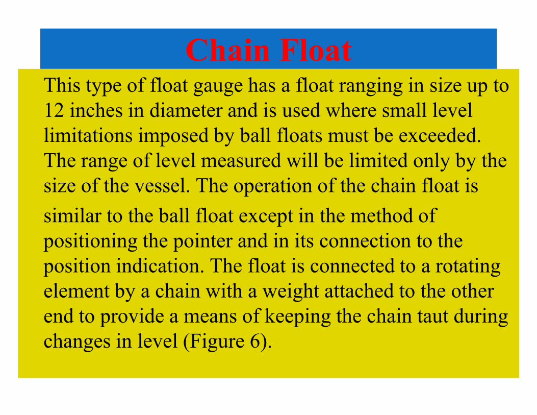
Chain FloatThis type of float gauge has a float ranging in size up to
12 inches in diameter and is used where small level
limitations imposed by ball floats must be exceeded.
The range of level measured will be limited only by the
size of the vessel. The operation of the chain float is
similar to the ball float except in the method of similar to the ball float except in the method of
positioning the pointer and in its connection to the
position indication. The float is connected to a rotating
element by a chain with a weight attached to the other
end to provide a means of keeping the chain taut during
changes in level (Figure 6).
Kamran Khalid

Magnetic Bond Method
The magnetic bond method was developed to
overcome the problems of cages and stuffing
boxes. The magnetic bond mechanism consists of
a magnetic float which rises and falls with
changes in level. The float travels outside of achanges in level. The float travels outside of a
non-magnetic tube which houses an inner magnet
connected to a level indicator. When the float
rises and falls, the outer magnet will attract the
inner magnet, causing the inner magnet to follow
the level within the vessel (Figure 7).

Kamran Khalid

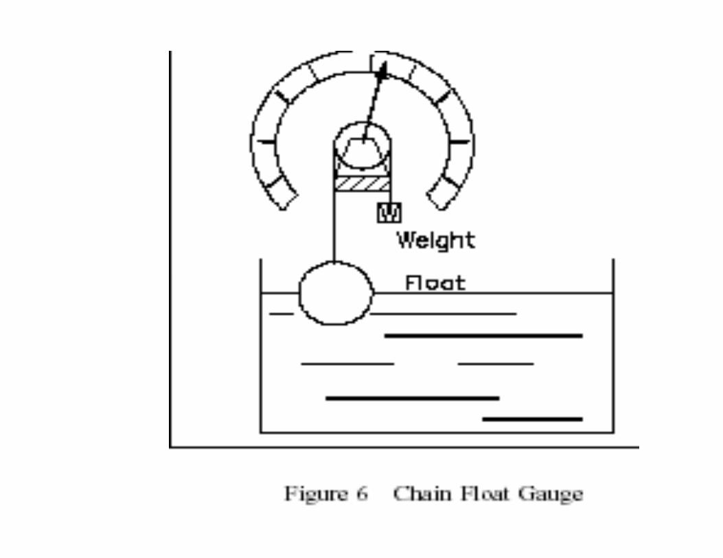
Conductivity Probe Method
Figure 8 illustrates a conductivity probe level
detection system. It consists of one or more level
detectors, an operating relay, and a controller.
When the liquid makes contact with any of the
electrodes, an electric current will flow between the
Kamran Khalid
electrodes, an electric current will flow between the electrode and ground. The current energizes
a relay which causes the relay contacts to open or close depending on the state of the process
involved. The relay in turn will actuate an alarm, a pump, a control valve, or all three. A typical
system has three probes: a low level probe, a high level probe, and a high level alarm probe.
Kamran Khalid
Differential Pressure Level Detectors
The differential pressure (∆P) detector method of liquid level measurement uses a ∆P detector
connected to the bottom of the tank being monitored. The higher pressure, caused by the fluid
in the tank, is compared to a lower reference pressure (usually atmospheric). This comparison
takes place in the ∆P detector. Figure 9 illustrates a typical differential pressure detector attached
to an open tank.

Kamran Khalid

Specific Volume. Specific volume is defined as volume per unit
mass as shown Specific Volume = Volume/Mass
Specific volume is the reciprocal of density as shown in Equation
Specific Volume 1/density
Specific volume is the standard unit used when working with
vapors and steam that have low values of density.
For the applications that involve water and steam, specific volume
can be found using "Saturated Steam Tables," which list the
Kamran Khalid
can be found using "Saturated Steam Tables," which list the
specific volumes for water and saturated steam at different
pressures and temperatures. The density of steam (or vapor)
above the liquid level will have an effect on the weight of the
steam or vapor bubble and the hydrostatic head pressure. As the
density of the steam or vapor increases, the weight increases and
causes an increase in hydrostatic head even though the actual
level of the tank has not changed. The larger the steam bubble,
the greater the change in hydrostatic head pressure.

Pressurizer Level InstrumentsFigure 13 shows a typical pressurizer level system.
Pressurizer temperature is held fairly constant during
normal operation. The ∆P detector for level is calibrated with the pressurizer hot, and the effects of density changes do not occur. The pressurizer will not always be hot. It may be cooled down for will not always be hot. It may be cooled down for non-operating maintenance conditions, in which case a second ∆P detector, calibrated for level measurement at low temperatures, replaces the normal ∆P detector. The density has not really been compensated for; it has actually been aligned out of the instrument by calibration.


For more chemical engineering eBooks and
solution manuals visit here
www.chemicallibrary.blogspot.com